real-time full body motion imitation on the … · 1 real-time full body motion imitation on 2 the...
TRANSCRIPT

REAL-TIME FULL BODY MOTION IMITATION ON1
THE COMAN HUMANOID ROBOT2
Andrej Gams1,2, Jesse van den Kieboom2, Florin Dzeladini2,
Ales Ude1 and Auke Jan Ijspeert2
1Dept. of Automation, Biocybernetics and Robotics
Jozef Stefan Institute
Jamova 39, 1000 Ljubljana, Slovenia
2Biorobotics Laboratory
Ecole Polytechnique Federale de Lausanne
Station 14, CH-1015 Lausanne, Switzerland
andrej.gams, [email protected]
jesse.vandenkieboom, florin.dzeladini, [email protected]
3
ABSTRACT- On-line full body imitation with a humanoid robot standing on4
its own two feet requires simultaneously maintaining the balance and imitating5
the motion of the demonstrator. In this paper we present a method that allows6
real-time motion imitation while maintaining stability, based on prioritized7
task control. We also describe a method of modified prioritized kinematic8
control that constrains the imitated motion to preserve stability only when9
the robot would tip over, but does not alter the motions otherwise. To cope10
with the passive compliance of the robot, we show how to model the estimation11
of the center-of-mass of the robot using support vector machines. In the paper12
we give detailed description of all steps of the algorithm, essentially providing13
a tutorial on the implementation of kinematic stability control. We present the14
results on a child sized humanoid robot called Compliant Humanoid Platform15
or COMAN. Our implementation shows reactive and stable on-line motion16
imitation of the humanoid robot.17

Keywords: kinematics, motion imitation, stability, center-of-mass, SVM18
1 Introduction19
The transfer of human motion to humanoid robots can be accomplished in20
many manners, one of them being motion capture (1,2). Different kinematic21
and dynamic properties of humans and robotic mechanisms do not allow direct22
transfer or mapping of movement from one to the other.3 This becomes even23
more evident when the robot should be, just as the demonstrator, standing on24
its own feet. For example, recorded joint movement of humans when squatting25
will, if directly copied to a humanoid robot, most likely result in the robot26
tipping over.27
Thus the observed human motion needs to be adapted to the properties of the28
humanoid robot, but this requires the availability of models specifying robot29
kinematics and dynamics in order to control the robot’s stability criterion.30
Probably the most commonly used criterion to maintain robotic stability is31
the zero moment point (ZMP) (4,5), defined as the point on the ground where32
the tipping moment acting on the humanoid robot, due to gravity and inertia33
forces, equals zero (6). A biped humanoid robot is dynamically stable at34
any given time if its ZMP lies within the area defined by the convex hull of35
the supporting feet – in the double support phase, or one foot in the single36
support phase. ZMP is commonly used to evaluate the center of mass (CoM)37
acceleration boundaries, i.e. to determine the highest possible accelerations of38
the CoM, which keep the ZMP inside of the support polygon.39
This method was for example used by Harada et al.,7 who developed the ZMP40
dynamic-evaluation criterion, which enables generalized multicontact locomo-41
tion behaviors. Kajita et al.8 designed a control system which minimizes the42
error between the desired ZMP and the output ZMP by applying a preview43
controller. Later Hyon et al.9 proposed the compliant multicontact behavior44

using optimal distribution of contact forces. Even before that Sugihara et al.1045
applied an inverted pendulum control to generate dynamically stable walking46
patterns in real-time. The advantage of inverted pendulum approaches is that47
they require only a rough model of the robot dynamics to be successful.48
One of the above mentioned approaches is commonly used to constrain the49
movement of the robot, so that the ZMP moves along the desired trajectory50
or even remains stationary.1151
Humanoid robots are kinematically redundant.12 The redundant DOFs can52
be used to effectively control the stability while performing some other task.53
The prioritized task control can be used to implement such behaviors. For the54
case of stability control, the motion of ZMP is considered as a primary task55
while other tasks or movements are considered as secondary tasks projected56
onto the null space of the primary task.57
The goal of this paper is to show how to integrate stability control with motion58
capture systems to generate stable reproductions of human movements in real-59
time. We propose to exploit the kinematical redundancy of a humanoid robot60
and apply whole-body prioritized control. In the context of humanoid robots,61
prioritized control was used for example to enable the unified control of center62
of mass, operation-space tasks, and internal forces.13 Prioritized control for63
locomotion and balance control was also addressed by Mistry et al.1464
Since keeping the stability of a robot is normally the most important motor65
task, it thus constrains all other tasks to its null space and effectively alters66
the motions executed on the robot. In this paper we propose and evaluate67
a method which in certain situations allows unconstrained execution of the68
secondary task while the robot is securely stable. The primary task of stability69
control takes over only when approaching a predefined threshold, when the70
robot is in danger of becoming unstable. On top of that, it also allows smooth,71
continuous and reversible transition between the two modes. Such behavior,72

when applied to stability control, allows arbitrary movement of the robot while73
it is in a stable configuration. Furthermore, it does not interfere with the74
desired movement, for example the demonstrated movement the robot should75
track. Once a predefined threshold of a selected criterion, e.g. the location76
of ZMP is reached, the primary task takes over, and constrains the desired,77
demonstrated movement.78
To demonstrate the applicability of the algorithm we show how it can be ap-79
plied to real-time motion imitation of a humanoid robot, which at the same80
time preserves stability by standing on its own two feet. We performed the81
experiments on the Compliant Humanoid Platform or COMAN, which boasts82
14 series-elastic joints, of which 6 in the legs are in the sagittal plane. The83
discrepancies between the CAD data of the robot and the real robot, and the84
passive elements in the kinematic chains lead to an error of the estimation of85
the center-of-mass. We show in the paper how we can model the discrepan-86
cies with the use of support vector machines, a supervised machine learning87
approach.15,16 Other approaches were demonstrated to account for the behav-88
ior of the springs on the same platform. Lee et al.17 have used a time-delay89
estimation in their control scheme, focusing on the behavior when carrying90
load. On the other hand, Mosadeghzad et al.18 have proposed optimal com-91
pliance regulation. The emphasis of the paper was on the control with respect92
to external impacts. A model free approach, completely excluding the kine-93
matics, was used for postural control of the same compliant robotic platform94
by Gay et. al.19 In their approach, the authors used visual flow and gyro-95
scopes as the input into optimized neural networks. In our paper, we show96
how we can perform postural control and motion imitation online, without97
of-line optimization.98
To implement the real-time motion imitation we used a low cost RGB-D sensor,99
namely Kinect for the tracking of a human body. A similar approach applied100

to a dynamic simulation was proposed by.20 Real-time motion transfer using101
precise motion capture on a Nao robot was described by.21 Dynamic motion102
capture and imitation using motion capture was described by Ramos et al.22103
The paper describes of-line optimizations of motion and uses precise motion104
capture, while we describe real-time on-line motion imitation, where the pos-105
sibility of optimizing motions is limited by the time-step of the control loop.106
Even so, we achieve reactive and stable motion imitation, which we demon-107
strated on a real robotic platform. In a recent paper, Zheng and Yamane23 have108
extended motion tracking with strict contact force constraints, implemented109
by solving a nonlinear optimization problem with complex constraints in every110
control-loop step. They demonstrated the results in a dynamics simulator.111
In order to apply the prioritized task control on the robot one needs the com-112
plete kinematic description of the robot and the means to control the CoM or113
ZMP using inverse kinematics. In Section 2 we briefly outline the calculation114
of kinematic descriptions of humanoid robots. In Section 3 we present motion115
imitation based on prioritized task control. The paper continues with the al-116
gorithm to manipulate the ZMP through the COM and the final prioritized117
control. Section 4 explains the modified task control, while Section 5 gives the118
results on the real robot. In Section 6 we describe how we can model the be-119
havior of passive elements of the robot using SVM. Discussion and conclusions120
are given in Section 7.121
2 Kinematics of a Humanoid Robot122
When calculating the kinematics of a humanoid robot, one has to take into123
consideration that the robot is not attached to the ground, as it is the case124
with conventional industrial manipulators. A humanoid robot is bound to125
the ground by a one-way constraint, given by the current support plane, for126
instance with the feet. Defining an inertial frame is necessary in order to127

describe the position and orientation of the multi-legged kinematic chain with128
the use of systematical approaches for serial mechanisms.129
The humanoid robot can be modeled as a combination of four kinematic chains,130
one for each limb, which all originate in the same starting point, called the base131
or root.24 This point is often in the “abdomen” of the robot. The base frame132
attached to the robot is then connected to the inertial frame via 6 unactuated133
DOFs. In a kinematical aspect, using these DOF to calculate the kinematics134
becomes equivalent to imposing a null velocity reference to the feet.24 Since135
these DOFs cannot be directly actuated, the term floating-base systems is136
often used to describe them.137
Systematical approaches for serial mechanisms can be used to describe the138
kinematics of each of the four chains of a humanoid robot. The four chains139
consist of the two legs and the two arms (see Fig.1 showing the robot). Any140
systematical approach, such as the DenavitHartenberg (DH) parameters or the141
vector parameters25 can be used for the description of the kinematic description142
of the chains.143
3 Motion Imitation with Stability Control144
The task of our algorithm is to allow on-line motion imitation on top of stabil-145
ity control. Therefore we have chosen the primary task to be stability control146
and the secondary task to be imitation of a demonstrator’s movements, ex-147
tracted with the Kinect sensor. In order to keep the robot stable, we wish to148
manipulate ZMP through the CoM. The relationship between the velocity of149
the center of mass in base coordinates (denoted by b) bxCoM and joint angle150
velocity q is given by the Jacobian of the center of mass JCoM ∈ R3.151

3.1 Center of Mass Jacobian152
The center-of-mass Jacobian in base coordinates bJCoM is obtained from153
bxCoM =
∑ni=1m
bixi∑n
i=1mi
(1)
from the relation154
bxCoM =
∑ni=1 mi
bJiq∑ni=1 mi
=
∑ni=1 mi
bJi∑ni=1mi
q = bJCoMq. (2)
where bJi is the geometric Jacobian of the center of mass of body part i in155
base coordinates. Algorithm 1 gives a pseudo code on how to calculate the156
CoM Jacobian.157
Algorithm 1 Center of Mass Jacobian
1: function JCoM
2: M =∑n
j=1 mj
3: for all kinematic chains do
4: mλ = 0;
5: for j = n : −1 : 1 do
6: mλ = mλ +mj
7: pCoM,j = mjxCoM,j/mλ −Oj
8: JCoM,j = mλ/M(rj × pCoM,j) . × cross product
Basically, to calculate the center-of-mass Jacobian, one calculates how much a158
differential motion of a separate joint differentially displaces the center of mass.159
The pseudocode provided in algorithm 1 starts at the end of a kinematic chain160
and calculates the effect of moving the last joint, all the way to the first joint161
in the chain, which moves the mass of the complete chain. In this pseudocode,162
the variable pCoMjis an auxiliary variable, Oj refers to the origin of frame j,163
rj is the j−th joint axis direction in the base frame, and mλ is the recursively164
calculated mass from the current frame to the end of the kinematic chain.165
The complete JCoM is calculated by combining the JCoM,j columns of all the166
kinematic chains.167
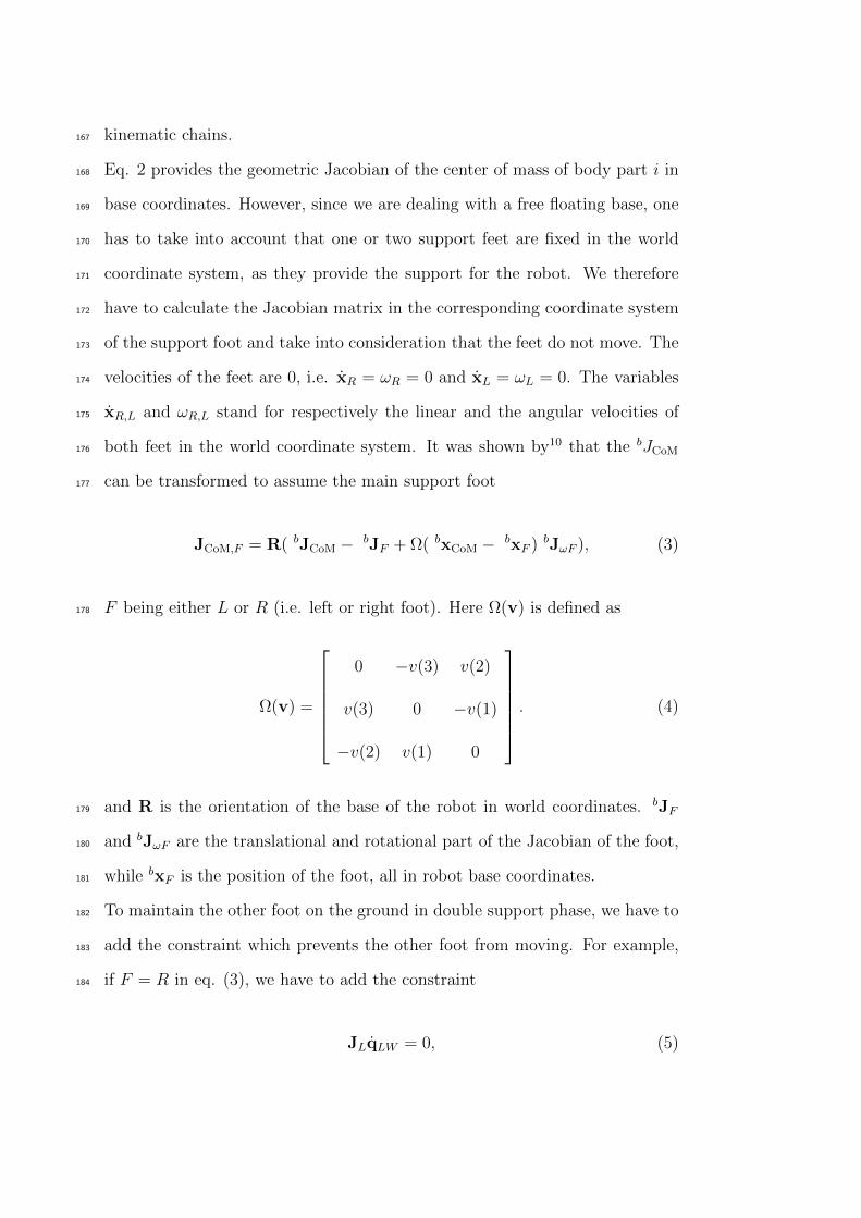
Eq. 2 provides the geometric Jacobian of the center of mass of body part i in168
base coordinates. However, since we are dealing with a free floating base, one169
has to take into account that one or two support feet are fixed in the world170
coordinate system, as they provide the support for the robot. We therefore171
have to calculate the Jacobian matrix in the corresponding coordinate system172
of the support foot and take into consideration that the feet do not move. The173
velocities of the feet are 0, i.e. xR = ωR = 0 and xL = ωL = 0. The variables174
xR,L and ωR,L stand for respectively the linear and the angular velocities of175
both feet in the world coordinate system. It was shown by10 that the bJCoM176
can be transformed to assume the main support foot177
JCoM,F = R( bJCoM − bJF + Ω( bxCoM − bxF ) bJωF ), (3)
F being either L or R (i.e. left or right foot). Here Ω(v) is defined as178
Ω(v) =
0 −v(3) v(2)
v(3) 0 −v(1)
−v(2) v(1) 0
. (4)
and R is the orientation of the base of the robot in world coordinates. bJF179
and bJωF are the translational and rotational part of the Jacobian of the foot,180
while bxF is the position of the foot, all in robot base coordinates.181
To maintain the other foot on the ground in double support phase, we have to182
add the constraint which prevents the other foot from moving. For example,183
if F = R in eq. (3), we have to add the constraint184
JLqLW = 0, (5)

where JL ∈ R6xn is the Jacobian of the left foot in the world coordinates and185
qLW the joints that span the chain from the right to the left foot. Figure 2186
illustrates the situation. Since we have all the Jacobian matrices calculated187
in the base coordinate systems, i.e. the kinematic chains originating in the188
abdomen of the robot, we have to generate the Jacobian (in our case when F189
= R) matrix that defines the relation between the joints of both legs and the190
tip of the left foot with respect to the tip of the right foot. The transformation191
can be derived from192
TRL = JL =
RTRRL RT
L(xR − xL)
0 1
, (6)
and deriving separately for the position and the orientation parts. By replacing193
x with Jq and expressing separately for the joints of the left and right foot,194
we get195
JL =
−RRΩ(xL − xR)TJωR −RTRJpR RT
RJpL
−RTRJωR RT
RJωR
, (7)
196
qLW =
qR
qL
. (8)
Considering the constraints of the support feet, the velocity of the center of197
mass and the kinematic constraints with respect to the joint motion, can now198
be expressed as199
xe = Jeq, (9)
where index e stands for augmented. The augmented Jacobian accounts for200
both the stability task and the kinematic constraint with201
xe =
xCoM
0
, (10)

Je =
JCoM
JF
, (11)
for the double support phase. For the single support phase eqs. (10,11) simplify202
into xe = xCoM and Je = JCoM.203
An alternative approach to constraining the motion of the non-leading foot204
would be to simply set the primary task of the robot to maintain the position205
of the other foot and then map the stability control to the null space of the206
task. The drawback is mainly in not having the stability as the primary task207
and therefore the velocities for maintaining the stability are always projected208
through the null space of the task of keeping the feet stationary.209
3.2 ZMP Manipulation Through CoM Jacobian210
Controlling the center-of-mass allows for the control of static stability. In211
order to control the dynamic stability of a humanoid robot we need to control212
its motion so that ZMP stays within the support polygon. It was shown by213
Sugihara et al.10 that, neglecting the inertia matrices, the relationship between214
the CoM, defined in eq. (1) and given by xCoM = [xCoM, yCoM, zCoM], and the215
ZMP can be expressed by216
xCoM = ω2(xCoM − xZMP), (12)
yCoM = ω2(yCoM − yZMP ), (13)
ω =
√zCoM + g
zCoM − zZMP
(14)
Here g is the gravitation constant. Eq. (14) requires desired ZMP planning to217
calculate the desired zCoM, which can be obtained from an inverted pendulum218
control. For details on inverted pendulum control see Kajita et al.26219
Figure 3 shows real robot results of manipulating the measured center of pres-220
sure (CoP), which can be assumed to represent the ZMP when within the221

support polygon,27 with the use of the CoM Jacobian. The main advantage is222
that the robot can react to external forces. In the results of Fig. 3 we can see223
the measured forces, the desired ZMP location, the actual CoP location and224
the actual (estimated) CoM location if both forward-backward (x) and left-225
right (y) directions of the robot. We can see that if an external force appears,226
the CoM is shifted. Due to the passive elements of the robot, the location227
of the CoP overshoots when external forces disappear and the robot wobbles228
slightly. The offset of the forces in the y direction show a discrepancy between229
the model and the real robot.230
3.3 Prioritized task control231
Stable reproduction of human movements can be formulated using prioritized232
control. Classically, one defines the stability as the primary task and movement233
imitation as the secondary task. This leads to the control policy234
q = J+e xe + NqKIN (15)
where N = (I − J+e Je) defines the null space of Je and qKIN are the desired235
joint angles velocities to account for the Kinect tracking of the human motion,236
with qKIN = kp(qactual − qKIN) and kp a positive gain.237
When controlling the non-supporting leg of the robot in the single stance phase,238
one should exclude some of the degrees of freedom from the above matrices.239
The other degrees of freedom should preserve the stability.240
4 Modified Prioritized Task Control241
In the double support phase the robot allows considerable motion of the upper242
part of the body that does not move the ZMP out of the support polygon. The243
lower part, namely the feet, are completely constrained and remain motionless244
on the ground.245
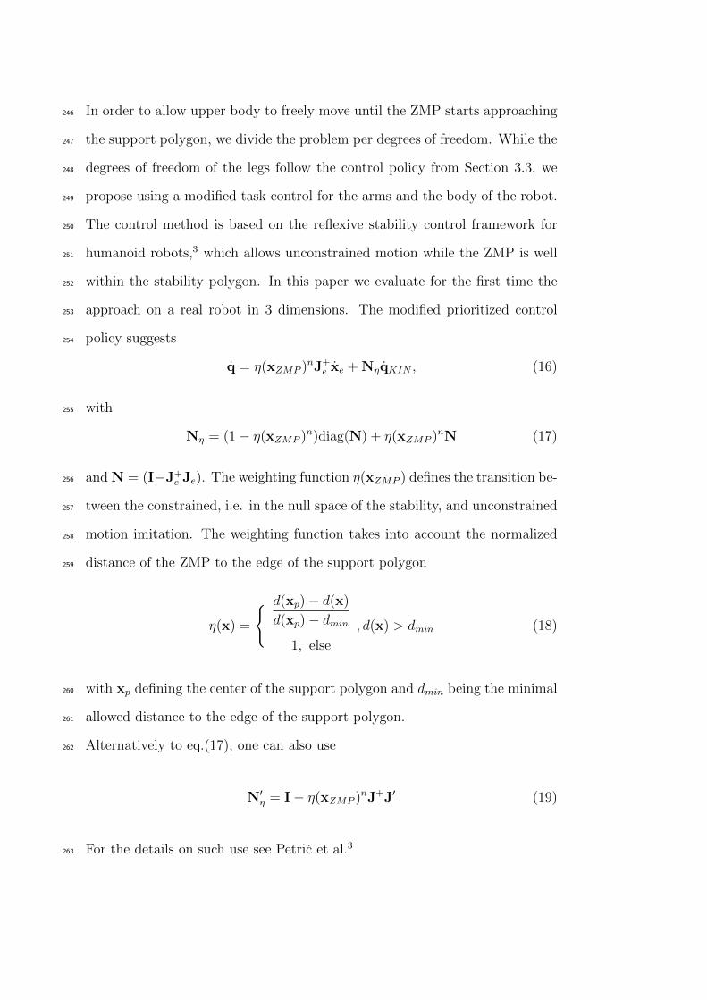
In order to allow upper body to freely move until the ZMP starts approaching246
the support polygon, we divide the problem per degrees of freedom. While the247
degrees of freedom of the legs follow the control policy from Section 3.3, we248
propose using a modified task control for the arms and the body of the robot.249
The control method is based on the reflexive stability control framework for250
humanoid robots,3 which allows unconstrained motion while the ZMP is well251
within the stability polygon. In this paper we evaluate for the first time the252
approach on a real robot in 3 dimensions. The modified prioritized control253
policy suggests254
q = η(xZMP )nJ+e xe + NηqKIN , (16)
with255
Nη = (1− η(xZMP )n)diag(N) + η(xZMP )nN (17)
and N = (I−J+e Je). The weighting function η(xZMP ) defines the transition be-256
tween the constrained, i.e. in the null space of the stability, and unconstrained257
motion imitation. The weighting function takes into account the normalized258
distance of the ZMP to the edge of the support polygon259
η(x) =
d(xp)− d(x)
d(xp)− dmin1, else
, d(x) > dmin (18)
with xp defining the center of the support polygon and dmin being the minimal260
allowed distance to the edge of the support polygon.261
Alternatively to eq.(17), one can also use262
N′η = I− η(xZMP )nJ+J′ (19)
For the details on such use see Petric et al.3263
5 Experimental Evaluation264
In this section we present both simulation and real-world application of the265
proposed modified task priority algorithm for stability control.266
5.1 Compliant Humanoid Platform COMAN267
The Compliant Humanoid Platform COMAN28,29 approximates the dimen-268
sions of a 4 year old child, with the height from the foot to the center of the269
neck 945mm. The distance between the centers of the shoulders is 312mm.270
The total weight of the robot is 31.2kg, out of which the legs and the waist271
module weigh 18.5kg. The complete robot has 25 DOF, but the 2 neck de-272
grees of freedom are not being used at the time. Each leg has 6 DOF: 3 at273
the hip, 1 at the knee level and 2 at the ankle. For the trunk there is a 3274
DOF waist while each arm has currently 4 DOF, i.e. 3 in the shoulder and275
1 in the elbow. Passive compliance based on series elastic actuation (SEA)276
was added to the 14 of the 25 DOF including all flexion/extension DOF of277
the legs, the flexion/extension of the shoulders and elbows and the shoulder278
abduction/adduction. The robot is presented in Fig. 1.279
In the motion imitation algorithm we used the Kinect sensor to track and280
imitate the motion of the complete arms (4 DOF) and of the hips and knees281
of the legs. Additionally, we implemented the rotation of the torso around the282
vertical axis. This was calculated from the positions of the shoulder joints of283
the demonstrator.284
5.2 Experimental results285
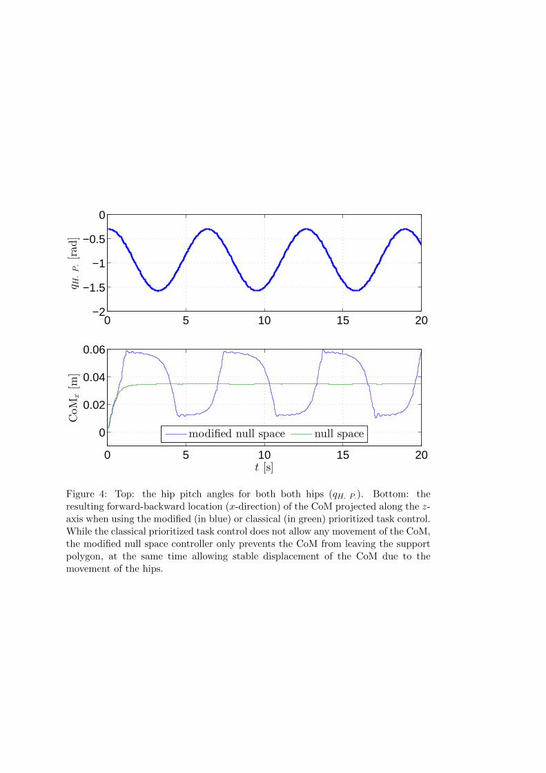
The difference when using modified prioritized task control compared to using286
standard prioritized task space control is that the task with the higher priority287
is only observed when necessary, so stability is only controlled when neces-288
sary. This can be clearly seen in the results of an experiment, where we set289
the desired hip angles of the robot to sinusoidally oscillate from the original290

configuration at -0.3 rad to −π/2 rad, resulting in the robot bending forward291
and backward periodically. The motion of the hips is presented in the top292
plot of Fig. 4. In the bottom plot we can see the location of the CoM. It293
remains stationary when using the classical approach, as reflected in eq. (15),294
which through the primary task reduces the error of the CoM. On the other295
hand, when using the modified task space approach, the CoM moves because,296
as defined in (16), the primary task is pre-multiplied with η(xZMP )n, which is297
virtually zero when close to the center of the support polygon.298
The stability control was set to fully take over 6 cm from the edge of the299
stability polygon. Fig. 5 shows in the top plot how this affects the behavior300
of other joints, in the given case the ankles. We can see that when using301
the modified approach, the joint values remain constant (one instance marked302
with dashed lines) when the distance from the edge of the support polygon is303
sufficient, given by η(xZMP )5 as defined in eq. (18). The value of η(xZMP )5 is304
shown in the bottom plot. In other words, the stability control is not active305
and does not change the (desired) joint positions when η(xZMP )5 ∼= 0.306
Figure 6 shows a sequence of photos showing a simulated robot in a dynamic307
simulator Webots30 imitating the motion of a human in real time. The sequence308
shows the robot lifting one foot. When using the modified task priority control,309
the demonstrator can move the CoM within the support polygon, but has to310
observe the current location of CoM to perform the required motion. In our311
case we defined the desired CoM to move under one foot when the tracking312
detected that the other foot was considerably higher.313
Figure 7 shows the real-time motion imitation of COMAN robot. The demon-314
strator was tracked with the Kinect sensor. We can see imitation with the315
arms, the body and with the legs when performing a squat and bending over.316
The robot safely and reliably maintained the stability with very little delay,317
which can only be observed in very fast demonstrator motions. The algorithm318

has proven very robust and would only fail in the case of tracking errors. A319
video showing the real-time motion imitation on the real robot is available at320
http://biorob.epfl.ch/files/content/sites/biorob/files/public/Coman/KinectDemoVideo.mov.321
6 Estimating Robot-Model Discrepancies Using Sup-322
port Vector Machines323
Since we used only the CAD data to describe the mass properties of the robot324
and since we do not account for the passive elements, there is a discrepancy325
between the position of the center of mass xmodelCoM as calculated from the avail-326
able model data and the actual CoM xCoM. While the discrepancy between the327
model and the real CoM is present in both forward-backward (anteroposterior)328
and left-right (mediolateral) direction of the robot, all of the springs act in the329
sagittal plane and therefore the discrepancy is larger in the anteroposterior330
direction. In this section we show how we can account for the discrepancy331
in the forward-backward direction using support vector machines (SVM).15 A332
similar approach using Gausian Process Regression (GPR) was used to correct333
the estimation of kinematics of a mechanism for manipulation.31334
In our approach we first record a very slow and stable motion of the robot,335
which covers the expected human demonstrated motion and maintains postural336
stability. Due to very slow motion we can assume that the measured center337
of pressure xCoP obtained from pressure sensors on the feet is approximately338
the same as the center of mass xCoM. They both move within the support339
polygon. We can model the error between xmodelCoM and the measured xCoP ≈340
xCoM using SVM regression. We perform the estimation and correction only in341
the anteroposterior (x) direction of the robot. SVM training was implemented342
using the LIBSVM15 library in Matlab. After training we can estimate the343
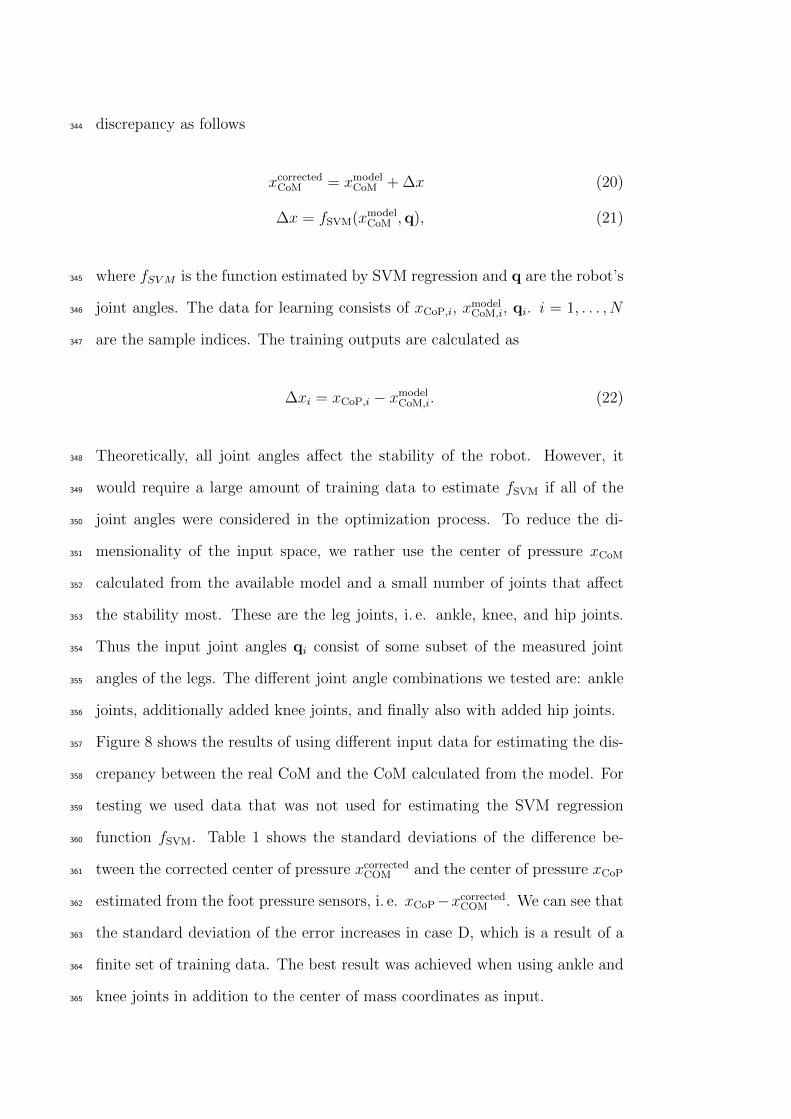
discrepancy as follows344
xcorrectedCoM = xmodel
CoM + ∆x (20)
∆x = fSVM(xmodelCoM ,q), (21)
where fSVM is the function estimated by SVM regression and q are the robot’s345
joint angles. The data for learning consists of xCoP,i, xmodelCoM,i, qi. i = 1, . . . , N346
are the sample indices. The training outputs are calculated as347
∆xi = xCoP,i − xmodelCoM,i. (22)
Theoretically, all joint angles affect the stability of the robot. However, it348
would require a large amount of training data to estimate fSVM if all of the349
joint angles were considered in the optimization process. To reduce the di-350
mensionality of the input space, we rather use the center of pressure xCoM351
calculated from the available model and a small number of joints that affect352
the stability most. These are the leg joints, i. e. ankle, knee, and hip joints.353
Thus the input joint angles qi consist of some subset of the measured joint354
angles of the legs. The different joint angle combinations we tested are: ankle355
joints, additionally added knee joints, and finally also with added hip joints.356
Figure 8 shows the results of using different input data for estimating the dis-357
crepancy between the real CoM and the CoM calculated from the model. For358
testing we used data that was not used for estimating the SVM regression359
function fSVM. Table 1 shows the standard deviations of the difference be-360
tween the corrected center of pressure xcorrectedCOM and the center of pressure xCoP361
estimated from the foot pressure sensors, i. e. xCoP−xcorrectedCOM . We can see that362
the standard deviation of the error increases in case D, which is a result of a363
finite set of training data. The best result was achieved when using ankle and364
knee joints in addition to the center of mass coordinates as input.365

7 Discussion and Conclusion366
We have shown that we can effectively apply the modified prioritized task367
control for simultaneous stability control and motion imitation in real-time.368
In this aspect, we have shown how to apply the described algorithm for both369
center-of-mass and center-of-pressure control approach. While the former is370
somewhat easier to implement, the latter takes into consideration the external371
forces and can adapt the posture of the robot accordingly.372
If ZMP of the robot moves away from the center of the support polygon and373
approaches the edge of the support polygon, our stability control takes over,374
if necessary completely overriding the imitation. The primary task at that375
point only allows motion that would move the ZMP towards the center of the376
support polygon. The prioritized task control, through the Jacobian and if377
enough degrees of freedom are available, may also move the other joints so378
that the secondary task the imitation is observed.379
The presented approaches are effective in controlling the stability, yet several380
issues remain with the applicability to the passively compliant platform used381
in the experiments. As COMAN boasts series elastic elements, i. e. springs382
after the motors, the behavior of the springs cannot be directly influenced and383
specialized controllers need to be developed to account for the spring behav-384
ior. While the springs come in handy for interaction with the environment385
and walking, i. e. to reduce the impact forces, for the task of stability they386
simply introduce an error in the posture. Nevertheless, we successfully demon-387
strated that our method can be applied, despite the inaccuracies brought by388
the springs. They can be partially accounted for by the proposed SVM re-389
gression method. For this method, we first acquire a data set of CoM values390
obtained from the available kinematic model, the center of pressure values391
estimated from the foot pressure sensors, and the associated joint angles of392
the robot. In the future we would like to improve these results with a more393

in-depth analysis of this approach.394
The modified stability approach has allowed us to transfer the motion of the395
demonstrator to the robot in real time, including the lifting of separate legs.396
This proves that the proposed method enables the transfer of human motion397
to the robot without the explicit need for the demonstrator to take into con-398
sideration the behavior of the robot. Since we do not explicitly control the399
stability all the time, but only when necessary, and by keeping a well defined400
prioritized control policy with smooth transitions between the tasks, we can401
perform a variety of tasks, which are not feasible with the strictly prioritized402
approach.403
8 Acknowledgments404
The work presented in this paper was supported by Sciex-NMSCH project 406405
12.018, FP7 project WALK-MAN (FP7-ICT 611832), FP7 project Symbitron406
(FP7-ICT 661626) and FP7 project Xperience (FP7-ICT 270273).407
REFERENCES408
[1] Ales Ude, Christopher G. Atkeson, and Marcia Riley. Planning of joint409
trajectories for humanoid robots using b-spline wavelets. In IEEE Interna-410
tional Conference on Robotics and Automation (ICRA), pages 2223–2228,411
2000.412
[2] A. Gams, A.J. Ijspeert, S. Schaal, and J. Lenarcic. On-line learning and413
modulation of periodic movements with nonlinear dynamical systems. Au-414
tonomous Robots, 27(1):3–23, 2009.415
[3] Tadej Petric, Andrej Gams, Jan Babic, and Leon Zlajpah. Reflexive416
stability control framework for humanoid robots. Autonomous Robots,417
34(4):347–361, 2013.418

[4] Miomir Vukobratovic and Davor Juricic. Contribution to the synthesis of419
biped gait. IEEE Transactions on Biomedical Engineering, BME-16(1):1420
–6, jan. 1969.421
[5] Miomir Vukobratovic and Branislav Borovac. Zero-moment point -422
thirty five years of its life. International Journal of Humanoid Robotics,423
1(1):157–173, 2004.424
[6] P. Sardain and G. Bessonnet. Forces acting on a biped robot. center of425
pressure-zero moment point. IEEE Transactions on Systems, Man and426
Cybernetics, Part A: Systems and Humans, 34(5):630–637, 2004.427
[7] K. Harada, S. Kajita, K. Kaneko, and H. Hirukawa. ZMP analysis for428
arm/leg coordination. In IEEE/RSJ International Conference on Intel-429
ligent Robots and Systems (IROS), volume 1, pages 75 – 81 vol.1, oct.430
2003.431
[8] S. Kajita, F. Kanehiro, K. Kaneko, K. Fujiwara, K. Harada, K. Yokoi, and432
H. Hirukawa. Biped walking pattern generation by using preview control433
of zero-moment point. In IEEE International Conference on Robotics and434
Automation (ICRA), volume 2, pages 1620–1626 vol.2, 2003.435
[9] Sang-Ho Hyon, J.G. Hale, and G. Cheng. Full-body compliant human-436
humanoid interaction: Balancing in the presence of unknown external437
forces. IEEE Transactions on Robotics, 23(5):884 –898, oct. 2007.438
[10] T. Sugihara, Y. Nakamura, and H. Inoue. Real-time humanoid motion439
generation through ZMP manipulation based on inverted pendulum con-440
trol. In IEEE International Conference on Robotics and Automation441
(ICRA), volume 2, pages 1404–1409 vol.2, 2002.442
[11] W. Suleiman, F. Kanehiro, K. Miura, and E. Yoshida. Improving ZMP-443
based control model using system identification techniques. In 9th IEEE-444

RAS International Conference on Humanoid Robots (Humanoids), pages445
74 –80, dec. 2009.446
[12] N. Mansard and F. Chaumette. Task sequencing for high-level sensor-447
based control. Robotics, IEEE Transactions on, 23(1):60 –72, feb. 2007.448
[13] L. Sentis, Jaeheung Park, and O. Khatib. Compliant control of multicon-449
tact and center-of-mass behaviors in humanoid robots. IEEE Transactions450
on Robotics, 26(3):483–501, 2010.451
[14] M. Mistry, J. Nakanishi, and S. Schaal. Task space control with prioritiza-452
tion for balance and locomotion. In IEEE/RSJ International Conference453
on Intelligent Robots and Systems (IROS 2007), pages 331–338, 2007.454
[15] Chih-Chung Chang and Chih-Jen Lin. LIBSVM: A library for support455
vector machines. ACM Transactions on Intelligent Systems and Technol-456
ogy, 2:27:1–27:27, 2011.457
[16] Corinna Cortes and Vladimir Vapnik. Support-vector networks. Machine458
Learning, 20(3):273–297, 1995.459
[17] Jinoh Lee, Houman Dallali, Nikolaos Tsagarakis, and Darwin Caldwell.460
Robust and Model-Free Link Position Tracking Control for Humanoid461
COMAN with Multiple Compliant Joints. In 2013 13th IEEE-RAS In-462
ternational Conference on Humanoid Robots (Humanoids), pages 56 – 61,463
2013.464
[18] Mohamad Mosadeghzad, Zhibin Li, Nikos Tsagarakis, Gustavo A.465
Medrano-Cerda, Houman Dallali, and Darwin G. Caldwell. Optimal An-466
kle Compliance Regulation for Humanoid Balancing Control. In 2013467
IEEE/RSJ International Conference on Intelligent Robots and Systems468
(IROS), pages 4118 – 4123, 2013.469

[19] Sebastian Gay, Jesse van den Kieboom, Jose Santor-Victor, and Auke Jan470
Ijspeert. Model-Based and Model-Free Approaches for Postural Control471
of a Compliant Humanoid Robot using Optical Flow. In 2013 13th IEEE-472
RAS International Conference on Humanoid Robots (Humanoids), pages473
1 – 7, 2013.474
[20] Van Vuong Nguyen and Joo-Ho Lee. Full-body imitation of human mo-475
tions with kinect and heterogeneous kinematic structure of humanoid476
robot. In 2012 IEEE/SICE International Symposium on System Inte-477
gration (SII), pages 93–98, 2012.478
[21] J. Koenemann and M. Bennewitz. Whole-body imitation of human mo-479
tions with a nao humanoid. In 2012 7th ACM/IEEE International Con-480
ference on Human-Robot Interaction (HRI), pages 425–425, 2012.481
[22] O.E. Ramos, L. Saab, S. Hak, and N. Mansard. Dynamic motion capture482
and edition using a stack of tasks. In 2011 11th IEEE-RAS International483
Conference on Humanoid Robots (Humanoids), pages 224–230, 2011.484
[23] Yu Zheng and Katsu Yamane. Human Motion Tracking Control with485
Strict Contact Force Constraints for Floating-Base Humanoid Robots.486
In 2013 13th IEEE-RAS International Conference on Humanoid Robots487
(Humanoids), pages 1 – 7, 2013.488
[24] Agostino Santis, Giuseppe Gironimo, Luigi Pelliccia, Bruno Siciliano, and489
Andrea Tarallo. Multiple-point kinematic control of a humanoid robot.490
In Advances in Robot Kinematics: Motion in Man and Machine, pages491
157–168. Springer Netherlands, 2010.492
[25] T. Bajd, M. Mihelj, J. Lenarcic, A. Stanovnik, and M. Munih. Robotics,493
volume 43 of Intelligent Systems, Control and Automation: Science and494
Engineering. Springer Science+Business Media B.V., 2010.495

[26] S. Kajita, F. Kanehiro, K. Kaneko, K. Yokoi, and H. Hirukawa. The496
3d linear inverted pendulum mode: a simple modeling for a biped walk-497
ing pattern generation. In 2001 IEEE/RSJ International Conference on498
Intelligent Robots and Systems., volume 1, pages 239–246 vol.1, 2001.499
[27] Ambarish Goswami. Postural stability of biped robots and the foot-500
rotation indicator (FRI) point. The International Journal of Robotics501
Research, 18(6):523 – 533, 1999.502
[28] F.L. Moro, N.G. Tsagarakis, and D.G. Caldwell. A human-like walking for503
the compliant humanoid coman based on com trajectory reconstruction504
from kinematic motion primitives. In 2011 11th IEEE-RAS International505
Conference on Humanoid Robots (Humanoids), pages 364–370, 2011.506
[29] L. Colasanto, N.G. Tsagarakis, and D.G. Caldwell. A compact model for507
the compliant humanoid robot coman. In 2012 4th IEEE RAS EMBS508
International Conference on Biomedical Robotics and Biomechatronics509
(BioRob), pages 688–694, 2012.510
[30] O. Michel. Webots: Professional mobile robot simulation. Journal of511
Advanced Robotics Systems, 1(1):39–42, 2004.512
[31] Peter Pastor, Mrinal Kalakrishnan, Jonathan Binney, Jonathan Kelly,513
Ludovic Righetti, Gaurav Sukhatme, and Stefan Schaal. Learning task514
error models for manipulation. In 2013 IEEE International Conference515
on Robotics and Automation (ICRA), pages 2612–2618, 2013.516

List of Figures517
1 COmpliant HuMANoid Platform – COMAN, developed by IIT,518
and used in the experiments to demonstrate the possibility of519
using modified task space control for motion imitation. . . . . . 24520
2 Based on the assumption that the feet do not move when the521
robot is standing, one foot F is considered as the new, fictional522
base of the robot. The Jacobian of the CoM has to be trans-523
formed so that it assumes the new base. The same goes for the524
other foot. When maintaining the other, non-leading foot sta-525
tionary, one can consider the chain from one foot to the other526
as a serial mechanism, given by the red arrow. . . . . . . . . . . 25527
3 The locations of the CoM (red), CoP (green), desired CoP (dot-528
ted) and the measured forces (blue) in the x direction of the529
robot (forward-backward) in the top plot. The same for the530
y direction in the bottom plot. The forces are in N while the531
locations are in cm (for scale) relative to the most stable point532
of the support polygon. . . . . . . . . . . . . . . . . . . . . . . . 26533
4 Top: the hip pitch angles for both both hips (qH. P.). Bot-534
tom: the resulting forward-backward location (x-direction) of535
the CoM projected along the z-axis when using the modified (in536
blue) or classical (in green) prioritized task control. While the537
classical prioritized task control does not allow any movement538
of the CoM, the modified null space controller only prevents the539
CoM from leaving the support polygon, at the same time allow-540
ing stable displacement of the CoM due to the movement of the541
hips. . . . . . . . . . . . . . . . . . . . . . . . . . . . . . . . . . 27542
5 The motion of the ankles (qA. P.) when maintaining the stability543
during the experiment presented also in Fig. 4 in the top plot.544
The value of η5 is shown in the bottom plot. Vertical dashed545
lines mark a time span when the primary task, i.e. stability, is546
not controlled. . . . . . . . . . . . . . . . . . . . . . . . . . . . . 28547
6 Images showing a simulated COMAN robot while imitating hu-548
man behavior in real time. The sequence shows the example549
where the demonstrator performs a side-step. . . . . . . . . . . 29550
7 Sequence of images showing real-time motion imitation with the551
robot while maintaining stability. The demonstrator performed552
random waving, squatting and bending motions, but maintained553
the double feet support at all times. . . . . . . . . . . . . . . . . 30554
8 The results of modeling the robot–model discrepancy using dif-555
ferent input data, presented on the test data. In all four plots,556
the trajectories are green for the xCoM, red for the xCoP and blue557
for the xCoMcorrected . In case A we use only the estimated CoM558
as the input. In case B, we add the ankle joint values, in C we559
add also the knee joint values and in D also the hip joint values. 31560
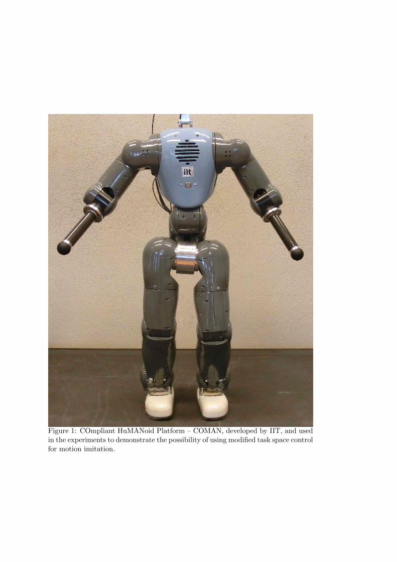
Figure 1: COmpliant HuMANoid Platform – COMAN, developed by IIT, and usedin the experiments to demonstrate the possibility of using modified task space controlfor motion imitation.

x
yz
Support plane
oBase
F
end effector
Figure 2: Based on the assumption that the feet do not move when the robot isstanding, one foot F is considered as the new, fictional base of the robot. The Jaco-bian of the CoM has to be transformed so that it assumes the new base. The samegoes for the other foot. When maintaining the other, non-leading foot stationary,one can consider the chain from one foot to the other as a serial mechanism, givenby the red arrow.

0 10 20 30 40 50 60
−20
−10
0
10
Fx [N] CoMx [cm] CoPx [cm] CoPdes,x [cm]
0 10 20 30 40 50 60−10
01020
t [s]
Fy [N] CoMy [cm] CoPy [cm] CoPdes,y [cm]
Figure 3: The locations of the CoM (red), CoP (green), desired CoP (dotted) andthe measured forces (blue) in the x direction of the robot (forward-backward) in thetop plot. The same for the y direction in the bottom plot. The forces are in N whilethe locations are in cm (for scale) relative to the most stable point of the supportpolygon.
0 5 10 15 20−2
−1.5
−1
−0.5
0
q H.P.[rad]
0 5 10 15 20
0
0.02
0.04
0.06
CoM
x[m
]
t [s]
modified null space null space
Figure 4: Top: the hip pitch angles for both both hips (qH. P.). Bottom: theresulting forward-backward location (x-direction) of the CoM projected along the z-axis when using the modified (in blue) or classical (in green) prioritized task control.While the classical prioritized task control does not allow any movement of the CoM,the modified null space controller only prevents the CoM from leaving the supportpolygon, at the same time allowing stable displacement of the CoM due to themovement of the hips.

0 5 10 15 20
−0.5
−0.4
−0.3
−0.2
q A.P.[rad]
modified null space null space
0 5 10 15 200
0.5
1
η5[rad]
t [s]
Figure 5: The motion of the ankles (qA. P.) when maintaining the stability duringthe experiment presented also in Fig. 4 in the top plot. The value of η5 is shownin the bottom plot. Vertical dashed lines mark a time span when the primary task,i.e. stability, is not controlled.

Figure 6: Images showing a simulated COMAN robot while imitating human behav-ior in real time. The sequence shows the example where the demonstrator performsa side-step.

Figure 7: Sequence of images showing real-time motion imitation with the robotwhile maintaining stability. The demonstrator performed random waving, squattingand bending motions, but maintained the double feet support at all times.

0 20 40
0.02
0.04
0.06A
x[cm]
0 20 40
0.02
0.04
0.06B
0 20 40
0.02
0.04
0.06C
t [s]
x[cm]
0 20 40
0.02
0.04
0.06D
t [s]
Figure 8: The results of modeling the robot–model discrepancy using different inputdata, presented on the test data. In all four plots, the trajectories are green for thexCoM, red for the xCoP and blue for the xCoMcorrected . In case A we use only theestimated CoM as the input. In case B, we add the ankle joint values, in C we addalso the knee joint values and in D also the hip joint values.

List of Tables561
1 Standard deviation of the error (in meters) of xCOM estimation562
using different input and training data . . . . . . . . . . . . . . 33563

Table 1: Standard deviation of the error (in meters) of xCOM estimation usingdifferent input and training data
StandardInput data Deviation
A 0.0102B 0.0067C 0.0062D 0.0065