real-time holographic reconstruction of nmr images using a liquid crystal–spatial light modulator
TRANSCRIPT

Real-Time Holographic Reconstruction of NMR Images Using a
Liquid Crystal�Spatial Light Modulator
Satoshi Ito, Yoshitsugu Kamimura, and Yoshifumi Yamada
Faculty of Engineering, Utsunomiya University, Utsunomiya, Japan 321
SUMMARY
This paper notes that the description of the NMRsignal obtained by NMR imaging is of the same form as thediffraction of the light or sound wave, and discusses thereal-time holographic reconstruction method that recon-structs the NMR image at high speed, using the opticaloperation. With our holographic reconstruction method, notonly can two-dimensional images can be reconstructed in avery short time, but also there is a possibility that three-di-mensional images can be reconstructed in real time. In thisstudy, the phase-scrambling Fourier transform method isused, which requires less dynamic range for the NMRsignal acquisition system. The obtained NMR signal isdirectly transmitted to the electronically directly writableliquid crystal�spatial light modulator and displayed. Then,the NMR image is reconstructed by the coherent opticalsystem. An experiment of imaging and image reconstruc-tion by low-magnetic-field MRI and an experiment usingthe NMR signal derived from the human image obtainedfrom the general-purpose MRI are performed and it isverified that a satisfactory image can be reconstructed fromthe liquid crystal�spatial light modulator with a small num-ber of pixels. A simulation experiment for the real-timereconstruction is also performed in order to examine theusefulness of the proposed method, where NMR signal fora cross section is transmitted and displayed at a 100-msinterval, which is almost the same imaging intervals inultrahigh-speed imaging. It is then verified that the NMRimage can be reconstructed as the dynamic image. © 1999Scripta Technica, Syst Comp Jpn, 31(1): 70�80, 2000
Key words: NMR imaging; real-time reconstruc-tion; holography; liquid crystal�spatial light modulator.
1. Introduction
MRI, which is a tomographic biological imagingsystem based on nuclear magnetic resonance, is widelyused as a clinical device that can display the soft tissues ofthe body. In the past, the time required for measurement andthat required for image reconstruction were both muchlonger than the circulatory and other movements of thebody, and its use has been limited mostly to still imaging ofthe tissues of the body. Recently, however, mostly due totechnical improvement of the MRI equipment, ultrahigh-speed imaging, such as the EPI (echo-planar imaging)method [1], where the signal for a cross section can beacquired in several tens to a little more than 100 ms,approached the stage of practical application. At the sametime, there is increasing demand for real-time reconstruc-tion of the NMR image. If the time course of the phenomenain the body can be observed dynamically, there will be awider range of applications, such as functional imaging thatacquires the functional information by the time course ofthe NMR signal. Then, its usefulness in the clinical situationwill further be promoted.
To date, there have been several efforts to reduce thetime required for image reconstruction using a computer,and to realize real-time reconstruction [2, 3]. The reports,however, have been limited to an image size of 256 u 256.For 1024 u 1024 pixels, which is now used in MRI, it is
CCC0882-1666/00/010070-11© 1999 Scripta Technica
Systems and Computers in Japan, Vol. 31, No. 1, 2000Translated from Denshi Joho Tsushin Gakkai Ronbunshi, Vol. J81-D-II, No. 1, January 1998, pp. 184�193
70

difficult to execute the reconstruction operation in real timewithout using a supercomputer. When the image size isfurther enlarged or a three-dimensional NMR image is usedin the future, real-time reconstruction will be difficult. Incontrast, if optical information processing, which can beconsidered as an ideal parallel operation, is used, the recon-struction operation for any image size can be executedinstantly. Then, high-speed image reconstruction can berealized.
The authors noted that the description of the NMRsignal is of the same form as the diffraction of the light orthe sound wave, and investigated the method for the holo-graphic reconstruction of the NMR image [4, 5]. Hologra-phy can be considered as a kind of optical informationprocessing. Consequently, if the conversion from the NMRsignal to the hologram can be processed with high speed,the NMR image can be constructed in real time, by virtueof the high-speed processing of the optical computation. Bycombining the above real-time reconstruction method andan ultrahigh-speed imaging method such as EPI, the recon-struction of dynamic images will be realized. Holographyis a technique that recovers the light reflected from theobject, and can construct the image with the feeling ofobservation of the actual object. By extending the proposedmethod, there will be a possibility to reconstruct three-di-mensional dynamic images in real time.
In this study, the following real-time reconstructionmethod for NMR images in investigated. The NMR signalis obtained by the phase-scrambling Fourier transformmethod [6, 7], which can be realized in the general-purposeMRI equipment by a relatively simple modification. Theobtained NMR signal is passed to the liquid crystal�spatiallight modulator, which is an electronically writable holo-gram recording medium. Then, the result by the holo-graphic reconstruction is displayed.
This paper aims at verification at the basic level. Thereconstruction experiment is presented for two-dimen-sional still images using the liquid crystal�spatial lightmodulator. Then, the simulation experiment is performedusing the synthesized NMR signal for real-time reconstruc-tion. The results are reported.
2. NMR Signal Obtained by
Phase-Scrambling Fourier Transform
Imaging
In Fourier transform imaging, which is widely usedin general-purpose MRI, a linear gradient magnetic field isused, in which the magnetic field intensity changes linearlyin the space. Then, the spatial information related to the spindensity distribution is encoded in the NMR signal in theform of the Fourier transform. The NMR image is recon-
structed from the discrete Fourier transform of the numeri-cal data. For the discrete Fourier transform, the fast Fouriertransform (FFT) is used, which can realize high-speedoperation, but the optical Fourier transform is also possible.
The NMR signal obtained by the NMR Fourier trans-form imaging is proportional to the Fourier transform of thespin density distribution, and has the same expression as thedescription of the wave front of the Fourier transformhologram (Fraunhofer diffraction image) in holography.Consequently, by transforming the amplitude of the NMRsignal to the light-transmission ratio distribution, theFourier transform hologram can be obtained. In otherwords, it is possible in principle to reconstruct the NMRimage by the focusing operation of the Fourier transformlens in the coherent optical system [8].
In general, however, in the NMR signal obtained byFourier transform imaging, a large-amplitude signal ap-pears near the zero-spatial frequency, to which all spinscontribute. This greatly enlarges the dynamic range of thesignal and makes it difficult to record the signal in the linearrecording range of the incident light amplitude�opticaltransmission rate characteristics. At the same time, due tothe concentration of the NMR signal distribution, the dif-fraction efficiency, which is proportional to the area of theinterference fringe, is decreased, making it difficult to real-ize a bright reconstructed image of high quality. Thus, thesignal obtained by Fourier transform imaging is not suitedto holographic reconstruction, and there have been fewstudies on holographic image reconstruction, by positivelyutilizing the similarity of the NMR signal to the diffractionexpression.
The phase-scrambling Fourier transform [6, 7], onthe other hand, is known as a modified version of theFourier transform imaging method that can reduce thedynamic range of the NMR signal. In the phase-scramblingFourier transform method, the nonlinear gradient magneticfield for spin phase scrambling is added to the pulse se-quence of ordinary Fourier transform imaging, in synchro-nization to the gradient magnetic field for phase encoding.In ordinary MRI, the phase-scrambling Fourier transformimaging can be realized by newly providing a coil thatgenerates the nonlinear gradient magnetic field.
Figure 1 shows the pulse sequence of phase-scram-bling Fourier transform imaging, where the x�y plane isimaged using the quadratic function magnetic field as thenonlinear gradient magnetic field, and using the slice selec-tion gradient magnetic field gz along the z axis. FollowingFig. 1, assume that the uniform static magnetic field is offsetfrom the resonance point by b0. Letting the time from theinversion of the readout linear gradient magnetic field gx bet, and letting tx t � txr, the center of time interval tx isplaced at the center of the NMR signal. Then, the NMRsignal (gradient echo signal) is represented as
71
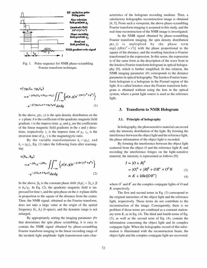
In the above, U�x, y� is the spin density distribution on thex�y plane. b is the coefficient of the quadratic magnetic fieldgradient. W is the impress time. gx and gy are the coefficientsof the linear magnetic field gradients in the x and y direc-tions, respectively. ty is the impress time of gy. txr is theinversion time of gx. J is the magnetogyric ratio.
By the variable transformations kx Jgxtx andky Jgyty, Eq. (1) takes the following form after rearrang-ing:
In the above, E0 is the constant phase shift Jb0�ty � 2txr�. Eis b0 / gx. In Eq. (2), the quadratic magnetic field is im-pressed for time W, and the spin phase on the x�n plane shiftsin proportion to the square of the distance from the center.Then, the NMR signal, obtained as the Fourier transform,does not take a large value at the origin of the spatialfrequency �kx, ky� (k-space), and the dynamic range is notenlarged.
By appropriately setting the imaging parameter JbWthat determines the spin phase scrambling, it is easy tocontain the NMR signal obtained by phase-scramblingFourier transform imaging in the linear recording range ofthe incident light amplitude�light transmission ratio char-
acteristics of the hologram recording medium. Then, asatisfactory holographic reconstruction image is obtained[4, 5]. From such a viewpoint, the above phase-scramblingFourier transform imaging is assumed in this study, and thereal-time reconstruction of the NMR image is investigated.
In the NMR signal obtained by phase-scramblingFourier transform imaging, the spin density distributionU�x, y� is mult iplied by the phase termexp{�jJbW�x2 � y2�} with the phase proportional to thesquare of the distance, and the resulting function is Fouriertransformed in the expression. In this sense, the expressionis of the same form as the description of the wave front inthe lensless Fourier transform hologram in optical hologra-phy [9], which is further simplified. In this relation, theNMR imaging parameter JbW corresponds to the distanceparameter in optical holography. The lensless Fourier trans-form hologram is a hologram in the Fresnel region of thelight. It is called lensless since the Fourier transform holo-gram is obtained without using the lens in the opticalsystem, where a point light source is used as the referencelight.
3. Transform to NMR Hologram
3.1. Principle of holography
In holography, the photosensitive material can recordonly the intensity distribution of the light. By forming theinterference between the object light and the reference light,the phase information of the object light is recorded.
By forming the interference between the object lightscattered from the object O and the reference light R, andrecording the interference fringes on the light-sensitivematerial, the intensity is represented as follows [9]:
where O* and R* are the complex conjugate lights of O andR, respectively.
The first and second terms in Eq. (3) correspond tothe original intensities of the object light and the referencelight, respectively. Those terms do not contribute to thereconstruction of the image. Consequently, there is noproblem if those terms are combined as a constant station-ary term K, as in Eq. (4). The third and fourth terms of Eq.(3), as well as the second term of Eq. (4), contain theinformation concerning the object light and its complexconjugate light. When the holographic record of this infor-mation is illuminated with the reconstruction beam, theobject light and the complex conjugate light are recovered.
Fig. 1. Pulse sequence for NMR phase-scramblingFourier transform technique.
(1)
(2)(3)
(4)
72

3.2. NMR hologram
3.2.1. Amplitude modulation by static
magnetic field offset
Comparing Eqs. (2) and (4) of the signal obtained bythe NMR phase-scrambling Fourier transform imagingmethod, it is seen that the amplitude modulation termexp��jEkx� given by the static magnetic field offset corre-sponds to the plane reference light R in optical holographicrecording. Thus, the operation corresponding to the refer-ence light superposition in the hologram recording processcan easily be realized by shifting the static magnetic fieldfrom the resonance point.
By Eq. (4), the holographic data (NMR hologram)are given as follows:
where Kc is a constant which is defined so that Eq. (5) isalways positive. Kc may be superposed in the computer orby the hardware as a voltage offset. Thus, the NMR holo-gram HNMR can be obtained directly from the NMR signal.
3.2.2. Preprocessing for optical Fourier
transform
The constant Kc, which is given in order to record thewhole waveform of the NMR signal in Eq. (5), appears asthe zeroth-order diffracted light in the optical Fourier trans-form. The Fourier transform pair (optical transfer function)of Kc is a delta function. Ideally, it is a point image, butactually appears as a form with sidelobes due to the effectof the signal truncation. Then, the effect may be superposedon the reconstructed image, which is the first-order light. Itis thus necessary to use an appropriate window function toreduce the effect of the signal truncation and suppress thesidelobe of the zeroth-order diffracted light.
In this case, if the window function is directly appliedto the NMR signal in the k-space, the resolution of thereconstructed image is degraded, due to the fact that themain-lobe width of the optical transfer function of thewindow function is wider than the resolution of the NMRsignal sequence. In order to apply the window functionwithout degrading the resolution, the optical transfer func-tion of the window function is defined as the same as theoriginal resolution of the NMR signal sequence. Moreprecisely, the constant Kc of Eq. (5) is extrapolated to theacquired NMR signal sequence (let it be N u N), to form thedata-complemented k-space Nm u Nm, and then the windowfunction is applied.
Consider the transformation of the NMR signal to theNMR hologram. When the light transmission ratios propor-tional to the signal amplitude are uniformly distributed with
pixel width a and pitch p, the NMR hologram HNMRc takesthe following form (Fig. 2):
Figure 3 shows schematically the process, where thewindow function w is applied to the discrete NMR signalfor the one-dimensional cross section parallel to the kx orky direction. The reconstructed image obtained by the in-verse Fourier transform of Eq. (5) is given by
In the above, F�1 is the inverse Fourier transform. W is theoptical transfer function of w. It is seen from Eq. (7) thatthe reconstructed image is obtained as the direct image andthe conjugate image at the position which is shifted fromthe origin by rE on the focal plane (called off-axis holog-raphy).
In the reconstructed image, the spin density distribu-tion function U multiplied by the second-order phase isconvolved with the optical transfer function W of the win-dow function. Consequently, the phase change in the main-lobe width of W exceeds 2S in the high-frequency region
(5)
Fig. 2. Optical setup for image reconstruction using anLC-SLM.
(6)
(7)
73

where the phase changes rapidly. Then, the signal is aver-aged and the information concerning the spin density is lost.In other words, the main-lobe width of the optical transferfunction W of the window function should at least be of thesame value as the original resolution of the NMR signalsequence. It is desirable that the window function used inthis study have a narrow main-lobe width and a smallsidelobe.
As a window function suited to this purpose, theminimum amplitude moment window is considered. Let thedata matrix in the k-space to which the minimum amplitudemoment window is to be applied, be Nm u Nm. Then, theminimum amplitude moment window w and its opticaltransfer function W are given as follows [10]:
The main-lobe half-value width of Eq. (9) is approxi-mately S /Nmp. The resolution as determined by the finiteNMR signal sequence, that is, the sinc function as theoptical transfer function of the Np u Np rectangular win-dow, has the main-lobe half-value width of S /2Np . Conse-
quently, in order to apply the minimum amplitude momentwindow without degrading the resolution, the data matrixin the k-space, to which the window function is to be appliedin the kx or ky direction, should at least have twice the sizeof the acquired NMR signal sequence.
4. Method and Setup of Experiment
In the image reconstruction experiment, the recon-struction of the still image is tried first, and the possibilityof image reconstruction by the liquid crystal�spatial lightmodulator is examined. Then, the real-time image recon-struction simulation is tried as an experiment. The low-magnetic-field MRI used in the experiment is anexperimental system for small samples, and the imaging isimpossible for a large sample such as the human body.Consequently, the NMR signal from the small phantom isacquired by this low-magnetic-field MRI, and the NMRsignal for the human body is numerically synthesized fromthe NMR images obtained by the general-purpose MRI. Insynthesizing the NMR signal, the spin density data of theNMR image are assigned to the spin density U�x, y� in Eq.(2). Then, multiplying numerically the quadratic phase termcorresponding to the nonlinear magnetic field gradient, thediscrete Fourier transform is applied.
MRI used in the acquisition of the still image gener-ates the static magnetic field of B0 = 0.0192 T by thesolenoid coil (resonant frequency f0 = 819 kHz). Figure 4shows the configuration of the low-magnetic-field MRIused in the experiment. Following the pulse sequence ofFig. 1, the nonlinear magnetic field gradient is applied,being synchronized to the timing of the 90° pulse generator.Then, the linear magnetic field gradient is applied, and theresulting NMR signal is acquired.
In the acquisition of the NMR signal, the static fieldis shifted a little from the on resonance condition, and anadequate constant Kc is superposed to the real part of thesignal so that it is always positive. Then, the holographicdata HNMRc are obtained. The window function is multipliedby HNMRc, and the result is stored in the frame memory ofthe control computer. The data are sent to the liquid crys-tal�spatial light modulator driven by the video (NTSC)signal, and then the NMR hologram is displayed on theliquid-crystal panel. By illuminating the NMR hologram bythe collimated laser light and applying the optical Fouriertransform by the convex lens to the transmitted light, theimage is reconstructed. In the acquisition experiment of thestill image, the reconstructed image is directly recorded onthe photosensitive film through a camera.
The simulation experiment for the real-time recon-struction of the NMR image is executed as follows. Theabove process of synthesizing the NMR signal from thespin density of the NMR image obtained from the general-
Fig. 3. Graphical expression of NMR hologram usingdiscrete NMR signal.
(8)
(9)
74

purpose MRI, is applied to several NMR images, and theholographic data are constructed. Then, a sequence of holo-graphic data are transmitted successively to the liquid crys-tal�spatial light modulator at an interval of 100 ms, whichis nearly the same as the imaging interval in ultrahigh-speedimaging. In imaging the dynamic images, the CCD camera
for the color signal with 380,000 effective pixels is used.The reconstructed dynamic images are recorded by closeupimaging of the image on the screen.
As the liquid crystal�spatial light modulator in theexperiment, the video color liquid-crystal panel for thedisplay of the video projector LZ-P1 (Toshiba) is used.Figure 5 shows an outlook photograph and Table 1 thespecifications.
5. Experimental Results and Discussion
5.1. Still image reconstruction experiment
Figure 5 shows the result of experiment for still imagereconstruction using the low-magnetic-field MRI. Thephantom used in the experiment is an acryl container filledwith water, shown in Fig. 6(a). Figure 6(b) is the NMRhologram constructed from the NMR signal correspondingto Eq. (2). The parameters of the experiment are as follows:JbW = 2 rad/cm2, the repetition time for the pulse sequenceis TR = 300 ms, the resolution is 0.1 cm, and the data matrixof the NMR signal is 64 u 64. In the system used in theexperiment, the slice cannot be selected. Consequently,slice selection is not applied, using the phantom that has thesame structure along the thickness direction.
In order to obtain the holographic data directly fromthe NMR signal, the static magnetic field is a little shiftedfrom the on resonance condition, so that a constant fre-quency offset is provided to the NMR signal in the timereadout direction. The constant term Kc is given by thevoltage offset. As the window function, the minimum am-plitude moment window of Eq. (8) is used. The hologramdata matrix is set as 128 u 128.
Figure 6(c) is the image which is numerically recon-structed by the discrete Fourier transform from the real partof the NMR signal that provides the holographic data.Figure 6(d) is the image which is optically reconstructedfrom the hologram of Fig. 6(b). The reconstructed image(real image) of the phantom, as well as its complex conju-
Fig. 4. Block diagram of the experimental setup for theNMR imaging technique.
Fig. 5. The LC-SLM.
Table 1. Specifications of LC-SLM
75

gate image are seen as the first-order diffracted light. Theoptically reconstructed image well represents the separatorof thickness 2 mm as well as a circular column in thecontainer, of image quality comparable to the image recon-structed by the computer. By applying the window functionto the hologram, the sidelobe of the zeroth-order diffractedlight is suppressed, and there is little image interference.
In the case of the human body, the spin densitydistribution is not uniform as in the phantom. In addition,a larger data matrix is used for the NMR signal in the MRIfor the human body. From such a viewpoint, the holo-graphic reconstruction is attempted for the human image,in order to examine the applicability to the clinical cases.The NMR signal for this purpose is numerically synthe-sized from the NMR image obtained from the MRI for thehuman body.
In order to reduce the sidelobe of the zeroth-orderdiffracted light on the reconstruction plane, the windowfunction should be applied to the NMR signal. Then, inorder to maintain the resolution of the reconstructed image,
the data matrix must be enlarged by extrapolating theconstant Kc of Eq. (5) to the NMR signal as is described inSection 3.2.2. When the extrapolation in the k-space isapplied and if the data matrix of the NMR signal has a largesize, however, not all of the holographic data in the k-spacecan be displayed on the liquid-crystal panel, due to thelimited number of pixels in the liquid-crystal panel. Conse-quently, in the reconstruction experiment for the humanimage, the window function is not used, and the imagingmethod is used so that the image is reconstructed at theposition where the zeroth-order diffracted light does notinterfere.
Our method provides the phase offset proportional tothe amount of the phase encode along the phase encodedirection, in addition to the time readout direction of theNMR signal, so that the reconstructed image is provided ata position deviating from the x and y axes on the reconstruc-tion plane. This manipulation along the phase encode direc-tion can easily be realized by adding a uniform magneticfield pulse in synchronization to the phase encode fieldgradient pulse, and by varying the amplitude by a constantstep.
The NMR signal is synthesized from the NMR imageof 90 u 90 pixels. The hologram data matrix is set as 180 u180. JbW is set as 0.23 rad/cm2. Figure 7 shows the recon-structed image. Panel (a-1) and (b-1) show sagittal andtransversal cross-sectional images used as the spin densitydistribution. Those data are represented by 8-bit gray scalefor 90 u 90 pixels. The NMR signal is synthesized by anoperation corresponding to the phase-scrambling Fouriertransform from the spin density distribution of panels (a-1)and (b-1). Panels (a-2) and (b-2) are the holograms con-structed based on the above data, respectively. It is seenfrom the interference stripe distribution that the low-ampli-tude NMR signals appear after the phase-scramblingFourier transform over a wide range of the k-space.
Panels (a-3) and (b-3) are the respective images re-constructed from the holograms. The images reconstructedby the proposed method almost correctly reproduce theprepared spin density distributions, respectively. As to theresolution, contrast, and image distortion, which are theimportant factors in the image diagnosis, it is seen that S/Nof the image and the resolution are a little degraded. Thereis no problem in particular as to the contrast or imagedistortion, but artifacts of the concentric circular shape aregenerated at the periphery. The major reasons for suchimage degradation are the incompleteness of the opticalsystem and the use of the color liquid crystal. By carefullyconsidering the optical incompleteness and using the mono-chrome liquid-crystal panel, it seems highly probable thatclinically useful images can be reproduced.
Fig. 6. Reconstructed images using alow-magnetic-field imaging apparatus. (a) Phantomstructure; (b) NMR hologram multiplied by window
function; (c) numerically reconstructed image bycomputer-aided method; (d) holographically
reconstructed image.
76

5.2. Simulation experiment for real-time
image reconstruction
The images of relatively high quality are recon-structed for the still images. As the next step, a simulationexperiment is performed for real-time image reconstructionby transmitting the NMR signal to the liquid crystal�spatiallight modulator with a constant time interval, to display thedata. As the NMR signal, the data are synthesized numeri-cally from 15 head coronary cross-sectional multislice im-ages with a slice thickness of 7 mm and a slice interval of10 mm. The obtained NMR signal is sent to the liquid-crys-tal panel with an interval of 100 ms, which is nearly thesame as the imaging interval in ultrahigh-speed imaging.Then, the reconstructed images are dynamic images with aduration of 1.5 s.
Figures 8(ac) to 8(dc) show a part of the reconstructedimages by taking the image on the screen from the CCDcamera and decomposing the images into frames. Thereconstructed image taken by the CCD camera well repro-duces the spin density distributions (a) to (d) for each time
phase. Among the reconstructed images, however, thereexist images which do not correspond to the original spindensity distribution. An example is shown in panel (ec). Itis the image reconstructed in the transition period fromimage (bc) to (cc), that is, the image reconstructed in thedata-update period of the hologram.
Since the optical operation can be executed instantly,the reconstruction operation is also continued during updat-ing of the holographic data. During the period where theholographic data are updated, the image is reconstructedfrom the partial data of the previous and the next images.In other words, a mixed image of two cross sections withadjacent imaging timings is obtained. Observing the mixedimage of Fig. 8(ec), the upper half is similar to panel (bc),and the lower half is similar to panel (cc). The holographicdata are updated from the upper part to the lower. Thehologram, however, is displayed upside down in the experi-ment, and the reconstructed image is updated from thelower side. The above image is a mixed image of differentcross sections, but from the viewpoint of the dynamicimage, the image will be recognized as a very natural
Fig. 7. Reconstructed images using synthesized NMR signal.(a-1) original NMR image (axial)
(a-2) synthesized hologram from NMR image (a-1)(a-3) holographically reconstructed image by hologram (a-2)
(b-1) original NMR image (transverse)(b-2) synthesized hologram from NMR image (b-1)
(b-3) holographically reconstructed image by hologram (b-2)
77

sequence, in contrast to the frame-to-frame display of stillimages, since the transition of the reconstructed imagesprogresses smoothly on the microsecond order, that is, thepixelwise access time.
By the real-time reconstruction simulation experi-ment in this study, it is verified that high-speed reconstruc-tion at an imaging interval of 100 ms can well be realizedin practice. The liquid-crystal panel used in the experimenthas the fast response of the video rate (i.e., 30 frames/s),and can follow the imaging interval of high-speed imaging.The experiment shows that a real-time image reconstructionsystem of simple structure and low cost can be realized.
5.3. Discussion
In this study, the color liquid-crystal panel, which isincluded in the video projector on the market, is used, asthe liquid crystal�spatial light modulator. This liquid-crys-tal panel includes the green and blue pixels, in addition tothe red pixels with a high transmission rate for the He-Nelaser light of 6328 Å. Those pixels reduce the aperture ratioof the liquid crystal for the incident light and can be thesource of the noise light. Consequently, they are not ade-quate for the purpose of this experiment.
On the other hand, the experiment reveals that anNMR image of relatively high quality can be reconstructedusing the color liquid-crystal panel with a smaller numberof pixels. Consequently, it is expected that images of higherquality can be obtained by using a monochrome and highlyprecise liquid-crystal panel. At present, a liquid-crystalpanel of 0.93-inch size with 1024 (horizontal) u 768 (ver-tical) pixels has been developed for the video projector [11].Since the fabrication technology for the liquid-crystal panelis closely related to the fabrication technology for thesemiconductor integrated circuit, it is expected in the futurethat a highly precise liquid crystal with a wide linear record-ing range of the input light�light transmission rate will bedeveloped.
When the NMR image is reconstructed by hologra-phy, a constant frequency-offset is provided to the NMRsignal, in order to separate the real and the imaginaryimages. Because of this procedure, the frequency band(k-space) is required to be at least twice that in ordinaryreconstruction by the computer using the complex NMRsignal. When the number of data are increased along thephase encode direction, in order to enlarge the frequencybandwidth, the number of pulse sequence iterations in Fig.1 is increased, which is disadvantageous since the measure-ment time is increased. In the image reconstruction experi-ment, it is noted that the number of pixels is lower in theliquid-crystal panel. As a method not using the windowfunction, while minimizing interference between the recon-structed image and the zeroth-order diffracted light withoutdegrading the resolution, the reconstructed image is shiftedby providing a phase offset proportional to the phase en-code, along the phase encode direction of the NMR signal.If there are a sufficient number of pixels in the liquid-crystalpanel, however, it suffices to provide the frequency offsetonly along the time readout direction. In this case, bydoubling the sampling rate without changing the samplinglength, the frequency band can be doubled without increas-ing the measurement time.
Compared to the reconstruction by computer thatreconstructs the image from the complex NMR signal, onlythe real part is used in the holographic reconstruction. Then,the S/N ratio of the image is reduced by a factor of 1 /�CC2,in principle. In this experiment, the liquid-crystal panel is
Fig. 8. Simulation results of a real-time reconstructionof NMR images.
78

used as the amplitude modulation element for the incidentlight. There is also a study of the ideal spatial light modu-lator, on the other hand, where two liquid-crystal panels arecombined as the amplitude and the phase modulation ele-ments, respectively, so that both the phase and the ampli-tude of the light wave are controlled [12]. This technique isstill in the stage of verification of the principle. If realized,there will be holography which can reconstruct only the realimage with the same image S/N as that of the imagereconstructed by the computer.
The NMR image reconstructed by the optical analogtechnique is worse than the image reconstructed by thecomputer, in terms of the accuracy of the computation.When the image is to be displayed as a three-dimensionalimage, or the real-time dynamic images are to be recon-structed, it is difficult to use the digital technique where thefinal output is the two-dimensional image, and an analogtechnique such as holography must be applied. We plan toinvestigate what type of characteristic magnetic field gen-eration system should be used, to acquire an NMR signalthat can realize three-dimensional image reconstructionholography. If a pulsating object of imaging such as theheart can be imaged as a real-time three-dimensional image,it will be very useful, since the body�s medical informationcan then be monitored noninvasively.
6. Conclusions
As a basic study on real-time reconstruction of theNMR image, an experiment for the holographic reconstruc-tion of the NMR image is performed, where the hologramis constructed from the NMR image obtained by the NMRphase-scrambling Fourier transform method, and is dis-played by the liquid crystal�spatial light modulator. It isverified that an image of relatively high quality can beobtained by using the color liquid-crystal panel on themarket with a lower number of pixels. Then, the high-speedprocessing of the proposed method is noted, and a simula-tion experiment is performed for the real-time image recon-struction, being combined with the high-speed imagingprocedure. It is verified that high-quality dynamic imagescan be reconstructed with an imaging interval of 100 ms.
From our experiments, it is shown that the proposedmethod, which is based on the similarity of the diffractionformula and the NMR signal, and reconstructs the NMRsignal by the holographic procedure, has the possibility ofreal-time image reconstruction. The authors plan to inves-
tigate the real-time method that reconstructs the image, inparallel to the acquisition of the NMR signals, as well asthe three-dimensional image reconstruction.
Acknowledgments. Part of this study was sup-ported by Konica Image Sci. Found., as well as a Grant-in-Aid for Sci. Res., Min. Educ. (1996, Encour. A, 08750047).The authors also thank Mr. K. Sato, Shonan Inst. Tech., foradvice in the use of the liquid-crystal panel.
REFERENCES
1. Mansfield P. Multi-planar image formation usingNMR spin echos. J Phys C 1977;10:L55�L58.
2. Kose K, Haishi T. Development of a real-time MRimage reconstruction system using a high-speed mi-croprocessor. JMRM 1996;16:98�102.
3. Gmitro AF, Ehsani AR, Berchem TA, Snell RJ. Areal-time reconstruction system for magnetic reso-nance imaging. Magn Reson Med 1996;35:734�740.
4. Yamada Y, Ito S, Tanaka K. Holographic reconstruc-tion of NMR images in Fresnel transform technique.Trans IEICE 1989;J72-C-I:855�861.
5. Ito S, Sato O, Yamada Y, Kamimura Y. Reconstructionof NMR images via holograms displayed on a liquidcrystal�spatial light modulator. ITE Tech Rep1995;19:7�10.
6. Maudsley AA. Dynamic range improvement in NMRimaging using phase scrambling. J Magn Reson1988;76:287�305.
7. Wedeen VJ, Chao Y, Ackerman JL. Dynamic rangecompression in MRI by means of a nonlinear gradientpulse. Magn Reson Med 1988;6:287�295.
8. Turner R. Optical reconstruction of NMR images. JPhys E 1985;18:875�878.
9. Stroke GW. An introduction to coherent optics andholography. Academic Press; 1969.
10. Papoulis A (translated by Machida T, Murata T).Signal analysis. Gendaikogakusha Co.; 1982.
11. Pioneer Catalog. Data-responding highly-precise liq-uid-crystal projector XG1. Pioneer Co.; July 1996.
12. Amako J, Miura H, Sonehara T. Wave-front controlusing liquid-crystal devices. Appl Opt 1993;32:4323�4329.
79

AUTHORS (from left to right)
Satoshi Ito (member) graduated from the Department of Electrical Engineering, Utsunomiya University, in 1987 andcompleted the Electrical Engineering course, Graduate School of Engineering, in 1989. He then joined Toshiba Corp. He becamean assistant in the Department of Information Science, Utsunomiya University, in 1994. His research interests are holographicreconstruction and real-time reconstruction of NMR images. He is a member of JSMEBE, JMRM, and the Optical Society ofJapan.
Yoshitsugu Kamimura (member) graduated from the Department of Electrical Engineering, Nagoya University, in 1980and completed the doctoral program in 1985. He then joined the Ministry of Posts & Telecommunications. He became a lecturerin the Department of Information Science, Utsunomiya University, in 1991 and an associate professor in 1994. His researchinterests are NMR measurement of deep body temperature, biological information acquisition, and biological electromagneticenvironment. He holds a D.Eng. degree. He received a Shinohara Encouragement Award in 1988 from IEICE. He is a reviewerfor IEICE, and a member of IEEJ, JSMEBE, the Biophysics Society of Japan, the Japan Society of Health Physics (a memberof planning committee), the Japan Society of Hypertherm. Oncology, and IEEE.
Yoshifumi Yamada (member) completed the doctoral program (electrical and information engineering) at TohokuUniversity in 1971 and then joined the Faculty of Engineering. In 1974, he became a lecturer at Hokkaido University. He movedto Utsunomiya University, becoming an associate professor in the Department of Electrical Engineering in 1979 and a professorin the Department of Information Science in 1990. His research interests are medical information processing, new NMR imagingmethod, and optical reconstruction of NMR images. He holds a D.Eng. degree. He is a member of JSMEBE, the Society ofInstrument and Control Engineers, JMRM, IEEE, and ISMRM.
80