realising the principle: time is money - airdusco inc · allowed execution of the 2 process steps...
TRANSCRIPT

An important chance for optimising the productivity in rolling mills consists of combining single processes in an efficient and reliable manor. Referring to that approach, the 2 photos on this page show a 15 t crane spreader beam before and after the weighing modernisation. This crane is used to transport finished or collected wire rod bar bundles to the sales stockyard. Installing a SCHENCK scale inside the spreader beam has allowed execution of the 2 process steps “Transport” and “Legal for Trade Weighing” more or less simultaneously. The former additional step “Positioning of the bundle onto a separate platform scale” has been eliminated. The saving in time directly leads to an increase of productivity of the “Crane Transport “ that often represents a bottleneck in the Rolling Mill production.
Heavy Industry 11.2005 GB
Realising the principle: Time is money
Modernisation of Weighing in rolling mills
08.0
5.4
00.
We r
eserv
e t
he r
ight to
dis
continue o
r change s
pecific
ations a
t any tim
e.
BEFORE
AFTER

Measuring and Process Technologies
SCHENCK PROCESS GmbH
D-64273 Darmstadt
Telefon: +49 (0) 61 51-32 - 3625
Telefax: +49 (0) 61 51-32 - 3270
E-Mail [email protected]
www.schenck-process.de
BV
-A102
0G
B
XB
S 0
8.0
5.4
00.
We r
eserv
e th
e r
ight
to d
iscontinu
e o
r chan
ge
specific
ations a
t any tim
e w
itho
ut n
otice o
r o
blig
ation
.
The photo to the right side explains the working principle of the tailor-made crane scale: by completely separating the sheave block from the spreader beam body we integrated a direct and entire load transmission over 2 x 2 Loadcells RTN 10 t with Elastomer Mounts VEN 10. The arrangement of the Loadcells at the sides of the beam generated the following design and operation advantages: - The working height of the spreader beam remained
unaltered; - Mechanically, the Loadcells were well protected; - The bumpers and hold-downs were well accessible,
controllable and adjustable The next 2 photos show a very similar integration of a weighing system in the transportation process:
It concerns a raising platform car working at the logistical interface between the crane transport of coil bundles from the annealing furnace and the forklift transport to the dispatching area. Also, at this location the costumer formerly used a separate platform scale for Legal-for-Trade weighing. The new coil bundle scale has a weighing range of 5 t. It was designed with 4 x RTN 4,7 C3 Loadcells, 4 x VEN 4,7 Elastomer Mounts and reinforced horizontal bumpers and hold-downs for the safe transmission of the dynamic loads during charging. These examples show, that in the Rolling Mill usually “Legal for Trade” scales are required. This is an important difference from the other areas of steel plant, where especially “process or internal weighing systems” are installed. This application difference is due to the fact, that the weighing results in the Rolling Mill are used for invoicing, for example in contracts with external steel trade com-panies. Those scales used for commercial invoicing must follow the national legalisation rules. That implies for example the following conditions: - The weighing components installed inside must
have an official type test, for example certified by the PTB in Braunschweig.
- The scale must achieve clearly defined operational specific weighing tolerances (during initial verification and operation).
Please find the tolerances for the initial verification for the raising platform scale illustrated on this page with a Weighing Range of 5 t and an increment value of 2 kg (representing a legal for trade resolution of 2.500 digits): Test load 40 kg ...1t: max. weighing error ± 1 kg Test load 1 t .… 4t: max. weighing error ± 2 kg Test load 4 t .… 5t: max. weighing error ± 3 kg After the successful initial verification, the scales have to respect in operation the so-called in-service accuracy tolerances until the next verification date. They allow the double weighing error in relation to the initial verification. SCHENCK uses Rolling Mills Loadcells RTN with a Rated Capacity between 1 - 47 t and accuracy classes up to 5.000 digits in combination with the Weighing Terminal Disomat Bplus for these Legal-for-Trade scales.
BEFORE AFTER
12.0
5.40
0. W
e re
serv
e th
e rig
ht to
dis
cont
inue
or c
hang
e sp
ecifi
catio
ns a
t any
tim
e.
When in NetherlandWeighbeainside a indeed anweighing been creaAt the occthe HI - Nadvantagelooking foworking p As a first two differsystem: ExecutioSupport omounts, hold-down
Heavy Industry 12.2005GB
p
20 years SCHENCK – Direct Weighing Technologies:
summer 1985 at Hoogovens in the s for the first time SCHENCK -
ms had been commissioned successfully ladle turret, it was quickly proven, that innovative new technology for various applications in the heavy industries had ted. asion of this jubilee the today´s edition of ews points out the essential features and s of SCHENCK - Direct Weighing, always r new beneficial applications in your
rocesses.
example we would like to present to You ent executions of a special bin weighing
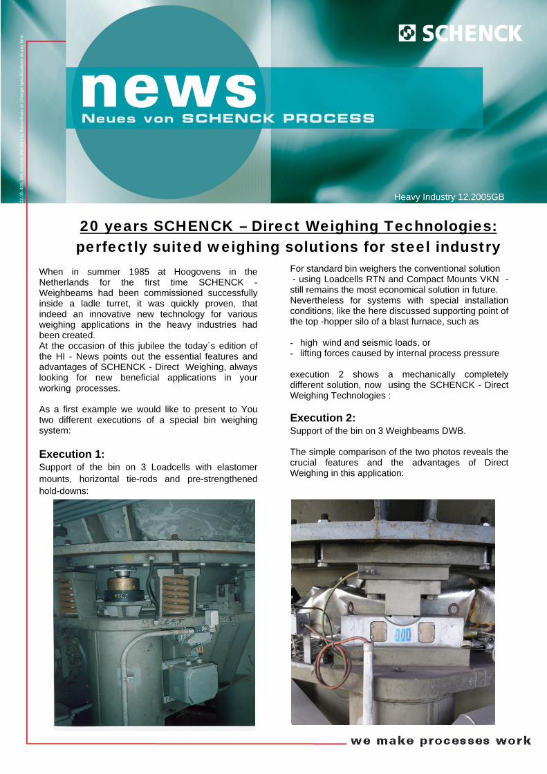
n 1: f the bin on 3 Loadcells with elastomer horizontal tie-rods and pre-strengthened s:
erfectly suited weighing solutions for steel industry
For standard bin weighers the conventional solution - using Loadcells RTN and Compact Mounts VKN - still remains the most economical solution in future. Nevertheless for systems with special installation conditions, like the here discussed supporting point of the top -hopper silo of a blast furnace, such as - high wind and seismic loads, or - lifting forces caused by internal process pressure
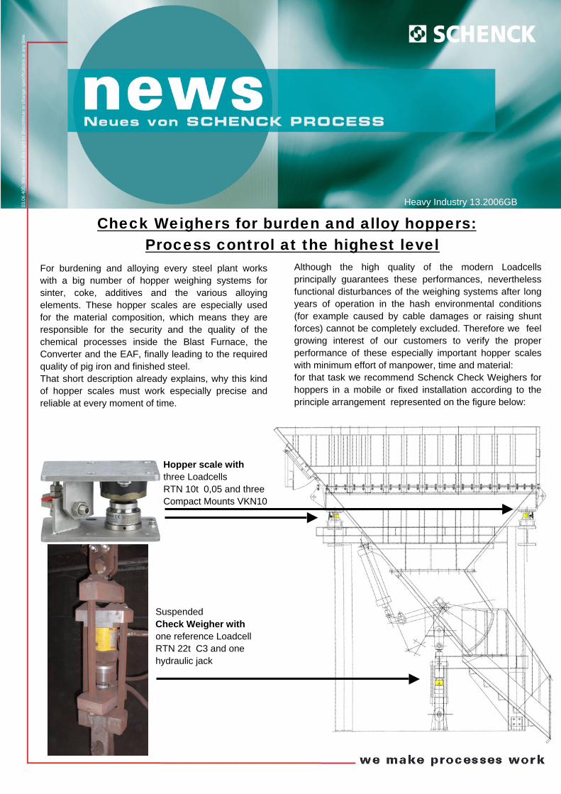
execution 2 shows a mechanically completely different solution, now using the SCHENCK - Direct Weighing Technologies : Execution 2: Support of the bin on 3 Weighbeams DWB. The simple comparison of the two photos reveals the crucial features and the advantages of Direct Weighing in this application:

At each of the three supporting points one Weigh- beam DWB is simply screwed - from the bin suspension ring and - to the steel foundation. The major difference to execution 1 is based on the principle, that absolutely no further supporting elements between the bin and the ground are required anymore, leading straight to the following advantages: - no shunt forces, that especially on the long term operation are difficult to manage,
- no moving parts, - no mechanical adjustment works,
- for the mechanical installation no special training is needed,
- the weighing system based on Weighbeams works entirely maintenance-free and insensitive against dirt or dust pollution.
Obviously many internal process weighing systems can be executed in an easier and finally more reliable manner using SCHENCK -Direct Weighing Technologies. Problems with blocked tie-rods, hold-downs or closed bumper gaps will disappear for all times!
Measuring and Process Technologies
SCHENCK PROCESS GmbH D-64273 Darmstadt Telefon: +49 (0) 61 51-32 - 3625 Telefax: +49 (0) 61 51-32 - 3270 E-Mail [email protected] www.schenck-process.de
BV
-A10
21G
B X
BS
12.0
5.40
0. W
e re
serv
e th
e rig
ht to
dis
cont
inue
or c
hang
e sp
ecifi
catio
ns a
t any
tim
e w
ithou
t not
ice
or o
blig
atio
n.
As second example for an economical and successful installation of SCHENCK-Direct Weighing please find below two photos of three new built scrap trailers with a total gross weight of 120 t each. The weighing system installed simply consists of 4 Weighbeams DWB 50t in a double frame arrangement. Different from the conventional solution for such a weighing double frame (using Loadcells RTN, Elastomer mounts VEN, external bumpers and hold-downs), also in this case the Weighbeams have been simply screwed between the upper weighing frame and the trailer wheel base frame. In the heavy and dirty surrounding of the scrap yard this solution contains several advantages: For the manufacturer of the trailor:
- easy design using standardised sensors, - easy and quick commissioning due to the
minimised number of parts. For the final costumer in the steel plant:
- highly minimised shunt forces by dirt and dust, - high accuracy with a deviation during scrap
loading of less than ± 300 kg, - high mechanical stability of the dynamic load
transmission during scrap loading.
Schenck - Direct Weighing Technologies:
The simple solution without compromise!
03.0
6.40
0. W
e re
serv
e th
e rig
ht to
dis
cont
inue
or c
hang
e sp
ecifi
catio
ns a
t any
tim
e.
For burdeningwith a big nusinter, coke, elements. Thefor the materresponsible fochemical proConverter andquality of pig iThat short deof hopper scareliable at eve
Heavy Industry 13.2006GB
Check Weighers for burden and alloy hoppers:Process control at the highest level
and alloying every steel plant works mber of hopper weighing systems for additives and the various alloying
se hopper scales are especially used ial composition, which means they are r the security and the quality of the
cesses inside the Blast Furnace, the the EAF, finally leading to the required
ron and finished steel. scription already explains, why this kind les must work especially precise and
ry moment of time.
Hopper scale with three Loadcells RTN 10t 0,05 and three Compact Mounts VKN10
Suspended Check Weigher with one reference Loadcell RTN 22t C3 and one hydraulic jack
Although the high quality of the modern Loadcells principally guarantees these performances, nevertheless functional disturbances of the weighing systems after long years of operation in the hash environmental conditions (for example caused by cable damages or raising shunt forces) cannot be completely excluded. Therefore we feel growing interest of our customers to verify the proper performance of these especially important hopper scales with minimum effort of manpower, time and material: for that task we recommend Schenck Check Weighers for hoppers in a mobile or fixed installation according to the principle arrangement represented on the figure below:
BV
-A10
22D
E X
BS
03.0
6.40
0. W
e re
serv
e th
e rig
ht to
dis
cont
inue
or c
hang
e sp
ecifi
catio
ns a
t any
B
V-A
1022
DE
XB
S 03
.06.
400.
Alle
Ang
aben
sin
d un
verb
indl
ich.
Änd
erun
gen
blei
ben
vorb
ehal
ten.
tim
e
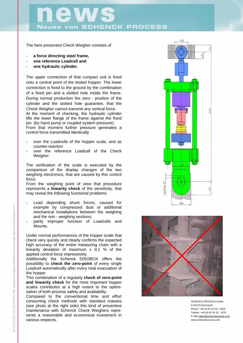
The here presented Check Weigher consists of - a force directing steel frame, - one reference Loadcell and - one hydraulic cylinder.
The upper connection of that compact unit is fixed onto a central point of the tested hopper. The lower connection is fixed to the ground by the combination of a fixed pin and a slotted hole inside the frame. During normal production the zero - position of the cylinder and the slotted hole guarantee, that the Check Weigher cannot transmit any vertical force. At the moment of checking, the hydraulic cylinder lifts the lower flange of the frame against the fixed pin (by hand pump or coupled system pressure). From that moment further pressure generates a control force transmitted identically - over the Loadcells of the hopper scale, and as
counter-reaction - over the reference Loadcell of the Check
Weigher. The verification of the scale is executed by the comparison of the display changes of the two weighing electronics, that are caused by this control force. From the weighing point of view that procedure represents a linearity check of the sensitivity, that may reveal the following functional problems: - Load depending shunt forces, caused for
example by compressed dust or additional mechanical installations between the weighing and the non - weighing sections;
- partly improper function of Loadcells and Mounts.
Under normal performances of the hopper scale that check very quickly and clearly confirms the expected high accuracy of the entire measuring chain with a linearity deviation of maximum ± 0,1 % of the applied control force impressively. Additionally the Schenck DISOBOX offers the possibility to check the zero-point of every single Loadcell automatically after every total evacuation of the hopper. This combination of a regularly check of zero-point and linearity check for the most important hopper scales contributes at a high extent to the optimi-sation of both process safety and availability. Compared to the conventional time and effort consuming check methods with standard masses (see photo at the right side) this kind of preventive maintenance with Schenck Check Weighers repre-sents a reasonable and economical investment in various respects.
SCHENCK PROCESS GmbH D-64273 Darmstadt Phone: +49 (0) 61 51-32 - 3625 Telefax: +49 (0) 61 51-32 - 3270 E-Mail [email protected]

05.06.400. We reserve the right to discontinue or change specifications at any time.
Heavy Industry 14.2006
schenckservices for Weighing and Dosing systems:
much more than installation and commissioning
In the harsh environment of the various weighing and dosing systems operating in steel industry excellent product properties and a close co-operation between Schenck Process and its world wide partners in all service matters are essential in order to guaran-tee a maximum of accuracy and realiability.
Considering the high pressure on efficiency in steel production with constantly growing targets Schenck Process has started a special program to strengthen co-operation with the weighing specialists in the steel plants, following the objectives listed above:
- higher availability and realiability by using modern features for preventive maintenance
- quicker information exchange and industrial
realisation of innovation and field-experiences in
mechanics, electronics, fieldbus technologies and
maintenance
- intensivation of the contact in terms of quality assurance acording to DIN ISO
On the next page we like to present some of our service product ideas, at the same time kindly asking from You a short feed-back by Fax or Mail return:

BV
-A10
23G
B X
BS
03.0
6.40
0. W
e re
serv
e th
e rig
ht to
dis
cont
inue
or c
hang
e sp
ecifi
catio
ns a
t any
tim
e
1. Are You able to analyse every Loadcell? If You are responsible for extremely process sensitive weighing systems in 24 hour operation, we recom-mend to reduce the consequences of eventual damages by preventive maintenance in time! Installing the DISOBOX instead of the conventional junction boxes enables the maintenance staff to check in the control room every single Loadcell additionally to the total weight display. More detailed information allows to activate an emergency mode by simple electronic adjustment assuring the scale operation. For Your training our completely pre-assembled DISOBOX-Base-Package is available at stock.
2. Do You know the precise weight of Your calibration ladles? Specialists know, that this is a difficult question, although the calibration ladles used for the electroni-cal adjustment of all crane, ladle car and turret scales play an important role for precise mass balancing of the steel production. We are planning to weigh Your calibration ladles at site using a special Control Measurement Device. Afterwards You will be able to answer the above question convincingly …
3. Teamwork makes us stronger! Sophisticated downloads, modernisation of old electronics, regular information about new products, certified training for new colleagues, held in-plant or at a close Schenck Location as well as personalised telephone support: with our new service package we want to recommend ourselves - even more than in the past - as first partner of the weighing and dosing specialist in the steel plants!
4. Always in trouble because of weighing mechanics? Have You been bothered for long time by older weighing systems not properly working anymore for any mechanical reasons? We offer to investigate these scales at site, followed by an engineering report containing modification proposals, based on our experience with steel plant weighing systems world wide. Could we attract Your interest? Or do You have further areas in mind, where further Schenck service assistance would be appreciated?
se
DISOMAT Bplus/PLC
Loadcells/ Weighbeams
DISOBOX
rvices
Installation Engineering
Control Measurement Device
Training
Spare Parts Maintenance
Modernisation
Commissioning
Please give us a short feed-back to these questions: Service products: Interesting? yes / no 1. Are You able to analyse every Loadcell? / 2. Do You know the precise weight of Your calibration ladles? / 3. Teamwork makes us stronger! / 4. Always in trouble for weighing mechanics? /
Your comments and additional suggestions:
Your name: Country: Your company: City: Mail address: Please re-send that page after completion to: Fax: +49 (0)6151 32-3270 or [email protected] Thank You very much for Your assistance, our Service department will contact You!

09.06.400. We reserve the right to discontinue or change specifications at any time.
Heavy Industry 15.2006
A new member of the DISOMAT® family:
the DISOMAT® Opus
The latest edition of the DISOMAT® family demon-strates, that legal-for-trade logistic solutions today can be realised very cost-effectively. The development of this new product was carried out based of the proven DISOMAT® B plus Weighing Terminal. Thanks to the comprehensive communication facilities our new device can be easily integrated into data-processing and control systems such as MPC, PC or others. Whether conventional I/O, industrial fieldbus or USB interfaces are required: the DISOMAT® Opus is at home in every environment and even includes an integral on-board Ethernet port. The heart of the DISOMAT® Opus is the new 32 Bit ARM controller, which offers more than enough per-formance reserves for quick weighing processes and the simultaneous operation of several interfaces. The DISOMAT® Opus is perfectly suited for all appli-cations, in which weight values must be recorded in legal-for-trade operation, displayed, printed out and transmitted to higher level automation systems for further processing. It can cover a wide range of differ-ent process applications, such as:
platform scales hopper scales level monitoring systems truck scales crane scales single component dosing systems
For user-friendly adjustment the DISOPLAN® graphic user interface enables quick and easy adaptation of the operation and print format, calibration, back-up and restore functions. These are perfect conditions for an optimal replace-ment of the proven weighing indicator DISOMAT® F. Summarised main technological features of the latest multi-talent electronics offspring of the DISOMAT® family are:
legal-for-trade approval (6000d, multi-range and multi-division scale up to 3x 4000d)
stainless steel housing integrated legal-for-trade memory (optional) intelligent Loadcell plug (dongle) on-board Ethernet interface
(Profibus, DeviceNet available as options) USB-interface for external keyboard parameter adjustment via customer network
(DISOPLAN® via Ethernet)
Small, compact and very cost-effective - a leading concept for today’s and future applications, that will certainly pay-off for our customers.

The DISOMAT® family –
BV
-A10
24G
B X
BS
.4
00. W
e re
serv
e th
e rig
ht to
dis
cont
inue
or c
hang
e sp
ecifi
catio
ns a
t any
tim
e w
ithou
t not
ice
or o
blig
atio
n.
09.0
6 Year: 1978 1980 1982 1984 1986 1988 1990 1992 1994 1996 1998 2000 2002 2004 2006 ...
DISOMAT® Opus
DISOMAT® F DISOMAT® F
DISOMAT® T
DISOMAT® C DISOMAT® C
DISOMAT® P DISOMAT® P
DISOMAT® E DISOMAT® E
DISOMAT® D DISOMAT® D
Schenck Process GmbH Pallaswiesenstr. 100 64293 Darmstadt, Germany T +49 6151 32-3625 F +49 6151 32-3270 [email protected] www.schenckprocess.com
Living time
Spare part availability
Recommended replacement product
DISOMAT® K DISOMAT® K
DISOMAT® M2 & M3 DISOMAT® M2 & M3
DISOMAT® M1 DISOMAT® M1
DISOMAT® B DISOMAT® B
DISOMAT® S DISOMAT® S
DISOMAT® B plus
in the past and today Schenck weighing electronics have been introduced in the market since the 70th. The first unit brand names were: PIKOMAT®, DFM®, DIKOMAT®, GDM® and DISOMAT® 7S. The graph below shows all following weighing electronic generations starting from the production year 1978:
With this presentation we like to give to You an
ment here only are a general
Anwendungsfall zutreffend.
overview about the life-cycle of all our devices for static weighing. At the same time it visualises crucially the general technological progress in electronics up to today´s state of the art.
Our proposals for replaceguideline.Please contact us directly in order to define in all details the optimal modern electronics for every single application.
Sprechen Sie un
01.07.400. We reserve the right to discontinue or change specifications at any time. Heavy Industry 16.2007
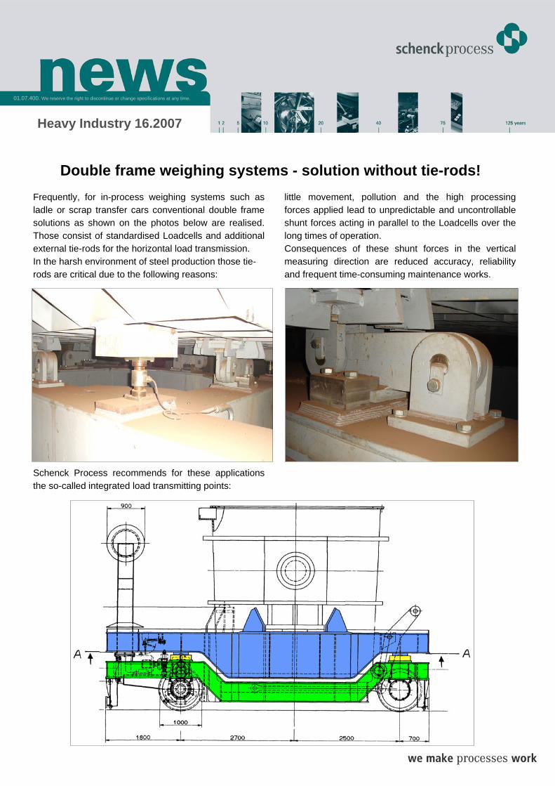
Double frame weighing systems - solution without tie-rods! Frequently, for in-process weighing systems such as ladle or scrap transfer cars conventional double frame solutions as shown on the photos below are realised. Those consist of standardised Loadcells and additional external tie-rods for the horizontal load transmission. In the harsh environment of steel production those tie- rods are critical due to the following reasons:
Schenck Process recommends for these applications the so-called integrated load transmitting points:
little movement, pollution and the high processing forces applied lead to unpredictable and uncontrollable shunt forces acting in parallel to the Loadcells over the long times of operation. Consequences of these shunt forces in the vertical measuring direction are reduced accuracy, reliability and frequent time-consuming maintenance works.

The graphics of a ladle transfer car with double frame shown on the previous page clearly visualises, that between the “blue” weighing frame and the “green” base frame apart of the “yellow” load transmitting points no further design elements are needed. This execution eliminates the described negative shunt force influ-ences completely. Each of the four loading points is composed according to the graphics on the right side by one Weighbeam DWB completely fixed inside the steel structure, enabling to transmit additionally to the vertical measuring weight
BV
-A10
25G
B X
BS
09.
06.4
00. W
e re
serv
e th
e rig
ht to
dis
cont
inue
or c
hang
e sp
ecifi
catio
ns a
t any
tim
e w
ithou
t not
ice
or o
blig
atio
n.
- all horizontal loads and - lifting forces,
applied for example during the set-in of the ladle. Apart from the Weighbeams, those integrated load transmission points in double frames nowadays can also be realised using the Schenck Process Weighdisc WDI, that contains especially in case of limited space conditions further advantages. The graphics below dis-plays such an integrated loading point, that in the same manor as described before is able to transmit all hori-zontal forces applied without negative effects on the weighing accuracy. For easy assembly, this solution is executed by simply laying the “blue” weighing frame on the weighing load point. An additional external hold-down completes the very maintenance-friendly design.
The photo on the right side shows a similar type of an integrated loading point, used for crane scales in
double frame or hopper scales as well, achieving an accuracy of up to ± 0.1 % of Full Scale in operation. These examples demonstrate, that for new installations and revamping of in-process scales modern weighing solutions allow to renounce in conventional tie-rods: a valuable contribution to increase accuracy and at the same time to reduce maintenance costs and effort. If in Your plant double frame weighing systems with tie-rods are still operative in the described areas, we would be pleased for any contact to check the improvement chances for the future operation of these scales. Zunäch
Schenck Process GmbH Pallaswiesenstr. 100 64293 Darmstadt, Germany T +49 6151 32-3625 F +49 6151 32-3270 [email protected]

from: MPT International Metallurgical Plant and Technology, Issue 6, November 2006
Advanced in-process weighing systems for steel production: accurate and reliable by maintenance-free design
press–press–press–press–press
Sonderdruck – Reprint

press–press–press–press–press press–press–press–press–press
IntroductionThis article provides to production and maintenance depart-
ments of steel plants and to plant designers an overview
over advanced weighing systems, used for example for
liquid steel or scrap weighing, that offer high accuracy and
reliability combined with crucially reduced time and money
effort for maintenance.
Considering the trend of down-sizing maintenance depart-
ments going on in parallel with the steadily increasing
requirements on productivity, all design improvements,
that reduce maintenance on weighing systems, contain a
high economical potential. Over the last years the following
mechanical features have been developed and successfully
executed especially for the various in-process weighing
applications:
design of special strain gauge Load cells,
defi nition of best suited installation places for the weigh-
ing mechanics,
continuous exploitation of fi eld experience with installed
systems worldwide as technical reference.
The totality of these elements contribute to the fact, that
modern in-process weighing systems operate extremely
accurate and reliable in the harsh environment of steel
production, that is characterised by huge dynamic forces,
high temperatures, signifi cant contamination by dust and
spillages as well as extremely restricted maintenance and
repair access.
The tasks of in-process weighing systemsMore than ever before today’s worldwide consolidation of
steel industry is followed by the constant need for process
improvement. Weighing systems have always largely
contributed to economical and safe steel production: from
the mass control and dosing of raw materials over the
processing of hot metal and steel to the sale of fi nished
products. Especially the in-process weighing systems, used
for the internal control in the production area (scrap yard,
Blast Furnace, Converter, EAF and Continuous Casting Ma-
chine) have to operate in an extremely harsh environment.
With loads to be weight between 1 and 1,000t, these kind of
scales should be mechanically designed for every particular
use, leading frequently to solutions very different from con-
ventional legal-for-trade scales like truck or platform scales.
In-process weighing systems generally are used for the
following functions of the steel plant management:
production control for stable quality parameters,
determination and optimisation of the Yield inside one
production unit,
internal plant mass balancing, “invoicing” of services and
production turnover between different production units.
Additional to these control functions reliable weighing
systems contribute signifi cantly to increase safety and
profi tability of the daily steel making process.
Safety:Where large amounts of liquid hot metal and steel have to be
transported between different processing areas, weighing
equipment has an essential, safety-critical function in order
to avoid spillages and accidents, for example during the
weight-controlled fi lling of ladles. Only weighing systems
that operate without any contact to the dangerous products
can guarantee the necessary process safety.
Profi tability:Precise weighing systems crucially improve the profi tability,
allowing to feed the minimum of raw materials and alloys
to achieve the desired steel quality respecting the chemical
tolerances. An easy calculation example may demonstrate
the huge benefi t: an annual production of 1 Mio t alloyed
steel should contain a fi nal Molybdenum content of minimum
0.45 %. The net steel mass as reference for the alloy calcula-
tion may be weight in a ladle transfer car or the overhead
transport crane scale. Assuming that this scale fi rst operates
inside the unsatisfying error limits ± 1 % of Full Scale, please
fi nd the calculation of the required annual Molybdenum
mass:
Correct weight 1: Wc1 =1,000,000 t
Displayed weight 1: Wd1 = 990,000 t – 1,010,000 t
In order to guarantee the fi nal alloy percentage in the melt
the calculation of the alloy mass must refer to the maximum
displayed weight:
Required alloy mass 1:
Ma1 = 0.45 % * 1,010,000 t / a = 4,545 t / a
Improving the weighing system performance to respect
error limits ± 0.2 % of Full Scale leads to the following result:
Correct weight 2: Wc2 = 1,000,000 t
Displayed weight 2: Wd2 = 998,000 t – 1,002,000 t
Required alloy mass 2:
Ma2 = 0.45 % * 1,002,000 t / a = 4,509 t / a
The difference of 36 t Molybdenum (Ma1 – Ma2) represents
an annual saving of about 1.5 Mio EUR. It is self-evident, that
taking into account all different alloying elements multiplies
that benefi t. This simple example confi rms convincingly,
that precise and stable operating weighing systems are an
effi cient tool to increase the profi tability of steel produc-
tion. Additionally, availability of information about the
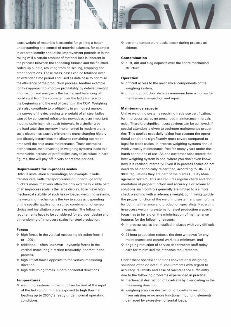
exact weight of materials is essential for gaining a better
understanding and control of material balances, for example
in order to identify and utilise improvement potentials: in the
rolling mill a certain amount of material loss is inherent in
the process between the annealing furnace and the fi nished,
coiled-up bundle, resulting from de-scaling, cropping and
other operations. These mass losses can be totalised over
an extended time period and used as data base to optimise
the effi ciency of the production process. Another example
for this approach to improve profi tability by detailed weight
information and analyse is the tracing and balancing of
liquid steel from the converter over the ladle furnace to
the beginning and the end of casting in the CCM. Weighing
data also contribute to profi tability in an indirect manor:
the survey of the decreasing tare weight of all steel ladles
caused by consumed refractories nowadays is an important
input to optimise their repair intervals. In a similar way
the load totalising memory implemented in modern crane
scale electronics exactly mirrors the crane charging history
and directly determines the allowed remaining operation
time until the next crane maintenance. These examples
demonstrate, than investing in weighing systems leads to a
remarkable increase of profi tability, easy to calculate in hard
fi gures, that will pay-off in very short time periods.
Requirements for in-process scalesDiffi cult installation surroundings, for example in ladle
transfer cars, ladle transport cranes or under huge scrap
buckets mean, that very often the only externally visible part
of an in-process scale is the large display. To achieve high
mechanical stability of such heavy loaded weighing systems,
the weighing mechanics is the key to success: depending
on the specifi c application a suited combination of sensor
choice and installation place is essential. The following
requirements have to be considered for a proper design and
dimensioning of in-process scales for steel production:
Forces high forces in the vertical measuring direction from 1
to 1,000 t,
additional – often unknown – dynamic forces in the
vertical measuring direction frequently inherent in the
process,
high lift-off forces opposite to the vertical measuring
direction,
high disturbing forces in both horizontal directions.
Temperatures weighing systems in the liquid sector and at the input
of the hot rolling mill are exposed to high thermal
loading up to 200 °C already under normal operating
conditions,
extreme temperature peaks occur during process ac-
cidents.
Contamination dust, dirt and slag deposits over the entire mechanical
structure.
Operation diffi cult access to the mechanical components of the
weighing system,
ongoing production dictates minimum time windows for
maintenance, inspection and repair.
Maintenance aspects Unlike weighing systems requiring trade use certifi cation,
for in-process scales no prescribed maintenance intervals
exist. Therefore signifi cant cost savings can be achieved, if
special attention is given to optimum maintenance proper-
ties. This applies especially taking into account the opera-
tional conditions signifi cantly more severe compared to
legal-for-trade scales. In-process weighing systems should
work virtually maintenance-free for many years under the
harsh conditions of use. As one customer once stated: the
best weighing system is one, where you don’t even know,
how it is realised internally! Even if in-process scales do not
need do be periodically re-certifi ed, according to DIN ISO
9001 regulations they are part of the plants Quality Man-
agement System. This use requires regular check and docu-
mentation of proper function and accuracy. For advanced
solutions such controls generally are limited to a simple
check weighing with a reference weight, confi rming quickly
the proper function of the weighing system and saving time
for both maintenance and production specialists. Regarding
in-process weighing systems for steel production a special
focus has to be laid on the minimisation of maintenance
features for the following reasons:
in-process scales are installed in places with very diffi cult
access,
24 hour production reduces the time windows for any
maintenance and control work to a minimum, and
ongoing reduction of service departments staff today
asks for minimised maintenance requirements.
Under these specifi c conditions conventional weighing
solutions often do not fulfi l requirements with regard to
accuracy, reliability and ease of maintenance suffi ciently
due to the following problems experienced in practice:
mechanical destruction of Loadcells by overloading in the
measuring direction,
weighing errors or destruction of Loadcells resulting
from missing or no more functional mounting elements,
damaged by excessive horizontal loads,

press–press–press–press–press press–press–press–press–press
overheating of Loadcells and connection cables,
weighing errors resulting from shunt forces on mounting
elements such as tie-rods, bumpers and hold-downs,
caused for example by the heat expansion of metallic
structures,
sensitivity to slight changes of the stiffness of the
steel / concrete foundation.
Improper working scales not only cause high costs for
frequent calibration, control and mechanical checking.
Moreover processing improper weighing data affects the
effi ciency and control of the total production as well as the
target quality. The fundamentally different operating condi-
tions in mind, Schenck Process started already in 1985 to
develop special strain gauge based Loadcells and applica-
tions, the so called Direct Weighing Technologies, optimally
suited to design advanced in-process scales for steel
industry. It is the main issue of this article to demonstrate,
that Direct Weighing Technologies reduce maintenance
effort crucially and at the same time improve reliability and
accuracy. In order to achieve that technological progress
the following main features characterise Schenck Process
Direct Weighing solutions:
easy and simple integration of the weighing sensors
inside existing mechanical structures with a minimum
number of mechanical parts,
minimised headroom requirement,
high static and dynamic load transmitting capability in all
directions,
increased temperature operating range,
error limit ± 0.1 % of Full Scale,
high repeatability, functional reliability and availability,
maximum insensitivity against dust and slag contamina-
tion,
special design focus on long-term maintenance matters.
Advanced in-process weighing systems offer to the steel
plant an increased production availability by minimised
shutdown intervals for regular or emergency maintenance.
Especially the mechanically optimal adapted solution
is the key to success. Industrial experience with various
successfully executed installations worldwide has proven,
that state of the art in-process weighing systems represent
an excellent investment, justifi ed by increasing confi dence
in accuracy and reliability of weighing data and signifi cant
reduction of maintenance costs.
In the next chapter we like to present some typical applica-
tion examples of advanced in-process weighing systems,
offering a high degree of accuracy and availability achieved
with minimum maintenance intervals. Many of these solu-
tions are used as weighing standard for new plants by the
international steel plant main contractors.
Examples of advanced mechanical solutions for in-process scalesTo meet the above requirements the following design ele-
ments have to be optimised together:
design and selection of the best suited sensors for each
application,
selection of optimum installation place, and
design of the load application structure.
Example 1: Ladle transfer car and ladle turret scalesLadle transfer cars are used for the transport, ladle turrets
for casting of liquid steel. The ambient environment of the
weighing systems is characterised by:
high mechanical impacts during the positioning of the
ladle support on the weighbridge,
weighbridge
steel structure
weighbeams
Fig. 1: Basic structure of a ladle turret scale Fig. 2: Weighing unit of a 350 t ladle turret (Courtesy: Siemens VAI)
ladle support
elevated temperatures due to radiation heat and heat
conduction from the liquid hot metal or steel
mechanical movement in operation with the permanent
risk of cable damages,
high contamination, particularly for ladle transfer cars
(splashing slag during tapping and the secondary metal-
lurgy).
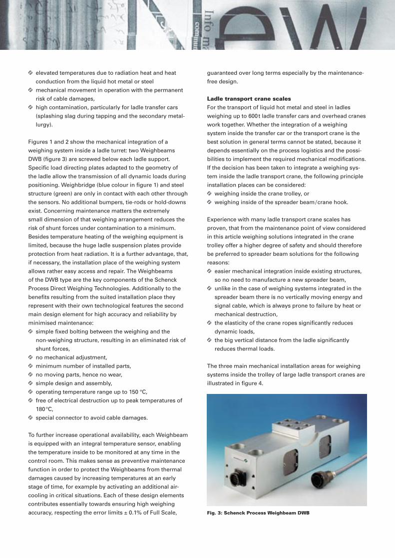
Figures 1 and 2 show the mechanical integration of a
weighing system inside a ladle turret: two Weighbeams
DWB (fi gure 3) are screwed below each ladle support.
Specifi c load directing plates adapted to the geometry of
the ladle allow the transmission of all dynamic loads during
positioning. Weighbridge (blue colour in fi gure 1) and steel
structure (green) are only in contact with each other through
the sensors. No additional bumpers, tie-rods or hold-downs
exist. Concerning maintenance matters the extremely
small dimension of that weighing arrangement reduces the
risk of shunt forces under con tamin a tion to a minimum.
Besides temperature heating of the weighing equipment is
limited, because the huge ladle suspension plates provide
protection from heat radiation. It is a further advantage, that,
if necessary, the installation place of the weighing system
allows rather easy access and repair. The Weighbeams
of the DWB type are the key components of the Schenck
Process Direct Weighing Technologies. Additionally to the
benefi ts resulting from the suited installation place they
represent with their own technological features the second
main design element for high accuracy and reliability by
minimised maintenance:
simple fi xed bolting between the weighing and the
non-weighing structure, resulting in an eliminated risk of
shunt forces,
no mechanical adjustment,
minimum number of installed parts,
no moving parts, hence no wear,
simple design and assembly,
operating temperature range up to 150 °C,
free of electrical destruction up to peak temperatures of
180 °C,
special connector to avoid cable damages.
To further increase operational availability, each Weighbeam
is equipped with an integral temperature sensor, en abling
the temperature inside to be monitored at any time in the
control room. This makes sense as preventive maintenance
function in order to protect the Weighbeams from thermal
damages caused by increasing temperatures at an early
stage of time, for example by activating an additional air-
cooling in critical situations. Each of these design elements
contributes essentially towards ensuring high weighing
accuracy, respecting the error limits ± 0.1% of Full Scale,
guaranteed over long terms especially by the maintenance-
free design.
Ladle transport crane scalesFor the transport of liquid hot metal and steel in ladles
weighing up to 600 t ladle transfer cars and overhead cranes
work together. Whether the integration of a weighing
system inside the transfer car or the transport crane is the
best solution in general terms cannot be stated, because it
depends essentially on the process logistics and the possi-
bilities to implement the required mechanical modifi cations.
If the decision has been taken to integrate a weighing sys-
tem inside the ladle transport crane, the following principle
installation places can be considered:
weighing inside the crane trolley, or
weighing inside of the spreader beam / crane hook.
Experience with many ladle transport crane scales has
proven, that from the maintenance point of view considered
in this article weighing solutions integrated in the crane
trolley offer a higher degree of safety and should therefore
be preferred to spreader beam solutions for the following
reasons:
easier mechanical integration inside existing structures,
so no need to manufacture a new spreader beam,
unlike in the case of weighing systems integrated in the
spreader beam there is no vertically moving energy and
signal cable, which is always prone to failure by heat or
mechanical destruction,
the elasticity of the crane ropes signifi cantly reduces
dynamic loads,
the big vertical distance from the ladle signifi cantly
reduces thermal loads.
The three main mechanical installation areas for weighing
systems inside the trolley of large ladle transport cranes are
illustrated in fi gure 4.
Fig. 3: Schenck Process Weighbeam DWB

press–press–press–press–press press–press–press–press–press
As the available headroom for existing cranes usually
rules out the option of weighing the entire crane trolley by
means of a double frame, only the solutions 2) and 3) will be
outlined below.
Example 2: Weighing of the crane trolley in the area of the wheelbaseThe design principle of this solution consists of the integra-
tion of several weighing units at the mechanical interface
between trolley frame and wheelbase, in order to measure
the total weight of the ladle transmitted over this section. It is
self-evident, that this solution has to be capable to transmit
all horizontal and vertical forces applied during normal crane
operation. Each weighing unit consists internally of several
Weighbeams DWB as presented before. The low required
headroom of 220 mm, visible in fi gures 5 and 6, makes the
solution extremely suitable for revamping existing crane
trolleys. On the other hand, seen the huge vertical space and
the investment for a heavy double weighing frame, its not
surprising, that the wheelbase design is more and more also
selected for new ladle transport crane weighing systems.
The main advantages of the wheelbase weighing concept in
terms of accuracy, reliability and ease of maintenance are:
maintenance-free installation through completely bolted
weighing units,
the existing mechanical connections / screw fi xations of
the crane structure are used with out any modifi cation for
the fi xation of the weighing units,
no moving parts, no adjustment or wear,
no critical cable connections,
the weighing system can easily be protected from heat
radiation due to its compact and modular design.
Ladle transport crane scales designed according to this
principle usually respect error limits ± 0.1 % of Full Scale.
Example 3: Weighing at the crane trolley inside the upper sheave block The variety of crane executions forces designers of weigh-
ing equipment to keep an open eye for several possible
variants at all times, fi nally fi nding a suitable solution
concerning accuracy, costs of equipment and installation,
downtime necessary for the weighing modifi cation,
installation height and maintenance properties. During the
design of weighing systems for those heavy ladle trans-
port cranes especially the required time for modifi cation
and maintenance has to be taken into account, as these
cranes usually operate around the clock and minimum
maintenance shifts will leave virtually no time for works
on weighing equipment for months. The second applica-
tion example for a crane weighing systems often is suited
in cases, where weighing equipment at the wheelbase
cannot be realised for reasons of mechanical adaptation.
Figures 7 and 8 show as alternative solution a very simple
weighing installation inside the main hoist upper sheave
block supporting plates.
The approach used for this weighing system is based on
force sensors developed specifi cally for this application, the
so-called Radial Force Sensor DRA (fi gure 9), installed inside
the vertical supporting plates of the upper sheave blocks.
These sensors measure and transmit radial loads applied
by the crane cables, in this execution directly converting
the supporting plates to a part of the weighing system
according to the Direct Weighing Technology principle. Main
features and design advantages of this solution are:
no modifi cation of the crane static’s,
no modifi cation of the main axle diameter and the
sheaves used by the customer,
no additional headroom,
Fig. 4: Installation places for a weighing system inside the trolley of a ladle transport crane 1) total weighing of the crane trolley with a double frame, 2) total weighing of the trolley in the area of the wheelbase, 3) partial weighing of the upper sheave block.
1
2
3
Fig. 5: Basic structure of weighing in the area of the wheelbase (Courtesy: Arcelor Gent (SIDMAR))
trolley frame
wheelbase
wheighing unit

extremely easy and fast retrofi t: pre-assembly of the
DRA sensors inside a new sheave block in the workshop,
followed by welding this block onto the crane trolley steel
frame.
With a view to the positive maintenance properties, this
solution is essentially equivalent to weighing equipment
installed in the area of the wheelbase particularly concern-
ing the uncritical cable ways. Considering access to the
mechanical structure and temperature protection, it has
to be judged even superior. Upper sheave block weighing
systems measure up to 90 % of the ladle weight through the
crane cable forces. To compensate the height depending ef-
fects of the non-weight cables to the cable drum, advanced
weighing electronics provide a cable length compensation,
enabling those scales to respect the error limits ± 0.2 % of
Full Scale.
Example 4: Scrap yard scalesNext to the steel works, scrap yards are another major
application area with specifi c demands on in-process
weighing equipment. Although thermal loading does not
play a particularly important role in this part of the plant,
high mechanical loads occur during charging of scrap for
the converter or the EAF: frequently, the impact of a single
block of scrap with a weight of 5t dropping from a height
of 5 m inside the unloaded basket must pass the weighing
system safely. Other important conditions for weighing
systems used for scrap charging are:
during cleaning the weighing platform from scrap
residues with the electromagnet, strong lift-off forces are
applied on steel weighbridges,
undamped dropping of scrap pieces will frequently also
cause additional horizontal loads.
In the past, scrap weighing systems frequently were
designed as raising platform scales, taking into account
these diffi cult operational conditions: during dynamic load-
ing the Loadcells were taken out of operation and therefore
protected from excessive loads. Only at the expected end of
the loading process a hydraulic system directed the weight
over the Loadcells to the ground, so that the scrap mass
charged up to this moment could be displayed. This solu-
tion contained the following fundamental disadvantages:
no information about the weight already loaded during
the charging process,
diffi cult procedure to arrive at the desired set point,
the entire hydraulic and control system requires signifi -
cant maintenance,
during normal production the mechanics and hydraulics
in the concrete foundation are not accessible for control
and maintenance,
loss of time.
As this example shows, scrap yards require special weigh-
ing solutions ensuring highly accurate and low maintenance
operation. Technical progress achieved over the last years
cane trolley frame
wheighing unit
wheelbase
Fig. 6: Weighing unit of a 400 t ladle transport crane (Courtesy: Siemens VAI)
sheaves and axle
supporting plates DRA sensor
Fig. 7: Basic structure of an upper sheave block weighing system

press–press–press–press–press press–press–press–press–press
has provided such solutions. Basically, four possible installa-
tion places can be distinguished for weighing systems used
on the scrap yard, depending on the underlying logistical
concept:
stationary on-fl oor mounted platform scales installed in
a roofed scrap building, on which scrap buckets are posi-
tioned with the help of the huge scrap transport crane,
stationary in-pit platform scales for outdoor installation,
on which scrap buckets, chutes, trailers or wagons are
positioned for charging and weighing,
mobile scales integrated inside scrap transfer cars, trail-
ers or carrier racks, and
crane scales integrated inside the small scrap charging
cranes.
Each of these places has its own advantages and incon-
venients, so that the best weighing solution can only be
determined by carefully analysing the exact conditions at
site. Essential criteria with regard to design, maintenance
and accuracy are:
Platform scale in the scrap hall:
best solution, but requiring heavy investment.
Outdoor platform scale:
risk of weighing errors and high maintenance effort due to
blocking of the platform gap with small scrap parts and high
contamination of the foundation pit by dirt.
Mobile weighing systems:
reduced risk of shunt forces due to the installation place
of the weighing components above fl oor, but need of ad-
ditional elements for power supply and data transmission.
Besides additional headroom is needed.
Loading crane scales:
normally diffi cult to retrofi t due to the cost and time effort
connected with the modifi cation. Signifi cant weighing errors
arise from the fact, that parts of the scrap weighed while
hanging on the crane do not drop into the basket.
The following example shows a solution, that has been found
to work properly both as in-pit platform and mobile scale:
Figures 10 and 11 show a simple design for a heavy scrap
weighbridge 5 x 5 m based on Schenck Process Weigh-
beams. Also in this case the weighbridge is completely
screwed onto the Weighbeams, ensuring that the weight
of the scrap is accurately determined and displayed at
all times of the loading process. Hydraulic equipment no
longer is required and the simple execution without any
tie-rods means, that the mechanical equipment works
maintenance-free. The overall concept of this special
platform scale includes the following additional elements
to optimise the availability:
high overload capability up to several times the Weigh-
beam nominal capacity, ensuring that the system will
transmit even extreme impact loads without suffering
damages,
high permissible horizontal defl ection of the weighbridge,
resulting in a self cleaning effect of the weighbridge gap
during operation.
As this example demonstrates, Direct Weighing Technolo-
gies allow integral weighing solutions, that provide the
design features customers expect from advanced scrap yard
weighing systems:
total error limits ± 0.1 % of Full Scale,
charging accuracy for scrap up to ±1 % of the net
mass,
uncritical transmission of impacts into the foundation,
minimum inspection and maintenance requirements.
This last example completes the presentation of some
mechanical weighing solutions conceived specifi cally for
in-process weighing systems of steel industry. All solu-
tions, consisting of sensors and surrounding mechanical
arrangements, have been developed through longstand-
ing, close cooperation between Schenck Process and its
partners in steel industry. Various other applications have
been optimised concerning the weighing performances
in a similar manor using Direct Weighing Technologies:
examples are torpedo railway scales or top hopper scales
of Blast Furnaces.
Fig. 8: New upper sheave block 350 t with pre-assembled DRA-sensors (Courtesy: Ternium Sidor), Fig. 9: Schenck Process Radial Force Sensor DRA
Fig. 10: Basic structure of a platform scale for scrap loading
As a comparison:conventional solutions for industrial weighing systems requiring legal-for-trade certifi cation The huge variety of weighing applications in steel plants
has to be distinguished in legal-for-trade and in-process
systems: legal-for-trade scales usually are located at the
beginning of the production process for the purchase of
raw materials and end for the sale of coils, bundles or
fi nished sections. In these areas the ambient conditions
for the installation of weighing systems do not pose major
problems for the so-called conventional weighing solutions.
They are designed as hopper scales, road weighbridges and
crane or roller table scales with a weighing range between
1 and 100 t. The weight is transmitted through a bridge
structure and several legal-for-trade approved Loadcells
with appropriate mounting elements (fi gure 12 and 13) to
the ground. The installation example in fi gure 14 shows
a typical coil scale with a weighing range of 35 t and a
legal-for-trade increment of 10 kg, executed with 4 Loadcells
RTN 33 t C5. This conventional solution for the weighing
mechanics, based on Loadcells, Elastomer Mounts and
external bumpers has proven to work extremely reliable in
steel plants worldwide. It is cost-effi cient, very accurate and
requires only a minimum of maintenance. As all legal-for-
trade scales need periodic re-certifi cation at any rate, this
will ensure that the operating status of the weighing system
is routinely checked at regular intervals.
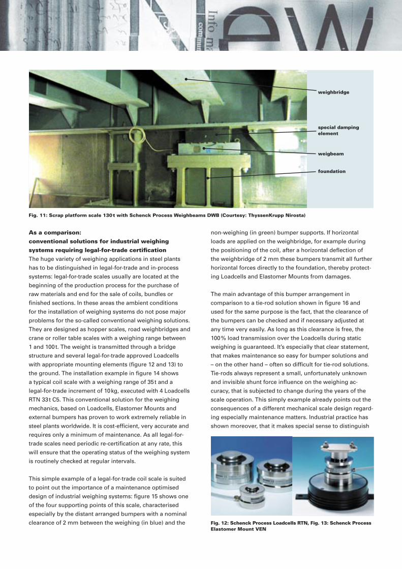
This simple example of a legal-for-trade coil scale is suited
to point out the importance of a maintenance optimised
design of industrial weighing systems: fi gure 15 shows one
of the four supporting points of this scale, characterised
especially by the distant arranged bumpers with a nominal
clearance of 2 mm between the weighing (in blue) and the
non-weighing (in green) bumper supports. If horizontal
loads are applied on the weighbridge, for example during
the positioning of the coil, after a horizontal defl ection of
the weighbridge of 2 mm these bumpers transmit all further
horizontal forces directly to the foundation, thereby protect-
ing Loadcells and Elastomer Mounts from damages.
The main advantage of this bumper arrangement in
comparison to a tie-rod solution shown in fi gure 16 and
used for the same purpose is the fact, that the clearance of
the bumpers can be checked and if necessary adjusted at
any time very easily. As long as this clearance is free, the
100 % load transmission over the Loadcells during static
weighing is guaranteed. It’s especially that clear statement,
that makes maintenance so easy for bumper solutions and
– on the other hand – often so diffi cult for tie-rod solutions.
Tie-rods always represent a small, unfortunately unknown
and invisible shunt force infl uence on the weighing ac-
curacy, that is subjected to change during the years of the
scale operation. This simply example already points out the
consequences of a different mechanical scale design regard-
ing especially maintenance matters. Industrial practice has
shown moreover, that it makes special sense to distinguish
weighbridge
special damping element
weigbeam
foundation
Fig. 11: Scrap platform scale 130 t with Schenck Process Weighbeams DWB (Courtesy: ThyssenKrupp Nirosta)
Fig. 12: Schenck Process Loadcells RTN, Fig. 13: Schenck Process Elastomer Mount VEN
press–press–press–press–press press–press–press–press–press
the in-process weighing systems from the legal-for-trade
systems presented above concerning maintenance matters.
A principal argument for this approach is the fact, that
in-process weighing systems have to work under entirely
different operational conditions, as listed in the previous
chapters.
The next chapter describes a number of features of
advanced weighing electronics, that also contribute es-
sentially towards increasing the functional reliability and
availability of weighing systems and that enable preventive
maintenance.
Last but not least: features of modern weighing electronicsAdditionally to the modern mechanical solutions today’s
weighing electronics also contribute to increase operational
reliability and reduce maintenance of in-process scales.
The primary task of the weighing electronics is to fi lter and
convert the analogue signals in the range of only a few Mil-
livolts from the sensors to a stable digital signal. Due to the
specifi c ambient conditions for in-process scales the Direct
Weighing Loadcells still today are designed as analogue
and not as digital Loadcells. Nevertheless the advantages of
digitalisation are available inside Schenck Process scales as
well.
As a fi rst example for advanced weighing electronics fi gure
17 shows the DISOBOX®. Installed in a fi eld housing it is
designed for an installation close to the weighing mechan-
ics. Inside the DISOBOX® every single Loadcell input signal
is digitized and transformed into weight values by up to 8
independent A/D converters. The total weight is calculated
based on these individual weights by simple software addi-
tion. The output cable transmits the single weights and the
total weight directly to the customer control system by serial
interface. The major advantage of this weighing electronics
is the fact, that the weight measured by every single Load-
cell is available in the control room at any time. This enables
maintenance staff to detect assumed sensor performance
deterioration, for example caused by cable damages, and
to switch off this Loadcell electronically without costly and
time-consuming intervention outside in the fi eld, until repair
or exchange is possible. Over and above this possibility of a
manual intervention, the DISOBOX® also features automatic
monitoring functions such as continuous zero signal check-
ing, allowing to recognise automatically gradual growing
errors for example caused by increasing shunt forces at
a very early stage of time. By an automatically generated
warning in case of discrepancies that self-check of every
single Loadcell increases the operational reliability and
accuracy of the weighing system signifi cantly. Also, early
recognition of potential future problems reduces the total
maintenance effort and the risk of sudden failures with the
associated serious impacts on production and control.
Different to the DISOBOX® the DISOMAT® B plus (fi gure 18)
has been designed as a Weighing Terminal for applications
with data exchanges by a scale operator for example
in a crane cabin, requiring display and push buttons.
Considering specifi cally maintenance aspect, fi rst the
integrated load totalising memory module enables the crane
maintenance staff to receive an accurate report about the
Fig. 17: Schenck Process DISOBOX®
, Fig. 18: Schenck Process DISOMAT
®
B plus
Fig. 14: Basic structure of a legal-for-trade coil scale 35 t
coil sizes
weighbridge
foundation
external bumper
loadcell with elastomer mount
tie-rod
bumper clearance 2 mm
non-weighing bumper support
weighing bumper support
Fig. 15: Bumpers for horizontal load transmission, Fig. 16: Tie-rods for horizontal load transmission

total mechanical load cycles applied on the crane mechanics
over a defi ned period of time, allowing optimally expanded
maintenance intervals depending on the varying loading
conditions. A second major contribution in terms of ease
of maintenance is made available by the DISOMAT® B plus
advanced communication capabilities, for example through
the Ethernet interface. In Web Server operation all essential
data of the weighing system can be displayed by means of
an Internet Browser, simply by selecting the associated IP
address. Given the appropriate authorisation weighing data
can be viewed throughout a company‘s Intranet or even
from outside through the Internet. This will provide to the
maintenance workshop in charge of the weighing systems
quick and easy information concerning the proper function
of the most important in-process scales. Figure 19 visualises
as typical in-process weighing application a modern ladle
transfer car electronics. The combination of the DISOBOX®
located in the fi eld and the DISOMAT® B plus installed in the
control room represents the maximum degree of preventive
maintenance optimisation due to the following features:
single sensor weight monitoring in the control room,
emergency mode operation and calibration from the
control room,
wireless data transmission between the fi eld and the
control room, hence no endangered cable connection,
safe digital data transmission.
Figure 19. Application example for a ladle transfer car weighing electronics
BV
-S 2
025
GB
10
00.0
2.07
di ·
All
info
rmat
ion
is g
iven
wit
ho
ut
ob
ligat
ion
.
All
spec
ifica
tio
ns
are
sub
ject
to
ch
ang
e.
Schenck Process GmbHMarketing CommunicationPallaswiesenstr. 10064293 Darmstadt, GermanyT +49 61 51-32 29 87F +49 61 51-32 27 [email protected]
ConclusionAt the end of the presentation of some advanced solutions
for in-process weighing systems we hope having been able
to demonstrate, that especially for these kind of scales a
higher effort in the mechanical and the electrical design
in order to achieve largely accurate, reliable and highly
maintenance-reduced weighing systems is more than justi-
fied by the increase of confidence in the scale performances,
leading for the instrumentation or maintenance department to
a minimisation of maintenance and control time effort,
an expansion of maintenance and control intervals, and
minimised trouble-shooting and analyse actions.
The production department also benefits from those highly
maintenance-reduced scales by an increased accuracy,
reliability and availability of the scales for their original
purposes in the process control. Confidence in weighing
systems means, that the correct operation condition is
confirmed by a proper and mechanically stable design over
long times of operation, leading to minimised time and ma-
terial effort for checking and re-calibration. Schenck Process
in-process scales usually are only checked in time intervals
of 3-6 month in the following simple manor:
visual control of the surrounding of the scale mechanics,
control of an eventual change of the offset signal stored
inside the weighing electronics,
one check-weighing with a test weight as confirmation of
the still correct calibration.
A further benefit of maintenance-free scales is the reduced
need for spare parts, as Direct Weighing solutions are not
subjected to any mechanical movement or wear and with-
stand the normal harsh environmental conditions without
any aging.
Especially the close cooperation between steel plant
operators, plant designers and weighing specialists has
ensured a continuous technological progress for in-process
weighing systems within the last years. As system supplier
we guarantee for the specified accuracy of the entire weigh-
ing system in operation, proven by the optimally suited
mechanical and electrical components and our engineering
as base for long year proper weighing operation regarding
accuracy, reliability and maintenance effort. In-house
development, design and production of Direct Weighing
Technologies for steel industry enables Schenck Process to
meet ever growing customer requirements, assuring to all
partners involved a continuous benefit also in future.
Author:
Martin Brauer, Manager Static Weighing Technology,
Schenck Process GmbH, Darmstadt, Germany

05.07.450. We reserve the right to discontinue or change specifications Heavy Industry 18.2007
Weighing systems for long products: It’s the detail that makes the difference! The photo at this page shows a typical cooling bed at the end of the continuous casting machine for billets of up to 6 t weight and total length of up to 15 m. Additional to the fixed and the moving fence, that execute the billet trans-port and revolving the photo shows in one special position some other supporting fingers for the billets: they repre-sent the upper part of a billet weighing system integrated inside the cooling bed. Weighing systems at this position contribute significantly to an optimised productivity and efficiency of steel produc-tion, because the weight controlled operation of the torch allows to cut billets with a precisely determined weight even under the wear of the casting mould (leading to lar-ger cross sections) or density variations. Consequently the following rolling mill produces from these billets wire rod with exactly desired diameter and length, leading only to minimised waste, that has to be re-molten. Further applications of long product scales are the entry of the rolling mill or its exit, for example for sampling a desired number of bars to bundles.
The following operating conditions pose high require- ments to the installed weighing equipment: - weighbridges with a length up to 15 m - huge structural height - light execution of the weighbridge steel structure
- little weighing range of maximum 10 t - possible enhanced dynamic loads - high product temperature of 400 °C and more - strong heat radiation and temperature gradients - desired accuracy up to ± 0,1 % of Full Scale, sometimes legal-for-trade requirements - difficult access for installation and maintenance in terms of time and space. On the following page we like to present the main ele-ments of the Schenck Process solution, that guarantee best weighing results for this special weighing application:

Decisive for a high weighing accuracy is the choice of perfectly suited weighing components. Especially the huge elastic temperature expansion of the weighbridges represent the main task, easily to explain by the following example: A weighbridge with a total length of 15 m is subject to a thermal expansion of 18 mm under a temperature change of only 100 °C. This unavoidable expansion not only charges all fixation elements. Moreover as the foundation usually is hardly heated up it has to be compensated by the weighing components, that are exactly arranged at the interface between the warmer and the colder areas of the total installation.
BV
-A10
26G
B X
BS
05.
07.4
50. W
e re
serv
e th
e rig
ht to
dis
cont
inue
or c
hang
e sp
ecifi
catio
ns a
t any
tim
e w
ithou
t not
ice
or o
blig
atio
n.
Schenck Process usually chooses the so-called Double Elastomer Mount as shown at the following drawing to fulfil with this special weighing task:
This Double Elastomer mount first of all consists of two standard elastomers VEN, that transmit and measure all vertical forces of deadload and product weight together with the Loadcell RTN in between to the ground. Designed with an expanded temperature range up to 110 °C and a relatively high nominal capacity this weighing unit is ex-tremely elastic, shock adsorbing and insensitive against all kinds of installation tolerances. Nevertheless the most important feature is its ability to allow horizontal deflec-tions of the weighbridge due to thermal expansion in rela-tion to the ground foundation of up to 12 mm per loading point without negative effects on the weighing accuracy. The photo on the right side shows such a loading point during installation under the weighbridge in a cooling bed: easy to recognise are the two black elastomers, sur-rounded by an external water-flown cooling unit. Above the upper elastomer additional heat isolation plates can be found, assisting to reduce the vertical heat flow in opera-
tion. Finally, the photo shows the connection of the weigh-ing unit to the upper weighbridge and the lower steel foundation. Good experience has been achieved also by using at that stage of the works the shown dummy-Loadcells, replaced by the original sensors at the very end of all installation, welding and adjustment works: a further contribution for an improved assembly security and Loadcell protection. Further details of our total weighing solution for long prod-uct scales (not shown at the photo above) are suited de-signed bumpers for the transmission of horizontal over-loads and hold-downs, that remain free of shunt forces in all stages of operation. Besides, we install as weighing electronics (like in more and more steel production scales) our A/D-converter DISOBOX, that at the same time dis-plays and transmits the total billet weight to the production and additionally the loading per single loadcell as special preventive maintenance feature.
Double Elastomer
The weighing application „Long product scale” with its high accuracy requirements in the range of a few kg con-firms convincingly, that only an optimally adapted choice of the weighing elements guarantees high availability and accuracy in all stages of cold and hot operation. In contra-diction weighing accuracy data determined under labora-tory conditions and presented in general component data sheets have no practical meaning! For these reasons our statement remains valid: Check Your application with the specialists of Schenck Process, because our worldwide experience is Your benefit!
Schenck Process GmbH Pallaswiesenstr. 100 64293 Darmstadt, Germany T +49 6151 32-3625 F +49 6151 32-3270 [email protected]

Modernisation of weighing systems in spreader beams - state-of-the-art technology with minimal investment!
Ladle and coil transport cranes are the steel plants most
important logistic devices for safe and reliable material
transport.
Integrated weighing systems in cranes moreover allow
better than any other weighing system the establishment
of material balances: starting from the empty ladle tare
weight over the crude steel and alloy weighing to the
pass-over of the finished steel to the continuous casting
machine and finally the rest steel determination after the
casting end. For this reason the big engineering compa-
nies often installed weighing systems in spreader beams
during the erection period of many steel mills in the 70th
and 80th of the last century.
Today frequently these older scales are not in operation
anymore or do not represent state of the art equipment for
the following reasons:
- high weighing errors or even scale
destruction by mechanical overloads
applied on Loadcells or mounts
over the years of operation,
- damages of the weighing mechanics
by high operation temperature,
- expiring spare part availability,
- missing features of modern data
communication.
Based on the fact, that it represents an ex-
tremely high effort to integrate a completely
new weighing system inside given me-
chanical structures of such huge cranes it is
obvious, that the utilisation of the existing
weighing space contains high potential for
an economical and quick modernisation of
both the
- weighing mechanics and the
- electronic data processing.
At the following two pages we like to present some impor-
tant elements of such a weighing modernisation of
spreader beam scales.
08.07.450. We reserve the right to discontinue or change specifications
Heavy Industry 19.2007

First of all we check the actually installed weighing me-
chanics by analysing the installation drawings of the
weighing supports (see attached example below) and
- sometimes even more important - the operators experi-
ence with the old scale.
This analyse leads to the design of several geometrical
adaptations for the new weighing supports based on new
Loadcells.
Focus of this design process is the intention to replace the
old system by the new one without any mechanical works
on the crane by simple exchange, using the existing fixa-
tion interfaces again.
The drawing below shows the result of that engineering
for the above shown old weighing support.
The choice of the very robust and compact Schenck
Process Loadcells RTN usually allows to use the given
installation volume offered by the old scale without need
of additional headroom or new fixation interfaces. This
leads to very simple solutions installed in extremely short
shut down-times of the spreader beams.
During the engineering we also check the mechanical load
transmission between the spreader sheave blocks and the
main beam structure in all other non-weighing directions in
order to guarantee, that the weighing modernisation main-
tains all force transmission ways, so that the initial calcula-
tion of the crane statics according to DIN 15018 remains
valid unchanged.
A weighing modernisation performed following these prin-
ciples only needs the following elements:
- standard Schenck Loadcells of the RTN family,
- a set of tailor-made adaptation plates,
- mechanical engineering for the calculation and the
design of the new weighing supports.
The advantages of this easy revamping are convincing:
- Schenck accuracy guarantee up to an error limit of
± 0,1 % of Full Scale,
- service temperature up to 110° C (optional),
- maintenance-friendly solution with proven Loadcells
for the harsh steel plant environment,
- security concerning the spare part supply for the next
years of operation.
The following photo shows the installed weighing
support of the modernisation example on the left side:

BV
-A102
7G
B X
BS
08.0
7.4
50. W
e r
ese
rve t
he
rig
ht to
dis
co
ntin
ue o
r ch
ang
e s
pecific
atio
ns a
t any t
ime w
itho
ut n
otice
or
oblig
ation.
In completion of such a successful mechanical revam-
ping we recommend to take the chance for an electrical
modernisation as well in order to use the various features
of modern weighing electronics in terms of safe crane
operation and maintenance assistance.
The diagram at this side shows as example the general
configuration of a modernised crane weighing electronics,
which we have realised in cooperation with our represen-
tative SCHILTZ Graviconcept in Belgium.
It starts with the Loadcells on the spreader beam and
ends with the transmission of the weighing data to the
costumers PLC at the ground:
The key element of this solution is the Weighing
Terminal DISOMAT Bplus (that is followed since July
2007 by the new DISOMAT Tersus!) with the following
characteristics:
- collective load memory monitoring the crane
charging history as input for optimised maintenance
intervals of the entire crane mechanics,
- 2 separated measuring circuits enabling the detection
of wrong hook engagement or eccentric suspended
charges,
- radio transmission of the ladle weight and the casting
speed (t/h) to different locations, simplifying cabling
works between the crane and the ground,
- quick digital output contacts used for overload
detection,
- modern field bus interface Profibus DP for the
communication with the level two PLC.
Additionally to this executed reference the following func-
tions of Schenck weighing electronics are available for a
further improved crane and weighing operation:
- continuous supervision of all single Loadcell signals
for preventive maintenance by the installation of a
DISOBOX on the spreader beam,
- safe serial transmission of the weighing and process,
data between the spreader beam and the crane cabin,
- simple integration of locally existing interfaces like
hand control panels by adjustable functional block
configuration of the DISOMAT,
- Ethernet interface including remote access.
Existing devices, that have proven to work
reliably in the harsh steel pant environment
(as cable drums or Schenck supplied large
displays) can be easily integrated in the total
weighing arrangement.
This overview confirms, that not always huge investment
is needed to improve the profitability of the steel making
process significantly.
Specialised on crane scales for long years Schenck Proc-
ess is prepared to work out tailor made modernisation kits
for Your spreader beam weighing systems. With regard to
the significance of reliable crane scales for steel produc-
tion control, any investment will pay off in extremely short
time.
To summarise: better stop complaining about prob-
lems of old crane scales and start to modernise them
with us!
Schenck Process GmbH Pallaswiesenstr. 100 64293 Darmstadt, Germany T +49 6151 32-3625 F +49 6151 32-3270 [email protected]