realization of policy-based resource management … of policy-based resource management concept, ......
TRANSCRIPT

1/39 Future Internet Program
Realization of Policy-Based Resource Management Concept, Version 1.0 16.02.2010 FI DA2.2.20
Realization of Policy-Based Resource Management Concept
Future Internet Program of TIVIT,
Activity 2.2 Deliverable 2.2.20
Contributors:
Janne Tervonen, NSN Jari Mustajärvi, NSN

2/39 Future Internet Program
Realization of Policy-Based Resource Management Concept, Version 1.0 16.02.2010 FI DA2.2.20
Table of contents
Abbreviations and Terminology....................................................................... 3
1. Introduction....................................................................................... 4
2. PBRM Realization............................................................................. 5
2.1 Access Network Discovery and Selection Function ........................................................5 2.1.1 Overview ........................................................................................................................5 2.1.2 ANDSF Features ............................................................................................................6 2.1.3 Standardization Status....................................................................................................8 2.1.4 Realization of PBRM with ANDSF ..................................................................................8 2.2 Media Independent Handover Services ..........................................................................9 2.2.1 Overview ........................................................................................................................9 2.2.2 MIH Features................................................................................................................10 2.2.3 Standardization Status..................................................................................................12 2.2.4 Realization of PBRM with MIH......................................................................................12 2.3 Summary......................................................................................................................13
3. PBRM Server Interworking with Other Network Elements............... 15
3.1 Security Framework......................................................................................................15 3.1.1 Generic Authentication Architecture for ANDSF ...........................................................15 3.1.1.1 Overview ......................................................................................................................15 3.1.1.2 GAA Architecture..........................................................................................................16 3.1.1.3 Using GAA with ANDSF ...............................................................................................17 3.1.2 MIH Security.................................................................................................................18 3.2 Subscriber Database ....................................................................................................19 3.2.1 Overview ......................................................................................................................19 3.2.2 User Data Convergence ...............................................................................................20 3.2.3 Using UDC with ANDSF ...............................................................................................21 3.3 Policy and Charging Control .........................................................................................22 3.3.1 Overview ......................................................................................................................22 3.3.2 IP Flow Mobility ............................................................................................................24 3.3.3 ANDSF Role.................................................................................................................24
4. PBRM Signaling Load..................................................................... 26
4.1 ANDSF Signaling..........................................................................................................26 4.1.1 OMA DM Framework....................................................................................................26 4.1.1.1 Data Model ...................................................................................................................26 4.1.1.2 OMA DM Information Exchange ...................................................................................27 4.1.1.3 An Example DM Management Session ........................................................................28 4.1.2 ANDSF Signaling Load.................................................................................................31 4.1.2.1 ANDSF Management Object ........................................................................................31 4.1.2.2 ANDSF Accessing Scenarios .......................................................................................33 4.2 MIH Signaling ...............................................................................................................35 4.2.1 MIIS Message Exchange..............................................................................................35 4.2.2 MIIS Signaling Load .....................................................................................................36 4.3 Summary......................................................................................................................36

3/39 Future Internet Program
Realization of Policy-Based Resource Management Concept, Version 1.0 16.02.2010 FI DA2.2.20
5. References ..................................................................................... 38
6. Acknowledgements......................................................................... 39
Abbreviations and Terminology 3GPP 3rd Generation Partnership Project AAA Authentication, Authorization & Accounting ACL Access Control List AKA Authentication and Key Agreement ANDSF Access network discovery and selection function BSF Bootstrap Server Functionality B-TID Bootstrapping Transaction Identifier (GAA) CS Circuit Switched DM Device Management DSMIPv6 Dual Stack Mobile IPv6 DVB Digital Video Broadcasting EPC Evolved packet core ePDG Evolved Packet Data Gateway EPS Evolved packet system E-UTRAN Evolved UMTS Terrestrial Radio Access Network (4G) FE Front End FQDN Fully Qualified Domain Name GAA Generic Authentication Architecture GSM Global System for Mobile communications HA Home Agent HSS Home Subscriber Server H-ANDSF Home network ANDSF HTTP Hypertext Transfer Protocol HTTPS Secure HTTP (using TLS) IEEE Institute of Electrical and Electronics Engineers IFOM IP Flow Mobility IMS IP Multimedia Subsystem IP Internet Protocol LAN Local Area Network LTE Long Term Evolution MBMS Mobile Broadcast Multicast Service MICS Media Independent Command Service MIES Media Independent Event Service MIH Media Independent Handover Services MIIS Media Independent Information Service MO Management Object NAF Network Application Functionality OMA Open Mobile Alliance PBRM Policy Based Resource Management PCC Policy Charging and Control PCEF Policy and Charging Enforcement Function PCRF Policy and Charging Rules Function PDN GW Packet Data Network Gateway

4/39 Future Internet Program
Realization of Policy-Based Resource Management Concept, Version 1.0 16.02.2010 FI DA2.2.20
PLMN Public Land Mobile Network PMIP Proxy Mobile IP PS Packet Switched PSK Pre-Shared Key QoS Quality of Service RAN Radio Access Network RAT Radio Access Technology S-GW Serving Gateway SPR Subscription Profile Repository SSID Service Set Identifier TLS Transport Layer Security TLV Type Length Value UDC User Data Convergence UDR User Data Repository UE User Equipment URI Uniform Resource Identifier V-ANDSF Visited network ANDSF WAP Wireless Application Protocol WBXML WAP Binary XML WCDMA Wideband Code Division Multiple Access WiMAX Worldwide Interoperability for Microwave Access WLAN Wireless LAN XML Extensible Markup Language
1. Introduction This document is deliverable DA2.2.20 for activity 2.2 Task 7 of Future Internet program of TIVIT. This document covers the continuation of work for Policy-Based Resource Management (PBRM) within Task 7 during 2H2009. Earlier work related to PBRM can be found from other Future Internet deliverables [1], [2], [3] and [4].
While previous work around PBRM has concentrated on the concept itself, this document takes a look how PBRM concept could be realized in live networks.
This document has two logically different parts: the first one – chapters 2 and 3 – covers the different realization options for PBRM concept and discusses with what network elements a PBRM server may need to interwork. The second part, i.e. chapter 4, discusses what kind of signaling load a real-life implementation of PBRM server could inflict in network. Each chapter is concluded separately.

5/39 Future Internet Program
Realization of Policy-Based Resource Management Concept, Version 1.0 16.02.2010 FI DA2.2.20
2. PBRM Realization As described in [1], the PBRM concept is built around client-server model, where UEs (i.e. terminals) assume the client role requesting network discovery and selection information from a PBRM server. In addition to that, the PRBM server preferably should also be able to push PBRM information to the UEs, e.g. when an urgent information update is needed.
In order to guarantee a working PBRM system, a well-defined interface is needed between the UEs and PBRM server: this can be achieved either by a standardized or a proprietary solution. While proprietary system would be possible to realize e.g. within an operator’s own network, the interoperability between other operators’ corresponding systems would be challenging to achieve. Thus, it is preferable to pursue a standardized PBRM solution to enable interworking system across network and operator boundaries.
Currently in standardization forums, there are two different active efforts to define PBRM-alike functionality: Access Network Discovery and Selection Function (ANDSF; refer to [5], [6] and [7] for more details) is being standardized within 3GPP and Media Independent Handover Services (MIH; refer to [8]) in IEEE. The scope of these two efforts is bit different: ANDSF is defined to be part of 3GPP next generation core network called Evolved Packet Core (EPC), while MIH is intentionally designed to be “media independent” and not tied to any specific network technology.
In order to realize the PBRM concept and to deploy it in a live network, a standardized solution is needed: currently, the best candidates for this are ANDSF and MIH standards. In this chapter, both standardization efforts are shortly described with their status updates. Also, the suitability of both candidates to realize PBRM concept is discussed.
2.1 Access Network Discovery and Selection Function
2.1.1 Overview
Traditionally, the cellular networks have been divided into two distinct parts: radio access network and core network. Radio access network is responsible to provide the radio coverage and connectivity for the UEs. Core network interconnects the cellular network to external networks, like the Internet, and also takes care of hosting subscribed database, AAA functions, billing, etc.
Together with the next generation radio access technology development – Long Term Evolution (LTE) – within 3GPP, also the core network has been under significant changes. The new core network architecture is called Evolved Packet Core (EPC). One of the main design principles of the EPC has been to allow the connection of basically any radio access technology (RAT) to EPC. For example, the same core network can be used for LTE and WLAN RATs, enabling also handovers between the different RATs. In the following figure, a simplified, general architecture for EPC is shown. The dotted lines represent signaling and solid lines user data interfaces. An explanation of the functions of the network elements can be found e.g. from [9] and [10].

6/39 Future Internet Program
Realization of Policy-Based Resource Management Concept, Version 1.0 16.02.2010 FI DA2.2.20
3GPP Access Trusted non-3GPP access
Untrusted non-3GPP access
S-GW
External IP networks
PDN GW ePDG
UE
ANDSFPCRF AAA
HSS
eNB
S14
Figure 1. Simplified EPC core network architecture.
In general, 3GPP classifies RATs to belong to either 3GPP (e.g. GSM, WCDMA, LTE) or non-3GPP (e.g. WLAN, WiMAX) technology families. In EPC, network selection and mobility is tightly controlled by the network for the 3GPP RATs. Due to terminal-centric mobility model e.g. in WLAN, the EPC and the operator cannot control what WLAN network the terminal selects. To help in this, a new, optional network element called Access Network Discovery and Selection Function (ANDSF) was introduced into EPC architecture.
2.1.2 ANDSF Features Currently within 3GPP standardization, non-3GPP RATs are seen as complementing technologies for 3GPP RATs. For example, one of the current standardization topics in 3GPP is to use WLAN as offloading technology for 3GPP cellular technologies: instead of putting all the possible traffic going through the operator 3GPP cellular radio and core networks, some part of the traffic – e.g. Internet browsing, video download, etc. – could be routed via non-3GPP radio networks directly to the Internet, bypassing operator cellular core network. This is where ANDSF could help: ANDSF can be used to deliver UEs instructions when and for what traffic to use e.g. WLAN instead of 3GPP networks.
In short, ANDSF is an operator tool to facilitate the subscribers’ network selection and inter-system mobility between 3GPP and non-3GPP networks or within non-3GPP networks to access services provided by the operator or services located in the Internet.

7/39 Future Internet Program
Realization of Policy-Based Resource Management Concept, Version 1.0 16.02.2010 FI DA2.2.20
ANDSF can also provide assistance for network discovery e.g. to spot legitimate access points in the proximity of the UE. ANDSF is being specified in 3GPP specifications 23.402 [5], 24.302 [6] and 24.312 [7].
ANDSF architecture is shown in Figure 2. The S14 interface between the UE and ANDSF server is defined to be based on Open Mobile Alliance (OMA) Device Management (DM) framework (look for chapter 4.1.1 for more details). OMA DM messages are transferred on top of IP, i.e. in order to contact ANDSF server, the UE needs an active user data connection to the network. As illustrated in the figure, ANDSF supports both non-roaming and roaming scenarios, i.e. the ANDSF services are accessible also when a subscriber is roaming in a visited network. ANDSF supports both push and pull model.
S14
S14 H-ANDSF
UE V-ANDSF
3GPP IP Access or Trusted/Untrusted
Non-3GPP IP Access
VPLMN
HPLMN
Figure 2. ANDSF architecture for roaming scenario [5].
ANDSF can provide both network selection policies and network discovery information (the term used in ANDSF are “Inter-system mobility policy” and “Access network discovery information”). ANDSF does not participate in active network selection procedure itself, it just provide guidelines for the UE to consider in network selections, e.g. when to perform a handover between different networks. UE should update ANDSF information for example when it enters to a roaming partner network or current information becomes obsolete.
The network selection of the UE is controlled via network selection policies. On the contrary to a traditional cellular network handover control, ANDSF influences the network selection decision only via previously assigned network selection policies, not via real time information exchange.
Network discovery information can be used to optimize UE’s scan operations: ANDSF server can e.g. indicate the areas (based either on geographical coordinates or some existing network reference, e.g. 3G network cell area, location area, etc.) where certain network should be possible to find, and UE can limit the scanning only within that area. The main benefit of this is saved battery life for the UE.

8/39 Future Internet Program
Realization of Policy-Based Resource Management Concept, Version 1.0 16.02.2010 FI DA2.2.20
In 3GPP, one important restriction to ANDSF has been defined: ANDSF can not affect existing PLMN selection rules and the use of 3GPP radio access technologies. Instead, the existing 3GPP mechanisms are used to choose 3GPP access network and to do handovers between them. In practice, this means ANDSF is mainly used for guiding the UEs between 3GPP and non-3GPP technologies. Currently, by far the most deployed non-3GPP radio technology is WLAN: thus, the main use scenario for ANDSF is to provide an operator a tool to influence the UEs’ WLAN usage.
2.1.3 Standardization Status In 3GPP, ANDSF was introduced in Release 8 that was planned to be completed by the end of year 2008. However, like the whole Release 8, also ANDSF was delayed and some fixing has been done throughout the year 2009. Now, the Release 8 version of ANDSF seems to be pretty stable. Release 8 ANDSF provides the basic functionality: for example, the roaming scenario depicted in Figure 2 is not included. It is unlikely that any UE or network equipment manufacturer will implement the partial ANDSF Release 8 solution.
The main addition the Release 9 ANDSF introduces is the missing roaming support. The Release 9 ANDSF standardization will not meet its intended schedule December 2009, but the Release 9 ANDSF should be finished during the first half of 2010. While writing this document, some issues related to the roaming support are still open and the details have not yet been fixed.
Currently, ANDSF specifications include definitions for UE – ANDSF server interworking and also specification for ANDSF security architecture. However, no interfaces between ANDSF server and other EPC core network elements are considered in 3GPP specifications to keep ANDSF framework simple.
When finalized, the Release 9 ANDSF will be the first really implementable version. Typically, it takes two to five years before a new standardized feature is implemented in products. Some operators have shown increasing interest towards the ANDSF to be used e.g. in traffic offloading to WLAN, so it is possible that the first ANDSF implementations will hit the markets within a few years, assuming also the UE vendors will support it.
2.1.4 Realization of PBRM with ANDSF
As described in [1], PBRM concept provides policy-based tool for the operators to influence how the subscribers use the operator various networks. The basic PBRM functionality – with network selection policy and selection information provisioning – can be achieved with a simple server implementation and minimal changes to the terminal implementation. In general, ANDSF follows these principles pretty well, although the solution is not optimal from PBRM concept point of view:
• ANDSF is not designed for real-time operations. In practice, this excludes ANDSF usage e.g. during handovers: when performing a handover, there is no time for the UE to start establishing OMA DM connection to the ANDSF server, and has thus to rely on existing ANDSF information from earlier ANDSF session.
9/39 Future Internet Program
Realization of Policy-Based Resource Management Concept, Version 1.0 16.02.2010 FI DA2.2.20
• ANDSF is not suitable for providing dynamic information, e.g. load statuses of different radio access networks.
• As defined in 3GPP, ANDSF can only influence network selection between 3GPP and non-3GPP RATs, not between 3GPP RATs. This is in fact not due to ANDSF shortcomings, but due to existing functionality in 3GPP networks that cannot in practice be changed. From PBRM point of view, it would have been better to have control over all possible RATs from a single entity, but this is not possible with ANDSF.
In principle, ANDSF can be deployed into any network that provides an IP connection between the UE and ANDSF server, and an interface between ANDSF server and authentication server (look at chapter 3.1.1 for details). As specified currently, ANDSF authentication relies on 3GPP operator existing core network elements, and it is not very probable the operators would open their authentication machinery to be reachable outside the operator network. Thus, the anticipated ANDSF deployment scenario is that the ANDSF server is hosted by a cellular 3GPP operator and the server is accessible only to the operator’s subscribers (and visiting subscribers).
Since ANDSF is built on top of OMA DM framework, it should be possible to introduce ANDSF functionality into UE implementations with reasonable amount of work. Currently, virtually all new phone models – excluding the cheapest ones – have OMA DM implementation already. These existing implementations could be extended to cover also ANDSF functionality. However, in order to utilize the information provided from ANDSF server in the UE, some additional logic would also be needed in the UE’s connection manager implementation.
While not the perfect realization of PBRM concept, ANDSF will support the basic PBRM concept functionality with the possibility to provide network selection policies as well as network discovery information. As part of 3GPP EPC core network ANDSF will be a credible opportunity to implement PBRM concept.
2.2 Media Independent Handover Services
2.2.1 Overview
The work for Media Independent Handover Services (MIH) initially started with the idea that there should be unified mechanisms across IEEE 802 family of standards for controlling network discovery and selection as well as handovers [11]. In practice, the main use case was how to enable a handover between WLAN and WiMAX RATs without service break. Later, also other cellular technologies were taken onboard.
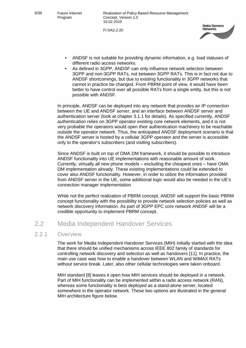
MIH standard [8] leaves it open how MIH services should be deployed in a network. Part of MIH functionality can be implemented within a radio access network (RAN), whereas some functionality is best deployed as a stand-alone server, located somewhere in the operator network. These two options are illustrated in the general MIH architecture figure below.
10/39 Future Internet Program
Realization of Policy-Based Resource Management Concept, Version 1.0 16.02.2010 FI DA2.2.20
Operator 1 3GPP RAN
Operator 1 WLAN RAN
Operator 2 WLAN RAN
UE
MIH Server
Operator 1 Core Network
RAN – Radio Access Network
MIH ServerOperator 2 Core Network
Figure 3. The general MIH architecture. 2.2.2 MIH Features
For information transfer between network elements, MIH standard relies on client-server model. In general, the UE is initiating all the transactions and contacts MIH server for the wanted action.
MIH provides three main types of services:
• Media Independent Information Service (MIIS) provides details on the characteristics and services provided by the serving and neighboring networks. UEs can use this information when making network selection and handover decisions. In practice, MIIS service matches pretty well with the PBRM concept and ANDSF service.
• Media Independent Command Service (MICS) enables managing and controlling link behavior relevant to handovers and mobility. In practice, MICS services are needed for realizing handover control.
• Media Independent Event Service (MIES) is used to convey information about various state or parameters’ changes on wireless links. MIES cannot be used as standalone service: instead, MIES is used together with MICS services for enabling handover control.
Information service (MIIS) is built around the same principles as PBRM concept and ANDSF: UE contacts MIIS server (can be implemented as a stand-alone server, or can co-locate in the same physical server with MICS and MIES services), fetches network selection policies and discovery information and stores it to be used in the coming network selection and handover decisions.
With MIIS services, it is possible to use both L2 and L3 solutions for information transport. L3 solution is a typical UDP or TCP based message transfer applicable for all RATs, but L2 solution requires support from RATs: currently, L2 solution has been

11/39 Future Internet Program
Realization of Policy-Based Resource Management Concept, Version 1.0 16.02.2010 FI DA2.2.20
defined within IEEE for WLAN (in draft 802.11u [12]) and WiMAX (in 802.16-2009 [13]). With L2 solution, the UE can send MIIS information request before making the actual network connection. The L2 mechanism could be used in a situation where the UE does not have prior MIIS information stored for the specific network: before the UE tries to connect to the network – and possibly fails in that – the UE could get MIIS information about the network in question and then decide should the connection to be tried or not. However, there is no support for L2 mechanism for other than IEEE RATs.
The main idea of MIH is that it could be used as a handover control entity in a heterogeneous network. The command and event services (MICS and MIES) are defined for this purpose: MIES service allows control entity to detect link related events in the UE, and MICS service provides protocol for control entity to trigger handovers. As the name of the standard implies, the approach has not been tied to any specific radio access technology. In general, however, the handover procedures are very time-sensitive: in order e.g. to support seamless handovers, the handover mechanism needs to be optimized for the given radio technology/technologies. When applying media-independent solution for something that is highly media-dependant, it is very difficult to achieve a well-working solution.
One big obstacle for MIH to be deployed as a generic handover control is not technical: the standardization bodies that define certain RAT tend to be protective for their own technology and are reluctant to adopt something defined elsewhere. Instead, different standardization bodies prefer defining their own solutions: for example, 3GPP has already defined its own interworking mechanisms between 3GPP and non-3GPP radio access technologies [5].
For WiMAX, the situation is a bit different from 3GPP family of technologies: currently, it seems the trend within WiMAX operators is to concentrate the business model around offering DSL-type of service, i.e. WiMAX is mainly used to provide Internet access for the subscribers. When abandoning the “cellular model” from WiMAX offering, it seems there is no much need from operator side for interoperability between WiMAX and other RATs. Thus, it is currently not probable MIH would be used as a handover service with either 3GPP or WiMAX networks.
But where MICS and MIES services in principle could be used is in the roaming between different WLAN networks. The existing WLAN specifications already define how mobility is handled when moving within a single network – identified by a certain SSID – but the mobility between different WLAN networks is not currently well covered in WLAN standards. The WLAN network selection mechanism is purely UE-centric: the UE is fully in charge for all the network selection decisions for WLAN networks. This model probably works well enough for non real-time services also between different WLAN networks, but not for real-time services, like voice. This is where MIH handover services could be used. However, in practice there is currently no need for WLAN – WLAN handovers between different operators, especially for real-time services. If such services are provided over WLAN, the same operator usually also has wide area network, e.g. 3GPP-based, and handovers are handled with other means then. Further, the suitability of MICS and MIES services for handovers of real-time applications is questionable.

12/39 Future Internet Program
Realization of Policy-Based Resource Management Concept, Version 1.0 16.02.2010 FI DA2.2.20
Thus, for the reasons provided above, it is not probable that MIH would be used for handover control technology between different RATs. This also means that MIES and MICS services of MIH will not probably be seen in real networks. However, this does not exclude providing only MIIS services in assisting UEs’ network selection decisions.
So far, MIH implementations have been limited to small scale trials and academic research work. To the knowledge of the authors, no commercial deployments of MIH features are announced. Since both WLAN and WiMAX support the possibility to access MIIS server via L2 mechanisms, it is possible that only MIIS service of MIH features could be deployed also in live WLAN and/or WiMAX networks in future.
2.2.3 Standardization Status
MIH standardization was initiated in late 2004. The standard was finally accepted in IEEE at the end of 2008, and the standard was published in January 2009. As discussed above, the standard specifies the three services – MIIS, MICS and MIES – and the messages used with them between the UE and MIH server. All interworking between MIH server and other network elements are excluded from the standard, i.e. the standard only covers UE – MIH server information exchange. Due to this, MIH cannot currently support e.g. roaming with interoperable functions across operator boundaries.
Another important aspect missing from the standard is how security of MIH is realized. Without a security solution, MIH cannot be deployed in real networks. However, a new working group 802.21a has been established to define the security framework for MIH. Currently, the group is evaluating different proposals, so no final results can be anticipated in near future.
Another new working group, 802.21b, was also formed to define handovers with downlink-only technologies, such as Digital Video Broadcasting (DVB). The work of this group has only started, so new amendments to the base 802.21 standard have to be waited for quite some time.
2.2.4 Realization of PBRM with MIH Since PBRM concept is not intended to be used as handover control service in heterogeneous network environment, MICS and MIES services of MIH standard are somewhat out of scope of the PBRM concept and they are not considered here.
In general, MIIS service of MIH standard corresponds PBRM concept quite well. MIIS can provide prioritized network selection information as well as pretty detailed network discovery information. For example, MIIS server can inform a UE about radio channel frequency information and link characteristic information in terms of achievable bitrates and available QoS. Also, MIIS service can indicate the cost of a network connection as part of network discovery information, although it is not at all specified how MIIS server obtains this information e.g. for the roaming subscribers. Overall, information MIIS server provides can be more detailed than ANDSF information.
It is not directly possible to deliver dynamic information – like load status of the network, or part of it – from MIIS server to the UE. However, MIIS server may provide information

13/39 Future Internet Program
Realization of Policy-Based Resource Management Concept, Version 1.0 16.02.2010 FI DA2.2.20
on QoS characteristics of the link layer. Basically, this could be used so that when the load status on the link changes, also the QoS characteristics MIIS server provides for that link are changed accordingly, thus enabling certain level of dynamicity with MIIS information.
As described in 2.2.2, it is possible to access MIIS server with both L2 and L3 based mechanisms. With IEEE RATs, this is a clear benefit over ANDSF. Since L3 MIH message transport is realized directly on top of UDP or TCP (look at chapter 4 for comparison of signaling load incurred between ANDSF and MIH), there are no extra delays caused by upper layers. If deployed, most probably MIIS service usage would follow the same pattern as ANDSF usage: information from the server is received well before the actual usage of the information and not in real-time.
Currently, the biggest handicap of the MIH standard is the lack of security solution. The work of 802.21a working group will hopefully solve this issue: no deployments in real networks can be made before a working security solution. Further, unlike with ANDSF, there are no existing implementations in the UEs or networks that could be reused for MIH deployments.
2.3 Summary In this chapter, two options to realize PBRM concept in a real network were considered. Basically, both ANDSF and MIH (or only MIIS service) can provide the same features as the PBRM concept on specification level. Although there are some differences on information provided in these two systems, the basic functionality of PBRM concept with network selection and network discovery information provisioning could be realized with either ANDSF or MIIS.
The motivation for ANDSF and MIH work has been a bit different. ANDSF is tied to 3GPP world and it is mainly a tool for the operators to facilitate the UEs’ network selection between 3GPP and non-3GPP accesses. ANDSF is intended to be used within a single operator network(s), i.e. the operator is in charge what information ANDSF provides. Of course, ANDSF also supports inter-operability between operators, but the ANDSF servers (of different operators) are independent from each other. So ANDSF can mainly be seen as a tool for the operator to influence UEs’ mobility within operator’s different networks and/or partner networks.
The starting point of MIH work was to develop a common handover mechanism over 802 family of (wireless) technologies. The work has mainly been technology-driven, and business aspects like operator requirements and real-life needs are not too much considered. In principle, MIH could be deployed – like ANDSF – as a tool for the operator. With MIIS, it is also possible to provide information over different operators’ networks. But who should provide such a service and what is the monetary value for the deploying organization? If for example the MIIS service provided information about random WLAN hotspots, it would mainly benefit the users, not the operators. But would the users be ready to pay something for this kind of service? That is questionable. As was discussed above in chapter 2.2.2, there are quite some challenges for MICS and MIES service being deployed. For MIIS service deployments, the MIIS service should bring some benefit for the deploying organization. Thus, the ANDSF-like operator model looks most promising also for the MIIS service, if an operator selects to use it.

14/39 Future Internet Program
Realization of Policy-Based Resource Management Concept, Version 1.0 16.02.2010 FI DA2.2.20
When considering real deployment scenarios in a live network, there is clear difference between ANDSF and MIH: ANDSF is specified as part of 3GPP EPC core network, but MIH is defined as an overlay solution without any links to real life network deployments. ANDSF can easily be deployed in 3GPP core network with UE implementations building on top of existing OMA DM implementations. There is currently no existing infrastructure or terminal support that could be reused when deploying MIH (or MIIS) services. Further, it is very unlikely MIH could be used together with 3GPP defined networks, when 3GPP offers similar, competing solution.
Almost all the major wireless operators have indicated that they will adopt 3GPP LTE radio access technology together with ECP core network. This opens numerous deployment possibilities also for the ANDSF service. Many operators have expressed their interest on ANDSF, although there are no final commitments to deploy it yet. Currently, it seems that ANDSF will be the solution to realize PBRM concept in real networks.

15/39 Future Internet Program
Realization of Policy-Based Resource Management Concept, Version 1.0 16.02.2010 FI DA2.2.20
3. PBRM Server Interworking with Other Network Elements The previous papers around PBRM topic ([1], [2], [3] and [4]) have mainly been covering the internal functionality of PBRM concept and what information is exchanged between the UEs and PBRM server. However, when a PBRM type of service is deployed in a real network, a PBRM server has to interact with various other network elements in order to realize a working service for the network users: for example, PBRM server may need an access to subscriber-specific data bases, interworking with existing security machinery, etc.
In this chapter, the interworking of PBRM server with other core network elements is discussed. To put this discussion into more concrete context, PBRM deployments based on possible real-life options are considered: as concluded on the previous chapter, out of the two possibilities, ANDSF is more potential choice. Thus, this chapter mainly concentrates around ANDSF and 3GPP EPC, although also MIH security solution options are covered in security aspects discussion.
Currently, ANDSF specifications define only the S14 interface between the UE and ANDSF server. Also, security architecture has been defined for ANDSF. However, all other interworking with EPC core network elements has been excluded from ANDSF specifications. In this chapter, the need for this interworking is discussed. Chapter 3.1 describes security solutions for both ANDSF and MIH. Then, on chapter 3.2 ANDSF interfaces towards the existing subscriber databases are discussed, and finally ANDSF interworking with QoS assuring mechanisms of 3GPP EPC core network is considered on chapter 3.3.
3.1 Security Framework Since PBRM concept can be used to influence the UE’s network selection, it is a powerful tool that may affect both the operator’s revenues and the costs the subscriber is paying for a network access. Thus, the PBRM service has to be deployed with sufficient security mechanisms. The following high-level requirements are applicable for the communication between the UEs and PBRM server:
• UE and PBRM shall be mutually authenticated • The UE shall be able to verify that the PBRM server is authorized to serve it • Signaling between the UE and PBRM server shall be integrity and confidentiality
protected, and protected against possible replay attacks
In the following, it is discussed how these requirements are fulfilled for 3GPP-defined ANDSF and IEEE-defined MIH frameworks.
3.1.1 Generic Authentication Architecture for ANDSF 3.1.1.1 Overview
As described on chapter 2.1.2, the S14 interface between UE and ANDSF server is based on OMA DM. In OMA DM, the provisioning server – i.e. ANDSF server – needs to be bootstrapped to the UE before the UE is able to access the ANDSF server. In this

16/39 Future Internet Program
Realization of Policy-Based Resource Management Concept, Version 1.0 16.02.2010 FI DA2.2.20
process the UE is brought into a state where it can initiate connection with a specific server. OMA DM doesn’t mandate any specific bootstrap process as long as it fulfills the given security requirements.
Within 3GPP standardization, it was noticed that a number of applications share a need for mutual authentication between the client (i.e. the UE) and an application server before the communication can take place. For these applications, a common authentication framework has been defined. This framework is called Generic Authentication Architecture (GAA). The GAA architecture is described in 3GPP specification 33.220 [14].
ANDSF security solution is built on GAA framework and implements PSK-TLS based mutual authentication and ciphering solution described in 3GPP specification 33.222 [15] Usage details for GAA are specified in 24.109 [22]. This ANDSF security solution fulfills the security requirements for the OMA DM bootstrap process.
3.1.1.2 GAA Architecture
In the GAA architecture, the following network components are included: UE, Bootstrap Server Functionality (BSF), Operator controlled Network Application Functionality (NAF), Home Subscriber System (HSS) and Zn-Proxy for operator interface in case of roaming scenario. In the concept, ANDSF takes the role of NAF, and is thus required to have a new interface Zn towards the BSF server. Zn-Proxy is only used when the UE is communicating with a visited ANDSF (V-ANDSF); this discussion concentrates on the basic home scenario where Zn-Proxy is not needed. The GAA architecture is illustrated on Figure 4.
Figure 4. GAA architecture with roaming support. [14]
GAA makes use of the already deployed and widely used GSM authentication system to avoid the duplication of the credentials: in GAA, 3GPP AKA –based general mechanism is used to install a common shared secret between a UE and a server, i.e.
17/39 Future Internet Program
Realization of Policy-Based Resource Management Concept, Version 1.0 16.02.2010 FI DA2.2.20
ANDSF. This common share secret is then subsequently used to secure communications and further application data exchange between the UE and ANDSF server.
The BSF server is the central entity in GAA architecture: BSF server delivers the application-independent mechanism for providing the common shared secret for the UE and ANDSF server, as shortly described above. The same BSF functionality can be used for setting up security for different applications having similar kinds of security requirements as ANDSF. In addition to ANDSF, the GAA architecture is used in 3GPP for example with Mobile Broadcast / Multicast Service (MBMS) and presence server.
One of the benefits of GAA is that it is based on well-known existing security mechanisms. TLS (or HTTPS) is supported widely both on the UEs and network servers.
3.1.1.3 Using GAA with ANDSF
GAA security is based on the use of 3GPP AKA algorithm and HTTPS to create shared common secrets for the UE and ANDSF server to subsequently enable PSK-TLS communication between them.
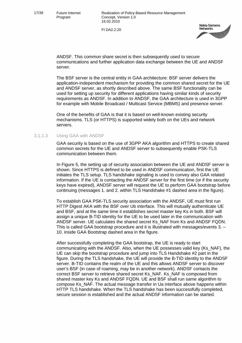
In Figure 5, the setting up of security association between the UE and ANDSF server is shown. Since HTTPS is defined to be used in ANDSF communication, first the UE initiates the TLS setup. TLS handshake signaling is used to convey also GAA related information. If the UE is contacting the ANDSF server for the first time (or if the security keys have expired), ANDSF server will request the UE to perform GAA bootstrap before continuing (messages 1. and 2. within TLS Handshake #1 dashed area in the figure).
To establish GAA PSK-TLS security association with the ANDSF, UE must first run HTTP Digest AKA with the BSF over Ub interface. This will mutually authenticate UE and BSF, and at the same time it establishes secret master key Ks in both. BSF will assign a unique B-TID identity for the UE to be used later in the communication with ANDSF server. UE calculates the shared secret Ks_NAF from Ks and ANDSF FQDN. This is called GAA bootstrap procedure and it is illustrated with messages/events 3. – 10. inside GAA Bootstrap dashed area in the figure.
After successfully completing the GAA bootstrap, the UE is ready to start communicating with the ANDSF. Also, when the UE possesses valid key (Ks_NAF), the UE can skip the bootstrap procedure and jump into TLS Handshake #2 part in the figure. During the TLS handshake, the UE will provide the B-TID identity to the ANDSF server. B-TID contains the realm of the UE and this allows ANDSF server to discover user’s BSF (in case of roaming, may be in another network). ANDSF contacts the correct BSF server to retrieve shared secret Ks_NAF. Ks_NAF is composed from shared master key Ks and ANDSF FQDN. UE and BSF shall run same algorithm to compose Ks_NAF. The actual message transfer in Ua interface above happens within HTTP TLS handshake. When the TLS handshake has been successfully completed, secure session is established and the actual ANDSF information can be started.

18/39 Future Internet Program
Realization of Policy-Based Resource Management Concept, Version 1.0 16.02.2010 FI DA2.2.20
HSSBSFANDSFUE1. TLS: ClientHello
2. TLS: ServerKeyExchange: 3GPP-bootstrapping
3. HTTP-Req (user id)4. BSF retrieves AuthVectorand User profile5. HTTP-Rsp: 401 Unauthorized WWW-Authenticate: Digest(RAND,AUTN)
7. HTTP-Req Authorization: Digest (RES is used)
9. HTTP-Rsp: 200 OK AuthenticationInfo (B-TID, KeyLifetime)
12. TLS: ClientKeyExchange (B-Tid)13. Auth Request (B-Tid, NAF_Id)
15. Auth Response (Ks_NAF, KeyLifetime, User profile)
17. TLS: ChangeCipherSuite &
Finished
S14 / Ua Zn Zh
Ub
6. Client run AKA algorithms, verifies AUTN, derives RES and key
8. Server verifies RES, generates key Ks_NAF and saves record
10. Client generates Ks_NAF
GAA Boot-strap
14. Server search record by B-Tid, generates Ks_NAF
16. Server stores Ks_NAF, KeyLifetime, User profile
TLS Hand-shake #1
...
TLS Hand-shake #2
11. TLS Message exchange
...
18. ANDSF information exchange
Figure 5. GAA security association setup for ANDSF with bootstrapping. 3.1.2 MIH Security
The security requirements listed on chapter 3.1 for PBRM server are also applicable for Media Independent Information Service (MIIS) of MIH. Those requirements, however, do not cover other MIH services’ – MICS and MIES – requirements. Since MICS and MIES are dealing with handover signaling, possible crossing operator boundaries, the requirements for those are completely different.
Initially, in MIH standardization it was seen that “security is hard, so steer clear of it for now” [11]. Due to this, the basic MIH standard [8] does not include any security solution. For a service like MIH, this is really a limiting factor: in practice, MIH cannot be deployed in real networks before a well-defined security mechanism has been introduced.
Newly established IEEE working group 802.21a is working on the missing security solution. The working group has more or less managed to agree on the requirements for MIH security. It seems the work so far has concentrated mostly on MICS and MIES

19/39 Future Internet Program
Realization of Policy-Based Resource Management Concept, Version 1.0 16.02.2010 FI DA2.2.20
services, though. For MIIS, it is basically only identified that mutual authentication is required, and the signaling needs to be encrypted. However, how this is realized in practice is currently completely open.
So far, 802.21a working group has not published any draft specification. The working group has studied the different “media-specific” security solutions used with various radio access technologies. It seems there are two different high-level approaches for MIH security: adding media-independent solution over existing media-specific mechanism, or replacing existing media-specific mechanism(s) with media-independent solution. The first one is very hard to do, and the second one is not realistic. How 802.21a working group will solve this situation mainly related to MICS and MIES services, is not yet known. Hopefully the working group will not get stuck with that, or there is a danger that also MIIS security solution will remain undefined.
For MIIS service, the situation should be a bit easier. For example, the existing GAA-based security architecture could also be applied with MIIS. Of course, this means that it would be possible to use MIIS only with the UEs having 3GGP AKA support and with the networks based on 3GPP EPC architecture. However, since it is possible to use the same EPC core network also with WLAN and WiMAX, this may be no limiting factor at all.
According to 802.21a meeting minutes on the working group document repository [16], the number of participants on the meetings is pretty low. This may indicate that there is low interest on completing the MIH standard, and is definitively not encouraging for the hopes that MIH could be deployable with a working security solution some day in near future.
3.2 Subscriber Database
3.2.1 Overview
In PBRM concept, if the PBRM server is intended to provide some subscriber-specific information – e.g. different network selection policies for each subscriber – the PBRM server is required to have an access to some subscriber database. Currently, neither ANDSF nor MIIS (MIH) provides subscriber-specific information as such: one practical obstacle for that is the lack of standardized interface towards a subscriber database.
Especially with cellular networks, the number of subscribers and data stored for each can be huge. Subscriber database is one of the most important assets of the operator, and managing and access of that database is strictly controlled. In 3GPP EPC architecture, Home Subscriber Server (HSS) is the subscription data repository for all permanent user data (refer to Figure 1). The interfaces to access HSS data are standardized.
The HSS stores the master copy of the subscriber profile, which contains information about the services that are applicable to the user, including information about the allowed network connections, and whether roaming to a particular visited network is allowed or not. For supporting mobility with non-3GPP access networks (e.g. WLAN), the HSS also stores the identities of those PDN GWs that are in use for the subscriber.

20/39 Future Internet Program
Realization of Policy-Based Resource Management Concept, Version 1.0 16.02.2010 FI DA2.2.20
Also all the security information of the subscriber is maintained in HSS. As well, the HSS stores the current location of the UE on PDN GW level.
Although not currently included in ANDSF specification, ANDSF could easily be used to deliver subscriber-specific information. For example, operator could define certain number of user classes for which a different set of ANDSF information is provided: e.g. gold users could use any access with all services, silver users would be allowed to use P2P protocols only over WLAN network, etc. Also, if ANDSF provided information related for the subscriber home access (e.g. for home WLAN), the ANDSF should be able to find out the subscriber identity and related information. To enable these use scenarios, ANDSF should have access to home subscriber database, e.g. HSS. Defining a new interface between ANDSF and HSS can be a tedious process and it is unlikely to happen. Instead, a new concept to access subscriber data called User Data Convergence (UDC) has been defined in 3GPP.
3.2.2 User Data Convergence
In the current 3GPP system, user data is scattered in several domains (e.g. CS, PS, IMS) and different network entities (e.g. HSS, different Application Servers). With the increase of user data entities and the resulting data types, it is more difficult for new services to access necessary user information from plural entities. To tackle this, the User Data Convergence was introduced.
The basic idea of the User Data Convergence (UDC) is to separate the storage of the user data from the applications using the data, i.e. different network elements, like HSS, and application servers, etc. The essential part of the UDC is User Data Repository (UDR) that centrally stores all the user data currently scattered in different parts of the network. UDR provides a common way for accessing, storing and managing the data stored in the repository. In the following figure, the general idea of UDC is illustrated.
Current status User Data Convergence
Figure 6. The general idea of User Data Convergence. [17]
In UDC concept, the applications and network entities can access the user data repository via application front ends (FE). Each application and network entity may have an application FE of its own, and the application FE can provide different views on the

21/39 Future Internet Program
Realization of Policy-Based Resource Management Concept, Version 1.0 16.02.2010 FI DA2.2.20
stored user data depending on the type of application or network entity accessing the UDR data. The UDC reference architecture is shown on Figure 7.
Ud
Application(s) front end
UDR
Diameter based ref points (e.g. Cx, Sh,
S6a/S6d)
MAP based ref points (e.g. C, D,
Gr)
SIP based ref points
UE, Core Network, Service Layer & OSS
UDC
Application(s) front end Application(s) front end
Other ref points
UE ref points (e.g. OMA
DM based S14, Ut )
Figure 7. UDC reference architecture. [ 018]
In the UDC architecture, only the central user data repository – UDR – shall store the actual user data. Application FEs can fetch and modify data, but the modified data shall immediately be updated to the UDR. This way, other application FEs can also see the newly modified data.
As shown in the figure above, the reference point Ud has been defined between the application FEs and UDR. The information flows for Ud reference point are defined in 3GPP TS 23.335 [18]. Logically, application FEs are part of UDC architecture, but the implementation of a specific application FE depends on the type of FE. For example, HSS FE may reside in a physically separate cluster that the other network entities can access using the normal HSS interfaces. If UDC was applied for ANDSF, then the ANDSF front end would most probably be implemented in ANDSF server itself, and the interface between ANDSF and UDR would be based on Ud specification.
3.2.3 Using UDC with ANDSF Currently, ANDSF does not support subscriber-specific information provisioning. However, with UDC concept it would be easy to introduce the required functionality for that in ANDSF. Depending on the usage of ANDSF, the ANDSF server may need access to various kinds of data: network selection policies, network discovery information, location database for access networks, etc. For general PBRM concept, these were discussed in [3].

22/39 Future Internet Program
Realization of Policy-Based Resource Management Concept, Version 1.0 16.02.2010 FI DA2.2.20
Since the above listed information is specific to ANDSF, it is probably best to store that information in the ANDSF server itself. If an operator wished to provision e.g. subscriber-specific network selection policies to the UEs, the following scheme could be used:
• It is probably not necessary to define different network selection policies for each subscriber separately: instead, the operator could define a certain number of sets of different network selection policies and then assign each subscriber to one (or more) of these sets.
• For each subscriber, the subscriber identity and the assigned set of network selection policies (indicated e.g. with an integer) is stored into UDR
• When the subscriber / UE contacts ANDSF for subscriber-specific information, the ANDSF server will fetch subscriber-specific information (subscriber id and integer indication for the assigned set of policy) via Ud interface from UDR.
• ANDSF combines the information stored in its own database and information received from UDR. ANDSF delivers the subscriber-specific set of network selection policy.
With the scheme described above, it is possible to keep the subscriber-specific data stored in UDR simple, and maintain more complex database close to the ANDSF server itself. The same principled could also be applied to other ANDSF subscriber-specific information provisioning.
3.3 Policy and Charging Control
3.3.1 Overview
Policy and Charging Control (PCC) is part of EPC architecture. PCC provides operators advanced tools for service-aware QoS and charging control. The main function of the PCC is to manage QoS of each connection established through the EPC, and also to ensure that the agreed QoS level is maintained in spite of changing conditions (e.g. handovers). PCC is also used for various charging-related tasks, e.g. to check in real-time that there are enough credits to establish a new connection, etc. Charging aspects of PCC are not further considered in this document.
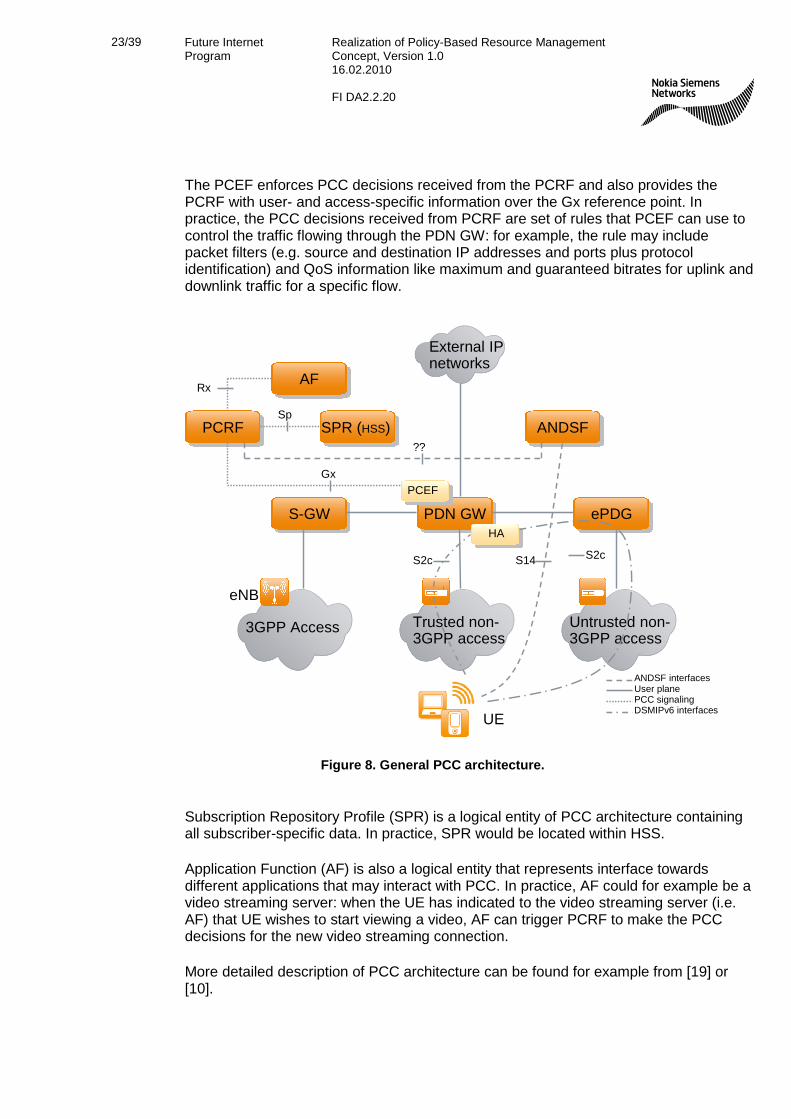
The general PCC architecture is shown on Figure 8. The figure is a bit simplified, for example the interfaces to charging functions have been omitted. The figure represents so called “on-path” alternative, where Bearer Binding and Event Reporting Functions (BBERF) located in either in S-GW (for 3GPP accesses) or access gateways (non-3GPP accesses) are not used.
Policy and Charging Rules Function (PCRF) is the central PCC architecture entity, and it can be considered as control function for the whole PCC. PCRF combines the session information received over Rx reference point and the input from Policy and Charging Enforcement Function (PCEF) over Gx reference point with user-specific policies and data from the Subscription Repository Profile (SPR). From that information, PCRF forms session-level “PCC decisions” and provides those to the PCEF. The PCRF also forwards events between PCEF and Application Function (AF).
23/39 Future Internet Program
Realization of Policy-Based Resource Management Concept, Version 1.0 16.02.2010 FI DA2.2.20
The PCEF enforces PCC decisions received from the PCRF and also provides the PCRF with user- and access-specific information over the Gx reference point. In practice, the PCC decisions received from PCRF are set of rules that PCEF can use to control the traffic flowing through the PDN GW: for example, the rule may include packet filters (e.g. source and destination IP addresses and ports plus protocol identification) and QoS information like maximum and guaranteed bitrates for uplink and downlink traffic for a specific flow.
3GPP Access Trusted non-3GPP access
Untrusted non-3GPP access
S-GW
External IP networks
PDN GW ePDG
UE
ANDSFPCRF
eNB
S14
AFRx
SPR (HSS)Sp
Gx
??
PCEF
HA
ANDSF interfacesUser planePCC signalingDSMIPv6 interfaces
S2c S2c
Figure 8. General PCC architecture.
Subscription Repository Profile (SPR) is a logical entity of PCC architecture containing all subscriber-specific data. In practice, SPR would be located within HSS.
Application Function (AF) is also a logical entity that represents interface towards different applications that may interact with PCC. In practice, AF could for example be a video streaming server: when the UE has indicated to the video streaming server (i.e. AF) that UE wishes to start viewing a video, AF can trigger PCRF to make the PCC decisions for the new video streaming connection.
More detailed description of PCC architecture can be found for example from [19] or [10].
24/39 Future Internet Program
Realization of Policy-Based Resource Management Concept, Version 1.0 16.02.2010 FI DA2.2.20
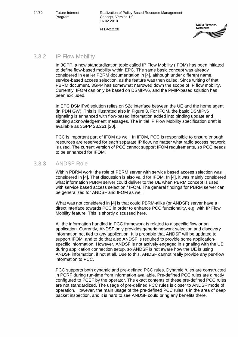
3.3.2 IP Flow Mobility
In 3GPP, a new standardization topic called IP Flow Mobility (IFOM) has been initiated to define flow-based mobility within EPC. The same basic concept was already considered in earlier PBRM documentation in [4], although under different name, service-based access selection, as the feature was then called. Since writing of that PBRM document, 3GPP has somewhat narrowed down the scope of IP flow mobility. Currently, IFOM can only be based on DSMIPv6, and the PMIP-based solution has been excluded.
In EPC DSMIPv6 solution relies on S2c interface between the UE and the home agent (in PDN GW). This is illustrated also in Figure 8. For IFOM, the basic DSMIPv6 signaling is enhanced with flow-based information added into binding update and binding acknowledgement messages. The initial IP Flow Mobility specification draft is available as 3GPP 23.261 [20].
PCC is important part of IFOM as well. In IFOM, PCC is responsible to ensure enough resources are reserved for each separate IP flow, no matter what radio access network is used. The current version of PCC cannot support IFOM requirements, so PCC needs to be enhanced for IFOM.
3.3.3 ANDSF Role
Within PBRM work, the role of PBRM server with service based access selection was considered in [4]. That discussion is also valid for IFOM. In [4], it was mainly considered what information PBRM server could deliver to the UE when PBRM concept is used with service based access selection / IFOM. The general findings for PBRM server can be generalized for ANDSF and IFOM as well.
What was not considered in [4] is that could PBRM-alike (or ANDSF) server have a direct interface towards PCC in order to enhance PCC functionality, e.g. with IP Flow Mobility feature. This is shortly discussed here.
All the information handled in PCC framework is related to a specific flow or an application. Currently, ANDSF only provides generic network selection and discovery information not tied to any application. It is probable that ANDSF will be updated to support IFOM, and to do that also ANDSF is required to provide some application-specific information. However, ANDSF is not actively engaged in signaling with the UE during application connection setup, so ANDSF is not aware how the UE is using ANDSF information, if not at all. Due to this, ANDSF cannot really provide any per-flow information to PCC.
PCC supports both dynamic and pre-defined PCC rules. Dynamic rules are constructed in PCRF during run-time from information available. Pre-defined PCC rules are directly configured to PCEF by the operator. The exact contents of these pre-defined PCC rules are not standardized. The usage of pre-defined PCC rules is closer to ANDSF mode of operation. However, the main usage of the pre-defined PCC rules is in the area of deep packet inspection, and it is hard to see ANDSF could bring any benefits there.

25/39 Future Internet Program
Realization of Policy-Based Resource Management Concept, Version 1.0 16.02.2010 FI DA2.2.20
In general, although not knowing what application-specific information ANDSF will be able to provide in future, it does not seem probable that the information ANDSF could provide was not available already to PCC via PCC framework normal information flows. Thus, currently the interface between ANDSF and PCC seems to be unnecessary.

26/39 Future Internet Program
Realization of Policy-Based Resource Management Concept, Version 1.0 16.02.2010 FI DA2.2.20
4. PBRM Signaling Load In this chapter, it is considered how much signaling traffic PBRM information exchange between the UE and server would create on a network. Several factors affect this: is PBRM server accessed in real-time e.g. during handover execution or not, how often a UE contacts the PBRM server, what kind of and how much information PBRM server provides, etc. Just like the previous chapters, also here the discussion is based on the possible real-life realizations of PBRM concept: since ANDSF seems to be much more viable solution compared to MIH, this chapter mostly considers PBRM signaling load from ANDSF point of view. However, also some estimation on corresponding MIH signaling is given as a comparison.
4.1 ANDSF Signaling The ANDSF information is transferred between the UE and ANDSF server using OMA DM framework. Before going to the discussion on the signaling load, some basics of the OMA DM framework are discussed.
4.1.1 OMA DM Framework
The Device Management (DM) is defined by Open Mobile Alliance (OMA) in [21]. That specification is only a container having references to other OMA DM specifications where the actual DM functionality is defined.
The idea of Device Management is to relieve the user from the burden of configuring all the required settings to the UE: instead, the DM server will provide the necessary configuration information and the DM client on the UE takes that information into use on the UE. With DM, it is possible for the third parties (mobile operators, service providers, corporate IT-departments) to remotely provision new services, configure and manage the UE parameters and settings, and troubleshoot UEs.
4.1.1.1 Data Model
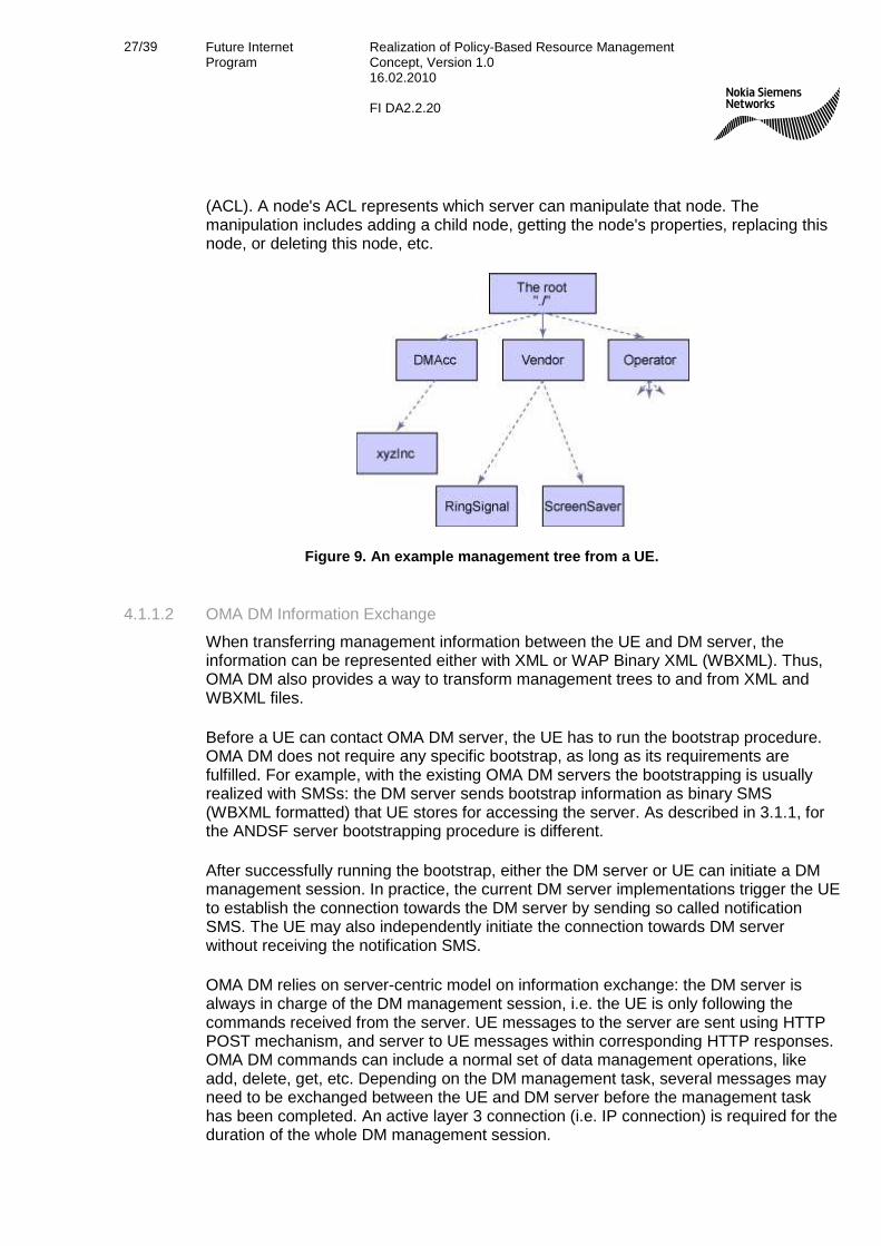
Each UE supporting OMA DM has a management tree. The management tree (see Figure 9 for an example) contains and organizes all the available management objects so that both the UE and DM server can access every node directly through a unique URI. For example, to access the "xyzInc" node in the figure, the correct URI is “./DMAcc/xyzInc”.
Another important term related to OMA DM data model is the management object (MO). Management objects are stored into the management tree on the UE. Management object is a collection of data related to a specific application or service. For example, OMA DM defines three mandatory MOs that each UE and server has to implement. These mandatory MOs are use to represent information related to the type of terminal like manufacturer, model, etc. Also, ANDSF specification defines its own MO.
In the management tree, nodes are entities that can be manipulated through the OMA DM protocol. An interior node can have an unlimited number of child nodes, while a leaf node must contain a value. Each node has a set of run-time properties associated with it. All properties are only valid for the associated node, except the Access Control List
27/39 Future Internet Program
Realization of Policy-Based Resource Management Concept, Version 1.0 16.02.2010 FI DA2.2.20
(ACL). A node's ACL represents which server can manipulate that node. The manipulation includes adding a child node, getting the node's properties, replacing this node, or deleting this node, etc.
Figure 9. An example management tree from a UE.
4.1.1.2 OMA DM Information Exchange
When transferring management information between the UE and DM server, the information can be represented either with XML or WAP Binary XML (WBXML). Thus, OMA DM also provides a way to transform management trees to and from XML and WBXML files.
Before a UE can contact OMA DM server, the UE has to run the bootstrap procedure. OMA DM does not require any specific bootstrap, as long as its requirements are fulfilled. For example, with the existing OMA DM servers the bootstrapping is usually realized with SMSs: the DM server sends bootstrap information as binary SMS (WBXML formatted) that UE stores for accessing the server. As described in 3.1.1, for the ANDSF server bootstrapping procedure is different.
After successfully running the bootstrap, either the DM server or UE can initiate a DM management session. In practice, the current DM server implementations trigger the UE to establish the connection towards the DM server by sending so called notification SMS. The UE may also independently initiate the connection towards DM server without receiving the notification SMS.
OMA DM relies on server-centric model on information exchange: the DM server is always in charge of the DM management session, i.e. the UE is only following the commands received from the server. UE messages to the server are sent using HTTP POST mechanism, and server to UE messages within corresponding HTTP responses. OMA DM commands can include a normal set of data management operations, like add, delete, get, etc. Depending on the DM management task, several messages may need to be exchanged between the UE and DM server before the management task has been completed. An active layer 3 connection (i.e. IP connection) is required for the duration of the whole DM management session.

28/39 Future Internet Program
Realization of Policy-Based Resource Management Concept, Version 1.0 16.02.2010 FI DA2.2.20
The message sizes transferred with OMA DM are about equal size in both directions: first, the management tree information is transferred from the server to the UE, and then UE acknowledges the same information back to the server with the full management tree information, as described in chapter 4.1.1.3.
Normally, setting up an OMA DM management session takes some time: the UE and DM server are mutually authenticated and then the mandatory management objects are transferred from the UE to DM server. This can easily take several seconds. After that, the actual DM information exchange may require several messages to be exchanged (as we will see in chapter 4.1.2), again taking possibly several seconds. It should be noted that not only the information exchange itself but also the processing of each OMA DM message takes some processing time on both ends, and that also contributes to the total management session duration. Due to these inherent features, OMA DM is not really suitable for real-time data transfer. This also applies to ANDSF that relies on OMA DM framework.
4.1.1.3 An Example DM Management Session
As a real-life example, a DM management Session between Nokia N95 and a DM server was recorded. In this example, the DM server provides settings for so called Internet Access Point (AP) management object. In the following figure, the contents of the AP MO of the example are shown in textual format.
./AP/<X>
./AP/<X>/NAPDef
./AP/<X>/NAPDef/<X>
./AP/<X>/NAPDef/<X>/Name
./AP/<X>/NAPDef/<X>/Bearer
./AP/<X>/NAPDef/<X>/Bearer/<X>/
./AP/<X>/NAPDef/<X>/Bearer/<X>/BearerL
./AP/<X>/NAPDef/<X>/Bearer/<X>/Direction
./AP/<X>/NAPDef/<X>/WLAN
./AP/<X>/NAPDef/<X>/WLAN/<X>
./AP/<X>/NAPDef/<X>/WLAN/<X>/SSID
./AP/<X>/NAPDef/<X>/WLAN/<X>/NetworkMode
./AP/<X>/NAPDef/<X>/WLAN/<X>/SecurityMode
./AP/<X>/NAPDef/<X>/WLAN/<X>/UseWPAPSK
./AP/<X>/NAPDef/<X>/WLAN/<X>/WPAPreSharedKey
./AP/<X>/NAPDef/<X>/WLAN/<X>/WEPKeyIndex
./AP/<X>/NAPDef/<X>/WLAN/<X>/WEPAuthMode
./AP/<X>/NAPDef/<X>/WLAN/<X>/WEPKey
./AP/<X>/NAPDef/<X>/WLAN/<X>/WEPKey/<X>
./AP/<X>/NAPDef/<X>/WLAN/<X>/WEPKey/<X>/WEPKeyID
./AP/<X>/NAPDef/<X>/WLAN/<X>/WEPKey/<X>/Data
./AP/<X>/NAPDef/<X>/NAPAddr
./AP/<X>/NAPDef/<X>/NAPAddrTy
./AP/<X>/NAPDef/<X>/DNSAddr
./AP/<X>/NAPDef/<X>/DNSAddr/<X>
./AP/<X>/NAPDef/<X>/DNSAddr/<X>/DNSAddrL
./AP/<X>/NAPDef/<X>/DNSAddr/<X>/DNSPriority
Figure 10. An example of Internet Access Point (AP) management object.

29/39 Future Internet Program
Realization of Policy-Based Resource Management Concept, Version 1.0 16.02.2010 FI DA2.2.20
During the DM management session, the contents of the management object are placed on the management tree of the UE. The ‘<X>’ symbols are replaced with DM server-selected strings during run-time. For each object shown above the DM server will allocate a value, e.g. the leaf ./AP/<X>/NAPDef/<X>/WLAN/<X>/SSID will store the SSID of a specific WLAN network, etc.
A screenshot from the DM management session is also shown in Figure 11. In the figure, the server is sending the contents of the Internet Access Point MO to the UE coded in WBXML and transmitted within HTTP. Although the HTTP messages are coded with WBXML, the messages are still pretty big. For example, the message shown in Figure 9 is in total 3 361 bytes long containing the whole Internet AP MO to be stored into the UE.
Figure 11. Screenshot from DM management session capture.
30/39 Future Internet Program
Realization of Policy-Based Resource Management Concept, Version 1.0 16.02.2010 FI DA2.2.20
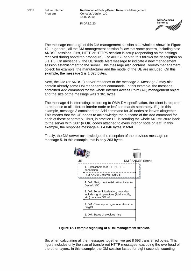
The message exchange of this DM management session as a whole is shown in Figure 12. In general, all the DM management session follow this same pattern, including also ANDSF sessions. First, HTTP or HTTPS session is setup (depending on the settings received during bootstrap procedure). For ANDSF server, this follows the description on 3.1.1.3. On message 2, the UE sends Alert message to indicate a new management session establishment to the server. This message also contains DevInfo management object: for example, the manufacturer and the model of the UE are included. On this example, the message 2 is 1 023 bytes.
Next, the DM (or ANDSF) server responds to the message 2. Message 3 may also contain already some DM management commands. In this example, the message contained Add command for the whole Internet Access Point (AP) management object, and the size of the message was 3 361 bytes.
The message 4 is interesting: according to OMA DM specification, the client is required to response to all different interior node or leaf commands separately. E.g. in this example, message 3 contained the Add command for 40 nodes or leaves altogether. This means that the UE needs to acknowledge the outcome of the Add command for each of these separately. Thus, in practice UE is sending the whole MO structure back to the server with ‘200’ (= OK) codes attached to every interior node or leaf. In this example, the response message 4 is 4 046 bytes in total.
Finally, the DM server acknowledges the reception of the previous message on message 5. In this example, this is only 263 bytes.
DM / ANDSF ServerUE
1. Establishment of HTTP/HTTPS connection
2. DM: Alert, client initialization, includes DevInfo MO
3. DM: Server initialization, may also include mgmt operations (Add, modify, etc.) on some DM info
4. DM: Client rsp to mgmt operations on msg#3
5. DM: Status of previous msg
For ANDSF, follows Figure 5.
Figure 12. Example signaling of a DM management session.
So, when calculating all the messages together, we get 8 693 transferred bytes. This figure includes only the size of transferred HTTP messages, excluding the overhead of the other layers. In this example, the DM session lasted for eight seconds, counting
31/39 Future Internet Program
Realization of Policy-Based Resource Management Concept, Version 1.0 16.02.2010 FI DA2.2.20
from the sending of message 2 from the UE. The setup phase further increases the total duration.
Although the management object structure transferred here was somewhat large, this example shows that OMA DM is not very efficient on information exchange. The session lasted for several seconds, and the amount of data transferred is counted in kilo bytes. However, it should be noted that time spent on UE in processing the messages is considerably longer than time spent on the server side. So in this example, the UE implementation of OMA DM is the biggest factor contributing to the total session duration. It is also clearly visible from this example that OMA DM is not intended for real-time information exchange.
In principle, OMA DM supports also compression for the data values, but it seems that at least the tested UEs do not implement it currently. If all the compression options of WBXML are used, it is possible to compress the total message sizes roughly to about one third of the originals. But even then, we are talking about message sizes of kilo bytes.
4.1.2 ANDSF Signaling Load 4.1.2.1 ANDSF Management Object
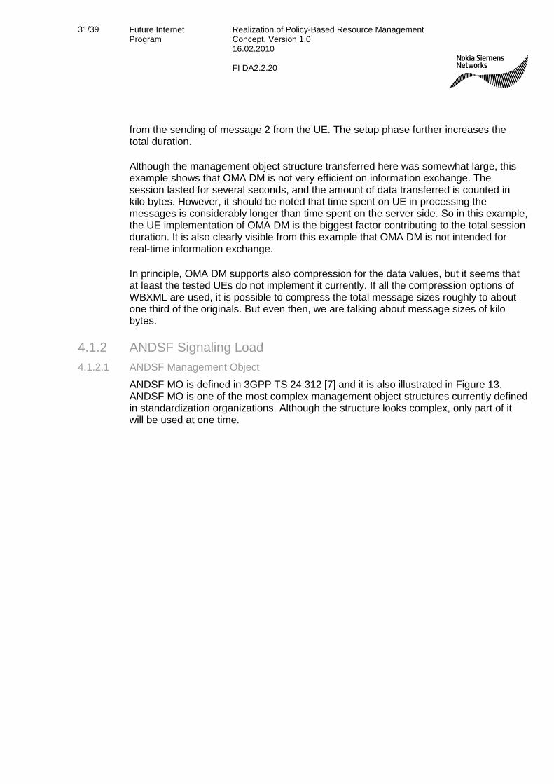
ANDSF MO is defined in 3GPP TS 24.312 [7] and it is also illustrated in Figure 13. ANDSF MO is one of the most complex management object structures currently defined in standardization organizations. Although the structure looks complex, only part of it will be used at one time.

32/39 Future Internet Program
Realization of Policy-Based Resource Management Concept, Version 1.0 16.02.2010 FI DA2.2.20
Network selection policies• Validity constraints
Network discovery info
Figure 13. ANDSF Management Object [7].
The most important part of MO is the network selection policies that are defined under interior node PrioritizedAccess that can hold a list of accesses defined by access technology type, possible access ID (e.g. for WLAN SSID is here) and the actual priority. When making the network selection, UE should consider first the access with the highest priority under PrioritizedAccess.
In ANDSF MO, network selection policies may have two kinds of constraints, either based on location (under interior node ValidityArea) or time (under TimeOfDay). If there are validity constraints defined for a given network selection policy, only the valid ones can be considered during the network selection process.
ANDSF MO defines the network discovery information under the interior node DiscoveryInformation. The actual access technology –specific information is stored under a reference AccessNetworkInformationReference that points to another MO. For example, the network discovery information for WLAN is defined in MO specified by OMA DM.
33/39 Future Internet Program
Realization of Policy-Based Resource Management Concept, Version 1.0 16.02.2010 FI DA2.2.20
4.1.2.2 ANDSF Accessing Scenarios
ANDSF specification does not define, when a UE should contact the ANDSF server, it is up to the UE manufacturers and operators to decide. Since ANDSF cannot be used for real-time information exchange, the main usage for the UEs is to access ANDSF server after some triggers that are implementation dependant. Some of the possible triggers are listed below:
• UE turned on: ANDSF is accessed only when the UE is turned on. There may be some timer to forbid access to ANDSF too often.
• Time-based: ANDSF is accessed once every day e.g. for rush hour policies, or once a week, month or year.
• Location-based: when the UE changes some specific location area, e.g. location area / tracking area or PLMN.
Depending on the usage of the ANDSF service, the operator may prefer the UE manufacturers to support all the triggers above. However, here we assume that the operator intends to keep ANDSF information fairly static, and it is enough to contact the ANDSF server once per week.
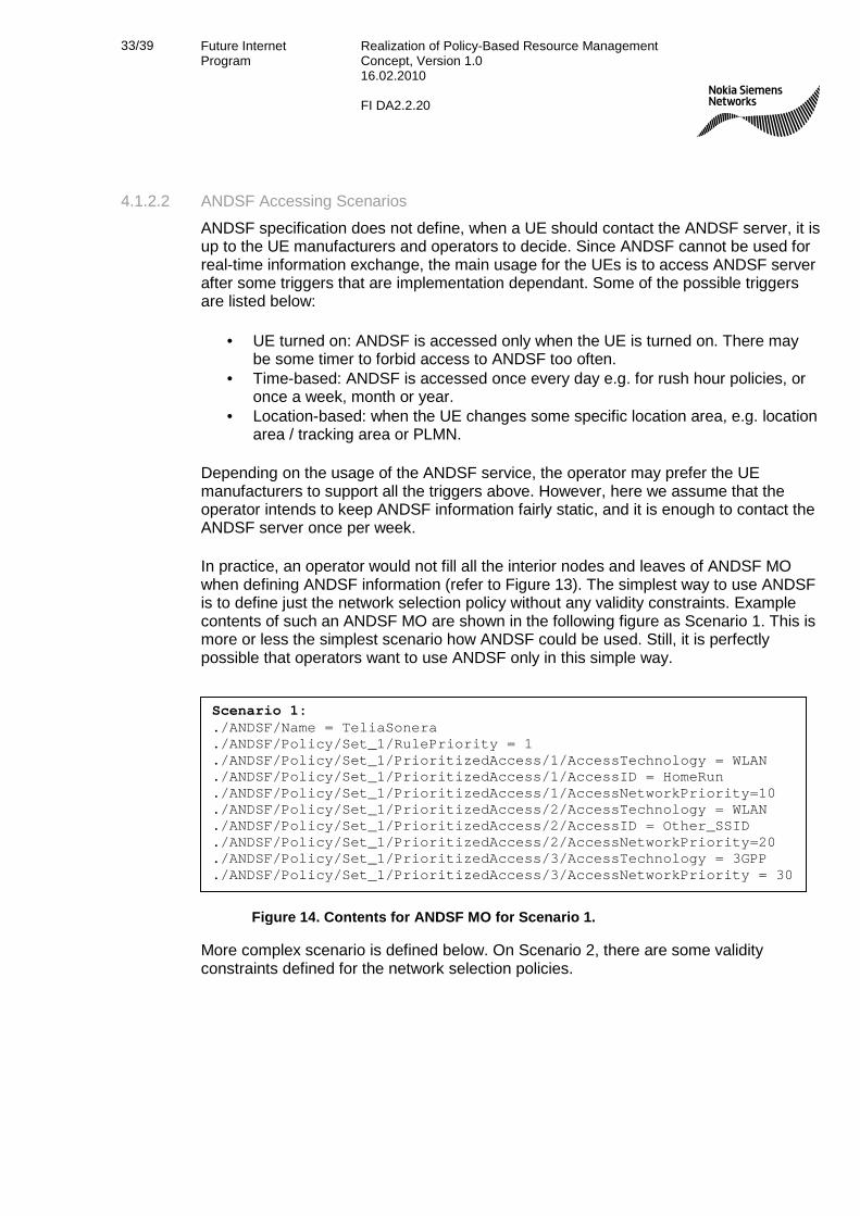
In practice, an operator would not fill all the interior nodes and leaves of ANDSF MO when defining ANDSF information (refer to Figure 13). The simplest way to use ANDSF is to define just the network selection policy without any validity constraints. Example contents of such an ANDSF MO are shown in the following figure as Scenario 1. This is more or less the simplest scenario how ANDSF could be used. Still, it is perfectly possible that operators want to use ANDSF only in this simple way.
More complex scenario is defined below. On Scenario 2, there are some validity constraints defined for the network selection policies.
Scenario 1: ./ANDSF/Name = TeliaSonera ./ANDSF/Policy/Set_1/RulePriority = 1 ./ANDSF/Policy/Set_1/PrioritizedAccess/1/AccessTechnology = WLAN ./ANDSF/Policy/Set_1/PrioritizedAccess/1/AccessID = HomeRun ./ANDSF/Policy/Set_1/PrioritizedAccess/1/AccessNetworkPriority=10 ./ANDSF/Policy/Set_1/PrioritizedAccess/2/AccessTechnology = WLAN ./ANDSF/Policy/Set_1/PrioritizedAccess/2/AccessID = Other_SSID ./ANDSF/Policy/Set_1/PrioritizedAccess/2/AccessNetworkPriority=20 ./ANDSF/Policy/Set_1/PrioritizedAccess/3/AccessTechnology = 3GPP ./ANDSF/Policy/Set_1/PrioritizedAccess/3/AccessNetworkPriority = 30
Figure 14. Contents for ANDSF MO for Scenario 1.

34/39 Future Internet Program
Realization of Policy-Based Resource Management Concept, Version 1.0 16.02.2010 FI DA2.2.20
Figure 15. Contents for ANDSF MO for Scenario 2. To give some ballpark figures on how much signaling traffic is created by ANDSF, estimated calculations for both Scenarios are given below. The estimations are calculated by applying WBXML coding on the messages described above for both scenarios.
Scenario 1: When applying the message sequence from Figure 12 for ANDSF, the messages 2 and 5 can be considered to be the same as in DM management session example in chapter 4.1.1.3. Scenario 1 message contents represented in Figure 14 is substituted into message 3 in Figure 12 as ANDSF data management message. The estimated size of message 3 in this scenario is around 1 600 bytes. Correspondingly, the message 4 contains the responses for the data management commands from message 3. The UE inserts a bit more data into the response message 4 than originally received in the message 3, around 2 100 bytes for that. Thus, the estimated amount of transferred bytes is:
1. Message 2, Alert: ~ 1 000 bytes 2. Message 3, ANDSF data management: ~ 1 600 bytes 3. Message 4, UE responses to msg#3 commands: ~ 2 100 bytes 4. Message 5, Status of msg#4: ~ 250 bytes
Overall, the transferred amount of bytes is circa 4 950 bytes in this scenario. Monthly data transfer with once a week ANDSF information download equals to 19 800 bytes (4 * 4 950 bytes).
Scenario 2: ./ANDSF/Name = TeliaSonera ./ANDSF/Policy/Set_1/RulePriority = 1 ./ANDSF/Policy/Set_1/PrioritizedAccess/1/AccessTechnology = WLAN ./ANDSF/Policy/Set_1/PrioritizedAccess/1/AccessID = HomeRun ./ANDSF/Policy/Set_1/PrioritizedAccess/1/AccessNetworkPriority=10 ./ANDSF/Policy/Set_1/PrioritizedAccess/2/AccessTechnology = WLAN ./ANDSF/Policy/Set_1/PrioritizedAccess/2/AccessID = Other_SSID ./ANDSF/Policy/Set_1/PrioritizedAccess/2/AccessNetworkPriority=20 ./ANDSF/Policy/Set_1/PrioritizedAccess/3/AccessTechnology = 3GPP ./ANDSF/Policy/Set_1/PrioritizedAccess/3/AccessNetworkPriority = 30 ./ANDSF/Policy/Set_1/ValidityArea/3GPP_Location/1/LAC = 15 ./ANDSF/Policy/Set_1/ValidityArea/3GPP_Location/2/LAC = 30 ./ANDSF/Policy/Set_1/TimeOfDay/1/TimeStart = 0800 ./ANDSF/Policy/Set_1/TimeOfDay/1/TimeStop = 1000 ./ANDSF/Policy/Set_1/TimeOfDay/2/TimeStart = 1600 ./ANDSF/Policy/Set_1/TimeOfDay/2/TimeStop = 1900 ./ANDSF/Policy/Set_2/RulePriority = 2 ./ANDSF/Policy/Set_2/PrioritizedAccess/1/AccessTechnology = WLAN ./ANDSF/Policy/Set_2/PrioritizedAccess/1/AccessID = HomeRun ./ANDSF/Policy/Set_2/PrioritizedAccess/1/AccessNetworkPriority=10 ./ANDSF/Policy/Set_2/PrioritizedAccess/2/AccessTechnology = 3GPP ./ANDSF/Policy/Set_2/PrioritizedAccess/2/AccessNetworkPriority = 30 ./ANDSF/Policy/Set_2/ValidityArea/3GPP_Location/1/PLMN = 24433

35/39 Future Internet Program
Realization of Policy-Based Resource Management Concept, Version 1.0 16.02.2010 FI DA2.2.20
Scenario 2: Here, ANDSF data management message 3 is a bit larger, the estimated size is around 3 200 bytes. Correspondingly, UE response message 4 is equally larger, around 3 700 bytes. Thus, in this scenario the estimated sizes of the messages are:
1. Message 2, Alert: ~ 1 000 bytes 2. Message 3, ANDSF data management: ~ 3 200 bytes 3. Message 4, UE responses to msg#3 commands: ~ 3 700 bytes 4. Message 5, Status of msg#4: ~ 250 bytes
The sum of messages is circa 8 150 bytes. Monthly data transfer with once a week ANDSF information download equals to 32 600 bytes (4 * 8 150 bytes).
As can be seen from the two scenarios above, the amount of total transferred bytes per ANDSF session increases quickly when more information is stored into ANDSF MO in the server. When comparing the monthly transferred bytes to e.g. size of current typical web page, the amounts are fairly small. But if ANDSF information is regarded as signaling traffic – as ANDSF information should be – then 32 600 bytes per month is not a small figure anymore.
The above scenarios are just general examples that cannot give exact numbers of ANDSF signaling. However, what can be seen from figures is that an operator planning to take ANDSF into use should carefully consider both the amount of data stored into ANDSF MO and how often and with what scheme UEs are expected to access the server. These two are the most significant factors influencing the ANDSF total signaling load.
4.2 MIH Signaling As a comparison for the ANDSF figures above, also corresponding MIIS signaling is considered in this chapter.
4.2.1 MIIS Message Exchange Just like ANDSF, also MIIS provides information request and response messages. In the request message, the UE may give a number of parameters to indicate what information UE is expecting to get from the MIIS server. Also, it is possible to indicate the UE’s location to the server e.g. with GPS coordinates or 3GPP cell identifier. UE may also define a geographical area (e.g. circle) from which the UE wishes to get information about different available networks.
MIIS defines several Infomration Elements (IE) that can be included in the information response message from the server. The IEs are grouped into network and AP/base station level information. If the server provides information about more than one network (or AP/base station), the information is prioritized by ordering the given list of network information. Unlike with ANDSF, it is not possible to define any validity constraints for network selection information in MIIS. This means the information MIIS provides is considered to be valid all the time, thus giving less flexibility for the operator to define the network selection information provided from the server.

36/39 Future Internet Program
Realization of Policy-Based Resource Management Concept, Version 1.0 16.02.2010 FI DA2.2.20
MIIS provides two different schemes to represent data in MIIS information request/response messages: XML and binary formats. When using binary format, the IEs are encoded using traditional Type Length Value (TLV) scheme. In this discussion, the binary format with TLV encoding is assumed.
4.2.2 MIIS Signaling Load MIH standard does not define a specific MIIS information procedure that should be followed when contacting MIIS server. For example, UE may first send MIH Capability Discover Request message, and/or MIH Register Request to MIIS server. According to the specification, it is also possible just send the MIH Get Information Request directly to the MIIS server, if the UE knows the address of the server and that the server provides MIIS services. Here, we assume only MIH Get Information Request and Responses are exchanged between the UE and server.
In the example MIH messages, the MIHF IDs fields are in 3GPP format, i.e. MIIS server MIHF ID is MIH.MNC012.MCC345.PUB.3GPPNETWORK.ORG and UE MIHF ID is [email protected].
When considering the Scenarios 1 and 2 from chapter 4.1.2.2 above, the following calculations on MIIS message sizes can be made (lower layer information not counted):
Scenario 1: The MIIS server provides a simple prioritized network list for the UE containing information from Figure 14:
1. MIH Get Information Request message: no optional fields are included in the message. The size of the MIHF message with above MIHF ID information is 88 bytes.
2. MIH Get Information Response message: the size of the message with the information described in Figure 14 is 299 bytes.
Scenario 2: The information shown in Figure 15 cannot fully be represented with MIIS: it is not possible to define two different lists of networks with MIIS, it is only possible to have one global network list that contains all the networks. Further, as mentioned earlier, it is not possible to define validity constraints in MIIS information (ValidityArea and TimeOfDay in Figure 15). Thus, it is not possible to give corresponding MIH message sizes for this scenario.
4.3 Summary Although no corresponding figures can be given for scenario 2 for MIIS server, it can clearly be seen from scenario 1 that MIH signaling consumes considerably less radio capacity than ANDSF signaling. In the example calculations above, ANDSF signaling created about 20 times more traffic on radio interface than MIIS. However, implementation of the message handling – especially on the UE side – has a considerable impact on the total time spent on management sessions. Thus, even if MIIS signaling is much more light-weight, it is not necessarily considerably faster to complete information provisioning with MIIS than with ANDSF.

37/39 Future Internet Program
Realization of Policy-Based Resource Management Concept, Version 1.0 16.02.2010 FI DA2.2.20
When comparing information provided by ANDSF and MIIS servers, it is interesting to note that MIIS server can offer wider range of information from a given network or AP/base station than ANDSF. However, from the operator point of view, with ANDSF it is possible to define more sophisticated network selection policies than with MIH, e.g. policies that are valid in certain geographical area, policies that are valid during specific time of day, etc. In summary, one could say MIH provides fewer options for defining network selection policies but more information for network discovery. Which one is better, depends on the usage: for the operator, ANDSF provides more versatile means to influence the network selection of the UEs.
38/39 Future Internet Program
Realization of Policy-Based Resource Management Concept, Version 1.0 16.02.2010 FI DA2.2.20
5. References [1] Policy-Based Resource Management, Future Internet Program deliverable 2.4.1,
version 1.0, 19.12.2008.
[2] Network Selection Simulations, Future Internet Program deliverable 2.4.3, version 1.0, 31.5.2009.
[3] Automated PBRM Server Configuration, Future Internet Program deliverable 2.4.2, version 1.0, 26.6.2009.
[4] Service Based Access Selection with PBRM, Future Internet Program deliverable 2.2.21, version 1.0, 4.6.2009.
[5] 3GPP TS 23.402, Architecture enhancements for non-3GPP accesses, Release 9, v9.2.0, September 2009.
[6] 3GPP TS 24.302, Access to the 3GPP Evolved Packet Core (EPC) via non-3GPP access networks, Release 9, v9.0.0, September 2009.
[7] 3GPP TS 24.312, Access Network Discovery and Selection Function (ANDSF) Management Object (MO), Release 8, v8.3.0, September 2009.
[8] IEEE Standard for Local and metropolitan area networks — Part 21: Media Independent Handover Services, 21 January 2009.
[9] LTE for UMTS, OFDMA and SC-FDMA Based Radio Access, Harri Holma and Antti Toskala, John Wiley & Sons Ltd., 2009.
[10] SAE and the Evolved Packet Core, Driving the Mobile Broadband Revolution, Magnus Olsson, Shabnam Sultana, Stefan Rommer, Lards Frid, Catherine Mulligan, Academic Press, 2009.
[11] IEEE P802.21 Tutorial, http://www.ieee802.org/21/Tutorials/802%2021-IEEE-Tutorial.ppt, Vivek Gupta, July 17 2006.
[12] IEEE P802.11u™/D8.0, Draft STANDARD for Information Technology—Telecommunications and information exchange between systems—Local and metropolitan area networks—Specific requirements Part 11: Wireless LAN Medium Access Control (MAC) and Physical Layer (PHY) specifications Amendment 7: Interworking with External Networks, July 2009.
[13] IEEE Std 802.16™-2009, IEEE Standard for Local and metropolitan area networks Part 16: Air Interface for Broadband Wireless Access Systems, 29 May 2009.
[14] 3GPP TS 33.220, Generic Authentication Architecture (GAA); Generic bootstrapping architecture, Release 9, v9.0.0, June 2009.

39/39 Future Internet Program
Realization of Policy-Based Resource Management Concept, Version 1.0 16.02.2010 FI DA2.2.20
[15] 3GPP TS 33.222, Generic Authentication Architecture (GAA); Access to network application functions using Hypertext Transfer Protocol over Transport Layer Security (HTTPS), Release 8, v8.0.0, June 2008.
[16] IEEE 802.21a working group document repository, https://mentor.ieee.org/802.21/documents.
[17] 3GPP TR 22.985, Service requirement for the User Data Convergence (UDC), Release 9, v9.0.0, December 2008.
[18] 3GPP TS 23.335, User Data Convergence; Technical Realization and Information Flows; Stage 2, Release 9, v.0.5.0, October 2009.
[19] 3GPP TS 23.203, Policy and charging control architecture, Release 9, v9.3.0, December 2009.
[20] 3GPP TS 23.261, IP Flow Mobility and seamless WLAN offload, Release 10, v0.1.0, December 2009.
[21] Enabler Release Definition for OMA Device Management, Approved Version 1.2 – 09 Feb 2007, OMA-ERELD-DM-V1_2-20070209-A.
[22] 3GPP TS 24.109, Bootstrapping interface (Ub) and network application function interface (Ua); Protocol details, v8.2.0, June 2009.
6. Acknowledgements This work was supported by TEKES as part of the Future Internet program of TIVIT (Finnish Strategic Centre for Science, Technology and Innovation in the field of ICT).