realtime tracking meets online grasp planning
TRANSCRIPT

RealTime Tracking Meets Online Grasp Planning
Danica Kragic, Andrew T. Miller and Peter K. Allen
Computer Vision and Active Perception Department of Computer ScienceNumerical Analysis and Computer Science Columbia University
Royal Institute of Technology New York, NY 10027 ∗
SE–100 44 Stockholm, Sweden †
Abstract
This paper describes a synergistic integration of agrasping simulator and a real-time visual tracking sys-tem, that work in concert to 1) find an object’s pose, 2)plan grasps and movement trajectories, and 3) visuallymonitor task execution. Starting with a CAD model ofan object to be grasped, the system can find the object’spose through vision which then synchronizes the stateof the robot workcell with an online, model-based graspplanning and visualization system we have developedcalled GraspIt. GraspIt can then plan a stable graspfor the object, and direct the robotic hand system toperform the grasp. It can also generate trajectories forthe movement of the grasped object, which are used bythe visual control system to monitor the task and com-pare the actual grasp and trajectory with the plannedones. We present experimental results using typicalgrasping tasks.
1 Introduction
Visual control of robotic tasks is a major goal of cur-rent robotics research. The advent of real-time vi-sion systems has led to the creation of systems thatuse cameras to control robotic tasks such as grasping[13]. This paper describes a system that extends thisparadigm in a number of ways. Most importantly, wehave been able to integrate real-time vision with on-line, model-based simulation, to create a grasp plan-ning, control and monitoring system that can visuallydetermine an object’s pose, plan a stable grasp, ex-ecute the grasp, and monitor the task for errors andcorrectness (see Fig. 1). The vision system is respon-
∗This work was supported in part by an ONR/DARPAMURI award ONR N00014-95-1-0601 and NSF grant CDA-96-25374. We would also like to thank Professor Gerd Hirzingerand Dr. Max Fischer from the German Aerospace Center (DLR)for providing us with models of their robotic hand.
†This research has been sponsored by the Swedish Founda-tion for Strategic Research through the Centre for AutonomousSystems. The funding is gratefully acknowledged.
sible for providing accurate and fast estimates of anobject’s pose, while the grasping simulator uses theseestimates to plan 1) an effective and stable grasp ofthe object and 2) a collision free trajectory in theworkspace for transporting the grasped object to anew position. The simulator output is then used toexecute the planned grasp and trajectory, which ismonitored by the vision system.
EXECUTION
GRASP
PUMA 560
MONITORING
TASK
OBJECT POSE
ESTIMATION
PLANNINGGRASPGraspIt!
Robot/Hand
Frame
Control
Grabber
Figure 1: Block diagram of the system.
By merging visual control with grasp planning, wehave created a system that can extend the idea of au-tonomous robot control. Using a calibrated vision sys-tem, we only need a CAD model of the object to begrasped to both track the object and determine itspose in real-time. The grasping simulator, previouslydeveloped by Miller and Allen [9, 10], is able to com-pute a stable grasp with a quality measure in real-timeusing the same CAD model. The grasp stability analy-sis also includes material properties of the object, andthe simulator contains a library of robots and hands tochoose from, giving it added flexibility for use in manydifferent robot workcells. Below, we describe the vi-sion and grasp simulation modules, and then discussthe integration of these modules on real grasping tasksusing a Barrett hand.
2 Pose Estimation and Tracking
Closed-loop control of a robot where vision is used inthe feedback loop is commonly referred to as visualservoing, [7]. Vision based tracking techniques incor-porated in visual servoing systems usually facilitatemodel based or feature based approaches. A modelbased approach relies on a CAD model of the objectto be tracked [3, 12] while feature based techniquesuse distinct image features: corners, lines, regions [6].There are two categories of visual servoing: positionbased servoing and image based servoing, [7]. In ourwork, we use both approaches: position based ap-proach is used for driving the arm and the hand toa pose generated by a simulator. Later, image basedservo control is used to visually servo a grasped objectto the desired pose.
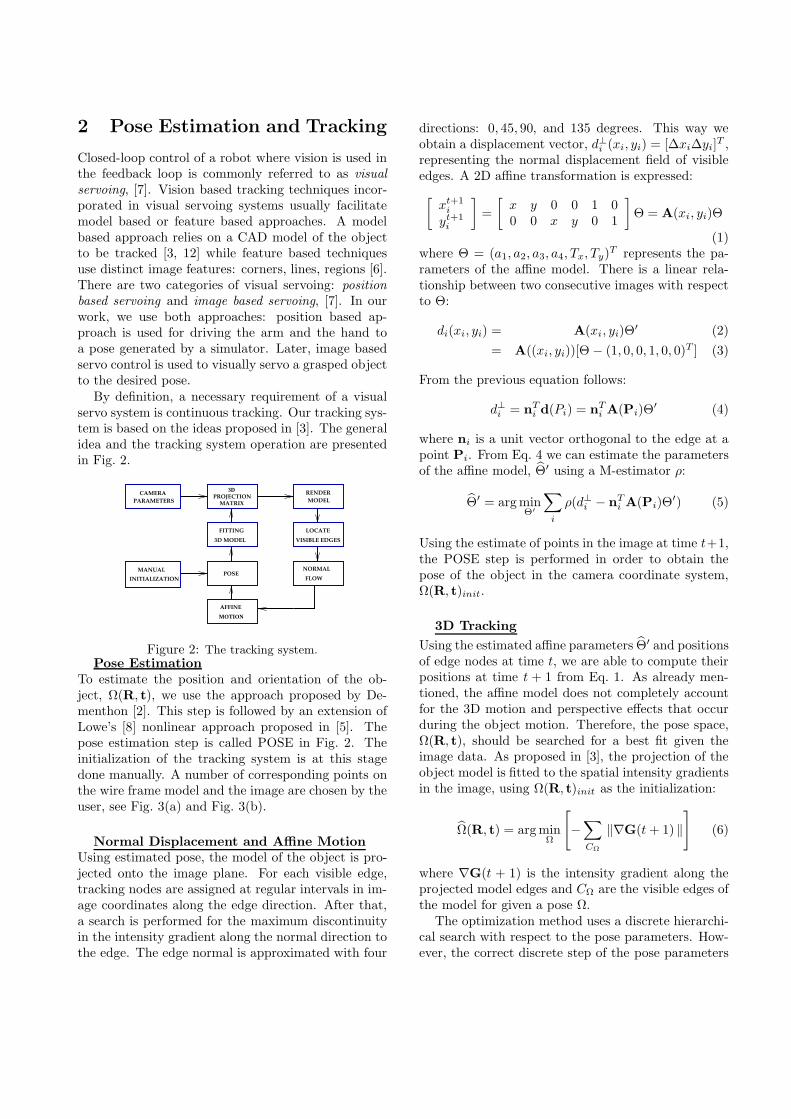
By definition, a necessary requirement of a visualservo system is continuous tracking. Our tracking sys-tem is based on the ideas proposed in [3]. The generalidea and the tracking system operation are presentedin Fig. 2.
FITTING
MOTION
POSEINITIALIZATION
MANUAL
PARAMETERSCAMERA
MATRIX
3D MODEL VISIBLE EDGES
FLOW
NORMAL
AFFINE
LOCATE
RENDER MODEL
3DPROJECTION
Figure 2: The tracking system.Pose Estimation
To estimate the position and orientation of the ob-ject, Ω(R, t), we use the approach proposed by De-menthon [2]. This step is followed by an extension ofLowe’s [8] nonlinear approach proposed in [5]. Thepose estimation step is called POSE in Fig. 2. Theinitialization of the tracking system is at this stagedone manually. A number of corresponding points onthe wire frame model and the image are chosen by theuser, see Fig. 3(a) and Fig. 3(b).
Normal Displacement and Affine Motion
Using estimated pose, the model of the object is pro-jected onto the image plane. For each visible edge,tracking nodes are assigned at regular intervals in im-age coordinates along the edge direction. After that,a search is performed for the maximum discontinuityin the intensity gradient along the normal direction tothe edge. The edge normal is approximated with four
directions: 0, 45, 90, and 135 degrees. This way weobtain a displacement vector, d⊥
i (xi, yi) = [∆xi∆yi]T ,
representing the normal displacement field of visibleedges. A 2D affine transformation is expressed:
[xt+1
i
yt+1i
]=
[x y 0 0 1 00 0 x y 0 1
]Θ = A(xi, yi)Θ
(1)where Θ = (a1, a2, a3, a4, Tx, Ty)T represents the pa-rameters of the affine model. There is a linear rela-tionship between two consecutive images with respectto Θ:
di(xi, yi) = A(xi, yi)Θ′ (2)
= A((xi, yi))[Θ − (1, 0, 0, 1, 0, 0)T ] (3)
From the previous equation follows:
d⊥i = nTi d(Pi) = nT
i A(Pi)Θ′ (4)
where ni is a unit vector orthogonal to the edge at apoint Pi. From Eq. 4 we can estimate the parametersof the affine model, Θ′ using a M-estimator ρ:
Θ′ = arg minΘ′
∑
i
ρ(d⊥i − nTi A(Pi)Θ
′) (5)
Using the estimate of points in the image at time t+1,the POSE step is performed in order to obtain thepose of the object in the camera coordinate system,Ω(R, t)init.
3D Tracking
Using the estimated affine parameters Θ′ and positionsof edge nodes at time t, we are able to compute theirpositions at time t + 1 from Eq. 1. As already men-tioned, the affine model does not completely accountfor the 3D motion and perspective effects that occurduring the object motion. Therefore, the pose space,Ω(R, t), should be searched for a best fit given theimage data. As proposed in [3], the projection of theobject model is fitted to the spatial intensity gradientsin the image, using Ω(R, t)init as the initialization:
Ω(R, t) = arg minΩ
[−
∑
CΩ
‖∇G(t + 1) ‖
](6)
where ∇G(t + 1) is the intensity gradient along theprojected model edges and CΩ are the visible edges ofthe model for given a pose Ω.
The optimization method uses a discrete hierarchi-cal search with respect to the pose parameters. How-ever, the correct discrete step of the pose parameters
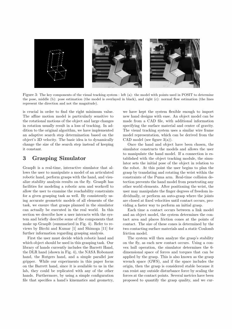
Figure 3: The key components of the visual tracking system : left (a): the model with points used in POSIT to determinethe pose, middle (b): pose estimation (the model is overlayed in black), and right (c): normal flow estimation (the linesrepresent the direction and not the magnitude).
is crucial in order to find the right minimum value.The affine motion model is particularly sensitive tothe rotational motions of the object and large changesin rotation usually result in a loss of tracking. In ad-dition to the original algorithm, we have implementedan adaptive search step determination based on theobject’s 3D velocity. The basic idea is to dynamicallychange the size of the search step instead of keepingit constant.
3 Grasping Simulator
GraspIt is a real-time, interactive simulator that al-lows the user to manipulate a model of an articulatedrobotic hand, perform grasps with the hand, and visu-alize stability analysis results on the fly. GraspIt hasfacilities for modeling a robotic arm and workcell toallow the user to examine the reachability constraintsfor a given grasping task as well. By consistently us-ing accurate geometric models of all elements of thetask, we ensure that grasps planned in the simulatorcan actually be executed in the real world. In thissection we describe how a user interacts with the sys-tem and briefly describe some of the components thatmake up GraspIt (summarized in Fig. 4). Refer to re-views by Bicchi and Kumar [1] and Shimoga [11] forfurther information regarding grasping analysis.
First the user must decide which robotic hand andwhich object should be used in this grasping task. Ourlibrary of hands currently includes the Barrett Hand,the DLR hand (shown in Fig. 4), the NASA Robonauthand, the Rutgers hand, and a simple parallel jawgripper. While our experiments in this paper focuson the Barrett hand, since it is available to us in thelab, they could be replicated with any of the otherhands. Furthermore, by using a simple configurationfile that specifies a hand’s kinematics and geometry,
we have kept the system flexible enough to importnew hand designs with ease. An object model can bemade from a CAD file, with additional informationspecifying the surface material and center of gravity.The visual tracking system uses a similar wire framemodel representation, which can be derived from theCAD model (see figure 3(a)).
Once the hand and object have been chosen, thesimulator constructs the models and allows the userto manipulate the hand model. If a connection is es-tablished with the object tracking module, the simu-lator sets the initial pose of the object in relation tothe robot. At this point the user begins to plan thegrasp by translating and rotating the wrist within theconstraints of the Puma arm. Real-time collision de-tection prevents the hand model from penetrating anyother world elements. After positioning the wrist, theuser may manipulate the finger degrees of freedom in-dividually, or perform an auto-grasp where the jointsare closed at fixed velocities until contact occurs, pro-viding a faster way to perform an initial grasp.
Each time a contact occurs between a link modeland an object model, the system determines the con-tact area and places friction cones at the points ofcontact. The size of these cones is determined by thetwo contacting surface materials and a static Coulombfriction model.
The system will then analyze the grasp’s stabilityon the fly, as each new contact occurs. Using a con-vex hull operation, the simulator determines the 6-dimensional space of forces and torques that can beapplied by the grasp. This is also known as the graspwrench space (GWS), and if the space includes theorigin, then the grasp is considered stable because itcan resist any outside disturbance force by scaling theforces at the contact points. Several metrics have beenproposed to quantify the grasp quality, and we cur-

Quality
Computation
compute grasp
ContactDetermination
detect collisionsadjust contact toobject surfacefind contact areaadd friction cone(s)
wrench space
GraspIt!
find min facetdistancefind hull volume
UserInterface
view 3D scenechange hand pose
ConstructionHand/Object
read object modelread link modelsread kinematicsassemble hand
auto−grip
project facets toforce space andto torque spaceintersect both setsof halfspaces
Visualization
manually movejoints
Wrench Space
Figure 4: (Left) The internal components of GraspIt! and their functions. (Right) The DLR hand grasping a flask. Thevolumes in the small windows are projections of the grasp wrench space for this grasp.
rently compute two of them, although others couldeasily be added. The first is a worst case measure ofthe grasp’s weakest point, and is defined by the dis-tance from the origin to the closest facet on the bound-ary of the grasp wrench space. Indicators within thescene also show the direction of the worst case distur-bance force and torque, and aid the user in finding thisweakest point. The second measure is defined by thevolume of the GWS and serves as more of an averagecase quality measure.
In addition to the numeric measures, the user isalso presented with various 3-dimensional projectionsof the GWS to allow better visualization of a grasp’sstrong and weak points. This information allows theuser to incrementally improve the stability of thegrasp, and once satisfied, the user may chose to ex-ecute the grasp with an actual robotic hand.
4 Experimental Evaluation
To test the system we set up some simple graspingtasks using two different objects. The task involveddetermining the object’s pose from vision, finding anappropriate and stable grasp for the robotic handgiven the object’s configuration, executing the grasp,and monitoring the grasped object’s trajectory as itmoved.
The dextrous robot hand used in this example is theBarret Hand. The details about the hand can be foundin [9]. The hand is attached to a Puma560 arm whichoperates in a simple workcell. The vision system usesa standard CCD camera (Sony XC-77) with a focallength of 25mm and is calibrated with respect to therobot workspace. The camera is mounted on a tripodand views the robot and workcell from a 2m distance.Both the robot controller and the framegrabber areconnected to a Sparc20 workstation which is linked via
a TCP socket connection to an SGI Indigo 2 runningthe GraspIt software.
The process of planning and executing a graspingtask is as follows (refer also to the block diagram pre-sented in Fig. 1):
1. After an image of the scene is obtained, interac-tive pose estimation of the object is performed aspresented in Section 2.
2. A pose estimate is sent to the GraspIt graspplanning software which assists a user to generatethe most suitable grasp.
3. Through GraspIt the actual arm and hand arecontrolled in order to perform the final grasp.
4. Once the object is grasped, the monitoring taskbegins. Image based visual servoing is usedto place the object into the final desired pose.Through GraspIt, a few trajectory points (ob-ject poses) are manually generated. Each gener-ated pose is used as an intermediate desired posefor the visual servoing routine.
Our two example grasps (Fig. 5) demonstrate steps1-3 of the system (pose estimation, grasp planning andgrasp execution). After the first image of the sceneis acquired, a manual initialization step is performedas explained in Section 2, and the estimated pose ofthe object is sent to GraspIt, which aids the user inselecting an appropriate grasp. After a satisfactorygrasp is planned, it is executed by controlling boththe robot arm and the robot hand.
The first example shows a successfully planned andexecuted stable grasp of an L-shaped object. Thegrasp planned in the second example is not stable butrequires precise estimation of the object pose so thatthe thumb can hook through the handle of the mug
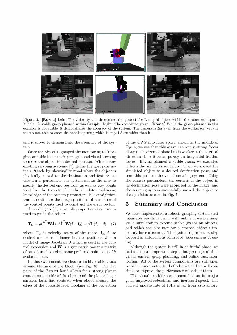
Figure 5: [Row 1] Left: The vision system determines the pose of the L-shaped object within the robot workspace.Middle: A stable grasp planned within GraspIt. Right: The completed grasp. [Row 2] While the grasp planned in thisexample is not stable, it demonstrates the accuracy of the system. The camera is 2m away from the workspace, yet thethumb was able to enter the handle opening which is only 1.5 cm wider than it.
and it serves to demonstrate the accuracy of the sys-tem.
Once the object is grasped the monitoring task be-gins, and this is done using image based visual servoingto move the object to a desired position. While manyexisting servoing systems, [7], define the goal pose us-ing a “teach–by–showing” method where the object isphysically moved to the destination and feature ex-traction is performed, our system allows the user tospecify the desired end position (as well as way pointsto define the trajectory) in the simulator and usingknowledge of the camera parameters, it is straightfor-ward to estimate the image positions of a number ofthe control points used to construct the error vector.
According to [7], a simple proportional control isused to guide the robot:
TG = g(JTWJ)−1J
TW(f − fd) = gJ
†(fd − f) (7)
where TG is velocity screw of the robot, fd, f aredesired and current image features positions, J is amodel of image Jacobian, J which is used in the con-trol expression and W is a symmetric positive matrixof rank 6 used to select some preferred points out of k
available ones.In this experiment we chose a highly stable grasp
around the side of the block, (see Fig. 6). The flatpalm of the Barrett hand allows for a strong planarcontact on one side of the object and the planar fingersurfaces form line contacts when closed around theedges of the opposite face. Looking at the projection
of the GWS into force space, shown in the middle ofFig. 6, we see that this grasp can apply strong forcesalong the horizontal plane but is weaker in the verticaldirection since it relies purely on tangential frictionforces. Having planned a stable grasp, we executedit from the simulator as before. Then we moved thesimulated object to a desired destination pose, andsent this pose to the visual servoing system. Usingthe camera parameters, the corners of the object inits destination pose were projected to the image, andthe servoing system successfully moved the object tothat position as seen in Fig. 7.
5 Summary and Conclusion
We have implemented a robotic grasping system thatintegrates real-time vision with online grasp planningvia a simulator to execute stable grasps on objects,and which can also monitor a grasped object’s tra-jectory for correctness. The system represents a stepforward in autonomous control of tasks such as grasp-ing.
Although the system is still in an initial phase, webelieve it is an important step in integrating real-timevisual control, grasp planning, and online task mon-itoring. All of the system components are still openresearch issues in the field of robotics and we will con-tinue to improve the performance of each of them.
The visual tracking component has as its majorgoals improved robustness and increased speed. Thecurrent update rate of 10Hz is far from satisfactory.

Figure 6: (Left) A stable grasp of the L-shaped object. The axes are positioned at the object’s center of gravity (Z axispoints into the table). (Middle Top) The 6D grasp wrench space projected into torque space by setting the net force to0. (Z axis points up). (Middle Bottom) The GWS projected into force space by setting the net torque to 0. (Right) Thetask is planned in GraspIt by moving the object from its original location (empty wireframe) to its destination point andsaving the new object pose.
Figure 7: Snapshots of the servoing near the beginningand end of the task. The object is being tracked and thecorners of the destination pose are shown as white dots inthe image.
To improve the robustness in the case of significantocclusions and natural background, we will continueto test the two implemented tracking techniques moreextensively. In addition, none of the techniques incor-porates any kind of velocity or acceleration predictionwhich can be easily added (e.g. a Kalman filter ap-proach).
Currently, the grasp planning function is only semi-automated; the user needs to place the hand in prox-imity of the object and an automated finger contactprocedure is instituted. We are exploring adding rulesto properly synthesize a grasp given an object’s poseand environmental constraints [4].
References
[1] A. Bicchi and V. Kumar. Robotic grasping and contact: Areview. In Proc. of the IEEE Int. Conf. on Robotics and
Automation, pages 348–353, 2000.
[2] D.Dementhon and L. S. Davis. Model–based object posein 25 lines of code. International Journal of Computer
Vision, 15:123–141, 1995.
[3] P. E.Marchand and F.Chaumette. A 2D–3D model–basedapproach to real–time visual tracking. Technical report,INRIA, March, 2000.
[4] K. Goldberg, E. Smith, K. Bohringer, and J. Craig. Com-puting parallel-jaw grip points. In Proc of the IEEE Int.
Conf. on Robotics and Automation, 1999.
[5] R. L. C. H. Araujo and C. Brown. A fully projective formu-lation for Lowe’s tracking algorithm. Technical report 641,The University of Rochester, CS Department, Rochester,NY, November, 1996.
[6] G. Hager and K. Toyama. The XVision system: Ageneral-purpose substrate for portable real–time vision ap-plications. Computer Vision and Image Understanding,1(69):22–37.
[7] S. Hutchinson, G. D. Hager, and P. I. Corke. A tutorial onvisual servo control. IEEE Transactions on Robotics and
Automation, 12(5):651–670, 1996.
[8] D. G. Lowe. Robust model–based motion tracking throughthe integration of search and estimation. International
Journal of Computer Vision, 8(2):113–122, 1992.
[9] A. Miller and P. Allen. Examples of 3D grasp quality com-putations. In Proc. of the IEEE Int. Conf. on Robotics
and Automation, pages 1240–1246, 1999.
[10] A. Miller and P. Allen. GraspIt!: A versatile simulator forgrasping analysis. In S. Nair, editor, Proc. of the ASME
Dynamic Systems and Control Division, 2000.
[11] K. B. Shimoga. Robot grasp synthesis algorithms: Asurvey. International Journal of Robotics Research,15(3):230–266, June 1996.
[12] P. Wunsch and G.Hirzinger. Real–time visual tracking of3D objects with dynamic handling of occlusion. In Proc. of
the IEEE Int. Conf. on Robotics and Automation, pages2868–2872, 1997.
[13] B. Yoshimi and P. Allen. Visual control of grasping. InD. Kriegman, G. Hager, and S. Morse, editors, The Con-
fluence of Vision and Control, pages 195–209. Springer-Verlag, 1998.