rebuilding surfaces in a corrupt model with creo … surfaces in a corrupt model with creo elements...
TRANSCRIPT

rebuilding surfaces in a corrupt Model with creo eleMents direct By Ian Campbell, ME
Figure 1 Creo returned an error
message to a command removing the red chamfer in this case part.
Andrews-Cooper routinely works with models that are not native to Creo Elements Direct, geometries imported from industrial designers or downloaded from the web. When these files, typically in the .stp or .igs format, are loaded they may contain deficiencies due to translation issues that make them challenging to manipulate. In some cases these parts must be rebuilt from scratch (B-spline surfaces present the greatest challenge). This document provides step-by-step instructions and illustrates with an example how to repaire a complex surface and generating a robust part.
identify Often times the first clue that a surface should be rebuilt is when a relatively simple adjustment fails to calculate and the ‘cannot solve location operation’ message is displayed. Even a very small offset or draft command can fail if the underlying surface is not well suited for manipulation. In this part, an attempt to cut or align the red chamfer fails, signaling that the surface may have deficiencies.
untriM and extendOnce the offending surface is identified it is necessary to find which region, specifically, is causing the failure. This is accomplished by copying the surface of the solid and using the untrim command with an extension value greater than 1 on the newly created surface. In this example a 10% increase in size (i.e. an extension value of 1.1) exposed the problem area (lower left corner).
cross-sectionIn order to recreate a matching surface from scratch, some of the good data must be retrieved from the otherwise corrupt face. One approach is to create an array of workplanes and project 2D cross sections of the untrimmed surface. The spacing between workplanes will impact how closely the newly created surface will match the imported surface. Areas of high curvature should be more densely populated with workplanes to more accurately represent the imported surface. In this example, a relatively coarse and equal spacing was used with the final workplace adjusted slightly to avoid the folded area.
create a spineFrom these existing 2D geometries one could simply re-skin the part and create a new surface matching the original face. However, the cross-sections maintain the curvature data of the original part and the resulting sur-face will have the same anomaly in the lower left corner. One technique to force Creo to reconsider the calcula-tion of the surface is to create a spine perpendicular to the existing cross sections. This is accomplished by using the Split Edge command on each of the 2D lines, creating evenly spaced vertices, and then drawing a 3D
Figure 2 The right illustration shows the original surface and the surface extended by 10%. The left illustration is a zoom of the region exhibiting the irregular fold.
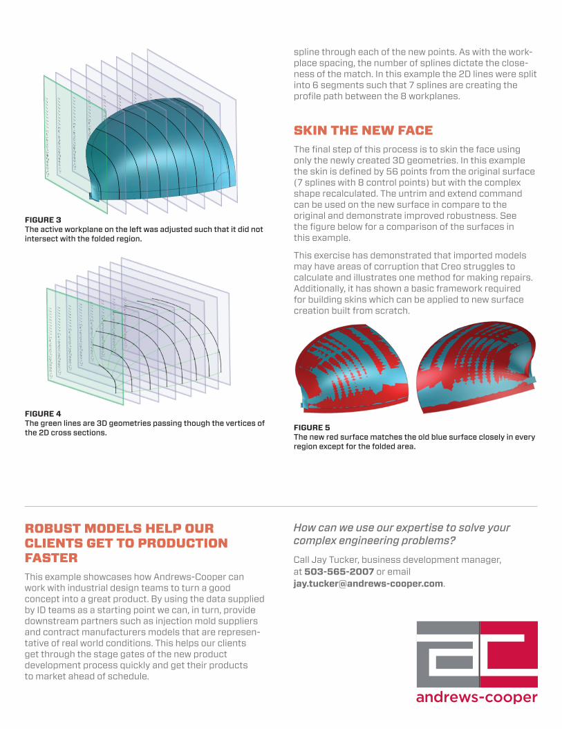
spline through each of the new points. As with the work-place spacing, the number of splines dictate the close-ness of the match. In this example the 2D lines were split into 6 segments such that 7 splines are creating the profile path between the 8 workplanes.
skin the new faceThe final step of this process is to skin the face using only the newly created 3D geometries. In this example the skin is defined by 56 points from the original surface (7 splines with 8 control points) but with the complex shape recalculated. The untrim and extend command can be used on the new surface in compare to the original and demonstrate improved robustness. See the figure below for a comparison of the surfaces in this example.
This exercise has demonstrated that imported models may have areas of corruption that Creo struggles to calculate and illustrates one method for making repairs. Additionally, it has shown a basic framework required for building skins which can be applied to new surface creation built from scratch.
Figure 4 The green lines are 3D geometries passing though the vertices of the 2D cross sections. Figure 5
The new red surface matches the old blue surface closely in every region except for the folded area.
Figure 3 The active workplane on the left was adjusted such that it did not intersect with the folded region.
How can we use our expertise to solve your complex engineering problems?
Call Jay Tucker, business development manager, at 503-565-2007 or email [email protected].
robust Models help our clients get to production fasterThis example showcases how Andrews-Cooper can work with industrial design teams to turn a good concept into a great product. By using the data supplied by ID teams as a starting point we can, in turn, provide downstream partners such as injection mold suppliers and contract manufacturers models that are represen-tative of real world conditions. This helps our clients get through the stage gates of the new product development process quickly and get their products to market ahead of schedule.