rec 670- operators manual
TRANSCRIPT
Innovation from ABB
Operator's manualBay control IEDREC 670


Document ID: 1MRK511188-UENIssued: December 2007
Revision: BIED product version: 1.1
© Copyright 2007 ABB. All rights reserved
COPYRIGHTWE RESERVE ALL RIGHTS TO THIS DOCUMENT, EVEN IN THE EVENTTHAT A PATENT IS ISSUED AND A DIFFERENT COMMERCIALPROPRIETARY RIGHT IS REGISTERED. IMPROPER USE, INPARTICULAR REPRODUCTION AND DISSEMINATION TO THIRDPARTIES, IS NOT PERMITTED.
THIS DOCUMENT HAS BEEN CAREFULLY CHECKED. HOWEVER, INCASE ANY ERRORS ARE DETECTED, THE READER IS KINDLYREQUESTED TO NOTIFY THE MANUFACTURER AT THE ADDRESSBELOW.
THE DATA CONTAINED IN THIS MANUAL IS INTENDED SOLELY FORTHE CONCEPT OR PRODUCT DESCRIPTION AND IS NOT TO BEDEEMED TO BE A STATEMENT OF GUARANTEED PROPERTIES. INTHE INTEREST OF OUR CUSTOMERS, WE CONSTANTLY SEEK TOENSURE THAT OUR PRODUCTS ARE DEVELOPED TO THE LATESTTECHNOLOGICAL STANDARDS. AS A RESULT, IT IS POSSIBLE THATTHERE MAY BE SOME DIFFERENCES BETWEEN THE HW/SWPRODUCT AND THIS INFORMATION PRODUCT.
Manufacturer:
ABB AB
Substation Automation Products
SE-721 59 Västerås
Sweden
Telephone: +46 (0) 21 34 20 00
Facsimile: +46 (0) 21 14 69 18
www.abb.com/substationautomation
Table of contents
Section 1 Introduction.....................................................................11Introduction to the operator’s manual...............................................11
About the complete set of manuals for an IED............................11About the operator’s manual.......................................................12Intended audience.......................................................................13Related documents......................................................................13Revision notes.............................................................................13
Section 2 Safety information..........................................................15Warnings..........................................................................................15
Section 3 Overview........................................................................17Operator overview............................................................................17Identify the IED.................................................................................17
Section 4 Understand the local human-machine interface.............19Overview...........................................................................................19Keypad.............................................................................................20Key activated screens......................................................................21
The Help screen..........................................................................21The Reset screen........................................................................21
LCD..................................................................................................22Small............................................................................................22Medium........................................................................................22
LED...................................................................................................22Status indication LEDs................................................................22Indication LEDs...........................................................................22
LHMI setup and test screen..............................................................23How to navigate................................................................................24
Read............................................................................................24Change .......................................................................................24Control.........................................................................................25
Section 5 Understand the HMI tree................................................27Overview...........................................................................................27
Menu-tree for REC 670...............................................................27
Section 6 Read measured values..................................................29Overview...........................................................................................29View analog primary values..............................................................30
Overview......................................................................................30
Table of contents
REC 670 Operator's manual1MRK511188-UEN rev. B
1
View analog secondary values.........................................................30Overview......................................................................................30
View analog mean values.................................................................30Overview......................................................................................30
mA input module (MIM)..........................................................30View monitoring values.....................................................................31
Service values.............................................................................31Current phasors...........................................................................31Voltage phasors...........................................................................31Current sequence component.....................................................31Voltage sequence component.....................................................32
View metering values.......................................................................32
Section 7 Event list.........................................................................33View events......................................................................................33
Overview......................................................................................33
Section 8 Handle disturbances.......................................................35Identify a disturbance.......................................................................35View disturbance record details........................................................35
View general information.............................................................35View disturbance indications.......................................................35View event recordings.................................................................35View trip values...........................................................................36Recalculate distance to fault........................................................36
Trigger a disturbance report manually..............................................36
Section 9 Read and change settings.............................................37System time and synchronization.....................................................37
System time.................................................................................37Time synchronization...................................................................37
Overview................................................................................37TimeSynch.............................................................................37TimeSynchBIN.......................................................................38TimeSynchSNTP....................................................................38TimeSynchDSTBegin.............................................................38TimeSynchDSTEnd................................................................38TimeZone...............................................................................38TimeSynch IRIG-B.................................................................38
General settings...............................................................................38Power system..............................................................................39
Overview................................................................................39Identifiers................................................................................39Primary values........................................................................39
Table of contents
2 Operator's manual1MRK511188-UEN rev. B
REC 670

Communication............................................................................39Overview................................................................................39TCP-IP ...................................................................................39SPA, LON and IEC 60870–5–103 settings.............................40LDCM.....................................................................................41Station communication...........................................................41
Analog modules...........................................................................42Overview................................................................................42Analog modules......................................................................42I/O modules............................................................................43
HMI..............................................................................................43Overview................................................................................43LEDs.......................................................................................43Screen ...................................................................................44Functions................................................................................44Change lock...........................................................................44
Control.........................................................................................44Overview................................................................................44Bay control (CBAY)................................................................44Reservation input ..................................................................44Bay reserve (CRSV)...............................................................45Switch controller (CSWI)........................................................45Circuit breaker (XCBR)...........................................................45Circuit switch (XSWI)..............................................................45Local/Remote switch (LocalRemote, LocRemControl)...........45
Control commands......................................................................45Single command.....................................................................45Logic rotating switch (GGIO)..................................................46Selector mini switch (GGIO)...................................................46Tap changer control and supervision (YLTC, 84) ..................46Tap changer control and supervision (YLTC, 84)...................46Automatic voltage control for tapchanger (ATCC, 90) ...........46Automatic voltage control for tapchanger (ATCC, 90) ...........46
Monitoring....................................................................................47Overview................................................................................47Measurements (MMXU).........................................................47Current phasors......................................................................47Voltage phasors.....................................................................47Current sequence components (MSQI)..................................47Voltage sequence components (MSQI).................................48Disturbance report (RDRE)....................................................48Binary signals.........................................................................48Analog signals........................................................................48
Table of contents
REC 670 Operator's manual1MRK511188-UEN rev. B
3
Fault locator (RFLO)...............................................................48Generic measured value........................................................48Event function.........................................................................49Local signal status report.......................................................49IEC 60870–5–103...................................................................49
Metering.......................................................................................49Overview................................................................................49Pulse counter logic (GGIO)....................................................49Function for energy calculation and demand handling(MMTR) .................................................................................49
Setting group N.................................................................................50Overview......................................................................................50Differential protection...................................................................50
Overview................................................................................50High impedance differential protection (PDIF, 87X)...............50
Impedance protection..................................................................50Overview................................................................................50
Current protection........................................................................51Overview................................................................................51Instantaneous phase overcurrent protection (PIOC, 50)........51Four step phase overcurrent protection (PTOC, 51/67).........51Instantaneous residual overcurrent protection (PIOC,50N)........................................................................................51Four step residual overcurrent protection (PTOC, 51N/67N)........................................................................................51Thermal overload protection, one time constant (PTTR,26) .........................................................................................52Thermal overload protection, two time constants (PTTR,49) .........................................................................................52Breaker failure protection (RBRF, 50BF)...............................52Stub protection (PTOC, 50STB).............................................52Pole discordance protection (RPLD, 52PD)...........................52Broken conductor check (PTOC, 46).....................................52Directional over-power protection (PDOP, 32).......................53Directional under-power protection (PDUP, 37).....................53Sensitive directional residual over current and powerprotection (PSDE, 67N) .........................................................53
Voltage protection........................................................................53Overview................................................................................53Two step undervoltage protection (PTUV, 27).......................53Two step overvoltage protection (PTOV, 59).........................53Two step residual overvoltage protection (PTOV, 59N).........54Loss of voltage check (PTUV 27)...........................................54Voltage differential protection (PTOV 60)...............................54
Table of contents
4 Operator's manual1MRK511188-UEN rev. B
REC 670
Frequency protection...................................................................54Overview................................................................................54Underfrequency protection (PTUF, 81)..................................54Overfrequency protection (PTOF, 81)....................................54Rate-of-change frequency protection (PFRC, 81)..................55
Multipurpose protection...............................................................55Overview................................................................................55General current and voltage protection (GAPC)....................55
Secondary system supervision....................................................55Overview................................................................................55Current circuit supervision (RDIF)..........................................55Fuse failure supervision (RFUF)............................................56
Control.........................................................................................56Overview................................................................................56Synchrocheck and energizing check (RSYN, 25)..................56Autorecloser (RREC, 79)........................................................56Logic rotating switch (GGIO)..................................................56Tap changer control and supervision, 6 binary inputs(YLTC, 84) .............................................................................57Tap changer control and supervision, 32 binary inputs(YLTC, 84) .............................................................................57Automatic voltage control for tapchanger, single control(ATCC, 90) ............................................................................57Automatic voltage control for tapchanger, parallel control(ATCC, 90) ............................................................................57
Scheme communication..............................................................57Overview................................................................................57Scheme communication logic for distance or overcurrentprotection (PSCH, 85) ...........................................................57Current reversal and weak-end infeed logic for distanceprotection (PSCH, 85)............................................................58Local acceleration logic (PLAL)..............................................58Scheme communication logic for residual overcurrentprotection (PSCH, 85)............................................................58Current reversal and weak-end infeed logic for residualovercurrent protection (PSCH, 85).........................................58
Logic............................................................................................58Overview................................................................................58Tripping logic (PTRC, 94).......................................................58Trip matrix logic (GGIO, 94)...................................................59LogicGate...............................................................................59LogicSRMemory.....................................................................59LogicTimerSet........................................................................59
Monitoring....................................................................................59
Table of contents
REC 670 Operator's manual1MRK511188-UEN rev. B
5
Overview................................................................................59Fault locator (RFLO)...............................................................59Event counter (GGIO)............................................................60
Activate setting group.......................................................................60Language..........................................................................................60
Section 10 Diagnose IED status.......................................................61Find cause of internal failure............................................................61
Read internal events....................................................................61Find available functions...............................................................61
Section 11 Test the IED...................................................................63Overview...........................................................................................63IED test mode...................................................................................64View binary input values...................................................................64
Overview......................................................................................64Binary Input Module (BIM)......................................................64Signal matrix for binary input (SMBI)......................................65
View binary output values.................................................................65Overview......................................................................................65
Binary Output Module (BOM).................................................65Signal matrix for binary outputs (SMBO)................................65
Function test modes.........................................................................65Overview......................................................................................65Differential protection...................................................................65Current protection........................................................................66Voltage protection........................................................................66Frequency protection...................................................................66Multipurpose protection...............................................................66Scheme communication..............................................................66Secondary system protection......................................................66Control.........................................................................................66Control.........................................................................................67Monitoring....................................................................................67Logic............................................................................................67
Function status.................................................................................67Overview......................................................................................67View differential protection values...............................................67
High impedance differential protection (PDIF, 87).................67Impedance protection .................................................................67Current protection........................................................................67
Instantaneous phase overcurrent protection (PIOC, 50)........68Four step phase overcurrent protection (PTOC, 51/67).........68
Table of contents
6 Operator's manual1MRK511188-UEN rev. B
REC 670
Instantaneous residual overcurrent protection (PIOC,50N)........................................................................................68Four step residual overcurrent protection (PTOC, 51N/67N)........................................................................................68Thermal overload protection, one time constant (PTTR,26) .........................................................................................68Thermal overload protection, two time constants (PTTR,49) .........................................................................................68Breaker failure protection (RBRF, 50BF)...............................69Stub protection (PTOC, 50STB).............................................69Pole discordance protection (RPLD, 52PD)...........................69Sensitive directional residual over current and powerprotection (PSDE, 67N) .........................................................69Directional under-power protection (PDUP, 37).....................69Directional over-power protection (PDOP, 32).......................69Broken conductor check (PTOC, 46).....................................69
Voltage protection........................................................................69Two step undervoltage protection (PTUV, 59N).....................70Two step overvoltage protection (PTOV, 59).........................70Two step residual overvoltage protection (PTOV, 59N).........70Loss of voltage check.............................................................70Voltage differential protection (PTOV, 60)..............................70
View scheme communication values...........................................70Scheme communication logic for distance protection(PSCH, 85) ............................................................................70Current reversal and weak-end infeed logic for distanceprotection (PSCH, 85)............................................................71Local acceleration logic (PLAL)..............................................71Scheme communication logic for residual overcurrentprotection (PSCH, 85)............................................................71Current reversal and weak-end infeed logic for residualovercurrent protection (PSCH, 85).........................................71Current reversal and weak-end infeed logic for distanceprotection (PSCH, 85) ...........................................................71
View frequency protection values................................................71Underfrequency protection (PTUF, 81)..................................72Overfrequency protection (PTOF, 81)....................................72Rate-of-change frequency protection (PFRC, 81)..................72
Multipurpose protection...............................................................72General current and voltage protection (PGPF).....................72
Secondary system supervision....................................................72Current circuit supervision (RDIF)..........................................73Fuse failure supervision (RFUF)............................................73
Control.........................................................................................73Synchrocheck and energizing check (RSYN, 25)..................73
Table of contents
REC 670 Operator's manual1MRK511188-UEN rev. B
7
Autorecloser (RREC, 79)........................................................73IEC61850 generic communication I/O functions (GGIO).......73
Apparatus control (APC)..............................................................74Interlocking.............................................................................74Interlock busbar earth switch..................................................74Interlock bus section breaker.................................................74Interlock bus section disconnect............................................74Interlock bus coupler bay.......................................................74Interlock, one and a half circuit breaker connection...............74Interlock, one and a half circuit breaker line A.......................75Interlock one and a half circuit breaker breaker-and-a-halfline B.................................................................................75Interlock, double circuit breaker bus A...................................75Interlock, double circuit breaker bus B...................................75Interlock, double circuit breaker line.......................................75Interlock line bay....................................................................75Interlock, transformer bay.......................................................76Switch controller.....................................................................76Circuit breaker........................................................................76Circuit switch (SXSWI)...........................................................76Bay reserve............................................................................77Reservation input (RESIN).....................................................77Bay control (QCBAY).............................................................77
Commands..................................................................................77Single command.....................................................................77Selector switch.......................................................................77IEC60870–5–103....................................................................78Automation bits, command function for DNP3.0(AutomationBits) ....................................................................78Selector mini switch (GGIO)...................................................78
Logic............................................................................................78Tripping logic (PTRC, 94).......................................................78Event counter.........................................................................78Trip matrix logic (GGIO, 94X).................................................79Logic gate...............................................................................79Logic SR memory...................................................................79Logic timer set........................................................................79Boolean 16 to Integer conversion ..........................................79Integer to Boolean 16 conversion...........................................79
Monitoring....................................................................................79Disturbance report (RDRE)....................................................80Generic measured value (GGIO)...........................................80Measured value expander block............................................80LEDs.......................................................................................80
Table of contents
8 Operator's manual1MRK511188-UEN rev. B
REC 670
Global positioning system......................................................80Binary signal status report......................................................81Fault locator (RFLO)...............................................................81Event counter (GGIO)............................................................81IEC61850 generic communication I/O functions 16 inputs(GGIO) ...................................................................................81IEC61850 generic communication I/O functions (GGIO).......81
Metering.......................................................................................81Pulse counter logic (GGIO)....................................................81
Communications..........................................................................81Remote communication..........................................................82View station communication values.......................................82
View setting groups.....................................................................82View test data..............................................................................83Authorization................................................................................83
Test LEDs.........................................................................................83
Section 12 Control and supervise the bay........................................85Overview...........................................................................................85
Read measured values and check apparatus status...................85Locating and using the single line diagram.................................85Control screen messages............................................................87
Section 13 Reset..............................................................................89Reset guide......................................................................................89
Reset LEDs.................................................................................89Start and trip LEDs.................................................................89All indication LEDs.................................................................89
Reset lockout...............................................................................89Reset counters............................................................................90
Reset autorecloser.................................................................90Circuit breaker........................................................................90Circuit switch..........................................................................90Reset pulse counter...............................................................90Function for energy calculation and demand handling(MMTR) .................................................................................90Tap changer control and supervision (YLTC).........................90LDCM clear counters..............................................................91
Reset temperature functions.......................................................91
Section 14 Authorization..................................................................93Overview...........................................................................................93
LogOn or logOff...........................................................................93Authorization handling in the IED................................................94
Table of contents
REC 670 Operator's manual1MRK511188-UEN rev. B
9

Section 15 Glossary.........................................................................95Glossary...........................................................................................95
Table of contents
10 Operator's manual1MRK511188-UEN rev. B
REC 670
Section 1 Introduction
About this chapterThis chapter is an introduction to the operator’s manual, its purpose and usage.
1.1 Introduction to the operator’s manual
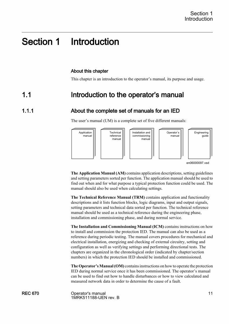
1.1.1 About the complete set of manuals for an IEDThe user’s manual (UM) is a complete set of five different manuals:
en06000097.vsd
Applicationmanual
Technicalreference
manual
Installation andcommissioning
manual
Operator´smanual
Engineeringguide
The Application Manual (AM) contains application descriptions, setting guidelinesand setting parameters sorted per function. The application manual should be used tofind out when and for what purpose a typical protection function could be used. Themanual should also be used when calculating settings.
The Technical Reference Manual (TRM) contains application and functionalitydescriptions and it lists function blocks, logic diagrams, input and output signals,setting parameters and technical data sorted per function. The technical referencemanual should be used as a technical reference during the engineering phase,installation and commissioning phase, and during normal service.
The Installation and Commissioning Manual (ICM) contains instructions on howto install and commission the protection IED. The manual can also be used as areference during periodic testing. The manual covers procedures for mechanical andelectrical installation, energizing and checking of external circuitry, setting andconfiguration as well as verifying settings and performing directional tests. Thechapters are organized in the chronological order (indicated by chapter/sectionnumbers) in which the protection IED should be installed and commissioned.
The Operator’s Manual (OM) contains instructions on how to operate the protectionIED during normal service once it has been commissioned. The operator’s manualcan be used to find out how to handle disturbances or how to view calculated andmeasured network data in order to determine the cause of a fault.
Section 1Introduction
REC 670 Operator's manual1MRK511188-UEN rev. B
11
The IED 670 Engineering guide (EG) contains instructions on how to engineer theIED 670 products. The manual guides to use the different tool components for IED670 engineering. It also guides how to handle the tool component available to readdisturbance files from the IEDs on the basis of the IEC 61850 definitions. The thirdpart is an introduction about the diagnostic tool components available for IED 670products and the PCM 600 tool.
The IEC 61850 Station Engineering guide contains descriptions of IEC 61850station engineering and process signal routing. The manual presents the PCM 600and CCT tool used for station engineering. It describes the IEC 61850 attribute editorand how to set up projects and communication.
1.1.2 About the operator’s manualUse the operator’s manual for instruction on how to perform common tasks duringnormal service.
The operator’s manual contains the following chapters:
• The chapter “Safety information” presents warnings and notices, which the usershould pay attention to.
• The chapter “Overview” describes operations an operator may perform on a dailybasis or when the need arises.
• The chapter “Understand the local human-machine interface” describes how touse the human-machine interface.
• The chapter “Understand the HMI tree” describes the different menu trees.• The chapter “Read measured values” describes how to locate and identify
available measurement data.• The chapter “Event list” describes the location and nature of recorded events.• The chapter “Handle disturbances” describes how to retrieve disturbance
information and reset alarms.• The chapter “Read and change settings” describes how to locate, and change
settings and parameters.• The chapter “Diagnose IED status” describes the location and use of available
diagnostic tools.• The chapter “Test the IED” describes the tests applicable to the IED.• The chapter “Control and supervise the bay” describes how to use the Single
Line Diagram to open and close primary apparatuses.• The chapter “Reset” describes resetting procedures.• The chapter “Authorization”describes user categories and password procedures.• The chapter “Glossary” describes words and acronyms used in the literature
describing the IED.
This manual does not contain any instructions for commissioning or testing.
Section 1Introduction
12 Operator's manual1MRK511188-UEN rev. B
REC 670
1.1.3 Intended audience
GeneralThe operator’s manual addresses the operator, who operates the IED on a daily basis.
RequirementThe operator must be trained in and have a basic knowledge of how to operateprotection equipment. The manual contains terms and expressions commonly usedto describe this kind of equipment.
1.1.4 Related documentsDocuments related to REC 670 Identity numberOperator’s manual 1MRK 511 188-UEN
Installation and commissioning manual 1MRK 511 189-UEN
Technical refernce manual 1MRK 511 187-UEN
Application manual 1MRK 511 190-UEN
Buyer’s guide 1MRK 511 192-BEN
Connection diagram, Single breaker 1MRK 002 801-FA
Connection diagram, Double breaker 1MRK 002 801-MA
Connection diagram, 1 1/2 CB 1MRK 002 801-NA
Configuration diagram A, Single breaker arr. with single or double busbar 1MRK 004 500-90
Configuration diagram B, Double breaker arrangements 1MRK 004 500-91
Configuration diagram C, 1 1/2 breaker arr. for a full bay 1MRK 004 500-92
Connection and Installation components 1MRK 013 003-BEN
Test system, COMBITEST 1MRK 512 001-BEN
Accessories for IED 670 1MRK 514 012-BEN
Getting started guide IED 670 1MRK 500 080-UEN
SPA and LON signal list for IED 670, ver. 1.1 1MRK 500 083-WEN
IEC 61850 Data objects list for IED 670, ver. 1.1 1MRK 500 084-WEN
Generic IEC 61850 IED Connectivity package 1KHA001027-UEN
Protection and Control IED Manager PCM 600 Installation sheet 1MRS755552
Engineering guide IED 670 products 1MRK 511 179-UEN
Latest versions of the described documentation can be found on www.abb.com/substationautomation
1.1.5 Revision notesRevision DescriptionB No functionality added. Minor changes made in content due to problem reports.
Section 1Introduction
REC 670 Operator's manual1MRK511188-UEN rev. B
13

14
Section 2 Safety information
About this chapterThis chapter lists warnings and cautions that must be followed when handling theIED.
2.1 Warnings
Do not touch circuitry during operation. Potentially lethal voltagesand currents are present.
Always connect the IED to protective earth, regardless of theoperating conditions. This also applies to special occasions such asbench testing, demonstrations and off-site configuration. Operatingthe IED without proper earthing may damage both IED and measuringcircuitry and may cause injuries in the event of an accident.
Never remove any screw from a powered IED or from a IEDconnected to powered circuitry. Potentially lethal voltages andcurrents are present.
Always avoid touching the circuitry when the cover is removed. Theproduct contains electronic circuitries which can be damaged ifexposed to static electricity (ESD). The electronic circuitries alsocontain high voltage which is lethal to humans.
Section 2Safety information
REC 670 Operator's manual1MRK511188-UEN rev. B
15

16
Section 3 Overview
About this chapterThis chapter presents a general overview of the Operator's manual.
3.1 Operator overview
The Human machine interface (HMI) on the IED provides an ideal mechanism forthe day to day operation and even advanced use of the IED. The keypad, LCD andLEDs on the front of the IED are what constitute the HMI. Troubleshooting, apparatuscontrol, monitoring, setting and configuring are all possible via this interface.Through the screens and menu elements available, as well as the keypad, the user isable to navigate throughout the menu structure and move from screen to screen. Thisdocument is, to a great extent, arranged in the same way as the IED software isstructured and describes all aspects of operation via the HMI.
The operator can document disturbances so that their causes can be analyzed andevaluated for future reference. For example, the fault currents and voltages at the timeof the fault can be documented. The operator can also retrieve data about protectedobjects, providing further information for fault analysis. This implies viewing themean value of current, voltage, power and frequency or primary and secondarymeasured phasors. The operator can check the IED status at any time.
In some cases the operator may need to change the way the IED operates. This mightinclude changing the active setting group or a parameter value. This must always bedone strictly according to applicable regulations because un-authorized changes maylead to severe damage of the protected object especially if a fault is not properlydisconnected.
3.2 Identify the IED
To identify the IED, open the diagnostics menu. The identity of the IED along withother data is found under:
Diagnostics/IED status/Product Identifiers
The type of IED, the main function type, its serial number, ordering number andproduction date are found here.
Section 3Overview
REC 670 Operator's manual1MRK511188-UEN rev. B
17

18
Section 4 Understand the local human-machine interface
About this chapterThis chapter describes the display, its keys (buttons) and LEDs that make up the HMI.How the keys are used to navigate the HMI, how to interpret the graphic informationon the LCD and, what the LEDs indicate is explained in the sections that follow.
4.1 Overview
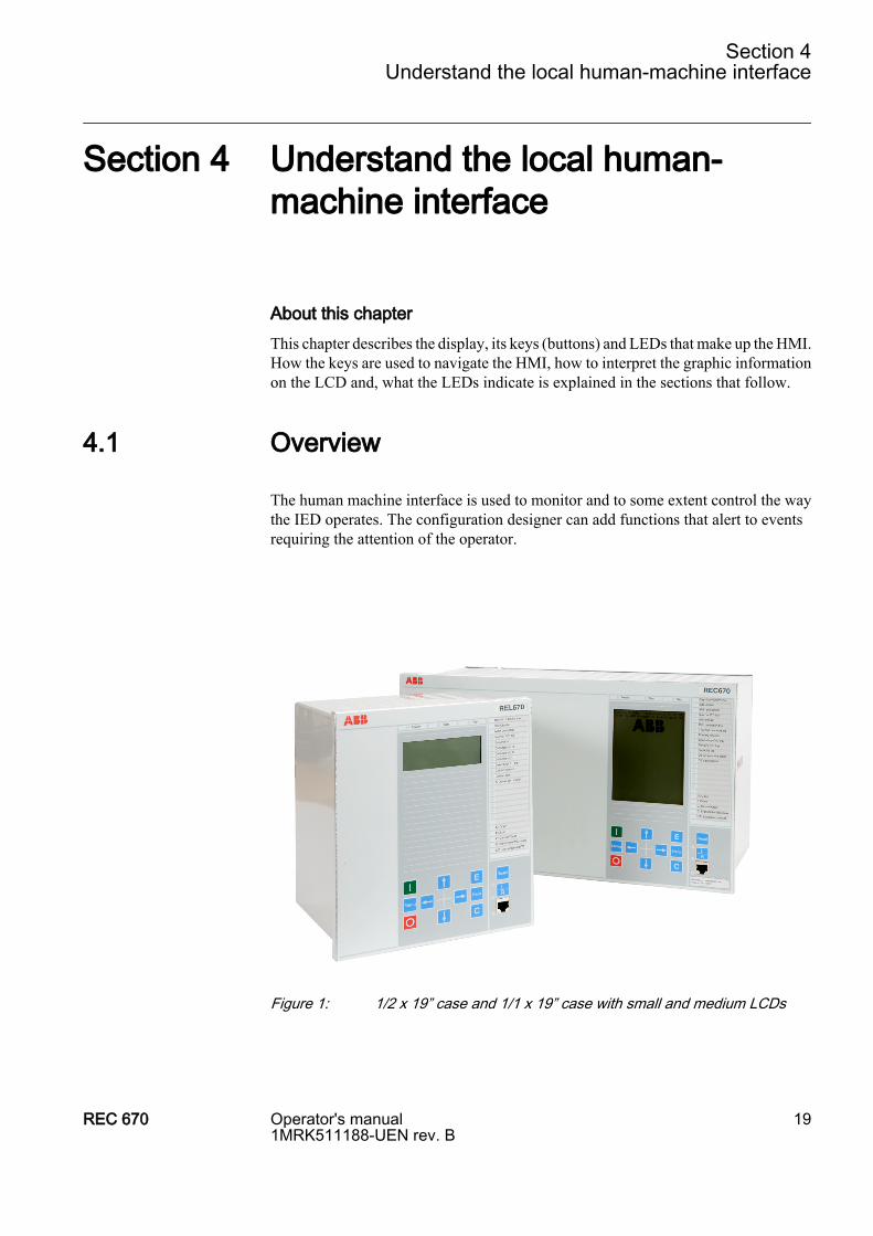
The human machine interface is used to monitor and to some extent control the waythe IED operates. The configuration designer can add functions that alert to eventsrequiring the attention of the operator.
Figure 1: 1/2 x 19” case and 1/1 x 19” case with small and medium LCDs
Section 4Understand the local human-machine interface
REC 670 Operator's manual1MRK511188-UEN rev. B
19
4.2 Keypad
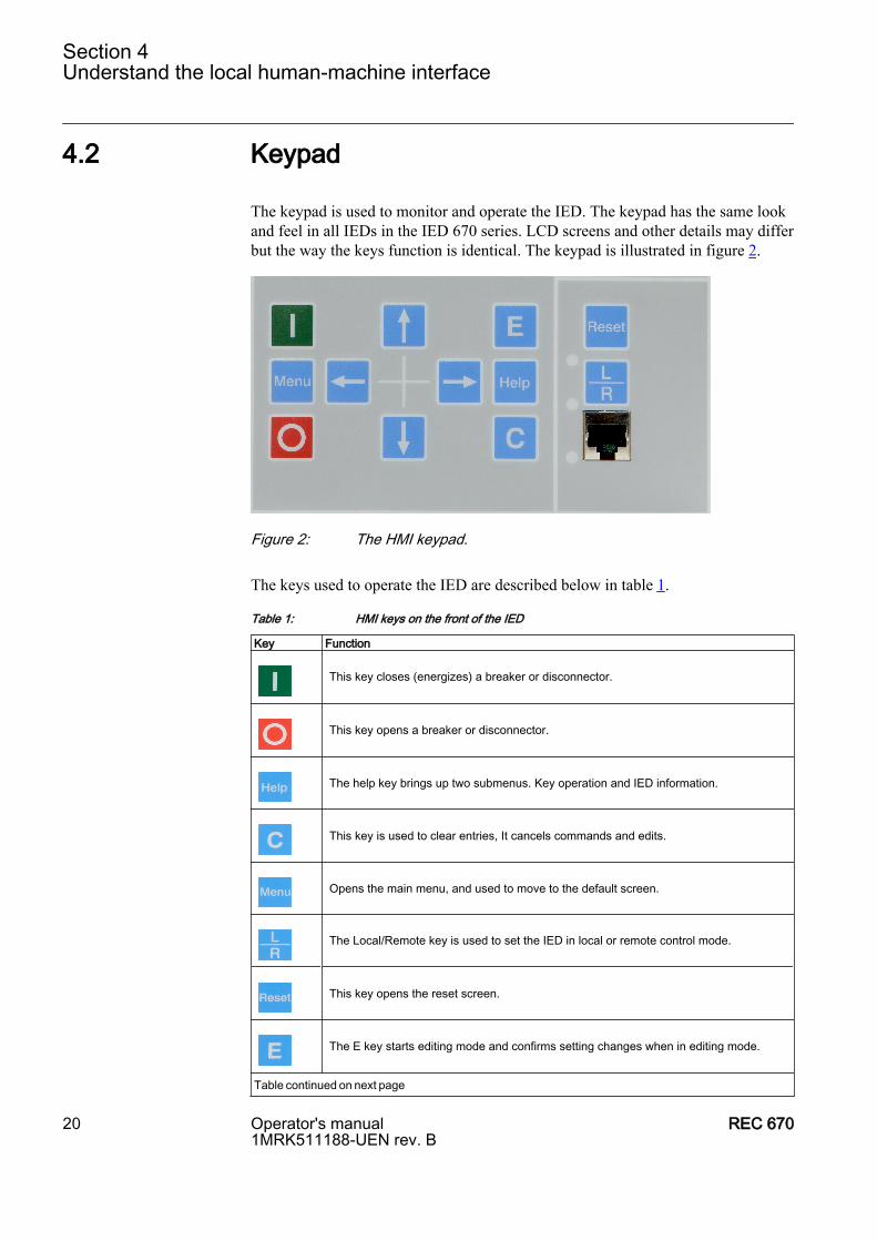
The keypad is used to monitor and operate the IED. The keypad has the same lookand feel in all IEDs in the IED 670 series. LCD screens and other details may differbut the way the keys function is identical. The keypad is illustrated in figure 2.
Figure 2: The HMI keypad.
The keys used to operate the IED are described below in table 1.
Table 1: HMI keys on the front of the IED
Key Function This key closes (energizes) a breaker or disconnector.
This key opens a breaker or disconnector.
The help key brings up two submenus. Key operation and IED information.
This key is used to clear entries, It cancels commands and edits.
Opens the main menu, and used to move to the default screen.
The Local/Remote key is used to set the IED in local or remote control mode.
This key opens the reset screen.
The E key starts editing mode and confirms setting changes when in editing mode.
Table continued on next page
Section 4Understand the local human-machine interface
20 Operator's manual1MRK511188-UEN rev. B
REC 670

Key Function The right arrow key navigates forward between screens and moves right in editing mode.
The left arrow key navigates backwards between screens and moves left in editing mode.
The up arrow key is used to move up in the single line diagram and in menu tree.
The down arrow key is used to move down in the single line diagram and in menu tree.
4.3 Key activated screens
4.3.1 The Help screenThe help screen is activated by pressing the Help key on the front panel of the IED.It includes the submenu listed below:
• General operation
The General Operation submenu provides information about the IED keypad.
The I and O keys are used to open (OFF) and close (ON) breakers and disconnectorswhen using the Single Line Diagram (SLD) in direct control situations.
4.3.2 The Reset screenThe reset screen is activated by the Reset key on the front panel of the IED or via themain menu. The reset screen includes the submenus listed below:
• Reset LEDs• Reset lockout• Reset counters• Reset temperature functions
The Reset LEDs submenu consists of two lower level menus which are the “Start andtrip LEDs” and “All indication LEDs” submenus. To reset a counter, the actualcounter must first be selected. The submenus and the their structures are discussed inthe “Reset” chapter of this document.
Section 4Understand the local human-machine interface
REC 670 Operator's manual1MRK511188-UEN rev. B
21

4.4 LCD
4.4.1 SmallThe small sized HMI is available for 1/2, 3/4 and 1/1 x 19” case. The LCD on thesmall HMI measures 32 x 90 mm and displays 7 lines with up to 40 characters perline. The first line displays the product name and the last line displays date and time.The remaining 5 lines are dynamic. This LCD has no graphic display potential.
4.4.2 MediumThe 1/2, 3/4 and 1/1 x 19” cases can be equipped with the medium size LCD. This isa fully graphical monochrome LCD which measures 120 x 90 mm. It has 28 lineswith up to 40 characters per line. To display the single line diagram, this LCD isrequired.
4.5 LED
The LED module is a unidirectional means of communicating. This means that eventsmay occur that activate a LED in order to draw the operators attention to somethingthat has occurred and needs some sort of action.
4.5.1 Status indication LEDsThere are three LEDs above the LCD. The information they communicate is describedin the table below.
LED Indication InformationGreen:
Steady In service
Flashing Internal failure
Dark No power supply
Yellow:
Steady Dist. rep. triggered
Flashing Terminal in test mode
Red:
Steady Trip command issued
4.5.2 Indication LEDs
Section 4Understand the local human-machine interface
22 Operator's manual1MRK511188-UEN rev. B
REC 670
The LED indication module comprising 15 LEDs is standard in IED 670s. Its mainpurpose is to present an immediate visual information for protection indications oralarm signals.
There are alarm indication LEDs and hardware associated LEDs on the right handside of the front panel. The alarm LEDs are found to the right of the LCD screen.They can show steady or flashing light. Flashing would normally indicate an alarm.The alarm LEDs are configurable using the PCM 600 tool. This is because they aredependent on the binary input logic and can therefore not be configured locally onthe HMI. Some typical alarm examples follow:
• Bay controller failure• CB close blocked• Interlocking bypassed• SF6 Gas refill• Position error• CB spring charge alarm• Oil temperature alarm• Thermal overload trip
The RJ45 port has a yellow LED indicating that communication has been establishedbetween the IED and a computer.
The Local/Remote key on the front panel has two LEDs indicating whether local orremote control of the IED is active.
4.6 LHMI setup and test screen
The contrast setting of the LCD can be adjusted from the LHMI menu tree when theIED has started or from the PST tool in PCM 600. The contrast setting adjusted withone of these methods is an offset to a factory set basic contrast setting.
Normally the basic contrast setting is not changed, but can if needed be adjusted asfollows:
Activate the setup and test screen for the LHMI by keeping the Reset key pressedimmediately after the dc power to the IED has been applied.
By pressing keys according to information on the setup and test screen
Section 4Understand the local human-machine interface
REC 670 Operator's manual1MRK511188-UEN rev. B
23
• the basic contrast level of the LCD screen can be changed
• the LCD screen can be toggled to inverse mode
• the indication LEDs can be tested
Press the I key to save and exit the screen and wait for the IED to start. Observe thatonly the basic contrast setting will be saved.
4.7 How to navigate
4.7.1 ReadTo read values and access information about the objects being monitored the operatormust navigate the menu tree using the arrow keys. The active submenu or value ishighlighted.
Navigation is as follows:
• Press the right arrow key to move to the main menu.• Press the down arrow key to move from the Single line diagram to the desired
submenu.• Use the right arrow key to move downwards in the HMI tree until the desired
parameter is displayed.• Press C and the down arrow key simultaneously to see the next page in the
parameter screen.• Press C and the up arrow key simultaneously to return to the previous parameter
screen.• Use the left arrow key to navigate back up the menu tree.
4.7.2 ChangeTo change a parameter setting the following steps should be followed:
1. Navigate to the desired parameter or quantity using the arrow keys.2. Press the E key when the parameter to be changed is highlighted.3. Move between digits or letters using the left and right arrow keys.4. Use the up and down arrow keys to change the digit or letter concerned.5. Press the E key once the desired changes have been made.6. Press the left arrow key to move up a level in the HMI tree.7. You will be prompted to confirm the changes, use the left and right arrow keys
to toggle between yes and no in the pop up window and press the E key to confirmyour choice.
8. Press the left arrow key to move up to the next level in the HMI tree.
Section 4Understand the local human-machine interface
24 Operator's manual1MRK511188-UEN rev. B
REC 670
4.7.3 ControlThe HMI offers the operator the opportunity to exercise direct local control overbreakers and other apparatuses in the bay using the graphic display and designatedkeys on the front panel of the IED.
By pressing the L/R key until the uppermost of the two LEDs next to the key lightsup, local operator control can be exercised from the HMI.
An apparatus is selected using the up and down arrow keys. The active apparatus ishighlighted in the display.
The Open or Close commands are issued by pressing the O or I keys;
The user is requested to confirm the command in a pop-up window.
E confirms a command; C cancels it.
Interlocking or synchrocheck conditions may cause other query windows to pop-up.
Section 4Understand the local human-machine interface
REC 670 Operator's manual1MRK511188-UEN rev. B
25

26
Section 5 Understand the HMI tree
About this chapterThis chapter describes the structure of the HMI. The main menu includes submenussuch as Measurements, Events, Disturbance Report, Settings, Diagnostics, Test andReset. These branch out into a typical tree structure.
5.1 Overview
The local HMI has the following main menu:
• Control• Measurements• Events• Disturbance records• Settings• Diagnostics• Test• Reset• Authorization• Language
Each main menu item can have several other submenus.
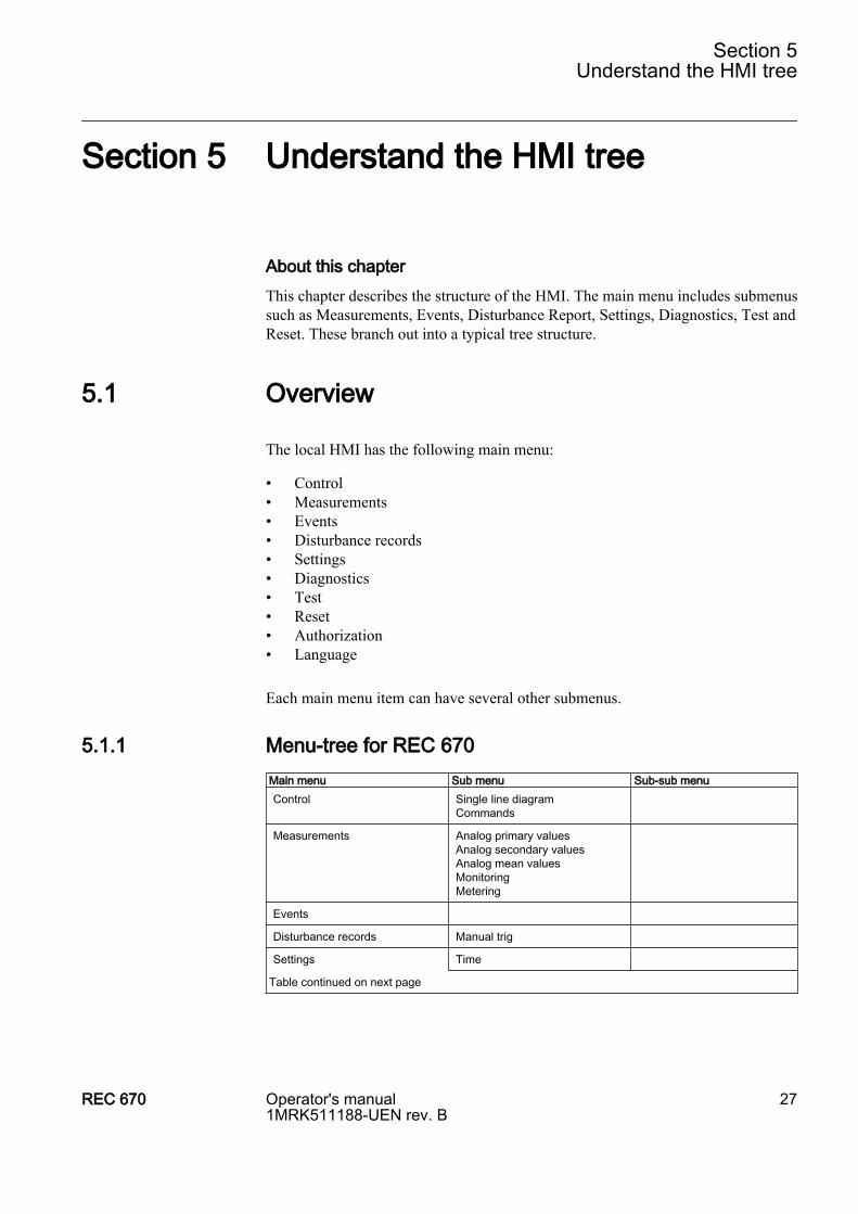
5.1.1 Menu-tree for REC 670Main menu Sub menu Sub-sub menuControl Single line diagram
Commands
Measurements Analog primary valuesAnalog secondary valuesAnalog mean valuesMonitoringMetering
Events
Disturbance records Manual trig
Settings Time
Table continued on next page
Section 5Understand the HMI tree
REC 670 Operator's manual1MRK511188-UEN rev. B
27

Main menu Sub menu Sub-sub menu General settings Power system
CommunicationAnalog modulesI/O modulesHMICurrent protectionVoltage protectionControlMonitoringMetering
Setting group N Differential protectionCurrent protectionVoltage protectionFrequency protectionMultipurpose protectionScheme communicationSecondary system supervisionControlMonitoringLogic
Activate setting group
Diagnostics Internal eventsIED status
Test IED test modeBinary input valuesBinary output valuesFunction test modesFunction statusLED testLine differential test
Reset Reset countersReset internal eventlistReset LEDsReset lockoutReset temperature
Authorization
Language
Section 5Understand the HMI tree
28 Operator's manual1MRK511188-UEN rev. B
REC 670
Section 6 Read measured values
About this chapterThis chapter describes measurement categories and how to locate them using theHMI. Each measurement category has a section of its own that includes a generaldescription of the type of quantity being measured and the path in the local HMI tothe measurement.
6.1 Overview
The measurement menu contains primarily analog measurement data. Externalsignals can also be viewed as they are or as they appear in the Signal Matrix Tool(SMT). These signals are a virtual representation of the hard wired signals on thevarious inputs and outputs. The SMT is only accessible via the PCM and is intendedto simplify the configuration of the IED. It allows hardware changes to be madewithout having to reconfigure the internal logic. Signals that can be used in the SMTare indicated with the Suffix SMT.
The functions available under measurements are outlined below.
1. Analog primary values are the quantities measured on the primary side of thecurrent and voltage transformers (CTs and VTs).
2. Analog secondary values are the quantities measured on the secondary side ofthe current and voltage transformers. These are the quantities measured on theTransformer module (TRM) inputs.
3. Analog mean values are the quantities measured at the inputs of the milliamperemodule (MIM).
4. Under Monitoring a number of submenus are available. These include Servicevalues, Current phasors, Voltage phasors, Current sequence components andVoltage sequence components.
5. Metering displays the pulse counter function. The measurements available hereshow pulse counter status data.
All measurement descriptions in this document reflect the maximum number ofhardware units possible in any application. In reality the hardware in the IED will bechosen according to a particular application. For example, it is possible to equip a 1/1x 19” case IED with 14 I/O modules. In reality fewer I/O modules may be installed.In the measurements menu the operator will only see data from the hardware andsoftware installed.
Section 6Read measured values
REC 670 Operator's manual1MRK511188-UEN rev. B
29
6.2 View analog primary values
6.2.1 OverviewThe analog primary values are analog quantities measured on the primary side of theTRM and reflect the actual current or voltage on the primary side of the VTs and CTs.The ratio is adjusted under settings and also depends on the rating of the TRM. 24primary values and phase angles are displayed in this view.
Measurements/Analog Primary Values
Displays the quantities measured by the transformer module (TRM). For each channelused the amplitude of the voltage or current and its phase angle is shown. The statusof the module is always shown and channels not in use are indicated with theabbreviation NC. Data from up to two TRMs and four LDCMs can be viewed. Allcurrents and voltages are given in RMS values.
6.3 View analog secondary values
6.3.1 OverviewAnalog secondary values shows secondary CT currents and VT voltages. These arethe actual current and voltage values at the TRM inputs.
Measurements/Analog Secondary Values
Displays up to 24 channels with secondary CT and VT data. RMS values are shown.
6.4 View analog mean values
6.4.1 OverviewMeasurements from the Milliampere Input Module (MIM) are found in this part ofthe measurements menu. Data from either the hard wired mA module or the SignalMatrix Tool mA modules are shown here.
6.4.1.1 mA input module (MIM)
Measurements/Analog Mean Values/mA modules/MIM
Displays input data from the milli-ampere module which has six inputs. Each inputhas a range of +/- 20 mA. The value displayed on the screen is however dependant
Section 6Read measured values
30 Operator's manual1MRK511188-UEN rev. B
REC 670

on the settings for the Milli-ampere Module. In the menu for settings, the range anda transformation factor can be adjusted to suit the application. This means that aninput 3 mA may be displayed as temperature of 45 degrees. The output values shownare without units.
6.5 View monitoring values
6.5.1 Service valuesMeasurement/Monitoring/ServiceValues(MMXU)/SVR
Displays up to three instances of SVR with measured values for S, P, Q, PF, U, I,ILead, ILag and F.
6.5.2 Current phasorsMeasurement/Monitoring/Current Phasors/CP
All three phase currents and their phase angles are displayed here. As many as 10 setsof current data can be shown.
6.5.3 Voltage phasors
Measurements/Monitoring/Voltage phasors/VP
Phase to phase voltages and phase angles are displayed here. Up to three sets ofvoltage data can be displayed.
Measurement/Monitoring/Phase-Earth/VN
Phase to earth voltages and phase angles are displayed here. Up to three sets of voltagedata can be displayed.
6.5.4 Current sequence componentMeasurements/Monitoring/Current Sequence Components (MSQI)/CSQ
The current sequence component under monitoring displays the positive (I1),negative (I2) and zero sequence (I0) current values for a three phase line, bothmagnitude and phase angle for each component are displayed. These indicate howwell balanced a system is. In an ideal balanced system the zero sequence currentshould be zero, the positive sequence current should be equal to the current of eachphase with the same phase angle (relative to GPS) as the L1 phase signal and thenegative sequence current should be zero.
Section 6Read measured values
REC 670 Operator's manual1MRK511188-UEN rev. B
31
6.5.5 Voltage sequence componentMeasurements/Monitoring/Voltage Sequence Components (MSQI)/VSQ
The Voltage sequence component displays the positive (U1), negative (U2) and zero(U0) sequence components in the system, and includes the magnitude and phase angleof each component. Three sets of values are shown. This data indicates how wellbalanced the system is.
6.6 View metering values
Measurements/Metering/Pulse counter/PC
The output data generated from the pulse counter function include data about thestatus of the counter and counter values.
Measurements/Metering/ThreePhEnergMeas/ETP
The output data generated from the energy measuring function includes activeforward/reverse energy and reactive forward/reverse energy.
Section 6Read measured values
32 Operator's manual1MRK511188-UEN rev. B
REC 670
Section 7 Event list
About this chapterThis chapter describes how to find and read the event list.
7.1 View events
7.1.1 OverviewEvents displays recorded events such as trips and breaker opened or closed.
Events
Displays a list of events in chronological order and where each event has a time stamp.The latest event is at the top of the list.
Section 7Event list
REC 670 Operator's manual1MRK511188-UEN rev. B
33

34
Section 8 Handle disturbances
About this chapterThis chapter describes disturbance detection and handling. This includes resettingLED alarms, triggering disturbance reports, fault distance calculation and the viewingof several fault indicators.
8.1 Identify a disturbance
A disturbance record can be generated manually by using the Manual Trigfunctionality in the HMI menu. Other disturbance records are generated automaticallyin the system dependant on the settings made. Disturbance reports generate adisturbance sequence number and are time tagged. The fault location and fault loopare among the data generated in a fault record. Under each fault report there are fivecategories of information available. These are described in the sections that follow.
8.2 View disturbance record details
8.2.1 View general informationBy choosing General information after selecting a disturbance record in the list ofdisturbance records the screen generated displays information about the disturbancesuch as its sequence number, time of occurrence, trig-signal, fault location and faultloop. The path in the HMI is shown below.
Disturbance records/Manual trig
8.2.2 View disturbance indicationsThe Indications section of a disturbance record displays the recording number and,the time and date of the disturbance. The path in the HMI is shown below.
Disturbance records/Record xx/Indications
8.2.3 View event recordingsThe Event recording section in the Disturbance report shows the recording number.The path in the HMI is shown below.
Disturbance records/Record xx/Event recording
Section 8Handle disturbances
REC 670 Operator's manual1MRK511188-UEN rev. B
35

8.2.4 View trip valuesIn the Trip values section of a disturbance recording both the pre-fault and the faultvalues for current, voltage and phase angle can be viewed. The recording number andTrig time are also displayed. The path in the HMI is shown below.
Disturbance records/Record xx/Trip Values
8.2.5 Recalculate distance to faultThis screen displays the fault loop with reactance and resistance values. To recalculatethe distance to fault, press the E key on the keypad.
In the Recalculate distance to fault section in a disturbance record it is possible notonly to view fault data but to recalculate the distance to a fault. By taking into accountperipheral influences like the resistance and reactance of other lines in the immediatenetwork area new distances can be calculated. The reactance and resistance in theforward direction have the suffix B and in the reverse direction they have the suffixA.
Recalculation may be necessary in cases where the data from a different fault loopneeds to be calculated. In three phase faults only one loop is shown in the disturbancerecord. When recalculating, a different fault loop can be selected. The path in theHMI is shown below.
Disturbance records/Record xx/Recalc distance to fault
8.3 Trigger a disturbance report manually
Using the manual trigger generates an instant disturbance report. Use this function toget a snapshot of the monitored line. Follow the path below and answer yes in theExecute manual trig dialog box.
Disturbance Records/Manual Trig
Section 8Handle disturbances
36 Operator's manual1MRK511188-UEN rev. B
REC 670

Section 9 Read and change settings
About this chapterThis chapter describes how to find and change settings and parameters. The chapteris divided into two sections which match the way the two categories of settings aredivided up in the HMI. The General settings group consists of those parameters thatcause an automatic restart of the IED. The Setting group N consists of six groups ofsettings with default values for all parameters. These do not require or cause a restartonce they have been changed. Time, synchronization and the activation of settinggroups are also dealt with here.
It takes a minimum of three minutes for the IED to save the newsettings, during this time the DC supply must not be turned off.
9.1 System time and synchronization
9.1.1 System timeSettings/Time/System time
Under System time, the system clock date and time are set.
9.1.2 Time synchronization
9.1.2.1 Overview
The synchronization settings are divided into categories Time synch, Time synchBIN, Time synch SNTP, Time synch DST Begin, Time synch DST End, Time synchtime zone and Time synch IRIG-B. The settable parameters are found under eachcategory.
9.1.2.2 TimeSynch
Settings/Time/Synchronization/TimeSynch
Here the parameters FineSyncSource, CourseSyncSrc and SyncMaster are switchedon or off.
Section 9Read and change settings
REC 670 Operator's manual1MRK511188-UEN rev. B
37
9.1.2.3 TimeSynchBIN
Settings/Time/Synchronization/TimeSynchBIN
Binary input synchronization settings available here are the position of the of themodule, the number of the binary input and the detection mode.
9.1.2.4 TimeSynchSNTP
Settings/Time/Synchronization/TimeSynchSNTP
Here the IP addresses for the Simple Network Time Protocol servers are set.
9.1.2.5 TimeSynchDSTBegin
Settings/Time/Synchonization/TimeSynchDSTBegin
The starting point for Daylight Savings Time is set here.
9.1.2.6 TimeSynchDSTEnd
Setttings/Time/Synchronization/TimeSynchDSTEnd
The end point of Daylight Savings Time is set here.
9.1.2.7 TimeZone
Settings/Time/Synchronization/TimeSynchTimeZone
The time zone according to Coordinated Universal Time (UTC) is set here.
9.1.2.8 TimeSynch IRIG-B
Settings/Time/Synchronization/TimeSynchIRIG-B
The type of input, time domain, type of encoding and time zone for IRIG-B are sethere.
9.2 General settings
Parameters under General settings that are changed will cause the IED to restart. Thisoccurs automatically and requires no manual intervention.
Section 9Read and change settings
38 Operator's manual1MRK511188-UEN rev. B
REC 670
9.2.1 Power system
9.2.1.1 Overview
Under Power system in General settings there are four parameter categories. Theseare Identifiers, Primary values, three phase analog group and three phase analog sumgroup.
9.2.1.2 Identifiers
Settings/General Settings/Power System/Identifiers
Displays list with Station Name, Station Number, Object Name, Object Number, UnitName and Unit Number.
9.2.1.3 Primary values
Settings/General Settings/Power System/Primary Values
Displays the system frequency.
9.2.2 Communication
9.2.2.1 Overview
The parameter settings for communications are found under General Settings\Communications. Communication settings cover network interfaces, protocol,remote communication and reception of interlocking information.
9.2.2.2 TCP-IP
Settings/General settings/Communication/Front port
The IP Address and IP mask for the ethernet port on the front panel of the IED areset here. These are generally used when connecting a PC directly to the IED.Remember that this is a static IP address and that the appropriate network settingsmust also be made in the PC.
Settings/General settings/Communication/TCP-IP/Rear OEM-Port AB
The IP address, IP mask and Link for the Optical Ethernet card at the rear of the IEDare set here.
Settings/General settings/Communication/TCP-IP/Rear OEM-Port CD
The same as the above but with different IP address if a second port is used.
Settings/General settings/Communication/TCP-IP/Gateway
Section 9Read and change settings
REC 670 Operator's manual1MRK511188-UEN rev. B
39
If a gateway is used to access the system the address to that gateway is entered here.
9.2.2.3 SPA, LON and IEC 60870–5–103 settings
Rear Optical LON portThe menu for the rear optical LON port has five submenus for various settingsaffecting LON parameters. The HMI paths to these submenus and their contents aredescribed below.
Settings/General settings/Communication/SLM configuration/Rear opticalLON port/General
In the General submenu there are three settings. These are for the Subnet address, theNode address and the NeuronID.
Settings/General settings/Communication/SLM configuration/Rear opticalLON port/ServicePinMessage
In this submenu a Service pin message can be generated. This is similar to a “ping”in traditional networks. This sends a signal to another node in the system which isthen made aware of the Neuron ID of LON port and can respond to that port.
Settings/General settings/Communication/SLM configuration/Rear opticalLON port/ADE
The Application Data Event (ADE) menu is where operation of LON is set on or offand where the data exchange speed can be set. If LON is used primarily to send eventdata then the appropriate setting is slow. Should LON be used, for example, as achannel for TRIP signals then the setting fast would be appropriate.
Settings/General settings/Communication/SLM configuration/Rear opticalLON port/SPA
Settings for SPA over LON are made here. The operation setting is used to switchthe function on or off and the slave address setting is where the slave address isentered.
Settings/General settings/Communication/SLM configuration/Rear opticalLON port/Horizontal communication
This setting is used to activate or deactivate horizontal communication.
Rear optical SPA-IEC port
Settings/General settings/Communication/SLM configuration/Rear opticalSPA-IEC port
In this submenu SPA or IEC is chosen and the necessary settings for the respectivecommunication protocols are made.
Settings/General settings/Communication/SLM configuration/Rear opticalSPA-IEC port/Protocol selection SPA or IEC103 operation.
Section 9Read and change settings
40 Operator's manual1MRK511188-UEN rev. B
REC 670
SPA and IEC cannot run at the same time and in this submenu one of the options ischosen.
Settings/General settings/Communication/SLM configuration/Rear opticalSPA-IEC port/SPA
When SPA is chosen the baud rate and slave address are set here.
Settings/General settings/Communication/SLM configuration/Rear opticalSPA-IEC port/IEC60870–5–103
When IEC 60870–5–103 is used the settings Slave address, Baud rate, RevPolarityand CycMeasRepTime are done here.
9.2.2.4 LDCM
Settings/General settings/Communication/LDCM configuration/LDCM
Four identical sets of settings for Remote Binary Communication (CRB) and four forRemote Multi Communication (CRM). The multi communication block can sendboth binary and analog data whereas the binary can only send binary data.
Each instance of CRB has seven settable parameters where the channel mode can beset on or off, terminal numbers can be entered, synchronization can be set to masteror slave and opto power can be set high or low.
Each instance of CRM has 17 settable parameters. These include those above andothers such as transmission delay and transmission current.
9.2.2.5 Station communication
Multicommand send
Settings/General settings/Communication/Station communication/MulticommandSend/MT
The up to ten instances of MulticommandSend settings allow the user to adjust themaximum and minimum cycle time.
Multicommand receive
Settings/General settings/Communication/Station communication/Multicommand receive/CM
The up to 60 instances of MulticommandReceive settings available here allow theuser to adjust the maximum and minimum cycle time, the pulse duration and modeof operation. The mode of operation is either steady or pulsed.
Settings/General Settings/Communication/Station communication/IEC61850–8–1
Section 9Read and change settings
REC 670 Operator's manual1MRK511188-UEN rev. B
41
Includes settings for the IED name, operation (on/off) and GOOSE.
GOOSE Binary receive
Settings/General settings/Communication/Station communication/GOOSEBinReceive/GB
There are up to ten sets of settings here with one parameter (GB 01– GB10) per setting.The setting is Operation ON or OFF.
Settings/General settings/Communication/Station Communication/ReceivingInterlInfo/GR
Includes up to 59 parameters (GR01–GR59) for horizontal communication viaGOOSE. Each instance or set can be switched on or off via the operation parameter.
Settings/General settings/Communication/Station Communication/DNP3.0
The DNP 3.0 related parameters are found here.
9.2.3 Analog modules
9.2.3.1 Overview
Under Analog modules in the General settings menu there are settings for Analoginputs and I/O modules. Within each instance of analog input there are settings forall 12 channels that include the name of the channel, star point of the CT circuit, theprimary and secondary values from the measuring transformers (CTs and VTs). Thechannel type and ratings are shown but cannot be changed.
The settings for binary inputs and outputs even include the milliampere inputmodules. A mix of up to 14 instances of BIM, BOM and IOM is possible dependingon the physical configuration of the IED. Operation ON or OFF can be set for all ofthese and for the BIMs oscillation release and oscillation block settings are available.These settings are on board level and apply to all binary inputs or outputs on a board.
9.2.3.2 Analog modules
Settings/General Settings/Analog modules/AnalogInputs
Displays all variations of analog input modules with parameters. The analog inputmodules have different combinations of current and voltage inputs. Each channel hasparameters where the type of channel is set, the primary and secondary values fromVTs and CTs and for Current Transformers the star point location (line side or busbarside) is set.
Settings/General Settings/Analog modules/3PhAnalogGroup/PR
Section 9Read and change settings
42 Operator's manual1MRK511188-UEN rev. B
REC 670
Here, settings for the Fourier filters, the minimum system voltage required to measurefrequency, the item designation of CTs or VTs, and the system voltage are set. Thesesettings are required by the preprocessing blocks and are usually only adjusted duringthe initial engineering phase.
Setting/General Settings/Analog modules/3PhAnalogSummationGroup/SU
Here is where the settings for the summation block are done. The summation type,Fourier filter reference frequency, minimum voltage for frequency measurement andthe system voltage are some of the parameters that can be set here.
Settings/General Settings/Analog modules/Reference channel service values
The phase angle reference is set here.
9.2.3.3 I/O modules
Settings/General Settings/I/O Modules
Settings for binary inputs and outputs (BIM, BOM, IOM), and under each binarymodule there are one or more adjustable parameters. In the I/O modules folder thereis also a “reconfigure” setting that starts a dialog box prompting the user to confirmor cancel the command. Since only I/O modules installed in the IED are shown, theparameters available for setting depend on the physical configuration of the IED. AllI/O modules include the operation parameter which enables the operator to switchthe module on or off.
The milliampere modules (MIMs) are also found in the I/O Modules folder.Parameters possible to set here are dead band settings and various current thresholdvalues.
9.2.4 HMI
9.2.4.1 Overview
Under HMI in General settings there are submenus for LEDs, Screen, Functions,Reference channel service values and the Change lock function. In the LED submenuthere are settings for operation, illumination times, and sequence types for the LEDson the IED front panel. In the Screen submenu Contrast level, Default screen, Autorepeat and Timeout display can be set. In the Functions submenu the Event list sortingorder and Distance presentation can be set.
9.2.4.2 LEDs
Settings/General settings/HMI/LEDs
Section 9Read and change settings
REC 670 Operator's manual1MRK511188-UEN rev. B
43

Parameters such as Operation, tRstart, tMax and 15 instances of SeqTypeLED canbe set here. The SeqTypeLED offers several options for the type of illuminationsequence the LEDs should follow.
9.2.4.3 Screen
Settings/General Settings/HMI/Screen
Local HMI setting parameters such as Language, Contrast level and Default menucan be set here.
9.2.4.4 Functions
Settings/General Settings/HMI/Functions
The settings here are used to determine the way information is presented in the HMI.The two parameters available here allow the user to choose between miles andkilometers for the presentation of distance and to determine the order in which eventsare presented in the Event list.
9.2.4.5 Change lock
Settings/General settings/HMI/Change lock
The operation of the Change lock function can be activated or deactivated here.
9.2.5 Control
9.2.5.1 Overview
Under Control in General settings, parameters for Apparatus control can be adjusted.These are the parameters for among others Bay control, Switch controller,Reservation input, Circuit breakers and Circuit switches. The parameters includedelay times, dependencies, pulse times and characteristics.
9.2.5.2 Bay control (CBAY)
Settings/General Settings/Control/Apparatus Control/Bay Control/CB
Displays up to six instances of the bay control function (CB) with a setting that givesthe local operator priority over the remote operator or vice versa.
9.2.5.3 Reservation input
Settings/General Settings/Control/Apparatus Control/ReservationInput/RE
Displays available instances of the Reservation input function (RE) with one settableparameter per function for future use.
Section 9Read and change settings
44 Operator's manual1MRK511188-UEN rev. B
REC 670
9.2.5.4 Bay reserve (CRSV)
Settings/General Settings/Control/Apparatus Control/Bay Reserve/CR
Displays up to four instances of the bay reserve function (CR) with nine parametersettings. The first is for setting the supervision time to cancel a reservation and theother eight are for the reservation of the own bay only at the selection of an apparatus.
9.2.5.5 Switch controller (CSWI)
Settings/General Settings/Control/Apparatus Control/SwitchController/CS
Displays instances of the switch controller function (CS) with eight settableparameters. These are settings for the control model, position dependency and variousthreshold times.
9.2.5.6 Circuit breaker (XCBR)
Settings/General Settings/Control/Apparatus Control/CircuitBreaker/XC
Displays available instances of the circuit breaker function with parameter settingsfor various time limits and pulse lengths. For example, different circuit breakers mayrequire different pulse lengths to react. The setting tOpenPulse is used to set the lengthof the pulse required to open a breaker.
9.2.5.7 Circuit switch (XSWI)
Settings/General Settings/Control/Apparatus Control/CircuitSwitch/XS
Displays available instances of the circuit switch function (XS) with a number ofsettable parameters per instance for time and pulse settings, output reset and switchtype.
9.2.5.8 Local/Remote switch (LocalRemote, LocRemControl)
Settings/General Settings/Control/Apparatus control/LocalRemote/LR
Displays available instances of the local/remote function (LR) that permit the user toset the control mode.
9.2.6 Control commands
9.2.6.1 Single command
Settings/General settings/Control/Commands/Single command/CD
The mode for single command is set here.
Section 9Read and change settings
REC 670 Operator's manual1MRK511188-UEN rev. B
45
9.2.6.2 Logic rotating switch (GGIO)
Settings/General settings/Control/Commands/Selector switch (GGIO)/SL
A number of selector switches (LRS) can be configured in the system. These aresubstitutes for rotating physical switches. There is only one parameter setting perswitch. This is StopAt Extremes which is used to disable or enable the end positionof the switch.
9.2.6.3 Selector mini switch (GGIO)
Settings/General settings/Control/Commands/Versatile switch/VS
Parameters such as control model according to IEC61850 and operation mode for theversatile switch is set here.
9.2.6.4 Tap changer control and supervision (YLTC, 84)
Settings/General settings/Control/TransformerTapControl/TCL
Tap changer parameters such as tap positions for low and high voltage and type ofcode conversion are set here.
9.2.6.5 Tap changer control and supervision (YLTC, 84)
Settings/General settings/Control/TransformerTapControl/TCM
Tap changer parameters such as tap positions for low and high voltage and type ofcode conversion are set here.
9.2.6.6 Automatic voltage control for tapchanger (ATCC, 90)
Settings/General settings/Control/Transformer Voltage Control/VCP
Transformer voltage control parameters such as transformer name, transformerreactance and selections for alarm and block functions are set here.
9.2.6.7 Automatic voltage control for tapchanger (ATCC, 90)
Settings/General settings/Control/Transformer Voltage Control/VCS
Transformer voltage control parameters such as transformer name, transformerreactance and selections for alarm and block functions are set here.
Section 9Read and change settings
46 Operator's manual1MRK511188-UEN rev. B
REC 670
9.2.7 Monitoring
9.2.7.1 Overview
Under monitoring there are parameters for setting Service values, current phasors,Voltage phasors, Disturbance reports, Fault locator and the Measured value expanderblock.
9.2.7.2 Measurements (MMXU)
Settings/General Settings/Monitoring/ServiceValues/SVR
Displays three instances of SVR.
9.2.7.3 Current phasors
Settings/General Settings/Monitoring/Current phasors/CP
Displays available instances of the current phasor function (CP) with output regardingcurrent amplitude, current range, phase angle, zero sequence current magnitude andnegative sequence current magnitude.
9.2.7.4 Voltage phasors
Settings/General Settings/Monitoring/Voltage phasors/Phase-Phase
Displays available instances of the voltage phasor function (VP) with output data forphase to phase voltage, (amplitude, phase angle). The setting parameters forsupervision levels, deadband etc. are set here
Settings/General Settings/Monitoring/Voltage phasors/Phase-Earth
Displays available instances of the voltage phasor function (VN) with output data forphase to earth voltage, (amplitude, phase angle). The setting parameters forsupervision levels, deadband etc. are set here.
9.2.7.5 Current sequence components (MSQI)
Settings/General settings/Monitoring/Current sequence components/CSQ
The current sequence components part of the HMI under settings is where the usersets the limits and deadband settings for current sequence components. Thedesignation for zero sequence current is 3I0, for positive sequence current it is I1 andfor negative sequence current it is I2.
There are sets of settings with some categories of parameter settings per set (CSQ)
Section 9Read and change settings
REC 670 Operator's manual1MRK511188-UEN rev. B
47
9.2.7.6 Voltage sequence components (MSQI)
Settings/General settings/Monitoring/Voltage sequence components/VSQ
The voltage sequence components part of the HMI under settings is where the usersets the limits and deadband settings for voltage sequence components. Thedesignation for zero sequence voltage is 3U0, for positive sequence voltage is U1 andfor negative sequence voltage is U2.
There are sets of settings with some categories of parameter settings per set (VSQ)
9.2.7.7 Disturbance report (RDRE)
Settings/General Settings/Monitoring/Disturbance Report/Disturbance Report
Displays available settings.
9.2.7.8 Binary signals
Settings/General settings/Monitoring/Disturbance report/Binary signals/Channel xx-yy
There are some groups of several channels with several binary outputs per channel.Each channel has some settable parameters. These are operation, trig level, indicationMA and set LED.
9.2.7.9 Analog signals
Settings/General settings/Monitoring/Disturbance report/Analog signals/Channel xx-yy
There are some groups of a number of channels with a number of analog signals perchannel. Each signal has some settable parameters such as operation, Nominal valueand trig values.
9.2.7.10 Fault locator (RFLO)
Settings/General Settings/Monitoring/Faultlocator/FLO
Displays one instance of FLO with some parameters.
9.2.7.11 Generic measured value
Settings/General Settings/Monitoring/Generic measured value/MV
Available instances of settings for the Measured Value function (MV) with a numberof settable parameters. These settings are used to define the range of values used inthe function block and to set the threshold values. This is a generic function andtherefore the input values depend on the application.
Section 9Read and change settings
48 Operator's manual1MRK511188-UEN rev. B
REC 670
9.2.7.12 Event function
Settings/General settings/Monitoring/Event function/EV
The Event function menu consists of several sets of settable parameters (EV01–EV20) where the SPA channel mask, LON channel mask, Event mask and minimumrepetition interval can be set.
9.2.7.13 Local signal status report
Settings/General settings/Monitoring/Binary signal status report/SSR
The Binary signal status report settings consist of some sets of settable parameters(SSR1–SSR3) with one settable parameter per instance.
9.2.7.14 IEC 60870–5–103
Settings/General settings/Monitoring/IEC 60870–5–103
The IEC 60870–5–103 part of the settings menu is divided into two separatesubmenus. These are Measurements and Disturbance report. In the Measurementsmenu there are four sets of measurement settings, one with standard settings and threewith user defined settings. The standard settings include some standard service valuethresholds.
In the Disturbance report menu Binary signal parameters on up to 96 channels areconfigured.
9.2.8 Metering
9.2.8.1 Overview
Under metering there are settings for the Pulse counter function. There are someinstances of the Pulse counter function. Each instance can be switched on or off anda number of parameters can be adjusted.
9.2.8.2 Pulse counter logic (GGIO)
Settings/General settings/Metering/PulseCounter/PC
In the Pulse counter folder there are a number of instances of the pulse counterfunction (PC). Each instance has a setting and some settable parameters. The setting“operation” is used to turn the function on or off. The parameters are adjusted tochange cycle times, pulse counter criteria and the like.
9.2.8.3 Function for energy calculation and demand handling (MMTR)
Settings/General settings/Metering/ThreePhEnergMeas/ETP
Section 9Read and change settings
REC 670 Operator's manual1MRK511188-UEN rev. B
49
Parameters for activating the function, activate accumulation of energy values,selection of time interval for energy calculation and forward/reverse pulse quantitiesfor accumulated energy values are found here.
9.3 Setting group N
9.3.1 OverviewThere are some default setting groups. Under general settings, parameters in thesegroups can be changed to suit the needs of an application. The default settings havebeen chosen according to established practice in the industry but will usually requirea certain amount of adjustment to suit the requirements of individual applications.
9.3.2 Differential protection
9.3.2.1 Overview
The settings available for differential protection in Setting group N are not the sameas those under General settings. The main difference is that settings in the Settinggroup N category can be changed on the fly without the IED requiring a restart. Adialog box appears when attempting to make changes to setting group N. Choose OKto proceed, or cancel to abort.
9.3.2.2 High impedance differential protection (PDIF, 87X)
Settings/Setting group N/Differential protection/HighImpDifferential(PDIF)/HZD
Displays available instances of HZR with settings for operation, the alarm voltagelevel in volts on the CT secondary side, the time delay to activate the alarm, the operatevoltage level in volts on the secondary side of the CT and the value of the seriesresistor in ohms.
9.3.3 Impedance protection
9.3.3.1 Overview
Under Impedance protection there are settings for Distance zones, Phase selection,directional impedance, Power swing detection, and Automatic switch onto faultprotection. Each instance of a function can be switched on or off with the operationparameter and the remaining parameter settings like rated current and voltage are datarequired for the function to operate.
Section 9Read and change settings
50 Operator's manual1MRK511188-UEN rev. B
REC 670

9.3.4 Current protection
9.3.4.1 Overview
Under Current protection there are settings for Instantaneous phase overcurrent,Phase overcurrent four step, Instantaneous residual overcurrent, Residual overcurrentfour step, Thermal overload with one time constant, Thermal overload with two timeconstants, Stub protection, Pole discordance and Breaker failure. There are severalinstances of each function with parameter settings for rated data, operation and manyothers. The thermal overload functions have temperature threshold settings as wellas many others necessary for adapting the function to a particular application.
9.3.4.2 Instantaneous phase overcurrent protection (PIOC, 50)
Settings/Setting Group N/Current protection/InstPhaseOvercurrent(PIOC)/IOC
Displays some instances of IOC with some settable parameters per instance.Operation mode, operate current multiplier, operation on or off, operate phase currentlevel as a percentage of Ibase, and Ibase itself are the settable parameters availablehere.
9.3.4.3 Four step phase overcurrent protection (PTOC, 51/67)
Settings/Setting Group N/Current protection/PhaseOverCurrent4Step(PTOC)/TOC
Displays some instances of TOC each with several settings. The settings range frombase current and voltage settings to parameters for customer programmable curves.
9.3.4.4 Instantaneous residual overcurrent protection (PIOC, 50N)
Settings/Setting Group N/Current protection/InstResidualOverCurrent(PIOC)/IEF
Displays some instances of IEF with settable parameters per instance. The settableparameters are operation (On or Off), base setting for current magnitude, the thresholdcurrent as a percentage of Ibase, and the multiplier for the current threshold level.
9.3.4.5 Four step residual overcurrent protection (PTOC, 51N/67N)
Settings/Setting Group N/Current protection/ResidualOverCurrent4Step(PTOC)/TEF
Displays some instances of TEF with a large number of settings per instance. Typicalsettings are those for harmonic restraint, minimum fundamental frequency currentlevel, base settings for current and voltage and several others.
Section 9Read and change settings
REC 670 Operator's manual1MRK511188-UEN rev. B
51
9.3.4.6 Thermal overload protection, one time constant (PTTR, 26)
Settings/Setting Group N/Current protection/ThermalOverload1TimeConst(PTTR)/THL
Displays available instances of THL with a number of settings per instance. Typicalsettings are the hysteresis for start temperature, pulse length for operate output,ambient temperature settings and so forth.
9.3.4.7 Thermal overload protection, two time constants (PTTR, 49)
Settings/Setting Group N/Current protection/TermalOverload2TimeConst(PTTR)/TTR
Displays some instances of TTR with several settable parameters per instance.Typical settings are length of pulse for trip signal, reference current as a percentageof the base system current and several other related settings.
9.3.4.8 Breaker failure protection (RBRF, 50BF)
Settings/Setting Group N/Current protection/BreakerFailure(RBRF)/BFP
Displays some instances of BFP with several settings per instance. Settings includeoperation, base current, function mode, operation mode of retrip logic, time delaysand several others.
9.3.4.9 Stub protection (PTOC, 50STB)
Settings/Setting Group N/Current protection/Stub(PTOC)/STB
Displays instances of STB with some settings per instance. These are operation, basecurrent settings, release mode, operate current level and time delay.
9.3.4.10 Pole discordance protection (RPLD, 52PD)
Settings/Setting Group N/Current protection/PoleDiscordance(RPLD)/PD
Displays instances of PD with some settings per instance. The settings are foroperation, base current, trip time delay, contact function selection, current functionselection, asymmetrical magnitude of current and current release threshold.
9.3.4.11 Broken conductor check (PTOC, 46)
Settings/Setting Group N/Current protection/Broken cond check/BRC
Includes current and timer settings.
Section 9Read and change settings
52 Operator's manual1MRK511188-UEN rev. B
REC 670

9.3.4.12 Directional over-power protection (PDOP, 32)
Settings/Setting Group N/Current protection/DirOverPowerProt(PDOP,32)/GOP
Includes power, angle and calibration factor settings.
9.3.4.13 Directional under-power protection (PDUP, 37)
Settings/Setting Group N/Current protection/DirUnderPowerProtection(PDUP, 37)/GUP
Includes power, angle and calibration factor settings.
9.3.4.14 Sensitive directional residual over current and power protection(PSDE, 67N)
Settings/Setting group N/Current protection/SensDirResOvCurr (PSDE, 67N)/SDE
Includes voltage, current, operation mode and timer settings.
9.3.5 Voltage protection
9.3.5.1 Overview
For Voltage protection there are settings for Under-voltage, Over-voltage, Residualover-voltage and Overexcitation protection. There are three instances of parametersin each category except in the case of Overexcitation which has two instances. Eachinstance consists of a number of parameters that make it possible to switch thefunction On or Off, set rated quantities or make other adjustments necessary for thefine tuning of the function itself.
9.3.5.2 Two step undervoltage protection (PTUV, 27)
Settings/Setting Group N/Voltage protection/UnderVoltage2Step(PTUV)/TUV
Displays available settable parameters. The operation mode, the operate voltage aspercentage of Ubase are examples of the settings available here.
9.3.5.3 Two step overvoltage protection (PTOV, 59)
Settings/Setting Group N/Voltage protection/OverVoltage2Step(PTOV)/TOV
Displays several settable parameters including settings for IDMT curves and otherfunction related settings.
Section 9Read and change settings
REC 670 Operator's manual1MRK511188-UEN rev. B
53

9.3.5.4 Two step residual overvoltage protection (PTOV, 59N)
Settings/Setting Group N/Voltage protection/ResidualOverVoltage2Step(PTOV)/TRV
Displays up to several settable parameters for characteristics and many relatedparameters.
9.3.5.5 Loss of voltage check (PTUV 27)
Setting/Setting Group N/Voltage protection/Loss of voltage/LOV
Parameters for voltages and timers are set here.
9.3.5.6 Voltage differential protection (PTOV 60)
Settings/Setting Group N/Voltage protection/Voltage Diff/VDC
Includes settings for voltage difference and timers.
9.3.6 Frequency protection
9.3.6.1 Overview
For Frequency protection there are settings for Underfrequency, Overfrequency andRate of change of frequency. Each category has some instances of parameters. Allfunctions can be set On or Off and have a number of other settable parameters suchas rated voltage and time delay before tripping.
9.3.6.2 Underfrequency protection (PTUF, 81)
Settings/Setting Group N/Frequency protection/Underfrequency/TUF
Displays available instances of TUF with a number of settings per instance. Theseinclude parameters like operation, base voltage, and start frequency. To ensure theproper operation of the Underfrequency function the Operation setting must be On.
9.3.6.3 Overfrequency protection (PTOF, 81)
Settings/Setting Group/Frequency protection/Overfrequency/TOF
Displays available instances of TOF with a number of settings per instance. Thesettings are operation, start frequency, base voltage setting, internal blocking level,operate time delay and reset time delay. For the Overfrequency function to operatecorrectly the Operation setting must be On.
Section 9Read and change settings
54 Operator's manual1MRK511188-UEN rev. B
REC 670
9.3.6.4 Rate-of-change frequency protection (PFRC, 81)
Settings/Setting Group N/Frequency protection/RateOfChangeOfFrequency(PFRC)/RCF
Displays available instances of RCF with some settings per instance. The settingsinclude parameters such as operation, base voltage setting, start frequency, internalblocking level, time delay to trip and frequency restoration.
9.3.7 Multipurpose protection
9.3.7.1 Overview
Under Multipurpose protection there are several instances of General current andvoltage parameters. This function has current and voltage inputs. The parametersavailable are based on the data from these inputs. Within each instance operation forthe included functions can be set to On or Off and a large number of parameters canbe set.
9.3.7.2 General current and voltage protection (GAPC)
Settings/Setting Group N/Multipurpose protection/GeneralCurrentVoltage(GAPC)/GF
Displays available instances of GF with several settable parameters per instance.These settings are available for the user defined functions configured with the helpof the Multipurpose protection function.
9.3.8 Secondary system supervision
9.3.8.1 Overview
Under Secondary circuit supervision there are settings for Current circuit supervisionand Fuse failure. There are five instances of Current circuit supervision withparameters for minimum operation current, rated current and operation. There are sixinstances of Fuse failure supervision parameters for setting rated current, voltage,operation mode and several other parameters.
9.3.8.2 Current circuit supervision (RDIF)
Settings/Setting Group N/Secondary system supervision/CurrentCircuitSupervision(RDIF)/CCS
Displays available instances of CCS with some settings per instance. There aresettings for operation, base current setting, blocking of function, and minimumthreshold for current differential.
Section 9Read and change settings
REC 670 Operator's manual1MRK511188-UEN rev. B
55
9.3.8.3 Fuse failure supervision (RFUF)
Settings/Setting Group N/Secondary system supervision/FuseFailure(RFUF)/FSD
Displays available instances of FS with several settings per instance. There areparameters for operation, various thresholds and base values.
9.3.9 Control
9.3.9.1 Overview
Under Control in the Setting group N menu settings for Synchrocheck, Autorecloserare available. Some instances of settings are available meaning that the settings forall available apparatuses can be made here. The synchrocheck settings include theselection of voltage from busses or lines and the configuration parameters for circuitbreakers. The autorecloser settings include the number of shots, first shotcombinations and many other useful settings.
9.3.9.2 Synchrocheck and energizing check (RSYN, 25)
Settings/Setting Group N/Control/Synchronizing(RSYN)/SYN
Displays available instances of the synchrocheck function (SYN) with several settingsper instance. There are settings for operation, voltage differences and limits, timedelays etc.
9.3.9.3 Autorecloser (RREC, 79)
Settings/Setting Group N/Control/AutoRecloser(RREC)/AR
Displays available instances of the autorecloser function (AR) with several settableparameters per instance. There are settings for operation, number of shots, open timesand various threshold values.
9.3.9.4 Logic rotating switch (GGIO)
Settings/Setting group N/Control/Command/Selector switch (GGIO)
A number of selector switches can be configured in the system. Each switch has a setof parameters that can be set. The selector switch application can be enabled/disabledby changing the operation setting to ON or OFF. The number of positions up to amaximum of 32 that the switch can take is adjusted with the NrPos setting and thepulse duration and delay time can be set here. The mapping of switch positions tosystem functions is handled in the PCM configuration tool and cannot be changedvia the HMI.
Section 9Read and change settings
56 Operator's manual1MRK511188-UEN rev. B
REC 670

9.3.9.5 Tap changer control and supervision, 6 binary inputs (YLTC, 84)
Settings/Setting Group N/Control/Transformer Tap Control (YLTC)/TCM
Parameters such as base current, tap changer time out and raise/lower command pulseduration are set here.
9.3.9.6 Tap changer control and supervision, 32 binary inputs (YLTC, 84)
Settings/Setting Group N/Control/Transformer Tap Control (YLTC)/TCL
Parameters such as base current, tap changer time out and raise/lower command pulseduration are set here.
9.3.9.7 Automatic voltage control for tapchanger, single control (ATCC, 90)
Settings/Setting Group N/Control/transformer Voltage Control/VCS
Parameters for current and voltage levels, deadbands, timers and alarm levels arefound here.
9.3.9.8 Automatic voltage control for tapchanger, parallel control (ATCC, 90)
Settings/Setting Group N/Control/transformer Voltage Control/VCP
Parameters for current and voltage levels, deadbands, timers and alarm levels arefound here.
9.3.10 Scheme communication
9.3.10.1 Overview
Under Scheme communication there are settings for Zone scheme communication,Zone current reversal, Local acceleration logic, EF Scheme communication and EFCurrent reversal weak end infeed. In each category the function can be switched Onor Off and time delays, ratings and parameters can be set.
9.3.10.2 Scheme communication logic for distance or overcurrent protection(PSCH, 85)
Settings/Setting Group N/Scheme communication/ZSchemeCommunication(PSCH)/ZCOM
Displays available settable parameters which include scheme type, coordination timefor blocking coordination scheme, minimum duration of a carrier send signal andsecurity timer for loss of carrier guard detection.
Section 9Read and change settings
REC 670 Operator's manual1MRK511188-UEN rev. B
57
9.3.10.3 Current reversal and weak-end infeed logic for distance protection(PSCH, 85)
Settings/Setting Group N/Scheme communication/EFrrentReversalWEI(PSCH)/EFCA
Displays available parameters for setting operating modes, pickup times, time delays,rated values etc.
9.3.10.4 Local acceleration logic (PLAL)
Settings/Setting Group N/Scheme communication/LocalAccelerationLogic(PLAL)/ZCLC
Displays available settable parameters for setting operation on or off, setting timedelays, enable and disable various functions.
9.3.10.5 Scheme communication logic for residual overcurrent protection(PSCH, 85)
Settings/Setting Group N/Scheme communication/EFSchemeCommunication(PSCH)/EFC1
Displays setting parameters for operation, scheme type and coordination time.
9.3.10.6 Current reversal and weak-end infeed logic for residual overcurrentprotection (PSCH, 85)
Settings/Setting Group N/Scheme communication/EFCurrentReversalWEI(PSCH)/EFCA
Displays available settable parameters including operation, rated values, time dataand other related settings.
9.3.11 Logic
9.3.11.1 Overview
Under Logic there are settings for Trip logic, Trip matrix, Event counter, Logic gate,Logic SR memory and Logic timer set. Under each of these function categories thereare a number of instances, each with a parameter set.
9.3.11.2 Tripping logic (PTRC, 94)
Settings/Setting Group N/Logic/TripLogic(PTRC)/TRP
Section 9Read and change settings
58 Operator's manual1MRK511188-UEN rev. B
REC 670
Displays available instances of the trip logic function (TRP) with some settableparameters per instance. The settable parameters include operation, tripping order,trip lockout and minimum duration of trip output signal.
9.3.11.3 Trip matrix logic (GGIO, 94)
Settings/Setting group N/Trip Matrix(GGIO)/TR
Displays available instances of the trip logic function (TR), each with settableparameters for operation, selections, delay times, and pulse times.
9.3.11.4 LogicGate
Settings/Setting Group N/Logic/LogicGate/GT
Displays parameter settings for operation (On or Off).
9.3.11.5 LogicSRMemory
Settings SettingGroup N/Logic/LogicSRMemory/SM
Displays setting parameters for operating mode of memory function.
9.3.11.6 LogicTimerSet
Settings/Setting Group N/Logic/LogicTimerSet
Displays settable parameters for operation (On or Off) and delay for settable timer.
9.3.12 Monitoring
9.3.12.1 Overview
Fault locator settings are found under Monitoring in the Setting Group N menu.
9.3.12.2 Fault locator (RFLO)
Settings/Setting group N/Monitoring/FaultLocator(RFLO)/FLO
Setting data entered here are the various measured or calculated impedances andresistances of the protected line section. This data may be physically measured ortaken from computer simulation studies of the Line segment. For example theparameters R1A and X1A are the resistance and reactance in reverse direction, theparameters R1B and X1B are the resistance and reactance in the forward direction.These parameters along with the others found here need to be given values. Forcomplete parameter data refer to the Technical reference manual (TRM).
Section 9Read and change settings
REC 670 Operator's manual1MRK511188-UEN rev. B
59

9.3.12.3 Event counter (GGIO)
Setting/Setting group N/Monitoring/Event Counter/CNT
Here the function can be set on or off.
9.4 Activate setting group
Settings/Activate setting group
Available setting groups can be configured in the PCM configuration tool. Underactivate setting group one of these setting groups can be chosen for the applicationat hand.
9.5 Language
Under the language part of the main menu the language options available in the HMIare located. These vary depending on the configuration ordered.
Section 9Read and change settings
60 Operator's manual1MRK511188-UEN rev. B
REC 670
Section 10 Diagnose IED status
About this chapterThis chapter describes where in the HMI tree to find the cause of an internal IEDfailure and information about the IED as such.
10.1 Find cause of internal failure
10.1.1 Read internal eventsDiagnostics/Internal Events
Internal events in the diagnostics menu of the HMI tree shows a time stamped list ofevents. These are events internal to the IED and can be used as reference whentroubleshooting the system.
10.1.2 Find available functionsUnder general in IED status the functional readiness and status of cards andapplications can be viewed.
Diagnostics/IED Status/General
Messages such as On, Ready and Fail indicate the status of each item on the list.
To identify the type of IED you are confronted with, navigate to identifiers using thekeypad. The path to identity parameters is shown below.
Diagnostics/IED Status/Product Identifiers
Under product identifiers, information about the type of IED, the IED main function,the serial number of the IED, its order number and production date are found.
By following the menu path below the configuration of all hardware in the IED isdisplayed as a list.
Diagnostics/IED Status/Installed HW
The list includes the slot number, the module name (Card) and its article number.
Section 10Diagnose IED status
REC 670 Operator's manual1MRK511188-UEN rev. B
61

62
Section 11 Test the IED
About this chapterThis chapter describes the tests that can be performed in the test section of the HMI.
11.1 Overview
The test part of the tree view in the HMI has a number of submenus for test andviewing activities. When IED test mode is set to ON functions are inactivated so thatno signals are transmitted during testing. Under Function test modes individualfunctions can be activated. The LED test are also activated here.
The submenus for binary inputs and outputs as well as the submenu titled Functionstatus are used to view data generated by the system. These categories of data areoutlined below.
1. Binary output values has two submenus. These are Binary output modules(BOM) and SMT binary outputs. Under these the status of binary outputs andSMT outputs is displayed.
2. Binary input values has two submenus. These are Binary input modules (BIM)and SMT binary inputs. These screens show the state of all the inputs on theBinary input modules (BIM). These are represented as digits but may also be anumber if the input is being used to receive pulses for power measurement.
3. Current protection displays a choice of functions. To view data related to thesefunctions it is necessary to choose one from the list and navigate to the screenfor the function in question.
4. Voltage protection displays a choice of functions available to the operator.Function related measurements can be viewed by navigating to the screen foreach of the four functions available. Data shown here is mainly trip and startrelated.
5. Frequency protection includes measurements from frequency functions.Measurements show trip, start and similar data.
6. Multipurpose protection includes measurements showing data regarding tripsignals, start signals, current and voltage values.
7. Secondary system supervision displays a choice of functions, Current circuitsupervision and Fuse failure. Current circuit measurements include fail and alarmsignals, and fuse failure measurements consist of start data.
8. Control displays the Synchrocheck, Autorecloserand Apparatus controlfunctions. The Synchrocheckand the Autorecloser functions include a numberof function related measurements such as calculated differences of measurementsand number and kind of reclosing attempts. Apparatus control includes up to 19
Section 11Test the IED
REC 670 Operator's manual1MRK511188-UEN rev. B
63
functions each with their own set of measurement data regarding interlocking,breaker and isolator conditions.
9. Scheme communication includes functions that display trip and other signalsused when interzone communication is deployed.
10. Logic displays a choice of functions available to the operator. These are Triplogic, Event counter, Logic gate, Logic memory and Logic timer set each withtheir own set of measurements.
11. Monitoring displays a choice of functions available to the operator. Functionrelated measurements can be viewed by navigating to the screen for eachindividual function. One of the submenus shows the status of the LEDs on theHMI.
12. Communication displays submenus for Remote communication and Receivinginterlock information.
All measurement descriptions in this document reflect the maximum number ofhardware units possible in any application. In reality the hardware in the IED will bechosen according to a particular application. For example, it is possible to equip a 1/1x 19” case IED with 14 I/O modules. In reality fewer I/O modules may be installed.In the measurements menu the operator will only see data from the hardware andsoftware installed.
11.2 IED test mode
Test/IED test mode
Displays a setting which is used to activate and deactivate functions so that tests canbe performed without endangering system stability and a setting with which eventscan be enabled or disabled.
11.3 View binary input values
11.3.1 OverviewBinary input values display the state of each individual input in the Binary inputmodules (BIM). These are indicated with a 1 or 0 depending on whether a signal ispresent or not. Binary input modules with enhanced pulse counting capabilities canreceive pulses used for power measurement. The number of pulses received is usedto measure power.
11.3.1.1 Binary Input Module (BIM)
Test/Binary Input Values/Binary Input Modules
Displays available binary input modules with several binary values per module.
Section 11Test the IED
64 Operator's manual1MRK511188-UEN rev. B
REC 670

11.3.1.2 Signal matrix for binary input (SMBI)
Test/Binary Input Values/SMT Binary Inputs/Instance
Displays available instances of SMT binary inputs with several inputs per instance.
11.4 View binary output values
11.4.1 OverviewBinary output values show the status of each individual output in the Binary outputmodule (BOM). If the signal matrix tool is used binary outputs are depicted as virtualoutputs. Note, that only modules installed in the IED are shown in the HMI.
11.4.1.1 Binary Output Module (BOM)
Test/Binary Output Values/Binary Output Modules
Displays available binary output modules (BOM). The status and name of each binaryoutputs that each module has are displayed here. The name of each output is userdefined string. The names of binary outputs are changed in the setting menu.
11.4.1.2 Signal matrix for binary outputs (SMBO)
Test/Binary Output Values/SMT Binary Outputs/Instance
Displays availble sets of binary output values. Each set or instance of binary outputsdisplays the status of all individual binary outputs.
11.5 Function test modes
11.5.1 OverviewWith the IED, in test mode the different protections (except line differentialprotection) can be individually released for test here. Events can be disabled orenabled.
11.5.2 Differential protectionTest/Function test modes/Differential protection
Test of the low and high impedance restricted earth fault protection as well astransformer differential protection testing.
Section 11Test the IED
REC 670 Operator's manual1MRK511188-UEN rev. B
65
11.5.3 Current protectionTest/Function test modes/Current protection
Test of breaker failure protection and phase overcurrent protection, residualovercurrent protection, instantaneous phase overcurrent protection, pole discordanceprotection, instantaneous residual overcurrent protection, thermal overloadprotection and stub protection.
11.5.4 Voltage protectionTest/Function test modes/Voltage protection
Test of two step overvoltage, two step undervoltage and two step residual overvoltageprotection as well as overexcitation protection.
11.5.5 Frequency protectionTest/Function test modes/Frequency protection
Test of up to six instances of rate of change of frequency.
11.5.6 Multipurpose protectionTest/Function test modes/Multipurpose protection
Test of up to twelve instances of the general current and voltage function (GF).
11.5.7 Scheme communicationTest/Function test modes/Scheme communication
Test of scheme communication logic, for residual overcurrent protection and distanceprotection, as well as current reversal and weak end infeed logic, for distanceprotection and residual overcurrent protection.
11.5.8 Secondary system protectionTest/Function test modes/Secondary system supervision
Test of current circuit supervision and fuse failure supervision.
11.5.9 ControlTest/Function test modes/Control
Test of synchrocheck and energizing check function as well as auto-reclosingfunction.
Section 11Test the IED
66 Operator's manual1MRK511188-UEN rev. B
REC 670
11.5.10 ControlTest/Function test modes/Control/Autorecloser(RREC, 79)/AR
Shows available instances of autorecloser for test of state.
Test/Function test modes/Control/Commands/Selector switch(GGIO)/SL
Shows available instances of selector switch for test of state.
11.5.11 MonitoringTest/Function test modes/Monitoring
Test of monitoring functions such as event counter and disturbance report.
11.5.12 LogicTest/Function test modes/Logic
Test of trip logic and event counter functions.
11.6 Function status
11.6.1 OverviewIn the Function status section of the Test menu, data useful to the user in Test modecan be found. The information available here is not limited to test applications aloneand provides information about the system as a whole.
11.6.2 View differential protection values
11.6.2.1 High impedance differential protection (PDIF, 87)
Test/Function status/Differential protection/HighImpDifferential/HZD
Displays available instances of HZPDIF with some measurements per instance. Theseare the trip signal, the alarm signal and the measured RMS voltage on the secondaryside of the CT.
11.6.3 Impedance protection
11.6.4 Current protection
Section 11Test the IED
REC 670 Operator's manual1MRK511188-UEN rev. B
67
Viewable data under Current protection consists mainly of trip status data under thevarious categories of current protection which include overcurrent protection, thermaloverload, stub protection, pole discordance and variations of these.
11.6.4.1 Instantaneous phase overcurrent protection (PIOC, 50)
Test/Function status/Current/InstPhaseOverCurrent(PIOC)/IOC
Displays available instances of IOC with a number of measurements per instanceshowing the trip status in general and per phase.
11.6.4.2 Four step phase overcurrent protection (PTOC, 51/67)
Test/Function status/Current/PhaseOverCurrent4Step(PTOC)/TOC
Displays instances of POCM with several measurements per instance. Thesemeasurements are primarily trip and start signal indications from each phase and fromthe various steps in the protection scheme.
11.6.4.3 Instantaneous residual overcurrent protection (PIOC, 50N)
Test/Function status/Current/InstResidualOverCurrent(PIOC)/IEF
Displays available instances of IEF with one trip value per instance.
11.6.4.4 Four step residual overcurrent protection (PTOC, 51N/67N)
Test/Function status/Current/ResidualOverCurrent4Step(PTOC)/TEF
Displays available instances of TEF with a number of measurements per instance.The measurements indicate trip and start signal status as well as the 2nd harmonicblock signal status.
11.6.4.5 Thermal overload protection, one time constant (PTTR, 26)
Test/Function status/Current protection/ThermalOverload1TimeConst(PTTR)/THL
Displays available instances of THL with a number of measurements per instance.The measurements show temperature data, trip status, lockout and time to lockout.
11.6.4.6 Thermal overload protection, two time constants (PTTR, 49)
Test/Function status/Current protection/ThermalOverload2TimeConst(PTTR)/TTR
Displays available instances of TTR with a number of measurements per instance.The measurements show trip data, start signal status, time to reset, alarm signals andothers.
Section 11Test the IED
68 Operator's manual1MRK511188-UEN rev. B
REC 670

11.6.4.7 Breaker failure protection (RBRF, 50BF)
Test/Function status/Current protection/BreakerFailure(RBRF)/BFP
Displays an application dependent number of instances of BFP with somemeasurements per instance. The measurement outputs include trip status and faultycircuit breaker alarm.
11.6.4.8 Stub protection (PTOC, 50STB)
Test/Function status/Current protection/Stub(PTOC)/STB
Displays available instance of STB with a number of measurements that include tripand start data.
11.6.4.9 Pole discordance protection (RPLD, 52PD)
Test/Function status/Current protection/PoleDiscordance(RPLD)/PD
Displays up to two instances of PD with two measurements per instance which containtrip and start data.
11.6.4.10 Sensitive directional residual over current and power protection(PSDE, 67N)
Test/Function status/Current protection/SensDirResOvCurr/SDE
Display the output data of the PSDE function.
11.6.4.11 Directional under-power protection (PDUP, 37)
Test/Function status/Current protection/DirUnderPowerProtection/GUP
Display the output data of the GUP function.
11.6.4.12 Directional over-power protection (PDOP, 32)
Test/Function status/Current protection/DirOverPowerProt/GOP
Display the output data of the GOP function.
11.6.4.13 Broken conductor check (PTOC, 46)
Test/Function status/Current protection/Broken conductor/BRC
Display the output data of the BRC function.
11.6.5 Voltage protection
Section 11Test the IED
REC 670 Operator's manual1MRK511188-UEN rev. B
69

The viewable data available under voltage protection are mainly trip related andcomprise data regarding undervoltage, overvoltage, residual overvoltage andoverexcitation.
11.6.5.1 Two step undervoltage protection (PTUV, 59N)
Test/Function status/Voltage protection/UnderVoltage2Step(PTUV, 59N)/TUV
Displays available instances of TUV with several measurements per instance. Themeasurement data includes operate/trip signals and start signals.
11.6.5.2 Two step overvoltage protection (PTOV, 59)
Test/Function status/Voltage protection/OverVoltage2Step(PTOV)/TOV
Displays available instances of TOV with several measurements per instance. Themeasurements include operate/trip and start signal data.
11.6.5.3 Two step residual overvoltage protection (PTOV, 59N)
Test/Function status/Voltage protection/ResidualOverVoltage2Step(PTOV)/TRV
Displays available instances of TRV with some measurements per instance. Themeasurements include operate/trip and signal data.
11.6.5.4 Loss of voltage check
Test/Function status/Voltage protection/LossofVoltage/LOV
Display the output data of the LOV function.
11.6.5.5 Voltage differential protection (PTOV, 60)
Test/Function status/Voltage protection/Voltage Diff/VDC
Display the output data of the VDC function.
11.6.6 View scheme communication valuesScheme communication functions which are used in conjunction with distanceprotection generate viewable data about the signals used in these applications.Depending on the options chosen, data about weak end infeed, earth faults etc. is sentto and from IEDs.
11.6.6.1 Scheme communication logic for distance protection (PSCH, 85)
Test/Function status/Scheme communication/ZSchemeCommunication(PSCH)/ZCOM
Section 11Test the IED
70 Operator's manual1MRK511188-UEN rev. B
REC 670
Displays available instances of ZCOM with some measurements regarding trip outputand carrier signals.
11.6.6.2 Current reversal and weak-end infeed logic for distance protection(PSCH, 85)
Test/Function status/Scheme communication/EFCurrentReversalWEI(PSCH)/EFCA
Displays available measurement outputs indicating trip status of weak end infeedlogic.
11.6.6.3 Local acceleration logic (PLAL)
Test/Function status/Scheme communication/LocalAccelerationLogic(PLAL)/ZCLC
Displays available measurements indicating trip by loss of load or by zone extension
11.6.6.4 Scheme communication logic for residual overcurrent protection(PSCH, 85)
Test/Function status/Scheme communication/EFSchemeCommunication(PSCH)/EFC
Displays available instances of EFC with some measurements indicating carrier andtrip status.
11.6.6.5 Current reversal and weak-end infeed logic for residual overcurrentprotection (PSCH, 85)
Test/Function status/Current protection/EFCurrentReversalWEI(PSCH)/EFCA
Displays one instance of EFCA with four measurements per instance.
11.6.6.6 Current reversal and weak-end infeed logic for distance protection(PSCH, 85)
Test/Function status/Scheme communication/ZCurrent Reversal WEI/ZCAL
Displays the output data of the ZCAL function.
11.6.7 View frequency protection valuesThe measurements generated by the Underfrequency, Overfrequency and Rate-of-change of frequency functions are available under the paths outlined below.
Section 11Test the IED
REC 670 Operator's manual1MRK511188-UEN rev. B
71
11.6.7.1 Underfrequency protection (PTUF, 81)
Test/Function status/Frequency protection/Underfrequency(PTUF)/TUF
Displays available instances of TUF with some measurements indicating status oftrip, start, restore signals and showing possible blocking due to low amplitude as wellas the start duration as a percentage of the total operation time.
11.6.7.2 Overfrequency protection (PTOF, 81)
Test/Function status/Frequency protection/Overfrequency(PTOF)/TOF
Displays available instances of TOF with some measurements per instance consistingof trip and start signal status. The start duration as percentage of the total trip timeand a blocking indication as a result of low voltage.
11.6.7.3 Rate-of-change frequency protection (PFRC, 81)
Test/Function status/Frequency protection/RateOfChangeOfFrequency(PFRC)/RCF
Displays available instances of RCF with measurement data for trip and start signals.There is also a restore signal for load restoring purposes, a start duration time and ablocking indication caused by a drop in voltage.
11.6.8 Multipurpose protectionThe data generated by the multipurpose function comprises various trip and startsignals, block of second harmonic detection, various measured current values and theangle between current and voltage.
11.6.8.1 General current and voltage protection (PGPF)
Test/Function status/Multipurpose protection/GeneralCurrentVoltage(PGPF)/GFO
Displays available instances of GFO with a number of output quantities per instance.These include error signals from overcurrent functions, trip and start signals fromovercurrent, undercurrent, overvoltage and undervoltage. There is a block signalcaused by second harmonic detection. The directional mode of OC1 and OC2 isshown as is low voltage for directional polarization. The current and voltage as wellas measured current multiplied by cos Phi and the angle between voltage and currentare also shown here.
11.6.9 Secondary system supervision
Section 11Test the IED
72 Operator's manual1MRK511188-UEN rev. B
REC 670
Values for Current circuit supervision and Fuse failure supervision are found underSecondary circuit supervision. Fail and alarm detection information is availabletogether with various start and current data.
11.6.9.1 Current circuit supervision (RDIF)
Test/Function status/Secondary System Supervision/CurrentCircuitSupervision(RDIF)/CCS
Displays available instances of CCS with a number of measurements per instanceindicating the detection of current circuit failure and alarm operation.
11.6.9.2 Fuse failure supervision (RFUF)
Test/Function status/Secondary System Supervision/FuseFailure(RFUF)/FSD
Displays available instances of FSD with some measurements per instance indicatingstart status.
11.6.10 ControlThere are large amounts of output data from the control functions. The maincategories of data are found under Synchrocheck, Autorecloser and Apparatuscontrol. Apparatus control has by far the largest amount of data since this includesall the interlocking information for several different breaker arrangements.
11.6.10.1 Synchrocheck and energizing check (RSYN, 25)
Test/Function status/Control/Synchronizing(RSYN)/SYN
Displays available instances of SYN with a number of measurements per instance.These include information about which lines and buses selected, various voltage andfrequency differences and feedback on synchronization status.
11.6.10.2 Autorecloser (RREC, 79)
Test/Function status/Control/AutoRecloser(RREC)/AR
Displays an application dependent number of instances of SMBRREC with a numberof measurements per instance that include data on the progress and state of thereclosing function. There is data indicating whether the Ar is in a blocked state, dataindicating what kind of reclosing is in progress and data indicating the number ofreclosing shots. Auto reclosing status is also indicated by 1=ready, 2=In progress,3=Successful.
11.6.10.3 IEC61850 generic communication I/O functions (GGIO)
Test/Function status/Control/Double Point Indication/DP
Section 11Test the IED
REC 670 Operator's manual1MRK511188-UEN rev. B
73
Displays the output data of the DP function.
11.6.11 Apparatus control (APC)
11.6.11.1 Interlocking
Test/Function status/Control/Apparatus control/Interlocking
Displays available instances of the function with an open and a close parameter foreach disconnection device. The enable open (EN_OPEN) parameter will have theoutput value one if an open operation is allowed and a zero output if an open operationis not allowed. The conditions for an open operation are if the device is closed,intermediate or in a bad state as defined in IEC61850. The enable close (EN_CLOSE)parameter is subject to similar conditions.
11.6.11.2 Interlock busbar earth switch
Test/Function status/Control/Apparatus control/InterlBusbarEarthSwitch
The information shown here indicates whether or not switching of the earth switchis permitted and also indicates whether the earth switch (QC) is in the open or closedposition.
11.6.11.3 Interlock bus section breaker
Test/Function status/Control/Apparatus control/InterlBusSectionBreaker
Displays the interlocking conditions that apply to the various switches and breakers.
11.6.11.4 Interlock bus section disconnect
Test/Function status/Control/Apparatus control/InterlBusSectionDisconn
Displays conditions for CB opening and closing and the position of the disconnector.
11.6.11.5 Interlock bus coupler bay
Test/Function status/Control/Apparatus control/InterlBusCouplerBay
Displays available measurements that indicate conditions for breakers, disconnectorsand earthing switches in the bay
11.6.11.6 Interlock, one and a half circuit breaker connection
Test/Function status/Control/Apparatus control/Interl11/2CBConn
Section 11Test the IED
74 Operator's manual1MRK511188-UEN rev. B
REC 670
Displays available measurements per CB arrangement (IKx) showing the conditionsapplicable to breakers disconnectors and earth switches in the one and half CBarrangement.
11.6.11.7 Interlock, one and a half circuit breaker line A
Test/Function status/Control/Apparatus control/Interl 1 1/2CBLineA
Displays available measurements per breaker arrangement (instances of ILx). Themeasurements show the states of the various disconnectors, breakers and earthingswitches.
11.6.11.8 Interlock one and a half circuit breaker breaker-and-a-halfline B
Test/Function status/Control/Apparatus control/Interl11/2CBLineB
Displays available measurements per arrangement (instance of IM) showingconditions for breakers, disconnectors and earthing switches in the arrangement. Forexample QA1CLREL with boolean output 1 means that the closing of breaker QA1is permitted. (REL=release, ITL=interlock, OPTR=opened transmission,CLTR=closed transmission)
11.6.11.9 Interlock, double circuit breaker bus A
Test/Function status/Control/Apparatus control/InterlDoubleCBBusA
The outputs from this function show when closing of disconnectors and breakers isallowed and when it is not. It also shows whether QB1 is opened or closed andindicates the validity of its switch status. There are several output values.
11.6.11.10 Interlock, double circuit breaker bus B
Test/Function status/Control/Apparatus control/InterlDoubleCBBusB
The outputs from this function show when closing of disconnectors and breakers isallowed and when it is not. It also shows whether QB1 is opened or closed andindicates the validity of its switch status. There are several output values.
11.6.11.11 Interlock, double circuit breaker line
Test/Function status/Control/Apparatus control/InterlDoubleCBLine
There are some instances of this function with some outputs per instance showingwhether switching of disconnectors QB9, QC3 and QC9 is permitted.
11.6.11.12 Interlock line bay
Test/Function status/Control/Apparatus control/InterlLineBay
Section 11Test the IED
REC 670 Operator's manual1MRK511188-UEN rev. B
75
Displays available instances of the function (IF) with several boolean outputs perinstance. These indicate for which disconnect devices closing and switching of isallowed and also indicate the status and validity of devices. For example, themeasurement named QB12OPTR indicates whether or not QB1 and QB2 are in theopen position. If the output for this measurement is 1 then QB1 and QB2 are in theopen position. A zero indicates that they are closed.
11.6.11.13 Interlock, transformer bay
Test/Function status/Control/Apparatus control/InterlTransformerBay
Shows available instances of the function with several measurements per instance.The measurements indicate which breakers and disconnectors are permitted to openand/or close, the status of the disconnect devices and switch status validity. Forexample, the measurement named VPQB2TR indicates with output value 1 that theswitch status of disconnector QB2 is valid.
11.6.11.14 Switch controller
Test/Function status/Control/Apparatus control/SwitchController
Displays available instances of the function (CS) with several measurements perinstance. Apart from position indication and the latest value of the error indicationduring command, the majority of the measurements provide boolean output dataindicating the state of processes and devices.
11.6.11.15 Circuit breaker
Test/Function status/Control/Apparatus control/CircuitBreaker
Displays available instances of the function (XC) with several measurements perinstance. Apart from apparatus position (POSITION), truck position (TR_POS),operation counter (CNT_VAL), latest value of error indication (L_CAUSE) and errorindication during command (CAUSE) which have integer values as outputs, themeasurement values are boolean and provide status information about processes anddevices.
11.6.11.16 Circuit switch (SXSWI)
Test/Function status/Control/Apparatus control/CircuitSwitch
Displays available instances of the function with several measurements per instance.Apart from apparatus position indication (POSITION), the value of the operationcounter (CNT_VAL), the latest value of the error indication during command(L_CAUSE) and error indication during command (CAUSE) which have integeroutputs, the measurement outputs have boolean values indicating the status ofprocesses and devices.
Section 11Test the IED
76 Operator's manual1MRK511188-UEN rev. B
REC 670

11.6.11.17 Bay reserve
Test/Function status/Control/Apparatus control/BayReserve
Displays available instances of the function (CR) with several measurements perinstance. Apart from the measurement for exchange signals between different BayResblocks the output values are all boolean and indicate the status of processes anddevices.
11.6.11.18 Reservation input (RESIN)
Test/Function status/Control/Apparatus control/ReservationInput
Displays up to 60 instances of the function (RE) with six measurements per instance.Apart from the exchange measurement (EXCH_OUT), the measurement outputs areall boolean and provide information about acknowledgements from other bays,reservation requests form other bays (RE_RQ_B) and also validity checks regardingrequests (V_RE_RQ).
11.6.11.19 Bay control (QCBAY)
Test/Function status/Control/AppCtrlInterlock/BayControl
Displays available instances of the function (CB) with three measurements perinstance. The operator place allocation (PSTO) measurement has an integer as outputdata, whereas the Update of position is blocked (UPD_BLKD) and Function isblocked for commands (CMD_BLKD) have boolean output data.
11.6.12 CommandsIn the commands menu it is possible to view three sets of values. These are foundunder the submenus Single command, Selector switch and IEC60870–5–103.
11.6.12.1 Single command
Test/Function status/Control/Commands/Single command
There are OUT signals under the Single command menu.
11.6.12.2 Selector switch
The HMI path to the Selector switch data is:
Test/Function status/Control/Commands/Selector Switch
An application dependent number of switches can be displayed here. The position ofeach switch is indicated here. There are up to a number of possible switch positions.The number of switches and switch positions is determined by the configuration inthe PCM configuration tool.
Section 11Test the IED
REC 670 Operator's manual1MRK511188-UEN rev. B
77
11.6.12.3 IEC60870–5–103
The path to the IEC60870–5–103 menu is:
Test/Function Status/Control/Commands/IEC60870–5–103
Under this part of the HMI tree there are the following three submenus:
• IED Commands• Function Commands• User Defined Commands
Various IED, function and user defined command data can be viewed here.
11.6.12.4 Automation bits, command function for DNP3.0 (AutomationBits)
Test/Function status/Control/Commands/Automation Bits/ABI
Displays the output data of the ABI function.
11.6.12.5 Selector mini switch (GGIO)
Test/Function status/Control/Commands/Versatile switch/VS
Displays the output data of the VS function.
11.6.13 LogicUnder the Logic function folder there is viewable data for trip logic (showing numberof poles that have tripped and trip signal information), event counter values, Logicgate outputs, Logic SR memory output states and Logic timer set output states arealso shown here.
11.6.13.1 Tripping logic (PTRC, 94)
Test/Function status/Logic/TripLogic(PTRC)/TRP
Displays available instances of the function (TRP) with some measurements perinstance. The output data from each measurement is boolean and indicates theexistence of various trip signals. For example, if the output from parameter TRL1 isone, this indicates that a trip signal from phase L1 has been generated.
11.6.13.2 Event counter
Test/Function status/Logic/Event counter/CNTx
Available instances of CNTx presenting some output values each.
Section 11Test the IED
78 Operator's manual1MRK511188-UEN rev. B
REC 670
11.6.13.3 Trip matrix logic (GGIO, 94X)
Test/Function status/Logic/TripMatrix(GGIO)/TR
Displays available instances of the function (TRO) with some boolean output valuesper instance. The output signals from this function block are typically connected toother logic blocks or directly to IED output contacts.
11.6.13.4 Logic gate
Test/Function status/Logic/LogicGate/GT
Displays available instances of the gate output. The output data type is an integer witha possible value from 0 to 255.
11.6.13.5 Logic SR memory
Test/Function status/Logic/LogicSRMemory/SN
Displays available instances of the function (SM). There are two measurementparameters per instance, SMnn OUT (Output) and SMnn N_OUT (Output inverted).The output data presented in the HMI is boolean and indicates whether or not a signalis present. For example, an output of one from SM01 OUT indicates that a signalexists on that output.
11.6.13.6 Logic timer set
Test/Function status/Logic/LogicTimerSet/TS
Displays available instances of the function (TS). Each instance has outputparameters, TSxx_ON and TSxx_OFF where xx stands for the number of the instance.The output data type is boolean and indicates whether the output from the timer pickupis delayed (ON) or if the drop out (OFF) is delayed.
11.6.13.7 Boolean 16 to Integer conversion
Test/Function status/Logic/Bool16ToInt
Displays the output data of the Bool16ToInt function.
11.6.13.8 Integer to Boolean 16 conversion
Test/Function status/Logic/IntToBool16
Displays the output data of the IntToBool16 function.
11.6.14 Monitoring
Section 11Test the IED
REC 670 Operator's manual1MRK511188-UEN rev. B
79
Monitoring includes large amounts of viewable data including Disturbance reportdata, Service values, Current phasors, Voltage phasors, Milliampere signal levelsupervision, Fault locator, Binary signal status report, Events, MVGGIO,MVExpander and LEDs.
11.6.14.1 Disturbance report (RDRE)
Test/Function status/Monitoring/DisturbanceReport
Displays data about disturbance reports. The disturbance report can be switched off,a disturbance report that has been initiated is indicated by a boolean number, as arecompleted reports and cleared reports. The parameter MEM USED indicates that morethan 80% of the memory space available for disturbance report data has been usedand the need to clear the memory is pressing. The Memory USED parameter generatesan integer value showing the actual amount of memory used by the disturbance recordrepository. The maximum number of incoming analog channels is 40 and their Trigstatus is indicated here. The Fault number parameter generates an integer indicatingthe number of faults recorded since the last clearing of the memory.
11.6.14.2 Generic measured value (GGIO)
Test/Function status/Monitoring/Generic Measured Value (GGIO)
Displays the analog output from the GGIO block. The value shown here depends onthe settings and the logical configuration of the preprocessing blocks. Themeasurement displayed may be current, voltage, frequency, phase angle etc.
11.6.14.3 Measured value expander block
Test/Function status/Monitoring/MeasValExpander
Displays available instances of the function block (XP). These show the booleanvalues assigned to the integer values generated by analog inputs.
11.6.14.4 LEDs
Test/Function status/Monitoring/LEDs/Start and trip LEDs
Displays the status of start and trip LEDs.
Test/Function status/Monitoring/LEDs/All indication LEDs
Shows new and accumulated indications and the status of the HMI indication LEDs.
11.6.14.5 Global positioning system
Test/Function status/Monitoring/GPS
Section 11Test the IED
80 Operator's manual1MRK511188-UEN rev. B
REC 670

Displays the number of satellites supplying positioning and timing data to the GPSmodule.
11.6.14.6 Binary signal status report
Test/Function status/Monitoring/BinarySigStatusReport
Displays sets of output measurements with several outputs per set of measurements.
11.6.14.7 Fault locator (RFLO)
Test/Function status/Monitoring/FaultLocator
Displays instances with some measurements.
11.6.14.8 Event counter (GGIO)
Test/Function/Monitoring/Event counter/CNT
Display the output data of the CNT function.
11.6.14.9 IEC61850 generic communication I/O functions 16 inputs (GGIO)
Test/Function status/Monitoring/Indication Bits/MP
Displays the output data of the MP function.
11.6.14.10 IEC61850 generic communication I/O functions (GGIO)
Test/Function status/Monitoring/Single Point Indication /SP
Displays the output data of the SP function.
11.6.15 Metering
11.6.15.1 Pulse counter logic (GGIO)
Test/Function status/Metering/PulseCounter/PC
Displays up to four instances of PC with measurement data. Each instance displaysfive data outputs that include pulse counter validity, reported value of completeintegration cycle, generation of new pulse counter value, pulse counter blocked anduser defined string is used for the pulse counter.
11.6.16 CommunicationsThe communication output data available under Test includes remote communicationand station communication.
Section 11Test the IED
REC 670 Operator's manual1MRK511188-UEN rev. B
81
11.6.16.1 Remote communication
Test/Function status/Communication/Remote communication
Displays an application dependent number of instances of CRB (Remote BinaryCommunication) and up to four instances of CRM (Remote Multi Communication)with measurement data.
11.6.16.2 View station communication values
Receiving Interlock Information
Test/Function status/Communication/Station communication
The Receiving Interlock information available here indicates the state of variousapparatus such as whether they are in a closed or open position and if their status isvalid. Several apparatuses can be displayed. There are also indications of reservationrequests, reservation granted and the validity of data and communication.
GOOSE Binary Receive
Test/Function status/Communication/Station communication/GOOSEBinReceive/GB
Available GOOSE binary signals can be viewed here. There are a number of signalindications per set.
MultiCommand send
Test/Function status/Communication/Station communication/MultiCommandSend/MT
The MultiCommand Send indication is used to display data from the Local Opticalnetwork (LON).
MultiCommand receive
Test/Function status/Communication/Station communication/MultiCommandReceive/CM
The MultiCommand Receive indications displayed here show available sets of outputdata. Each set of output data has a number of signals. Other information displayedhere shows whether there has been a change in data and whether data is valid.
Horizontal communication via GOOSE for interlocking (IntlReceive)
Test/Function/Communication/Station communication/ReceivingInterlInfo/GR
11.6.17 View setting groupsTest/Function status/Setting groups
Section 11Test the IED
82 Operator's manual1MRK511188-UEN rev. B
REC 670
Displays available setting groups and indicates which of them is in use.
11.6.18 View test dataTest/Function status/Test
Displays the parameters ACTIVE, OUTPUT and SETTING. The ACTIVE parameterindicates whether the IED is in test mode or not, the OUPUT parameter indicateswhether test mode has been activated by a binary input and the SETTING parameterindicates whether or not test mode has been activated by a setting. The output data isbinary (0 or 1).
11.6.19 AuthorizationTest/Function status/Authorization
Shows if any user is logged on and if any user is blocked by invalid password.
11.7 Test LEDs
Test/LED test
The Test LEDs menu enables the operator to activate LEDs manually. LEDs that donot light up are defective. Defective LEDs are also logged in Disturbance recordsunder Monitoring.
Section 11Test the IED
REC 670 Operator's manual1MRK511188-UEN rev. B
83

84

Section 12 Control and supervise the bay
About this chapterThis chapter describes the various control and supervision functions available in theHMI. In particular, how the single line diagram available on the display can be usedfor this purpose. It also describes the Selector switch function available under thecontrol menu.
12.1 Overview
The control menu in the HMI includes the Single line diagram, Single command andSelector switch functions.
The Single Line Diagram (SLD) is used to control and supervise the bay by allowingthe operator to close and open apparatuses using keys on the front panel of the IED.This is primarily intended as a backup for higher level control systems. If for exampleMicroSCADA were to malfunction, then bay level switches and circuit breakers canbe controlled directly from the HMI.
The Single command function is used to view LON interlocking data and is onlyvisible if LON is configured and used in the system.
The Selector Switch function is configured in the PCM 600 tool and the switchposition can be changed in the HMI. The selector switch has the same function as arotating switch with up to 32 positions. Each position is configured in the PCM 600to match a certain application. Each position number corresponds to the equivalentposition of a rotating switch. It is only visible if it has been configured in the PCM600.
12.1.1 Read measured values and check apparatus statusIn the single line diagram a number of measured quantities are displayed. These arenormally system voltage (U), system current (I), active power (P) and reactive power(Q). They are displayed on the right hand side of the SLD graphic. The quantitiesshown can be configured in the PCM and may therefore not always have the sameappearance in different IEDs.
12.1.2 Locating and using the single line diagramIt is possible to navigate the SLD screen using the up and down keys on the IEDkeypad. The apparatus under control is highlighted as the user moves from symbol
Section 12Control and supervise the bay
REC 670 Operator's manual1MRK511188-UEN rev. B
85

to symbol using the keypad. An apparatus is opened using the green Ored Close keyand closed using the red I key.
Control/Single Line Diagram
This is the path to the single line diagram from the main menu.
The symbols used in the Single Line Diagram (SLD) are described in the table below
Symbol Description
xx05000227.vsd
Autotransformer
xx05000228.vsd
Busbar
xx05000231.vsd
Capacitor
xx05000232.vsd
Circuit breaker
xx05000233.vsd
Damping Coil
xx05000234.vsd
Current Transformer
xx05000235.vsd
Earth
xx05000236.vsd
Feeder system
xx05000237.vsd
Generator
xx05000238.vsd
Disconnector
xx05000240.vsd
Junction
xx05000241.vsd
Motor
Table continued on next page
Section 12Control and supervise the bay
86 Operator's manual1MRK511188-UEN rev. B
REC 670

Symbol Description
xx05000242.vsd
Reactor
xx05000243.vsd
Surge arrestor
xx05000244.vsd
Trafo 2 windings
xx05000245.vsd
Trafo 3 windings
xx05000248.vsd
Truck
xx05000247.vsd
VT 2 windings
12.1.3 Control screen messagesThese messages appear at the bottom of the SLD screen and are in the form of aprompt asking the user to confirm an action, such as the opening of a circuit breaker.They can also warn the user as to conditions that are a hindrance to the intended action,such as an interlocking condition. The user may be given the choice to override certainconditions.
Section 12Control and supervise the bay
REC 670 Operator's manual1MRK511188-UEN rev. B
87

88
Section 13 Reset
About this chapterThis chapter describes how to reset the IED and when this is necessary.
13.1 Reset guide
13.1.1 Reset LEDs
13.1.1.1 Start and trip LEDs
By activating this reset, the colored LEDs above the LCD, if they are latched, will bereset.
Reset/Reset LEDs/Start and trip LEDs
In the dialog box that appears, choose YES to reset.
13.1.1.2 All indication LEDs
Activating the Reset of indication LEDs will zero all fifteen LEDs to the right of theLCD.
Reset/Reset LEDs/All indication LEDs
In the dialog box that appears, choose YES to reset.
13.1.2 Reset lockoutObjects that are considered at risk after a trip may be prevented from reconnectingby a lockout condition. The reset lockout facility is used to undo a lockout conditioncaused by a such a trip.
Reset/Reset lockout/Trip logic(PTRC)
In the dialog box that appears, choose YES to reset.
Section 13Reset
REC 670 Operator's manual1MRK511188-UEN rev. B
89

13.1.3 Reset counters
13.1.3.1 Reset autorecloser
The recorded number of reclosings are reset under Reset counters in the HMI tree.
Reset/Reset counters/Autorecloser(RREC.79)
In the dialog box that appears, choose YES to reset.
13.1.3.2 Circuit breaker
The circuit breaker counter is reset under the following menu in the HMI tree.
Reset/Reset counters/Circuit breaker(XCBR)
In the dialog box that appears, choose YES to reset.
13.1.3.3 Circuit switch
The circuit switch counter reset function is found under Reset counters in the HMItree.
Reset/Reset counters/Circuit switch(XSWI)
In the dialog box that appears, choose YES to reset.
13.1.3.4 Reset pulse counter
The Pulse counter reset function is found in the Reset counters menu in the HMI tree.
Reset/Reset counters/Pulse counter(GGIO:12)
In the dialog box that appears, choose YES to reset.
13.1.3.5 Function for energy calculation and demand handling (MMTR)
Reset/Reset counters/ThreePhEnergMeas/ETP
Resetting accumulated energy values and the maximum demand values.
13.1.3.6 Tap changer control and supervision (YLTC)
Reset/Reset counters/Transformer Tap Control/TCM
Resetting the counter for number of tap changer operations and the contact lifecounter.
Section 13Reset
90 Operator's manual1MRK511188-UEN rev. B
REC 670

13.1.3.7 LDCM clear counters
Reset/Reset LDCM counters/LDCM Communication
Activating Reset of LDCM counters sets the counter concerned to zero. A reset canbe performed by affirmation in the dialog box. This is done by pressing the E keywhen YES is highlighted.
13.1.4 Reset temperature functionsThe Reset temperature function under the Reset counters menu offers the followingreset possibilities. These are outlined below.
Reset/Reset temperature/ThermalOverload1TimeConstant(PTTR, 26)
In the dialog box that appears, choose YES to reset.
Reset/Reset temperature/ThermalOverload2TimeConstant(PTTR, 49)
In the dialog box that appears, choose YES to reset.
Section 13Reset
REC 670 Operator's manual1MRK511188-UEN rev. B
91

92

Section 14 Authorization
About this chapterThis chapter describes password procedures and levels of access in the system.
14.1 Overview
To safeguard the interests of our customers, both the IED 670 and the tools that areaccessing the IED 670 are protected, subject of authorization handling. The conceptof authorization, as it is implemented in the IED 670 and the associated tools is basedon the following facts:
• There are two types of points of access to the IED 670:• local, through the local HMI• remote, through the communication ports
• There are different levels (or types) of users that can access or operate differentareas of the IED and tools functionality; the pre-defined user types are definedas follows:
User type Access rightsGuest Read only
SuperUser Full access
SPAGuest Read only + control
SystemOperator Control from LHMI, no bypass
ProtectionEngineer All settings
DesignEngineer Application configuration (including SMT, GDE and CMT)
UserAdministrator User and password administration for the IED
The IED users can be created, deleted and edited only with the User ManagementTool (UMT) within PCM 600. The user can only LogOn or LogOff on the LHMI ofthe IED, there are no users, groups or functions that can be defined on the IED LHMI.
14.1.1 LogOn or logOffThe Authorization menu allows the user to logOn and, logOff. The HMI path is asfollows:
Authorization
Section 14Authorization
REC 670 Operator's manual1MRK511188-UEN rev. B
93
14.1.2 Authorization handling in the IEDAt delivery the default user is the superuser. No LogOn is required to operate the IEDuntil a user has been created with the UMT(User Management Tool). See Applicationmanual for more details.
Once a user is created and downloaded into the IED, that user can perform a LogOn,introducing the password assigned in the tool.
If there is no user created, an attempt to log on will cause the display to show a messagebox saying: “No user defined!”
If one user leaves the IED without logging off, then after the timeout (set in Settings\General Settings\HMI\Screen\ Display Timeout ) elapses, the IED will return to aGuest state, when only reading is possible. The display time out is set to 60 minutesat delivery.
If there are one or more users created with the UMT and downloaded into the IED,then, when a user intentionally attempts a LogOn or when the user attempts to performan operation that is password protected, the LogOn window will appear
The cursor is focused on the “User identity” field, so upon pressing the “E” key, onecan change the user name, by browsing the list of users, with the “up” and “down”arrows. After choosing the right user name, the user must press the “E” key again.When it comes to password, upon pressing the “E” key, the following character willshow up: “$”. The user must scroll for every letter in the pasword. After all the lettersare introduced (passwords are case sensitive!) choose OK and press “E” key again.
If everything is O.K. at a voluntary LogOn the LHMI returns to the Authorizationscreen. If the LogOn is OK, when required to change for example a passwordprotected setting, the LHMI returns to the actual setting folder. If the LogOn hasfailed, then the LogOn window will pop-up again, until either the user makes it rightor presses “Cancel”.
Section 14Authorization
94 Operator's manual1MRK511188-UEN rev. B
REC 670
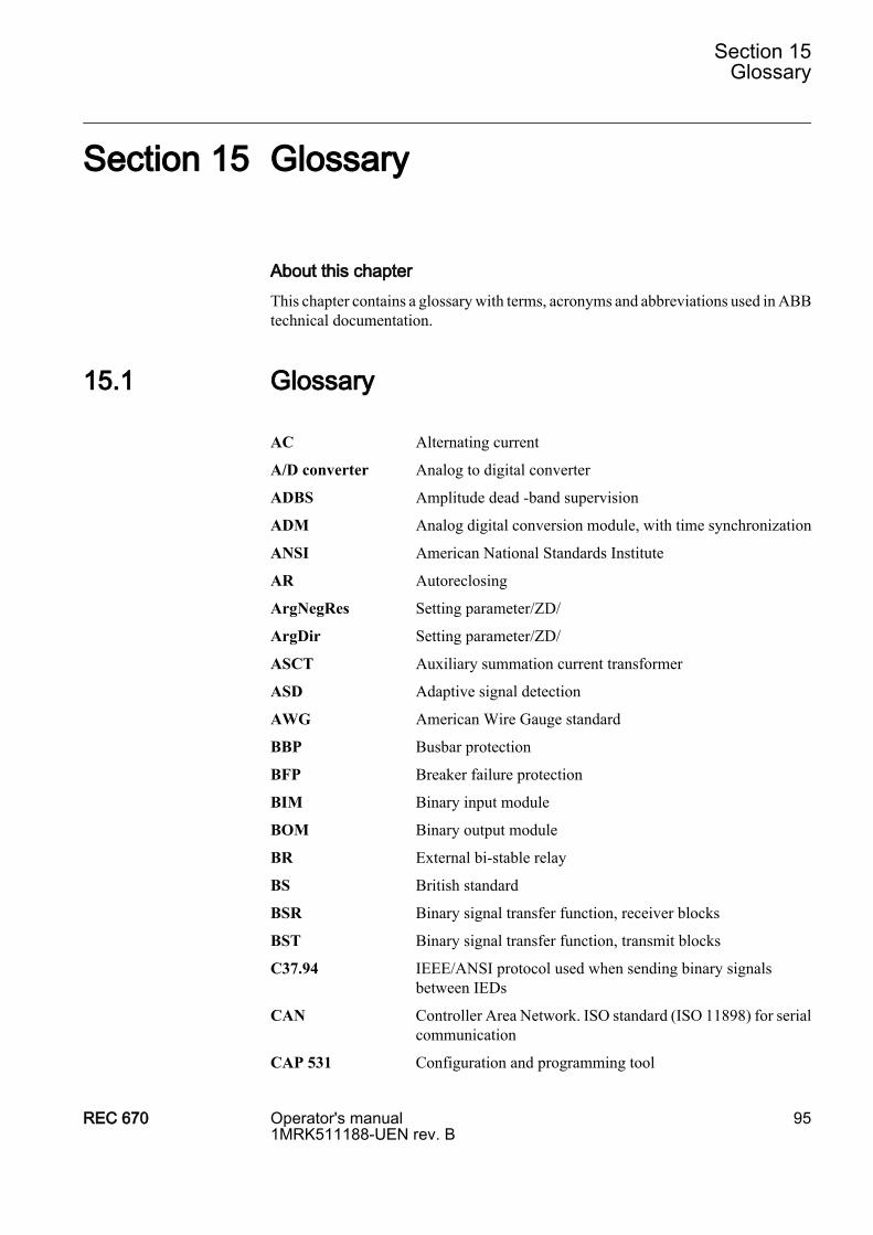
Section 15 Glossary
About this chapterThis chapter contains a glossary with terms, acronyms and abbreviations used in ABBtechnical documentation.
15.1 Glossary
AC Alternating current
A/D converter Analog to digital converter
ADBS Amplitude dead -band supervision
ADM Analog digital conversion module, with time synchronization
ANSI American National Standards Institute
AR Autoreclosing
ArgNegRes Setting parameter/ZD/
ArgDir Setting parameter/ZD/
ASCT Auxiliary summation current transformer
ASD Adaptive signal detection
AWG American Wire Gauge standard
BBP Busbar protection
BFP Breaker failure protection
BIM Binary input module
BOM Binary output module
BR External bi-stable relay
BS British standard
BSR Binary signal transfer function, receiver blocks
BST Binary signal transfer function, transmit blocks
C37.94 IEEE/ANSI protocol used when sending binary signalsbetween IEDs
CAN Controller Area Network. ISO standard (ISO 11898) for serialcommunication
CAP 531 Configuration and programming tool
Section 15Glossary
REC 670 Operator's manual1MRK511188-UEN rev. B
95
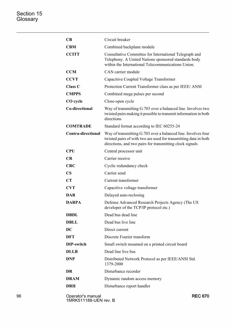
CB Circuit breaker
CBM Combined backplane module
CCITT Consultative Committee for International Telegraph andTelephony. A United Nations sponsored standards bodywithin the International Telecommunications Union.
CCM CAN carrier module
CCVT Capacitive Coupled Voltage Transformer
Class C Protection Current Transformer class as per IEEE/ ANSI
CMPPS Combined mega pulses per second
CO cycle Close-open cycle
Co-directional Way of transmitting G.703 over a balanced line. Involves twotwisted pairs making it possible to transmit information in bothdirections
COMTRADE Standard format according to IEC 60255-24
Contra-directional Way of transmitting G.703 over a balanced line. Involves fourtwisted pairs of with two are used for transmitting data in bothdirections, and two pairs for transmitting clock signals
CPU Central processor unit
CR Carrier receive
CRC Cyclic redundancy check
CS Carrier send
CT Current transformer
CVT Capacitive voltage transformer
DAR Delayed auto-reclosing
DARPA Defense Advanced Research Projects Agency (The USdeveloper of the TCP/IP protocol etc.)
DBDL Dead bus dead line
DBLL Dead bus live line
DC Direct current
DFT Discrete Fourier transform
DIP-switch Small switch mounted on a printed circuit board
DLLB Dead line live bus
DNP Distributed Network Protocol as per IEEE/ANSI Std.1379-2000
DR Disturbance recorder
DRAM Dynamic random access memory
DRH Disturbance report handler
Section 15Glossary
96 Operator's manual1MRK511188-UEN rev. B
REC 670
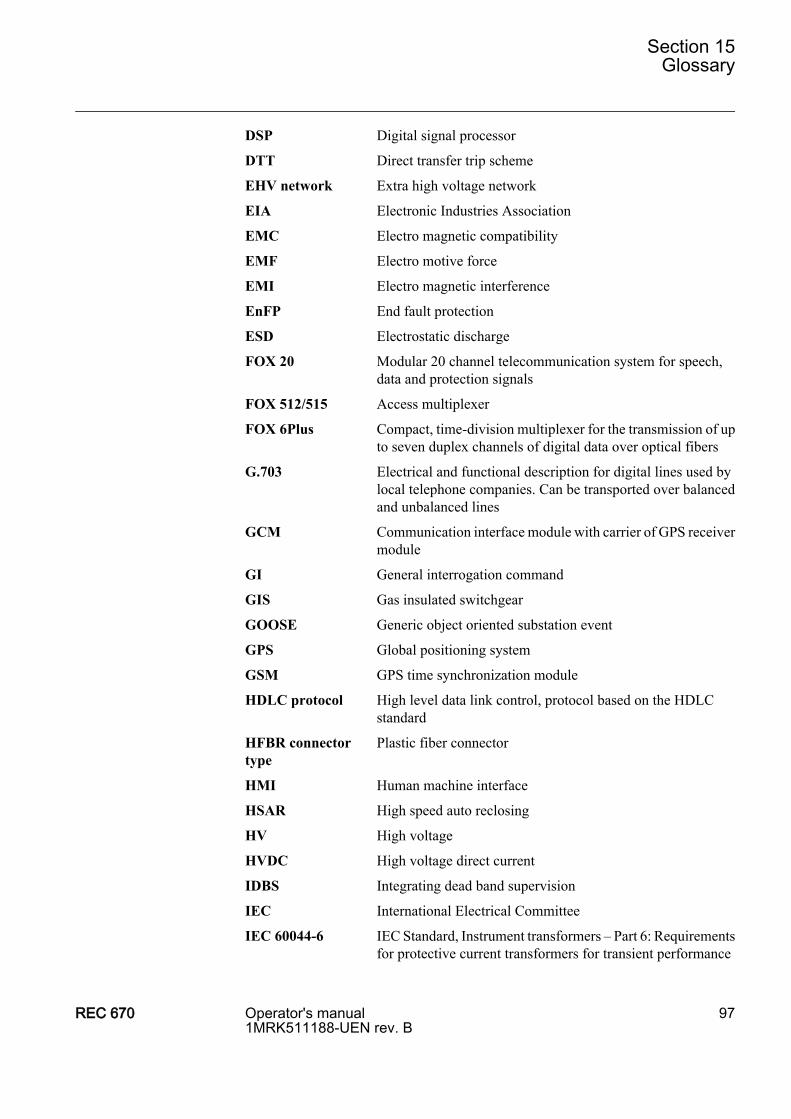
DSP Digital signal processor
DTT Direct transfer trip scheme
EHV network Extra high voltage network
EIA Electronic Industries Association
EMC Electro magnetic compatibility
EMF Electro motive force
EMI Electro magnetic interference
EnFP End fault protection
ESD Electrostatic discharge
FOX 20 Modular 20 channel telecommunication system for speech,data and protection signals
FOX 512/515 Access multiplexer
FOX 6Plus Compact, time-division multiplexer for the transmission of upto seven duplex channels of digital data over optical fibers
G.703 Electrical and functional description for digital lines used bylocal telephone companies. Can be transported over balancedand unbalanced lines
GCM Communication interface module with carrier of GPS receivermodule
GI General interrogation command
GIS Gas insulated switchgear
GOOSE Generic object oriented substation event
GPS Global positioning system
GSM GPS time synchronization module
HDLC protocol High level data link control, protocol based on the HDLCstandard
HFBR connectortype
Plastic fiber connector
HMI Human machine interface
HSAR High speed auto reclosing
HV High voltage
HVDC High voltage direct current
IDBS Integrating dead band supervision
IEC International Electrical Committee
IEC 60044-6 IEC Standard, Instrument transformers – Part 6: Requirementsfor protective current transformers for transient performance
Section 15Glossary
REC 670 Operator's manual1MRK511188-UEN rev. B
97
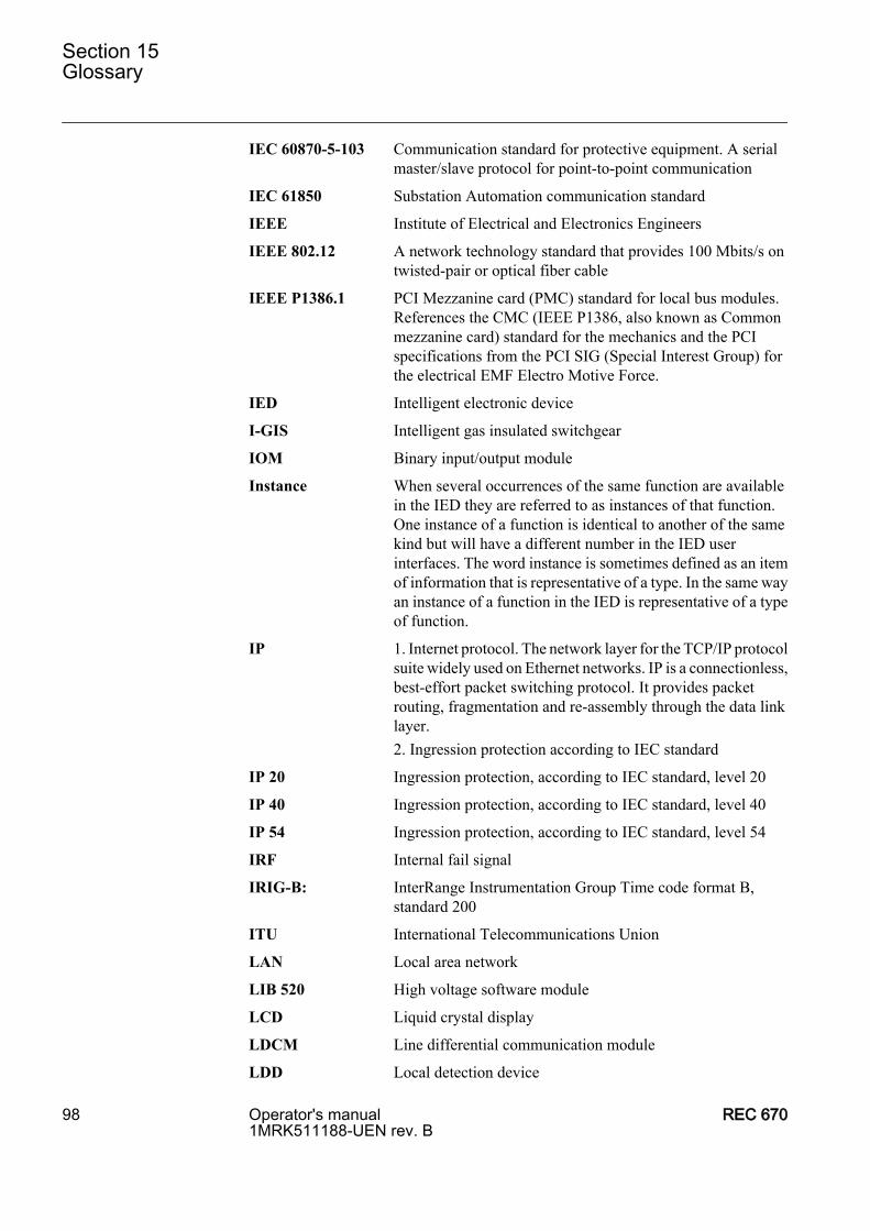
IEC 60870-5-103 Communication standard for protective equipment. A serialmaster/slave protocol for point-to-point communication
IEC 61850 Substation Automation communication standard
IEEE Institute of Electrical and Electronics Engineers
IEEE 802.12 A network technology standard that provides 100 Mbits/s ontwisted-pair or optical fiber cable
IEEE P1386.1 PCI Mezzanine card (PMC) standard for local bus modules.References the CMC (IEEE P1386, also known as Commonmezzanine card) standard for the mechanics and the PCIspecifications from the PCI SIG (Special Interest Group) forthe electrical EMF Electro Motive Force.
IED Intelligent electronic device
I-GIS Intelligent gas insulated switchgear
IOM Binary input/output module
Instance When several occurrences of the same function are availablein the IED they are referred to as instances of that function.One instance of a function is identical to another of the samekind but will have a different number in the IED userinterfaces. The word instance is sometimes defined as an itemof information that is representative of a type. In the same wayan instance of a function in the IED is representative of a typeof function.
IP 1. Internet protocol. The network layer for the TCP/IP protocolsuite widely used on Ethernet networks. IP is a connectionless,best-effort packet switching protocol. It provides packetrouting, fragmentation and re-assembly through the data linklayer.2. Ingression protection according to IEC standard
IP 20 Ingression protection, according to IEC standard, level 20
IP 40 Ingression protection, according to IEC standard, level 40
IP 54 Ingression protection, according to IEC standard, level 54
IRF Internal fail signal
IRIG-B: InterRange Instrumentation Group Time code format B,standard 200
ITU International Telecommunications Union
LAN Local area network
LIB 520 High voltage software module
LCD Liquid crystal display
LDCM Line differential communication module
LDD Local detection device
Section 15Glossary
98 Operator's manual1MRK511188-UEN rev. B
REC 670
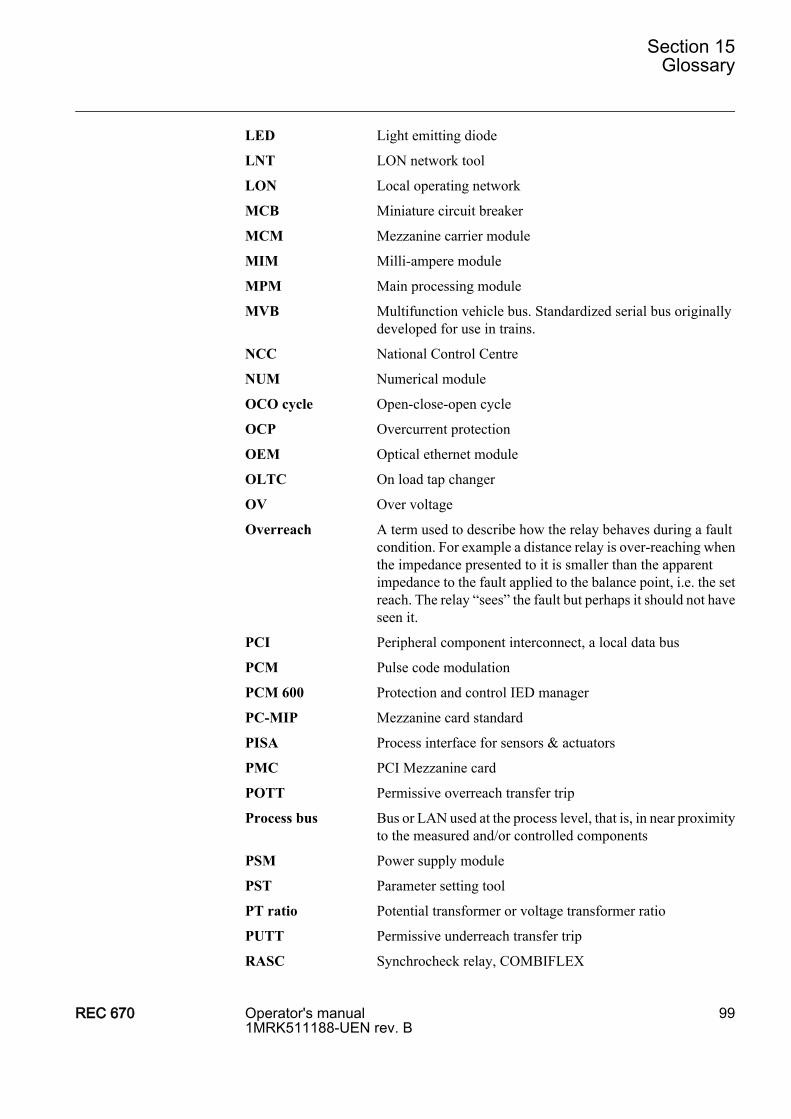
LED Light emitting diode
LNT LON network tool
LON Local operating network
MCB Miniature circuit breaker
MCM Mezzanine carrier module
MIM Milli-ampere module
MPM Main processing module
MVB Multifunction vehicle bus. Standardized serial bus originallydeveloped for use in trains.
NCC National Control Centre
NUM Numerical module
OCO cycle Open-close-open cycle
OCP Overcurrent protection
OEM Optical ethernet module
OLTC On load tap changer
OV Over voltage
Overreach A term used to describe how the relay behaves during a faultcondition. For example a distance relay is over-reaching whenthe impedance presented to it is smaller than the apparentimpedance to the fault applied to the balance point, i.e. the setreach. The relay “sees” the fault but perhaps it should not haveseen it.
PCI Peripheral component interconnect, a local data bus
PCM Pulse code modulation
PCM 600 Protection and control IED manager
PC-MIP Mezzanine card standard
PISA Process interface for sensors & actuators
PMC PCI Mezzanine card
POTT Permissive overreach transfer trip
Process bus Bus or LAN used at the process level, that is, in near proximityto the measured and/or controlled components
PSM Power supply module
PST Parameter setting tool
PT ratio Potential transformer or voltage transformer ratio
PUTT Permissive underreach transfer trip
RASC Synchrocheck relay, COMBIFLEX
Section 15Glossary
REC 670 Operator's manual1MRK511188-UEN rev. B
99

RCA Relay characteristic angle
REVAL Evaluation software
RFPP Resistance for phase-to-phase faults
RFPE Resistance for phase-to-earth faults
RISC Reduced instruction set computer
RMS value Root mean square value
RS422 A balanced serial interface for the transmission of digital datain point-to-point connections
RS485 Serial link according to EIA standard RS485
RTC Real time clock
RTU Remote terminal unit
SA Substation Automation
SC Switch or push-button to close
SCS Station control system
SCT System configuration tool according to standard IEC 61850
SLM Serial communication module. Used for SPA/LON/IECcommunication.
SMA connector Subminiature version A, A threaded connector with constantimpedance.
SMS Station monitoring system
SNTP Simple network time protocol – is used to synchronizecomputer clocks on local area networks. This reduces therequirement to have accurate hardware clocks in everyembedded system in a network. Each embedded node caninstead synchronize with a remote clock, providing therequired accuracy.
SPA Strömberg protection acquisition, a serial master/slaveprotocol for point-to-point communication
SRY Switch for CB ready condition
ST Switch or push-button to trip
Starpoint Neutral point of transformer or generator
SVC Static VAr compensation
TC Trip coil
TCS Trip circuit supervision
TCP Transmission control protocol. The most common transportlayer protocol used on Ethernet and the Internet.
TCP/IP Transmission control protocol over Internet Protocol. The defacto standard Ethernet protocols incorporated into 4.2BSD
Section 15Glossary
100 Operator's manual1MRK511188-UEN rev. B
REC 670
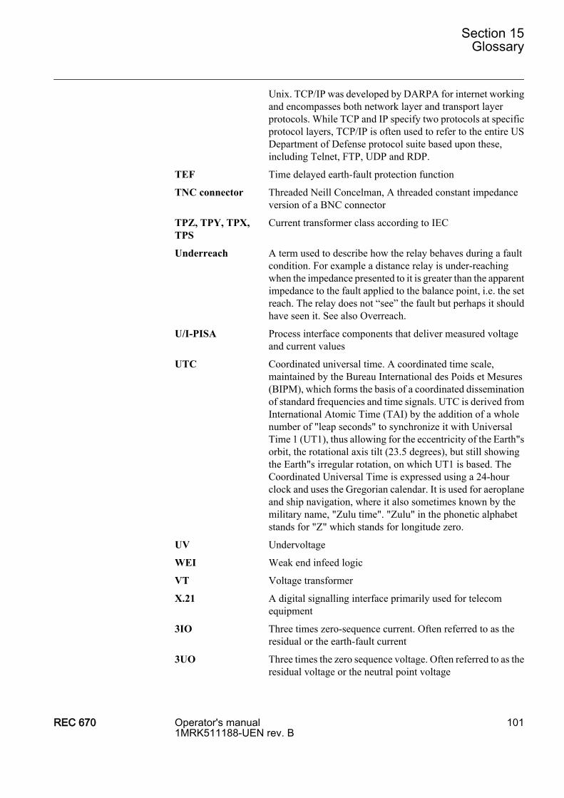
Unix. TCP/IP was developed by DARPA for internet workingand encompasses both network layer and transport layerprotocols. While TCP and IP specify two protocols at specificprotocol layers, TCP/IP is often used to refer to the entire USDepartment of Defense protocol suite based upon these,including Telnet, FTP, UDP and RDP.
TEF Time delayed earth-fault protection function
TNC connector Threaded Neill Concelman, A threaded constant impedanceversion of a BNC connector
TPZ, TPY, TPX,TPS
Current transformer class according to IEC
Underreach A term used to describe how the relay behaves during a faultcondition. For example a distance relay is under-reachingwhen the impedance presented to it is greater than the apparentimpedance to the fault applied to the balance point, i.e. the setreach. The relay does not “see” the fault but perhaps it shouldhave seen it. See also Overreach.
U/I-PISA Process interface components that deliver measured voltageand current values
UTC Coordinated universal time. A coordinated time scale,maintained by the Bureau International des Poids et Mesures(BIPM), which forms the basis of a coordinated disseminationof standard frequencies and time signals. UTC is derived fromInternational Atomic Time (TAI) by the addition of a wholenumber of "leap seconds" to synchronize it with UniversalTime 1 (UT1), thus allowing for the eccentricity of the Earth"sorbit, the rotational axis tilt (23.5 degrees), but still showingthe Earth"s irregular rotation, on which UT1 is based. TheCoordinated Universal Time is expressed using a 24-hourclock and uses the Gregorian calendar. It is used for aeroplaneand ship navigation, where it also sometimes known by themilitary name, "Zulu time". "Zulu" in the phonetic alphabetstands for "Z" which stands for longitude zero.
UV Undervoltage
WEI Weak end infeed logic
VT Voltage transformer
X.21 A digital signalling interface primarily used for telecomequipment
3IO Three times zero-sequence current. Often referred to as theresidual or the earth-fault current
3UO Three times the zero sequence voltage. Often referred to as theresidual voltage or the neutral point voltage
Section 15Glossary
REC 670 Operator's manual1MRK511188-UEN rev. B
101

102