receive antennas: beverages and beyondthe wire, in the same direction as the radio waves. the lack...
TRANSCRIPT
Receive Antennas:Beverages and Beyond
Silvercreek Amateur Radio AssociationJeff Royer W8TB

No, not those beverages…
Let’s discuss beverages…
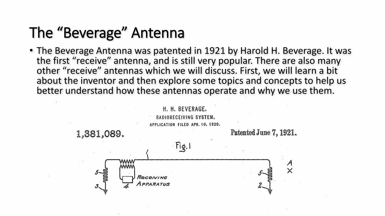
The “Beverage” Antenna• The Beverage Antenna was patented in 1921 by Harold H. Beverage. It was
the first “receive” antenna, and is still very popular. There are also many other “receive” antennas which we will discuss. First, we will learn a bit about the inventor and then explore some topics and concepts to help us better understand how these antennas operate and why we use them.
Origins of the receive antenna
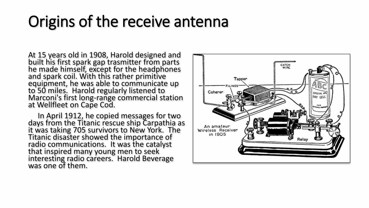
At 15 years old in 1908, Harold designed and built his first spark gap trasmitter from parts he made himself, except for the headphones and spark coil. With this rather primitive equipment, he was able to communicate up to 50 miles. Harold regularly listened to Marconi's first long-range commercial station at Wellfleet on Cape Cod.
In April 1912, he copied messages for two days from the Titanic rescue ship Carpathia as it was taking 705 survivors to New York. The Titanic disaster showed the importance of radio communications. It was the catalyst that inspired many young men to seek interesting radio careers. Harold Beverage was one of them.
Origins of the receive antenna (Early Years)
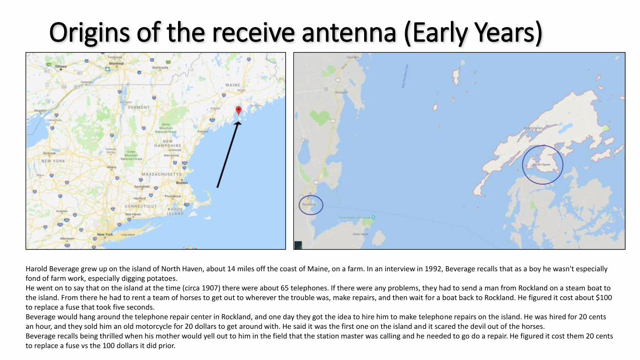
Harold Beverage grew up on the island of North Haven, about 14 miles off the coast of Maine, on a farm. In an interview in 1992, Beverage recalls that as a boy he wasn't especially fond of farm work, especially digging potatoes. He went on to say that on the island at the time (circa 1907) there were about 65 telephones. If there were any problems, they had to send a man from Rockland on a steam boat to the island. From there he had to rent a team of horses to get out to wherever the trouble was, make repairs, and then wait for a boat back to Rockland. He figured it cost about $100 to replace a fuse that took five seconds.Beverage would hang around the telephone repair center in Rockland, and one day they got the idea to hire him to make telephone repairs on the island. He was hired for 20 cents an hour, and they sold him an old motorcycle for 20 dollars to get around with. He said it was the first one on the island and it scared the devil out of the horses.Beverage recalls being thrilled when his mother would yell out to him in the field that the station master was calling and he needed to go do a repair. He figured it cost them 20 cents to replace a fuse vs the 100 dollars it did prior.
Origins of the receive antenna
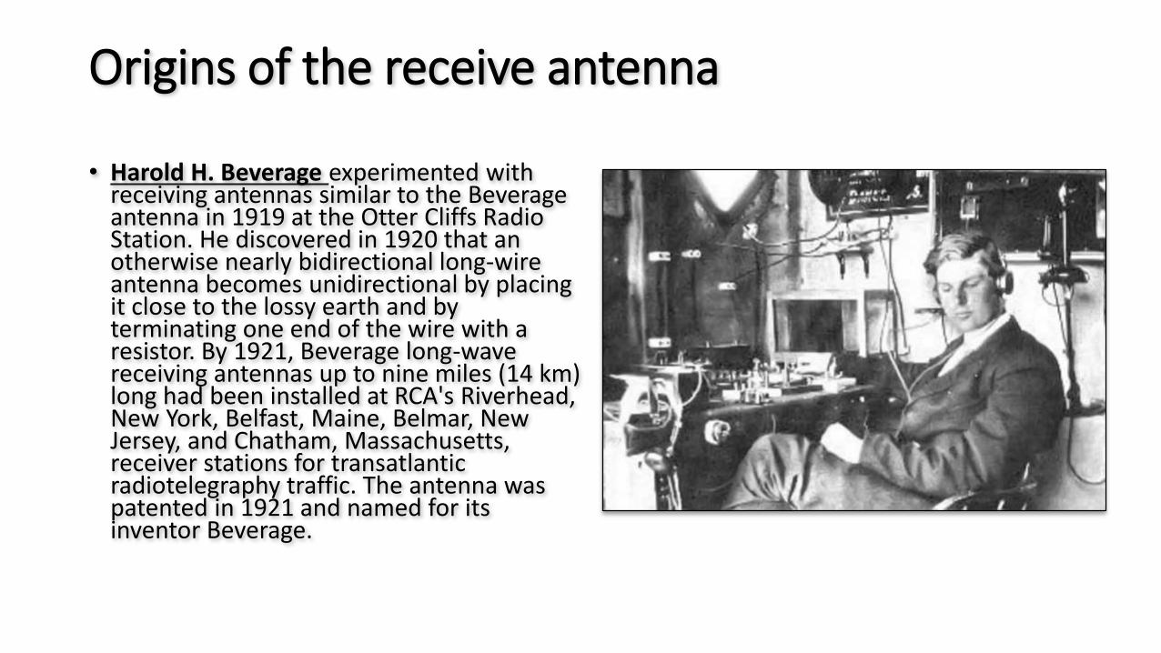
• Harold H. Beverage experimented with receiving antennas similar to the Beverage antenna in 1919 at the Otter Cliffs Radio Station. He discovered in 1920 that an otherwise nearly bidirectional long-wire antenna becomes unidirectional by placing it close to the lossy earth and by terminating one end of the wire with a resistor. By 1921, Beverage long-wave receiving antennas up to nine miles (14 km) long had been installed at RCA's Riverhead, New York, Belfast, Maine, Belmar, New Jersey, and Chatham, Massachusetts, receiver stations for transatlantic radiotelegraphy traffic. The antenna was patented in 1921 and named for its inventor Beverage.
Origins of the receive antenna
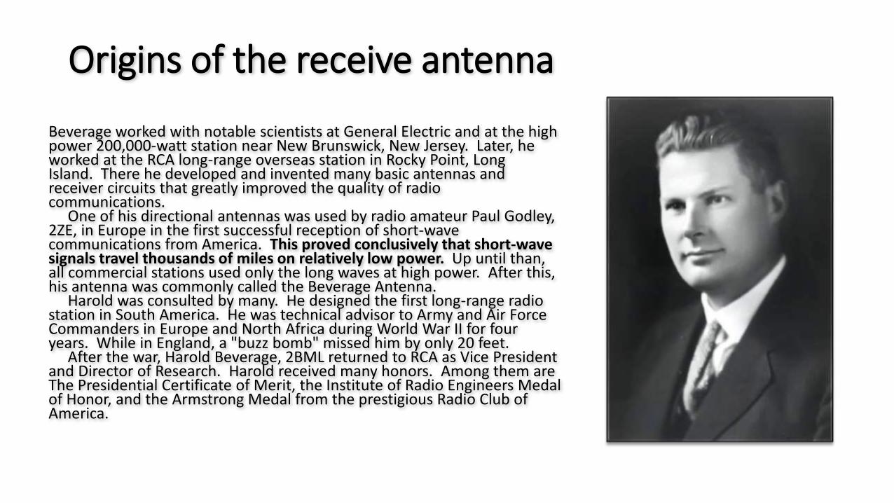
Beverage worked with notable scientists at General Electric and at the high power 200,000-watt station near New Brunswick, New Jersey. Later, he worked at the RCA long-range overseas station in Rocky Point, Long Island. There he developed and invented many basic antennas and receiver circuits that greatly improved the quality of radio communications.
One of his directional antennas was used by radio amateur Paul Godley, 2ZE, in Europe in the first successful reception of short-wave communications from America. This proved conclusively that short-wave signals travel thousands of miles on relatively low power. Up until than, all commercial stations used only the long waves at high power. After this, his antenna was commonly called the Beverage Antenna.
Harold was consulted by many. He designed the first long-range radio station in South America. He was technical advisor to Army and Air Force Commanders in Europe and North Africa during World War II for four years. While in England, a "buzz bomb" missed him by only 20 feet.
After the war, Harold Beverage, 2BML returned to RCA as Vice President and Director of Research. Harold received many honors. Among them are The Presidential Certificate of Merit, the Institute of Radio Engineers Medal of Honor, and the Armstrong Medal from the prestigious Radio Club of America.
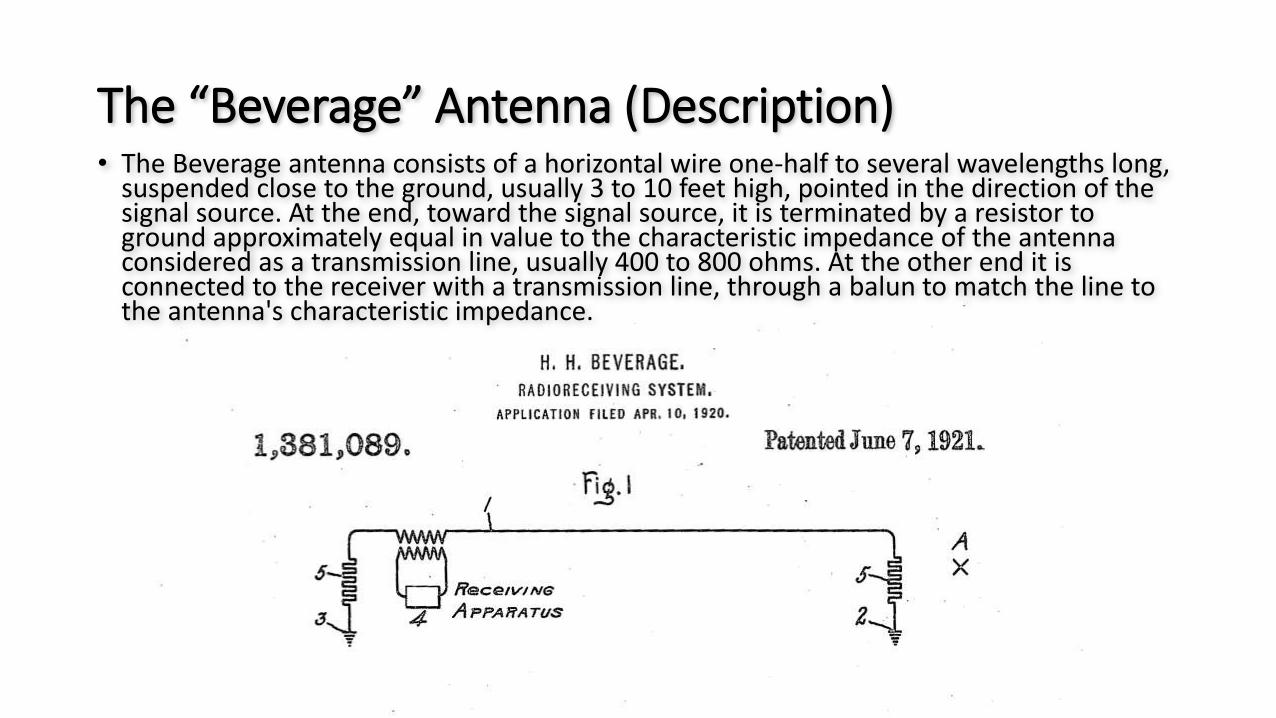
The “Beverage” Antenna (Description)• The Beverage antenna consists of a horizontal wire one-half to several wavelengths long,
suspended close to the ground, usually 3 to 10 feet high, pointed in the direction of the signal source. At the end, toward the signal source, it is terminated by a resistor to ground approximately equal in value to the characteristic impedance of the antenna considered as a transmission line, usually 400 to 800 ohms. At the other end it is connected to the receiver with a transmission line, through a balun to match the line to the antenna's characteristic impedance.
The “Beverage” Antenna (Traveling Wave)
• Unlike other wire antennas such as dipole or monopole antennas which act as resonators, with the radio currents traveling in both directions along the element, bouncing back and forth between the ends as standing waves, the Beverage antenna is a traveling wave antenna; the radio frequency current travels in one direction along the wire, in the same direction as the radio waves. The lack of resonance gives it a wider bandwidth than resonant antennas. It receives vertically polarized radio waves, but unlike other vertically polarized antennas it is suspended close to the ground, and requires some resistance in the ground to work.
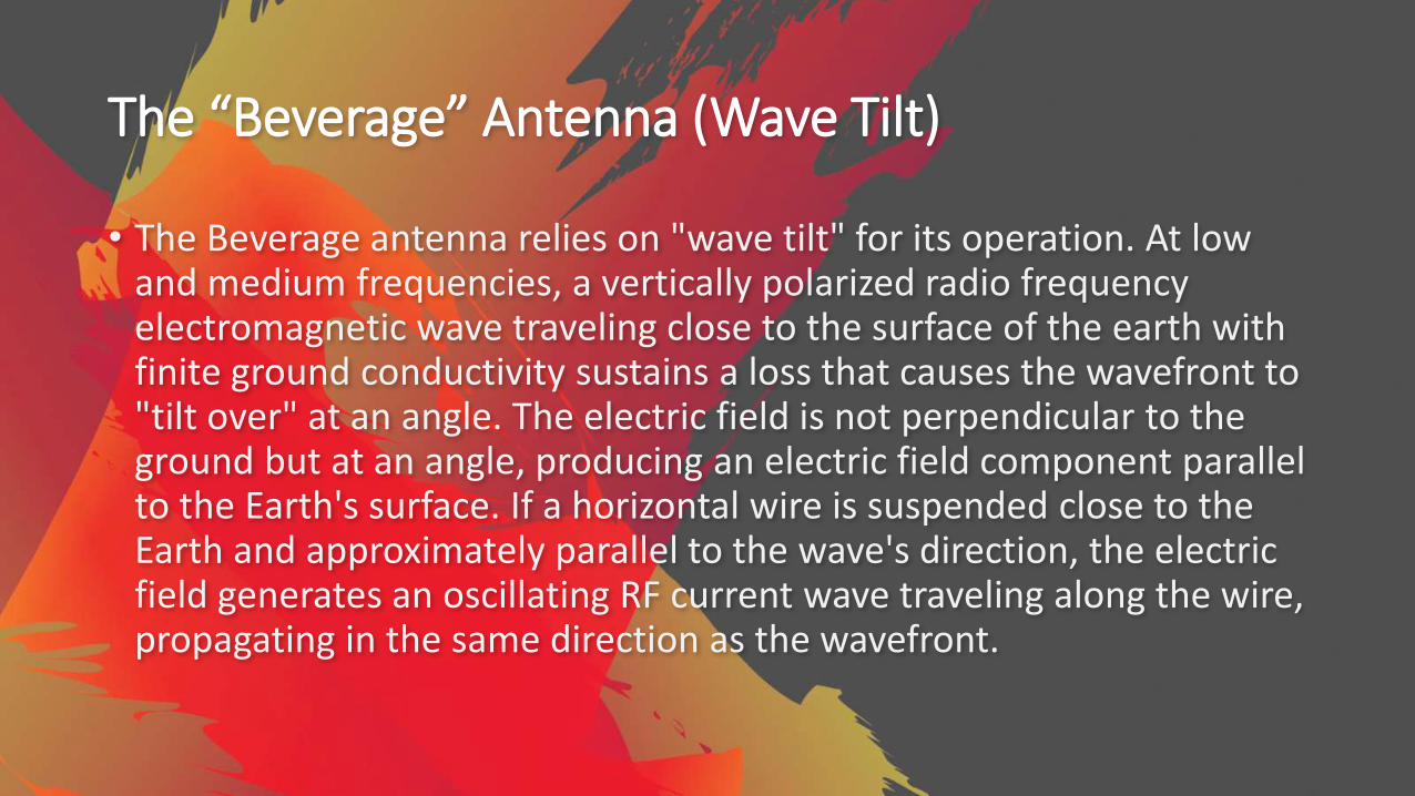
The “Beverage” Antenna (Wave Tilt)
• The Beverage antenna relies on "wave tilt" for its operation. At low and medium frequencies, a vertically polarized radio frequency electromagnetic wave traveling close to the surface of the earth with finite ground conductivity sustains a loss that causes the wavefront to "tilt over" at an angle. The electric field is not perpendicular to the ground but at an angle, producing an electric field component parallel to the Earth's surface. If a horizontal wire is suspended close to the Earth and approximately parallel to the wave's direction, the electric field generates an oscillating RF current wave traveling along the wire, propagating in the same direction as the wavefront.
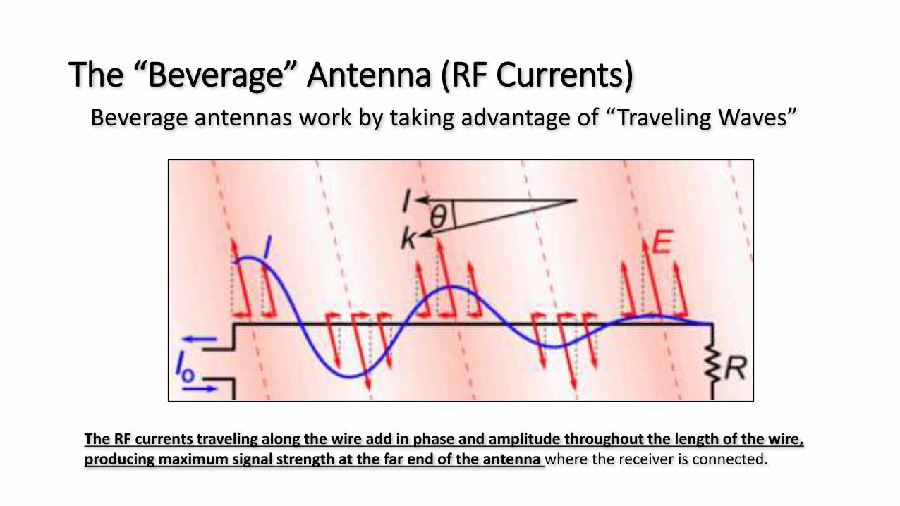
The “Beverage” Antenna (RF Currents)Beverage antennas work by taking advantage of “Traveling Waves”
The RF currents traveling along the wire add in phase and amplitude throughout the length of the wire, producing maximum signal strength at the far end of the antenna where the receiver is connected.
The “Beverage” Antenna (Reception Pattern)
• The antenna wire and the ground under it together can be thought of as a "leaky" transmission line which absorbs energy from the radio waves.
• The antenna has a unidirectional reception pattern, because RF signals arriving from the other direction, from the receiver end of the wire, induce currents propagating toward the terminated end, where they are absorbed by the terminating resistor.
Background Noise on HF
• The HF Radio Noise Environment• On HF (3 - 30 MHz), and MF (0.3 – 3 MHz), there will always be noise picked up by the antenna,
however well it is sited - this is called the ambient radio noise. This noise may be either man-made or natural, and unless the receiving antenna is extremely inefficient, will be much greater than the thermal noise generated in the front-end of the receiver. As frequencies rise into the VHF region, the natural noise decreases, until above about 100MHz the thermal noise in the receiver front-end becomes significant.
• Natural Noise• This is the 'bottom line' of the noise in any particular location. It comes mainly from noise from
atmospheric discharges which are always taking place somewhere in the world and are propagated by the ionosphere. There is also the noise coming from space usually called galactic or cosmic noise. Both these sources sound like white noise There may also be local atmospheric static but this is usually not a serious problem.
• The Ambient Noise Floor• Traditionally the ambient noise floor has been defined as the noise which exists when specific local
sources of noise (sometimes called ‘incidental noise’) have been eliminated. If the ambient noise is observed on a horizontal dipole antenna situated in a residential area, a ‘floor’ will be seen consisting of the natural noise, plus an aggregate of distant man-made sources. This is usually fairly constant in any particular location and sounds like white noise with an added gritty component.
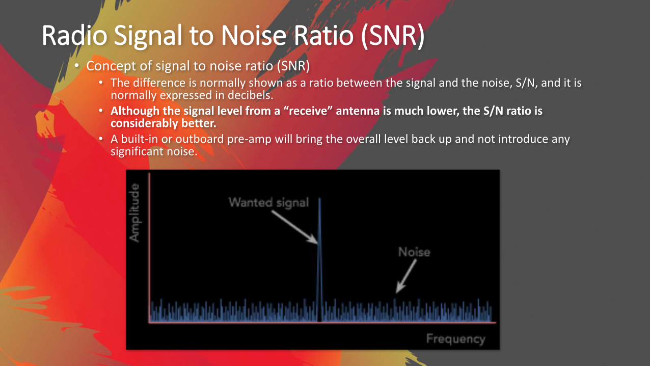
Radio Signal to Noise Ratio (SNR)• Concept of signal to noise ratio (SNR)
• The difference is normally shown as a ratio between the signal and the noise, S/N, and it is normally expressed in decibels.
• Although the signal level from a “receive” antenna is much lower, the S/N ratio is considerably better.
• A built-in or outboard pre-amp will bring the overall level back up and not introduce any significant noise.

Why would you use a receive antenna?
• The main reason to use receive antennas is for increased signal-to-noise, and increased directivity.
• Receive antennas exhibit much better performance than transmitting antennas, especially on 160 and 80 meters• Much lower cost• Greatly reduced footprint• Greatly reduced height (3 to 10 feet for beverages, 7 to 25 feet for verticals)• Good directivity on as little as 650 to 2500 square feet• Excellent directivity on less than an ¼ acre• Superb directivity on less than ¾ acre• Greatly reduced mutual coupling between individual verticals• Greatly reduced need for high efficiency matching and radial systems
• High performance arrays perform equivalent to a 5 element Yagi!
The “Beverage” Antenna (Gain and Directivity)
• While Beverage antennas have excellent directivity, because they are close to lossy Earth, they do not produce absolute gain; their gain is typically from −20 to −10 dBi. This is rarely a problem, because the antenna is used at frequencies where there are high levels of atmospheric radio noise. At these frequencies the atmospheric noise, and not receiver noise, determines the signal-to-noise ratio, so an inefficient antenna can be used. The antenna is not used as a transmitting antenna since, to do so, would mean a large portion of the drive power is wasted in the terminating resistor.
• Directivity increases with the length of the antenna. While directivity begins to develop at a length of only ¼ wavelength, directivity becomes more significant at one wavelength and improves steadily until the antenna reaches a length of about two wavelengths. In Beverages longer than two wavelengths, directivity does not increase because the currents in the antenna cannot remain in phase with the radio wave.

Measuring the performance of a receive antennas (RDF) Receiving Directivity Factor
• Receive antenna performance is measured using (RDF) Receiving Directivity Factor.• Compares forward gain at the desired azimuth and elevation angle to average gain over the
entire hemisphere
• Assumes noise is equally distributed over the entire hemisphere, an invalid assumption for suburban and especially urban location where noise is more intensely concentrated on the horizon
• Assumes that the noise is in the far field of the antenna – more than 1000 feet away – where the antenna pattern is fully formed and the noise sources look more like point sources.
Measuring the performance of a receive antennas (Types and RDF) Standard
• Small Receiving Antennas (4-9 dB RDF)• 4 dB: 8 foot diameter “magnetic” loop• 5 dB: Single vertical antenna (short vertical or ¼ wavelength vertical)• 6 dB: 225 foot Beverage on Ground (BOG)• 6 dB: 250-400 foot Beverage• 7 dB: Unidirectional terminated loop
• Flag, Pennant, EWE, VE3DO
• 8 dB: Pair of 250-400 foot staggered Beverages• 8 dB: Close spaced arrays of two small terminated loops
• K9AY Array• Shared Apex Loop Array
• 9 dB: Two phased short verticals with 60-80 foot spacing• 9 dB: Triangle array of phased short verticals with 60-80 foot spacing
Measuring the performance of a receive antennas (Types and RDF) High Performance
• High Performance Receiving Antennas (10-14 dB RDF)• 10 dB: 500-600 foot Beverage • 11 dB: Two or three close spaced 500-600 foot Beverages, staggered 65 feet• 12 dB: 4 square array of short Hi-Z or passive verticals (80 x 80 feet)• 12 dB: 3 element YCCC tri-band array of short verticals (84 x 84 feet)• 12 dB: 5-square YCCC tri-band array of short verticals (84 x 84 feet)• 12 dB: 9-Circle YCCC tri-band array of short verticals (120 foot diameter)• 12 dB: Horizontal Waller Flag: 2 phased horizontal loops at least 100 feet high• 13 dB: BSEF array of four short verticals switchable in two directions (1/2 acre) • 13 dB: Hi-Z 8-circle array of short pre-amplified verticals (200 foot diameter)• 13 dB: 8-circle BSEF array of short passive verticals (350 foot diameter+radials)• 14 dB: Four broadside/end-fire 800 foot Beverages (800 feet x 330 feet)
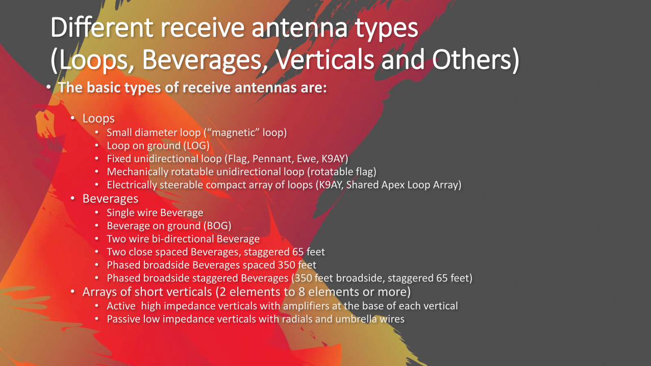
Different receive antenna types(Loops, Beverages, Verticals and Others)• The basic types of receive antennas are:
• Loops• Small diameter loop (“magnetic” loop)• Loop on ground (LOG)• Fixed unidirectional loop (Flag, Pennant, Ewe, K9AY)• Mechanically rotatable unidirectional loop (rotatable flag)• Electrically steerable compact array of loops (K9AY, Shared Apex Loop Array)
• Beverages• Single wire Beverage• Beverage on ground (BOG)• Two wire bi-directional Beverage• Two close spaced Beverages, staggered 65 feet• Phased broadside Beverages spaced 350 feet• Phased broadside staggered Beverages (350 feet broadside, staggered 65 feet)
• Arrays of short verticals (2 elements to 8 elements or more)• Active high impedance verticals with amplifiers at the base of each vertical• Passive low impedance verticals with radials and umbrella wires
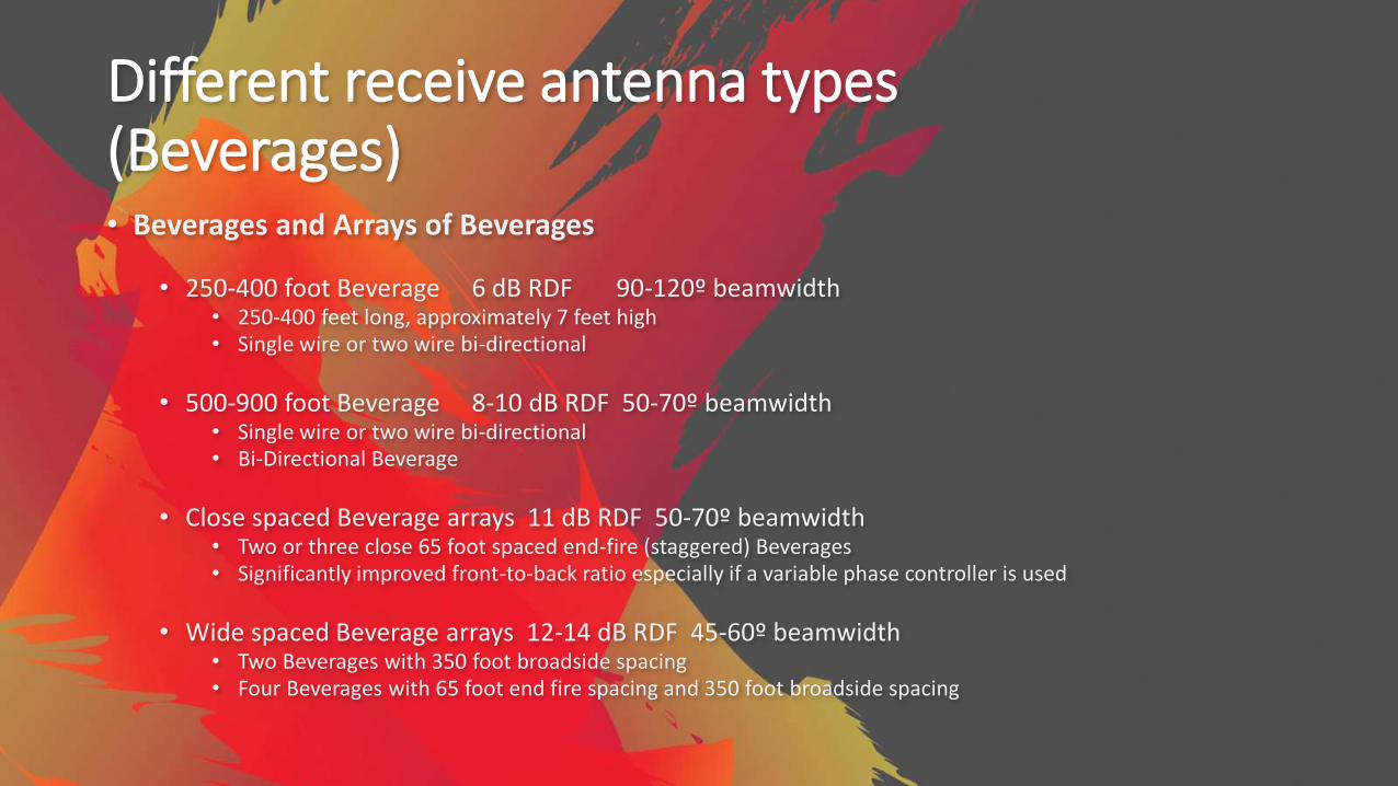
Different receive antenna types(Beverages)• Beverages and Arrays of Beverages
• 250-400 foot Beverage 6 dB RDF 90-120º beamwidth• 250-400 feet long, approximately 7 feet high• Single wire or two wire bi-directional
• 500-900 foot Beverage 8-10 dB RDF 50-70º beamwidth• Single wire or two wire bi-directional• Bi-Directional Beverage
• Close spaced Beverage arrays 11 dB RDF 50-70º beamwidth• Two or three close 65 foot spaced end-fire (staggered) Beverages• Significantly improved front-to-back ratio especially if a variable phase controller is used
• Wide spaced Beverage arrays 12-14 dB RDF 45-60º beamwidth• Two Beverages with 350 foot broadside spacing• Four Beverages with 65 foot end fire spacing and 350 foot broadside spacing
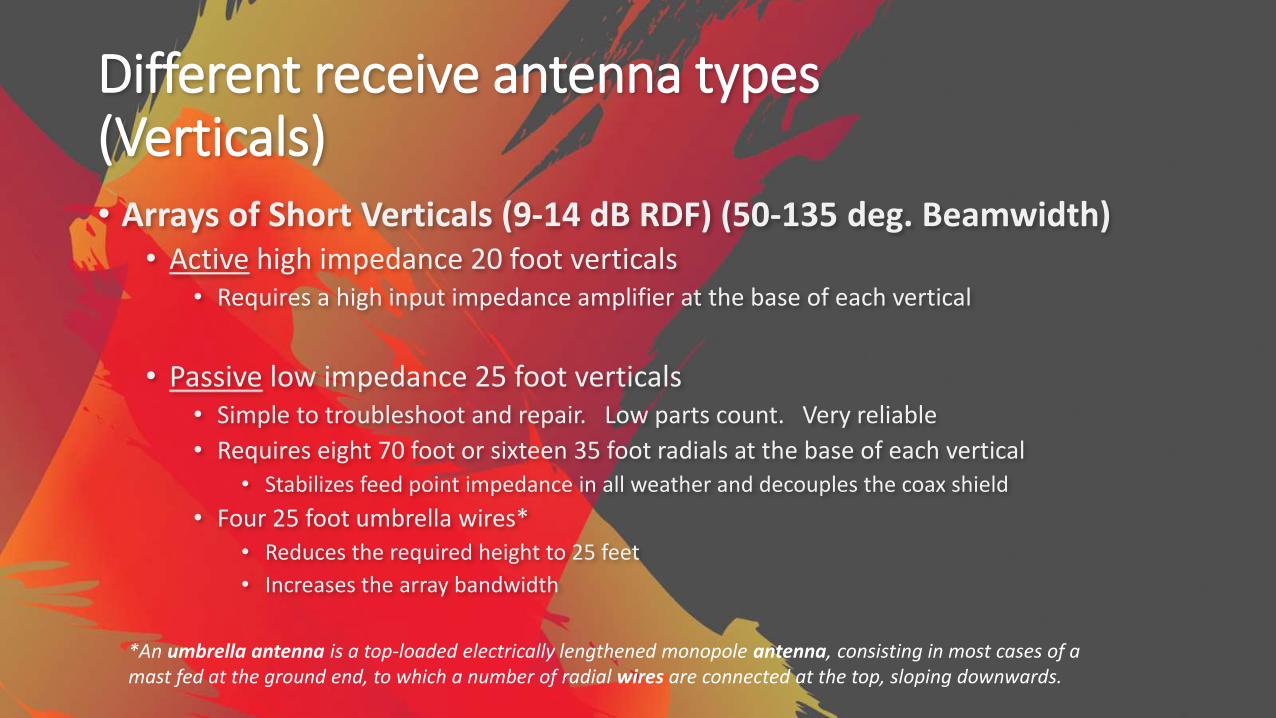
Different receive antenna types(Verticals)• Arrays of Short Verticals (9-14 dB RDF) (50-135 deg. Beamwidth)
• Active high impedance 20 foot verticals • Requires a high input impedance amplifier at the base of each vertical
• Passive low impedance 25 foot verticals • Simple to troubleshoot and repair. Low parts count. Very reliable
• Requires eight 70 foot or sixteen 35 foot radials at the base of each vertical • Stabilizes feed point impedance in all weather and decouples the coax shield
• Four 25 foot umbrella wires*• Reduces the required height to 25 feet
• Increases the array bandwidth
*An umbrella antenna is a top-loaded electrically lengthened monopole antenna, consisting in most cases of a mast fed at the ground end, to which a number of radial wires are connected at the top, sloping downwards.
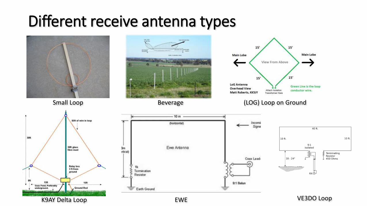
Different receive antenna types
Small Loop Beverage (LOG) Loop on Ground
K9AY Delta Loop EWE VE3DO Loop

Different receive antenna types(Loop)
• Small Diameter Loop• Inexpensive and very easy to build and use
• 24-36 inch diameter
• Bi-Directional 160 degree 3 dB beamwidth
• 4 dB RDF

Different receive antenna types(Loop)
• Two K9AY Loops• 25x25 foot square footprint
• Switchable in four directions
• 120 degree 3 dB beamwidth
• 7 dB RDF
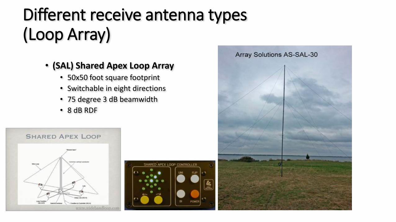
Different receive antenna types(Loop Array)
• (SAL) Shared Apex Loop Array• 50x50 foot square footprint
• Switchable in eight directions
• 75 degree 3 dB beamwidth
• 8 dB RDF
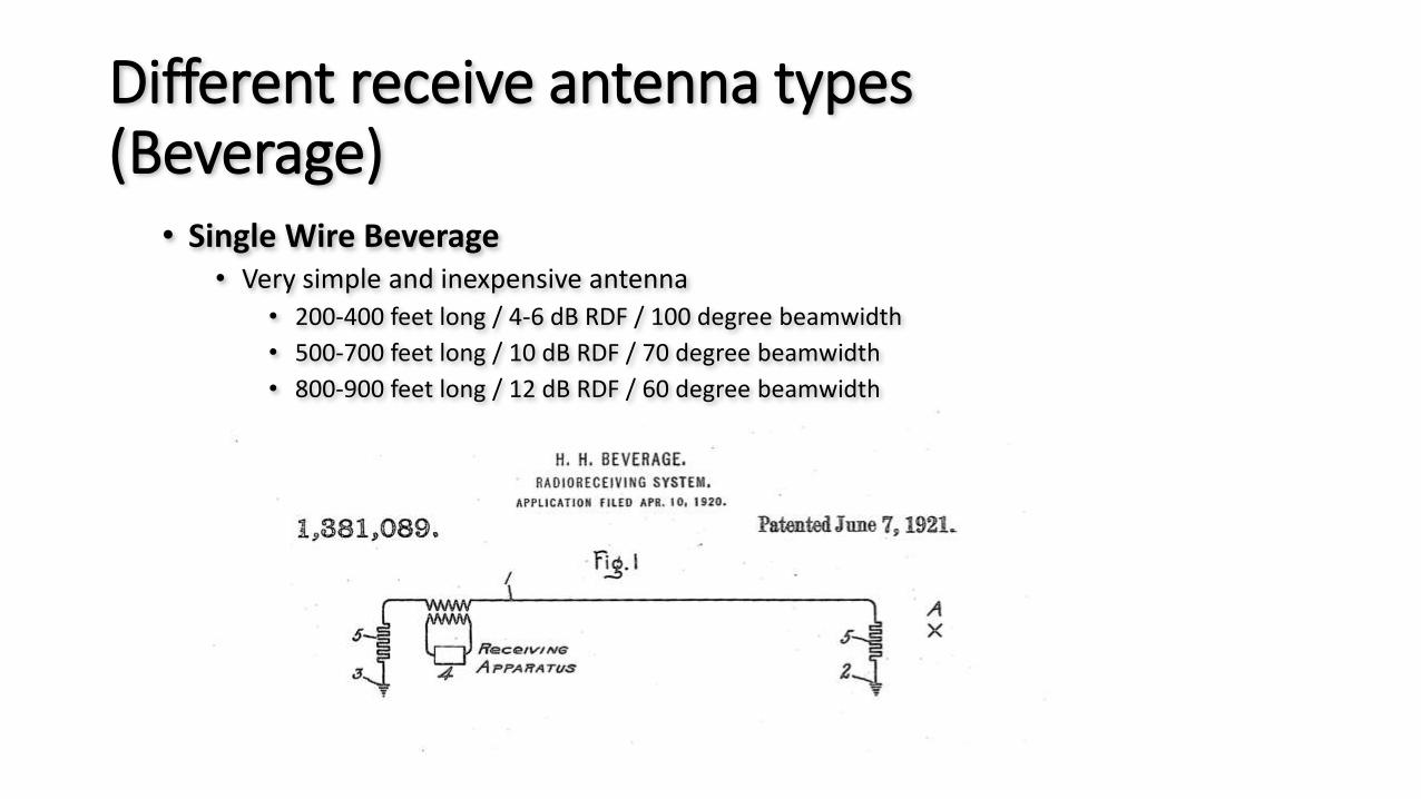
Different receive antenna types(Beverage)
• Single Wire Beverage• Very simple and inexpensive antenna
• 200-400 feet long / 4-6 dB RDF / 100 degree beamwidth
• 500-700 feet long / 10 dB RDF / 70 degree beamwidth
• 800-900 feet long / 12 dB RDF / 60 degree beamwidth
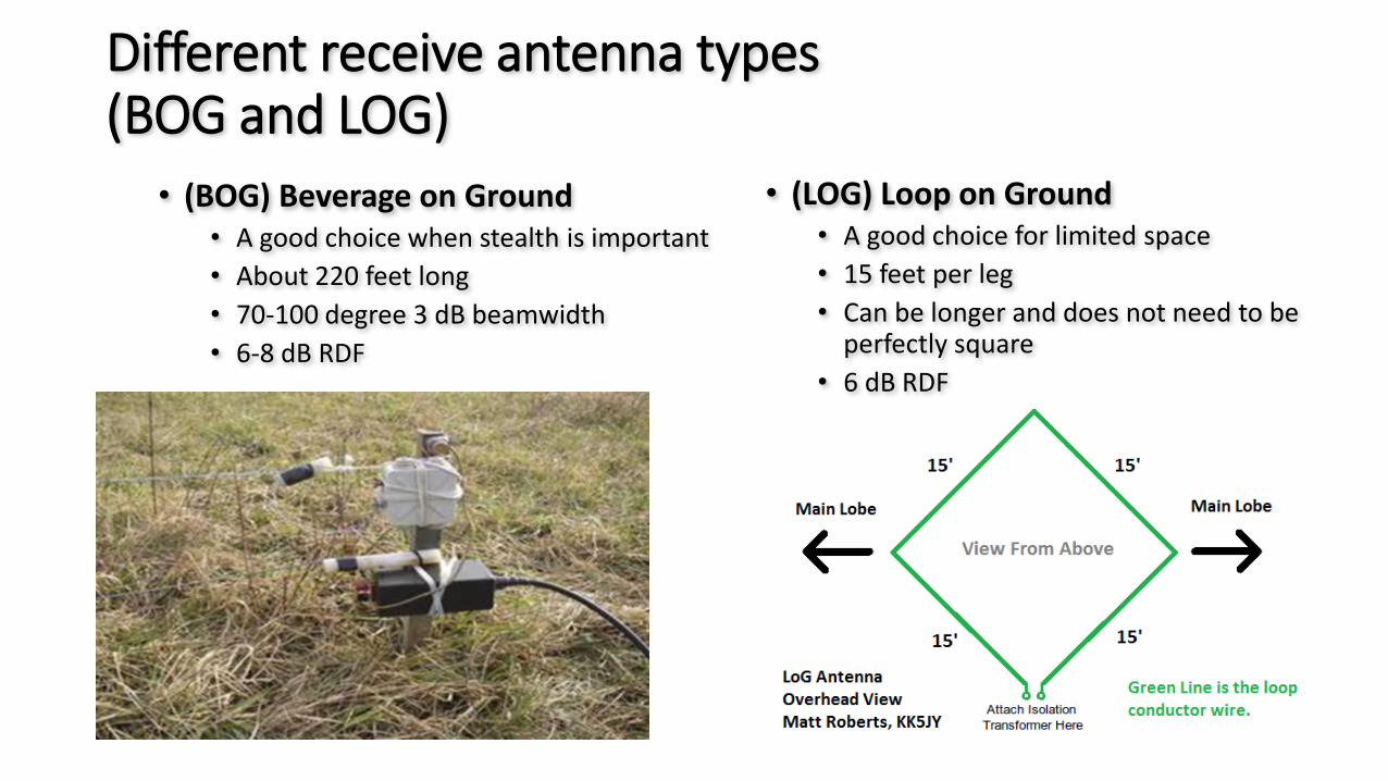
Different receive antenna types(BOG and LOG)
• (BOG) Beverage on Ground• A good choice when stealth is important
• About 220 feet long
• 70-100 degree 3 dB beamwidth
• 6-8 dB RDF
• (LOG) Loop on Ground• A good choice for limited space
• 15 feet per leg
• Can be longer and does not need to be perfectly square
• 6 dB RDF
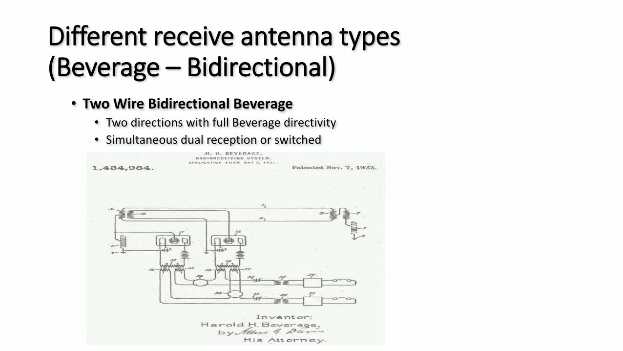
Different receive antenna types(Beverage – Bidirectional)
• Two Wire Bidirectional Beverage• Two directions with full Beverage directivity
• Simultaneous dual reception or switched
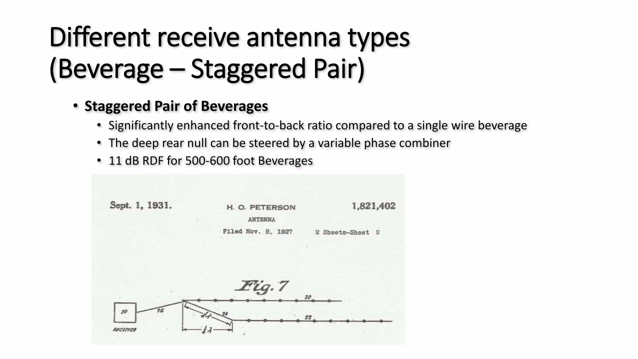
Different receive antenna types(Beverage – Staggered Pair)
• Staggered Pair of Beverages• Significantly enhanced front-to-back ratio compared to a single wire beverage
• The deep rear null can be steered by a variable phase combiner
• 11 dB RDF for 500-600 foot Beverages
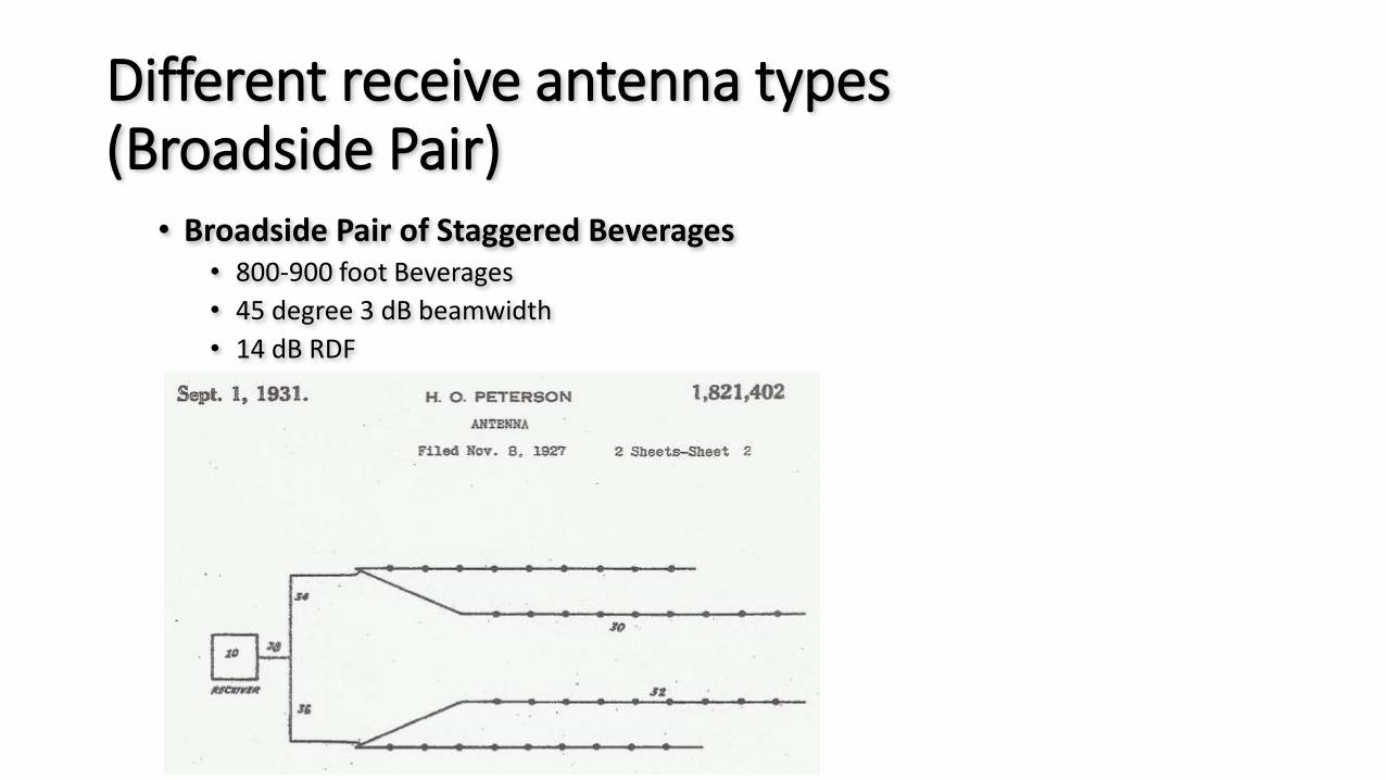
Different receive antenna types(Broadside Pair)
• Broadside Pair of Staggered Beverages• 800-900 foot Beverages
• 45 degree 3 dB beamwidth
• 14 dB RDF

Different receive antenna types(Vertical – Short Phased)
• Phased Short Verticals• (Two or more Low Impedance 25 foot verticals)
• Requires eight 70 foot radials per vertical • Or sixteen 35 foot radials• Laid on the ground or shallow buried
• Requires four 25 foot umbrella wires per vertical• Or four 35 foot verticals with no umbrella wires
• As little a 65 foot element spacing• Closer spacing is impractical for optimum performance
• No amplifiers are needed at the base of each vertical• Switchable in multiple directions• Tolerant of nearby objects• Easy to homebrew your own antenna
• Large arrays are very tolerant of moderate amplitude and phase errors
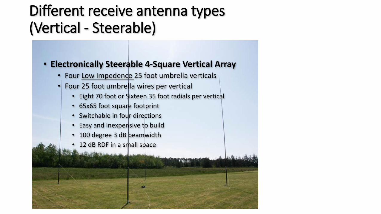
Different receive antenna types(Vertical - Steerable)
• Electronically Steerable 4-Square Vertical Array• Four Low Impedence 25 foot umbrella verticals
• Four 25 foot umbrella wires per vertical• Eight 70 foot or Sixteen 35 foot radials per vertical
• 65x65 foot square footprint
• Switchable in four directions
• Easy and Inexpensive to build
• 100 degree 3 dB beamwidth
• 12 dB RDF in a small space
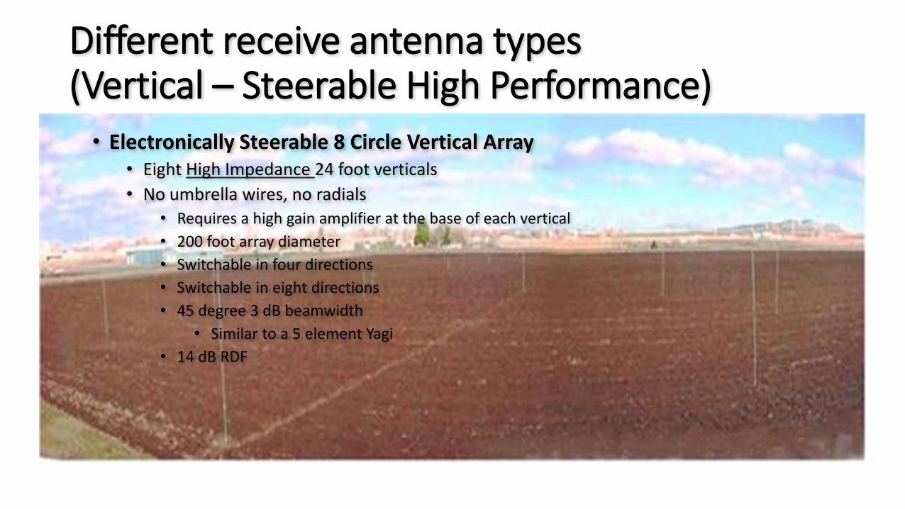
Different receive antenna types(Vertical – Steerable High Performance)• Electronically Steerable 8 Circle Vertical Array
• Eight High Impedance 24 foot verticals
• No umbrella wires, no radials• Requires a high gain amplifier at the base of each vertical
• 200 foot array diameter
• Switchable in four directions
• Switchable in eight directions
• 45 degree 3 dB beamwidth
• Similar to a 5 element Yagi
• 14 dB RDF
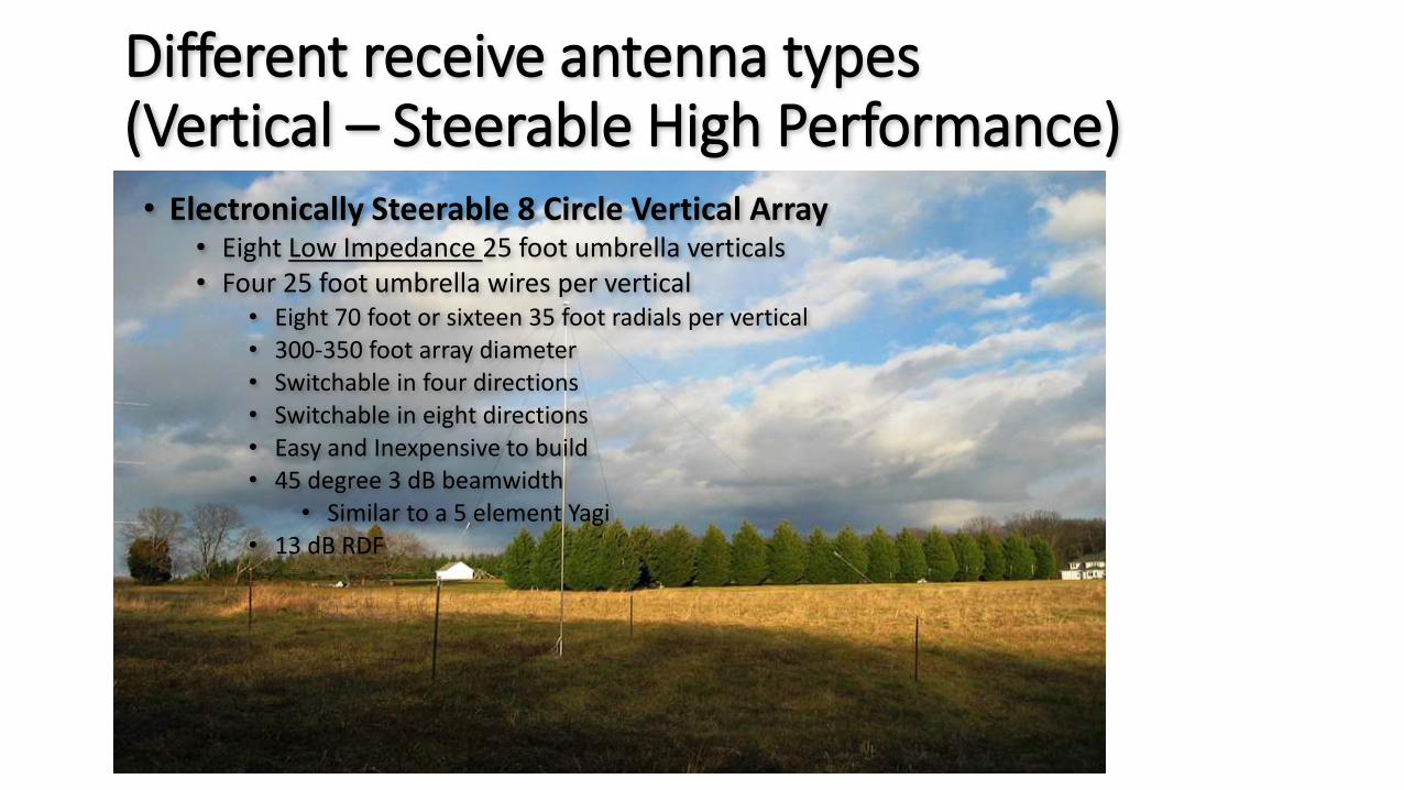
Different receive antenna types(Vertical – Steerable High Performance)• Electronically Steerable 8 Circle Vertical Array
• Eight Low Impedance 25 foot umbrella verticals• Four 25 foot umbrella wires per vertical
• Eight 70 foot or sixteen 35 foot radials per vertical• 300-350 foot array diameter• Switchable in four directions• Switchable in eight directions• Easy and Inexpensive to build• 45 degree 3 dB beamwidth
• Similar to a 5 element Yagi• 13 dB RDF
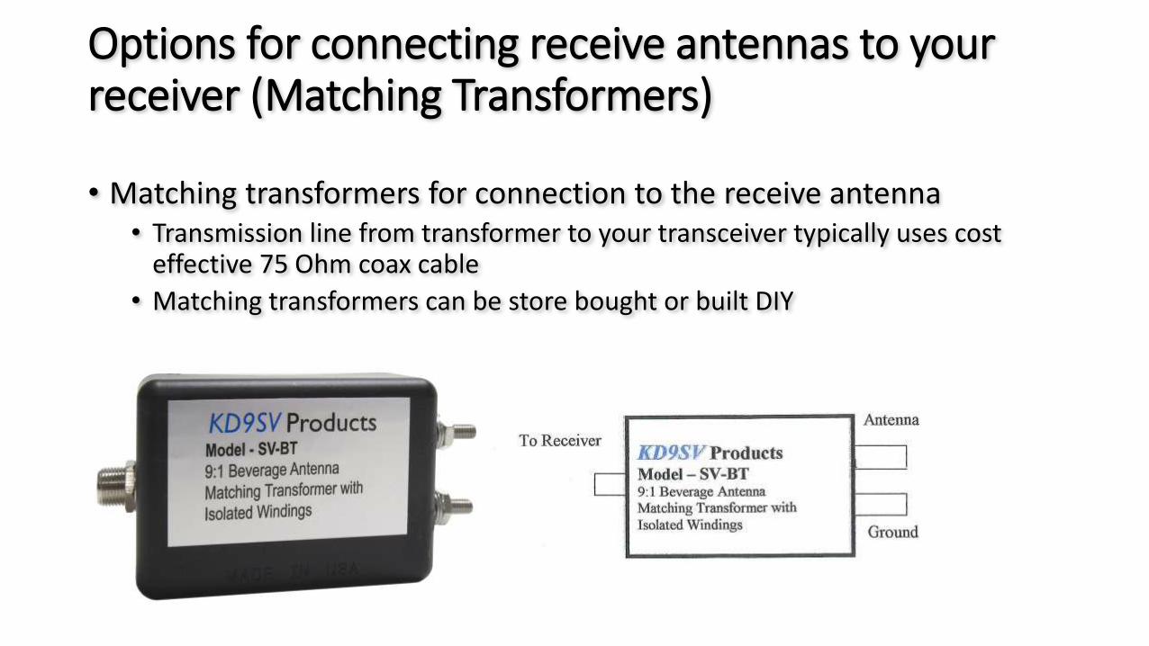
Options for connecting receive antennas to your receiver (Matching Transformers)
• Matching transformers for connection to the receive antenna• Transmission line from transformer to your transceiver typically uses cost
effective 75 Ohm coax cable
• Matching transformers can be store bought or built DIY
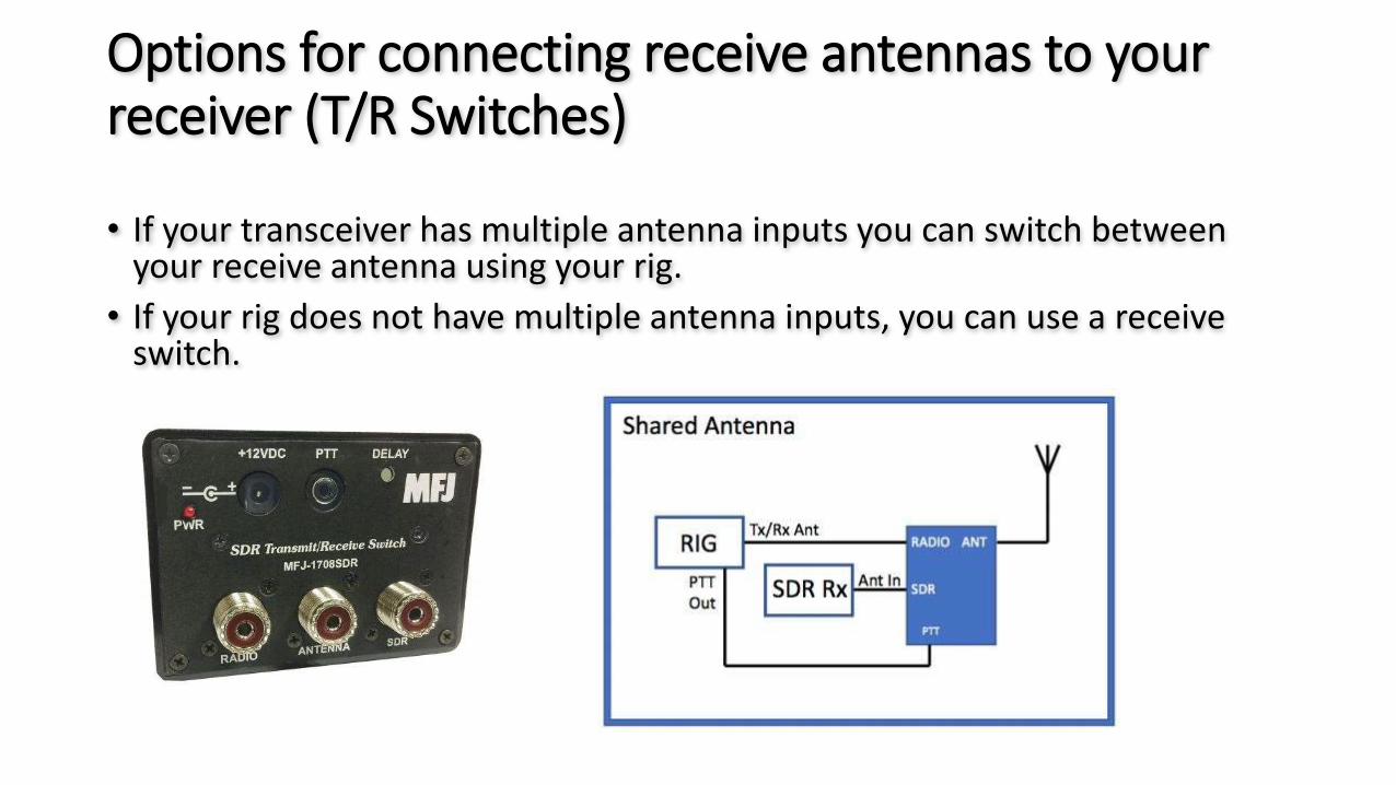
Options for connecting receive antennas to your receiver (T/R Switches)
• If your transceiver has multiple antenna inputs you can switch between your receive antenna using your rig.
• If your rig does not have multiple antenna inputs, you can use a receive switch.

Options for connecting receive antennas to your receiver (T/R Switches – Multiple Input & Preamps)
• For single, or multiple receive antennas, or directions, you can purchase or build switches that have built in preamps.
• Most modern transceivers built in preamps will work just fine. Older rigs and certain receive antenna designs may require outboard preamps.
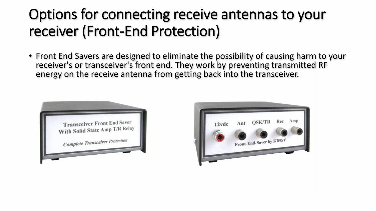
Options for connecting receive antennas to your receiver (Front-End Protection)
• Front End Savers are designed to eliminate the possibility of causing harm to your receiver's or transceiver's front end. They work by preventing transmitted RF energy on the receive antenna from getting back into the transceiver.
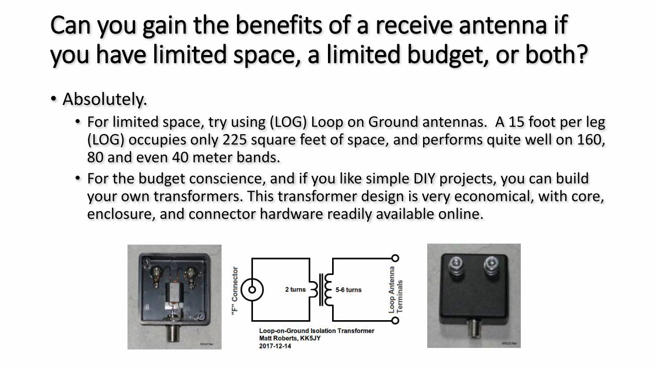
Can you gain the benefits of a receive antenna if you have limited space, a limited budget, or both?
• Absolutely.• For limited space, try using (LOG) Loop on Ground antennas. A 15 foot per leg
(LOG) occupies only 225 square feet of space, and performs quite well on 160, 80 and even 40 meter bands.
• For the budget conscience, and if you like simple DIY projects, you can build your own transformers. This transformer design is very economical, with core, enclosure, and connector hardware readily available online.

Real world examples and A/B comparisonsThis video is comparing an 80m dipole vs 600 foot beverage antenna
Real world examples and A/B comparisonsThis video is comparing a (SAL) Shared Loop Array vs an Inverted L

Thank you!
Silvercreek Amateur Radio AssociationJeff Royer W8TB