recent advances and innovation in steel-concrete composite structures · 2017-08-24 · the 2017...
TRANSCRIPT
The 2017 World Congress on Advances in Structural Engineering and Mechanics (ASEM17) Ilsan(Seoul), Korea, August 28 - September 1, 2017
Recent Advances and Innovation in Steel-Concrete Composite
Structures
*Dennis Lam1) Xianghe Dai2) and Therese Sheehan3)
1), 2), 3) School of Engineering, University of Bradford, Bradford, UK, BD7 1DP 1) [email protected]
ABSTRACT
In modern building constructions, there is an increasing demand on innovative composite flooring systems, which has led to the recent development of various composite floor systems. In this paper, two composite systems are presented which do not required the use of the conventional welded stud shear connectors. The first system made use of the bolted shear connectors while the second system eliminated the use of shear connectors all together. Both composite systems offer vital benefits in terms of reusability as well as long spanning capability without or with fewer secondary beams, shallow floor depth, inherent fire resistance, etc., as well as the advantages offered by the conventional composite beam construction. 1. INTRODUCTION Steel is energy/carbon intensive in production but is a versatile and highly recyclable material. Steel structures are inherently adaptable and demountable with the potential to reuse components. Reuse instead of the common practice of recycling steel by melting, makes good environmental sense, saving both on resources and carbon emissions. Reuse is commercially and technically viable, as demonstrated by isolated projects. In multi-storey building structures, composite construction is one of the most efficient and economic forms of construction. In the UK, for example, composite floors are the most common structural system for multi-storey buildings accounting for around 40% of floor area annually. Composite construction is seen as one of the most important ways of expanding the use of steel buildings in Europe, i.e. increasing market share. However in terms of deconstruction and reuse, current composite construction systems require extensive cutting on-site during the demolition process making reuse not viable. The winners for the future will be those who consider the full life-cycle of their assets, with a strategic plan in place for resilient infrastructure that are designed for the circular economy. We need a new way of thinking and operating if we are to respond to 1) Professor 2) Senior Lecturer 3) Lecturer
Keynote Paper

The 2017 World Congress on Advances in Structural Engineering and Mechanics (ASEM17) Ilsan(Seoul), Korea, August 28 - September 1, 2017
the multiple challenges represented by our changing world. Although it can be hard to think beyond the world we are building and living in now, it is essential that we do so if we are going to create a more sustainable built environment. Embedding circular economy and whole lifecycle thinking is key to creating a more sustainable built environment by improving the design and performance throughout the life cycle of products and services. Milford et al. (2013) analysed the global steel industry and described the mass flows going to various sectors including construction. Steel is easily recycled but this process is energetically costly and the impact of steel use must be reduced further to meet current EU and national emission targets. (Vefago and Avellaneda 2013) A key plank of the strategies proposed by Milford et al. (2013) is increasing reuse. This is particularly relevant for buildings as ‘embodied carbon’ can be a significant proportion of their footprint. In warehouses, which typically have low operational energy, the embodied carbon can be as high as 60% of the cumulative carbon emissions for the building assuming a 15 years lifetime. Even in office buildings, where the use-phase energy is more important, embodied carbon can make up 45% of the total lifecycle carbon although this proportion is highly dependent on the assumed building lifetime. (Webb et al. 2014) This link between construction and embodied emissions has been recognised at the European level, resulting in construction being given specific targets as part of the Circular Economy package pushed by the European Commission (2015). The majority of a building’s embodied carbon and energy is found in the construction materials, and a key energy-intensive material is steel. Indeed, according to Serrenho et al. (2016), the construction industry accounts for one-quarter of all steel consumption in the UK. Reducing demand for new steel in construction is therefore an important strategy for reducing emissions, and the direct reuse of steel sections, in contrast to the carbon intensive process of steel recycling, presents a significant opportunity worth exploring further. Currently, there is a lack of systems approach to maximize the values of building components and materials throughout each stage of the building’s life. There is a failure of integrated thinking of the future value of building components and materials among the stakeholders and a lack of manufacturing innovations to allow reuse and repair of building components that create better value of recycled materials, and an absence of logistics system to enable reuse. Therefore, a system re-design which connects all stages and players in the value chain from feedstock providers, manufacturers, architects and designers, construction teams, demolition and waste management companies and clients, as well as those who finance and regulate the sector by organising the building chain in a circular way while fulfilling the growth ambition is badly needed. To cater for these needs, a four-way strategy that improves the circularity of the construction sector is proposed: (1) Smart design: commit to smart design of buildings in order to make them more suitable for repurposing and for the reuse of materials. (2) Dismantling and separation: efficient dismantling and separation of waste streams enables high value reuse. (3) High-value recycling: high value recovery and reuse of materials and components. (4) Marketplace and resource bank: exchanging commodities between market players. The roadmap and action agenda present a large number of short and long-term actions that can contribute to transforming the

The 2017 World Congress on Advances in Structural Engineering and Mechanics (ASEM17) Ilsan(Seoul), Korea, August 28 - September 1, 2017
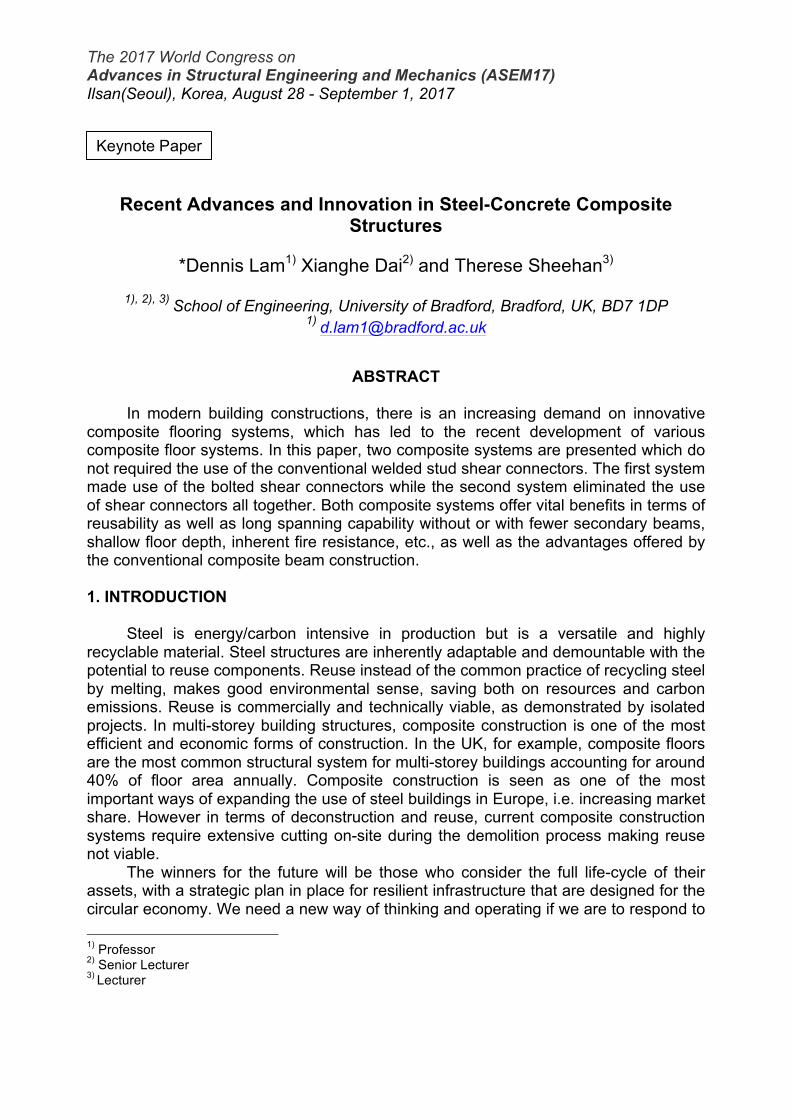
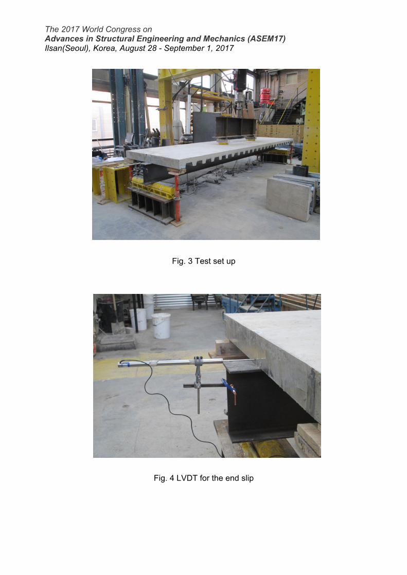
construction chain. For new build, smart designs of buildings is proposed by Lam et al. (2015), Rehman et al. (2016), and Rehman et al. (2017), which are important in the transition of construction circular economy. This has led to research on the reuse of steel beams in composite construction. Steel-concrete composite beams are the most cost effective construction system for multi-storey steel frame buildings owing to the composite action between steel beams and composite slabs. In the current construction practice, composite action is achieved by shear studs welded through the profiled sheeting to the top flange of the steel beam and embedded in the concrete slab which make dismantling, alteration and deconstruction of the composite structures almost impossible. In this paper, two composite systems are presented which do not required the use of the conventional welded stud shear connectors. The first system made use of the bolted shear connectors while the second system eliminated the use of shear connectors all together. Both composite systems offer vital benefits in terms of reusability as well as long spanning capability without or with fewer secondary beams, shallow floor depth, inherent fire resistance, etc., as well as the advantages offered by the conventional composite beam construction. 2. COMPOSITE BEAMS WITH DEMOUNTABLE SHEAR CONNECTORS 2.1 Test Set Up A full-scale composite beam with demountable shear connectors along with an identical composite beam with welded shear connectors were constructed and tested. IPE-300 beam and Arcelor Cofraplus 60 metal profiled decking were used for the test specimens. For the demountable composite beam, holes of 18mm diameter were predrilled at the metal profiled decking and at the top flange of the steel beam. The details of the test specimens are given in Table 6 below. The beam was cast un-propped with profiled decking laid perpendicular to the longitudinal axis of the steel beam. The demountable shear connectors were fastened using traditional construction tools used by steel erectors on site. After the shear connectors were fixed, torque wrench was used to measure the torque achieved by these tools. A torque of 60 Nm (initial pre-tension of 22 kN) was recorded. A single shear connector per trough was used for the composite beam as it is designed for partial shear connection. 19mm diameter × 100mm height demountable shear connectors with 17mm collar diameter were used for the test. The connectors were placed stagger along the steel beam as shown in Figure 1. All test specimens were cast un-propped, after reaching the required concrete strength, a four point loading system was used to apply loads on the simply supported composite beam as shown in Figures 2 and 3. The vertical downward load was applied using the 1000kN hydraulic jack and distributed equally using a spreader beam. Eleven linear variable displacement transducers (LVDTs) were used to measure end slip (Figure 4), vertical deflection and relative slippage between steel beam and the concrete slab at various connector positions (Figure 5).

The 2017 World Congress on Advances in Structural Engineering and Mechanics (ASEM17) Ilsan(Seoul), Korea, August 28 - September 1, 2017
Table 1: Details of the test specimen
Span of steel beam 5600 mm Steel section (S355) IPE 300 Steel strength Concrete compressive strength
420 N/mm2 37 MPa
Length of composite concrete floor 5400 mm Width of composite concrete floor 1340 mm Thickness of composite concrete floor 130 mm Height of metal decking 58 mm
Position of reinforcement mesh Top of steel decking
Number of connectors 26 Connector spacing 227 mm Reinforcement A142 mesh
Fig. 1 Set up before casting of the composite beam
Fig. 2 Loading arrangement
1900 1400 1900
5200
The 2017 World Congress on Advances in Structural Engineering and Mechanics (ASEM17) Ilsan(Seoul), Korea, August 28 - September 1, 2017
Fig. 3 Test set up
Fig. 4 LVDT for the end slip

The 2017 World Congress on Advances in Structural Engineering and Mechanics (ASEM17) Ilsan(Seoul), Korea, August 28 - September 1, 2017
Fig. 5 LVDTs at the 2nd and 4th shear connector’s position
Strain gauges were used to measure the strain in the steel beam and the strain on the top surface of the concrete slab at the mid-span of the beam. The strain measurements are used to determine the position of the neutral axis of composite beam. The specimen was subjected to a sequence of loading cycles, starting with an applied load of 5 kN/m2 (excluding the weight of the specimen and spreader beams) and subsequent cycles of 7.5 kN/m2, 15 kN/m2 and finally loaded to failure. 2.2 Test Results Table 2 presents the test results of composite beam with demountable shear connectors (CB-DSC) and composite beam with the traditional welded shear connectors (CB-WSC). Figure 6 shows that load deflection curves of composite beam with demountable shear connectors and the equivalent composite beam with the traditional through deck welded shear connectors respectively. Initially, the beam was loaded up to 5 kN/m2 (working load) and this was cycled for three times to observe any initial slip and deflection. Then the load was increased to 7.0 kN/m2 and 15 kN/m2 respectively. Then, the load was increased by an increment of 1kN/m2 until 70% of the predicted failure load was reached. After that, the load was increased by displacement until failure was reached. From Figure 6, it can be seen that at ultimate load, the mid-span deflection for the composite beam with demountable shear connectors reached 80 mm (more than span / 70), this showed that the beam exhibited excellent ductility. The test was terminated at this point as steel was fully yielded while the load deflection behaviour remains stable. There were some concrete cracks on the top surface in the longitudinal direction along the steel beam. No major cracking was observed on the side of the concrete slab. No

The 2017 World Congress on Advances in Structural Engineering and Mechanics (ASEM17) Ilsan(Seoul), Korea, August 28 - September 1, 2017
deck separation, shear connector failure or concrete pull out were observed during the test. In addition to this, there was little evidence that uplift of composite slab occurred throughout the test.
Table 2. Test results of composite beams Figure 6 shows the comparison of welded and demountable specimen. The demountable composite floor system showed almost similar resistance but slightly lower initial stiffness. However, the overall stiffness was higher than the beam with welded connectors. The composite beam with demountable shear connectors has demonstrated significantly higher ductility. There was an initial deflection due to the clearance holes in demountable specimen, which was not observed in the welded specimen.
Fig. 6 Moment vs. mid-span deflection
The maximum mid-span deflection and residual defection against applied floor load obtained from the test is presented in the Table 3. The residual deflection of 0.6mm was observed at the first cycle of loading. This was due to the hole clearance in
Test specimen
ID
Concrete strength (MPa)
Max. load at failure
(kN)
Max. moment
resistance (kNm)
Deflection at max.
load (mm)
CB-DSC 37 340.6 323.6 79.9 CB-WSC 36 333.1 316.5 59.1
0
50
100
150
200
250
300
350
0 10 20 30 40 50 60 70 80 90
Mom
ent (
kNm
)
Mid-span Deflection (mm)
CB-WSC
CB-DSC

The 2017 World Congress on Advances in Structural Engineering and Mechanics (ASEM17) Ilsan(Seoul), Korea, August 28 - September 1, 2017
steel flange. But no further residual deflection was seen as this loading cycle was repeated for three more time. The moment vs. deflection curve (Figure 6) is linear up to the 70% of ultimate loading. This shows a stable linear behaviour in the elastic region. The load vs. end slips is presented in Figure 7. The end slips at both ends show that there is a modest asymmetry in the behaviour of shear connectors, more than 6 mm of slip were recorded at both ends. This fulfils the EC4 requirement for ductility. At the first loading, an initial average slip of 0.09mm was observed due the clearance between the connector and predrilled holes in the steel flange. But this initial slip did not increase after repeating the same loading cycle for three times.
Table 3. Deflection at mid-span
Load cycles 1.0 x working load
1.5 x working load
3.0 x working load
Maximum load at failure
5.0 kN/m2 7.5 kN/m2 15.0 kN/m2 47.0 kN/m2 Deflection at each loading cycle (mm) 2.8 1.9 4.1 71.1
Residual deflection (mm) 0.6 0.7 1.0 43.3
Cumulative residual deflection (mm) 0 0.6 1.3 2.3
Cumulative deflection (mm) 2.8 5.3 10.1 82.2
Fig. 7 Load-slip curves of the composite beam with demountable shear connectors
0
50
100
150
200
250
300
350
400
0 1 2 3 4 5 6 7 8 9 10
Load
(kN
)
End-slip (mm)
End Slip_L
End Slip_R

The 2017 World Congress on Advances in Structural Engineering and Mechanics (ASEM17) Ilsan(Seoul), Korea, August 28 - September 1, 2017
After the test, the demountable composite floor system was evaluated for the purpose of demountability and to determine whether the structural parts of the demountable composite floor system can be reused at the end of the design life. All the demountable shear connectors were undone after the test was terminated, even those some permanent deformation was observed in the beam, the composite concrete slab could still be easily lifted off from the steel beam without any problem at the end of the test. This will allow the steel beam to be reused after the structural design life without going into recycling process. Figure 8 shows the demountability of this form of composite beam.
Fig. 8 Demountability of the composite beam
3. SLIM FLOOR COMPOSITE BEAMS 3.1 Test Set Up The tested specimens comprised a HEB200 steel section on top of a steel plate (400 mm wide × 15 mm thick), with the HEB section embedded in a concrete slab shown in Figure 9. The concrete slab was 120 mm thick, except for the region immediately adjacent to the steel section, with 40 mm cover on top of the steel top flange, giving a total specimen depth of 240 mm. The slab was 2 m wide and the shear beam was simply supported with a span of 4 m between supports. 40 mm diameters holes were cut from the web of the HEB section at 400 mm spacing, and a T16 reinforcing bar was passed through each hole, transverse to the beam length, to provide shear connection. The specimens were designed to have a degree of shear connection equal to 40% between the steel and concrete. A252 mesh reinforcement was used in the top of the concrete slab, positioned directly above the top of the steel beam.

The 2017 World Congress on Advances in Structural Engineering and Mechanics (ASEM17) Ilsan(Seoul), Korea, August 28 - September 1, 2017
Fig. 9 Cross-sectional view of test specimens
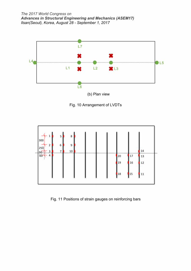
The loading was to be applied at a 300 mm eccentricity on each side of the cross-section, as shown in Figure 9, and at two locations along the specimen length, at a distance of 1.5 m from the supports, giving a total of four load application points. Grade S355 steel was used for the HEB section and bottom plate. The yield strength and ultimate strength of the HEB-200 section were 428 MPa and 519 MPa respectively, whereas the values for the bottom plate were 455 MPa and 525 MPa respectively. The concrete compressive strength on the test date was 41.3 MPa and the tensile splitting strength was 2.1 MPa. Six LVDTs were employed to measure deformations during the test. The positions of these for specimen are shown with respect to the loading positions in Figure 10. LVDTs L1, L2 and L3 measured the vertical deflection along the mid-length, L4 and L5 measured the end-slip and L6 and L7 measured the vertical deflections at the edge of the concrete slab. 20 strain gauges were placed on the reinforcement bars for slim floor beam, the arrangement of which is shown in Figure 11, to ascertain which of these connectors is activated during the test. Strain gauges were also placed on the top steel flange and the bottom steel plate, to measure strain in the longitudinal direction. 5 strain gauges were also placed on the top of the concrete slab. The entire specimen and test set-up is depicted in Figure 12. A 250 tonne hydraulic actuator was chosen to apply the loading and a system of spreader beams was placed upon the concrete slab in order to distribute the load between the four loading points.
(a) Elevation
L4 L5
L3 L2 L1, L6, L7
The 2017 World Congress on Advances in Structural Engineering and Mechanics (ASEM17) Ilsan(Seoul), Korea, August 28 - September 1, 2017
(b) Plan view
Fig. 10 Arrangement of LVDTs
Fig. 11 Positions of strain gauges on reinforcing bars
L1 L2 L3
L4 L5
L7
L6
1
2
3 4
5
6
7
8
9
10
11
12
13 14
15
16
17
18
19
20
300
250 50 50

The 2017 World Congress on Advances in Structural Engineering and Mechanics (ASEM17) Ilsan(Seoul), Korea, August 28 - September 1, 2017
Fig. 12 Specimen in test-rig
2.2 Test Results Loading was applied in small increments to the specimen, until failure eventually occurred, i.e. strains in the steel bottom plate had exceeded the yield stress. The relationship between load and mid-span deflection for the slim floor specimen is shown in Figure 13. The maximum loads recorded was 732 kN. The load was applied by the hydraulic actuator using displacement control. As each increment, a static load was

The 2017 World Congress on Advances in Structural Engineering and Mechanics (ASEM17) Ilsan(Seoul), Korea, August 28 - September 1, 2017
recorded before the next load increment was applied, this are evident from Figure 13. The lower bound for slim floor beam is shown by the continuous line in the figure. If the static loads are used for the specimen, the maximum load decrease to 700 kN for the slim floor beam. The degree of shear connection is calculated to be equal to 40%, the predicted moment capacity of the beam would be 492 kNm, using the measured material properties, which equates to an applied load of 656 kN. Hence, the actual failure load for the specimen was slightly higher than the predicted load with 40% shear connection. The slim floor beam specimen exhibited a three phases behaviour during the tests: an uncrack phase, up to a load of approximately 300 kN; a cracked phase, in the stiffness decreased to approximately half of the initial value, and the response became increasingly nonlinear; and finally, a plastic phase during which the load-displacement relationship displayed a plateau. The specimen had a large residual mid-span deflection after unloading.
Fig. 13 Relationship between load and mid-span vertical deflection Figure 14 presents the relationship between load and end-slip at each end, very little slip occurred up to load of 300 kN, after which the load-slip relationship became increasingly nonlinear until reaching a maximum value at specimen failure. Strains in the transverse steel bars were very low (less than 150 µε) up to a load of 300 kN, but as the applied load and slippage increased, the strains in the bars also increased considerably, showing the activation of these in resisting slippage. After the test, the slip could be clearly seen at the end of the specimen, as shown in Figure 15.
0
100
200
300
400
500
600
700
800
0 10 20 30 40 50 60 70 80 90 100
Load
(kN
)
Mid-span deflection (mm)

The 2017 World Congress on Advances in Structural Engineering and Mechanics (ASEM17) Ilsan(Seoul), Korea, August 28 - September 1, 2017
Fig. 14 Relationship between load and end-slip
Fig. 15 Visible slip between steel beam and concrete slab of the slim floor beam
0
100
200
300
400
500
600
700
800
0 2 4 6 8 10 12 14 16
Load
(kN
)
End-slip (mm)
L4
L5

The 2017 World Congress on Advances in Structural Engineering and Mechanics (ASEM17) Ilsan(Seoul), Korea, August 28 - September 1, 2017
After the test, the slim floor beam was evaluated for the purpose of reusability and to determine whether the steel section of the slim floor system can be reused at the end of the design life. The slab of the slim floor beam was first saw cut to separate the steel section from the slab as shown in Figure 16, after that, the concrete around the steel section was removed to allow the steel beam to be reused after the structural design life without going into recycling process. Figure 17 shows the steel section can be reclaimed from the slim floor beam even with excessive deformation after the ultimate load test.
Fig. 16 Slim floor beam after saw cut

The 2017 World Congress on Advances in Structural Engineering and Mechanics (ASEM17) Ilsan(Seoul), Korea, August 28 - September 1, 2017
Fig. 17 Steel section extracted from the slim floor beam 4. CONCLUSIONS In this paper, two composite systems are presented which do not required the use of the conventional welded stud shear connectors. The first system made use of the bolted shear connectors while the second system eliminated the use of shear connectors all together. Both composite systems offer vital benefits in terms of reusability as well as long spanning capability without or with fewer secondary beams, shallow floor depth, inherent fire resistance, etc., as well as the advantages offered by the conventional composite beam construction. REFERENCES European Commission (2015), Communication from the Commission to the European
Parliament, the Council, the European Economic and Social Committee and the Committee of the Regions. On resource efficiency opportunities in the building sector.
Lam, D., Dai, X.H., Kuhlmann, U., Raichle, J. and Braun, M. (2015), 'Slim-floor construction - design for ultimate limit state', Steel Construction – Design and Research, Vol. 8(2), pp. 79 – 84.
Milford, R.L., Pauliuk, S., Allwood, J.M. and Müller, D.B. (2013), The roles of energy and material efficiency in meeting steel industry CO2 targets, Environ. Sci. Technol. 47, 3455–3462.
The 2017 World Congress on Advances in Structural Engineering and Mechanics (ASEM17) Ilsan(Seoul), Korea, August 28 - September 1, 2017
Rehman, N., Lam D., Dai X., Ashour, A.F. (2016), ‘Experimental study on demountable shear connectors in composite slabs with profiled decking’, Journal of Constructional Steel Research, Vol. 122, pp. 178 – 89.
Rehman, N., Lam D., Dai X., Ashour, A.F. (2017), ‘Testing of composite beam with demountable shear connectors’, Proceedings of the Institution of Civil Engineers: Structures and Buildings, Vol. 170, pp. 1 – 14.
Serrenho, A.C., Mourão, Z.S., Norman, J., Cullen, J.M. and Allwood, J.M. (2016), The influence of UK emissions reduction targets on the emissions of the global steel industry, Resour. Conserv. Recycl., 107, 174–184.
Vefago, L.H.M. and Avellaneda, J., (2013), Recycling concepts and the index of recyclability for building materials, Resour. Conserv. Recycl., 72, 127–135.
Webb, N., Broomfield, M., Brown, G., Buys, G., Cardenas, L., Murrels, T., Pang, Y., Thistlethwaite, G. and Watterson, J. (2014), UK greenhouse gas inventory 1990 to 2012: Annual report for submission under the framework convention on climate change, Department of Energy and Climate Change.