recent advances in modeling fatigue in metals
DESCRIPTION
Recent Advances in Modeling Fatigue in Metals. Symposium in honor of C. Tome TMS, San Diego, February 28, 2011. H. Sehitoglu, M. Sangid,T. Ezaz, H.J.Maier University of Illinois, USA, University of Paderborn, Germany. Work Supported by Rolls Royce, National Science Foundation, DMR, Metals. - PowerPoint PPT PresentationTRANSCRIPT

Department of Mechanical Science and Engineering
University of Illinois at Urbana-Champaign
www.mechse.uiuc.edu1
Recent Advances in Modeling Fatigue in Metals
Symposium in honor of C. TomeTMS, San Diego, February 28, 2011
Work Supported by Rolls Royce, National Science Foundation, DMR, Metals
H. Sehitoglu, M. Sangid,T. Ezaz, H.J.MaierUniversity of Illinois, USA, University of Paderborn, Germany

OutlineModeling of Fatigue• Analysis of Grain Boundaries- Energy Barriers
for G.B. Slip Transmission And G.B. Slip Nucleation
• Energy Formulation for Crack Initiation via Persistent Slip Bands, Life results
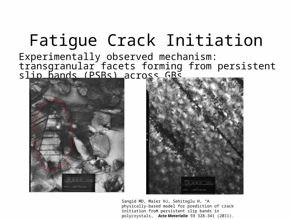
Fatigue Crack InitiationExperimentally observed mechanism: transgranular facets forming from persistent slip bands (PSBs) across GBs
Sangid MD, Maier HJ, Sehitoglu H, “A physically-based model for prediction of crack initiation from persistent slip bands in polycrystals,” Acta Materialia 59 328-341 (2011).

Atomic SimulationsUse Molecular Dynamics Code, LAMMPs • Construct GBs from crystal lattices (axis/angle pairs)• Ni with Foiles-Hoyt EAM Potential: FCC Structure• 3D Periodic Boundary Conditions• Atoms ‘relax’ to determine grain boundary energy
GB ECSL
GB N
MEPerfect
FCC
Area
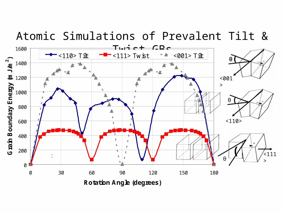
Atomic Simulations of Prevalent Tilt & Twist GBs
<001>
( <111>θ
<110>
θ (
0
200
400
600
800
1000
1200
1400
1600
0 30 60 90 120 150 180
Rotation Angle (degrees)
Gra
in B
ou
nd
ary
En
erg
y (m
J/m
2 ) <110> Tilt <111> Twist <001> Tilt
Perfect FCC
Perfect FCCΣ3
Σ9
Σ11
Σ17
Σ19Σ5 Σ5
Σ3 Σ3
Σ7Σ13
Σ21
Σ7Σ13
Σ21
Σ7Σ13
Σ21
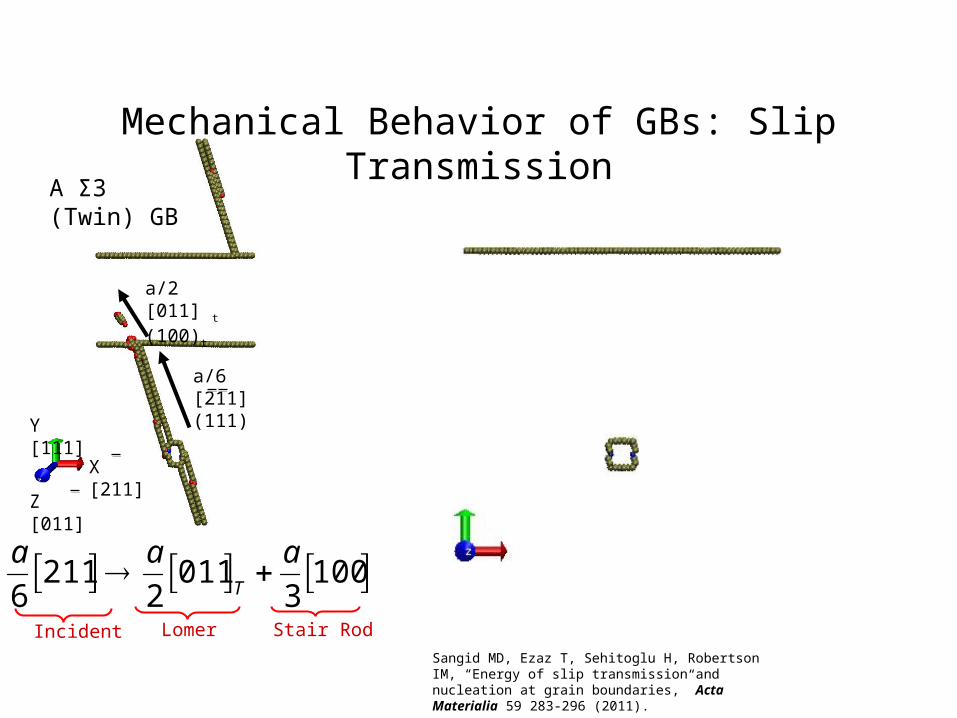
Mechanical Behavior of GBs: Slip Transmission
A Σ3 (Twin) GB
Y [111]
Z [011]
X [211]
a/2 [011] t (100)t
a/6 [211](111)
Stair RodLomerIncident
a
6211 a
2011 T
a
3100
Sangid MD, Ezaz T, Sehitoglu H, Robertson IM, “Energy of slip transmission and nucleation at grain boundaries,” Acta Materialia 59 283-296 (2011).
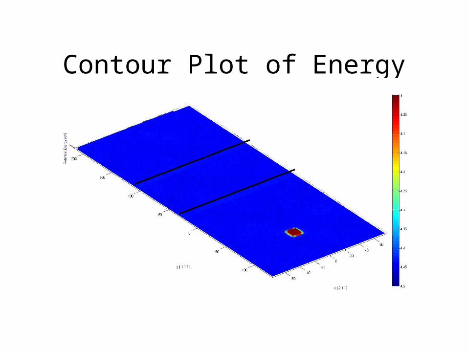
Contour Plot of Energy Barriers
0
50
100
150
200
250
300
350
400
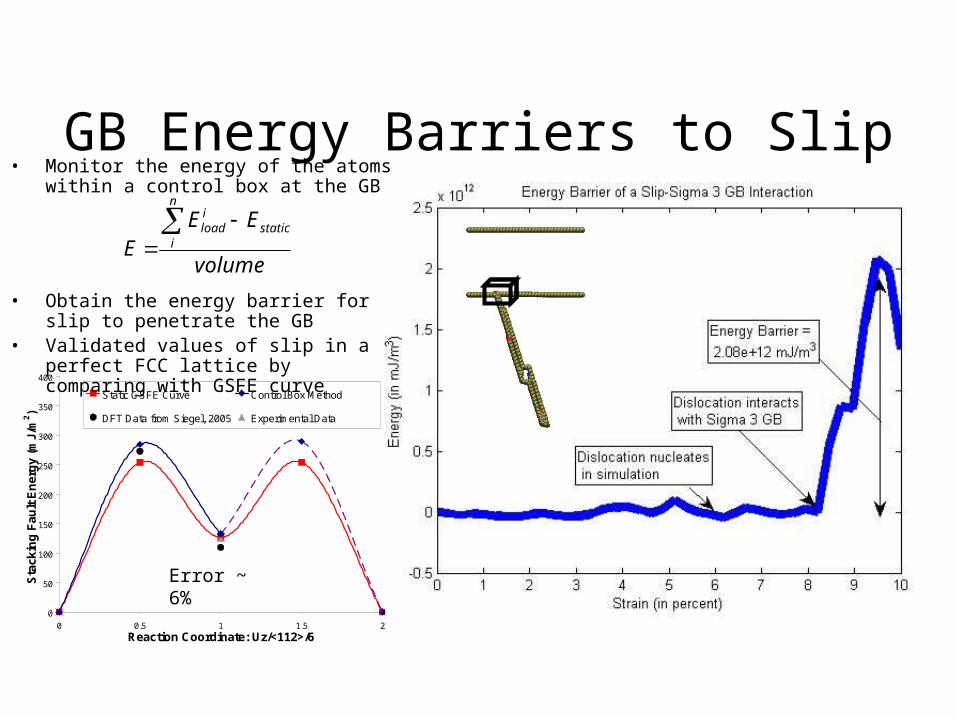
0 0.5 1 1.5 2Reaction Coordinate: Uz/<112>/6
Sta
ck
ing
Fa
ult
En
erg
y (m
J/m
2)
Static GSFE Curve Control Box Method
DFT Data from Siegel, 2005 Experimental Data
GB Energy Barriers to Slip• Monitor the energy of the atoms within a
control box at the GB
• Obtain the energy barrier for slip to penetrate the GB
• Validated values of slip in a perfect FCC lattice by comparing with GSFE curve
volume
EEE
n
istatic
iload
Error ~ 6%

Measured Energy Barrier for Slip Transmission for various GBs

Validation of MD Results of Slip Transmission

Criterion for Slip Transmission• Geometrical condition
– Minimizes angle between lines of intersection of slip planes with GB, maximize M:
• Resolved shear stress condition– After predicting active slip
plane from GC, choose direction based on max resolved shear stress
• Residual grain boundary dislocation condition
– Minimize Burgers vector of residual dislocation (difference in b of incoming and outgoing ):┴
Lee, Robertson, and Birnbaum, 1989

0.0E+00
5.0E+11
1.0E+12
1.5E+12
2.0E+12
2.5E+12
0 200 400 600 800 1000 1200 1400
Static GB Energy (mJ/m2)
En
erg
y B
arri
er f
or
Dis
loca
tio
n -
GB
Inte
ract
ion
(m
J/m
3 )
Σ7
Σ21
Σ17
Σ9Σ19
Σ5
Σ3
Σ11
Σ13
Perfect FCC
Energy Barriers for Slip Transmission through GB
6.013108.2
GBStatic
onTransmissiBarrier EE
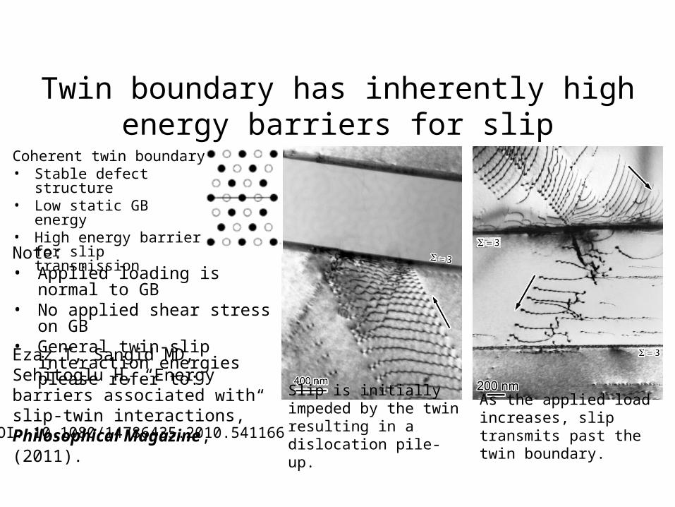
Twin boundary has inherently high energy barriers for slip transmission
As the applied load increases, slip transmits past the twin boundary.
Slip is initially impeded by the twin resulting in a dislocation pile-up.
Ezaz T, Sangid MD, Sehitoglu H, “Energy barriers associated with slip-twin interactions,” Philosophical Magazine, (2011).
Coherent twin boundary• Stable defect structure• Low static GB energy• High energy barrier for
slip transmissionNote:• Applied loading is normal to GB• No applied shear stress on GB• General twin-slip interaction
energies please refer to:
DOI: 10.1080/14786435.2010.541166

Measured Energy Barrier for Slip Nucleation from various GBs

0.0E+00
2.0E+11
4.0E+11
6.0E+11
8.0E+11
1.0E+12
1.2E+12
1.4E+12
1.6E+12
1.8E+12
2.0E+12
0 200 400 600 800 1000 1200 1400
Static GB Energy (mJ/m2)
En
erg
y to
Nu
clea
te a
Dis
loca
tio
n (
mJ/
m3) Σ7
Σ21Σ13
Σ17
Σ9
Σ19
Σ5
Energy Barriers for Slip Nucleation from GBPlease note: the Σ1,3,&11 GBs have a simple dislocation structure and stable configurations. Hence dislocations were nucleated in the matrix material during the simulation, preventing the energy barrier to be measured

Fatigue Crack InitiationExperimentally observed mechanism: transgranular facets forming from persistent slip bands (PSBs) across GBs
Sangid MD, Maier HJ, Sehitoglu H, “A physically-based model for prediction of crack initiation from persistent slip bands in polycrystals,” Acta Materialia 59 328-341 (2011).
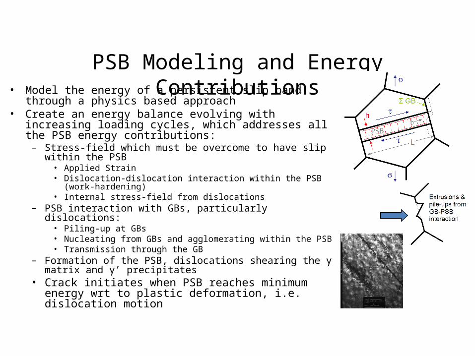
PSB Modeling and Energy Contributions• Model the energy of a persistent slip band through a physics
based approach• Create an energy balance evolving with increasing loading
cycles, which addresses all the PSB energy contributions:– Stress-field which must be overcome to have slip within the PSB
• Applied Strain• Dislocation-dislocation interaction within the PSB (work-hardening)• Internal stress-field from dislocations
– PSB interaction with GBs, particularly dislocations:• Piling-up at GBs• Nucleating from GBs and agglomerating within the PSB• Transmission through the GB
– Formation of the PSB, dislocations shearing the γ matrix and γ’ precipitates
• Crack initiates when PSB reaches minimum energy wrt to plastic deformation, i.e. dislocation motion

Energy Formulation for a PSB
Extrusion Formation at GBs
Applied Work
Conti
nuum
MD
Dislocation Pile-ups
Shearing of γ’ PrecipitatesDislocation Nucleation at GBs
where:
σ ≡ Applied stress
h ≡ Width of PSB
d ≡ Dislocation spacing
ρ ≡ PSB dislocation density
N ≡ Number of cycles
Monitor a PSB and when it reaches a stable point, the material fails!
Work Hardening in Bands
Shearing of γ Matrix
Energy Eapp (,m,L,N) Ehard (,L,N) E pile up
disl (h,d,L,N)
Enucdisl (m,,h,L,L',N) E extrusion
slip GB (m,,h,L,L',N) EAPB (L, dist ,N) E SF (L, dist ,N)
Each term is expressed in terms of a slip increment, ∂X
m ≡ Schmid factor
L ≡ Grain size
Σ ≡ Characteristic of GB
γ’ ≡ Distribution of precipitate
L’ ≡ Grain size of neighboring grain
Exp
func
tions
Mic
rost
ruct
ure
Inpu
ts
Output
Sangid MD, Maier HJ, Sehitoglu H, “A physically-based model for prediction of crack initiation from persistent slip bands in polycrystals,” Acta Materialia 59 328-341 (2011).
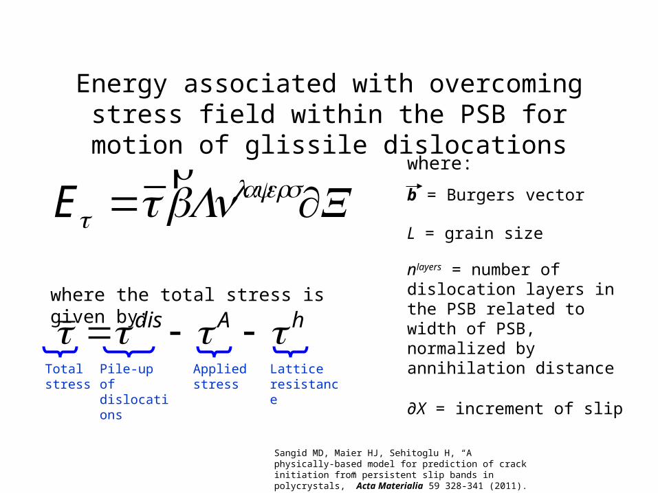
nlayers = number of dislocation layers in the PSB related to width of PSB, normalized by annihilation distance
Energy associated with overcoming stress field within the PSB for motion of glissile dislocations
dis A hwhere the total stress is given by:
Total stress
Pile-up of dislocations
Applied stress
Lattice resistance
E =rbLnlayers∂X
L = grain size
∂X = increment of slip
b = Burgers vector
where:
Sangid MD, Maier HJ, Sehitoglu H, “A physically-based model for prediction of crack initiation from persistent slip bands in polycrystals,” Acta Materialia 59 328-341 (2011).

PSB-GB Interaction EnergyAtomistic Based Formulation:• Dislocations nucleate from the GB and localize
in slip bands
– The number of dislocations that are emitted from the GB and aggregate within the PSB is given by:
• PSBs form extrusions at grain boundaries in polycrystalline material
• Leverage energy barriers for slip transmission and nucleation at a GB from atomic simulations (previously shown)
Eextrusion
slip−GB = ∂Xi ⋅EMD−slip−GBndis
penrb
i∑ h
Enuc
disl = ∂Xi ⋅EMD−nuc−GB −o( )
rbhL2
i∑
o hL
Sangid MD, Maier HJ, Sehitoglu H, “The role of grain boundaries in fatigue crack initiation – an energy approach,” Accepted to International Journal of Plasticity (In Press - 2011).

Energy due to shearing γ matrix and γ’ precipitates
Shearing of γ’ precipitates O O’M M’R
Atomistic Based Formulation:
Stacking Fault Energy + Anti-Phase Boundary Energy
where f is the area fraction of γ’, fU720 ~ 0.20
EAPB + E−SF = f APB dLo
d
∫ + 1− f( ) SF dLo
d
∫( )nefflayers∂X
Sangid MD, Maier HJ, Sehitoglu H, “A physically-based model for prediction of crack initiation from persistent slip bands in polycrystals,” Acta Materialia 59 328-341 (2011).

PSB Energy Balance
Sangid MD, Maier HJ, Sehitoglu H, “A physically-based model for prediction of crack initiation from persistent slip bands in polycrystals,” Acta Materialia 59 328-341 (2011).
Sangid MD, Ezaz T, Sehitoglu H, Robertson IM, “Energy of slip transmission and nucleation at grain boundaries,” Acta Materialia 59 283-296 (2011).

Criterion for Crack Initiation• Create an expression for energy (as energy components were
previously shown) • Increment the number of loading cycles and update the energy
expression as variables evolve:
• Criterion for crack initiation– Energy of PSB reaches a stable value– Minimize energy to check for stability of PSB:
where Xi represents the position of the glissile (mobile) dislocations in our energy expression
0
iX
E
layerseff
layerspendis
A nnndh ,,,,,,
Sangid MD, Maier HJ, Sehitoglu H, “A physically-based model for prediction of crack initiation from persistent slip bands in polycrystals,” Acta Materialia 59 328-341 (2011).
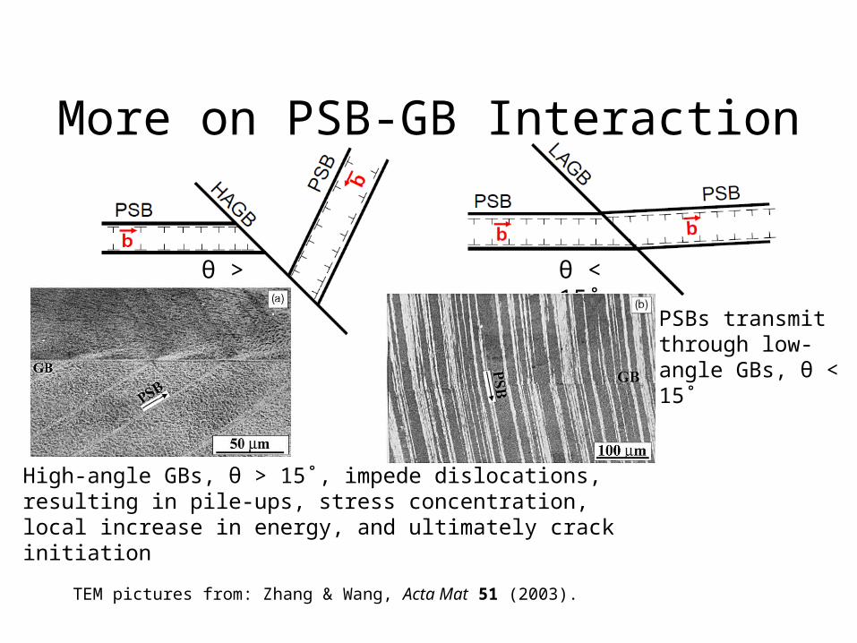
More on PSB-GB Interaction
TEM pictures from: Zhang & Wang, Acta Mat 51 (2003).
θ < 15˚
θ > 15˚
PSBs transmit through low-angle GBs, θ < 15˚
High-angle GBs, θ > 15˚, impede dislocations, resulting in pile-ups, stress concentration, local increase in energy, and ultimately crack initiation

Clustering of grains
Grain cluster (multiple grains connected by LAGBs)
Failure occurs due to PSB-GB interaction
Single large grain
or

Fatigue Scatter Results
0.6
0.7
0.8
0.9
1
1.1
1.2
100 1000 10000 100000 1000000Cycles to Initiation
No
rmal
ized
Ap
plie
d S
trai
n R
ang
e, %
Model - Simulated SpecimensModel - AverageU720 Experimental DataU720 Data - Average
1000 simulated specimens vs. 84 experimental results
Each simulated specimen takes <30 seconds to construct its microstructure and predict fatigue life for a series of strain ranges
Sangid MD, Maier HJ, Sehitoglu H, “An energy-based microstructure model to account for fatigue scatter in polycrystals,” Journal of the Mechanics and Physics of Solids (In Press - 2011).

Conclusions• Atomistic Simulations
– Quantified the strengthening mechanisms of slip transmission and nucleation from GBs
– Inverse correlation between energy barrier and static interfacial energy
• Lower GB energy results in a stronger barrier.
• Fatigue modeling– Introduced methodology to model persistent slip bands energetics, in
order to predict fatigue life.
• Prediction of fatigue life– Accurately predict scatter in a deterministic framework