recent advances in pulsed-laser deposition of complex …addis.caltech.edu/research/rec adv in pld...
TRANSCRIPT

IOP PUBLISHING JOURNAL OF PHYSICS: CONDENSED MATTER
J. Phys.: Condens. Matter 20 (2008) 264005 (16pp) doi:10.1088/0953-8984/20/26/264005
Recent advances in pulsed-laser depositionof complex oxidesH M Christen and G Eres
Materials Science and Technology Division, Oak Ridge National Laboratory, Oak Ridge,TN 37831, USA
Received 14 January 2008Published 9 June 2008Online at stacks.iop.org/JPhysCM/20/264005
AbstractPulsed-laser deposition (PLD) is one of the most promising techniques for the formation ofcomplex-oxide heterostructures, superlattices, and well controlled interfaces. The first part ofthis paper presents a review of several useful modifications of the process, including methodsinspired by combinatorial approaches. We then discuss detailed growth kinetics results, whichillustrate that ‘true’ layer-by-layer (LBL) growth can only be approached, not fully met, eventhough many characterization techniques reveal interfaces with unexpected sharpness.Time-resolved surface x-ray diffraction measurements show that crystallization and themajority of interlayer mass transport occur on timescales that are comparable to those of theplume/substrate interaction, providing direct experimental evidence that a growth regime existsin which non-thermal processes dominate PLD. This understanding shows how kinetic growthmanipulation can bring PLD closer to ideal LBL than any other growth method available today.
(Some figures in this article are in colour only in the electronic version)
1. Introduction
Interfaces and crystalline superlattice materials are ofincreasing interest to a large and growing fraction of thecondensed matter physics community. In fact, the deterministicsynthesis of such completely artificial crystalline structuresallows us to go beyond equilibrium materials in exploringnew properties, developing new functionalities, and analyzingfundamental physical processes.
Transition-metal oxides are particularly interesting build-ing blocks for such structures, as they possess a great num-ber of interesting intrinsic properties [1]. However, the pre-cise assembly of such layers into artificial superlattices re-quires atomic-scale control. Pulsed-laser deposition [2–5],long known as the tool of choice for the growth of complex-oxide materials, has recently been applied to the growth of in-terfaces [6, 7] with a sharpness that was previously thought tobe obtainable in molecular-beam epitaxy methods [8, 9] butnot PLD. With the prospect of forming such artificial materi-als, it has become critically important to understand the fun-damental limits in obtaining atomically flat growth surfaces.This is complicated by the scarcity of tools to investigate—at an atomic scale—the quality of an interface: final surfacescan be characterized, for example, by atomic-force microscopy(AFM) (with a lateral spatial resolution of many unit cells), but
embedded interfaces can potentially be very different. Scan-ning transmission electron microscopy (STEM) gives accessto a projection of a specimen with thickness of a few tens ofnanometers. Broadening of the observed interfaces is often at-tributed to various types of defects and surface steps as well asto an intrinsic dechanneling of the electron beam as it traversesthe sample. Thus, it is rarely possible to distinguish betweena true atomically flat interface and one with a non-vanishingroughness of—for example—a single unit cell.
Surface x-ray diffraction (SXRD) provides an alternativemeans to explore the question of how smooth a layer canbe ultimately for a given growth environment, and theresults illustrate the importance of considering the fundamentallimits beyond the current microscopic techniques’ capabilities.True layer-by-layer growth is known to be fundamentallyimpossible by any currently available growth technique [10],and our time-resolved SXRD observations clearly confirm thisobservation for homoepitaxial PLD of SrTiO3. In addition,however, our results provide an explanation for the surprisingsuccess of PLD and provide guidance for further improvementsof the method.
The purpose of this paper is to discuss the fundamentalsof growth in the context of SXRD observations of the PLDprocess. Before this, however, we give a brief overviewof the pulsed-laser deposition method as applied to metal
0953-8984/08/264005+16$30.00 © 2008 IOP Publishing Ltd Printed in the UK1
J. Phys.: Condens. Matter 20 (2008) 264005 H M Christen and G Eres
oxides, without pretending to provide a comprehensive review.Such reviews can be found in the literature, where thegrowth of complex metal-oxide films by PLD is compared toresults obtained by other techniques [5, 11]. In this paper,however, we aim to provide a tutorial-style introduction toPLD, focus on specific issues that need to be addressed, anddescribe modifications of the process that have allowed us toapply the method to a number of systematic investigations.This paper first describes efficient techniques (compositionalspread, temperature gradient, etc), and then focuses on thedetails of nucleation and growth, with a strong emphasis onresults from time-resolved SXRD.
2. Basic concepts
2.1. Development of PLD
The use of a pulsed laser to induce the stoichiometrictransfer of a material from a solid source to a substrate,simulating earlier flash evaporation methods, is reported in theliterature as early as 1965 [12], where films of semiconductorsand dielectrics were grown using a ruby laser. Pulsed-laser evaporation for film growth from powders of SrTiO3
and BaTiO3 was achieved in 1969 [13]. Six years later,stoichiometric intermetallic materials (including Ni3Mn andlow-Tc superconducting films of ReBe22) were producedusing a pulsed-laser beam [14]. In 1983, Zaitsev-Zotovand co-workers reported for the first time superconductivityin pulsed-laser evaporated BaPb1−xBix O3 films after heat-treatment [15]. The real breakthrough for PLD, however,was its successful application to the in situ growth ofepitaxial high-temperature superconductor films in 1987 atBell Communications Research [16].
Since then, PLD has been used extensively in thegrowth of these high-temperature cuprates and numerousother complex oxides, including materials that cannot beobtained via an equilibrium route. Early on, it has beenshown that the processes in the growth of materials from aPLD plume are fundamentally different from those found inthermal evaporation [17]. The method has been successfulfor the film synthesis of Y-type magnetoplumbite (with a c-axis lattice parameter of 43.5 A) [18] and garnets with 160atoms per unit cell [19]. As the PLD process became bettercontrolled and more sophisticated, the term ‘laser MBE’ wasintroduced to describe a PLD system in which layer-by-layergrowth is achieved and monitored by RHEED (reflection high-energy electron diffraction), or simply for PLD in ultra-highvacuum (UHV). This terminology, of course, is somewhatinaccurate, as a laser plume always contains a combinationof ions, electrons and neutral particles and is thus not amolecular beam. Nevertheless, ‘laser MBE’ has been usedsuccessfully to go beyond the codeposition of all componentsof a complex oxide by instead depositing single layers ofSrO and BaO sequentially [20] and intercalating SrO layersin manganites [21]. However, the term is often used even whenablation occurs from a complex target [22–24], at which point‘laser MBE’ simply implies ‘UHV-PLD’ or ‘in situ monitoredPLD.’
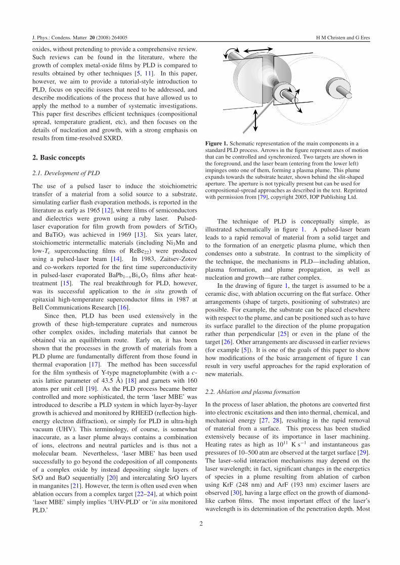
Figure 1. Schematic representation of the main components in astandard PLD process. Arrows in the figure represent axes of motionthat can be controlled and synchronized. Two targets are shown inthe foreground, and the laser beam (entering from the lower left)impinges onto one of them, forming a plasma plume. This plumeexpands towards the substrate heater, shown behind the slit-shapedaperture. The aperture is not typically present but can be used forcompositional-spread approaches as described in the text. Reprintedwith permission from [79], copyright 2005, IOP Publishing Ltd.
The technique of PLD is conceptually simple, asillustrated schematically in figure 1. A pulsed-laser beamleads to a rapid removal of material from a solid target andto the formation of an energetic plasma plume, which thencondenses onto a substrate. In contrast to the simplicity ofthe technique, the mechanisms in PLD—including ablation,plasma formation, and plume propagation, as well asnucleation and growth—are rather complex.
In the drawing of figure 1, the target is assumed to be aceramic disc, with ablation occurring on the flat surface. Otherarrangements (shape of targets, positioning of substrates) arepossible. For example, the substrate can be placed elsewherewith respect to the plume, and can be positioned such as to haveits surface parallel to the direction of the plume propagationrather than perpendicular [25] or even in the plane of thetarget [26]. Other arrangements are discussed in earlier reviews(for example [5]). It is one of the goals of this paper to showhow modifications of the basic arrangement of figure 1 canresult in very useful approaches for the rapid exploration ofnew materials.
2.2. Ablation and plasma formation
In the process of laser ablation, the photons are converted firstinto electronic excitations and then into thermal, chemical, andmechanical energy [27, 28], resulting in the rapid removalof material from a surface. This process has been studiedextensively because of its importance in laser machining.Heating rates as high as 1011 K s−1 and instantaneous gaspressures of 10–500 atm are observed at the target surface [29].The laser–solid interaction mechanisms may depend on thelaser wavelength; in fact, significant changes in the energeticsof species in a plume resulting from ablation of carbonusing KrF (248 nm) and ArF (193 nm) excimer lasers areobserved [30], having a large effect on the growth of diamond-like carbon films. The most important effect of the laser’swavelength is its determination of the penetration depth. Most
2

J. Phys.: Condens. Matter 20 (2008) 264005 H M Christen and G Eres
of the energy should be absorbed in a very shallow layer nearthe surface of the target to avoid subsurface boiling, whichcan lead to a large number of particulates at the film surface.However, the absorption of photons by oxygen molecules andoptical elements in the beam path determines a lower practicalwavelength limit of approximately 200 nm.
For relatively long pulse durations, such as the tens ofnanoseconds typical for excimer lasers, there is a stronginteraction between the forming plume and the incident beam,leading to a further heating of the species. This may explainexperiments of YBa2Cu3O7−δ film growth, where, for a givenlaser energy density at the target surface, ablation using a KrFexcimer laser (248 nm, ≈25 ns pulse duration) resulted infar superior films than ablation using a frequency-quadrupledNd:YAG (266 nm, ≈5 ns pulse duration) [31]. Similarly,certain aspects of a dual-laser approach [32], where a CO2
laser pulse with a 500 ns duration is allowed to interact withthe plume formed by the ablation using a KrF excimer laser,have been attributed to increased laser heating of the plasma.
Comparing PLD to pulsed-electron deposition (PED)reveals several interesting aspects of the deposition process. InPED [33–36], an electric discharge rather than a laser pulsecreates a plasma, and the energy density (integrated over thepulse duration) at the target surface is very similar to thatobtained in PLD. However, the pulse duration (100 ns) issignificantly longer. Compared to PLD, the PED processshows more significant deviations from stoichiometry, withstrong variations as a function of the position on thesubstrate [37]. This indicates the importance of a very denseplasma near the target surface in order to create a plume inwhich all species—regardless of their mass—expand with anidentical angular distribution.
Finally, the laser fluence at the surface of the target hasto exceed a certain threshold, which in many configurationsranges from 1 to 3 J cm−2 for a 25 ns pulse. A quitedifferent value of 0.3 J cm−2 has been found to be optimalfor the ablation of SrTiO3 from a single crystal (rather thanceramic) target in a background of 10−6 Torr (rather than thetypical 5–500 mTorr) and using a laser with a comparativelyfast rise time [38]. Even so, the required energies perpulse are fairly high and most readily achieved with excimerlasers [39]. Lasers using KrF excimers (248 nm, typically20–35 ns pulse duration) have been used most often in PLD,but successful film growth has also been achieved using ArF(193 nm) [40–42] and XeCl (308 nm) [43–47] excimers.
Many ‘ultrafast lasers’ deliver less energy per pulse, butwith a much shorter pulse duration (thus high instantaneouspower) and a higher repetition rate than excimer lasers. Forchemically less complex materials such as simple oxides(where stoichiometry is not an issue and thus the plasmadensity may not matter as much), film growth has indeed beenpossible using a variety of lasers, including hybrid dye/excimerlasers (248 nm, 500 fs) [48] and femtosecond Ti–sapphirelasers [49–51]. A 76 MHz, 60 ps mode-locked Nd:YAGlaser has been used successfully for the ‘ultrafast ablation’and growth of amorphous carbon [52]. More recently, similartechniques have been applied to the growth of more complexmaterials, such as Ge33As12Se55 [53], leading to optimism forthe use of these different lasers.
2.3. Plume propagation
Plume propagation has been studied extensively using opticalabsorption and emission spectroscopy combined with ionprobe measurements [29, 54, 55], and does not need tobe discussed in detail here. Neutral atoms, ions, andelectrons travel at different velocities, and strong interactionsbetween the species of the plasma and the background gasare observed. In fact, it is sometimes assumed that somedegree of thermalization needs to occur in order to obtain goodfilm growth and to avoid resputtering of the growing film bythe most energetic ions in the plume [56]. Assuming thatmost of the species in the plume should be fully thermalizedat precisely the time they reach the substrate (i.e. havingequal lateral and forward velocities), a simple model predictsthat the optimal growth rate should be close to 1 A perpulse [57, 58]. This is rather close to the actually observedvalues for many experiments, where stabilization of a complexmaterial is the main goal. However, the precise formationof superlattice materials, especially comprised of SrTiO3 andrelated perovskites, is often best achieved at much lowerdeposition rates (requiring hundreds of laser pulses per unitcell) [6].
2.4. Control of stoichiometry
The stoichiometric removal of material from a solid target isundoubtedly the single most important factor in the success ofPLD. For a vast majority of ceramic targets, and for ablationrates that result in a dense plasma as described above, theremoval of material does indeed preserve stoichiometry. Thisis particularly true after an initial ‘preablation’ process, i.e. theexposure of the target surface to the laser irradiation for sometime before deposition in order to obtain a steady state (which,if one of the elements is more volatile than others, resultsin an enrichment of the target surface of the less-volatilecomponent).
Stoichiometric removal of the material from the target,however, does not necessarily translate into the growth ofstoichiometric materials, as not all elements get incorporatedat the same rate (often referred to as a ‘sticking coefficient’),some resputtering can occur [56], and volatile elements mayre-evaporate from the growth surface. When growing materialscontain an element that is considerably more volatile thanothers, such as KNbO3 (with potassium being the more volatilespecies), the use of an additional source is often required. Thiscan be done, for example, by using a rotating segmented target,consisting of KNbO3 and KNO3—the latter being an additionalpotassium supply [59, 60]. Similarly, non-stoichiometrictargets are often used to compensate for the loss of Bi orPb. In all of these cases, it is generally observed that it ispossible to work in a regime of significant excess of the volatilecomponent, all of which re-evaporates beyond the amountneeded to form the stoichiometric compound.
For oxide materials, proper control of the oxygen contentis of paramount importance. The fact that PLD is possiblein a broad range of background pressures aids especially inthe formation of ferroelectric materials, for which no othermethod has produced better properties than those achievableby PLD [61, 62].
3
J. Phys.: Condens. Matter 20 (2008) 264005 H M Christen and G Eres
0.8
1.0
= 150O
0On
x
0.4
0.6 = 120O
= 90O
conc
entr
atio
n
-1.0 -0.5 0.0 0.5 1.00.0
0.2c
d/R
KTa1-xNbxO3
d/R
Constant Angular Velocity
α
αα
(a) (b)
(c)
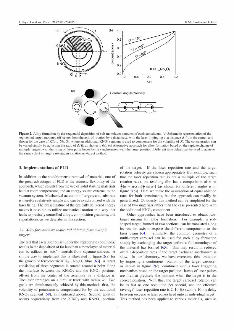
Figure 2. Alloy formation by the sequential deposition of sub-monolayer amounts of each constituent. (a) Schematic representation of thesegmented target, mounted off-center from the axis of rotation by a distance d , with the laser impinging at a distance R from the center, andshown for the case of KTa1−x Nbx O3, where an additional KNO3 segment is used to compensate for the volatility of K . The concentration canbe varied simply by adjusting the ratio of d/R, as shown in (b). (c) Alternative approach for alloy formation based on the rapid exchange ofmultiple targets, with the firing of laser pulse bursts being synchronized with the target position. Different time delays can be used to achievethe same effect as target rastering in a stationary-target method.
3. Implementations of PLD
In addition to the stoichiometric removal of material, one ofthe great advantages of PLD is the intrinsic flexibility of theapproach, which results from the use of solid starting materialsheld at room temperature, and an energy source external to thevacuum system. Mechanical actuation of targets and substrateis therefore relatively simple and can be synchronized with thelaser firing. The pulsed nature of the optically delivered energymakes it possible to utilize mechanical motion in a way thatleads to precisely controlled alloys, composition gradients, andsuperlattices, as we describe in this section.
3.1. Alloy formation by sequential ablation from multipletargets
The fact that each laser pulse (under the appropriate conditions)results in the deposition of far less than a monolayer of materialcan be utilized to ‘mix’ materials from separate sources. Asimple way to implement this is illustrated in figure 2(a) forthe growth of ferroelectric KTa1−x Nbx O3 films [63]. A targetconsisting of three segments is rotated around a point alongthe interface between the KNbO3 and the KNO3 portions,off-set from the center of the assembly by a distance d .The laser impinges on a circular track with radius R. Twogoals are simultaneously achieved by this method: first, thevolatility of potassium is compensated for by the additionalKNO3 segment [59], as mentioned above. Second, ablationoccurs sequentially from the KTaO3 and KNbO3 portions
of the target. If the laser repetition rate and the targetrotation velocity are chosen appropriately (for example, suchthat the laser repetition rate is not a multiple of the targetrotation rate), the resulting film has a composition of x =1π[α + arcsin( d
R sin α)] (as shown for different angles α infigure 2(b)). Here we make the assumption of equal ablationrates for both constituents, but the approach can readily begeneralized. Obviously, this method can be simplified for thecase of two materials rather than the case presented here withthe additional KNO3 component.
Other approaches have been introduced to obtain two-target mixing for alloy formation. For example, a rod-shaped target, formed of two sections, can be translated alongits rotation axis to expose the different components to thelaser beam [64]. Similarly, the common geometry of amulti-target carousel can be used for such alloy formationsimply by exchanging the target before a full monolayer ofthe material has formed [65]. This may result in reducedoverall deposition rates if the target exchange mechanism isslow. In our laboratory, we have overcome this limitationby imposing a continuous rotation of the target carousel,as shown in figure 2(c), combined with a laser triggeringmechanism based on the target position: bursts of laser pulsesare fired at precisely the moment when the target is in thecorrect position. With this, the target carousel rotation canbe as fast as one revolution per second, and the effective(average) laser repetition rate is 2–10 Hz (with a 10 ms delaybetween successive laser pulses fired onto an individual target).This method has been applied to various materials, such as
4

J. Phys.: Condens. Matter 20 (2008) 264005 H M Christen and G Eres
the ferroelectric Bi(Fe1−xCrx)O3 alloys [66], and its use inthe formation of vertical composition gradients (i.e. in thedirection of film growth) is a straightforward extension.
3.2. Continuous compositional spread
As mixing between targets results in the formation of alloymaterials, it is a natural extension of this method to combinethe mixing with a lateral translation of the substrate in orderto obtain spatial variations of the composition on a largersubstrate. Such an approach is motivated by the observationthat combinatorial materials science has enjoyed great successin the chemical and pharmaceutical industries, with successesin thin-film research still being comparatively rare. This isin part due to the great technical challenge involved in thecharacterization of the resulting materials. An approach forthe parallel multi-sample synthesis is therefore needed thatyields samples large enough for conventional measurementtechniques to be used, even if a smaller number of materialscan be simultaneously synthesized and studied.
Earlier implementations of combinatorial PLD ap-proaches [67–70] were based on the room-temperature deposi-tion of a precursor material, which is then converted to a com-plex perovskite in a post-deposition annealing process. Theadvantage of these discrete combinatorial methods—which arebased on the precise positioning of delicate masks—is the largenumber of compositions that can be synthesized, at the ex-pense, however, of a synthesis method that is fundamentallydifferent from the most successful implementations of PLD.Later versions of PLD-based discrete combinatorial methodshave been used for the formation of complex materials directlyat elevated temperatures [71–73]. Unfortunately, even for therelatively small number of compositions explored simultane-ously, the small substrate size still leaves the requirement ofspecialized characterization techniques.
One approach to obtain a laterally varying compositionacross a large substrate is to use the naturally observedspatial growth rate variations in PLD, similar to what hasbeen done already in sputter-based compositional-spreadmethods [74, 75]. This is in fact possible using PLD withsynchronized substrate motion and laser firing [76]. However,in addition to the growth rate, the energetics of the depositedspecies in PLD may also vary as a function of position on thesubstrate, and the method thus suffers from the simultaneousvariation of two parameters across the sample surface.
This difficulty can be overcome by inserting an aperturebetween the target and the substrate, as shown in figure 1.The combined translation of the substrate behind this apertureand the exchange of targets after deposition of less than amonolayer results in linear composition gradients. As we haveshown in [77], the position of laser ‘trigger points’ can becalculated such that a linear composition variation is obtainedsimply by firing the laser each time one of the trigger pointsis aligned with the center of the aperture. This producesa very stable and easy-to-implement approach, sending atrigger signal to the laser each time the heater position (oran encoder on the motor that drives the heater translation)coincides with one of these pre-calculated trigger points. The
oscillatory heater motion can then be chosen such as tooptimize its speed: in our configuration with a travel distanceof ∼50 mm, each pass requires approximately 1 s (requiring inmost cases effective maximum laser repetition rates between50 and 100 Hz). This method has been applied successfullyto the synthesis of complex transition-metal oxides, suchas alloys between paramagnetic CaRuO3 and ferromagneticSrRuO3 [77].
3.3. Controlling the lateral thickness variation
Just as repeated back-and-forth passes of the substrate behindthe aperture in figure 1 can be used to repeatedly deposit sub-monolayer amounts in order to form alloys, the method isreadily adapted to situations where simple thickness gradientsare desired. Such samples are important, for example, in thestudy of thickness effects on the properties of films. Themethod can also be used for entirely different applications:orthogonally overlapping wedges of metallic films can be used,for example, in the study of catalysis of carbon nanotubes [78].
Obtaining good thickness uniformity—rather than con-trolled thickness gradients—is often important, but impossibleby simply depositing onto a stationary substrate. Using againthe approach of synchronized laser firing and substrate posi-tioning, the uniformity can be controlled [79] either on largerwafers or on a row of samples as necessary for the temperature-gradient method described below.
3.4. Temperature-gradient approaches
The growth temperature is often the most critical parameterin any film deposition experiment. Determining the correctsubstrate temperature is therefore a necessary but time-consuming first step in the exploration of new materials. Inthe spirit of the above-described ‘multi-sample’ approaches, itis possible to deposit simultaneously onto multiple samples,each held at a different temperature. Such an approach wasfirst reported more than 40 years ago [80], but has onlyrecently been applied to complex oxides [81, 82]. In theserecent approaches, a large temperature difference (∼300 ◦C)is obtained across a 10 mm sample by the use of laser heating.Again realizing the importance of traditional characterizationtechniques, however, we have implemented an approach inwhich the temperature gradient is much smaller (a change of600 ◦C across a distance of 70 mm) [83]. Using samplesthat are typically 2 mm wide in the direction of the gradientand 10 mm long in the orthogonal direction, the temperaturedifference across each sample is about 15 ◦C. The approachthus provides sufficient temperature uniformity for initialstudies, and yields samples that are easily characterized usingtraditional x-ray diffraction or transport methods.
Figure 3 shows a schematic diagram of the method. Aradiative heater (based on a Pt-alloy heat element) is used toheat a metallic substrate holder, which is cut into a shape suchthat a protruding ‘finger’ results in local heat loss. Combinedwith additional shields and slots cut into this plate (not shown),a linear temperature variation, as shown in figure 3(b), isobtained. The method has been applied to the study of electro-optic materials [83] and the determination of crystallization
5

J. Phys.: Condens. Matter 20 (2008) 264005 H M Christen and G Eres
Figure 3. (a) Schematic representation of the substrate heater with ametallic plate yielding a smoothly varying temperature profile.Additional heat shields are added and temperature-isolating slots arecut into this plate (not shown). (b) Temperature variation across thesubstrate plate (filled circles, left scale) and obtained film thickness(open circles, right scale), showing satisfactory temperature linearityand thickness uniformity. Reprinted with permission from [83],Copyright 2004, American Institute of Physics.
temperatures of a series of rare-earth scandates as candidatehigh-k dielectric gate materials [84].
3.5. Superlattice growth
In section 3.1 above, we have shown that sequential ablationfrom separate targets can lead to alloy formation if much lessthan one unit cell is deposited in each cycle. The approach toform heterostructures and superlattices is conceptually similar,except that at least one ‘complete layer’ is grown beforedepositing the next material. Obviously, in order to forma true superlattice, the roughness of each interface must besignificantly smaller than the thickness of these layers. Aswe show below in the discussion of growth kinetics, this isa non-trivial requirement when the layer thickness decreasesto one unit cell. We use our SXRD data to show that currentunderstanding of nucleation and growth predicts that no growthmethod is capable of producing a completely full layer that isexactly one unit cell thick with true atomic-scale sharpness.The only possible exception is step flow growth, for whichin situ monitoring techniques fail.
Despite these fundamental considerations, the ease bywhich PLD allows us to alternate between different materialshas been used by numerous groups to apply the techniqueto superlattice growth. The simplest approach is to calibratethe growth rates for each material (in terms of the amountof material deposited per laser pulse) and then grow thesuperlattice by counting laser pulses [60, 85–88]. The useof RHEED makes it possible to track the number of layersdeposited in real time, as the intensity oscillates with a
periodicity equal to the time required for the deposition of amonolayer [89].
Superlattice peaks in x-ray diffraction scans are a clearindication that a periodic structure has been obtained; however,without actual calculation (numerical modeling) of the peakintensities, these data only demonstrate periodicity, notinterface sharpness. Z -contrast scanning transmission electronmicroscopy (STEM) has become a widely accepted andfrequently used tool to analyze interfaces, by visualizing aprojection of a specimen with a thickness of a few tens ofnanometers. Here, interfaces that appear atomically sharpwithin the limits of the technique [6, 90] have been observed.In fact, the quality of PLD-grown samples has now reached alevel that was previously thought to be achievable exclusivelyby MBE. As we mentioned above, steps in the substrate surfaceand the natural and unavoidable broadening of the electronbeam as it traverses the sample (dechanneling) currently makeit impossible to distinguish between a perfect atomically sharpinterface and a partially diffuse layer of a single unit cellthickness (most data presented in the literature show a width—apparent or real—of more than one unit cell). Surface x-raydiffraction is currently the only technique that can identify andprobe intermixing on a single unit cell level [91].
In order to understand the fundamental limits to atomicallysharp interface formation in current methods, and to determinehow to modify these methods to yield the desired perfectly flatlayers, we next turn our attention to basic considerations ofnucleation, island growth, coalescence, and layer filling, beforediscussing the new understanding gained from time-resolvedSXRD studies.
4. Simple models of nucleation and growth
4.1. Step flow and island formation
Most mechanisms in film growth are strongly materialdependent—the formation of an epitaxial perovskite filminvolves a different mechanism than the deposition of a goldlayer. For the purposes of this paper, we are concernedprimarily with the synthesis of epitaxial perovskite films at theearly stages of growth. Even though the precise mechanismsleading to the crystallization of these complex materials arestill unknown, it is illustrative to begin this section with a fewsimple and generic considerations. A more detailed descriptionof various growth models is found in [92].
The simplest possible model of film growth is that ofatoms landing on a surface, where they randomly select asite at which they remain immobile. If the probabilities of‘sticking’ are equal for all sites (including sites with nearestneighbors, and those on top of already-deposited species), thenthe deposition of N particles onto N sites (i.e. one monolayer)leaves 37% (=1/e) of the surface uncovered. Note that realsystems are quite different, and even an ideal ball model ona hexagonal lattice is fundamentally different, as there areno sites above a single adatoms. At any finite temperature,the picture of immobile balls changes: the deposited species(‘adatoms’) have a non-vanishing diffusivity D and thusremain mobile at the surface until they are immobilized when
6

J. Phys.: Condens. Matter 20 (2008) 264005 H M Christen and G Eres
S1 S2
L1 L2 L3
Figure 4. Step flow on a vicinal surface. Adatoms migrate either tothe left (‘up’) or to the right (‘down’) to be incorporated at a stepedge.
they encounter an energetically favorable site. In the absenceof extrinsic nucleation sites (e.g. defects in the substratesurface), the sites at which adatoms become immobilized arethose that increase their atomic coordination, which leadsto adatom incorporation at steps and to the formation ofan island wherever two adatoms meet. Therefore, speciesdeposited on top of an existing layer have a strong tendencyto transfer to the next lower level by a mechanism knownas interlayer mass transport [93]. Depending on the typeof bonding, the probability of this transfer over a step edgemay be reduced by the energetically unfavorable position ofan adatom at the step edge, leading to a so-called Ehrlich–Schwoebel (ES) barrier [94, 95]. A very large ES barrierwould immediately lead to three-dimensional (3D) growth, asvoids (or holes) in each layer would only be filled at a rate of(1 − 1/e) per deposited monolayer. While it is conceptuallyeasy to understand the formation of an ES barrier for casessuch as the growth of noble metals, there are argumentsagainst such a barrier for more complex systems, such ascompound semiconductors [96]. The frequently observed two-dimensional growth habit of complex oxides, such as SrTiO3,by a variety of techniques, argues against a behavior dominatedby an ES barrier for these materials.
A realistic surface will always exhibit step terraces spacedon average at L ≈ a/α, where α is the miscut angle of thesubstrate (in radians) and a is the material’s lattice parameter.In the case of low deposition flux F and a high diffusion rate(i.e. for large values of D/F), adatoms will have a tendencyto migrate to the step terraces without nucleating islands. Theresulting step flow is illustrated in figure 4. Adatoms can attachthemselves to the steps on the left or the right of the terracewith probabilities κL and κR, respectively. The steps S1 andS2 therefore travel with velocities v1 = κL F L2 + κR F L1
and v2 = κL F L3 + κR F L2. In the absence of a ES barrier,κL = κR = κ . In this case, step flow is unstable againstperturbations: if we let L1 = L + �L, L2 = L − �L,and L3 = L, then v1/v2 = 2L/(2L − �L) > 1. In otherwords, the larger terrace grows faster than the narrower one,eventually leading to so-called step bunching. In contrast,a large ES barrier (such that κR ≈ 0) stabilizes step flow.It needs to be pointed out that in the case of heteroepitaxyepitaxial strain also leads to step bunching [97], as has beenconfirmed by the careful comparison between experiments andcalculations [98, 99].
PLD differs from other physical vapor deposition methodssuch as MBE and sputtering in two important ways: first, theprocess is pulsed, meaning that a finite amount of materialis deposited in a short time, namely the time of the plume
interaction with the substrate. In contrast to the laser pulse,which lasts no longer than 30 ns even with excimer lasers,the plume interacts with the substrate for a few microseconds.Second, the energies of the impinging species in PLD are largeand spread broadly with a typical mean energy of a few eV,while MBE provides a much more uniform energy distributionand energies of a few tens of an eV.
Some aspects of the energetic nature of PLD can be treatedby considering an effective diffusivity D′, which may differfrom the single-atom diffusivity and take into considerationcollision-induced detachment from forming islands and othereffects described below. The average deposition flux can bewritten as F = Np/τ , where Np is the amount of materialdeposited per pulse and τ is the time between pulses. Withthis notation, the requirement for step flow (namely that thetime between laser pulses is large compared to the lifetime ofdiffusing atoms on a terrace) becomes F < 2Np D′/L2 [98].In other words, whether or not step flow occurs depends notonly on the diffusivity and the deposition rate, but also on theoriginal miscut of the substrate.
For the growth of smooth, uniform layers, step flow isclearly the preferred growth mode, as there are no issuesregarding complete layer filling, nucleation of islands on topof existing islands, or even incorporation of defects at points ofcoalescence between islands. However, there are no periodicchanges in surface characteristics that can be tracked in orderto monitor in situ the growth and to terminate growth aftercompletion of a predetermined number of layers. Therefore,for the synthesis of precise superlattice structures, ideal LBLgrowth is required. In light of this requirement, we now turnour attention to nucleation and growth of islands.
4.2. Nucleation and island growth
Acknowledging that epitaxial film growth derives virtuallyall of its utility from the possibility of heteroepitaxy, wenevertheless limit the following discussion to the special caseof homoepitaxy. The homoepitaxial model system allows usto focus on pure kinetics in the formation of atomically sharpinterfaces without interference from such issues as interfacialdiffusion, strain relaxation by defect formation, and more thanone material-specific surface free energy.
We start by considering the importance of the pulsednature of the process. The question of energetics in themechanism of PLD will be addressed later. In the simplestmodel, one assumes that whenever an adatom encountersanother adatom as its nearest neighbor both atoms stopdiffusing and nucleate an island. The number of islands growsquickly within the deposition of as little as a few per cent of amonolayer, after which it changes insignificantly [100]. This issimply a consequence of the fact that the adatom density at thesurface is reduced (at fixed flux) as the step edge and islanddensities increase. Simply put, the adatoms become morelikely to encounter an existing island than another diffusingadatom after deposition of a few per cent of a monolayer. ForPLD, this implies that the number of nucleation sites saturatesafter the first laser pulse. Consequently, additional materialwill attach itself to the existing islands, the number of which
7

J. Phys.: Condens. Matter 20 (2008) 264005 H M Christen and G Eres
Figure 5. Top view of film growth in a simple view of nucleation, island growth, and coalescence. (a) Nucleation of islands with acharacteristic spacing, λ. These islands form layer n + 1 on top of the previous surface (layer n). (b) Growth of islands leads to coalescencewhen the typical island size becomes comparable to λ. (c) Nucleation of the next layer (n + 2) on top of the islands (layer n + 1) begins whenthe island size is comparable to or larger than the nucleation site spacing, λ.
essentially remains unchanged at least until coalescence ofislands occurs. We will show below that ripening, i.e. theprocess by which larger islands grow at the expense of smallerones, is undesirable. In contrast, any mechanism that resultsin the formation of additional islands without increasing thenucleation density (i.e. breaking up of existing islands intosmaller ones) would delay the formation of a second growthlayer.
Figure 5 shows schematically the steps involved in theformation and growth of islands. Initial deposition (i.e. the firstlaser pulse) leads to the nucleation of islands at a characteristicspacing λ. Various mechanisms influence the value of λ,most importantly D and F . Other factors may also play arole, such as the energetics of the impinging species or anadditional energy source such as an added ion beam. Forsimplicity, we will only consider the case of islands thatremain essentially immobile once they reach a critical sizeof a few atoms. An important point to remember whenconsidering how to change the growth mode is that λ < Lmust be satisfied to avoid step flow. Deposition of additionalmaterial then results in the growth of these islands, initiallywithout nucleation of new islands either on top or betweenthe existing ones in the ideal case of a negligibly small ESbarrier. The island size remains below λ until the pointof coalescence. The very definition of λ implies that newislands do not nucleate on an island with diameter 2R < λ.Whether additional adatoms (or, in the case of perovskite,entire building blocks) formed on top of an island insertthemselves by migration to the island edge or by lateralpushout of material is irrelevant in the earlier stages, where nosecond-layer nucleation is expected. In later stages, i.e. whenthe islands are relatively large, insertion anywhere other thanthe island edges will become energetically unfavorable. Ifdeposition proceeds under unchanged conditions, new islandswill invariably nucleate on top of the existing ones as soon asa critical island size is reached [101], i.e. when coalescence isreached at R ≈ λ/2. This leads to the unavoidable formationof a two-level growth front. The ideal case of LBL growth,where one layer is completely filled before nucleation of newislands, is therefore not observed [101].
Again, it is important to remember that we are concernedhere with growth outside the step flow regime. Ideal LBLgrowth can thus not be achieved by increasing the adatom
mobility (perhaps by using high-energy impinging species),which would promote step flow. It is nevertheless interestingto note that high cluster mobilities have been proposed as apossible origin of enhanced growth kinetics in PLD [102].
The time-dependent distribution of adatoms on thegrowing surface is a key difference between MBE and PLD. Infact, while we would assume unchanged conditions during anideal pulsed process such that the adatom concentration on topof the islands is identical to that between them, this is not thecase for MBE: there, the edges of each terrace act as a drain,and in a steady-state process the adatom concentration on anisland is smaller than on an infinite surface [103]. This clearlyaids in minimizing nucleation on top of existing islands. In apulsed process, if the deposition occurs on a timescale that isshorter than that corresponding to the motion of the adatoms,no such self-limiting mechanism exists—the adatom densityon top of an island is very close to that responsible for the initialnucleation at a characteristic distance, λ. We will return to thisissue later when we show that the success of PLD is relatedto the fact that interlayer transfer (motion of material from thetop of an island to the layer below) occurs largely at timescalescomparable to the plume duration.
4.3. Ripening and island shape
It is clear from the above consideration that ripening leads tolarger islands at the same surface coverage. It is undesirable inLBL growth because nucleation of the second layer becomesfavorable at an earlier stage of growth [104]. Of course, someripening is expected to occur in all processes where detachmentof an adatom from an existing island is possible.
The picture of circular islands, as schematically drawnin figure 5, is a simplification that we have made withoutspecial justification. In fact, in the simple model mentionedabove of adatoms ‘frozen in place’ as soon as they encounteranother adatom, the shape of islands is anything but circular:numerical simulations indicate the formation of dendriticgrowth patterns [100]. Such growth patterns would beadvantageous, since for a given fractional coverage of thesurface, the path from any point on top of an island to anavailable edge site is, on average, smaller than in the case ofcircular islands.
During the early part of a monolayer deposition, mostof the island growth occurs via migration of adatoms on the
8

J. Phys.: Condens. Matter 20 (2008) 264005 H M Christen and G Eres
initial surface towards the edges of the islands (rather thanby interlayer transfer down from the second level). It istherefore easy to assume that the edges of each island indeedfirst assume a somewhat dendritic (or fractal) shape (assumingthat the timescale for diffusion of an individual adatom beforeattachment to an edge is short as compared to that requiredfor diffusing along a step edge). The island contours thensmoothen during the time between two laser pulses. Such asmoothening process will reduce the density of step edges, andresult in a recovery of the RHEED signal transients that occurat each laser pulse. Clear evidence of the formation of smoothcontours comes from ex situ AFM observations of growthsurfaces, which are often dominated by isotropic islands.
A thermally driven process that reduces the step edgedensity for a given surface coverage clearly hinders ideal LBLgrowth. One way to avoid this mechanism is to reduce thetime between laser pulses, which, for example, can be achievedin a method termed ‘pulsed-laser interval deposition’ [105].Here, the amount corresponding to exactly one monolayer israpidly deposited, followed by a pause during which some‘annealing’ of the surface is allowed. Deposition energeticsmay also play an important role. Aziz and co-workershave performed careful comparisons between MBE-grown andPLD-deposited metal and semiconductor films, using variousPLD conditions [106, 107]. As the pulsed nature of PLD byitself is insufficient to explain the observed behaviors, energeticeffects are found to be important in determining the evolutionof surface morphology. Similarly, the effect of energeticspecies in removing adatoms that were attached near the edgesof a growing island has been considered [108]. A model inwhich impinging species break up existing small islands isfound to be compatible with SXRD data in heteroepitaxialgrowth [109]. Similarly obtained data have also been explainedin terms of a non-thermal smoothing mechanism, even in anexperiment where growth evolves beyond a two-level systemafter the deposition of a few monolayers [110]. The preciseanalysis of the growth front evolution, however, can only beachieved by quantitative measurements of layer coverages, towhich we now turn our attention.
5. Monitoring of growth kinetics
5.1. Introduction and RHEED studies
In ideal superlattice growth it is not only assumed that thestarting surface is prepared atomically flat, but switching fromone material to the next is performed exactly at the top of aRHEED oscillation—the supposition here is that the growinglayer is complete. However, numerous examples show that thisassumption is almost never fully justified. Here we use theresults of recent growth kinetics studies to examine this issuein more detail.
We start this discussion by noting that the RHEED oscilla-tion maxima do not correspond to layer completion [111]. Thisis not a serious problem when RHEED is used for counting lay-ers or determining growth modes. However, as the number oflayers becomes smaller this fact must be recognized and prop-erly accounted for. Rigorous consideration of this subtle effect
is particularly important in growth kinetics studies. RHEEDoscillations (or intensity oscillations in other diffraction tech-niques) are associated with the periodic nature of the layerfilling process that occurs when growth proceeds in a cyclicfashion. Such a cyclic process does not, however, necessarilyimply ideal LBL growth, but can occur in the form of over-lapping two-layer growth as described below (analogous to thetwo-layer behavior observed under sputter removal of mate-rial [112]). Only in perfect LBL growth do these oscillationshave a maximum intensity equal to the starting intensity whenthe layer is full and minimum intensity when the layer is halffilled.
Simple arguments concerning nucleation, growth, andcoalescence, developed by Comsa and co-workers inconnection with metal MBE, show why the maximum intensityin diffraction measurements never again reaches its startingvalue [10]. The intensity maxima occur at the point whenmore atoms remain in the top islands than are added to thebase islands. The value of this maximum is always lessthan the starting intensity because even if the base layer iscomplete—which is almost never the case—there are alreadyislands on top of the base layer that reduce the intensity. Thesituation becomes more complex if the base layer filling isslow and the requirement for nucleation of a new layer ontop of the growing layer is satisfied before the base layer iscomplete. This interface broadening requires that the turningpoints in the intensity oscillations (minima and maxima) nowbe determined by adding up the contributions from all theopen layers. Of course, the intensity envelope continues todecay as the interface broadens, with the extreme case beingthree-dimensional (3D) growth that eliminates all intensityoscillations.
If the supply of atoms is interrupted in LBL growth, theresponse of the surface in filling the open layers results in arecovery of the intensity toward the initial value. This recoverywas observed first in GaAs, and was found to consist of twosteps with distinctly different time constants [113]. Afterconsiderable debate a consensus emerged that the initial rapidstep corresponds to filling of holes by atoms transferring intothe base layer, and the long time constant step correspondsto ripening of the remaining islands [114]. However, it mustbe noted that this simple picture is significantly altered in thepresence of an ES barrier that impedes the transfer of atomsfrom the top layer into the base layer (see section 4.1 above).
It is naturally tempting to think of PLD as an opportunityto study the mechanisms associated with the recovery in oxidematerials by using time-resolved measurements: in a simplistic(and, as we will show, inaccurate) view, deposition occurson a fast timescale determined by the arrival of the speciesin the plume, and growth occurs after these species arrive onthe surface, nucleate islands or diffuse around in search of theproper crystallographic lattice sites. Detailed measurements ofthe time constants would then provide important clues for theidentification of the possible mechanisms involved. In earlyRHEED intensity oscillation measurements the amount ofmaterial deposited per pulse was too small to cause modulation(steps) in the RHEED oscillations. In contrast to GaAs, inPLD of SrTiO3 [89] and YBa2Cu3O7−x (YBCO) [115] only
9

J. Phys.: Condens. Matter 20 (2008) 264005 H M Christen and G Eres
a single-step recovery was observed after growth termination.This recovery was attributed to a reduction of the step edgedensity by surface rearrangements that results in the formationof larger islands.
True time-resolved measurements of the recovery aftersingle laser shots became possible with the ability to increasethe amount of material deposited per pulse. Using time-resolved RHEED intensity oscillation measurements in YBCOPLD, single shot recovery was observed but only in the lastshot before the peak of the oscillation period (assumed to benear full coverage) [116]. The temperature dependence ofthe time constants (ranging from 0.2 to 0.4 s) would allowattributing the recovery to crystallization of the depositedmaterial, a process fundamentally different from the previousinterpretation of step edge density reduction. Complicatingthe unambiguous identification of the responsible mechanismis the fact that observation of fast processes associated withthe plume arrival by RHEED is difficult, primarily because theacquisition time is limited to 30–100 ms by the CCD framecapture rate. A first indication of a fast recovery processwas observed during growth mode studies of SrTiO3 thatmapped a wide range of substrate temperatures and depositionconditions [117]. This work observed only partial recovery ofthe RHEED intensity, but systematically measured the slowrecovery stage. Additional scanning tunneling microscopydata confirmed that the recovery was related to slow surfacemigration.
5.2. Growth kinetics studies by surface x-ray diffraction
RHEED is not an ideal tool for growth kinetics studies becausethe strong interaction of the electrons with the surface causesmultiple scattering and requires dynamical theory for rigorousinterpretation of the intensities [111, 118]. In contrast, theabove-mentioned intuitive and widely used step edge densitymodel emerged from empirical correlation between STMimaging of step density and RHEED intensity [119, 120]. Asan alternative technique, SXRD has the unique advantage thatkinematic scattering is applicable and that the intensity can beinterpreted directly in terms of surface coverage [121, 122].Time-resolved SXRD at crystal truncation rod (CTR) positionsallows real-time measurements of interface layer formation,so the combination of SXRD and PLD represents a powerfultechnique for gathering unique information on interfaceformation and growth kinetics [123–125]. X-rays also haveunique practical advantages. The ability of x-rays to avoidsurface charging makes x-ray diffraction the most suitabletechnique for studying oxide surfaces and interfaces [126].Unlike electrons, x-rays are not scattered by the high pressurebackground that is often necessary in oxide growth and donot interact with the surface to chemically perturb or alterthe growing film [127]. Finally, the static surface structureof SrTiO3 has been studied previously by measuring crystaltruncation rods [128, 129] to provide background informationon the state of the starting surface.
The scattering conditions in our SXRD experiments areset to monitor the formation of SrTiO3 unit cells. Thescattered intensity is measured simultaneously at the specular
Figure 6. Single laser shot time-resolved SXRD transients at the(0 0 1
2 ) specular rod. The top curve showing a drop corresponds to alaser shot following the growth intensity oscillation maximum, whilethe bottom curve showing a jump corresponds to a laser shotfollowing a growth intensity oscillation minimum. Each curverepresents an average of ten laser shots. The full oscillations areshown in figure 8. A logarithmic timescale, which spanned from 1 sbefore the laser shot to 10 s after, was used to capture the SXRDtransient. As a point of reference, the transients immediately after thelaser shot were captured using a sampling time of 6 μs, and the dataare shown binned to 25 μs. Note that because of the logarithmic timesampling the statistical fluctuations of the data appear exaggerated atshort sampling times. The dashed lines correspond to the x-rayintensity before the laser shot and the vertical solid line marks thetime when the laser was fired. Reprinted with permission from [121],Copyright 2006, American Physical Society.
(0 0 12 ) and off-specular (0 1 1
2 ) CTRs before, during, andafter PLD growth of SrTiO3. The significance of measuringboth rods is that the specular rod has momentum transferalong the surface normal and provides information only aboutdeposition, i.e. the height distribution of material. The lateralordering on the surface, and in-plane registry with the latticethat is synonymous with crystal growth, is confirmed bymeasuring an off-specular rod (h, k) �= (0, 0) which hasan in-plane momentum transfer component. Well developedand persistent RHEED-like SRXD growth oscillations areobserved simultaneously at both specular and off-specularCTR positions during homoepitaxial growth of SrTiO3 attemperatures ranging from 310 to 780 ◦C [130].
New experimental capabilities enable the measurementof SXRD transients with 10 μs time resolution [121]. Theability to measure the crystalline layer formation on the sametimescale as the plume arrival time reveals new details thatadvance our understanding and change the traditional viewof how PLD works. These fast measurements are madepossible primarily by the high brilliance of a third-generationsynchrotron x-ray source at the advanced photon source [131].A critical factor that enables taking full advantage of thehigh intensity is the perfection of the initial surface. Wedeveloped a highly selective screening process for choosingthe substrates used in the SXRD growth experiments—yielding one usable substrate out of every three after annealingand AFM inspection. The specular rod intensity at thetypical growth temperature (620–650 ◦C) is of the order of106 counts s−1. The value of the initial SXRD signal is a
10

J. Phys.: Condens. Matter 20 (2008) 264005 H M Christen and G Eres
good predictor of the film growth quality as judged by thepersistence of the intensity oscillations after initial decay.
The high-resolution SXRD transients in figure 6 showthat the fast stage in PLD cannot be resolved even witha microsecond range time resolution. These measurementsindicate that crystallization and—as we explain below—a largefraction of the total observed interlayer transport occur on thetimescale of the plume arrival, much faster than previouslyknown from using RHEED and SXRD [110, 130, 132].Thus, contrary to the simplistic picture mentioned above,deposition and growth (crystallization) cannot be separatedby the pulsed nature of the PLD process [121]. Surfacemigration preceding crystallization would manifest itself as atemperature-dependent time delay between the fast steps in thespecular and the off-specular transients [133].
5.3. Quantitative measurements of time-dependent coverages
In previous work both RHEED and SXRD growth intensityoscillations were analyzed using transport models [110, 130].On a qualitative level these models provide a clear illustrationof the importance of interlayer transport, and give invaluableclues for understanding the characteristic features of the SXRDtransients in terms of interlayer transport [111]. We considerthese models here despite the number of examples showingthat they do not fit the experimental data. It can be shown insimple terms that for a two-level system the diffraction signal ismost sensitive to interlayer transport near full coverage [111].The rate of interlayer transport in the recovery is given bydθ2/dt = kθ2(1 − θ1), where θ1,2 are the coverages in layers1 and 2, respectively, and k is the interlayer transport rateconstant. This differential equation can be solved to determinethe recovery for each particular value of the initial coverageθ1. Approaching full coverage, the (1 − θ1) term dominatesthe recovery because fewer holes remain in the base layer thatcan be filled. The important conclusion from the analysisof the simplest possible model is that the appearance of therecovery signal is affected not just by the time constant but bythe coverage at which the recovery is observed.
The key advantage of SXRD is that it enables quantitativedetermination of the coverages directly from the measuredintensity without specific assumptions about the physics ofthe growth process such as, for example, the shape of theislands. The use of the kinematic approximation enablesstraightforward calculation of the scattered intensity withincertain constraints that are determined only by the number ofincomplete layers during growth. It can be shown that forone or two layers on top of the substrate—islands on top ofa substrate, or islands on top of a base layer with holes—the intensity change from material distributed between theselayers can be calculated exactly [121]. For more than twolayers there are an arbitrary number of possibilities. In contrast,RHEED intensities must be calculated in terms of step edgedensity [111, 134]. This calculation requires assumptionsabout the shape of the islands to account for how the stepedge density changes with coverage. Note that the specularlyscattered x-ray intensity depends only on the number ofscatterers and is independent of the shape of the islands.
The validity of the assumptions for calculating thecoverage from the SXRD intensity, namely that no morethan three levels need to be considered, was confirmedby systematic AFM imaging of the substrates before andimmediately after film growth. Figure 7 shows an AFM imagethat illustrates the quality of the film surface observed afterfilm growth. In addition to showing the raw image, which atfirst appears to show only random noise on the data obtainedwithin a single terrace, we use a special coloring scheme inwhich each solid color represents a one-unit-cell step to convey‘what the x-rays are seeing’. The interface width is also plottedas a height histogram. The FWHM of the starting surfaceis typically around 0.2 nm. Interface roughness shows up asbroadening of the histogram and the appearance of tails thatextend past 0.2 nm on both sides, indicating the presence ofholes and islands on the surface. This clearly illustrates thatthe data are consistent with a three-level (two-layer) model andexcludes the possibility of roughening beyond these two layers.The interface broadening after film growth was compared withthe starting surface for the same substrate for numerous growthruns. There is a clear correlation between the persistence ofthe intensity oscillations and growth front broadening observedby AFM imaging. Samples that exhibit persistent intensityoscillations show minimal or no measurable growth frontbroadening compared to the substrate, and many samples showsurfaces that are significantly smoother than that shown infigure 7, occasionally exhibiting a narrower height histogramof the starting surface.
Instead of using a transport model to fit the data, the time-dependent coverages are calculated directly from the SXRDintensities [121]. At each point, the fractional coverage θn(t) =(√
I (t) + 1 + 2η(t))/4 of layer n is calculated directly fromthe normalized intensity I (t) and the deposited amount ofmaterial η(t) = θn(t) + θn+1(t), which increases with eachlaser pulse by a fixed step height. Without making any furtherassumptions, this method will properly distinguish betweentrue layer-by-layer growth and a three-level system.
The corresponding time-dependent coverages shown infigure 8 resemble a rising staircase, with each step having aunique shape. The shape within each staircase step indicateswhether net interlayer transport occurs into or out of thelayer and roughly falls into three categories. An ideally flatshape indicates no net interlayer transport and occurs near 0.5coverage. A slightly upward curving step indicates interlayertransport into the layer and occurs above 0.5 coverage. Aslightly downward curving step indicates interlayer transportout of the layer and occurs below 0.5 coverage. The curvatureof the non-flat steps becomes more pronounced with increasingdwell time between successive laser shots, serving as aqualitative indicator of the rate of interlayer transport.
In perfect LBL growth, coverage of layer n would reach100% before layer n + 1 nucleates, which is clearly notobserved. Nevertheless, by the time θn+1 reaches a value of,for example, 0.3, the layer below is more than 90% complete(θn > 0.9): the surface at this point consists primarily ofislands on a base layer having a few holes. Nucleation ofthe next layer always begins before completion of the previousone, which means that a truly atomically flat growth surface is
11

J. Phys.: Condens. Matter 20 (2008) 264005 H M Christen and G Eres
beforegrowth
aftergrowth
-0.4 -0.2 0.0
HEIGHT (nm)
0.2 0.4
Figure 7. AFM image that illustrates the range of surface morphologies observed in the three-level growth mode. To eliminate the possibleinfluence of terrace steps when leveling the raw AFM image, the scans were performed on a single terrace as designated by the yellow square.The dashed line in the histogram shows the surface width of the substrate, and the solid line that of the film. A color/greyscale scheme shownin the histogram was used to convey what the x-rays are ‘seeing’ at the anti-Bragg condition by setting solid color changes to occur at one unitcell heights. The image was obtained from a film that was more than 100 unit cells thick, and grown with a 50 s dwell time.
Figure 8. Oscillations. Ideal layer filling in pulsed mode is compared with actual PLD growth of STO at 0.2 and 50 s dwell time. Theintensity oscillations are shown in the top row, and the time-dependent layer coverages are given in the bottom row. Note the apparentsimilarity between one full period of actual growth (center part of (b) and (c)) with ideal LBL growth shown in (a). Interlayer transport ismanifested in the subtle features in which the real data departs from ideal behavior. The time-dependent coverages extracted from the singleshot transients are given in (e) and (f). Along a full set of layer filling data in the middle, layer filling near completion is given in the top curveand the onset of growth is shown by the bottom curve. Compare the ideal staircase in (d) with the actual data in (e) and (f) to see the curvaturechange near layer filling and at the onset of growth. Adapted from [121].
12

J. Phys.: Condens. Matter 20 (2008) 264005 H M Christen and G Eres
never observed. Further evidence of this behavior is obtainedfrom the analysis of diffuse x-ray scattering [135], whichshows a gradual increase in the characteristic length scales onthe surface: the system indeed maintains a ‘history,’ whichwould not be the case in homoepitaxy if perfect surfaces wereformed.
The significance of the single shot time-dependentcoverages is that they can be used to determine for each lasershot the amount of material that is transferred during the dwelltime between laser shots. These coverage changes can beused for constructing a picture about the role of the thermallydriven slow interlayer transport process in SrTiO3 PLD, i.e. themechanisms that occur within the experimentally resolvedtimescales above 25 μs. This thermally driven interlayertransfer occurs in addition to a fast (and experimentallyinaccessible) component. The plot in figure 9 shows theamount (in terms of coverage) of material transferred by theslow process from the top of the islands into the base layer asa function of coverage in the base (growing) layer. Data areshown for dwell times of 0.2 and 50 s between consecutivelaser pulses. Below half-coverage, no material remains ontop of an island (otherwise, strong roughening would occurimmediately and our three-level model would fail), implyingcomplete interlayer transfer into the layer below the island.However, just above half-coverage, the slow interlayer transferis still negligibly small, not reaching its maximum value untila coverage of about 0.7 is reached. The value at the maximumof the curves gives the largest fraction of the coverage thatwas transferred by this slow process. For example, at thepeak in the data obtained with a 50 s dwell time, a coveragechange of 0.02 can be attributed to this slow process. Ona per shot basis, this corresponds to 20% in the presentcase since there are 10 shots per monolayer. For a dwelltime of 0.2 s, however, this value falls to 5% for a 0.2 sdwell time [121]. This is a singularly important trend forpractical film growth because it shows that at typical PLDrepetition rates of few Hz the fraction of thermally driveninterlayer transport is small (albeit not entirely negligible).Most importantly, there is no significant distinction betweenthe coverage results obtained for different dwell times, whichmeans that the thermally driven interlayer transfer is notthe dominant mechanism leading to smooth film growth,nor is it a necessary component. Similar behavior with anabsence of recovery was observed in Ge PLD [136], promptingan interpretation that non-equilibrium laser driven processesoccurred on the same or a shorter timescale than the arrivalof the laser plume. Remembering that a study of the fast stepdiscussed above has already established that crystallization inSrTiO3 occurs on a timescale of microseconds, it is clear thatthe fast interlayer transport component must be the basis ofany growth kinetic manipulation method aimed at obtainingatomically sharp interfaces. Another argument in favor ofthis view is that the thermally driven interlayer transportcomponent is a difficult to control slow process, and mostimportantly its effects on interface broadening are largelyunpredictable because the phenomenon is not well understood.
Figure 9. A comparison of thermally driven interlayer transport at afixed temperature and dwell times of 50 s (solid dots) and 0.2 s(diamonds) plotted as a function of the coverage in the base layerinto which the transport occurred. The deposition rate is 0.1 unit cell(uc) per pulse. The dashed Gaussian lines are guides to the eye. Thepeak corresponds to the maximum amount of thermally transferredmaterial, which is 0.02(uc)/0.1(uc) = 20% of a single shot at 50 sdwell time, and less than 5% at 0.2 s dwell time. Adaptedfrom [121].
5.4. Kinetic growth manipulation
In this section we describe kinetic growth manipulation asa method for obtaining atomically sharp interfaces. Simplystated, the goal of kinetic growth manipulation is to achievenear-perfect LBL growth by delaying the nucleation of islandson the top of the growing layer for as long as possible (ideallyuntil the growing layer is complete) [137]. The PLD processhas been studied extensively and various approaches have beenexplored to reach this goal, which would manifest itself bycomplete recovery of the RHEED intensity after each unit celldeposition. Even in the more elaborate techniques, such as thepreviously mentioned ‘interval deposition’ approach [105], thishas not yet been achieved.
Our discussion of the time-resolved SXRD data illustratestwo features that are contradictory to conventional wisdomregarding PLD: first, crystallization occurs in the first fewmicroseconds after arrival of the deposited material, i.e. duringthe plume/substrate interaction (of course, some processesleading to a low defect density will still occur between laserpulses, but they are more akin to sintering mechanisms thanto crystallization). Second, the most important componentof interlayer transfer also occurs during the plume/substrateinteraction. The slower (thermal) mechanisms of interlayertransfer, which also lead to ripening and island growth, aretherefore not only undesirable, but also unnecessary.
The unique advantage of PLD as a tool for kinetic growthmanipulation comes from the extremely large dynamic rangeof the instantaneous growth rates [5]. By simply adjusting thelaser parameters, the growth rates in PLD can be varied overseveral orders of magnitude. As the island density and thecharacteristic nucleation length scale change inversely with thedeposition rate, this ability to vary the characteristic nucleationlength scale enables a different scheme for growth kineticmanipulation: the interlayer transport can be controlled inthe critical stages of the layer filling process according to thegrowth kinetic picture discussed above.
Methods to manipulate growth by modulating thenucleation density have been discussed previously for the case
13

J. Phys.: Condens. Matter 20 (2008) 264005 H M Christen and G Eres
of metal epitaxy [138]. The power law dependence of islanddensity on deposition flux renders the method rather inefficientin many techniques. In PLD, however, the growth rate isreadily modulated by orders of magnitude simply by varyingthe parameters of the laser spot on the target. Therefore, thefirst step in an efficient growth manipulation scheme is toinduce nucleation of a high density of islands with the firstlaser shot. This creates a large number of small islands that areclose to each other. The tendency of islands to ripen during thetime tc from island nucleation to coalescence limits the optimalisland density to ∼1/λ2 ∼= 1/Dstc, where Ds represent thesurface diffusivity. As Ds depends on temperature, even in thehighly non-equilibrium PLD growth technique, the nucleationlength scale depends on the substrate temperature. However,the fact that both interlayer transport and crystallization occuron a microsecond timescale (i.e. orders of magnitude fasterthan tc) allows us to suppress the thermally driven processessimply by increasing the growth rate.
Therefore, once the island density is set by the first laserpulse, the thermal processes that would lead to ripening mustbe minimized by rapid layer filling. However, the depositionper pulse must be maintained such that the critical nucleationlength is always larger than the island size. As we havediscussed, nucleation of new islands on top of the growingislands cannot be totally avoided after coalescence, but itcan be substantially reduced by maximizing the characteristicnucleation length scale. Realization of this step requires asubstantially reduced amount of material deposited by eachlaser pulse necessary to complete the layer. Note the importantdistinction between total growth rate (which must be high suchas to avoid ripening) and growth rate per pulse (which must below so as to minimize nucleation of new islands).
Therefore, the observation that ‘pure’ PLD is essentiallya process in which deposition and crystallization occursimultaneously (with some undesired thermal processes takingplace between laser pulses) allows us to postulate the followingrecipe for optimized growth: the nucleation density can beset during a first pulse (with parameters chosen such as tomaximize the amount of material deposited during the firstpulse). The remainder of the layer is then grown underconditions where each laser pulse deposits a significantlyreduced amount of material, while the deposition rate is kepthigh by increasing the laser repetition rate.
6. Conclusions
Pulsed-laser deposition has been tremendously successful inthe synthesis of complex-oxide materials. As we haveshown in this review, the process is easily adapted to abroad range of specialized methods, including the formationof alloys, compositional spreads, and superlattices. Theanalysis of physical properties arising at interfaces (and thus insuperlattices) is often based on the assumption of atomicallyflat junctions between dissimilar materials. Consistent withearlier studies on epitaxial growth, our analysis shows thatthe required perfect layer-by-layer growth is never achieved.However, careful analysis of our time-resolved SXRD datademonstrates an important property of PLD that renders this
method particularly suitable for obtaining abrupt interfaces:in PLD, crystallization and a majority of interlayer masstransport occur during the deposition of the material within thearrival time of a single-pulse plume and not—as one might betempted to assume—during the dwell time between successivelaser pulses. By studying the kinetics of interlayer transportwe identify a regime where nucleation and growth of thinfilms is driven by non-equilibrium processes during the timeof plume/substrate interaction, with no thermal contributionsprovided by substrate heating. This encourages us to developkinetic growth manipulation schemes based on varying theamount of material deposited with each pulse dependingon the degree of layer filling at each time. Our resultsalso shows how—in conventional PLD—these non-thermalprocesses successfully avoid roughening beyond the three-layer growth front, due to the independence of interlayertransport from the thermal processes responsible for island sizeripening.
Acknowledgments
The authors would like to acknowledge stimulating discussionsand important contributions by our collaborators M D Biegal-ski, Wei Hong, D H Kim, B C Larson, H N Lee, D H Lown-des, I Ohkubo, C M Rouleau, Zhigang Suo, J Z Tischler, MYoon, Z Zhang, and P Zschack. This work was supported bythe Division of Materials Sciences and Engineering, Basic En-ergy Sciences, US Department of Energy, under contract DE-AC05-00OR22725. The use of the APS was supported by theUS Department of Energy, Office of Science, Office of BasicEnergy Sciences, under contract No DE-AC02-06CH11357.
References
[1] Rao C N R and Raveau B 1998 Transition Metal Oxides2nd edn (New York: Wiley–VCH)
[2] Chrisey D B and Hubler G K (ed) 1994 Pulsed LaserDeposition of Thin Films (New York: Wiley)
[3] Lowndes D H, Geohegan D B, Puretzky A A, Norton D P andRouleau C M 1996 Science 273 898
[4] Willmott P R and Huber J R 2000 Rev. Mod. Phys. 72 315[5] Willmott P R 2004 Prog. Surf. Sci. 76 163[6] Lee H N, Christen H M, Chisholm M F, Rouleau C M and
Lowndes D H 2005 Nature 433 395[7] Yamada H, Kawasaki M, Ogawa Y and Tokura Y 2002
Appl. Phys. Lett. 81 4793[8] Schlom D G, Haeni J H, Lettieri J, Theis C D, Tian W,
Jiang J C and Pan X Q 2001 Mater. Sci. Eng. B 87 282[9] Warusawithana M P, Colla E V, Eckstein J N and
Weissman M B 2003 Phys. Rev. Lett. 90 1586[10] Rosenfeld G, Poelsema B and Comsa G 1997 Epitaxial
growth modes far from equilibrium Growth and Propertiesof Ultrathin Epitaxial Layers, the Chemical Physics ofSolid Surfaces vol 8, ed D A King and D P Woodruff(Amsterdam: Elsevier) p 66
[11] Norton D P 2004 Mater. Sci. Eng. R 43 139[12] Smith H M and Turner A F 1965 Appl. Opt. 4 147[13] Schwarz H and Tourtellotte H A 1969 J. Vac. Sci. Technol.
6 373[14] Desserre J and Floy J F 1975 Thin Solid Films 29 29[15] Zaitsev-Zotov S V, Martynyuk R A and Protasov E A 1983
Sov. Phys.—Solid State 25 100
14

J. Phys.: Condens. Matter 20 (2008) 264005 H M Christen and G Eres
[16] Dijkkamp D, Venkatesan T, Wu X D, Shaheen S A, Jisrawi N,Min-Lee Y H, McLean W L and Croft M 1987 Appl. Phys.Lett. 51 619
[17] Sankur H, Gunning W J, DeNatale J and Flintoff J F 1989J. Appl. Phys. 65 2475
[18] Ohkubo I, Matsumoto Y, Hasegawa T, Ueno K, Itaka K,Ahmet P, Chikyow T, Kawasaki M and Koinuma H 2001Japan. J. Appl. Phys. 2 40 L1343
[19] Willmott P R, Manoravi P and Holliday K 2000 Appl. Phys. A70 425
[20] Koinuma H, Kawasaki M, Ohashi S, Lippmaa M,Nakagawa N, Iwasaki M and Qiu X G 1998 Proc. SPIE3481 153
[21] Tanaka H and Kawai T 2000 Appl. Phys. Lett. 76 3618[22] Ohashi S, Lippmaa M, Nakagawa N, Nasagawa H,
Koinuma H and Kawasaki M 1999 Rev. Sci. Instrum.70 178
[23] Chen P, Xu S Y, Lin J, Ong C K and Cui D F 1999 Appl. Surf.Sci. 137 98
[24] Yang G Z, Lu H B, Chen F, Zhao T and Chen Z H 2001J. Cryst. Growth 929 227
[25] Holzapfel B, Roas B, Schultz L, Bauer P andSaemann-Ischenko G 1992 Appl. Phys. Lett. 61 3178
[26] Egerhazi L, Geretovszky Zs and Szorenyi T 2005 Appl. Surf.Sci. 247 182
[27] Kelly R and Miotello A 1994 Pulsed Laser Deposition of ThinFilms ed D H Chrisey and G K Hubler (New York: Wiley)p 55
[28] Miotello A and Kelly R 1999 Appl. Phys. A 69 S67[29] Geohegan D B 1994 Diagnostics and characteristics of
laser-produced plasmas Pulsed Laser Deposition of ThinFilms ed D H Chrisey and G K Hubler (New York: Wiley)
[30] Puretzky A A, Geohegan D B, Jellison K G E Jr andMcGibbon M M 1996 Appl. Surf. Sci. 859 96
[31] Knauss L A, Christen H M and Harshavardhan K S 1998unpublished
[32] Witanachchi S, Ahmed K, Sakthivel P and Mukherjee P 1995Appl. Phys. Lett. 66 1469
[33] Jiang X L and Xu N 1989 J. Appl. Phys. 66 5594[34] Scholch H P, Fickenscher P, Redel T, Stetter M,
Saemann-Ischenko G, Benker W, Hartmann W,Frank K and Christiansen J 1989 Appl. Phys. A 48 397
[35] Hobel M, Geerk J, Linker G and Schultheiss C 1990Appl. Phys. Lett. 56 973
[36] Harshavardhan K S and Strikovski M 2005 2nd GenerationHTS Conductors ed A Goyal (Boston, MA:Kluwer–Academic) p 108
[37] Christen H M, Lee D F, List F A, Cook S W, Leonard K J,Heatherly L, Martin P M, Paranthaman M, Goyal A andRouleau C M 2005 Supercond. Sci. Technol. 18 1168
[38] Ohnishi T, Lippmaa M, Yamamoto T, Meguro S andKoinuma H 2005 Appl. Phys. Lett. 87 241919
[39] Basting D (ed) 2001 Excimer Laser Technology: LaserSources, Optics, Systems and Applications (Gottingen:Lambda Physik)
[40] Mukaida M, Takano Y, Chiba K, Moriya T, Kusunoki M andOhshima S 1999 Supercond. Sci. Technol. 12 890
[41] Kinoshita K, Ishibashi H and Kobayashi T 1994 J. Appl. Phys.2 33 L417
[42] Riabkina-Fishman M and Zahavi J 1993 J. Mater. Sci.28 3298
[43] Wang R P et al 2000 Physica C 337 87[44] Schey B, Bollmeier T, Kuhn M, Biegel W and
Stritzker B 1998 Rev. Sci. Instrum. 69 474[45] Boffa V, Petrisor T, Ciontea L, Gambardella U and
Barbanera S 1997 Physica C 276 218[46] Duhalde S, Lamagna A, Villafuerte M, Schwartzman A,
Correra L and Quintana G 1998 Appl. Surf. Sci. 520 127[47] Muenchausen R E, Hubbard K M, Foltyn S, Estler R C,
Nogar N S and Jenkins C 1990 Appl. Phys. Lett. 56 578[48] Szorenyi T, Fogarassy E, Fuchs C, Hommet J and
Le Normand F 1999 Appl. Phys. A 69 941
[49] Millon E, Albert O, Loulergue J C, Etchepare J, Hullin D,Seiler W and Perriere J 2000 J. Appl. Phys. 88 6937
[50] Okoshi M, Higashikawa K and Hanabusa M 2000 Appl. Surf.Sci. 424 154
[51] Dominguez J E, Fu L and Pan X Q 2001 Appl. Phys. Lett.79 614
[52] Rode A V, Luther-Davies B and Gamaly E G 1999 J. Appl.Phys. 85 4222
[53] Jarvis R A, Wang R P, Rode A V, Zha C andLuther-Davies B 2007 J. Non-Cryst. Solids 353 947
[54] Geohegan D B and Puretzky A A 1996 Appl. Surf. Sci. 131 96[55] Sambri A, Amoruso S, Wang X, Radovic M, Miletto
Granozio F and Bruzzese R 2007 Appl. Phys. Lett.91 151501
[56] Hau S K, Wong K H, Chan P W and Choy C L 1995 Appl.Phys. Lett. 66 245
[57] Strikovski M and Miller J H Jr 1998 Appl. Phys. Lett. 73 1733[58] Strikovski M, Miller J H Jr and Wosik J 2000 Physica C
341–8 2349[59] Yilmaz S, Venkatesan T and Gerhard-Mulhaupt R 1991
Appl. Phys. Lett. 58 2479[60] Christen H-M, Boatner L A, Budai J D, Chisholm M F,
Gea L A, Marrero P J and Norton D P 1996Appl. Phys. Lett. 68 1488
[61] Lee H-N, Nakhmanson S M, Chisholm M F, Christen H M,Rabe K M and Vanderbilt D 2007 Phys. Rev. Lett.98 217602
[62] Vrejoiu I, Rhun G-L, Pintilie L, Hesse D, Alexe M andGosele U 2006 Adv. Mater. 18 1657
[63] Christen H M, Norton D P, Gea L A and Boatner L A 1998Thin Solid Films 312 156
[64] Willmott P R, Herger R, Falub M C, Patthey L, Dobeli M,Falub C V, Shi M and Schneider M 2004 Appl. Phys. A79 199
[65] Mieville L, Geballe T H, Antognazza L and Char K 1997Appl. Phys. Lett. 70 126
[66] Kim D H, Lee H N, Biegalski M D and Christen H M 2007Appl. Phys. Lett. 91 42906
[67] Xiang X-D, Sun X, Briceno G, Lou Y, Wang K, Chang H,Wallace-Freedman W G, Chen S and Schultz P G 1995Science 268 1738
[68] Briceno G, Chang H, Sun X, Schultz P G andXiang X-D 1995 Science 270 273
[69] Wang J, Yoo Y, Gao C, Takeuchi I, Sun X, Chang H,Xiang X-D and Schultz P G 1998 Science 279 1712
[70] Chang H, Gao C, Takeuchi I, Joo Y, Wang J, Schultz P G,Xiang X-D, Sharmak R P, Downes M andVankatesan T 1998 Appl. Phys. Lett. 72 2185
[71] Masumoto Y, Murakami M, Jin Z, Ohtomo A, Lippmaa M,Kawasaki M and Koinuma H 1999 Japan. J. Appl. Phys. 238 L603
[72] Jin Z, Murakami M, Fukumura T, Masumoto Y, Ohtomo A,Kawasaki M and Koinuma H 2000 J. Cryst. Growth 55 214
[73] Koinuma H, Koida T, Ohnishi T, Komiyama D,Lippmaa M and Kawasaki M 1999 Appl. Phys. A 69 S29
[74] Hanak J J 1970 J. Mater. Sci. 5 964[75] van Dover R B, Schneemeyer L F and Fleming R M 1998
Nature 392 162[76] Christen H M, Silliman S D and Harshavardhan K S 2001
Rev. Sci. Instrum. 72 2673[77] Christen H M, Rouleau C M, Ohkubo I, Zhai H Y, Lee H N,
Sathyamurthy S and Lowndes D H 2003 Rev. Sci. Instrum.74 4058
[78] Christen H M, Puretzky A A, Cui H, Belay K, Fleming P H,Geohegan D B and Lowndes D H 2004 Nano Lett. 4 1939
[79] Christen H M, Ohkubo I, Rouleau C M, Jellison G E Jr,Puretzky A A, Geohegan D B and Lowndes D H 2005Meas. Sci. Technol. 16 21
[80] Kenndy K 1965 Atomic Energy Commission ReportUCRL-16393
[81] Koida T, Komiyama D, Koinuma H, Ohtani M,Lippmaa M and Kawasaki M 2002 Appl. Phys. Lett. 80 565
15

J. Phys.: Condens. Matter 20 (2008) 264005 H M Christen and G Eres
[82] Nishimura J et al 2003 Appl. Phys. Lett. 82 1571[83] Ohkubo I, Christen H M, Kalinin S V, Rouleau C M and
Lowndes D H 2004 Appl. Phys. Lett. 84 1350[84] Christen H M, Jellison G E Jr, Ohkubo I, Huang S,
Reeves M E, Cicerrella E, Freeouf J L, Jia Y andSchlom D G 2006 Appl. Phys. Lett. 88 262906
[85] Tabata H, Tanaka H and Kawai T 1994 Appl. Phys. Lett.65 1970
[86] Gong G Q, Gupta A, Xiao G, Lecoeur P and McGuire T R1996 Phys. Rev. B 54 R3742
[87] Kwon C et al 1996 Superlattices Microstruct. 19 169[88] Salvador P A, Haghiri-Gosnet A-M, Mercey B,
Hervieu M and Raveau B 1999 Appl. Phys. Lett. 75 2638[89] Chern M Y, Gupta A, Hussey B W and Shaw T M 1993
J. Vac. Sci. Technol. A 11 637[90] Ohtomo A, Muller D A, Grazul J L and Hwang H Y 2002
Nature 419 378[91] Willmott P R et al 2007 Phys. Rev. Lett. 99 155502[92] Michely T and Krug J 2004 Islands, Mounds and
Atoms (Springer Series in Surface Sciences vol 42) (Berlin:Springer)
[93] Zhang Z and Lagally M 1997 Science 276 377[94] Ehrlich G and Hudda F G 1966 J. Chem. Phys. 44 1039[95] Schwoebel R L 1968 J. Appl. Phys. 40 614[96] Itoh M and Ohno T 2000 Phys. Rev. B 62 1889[97] Tersoff J, Phang Y H, Zhang Z and Lagally M G 1995
Step-bunching instability of vicinal surfaces under stressPhys. Rev. Lett. 75 2730–3
[98] Hong W, Lee H N, Yoon M, Christen H M, Lowndes D H,Suo Z and Zhang Z 2005 Phys. Rev. Lett. 95 095501
[99] Yoon M, Lee H N, Hong W, Christen H M, Zhang Z andSuo Z 2007 Phys. Rev. Lett. 99 055503
[100] Amar J G, Family F and Lam P-M 1994 Phys. Rev. B 50 8781[101] Tersoff J, Denier van der Gon A W and Tromp R M 1994
Critical island size for layer-by-layer growth Phys. Rev.Lett. 72 266
[102] Vasco E and Sacedon J L 2007 Phys. Rev. Lett. 98 036104[103] Stoyanov S and Michailov M 1988 Surf. Sci. 202 109[104] Zinke-Allmang M 1999 Thin Solid Films 346 1[105] Blank D H A, Koster G, Rijnders G A J H M, van Setten E,
Slycke P and Rogalla H 1999 Appl. Phys. A 69 (suppl.) 17[106] Warrender J M and Aziz M J 2007 Phys. Rev. B 75 085433[107] Shin B and Aziz M J 2007 Phys. Rev. B 76 085431[108] Taylor M E and Atwater H A 1998 Appl. Surf. Sci.
127–129 159[109] Willmott P R, Herger R, Schleputz C M, Martoccia D and
Patterson B D 2006 Phys. Rev. Lett. 96 176102[110] Fleet A, Dale D, Suzuki Y and Brock J D 2005 Phys. Rev.
Lett. 94 036102[111] Ichimiya A and Cohen P I 2004 Reflection High-Energy
Electron Diffraction (Cambridge: Cambridge UniversityPress)
[112] Poelsema B, Verheij L K and Comsa G 1984 Phys. Rev. Lett.53 2500
[113] Neave J H, Joyce B A and Dobson P J 1983 Appl. Phys. A31 1
[114] Kaganer V M, Braun W, Jenichen B and Ploog K H 2004Surf. Sci. 560 88
[115] Achutharaman V S, Chandrasekhar N, Valls O T andGoldman A M 1994 Phys. Rev. B 50 8122
[116] Karl H and Stritzker B 1992 Phys. Rev. Lett. 69 2939[117] Lippmaa M, Nakagawa N, Kawasaki M, Ohasi S and
Koinuma H 2000 Appl. Phys. Lett. 76 2439[118] Wang Z L 1996 Reflection Electron Microscopy and
Spectroscopy for Surface Analysis (Cambridge: CambridgeUniversity Press)
[119] Sudijono J, Johnson M D, Snyder C W, Elowitz M B andOrr B G 1992 Phys. Rev. Lett. 69 2811
[120] Clark S and Vvedensky D D 1987 Phys. Rev. Lett. 58 2235[121] Tischler J Z, Eres G, Larson B C, Rouleau C M,
Zschack P and Lowndes D H 2006 Phys. Rev. Lett.96 226104
[122] Braun W, Jenichen B, Kaganer V M, Shtukenberg A G,Daweritz L and Ploog K H 2003 Surf. Sci. 525 126
[123] Robinson I K and Tweet D J 1992 Rep. Prog. Phys. 55 599[124] Feidenhans’l R 1989 Surf. Sci. Rep. 10 105[125] Vlieg E 2002 Surf. Sci. 500 458[126] Renaud G 1998 Surf. Sci. Rep. 32 1[127] Filipponi A, Borowski M, Bowron D T, Ansell S,
Di Cicco A and De Panfilis S 2000 Rev. Sci. Instrum.71 2422
[128] Herger R, Willmott P R, Bunk O, Schleputz C M,Patterson B D and Delley B 2007 Phys. Rev. Lett.98 076102
[129] Charlton G, Brennan S, Muryn C A, McGrath R andNorman D 2000 Surf. Sci. Lett. 457 L376
[130] Eres G, Tischler J Z, Yoon M, Larson B C, Rouleau C M,Lowndes D H and Zschack P 2002 Appl. Phys. Lett.80 3379
[131] Ferrer S and Petroff Y 2002 Surf. Sci. 500 605[132] Blank D H A, Rijnders G J H M, Koster G and
Rogalla H 1999 Appl. Surf. Sci. 138/139 17[133] Vlieg E, Dernier van der Gon A W, van der Veen J F,
Macdonald J E and Norris C 1988 Phys. Rev. Lett. 61 2241[134] Rijnders G and Blank D H A 2005 Real-time monitoring by
high-pressure RHEED during pulsed laser deposition ThinFilms and Heterostructures for Oxide Electronicsed S B Ogale (Berlin: Springer)
[135] Eres G 2008 at press[136] Shin B and Aziz M J 2007 Phys. Rev. B 76 085431[137] Rosenfeld G, Poelsema B and Comsa G 1995 J. Cryst. Growth
151 230[138] Rosenfeld G, Lipkin N N, Wulfhekel W, Kliewer J,
Morgenstern K, Poelsema B and Comsa G 1995Appl. Phys. A 61 455
16