recentadvancesincomplexwelldesign.ppt
TRANSCRIPT

SPE DISTINGUISHED LECTURER SERIESis funded principally
through a grant of the
SPE FOUNDATIONThe Society gratefully acknowledges
those companies that support the programby allowing their professionals
to participate as Lecturers.
And special thanks to The American Institute of Mining, Metallurgical,and Petroleum Engineers (AIME) for their contribution to the program.

Exploration & Production Technologydelivering breakthrough solutions
Recent Advances in Complex Well Design
Phil Pattillo, BP EPTG - Houston

3
Overview
• New loads and limitations
− Thermal effects – annular pressure build-up
− Designing with limited casing bore
− Extreme landing tools
• Beyond “API designs”
− Probabilistic design considerations
− ISO 10400

Annular Pressure Build-up (APB)

5
Annular Pressure Buildup (APB)
• Origin of APB loads
• Mitigating APB
− Principles and solution categories
− Specific well construction tools
16 in. casing collapse from APB during circulation
6
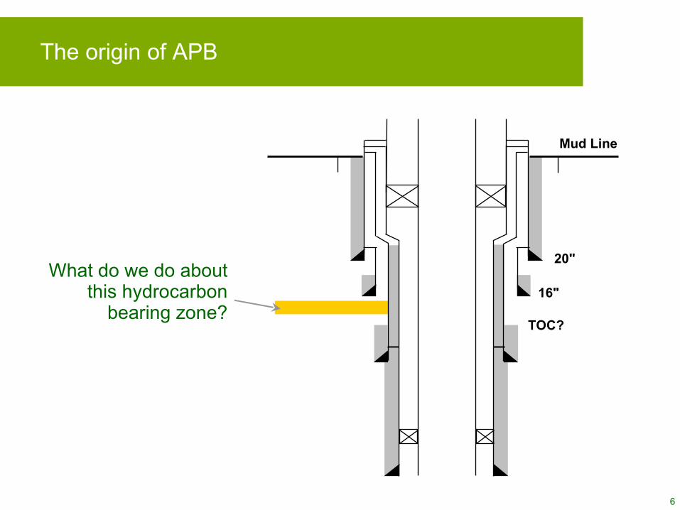
The origin of APB
What do we do about this hydrocarbon
bearing zone?
20"
16"
Mud Line
TOC?

7
APB depends on
• Mechanical and thermal properties of fluid
• Flexibility of the confining boundary
• Temperature increase
Considering the fluid component,
∆−∆=∆ p
CTVV
ffff
1α

8
Mitigating APB
Brute Force
• Thick-walled casing
Fluid Properties
• Foam spacer
• Fluids with low psi/F
• Cement entire annulus
Control the Load
• Vacuum Insulated Tubing (VIT)
• Nitrogen blanket
• Gelled brine
• Connection leak integrity
• Initial annulus pressure
Container Flexibility
• Vent the annulus
− Active path to surface
− Relief mechanism
− Formation fracture/TOC
− Rupture disks
− Grooved casing
• Annulus communication
• Syntactic foam
• Avoid trapped pressures external to annulus

9
Mitigating APB
Fluid Properties
• Foam spacer
• Fluids with low psi/F
• Cement entire annulus

10
Mitigating APB
Container Flexibility
• Vent the annulus
− Active path to surface
− Relief mechanism
− Formation fracture/TOC
− Rupture disks
− Grooved casing
• Annulus communication
• Syntactic foam
• Avoid trapped pressures external to annulus

11
Container Flexibility
• Vent the annulus
− Active path to surface
− Relief mechanism
− Formation fracture/TOC
− Rupture disks
− Grooved casing
• Annulus communication
• Syntactic foam
• Avoid trapped pressures external to annulus
Mitigating APB
12
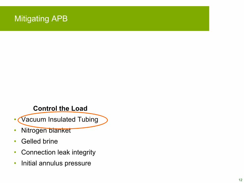
Mitigating APB
Control the Load
• Vacuum Insulated Tubing
• Nitrogen blanket
• Gelled brine
• Connection leak integrity
• Initial annulus pressure
5100
5150
5200
5250
5300
5350
5400
5450
5500
5550
5600
80 90 100 110 120 130 140
Temperature, Deg F
Mea
su
red
Dep
th, f
t.
GelledBrine 2
GelledBrine 1
Connection
Outer Tube
Inner Tube
Vacuum Annulus
Tubing “A” Annulus
Weld
ConnectionConnection
Outer TubeOuter Tube
Inner Tube
Vacuum AnnulusVacuum Annulus
Tubing “A” AnnulusTubing “A” Annulus
Weld

13
5100
5150
5200
5250
5300
5350
5400
5450
5500
5550
5600
80 90 100 110 120 130
Temperature, Deg F
Me
as
ure
d D
ep
th, f
t.
Gelled Brine 1
Gelled Brine 2
Mitigating APB – Vacuum Insulated Tubing (VIT)
Connection
Outer Tube
Inner Tube
Vacuum Annulus
Tubing “A” Annulus
Weld
ConnectionConnection
Outer TubeOuter Tube
Inner Tube
Vacuum AnnulusVacuum Annulus
Tubing “A” AnnulusTubing “A” Annulus
Weld

Designing within wellbore limitations

15
36"
22" (224.0 ppf X-80)
13-5/8" (88.20 ppf HCQ-125)
9-7/8" (62.8 ppf C-110)
7" (38.0 ppf C-110)
28"
11-7/8" (71.80 ppf P-110)
18" (117.0 ppf N-80)
16" (97.0 ppf P-110)
RISK
DE
PT
H
36"
22"(Surface Casing)
13-5/8" (Deep Protective Casing)
9-7/8" (Production casing or tiebacks)
7" (Production Liners)
28"
11-7/8" (Drilling Liners)
18", 16"(Drilling Liners)
Deepwater HPHT wells, maintaining hole size
• Geometric constraints
− Minimum → production tubulars, SSSV
− Maximum → 18-3/4 in. bore
• Possible solutions
− Riserless drilling
− Managed pressure drilling
− Designer muds
− Revisit casing risk profile
− Probability x consequence
− Recovery
− Empirical validation
− Solid expandable liners

16
Maintaining hole size - example
• 8-1/2 in. hole on bottom
• Production tubulars with 18,000+ psi internal yield
• 5-1/2 in. tubing
• 9-3/8 in. upper tieback drift (subsurface safety valve)
• Clearance outside tieback for APB mitigation (syntactic foam)
36”
28”
22” 224.0 ppf (1.000” wall) X-80
18” 117.0 ppf (0.625” wall) N-80
16” 97.0 ppf (0.575” wall) P-110
13-5/8” 88.20 ppf (0.625” wall) HCQ-125
11-7/8” 71.80 ppf (0.582” wall) P-110
9-7/8” 62.80 ppf (0.625 wall) C-110
7” 38.0 ppf (0.540” wall) C-110
36”
28”
22” 224.0 ppf (1.000” wall) X-80
18” 117.0 ppf (0.625” wall) N-80
16” 97.0 ppf (0.575” wall) P-110
13-5/8” 88.20 ppf (0.625” wall) HCQ-125
11-7/8” 71.80 ppf (0.582” wall) P-110
9-7/8” 62.80 ppf (0.625 wall) C-110
7” 38.0 ppf (0.540” wall) C-110
36 in.28 in.
22 in.
18 in.
16 in.
13-5/8 in.
11-7/8 in.
9-7/8 in.
7 in.
36”
28”
22” 224.0 ppf (1.000” wall) X-80
18” 117.0 ppf (0.625” wall) N-80
16” 128.6 ppf (0.781” wall) Q-125
13-3/4” 58.20 ppf (0.400” wall) P-110
12-1/4” 51.60 ppf (0.400” wall) P-110
10-3/4” 108.70 ppf (1.047” wall) C-110
7” 42.70 ppf (0.625” wall) CRA-125
11-3/4” ppf 126.20 (1.109” wall) C-110 x 10-3/4” ppf 108.70 (1.047” wall) C-110
Or SET?
36 in.28 in.
22 in.
18 in.
16 in.
13-3/4 in.
12-1/4 in.
10-3/4 in.
7 in.
Tieback

Extreme landing loads
18
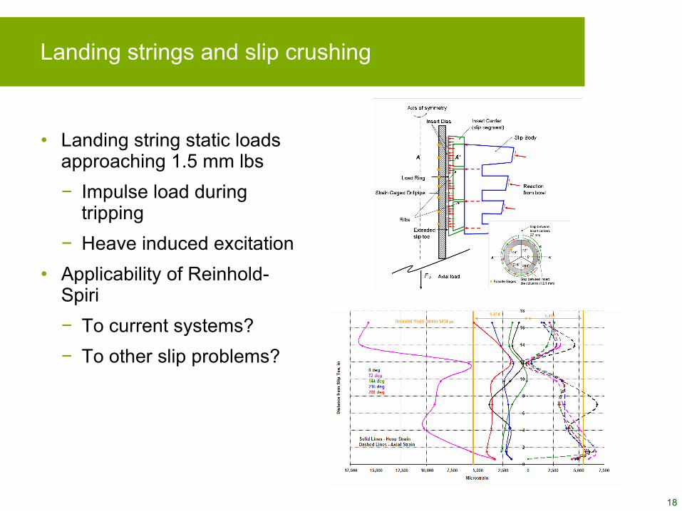
Landing strings and slip crushing
• Landing string static loads approaching 1.5 mm lbs
− Impulse load during tripping
− Heave induced excitation
• Applicability of Reinhold-Spiri
− To current systems?
− To other slip problems?
19
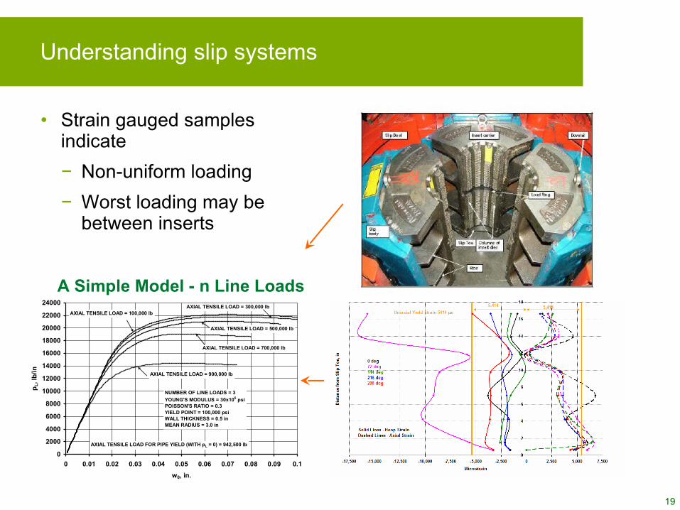
Understanding slip systems
• Strain gauged samples indicate
− Non-uniform loading
− Worst loading may be between inserts
0
2000
4000
6000
8000
10000
12000
14000
16000
18000
20000
22000
24000
0 0.01 0.02 0.03 0.04 0.05 0.06 0.07 0.08 0.09 0.1
w0, in.
pL, l
b/in
NUMBER OF LINE LOADS = 3
YOUNG'S MODULUS = 30x106 psiPOISSON'S RATIO = 0.3YIELD POINT = 100,000 psiWALL THICKNESS = 0.5 inMEAN RADIUS = 3.0 in
AXIAL TENSILE LOAD = 100,000 lbAXIAL TENSILE LOAD = 300,000 lb
AXIAL TENSILE LOAD = 500,000 lb
AXIAL TENSILE LOAD = 700,000 lb
AXIAL TENSILE LOAD FOR PIPE YIELD (WITH pL = 0) = 942,500 lb
AXIAL TENSILE LOAD = 900,000 lb
A Simple Model - n Line Loads

Probabilistic design considerations
21
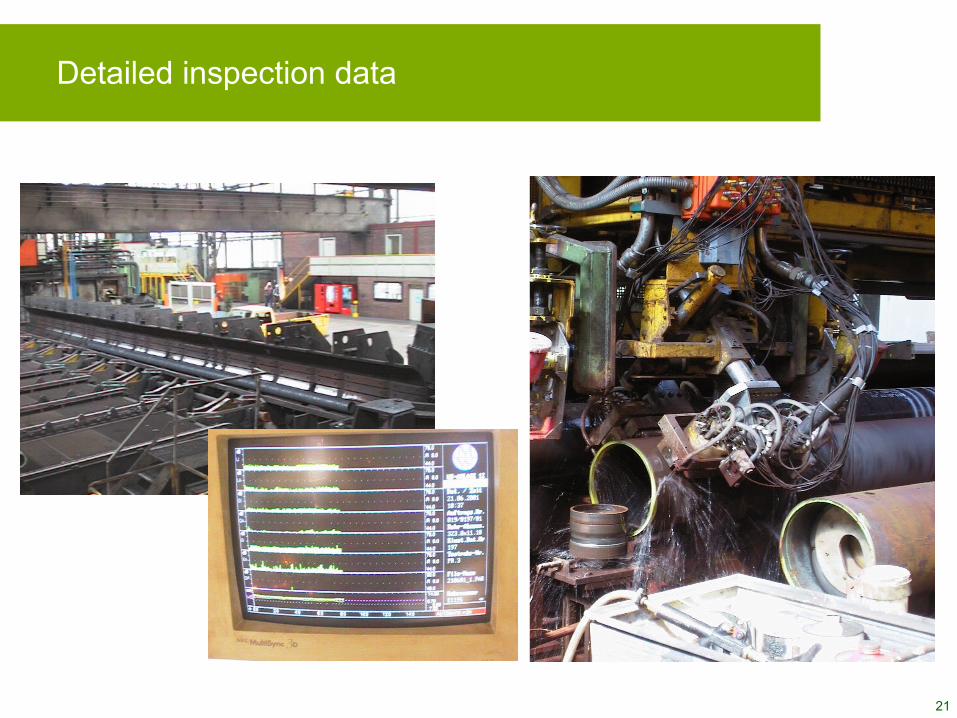
Detailed inspection data

22
Application – calculation of cross-sectional area
23
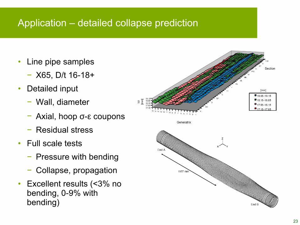
Application – detailed collapse prediction
• Line pipe samples
− X65, D/t 16-18+
• Detailed input
− Wall, diameter
− Axial, hoop σ-ε coupons
− Residual stress
• Full scale tests
− Pressure with bending
− Collapse, propagation
• Excellent results (<3% no bending, 0-9% with bending)

24
Probabilistic advantage using rupture disks
• Disk pressures have tight, controlled tolerances (± 5% on rupture pressure)
• Contrast with 12.5% wall tolerance and 10-30 ksi tensile strength variation for casing body
− Wide uncertainty of casing rupture and collapse pressures
− Cannot count on outer string failing first
7” Production Liner
Consider ifshoe plugs
ABC
Pipe Performance Uncertainty
16"
MIY
P R
atin
g
9-7
/8"
Col
llaps
e R
atin
g
9-7/
8" H
igh
Col
laps
e R
atin
g
7,500 10,000 12,500 15,000 17,500
Pressure (psi)
16" Barlow
16" Rupture
9-7/8" API Collapse
9-7/8" Tamano Collapse
Pipe Performance Uncertainty
16"
MIY
P R
atin
g
9-7
/8"
Col
llaps
e R
atin
g
9-7/
8" H
igh
Col
laps
e R
atin
g
7,500 10,000 12,500 15,000 17,500
Pressure (psi)
16" Barlow
16" Rupture
9-7/8" API Collapse
9-7/8" Tamano Collapse
Pressure
API API
Actual
Collapse
Burst
DiskF
req
uen
cy

25
ISO 10400 (New API 5C3)
Probabilistic properties (from performance or production data)
Details, derivations, performance property tables
Annexes
Identical to existing formulasCollapse, connections, mass, elongation, etc.
8-17
All newDuctile rupture7
von Mises yield
Axial yield, internal yield pressure as special cases
Triaxial yield6
Introduction, symbols1-5
CommentsSubjectClause
26
Conclusions
• No lack of challenging problems
− Continuing research on annular pressure mitigation
− Rethinking old solutions
• Design stretch via probability
− Increasing support from standards