recessed striping in concrete pavement - … no. cdot-dtd-r-2004-13 final report recessed striping...
TRANSCRIPT

Report No. CDOT-DTD-R-2004-13 Final Report RECESSED STRIPING IN CONCRETE PAVEMENT William (Skip) Outcalt
August 2004 COLORADO DEPARTMENT OF TRANSPORTATION RESEARCH BRANCH

The contents of this report reflect the views of the
authors, who are responsible for the facts and
accuracy of the data presented herein. The contents
do not necessarily reflect the official views of the
Colorado Department of Transportation or the
Federal Highway Administration. This report does
not constitute a standard, specification, or regulation.
i

Technical Report Documentation Page 1. Report No. CDOT-DTD-R-2004-13
2. Government Accession No.
3. Recipient's Catalog No. 5. Report Date August 2004
4. Title and Subtitle RECESSED STRIPING IN CONCRETE PAVEMENT
6. Performing Organization Code
7. Author(s) William (Skip) Outcalt
8. Performing Organization Report No. CDOT-DTD-R-2004-13
10. Work Unit No. (TRAIS)
9. Performing Organization Name and Address Colorado Department of Transportation - Research 4201 E. Arkansas Ave. Denver, CO 80222
11. Contract or Grant No. 24.00 13. Type of Report and Period Covered Final Report
12. Sponsoring Agency Name and Address Colorado Department of Transportation - Research 4201 E. Arkansas Ave. Denver, CO 80222
14. Sponsoring Agency Code
15. Supplementary Notes Prepared in cooperation with the US Department of Transportation, Federal Highway Administration
16. Abstract: The durability of markings on concrete pavement has always been a problem. Recently, recesses have been ground into the pavement to allow the markings to sit below the surface of the concrete in hopes that this would reduce the wear on the marking material. However, this method is time-consuming and expensive. In 1999 – 2000 on project NH 0342-034, Castle Rock Construction modified the screed bar on a paver to form grooves for both shoulder stripes and the skip stripe on a 4-lane divided highway – US 34 east of Kersey from about mp 122 to 124 both east and westbound. The contractor welded pieces of 1/4 inch-thick steel to the bottom of the paver screed to form the grooves as the concrete was placed. The grooves for the shoulder stripes are 4.5 inches wide; the groove for the skip stripe is 8 inches wide. This study evaluated the condition of the thermoplastic and pavement marking tape stripes through several winters to see if the grooves provided significant protection for the stripes. Placing lane markings in shallow grooves in the pavement results in considerably longer marking life, making the highway safer for drivers. Implementation: Retroreflectance measurements showed that stripes recessed below the surface of the pavement in grooves remained useful over the full three-year evaluation period. Forming grooves in plastic concrete as the pavement was placed was essentially cost-free as it required only minimal changes to the paving equipment. 17. Keywords: grooves, stripes, pavement marking durability, retroreflectance, retrometers, tapes, thermoplastics, epoxy paint
18. Distribution Statement No restrictions. This document is available to the public through the National Technical Information Service, Springfield, VA 22161
19. Security Classif. (of this report) Unclassified
20. Security Classif. (of this page) Unclassified
21. No. of Pages 14
22. Price
Form DOT F 1700.7 (8-72) Reproduction of completed page authorized
ii

RECESSED STRIPING IN CONCRETE PAVEMENT
by
William (Skip) Outcalt, E/PS Tech II
Report No. CDOT-DTD-R-2004-13
Sponsored by Colorado Department of Transportation
In Cooperation with the U. S. Department of Transportation Federal Highway Administration
August 2004
Colorado Department of Transportation 4201 E. Arkansas Avenue
Denver, CO 80222 (303) 757-9506
iii

ACKNOWLEDGEMENTS
Special thanks are hereby expressed to the study panel members: Richard Gabel, CDOT R4
Traffic, Larry Haas, CDOT R4 Traffic, and Mike Wells, CDOT R4 Engineering.
Thanks to Steve Johnson, CDOT Project Development, and David Weld, CDOT Research, for
help in data collection and analysis.
iv

EXECUTIVE SUMMARY
The durability of markings on concrete pavement has always been a problem. In 1999 Castle
Rock Construction modified the paver in use on CDOT project NH 0342-034, US 34 east of
Kersey, to form grooves for the lane striping as the concrete pavement was placed. By welding
three pieces of 1/4 inch-thick steel to the screed bar on the paver, the contractor was able to form
three continuous grooves – one for each shoulder stripe and one for the skip stripe as the
concrete was placed. The grooves for both shoulder stripes were 4.5 inches wide; the skip stripe
groove was 8 inches wide. The lane marking materials were 3MTM StamarkTM traffic marking
tape in the eastbound lanes and thermoplastic traffic markings in the westbound lanes. The areas
where the shoulder stripes were outside the grooves – acceleration lanes and deceleration lanes –
were marked with Colorado standard epoxy paint with glass beads.
Placing the lane marking stripes in the grooves formed in the surface of the concrete protected
the marking material from damage by snowplows and traffic, and it remained in remarkably
good condition for the duration of the study. High retroreflectivity numbers on the three-year-
old tape, 417 to 514 average for the white and 287 for the yellow, could justify the expense of
installing marking tape rather than using epoxy paint.
IMPLEMENTATION STATEMENT
The groove recesses provide significant protection for and lengthen the life of lane markings. It
is recommended that the modification to the concrete paving machines be adopted as a standard
for use on rural concrete pavement. The placement of striping in grooved pavement is especially
cost-effective on highways where the number of intersections and driveways is low. The only
cost for implementation is the cost of welding three pieces of 1/4-inch-thick steel to the screed
bar on the paving machine.
v

TABLE OF CONTENTS
Background..................................................................................................................................... 1
Construction.................................................................................................................................... 1
Evaluation ....................................................................................................................................... 3
Conclusions and Recommendations ............................................................................................... 6
vi

LIST OF FIGURES
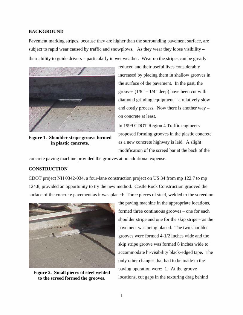
Figure 1. Shoulder stripe groove formed in plastic concrete……………………………………1
Figure 2. Small pieces of steel welded to the screed formed the grooves………………………1
Figure 3. Gaps were cut in the drag to keep the groove smooth………………………………..2
Figure 4. At accel/decel lanes the stripes were placed outside the grooves…………………….2
Figure 5. The Delta LTL2000 measures retroreflectance in any light condition……………….3
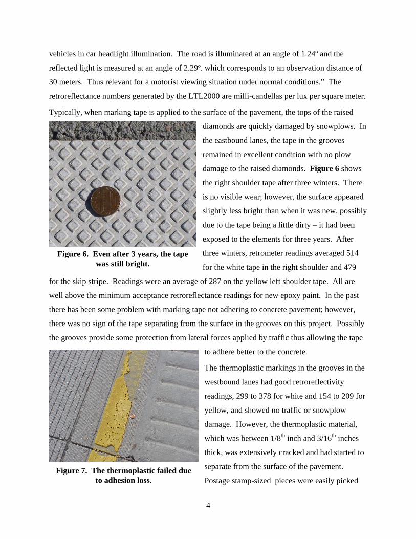
Figure 6. Even after 3 years, the tape was still bright…………………………………………..4
Figure 7. The thermoplastic failed due to adhesion loss…………………………………….….4
Figure 8. Epoxy paint in a groove in perfect condition next to damaged paint on the surface…5
LIST OF TABLES
Table 1. Marking materials cost – 2000..………………………………………………………3
Table 2. Retroreflectometer readings…………………………………………………………..7
vii
BACKGROUND
Pavement marking stripes, because they are higher than the surrounding pavement surface, are
subject to rapid wear caused by traffic and snowplows. As they wear they loose visibility –
their ability to guide drivers – particularly in wet weather. Wear on the stripes can be greatly
reduced and their useful lives considerably
increased by placing them in shallow grooves in
the surface of the pavement. In the past, the
grooves (1/8” – 1/4” deep) have been cut with
diamond grinding equipment – a relatively slow
and costly process. Now there is another way –
on concrete at least.
In 1999 CDOT Region 4 Traffic engineers
proposed forming grooves in the plastic concrete
as a new concrete highway is laid. A slight
modification of the screed bar at the back of the
concrete paving machine provided the grooves at no additional expense.
Figure 1. Shoulder stripe groove formed in plastic concrete.
CONSTRUCTION
CDOT project NH 0342-034, a four-lane construction project on US 34 from mp 122.7 to mp
124.8, provided an opportunity to try the new method. Castle Rock Construction grooved the
surface of the concrete pavement as it was placed: Three pieces of steel, welded to the screed on
the paving machine in the appropriate locations,
formed three continuous grooves – one for each
shoulder stripe and one for the skip stripe – as the
pavement was being placed. The two shoulder
grooves were formed 4-1/2 inches wide and the
skip stripe groove was formed 8 inches wide to
accommodate hi-visibility black-edged tape. The
only other changes that had to be made in the
paving operation were: 1. At the groove
locations, cut gaps in the texturing drag behind Figure 2. Small pieces of steel welded
to the screed formed the grooves.
1

the paver so the drag didn’t round the edges of the grooves. 2. At the grooves, remove the tines
from the tining machine so the bottoms of the grooves would provide a smooth surface for paint
and tape.
When an extra lane is added for a short distance
to serve as an accel/decel lane at an intersection,
the shoulder stripe curves outward to a new
position nearer the outside edge of the pavement.
Since the positions of all of the grooves are
permanently set at a fixed distance from the edge
of the pavement by their welded locations on the
screed, there is no way to adjust the position of
the shoulder stripe groove to allow for the extra
lane. At these locations, whether they are on the left or right shoulder, the groove continues at its
fixed location relative to the edge of the concrete. The painted stripe leaves the groove at the
beginning of the new lane and is painted on the surface of the concrete for the length of the
additional lane. The shoulder stripe then bends back toward the center of the concrete at the end
of the acceleration lane and rejoins the shoulder stripe groove when the lane ends.
Figure 3. Gaps were cut in the drag to keep the groove smooth.
Pavement marking tape and thermoplastic marking material were selected for use in evaluating
the effectiveness of the grooves on the project
since they are both thick and susceptible to
damage by snowplows.
3M Stamarktm tape was used for both shoulder
stripes and the skip stripe in the eastbound lanes.
All three stripes in the westbound lanes were
marked with thermoplastic. Both the tape and
the thermoplastic stripes were stopped at the
beginning of the accel/decel lanes and the curved
shoulder stripes were marked with epoxy paint.
Neither tape nor thermoplastic was used outside the grooves on this project.
Figure 4. At accel/decel lanes the es were placed outside the groovstrip es.
Both the thermoplastic and the marking tape cost more than epoxy paint (significantly more in
the case of the marking tape). However, data below indicates that by placing the stripes in
2

grooves, their much higher retroreflectance over a longer useful lifetime compared to epoxy may
justify the use of the more expensive material. Costs at the time this project was constructed are
shown in Table 1 below for the three types of striping materials used for this evaluation.
Table 1. Marking materials cost – 2000.
Epoxy $1.53/sq. ft.
Thermoplastic $2.05/ sq. ft. 1.3 times Epoxy cost
Tape 4” yellow $8.25/ sq. ft. 5.4 times Epoxy cost
Tape 4” white $8.00/ sq. ft. 5.2 times Epoxy cost
Tape 7” white/black border $9.00/ sq. ft. 5.9 times Epoxy cost
The project was constructed over two summers from 1999 to 2000. The westbound lanes were
completed late in the fall of 1999 and carried two-way traffic over the winter with epoxy
striping. The next fall, after construction was completed, the grooves were thoroughly
sandblasted to remove all remnants of curing compound or cement slurry in the eastbound lanes
and the interim epoxy paint in the westbound lanes and the tape and thermoplastic markings
were installed.
EVALUATION
Both types of pavement markings went through
several winters with no noticeable wear from
traffic or snowplows. Retroreflectance
measurements were taken using a Delta LTL2000
Retrometer. This description is on the first page
of the Delta Retrometer manual: “The LTL2000
Retrometer is a portable field instrument, i
for measuring the retroreflection properties
road markings in car headlight illumination, t
value R1 (coefficient of retro reflected luminanc
is used. R1 is a measure of the lightness of the road marking as seen by drivers of motorized
ntended
of
he
e)
Figure 5. The Delta LTL2000 measures retroreflectance in any light
condition.
3
vehicles in car headlight illumination. The road is illuminated at an angle of 1.24º and the
reflected light is measured at an angle of 2.29º. which corresponds to an observation dista
30 meters. Thus relevant for a motorist viewing situation under normal conditions.” The
retroreflectance numbers generated by the LTL2000 are milli-candellas per lux per square meter.
surface of the pave
nce of
Typically, when marking tape is applied to the ment, the tops of the raised
In
ws
re
fter
ossibly
in the
es
diamonds are quickly damaged by snowplows.
the eastbound lanes, the tape in the grooves
remained in excellent condition with no plow
damage to the raised diamonds. Figure 6 sho
the right shoulder tape after three winters. The
is no visible wear; however, the surface appeared
slightly less bright than when it was new, possibly
due to the tape being a little dirty – it had been
exposed to the elements for three years. A
three winters, retrometer readings averaged 514
for the white tape in the right shoulder and 479
for the skip stripe. Readings were an average of 287 on the yellow left shoulder tape. All are
well above the minimum acceptance retroreflectance readings for new epoxy paint. In the past
there has been some problem with marking tape not adhering to concrete pavement; however,
there was no sign of the tape separating from the surface in the grooves on this project. P
the grooves provide some protection from lateral forces applied by traffic thus allowing the tape
to adhere better to the concrete.
The thermoplastic markings in the grooves
westbound lanes had good retroreflectivity
Figure 6. Even after 3 years, the tape was still bright.
readings, 299 to 378 for white and 154 to 209 for
yellow, and showed no traffic or snowplow
damage. However, the thermoplastic material,
which was between 1/8th inch and 3/16th inch
thick, was extensively cracked and had started to
separate from the surface of the pavement.
Postage stamp-sized pieces were easily picked Figure 7. The thermoplastic failed due
to adhesion loss.
4

up off the pavement. There were extensive areas of the skip stripe where the wind blast from
passing traffic had removed nearly all of the thermoplastic material.
The areas of turn lanes and accel/decel lanes were striped with epoxy paint, as mentioned
r than
ere
;
ft
oxy paint.
at appear brighter yellow are where the
,
condition. There
previously. Its retroreflectivity, 69 to 98 on white and 64 to 75 on yellow, was much lowe
either the tape or the thermoplastic. There w
areas where the paint had been scraped by plows
however, the retroreflectivity remained about the
same as undamaged areas.
At about mp 123.5 in the eastbound lanes, the le
shoulder stripe is a double yellow of ep
The left stripe in Figure 8 is in a groove; the
right stripe is on the surface of the pavement.
Retroreflectivity readings for the two stripes are
nearly the same – the one in the groove averaged
69.8 for five readings; the one on the surface
averaged 70 for five readings. However, as can be seen in the photo, the paint on the surface of
the pavement has begun to come off of the concrete.
The areas of the surface stripe (the one on the right) th
Figure 8. Epoxy paint in a groove in perfect condition next to damaged
paint on the surface.
stripe was scraped by snowplows. The places where the paint is gone seem to be part of the
scraped areas. However, it is impossible to say whether the snowplows directly caused the
missing paint or simply removed paint that was already loose. Most of the paint that shows
evidence of scraping was still firmly stuck to the concrete. It is not known whether the same
method was used to clean the surface for both stripes before the epoxy was installed; however
the paint and beads in the stripe in the groove were completely undamaged after repeated
plowing operations and showed no signs of loosing adhesion to the concrete.
After three winters all of the tape in the eastbound lanes remained in very good
was only one very small – about six inches long – piece that had been damaged by something
being dragged over the tape and tearing it. As Figure 6 shows, the reflective tape was slightly
dirty; however, the retroreflectance numbers for the three-year-old tape were higher than those
for new epoxy paint.
5

Table 2. Retroreflectometer readings
Tape – Recessed May, 2002 Average September, 2003 Average
Right Shoulder – White 764.8 514.5
Skip Stripe – White 721.6 479.3
Left Shoulder – Yellow 287.8 287.3
Thermoplastic – Recessed
Right Shoulder – White 305.8 replaced 2003
– Skip Stripe – White 358.6 replaced 2003
– Left Shoulder – Yellow 179.2 replaced 2003
Epoxy Paint – Not Recessed
– Right Shoulder – White 101.8 replaced
Epoxy Paint*
Not recessed – Rt. Shoulder – White 83 replaced
Recessed – Lt. Shoulder – Yellow 69.8 replaced
Not recessed– Lt. Shoulder – Yellow 70 replaced
* At the time this report was written in 2004 retroreflectance minimums for new epoxy paint
were 300mcd/lux/m2 for white and 250 mcd/lux/m2/ for yellow.
There was some concern about possible effects on vehicle handling during lane changes across
the skip-stripe groove, but the researchers did not notice anything during the evaluation visits to
the site and heard no mention of complaints by the public. The width and depth of the grooves
used on this project are such that they don’t try to redirect the tires of a vehicle crossing them
during lane changes.
CONCLUSIONS AND RECOMMENDATIONS
The retroreflectivity numbers show that the paint in the grooves definitely retains more of its
retroreflectivity than the same paint applied outside the grooves. Thermoplastic markings were
6

protected from traffic and plow damage but the adhesion problems were severe. Marking tape
remained in nearly new condition in the grooves. Further evaluation will be needed to see if the
added expense of traffic marking tape can be justified. However, the results of this study show
that placing lane markings in shallow grooves in the pavement results in considerably longer
marking life, making the highway safer for drivers. The best part of forming the grooves during
construction is that it is nearly cost-free. It entails a little more hand work at the beginning and
end of each day’s paving but these areas are mainly hand finished already.
The slipformed grooves for recessing pavement stripes as reviewed in this report would be a
cost-effective way to increase the useful life of the stripes on a new concrete pavement. A large
part of the problem with traffic stripes as they age is that the marking materials wear off or
simply loose adhesion to the surface. The fact that the paint in the grooves at the site on US-34
remained firmly adhered to the pavement gave testimony to the effectiveness of the grooves.
Even the thermoplastic that broke up and lost adhesion remained in place longer in the grooves
than it would have if it had been exposed to the direct wear of traffic and snowplows
Formed-in grooves are a good option for concrete projects where the need for turn lanes and
accel/decel lanes is limited. Since the grooves cannot be curved in relation to the pavement, it is
necessary for areas where the pavement widens to be striped outside the grooves. This defeats
the purpose of having the grooved pavement to some extent. However, the fact that these areas
are used by only a portion of the traffic on the highway makes them last longer also. Grooving
the plastic concrete to recess the lane markings would be especially effective for rural interstate
highways and other highways with long stretches of highway uninterrupted by intersections and
driveways.
7