recognition of deictic gestures for wearable computing - citeseer
TRANSCRIPT
Aalborg Universitet
Recognition of Deictic Gestures for Wearable Computing
Moeslund, Thomas B.; Nørgaard, Lau
Published in:Gesture in Human-Computer Interaction and Simulation
Publication date:2006
Document VersionPublisher's PDF, also known as Version of record
Link to publication from Aalborg University
Citation for published version (APA):Moeslund, T. B., & Nørgaard, L. (2006). Recognition of Deictic Gestures for Wearable Computing. In S. Gibet, N.Courty, & J. F. Kamp (Eds.), Gesture in Human-Computer Interaction and Simulation (pp. 112-123). IEEEComputer Society Press. Lecture Notes In Artificial Intelligence No. 3881
General rightsCopyright and moral rights for the publications made accessible in the public portal are retained by the authors and/or other copyright ownersand it is a condition of accessing publications that users recognise and abide by the legal requirements associated with these rights.
? Users may download and print one copy of any publication from the public portal for the purpose of private study or research. ? You may not further distribute the material or use it for any profit-making activity or commercial gain ? You may freely distribute the URL identifying the publication in the public portal ?
Take down policyIf you believe that this document breaches copyright please contact us at [email protected] providing details, and we will remove access tothe work immediately and investigate your claim.
Downloaded from vbn.aau.dk on: November 23, 2021
Recognition of Deictic Gesturesfor Wearable Computing
Thomas B. Moeslund and Lau Nørgaard
Laboratory of Computer Vision and Media Technology,Aalborg University, Denmark
Abstract. In modern society there is an increasing demand to access, record andmanipulate large amounts of information. This has inspired a new approach tothinking about and designing personal computers, where the ultimate goal is toproduce a truly wearable computer. In this work we present a non-invasive hand-gesture recognition system aimed at deictic gestures. Our system is based on thepowerful Sequential Monte Carlo framework which is enhanced with respect toincreased robustness. This is achieved by using ratios in the likelihood functiontogether with two image cues: edges and skin color. The system proves to befast, robust towards noise, and quick to lock on to the object (hand). All of whichis achieved without the use of special lighting or special markers on the hands,hence our system is a non-invasive solution.
1 Introduction
In modern society there is an increasing demand to access, record and manipulate largeamounts of information involved in many aspects of professional and private daily life.This has inspired a new approach to thinking about and designing personal computers,where the ultimate goal is to produce a truly wearable computer. Wearable in the senseof being a natural extension of the body like clothes, shoes or glasses. A brief historicoverview of wearable computing is listed below, see [11] for further details.
1268 Earliest recorded mention of eyeglasses1665 Robert Hooke calls for augmented senses1762 John Harrison invents the pocket watch1907 Aviator Alberto Santos-Dumont commissions the creation of the first wristwatch1960 Heilig patents a head-mounted stereophonic TV display1960 Manfred Clynes coins the word ”Cyborg”1961 Edward O. Thorp and Claude Shannon (MIT) builds the first wearable computer,
which is used to predict roulette wheels1966 Ivan Sutherland creates the first computer-based head-mounted display (HMD)1977 Hewlett-Packard releases the HP 01 algebraic calculator watch1979 Sony introduces the Walkman1981 Steve Mann designs backpack-mounted computer to control photographic equip-
ment
S. Gibet, N. Courty, and J.-F. Kamp (Eds.): GW 2005, LNAI 3881, pp. 112–123, 2006.c© Springer-Verlag Berlin Heidelberg 2006
Recognition of Deictic Gestures for Wearable Computing 113
1985 (Wearable) Device for prediction or card counting in casino games were outlawedin the state of Nevada
1989 Private Eye’s HMD sold by Reflection Technology1991 Doug Platt debuts his 286-based ”Hip-PC”1991 Carnegie Mellon University (CMU) team develops VuMan 1 for viewing and
browsing blueprint data1993 Thad Starner starts constantly wearing his computer, based on Doug Platt’s design1993 Feiner, MacIntyre, and Seligmann develop the KARMA augmented reality system1994 Lamming and Flynn develop ”Forget-Me-Not” system, a continuous personal
recording system1996 Boeing hosts “Wearables Conference” in Seattle1997 CMU, MIT, and Georgia Tech co-host the first IEEE International Symposium on
Wearable Computers1997 First Wearable computer fashion show at MIT
1.1 Related Work
A number of different devices have been developed or adopted to the special userinterface requirements in wearable computing [9]. Depending on the context therequirements differ. However, one common issue in most wearable computing inter-faces is the need for a pointing device, similar to the computer mouse used in standardWIMP interfaces. Without it, precise deictic interaction is either not possible or verycumbersome.
The most common way of achieving this is by the use of a data glove, see e.g., [10].Glove-based methods are by nature intrusive and besides often too expensive and bulkyfor widespread use [13]. Other intrusive devices which have been used to provide de-ictic input are bend sensors [13], ultrasonic devices [4], and accelerometers [13]. Lessintrusive methods are based on head-mounted cameras segmenting the hand(s) in theimage. Compared to some of the more intrusive devices cameras in general producepoor signal-to-noise ratios and therefore either infrared light and cameras, see e.g., [14]and [12], or markers on the hands/fingers, see e.g., [10], are used. For further informa-tion on state-of-the-art see [8].
1.2 The Content of This Paper
The aim of this paper is to develop a head mounted camera-based gesture interfacefor wearable computing that neither requires special lighting (infrared) nor markersattached to the hands/fingers. Our approach is to adopt an advanced tracking framework:the Sequential Monte Carlo (SMC) method [3], which is often used in the computervision research field, see e.g., [5][1][2], and tailor it to the needs originating when thecamera is head mounted.
The paper is structured as follows. In section 2 the gestures are defined and a repre-sentation is derived. In section 3 the tracking framework for the gesture recognition ispresented. In section 4 and section 5 the recognition of the pointing gesture is described.In section 6 the system is tested and in section 7 a conclusion is given.
114 T.B. Moeslund and L. Nørgaard
2 Modeling the Pointing Gesture
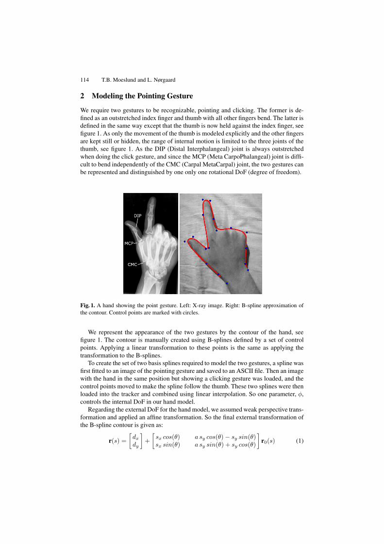
We require two gestures to be recognizable, pointing and clicking. The former is de-fined as an outstretched index finger and thumb with all other fingers bend. The latter isdefined in the same way except that the thumb is now held against the index finger, seefigure 1. As only the movement of the thumb is modeled explicitly and the other fingersare kept still or hidden, the range of internal motion is limited to the three joints of thethumb, see figure 1. As the DIP (Distal Interphalangeal) joint is always outstretchedwhen doing the click gesture, and since the MCP (Meta CarpoPhalangeal) joint is diffi-cult to bend independently of the CMC (Carpal MetaCarpal) joint, the two gestures canbe represented and distinguished by one only one rotational DoF (degree of freedom).
Fig. 1. A hand showing the point gesture. Left: X-ray image. Right: B-spline approximation ofthe contour. Control points are marked with circles.
We represent the appearance of the two gestures by the contour of the hand, seefigure 1. The contour is manually created using B-splines defined by a set of controlpoints. Applying a linear transformation to these points is the same as applying thetransformation to the B-splines.
To create the set of two basis splines required to model the two gestures, a spline wasfirst fitted to an image of the pointing gesture and saved to an ASCII file. Then an imagewith the hand in the same position but showing a clicking gesture was loaded, and thecontrol points moved to make the spline follow the thumb. These two splines were thenloaded into the tracker and combined using linear interpolation. So one parameter, φ,controls the internal DoF in our hand model.
Regarding the external DoF for the hand model, we assumed weak perspective trans-formation and applied an affine transformation. So the final external transformation ofthe B-spline contour is given as:
r(s) =[dx
dy
]+
[sx cos(θ) a sy cos(θ) − sy sin(θ)sx sin(θ) a sy sin(θ) + sy cos(θ)
]r0(s) (1)
Recognition of Deictic Gestures for Wearable Computing 115
where r0(s) is the set of untransformed control points representing the contour of thehand, r(s) is the set of affine transformed control points, dx and dy define the translationin the image plane, sx and sy define the scaling in the image plane, a is the shear, andθ is the rotation in the image plane.
In total we ended up with 7 DoF, one internal and six externals. That is, our state-space is seven-dimensional and one configuration of the hand is defined by the statevector, x, as:
x = (dx, dy, θ, sx, sy, a, φ) (2)
where φ is the angle between the index finger and the thumb.
3 Tracking Framework
Due to the low signal-to-noise ratio mentioned in section 1.1 the hand can not alwaysbe segmented perfectly from the background. Hence, the recognition in a particularframe will not always be unique, or in statically terms, the conditional probability of agesture given the image measurements will in general be multi modal. This calls for aSequential Monte Carlo (SMC) method which can handle such situations [3]. The SMCalgorithm operates as most other tracking frameworks, by using a predict-match-updatestructure.
The SMC is defined in terms of Bayes’ rule and by using the first order Markovassumption. That is, the posterior PDF (probability density function) is proportional tothe observation PDF multiplied by the prior PDF, where the prior PDF is the predictedposterior PDF from time t − 1:
p(xt|ut) ∝ p(ut|xt)p(xt|ut−1) (3)
where x is the state and u contains the image measurements. The predicted posteriorPDF is defined as
p(xt|ut−1) =∫
p(xt|xt−1)p(xt−1|ut−1) dxt−1 (4)
where p(xt|xt−1) is the motion model governing the dynamics of the tracked object,i.e., the prediction, and p(xt−1|ut−1) is the posterior PDF from the previous frame.
This formula is exactly what we are after, as it imposes no constraints on the posteriorPDF, as for example the Kalman filter does. However, even with a coarse resolution forthe different parameters in the state vector (both internal and external DoF), too manycombinations exist and it is not computationally feasible to evaluate the integral in equa-tion 4. Therefore, the SMC algorithm approximates the posterior by only sampling theN most appropriate combinations. In praxis this is done by estimating p(xt|ut) by se-lecting a number, N , of (hopefully) representative states (particles) from p(xt−1|ut−1),predicting these using p(xt|xt−1), and finally giving each particle a weight in accor-dance with the observation PDF, p(ut|xt). For the next time step N new particles aredrawn from the existing set with probabilities proportional to the calculated weights.
This approach will concentrate most particles around the likely hypotheses, but sincethe prediction contains both a deterministic and a stochastic element, some particles willalso spread out randomly making the SMC algorithm able to cope with unpredictedevents.
116 T.B. Moeslund and L. Nørgaard
4 Motion Model
In order to apply the SMC method we need to be able to predict a state vector over time.In this section the motion model, which implements the prediction, is defined.
We assume the individual dimensions in the state space are independent, and can bemodeled by first order auto-regressive (AR) processes:
xt − x = a(xt−1 − x) + bwt ⇔ xt = x + a(xt−1 − x) + bwt (5)
where xt is the value at time t, x is the mean or expected value and wt is a randomvariable with distribution N (0, 1).
The only exception is x and y translation, dx and dy , which are modeled by secondorder AR processes with constant velocity:
xt = xt−1 + (xt−1 − xt−2) + bwt (6)
Consequently there are 12 motion constants to be determined during training. Inaddition, the mean and standard deviation for each dimension are also calculated inorder to determine the a priori distributions used in the initialization of the SMC tracker[9].
The motion model and initialization assume the value and step size along each di-mension of the state space to be normally distributed except dx and dy which are as-sumed uniform. Test justify these assumptions except for the value of the thumb angle,φ, which is not normally distributed [9]. Its histogram has two distinct modes at posi-tions corresponding to the point and click gestures. We handle this by modeling the twomodes by two first order AR processes, as in equation 5, and extend the state vectorwith a variable indicating the current mode (gesture) [6]:
x′ = (x, γ) , γ ∈ {1, 2} (7)
The motion model for the thumb angle is modified to include the modes:
p(φt|φt−1) = p(φt|γt, φt−1)p(γt|φt−1) (8)
where p(φt|γt, φt−1) is one of the two AR processes and p(γt|φt−1) is the probabilityfor a gesture given the angle value in the last frame xt−1. This last probability representsthe knowledge of when the hand changes from one gesture to the other. This model willaccurately follow the movement of the thumb through fast clicks with a reasonableamount of particles. Note that the representation in equation 7 means that the gesturerecognition problem becomes an explicit part of the tracking process, i.e., when thetracking is correct so is the recognized gesture.
5 Likelihood Function
When the contour description of the tracked object has been created and the changes instate from frame to frame can be predicted, comparing the predicted contours with the
Recognition of Deictic Gestures for Wearable Computing 117
actual images is the next step. In the SMC tracker this is represented by the observationPDF described in this section.
This comparison is accomplished by locating edges in the image and examininghow well each predicted contour corresponds to these edges. The edges are located bysearching along a number of normals to the contour. Edges detected on the normalsare referred to as features. The function that measures the correspondence is called alikelihood function and defined via a generative model.
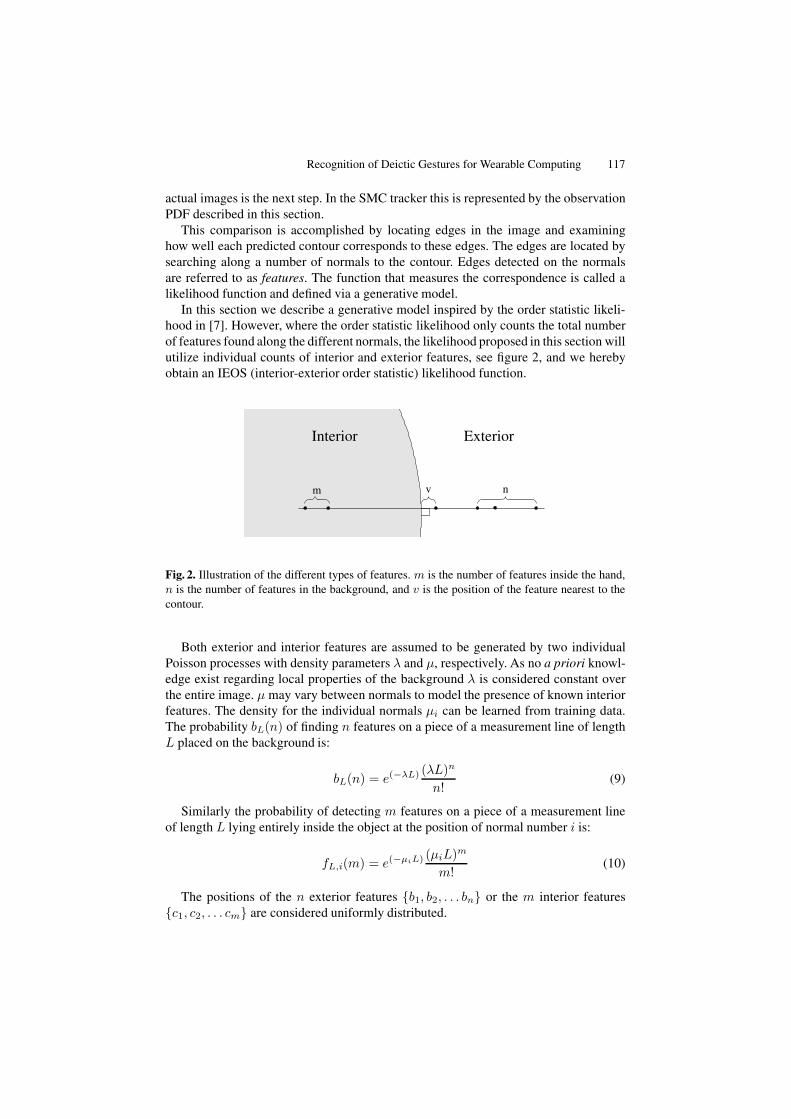
In this section we describe a generative model inspired by the order statistic likeli-hood in [7]. However, where the order statistic likelihood only counts the total numberof features found along the different normals, the likelihood proposed in this section willutilize individual counts of interior and exterior features, see figure 2, and we herebyobtain an IEOS (interior-exterior order statistic) likelihood function.
m n
Interior Exterior
v
Fig. 2. Illustration of the different types of features. m is the number of features inside the hand,n is the number of features in the background, and v is the position of the feature nearest to thecontour.
Both exterior and interior features are assumed to be generated by two individualPoisson processes with density parameters λ and µ, respectively. As no a priori knowl-edge exist regarding local properties of the background λ is considered constant overthe entire image. µ may vary between normals to model the presence of known interiorfeatures. The density for the individual normals µi can be learned from training data.The probability bL(n) of finding n features on a piece of a measurement line of lengthL placed on the background is:
bL(n) = e(−λL) (λL)n
n!(9)
Similarly the probability of detecting m features on a piece of a measurement lineof length L lying entirely inside the object at the position of normal number i is:
fL,i(m) = e(−µiL) (µiL)m
m!(10)
The positions of the n exterior features {b1, b2, . . . bn} or the m interior features{c1, c2, . . . cm} are considered uniformly distributed.

118 T.B. Moeslund and L. Nørgaard
The edge of the hand is assumed to produce a single feature with a position normallydistributed around the center of the normal. There is a fixed probability q0 of this featurenot being detected.
The generative model for the i’th normal with length L can be defined as:
1. Draw a from the truncated Gaussian
G(a) =
{ce(− a2
2σ2 ) , for a ∈ [−L/2; L/2]0 , otherwise
(11)
where a is the distance from the correct edge (originating from the hand) to thecenter of the normal, σ is found during training, and c is set so that the CDF (cu-mulative density function) of G(a) integrates to one.
2. Draw d randomly from {True, False} with probabilities 1 − q0 and q0, respec-tively. d represents whether the edge of the object was detected or not.
3. Draw the number of interior features m randomly from fL/2+a,i(m), and drawtheir positions {c1, c2, . . . cm} from Rect[−L/2, a].
4. Draw the number of exterior features n randomly from bL/2−a(n), and draw theirpositions {b1, b2, . . . bn} from Rect[a, L/2].
5. If d is True:(a) Set v to the position of the most central feature in the set {c1, c2, . . . cm, a, b1,
b2, . . . bn}.If d is False:(a) Set v to the position of the most central feature in the set {c1, c2, . . . cm, b1,
b2, . . . bn}.(b) If v ∈ {c1, c2, . . . cm}: Set m = m -1. Otherwise: Set n = n - 1
6. Report {v, m, n}.
The derivation of the likelihood function is divided into the two cases. One wherethe object edge is detected (d = True) and one where it is not (d = False).
5.1 Edge Not Found (d = False)
As v is the distance to the center of the most central of the m + n + 1 features found,all other features must have a distance greater than or equal to v. The PDF for theposition of the most central feature can not be found directly. It will be established bydetermining the corresponding CDF and then differentiating.
The probability of the distance from the center to a single feature being greater thanor equal to y is1:
P (|v| ≥ y) = (1 − y2/L) (12)
As the positions of the features are assumed independent, the combined probability, thatk features all lie at distances from the center greater than or equal to y, can be calculatedas a product of the k individual probabilities:
P (|v| ≥ y) = (1 − y2/L)k (13)
1 For the following four equations: y ∈ [0; L/2].
Recognition of Deictic Gestures for Wearable Computing 119
The CDF F (y) for the position of the most central of k features from a uniform distri-bution can be found from equation 13:
F (y) = P (|v| ≤ y) = 1 − (1 − y2/L)k (14)
Differentiating 14 with regard to y yields:
d
dyF (y) =
d
dy(1 − (1 − y2/L)k) =
2k
L(1 − y2/L)k−1 (15)
As |v| will always be in the interval [0; L/2], the resulting PDF is:
p(v|d = False) =2k
L(1 − |v|2/L)k−1 (16)
The probability of getting m interior- and n exterior features on the i’th normal, if it iscentered on the border of the object, can be calculated as:
pi(m, n|d = False) = fL/2,i(m)bL/2(n) (17)
The distance from the center of the normal from the most central feature v is notused, as this feature is known to be either an interior or exterior feature and not fromthe edge of the object. However it is not accounted for in m or n, and it will have to beadded to the right category. If the feature at v lies on the interior part of the normal, itshould count as an interior feature or as an exterior feature if it lies on the outside part.That is if v < 0 then set m = m + 1 otherwise set n = n + 1. Adding this to equation17 yields:
pi(m, n|d = False, v) =
{fL/2,i(m + 1)bL/2(n) , if v < 0fL/2,i(m)bL/2(n + 1) , if v ≥ 0
(18)
Equations 16 and 18 can be combined to form the likelihood that the i’th normal,centered on the border of the object, will produce m + n + 1 features where the mostcentral is at position v:
pi(v, m, n|d = False) = pi(m, n|d = False, v)p(v|d = False) =⎧⎪⎪⎪⎨⎪⎪⎪⎩
fL/2,i(m + 1)bL/2(n)2(m+n+1)L ·
(1 − |v|2/L)m+n , if v < 0fL/2,i(m)bL/2(n + 1)2(m+n+1)
L ·(1 − |v|2/L)m+n , if v ≥ 0
(19)
The procedure for the case where the edge is found on the contour (d = True)follows a similar pattern [9] and results in:
pi(v, m, n|d = True) =(
2(m + n)L
(1 − |v|2/L)m+n−1(
1 −∫ |v|
−|v|G(a)da
)
+2(1 − |v|2/L)m+nG(|v|))
fL/2,i(m)bL/2(n) (20)

120 T.B. Moeslund and L. Nørgaard
where v is the distance from the center of the normal to the most central feature. Com-bining equations 19 and 20 we obtain the IEOS likelihood function for the i′th normal:
pieosi(x) = pi(v, m, n) =q0pi(v, m, n|d = False) + (1 − q0)pi(v, m, n|d = True) (21)
Assuming independence of the normals, the likelihood of the entire contour corre-sponding to the state vector x′ is:
Pieos(x′) =M∏i=1
pieosi(x′) (22)
where M is the total number of normals on the contour investigated for one predictedparticle (state). Equation 22 is too long to be stated in its entirety, and consequentlyseems to be a very costly expression to evaluate. However, this is not the case as mostterms can be reduced to lookup tables [9].
5.2 Creating a Likelihood Ratio
The generative models described in the previous section form the basis for the contourlikelihood functions. They can, however, also be used to derive background likelihoodfunctions, that is, functions expressing the likelihood that a given set of features wasproduced by the background. Based on the generative model for the IEOS likelihoodfunction the background likelihood for a single normal will be:
p0 = bL(f)2(f)L
(1 − |v|2/L)m+n (23)
where f = m + n + 1. The corresponding likelihood for all M normals on the entirecontour is:
Bieos(x′) =M∏i=1
bL(fi)2(fi)
L(1 − |vi|2/L)mi+ni (24)
where fi = mi +ni +1. The likelihood function can now be expressed as a ratio whichis more robust to noise:
Rieos(x′) =Pieos(x′)Bieos(x′)
(25)
5.3 Adding Color Information
In order to improve the likelihood function we learn the hue and saturation values ofhands and model the colors by a Gaussian distribution. The distribution in the back-ground is assumed to be uniform over both hue and saturation. Given these assump-tions we can derive a color based ratio between the likelihood of a contour matchingand the likelihood of the contour being located on a random background [9]. Thiscolor based likelihood ratio is denoted Rcolor(x′) and together with equation 25 itforms the final likelihood function used in this work:
Bieosc(x′) = Rieos(x′)Rcolor(x′) (26)
Recognition of Deictic Gestures for Wearable Computing 121
6 Results
The HW used to test our system was the Sony Glasstron PLM-S700E HMD, a PhilipsToUcam Pro USB mounted on the HMD, and a Windows PC with AMD Athlon 2100+and 512 MB RAM. With this HW we recorded different test sequences each having dif-ferent characteristics among the following: translation and rotation of the hand [slow,moderate, fast, very fast], head movement [none, slow, fast], illumination [indoor, out-door, mixed], and background [uniform wall, wooden table, very cluttered desk].
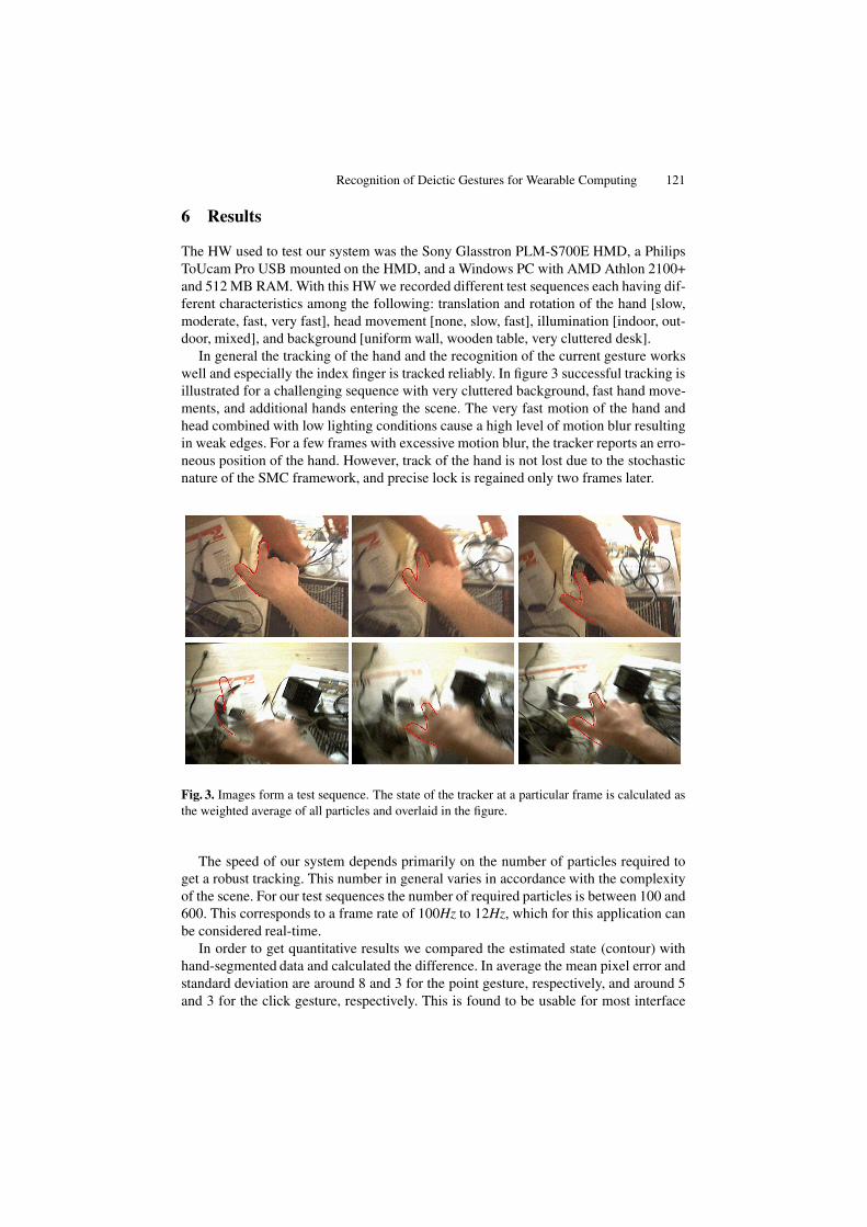
In general the tracking of the hand and the recognition of the current gesture workswell and especially the index finger is tracked reliably. In figure 3 successful tracking isillustrated for a challenging sequence with very cluttered background, fast hand move-ments, and additional hands entering the scene. The very fast motion of the hand andhead combined with low lighting conditions cause a high level of motion blur resultingin weak edges. For a few frames with excessive motion blur, the tracker reports an erro-neous position of the hand. However, track of the hand is not lost due to the stochasticnature of the SMC framework, and precise lock is regained only two frames later.
Fig. 3. Images form a test sequence. The state of the tracker at a particular frame is calculated asthe weighted average of all particles and overlaid in the figure.
The speed of our system depends primarily on the number of particles required toget a robust tracking. This number in general varies in accordance with the complexityof the scene. For our test sequences the number of required particles is between 100 and600. This corresponds to a frame rate of 100Hz to 12Hz, which for this application canbe considered real-time.
In order to get quantitative results we compared the estimated state (contour) withhand-segmented data and calculated the difference. In average the mean pixel error andstandard deviation are around 8 and 3 for the point gesture, respectively, and around 5and 3 for the click gesture, respectively. This is found to be usable for most interface
122 T.B. Moeslund and L. Nørgaard
purposes. To stress this point we made a qualitative test where test persons were askedto control the interaction with the game pieces while playing Tic-Tack-Toe against thecomputer. On a uniform background the game is definitely playable. A few erroneousclicks appeared when playing on a cluttered background, especially in combination withfast hand movements. These clicks were few and could for the most parts be eliminatedby a temporal filter.
Fast head motion was in general not a problem. It was observed, that during interac-tion the hand was kept relatively steady wrt to the head. It seems not plausible to movethe head independently of the hand while pointing at something shown on the HMD.
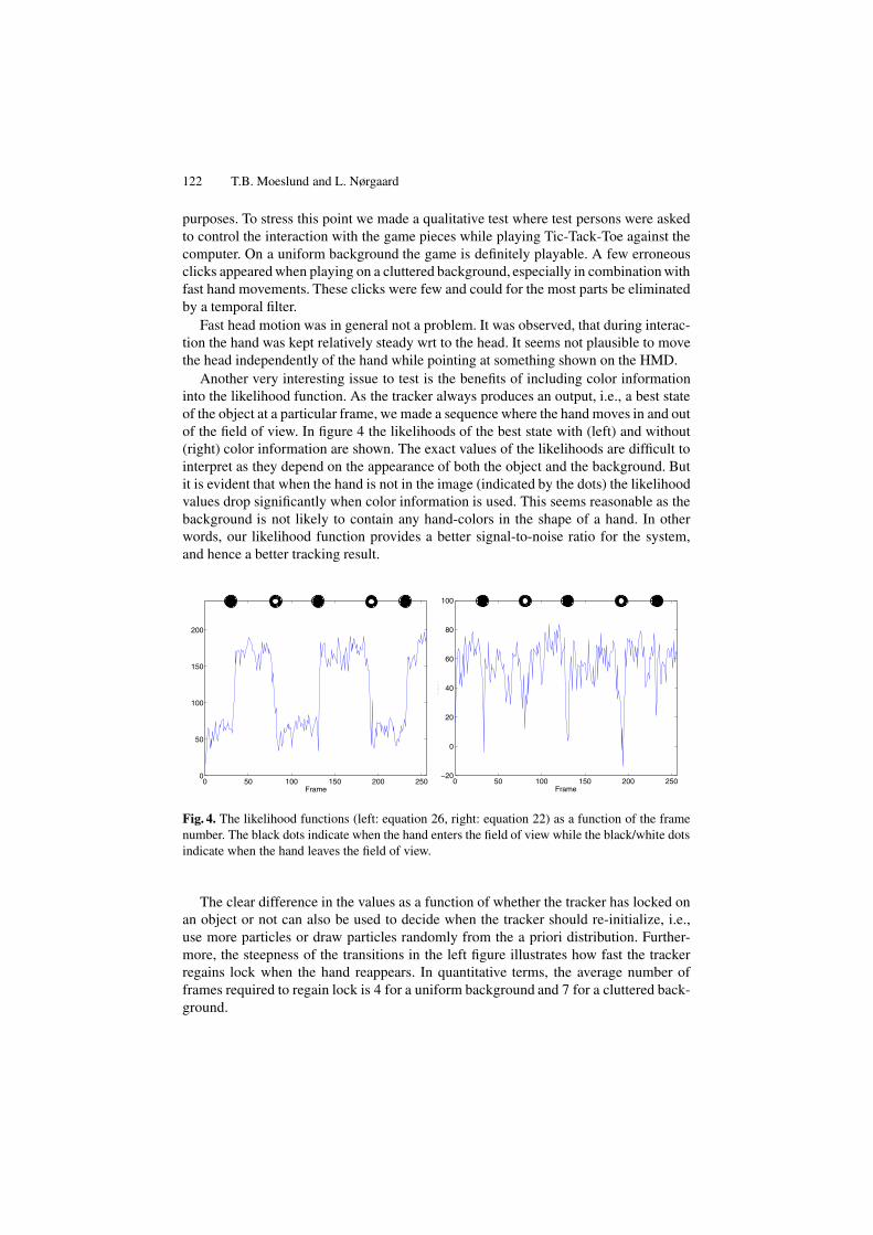
Another very interesting issue to test is the benefits of including color informationinto the likelihood function. As the tracker always produces an output, i.e., a best stateof the object at a particular frame, we made a sequence where the hand moves in and outof the field of view. In figure 4 the likelihoods of the best state with (left) and without(right) color information are shown. The exact values of the likelihoods are difficult tointerpret as they depend on the appearance of both the object and the background. Butit is evident that when the hand is not in the image (indicated by the dots) the likelihoodvalues drop significantly when color information is used. This seems reasonable as thebackground is not likely to contain any hand-colors in the shape of a hand. In otherwords, our likelihood function provides a better signal-to-noise ratio for the system,and hence a better tracking result.
0 50 100 150 200 2500
50
100
150
200
Frame0 50 100 150 200 250
−20
0
20
40
60
80
100
Frame
CLR
Fig. 4. The likelihood functions (left: equation 26, right: equation 22) as a function of the framenumber. The black dots indicate when the hand enters the field of view while the black/white dotsindicate when the hand leaves the field of view.
The clear difference in the values as a function of whether the tracker has locked onan object or not can also be used to decide when the tracker should re-initialize, i.e.,use more particles or draw particles randomly from the a priori distribution. Further-more, the steepness of the transitions in the left figure illustrates how fast the trackerregains lock when the hand reappears. In quantitative terms, the average number offrames required to regain lock is 4 for a uniform background and 7 for a cluttered back-ground.
Recognition of Deictic Gestures for Wearable Computing 123
7 Conclusion
We have presented a non-invasive hand-gesture recognition algorithm for wearablecomputing. The recognized gestures are point and click gestures which are essentialin virtually all interfaces where deictic information is required. Our algorithm is basedon the powerful SMC tracker which can handle multiple hypotheses in the search space.In order to increase the robustness of the tracker we use ratios in the likelihood functionand base it on two image cues which can complement each other: edges and skin color.The likelihood function proves to be very robust towards noise as illustrated in figure 3.Furthermore, as illustrated in figure 4 the algorithm locks on to the object very quicklyand gives a clear indication of whether the hand is present in the frame or not.
The above mentioned characteristics combined with the speed of the algorithm andthe user feedback allow us to conclude that we have developed a powerful deictic inter-face for wearable computing, and that is without requiring special lighting or markerson the hands or fingers, hence our system is a non-invasive solution.
References
1. T.J. Cham and J.M. Rehg. A Multiple Hypothesis Approach to Figure Tracking. In Confer-ence on Computer Vision and Pattern Recognition, Fort Collins, Colorado, 1999.
2. K. Choo and D.J. Fleet. People Tracking Using Hybrid Monte Carlo Filtering. In Interna-tional Conference on Computer Vision, Vancouver, Canada, 2001.
3. A. Doucet, N. Freitas, and N. Gordon, editors. Sequential Monte Carlo Methods in Practice.Springer, 2001.
4. E. Foxlin and M. Harrington. Weartrack: A self-referenced head and hand tracker for wear-able computers and portable vr. In International Symposium on Wearable Computing, At-lanta, Georgia, 2000.
5. M. Isard and A. Blake. CONDENSATION - conditional density propagation for visual track-ing. International Journal on Computer Vision, 29(1), 1998.
6. M. Isard and A. Blake. A mixed-state CONDENSATION tracker with automatic model-switching. In International Conference on Computer Vision, Bombay, India, 1998.
7. J. MacCormick. Stochastic Algorithms for Visual Tracking: Probabilistic Modelling and Sto-chastic Algorithms for Visual Localisation and Tracking. Springer, 2002.
8. T.B. Moeslund and L. Nrgaard. A Brief Overview of Hand Gestures used in Wearable HumanComputer Interfaces. Technical Report CVMT 03-02, AAU, Denmark, 2003.
9. L. Nrgaard. Probabilistic hand tracking for wearable gesture interfaces. Masters thesis, Lab.of Computer Vision and Media Technology, Aalborg University, Denmark, 2003.
10. W. Piekarski and B.H. Thomas. The tinmith system: demonstrating new techniques for mo-bile augmented reality modelling. In Australasian conference on User interfaces, 2002.
11. B. Rhodes. A brief history of wearable computing. www.media.mit.edu/wearables/lizzy/timeline.html.
12. T. Starner, J. Auxier, D. Ashbrook, and M. Gandy. The gesture pendant: A self-illuminating,wearable, infrared computer vision system for home automation control and medical moni-toring. In International Symposium on Wearable Computing, Atlanta, Georgia, 2000.
13. K. Tsukada and M. Yasumura. Ubi-Finger: Gesture Input Device for Mobile Use. In AsiaPacific Conference on Computer Human Interaction, Beijing, China, 2002.
14. N. Ukita, Y. Kono, and M. Kidode. Wearable vision interfaces: towards wearable informationplaying in daily life. In Workshop on Advanced Computing and Communicating Techniquesfor Wearable Information Playing, Nara, Japan, 2002.