recognizing gestures using a multi-touch table and ... · recognizing gestures using a multi-touch...
TRANSCRIPT

Recognizing gestures using a multi-touchtable and Microsoft Kinect
Bachelor of Computer Science — Graduation project
Author:
Daan Smit1
Supervisor:
Robert Belleman2
Signed by:
Robert Belleman
June 14, 2011
[email protected]@uva.nl

Contents
1 Introduction 11.1 Overview of this work . . . . . . . . . . . . . . . . . . . . . . . . . . . . . . . . . . . . . . 1
2 Technology 22.1 Microsoft Surface . . . . . . . . . . . . . . . . . . . . . . . . . . . . . . . . . . . . . . . . . 22.2 Kinect . . . . . . . . . . . . . . . . . . . . . . . . . . . . . . . . . . . . . . . . . . . . . . . 22.3 Combing Surface and Kinect: more than the sum of its parts? . . . . . . . . . . . . . . . . 3
2.3.1 Interference . . . . . . . . . . . . . . . . . . . . . . . . . . . . . . . . . . . . . . . . 32.3.2 Range . . . . . . . . . . . . . . . . . . . . . . . . . . . . . . . . . . . . . . . . . . . 32.3.3 Position requirements . . . . . . . . . . . . . . . . . . . . . . . . . . . . . . . . . . 4
3 Software 63.1 TUIO . . . . . . . . . . . . . . . . . . . . . . . . . . . . . . . . . . . . . . . . . . . . . . . 63.2 libfreenect . . . . . . . . . . . . . . . . . . . . . . . . . . . . . . . . . . . . . . . . . . . . . 6
3.2.1 Validation . . . . . . . . . . . . . . . . . . . . . . . . . . . . . . . . . . . . . . . . . 83.3 OpenCV . . . . . . . . . . . . . . . . . . . . . . . . . . . . . . . . . . . . . . . . . . . . . . 8
4 Kinect capabilities 114.1 Framerate . . . . . . . . . . . . . . . . . . . . . . . . . . . . . . . . . . . . . . . . . . . . . 114.2 X/Y-axis Jitter . . . . . . . . . . . . . . . . . . . . . . . . . . . . . . . . . . . . . . . . . . 114.3 Z-axis Jitter . . . . . . . . . . . . . . . . . . . . . . . . . . . . . . . . . . . . . . . . . . . . 124.4 X/Y-axis Resolution . . . . . . . . . . . . . . . . . . . . . . . . . . . . . . . . . . . . . . . 134.5 Z-axis Resolution . . . . . . . . . . . . . . . . . . . . . . . . . . . . . . . . . . . . . . . . . 144.6 Blind spots . . . . . . . . . . . . . . . . . . . . . . . . . . . . . . . . . . . . . . . . . . . . 14
5 Prototype 195.1 Calibration . . . . . . . . . . . . . . . . . . . . . . . . . . . . . . . . . . . . . . . . . . . . 195.2 Tracking . . . . . . . . . . . . . . . . . . . . . . . . . . . . . . . . . . . . . . . . . . . . . . 20
5.2.1 Identifying on-surface blobs . . . . . . . . . . . . . . . . . . . . . . . . . . . . . . . 205.2.2 Identifying off-surface blobs . . . . . . . . . . . . . . . . . . . . . . . . . . . . . . . 205.2.3 Matching blobs . . . . . . . . . . . . . . . . . . . . . . . . . . . . . . . . . . . . . . 21
5.3 Gesture recognition . . . . . . . . . . . . . . . . . . . . . . . . . . . . . . . . . . . . . . . . 21
6 Conclusions 226.1 Integration . . . . . . . . . . . . . . . . . . . . . . . . . . . . . . . . . . . . . . . . . . . . 226.2 Performance . . . . . . . . . . . . . . . . . . . . . . . . . . . . . . . . . . . . . . . . . . . . 22
I

Abstract
Multi-touch devices allow 2D interaction, this constraints the user to on-surface gestures. To remove thisconstraint 3D data must be made available to multi-touch applications. In this report we attempt todesign a system that can enrich existing multi-touch applications with additional 3D data acquired by aMicrosoft Kinect. We aim to supply this without the need to modify existing multi-touch applications.
In several experiments we measure the limitations of the depth sensor of the Kinect and determinethe distance at which the Kinect is capable of tracking fingers above a multi-touch table. At last wedescribe a prototype application that can collect the available data.
II

CHAPTER 1
Introduction
1.1 Overview of this work
Traditionally interaction with a multi-touch table, like the Microsoft Surface1, is limited to the touchsensitive area on the surface of the table. The interaction stops as soon as contact with the surface islost. This constraints the user to on-surface gestures, which we define as movements performed while incontact with the table’s surface.
Allowing off-surface gestures, defined as hand or finger movement performed above the table’s surface,would greatly increase the possible ways for a user to interact with Surface applications. To facilitatethis an additional sensor is required which is able to provide us with the hand and/or finger positionabove the table’s surface. For this purpose we have selected the Microsoft Kinect2.
There has been some research in hand gesture recognition [1], and with 3D cameras in particular [2][3]. However this has been performed with the restriction of the hand being the closest object to thecamera or with a flat hand facing the camera. Our aim is to produce a gesture recognition system withthe Kinect which is able to function in combination with a Microsoft Surface.
To accurately detect gestures with a Kinect the following should be considered:
1. What are the Kinect’s limitations with regard to range, precision (jitter), accuracy? In other words,what gestures are posible at what distance?
2. Is there an added value in using the Kinect in combination with a Surface.
When these question are answered we can answer our research question: Can we build a system thatallows for both on-surface and off-surface gestures using a Microsoft Surface and a Microsoft Kinect?
1http://www.microsoft.com/2http://www.xbox.com/kinect/
1

CHAPTER 2
Technology
2.1 Microsoft Surface
The Microsoft Surface is a surface computing platform. As such it detects objects on its surface, suchas human fingers performing a gesture. The surface area is acrylic and 53 cm deep and 107 cm wide, ata height of 56 cm[4].
The detection method used in the Surface is called Rear Diffuse Illumination, see figure 2.1a. Thistechnology detects touches by projecting infrared light from below the touch surface. The touch asurfaceis composed of glass with a diffuse material on top that forms both a projection surface and a diffuserthat scatters infrared light that exits the surface. Bright reflections from objects on the surface can bedetected by an infrared camera. The reflections of closeby objects on the touch area are much brighterthan the reflections from the environment.
2.2 Kinect
The Microsoft Kinect, displayed in figure 2.2 is a 3D camera designed for the Microsoft Xbox 360 videogame platform. It follows a reference design by PrimeSense[5], and is equipped with a infrared projectorand camera for the depth image and a color camera for the video image.
The depth image of the Kinect is produced with an infrared laser projector and a monochrome CMOSsensor. The Kinect projects a known infrared pattern of dots on the scene. The distance of objects isdetermined by the reflection of the dots, which is measured by the infrared camera.
DiffusormaterialAcrylicglass
IR light froman illuminator
IR Camera
(a) Rear Diffuse Illumination (b) Microsoft Surface [1 touch area, 2 IRcamera, 3 CPU, 4 IR projector]
Figure 2.1: Detection technology used in the Microsoft Surface.
2

Figure 2.2: A slide from Microsoft’s E3 Conference showing a diagram of the technologies in Kinect.
This method is mostly unaffected by any lighting conditions, but could conflict with any other technol-ogy that makes use of infrared light, and certain materials that reflect infrared light in an unconventionalmanner or not at all.
2.3 Combing Surface and Kinect: more than the sum of its parts?
Using the Microsoft Surface and the Microsoft Kinect together introduces the following points of concern.
� Both devices depend on infrared light to determine the position of objects. Both technologiesassume they are the only source of the infrared light that is reflected back into the camera. Thiscould potentially lead to false assumptions about the position of objects when one device receiveslight that was projected by the other.
� The physical position of the deviced required for gesture recognition could potentially make itimpossible to interact with both simultaneously. The Microsoft Surface only operates within afew milimeters of the touch area, while the Kinect has a range of several meters[5] with possibledegrading precision.
2.3.1 Interference
To determine if the Kinect and the Surface conflict several simple multi-touch applications were run onthe Microsoft Surface with the Kinect at various positions in relation to the Surface’s touch area. Wemanually observed the depth image of the Kinect and the speed at which the applications were able totrack fingers.
When the Kinect is positioned above the Surface and views straight down the speed of the Surfacesignificantly decreases. This was determined manually by making a gesture on the Surface and observingthe speed at which the fingers were tracked. The Surface detected some false touches when there wasactivity between the Kinect and the touch area. The pixels representing the touch area in the Kinect’sdepth image had a value of 2047, which indicates a pixel for which no depth information is available.At high frequency intervals the touch surface flashes spots of various sizes with false depth information.Objects on or above the surface were viewed without difficulty by the Kinect and seemed unaffected bythe interference at the touch area below them.
When the Kinect is positioned at the side of the Microsoft Surface, as seen in figure 2.3, the toucharea catches less of the infrared light projected by the Kinect. The performance of the Surface increasescompared to positioning the Kinect above the Surface. This also causes the high frequency noise observedin the Kinect’s depth image to decrease significantly.
2.3.2 Range
Before we can make any statements about the physical position of the Surface and the Kinect we needto validate the operational range of the device. There is a negative correlation between the distance tothe Kinect and the resolution of the dot pattern projected by the Kinect’s infrared projector. For this
3

Microsoft Surface
Kinect
(a) Viewed from the side.
58◦
96.52 cm
53 cm
107 cm
Kinect
Microsoft
Surface
(b) Viewed from above.
Figure 2.3: The suggested position of the Kinect in relation to the Microsoft Surface.
(a) 60cm, completely visible (b) 59cm, partially visible (c) 58cm, invisible
Figure 2.4: Experiment to determine the Kinect’s minimum detection range: a box in front of the Kinectis moved towards it.
reason we prefer the Kinect as close as possible because objects can be tracked with greater precisionwith a higher resolution. According to the specifications of the PS1080 System on Chip the depth sensorof the Kinect can operate within a range of 0.8 m - 3.5 m.
To validate the minimum range the Kinect was positioned on the floor and a 32.5 cm by 21 cmcardboard box was positioned in front of it. The cardboard box was manually moved towards the Kinectin steps of 1 cm. At 60 cm distance the cardboard box is still completely visible, but changes frompartially visible at 59 cm to completely invisible at 58 cm distance.
The minimum range at which we were able to detect objects was 60 cm. The maximum range wasnot determined because the cardboard box was still clearly visible at 350 cm distance the maximumrange was not determined, which should be more than sufficient.
2.3.3 Position requirements
For the Kinect to operate properly the distance between the Kinect and the closest object on the Surfaceneeds to be at least 60 cm. Because the surface is 53 cm deep the Kinect needs to be able to detectgestures at a distance of at least 133 cm.
Because we know that the Surface is 107 cm wide, and that the Kinect has a horizontal view angleof 58◦[5] we can derive the minimum distance between the Kinect and the Surface in order to observethe complete table. See figure 2.3b.
4

tan(1
2viewangle) =
12surfacewidth
distance(2.1)
distance =53.5
tan(29)(2.2)
= 96.5 (2.3)
If the table has to stand at a distance of 96.5 cm the Kinect needs to be able to detect gestures at adistance of at least 96.5 + 53 = 149.5 cm in order to allow gestures at the far side of the Surface. Theserequirements override the requirements derived from the minimal operation distance as these impose alower limit.
5

CHAPTER 3
Software
We attempt to design a system which is capable of enriching existing multi-touch applications with datafrom the Kinect without the need to modify these applications. The design is outlined in figure 3.1. Inthis section we will discuss the libraries and methods of communication.
3.1 TUIO
Existing multi-touch application use the TUIO protocol1 to receive touch data. Applications can requestthe data from a TUIO server which, in turn, receives the data from a multi-touch device.
The protocol is capable of sending both 2D and 3D data, which allows us to fill in additional datawithout disturbing existing applications that use 2D data exclusively. The 2D data in the TUIO packagesis available without any change if additional data is added. The difference between 2D touch data and3D touch data in a TUIO package is displayed in the table below.
TUIO property 2D surface possible addition 3D surfacePosition x, y z x, y, zAngle a b, c a, b, cMovement vector X,Y Z X, Y, ZRotation vector A B,C A,B,CMotion acceleration m m′ m′′
Rotation acceleration r r′ r′′
We aim to add the data the Kinect can provide by running an additional TUIO server, which replacesthe original TUIO server for applications. An overview is displayed in figure 3.1. The additional serverreceives all packages from the original server and includes any additional data available.
To prevent disruption of existing applications the original TUIO packages will be forwarded immedi-ately when there is no additional data available. When 3D data is available it will only be included in thenext original package that arrives. Copying the additional data into subsequent packages until updateddata is available would make it impossible for applications to determine the age of the additional data.The TUIO protocol lacks support to include such data for all and individual properties.
3.2 libfreenect
To interface with the Kinect we use the python wrapper of the open source library libfreenect2. Thereare two methods of communication offered by libfreenect:
1http://www.tuio.org/2http://openkinect.org
6

Prototype2D touch data
TUIO
Application
Microsoft Kinect
TUIO
TUIO
libfreenect
OpenCV
old situation
new situation
Figure 3.1: The software components
7

SynchronizedThe program calls the functions sync get depth and sync get video to retrieve a depth frame ora video frame respectively.
UnsynchronizedThe program registers a callback function for the depth and/or video images, which are called bylibfreenect when new frames are available.
The synchronized communication is used because it allows to collect multiple frames more easily.Each frame is an 640 by 480 unsigned 16-bit integer numpy3 array. The 5 most significant bits of
each pixel in a frame are always 0, which makes a depth value 11 bits. A depth value of 2047 indicatesan error pixel: a pixel for which no depth data is available. This is either caused by the material of theobject or by a shadow.
The OpenKinect wiki lists an equation4 that shows the correlation between depth values and meters.The equation is shown below, where depth is the depth value from the Kinect and distance is the distancein meters.
distance = 0.1236 ∗ tan(depth/2842.5 + 1.1863) (3.1)
3.2.1 Validation
To validate equation 3.1 we compare the results of our own measurements to the equation. In figure 3.3equation 3.1 is plotted with error bars representing mean ± 4 · stddev where mean is the mean of 5manual measurements and stddev is the standard deviation of those measurements.
The measurements were taken by placing the Kinect on the floor and a lego baseplate in front of theKinect. On the baseplate were 9 lego columns as seen in figure 3.2. The top of the columns was coveredwith masking tape (tesa) to prevent blind spots (discussed in section 4.6). The baseplate was positionvertically perpendicular to the depth axis of the Kinect’s view. In total 13 measurements were done, bymoving the baseplate backwards with steps of 10 cm. Starting with the baseplate at 70 cm from the baseof the Kinect,and the last measurement at 200 cm from the base of the Kinect. Each step the depth ofthe 9 columns was recorded.
The height of each columns can be calculated with the dimensions of a lego brick5. The depth in cmof each columns can then be calculated with the known distance of the baseplate. The columns heightsare displayed in the table below.
columnset height (lego bricks) height (cm)top 3 3.05middle 6 5.93bottom 9 8.81
Based on equation 3.1, which lacks input for pixel coordinates, we assume that the depth value isunnaffected by any lens distortion. By this notion we only considered the values measured on the centercolumn to validate the equation, the values measured on the other columns are ignored.
What can be observed is that equation 3.1 lies within a distance of 3 times the standard deviationfrom the mean. When considering the possible measurement errors during the experiment equation 3.1can be considered accurate.
3.3 OpenCV
When processing the depth image of the Kinect we use the OpenCV function findContours to identifythe blobs in the processed depth image. findCountours uses the method described in [6] to identifycontours in an image. We use this to determine the position of the objects we track.
3http://numpy.scipy.org/4http://openkinect.org/wiki/Imaging_Information5http://www.dimensionsguide.com/dimensions-of-a-standard-lego-brick/
8

3.05 cm
5.93 cm
8.81 cm3.18 cm
3.18 cm
Y-axis X-axis
Z-axis
Figure 3.2: The dimensions and alignment of the large lego columns.
OpenCV is also used to display any images on screen. For this we employ the functions ShowImage incombination with NamedWindow. According to the specifications[5], the Kinect operates within a rangeof 0.8 - 3.5 m. According to equation 4.8 the depth value corresponding to 3.5 m is 993. For outputand debug purposes a depth value can be easily converted to a monochrome OpenCV image by a rightbitshift of 2, which leaves an 8-bit gray value.
9

70 80 90 100 110 120 130 140 150 160 170 180 190 200Distance from the Kinect (cm)
550
600
650
700
750
800
850
900
950
Dis
tan
cere
por
ted
by
the
Kin
ect
(dep
thva
lue)
Accuracy of the depth2meter formula
Figure 3.3: Validation of equation 3.1. The solid line represents equation 3.1. The errorbars show themean and standard deviation of 5 measurements at 13 positions, at 70 - 200 cm from the base of theKinect.
10

CHAPTER 4
Kinect capabilities
4.1 Framerate
According to the specification of the PrimeSense PS1080 System on Chip[5] the Kinect should be ableto deliver 60 frames per second. To validate this we attempt to retrieve as many frames as possible for10 seconds. The results of the experiment are shown in the table below.
number of frames retrieved frames per secondduring 10 seconds
depth image 300 30video image 300 30
both 600 60
The results verify the specifications. The Kinect can deliver 60 frames per second, however theindividual video and depth cameras can deliver no more than 30 frames per second each.
The minimum required framerate depends on the method of gesture recognition and the complexityof the gestures. Since gesture recognition is not handle by our system it is beyond the scope of thisthesis.
4.2 X/Y-axis Jitter
In this experiment we will try to define how precise the Kinect is able to identify the borders of an object.To accurately determine the position of a small or thin object it is essential to identify where the objectstarts and where it ends. The variation in this position is what we define as X-, and Y-axis jitter.
The jitter on the X-, and Y-axis was measured by tracking the position of the top left pixel of thetop of a lego column in the depth image. A lego baseplate was positioned perpendicular at the Kinect’sview axis, at 80 cm from the base of the Kinect. The column mounted on the baseplate, parallel to theKinect’s view axis, was 8.81 cm high and the top of the column was 3.15 by 3.15 cm. The position ofthe top left pixel was tracked during 1000 frames, captured in 33.342 seconds.
To track the top left pixel of an object it is necessary to determine the pixels composing the object.Thepixels composing the top of the column, Pcolumn, were determined by manually setting threshold valuesthat determines which range of depth values are considered part of the column. In this experiment therange of depth values was set at Dcolumncenter ± 6, where Dcolumncenter is the depth value of the centerof the top of the column at the start of the experiment.
The position of the center of the top of the column was identified manually by clicking at the centerin the depth image. All pixels composing the top of the column can be described by equation 4.1 whereDx,y is the depth value of the pixel at (x, y) in the depth image.
Pcolumn = {x, y : Dcolumncenter − 6 ≤ Dx,y ≤ Dcolumncenter + 6} (4.1)
11

0 200 400 600 800 1000frame number
172
177
180
184x-c
oor
din
ate
(a) The position of the top left pixel on the x-axis.
0 200 400 600 800 1000frame number
269
273
275
277
281
y-c
oor
din
ate
(b) The position of the top left pixel on the y-axis.
Figure 4.1: The position of the top left corner of the top of the lego column during 1000 frames capturedin 33.342 seconds.
The position of the top left corner was determined with equation 4.2 where Dx,y is the depth valueof the pixel at coordinates (x, y) in the depth image, pt is the coordinate of the target pixel, determinedeach frame with equation 4.3, and d is the function that computes the square distance between twopixels.
ptopleft = arg min(x,y)∈Pcolumn
d(Px,y, pt) (4.2)
pt = ( min(x,y)∈Pcolumn
(x), min(x,y)∈Pcolumn
(y)) (4.3)
The coordinates of ptopleft, the top left pixel of the top of the column, during 1000 frames are displayedin figure 4.1. We observe that both the frequency and the amplitude of the jitter is less on the x-axisthan the y-axis. Frequency is defined as the mean number of location changes per second and amplitudeas the number of different locations observed in 1000 frames. Both are displayed in the table below.
axis frequency (Hz) amplitudex 4.89 4y 16.31 5
The frequency and amplitude at other distances are plotted in figure 4.2. We cannot bind anyconclusions to the frequency of the x/y-jitter based on the results of this experiment. The amplitudetells us that all pixels are within a range of 3 pixels of their average location on the x-axis, and within arange of 4 pixel of their average location on the y-axis.
4.3 Z-axis Jitter
The jitter on the Z-axis was measured by positioning a 32.5 cm by 21 cm cardboard box in front of theKinect and measuring the depth at the center pixel of the image (320,240) in 1000 consecutive frames.The center pixel was located on the cardboard box at each measured distance. The measurement wasrepeated every 10 cm, starting at 70 cm from the base of the Kinect and ending at 200 cm. The frequency
12

70 80 90 100 110 120 130 140 150 160 170 180 190 200Distance of the baseplate from the Kinect (cm)
0
5
10
15
20
Fre
qu
ency
(Hz)
(a) Frequency, the mean number of location changes dur-ing one second.
70 80 90 100 110 120 130 140 150 160 170 180 190 200Distance of the baseplate from the Kinect (cm)
0
1
2
3
4
5
6
7
8
Am
plitu
de
(nu
mb
erof
valu
es)
(b) Amplitude, the number of different locations observedin 1000 frames.
Figure 4.2: The frequency and amplitude of x-, and y-axis jitter at 70 - 200 cm distance from the baseof the Kinect.
and amplitude of the z-axis jitter are displayed in figure 4.3. Frequency is defined as the mean numberof depth value changes per second and amplitude as the number of different depth values observed in1000 frames.
A difference of 1 from the average depth value is not sufficient to indicate the presence of an object, asthis change could be caused by jitter on the z-axis. However a difference of 3 from the average observedvalue is sufficient to indicate the presence of an object.
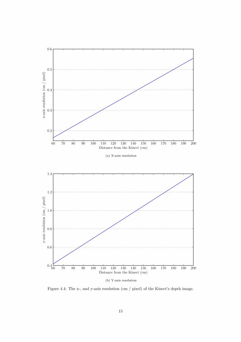
4.4 X/Y-axis Resolution
The resolution on the x-, and y-axis can be derived from the view angle and the number of pixels inthe depth image. The x-axis resolution (cm / pixel) at 60 cm distance is calculated below. H is thehorizontal view angle, D is the distance from the Kinect, and X is the number of pixels on the x-axis inthe depth.
(tan( 12 H) ·D · 2)
X= (4.4)
(tan( 12 58) · 60 · 2)
640= 0.17 (4.5)
The x-, and y-axis resolution for 60 - 200 cm distance is plotted in figure 4.4.
13

70 80 90 100 110 120 130 140 150 160 170 180 190 200Distance from the base of the Kinect (cm)
0
1
2
3
4
5
6
7
8
9
Freq
uenc
y(v
alue
s/
seco
nd)
(a) Frequency, the mean number of value changes persecond.
70 80 90 100 110 120 130 140 150 160 170 180 190 200Distance from the base of the Kinect (cm)
0
1
2
3
4
Am
plit
ude
(num
ber
ofva
lues
)
(b) Amplitude, the number of different values observedin 1000 frames.
Figure 4.3: The frequency and amplitude of z-axis jitter at 70 - 200 cm distance from the base of theKinect.
4.5 Z-axis Resolution
Based on equation 3.1 we assume the depth resolution is independent on the location of a pixel in thedepth image. The resolution on the z-axis (depth) at any distance from the Kinect, can be derived fromequation 3.1. This is shown below for a distance of 70 cm.
distance = 0.1236 · tan(depth/2842.5 + 1.1863) (4.6)
atan(distance/0.1236) = depth/2842.5 + 1.1863 (4.7)
depth = (atan(distance/0.1236)− 1.1863) · 2842.5 (4.8)
D70cm = (atan(0.7/0.1236)− 1.1863) · 2842.5 = 596 (4.9)
Dmin = 0.1236 · tan(594/2842.5 + 1.1863) = 0.6969 (4.10)
Dmax = 0.1236 · tan(598/2842.5 + 1.1863) = 0.7028 (4.11)
1
Dmax −Dmin= 175 (4.12)
At (4.10) and (4.11) we use equation 3.1 to calculate distance in meters at which D70cm±2 at occurs.From (4.12) follows that at 70 cm changes above 175−1 = 5.8 mm can be tracked. The resolution atother distances is displayed figure 4.6.
4.6 Blind spots
The Kinect suffers from blind spots, as seen in figure 4.7. This is related to the material and the angleat which the object is viewed. As human skin does not suffer from this problem it is ignored. In allexperiments the measured objects are covered with masking tape (tesa) as this seems to prevent blindspots.
14
60 70 80 90 100 110 120 130 140 150 160 170 180 190 200Distance from the Kinect (cm)
0.2
0.3
0.4
0.5
0.6
x-a
xis
reso
luti
on(c
m/
pix
el)
(a) X-axis resolution
60 70 80 90 100 110 120 130 140 150 160 170 180 190 200Distance from the Kinect (cm)
0.4
0.6
0.8
1.0
1.2
1.4
y-a
xis
reso
luti
on(c
m/
pix
el)
(b) Y-axis resolution
Figure 4.4: The x-, and y-axis resolution (cm / pixel) of the Kinect’s depth image.
15

3.05 cm
5.93 cm
8.81 cm
1.58 cm
3.18 cm
Y-axis X-axis
Z-axis
Figure 4.5: The dimensions and alignment of the lego columns.
16

60 70 80 90 100 110 120 130 140 150 160 170 180 190 200Distance from the Kinect (cm)
0
50
100
150
200
250
Res
olu
tion
(dep
thva
lue
/m
)
(a) depth value / m
60 70 80 90 100 110 120 130 140 150 160 170 180 190 200Distance from the Kinect (cm)
0.00
0.01
0.02
0.03
0.04
0.05
Res
olu
tion
(m/d
epth
valu
e)
(b) m / depth value
Figure 4.6: The z-axis resolution of the Kinect.
17

Figure 4.7: A blind spot (black) can be seen on the red object (a cardboard box) in the middle of thepicture. There are no objects between the Kinect and the cardboard box in this scene.
18

CHAPTER 5
Prototype
In this section we will discuss a prototype gesture recognition program. The prototype is a partialimplementation of the design discussed in section 3. The calibration and tracking steps, which areimplemented, are necessary in order to include the additional 3D data to the existing TUIO packages.
The prototype first performs a few calibration steps, then tracks the movement of hands on-surfaceand off-surface. The blobs that move off-surface are analyzed for gestures.
5.1 Calibration
The calibration step performs several precalculations, which are required to be performed each time theKinect or the Surface is moved.
The first step of the calibration is building the background model Dbackground. The backgroundmodel is built by taking 30 consecutive frames and taking the average depth value of each pixel. Thisimage is then saved for use in the background subtraction step later.
After the background model is built the touch area of the Surface is selected by the user by clickingon the corners in clockwise order, starting at the topleft corner. The resulting trapezoid is used to createtwo binary masks.
On-surface mask The on-surface mask Ms, shown in figure 5.1a, is an array where everything otherthan the touch area is 0, which allows us to filter out any off-surface activity.
Off-surface mask The off-surface mask Me, shown in figure 5.1b, is an array where everything otherthan the touch area and above is 0. This means that all pixels where something above the toucharea could appear are 1.
To reduce background noise the possible touches above the surface are further thresholded by thefollowing function where Cmax is the maximum depth value of the corners of the trapezoid and Cmin isthe minimum depth value of the corners of the trapezoid. When equation 5.1 is applied to each pixel itfilters out any activity not within the depth range of the Surface. p is the depth value pixel of a pixel.
p =
{p if Cmax < p < Cmin
0 otherwise(5.1)
The last step of the calibration is calculating the touch threshold Tmin and Tmax. The touch thresholdindicates the depth values that could indicate a touch for each pixel in the image. According to theresults from the jitter experiment from section 4.3, Tmin is always at least 2 depth values less than thebackground image created at the start of the calibration procedure, which contains the average depthvalue for each pixel. Tmin is calculated with the following function where depth2meter is equation 3.1and meter2depth is the derived equation 4.8.
19
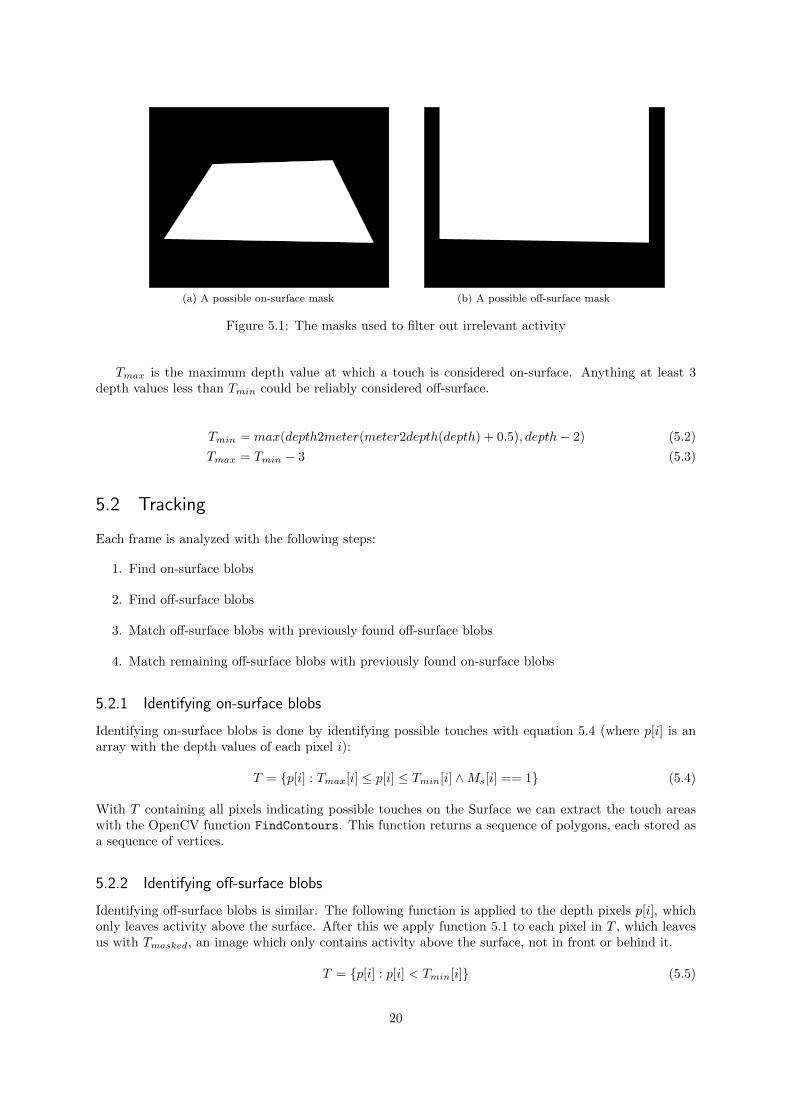
(a) A possible on-surface mask (b) A possible off-surface mask
Figure 5.1: The masks used to filter out irrelevant activity
Tmax is the maximum depth value at which a touch is considered on-surface. Anything at least 3depth values less than Tmin could be reliably considered off-surface.
Tmin = max(depth2meter(meter2depth(depth) + 0.5), depth− 2) (5.2)
Tmax = Tmin − 3 (5.3)
5.2 Tracking
Each frame is analyzed with the following steps:
1. Find on-surface blobs
2. Find off-surface blobs
3. Match off-surface blobs with previously found off-surface blobs
4. Match remaining off-surface blobs with previously found on-surface blobs
5.2.1 Identifying on-surface blobs
Identifying on-surface blobs is done by identifying possible touches with equation 5.4 (where p[i] is anarray with the depth values of each pixel i):
T = {p[i] : Tmax[i] ≤ p[i] ≤ Tmin[i] ∧Ms[i] == 1} (5.4)
With T containing all pixels indicating possible touches on the Surface we can extract the touch areaswith the OpenCV function FindContours. This function returns a sequence of polygons, each stored asa sequence of vertices.
5.2.2 Identifying off-surface blobs
Identifying off-surface blobs is similar. The following function is applied to the depth pixels p[i], whichonly leaves activity above the surface. After this we apply function 5.1 to each pixel in T , which leavesus with Tmasked, an image which only contains activity above the surface, not in front or behind it.
T = {p[i] : p[i] < Tmin[i]} (5.5)
20

unidentifiedblob
unmatched
matchedon-surface
identifiedblob
moving
timed blob
not moving
moving
not moving t < ε
t ≥ ε
Figure 5.2: A flowchart describing the different states of a blob.
5.2.3 Matching blobs
Off-surface blobs are matched with off-surface blobs found in the previous frame by comparing theirposition. Blobs are considered the same when they match d(a, b) < x, where a and b are the positionsof two blobs and d is the function that computes the square distance between two positions. x wasempirically established at 40.
When blobs are matched the position of the old blob is updated instead of creating a new blob.Unmatched off-surface blobs are matched with on-surface blobs. Blobs matched by this method areflagged as identified, as their path from the surface is known. All remaining unmatched blobs from theprevious frame are discarded. All remaining unmatched blobs from this frame are added to the currentlist of blobs.
5.3 Gesture recognition
Within the bounds of the off-surface mask there is no way to differentiate between objects above thesurface at the right or left side of the surface and objects besides the surface at the right or left side. Apossible solution would be to limit gestures to originate from the surface of the multi-touch device. Ob-jects touching the surface are identified by matching them with the presence of more accurate positionaldata from the multi-touch device.
21

CHAPTER 6
Conclusions
6.1 Integration
We have partially succeeded in defining a system that is capable of supplying additional data withoutmodifying existing applications. We have determined the precision and accuracy with which the Kinectcan provide this data on various distances. What we can conclude from the z-axis resolution experimentof section 4.5, as shown in figure 4.6b, is that the Kinect is unable to provide us with precise enoughdata to identify fingers at the distance required, as discussed in section 2.3.3. Assumed is that trackingfingers requires us to track objects with a size of 1 cm. Tracking objects with that size is impossible froma distance of 100 cm and up. The far side of a Microsoft Surface would be at least 149.5 cm removedfrom the Kinect.
6.2 Performance
The performance of the prototype was measured on a machine with the following specifications:
Processor Intel Core 2 Duo E8500 (3.8 GHz)
Memory 4 GB DDR 2 (400 MHz)
Motherboard Asus P5Q Deluxe
The framerate was measured by counting the number of frames that were processed within 1 second.The current framerate was observed for 100 seconds, resulting in 100 framerate measures. The maximum(and average) framerate was 12.
The latency was measured with Python’s timeit module1. The following code was used.
setup_stmt = """
from main import TouchSurface
s = TouchSurface ()
s.update ()
"""
print timeit.repeat(stmt='s.process_frame ()',
setup=setup_stmt , repeat=5, number =100)
The setup statement initializes the Kinect and runs the calibration procedure described in section 5.1.When setup statement is finished processing, the statement s.process frame() is ran 100 times. Thefunction process frame() handles the tracking of blobs as discussed in section 5.2. The whole processis repeated 5 times. The minimum time to process 1 frame is 145 microseconds.
1http://docs.python.org/library/timeit.html
22

Bibliography
[1] S. Malassiotis, N. Aifanti, and M. G. Strintzis. A gesture recognition system using 3d data. Pro-ceedings of the 1st International Symposium on 3D Data Processing Visualization and Transmission,pages 190–193, 2002.
[2] S.E. Ghobadi, O.E. Loepprich, K. Hartmann, and O. Loffeld. Hand segmentation using 2d/3d images.Proceedings of Image and Vision Computing New Zealand 2007, pages 64–69, December 2007.
[3] Seyed Eghbal Ghobadi, Omar Edmond Loepprich, Farid Ahmadov, Jens Bernshausen, Klaus Hart-mann, and Otmar Loffeld. Real time hand based robot control using multimodal images. IAENGInternational Journal of Computer Science, 35(4):500–505, December 2008.
[4] Microsoft surface fact sheet. http://www.microsoft.com/presspass/presskits/surfacecomputing/
docs/MSSurfaceFS.doc, May 2007.
[5] The primesensor reference design 1.08. http://www.primesense.com/files/FMF_2.PDF, 2010.
[6] S. Suzuki and K. Abe. Topological structural analysis of digital binary image by border following.Computer Vision, Graphics, and Image Processing, 30(1):32–46, 1985.
23