recommendation itu-r m.1457-1 - detailed …€¦ · web view · 2003-05-09detailed...
TRANSCRIPT

Rec. ITU-R M.1457-1 1
RECOMMENDATION ITU-R M.1457-1
Detailed specifications of the radio interfaces of International
Mobile Telecommunications-2000 (IMT-2000)*
(2000-2001)
CONTENTS
Page
1 Introduction .................................................................................................................... 2
2 Scope .............................................................................................................................. 3
3 Related Recommendations ............................................................................................. 3
4 Considerations ................................................................................................................ 5
4.1 Radio interfaces for IMT-2000 .......................................................................... 5
4.2 Incorporation of externally developed specification material ............................ 5
4.3 Satellite component interfaces ........................................................................... 6
4.3.1 Radio interfaces ................................................................................... 6
4.3.2 Other interfaces.................................................................................... 8
5 Recommendations (terrestrial component) .................................................................... 9
5.1 IMT-2000 CDMA Direct Spread ....................................................................... 9
5.1.1 Overview of the radio interface ........................................................... 9
5.1.2 Detailed specification of the radio interface ........................................ 25
5.2 IMT-2000 CDMA Multi-Carrier ........................................................................ 55
5.2.1 Overview of the radio interface ........................................................... 55
5.2.2 Detailed specification of the radio interface ........................................ 69
* The recommended detailed specifications of the radio interfaces of IMT-2000 are contained in the core global specifications which form part of this Recommendation by means of references to uniform resource locators (URLs) at the ITU Web site. For those cases where recognized external organizations have converted these core global specifications or parts thereof into their own approved standards, a reference to the corresponding external text is included in this Recommendation by means of URLs at their Web sites. Such references do not give the external texts the status, as stand-alone texts, of ITU Recommendations. Any reference to an external text is accurate at the time of approval of this Recommendation. Since the external text may be revised, users of this Recommendation are advised to contact the source of the external text to determine whether the reference is still current. This Recommendation will be subject to periodic updates that will be coordinated with the appropriate recognized external organizations responsible for the external texts that are referenced.

2 Rec. ITU-R M.1457-1
Page
5.3 IMT-2000 CDMA TDD ..................................................................................... 74
5.3.1 Overview of the radio interface ........................................................... 74
5.3.2 Detailed specification of the radio interface ........................................ 94
5.4 IMT-2000 TDMA Single-Carrier....................................................................... 116
5.4.1 Overview of the radio interface ........................................................... 116
5.4.2 Detailed specifications of the radio interface ...................................... 123
5.5 IMT-2000 FDMA/TDMA .................................................................................. 131
5.5.1 Overview of the radio interface ........................................................... 131
5.5.2 Detailed specification of the radio interface ........................................ 143
6 Recommendations (satellite component) ....................................................................... 145
6.1 Core network interface ....................................................................................... 145
6.2 Satellite/terrestrial terminal interface ................................................................. 146
6.3 Satellite radio interface specifications ............................................................... 146
6.3.1 Satellite radio interface A specifications ............................................. 146
6.3.2 Satellite radio interface B specifications ............................................. 160
6.3.3 Satellite radio interface C specifications ............................................. 181
6.3.4 Satellite radio interface D specifications ............................................. 206
6.3.5 Satellite radio interface E specifications ............................................. 222
6.3.6 Satellite radio interface F specifications .............................................. 233
7 Recommendations on unwanted emission limits ........................................................... 247
7.1 Terrestrial radio interfaces ................................................................................. 247
7.2 Satellite radio interfaces ..................................................................................... 247
1 IntroductionIMT-2000’s are third generation mobile systems which are scheduled to start service around the year 2000 subject to market considerations. They will provide access, by means of one or more radio links, to a wide range of telecommunications services supported by the fixed telecommunication networks (e.g. PSTN/ISDN/Internet protocol (IP)), and to other services which are specific to mobile users.
A range of mobile terminal types is encompassed, linking to terrestrial and/or satellite-based networks, and the terminals may be designed for mobile or fixed use.
Key features of IMT-2000 are:– high degree of commonality of design worldwide;– compatibility of services within IMT-2000 and with the fixed networks;

Rec. ITU-R M.1457-1 3
– high quality;– small terminal for worldwide use;– worldwide roaming capability;– capability for multimedia applications, and a wide range of services and terminals.
IMT-2000 are defined by a set of interdependent Recommendations of which this one is a member.
Recommendation ITU-R M.1455 defines the key characteristics of the IMT-2000 radio interfaces, and represents the results of the evaluation process by the ITU-R on IMT-2000 radio interface proposals submitted to the ITU to a set of defined requirements.
This Recommendation forms the final part of the process of specifying the radio interfaces of IMT-2000, as defined in Recommendation ITU-R M.1225. It identifies the detailed specifications for the IMT-2000 radio interfaces.
This Recommendation has been developed based on consideration of the evaluation results and consensus building, continuing from the IMT-2000 key characteristics defined in Recommendation ITU-R M.1455 and recognizing the need to minimize the number of different radio interfaces and maximize their commonality, while incorporating the best possible performance capabilities in the various IMT-2000 radio operating environments.
2 Scope This Recommendation identifies the IMT-2000 terrestrial and satellite radio interface specifications, based on the key characteristics identified in Recommendation ITU-R M.1455 and output of activities outside ITU.
These radio interfaces support the features and design parameters of IMT-2000, including the capability to ensure worldwide compatibility and international roaming.
3 Related RecommendationsThe existing IMT-2000 Recommendations that are considered to be of importance in the development of this particular Recommendation are as follows:
Recommendation ITU-R M.687: International Mobile Telecommunications-2000 (IMT-2000)
Recommendation ITU-R M.816: Framework for services supported on International Mobile Telecommunications-2000 (IMT-2000)
Recommendation ITU-R M.817: International Mobile Telecommunications-2000 (IMT-2000) – Network architectures
Recommendation ITU-R M.818: Satellite operation within International Mobile Telecommuni-cations-2000 (IMT-2000)
Recommendation ITU-R M.819: International Mobile Telecommunications-2000 (IMT-2000) for developing countries
Recommendation ITU-R M.1034: Requirements for the radio interface(s) for International Mobile Telecommunications-2000 (IMT-2000)
4 Rec. ITU-R M.1457-1
Recommendation ITU-R M.1035: Framework for the radio interface(s) and radio sub-system func-tionality for International Mobile Telecommunications-2000 (IMT-2000)
Recommendation ITU-R M.1036: Spectrum considerations for implementation of International Mobile Telecommunications-2000 (IMT-2000) in the bands 1 885-2 025 MHz and 2 110-2 200 MHz
Recommendation ITU-R M.1167: Framework for the satellite component of International Mobile Telecommunications-2000 (IMT-2000)
Recommendation ITU-R M.1224: Vocabulary of terms for International Mobile Telecommuni-cations-2000 (IMT-2000)
Recommendation ITU-R M.1225: Guidelines for evaluation of radio transmission technologies for IMT-2000
Recommendation ITU-R M.1308: Evolution of land mobile systems towards IMT-2000
Recommendation ITU-R M.1311: Framework for modularity and radio commonality within IMT-2000
Recommendation ITU-R M.1343: Essential technical requirements of mobile earth stations for global non-geostationary mobile-satellite service systems in the bands 1-3 GHz
Recommendation ITU-R M.1455: Key characteristics for the International Mobile Telecommu-nications (IMT-2000) radio interfaces
Recommendation ITU-R M.1480: Essential technical requirements of mobile earth stations of geostationary mobile-satellite systems that are implementing the global mobile personal communications by satellite (GMPCS) – Memorandum of Understanding arrangements in parts of the frequency band 1-3 GHz
Recommendation ITU-R SM.329: Spurious emissions
ITU-T Recommendation Q.1701: Framework of IMT-2000 networks
ITU-T Recommendation Q.1711: Network functional model for IMT-2000
ITU-T Recommendation Q.1721: Information flows for IMT-2000 capability set 1
ITU-T Recommendation Q.1731: Radio-technology independent requirements for IMT-2000 layer 2 radio interface
Handbook on land mobile (including wireless access), Volume 2: Principles and approaches on evolution to IMT-2000/FPLMTS.
Rec. ITU-R M.1457-1 5
4 Considerations
4.1 Radio interfaces for IMT-2000
IMT-2000 consists of both terrestrial component and satellite component radio interfaces. All of the radio interfaces for IMT-2000 both terrestrial and satellite are fully encompassed by this Recommendation. In particular, the terrestrial radio interfaces are fully defined by information supplied within this Recommendation and by information incorporated by reference to external materials. The satellite radio interfaces are fully defined by information supplied with this Recommendation.
Recommendation ITU-R M.1455 lists the key characteristics of all radio interface for the terrestrial component of IMT-2000. The organization of terrestrial radio interfaces within that Recommen-dation continues the philosophy that IMT-2000 should comprise a single terrestrial standard encompassing two high-level groupings: code division multiple access (CDMA), time division multiple access (TDMA), or a combination thereof. The CDMA grouping accommodates frequency division duplex (FDD) direct spread, FDD multi-carrier and time division duplex (TDD). The TDMA grouping accommodates FDD and TDD, single carrier and multi-carrier. These groupings satisfy the needs expressed by the global community.
Recommendation ITU-R M.1455 also lists the key characteristics of six radio interfaces for the satellite component of IMT-2000. As highlighted in that Recommendation, due to the constraints on satellite system design and deployment, several satellite radio interfaces will be required for IMT-2000 (see Recommendation ITU-R M.1167 for further considerations).
A satellite system is severely resource limited (e.g. power and spectrum limited), its radio interfaces are therefore specified primarily based on a whole system optimization process, driven by the market needs and business objectives. It is generally not technically feasible or viable from a business point-of-view to have a radio interface common to satellite and terrestrial IMT-2000 components. Nevertheless, it is desirable to achieve as much commonality as possible with the terrestrial component when designing and developing an IMT-2000 satellite system.
The strong dependency between technical design and business objectives of an IMT-2000 satellite system requires a large scope of flexibility in the satellite radio interface specifications. Future modifications and updates of these specifications may nevertheless be needed in order to adapt to changes in market demands, business objectives, technology developments, and operational needs, as well as to maximize the commonality with terrestrial IMT-2000 systems as appropriate.
The radio interfaces for the terrestrial and satellite components are described in detail in § 5 and 6, respectively.
4.2 Incorporation of externally developed specification material
IMT-2000 is a system with global development activity and the IMT-2000 radio interface specifications identified in this Recommendation have been developed by the ITU in collaboration with the radio interface technology proponent organizations, global partnership projects and regional standards development organizations (SDOs). The ITU has provided the global and overall framework and requirements, and has developed the core global specifications jointly with these organizations. The detailed standardization has been undertaken within the recognized external

6 Rec. ITU-R M.1457-1
organization (see Note 1), which operate in concert with the radio interface technology proponent organizations and global partnership projects. This Recommendation therefore makes extensive use of references to externally developed specifications.NOTE 1 – A "recognized organization" in this context is defined to be a recognized SDO that has legal capacity, a permanent secretariat, a designated representative, and open, fair, and well-documented working methods.
This approach was considered to be the most appropriate solution to enable completion of this Recommendation within the aggressive schedules set by the ITU and by the needs of adminis-trations, operators and manufacturers.
This Recommendation has therefore been constructed to take full advantage of this method of work and to allow the global standardization time-scales to be maintained. The main body of this Recommendation has been developed by the ITU, with references within each radio interface pointing to the location of the more detailed information. The sub-sections containing this detailed information have been developed by the ITU and the recognized external organizations. Such use of referencing has enabled timely completion of the high-level elements of this Recommendation, with change control procedures, transposition (conversion of the core specifications into SDO deliver-ables) and public enquiry procedures being undertaken within the recognized external organization.
The structure of the detailed specifications received from the recognized external organization has generally been adopted unchanged, recognizing the need to minimize duplication of work, and the need to facilitate and support an on-going maintenance and update process.
This general agreement, that the detailed specifications of the radio interface should to a large extent be achieved by reference to the work of recognized external organizations, highlights not only the ITU's significant role as a catalyst in stimulating, coordinating and facilitating the development of advanced telecommunications technologies, but its forward-looking and flexible approach to the development of this and other telecommunications standards for the 21st century.
4.3 Satellite component interfaces
The terrestrial and satellite components are complementary, with the terrestrial component providing coverage over areas of land mass with population density considered to be large enough for economic provision of terrestrially-based systems, and the satellite component providing service elsewhere by a virtually global coverage. The ubiquitous coverage of IMT-2000 can only therefore be realized using a combination of satellite and terrestrial radio interfaces.
To fulfil the scope given in § 2, this Recommendation describes those elements needed for worldwide compatibility of operation noting that international use is inherently ensured through the global coverage of a satellite system. This description includes consideration of all the satellite component interfaces.
Figure 1, which has been developed from Fig. 1 of Recommendation ITU-R M.818, shows the various interfaces in the IMT-2000 satellite component.
4.3.1 Radio interfaces
4.3.1.1 Service link interface
The service link interface is the radio interface between a mobile earth station (MES) (the satellite module of a user terminal (UT)) and a space station.
Rec. ITU-R M.1457-1 7
1457-01
Satellitemodule
Terrestrialmodule
User terminal
Service linkinterface
Inter-satellitelink interface
Feeder linkinterface
Land earth station
Corenetworkinterface
Optional implementation
Space station
FIGURE 1Interfaces in the satellite component of IMT-2000
Satellite/terrestrialterminal interface
4.3.1.2 Feeder link interface
The feeder link interface is the radio interface between space stations and land earth stations (LESs). Feeder links are analogous to the radio interfaces used on back-haul fixed links to carry traffic to/from terrestrial base stations (BS). When designing a satellite system, system specific implementations for feeder links result since:– feeder links can operate in any of a number of frequency bands, which are outside those
bands identified for IMT-2000;– each individual feeder link presents its own issues, some of which are related to satellite
system architecture, while others are related to the frequency band of operation.
The feeder link interface is therefore largely an intra-system specification, and can be viewed as an implementation issue. This has been addressed in Recommendation ITU-R M.1167, which states that "The radio interfaces between the satellites and the LESs (i.e. the feeder links) are not subject to IMT-2000 standardization". The specification of this interface is therefore outside the scope of this Recommendation.
4.3.1.3 Inter-satellite link interface
The inter-satellite link interface is the interface between two space stations, noting that some systems may not implement this interface. The issues discussed above under feeder link interface are also applicable here, and the inter-satellite link interface is therefore largely an intra-system specification, and can be viewed as an implementation issue. The specification of this interface is therefore outside the scope of this Recommendation.

8 Rec. ITU-R M.1457-1
4.3.2 Other interfaces
It is recognized that the core network (CN) and satellite/terrestrial terminal interfaces described below are not radio interfaces. However, it is also recognized that they have a direct impact on the design and specification of satellite radio interfaces and on the worldwide compatibility of operation. Other IMT-2000 Recommendations also make reference to these interfaces.
4.3.2.1 CN interface
The CN interface is the interface between the radio access part of a LES and the CN.
The following describes one possible architecture for the satellite component to interface to the CN, as shown in Fig. 2. This architecture would provide some compatibility with the terrestrial component. In this example, the CN interface for the satellite component is called the Ius. The Ius interface performs similar functions as the Iu interface described in § 5.1 and 5.3, and will be designed to achieve as much commonality as possible with the Iu interface, so as to be compatible with the Iu interface.
The satellite radio access network (SRAN) consists of the LES and the satellite, together with the feeder link and inter-satellite links (if any). The SRAN uses the Ius interface for communicating with the CN and Uus interface for communicating with the UT for satellite service provision. The Uus interface is the satellite service link radio interface which is specified in § 6.3.
Since the satellite component of IMT-2000 is generally global in nature, it is not necessary to provide an interface from the SRAN of one satellite network to the SRAN of another satellite network. Also, the interface between LESs of the same satellite network is an internal implementation issue of the satellite network, thus there is no need for standardization of this interface.
1457-02
CN
SRAN
UT
Uus
Ius
FIGURE 2Example of a satellite network interface architecture
Rec. ITU-R M.1457-1 9
4.3.2.2 Satellite/terrestrial terminal interface
The satellite/terrestrial terminal interface is the interface between the satellite and terrestrial modules within a user terminal. For terminals incorporating both the satellite and terrestrial components of IMT-2000, there is a requirement to identify both how the two components operate together and any interfacing necessary between them.
For example, Recommendation ITU-R M.818 highlights "that a protocol be developed to establish whether a terrestrial or satellite component should be used for a given call". Recommendation ITU-R M.1167 also recognizes that "An IMT-2000 user should not necessarily need to request the terminal to access the satellite or the terrestrial component" and also that "In order to facilitate roaming, it is important that the user can be reached by dialling a single number, regardless of whether the mobile terminal is accessing the terrestrial or the satellite component at the time".
5 Recommendations (terrestrial component)The Radiocommunication Assembly recommends that the radio interfaces given in § 5.1 to 5.5 should be those of the terrestrial component of IMT-2000.
The organization of terrestrial radio interfaces within this Recommendation continues the philosophy that IMT-2000 should comprise a single terrestrial standard encompassing two high-level groupings: CDMA, TDMA, or a combination thereof. The CDMA grouping accommodates FDD direct spread, FDD multi-carrier and TDD. The TDMA grouping accommodates FDD and TDD, single carrier and multi-carrier. These groupings satisfy the needs expressed by the global community.
The terrestrial radio interface sections are identified as:– IMT-2000 CDMA Direct Spread– IMT-2000 CDMA Multi-Carrier– IMT-2000 CDMA TDD– IMT-2000 TDMA Single-Carrier– IMT-2000 FDMA/TDMA.
An overview of each radio interface is provided in § 5.1.1, 5.2.1, 5.3.1, 5.4.1, and 5.5.1.
The detailed information provided and/or referenced in § 5.1.2, 5.2.2, 5.3.2, 5.4.2, and 5.5.2 is recommended as the complete definition of the radio interfaces of the terrestrial component of IMT-2000.
5.1 IMT-2000 CDMA Direct Spread
5.1.1 Overview of the radio interface
5.1.1.1 Introduction
The IMT-2000 radio interface specifications for CDMA direct spread technology are developed by a partnership of SDOs (see Note 1). This interface is called the universal terrestrial radio access (UTRA) FDD or wideband CDMA (WCDMA).
10 Rec. ITU-R M.1457-1
NOTE 1 – Currently, these specifications are developed within the third generation partnership project (3GPP) where the participating SDOs are the Association of Radio Industries and Businesses (ARIB), China Wireless Telecommunication Standard Group (CWTS), the European Telecommunications Standards Institute (ETSI), T1 (Alliance for Telecommunications Industry Solutions (ATIS) Standards Committee T1), Telecommunications Technology Association (TTA) and Telecommunication Technology Committee (TTC).
These radio interface specifications have been developed with the strong objective of harmonization with the TDD component (see § 5.3) to achieve maximum commonality. This was achieved by harmonization of important parameters of the physical layer and a common set of protocols in the higher layers are specified for both FDD and TDD.
In the development of this radio interface the CN specifications are based on an evolved GSM-MAP, but the specifications include the necessary capabilities for operation with an evolved ANSI-41-based CN.
The radio access scheme is direct-sequence CDMA with information spread over approximately 5 MHz bandwidth with a chip rate of 3.84 Mchip/s. The radio interface is defined to carry a wide range of services to efficiently support both circuit-switched services (e.g. PSTN- and ISDN-based networks) as well as packet-switched services (e.g. IP-based networks). A flexible radio protocol has been designed where several different services such as speech, data and multimedia can simultaneously be used by a user and multiplexed on a single carrier. The defined radio bearer services provide for both real-time and non-real-time services support by employing transparent and/or non-transparent data transport. The quality of service (QoS) can be adjusted in terms such as delay, bit error ratio (BER), frame error ratio (FER).
5.1.1.2 Radio access network architecture
The overall architecture of the system is shown in Fig. 3.
The architecture of this radio interface consists of a set of radio network subsystems (RNS) connected to the CN through the Iu interface. A RNS consists of a radio network controller (RNC) and one or more entities called Node B. Node B are connected to the RNC through the Iub interface. Node B can handle one or more cells. The RNC is responsible for the handover decisions that require signalling to the user equipment (UE). In case macro diversity between different Node Bs is used the RNC comprises a combining/splitting function to support it. The Node B can comprise an optional combining/splitting function to support macro diversity inside a Node B. Inside this radio interface, the RNCs of the RNS can be interconnected together through the Iur. The Iu and Iur are logical interfaces. The Iur can be conveyed over physical direct connection between RNCs or via any suitable transport network.
Figure 4 shows the radio interface protocol architecture for the radio access network. On a general level, the protocol architecture is similar to the current ITU-R protocol architecture as described in Recommendation ITU-R M.1035. Layer 2 (L2) is split into two sublayers, radio link control (RLC) and medium access control (MAC). Layer 3 (L3) and RLC are divided into control (C-plane) and user (U-plane) planes. In the C-plane, L3 is partitioned into sublayers where the lowest sublayer,

Rec. ITU-R M.1457-1 11
denoted as radio resource control (RRC), interfaces with L2. The higher layer signalling such as mobility management (MM) and call control (CC) are assumed to belong to the CN. There are no L3 elements in this radio interface for the U-plane.
1457-03
RNC RNC
RNSRNS
Iu Iu
Iur
Iub Iub Iub Iub
UE
FIGURE 3Radio access network architecture
(Cells are indicated by ellipses)
Node B Node B Node B Node B
CN
Each block in Fig. 4 represents an instance of the respective protocol. Service access points (SAPs) for peer-to-peer communication are marked with circles at the interface between sublayers. The SAPs between RLC and the MAC sublayer provide the logical channels. The type of information transferred characterizes a logical channel. The logical channels are divided into control channels and traffic channels. The different types are not further described in this overview. The SAP between MAC and the physical layer provides the transport channels. A transport channel is characterized by how the information is transferred over the radio interface (see § 5.1.1.3.2 for an overview of the types defined). The physical layer generates the physical channels that will be transmitted over the air. A physical channel corresponds to a certain carrier frequency, code, and, on the uplink, relative phase (0 or /2). In the C-plane, the interface between RRC and higher L3 sublayers (CC, MM) is defined by the general control (GC), notification (Nt) and dedicated control (DC) SAPs. These SAPs are not further discussed in this overview.
Also shown in Fig. 4 are connections between RRC and MAC as well as RRC and L1 providing local inter-layer control services (including measurement results). An equivalent control interface exists between RRC and the RLC sublayer. These interfaces allow the RRC to control the configuration of the lower layers. For this purpose separate control SAPs are defined between RRC and each lower layer (RLC, MAC, and L1).

12 Rec. ITU-R M.1457-1
1457-04
FIGURE 4Radio interface protocol architecture of the RRC sublayer (L2 and L1)
RLCRLC
RLCRLC
RLCRLC
RLCRLC
RRCL3
GC Nt DC
C-plane signalling U-plane information
L2/RLC
L2/MAC
L1
Transportchannels
Logicalchannels
Physicalchannels
Con
trol
Con
trol
Con
trol
MAC
Physical
Figure 5 shows the general structure and some additional terminology definitions of the channel formats at the various sublayer interfaces indicated in Fig. 4. The Figure indicates how higher layer service data units (SDUs) and protocol data units (PDUs) are segmented and multiplexed to transport blocks to be further treated by the physical layer. The transmission chain of the physical layer is described in the next section.
5.1.1.3 Physical layer
5.1.1.3.1 Physical layer functionality and building blocks
The physical layer includes the following functionality:– macrodiversity distribution/combining and soft handover execution;– error detection on transport channels and indication to higher layers;– forward error correction (FEC) encoding/decoding of transport channels;– multiplexing of transport channels and demultiplexing of coded composite transport
channels;– rate matching (data multiplexed on dedicated channels (DCH));– mapping of coded composite transport channels on physical channels;– power weighting and combining of physical channels;

Rec. ITU-R M.1457-1 13
– modulation and spreading/demodulation and despreading of physical channels;– frequency and time (chip, bit, slot, frame) synchronization;– radio characteristics measurements including FER, signal-to-interference (S/I), interference
power level, etc., and indication to higher layers;– closed-loop power control;– RF processing.
Figure 6 gives the physical layer transmission chain for the user plane data, i.e. from the level of transport channels down to the level of physical channel. The Figure shows how several transport channels can be multiplexed onto one or more dedicated physical data channels (DPDCH).
The cyclic redundancy check (CRC) provides for error detection of the transport blocks for the particular transport channel. The CRC can take the length zero (no CRC), 8, 16 or 24 bits depending on the service requirements.
The transport block concatenation and code block segmentation functionality performs serial concatenation of those transport blocks that will be sent in one transport time interval and any code block segmentation if necessary.
The types of channel coding defined are convolutional coding, turbo coding and no coding. Real-time services use only FEC encoding while non-real-time services uses a combination of FEC and ARQ. The ARQ functionality resides in the RLC layer of Layer 2. The convolutional coding rates are 1/2 or 1/3 while the rate is 1/3 for turbo codes. The possible interleaving depths are 10, 20, 40 or 80 ms.
The radio frame segmentation performs padding of bits. The rate matching adapts any remaining differences of the bit rate so the number of outgoing bits fit to the available bit rates of the physical channels. Repetition coding and/or puncturing is used for this purpose.
The transport channel multiplexing stage combines transport channels in a serial fashion. This is done every 10 ms. The output of this operation is also called coded composite transport channels.
If several physical channels will be used to transmit the data, the split is made in the physical channel segmentation unit.
The downlink can use DTX on a slot-to-slot basis for variable rate transmission. The insertions could either be at fixed or at flexible positions.
5.1.1.3.2 Transport channels
The interface to the MAC layer is the transport channels (see Fig. 4). The transport channels define how and with which type of characteristics the data is transferred by the physical layer. They are categorized into DCH or common channels where many UEs are sharing the latter type. Introducing an information field containing the address then does the address resolution, if needed. The physical channel itself defines a DCH. Thus no specific address is needed for the UE.
Table 1 summarizes the different types of available transport channels and their intended use.
The random access channel (RACH) on the uplink is contention-based while the DCH is reservation-based.

14 Rec. ITU-R M.1457-1
1457
-05
Tran
spor
t blo
ck (M
AC
PD
U)
MA
Che
ader
CR
CC
RC
L1
MA
Che
ader
MA
C S
DU
MA
C S
DU
Tran
spor
t blo
ck (M
AC
PD
U)
L2 M
AC
(non
-tran
spar
ent)
RLC
head
erR
LChe
ader
L2 R
LC(n
on-tr
ansp
aren
t)R
LC S
DU
RLC
SD
U
Hig
her l
ayer
PD
UH
ighe
r lay
erH
ighe
r lay
erPD
U
Tim
e
Rea
ssem
bly
Segm
enta
tion
and
conc
aten
atio
n
FIG
UR
E 5
Dat
a flo
w fo
r a
serv
ice
usin
g a
non-
tran
spar
ent R
LC a
nd n
on-tr
ansp
aren
t MA
C(s
ee §
5.1
.1.4
.1 a
nd 5
.1.1
.4.2
for
furt
her
defin
ition
s of t
he M
AC
and
RLC
serv
ices
and
func
tiona
lity)

Rec. ITU-R M.1457-1 15
1457-06
CRC attachment
Transport block concatenationCode block segmentation
Channel coding
Radio frame equalization
1st interleaving
Radio frame segmentation
Rate matching
Transport channel (TrCH)multiplexing
Physical channelsegmentation
2nd interleaving
Physical channel mapping
CRC attachment
Transport block concatenationCode block segmentation
Channel coding
Radio frame segmentation
1st interleaving
Rate matching
Transport channel (TrCH)multiplexing
Physical channelsegmentation
2nd interleaving
Physical channel mapping
Insertion of DTX indicationwith fixed position
Insertion of DTX indicationwith flexible positions
DPD
CH
No. 2
DPD
CH
No. 1
DPD
CH
No. 2
DPD
CH
No. 1
FIGURE 6Transport channel multiplexing structure (left: uplink; right: downlink)
DTX: discontinuous transmission

16 Rec. ITU-R M.1457-1
TABLE 1
Defined transport channels and their intended use
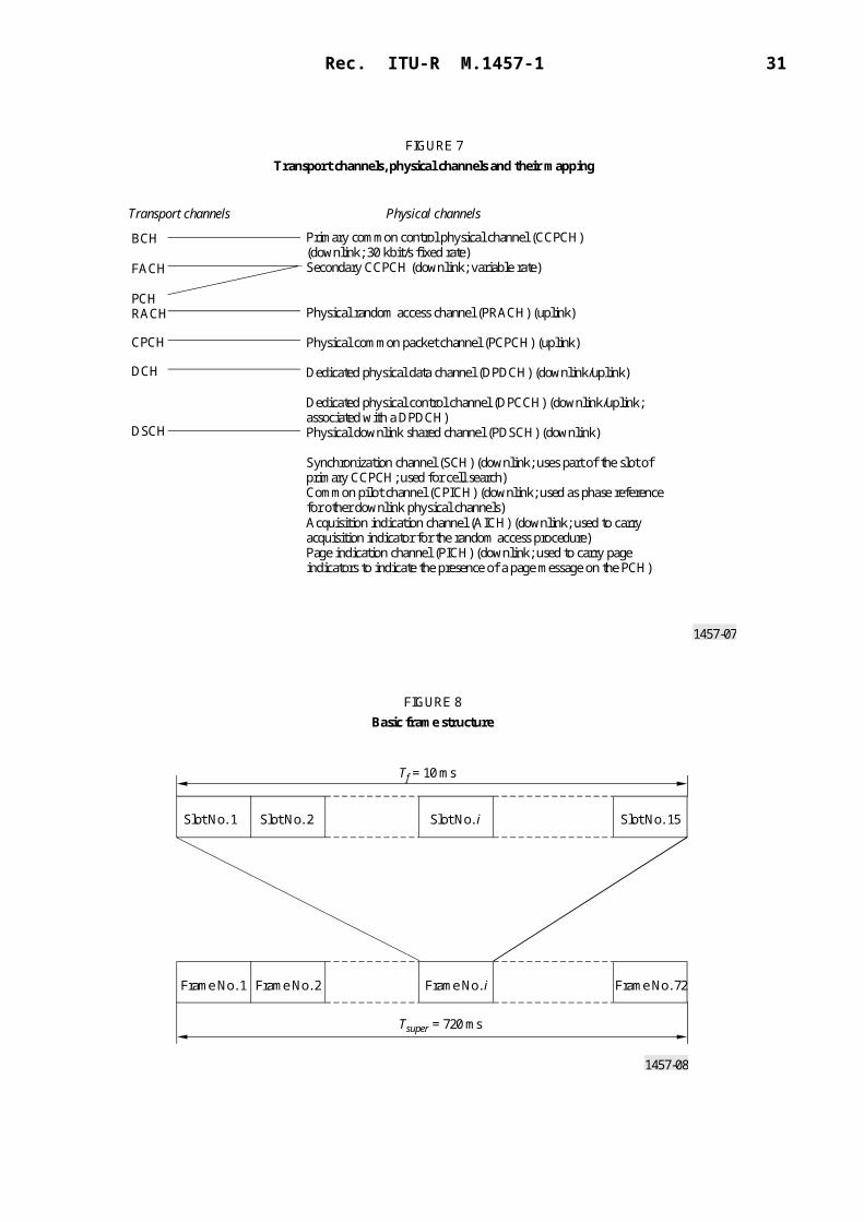
5.1.1.3.3 Transport channels to physical channel mapping
The transport channels are mapped onto the physical channels. Figure 7 shows the different physical channels and summarizes the mapping of transport channels onto physical channels. Each physical channel has its tailored slot content. The slot content for the DCH is shown in § 5.1.1.3.4.
5.1.1.3.4 Physical frame structure
The basic physical frame rate is 10 ms with 15 slots. Figure 8 shows the frame structure.
Figure 9 shows the content for a slot used by the DCH. The uplink physical channels DPDCH and DPCCH are I/Q multiplexed while the downlink channels are time multiplexed. The DPDCH, the channel where the user data is transmitted on, is always associated with a DPCCH containing Layer 1 control information. The transport format combination indicator (TFCI) field is used for indicating the demultiplexing scheme of the data stream. The TFCI field does not exist for combinations that are static (i.e. fixed bit rate allocations) or blind transport format detection is employed. The feedback information (FBI) field is used for transmit and site diversity functions. The transmit power control (TPC) bits are used for power control.
Transport channel Type and direction Used for
DCH (dedicated channel) Dedicated; uplink and downlink
User or control information to a UE (entire cell or part of cell (lobe-forming))
BCH (broadcast channel) Common; downlink Broadcast system and cell specific information
FACH (forward access channel) Common; downlink Control information when system knows UE location or short user packets to a UE
PCH (paging channel) Common; downlink Control information to UEs when good sleep mode properties are needed, e.g. idle mode operation
RACH (random access channel) Common; uplink Control information or short user packets from an UE
CPCH (common packet channel)
Common; uplink FDD only. Short and medium sized user packets. Always associated with a downlink channel for power control
DSCH (downlink shared channel)
Common; downlink Carries dedicated user data and control information using a shared channel.
Rec. ITU-R M.1457-1 17
1457-07
Primary common control physical channel (CCPCH)(downlink; 30 kbit/s fixed rate)Secondary CCPCH (downlink; variable rate)
Physical random access channel (PRACH) (uplink)
Physical common packet channel (PCPCH) (uplink)
Dedicated physical data channel (DPDCH) (downlink/uplink)
Dedicated physical control channel (DPCCH) (downlink/uplink;associated with a DPDCH)Physical downlink shared channel (PDSCH) (downlink)
Synchronization channel (SCH) (downlink; uses part of the slot ofprimary CCPCH; used for cell search)Common pilot channel (CPICH) (downlink; used as phase referencefor other downlink physical channels)Acquisition indication channel (AICH) (downlink; used to carryacquisition indicator for the random access procedure)Page indication channel (PICH) (downlink; used to carry pageindicators to indicate the presence of a page message on the PCH)
BCH
FACH
PCHRACH
CPCH
DCH
DSCH
Transport channels Physical channels
FIGURE 7Transport channels, physical channels and their mapping
1457-08
Tf = 10 ms
Tsuper = 720 ms
Slot No. 1 Slot No. 2 Slot No. i Slot No. 15
Frame No. 1 Frame No. 2 Frame No. i Frame No. 72
FIGURE 8Basic frame structure

18 Rec. ITU-R M.1457-1
1457-09
NTFCI bits
FIGURE 9The slot content for the DPDCH/DPCCH
DPCCH DPDCH DPCCH DPDCH DPCCH
Ndata1 bits NTPC bits Ndata2 bitsTFCI Data 1 TPC Data 2
Npilot bitsPilot
NTFCI bits
Ndata bits
NTPC bitsTFCI
Data
TPCNpilot bits
PilotNFBI bits
FBIDPCCH
DPDCH
FDDdownlink
FDDuplink
Tslot = 2 560 chips, 10 2k bits (k = 0, ..., 7)
Tslot = 2 560 chips, 10 2k bits (k = 0, ..., 6)
For the uplink, the DPDCH bit rate can vary between 15 up to 960 kbit/s using spreading factors (SFs) (256 down to 4. To obtain higher bit rates for a user several physical channels can be used. The bit rate of the DPCCH is fixed to 15 kbit/s. For the downlink the DPDCH bit rate is variable between 15 up to 1 920 kbit/s with a SF ranging from 512 down to 4. Note that the symbol bit rate is equal to the channel bit rate for the uplink while it is half of the channel bit rate for the downlink.
A CPICH is defined. It is an unmodulated downlink channel, that is the phase reference for other downlink physical channels. There is always one primary CPICH in each cell. There may also be additional secondary CPICHs in a cell.
To be able to support inter-frequency handover as well as measurements on other carrier frequencies or carriers of other systems, like GSM, a compressed mode of operation is defined. The function is implemented by having some slots empty, but without deleting any user data. Instead the user data is transmitted in the remaining slots. The number of slots that is not used can be variable with a minimum of three slots (giving minimum idle lengths of at least 1.73 ms). The slots can be empty either in the middle of a frame or at the end and in the beginning of the consecutive frame. If and how often is controlled by the RRC functionality in Layer 3.
5.1.1.3.5 Spreading, modulation and pulse shaping
Uplink
Spreading consists of two operations. The first is the channelization operation, which transforms every data symbol into a number of chips, thus increasing the bandwidth of the signal. The number of chips per data symbol is called the SF. The second operation is the scrambling operation, where a scrambling code is applied to the spread signal.

Rec. ITU-R M.1457-1 19
In the channelization operation, data symbol on so-called I- and Q-branches are independently multiplied with a code. The channelization codes are orthogonal variable spreading factor (OVSF) codes that preserve the orthogonality between a user's different physical channels. With the scrambling operation, the resultant signals on the I- and Q-branches are further multiplied by complex-valued scrambling code, where I and Q denote real and imaginary parts, respectively. Note that before complex multiplication binary values 0 and 1 are mapped to 1 and – 1, respectively. Figure 10 illustrates the spreading and modulation for the case of multiple uplink DPDCHs. Note that this figure only shows the principle, and does not necessarily describe an actual implementation. Modulation is dual-channel QPSK (i.e. separate BPSK on I- and Q-channel), where the uplink DPDCH and DPCCH are mapped to the I and Q branch respectively. The I and Q branches are then spread to the chip rate with two different channelization codes and subsequently complex scrambled by a UE specific complex scrambling code Cscramb. There are 224 uplink-scrambling codes. Either short (256 chips from the family of S(2) codes) or long (38 400 chips equal to one frame length, gold code-based) scrambling codes is used on the uplink. The short scrambling code is typically used in cells where the BS is equipped with an advanced receiver, such as a multi-user detector or interference canceller whereas the long codes gives better interference averaging properties.
The pulse-shaping filters are root-raised cosine with roll-off = 0.22 in the frequency domain.
The modulation of both DPCCH and DPDCH is BPSK. The modulated DPCCH is mapped to the Q-branch, while the first DPDCH is mapped to the I-branch. Subsequently added DPDCHs are mapped alternatively to the I- or Q-branches.
Downlink
Figure 11 illustrates the spreading and modulation for the downlink DPDCH/DPCCH. Data modulation is QPSK where each pair of two bits are serial-to-parallel (S/P) converted and mapped to the I- and Q-branch respectively. The I- and Q-branch are then spread to the chip rate with the same channelization code Cch (real spreading) and subsequently scrambled by the scrambling code Cscramb (complex scrambling).
The channelization codes are the same codes as used in the uplink that preserve the orthogonality between downlink channels of different rates and SFs. There are a total of 512 512 262 144 scrambling codes, numbered 0 to 262 143. The scrambling codes are divided into 512 sets each of a primary scrambling code and 511 secondary scrambling codes. Each cell is allocated one and only one primary scrambling code. The primary CCPCH is always transmitted using the primary scrambling code. The other downlink physical channels can be transmitted with either the primary scrambling code or a secondary scrambling code from the set associated with the primary scrambling code of the cell.
The pulse-shaping filters are root-raised cosine with roll-off 0.22 in the frequency domain.

20 Rec. ITU-R M.1457-1
1457-10
DPDCH1
(BPSK)
DPDCH3
(BPSK)
DPDCHN–1
(BPSK)
DPDCH2
(BPSK)
DPDCH4
(BPSK)
DPDCHN
(BPSK)
DPCCH
(BPSK)
Cch.d2
Cch.d4
2
4
Cch.dN
Cch.dc
N
c
Cch.d1
Cch.d3
1
3
Cch.dN–1
N–1
*j
I + jQ
Cscramb
cos(t)
–sin(t)
p(t)
p(t)Real
Imaginary
OVSF channelization codes DPDCH gains
FIGURE 10Spreading/modulation for uplink DPDCH/DPCCH

Rec. ITU-R M.1457-1 21
1457-11
Cch.2
*j
I + jQ
Cscramb
cos(t)
–sin(t)
p(t)
p(t)Real
Imaginary
FIGURE 11Spreading/modulation for downlink DPDCH/DPCCH
Cch.1
Cch.NS/P
S/P
S/P
DPDCHN
DPDCH2
DPDCH1/DPCCH
I
Q
5.1.1.4 Layer 2
5.1.1.4.1 MAC layer
The MAC sublayer is responsible for the handling of the data streams coming from the RLC and RRC sublayers. It provides an unacknowledged transfer mode service to the upper layers. The interface to the RLC sublayer is through logical channel service access points. It also re-allocates radio resources on request by the RRC sublayer as well as provides measurements to the upper layers. The logical channels are divided into control channels and traffic channels. Thus, the functionality handles issues like:– mapping of the different logical channels to the appropriate transport channels and selection
of appropriate transport format for the transport channels based on the instantaneous source bit rate. It also performs the multiplexing/demultiplexing of the PDUs to/from transport blocks which are thereafter further treated by the physical layer;
– performs dynamic switching between common and dedicated transport channels based on information from the RRC sublayer;
– handles priority issues for services to one UE according to information from higher layers and physical layer (e.g. available transmit power level) as well as priority handling between UEs by means of dynamic scheduling in order to increase spectrum efficiency;
– monitor traffic volume that can be used by the RRC sublayer.
22 Rec. ITU-R M.1457-1
Figure 12 shows the possibilities of mapping the logical dedicated traffic channel (DTCH) onto transport channels. There are possibilities to map onto shared transport channels as well as dedicated transport channels. The choice of mapping could be determined on e.g. amount of traffic a user creates.
1457-12
DTCH-SAP Logical channel
MAC SAP
UE side
CPCH RACH FACH DSCH DCH Transportchannels
FIGURE 12The possible transport channel mappings of the DTCH(The arrows show the direction of the channel (UE side).
The directions are reversed from the network side)
5.1.1.4.2 RLC sublayer
The RLC sublayer provides three different types of data transfer modes:– Transparent data transfer. This service transmits higher layer PDUs without adding any
protocol information, possibly including segmentation/reassemble functionality.– Unacknowledged data transfer. This service transmits higher layer PDUs without
guaranteeing delivery to the peer entity. The unacknowledged data transfer mode has the following characteristics:a) detection of erroneous data: The RLC sublayer shall deliver only those SDUs to the
receiving higher layer that are free of transmission errors by using the sequence-number check function;
b) unique delivery: The RLC sublayer shall deliver each SDU only once to the receiving upper layer using duplication detection function;
c) immediate delivery: The receiving RLC sublayer entity shall deliver a SDU to the higher layer receiving entity as soon as it arrives at the receiver.
– Acknowledged data transfer. This service transmits higher layer PDUs and guarantees delivery to the peer entity. In case RLC is unable to deliver the data correctly, the user of RLC at the transmitting side is notified. For this service, both in-sequence and out-of-sequence delivery are supported. In many cases a higher layer protocol can restore the order of its PDUs. As long as the out-of-sequence properties of the lower layer are known and controlled (i.e. the higher layer protocol will not immediately request retransmission of a missing PDU) allowing out-of-sequence delivery can save memory space in the receiving RLC. The acknowledged data transfer mode has the following characteristics:a) error-free delivery: error-free delivery is ensured by means of retransmission. The
receiving RLC entity delivers only error-free SDUs to the higher layer;b) unique delivery: the RLC sublayer shall deliver each SDU only once to the receiving
upper layer using duplication detection function;

Rec. ITU-R M.1457-1 23
c) in-sequence delivery: RLC sublayer shall provide support for in-order delivery of SDUs, i.e. RLC sublayer should deliver SDUs to the receiving higher layer entity in the same order as the transmitting higher layer entity submits them to the RLC sublayer;
d) out-of-sequence delivery: alternatively to in-sequence delivery, it shall also be possible to allow that the receiving RLC entity delivers SDUs to higher layer in different order than submitted to RLC sublayer at the transmitting side.
It also provides for RLC connection establishment/release. As well as QoS setting and notification to higher layers in case of unrecoverable errors.
An example of the data flow for non-transparent (acknowledged/unacknowledged) data transfer is shown in Fig. 5.
5.1.1.5 Layer 3 (RRC sublayer)
The RRC sublayer handles the control plane signalling of Layer 3 between the UEs and the radio interface. In addition to the relation with the upper layers (such as CN) the following main functions are performed:– Broadcast of information provided by the non-access stratum (CN) – The RRC layer
performs system information broadcasting from the network to all UEs. The system information is normally repeated on a regular basis. This function supports broadcast of higher layer (above RRC) information. This information may be cell specific or not. As an example RRC may broadcast CN location service area information related to some specific cells.
– Broadcast of information related to the access stratum – The RRC layer performs system information broadcasting from the network to all UEs. This function supports broadcast of typically cell-specific information.
– Establishment, maintenance and release of an RRC connection between the UE and the radio access network – The establishment of an RRC connection is initiated by a request from higher layers at the UE side to establish the first signalling connection for the UE. The establishment of an RRC connection includes an optional cell re-selection, an admission control, and a Layer 2 signalling link establishment.
– Establishment, reconfiguration and release of radio access bearers – The RRC layer will, on request from higher layers, perform the establishment, reconfiguration and release of radio access bearers in the user plane. A number of radio access bearers can be established to an UE at the same time. At establishment and reconfiguration, the RRC layer performs admission control and selects parameters describing the radio access bearer processing in Layer 2 and Layer 1, based on information from higher layers.
– Assignment, reconfiguration and release of radio resources for the RRC connection – The RRC layer handles the assignment of radio resources (e.g. codes) needed for the RRC connection including needs from both the control and user plane. The RRC layer may reconfigure radio resources during an established RRC connection. This function includes coordination of the radio resource allocation between multiple radio bearers related to the same RRC connection. RRC controls the radio resources in the uplink and downlink such

24 Rec. ITU-R M.1457-1
that UE and the radio access network can communicate using unbalanced radio resources (asymmetric uplink and downlink). RRC signals to the UE to indicate resource allocations for purposes of handover to GSM or other radio systems.
– RRC connection mobility functions – The RRC layer performs evaluation, decision and execution related to RRC connection mobility during an established RRC connection, such as handover, preparation of handover to GSM or other systems, cell re-selection and cell/paging area update procedures, based on e.g. measurements done by the UE.
– Paging/notification – The RRC layer can broadcast paging information from the network to selected UEs. The RRC layer can also initiate paging during an established RRC connection.
– Control of requested QoS – This function ensures that the QoS requested for the radio access bearers can be met. This includes the allocation of a sufficient number of radio resources.
– UE measurement reporting and control of the reporting – The measurements performed by the UE are controlled by the RRC layer, in terms of what to measure, when to measure and how to report, including both this radio interface and other systems. The RRC layer also performs the reporting of the measurements from the UE to the network.
– Outer loop power control – The RRC layer controls setting of the target of the closed-loop power control.
– Control of ciphering – The RRC layer provides procedures for setting of ciphering (on/off) between the UE and the radio access network.
– Initial cell selection and re-selection in idle mode – Selection of the most suitable cell based on idle mode measurements and cell selection criteria.
– Arbitration of the radio resource allocation between the cells – This function shall ensure optimal performance of the overall radio access network capacity.
5.1.1.6 Summary of major technical parameters
Parameter Value Reference to § 5.1.2
Multiple access technique and duplexing scheme
Multiple access: direct sequence-CDMADuplexing: FDD
5.1.2.1.1
Chip rate (Mchip/s) 3.84 5.1.2.1.4
Frame length and structure Frame length: 10 ms15 slots per frame, each 666.666 s
5.1.2.1.2
Occupied bandwidth Less than 5 MHz 5.1.2.4.1, 5.1.2.4.3
Adjacent channel leakage power ratio (ACLR) (transmitter side)
UE (UE power class: 21 dBm):ACLR (5 MHz) 33 dBACLR (10 MHz) 43 dB
BS: ACLR (5 MHz) 45 dBACLR (10 MHz) 50 dB
5.1.2.4.1
5.1.2.4.3
Adjacent channel selectivity (ACS) (receiver side)
UE: ACS (5 MHz) 33 dBBS: ACS (5 MHz) 45 dB
5.1.2.4.15.1.2.4.3
Random access mechanism Acquisition indication based random-access mechanism with power ramping on preamble followed by message
5.1.2.1.25.1.2.1.5
Pilot structure Uplink: dedicated pilotsDownlink: common and/or dedicated pilots
5.1.2.1.2
Inter-base station asynchronous/synchronous operation
Asynchronous;synchronous (optional)
5.1.2.1.55.1.2.4.3

Rec. ITU-R M.1457-1 25
5.1.2 Detailed specification of the radio interface
The standards contained in this section are derived from the global core specifications for IMT-2000 contained at http://ties.itu.int/u/itu-r/ede/rsg8/wp8f/rtech/GCS1457-0/.
5.1.2.1 25.200 series
5.1.2.1.1 25.201 Physical layer – General description
This specification gives general description of the physical layer of the UTRA radio interface.
5.1.2.1.2 25.211 Physical channels and mapping of transport channels onto physical channels (FDD)
This specification describes the characteristics of the Layer 1 transport channels and physical channels in the FDD mode of UTRA. The main objectives of the specification are to be a part of the full description of the UTRA Layer 1, and to serve as a basis for the drafting of the actual technical specification (TS).
Document No. Version Status Issued date Location(1)
(2) ARIB ARIB STD-T-63-25.201 3.0.1 Approved by ARIB Standard Assembly
2000-03-31 http://www.arib.or.jp/IMT-2000/ARIB-STD/STD-T63/25.201.html
CWTS CWTS STD-DS-25.201 2000 Approved 2000-03 http://www.cwts.org/imt2000/DS
ETSI ETSI TS 125 201 3.0.1 ETSI published 2000-01 http://webapp.etsi.org/pda/home.asp?wki_id=7177
T1 T1TR3GPP 25.201 310 Approved 2000-06 https://www.atis.org/atis/docstore/doc_display.asp?ID=785
TTA TTAE.3G-25.201(F) 1 TA approved 2000-03-28 http://www.tta.or.kr/imt2000/STD-DS/25201.zip
(1) The relevant SDOs should make their reference material available from their Web site.(2) This information was supplied by the recognized external organizations and relates to their own deliverables of the transposed
global core specification.
Document No. Version Status Issued date Location(1)
(2) ARIB ARIB STD-T-63-25.211 3.1.1 Approved by ARIB Standard Assembly
2000-03-31 http://www.arib.or.jp/IMT-2000/ARIB-STD/STD-T63/25.211.html
CWTS CWTS STD-DS-25.211 2000 Approved 2000-03 http://www.cwts.org/imt2000/DS
ETSI ETSI TS 125 211 3.1.1 ETSI published 2000-01 http://webapp.etsi.org/pda/home.asp?wki_id=7734
T1 T1TR3GPP 25.211 330 Approved 2000-06 https://www.atis.org/atis/docstore/doc_display.asp?ID=786
TTA TTAE.3G-25.211(F) 1 TA approved 2000-03-28 http://www.tta.or.kr/imt2000/STD-DS/25211.zip
(1), (2) See Notes (1) and (2), § 5.1.2.1.1.

26 Rec. ITU-R M.1457-1
5.1.2.1.3 25.212 Multiplexing and channel coding (FDD)
This specification describes the characteristics of the Layer 1 multiplexing and channel coding in the FDD mode of UTRA.
5.1.2.1.4 25.213 Spreading and modulation (FDD)
This specification describes spreading and modulation for UTRA physical layer FDD mode.
5.1.2.1.5 25.214 Physical layer procedures (FDD)
This specification describes and establishes the characteristics of the physical layer procedures in the FDD mode of UTRA.
Document No. Version Status Issued date Location(1)
(2) ARIB ARIB STD-T-63-25.212 3.1.1 Approved by ARIB Standard Assembly
2000-03-31 http://www.arib.or.jp/IMT-2000/ARIB-STD/STD-T63/25.212.html
CWTS CWTS STD-DS-25.212 2000 Approved 2000-03 http://www.cwts.org/imt2000/DS
ETSI ETSI TS 125 212 3.1.1 ETSI published 2000-01 http://webapp.etsi.org/pda/home.asp?wki_id=7735
T1 T1TR3GPP 25.212 330 Approved 2000-06 https://www.atis.org/atis/docstore/doc_display.asp?ID=787
TTA TTAE.3G-25.212(F) 1 TA approved 2000-03-28 http://www.tta.or.kr/imt2000/STD-DS/25212.pdf
(1), (2) See Notes (1) and (2), § 5.1.2.1.1.
Document No. Version Status Issued date Location(1)
(2) ARIB ARIB STD-T-63-25.213 3.1.1 Approved by ARIB Standard Assembly
2000-03-31 http://www.arib.or.jp/IMT-2000/ARIB-STD/STD-T63/25.213.html
CWTS CWTS STD-DS-25.213 2000 Approved 2000-03 http://www.cwts.org/imt2000/DS
ETSI ETSI TS 125 213 3.1.1 ETSI published 2000-01 http://webapp.etsi.org/pda/home.asp?wki_id=7736
T1 T1TR3GPP 25.213 330 Approved 2000-06 https://www.atis.org/atis/docstore/doc_display.asp?ID=788
TTA TTAE.3G-25.213(F) 1 TA approved 2000-03-28 http://www.tta.or.kr/imt2000/STD-DS/25213.zip
(1), (2) See Notes (1) and (2), § 5.1.2.1.1.
Document No. Version Status Issued date Location(1)
(2) ARIB ARIB STD-T-63-25.214 3.1.1 Approved by ARIB Standard Assembly
2000-03-31 http://www.arib.or.jp/IMT-2000/ARIB-STD/STD-T63/25.214.html
CWTS CWTS STD-DS-25.214 2000 Approved 2000-03 http://www.cwts.org/imt2000/DS
ETSI ETSI TS 125 214 3.1.1 ETSI published 2000-01 http://webapp.etsi.org/pda/home.asp?wki_id=7737
T1 T1TR3GPP 25.214 330 Approved 2000-06 https://www.atis.org/atis/docstore/doc_display.asp?ID=789
TTA TTAE.3G-25.214(F) 1 TA approved 2000-03-28 http://www.tta.or.kr/imt2000/STD-DS/25214.zip
(1), (2) See Notes (1) and (2), § 5.1.2.1.1.

Rec. ITU-R M.1457-1 27
5.1.2.1.6 25.215 Physical layer – Measurements (FDD)
This specification describes the measurements done at the UE and network in order to support operation in idle mode and connected mode for FDD mode.
5.1.2.2 25.300 series
5.1.2.2.1 25.301 Radio interface protocol architecture
This specification describes an overview and overall description of the UE-UTRAN radio interface protocol architecture. Details of the radio protocols will be specified in companion documents.
5.1.2.2.2 25.302 Services provided by the physical layer
This specification describes a technical specification of the services provided by the physical layer of UTRA to upper layers.
Document No. Version Status Issued date Location(1)
(2) ARIB ARIB STD-T-63-25.215 3.1.1 Approved by ARIB Standard Assembly
2000-03-31 http://www.arib.or.jp/IMT-2000/ARIB-STD/STD-T63/25.215.html
CWTS CWTS STD-DS-25.215 2000 Approved 2000-03 http://www.cwts.org/imt2000/DSETSI ETSI TS 125 215 3.1.1 ETSI published 2000-01 http://webapp.etsi.org/pda/
home.asp?wki_id=8877T1 T1TR3GPP 25.215 330 Approved 2000-06 https://www.atis.org/atis/docstore/
doc_display.asp?ID=790TTA TTAE.3G-25.215(F) 1 TA approved 2000-03-28 http://www.tta.or.kr/imt2000/STD-
DS/25215.zip
(1), (2) See Notes (1) and (2), § 5.1.2.1.1.
Document No. Version Status Issued date Location(1)
(2) ARIB ARIB STD-T-63-25.301 3.3.0 Approved by ARIB Standard Assembly
2000-03-31 http://www.arib.or.jp/IMT-2000/ARIB-STD/STD-T63/25.301.html
CWTS CWTS STD-DS-25.301 2000 Approved 2000-03 http://www.cwts.org/imt2000/DSETSI ETSI TS 125 301 3.3.0 ETSI published 2000-01 http://webapp.etsi.org/pda/
home.asp?wki_id=7743T1 T1TR3GPP 25.301 350 Approved 2000-06 https://www.atis.org/atis/docstore/
doc_display.asp?ID=796TTA TTAE.3G-25.301(F) 1 TA approved 2000-03-28 http://www.tta.or.kr/imt2000/STD-
DS/25301.zip
(1), (2) See Notes (1) and (2), § 5.1.2.1.1.
Document No. Version Status Issued date Location(1)
(2) ARIB ARIB STD-T-63-25.302 3.3.0 Approved by ARIB Standard Assembly
2000-03-31 http://www.arib.or.jp/IMT-2000/ARIB-STD/STD-T63/25.302.html
CWTS CWTS STD-DS-25.302 2000 Approved 2000-03 http://www.cwts.org/imt2000/DSETSI ETSI TS 125 302 3.3.0 ETSI published 2000-01 http://webapp.etsi.org/pda/
home.asp?wki_id=7744T1 T1TR3GPP 25.302 350 Approved 2000-06 https://www.atis.org/atis/docstore/
doc_display.asp?ID=797TTA TTAE.3G-25.302(F) 1 TA approved 2000-03-28 http://www.tta.or.kr/imt2000/STD-
DS/25302.zip
(1), (2) See Notes (1) and (2), § 5.1.2.1.1.

28 Rec. ITU-R M.1457-1
5.1.2.2.3 25.303 Interlayer procedures in connected mode
This specification describes informative interlayer procedures to perform the required tasks.
This specification attempts to provide a comprehensive overview of the different states and transitions within the connected mode of universal mobile telecommunications system (UMTS) terminal.
5.1.2.2.4 25.304 UE procedures in idle mode and procedures for cell reselection in connected mode
This specification describes the overall idle mode process for the UE and the functional division between the non-access stratum and access stratum in the UE. The UE is in idle mode when the connection of the UE is closed on all layers, e.g. there is neither an MM connection nor an RRC connection.
This specification presents also examples of inter-layer procedures related to the idle mode processes and describes idle mode functionality of a dual mode UMTS/GSM UE.
Document No. Version Status Issued date Location(1)
(2) ARIB ARIB STD-T-63-25.303 3.2.0 Approved by ARIB Standard Assembly
2000-03-31 http://www.arib.or.jp/IMT-2000/ARIB-STD/STD-T63/25.303.html
CWTS CWTS STD-DS-25.303 2000 Approved 2000-03 http://www.cwts.org/imt2000/DS
ETSI ETSI TS 125 303 3.2.0 ETSI published 2000-01 http://webapp.etsi.org/pda/home.asp?wki_id=7745
T1 T1TR3GPP 25.303 340 Approved 2000-06 https://www.atis.org/atis/docstore/doc_display.asp?ID=798
TTA TTAE.3G-25.303(F) 1 TA approved 2000-03-28 http://www.tta.or.kr/imt2000/STD-DS/25303.zip
(1), (2) See Notes (1) and (2), § 5.1.2.1.1.
Document No. Version Status Issued date Location(1)
(2) ARIB ARIB STD-T-63-25.304 3.1.0 Approved by ARIB Standard Assembly
2000-03-31 http://www.arib.or.jp/IMT-2000/ARIB-STD/STD-T63/25.304.html
CWTS CWTS STD-DS-25.304 2000 Approved 2000-03 http://www.cwts.org/imt2000/DS
ETSI ETSI TS 125 304 3.1.0 ETSI published 2000-01 http://webapp.etsi.org/pda/home.asp?wki_id=7746
T1 T1TR3GPP 25.304 330 Approved 2000-06 https://www.atis.org/atis/docstore/doc_display.asp?ID=799
TTA TTAE.3G-25.304(F) 1 TA approved 2000-03-28 http://www.tta.or.kr/imt2000/STD-DS/25304.zip
(1), (2) See Notes (1) and (2), § 5.1.2.1.1.

Rec. ITU-R M.1457-1 29
5.1.2.2.5 25.321 Medium access control (MAC) protocol specification
This specification describes the MAC protocol.
5.1.2.2.6 25.322 Radio link control (RLC) protocol specification
This specification describes the RLC protocol.
5.1.2.2.7 25.331 Radio resource control (RRC) protocol specification
This specification describes the RRC protocol for the radio system. The scope of this specification contains also the information to be transported in a transparent container between source RNC and target RNC in connection to SRNC relocation.
Document No. Version Status Issued date Location(1)
(2) ARIB ARIB STD-T-63-25.321 3.2.0 Approved by ARIB Standard Assembly
2000-03-31 http://www.arib.or.jp/IMT-2000/ARIB-STD/STD-T63/25.321.html
CWTS CWTS STD-DS-25.321 2000 Approved 2000-03 http://www.cwts.org/imt2000/DS
ETSI ETSI TS 125 321 3.2.0 ETSI published 2000-01 http://webapp.etsi.org/pda/home.asp?wki_id=7747
T1 T1TR3GPP 25.321 340 Approved 2000-06 https://www.atis.org/atis/docstore/doc_display.asp?ID=800
TTA TTAE.3G-25.321(F) 1 TA approved 2000-03-28 http://www.tta.or.kr/imt2000/STD-DS/25321.zip
(1), (2) See Notes (1) and (2), § 5.1.2.1.1.
Document No. Version Status Issued date Location(1)
(2) TTC JP-3GA-25.322(R99) 1 TTC Technical Assembly approved
2000-03-31 http://www.ttc.or.jp/imt/std/jp25322r99.pdf
CWTS CWTS STD-DS-25.322 2000 Approved 2000-03 http://www.cwts.org/imt2000/DS
ETSI ETSI TS 125 322 3.1.2 ETSI published 2000-01 http://webapp.etsi.org/pda/home.asp?wki_id=7748
T1 T1TR3GPP 25.322 330 Approved 2000-06 https://www.atis.org/atis/docstore/doc_display.asp?ID=801
TTA TTAE.3G-25.322(F) 1 TA approved 2000-03-28 http://www.tta.or.kr/imt2000/STD-DS/25322.zip
(1), (2) See Notes (1) and (2), § 5.1.2.1.1.
Document No. Version Status Issued date Location(1)
(2) TTC JP-3GA-25.331(R99) 1 TTC Technical Assembly approved
2000-03-31 http://www.ttc.or.jp/imt/std/jp25331r99.pdf
CWTS CWTS STD-DS-25.331 2000 Approved 2000-03 http://www.cwts.org/imt2000/DS
ETSI ETSI TS 125 331 3.1.0 ETSI published 2000-01 http://webapp.etsi.org/pda/home.asp?wki_id=7749
T1 T1TR3GPP 25.331 330 Approved 2000-06 https://www.atis.org/atis/docstore/doc_display.asp?ID=802
TTA TTAE.3G-25.331(F) 1 TA approved 2000-03-28 http://www.tta.or.kr/imt2000/STD-DS/25331.zip
(1), (2) See Notes (1) and (2), § 5.1.2.1.1.

30 Rec. ITU-R M.1457-1
5.1.2.3 25.400 series
5.1.2.3.1 25.401 UMTS terrestrial radio access network (UTRAN) overall description
This specification describes the overall architecture of the UTRAN, including internal interfaces and assumptions on the radio and Iu interfaces.
5.1.2.3.2 25.410 UTRAN Iu interface: general aspects and principles
This specification describes an introduction to the 25.41x series of technical specifications that define the Iu interface for the interconnection of RNC component of the UTRAN to the CN.
5.1.2.3.3 25.411 UTRAN Iu interface Layer 1
This specification describes the standards allowed to implement Layer 1 on the Iu interface.
The specification of transmission delay requirements and O&M requirements are not in the scope of this specification.
Document No. Version Status Issued date Location(1)
(2) ARIB ARIB STD-T-63-25.401 3.1.0 Approved by ARIB Standard Assembly
2000-03-31 http://www.arib.or.jp/IMT-2000/ARIB-STD/STD-T63/25.401.html
CWTS CWTS STD-DS-25.401 2000 Approved 2000-03 http://www.cwts.org/imt2000/DSETSI ETSI TS 125 401 3.1.0 ETSI published 2000-01 http://webapp.etsi.org/pda/
home.asp?wki_id=7750T1 T1TR3GPP 25.401 330 Approved 2000-06 https://www.atis.org/atis/docstore/
doc_display.asp?ID=803TTA TTAE.3G-25.401(F) 1 TA approved 2000-03-28 http://www.tta.or.kr/imt2000/STD-
DS/25401.zip
(1), (2) See Notes (1) and (2), § 5.1.2.1.1.
Document No. Version Status Issued date Location(1)
(2) TTC JP-3GA-25.410(R99) 1 TTC Technical Assembly approved
2000-03-31 http://www.ttc.or.jp/imt/std/jp25410r99.pdf
CWTS CWTS STD-DS-25.410 2000 Approved 2000-03 http://www.cwts.org/imt2000/DSETSI ETSI TS 125 410 3.1.0 ETSI published 2000-01 http://webapp.etsi.org/pda/
home.asp?wki_id=7751T1 T1TR3GPP 25.410 320 Approved 2000-03 https://www.atis.org/atis/docstore/
doc_display.asp?ID=804TTA TTAE.3G-25.410(F) 1 TA approved 2000-03-28 http://www.tta.or.kr/imt2000/STD-
DS/25410.zip
(1), (2) See Notes (1) and (2), § 5.1.2.1.1.
Document No. Version Status Issued date Location(1)
(2) TTC JP-3GA-25.411(R99) 1 TTC Technical Assembly approved
2000-03-31 http://www.ttc.or.jp/imt/std/jp25411r99.pdf
CWTS CWTS STD-DS-25.411 2000 Approved 2000-03 http://www.cwts.org/imt2000/DSETSI ETSI TS 125 411 3.1.0 ETSI published 2000-01 http://webapp.etsi.org/pda/
home.asp?wki_id=7752T1 T1TR3GPP 25.411 320 Approved 2000-03 https://www.atis.org/atis/docstore/
doc_display.asp?ID=805TTA TTAE.3G-25.411(F) 1 TA approved 2000-03-28 http://www.tta.or.kr/imt2000/STD-
DS/25411.zip
(1), (2) See Notes (1) and (2), § 5.1.2.1.1.
Rec. ITU-R M.1457-1 31
5.1.2.3.4 25.412 UTRAN Iu interface signalling transport
This specification describes the standards for user data transport protocols and related signalling protocols to establish user plane transport bearers.
5.1.2.3.5 25.413 UTRAN Iu interface radio access network application part (RANAP) signalling
This specification describes the signalling between the CN and the UTRAN over the Iu interface.
5.1.2.3.6 25.414 UTRAN Iu interface data transport and transport signalling
This specification describes the standards for user data transport protocols and related signalling protocols to establish user plane transport bearers.
Document No. Version Status Issued date Location(1)
(2) TTC JP-3GA-25.412(R99) 1 TTC Technical Assembly approved
2000-03-31 http://www.ttc.or.jp/imt/std/jp25412r99.pdf
CWTS CWTS STD-DS-25.412 2000 Approved 2000-03 http://www.cwts.org/imt2000/DS
ETSI ETSI TS 125 412 3.2.0 ETSI published 2000-01 http://webapp.etsi.org/pda/home.asp?wki_id=7753
T1 T1TR3GPP 25.412 340 Approved 2000-06 https://www.atis.org/atis/docstore/doc_display.asp?ID=806
TTA TTAE.3G-25.412(F) 1 TA approved 2000-03-28 http://www.tta.or.kr/imt2000/STD-DS/25412.zip
(1), (2) See Notes (1) and (2), § 5.1.2.1.1.
Document No. Version Status Issued date Location(1)
(2) TTC JP-3GA-25.413(R99) 1 TTC Technical Assembly approved
2000-03-31 http://www.ttc.or.jp/imt/std/jp25413r99.pdf
CWTS CWTS STD-DS-25.413 2000 Approved 2000-03 http://www.cwts.org/imt2000/DS
ETSI ETSI TS 125 413 3.0.0 ETSI published 2000-01 http://webapp.etsi.org/pda/home.asp?wki_id=7754
T1 T1TR3GPP 25.413 320 Approved 2000-06 https://www.atis.org/atis/docstore/doc_display.asp?ID=807
TTA TTAE.3G-25.413(F) 1 TA approved 2000-03-28 http://www.tta.or.kr/imt2000/STD-DS/25413.zip
(1), (2) See Notes (1) and (2), § 5.1.2.1.1.
Document No. Version Status Issued date Location(1)
(2) TTC JP-3GA-25.414(R99) 1 TTC Technical Assembly approved
2000-03-31 http://www.ttc.or.jp/imt/std/jp25414r99.pdf
CWTS CWTS STD-DS-25.414 2000 Approved 2000-03 http://www.cwts.org/imt2000/DS
ETSI ETSI TS 125 414 3.2.0 ETSI published 2000-01 http://webapp.etsi.org/pda/home.asp?wki_id=7755
T1 T1TR3GPP 25.414 340 Approved 2000-06 https://www.atis.org/atis/docstore/doc_display.asp?ID=808
TTA TTAE.3G-25.414(F) 1 TA approved 2000-03-28 http://www.tta.or.kr/imt2000/STD-DS/25414.zip
(1), (2) See Notes (1) and (2), § 5.1.2.1.1.

32 Rec. ITU-R M.1457-1
5.1.2.3.7 25.415 UTRAN Iu interface user plane protocols
This specification describes the protocols being used to transport and control over the Iu interface, the Iu user data streams.
5.1.2.3.8 25.420 UTRAN Iur interface: general aspects and principles
This specification describes an introduction to the TSG RAN TS 25.42x series of technical specifications that define the Iur interface. It is a logical interface for the interconnection of two RNC components of the UTRAN.
5.1.2.3.9 25.421 UTRAN Iur interface Layer 1
This specification describes the standards allowed to implement Layer 1 on the Iur interface.
The specification of transmission delay requirements and O&M requirements are not in the scope of this specification.
Document No. Version Status Issued date Location(1)
(2) TTC JP-3GA-25.415(R99) 1 TTC Technical Assembly approved
2000-03-31 http://www.ttc.or.jp/imt/std/jp25415r99.pdf
CWTS CWTS STD-DS-25.415 2000 Approved 2000-03 http://www.cwts.org/imt2000/DSETSI ETSI TS 125 415 3.1.0 ETSI published 2000-01 http://webapp.etsi.org/pda/
home.asp?wki_id=7756T1 T1TR3GPP 25.415 330 Approved 2000-06 https://www.atis.org/atis/docstore/
doc_display.asp?ID=809TTA TTAE.3G-25.415(F) 1 TA approved 2000-03-28 http://www.tta.or.kr/imt2000/STD-
DS/25415.zip
(1), (2) See Notes (1) and (2), § 5.1.2.1.1.
Document No. Version Status Issued date Location(1)
(2) ARIB ARIB STD-T-63-25.420 3.0.0 Approved by ARIB Standard Assembly
2000-03-31 http://www.arib.or.jp/IMT-2000/ARIB-STD/STD-T63/25.420.html
CWTS CWTS STD-DS-25.420 2000 Approved 2000-03 http://www.cwts.org/imt2000/DSETSI ETSI TS 125 420 3.0.0 ETSI published 2000-01 http://webapp.etsi.org/pda/
home.asp?wki_id=7757T1 T1TR3GPP 25.420 310 Approved 2000-03 https://www.atis.org/atis/docstore/
doc_display.asp?ID=810TTA TTAE.3G-25.420(F) 1 TA approved 2000-03-28 http://www.tta.or.kr/imt2000/STD-
DS/25420.zip
(1), (2) See Notes (1) and (2), § 5.1.2.1.1.
Document No. Version Status Issued date Location(1)
(2) ARIB ARIB STD-T-63-25.421 3.0.0 Approved by ARIB Standard Assembly
2000-03-31 http://www.arib.or.jp/IMT-2000/ARIB-STD/STD-T63/25.421.html
CWTS CWTS STD-DS-25.421 2000 Approved 2000-03 http://www.cwts.org/imt2000/DSETSI ETSI TS 125 421 3.0.0 ETSI published 2000-01 http://webapp.etsi.org/pda/
home.asp?wki_id=7758T1 T1TR3GPP 25.421 300 Approved 1999-10 https://www.atis.org/atis/docstore/
doc_display.asp?ID=590TTA TTAE.3G-25.421(F) 1 TA approved 2000-03-28 http://www.tta.or.kr/imt2000/STD-
DS/25421.zip
(1), (2) See Notes (1) and (2), § 5.1.2.1.1.

Rec. ITU-R M.1457-1 33
5.1.2.3.10 25.422 UTRAN Iur interface signalling transport
This specification describes the standards for user data transport protocols and related signalling protocols to establish user plane transport bearers.
5.1.2.3.11 25.423 UTRAN Iur interface RNSAP signalling
This specification describes the radio network layer signalling procedures between RNCs in UTRAN.
5.1.2.3.12 25.424 UTRAN Iur interface data transport and transport signalling for common transport channel data streams
This specification describes the UTRAN RNS-RNS (Iur) interface data transport and transport signalling for common transport channel data streams.
Document No. Version Status Issued date Location(1)
(2) ARIB ARIB STD-T-63-25.422 3.2.0 Approved by ARIB Standard Assembly
2000-03-31 http://www.arib.or.jp/IMT-2000/ARIB-STD/STD-T63/25.422.html
CWTS CWTS STD-DS-25.422 2000 Approved 2000-03 http://www.cwts.org/imt2000/DSETSI ETSI TS 125 422 3.2.0 ETSI published 2000-01 http://webapp.etsi.org/pda/
home.asp?wki_id=7759T1 T1TR3GPP 25.422 340 Approved 2000-06 https://www.atis.org/atis/docstore/
doc_display.asp?ID=811TTA TTAE.3G-25.422(F) 1 TA approved 2000-03-28 http://www.tta.or.kr/imt2000/STD-
DS/25422.zip
(1), (2) See Notes (1) and (2), § 5.1.2.1.1.
Document No. Version Status Issued date Location(1)
(2) ARIB ARIB STD-T-63-25.423 3.0.0 Approved by ARIB Standard Assembly
2000-03-31 http://www.arib.or.jp/IMT-2000/ARIB-STD/STD-T63/25.423.html
CWTS CWTS STD-DS-25.423 2000 Approved 2000-03 http://www.cwts.org/imt2000/DSETSI ETSI TS 125 423 3.0.0 ETSI published 2000-01 http://webapp.etsi.org/pda/
home.asp?wki_id=7760T1 T1TR3GPP 25.423 320 Approved 2000-06 https://www.atis.org/atis/docstore/
doc_display.asp?ID=812TTA TTAE.3G-25.423(F) 1 TA approved 2000-03-28 http://www.tta.or.kr/imt2000/STD-
DS/25423.zip
(1), (2) See Notes (1) and (2), § 5.1.2.1.1.
Document No. Version Status Issued date Location(1)
(2) ARIB ARIB STD-T-63-25.424 3.1.0 Approved by ARIB Standard Assembly
2000-03-31 http://www.arib.or.jp/IMT-2000/ARIB-STD/STD-T63/25.424.html
CWTS CWTS STD-DS-25.424 2000 Approved 2000-03 http://www.cwts.org/imt2000/DSETSI ETSI TS 125 424 3.1.0 ETSI published 2000-01 http://webapp.etsi.org/pda/
home.asp?wki_id=7761T1 T1TR3GPP 25.424 310 Approved 1999-10 https://www.atis.org/atis/docstore/
doc_display.asp?ID=593TTA TTAE.3G-25.424(F) 1 TA approved 2000-03-28 http://www.tta.or.kr/imt2000/STD-
DS/25424.zip
(1), (2) See Notes (1) and (2), § 5.1.2.1.1.
34 Rec. ITU-R M.1457-1
5.1.2.3.13 25.425 UTRAN Iur interface user plane protocols for common transport channel data streams
This specification describes the UTRAN RNS-RNS (Iur) interface user plane protocols for common transport channel data streams.
5.1.2.3.14 25.426 UTRAN Iur and Iub interface data transport and transport signalling for DCH data streams
This specification describes the transport bearers for the DCH data streams on UTRAN Iur and Iub interfaces. The corresponding transport network control plane is also specified. The physical layer for the transport bearers is outside the scope of this TS.
5.1.2.3.15 25.427 UTRAN Iur and Iub interface user plane protocols for DCH data streams
This specification describes the UTRAN Iur and Iub interfaces user plane protocols for dedicated transport channel data streams.
Document No. Version Status Issued date Location(1)
(2) ARIB ARIB STD-T-63-25.425 3.0.0 Approved by ARIB Standard Assembly
2000-03-31 http://www.arib.or.jp/IMT-2000/ARIB-STD/STD-T63/25.425.html
CWTS CWTS STD-DS-25.425 2000 Approved 2000-03 http://www.cwts.org/imt2000/DSETSI ETSI TS 125 425 3.0.0 ETSI published 2000-01 http://webapp.etsi.org/pda/
home.asp?wki_id=7762T1 T1TR3GPP 25.425 Approved 2000-06 https://www.atis.org/atis/docstore/
doc_display.asp?ID=814TTA TTAE.3G-25.425(F) 1 TA approved 2000-03-28 http://www.tta.or.kr/imt2000/STD-
DS/25425.zip
(1), (2) See Notes (1) and (2), § 5.1.2.1.1.
Document No. Version Status Issued date Location(1)
(2) ARIB ARIB STD-T-63-25.426 3.1.0 Approved by ARIB Standard Assembly
2000-03-31 http://www.arib.or.jp/IMT-2000/ARIB-STD/STD-T63/25.426.html
CWTS CWTS STD-DS-25.426 2000 Approved 2000-03 http://www.cwts.org/imt2000/DSETSI ETSI TS 125 426 3.1.0 ETSI published 2000-01 http://webapp.etsi.org/pda/
home.asp?wki_id=7763T1 T1TR3GPP 25.426 310 Approved 1999-10 https://www.atis.org/atis/docstore/
doc_display.asp?ID=595TTA TTAE.3G-25.426(F) 1 TA approved 2000-03-28 http://www.tta.or.kr/imt2000/STD-
DS/25426.zip
(1), (2) See Notes (1) and (2), § 5.1.2.1.1.
Document No. Version Status Issued date Location(1)
(2) ARIB ARIB STD-T-63-25.427 3.1.0 Approved by ARIB Standard Assembly
2000-03-31 http://www.arib.or.jp/IMT-2000/ARIB-STD/STD-T63/25.427.html
CWTS CWTS STD-DS-25.427 2000 Approved 2000-03 http://www.cwts.org/imt2000/DSETSI ETSI TS 125 427 3.1.0 ETSI published 2000-01 http://webapp.etsi.org/pda/
home.asp?wki_id=7764T1 T1TR3GPP 25.427 330 Approved 2000-06 https://www.atis.org/atis/docstore/
doc_display.asp?ID=816TTA TTAE.3G-25.427(F) 1 TA approved 2000-03-28 http://www.tta.or.kr/imt2000/STD-
DS/25427.zip
(1), (2) See Notes (1) and (2), § 5.1.2.1.1.
Rec. ITU-R M.1457-1 35
5.1.2.3.16 25.430 UTRAN Iub interface: general aspects and principles
This specification describes the TSG RAN TS 25.43x series of UMTS technical specifications that define the Iub interface. The Iub interface is a logical interface for the interconnection of Node B and RNC components of the UTRAN.
5.1.2.3.17 25.431 UTRAN Iub interface: Layer 1
This specification describes the standards allowed to implement Layer 1 on the Iub interface.
The specification of transmission delay requirements and O&M requirements is not in the scope of this specification.
5.1.2.3.18 25.432 UTRAN Iub interface: signalling transport
This specification describes the signalling transport related to the Node B application part (NBAP) signalling to be used across the Iub interface. The Iub interface is a logical interface for the interconnection of Node B and RNC components of the UTRAN. The RNC signalling between these nodes is based on NBAP.
Document No. Version Status Issued date Location(1)
(2) ARIB ARIB STD-T-63-25.430 3.0.0 Approved by ARIB Standard Assembly
2000-03-31 http://www.arib.or.jp/IMT-2000/ARIB-STD/STD-T63/25.430.html
CWTS CWTS STD-DS-25.430 2000 Approved 2000-03 http://www.cwts.org/imt2000/DSETSI ETSI TS 125 430 3.0.0 ETSI published 2000-01 http://webapp.etsi.org/pda/
home.asp?wki_id=7765T1 T1TR3GPP 25.430 320 Approved 2000-06 https://www.atis.org/atis/docstore/
doc_display.asp?ID=817TTA TTAE.3G-25.430(F) 1 TA approved 2000-03-28 http://www.tta.or.kr/imt2000/STD-
DS/25430.zip
(1), (2) See Notes (1) and (2), § 5.1.2.1.1.
Document No. Version Status Issued date Location(1)
(2) ARIB ARIB STD-T-63-25.431 3.0.0 Approved by ARIB Standard Assembly
2000-03-31 http://www.arib.or.jp/IMT-2000/ARIB-STD/STD-T63/25.431.html
CWTS CWTS STD-DS-25.431 2000 Approved 2000-03 http://www.cwts.org/imt2000/DSETSI ETSI TS 125 431 3.0.0 ETSI published 2000-01 http://webapp.etsi.org/pda/
home.asp?wki_id=7766T1 T1TR3GPP 25.431 300 Approved 1999-10 https://www.atis.org/atis/docstore/
doc_display.asp?ID=598TTA TTAE.3G-25.431(F) 1 TA approved 2000-03-28 http://www.tta.or.kr/imt2000/STD-
DS/25431.zip
(1), (2) See Notes (1) and (2), § 5.1.2.1.1.
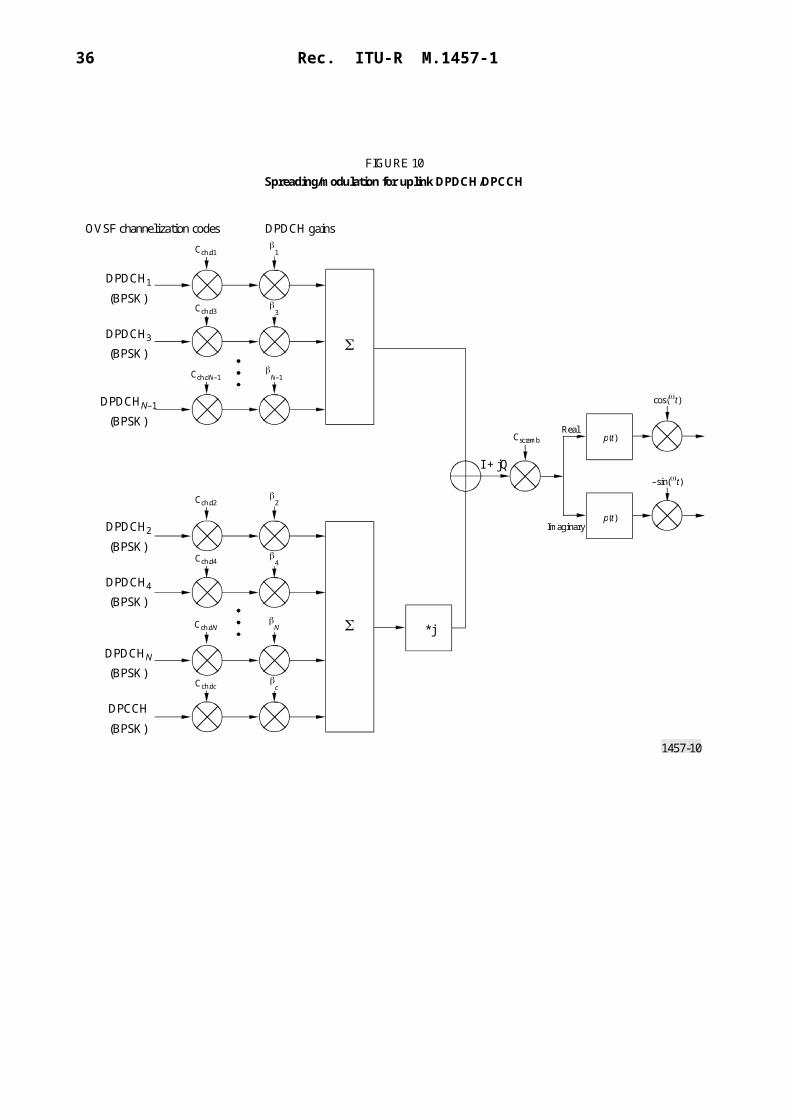
36 Rec. ITU-R M.1457-1
Document No. Version Status Issued date Location(1)
(2) ARIB ARIB STD-T-63-25.432 3.1.0 Approved by ARIB Standard Assembly
2000-03-31 http://www.arib.or.jp/IMT-2000/ARIB-STD/STD-T63/25.432.html
CWTS CWTS STD-DS-25.432 2000 Approved 2000-03 http://www.cwts.org/imt2000/DSETSI ETSI TS 125 432 3.1.0 ETSI published 2000-01 http://webapp.etsi.org/pda/
home.asp?wki_id=7767T1 T1TR3GPP 25.432 310 Approved 1999-10 https://www.atis.org/atis/docstore/
doc_display.asp?ID=599TTA TTAE.3G-25.432(F) 1 TA approved 2000-03-28 http://www.tta.or.kr/imt2000/STD-
DS/25432.zip
(1), (2) See Notes (1) and (2), § 5.1.2.1.1.

Rec. ITU-R M.1457-1 37
5.1.2.3.19 25.433 UTRAN Iub interface: NBAP signalling
This specification describes the standards for NBAP specification to be used over Iub interface.
5.1.2.3.20 25.434 UTRAN Iub interface data transport and transport signalling for common transport channel data streams
This specification describes the UTRAN RNC-Node B (Iub) interface data transport and transport signalling for CCH data streams.
5.1.2.3.21 25.435 UTRAN Iub interface user plane protocols for common transport channel data streams
This specification describes the UTRAN RNC-Node B (Iub) interface user plane protocols for common transport channel data streams.
Document No. Version Status Issued date Location(1)
(2) ARIB ARIB STD-T-63-25.433 3.0.0 Approved by ARIB Standard Assembly
2000-03-31 http://www.arib.or.jp/IMT-2000/ARIB-STD/STD-T63/25.433.html
CWTS CWTS STD-DS-25.433 2000 Approved 2000-03 http://www.cwts.org/imt2000/DSETSI ETSI TS 125 433 3.0.0 ETSI published 2000-01 http://webapp.etsi.org/pda/
home.asp?wki_id=7768T1 T1TR3GPP 25.433 320 Approved 2000-06 https://www.atis.org/atis/docstore/
doc_display.asp?ID=818TTA TTAE.3G-25.433(F) 1 TA approved 2000-03-28 http://www.tta.or.kr/imt2000/STD-
DS/25433.zip
(1), (2) See Notes (1) and (2), § 5.1.2.1.1.
Document No. Version Status Issued date Location(1)
(2) ARIB ARIB STD-T-63-25.434 3.1.0 Approved by ARIB Standard Assembly
2000-03-31 http://www.arib.or.jp/IMT-2000/ARIB-STD/STD-T63/25.434.html
CWTS CWTS STD-DS-25.434 2000 Approved 2000-03 http://www.cwts.org/imt2000/DSETSI ETSI TS 125 434 3.1.0 ETSI published 2000-01 http://webapp.etsi.org/pda/
home.asp?wki_id=7769T1 T1TR3GPP 25.434 310 Approved 1999-10 https://www.atis.org/atis/docstore/
doc_display.asp?ID=601TTA TTAE.3G-25.434(F) 1 TA approved 2000-03-28 http://www.tta.or.kr/imt2000/STD-
DS/25434.zip
(1), (2) See Notes (1) and (2), § 5.1.2.1.1.
Document No. Version Status Issued date Location(1)
(2) ARIB ARIB STD-T-63-25.435 3.1.0 Approved by ARIB Standard Assembly
2000-03-31 http://www.arib.or.jp/IMT-2000/ARIB-STD/STD-T63/25.435.html
CWTS CWTS STD-DS-25.435 2000 Approved 2000-03 http://www.cwts.org/imt2000/DSETSI ETSI TS 125 435 3.1.0 ETSI published 2000-01 http://webapp.etsi.org/pda/
home.asp?wki_id=7770T1 T1TR3GPP 25.435 330 Approved 2000-06 https://www.atis.org/atis/docstore/
doc_display.asp?ID=820TTA TTAE.3G-25.435(F) 1 TA approved 2000-03-28 http://www.tta.or.kr/imt2000/STD-
DS/25435.zip
(1), (2) See Notes (1) and (2), § 5.1.2.1.1.

38 Rec. ITU-R M.1457-1
5.1.2.3.22 25.442 UTRAN implementation specific O&M transport
This specification describes the transport of implementation specific O&M signalling between Node B and the management platform in case that the transport is routed via the RNC.
5.1.2.4 25.100 series
5.1.2.4.1 25.101 UE radio transmission and reception (FDD)
This specification describes the minimum RF characteristics of the FDD mode of UTRA.
5.1.2.4.2 25.133 Requirements for support of radio resource management (FDD)
This specification describes the requirements for support of radio resource management for FDD including requirements on measurements in UTRAN and the UE as well as on node dynamic behaviour and interaction, in terms of delay and response characteristics.
Document No. Version Status Issued date Location(1)
(2) ARIB ARIB STD-T-63-25.442 3.0.0 Approved by ARIB Standard Assembly
2000-03-31 http://www.arib.or.jp/IMT-2000/ARIB-STD/STD-T63/25.442.html
CWTS CWTS STD-DS-25.442 2000 Approved 2000-03 http://www.cwts.org/imt2000/DS
ETSI ETSI TS 125 442 3.0.0 ETSI published 2000-01 http://webapp.etsi.org/pda/home.asp?wki_id=8666
T1 T1TR3GPP 25.442 300 Approved 1999-10 https://www.atis.org/atis/docstore/doc_display.asp?ID=603
TTA TTAE.3G-25.442(F) 1 TA approved 2000-03-28 http://www.tta.or.kr/imt2000/STD-DS/25442.zip
(1), (2) See Notes (1) and (2), § 5.1.2.1.1.
Document No. Version Status Issued date Location(1)
(2) ARIB ARIB STD-T-63-25.101 3.1.0 Approved by ARIB Standard Assembly
2000-03-31 http://www.arib.or.jp/IMT-2000/ARIB-STD/STD-T63/25.101.html
CWTS CWTS STD-DS-25.101 2000 Approved 2000-03 http://www.cwts.org/imt2000/DS
ETSI ETSI TS 125 101 3.1.0 ETSI published 2000-01 http://webapp.etsi.org/pda/home.asp?wki_id=7771
T1 T1TR3GPP 25.101 331 Approved 2000-06 https://www.atis.org/atis/docstore/doc_display.asp?ID=777
TTA TTAE.3G-25.101(F) 1 TA approved 2000-03-28 http://www.tta.or.kr/imt2000/STD-DS/25101.zip
(1), (2) See Notes (1) and (2), § 5.1.2.1.1.
Document No. Version Status Issued date Location(1)
(2) ARIB ARIB STD-T-63-25.133 3.0.0 Approved by ARIB Standard Assembly
2000-03-31 http://www.arib.or.jp/IMT-2000/ARIB-STD/STD-T63/25.133.html
CWTS CWTS STD-DS-25.133 2000 Approved 2000-03 http://www.cwts.org/imt2000/DS
ETSI ETSI TS 125 133 3.0.0 ETSI published 2000-01 http://webapp.etsi.org/pda/home.asp?wki_id=9755
(1), (2) See Notes (1) and (2), § 5.1.2.1.1.

Rec. ITU-R M.1457-1 39
5.1.2.4.3 25.104 BTS radio transmission and reception (FDD)
This specification describes the base station minimum RF characteristics of the FDD mode of UTRA.
5.1.2.4.4 25.141 Base station conformance testing (FDD)
This specification describes the RF test methods and conformance requirements for UTRA base transceiver stations (BTS) operating in the FDD mode. These have been derived from, and are consistent with, the core UTRA specifications specified in the requirements reference subclause of each test.
5.1.2.4.5 25.113 Base station electromagnetic compatibility (EMC) (see Note 1)
This specification describes the assessment of base stations and associated ancillary equipment in respect of EMC.NOTE 1 – This specification does not include the antenna port immunity and emissions.
Document No. Version Status Issued date Location(1)
(2) ARIB ARIB STD-T-63-25.104 3.1.0 Approved by ARIB Standard Assembly
2000-03-31 http://www.arib.or.jp/IMT-2000/ARIB-STD/STD-T63/25.104.html
CWTS CWTS STD-DS-25.104 2000 Approved 2000-03 http://www.cwts.org/imt2000/DSETSI ETSI TS 125 104 3.1.0 ETSI published 2000-01 http://webapp.etsi.org/pda/
home.asp?wki_id=7772T1 T1TR3GPP 25.104 330 Approved 2000-06 https://www.atis.org/atis/docstore/
doc_display.asp?ID=779TTA TTAE.3G-25.104(F) 1 TA approved 2000-03-28 http://www.tta.or.kr/imt2000/STD-
DS/25104.zip
(1), (2) See Notes (1) and (2), § 5.1.2.1.1.
Document No. Version Status Issued date Location(1)
(2) ARIB ARIB STD-T-63-25.141 3.0.0 Approved by ARIB Standard Assembly
2000-03-31 http://www.arib.or.jp/IMT-2000/ARIB-STD/STD-T63/25.141.html
CWTS CWTS STD-DS-25.141 2000 Approved 2000-03 http://www.cwts.org/imt2000/DSETSI ETSI TS 125 141 3.0.0 ETSI published 2000-01 http://webapp.etsi.org/pda/
home.asp?wki_id=7776T1 T1TR3GPP 25.141 320 Approved 2000-06 https://www.atis.org/atis/docstore/
doc_display.asp?ID=783TTA TTAE.3G-25.141(F) 1 TA approved 2000-03-28 http://www.tta.or.kr/imt2000/STD-
DS/25141.zip
(1), (2) See Notes (1) and (2), § 5.1.2.1.1.
Document No. Version Status Issued date Location(1)
(2) ARIB ARIB STD-T-63-25.113 3.0.0 Approved by ARIB Standard Assembly
2000-03-31 http://www.arib.or.jp/IMT-2000/ARIB-STD/STD-T63/25.113.html
CWTS CWTS STD-DS-25.113 2000 Approved 2000-03 http://www.cwts.org/imt2000/DSETSI ETSI TS 125 113 3.0.0 ETSI published 2000-01 http://webapp.etsi.org/pda/
home.asp?wki_id=7778T1 T1TR3GPP 25.113 300 Approved 1999-12 https://www.atis.org/atis/docstore/
doc_display.asp?ID=676TTA TTAE.3G-25.113(F) 1 TA approved 2000-03-28 http://www.tta.or.kr/imt2000/STD-
DS/25113.zip
(1), (2) See Notes (1) and (2), § 5.1.2.1.1.

40 Rec. ITU-R M.1457-1
5.1.2.5 Core network aspects
5.1.2.5.1 23.108 Mobile radio interface Layer 3 specification core network protocols – Stage 2
This specification describes the procedures used at the radio interface for call control (CC), mobility management (MM) and session management (SM). It shall hold examples of the structured procedures.
5.1.2.5.2 23.110 UMTS access stratum services and functions
This specification describes the detailed specifications of the protocols which rule the information flows, both control and user data, between the access stratum and the parts of UMTS outside the access stratum, and of the detailed specifications of the UTRAN. These detailed specifications are to be found in other technical specifications.
5.1.2.5.3 24.007 Mobile radio interface signalling Layer 3 – general aspects
This specification describes the principal architecture of Layer 3 and its sublayers on the GSM Um interface, i.e. the interface between mobile station (MS) and network; for the CM sublayer, the description is restricted to paradigmatic examples, CC, supplementary services, and short message services for non-general packet radio service (GPRS) services. It also defines the basic message format and error handling applied by the Layer 3 protocols.
Document No. Version Status Issued date Location(1)
(2) TTC JP-3GA-23.108(R99) 1 TTC Technical Assembly approved
2000-03-31 http://www.ttc.or.jp/imt/std/jp23108r99.pdf
CWTS CWTS STD-DS-23.108 2000 Approved 2000-03 http://www.cwts.org/imt2000/DSETSI ETSI TS 123 108 3.1.0 ETSI published 2000-01 http://webapp.etsi.org/pda/
home.asp?wki_id=8661T1 T1TR3GPP 23.108 320 Approved 2000-03 https://www.atis.org/atis/docstore/
doc_display.asp?ID=768TTA TTAE.3G-23.108(F) 1 TA approved 2000-03-28 http://www.tta.or.kr/imt2000/STD-
DS/23108.zip
(1), (2) See Notes (1) and (2), § 5.1.2.1.1.
Document No. Version Status Issued date Location(1)
(2) TTC JP-3GA-23.110(R99) 1 TTC Technical Assembly approved
2000-03-31 http://www.ttc.or.jp/imt/std/jp23110r99.pdf
CWTS CWTS STD-DS-23.110 2000 Approved 2000-03 http://www.cwts.org/imt2000/DSETSI ETSI TS 123 110 3.3.0 ETSI published 2000-01 http://webapp.etsi.org/pda/
home.asp?wki_id=4358T1 T1TR3GPP 23.110 340 Approved 2000-03 https://www.atis.org/atis/docstore/
doc_display.asp?ID=769TTA TTAE.3G-23.110(F) 1 TA approved 2000-03-28 http://www.tta.or.kr/imt2000/STD-
DS/23110.zip
(1), (2) See Notes (1) and (2), § 5.1.2.1.1.

Rec. ITU-R M.1457-1 41
5.1.2.5.4 24.008 Mobile radio interface Layer 3 specification; core network protocols – Stage 3
This specification describes the procedures used at the radio interface for CC, MM and SM.
The procedures currently described are for the CC of circuit-switched connections, SM for GPRS services, MM and radio resource management for circuit-switched and GPRS services.
5.1.2.5.5 24.011 Point-to-point short message service (SMS) support on mobile radio interface
This specification describes the procedures used across the mobile radio interface by the signalling Layer 3 function short message control (SMC) and short message relay (SM-RL) function for both circuit-switched GSM and GPRS.
Document No. Version Status Issued date Location(1)
(2) TTC JP-3GA-24.007(R99) 1 TTC Technical Assembly approved
2000-03-31 http://www.ttc.or.jp/imt/std/jp24007r99.pdf
CWTS CWTS STD-DS-24.007 2000 Approved 2000-03 http://www.cwts.org/imt2000/DSETSI ETSI TS 124 007 3.2.0 ETSI published 2000-01 http://webapp.etsi.org/pda/
home.asp?wki_id=8775T1 T1TR3GPP 24.007 340 Approved 2000-06 https://www.atis.org/atis/docstore/
doc_display.asp?ID=771TTA TTAE.3G-24.007(F) 1 TA approved 2000-03-28 http://www.tta.or.kr/imt2000/STD-
DS/24007.zip(1), (2) See Notes (1) and (2), § 5.1.2.1.1.
Document No. Version Status Issued date Location(1)
(2) TTC JP-3GA-24.008(R99) 1 TTC Technical Assembly approved
2000-03-31 http://www.ttc.or.jp/imt/std/jp24008r99.pdf
CWTS CWTS STD-DS-24.008 2000 Approved 2000-03 http://www.cwts.org/imt2000/DSETSI ETSI TS 124 008 3.2.1 ETSI published 2000-01 http://webapp.etsi.org/pda/
home.asp?wki_id=7893T1 T1TR3GPP 24.008 341 Approved 2000-07 https://www.atis.org/atis/docstore/
doc_display.asp?ID=772TTA TTAE.3G-24.008(F) 1 TA approved 2000-03-28 http://www.tta.or.kr/imt2000/STD-
DS/24008.zip
(1), (2) See Notes (1) and (2), § 5.1.2.1.1.
Document No. Version Status Issued date Location(1)
(2) ARIB ARIB STD-T-63-24.011 3.1.0 Approved by ARIB Standard Assembly
2000-03-31 http://www.arib.or.jp/IMT-2000/ARIB-STD/STD-T63/24.011.html
CWTS CWTS STD-DS-24.011 2000 Approved 2000-03 http://www.cwts.org/imt2000/DS
ETSI ETSI TS 124 011 3.1.0 ETSI published 2000-01 http://webapp.etsi.org/pda/home.asp?wki_id=8776
T1 T1TR3GPP 24.011 330 Approved 2000-06 https://www.atis.org/atis/docstore/doc_display.asp?ID=774
TTA TTAE.3G-24.011(F) 1 TA approved 2000-03-28 http://www.tta.or.kr/imt2000/STD-DS/24011.zip
(1), (2) See Notes (1) and (2), § 5.1.2.1.1.

42 Rec. ITU-R M.1457-1
5.1.2.5.6 24.012 Short message service cell broadcast (SMSCB) support on the mobile radio interface
This specification describes how the SMSCB is supported over the mobile radio interface.
5.1.2.5.7 23.060 General packet radio service (GPRS) service description – Stage 2
This specification describes a general overview over the GPRS architecture as well as a more detailled overview of the MS – CN protocol architecture. Details of the protocols will be specified in companion documents.
5.1.2.5.8 24.022 Radio link protocol (RLP) for circuit switched bearer and teleservices
This specification describes the RLP for data transmission over the UMTS public land mobile network (PLMN). RLP covers the Layer 2 functionality of the ISO OSI reference model (IS 7498). It is based on ideas contained in IS 3309, IS 4335 and IS 7809 (HDLC of ISO) as well as ITU-T Recommendations X.25, Q.921 and Q.922 (LAP-B and LAP-D, respectively). RLP has been tailored to the special needs of digital radio transmission. RLP provides to its users the OSI data link service (IS 8886).
Document No. Version Status Issued date Location(1)
(2) ARIB ARIB STD-T-63-24.012 3.0.0 Approved by ARIB Standard Assembly
2000-03-31 http://www.arib.or.jp/IMT-2000/ARIB-STD/STD-T63/24.012.html
CWTS CWTS STD-DS-24.012 2000 Approved 2000-03 http://www.cwts.org/imt2000/DS
ETSI ETSI TS 124 012 3.0.0 ETSI published 2000-01 http://webapp.etsi.org/pda/home.asp?wki_id=9050
T1 T1TR3GPP 24.012 300 Approved 1999-10 https://www.atis.org/atis/docstore/doc_display.asp?ID=553
TTA TTAE.3G-24.012(F) 1 TA approved 2000-03-28 http://www.tta.or.kr/imt2000/STD-DS/24012.zip
(1), (2) See Notes (1) and (2), § 5.1.2.1.1.
Document No. Version Status Issued date Location(1)
(2) TTC JP-3GA-23.060(R99) 1 TTC Technical Assembly approved
2000-03-31 http://www.ttc.or.jp/imt/std/jp23060r99.pdf
CWTS CWTS STD-DS-23.060 2000 Approved 2000-03 http://www.cwts.org/imt2000/DS
ETSI ETSI TS 123 060 3.2.1 ETSI published 2000-01 http://webapp.etsi.org/pda/home.asp?wki_id=8769
T1 T1TR3GPP 23.060 340 Approved 2000-07 https://www.atis.org/atis/docstore/doc_display.asp?ID=766
TTA TTAE.3G-23.060(F) 1 TA approved 2000-03-28 http://www.tta.or.kr/imt2000/STD-DS/23060.zip
(1), (2) See Notes (1) and (2), § 5.1.2.1.1.

Rec. ITU-R M.1457-1 43
5.1.2.5.9 24.010 Mobile radio interface Layer 3 – supplementary services specification – general aspects
This specification describes the general aspects of the specification of supplementary services at the Layer 3 radio interface. Details will be specified in other documents.
5.1.2.5.10 24.080 Mobile radio interface Layer 3 – supplementary services specification – formats and coding
This specification describes the coding of information necessary for support of supplementary service operation on the mobile radio interface L3. Details will be specified in other documents.
Document No. Version Status Issued date Location(1)
CWTS CWTS STD-DS-24.022 2000 Approved 2000-03 http://www.cwts.org/imt2000/DS
ETSI ETSI TS 124 022 3.2.0 ETSI published 2000-01 http://webapp.etsi.org/pda/home.asp?wki_id=7896
T1 T1TR3GPP 24.022 330 Approved 2000-06 https://www.atis.org/atis/docstore/doc_display.asp?ID=775
TTA TTAE.3G-24.022(F) 1 TA approved 2000-03-28 http://www.tta.or.kr/imt2000/STD-DS/24022.zip
(1), (2) See Notes (1) and (2), § 5.1.2.1.1.
Document No. Version Status Issued date Location(1)
(2) TTC JP-3GA-20.010(R99) 1 TTC Technical Assembly approved
2000-03-31 http://www.ttc.or.jp/imt/std/jp24010r99.pdf
CWTS CWTS STD-DS-24.010 2000 Approved 2000-03 http://www.cwts.org/imt2000/DSETSI ETSI TS 124 010 3.0.0 ETSI published 2000-01 http://webapp.etsi.org/pda/
home.asp?wki_id=8664T1 T1TR3GPP 24.010 310 Approved 2000-06 https://www.atis.org/atis/docstore/
doc_display.asp?ID=773TTA TTAE.3G-24.010(F) 1 TA approved 2000-03-28 http://www.tta.or.kr/imt2000/STD-
DS/24010.zip
(1), (2) See Notes (1) and (2), § 5.1.2.1.1.
Document No. Version Status Issued date Location(1)
(2) TTC JP-3GA-24.080(R99) 1 TTC Technical Assembly approved
2000-03-31 http://www.ttc.or.jp/imt/std/jp24080r99.pdf
CWTS CWTS STD-DS-24.080 2000 Approved 2000-03 http://www.cwts.org/imt2000/DSETSI ETSI TS 124 080 3.1.0 ETSI published 2000-01 http://webapp.etsi.org/pda/
home.asp?wki_id=7903T1 T1TR3GPP 24.080 330 Approved 2000-06 https://www.atis.org/atis/docstore/
doc_display.asp?ID=776TTA TTAE.3G-24.080(F) 1 TA approved 2000-03-28 http://www.tta.or.kr/imt2000/STD-
DS/24080.zip
(1), (2) See Notes (1) and (2), § 5.1.2.1.1.

44 Rec. ITU-R M.1457-1
5.1.2.6 Terminal aspects
5.1.2.6.1 21.111 Universal subscriber identity module (USIM) and integrated circuit (IC) card requirements
This specification describes the requirements of the USIM and the USIM IC card (UICC). These are derived from the service and security requirements defined in the respective specifications. The document is the basis for the detailed specification of the USIM and the UICC, and the interface to the terminal.
5.1.2.6.2 23.038 Alphabets and language specific information
This specification describes the language specific requirements for the terminals including character coding.
5.1.2.6.3 23.040 Technical realization of SMS point-to-point
This specification describes the point-to-point SMS.
Document No. Version Status Issued date Location(1)
(2) ARIB ARIB STD-T-63-21.111 3.0.1 Approved by ARIB Standard Assembly
2000-03-31 http://www.arib.or.jp/IMT-2000/ARIB-STD/STD-T63/21.111.html
CWTS CWTS STD-DS-21.111 2000 Approved 2000-03 http://www.cwts.org/imt2000/DSETSI ETSI TS 121 111 3.0.1 ETSI published 2000-01 http://webapp.etsi.org/pda/
home.asp?wki_id=5817T1 T1TR3GPP 21.111 320 Approved 2000-07 https://www.atis.org/atis/docstore/
doc_display.asp?ID=741TTA TTAE.3G-21.111(F) 1 TA approved 2000-03-28 http://www.tta.or.kr/imt2000/STD-
DS/21111.zip(1), (2) See Notes (1) and (2), § 5.1.2.1.1.
Document No. Version Status Issued date Location(1)
(2) ARIB ARIB STD-T-63-23.038 3.3.0 Approved by ARIB Standard Assembly
2000-03-31 http://www.arib.or.jp/IMT-2000/ARIB-STD/STD-T63/23.038.html
CWTS CWTS STD-DS-23.038 2000 Approved 2000-03 http://www.cwts.org/imt2000/DSETSI ETSI TS 123 038 3.3.0 ETSI published 2000-01 http://webapp.etsi.org/pda/
home.asp?wki_id=8033T1 T1TR3GPP 23.038 330 Approved 2000-01 https://www.atis.org/atis/docstore/
doc_display.asp?ID=658TTA TTAE.3G-23.038(F) 1 TA approved 2000-03-28 http://www.tta.or.kr/imt2000/STD-
DS/23038.zip
(1), (2) See Notes (1) and (2), § 5.1.2.1.1.

Rec. ITU-R M.1457-1 45
Document No. Version Status Issued date Location(1)
(2) ARIB ARIB STD-T-63-23.040 3.3.0 Approved by ARIB Standard Assembly
2000-03-31 http://www.arib.or.jp/IMT-2000/ARIB-STD/STD-T63/23.040.html
CWTS CWTS STD-DS-23.040 2000 Approved 2000-03 http://www.cwts.org/imt2000/DSETSI ETSI TS 123 040 3.3.0 ETSI published 2000-01 http://webapp.etsi.org/pda/
home.asp?wki_id=8032T1 T1TR3GPP 23.040 350 Approved 2000-07 https://www.atis.org/atis/docstore/
doc_display.asp?ID=764TTA TTAE.3G-23.040(F) 1 TA approved 2000-03-28 http://www.tta.or.kr/imt2000/STD-
DS/23040.zip
(1), (2) See Notes (1) and (2), § 5.1.2.1.1.

46 Rec. ITU-R M.1457-1
5.1.2.6.4 23.041 Technical realization of cell broadcast service (CBS)
This specification describes the point-to-multipoint CBS.
5.1.2.6.5 23.042 Compression algorithm for text messaging services
This specification describes the compression algorithm for text messaging services.
5.1.2.6.6 27.005 Use of data terminal equipment – data circuit terminating equipment (DTE – DCE) interface for cell broadcast service (CBS)
This specification describes three interface protocols for control of SMS functions within a GSM mobile telephone from a remote terminal via an asynchronous interface.
Document No. Version Status Issued date Location(1)
(2) ARIB ARIB STD-T-63-23.041 3.1.0 Approved by ARIB Standard Assembly
2000-03-31 http://www.arib.or.jp/IMT-2000/ARIB-STD/STD-T63/23.041.html
CWTS CWTS STD-DS-23.041 2000 Approved 2000-03 http://www.cwts.org/imt2000/DS
ETSI ETSI TS 123 041 3.1.0 ETSI published 2000-01 http://webapp.etsi.org/pda/home.asp?wki_id=8781
T1 T1TR3GPP 23.041 320 Approved 2000-03 https://www.atis.org/atis/docstore/doc_display.asp?ID=765
TTA TTAE.3G-23.041(F) 1 TA approved 2000-03-28 http://www.tta.or.kr/imt2000/STD-DS/23041.zip
(1), (2) See Notes (1) and (2), § 5.1.2.1.1.
Document No. Version Status Issued date Location(1)
(2) ARIB ARIB STD-T-63-23.042 3.1.0 Approved by ARIB Standard Assembly
2000-03-31 http://www.arib.or.jp/IMT-2000/ARIB-STD/STD-T63/23.042.html
CWTS CWTS STD-DS-23.042 2000 Approved 2000-03 http://www.cwts.org/imt2000/DS
ETSI ETSI TS 123 042 3.1.0 ETSI published 2000-01 http://webapp.etsi.org/pda/home.asp?wki_id=8031
T1 T1TR3GPP 23.042 310 Approved 2000-01 https://www.atis.org/atis/docstore/doc_display.asp?ID=661
TTA TTAE.3G-23.042(F) 1 TA approved 2000-03-28 http://www.tta.or.kr/imt2000/STD-DS/23042.zip
(1), (2) See Notes (1) and (2), § 5.1.2.1.1.
Document No. Version Status Issued date Location(1)
(2) ARIB ARIB STD-T-63-27.005 3.1.0 Approved by ARIB Standard Assembly
2000-03-31 http://www.arib.or.jp/IMT-2000/ARIB-STD/STD-T63/27.005.html
CWTS CWTS STD-DS-27.005 2000 Approved 2000-03 http://www.cwts.org/imt2000/DSETSI ETSI TS 127 005 3.1.0 ETSI published 2000-01 http://webapp.etsi.org/pda/
home.asp?wki_id=8036T1 T1TR3GPP 27.005 310 Approved 2000-01 https://www.atis.org/atis/docstore/
doc_display.asp?ID=716TTA TTAE.3G-27.005(F) 1 TA approved 2000-03-28 http://www.tta.or.kr/imt2000/STD-
DS/27005.zip
(1), (2) See Notes (1) and (2), § 5.1.2.1.1.

Rec. ITU-R M.1457-1 47
5.1.2.6.7 27.007 AT command set for the user equipment (UE)
This specification describes a profile of AT commands and recommends that this profile be used for controlling mobile equipment (ME) functions and GSM network services from a terminal equip-ment (TE) through terminal adaptor (TA).
5.1.2.6.8 27.010 Terminal equipment to mobile station (TE to MS) multiplexer protocol
This specification describes a multiplexing protocol between a mobile station and an external data terminal for the purposes of enabling multiple channels to be established for different purposes (e.g. simultaneous SMS and data call).
5.1.2.6.9 27.103 Wide area network synchronization standard
This specification describes a definition of a wide area synchronization protocol. The synchron-ization protocol is based upon infrared mobile communication (IrMC) Level 4.
Document No. Version Status Issued date Location(1)
(2) ARIB ARIB STD-T-63-27.007 3.3.0 Approved by ARIB Standard Assembly
2000-03-31 http://www.arib.or.jp/IMT-2000/ARIB-STD/STD-T63/27.007.html
CWTS CWTS STD-DS-27.007 2000 Approved 2000-03 http://www.cwts.org/imt2000/DSETSI ETSI TS 127 007 3.3.0 ETSI published 2000-01 http://webapp.etsi.org/pda/
home.asp?wki_id=8037T1 T1TR3GPP 27.007 350 Approved 2000-07 https://www.atis.org/atis/docstore/
doc_display.asp?ID=824TTA TTAE.3G-27.007(F) 1 TA approved 2000-03-28 http://www.tta.or.kr/imt2000/STD-
DS/27007.zip
(1), (2) See Notes (1) and (2), § 5.1.2.1.1.
Document No. Version Status Issued date Location(1)
(2) ARIB ARIB STD-T-63-27.010 3.2.0 Approved by ARIB Standard Assembly
2000-03-31 http://www.arib.or.jp/IMT-2000/ARIB-STD/STD-T63/27.010.html
CWTS CWTS STD-DS-27.010 2000 Approved 2000-03 http://www.cwts.org/imt2000/DSETSI ETSI TS 127 010 3.2.0 ETSI published 2000-01 http://webapp.etsi.org/pda/
home.asp?wki_id=8038T1 T1TR3GPP 27.010 330 Approved 2000-03 https://www.atis.org/atis/docstore/
doc_display.asp?ID=825TTA TTAE.3G-27.010(F) 1 TA approved 2000-03-28 http://www.tta.or.kr/imt2000/STD-
DS/27010.zip
(1), (2) See Notes (1) and (2), § 5.1.2.1.1.
Document No. Version Status Issued date Location(1)
(2) ARIB ARIB STD-T-63-27.103 3.0.0 Approved by ARIB Standard Assembly
2000-03-31 http://www.arib.or.jp/IMT-2000/ARIB-STD/STD-T63/27.103.html
CWTS CWTS STD-DS-27.103 2000 Approved 2000-03 http://www.cwts.org/imt2000/DS
ETSI ETSI TS 127 103 3.0.0 ETSI published 2000-01 http://webapp.etsi.org/pda/home.asp?wki_id=8867
T1 T1TR3GPP 27.103 300 Approved 1999-10 https://www.atis.org/atis/docstore/doc_display.asp?ID=617
TTA TTAE.3G-27.103(F) 1 TA approved 2000-03-28 http://www.tta.or.kr/imt2000/STD-DS/27103.zip
(1), (2) See Notes (1) and (2), § 5.1.2.1.1.

48 Rec. ITU-R M.1457-1
5.1.2.7 System aspects
IMT-2000 CDMA Direct Spread specification also includes the following documents which are useful and related to this Recommendation.
5.1.2.7.1 TS 23.002 UMTS release 1999 network architecture
This specification describes the possible architectures of the mobile system.
5.1.2.7.2 TS 23.101 General UMTS architecture
This specification describes the basic physical and functional separation of UMTS. The content of this specification is limited to those features that are common to all UMTS networks independent of their origin. It identifies and names the reference points and functional groupings appearing at this level.
5.1.2.7.3 TS 23.107 QoS concept and architecture
This specification describes the framework for QoS in UMTS. The document shall be used as a living document which will cover all issues related QoS in UMTS.
5.1.2.7.4 TS 23.110 UMTS access stratum
This specification describes the services provided by the access stratum to the rest of the system. This document describes the main functions visible at the boundary between the access stratum and the rest of the system, it describes in general terms the information flows, both control and user data, over this boundary and relevant for the access stratum.
5.1.2.7.5 TS 23.121 Architectural requirements for release 1999
This specification describes architectural requirements for release 1999 related to the evolution of the GSM platform towards UMTS with the overall goal of fulfilling the UMTS service require-ments, support of roaming and support of new functionality, signalling systems and interfaces.
5.1.2.7.6 TR 23.930 Iu principles
This specification describes the requirements on the Iu and studies relevant principles to guide further standardization of the related interface(s).
5.1.2.7.7 TS 22.002 Bearer services supported by a GSM PLMN
This 3G specification describes a set of bearer services to be provided to 3G subscribers by a 3G network itself and in connection with other networks. This document is also be used as a reference for defining the corresponding required mobile network capabilities which are specified by means of the connection type concept.
5.1.2.7.8 TS 22.004 General on supplementary services
This specification describes a recommended set of supplementary services to the teleservices and bearer services which will be supported by a 3G network in connection with other networks as a basis for the definition of the network capabilities required.
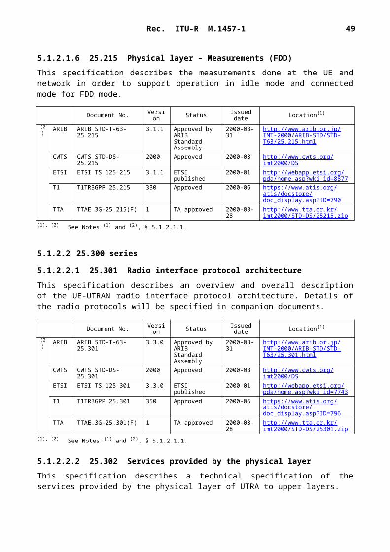
Rec. ITU-R M.1457-1 49
5.1.2.7.9 TS 22.011 Service accessibility
This specification describes the service access procedures as presented to the user. The document contains definitions and procedures are provided for international roaming, national roaming and regionally provided service. These are mandatory in relation to the technical realization of the UE.
5.1.2.7.10 TS 22.016 International mobile equipment identities (IMEI)
This specification describes the principal purpose and use of unique equipment identities.
5.1.2.7.11 TS 22.022 Personalization of GSM ME mobile functionality specification – Stage 1
This specification describes functional specifications of five features to personalize UE. These features are called:– network personalization;– network subset personalization;– service provider (SP) personalization;– corporate personalization;– UMTS subscriber identity module (USIM) personalization.
This specification describes requirements for UE, which provide these personalization features.
5.1.2.7.12 TS 22.024 Description of charge advice information (CAI)
This specification describes an overall view of how the charging advice supplementary service shall operate both in the network and within the UE. The charging supplementary service is described in TS 22.086.
5.1.2.7.13 TS 22.030 Man-machine interface (MMI) of the mobile station
This specification describes the requirements for and gives guidelines on the MMI for calls on the 3G UE. This includes the requirements of the user procedures for call control and supplementary service control, the requirements on the physical input media and the output, such as indications and displayed information.
5.1.2.7.14 TS 22.034 High speed circuit switched data (HSCSD) – Stage 1
This specification describes the Stage 1 description of HSCSD. HSCSD is a feature that allows users subscribing to the general bearer services to access user rates that can be achieved with one or more traffic channel. HSCSD also defines a flexible use of air interface resources, which makes efficient and flexible use of higher user rates feasible.
5.1.2.7.15 TS 22.038 SIM application toolkit (SAT) – Stage 1
This specification describes the Stage 1 description of the SAT primarily from the subscriber’s and serving environment’s points of view, and does not deal with the details of the human interface itself. It includes information applicable to network operators, serving environments and terminal, switch and database manufacturers and contains the core requirements for a SAT which are sufficient to provide a complete service.

50 Rec. ITU-R M.1457-1
5.1.2.7.16 TS 22.041 Operator determined call barring
The feature operator determined barring (ODB) allows the network operator or service provider to regulate, by means of an exceptional procedure, access by the subscribers to 3G services, by the barring of certain categories of outgoing or incoming calls or of roaming. ODB shall take effect immediately and shall terminate ongoing calls and bar future calls. The purpose of this network feature is to be able to limit the service provider’s financial exposure to new subscribers, or to those who have not promptly paid their bills. It may only be applied to the service provider’s own subscribers.
5.1.2.7.17 TS 22.042 Network identity and time zone (NITZ) – Stage 1
The feature NITZ provides the means for serving networks to transfer current identity, time, daylight saving time and the local time zone to user equipment storage and use.
5.1.2.7.18 TS 22.043 Support of localized service area (SoLSA) – Stage 1
This specification describes a mechanism, which can be used as a platform for providing special tariffs and/or special set of service features for certain subscribers within a regionally restricted area or areas. The motivation for this concept is to create means for network operators to build new service and tariff packages, which take into account subscriber groups and their needs.
5.1.2.7.19 TS 22.057 Mobile station application execution environment (MExE) – Stage 1
This specification describes the Stage 1 description of the MExE.
5.1.2.7.20 TS 22.060 General packet radio service (GPRS) – Stage 1
This specification describes the Stage 1 description of the GPRS.
5.1.2.7.21 TS 22.066 Support of mobile number portability (MNP) – Stage 1
This specification describes the Stage 1 description of the support of MNP between networks in the same country. It is in response to a study mandate agreed between the European Commission and ETSI under order voucher ETSI/97/M-251.
5.1.2.7.22 TS 22.067 Priority set-up service – Stage 1 (ASCI spec)
This specification describes the Stage 1 description of the enhanced multi-level precedence and pre-emption (eMLPP) service. This service has two parts: precedence and pre-emption. Precedence involves assigning a priority level to a call in combination with fast call set-up. Pre-emption involves the seizing of resources, which are in use by a call of a lower precedence, by a higher level precedence call in the absence of idle resources. Pre-emption can also involve the disconnection of an on-going call of lower precedence to accept an incoming call of higher precedence.
5.1.2.7.23 TS 22.071 Location services (LCS) – Stage 1
LCS is a network provided enabling technology consisting of standardized service capabilities which enables the provision of location applications. This application may be service provider

Rec. ITU-R M.1457-1 51
specific. The description of the numerous and varied possible location applications which are enabled by this technology are outside the scope of this specification. However, clarifying examples of how the functionality being specified may be used to provide specific LCS is included in various sections of the specification.
5.1.2.7.24 TS 22.072 Call deflection (CD) – Stage 1
CD enables the served mobile subscriber to respond to an incoming call offered by the network by requesting redirection of this call to another number specified in the response. The CD supplementary service can only be invoked before the connection is established by the served mobile subscriber, i.e. in response to the offered call, or during the period that the served subscriber is being informed of the call. The served subscriber’s ability to originate calls is unaffected by the CD supplementary service.
5.1.2.7.25 TS 22.078 Customized applications for mobile network enhanced logic (CAMEL) – Stage 1
This specification describes the Stage 1 description for CAMEL feature which provides the mechanisms to support services consistently independently of the serving network. The CAMEL features shall facilitate service control of operator specific services external from the serving network. The CAMEL feature is a network feature and not a supplementary service. It is a tool to help the network operator to provide the subscribers with the operator specific services even when roaming outside the home network.
5.1.2.7.26 TS 22.079 Support of optimal routing – Stage 1
Support of optimal routing is a network feature to reduce the number of unnecessary inter-network call legs when the subscriber is roaming.
5.1.2.7.27 TS 22.081 Line identification supplementary services – Stage 1
This specification describes the supplementary services belonging to the group line identification supplementary services. The group of line identification supplementary services is divided into the following four supplementary services:CLIP: calling line identification presentation (clause 1);CLIR: calling line identification restriction (clause 2);COLP: connected line identification presentation (clause 3);COLR: connected line identification restriction (clause 4).
5.1.2.7.28 TS 22.082 Call forwarding (CF) supplementary services – Stage 1
This specification describes the supplementary services belonging to the group call offering supplementary services.
The group of supplementary services call offering supplementary services is divided into four different supplementary services:– call forwarding unconditional (§ 1);– call forwarding on mobile subscriber busy (§ 2);– call forwarding on no reply (§ 3);– call forwarding on mobile subscriber not reachable (§ 4).

52 Rec. ITU-R M.1457-1
5.1.2.7.29 TS 22.083 Call waiting (CW) and call hold (HOLD) supplementary services – Stage 1
This specification describes the supplementary services belonging to the group call completion supplementary services which are divided into the following two supplementary services:– call waiting (clause 1);– call hold (clause 2).
5.1.2.7.30 TS 22.084 Multiparty (MPTY) supplementary service – Stage 1
This supplementary service provides a mobile subscriber with the ability to have a multi-connection call, i.e. a simultaneous communication with more than one party.
5.1.2.7.31 TS 22.085 Closed user group (CUG) supplementary services – Stage 1
The CUG supplementary service enables subscribers, connected to a network and possibly also other networks, to form CUGs to and from which access is restricted. A specific user may be a member of one or more CUGs. Members of a specific CUG can communicate among each other but not, in general, with users outside the group.
5.1.2.7.32 TS 22.086 Advice of charge (AoC) supplementary services – Stage 1
These services are designed to supply to a mobile user sufficient information to allow a real-time estimate to be made of the bill which will eventually be levied in the home public land mobile network (PLMN) on the mobile station subscriber.
5.1.2.7.33 TS 22.087 User-to-user signalling (UUS) – Stage 1
The UUS supplementary service allows a mobile subscriber to send/receive a limited amount of information to/from another network or ISDN subscriber over the signalling channel in association with a call to the other subscriber.
5.1.2.7.34 TS 22.088 Call barring (CB) supplementary services – Stage 1
The call restriction supplementary services allow the possibility for a mobile subscriber to have barring of certain categories of outgoing or incoming calls at the mobile subscribers access.
The group of call restriction services includes two supplementary services:– barring of outgoing calls;– barring of incoming calls.
By use of subscription options, the mobile subscriber can at provision time select a set of one or more barring programs to determine the categories of calls to be barred. The following categories are defined:– all outgoing calls;– outgoing international calls;– outgoing international calls except those directed to the home PLMN country;– all incoming calls;– incoming calls when roaming outside the home PLMN country.

Rec. ITU-R M.1457-1 53
5.1.2.7.35 TS 22.090 Unstructured supplementary service data (USSD) – Stage 1
There are two modes of USSD: MMI-mode and application mode. MMI-mode USSD is for the transparent transport of MMI strings entered by the user to the network and for the transparent transport of text strings from the network that are displayed by the mobile for user information.
Application mode USSD is for the transparent transport of data between the network and the mobile station. Application mode USSD is intended to be used by applications in the network and their peer applications in the UE.
The communication over the radio interface takes place on the signalling channels using short dialogues with peak data throughput rate capabilities of up to approximately 600 bits/s outside of a call and 1 000 bits/s during a call.
5.1.2.7.36 TS 22.091 Explicit call transfer (ECT) supplementary service – Stage 1
The ECT supplementary service enables the served mobile subscriber (subscriber A) who has two calls, each of which can be an incoming or outgoing call, to connect the other parties in the two calls and release the served mobile subscribers own connection.
5.1.2.7.37 TS 22.093 Call completion to busy subscriber (CCBS) – Stage 1
In the situation when subscriber A encounters a network determined user busy (NDUB) destination B, the subscriber A can request the CCBS supplementary service (i.e. activate a CCBS request against destination B). The network will then monitor the wanted destination B for becoming idle.
When the wanted destination B becomes idle, then the network will wait a short time in order to allow destination B to make an outgoing call. If destination B does not make any outgoing call within this time, then the network shall automatically recall subscriber A.
5.1.2.7.38 TS 22.096 Calling name presentation (CNAP) – Stage 1
The CNAP supplementary service enables the called party to receive the calling name information of the calling party.
5.1.2.7.39 TS 22.097 Multiple subscriber profile (MSP) – Stage 1
MSP is an optional service to enable mobile subscribers to have several profiles associated with a single subscriber identity (SIM) and a single international mobile subscriber identity (IMSI), with each profile being a subscription option. Each profile may be used for mobile originated and mobile terminated calls.
Up to four different profiles can be provisioned against a subscriber using the MSP feature. This will allow the subscriber to separate her telecommunication service needs into different identities (e.g. business and home).
5.1.2.7.40 TS 22.100 UMTS phase 1 capabilities
This specification describes contains how the definition of the UMTS system will be achieved in a phased approach. This document also specifies the requirements for release 99 of UMTS. Some requirements which are necessary to ensure a smooth transition to later releases are also indicated. This document should, however, be read in conjunction with the other 22.000 series documents which provide a complete description of the requirements for UMTS release 1999 and beyond.

54 Rec. ITU-R M.1457-1
5.1.2.7.41 TS 22.101 UMTS service principles
This specification describes the service principles of the UMTS.
5.1.2.7.42 TS 22.105 Services and service capabilities
Pre-UMTS systems have largely standardized the complete sets of bearer services, teleservices and supplementary services which they provide. One major difference between UMTS and pre-UMTS systems is that service capabilities rather than services are standardized for UMTS, allowing service differentiation and system continuity. This document describes how and what kind of services the UMTS user has access to.
5.1.2.7.43 TS 22.115 Service aspects: charging and billing
This specification describes the service aspects of charging and billing of the UMTS.
This standard is not intended to duplicate existing standards or standards being developed by other groups on these topics, and will reference these where appropriate. This standard will elaborate on the charging requirements described in the charging principles in TS 22.101 UMTS service principles. It will allow the generation of accurate charging information to be used in the commercial and contractual relationships between the parties concerned.
5.1.2.7.44 TS 22.121 Virtual home environment (VHE)
This specification describes the content of the Stage 1 requirement for realization of VHE. VHE is defined as a concept for personal service environment (PSE) portability across network boundaries and between terminals. The concept of the VHE is such that users are consistently presented with the same personalized features, user interface customization and services in whatever network and whatever terminal (within the capabilities of the terminal and the network), wherever the user may be located.
A key feature to support VHE is the ability to build services using a standardized application interface.
5.1.2.7.45 TS 22.129 Handover requirements between UMTS and GSM or other radio systems
This specification describes service requirements for handover (terms are defined below) within UMTS systems and between UMTS, other IMT-2000 family members and second generation systems. Particular emphasis has been placed on the description of requirements for handover between UMTS and GSM but requirements specific to other systems are incorporated as required.
5.1.2.7.46 TS 22.135 Multicall
This specification describes multicall scenarios and requirements for UMTS phase 1 release 1999.
Multicall feature specifies functionality and interactions related to usage of several simultaneous bearers between a terminal and a network. Multicall features allows both circuit-switched call(s) and packet session(s) to exist simultaneously.

Rec. ITU-R M.1457-1 55
5.1.2.7.47 TR 22.960 Mobile multimedia services including mobile Intranet and Internet services
This report describes the issues related to mobile multimedia in UMTS environment. Specifically the foreseen mobile multimedia applications and their special requirements are referred briefly. The major technical challenges faced in the provision of multimedia services and Internet and Intranet access are discussed and highlighted in order to give guidance for UMTS system standardization.
This text describes various views into these future topics and cannot be regarded as complete.
5.1.2.7.48 TR 22.971 Automatic establishment of roaming relations
This report describes a proposed framework for commercial and technical interworking between UMTS home environments and serving networks who have no direct prior commercial agreements with each other.
This text is applicable to UMTS standardization within ETSI, and is produced with the intent to clarify the concepts involved, and identify those areas which require standardization.
5.1.2.7.49 TR 22.975 Advanced addressing
This report describes the requirements for numbering and addressing for UMTS. This technical report is aimed at generating discussion and should be agreed with ETSI WG NA2. The respon-sibility for developing of numbering and addressing schemes for all networks being in ETSI NA2.
5.1.2.7.50 TS 21.133 Security threats and requirements
Detailed security requirements.
5.1.2.7.51 TS 33.102 Security architecture
Provides a specification of all security mechanisms and protocols, except algorithms.
5.1.2.7.52 TS 33.103 Security integration guidelines
5.1.2.7.53 TS 33.105 Cryptographic algorithm requirements
Defines requirements for standard cipher and integrity algorithm.
5.1.2.7.54 TS 33.106 Lawful interception requirements
Defines all requirements for network based lawful interception.
5.1.2.7.55 TS 33.120 Security objectives and principles
Elaborates on the basic principles underlying the security.
5.1.2.7.56 TR 33.901 Criteria for cryptographic algorithm design process
This report describes the process used to design cipher and integrity algorithm.
5.1.2.7.57 TR 33.902 Formal analysis of the 3G authentication protocol with modified sequence number management
Formal analysis using BAN and temporal logic of authentication mechanism.

56 Rec. ITU-R M.1457-1
5.1.2.7.58 TS 26.071 AMR speech codec: general description
This specification describes an introduction to the set of the adaptive multi-rate (AMR) specifications.
5.1.2.7.59 TS 26.090 AMR speech codec: transcoding functions
This specification describes a detailed description of the AMR speech codec transcoding functions.
5.1.2.7.60 TS 26.091 AMR speech codec: error concealment of lost frames
This specification describes example procedures for the error concealment, also called frame substitution or muting procedure, of lost speech or silence indicator frames.
5.1.2.7.61 TS 26.092 AMR speech codec: comfort noise aspects
This specification describes the detailed requirements for the correct operation of the background acoustic noise evaluation, noise parameter encoding/decoding and comfort noise generation for the AMR speech codec during source controlled rate (SCR) operation.
5.1.2.7.62 TS 26.093 AMR speech codec: source controlled rate (SCR) operation
This specification describes the operation of the AMR speech codec during SCR operation.
5.1.2.7.63 TS 26.094 AMR speech codec: voice activity detector (VAD)
This specification describes two alternatives for the VAD to be used during SCR operation in conjunction with the AMR codec.
5.1.2.7.64 TS 26.110 Codec for circuit-switched multimedia telephony service: general description
This specification describes an introduction to the set of specifications for the support of circuit-switched 3G-324M multimedia telephony service.
5.1.2.7.65 TS 26.111 Codec for circuit-switched multimedia telephony service: modifications to ITU-T Recommendation H.324
This specification describes the modifications applicable to the ITU-T Recommendation H.324, Annex C for the support of circuit-switched 3G-324M multimedia telephony service.
5.1.2.7.66 TR 26.911 Codec for circuit-switched multimedia telephony service: terminal implementor’s guide
This report describes non-mandatory Recommendations for the use of the different codec implementation options for the circuit-switched 3G-324M multimedia telephony service based on ITU-T Recommendation H.324, Annex C. These Recommendations address issues specific to the third generation operating environment, including guaranteeing sufficient error resilience and inter-working between terminals.

Rec. ITU-R M.1457-1 57
5.1.2.8 Vocabulary
Document 25.990 is a collection of terms, definitions and abbreviations related to the baseline documents defining the objectives and systems framework. This document provides a tool for further work on the technical documentation and facilitates their understanding.
5.1.2.9 SDO's complete system standard
5.2 IMT-2000 CDMA Multi-Carrier
5.2.1 Overview of the radio interface
5.2.1.1 Introduction
The IMT-2000 radio interface specifications for CDMA multi-carrier (MC) technology are developed by a partnership of SDOs (see Note 1). This radio interface is called cdma2000, which consists of the 1X and 3X components.NOTE 1 – Currently, these specifications are developed within the third generation partnership project 2 (3GPP2), where the participating SDOs are ARIB, CWTS, TIA, TTA and TTC.
In the development of this radio interface the CN specifications are based on an evolved ANSI-41, but the specifications include the necessary capabilities for operation with an evolved GSM-MAP-based CN.
This radio interface is a wideband spread spectrum radio interface that utilizes CDMA technology in order to meet the needs of the 3G wireless communication systems and to meet the requirements for the 3G evolution of the current 2G TIA/EIA-95-B family of standards.
Document No. Version Status Issued date Location(1)
(2) ARIB ARIB STD-T-12-25.990 3.0.0 Approved by ARIB Standard Assembly
2000-03-31 http://www.arib.or.jp/IMT-2000/ARIB-STD/STD-T12/25.990.html
CWTS CWTS STD-DS-25.990 2000 Approved 2000-03 http://www.cwts.org/imt2000/DS
ETSI ETSI TS 125 990 3.0.0 ETSI published 2000-01 http://webapp.etsi.org/pda/home.asp?wki_id=8667
T1 T1TR3GPP 25.990 300 Approved 1999-12 https://www.atis.org/atis/docstore/doc_display.asp?ID=604
TTA TTAE.3G-25.990(F) 1 TA approved 2000-03-28 http://www.tta.or.kr/imt2000/STD-DS/25990.zip
(1) The relevant SDOs should make their reference material available from their Web site.(2) This information was supplied by the recognized external organizations and relates to their own deliverables of the transposed
global core specification.
SDO Location
ARIB http://www.arib.or.jp/IMT-2000/ARIB-STD/STD-T63.htmlhttp://www.ttc.or.jp/e/imt
CWTS http://www.cwts.org/imt2000/DS
TTC http://www.ttc.or.jp/imt/std/
ETSI http://webapp.etsi.org/pda/(search string UMTS)
TTA http://www.tta.or.kr/

58 Rec. ITU-R M.1457-1
As shown in Fig. 13, the current TIA/EIA-95-B systems have a layered structure that provides voice, packet data (up to 64 kbit/s), simple circuit data (e.g. async fax), and simultaneous voice and packet data services. This radio interface provides protocols and services that correspond to the bottom two layers of the ISO/OSI reference model (i.e. Layer 1 – the physical layer, and Layer 2 – the link layer). Layer 2 is further subdivided into the link access control (LAC) sublayer and the MAC sublayer. Applications and upper layer protocols corresponding to OSI Layers 3 through 7 utilize the services provided by the LAC services, e.g. signalling services, voice services, data services (packet data and circuit data).
Motivated by higher bandwidths and the need to handle a wider variety of services, several enhancements have been incorporated in this radio interface (as highlighted in Fig. 13) and a generalized multimedia service model is supported. This allows any combination of voice, packet data, and high-speed circuit data services to be operated concurrently. The radio interface also includes a QoS control mechanism to balance the varying QoS requirements of multiple concurrent services (e.g. to support ISDN or RSVP network layer QoS capabilities).
The physical layer supports RF channel bandwidths of N 1.25 MHz, where N is the spreading rate number. Currently N 1 and 3 is specified, and N can be easily extended to N 6, 9, 12. The data rates, channel encoding, and modulation parameters supported on the traffic channels are specified by radio configurations. For Spreading rates 1 and 3, there are six radio configurations for the reverse link and there are nine radio configurations for the forward link. Collectively, these radio configurations form the radio interface, which consists of the 1X and 3X components. Spreading rate 1 corresponds to 1X. Spreading rate 3 corresponds to 3X. Radio configurations 1 and 2 are specified to be backward compatible with TIA/EIA-95-B systems. The radio interface also supports a class of operational band plans as specified in the TIA/EIA/IS-2000 standard.
1457-13
FIGURE 13General radio interface architecture
Upper layer signalling Data services Voiceservices
LACsublayer
RLP RLP RLP RLP
MACsublayer
Multiplexing and QoS delivery
Sign
allin
g to
phy
sica
l lay
er in
terf
ace
QQ Q Q
SRBP
CF
VoiceCF
CFRes
ourc
e co
ntro
l
MAC tosignallinginterface
(MACSIG)
Unique toIMT-2000
CDMA MC
OSILayers 3 to 7
OSILayer 2
OSILayer 1 Physical layer
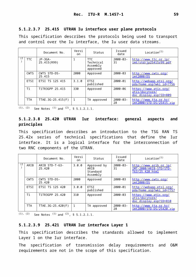
Rec. ITU-R M.1457-1 59
This specification includes a flexible and efficient MAC sublayer that supports multiple data service state machine instances, one for each active packet or circuit data service instance. Along with the multiplexing QoS control entity, the MAC realizes the complex multimedia, multi-service capabilities of 3G wireless systems with QoS management capabilities for each active service.
This specification also introduces a LAC sublayer to provide reliable transmission over the air for signalling services. To provide flexible voice services, this radio interface provides the framework and the services to transport encoded voice data in the form of packet data or circuit data traffic, as well as in a manner that is backward compatible with the TIA/EIA-95-B family of standards (i.e. the encoded voice data is transported directly by the physical layer). In the latter case, the LAC and MAC services are null. The LAC sublayer provides an ARQ (retransmission) protocol.
5.2.1.2 Physical layer
5.2.1.2.1 Reverse link (uplink)
Figure 14 shows the reverse CDMA channels received at the BS. The reverse pilot channel is an unmodulated spread spectrum signal used to assist the BS in detecting the mobile station transmission. The mobile station also inserts a reverse power control subchannel in the reverse pilot channel. The reverse power control subchannel is used to transmit forward power control commands. The access channel is used by the mobile station to initiate communication with the BS and to respond to paging channel messages. The enhanced access channel is used by the mobile station to initiate communication with the BS or to respond to a mobile station directed message. The reverse common control channel is used for the transmission of user and signalling information to the BS when reverse traffic channels are not in use. The reverse traffic channels with radio configurations 1 and 2 include the reverse fundamental channel and reverse supplemental code channel. The reverse traffic channels with radio configurations 3 through 6 include the reverse dedicated control channel, reverse fundamental channel, and reverse supplemental channel. The reverse dedicated control channel and reverse fundamental channel are used for the transmission of user and signalling information to the BS during a call. The reverse supplemental channel and reverse supplemental code channel are used for the transmission of user information to the BS during a call.
Figure 15 shows the reverse channel structure (except the pilot channel). Channel encoded symbols are repeated and punctured to match a nominal value of data rate. Block interleaving is used on the access channel, the enhanced access channel, the reverse common control channel, and the reverse traffic channels. The channel encoded and interleaved symbols are modulated and are direct spread prior to transmission. The spreading chip rate is N 1.2288 Mchip/s (N is the spreading rate number described above). Figure 16 shows the uplink spreading and the modulation operation for radio configurations 3 and above.
The mobile station supports three types of forward link power control based upon: 800 Hz feedback; the erasure indicator bits (EIB); and the quality indicator bits (QIB). The feedback is on the reverse power control subchannel. For the 800 Hz feedback mode, the outer loop estimates the

60 Rec. ITU-R M.1457-1
setpoint value based on Eb /Nt to achieve the target FER on each assigned forward traffic channel. The inner loop compares the Eb /Nt of the received forward traffic channel with the corresponding outer loop setpoint to determine the value of the power control bit to be sent on the reverse power control subchannel every 1.25 ms.
Uplink soft handoff is achieved by performing diversity or selection combining at the BS.
1457-14
FIGURE 14Reverse CDMA channels received at the BS
Reverse CDMA channel for spreading rate 1 and 3
Reversecommoncontrolchannel
operation
Reversetraffic
channeloperation
(RC 3 to 6)
Enhancedaccess
channeloperation
Reversetraffic
channel(RC 1 or 2)
Accesschannel
Reversepilot channel
Reversepilot channel
Reversefundamental
channel
Reversepilot channel
0 to 7 reversesupplemental
codes channels
Enhancedaccess
channel
Reversecommoncontrolchannel
0 or 1 reverse dedicatedcontrol channel
0 or 1 reversefundamental channel
0 to 2 reversesupplemental channels
Reverse powercontrol subchannel
1457-15
FIGURE 15Reverse channels structure (except the pilot channel)
Userbits
Add0 or 1
reservedbit
Addframequality
indicator
Add 8reserved/encodertail bits
Convolutionalor turboencoder
Symbolrepeti-
tion
Symbolpunc-ture
Blockinter-leaver
Modulationand
spreading

Rec. ITU-R M.1457-1 61
1457-16
Walsh cover(+ + – –) or (+ + – – – – + +)
Walsh cover(+ + + + + + + + – – – – – – – –)
Walsh cover(+ + + + – – – – + + + + – – – –)
Walsh cover(+ –) or (+ + – –)
for reverse supplemental channel 1(+ + – – + + – –)
for reverse common control channeland enhanced access channel
I-channelPN sequence
Q-channelPN sequence
Walsh cover(+ –)
Q-channeldata
I-channeldata
1-chipdelay
Long codegenerator
Decimatorby factor
of 2
Long codemask
Relativegain
Relativegain
Relativegain
RelativegainC
A
B
C
C
++
+
+
+
+
–
+
+
+
+
Gain
Basebandfilter
Basebandfilter
cos(2fct)
sin(2fct)
s(t)
Reversesupplemental
channel 1, reversecommon control
channel, or enhancedaccess channel
Reversefundamental
channel
Reversededicated
control channel
Reversepilot
channel
Reversesupplemental
channel 2
Complex multiplier
FIGURE 16Uplink spreading and modulation for radio configurations 3 and above
5.2.1.2.2 Forward link (downlink)
Figure 17 shows the forward CDMA channels received at the mobile station. The forward pilot channel, the transmit diversity pilot channel, the auxiliary pilot channels, and the auxiliary transmit diversity pilot channels are unmodulated spread spectrum signals used for synchronization by a mobile station operating within the coverage area of the BS. The forward pilot channel is transmitted at all times by the BS on each active forward CDMA channel. The auxiliary pilot

62 Rec. ITU-R M.1457-1
channel is transmitted in a beam forming application. The transmit diversity pilot channel and the auxiliary transmit diversity pilot channel are transmitted when transmit diversity is used. The sync

Rec. ITU-R M.1457-1 63
channel is used by mobile stations operating within the coverage area of the BS to acquire initial time synchronization. The paging channel is used by the BS to transmit system overhead information and mobile station specific messages. The broadcast channel is used by the BS to transmit system overhead information. The quick paging channel is used by the BS to inform mobile stations, operating in the slotted mode while in the idle state, whether or not to receive the forward common control channel, the broadcast channel, or the paging channel. The common power control channel is used by the BS for transmitting common power control subchannels (one bit per subchannel) for the power control of multiple reverse common control channels and enhanced access channels. The common power control subchannels are time multiplexed on the common power control channel. Each common power control subchannel controls a reverse common control channel or an enhanced access channel. The common assignment channel is used by the BS to provide quick assignment of the reverse common control channel. The forward common control channel is used by the BS to transmit mobile station-specific messages. For radio configurations 1 and 2, the forward traffic channels include the forward fundamental channel and forward supplemental code channel. For radio configurations 3 through 9, the forward traffic channels include the forward dedicated control channel, forward fundamental channel, and forward supplemental channel. Similar to the corresponding reverse traffic channels, these channels are used for transmission of user and/or signalling information to a specific mobile station during a call. The forward traffic channels also include the forward power control subchannel. It is used to transmit reverse power control commands and is transmitted either on the forward fundamental channel or on the forward dedicated control channel.
1457-17
Forward CDMA channel for spreading rates 1 and 3
FIGURE 17Forward CDMA channels received at the mobile station
Commonassignment
channels
Commonpower control
channels
Pilotchannels
Commoncontrol
channels
Syncchannel
Trafficchannels
Broadcastchannels
Pagingchannels
(SR1)
Quickpaging
channels
Auxiliary transmitdiversity pilot
channels
Auxiliarypilot
channels
Transmitdiversity
pilot channel
Forwardpilot
channel
0 to 2 supplementarychannels
(RC 3 to 9)
0 to 7 supplementarycode channels
(RC 1 or 2)
0 or 1 dedicatedcontrol channel
Power controlsubchannel
0 or 1fundamental
channel

64 Rec. ITU-R M.1457-1
The channel structure of the forward link is similar to that of the reverse link shown in Fig. 15, except that the sync channel and the paging channel do not use the frame quality indicator, and that the quick paging channel and the common power control channel do not use channel coding or interleaving. Block interleaving is used on the sync channel, the paging channels, the broadcast channel, the common assignment channel, the forward common control channel, and the forward traffic channels.
Figure 18 shows an example of scrambling, power control symbol puncturing, and demultiplexer structure for the forward traffic channels with radio configurations 3 and above. The channel encoded and interleaved output symbols are scrambled by the long code. The power control symbols are punctured on the forward fundamental channel and forward dedicated control channel only. The DEMUX functions distribute the scrambled and punctured symbols sequentially from the top to the bottom, forming pairs of quadrature modulation symbols. When operating in SR 1 (1X) without transmit diversity (TD), each modulation symbol in a quadrature pair is spread by the appropriate Walsh or quasi-orthogonal function and is then spread by a quadrature pair of PN sequences at a fixed chip rate of 1.2288 Mchip/s. When operating in SR 1 (1X) with transmit diversity, each modulation symbol in two quadrature pairs is spread by the appropriate Walsh or quasi-orthogonal function and a quadrature pair of PN sequences to a chip rate of 1.2288 Mchip/s. Then the two quadrature pairs are transmitted on two separate antennas. When operating in the SR N multi-carrier mode, each modulation symbol in N quadrature pairs is spread by the appropriate Walsh or quasi-orthogonal function and a quadrature pair of PN sequences to a chip rate of 1.2288 Mchip/s. Then the N quadrature pairs are transmitted on N adjacent 1.25 MHz carriers. Figure 19 shows the downlink spreading and modulation for SR 1 (1X) without transmit diversity as an example, which also shows each downlink modulation carrier for SR N multi-carrier operation. The system described in this sub-section can be deployed as an overlay on up to N carriers of TIA/EIA-95-B family of systems. This system can also be deployed in clear spectrum.
1457-18
YIYQX
X XYI1YI2YQ1YQ2
X
YI1YI2
YQ1YQ2
YI3
YQ3
+CModulationsymbol rate
FIGURE 18Example of scrambling, power control symbol puncturing and demultiplexing
Scrambling bitrepetition
Modulationsymbol rateEncoded
andinterleaved
symbol
Signal pointmapping
Channel gain
Powercontrol bits16 bits per
20 ms frameor 4 bits per5 ms frame
Forward powercontrol
subchannel gainI and Q scramblingbit extractor
Modulationsymbol rate
DecimatorLong codegenerator
Power control bitposition extractor
Powercontrolsymbol
puncture
Puncturetime
control(800 Hz)
Longcodemask
DEMUX
DEMUX
1. 1X non-TD
DEMUX
2. 1X TD
3. Multi-carrier 3X
a) Long code scrambling and power control symbol puncturing b) Demultiplexer structure

Rec. ITU-R M.1457-1 65
The reverse traffic channels utilize an 800 Hz feedback power control mechanism similar to that for the forward traffic channel. In addition, the mobile station supports open loop power control.
Downlink soft handoff is achieved by performing diversity combining at the mobile station. Transmit diversity is achieved by transmitting modulation symbols on separate transmit antennas or by transmitting separate carriers on separate antennas.
1457-19
+
–
+
+
+
+
Basebandfilter
Basebandfilter
cos(2fct)
sin(2fct)
s(t)
Complex multiplier
FIGURE 19Downlink spreading and modulation for 1X without transmit diversity
I
Q
Iin
Qin
PNI
PNQ
EnableWalshrot
YQ
QOFsign
Walshfunction
YI
Whenenabled,
rotateby 90°(output
–Qin+ jIin)
5.2.1.3 Layer 2 – MAC
5.2.1.3.1 Introduction
The MAC sublayer provides five important functions:– MAC control states – procedures for controlling the access of data services (packet and
circuit) to the physical layer (including contention control between multiple services from a single user, as well as between competing users within the wireless system).
– Best effort delivery – reasonably reliable transmission over the radio link with a RLP that provides a “best effort” level of reliability.
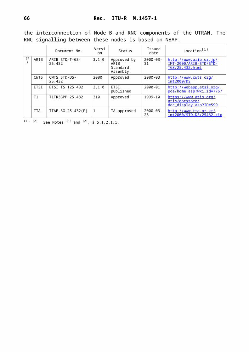
66 Rec. ITU-R M.1457-1
– Multiplexing and QoS control – enforcement of negotiated QoS levels by mediating conflicting requests from competing services and the appropriate prioritization of access requests.
– Short data burst – efficient transmission of small amount of packet data services bearer data on the common channels.
– Sophisticated reservation access – capabilities to provide efficient high-speed low latency common channel access.
The standard defines a resource configuration database (RCD), which is a data structure that captures all of the complexity of the advanced multimedia/multi-service operating modes supported by a mobile station. The database can be read from and can be written to by the BS so as to precisely control the operating configuration of the mobile station, including such attributes as the current logical-to-physical channel mapping assignments.
5.2.1.3.2 Layering structure and entities
The layering structure of this radio interface is composed of two separate planes: The control plane and the data plane. The principal advantage of this structuring is the clear definition of the service interfaces between all of the functional entities described by the layering structure. Figure 20 depicts the major functional blocks of the control and data planes.
The signalling control entity serves primarily as an agent to perform any required control plane operations on behalf of upper layer signalling. This includes performing required access operations on the RCD in order to satisfy upper layer signalling requests to read/write information from/to the RCD. Signalling control also transmits to upper layer signalling any indications of events within the control plane that are significant from a signalling perspective.
A dedicated/common router (DCR) supports the routing of data traffic to the RLP or the radio burst protocols (RBPs). The DCR physical layer independent control function (PLICF) entity for a data service instance provides the necessary configuration status information from resource control to DCR in order to determine whether LAC PDUs should be transmitted via RLP over DCH or should be transmitted via RBP on either a dedicated or common channel.
The voice PLICF entity performs the control plane functions required to support the voice protocol stack. The primary function of the voice PLICF is to request resources from the resource control entity, so as to satisfy the needs of voice services (e.g. to allocate a dedicated traffic channel), and to indirectly cause the allocation of physical layer resources on which this logical channel is carried.
The data service PLICF entity performs the control plane functions required to support data service operation whenever the data service option is connected.
The resource control entity acts as a central clearing-house for all resource requests on the mobile station (including both logical and physical channels). Resource control also maintains a database of all configuration information about the mobile station in the RCD. This configuration information is under direct control of the BS, which updates the database via upper layer signalling messages. Accesses to the database are performed on behalf of upper layer signalling by the signalling control entity.
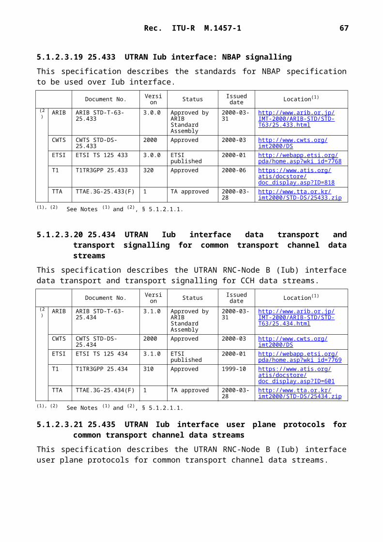
Rec. ITU-R M.1457-1 67
1457-20
(Vocoder)(Vocoder)
PPP
F/R-CCCH
F/R-FCH
F/R-DCCH
ACHPCH
F/R-SCH
f/r-dsch f/r-dtch f/r-dtchf/r-csch
Data planeControl plane
Upperlayer
signalling
Voice application(vocoder)Data application
SDBTS
Resourcecontrol
PLICFsublayer
DCR
Data LAC (or null)
Queuestatusand
control
DCRPLICF
TCP/UDPIP
PPPUserdata
Sign
allin
g to
phy
sica
l lay
er in
terf
ace
SignallingLAC
RLPqueue
Voice LAC(or null)
NullARQSRBP RLP
InstancespecificPLDCFsublayer
PLDCFand
Mux andQoS
sublayer
RBP
Signallingdata
Voice
Voice
Voice
Mux and QoS sublayer
Physical layercoding and modulation
Physicallayer
Mux andQoS
control
LACsublayer
Upperlayers
Signallingcontrol
FIGURE 20Layering structure and entities of the control plane and the data plane
VoicePLICF
DataservicePLICF
Res
ourc
eco
nfig
urat
ion
data
base
All resource requests to the resource control entity (from control plane PLICF entities) are made via a set of primitives based upon a two-stage model:– Request the logical resource that is to be allocated and initialized; and– Lock the resource for use by the requesting entity.
Because the association of logical-to-physical channels is not a simple one-to-one mapping, it is necessary to logically OR the logical channel requests from each of the active services, so as to arrive at a set of physical channels that are required for the currently active bearer service configuration. This function is accomplished by the resource control entity. Resource control

68 Rec. ITU-R M.1457-1
essentially merges the resource lock requests from all PLICF entities, and determines the minimal set of physical resources that are required to meet the needs. Resource control makes requests to upper layer signalling for any additional resources required from the BS.
When resource control determines that all resources requested by a PLICF have been secured, resource control sends lock confirmations to the appropriate PLICF entities. The PLICF entities may then complete any required state transitions based upon the confirmed resource availability. Resource control maintains an association in the RCD of all requesting entities to the actual logical and physical resources. Whenever a resource is unlocked by all PLICF entities, that resource can be released by resource control.
5.2.1.4 Layer 2 – LAC
The LAC sublayer performs the following important functions:– Delivery of SDUs to Layer 3 entity using ARQ techniques, when needed, to provide
reliability.– Building and validating well-formed PDUs appropriate for carrying the SDUs.– Segmentation of encapsulated PDUs into LAC PDU fragments of sizes suitable for transfer
by the MAC Sublayer and re-assembly of LAC PDU fragments into encapsulated PDUs.– Access control through global challenge authentication. Conceptually, some messages
failing authentication on a common channel should not be delivered to the upper layers for processing.
– Address control for delivery of PDUs based on addresses that identify particular mobile stations.
The general architecture is presented in two planes: A control plane, where processing decisions are made, and a data plane, where PDUs are generated, processed and transferred. The data plane contains the protocol, and is layered.
As a generated or received data unit traverses the protocol stack, it is processed by various protocol sublayers in sequence. Each sublayer processes only specific fields of the data unit that are associated with the sublayer-defined functionality. The general processing of data units by the LAC sublayer and its sublayers is shown in Fig. 21. The LAC sublayer provides services to Layer 3 in the data plane. SDUs are passed between Layer 3 and the LAC sublayer. The LAC sublayer provides the proper encapsulation of the SDUs into LAC PDUs, which are subject to segmentation and re-assembly and are transferred as LAC PDU fragments to the MAC sublayer.
In the data plane, Layer 3 and the LAC sublayer send and receive signalling information on logical channels, thus avoiding the need to be sensitive to the radio characteristics of the physical channels. The system described in this sub-section uses the following types of logical channel to carry signalling information:– f-csch/r-csch (forward and reverse common signalling channel, respectively),– f-dsch/r-dsch (forward and reverse dedicated signalling channel, respectively).
Logical channels are defined for the purposes of synchronization, broadcast, general signalling, access, and dedicated signalling. Multiple instances of the same logical channel may be deployed. Figures 22 and 23 show the logical channels on the forward and reverse links, respectively.

Rec. ITU-R M.1457-1 69
1457-21
Authentication,ARQ,
addressing
Utilitysublayer
SARsublayer
MAC sublayer
Physical layerLow
erla
yers
Layer 3
LAC
subl
ayer
L3 PDU
LAC SDU
LAC SDU
LAC SDU
LAC SDU CRCL
LAC PDU
Partially-formed LAC PDU
Encapsulated LAC PDU
LAC PDU fragments
MAC SDU
FIGURE 21LAC data unit processing
5.2.1.5 Layer 3 signalling
Layer 3 signalling provides a flexible structure designed to support a wide range of radio interface signalling alternatives:– backward compatible to TIA/EIA-95-B Layer 3 signalling;– the native upper layer signalling for this radio interface; and– other existing or future upper layer signalling entities.
In addition to supporting the standard cellular and PCS features, Layer 3 signalling also supports the following radio related features and capabilities:– Radio configuration negotiation– Quick paging operation (to improve battery life)– Handoff capabilities (i.e. soft handoff, hard handoff, idle handoff, access probe handoff,
and access handoff)– Power control– High-speed data– Enhance access– Broadcast control operation– Auxiliary pilot support, and– MAC state transitions.

70 Rec. ITU-R M.1457-1
1457-22
Utilitysublayer
Utilitysublayer
Utilitysublayer
SARsublayer
SARsublayer
SARsublayer
ARQsublayer
ARQsublayer
Addressingsublayer
Laye
r 3LA
C su
blay
erLa
yer 1
MA
Csu
blay
er
f-csch
Sync
cha
nnel
Bro
adca
st c
hann
el
Gen
eral
sign
allin
gch
anne
l
f-ds
ch
f-dt
ch
Physical channels
Signalling logicalchannels
User trafficlogical
channels
Common logicalchannels
Dedicatedlogical
channels
FIGURE 22Downlink logical channel architecture

Rec. ITU-R M.1457-1 71
1457-23
Utilitysublayer
Utilitysublayer
SARsublayer
SARsublayer
ARQsublayer
Laye
r 3LA
C su
blay
erLa
yer 1
MA
Csu
blay
er
r-cs
ch
f-ds
ch
f-dt
ch
Physicalchannels
Signalling logicalchannels
User trafficlogical
channels
Common logical
channels
Dedicatedlogical
channels
FIGURE 23Uplink logical channel architecture
Addressingsublayer
ARQsublayer
Authenticationsublayer

72 Rec. ITU-R M.1457-1
5.2.1.6 Summary of major technical parameters
5.2.2 Detailed specification of the radio interface
The standards contained in this section are derived from the global core specifications for IMT-2000 contained at http://ties.itu.int/u/itu-r/ede/rsg8/wp8f/rtech/GCS1457-0/.
5.2.2.1 cdma2000 specifications
The following six volumes provide cdma2000 1X and 3X radio interface specifications:– C.S0001-A Introduction to cdma2000 Standards for Spread Spectrum Systems– C.S0002-A Physical Layer Standard for cdma2000 Spread Spectrum Systems– C.S0003-A Medium Access Control (MAC) Standard for cdma2000 Spread Spectrum
Systems
Parameter Value Reference to § 5.2.2
Multiple access technique and duplexing scheme
Multiple access technique: CDMADuplexing scheme: FDD
5.2.2.3
Chip rate N 1.2288 Mchip/s (currently N 1 and 3 is specified, and N can be easily extended to N 6, 9, 12)
5.2.2.3
Inter-BS asynchronous/ synchronous operation
Synchronous operation is required 5.2.2.3
Pilot structure Code division dedicated pilot (UL); code division common pilot (DL); and code division common or dedicated auxiliary pilot (DL)
5.2.2.3
Frame length and interleaving
5, 10, 20, 40, 80 ms frame and channel interleaving 5.2.2.3
Modulation and detection Data modulation: BPSK; QPSKSpreading modulation: HPSK (UL); QPSK (DL)Detection: Pilot aided coherent detection
5.2.2.3
Channelization code Walsh codes and long codes (UL)Walsh codes or quasi-orthogonal codes (DL)
5.2.2.3
Scrambling (spreading) code
Long code and short PN code 5.2.2.3
Channel coding Convolutional code with K 9, R 1/2, 1/3, 1/4, or 1/6;Turbo code with K 4, R 1/2, 1/3, or 1/4
5.2.2.3
Access scheme (uplink) Basic access; power controlled access; reservation access; or designated access
5.2.2.3
Power control Open loopClosed loop (800 Hz or 50 Hz update rate)Power control steps: 1.0, 0.5, 0.25 dB
5.2.2.3

Rec. ITU-R M.1457-1 73
– C.S0004-A Signalling Link Access Control (LAC) Standard for cdma2000 Spread Spec-trum Systems
– C.S0005-A Upper Layer (Layer 3) Signalling Standard for cdma2000 Spread Spectrum Systems
– C.S0006-A Analog Standard for cdma2000 Spread Spectrum Systems.
In addition, the following two specifications support the OHG harmonization framework:– C.S0007 IMT-2000 CDMA-DS on ANSI-41– C.S0008 IMT-2000 CDMA-MC on GSM-MAP.
Other specifications, which are useful and related to IMT.RSPC, include:– N.S0005 Cellular Radiotelecommunications Intersystem Operations, December 1997– C.S0010 Recommended Minimum Performance Standards for Base Stations Supporting
Dual-Mode Spread Spectrum Mobile Stations, 1999– C.S0011 Recommended Minimum Performance Standards for Dual-Mode Spread Spec-
trum Mobile Stations, 1999– C.S0013 Mobile Station Loopback Service Options Standard, 1999– C.S0014 Enhanced Variable Rate Codec, Speech Service Option 3 for Wideband Spread
Spectrum Digital Cellular System, 1999– C.S0015 Short Message Services for Spread Spectrum Cellular Systems, 1999– C.S0016 Over-the-Air Service Provisioning of Mobile Stations in Spread Spectrum
Systems, June 1998– C.S0017 Data Services Standard for Wideband Spread Spectrum Systems, 1999– C.S0020 High Rate Speech Service Option for Wideband Spread Spectrum Communi-
cations Systems, 1999– N.S0010 Advanced Features in Wideband Spread Spectrum Systems, January 1998– C.P9000 Removable User Identity Module (R-UIM) for Spread Spectrum Systems, 1999– C.R1001 Administration of Parameter Value Assignments for TIA/EIA Spread Spectrum
Standards, 1999.
5.2.2.2 Introduction to cdma2000 standards for spread spectrum systems
This volume provides an overview of cdma2000 standards. The general architecture of cdma2000 and its relation to TIA/EIA-95-B family of standards is described. This volume also defines some common aspects such as channel naming convention used in the standard.
Document No. Version Status Issued date Location(1)
(2) ARIB ARIB STD-T64-C.S0001-A A Approved by ARIB Standard Assembly
2000-03-31 http://www.arib.or.jp/IMT-2000/ARIB-STD/STD-T64/C.S0001.html
CWTS CWTS STD-MC.S0001 A Approved 2000-03 http://www.cwts.org/imt2000/mc
TIA TIA/EIA/IS-2000.1-A Rev.A Published 2000-03-28 http://www.tiaonline.org/standards/sfg/imt2k/cdma2000
TTA TTAE.3G-C.S0001 1 TA approved 2000-03-28 http://www.tta.or.kr/imt2000/STD-MC/CS0001.zip
(1) The relevant SDOs should make their reference material available from their Web site.(2) This information was supplied by the recognized external organizations and relates to their own deliverables of the transposed
global core specification.

74 Rec. ITU-R M.1457-1
5.2.2.3 Physical layer standard for cdma2000 spread spectrum systems
This volume defines the physical layer of the cdma2000 standard, including the requirements for the mobile station and the BS CDMA operation. Section 1 defines the terms and numeric indications used in this document. This section also describes the time reference used in the CDMA system and the tolerances used throughout the document. Section 2 describes the physical layer requirements for mobile stations operating in the CDMA mode. Section 3 describes the require-ments for CDMA base stations.
5.2.2.4 Medium access control (MAC) standard for cdma2000 spread spectrum systems
This volume provides the detailed definitions of all component entities within the cdma2000 MAC layer, the service interfaces and primitives exchanged between entities within the MAC layer, and the service interfaces and primitives exchanged between the MAC layer and other cdma2000 layers. Section 1 contains the definitions of terms and an overview of this standard. Section 2 defines the normative behaviour of the cdma2000 MAC sublayer by describing the precise processing rules for each of the MAC sublayer entities. Section 3 describes the service interfaces between the MAC sublayer and other entities that are defined outside of this standards document (i.e. upper layer signalling and the physical layer). Section 4 contains a set of informative flow diagrams, which demonstrate the steps that the mobile station and the BS have to follow to make certain state transitions.
Document No. Version Status Issued date Location(1)
(2) ARIB ARIB STD-T64-C.S0002-A A Approved by ARIB Standard Assembly
2000-03-31 http://www.arib.or.jp/IMT-2000/ARIB-STD/STD-T64/C.S0002.html
CWTS CWTS STD-MC.S0002 A Approved 2000-03 http://www.cwts.org/imt2000/mc
TIA TIA/EIA/IS-2000.2-A Rev.A Published 2000-03-28 http://www.tiaonline.org/standards/sfg/imt2k/cdma2000
TTA TTAE.3G-C.S0002 1 TA approved 2000-03-28 http://www.tta.or.kr/imt2000/STD-MC/CS0002.zip
(1), (2) See Notes (1) and (2), § 5.2.2.2.
Document No. Version Status Issued date Location(1)
2) ARIB ARIB STD-T64-C.S0003-A
A Approved by ARIB Standard Assembly
2000-03-31 http://www.arib.or.jp/IMT-2000/ARIB-STD/STD-T64/C.S0003.html
CWTS CWTS STD-MC.S0003 A Approved 2000-03 http://www.cwts.org/imt2000/mc
TIA TIA/EIA/IS-2000.3-A Rev.A Published 2000-03-28 http://www.tiaonline.org/standards/sfg/imt2k/cdma2000
TTA TTAE.3G-C.S0003 1 TA approved 2000-03-28 http://www.tta.or.kr/imt2000/STD-MC/CS0003.zip
(1), (2) See Notes (1) and (2), § 5.2.2.2.

Rec. ITU-R M.1457-1 75
5.2.2.5 Signalling link access control (LAC) standard for cdma2000 spread spectrum systems
This volume describes the LAC signalling protocol architecture and functionality used to provide the transport and delivery of Layer 3 signalling messages over cdma2000 radio channels. Section 1 defines the terms and numeric information used in this standard. Section 2 describes the require-ments for cdma2000 mobile stations. Section 3 describes the requirements for cdma2000 BSs. Annex A describes the architectural and functional model used to develop cdma2000 LAC signalling. Annex B contains tables that give specific values for the constant identifiers found in Section 2 and Section 3.
5.2.2.6 Upper layer (Layer 3) signalling standard for cdma2000 spread spectrum systems
This volume details the Layer 3 call processing and procedures, including the requirements for the mobile station and the BS CDMA operation. Section 1 defines the terms and numeric indications used in this document. Section 2 defines requirements that are specific to CDMA mobile station equipment and operation. Section 3 defines requirements that are specific to CDMA BS equipment and operation.
5.2.2.7 Analogue standard for cdma2000 spread spectrum systems
This volume specifies analogue operation at 800 MHz based upon the standard TIA/EIA-553-A. This standard provides the differences within TIA/EIA-553-A, which are used by dual-mode mobile stations. Section 1 defines the terms and numeric indications used in this document. Section 2
Document No. Version Status Issued date Location(1)
(2) CWTS CWTS STD-MC.S0004 A Approved 2000-03 http://www.cwts.org/imt2000/mc
TTC JP-3GB-C.S0004-A 1 TTC Technical Assembly approved
2000-03-31 http://www.ttc.or.jp/imt/std/jpcs0004-a.pdf
TIA TIA/EIA/IS-2000.4-A Rev.A Published 2000-03-28 http://www.tiaonline.org/standards/sfg/imt2k/cdma2000
TTA TTAE.3G-C.S0004 1 TA approved 2000-03-28 http://www.tta.or.kr/imt2000/STD-MC/CS0004.zip
(1), (2) See Notes (1) and (2), § 5.2.2.2.
Document No. Version Status Issued date Location(1)
(2) CWTS CWTS STD-MC.S0005 A Approved 2000-03 http://www.cwts.org/imt2000/mc
TTC JP-3GB-C.S0005-A 1 TTC Technical Assembly approved
2000-03-31 http://www.ttc.or.jp/imt/std/jpcs0005-a.pdf
TIA TIA/EIA/IS-2000.5-A Rev.A Published 2000-03-28 http://www.tiaonline.org/standards/sfg/imt2k/cdma2000
TTA TTAE.3G-C.S0005 1 TA approved 2000-03-28 http://www.tta.or.kr/imt2000/STD-MC/CS0005.zip
(1), (2) See Notes (1) and (2), § 5.2.2.2.
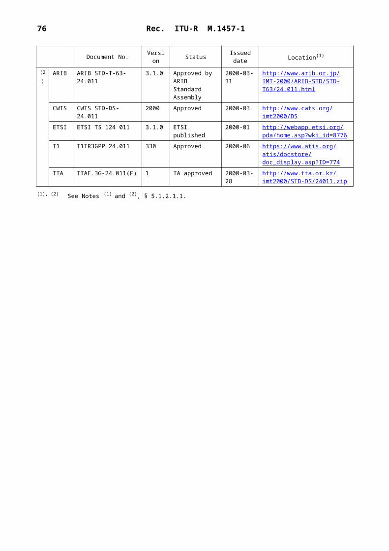
76 Rec. ITU-R M.1457-1
describes the requirements for CDMA-analogue dual-mode mobile stations operating in the analogue mode. Section 3 describes the requirements for analogue BSs. Section 4 describes the requirements for CDMA-analogue dual-mode mobile stations, which use the 32-digit dialling option on the reverse analogue control channel. In addition, this section describes mobile station requirements for use of the optional extended protocol. Section 5 describes the BS requirements for using the 32-digit dialling option on the reverse analogue control channel. In addition, this section describes BS requirements for use of the optional extended protocol.
5.2.2.8 IMT-2000 CDMA-DS on ANSI-41
This specification covers upper layers signalling protocols and procedures for the DS-41 (IMT-2000 CDMA-DS on ANSI-41) radio interface which support functionality customarily classified as pertaining to CC and MM.
5.2.2.9 IMT-2000 CDMA-MC on GSM-MAP
This specification covers lower layers (Layer 3 RRC, Layer 2, Layer 1) protocols and procedures for the MC-MAP (IMT-2000 CDMA-MC on GSM-MAP) radio interface.
Document No. Version Status Issued date Location(1)
(2) CWTS CWTS STD-MC.S0006 A Approved 2000-03 http://www.cwts.org/imt2000/mc
TIA TIA/EIA/IS-2000.6-A Rev.A Published 2000-03-28 http://www.tiaonline.org/standards/sfg/imt2k/cdma2000
TTA TTAE.3G-C.S0006 1 TA approved 2000-03-28 http://www.tta.or.kr/imt2000/STD-MC/CS0006.zip
(1), (2) See Notes (1) and (2), § 5.2.2.2.
Document No. Version Status Issued date Location(1)
(2) CWTS CWTS STD-MC.S0007 A Approved 2000-03 http://www.cwts.org/imt2000/mc
TTC JP-3GB-C.S0007 1 TTC Technical Assembly approved
2000-03-31 http://www.ttc.or.jp/imt/std/jpcs0007.pdf
TIA TIA/EIA/IS-834 Published 2000-03-28 http://www.tiaonline.org/standards/sfg/imt2k/cdma2000
TTA TTAE.3G-C.S0007 1 TA approved 2000-03-28 http://www.tta.or.kr/imt2000/STD-MC/CS0007.zip
(1), (2) See Notes (1) and (2), § 5.2.2.2.
Document No. Version Status Issued date Location(1)
(2) CWTS CWTS STD-MC.S0008 A Approved 2000-03 http://www.cwts.org/imt2000/mc
TTC JP-3GB-C.S0008 1 TTC Technical Assembly approved
2000-03-31 http://www.ttc.or.jp/imt/std/jpcs0008.pdf
TIA TIA/EIA/IS-833 Published 2000-03-28 http://www.tiaonline.org/standards/sfg/imt2k/cdma2000
TTA TTAE.3G-C.S0008 1 TA approved 2000-03-28 http://www.tta.or.kr/imt2000/STD-MC/CS0008.zip
(1), (2) See Notes (1) and (2), § 5.2.2.2.
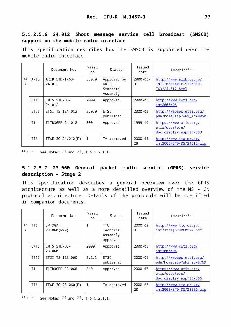
Rec. ITU-R M.1457-1 77
5.2.2.10 SDO's complete system standard
5.3 IMT-2000 CDMA TDD
5.3.1 Overview of the radio interface
5.3.1.1 Introduction
The IMT-2000 radio interface specifications for CDMA TDD technology are developed by a partnership of standards development organizations (SDOs) (see Note 1) and CWTS. This radio interface is called the universal terrestrial radio access (UTRA) time division duplex (TDD), and time division and space code multiple access (TD-SCDMA).
The UTRA TDD specifications have been developed with the strong objective of harmonization with the FDD component (see § 5.1) to achieve maximum commonality. This was achieved by harmonization of important parameters of the physical layer and a common set of protocols in the higher layers are specified for both FDD and TDD. The TD-SCDMA specifications were originally developed in China and introduced by CWTS. TD-SCDMA has significant commonality with UTRA TDD. Within the current specifications, capabilities are included to enable introduction of TD-SCDMA properties into a joint concept. The reference sections illustrate the current state of the specification processes (see Note 2).
In the development of this radio interface the core network specifications are based on an evolved GSM-MAP, but the specifications include the necessary capabilities for operation with an evolved ANSI-41-based core network.
The radio access scheme is direct-sequence code division multiple access. There are two chip rate versions: UTRA TDD with information spread over approximately 5 MHz bandwidth and a chip rate of 3.84 Mchip/s and TD-SCDMA with information spread over approximately 1.6 MHz bandwidth and a chip rate of 1.28 Mchip/s. The radio interface is defined to carry a wide range of services to efficiently support both circuit-switched services (e.g. PSTN- and ISDN-based networks) as well as packet-switched services (e.g. IP-based networks). A flexible radio protocol has been designed where several different services such as speech, data and multimedia can simultaneously be used by a user and multiplexed on a single carrier. The defined radio bearer services provide for both real-time and non-real-time services support by employing transparent and/or non-transparent data transport. The QoS can be adjusted in terms such as delay, BER and FER.NOTE 1 – Currently, these specifications are developed within the third generation partnership project (3GPP) where the participating SDOs are ARIB, CWTS, ETSI, T1, TTA and TTC.NOTE 2 – It is anticipated that following further harmonization initiatives a harmonized TDD solution will be developed in 3GPP.
SDO Location
ARIB/TTC http://www.arib.or.jp/IMT-2000/ARIB-STD/STD-T64.htmlhttp://www.ttc.or.jp/e/imt
CWTS http://www.cwts.org/imt2000/mcTTC http://www.ttc.or.jp/imt/std/TIA http://www.tiaonline.org/standards/sfg/imt2k/cdma2000TTA http://www.tta.or.kr/
78 Rec. ITU-R M.1457-1
5.3.1.2 Radio access network architecture
The overall architecture of the system is shown in Fig. 24.
The architecture of this radio interface consists of a set of radio network subsystems (RNS) connected to the core network through the Iu interface.
A RNS consists of a radio network controller (RNC) and one or more entities called Node B. The Node B is connected to the RNC through the Iub interface. Node B can handle one or more cells.
The RNC is responsible for the handover decisions that require signalling to the user equip-ment (UE).
Inside the radio interface, the RNCs of the RNS can be interconnected together through the Iur. The Iu and Iur are logical interfaces. Iur can be conveyed over physical direct connection between RNCs or via any suitable transport network.
Figure 25 shows the radio interface protocol architecture for the radio access network. On a general level, the protocol architecture is similar to the current ITU-R protocol architecture as described in Recommendation ITU-R M.1035. Layer 2 (L2) is split into two sublayers, RLC and MAC. Layer 3 (L3) and RLC are divided into Control (C-) and User (U-) planes.
In the C-plane, L3 is partitioned into sublayers where the lowest sublayer, denoted as RRC, interfaces with L2. The higher layer signalling such as MM and CC are assumed to belong to the core network. There are no L3 elements in UTRAN for the U-plane.
1457-24
FIGURE 24Radio access network architecture
(Cells are indicated by ellipses)
UE
RNC
Node B Node B Node B Node B
RNC
RNSRNS
Core network
Iu Iu
Iur
Iub Iub Iub Iub
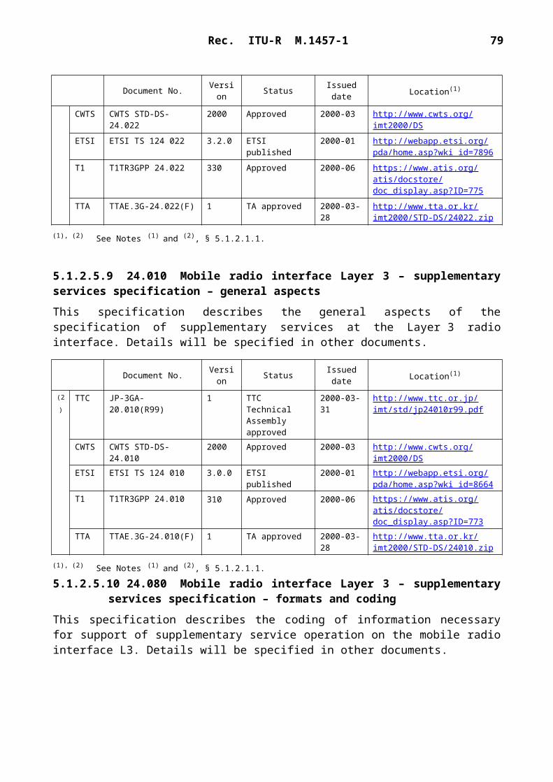
Rec. ITU-R M.1457-1 79
1457-25
FIGURE 25Radio interface protocol architecture of the RRC sublayer (L2 and L1)
RLCRLC
RLCRLC
RLCRLC
RLCRLC
RRCL3
GC Nt DC
C-plane signalling U-plane information
L2/RLC
L2/MAC
L1
Transportchannels
Logicalchannels
Physicalchannels
Con
trol
Con
trol
Con
trol
MAC
Physical
Each block in Fig. 25 represents an instance of the respective protocol. Service access points (SAPs) for peer-to-peer communication are marked with circles at the interface between sublayers. The SAPs between RLC and the MAC sublayer provide the logical channels. The type of information transferred characterizes a logical channel. The logical channels are divided into control channels and traffic channels. The different types are not further described in this overview. The SAP between MAC and the physical layer provides the transport channels. A transport channel is characterized by how the information is transferred over the radio interface, see § 5.3.1.3 for an overview of the types defined. The physical layer generates the physical channels that will be transmitted over the air. The physical channel is defined by carrier frequency, code, time slot and multi-frame information. In the C-plane, the interface between RRC and higher L3 sublayers (CC, MM) is defined by the GC, Nt and DC SAPs. These SAPs are not further discussed in this overview.
Also shown in the Figure are connections between RRC and MAC as well as RRC and L1 providing local inter-layer control services (including measurement results). An equivalent control interface exists between RRC and the RLC sublayer. These interfaces allow the RRC to control the configuration of the lower layers. For this purpose separate control SAPs are defined between RRC and each lower layer (RLC, MAC, and L1).
Figure 26 shows the general structure and some additional terminology definitions of the channel formats at the various sublayer interfaces indicated in Fig. 25. The Figure indicates how higher layer SDUs and PDUs are segmented and multiplexed to transport blocks to be further treated by the physical layer. The transmission chain of the physical layer is described in the next section.

80 Rec. ITU-R M.1457-1
1457
-26
Tran
spor
t blo
ck (M
AC
PD
U)
MA
Che
ader
CR
CC
RC
L1
MA
Che
ader
MA
C S
DU
MA
C S
DU
Tran
spor
t blo
ck (M
AC
PD
U)
L2 M
AC
(non
-tran
spar
ent)
RLC
head
erR
LChe
ader
L2 R
LC(n
on-tr
ansp
aren
t)R
LC S
DU
RLC
SD
U
Hig
her l
ayer
PD
UH
ighe
r lay
erH
ighe
r lay
erPD
U
Tim
e
Rea
ssem
bly
Segm
enta
tion
and
conc
aten
atio
n
FIG
UR
E 26
Dat
a flo
w fo
r a
serv
ice
usin
g a
non-
tran
spar
ent R
LC a
nd n
on-tr
ansp
aren
t MA
C(s
ee §
5.3
.1.4
.1 a
nd §
5.3
.1.4
.2 fo
r fu
rthe
r de
finiti
ons o
f the
MA
C a
nd R
LCse
rvic
es a
nd fu
nctio
nalit
y)

Rec. ITU-R M.1457-1 81
Opportunity driven multiple access (ODMA) operates on relay links between different relays. These relays may be represented by either UEs with ODMA capability or ODMA seeds (ODMA equipment permanently located in the network). Relays/seeds may act as gateways to connect the ODMA equipment to the radio interface. This can be done using either this radio interface or the radio interface in § 5.1.
5.3.1.3 Physical layer
5.3.1.3.1 UTRA TDD
5.3.1.3.1.1 Physical layer functionality and building blocks
The physical layer includes the following functionality:– Error detection on transport channels and indication to higher layers.– FEC encoding/decoding of transport channels.– Multiplexing of transport channels and demultiplexing of coded composite transport
channels.– Rate matching (data multiplexed on dedicated and shared channels).– Mapping of coded composite transport channels on physical channels.– Power weighting and combining of physical channels.– Modulation and spreading/demodulation and despreading of physical channels.– Frequency and time (chip, bit, slot, frame) synchronization.– Radio characteristics measurements including FER, S/I, interference power level etc., and
indication to higher layers.– Closed-loop power control.– RF processing.– Support of timing advance on uplink channels.
Figure 27 gives the physical layer transmission chain for the user plane data, i.e. from the level of transport channels down to the level of physical channel. The Figure shows how several transport channels can be multiplexed onto one or more DPDCH.
The CRC provides for error detection of the transport blocks for the particular transport channel. The CRC can take the length zero (no CRC), 8, 16 or 24 bits depending on the service requirements.
The transport block concatenation and code block segmentation functionality performs serial concatenation of those transport blocks that will be sent in one transport time interval and any code block segmentation if necessary.
The types of channel coding defined are convolutional coding, turbo coding and no coding. Real-time services use only FEC encoding while non-real-time services uses a combination of FEC and ARQ. The ARQ functionality resides in the RLC layer of Layer 2. The convolutional coding rates are 1/2 or 1/3 while the rate is 1/3 for turbo codes.
The possible interleaving depths are 10, 20, 40 or 80 ms.
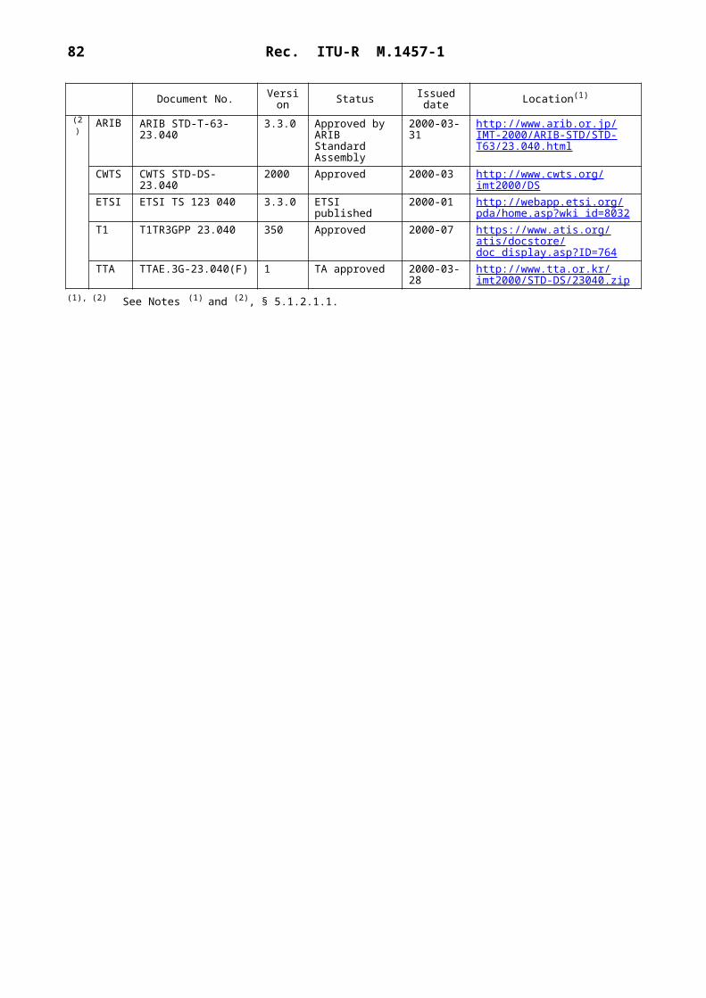
82 Rec. ITU-R M.1457-1
1457-27
CRC attachment
Transport block concatenationCode block segmentation
Channel coding
Radio frame equalization
1st interleaving
Radio frame segmentation
Rate matching
Transport channel (TrCH)multiplexing
Physical channelsegmentation
2nd interleaving
Physical channel mapping
DPC
H N
o. 2D
PCH
No. 1
FIGURE 27Transport channel multiplexing structure (UTRA TDD)

Rec. ITU-R M.1457-1 83
The radio frame segmentation performs padding of bits. The rate matching adapts any remaining differences of the bit rate so the number of outgoing bits fit to the available bit rates of the physical channels. Repetition coding and/or puncturing is used for this purpose.
The TrCH multiplexing stage combines transport channels in a serial fashion. This is done every 10 ms. The output of this operation is also called coded composite transport channels.
If several physical channels will be used to transmit the data, the split is made in the physical channel segmentation unit.
5.3.1.3.1.2 Transport channels
The interface to the MAC layer is the transport channels, see Fig. 25. The transport channels define how and with which type of characteristics the data is transferred by the physical layer. They are categorized into dedicated channels or common channels where many UEs are sharing the latter type. Introducing an information field containing the address then does the address resolution, if needed. The physical channel itself defines a dedicated channel. Thus no specific address is needed for the UE. Table 2 summarizes the different types of available transport channels.
TABLE 2
The defined transport channels
Transport channel Type and direction Used for
DCH (Dedicated channel) Dedicated; uplink and downlink
User or control information to a UE (entire cell or part of cell (lobe-forming))
BCH (Broadcast channel) Common; downlink Broadcast system and cell specific information
FACH (Forward access channel) Common; downlink Control information when system knows UE location or short user packets to a UE
PCH (Paging channel) Common; downlink Control information to UEs when good sleep mode properties are needed, e.g. idle mode operation
RACH (Random access channel)
Common; uplink Control information or short user packets from an UE
USCH (Uplink shared channel) Common; uplink TDD only. Carries dedicated user data and control information using a shared channel
ODCH (ODMA dedicated channel)
Dedicated TDD only. Applicable for ODMA relaying
ORACH (ODMA random access channel)
Common TDD only. Applicable for ODMA relaying
DSCH (Downlink shared channel)
Common; downlink Carries dedicated user data and control information using a shared channel.
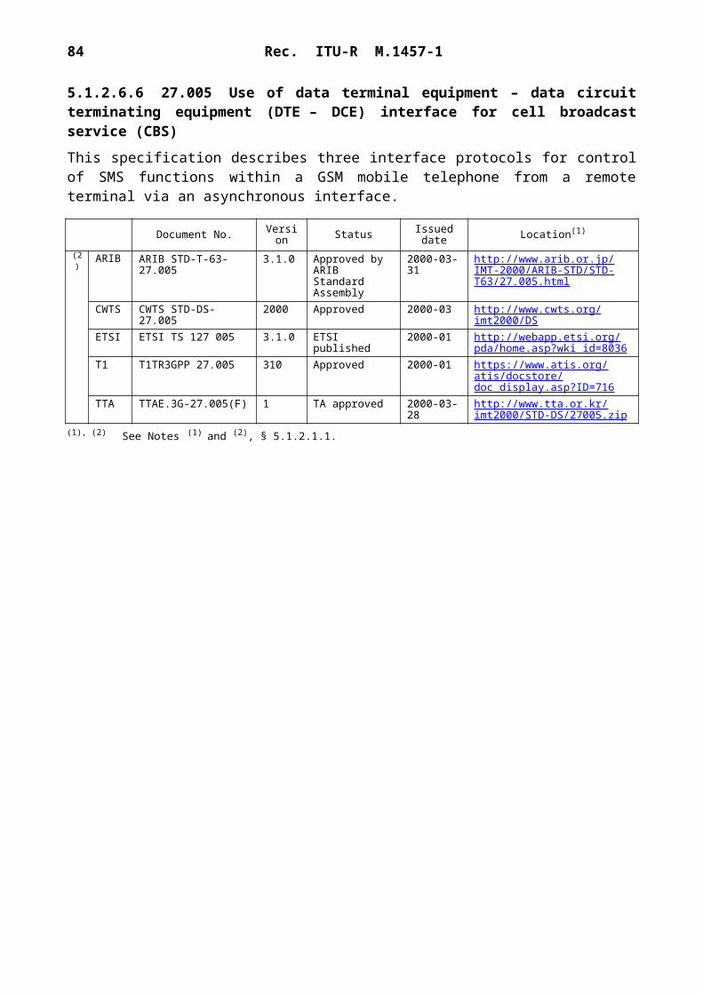
84 Rec. ITU-R M.1457-1
The RACH on the uplink is contention-based while the DCH is reservation-based.
5.3.1.3.1.3 Transport channels to physical channel mapping
The transport channels are mapped onto the physical channels and Fig. 28 shows the different physical channels and summarizes the mapping of transport channels onto physical channels. Each physical channel has its tailored slot content. The DCH is shown in § 5.3.1.3.1.4.
1457-28
Dedicated physical channel (DPCH)
Common control physical channel (CCPCH)
Physical random access channel (PRACH)
Physical synchronization channel (PSCH)
Physical uplink shared channel (PUSCH)
Physical downlink shared channel (PDSCH)
Page indicator channel (PICH)
DCHODCH*
BCHFACHPCH
RACHORACH*
SCH
USCH
DSCH
Transport channels Physical channels
FIGURE 28Transport channels, physical channels and their mapping
* In case of ODMA networks.
5.3.1.3.1.4 Physical frame structure
The basic physical frame rate is 10 ms with 15 slots. Figure 29 shows the frame structure.
1457-29
Timeslot No. 0
Super frame (720 ms)
Frame No. 0
FIGURE 29Basic frame structure - TDD
Frame No. 1 Frame No. 71
Timeslot No. 1 Timeslot No. 2 Timeslot No. 13 Timeslot No. 14
Timeslot (2 560 Tc)
Radio frame (10 ms)

Rec. ITU-R M.1457-1 85
Each 10 ms frame consists of 15 time slots, each allocated to either the uplink or the downlink. With such a flexibility, this radio interface can be adapted to different environments and deployment scenarios. In any configuration at least one time slot has to be allocated for the downlink and at least one time slot has to be allocated for the uplink.
When operating ODMA at least one common timeslot has to be allocated for the ORACH. If large quantities of information have to be transferred between ODMA nodes then it is normal to use at least one time slot for the ODCH (Fig. 30).
1457-30
ORACH slot
10 ms
FIGURE 30TDD frame structure example for ODMA operation
2 560 Tc
3.84
Mch
ip/s
ODCH slot
Relay link
Figures 31 and 32 show the two burst formats stating the content for a slot used by a DCH. The usage of either burst format 1 or 2 is depending on the application for UL or DL and the number of allocated users per time slot.
1457-31
Data symbols976 chips
FIGURE 31Burst structure of the burst type 1
(GP denotes the guard period and CP the chip periods)
2 560 Tc
Midamble512 chips
Data symbols976 chips
GP96CP
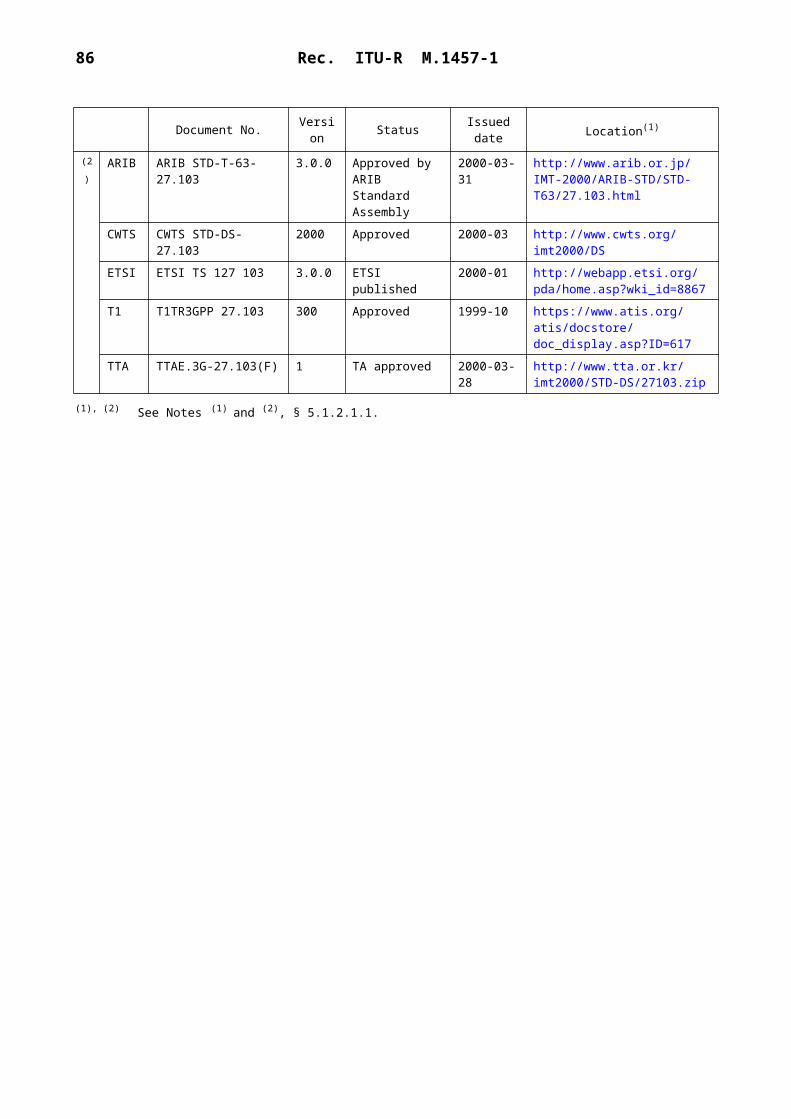
86 Rec. ITU-R M.1457-1
1457-32
Data symbols1 104 chips
FIGURE 32Burst structure of the burst type 2
(GP denotes the guard period and CP the chip periods)
2 560 Tc
Midamble256 chips
Data symbols1 104 chips
GP96CP
In both cases data bits are QPSK modulated and the resulting symbols are spread with a channelization code of length 1 to 16. Due to this variable spreading factor, each data part of one burst provides the number of symbols as shown in Table 3.
TABLE 3
Number of data symbols in TDD bursts
Thus, the number of bits per TDD burst is four times the number shown in Table 3. Usage of multicode and multiple time slots can be applied.
5.3.1.3.1.5 Spreading, modulation and pulse shaping
Spreading is applied after modulation and before pulse shaping. It consists of two operations. The first is the channelization operation, which transforms every data symbol into a number of chips, thus increasing the bandwidth of the signal. The number of chips per data symbol is called the spreading factor (SF) and is in the range of 1 to 16. The second operation is the scrambling operation, where a scrambling code is applied to the spread signal. This procedure is similar to the radio interface specified in § 5.1, but it should be noted that the midamble part in TDD bursts (see Figs. 31 and 32) is not spread.
The applied channelization codes are OVSF-codes that preserve the distinguishability of different users. The applied scrambling code is cell-specific and 128 different scrambling codes are available.
In the uplink, the applied midamble is user specific and derived from a cell-specific basic midamble sequence. In the downlink, the applied midamble is either user specific or common for the whole cell. In each case 128 different basic midamble sequences are available.
Spreading factor, Q Number of symbols, N, per data field in burst 1
Number of symbols, N, per data field in burst 2
1 976 1 1042 488 5524 244 2768 122 138
16 61 69

Rec. ITU-R M.1457-1 87
After spreading the same pulse-shaping is applied as in FDD mode, i.e. the filters are root-raised cosine with roll-off 0.22 in the frequency domain.
5.3.1.3.2 TD-SCDMA
5.3.1.3.2.1 Physical layer functionality and building blocks
The physical layer includes the following functionality:– FEC encoding/decoding of transport channels.– Macrodiversity distribution/combining and handover execution.– Multiplexing/demultiplexing of transport channels and of coded composite transport
channels.– Mapping of coded composite transport channels on physical channels.– Modulation and spreading/demodulation and despreading of physical channels.– Frequency and time (chip, bit, time slot, subframe) synchronization.– Power control.– Random access process.– Dynamic channel allocation (DCA).– ODMA specific procedures (optional).– Power weighting and combining of physical channels.– RF processing.– Error detection.– Rate matching (data multiplexed on DCH).– Radio characteristics measurements including FER, S/I, DOA, timing advance, etc.– Handover measurements.– Uplink synchronization.– Beamforming for both uplink and downlink (smart antenna).– UE location/positioning (smart antenna).
Figure 33 gives the physical layer transmission chain for the user plane data, i.e. from the level of transport channels down to the level of physical channel. Figure 33 shows how several transport channels can be multiplexed onto one or more dedicated physical channels (DPCH).
The CRC provides for error detection of the transport blocks for the particular transport channel. The CRC can take the length zero (no CRC), 8, 16 or 24 bits depending on the service requirements.
The transport block concatenation and code block segmentation functionality performs serial concatenation of those transport blocks that will be sent in one transport time interval and any code block segmentation if necessary.
The types of channel coding defined are convolutional coding, turbo coding and no coding. Real-time services use only FEC encoding while non-real-time services uses a combination of FEC and ARQ. The ARQ functionality resides in the RLC layer of Layer 2. The convolutional coding rates are 1/2 or 1/3 while the rate is 1/3 for turbo codes.

88 Rec. ITU-R M.1457-1
1457-33
CRC attachment
Transport block concatenationCode block segmentation
Channel coding
Radio frame equalization
1st interleaving
Radio frame segmentation
Rate matching
Transport channel (TrCH)multiplexing
Physical channelsegmentation
2nd interleaving
Physical channel mapping
DPD
CH
No. 2
DPD
CH
No. 1
FIGURE 33Transport channel multiplexing structure (TD-SCDMA)

Rec. ITU-R M.1457-1 89

90 Rec. ITU-R M.1457-1
The possible interleaving depths are 10, 20, 40 or 80 ms.
The radio frame equalization performs padding of bits. The rate matching adapts any remaining differences of the bit rate so the number of outgoing bits fit to the available bit rates of the physical channels. Repetition coding and/or puncturing is used for this purpose.
The TrCH multiplexing stage combines transport channels in a serial fashion. This is done every 10 ms. The output of this operation is also called coded composite transport channels.
If several physical channels will be used to transmit the data, the split is made in the physical channel segmentation unit.
5.3.1.3.2.2 Transport channels
The interface to the MAC layer is the transport channels, see Fig. 25. The transport channels define how and with which type of characteristics the data is transferred by the physical layer. They are categorized into DCH or common channels where many UEs are sharing the latter type. Introducing an information field containing the address then does the address resolution, if needed. The physical channel itself defines a DCH. Thus no specific address is needed for the UE. Table 4 summarizes the different types of available transport channels.
The RACH on the uplink is contention-based while the DCH is reservation-based.
5.3.1.3.2.3 Transport channels to physical channel mapping
The transport channels are mapped onto the physical channels and Fig. 34 shows the different physical channels and summarizes the mapping of transport channels onto physical channels. Each physical channel has its tailored slot content. The DCH is shown in § 5.3.1.3.2.4.
5.3.1.3.2.4 Frame structure
Physical channels take four-layer structure of super-frames, radio frames, sub-frames and time slots/codes as shown in Fig. 35. One super-frame has the length of 720 ms, which is composed by 72 radio frames. The radio frame has a duration of 10 ms and is subdivided into 2 sub-frames of 5 ms each, and each sub-frame is then subdivided into 7 main time slots of 675 s duration each and 3 special time slots: DwPTS (downlink pilot), G (guard period) and UpPTS (uplink pilot).
When operating ODMA at least one common timeslot has to be allocated for the ORACH. If large quantities of information have to be transferred between ODMA nodes then it is normal to use at least one time slot for the ODCH (see Fig. 36).
Rec. ITU-R M.1457-1 91
TABLE 4
The defined transport channels
Transport channel Type and direction Used for
DCH (dedicated channel) Dedicated; uplink and downlink
User or control information to a UE (entire cell or part of cell (lobe-forming))
BCH (broadcast channel) Common; downlink Broadcast system and cell specific information
FACH (forward access channel) Common; downlink Control information when system knows UE location or short user packets to a UE
PCH (paging channel) Common; downlink Control information to UEs when good sleep mode properties are needed, e.g. idle mode operation
RACH (random access channel) Common; uplink Control information or short user packets from an UE
SCH (pilot and synchronization channel)
Common; uplink and downlink
Transmit uplink/downlink pilot sequence and synchronization codes
ODCH(1) (ODMA dedicated channel)
Dedicated Applicable for ODMA relaying
ORACH(1) (ODMA random access channel)
Common Applicable for ODMA relaying
DSCH (downlink shared channel) Common; downlink Carries dedicated user data and control
information using a shared channel
USCH (uplink shared channel) Common; uplink Carries dedicated user data and control information using a shared channel
(1) Item which is an option.

92 Rec. ITU-R M.1457-1
1457-34
Dedicated physical channel (DPCH)
Common control physical channel (CCPCH)
Physical random access channel (PRACH)
Physical synchronization channel (PSCH)
DCHODCH*USCHDSCH
BCHFACHPCH
RACHORACH*
SCH
Transport channels Physical channels
FIGURE 34Transport channels, physical channels and their mapping
* Optional feature in TD-SCDMA
1457-35
Super-frame (720 ms)
Frame No. 0
FIGURE 35Frame and burst structure
Frame No. 1 Frame No. 71
Timeslot (675 s)
Radio frame (10 ms)
TimeslotDL No. n
Sub-frame No. 0 Sub-frame No. 1
Sub-frame (5 ms)
TimeslotDL No. 0
TimeslotUL No. 0
TimeslotUL No. m
where n + m + 2 = 7 DwPTS(75 s)
G(75 s)
UpPTS(125 s)
Rec. ITU-R M.1457-1 93
1457-36
ORACH slot
5 ms
FIGURE 36Frame structure for ODMA operation
ODCH slot
Relay link
1.28 Mchip/s
The burst structure is shown in Fig. 37. The burst type consist of two data symbol fields, a mid-amble of 144 chips and a guard period of 16 chips. The data fields of the burst type are 704 chips long. Data bits in the burst are QPSK modulated and are spread by the spreading factor of 1 to 16. The guard period for the burst type is 16 chips period long.
1457-37
675 s
FIGURE 37Burst struture
Data symbols352 chips
Data symbols352 chips
Midamble144 chips
GP16CP
The corresponding number of symbols depends on the spreading factor as indicated in Table 5.
TABLE 5
Number of data symbols in one burst with different SF
Spreading factor, Q Number of symbols, N, per data field in burst
1 3522 1764 888 44
16 22

94 Rec. ITU-R M.1457-1
5.3.1.3.2.5 Spreading, modulation and pulse shaping
Spreading is applied after modulation and before pulse shaping. It consists of two operations. The first is the channelization operation, which transforms every data symbol into a number of chips, thus increasing the bandwidth of the signal. The number of chips per data symbol is called the SF and is in the range of 1 to 16. The second operation is the scrambling operation, where a scrambling code is applied to the spread signal. It should be noted that the midamble part in TDD bursts is not spread.
The applied channelization codes are OVSF-codes that preserve the distinguishability of different users. The applied scrambling code is cell-specific.
In the uplink, the applied midamble is user specific and derived from a cell-specific basic midamble sequence. In the downlink, the applied midamble is either user specific or common for the whole cell.
After spreading, pulse-shaping is applied, i.e. the filters are root-raised cosine with roll-off 0.22 in the frequency domain.
5.3.1.3.2.6 Transmission and reception
The frequency bands assumed for operation are unpaired frequency bands at 2 GHz. Also the system can work in other frequency bands available. Several Tx power classes for UE are being defined currently.
5.3.1.4 Layer 2
5.3.1.4.1 MAC layer
The MAC sublayer is responsible for the handling of the data streams coming from the RLC and RRC sublayers. It provides an unacknowledged transfer mode service to the upper layers. The interface to the RLC sublayer is through logical channel service access points. It also re-allocates radio resources on request by the RRC sublayer as well as provides measurements to the upper layers. The logical channels are divided into control channels and traffic channels. Thus, the functionality handles issues like:– mapping of the different logical channels to the appropriate transport channels and selection
of appropriate transport format for the transport channels based on the instantaneous source bit rate. It also performs the multiplexing/ demultiplexing of the PDUs to/from transport blocks which are thereafter further treated by the physical layer;
– performs dynamic switching between common and dedicated transport channels based on information from the RRC sublayer;
– handles priority issues for services to one UE according to information from higher layers and physical layer (e.g. available transmit power level) as well as priority handling between UEs by means of dynamic scheduling in order to increase spectrum efficiency;
– monitor traffic volume that can be used by the RRC sublayer.
Figure 38 shows the possibilities of mapping the logical channel DTCH onto transport channels. There are possibilities to map onto shared transport channels as well as dedicated transport channels. The choice of mapping could be determined on e.g. amount of traffic a user creates.

Rec. ITU-R M.1457-1 95
1457-38
USCH RACH FACH DSCH DCH
DTCH-SAP
MAC SAP
FIGURE 38The possible channel mappings of the DTCH
(The arrows shows the direction of the channel (UE side);the directions are reversed from the network side)
Transportchannels
UE sideLogical channel
5.3.1.4.2 RLC sublayer
The RLC sublayer provides three different types of data transfer modes:– Transparent data transfer – This service transmits higher layer PDUs without adding any
protocol information, possibly including segmentation/reassemble functionality.– Unacknowledged data transfer – This service transmits higher layer PDUs without
guaranteeing delivery to the peer entity. The unacknowledged data transfer mode has the following characteristics:– Detection of erroneous data: The RLC sublayer shall deliver only those SDUs to the
receiving higher layer that are free of transmission errors by using the sequence-number check function.
– Unique delivery: The RLC sublayer shall deliver each SDU only once to the receiving upper layer using duplication detection function.
– Immediate delivery: The receiving RLC sublayer entity shall deliver a SDU to the higher layer receiving entity as soon as it arrives at the receiver.
– Acknowledged data transfer – This service transmits higher layer PDUs and guarantees delivery to the peer entity. In case RLC is unable to deliver the data correctly, the user of RLC at the transmitting side is notified. For this service, both in-sequence and out-of-sequence delivery are supported. In many cases a higher layer protocol can restore the order of its PDUs. As long as the out-of-sequence properties of the lower layer are known and controlled (i.e. the higher layer protocol will not immediately request retransmission of a missing PDU) allowing out-of-sequence delivery can save memory space in the receiving RLC. The acknowledged data transfer mode has the following characteristics:– Error-free delivery: Error-free delivery is ensured by means of retransmission. The
receiving RLC entity delivers only error-free SDUs to the higher layer.– Unique delivery: The RLC sublayer shall deliver each SDU only once to the receiving
upper layer using duplication detection function.– In-sequence delivery: RLC sublayer shall provide support for in-order delivery of
SDUs, i.e. RLC sublayer should deliver SDUs to the receiving higher layer entity in the same order as the transmitting higher layer entity submits them to the RLC sublayer.
96 Rec. ITU-R M.1457-1
– Out-of-sequence delivery: Alternatively to in-sequence delivery, it shall also be poss-ible to allow that the receiving RLC entity delivers SDUs to higher layer in different order than submitted to RLC sublayer at the transmitting side.
It also provides for RLC connection establishment/release. As well as QoS setting and notification to higher layers in case of unrecoverable errors.
An example of the data flow for non-transparent (acknowledged/unacknowledged) data transfer is shown in Fig. 26.
5.3.1.5 Layer 3 (radio resource control sublayer)
The radio resource control (RRC) sublayer handles the control plane signalling of Layer 3 between the UEs and the radio access network. In addition to the relation with the upper layers (such as core network) the following main functions are performed:– Broadcast of information provided by the non-access stratum (core network) – The RRC
layer performs system information broadcasting from the network to all UEs. The system information is normally repeated on a regular basis. This function supports broadcast of higher layer (above RRC) information. This information may be cell specific or not. As an example RRC may broadcast core network location service area information related to some specific cells.
– Broadcast of information related to the access stratum – The RRC layer performs system information broadcasting from the network to all UEs. This function supports broadcast of typically cell-specific information.
– Establishment, maintenance and release of an RRC connection between the UE and this radio interface – The establishment of an RRC connection is initiated by a request from higher layers at the UE side to establish the first signalling connection for the UE. The establishment of an RRC connection includes an optional cell re-selection, an admission control, and a Layer 2 signalling link establishment.
– Establishment, reconfiguration and release of radio access bearers – The RRC layer will, on request from higher layers, perform the establishment, reconfiguration and release of radio access bearers in the user plane. A number of radio access bearers can be established to an UE at the same time. At establishment and reconfiguration, the RRC layer performs admission control and selects parameters describing the radio access bearer processing in Layer 2 and Layer 1, based on information from higher layers.
– Assignment, reconfiguration and release of radio resources for the RRC connection – The RRC layer handles the assignment of radio resources (e.g. codes and, for TDD only, time slots) needed for the RRC connection including needs from both the control and user plane. The RRC layer may reconfigure radio resources during an established RRC connection. This function includes coordination of the radio resource allocation between multiple radio bearers related to the same RRC connection. RRC controls the radio resources in the uplink and downlink such that UE and the radio access network can communicate using unbalanced radio resources (asymmetric uplink and downlink). RRC signals to the UE to indicate resource allocations for purposes of handover to GSM or other radio systems.
Rec. ITU-R M.1457-1 97
– RRC connection mobility functions – The RRC layer performs evaluation, decision and execution related to RRC connection mobility during an established RRC connection, such as handover, preparation of handover to GSM or other systems, cell re-selection and cell/ paging area update procedures, based on e.g. measurements done by the UE.
– Paging/notification – The RRC layer can broadcast paging information from the network to selected UEs. The RRC layer can also initiate paging during an established RRC connection.
– Control of requested QoS – This function ensures that the QoS requested for the radio access bearers can be met. This includes the allocation of a sufficient number of radio resources.
– UE measurement reporting and control of the reporting – The measurements performed by the UE are controlled by the RRC layer, in terms of what to measure, when to measure and how to report, including both this radio interface and other systems. The RRC layer also performs the reporting of the measurements from the UE to the network.
– Outer loop power control (TD-SCDMA does not support this function.) – The RRC layer controls setting of the target of the closed-loop power control.
– Control of ciphering – The RRC layer provides procedures for setting of ciphering (on/off) between the UE and the radio access network.
– Initial cell selection and re-selection in idle mode – Selection of the most suitable cell based on idle mode measurements and cell selection criteria.
– Arbitration of the radio resource allocation between the cells – This function shall ensure optimal performance of the overall radio access network capacity.
– Broadcast of ODMA relay node neighbour information – The RRC layer performs probe information broadcasting to allow ODMA routeing information to be collected.
– Collating ODMA neighbour list and gradient information – The ODMA relay node neighbour lists and their respective gradient information maintained by the RRC.
– Maintenance of number of ODMA relay node neighbours – The RRC will adjust the broadcast powers used for probing messages to maintain the desired number of neighbours.
– Establishment, maintenance and release of a route between ODMA relay nodes – The establishment of an ODMA route and RRC connection based upon the routing algorithm.
– Interworking between the gateway ODMA relay node and the radio access network – The RRC layer will control the interworking communication link between the gateway ODMA relay node and the radio access network.
– Contention resolution – The RRC handles reallocations and releases of radio resources in case of collisions indicated by lower layers.
– Slow DCA – Allocation of preferred radio resources based on long-term decision criteria.– Timing advance control (TD-SCDMA does not support this function.) – The RRC controls
the operation of timing advance.– Active UE positioning (UTRA TDD does not support this function.) – This RRC layer will
determine the position of each active UE according to the received information from physical layer.

98 Rec. ITU-R M.1457-1
5.3.1.6 Summary of major technical parameters
5.3.2 Detailed specification of the radio interface
The standards contained in this section are derived from the global core specifications for IMT-2000 contained at http://ties.itu.int/u/itu-r/ede/rsg8/wp8f/rtech/GCS1457-0/.
5.3.2.1 25.200 series
5.3.2.1.1 25.201 Physical layer – General description
This specification describes the documents being produced by the TSG RAN WG 1. This specification gives also a general description of the physical layer of the UTRA radio interface.
Parameter Value Reference to § 5.3.2Multiple access technique and duplexing scheme
Multiple access: TDMA/CDMADuplexing: TDD
5.3.2.1.1
Chip rate (Mchip/s) 3.841.28
5.3.2.1.4
Frame length and structure Frame length: 10 ms15 slots per frame, each 666.666 sSub-frame length: 5 ms7 main slots per sub-frame, each 675 s
5.3.2.1.2
Occupied bandwidth (MHz) Less than 5Less than 1.6
5.3.2.4.15.3.2.4.3
Adjacent channel leakage power ratio (ACLR) (transmitter side)
UE (UE power class: 21 dBm)ACLR (5 MHz) 33 dBACLR (10 MHz) 43 dB
BS: ACLR (5 MHz) 45 dBACLR (10 MHz) 55 dB
UE (UE power class: 21 dBm)ACLR (1.6 MHz) 33 dBACLR (3.2 MHz) 43 dB
BS: ACLR (1.6 MHz) 40 dBACLR (3.2 MHz) 50 dB
5.3.2.4.1
5.3.2.4.3
Adjacent channel selectivity (ACS) (receiver side)
UE: ACS 33 dBBS: ACS 45 dB
5.3.2.4.15.3.2.4.3
Random access mechanism RACH burst on dedicated uplink slot(s) 5.3.2.1.2, 5.3.2.1.5Channel estimation Midambles are used for channel estimation 5.3.2.1.2Inter-base station asynchronous/ synchronous operation
Synchronous operation 5.3.2.1.55.3.2.4.3
Document No. Version Status Issued date Location(1)
(2) CWTS CWTS STD-TDD-101(3) 2000 Approved 2000-03 http://www.cwts.org/tdd
ETSI ETSI TS 125 201 3.0.1 ETSI published 2000-01 http://webapp.etsi.org/pda/home.asp?wki_id=7177
T1 T1TR3GPP 25.201 310 Approved 2000-06 https://www.atis.org/atis/docstore/doc_display.asp?ID=785
TTA TTAE.3G-25.201(T) 1 TA approved 2000-03-28 http://www.tta.or.kr/imt2000/STD-TDD/25201.zip
(1) The relevant SDOs should make their reference material available from their Web site.(2) This information was supplied by the recognized external organizations and relates to their own deliverables of the transposed
global core specification.(3) This specification gives also a general description of the physical layer of the TD-SCDMA air interface.

Rec. ITU-R M.1457-1 99
5.3.2.1.2 25.221 Physical channels and mapping of transport channels onto physical channels (TDD)
This specification describes the characteristics of the Layer 1 transport channels and physical channel in the TDD mode of UTRA. The main objectives of the document are to be a part of the full description of the UTRA Layer 1, and to serve as a basis for the drafting of the actual technical specification (TS).
5.3.2.1.3 25.222 Multiplexing and channel coding (TDD)
This specification describes multiplexing, channel coding and interleaving for UTRA physical layer TDD mode.
5.3.2.1.4 25.223 Spreading and modulation (TDD)
This specification describes the characteristics of the spreading and modulation in the TDD mode. The main objectives of the document are to be a part of the full description of the Layer 1, and to serve as a basis for the drafting of the actual technical specification (TS).
Document No. Version Status Issued date Location(1)
(2) CWTS CWTS STD-TDD-102(3) 2000 Approved 2000-03 http://www.cwts.org/tddETSI ETSI TS 125 221 3.1.1 ETSI published 2000-01 http://webapp.etsi.org/pda/
home.asp?wki_id=7738T1 T1TR3GPP 25.221 330 Approved 2000-06 https://www.atis.org/atis/docstore/
doc_display.asp?ID=791TTA TTAE.3G-25.221(T) 1 TA approved 2000-03-28 http://www.tta.or.kr/imt2000/STD-
TDD/25221.zip
(1), (2) See Notes (1) and (2), § 5.3.2.1.1.(3) This specification describes the characteristics of the Layer 1 transport channels and physical channel in the TD-SCDMA
radio system. The main objectives of the document are to be a part of the full description of the TD-SCDMA Layer 1, and to serve as a basis for the drafting of the actual technical specification (TS).
Document No. Version Status Issued date Location(1)
(2) CWTS CWTS STD-TDD-103(3) 2000 Approved 2000-03 http://www.cwts.org/tddETSI ETSI TS 125 222 3.1.1 ETSI published 2000-01 http://webapp.etsi.org/pda/
home.asp?wki_id=7739T1 T1TR3GPP 25.222 330 Approved 2000-06 https://www.atis.org/atis/docstore/
doc_display.asp?ID=792TTA TTAE.3G-25.222(T) 1 TA approved 2000-03-28 http://www.tta.or.kr/imt2000/STD-
TDD/25222.zip
(1), (2) See Notes (1) and (2), § 5.3.2.1.1.(3) This specification describes the characteristics of the Layer 1 multiplexing and channel coding in the TD-SCDMA.
Document No. Version Status Issued date Location(1)
(2) CWTS CWTS STD-TDD-104(3) 2000 Approved 2000-03 http://www.cwts.org/tddETSI ETSI TS 125 223 3.1.1 ETSI published 2000-01 http://webapp.etsi.org/pda/
home.asp?wki_id=7740T1 T1TR3GPP 25.223 330 Approved 2000-06 https://www.atis.org/atis/docstore/
doc_display.asp?ID=793TTA TTAE.3G-25.223(T) 1 TA approved 2000-03-28 http://www.tta.or.kr/imt2000/STD-
TDD/25223.zip
(1), (2) See Notes (1) and (2), § 5.3.2.1.1.(3) This specification describes spreading and modulation for the TD-SCDMA.

100 Rec. ITU-R M.1457-1
5.3.2.1.5 25.224 Physical layer procedures (TDD)
This specification describes the physical layer procedures in the TDD mode of UTRA.
5.3.2.1.6 25.225 Physical layer – Measurements (TDD)
This specification describes the description of the measurements done at the UE and network in order to support operation in idle mode and connected mode for TDD mode.
5.3.2.2 25.300 series
5.3.2.2.1 25.301 Radio interface protocol architecture
This specification describes an overview and overall description of the UE-UTRAN radio interface protocol architecture. Details of the radio protocols will be specified in companion documents.
Document No. Version Status Issued date Location(1)
(2) CWTS CWTS STD-TDD-105(3) 2000 Approved 2000-03 http://www.cwts.org/tdd
ETSI ETSI TS 125 224 3.1.1 ETSI published 2000-01 http://webapp.etsi.org/pda/home.asp?wki_id=7741
T1 T1TR3GPP 25.224 330 Approved 2000-06 https://www.atis.org/atis/docstore/doc_display.asp?ID=794
TTA TTAE.3G-25.224(T) 1 TA approved 2000-03-28 http://www.tta.or.kr/imt2000/STD-TDD/25224.zip
(1), (2) See Notes (1) and (2), § 5.3.2.1.1.(3) This specification describes and establishes the characteristics of the physical layer procedures in the TD-SCDMA.
Document No. Version Status Issued date Location(1)
(2) CWTS CWTS STD-TDD-106(3) 2000 Approved 2000-03 http://www.cwts.org/tdd
ETSI ETSI TS 125 225 3.1.1 ETSI published 2000-01 http://webapp.etsi.org/pda/home.asp?wki_id=8878
T1 T1TR3GPP 25.225 330 Approved 2000-06 https://www.atis.org/atis/docstore/doc_display.asp?ID=795
TTA TTAE.3G-25.225(T) 1 TA approved 2000-03-28 http://www.tta.or.kr/imt2000/STD-TDD/25225.zip
(1), (2) See Notes (1) and (2), § 5.3.2.1.1.(3) This specification describes the measurements done at the UE and network in order to support operation in idle mode and
connected mode.
Document No. Version Status Issued date Location(1)
(2) CWTS CWTS STD-TDD-001(3) 2000 Approved 2000-03 http://www.cwts.org/tdd
ETSI ETSI TS 125 301 3.3.0 ETSI published 2000-01 http://webapp.etsi.org/pda/home.asp?wki_id=7743
T1TR3GPP 25.301 350 Approved 2000-06 https://www.atis.org/atis/docstore/doc_display.asp?ID=796
TTA TTAE.3G-25.301(T) 1 TA approved 2000-03-28 http://www.tta.or.kr/imt2000/STD-TDD/25301.zip
(1), (2) See Notes (1) and (2), § 5.3.2.1.1.(3) This specification describes an overview description of the TD-SCDMA radio interface protocol architecture.

Rec. ITU-R M.1457-1 101
5.3.2.2.2 25.302 Services provided by the physical layer
This specification describes a technical specification of the services provided by the physical layer of UTRA to upper layers.
5.3.2.2.3 25.303 Interlayer procedures in connected mode
This specification describes informative interlayer procedures to perform the required tasks.
This specification attempts to provide a comprehensive overview of the different states and transitions within the connected mode of a UMTS terminal.
5.3.2.2.4 25.304 UE procedures in idle mode and procedures for cell reselection in connected mode
This specification describes the overall idle mode process for the UE and the functional division between the non-access stratum and access stratum in the UE. The UE is in idle mode when the connection of the UE is closed on all layers, e.g. there is neither an MM connection nor an RRC connection.
Document No. Version Status Issued date Location(1)
(2) CWTS CWTS STD-TDD-002(3) 2000 Approved 2000-03 http://www.cwts.org/tdd
ETSI ETSI TS 125 302 3.3.0 ETSI published 2000-01 http://webapp.etsi.org/pda/home.asp?wki_id=7744
T1 T1TR3GPP 25.302 350 Approved 2000-06 https://www.atis.org/atis/docstore/doc_display.asp?ID=797
TTA TTAE.3G-25.302(T) 1 TA approved 2000-03-28 http://www.tta.or.kr/imt2000/STD-TDD/25302.zip
(1), (2) See Notes (1) and (2), § 5.3.2.1.1.(3) This specification describes a technical specification of the services provided by the physical layer to upper layers.
Document No. Version Status Issued date Location(1)
(2) CWTS CWTS STD-TDD-003(3) 2000 Approved 2000-03 http://www.cwts.org/tdd
ETSI ETSI TS 125 303 3.2.0 ETSI published 2000-01 http://webapp.etsi.org/pda/home.asp?wki_id=7745
T1 T1TR3GPP 25.303 340 Approved 2000-06 https://www.atis.org/atis/docstore/doc_display.asp?ID=798
TTA TTAE.3G-25.303(T) 1 TA approved 2000-03-28 http://www.tta.or.kr/imt2000/STD-TDD/25303.zip
(1), (2) See Notes (1) and (2), § 5.3.2.1.1.(3) This specification describes the UE states and the principal tasks undertaken by the UE when in connected mode. It includes
informative interlayer procedures for the UE to perform the required tasks.This specification describes attempts to provide a comprehensive overview of the different states and transitions within the connected mode of a TD-SCDMA terminal. The applicable set of states for a given service may be a subset of the total set of possible states.In addition to describing the states and related transitions, this document describes all procedures that assign, reconfigure and release radio resources. Included are, e.g., procedures for transitions between different states and substates, handovers and measurement reports. The emphasis is on showing the combined usage of both peer-to-peer messages and interlayer primitives to illustrate the functional split between the layers, as well as the combination of elementary procedures for selected examples.
102 Rec. ITU-R M.1457-1
This specification describes also examples of inter-layer procedures related to the idle mode processes and describes idle mode functionality of a dual mode UMTS/GSM UE.
5.3.2.2.5 25.321 Medium access control (MAC) protocol specification
This specification describes the MAC protocol.
5.3.2.2.6 25.322 Radio link control (RLC) protocol specification
The specification describes the RLC protocol.
Document No. Version Status Issued date Location(1)
(2) CWTS CWTS STD-TDD-004(3) 2000 Approved 2000-03 http://www.cwts.org/tdd
ETSI ETSI TS 125 304 3.1.0 ETSI published 2000-01 http://webapp.etsi.org/pda/home.asp?wki_id=7746
T1 T1TR3GPP 25.304 330 Approved 2000-06 https://www.atis.org/atis/docstore/doc_display.asp?ID=799
TTA TTAE.3G-25.304(T) 1 TA approved 2000-03-28 http://www.tta.or.kr/imt2000/STD-TDD/25304.zip
(1), (2) See Notes (1) and (2), § 5.3.2.1.1.(3) This specification describes the overall idle mode processes for the UE and the functional division between the non-access
stratum and access stratum in the UE. The UE is in idle mode when the connection of the UE is closed on all layers, e.g. there is neither a MM connection nor an RRC connection.
Document No. Version Status Issued date Location(1)
(2) CWTS CWTS STD-TDD-201(3) 2000 Approved 2000-03 http://www.cwts.org/tdd
ETSI ETSI TS 125 321 3.2.0 ETSI published 2000-01 http://webapp.etsi.org/pda/home.asp?wki_id=7747
T1 T1TR3GPP 25.321 340 Approved 2000-06 https://www.atis.org/atis/docstore/doc_display.asp?ID=800
TTA TTAE.3G-25.321(T) 1 TA approved 2000-03-28 http://www.tta.or.kr/imt2000/STD-TDD/25321.zip
(1), (2) See Notes (1) and (2), § 5.3.2.1.1.(3) The scope of this description is the specification of the MAC protocol.
Document No. Version Status Issued date Location(1)
(2) CWTS CWTS STD-TDD-202(3) 2000 Approved 2000-03 http://www.cwts.org/tdd
ETSI ETSI TS 125 322 3.1.2 ETSI published 2000-01 http://webapp.etsi.org/pda/home.asp?wki_id=7748
T1 T1TR3GPP 25.322 330 Approved 2000-06 https://www.atis.org/atis/docstore/doc_display.asp?ID=801
TTA TTAE.3G-25.322(T) 1 TA approved 2000-03-28 http://www.tta.or.kr/imt2000/STD-TDD/25322.zip
(1), (2) See Notes (1) and (2), § 5.3.2.1.1.(3) The scope of this description is to describe the RLC protocol.

Rec. ITU-R M.1457-1 103
5.3.2.2.7 25.331 Radio resource control (RRC) protocol specification
This specification describes the radio resource control protocol for the radio system. The scope of this specification contains also the information to be transported in a transparent container between source RNC and target RNC in connection to SRNC relocation.
5.3.2.3 25.400 series
5.3.2.3.1 25.401 UTRAN overall description
This specification describes the overall architecture of the UTRAN, including internal interfaces and assumptions on the radio and Iu interfaces.
5.3.2.3.2 25.410 UTRAN Iu interface: General aspects and principles
This specification describes an introduction to the 25.41x series of technical specifications that define the Iu interface for the interconnection of the radio network controller (RNC) component of the UTRAN to the core network.
Document No. Version Status Issued date Location(1)
(2) CWTS CWTS STD-TDD-203(3) 2000 Approved 2000-03 http://www.cwts.org/tdd
ETSI ETSI TS 125 331 3.1.0 ETSI published 2000-01 http://webapp.etsi.org/pda/home.asp?wki_id=7749
T1 T1TR3GPP 25.331 330 Approved 2000-06 https://www.atis.org/atis/docstore/doc_display.asp?ID=802
TTA TTAE.3G-25.331(T) 1 TA approved 2000-03-28 http://www.tta.or.kr/imt2000/STD-TDD/25331.zip
(1), (2) See Notes (1) and (2), § 5.3.2.1.1.(3) This specification describes the radio resource control protocol for the TD-SCDMA radio system.
Document No. Version Status Issued date Location(1)
(2) CWTS CWTS STD-DS-25.401 2000 Approved 2000-03 http://www.cwts.org/imt2000/DS
ETSI ETSI TS 125 401 3.1.0 ETSI published 2000-01 http://webapp.etsi.org/pda/home.asp?wki_id=7750
T1 T1TR3GPP 25.401 330 Approved 2000-06 https://www.atis.org/atis/docstore/doc_display.asp?ID=803
TTA TTAE.3G-25.401(T) 1 TA approved 2000-03-28 http://www.tta.or.kr/imt2000/STD-TDD/25401.zip
(1), (2) See Notes (1) and (2), § 5.3.2.1.1.
Document No. Version Status Issued date Location(1)
(2) CWTS CWTS STD-DS-25.410 2000 Approved 2000-03 http://www.cwts.org/imt2000/DS
ETSI ETSI TS 125 410 3.1.0 ETSI published 2000-01 http://webapp.etsi.org/pda/home.asp?wki_id=7751
T1 T1TR3GPP 25.410 320 Approved 2000-03 https://www.atis.org/atis/docstore/doc_display.asp?ID=804
TTA TTAE.3G-25.410(T) 1 TA approved 2000-03-28 http://www.tta.or.kr/imt2000/STD-TDD/25410.zip
(1), (2) See Notes (1) and (2), § 5.3.2.1.1.
104 Rec. ITU-R M.1457-1
5.3.2.3.3 25.411 UTRAN Iu interface Layer 1
This specification describes the standards allowed to implement Layer 1 on the Iu interface.
The specification of transmission delay requirements and O&M requirements are not in the scope of this document.
5.3.2.3.4 25.412 UTRAN Iu interface: Signalling transport
This specification describes the standards for user data transport protocols and related signalling protocols to establish user plane transport bearers.
5.3.2.3.5 25.413 UTRAN Iu interface: RANAP signalling
Specifies the signalling between the CN and the UTRAN over the Iu interface.
Document No. Version Status Issued date Location(1)
(2) CWTS CWTS STD-DS-25.411 2000 Approved 2000-03 http://www.cwts.org/imt2000/DS
ETSI ETSI TS 125 411 3.1.0 ETSI published 2000-01 http://webapp.etsi.org/pda/home.asp?wki_id=7752
T1 T1TR3GPP 25.411 320 Approved 2000-03 https://www.atis.org/atis/docstore/doc_display.asp?ID=805
TTA TTAE.3G-25.411(T) 1 TA approved 2000-03-28 http://www.tta.or.kr/imt2000/STD-TDD/25411.zip
(1), (2) See Notes (1) and (2), § 5.3.2.1.1.
Document No. Version Status Issued date Location(1)
(2) CWTS CWTS STD-DD-25.412 2000 Approved 2000-03 http://www.cwts.org/imt2000/DS
ETSI ETSI TS 125 412 3.2.0 ETSI published 2000-01 http://webapp.etsi.org/pda/home.asp?wki_id=7753
T1 T1TR3GPP 25.412 340 Approved 2000-06 https://www.atis.org/atis/docstore/doc_display.asp?ID=806
TTA TTAE.3G-25.412(T) 1 TA approved 2000-03-28 http://www.tta.or.kr/imt2000/STD-TDD/25412.zip
(1), (2) See Notes (1) and (2), § 5.3.2.1.1.
Document No. Version Status Issued date Location(1)
(2) CWTS CWTS STD-DS-25.413 2000 Approved 2000-03 http://www.cwts.org/imt2000/DS
ETSI ETSI TS 125 413 3.0.0 ETSI published 2000-01 http://webapp.etsi.org/pda/home.asp?wki_id=7754
T1 T1TR3GPP 25.413 320 Approved 2000-06 https://www.atis.org/atis/docstore/doc_display.asp?ID=807
TTA TTAE.3G-25.413(T) 1 TA approved 2000-03-28 http://www.tta.or.kr/imt2000/STD-TDD/25413.zip
(1), (2) See Notes (1) and (2), § 5.3.2.1.1.

Rec. ITU-R M.1457-1 105
5.3.2.3.6 25.414 UTRAN Iu interface data transport and transport signalling
This specification describes the standards for user data transport protocols and related signalling protocols to establish user plane transport bearers.
5.3.2.3.7 25.415 UTRAN Iu interface user plane protocols
This specification describes the protocols being used to transport and control over the Iu interface, the Iu user data streams.
5.3.2.3.8 25.420 UTRAN Iur interface: General aspects and principles
This specification describes an introduction to the TSG RAN TS 25.42x series of technical specifications that define the Iur interface. It is a logical interface for the interconnection of two radio network controller (RNC) components of the UTRAN.
Document No. Version Status Issued date Location(1)
(2) CWTS CWTS STD-DS-25.414 2000 Approved 2000-03 http://www.cwts.org/imt2000/DS
ETSI ETSI TS 125 414 3.2.0 ETSI published 2000-01 http://webapp.etsi.org/pda/home.asp?wki_id=7755
T1 T1TR3GPP 25.414 340 Approved 2000-06 https://www.atis.org/atis/docstore/doc_display.asp?ID=808
TTA TTAE.3G-25.414(T) 1 TA approved 2000-03-28 http://www.tta.or.kr/imt2000/STD-TDD/25414.zip
(1), (2) See Notes (1) and (2), § 5.3.2.1.1.
Document No. Version Status Issued date Location(1)
(2) CWTS CWTS STD-DS-25.415 2000 Approved 2000-03 http://www.cwts.org/imt2000/DS
ETSI ETSI TS 125 415 3.1.0 ETSI published 2000-01 http://webapp.etsi.org/pda/home.asp?wki_id=7756
T1 T1TR3GPP 25.415 330 Approved 2000-06 https://www.atis.org/atis/docstore/doc_display.asp?ID=809
TTA TTAE.3G-25.415(T) 1 TA approved 2000-03-28 http://www.tta.or.kr/imt2000/STD-TDD/25415.zip
(1), (2) See Notes (1) and (2), § 5.3.2.1.1.
Document No. Version Status Issued date Location(1)
(2) CWTS CWTS STD-DS-25.420 2000 Approved 2000-03 http://www.cwts.org/imt2000/DS
ETSI ETSI TS 125 420 3.0.0 ETSI published 2000-01 http://webapp.etsi.org/pda/home.asp?wki_id=7757
T1 T1TR3GPP 25.420 310 Approved 2000-03 https://www.atis.org/atis/docstore/doc_display.asp?ID=810
TTA TTAE.3G-25.420(T) 1 TA approved 2000-03-28 http://www.tta.or.kr/imt2000/STD-TDD/25420.zip
(1), (2) See Notes (1) and (2), § 5.3.2.1.1.
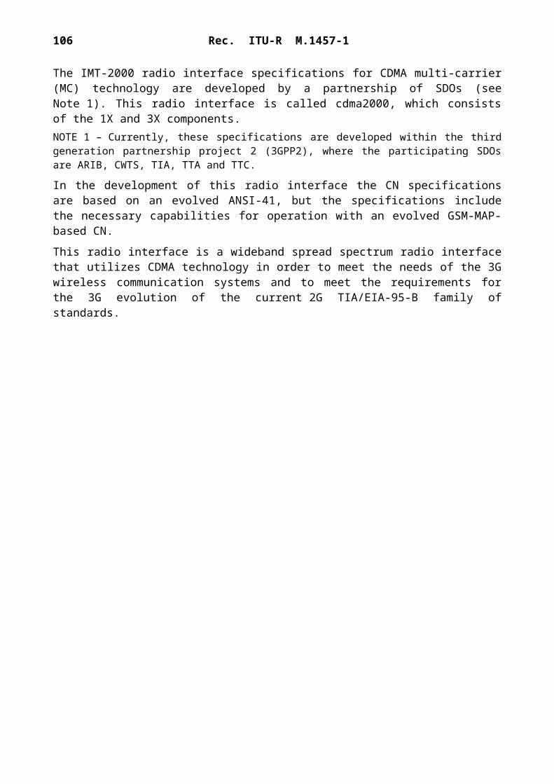
106 Rec. ITU-R M.1457-1
5.3.2.3.9 25.421 UTRAN Iur interface: Layer 1
This specification describes the standards allowed to implement Layer 1 on the Iur interface.The specification of transmission delay requirements and O&M requirements are not in the scope of this document.
5.3.2.3.10 25.422 UTRAN Iur interface: Signalling transport
This specification describes the standards for user data transport protocols and related signalling protocols to establish user plane transport bearers.
5.3.2.3.11 25.423 UTRAN Iur interface: RNSAP signalling
This specification describes the radio network layer signalling procedures between RNCs in UTRAN.
Document No. Version Status Issued date Location(1)
(2) CWTS CWTS STD-DS-25.421 2000 Approved 2000-03 http://www.cwts.org/imt2000/DS
ETSI ETSI TS 125 421 3.0.0 ETSI published 2000-01 http://webapp.etsi.org/pda/home.asp?wki_id=7758
T1 T1TR3GPP 25.421 300 Approved 1999-10 https://www.atis.org/atis/docstore/doc_display.asp?ID=590
TTA TTAE.3G-25.421(T) 1 TA approved 2000-03-28 http://www.tta.or.kr/imt2000/STD-TDD/25421.zip
(1), (2) See Notes (1) and (2), § 5.3.2.1.1.
Document No. Version Status Issued date Location(1)
(2) CWTS CWTS STD-DS-25.422 2000 Approved 2000-03 http://www.cwts.org/imt2000/DS
ETSI ETSI TS 125 422 3.2.0 ETSI published 2000-01 http://webapp.etsi.org/pda/home.asp?wki_id=7759
T1 T1TR3GPP 25.422 340 Approved 2000-06 https://www.atis.org/atis/docstore/doc_display.asp?ID=811
TTA TTAE.3G-25.422(T) 1 TA approved 2000-03-28 http://www.tta.or.kr/imt2000/STD-TDD/25422.zip
(1), (2) See Notes (1) and (2), § 5.3.2.1.1.
Document No. Version Status Issued date Location(1)
(2) CWTS CWTS STD-DS-25.423 2000 Approved 2000-03 http://www.cwts.org/imt2000/DS
ETSI ETSI TS 125 423 3.0.0 ETSI published 2000-01 http://webapp.etsi.org/pda/home.asp?wki_id=7760
T1 T1TR3GPP 25.423 320 Approved 2000-06 https://www.atis.org/atis/docstore/doc_display.asp?ID=812
TTA TTAE.3G-25.423(T) 1 TA approved 2000-03-28 http://www.tta.or.kr/imt2000/STD-TDD/25423.zip
(1), (2) See Notes (1) and (2), § 5.3.2.1.1.

Rec. ITU-R M.1457-1 107
5.3.2.3.12 25.424 UTRAN Iur interface: Data transport and transport signalling for common transport channel data streams
This specification describes a description of the UTRAN RNS-RNS (Iur) interface data transport and transport signalling for common transport channel data streams.
5.3.2.3.13 25.425 UTRAN Iur interface user plane protocols for common transport channel data streams
This specification describes a description of the UTRAN RNS-RNS (Iur) interface user plane protocols for common transport channel data streams.
5.3.2.3.14 25.426 UTRAN Iur and Iub interface data transport and transport signalling for DCH data streams
This specification describes the transport bearers for the DCH data streams on UTRAN Iur and Iub interfaces. The corresponding transport network control plane is also specified. The physical layer for the transport bearers is outside the scope of this TS.
Document No. Version Status Issued date Location(1)
(2) CWTS CWTS STD-DS-25.424 2000 Approved 2000-03 http://www.cwts.org/imt2000/DS
ETSI ETSI TS 125 424 3.1.0 ETSI published 2000-01 http://webapp.etsi.org/pda/home.asp?wki_id=7761
T1 T1TR3GPP 25.424 310 Approved 1999-10 https://www.atis.org/atis/docstore/doc_display.asp?ID=593
TTA TTAE.3G-25.424(T) 1 TA approved 2000-03-28 http://www.tta.or.kr/imt2000/STD-TDD/25424.zip
(1), (2) See Notes (1) and (2), § 5.3.2.1.1.
Document No. Version Status Issued date Location(1)
(2) CWTS CWTS STD-DS-25.425 2000 Approved 2000-03 http://www.cwts.org/imt2000/DS
ETSI ETSI TS 125 425 3.0.0 ETSI published 2000-01 http://webapp.etsi.org/pda/home.asp?wki_id=7762
T1 T1TR3GPP 25.425 Approved 2000-06 https://www.atis.org/atis/docstore/doc_display.asp?ID=814
TTA TTAE.3G-25.425(T) 1 TA approved 2000-03-28 http://www.tta.or.kr/imt2000/STD-TDD/25425.zip
(1), (2) See Notes (1) and (2), § 5.3.2.1.1.
Document No. Version Status Issued date Location(1)
(2) CWTS CWTS STD-DS-25.426 2000 Approved 2000-03 http://www.cwts.org/imt2000/DS
ETSI ETSI TS 125 426 3.1.0 ETSI published 2000-01 http://webapp.etsi.org/pda/home.asp?wki_id=7763
T1 T1TR3GPP 25.426 310 Approved 1999-10 https://www.atis.org/atis/docstore/doc_display.asp?ID=595
TTA TTAE.3G-25.426(T) 1 TA approved 2000-03-28 http://www.tta.or.kr/imt2000/STD-TDD/25426.zip
(1), (2) See Notes (1) and (2), § 5.3.2.1.1.

108 Rec. ITU-R M.1457-1
5.3.2.3.15 25.427 UTRAN Iur and Iub interface: User plane protocol for DCH data streams
This specification describes the UTRAN Iur and Iub interfaces user plane protocols for dedicated transport channel data streams.
5.3.2.3.16 25.430 UTRAN Iub interface: General aspects and principles
This specification describes an introduction to the TSG RAN TS 25.43x series of UMTS technical specifications that define the Iub interface. The Iub interface is a logical interface for the interconnection of Node B and radio network controller (RNC) components of the UTRAN.
5.3.2.3.17 25.431 UTRAN Iub interface Layer 1This specification describes the standards allowed to implement Layer 1 on the Iub interface.The specification of transmission delay requirements and O&M requirements is not in the scope of this document.
Document No. Version Status Issued date Location(1)
(2) CWTS CWTS STD-DS-25.427 2000 Approved 2000-03 http://www.cwts.org/imt2000/DS
ETSI ETSI TS 125 427 3.1.0 ETSI published 2000-01 http://webapp.etsi.org/pda/home.asp?wki_id=7764
T1 T1TR3GPP 25.427 330 Approved 2000-06 https://www.atis.org/atis/docstore/doc_display.asp?ID=816
TTA TTAE.3G-25.427(T) 1 TA approved 2000-03-28 http://www.tta.or.kr/imt2000/STD-TDD/25427.zip
(1), (2) See Notes (1) and (2), § 5.3.2.1.1.
Document No. Version Status Issued date Location(1)
(2) CWTS CWTS STD-DS-25.430 2000 Approved 2000-03 http://www.cwts.org/imt2000/DS
ETSI ETSI TS 125 430 3.0.0 ETSI published 2000-01 http://webapp.etsi.org/pda/home.asp?wki_id=7765
T1 T1TR3GPP 25.430 320 Approved 2000-06 https://www.atis.org/atis/docstore/doc_display.asp?ID=817
TTA TTAE.3G-25.430(T) 1 TA approved 2000-03-28 http://www.tta.or.kr/imt2000/STD-TDD/25430.zip
(1), (2) See Notes (1) and (2), § 5.3.2.1.1.
Document No. Version Status Issued date Location(1)
(2) CWTS CWTS STD-DS-25.431 2000 Approved 2000-03 http://www.cwts.org/imt2000/DS
ETSI ETSI TS 125 431 3.0.0 ETSI published 2000-01 http://webapp.etsi.org/pda/home.asp?wki_id=7766
T1 T1TR3GPP 25.431 300 Approved 1999-10 https://www.atis.org/atis/docstore/doc_display.asp?ID=598
TTA TTAE.3G-25.431(T) 1 TA approved 2000-03-28 http://www.tta.or.kr/imt2000/STD-TDD/25431.zip
(1), (2) See Notes (1) and (2), § 5.3.2.1.1.

Rec. ITU-R M.1457-1 109
5.3.2.3.18 25.432 UTRAN Iub interface: Signalling transport
This specification describes the signalling transport related to NBAP signalling to be used across the Iub interface. The Iub interface is a logical interface for the interconnection of Node B and radio network controller (RNC) components of the UTRAN. The radio network control signalling between these nodes is based on the Node B application part (NBAP).
5.3.2.3.19 25.433 UTRAN Iub interface: NBAP signalling
This specification describes the standards for NBAP specification to be used over Iub interface.
5.3.2.3.20 25.434 UTRAN Iub interface: Data transport and transport signalling for common transport channel data streams
This specification describes a description of the UTRAN RNC-Node B (Iub) interface data transport and transport signalling for CCH data streams.
Document No. Version Status Issued date Location(1)
(2) CWTS CWTS STD-DS-25.432 2000 Approved 2000-03 http://www.cwts.org/imt2000/DS
ETSI ETSI TS 125 432 3.1.0 ETSI published 2000-01 http://webapp.etsi.org/pda/home.asp?wki_id=7767
T1 T1TR3GPP 25.432 310 Approved 1999-10 https://www.atis.org/atis/docstore/doc_display.asp?ID=599
TTA TTAE.3G-25.432(T) 1 TA approved 2000-03-28 http://www.tta.or.kr/imt2000/STD-TDD/25432.zip
(1), (2) See Notes (1) and (2), § 5.3.2.1.1.
Document No. Version Status Issued date Location(1)
(2) CWTS CWTS STD-DS-25.433 2000 Approved 2000-03 http://www.cwts.org/imt2000/DS
ETSI ETSI TS 125 433 3.0.0 ETSI published 2000-01 http://webapp.etsi.org/pda/home.asp?wki_id=7768
T1 T1TR3GPP 25.433 320 Approved 2000-06 https://www.atis.org/atis/docstore/doc_display.asp?ID=818
TTA TTAE.3G-25.433(T) 1 TA approved 2000-03-28 http://www.tta.or.kr/imt2000/STD-TDD/25433.zip
(1), (2) See Notes (1) and (2), § 5.3.2.1.1.
Document No. Version Status Issued date Location(1)
(2) CWTS CWTS STD-DS-25.434 2000 Approved 2000-03 http://www.cwts.org/imt2000/DS
ETSI ETSI TS 125 434 3.1.0 ETSI published 2000-01 http://webapp.etsi.org/pda/home.asp?wki_id=7769
T1 T1TR3GPP 25.434 310 Approved 1999-10 https://www.atis.org/atis/docstore/doc_display.asp?ID=601
TTA TTAE.3G-25.434(T) 1 TA approved 2000-03-28 http://www.tta.or.kr/imt2000/STD-TDD/25434.zip
(1), (2) See Notes (1) and (2), § 5.3.2.1.1.
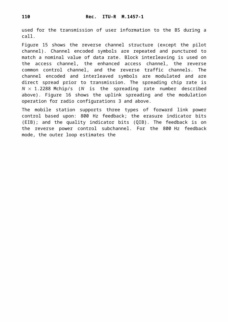
110 Rec. ITU-R M.1457-1
5.3.2.3.21 25.435 UTRAN Iub interface: User plane protocols for common transport channel data streams
This specification describes a description of the UTRAN RNC-Node B (Iub) interface user plane protocols for common transport channel data streams.
5.3.2.3.22 25.442 UTRAN implementation specific O&M transport
This specification describes the transport of implementation specific O&M signalling between Node B and the management platform in case that the transport is routed via the RNC.
5.3.2.4 25.100 series
5.3.2.4.1 25.102 UE radio transmission and reception (TDD)
This specification describes the minimum RF characteristics of the TDD mode of UTRA for the user equipment (UE).
Document No. Version Status Issued date Location(1)
(2) CWTS CWTS STD-DS-25.435 2000 Approved 2000-03 http://www.cwts.org/imt2000/DS
ETSI ETSI TS 125 435 3.1.0 ETSI published 2000-01 http://webapp.etsi.org/pda/home.asp?wki_id=7770
T1 T1TR3GPP 25.435 330 Approved 2000-06 https://www.atis.org/atis/docstore/doc_display.asp?ID=820
TTA TTAE.3G-25.435(T) 1 TA approved 2000-03-28 http://www.tta.or.kr/imt2000/STD-TDD/25435.zip
(1), (2) See Notes (1) and (2), § 5.3.2.1.1.
Document No. Version Status Issued date Location(1)
(2) CWTS CWTS STD-DS-25.442 2000 Approved 2000-03 http://www.cwts.org/imt2000/DS
ETSI ETSI TS 125 442 3.0.0 ETSI published 2000-01 http://webapp.etsi.org/pda/home.asp?wki_id=8666
T1 T1TR3GPP 25.442 300 Approved 1999-10 https://www.atis.org/atis/docstore/doc_display.asp?ID=603
TTA TTAE.3G-25.442(T) 1 TA approved 2000-03-28 http://www.tta.or.kr/imt2000/STD-TDD/25442.zip
(1), (2) See Notes (1) and (2), § 5.3.2.1.1.
Document No. Version Status Issued date Location(1)
(2) CWTS CWTS STD-TDD-401(3) 2000 Approved 2000-03 http://www.cwts.org/tdd
ETSI ETSI TS 125 102 3.1.0 ETSI published 2000-01 http://webapp.etsi.org/pda/home.asp?wki_id=7773
T1 T1TR3GPP 25.102 330 Approved 2000-06 https://www.atis.org/atis/docstore/doc_display.asp?ID=778
TTA TTAE.3G-25.102(T) 1 TA approved 2000-03-28 http://www.tta.or.kr/imt2000/STD-TDD/25102.zip
(1), (2) See Notes (1) and (2), § 5.3.2.1.1.(3) This document establishes the minimum RF characteristics of the TD-SCDMA radio system for the user equipment (UE).

Rec. ITU-R M.1457-1 111
5.3.2.4.2 25.123 Requirements for support of radio resource management (TDD)
This specification describes the requirements for support of radio resource management for TDD including requirements on measurements in UTRAN and the UE as well as on node dynamic behaviour and interaction, in terms of delay and response characteristics.
5.3.2.4.3 25.105 BTS radio transmission and reception (TDD)
This specification describes the minimum RF characteristics of the TDD mode of UTRA.
5.3.2.4.4 25.142 Base station conformance testing (TDD)
This specification describes the radio frequency (RF) test methods and conformance requirements for UTRA base transceiver stations (BTS) operating in the TDD mode. These have been derived from, and are consistent with, the core UTRA specifications specified in the requirements reference sub-clause of each test.
Document No. Version Status Issued date Location(1)
(2) CWTS CWTS STD-TDD-403(3) 2000 Approved 2000-03 http://www.cwts.org/tdd
ETSI ETSI TS 125 123 3.0.0 ETSI published 2000-01 http://webapp.etsi.org/pda/home.asp?wki_id=9753
(1), (2) See Notes (1) and (2), § 5.3.2.1.1.(3) This technical specification shall describe RF parameters and requirements for the radio resource management.
Document No. Version Status Issued date Location(1)
(2) CWTS CWTS STD-TDD-402(3) 2000 Approved 2000-03 http://www.cwts.org/tdd
ETSI ETSI TS 125 105 3.1.0 ETSI published 2000-01 http://webapp.etsi.org/pda/home.asp?wki_id=7774
T1 T1TR3GPP 25.105 330 Approved 2000-06 https://www.atis.org/atis/docstore/doc_display.asp?ID=780
TTA TTAE.3G-25.105(T) 1 TA approved 2000-03-28 http://www.tta.or.kr/imt2000/STD-TDD/25105.zip
(1), (2) See Notes (1) and (2), § 5.3.2.1.1.(3) This document establishes the minimum RF characteristics of TD-SCDMA radio system for the BTS.
Document No. Version Status Issued date Location(1)
(2) CWTS CWTS STD-TDD-301(3) 2000 Approved 2000-03 http://www.cwts.org/tdd
ETSI ETSI TS 125 142 3.0.0 ETSI published 2000-01 http://webapp.etsi.org/pda/home.asp?wki_id=7777
T1 T1TR3GPP 25.142 320 Approved 2000-06 https://www.atis.org/atis/docstore/doc_display.asp?ID=785
TTA TTAE.3G-25.142(T) 1 TA approved 2000-03-28 http://www.tta.or.kr/imt2000/STD-TDD/25142.zip
(1), (2) See Notes (1) and (2), § 5.3.2.1.1.(3) This specification is produced by WG 1, CWTS.

112 Rec. ITU-R M.1457-1
5.3.2.4.5 C302 UE conformance testing
This specification describes the document being produced by the CWTS.
5.3.2.4.6 25.113 Base station EMC (see Note 1)
This specification describes the assessment of base stations and associated ancillary equipment in respect of electromagnetic compatibility (EMC).NOTE 1 – This specification does not include the antenna port immunity and emissions.
5.3.2.4.7 C404 UE and BTS EMC
This specification describes RF EMC parameters and requirements for both UE and BTS in TD-SCDMA radio system.
5.3.2.5 Core network aspects
5.3.2.5.1 23.108 Mobile radio interface Layer 3 specification core network protocols Stage 2
This specification describes the procedures used at the radio interface for call control (CC), mobility management (MM) and session management (SM). It shall hold examples of the structured procedures.
Document No. Version Status Issued date Location(1)
(2) CWTS http://www.cwts.org
CWTS CWTS STD-TDD-302 2000 Approved 2000-03 http://www.cwts.org/tdd
(1), (2) See Notes (1) and (2), § 5.3.2.1.1.
Document No. Version Status Issued date Location(1)
(2) ETSI ETSI TS 125 113 3.0.0 ETSI published 2000-01 http://webapp.etsi.org/pda/home.asp?wki_id=7778
T1 T1TR3GPP 25.113 300 Approved 1999-12 https://www.atis.org/atis/docstore/doc_display.asp?ID=676
TTA TTAE.3G-25.113(T) 1 TA approved 2000-03-28 http://www.tta.or.kr/imt2000/STD-TDD/25113.zip
(1), (2) See Notes (1) and (2), § 5.3.2.1.1.
Document No. Version Status Issued date Location(1)
(2) CWTS http://www.cwts.org
CWTS CWTS STD-TDD-404 2000 Approved 2000-03 http://www.cwts.org/tdd
(1), (2) See Notes (1) and (2), § 5.3.2.1.1.
Document No. Version Status Issued date Location(1)
(2) ETSI ETSI TS 123 108 3.1.0 ETSI published 2000-01 http://webapp.etsi.org/pda/home.asp?wki_id=8661
T1 T1TR3GPP 23.108 320 Approved 2000-03 https://www.atis.org/atis/docstore/doc_display.asp?ID=768
TTA TTAE.3G-23.108(T) 1 TA approved 2000-03-28 http://www.tta.or.kr/imt2000/STD-TDD/23108.zip
(1), (2) See Notes (1) and (2), § 5.3.2.1.1.

Rec. ITU-R M.1457-1 113
5.3.2.5.2 23.110 UMTS access stratum; services and functions
This specification describes the basis of the detailed specifications of the protocols which rule the information flows, both control and user data, between the access stratum and the parts of UMTS outside the access stratum, and of the detailed specifications of the UTRAN. These detailed specifications are to be found in other technical specifications.
5.3.2.5.3 23.022 Functions related to mobile stations (MS) in idle mode and group receive mode
This specification describes an overview of the tasks undertaken by a mobile station (MS) when in idle mode, that is, switched on but not having a dedicated channel allocated, e.g. not making or receiving a call, or when in group receive mode, that is, receiving a group call or broadcast call but not having a dedicated connection. It also describes the corresponding network functions.
5.3.2.5.4 24.007 Mobile radio interface signalling Layer 3: General aspects
This specification describes the principal architecture of Layer 3 and its sublayers on the GSM Um interface, i.e. the interface between mobile station (MS) and network; for the CM sublayer, the description is restricted to paradigmatic examples, call control, supplementary services, and short message services for non-GPRS services. It also defines the basic message format and error handling applied by the Layer 3 protocols.
Document No. Version Status Issued date Location(1)
(2) ETSI ETSI TS 123 110 3.3.0 ETSI published 2000-01 http://webapp.etsi.org/pda/home.asp?wki_id=4358
T1 T1TR3GPP 23.110 340 Approved 2000-03 https://www.atis.org/atis/docstore/doc_display.asp?ID=769
TTA TTAE.3G-23.110(T) 1 TA approved 2000-03-28 http://www.tta.or.kr/imt2000/STD-TDD/23110.zip
(1), (2) See Notes (1) and (2), § 5.3.2.1.1.
Document No. Version Status Issued date Location(1)
(2) T1 T1TR3GPP 23.022 310 Approved 1999-10 https://www.atis.org/atis/docstore/doc_display.asp?ID=537
TTA TTAE.3G-23.022(T) 1 TA approved 2000-03-28 http://www.tta.or.kr/imt2000/STD-TDD/23022.zip
(1), (2) See Notes (1) and (2), § 5.3.2.1.1.
Document No. Version Status Issued date Location(1)
(2) ETSI ETSI TS 124 007 3.2.0 ETSI published 2000-01 http://webapp.etsi.org/pda/home.asp?wki_id=8775
T1 T1TR3GPP 24.007 340 Approved 2000-06 https://www.atis.org/atis/docstore/doc_display.asp?ID=771
TTA TTAE.3G-24.007(T) 1 TA approved 2000-03-28 http://www.tta.or.kr/imt2000/STD-TDD/24007.zip
(1), (2) See Notes (1) and (2), § 5.3.2.1.1.

114 Rec. ITU-R M.1457-1
5.3.2.5.5 24.008 Mobile radio interface Layer 3 specification; core network protocols - Stage 3
This specification describes the procedures used at the radio interface for call control (CC), mobility management (MM) and session management (SM).
The procedures currently described are for the call control of circuit-switched connections, session management for GPRS services, mobility management and radio resource management for circuit-switched and GPRS services.
5.3.2.5.6 24.011 Point-to-point (PP) short message service (SMS); support on mobile radio interface
This specification describes the procedures used across the mobile radio interface by the signalling Layer 3 function short message control (SMC) and short message relay function (SM-RL) for both circuit-switched GSM and GPRS.
5.3.2.5.7 24.012 Short message cell broadcast; support on mobile radio interface
This specification describes how the short message service cell broadcast (SMSCB) is supported over the mobile radio interface.
Document No. Version Status Issued date Location(1)
(2) ETSI ETSI TS 124 008 3.2.1 ETSI published 2000-01 http://webapp.etsi.org/pda/home.asp?wki_id=7893
T1 T1TR3GPP 24.008 341 Approved 2000-07 https://www.atis.org/atis/docstore/doc_display.asp?ID=772
TTA TTAE.3G-24.008(T) 1 TA approved 2000-03-28 http://www.tta.or.kr/imt2000/STD-TDD/24008.zip
(1), (2) See Notes (1) and (2), § 5.3.2.1.1.
Document No. Version Status Issued date Location(1)
(2) ETSI ETSI TS 124 011 3.1.0 ETSI published 2000-01 http://webapp.etsi.org/pda/home.asp?wki_id=8776
T1 T1TR3GPP 24.011 330 Approved 2000-06 https://www.atis.org/atis/docstore/doc_display.asp?ID=774
TTA TTAE.3G-24.011(T) 1 TA approved 2000-03-28 http://www.tta.or.kr/imt2000/STD-TDD/24011.zip
(1), (2) See Notes (1) and (2), § 5.3.2.1.1.
Document No. Version Status Issued date Location (1)
(2) ETSI ETSI TS 124 012 3.0.0 ETSI published 2000-01 http://webapp.etsi.org/pda/home.asp?wki_id=9050
T1 T1TR3GPP 24.012 300 Approved 1999-10 https://www.atis.org/atis/docstore/doc_display.asp?ID=553
TTA TTAE.3G-24.012(T) 1 TA approved 2000-03-28 http://www.tta.or.kr/imt2000/STD-TDD/24012.zip
(1), (2) See Notes (1) and (2), § 5.3.2.1.1.
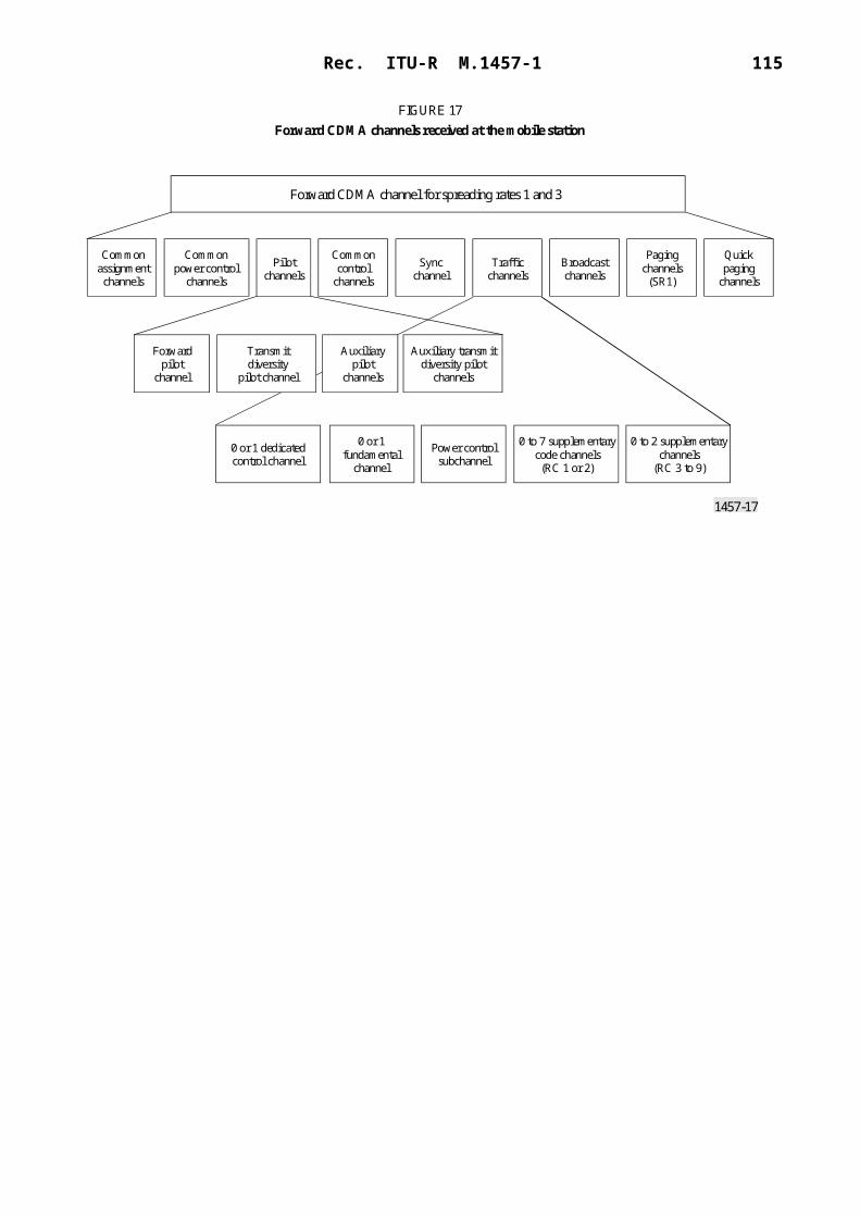
Rec. ITU-R M.1457-1 115
5.3.2.5.8 23.060 General packet radio service (GPRS) service description – Stage 2
This specification describes a general overview over the GPRS architecture as well as a more detailed overview of the MS – core network protocol architecture. Details of the protocols will be specified in companion documents.
5.3.2.5.9 24.022 Radio link protocol (RLP) for circuit-switched bearer and television
This specification describes the radio link protocol (RLP) for data transmission over the UMTS PLMN. RLP covers the Layer 2 functionality of the ISO OSI reference model (IS 7498). It is based on ideas contained in IS 3309, IS 4335 and IS 7809 (HDLC of ISO) as well as ITU-T Recommendations X.25, Q.921 and Q.922 (LAP-B and LAP-D, respectively). RLP has been tailored to the special needs of digital radio transmission. RLP provides to its users the OSI data link service (IS 8886).
5.3.2.5.10 24.010 Mobile radio interface Layer 3 – Supplementary services specification – General aspects
In this specification the general aspects of the specification of supplementary services at the Layer 3 radio interface shall be given. Details will be specified in other documents.
Document No. Version Status Issued date Location(1)
(2) ETSI ETSI TS 123 060 3.2.1 ETSI published 2000-01 http://webapp.etsi.org/pda/home.asp?wki_id=8769
T1 T1TR3GPP 23.060 340 Approved 2000-07 https://www.atis.org/atis/docstore/doc_display.asp?ID=766
TTA TTAE.3G-23.060(T) 1 TA approved 2000-03-28 http://www.tta.or.kr/imt2000/STD-TDD/23060.zip
(1), (2) See Notes (1) and (2), § 5.3.2.1.1.
Document No. Version Status Issued date Location(1)
(2) ETSI ETSI TS 124 022 3.2.0 ETSI published 2000-01 http://webapp.etsi.org/pda/home.asp?wki_id=7896
T1 T1TR3GPP 24.022 330 Approved 2000-06 https://www.atis.org/atis/docstore/doc_display.asp?ID=775
TTA TTAE.3G-24.022(T) 1 TA approved 2000-03-28 http://www.tta.or.kr/imt2000/STD-TDD/24022.zip
(1), (2) See Notes (1) and (2), § 5.3.2.1.1.
Document No. Version Status Issued date Location(1)
(2) ETSI ETSI TS 124 010 3.0.0 ETSI published 2000-01 http://webapp.etsi.org/pda/home.asp?wki_id=8664
T1 T1TR3GPP 24.010 310 Approved 2000-06 https://www.atis.org/atis/docstore/doc_display.asp?ID=773
TTA TTAE.3G-24.010(T) 1 TA approved 2000-03-28 http://www.tta.or.kr/imt2000/STD-TDD/24010.zip
(1), (2) See Notes (1) and (2), § 5.3.2.1.1.

116 Rec. ITU-R M.1457-1
5.3.2.5.11 24.080 Mobile radio interface Layer 3 supplementary service specification – formats and coding
This specification describes the coding of information necessary for support of supplementary service operation on the mobile radio interface Layer 3. Details will be specified in other documents.
5.3.2.6 Terminal aspects
5.3.2.6.1 21.111 USIM and IC card requirements
This specification describes the requirements of the USIM (universal subscriber identity module) and the IC card (UICC). These are derived from the service and security requirements defined in the respective specifications. The document is the basis for the detailed specification of the USIM and the UICC, and the interface to the terminal.
5.3.2.6.2 23.038 Alphabets and language specific information
This specification describes the language specific requirements for the terminals including character coding.
Document No. Version Status Issued date Location(1)
(2) ETSI ETSI TS 124 080 3.1.0 ETSI published 2000-01 http://webapp.etsi.org/pda/home.asp?wki_id=7903
T1 T1TR3GPP 24.080 330 Approved 2000-06 https://www.atis.org/atis/docstore/doc_display.asp?ID=776
TTA TTAE.3G-24.080(T) 1 TA approved 2000-03-28 http://www.tta.or.kr/imt2000/STD-TDD/24080.zip
(1), (2) See Notes (1) and (2), § 5.3.2.1.1.
Document No. Version Status Issued date Location(1)
(2) ETSI ETSI TS 121 111 3.0.1 ETSI published 2000-01 http://webapp.etsi.org/pda/home.asp?wki_id=5817
T1 T1TR3GPP 21.111 320 Approved 2000-07 https://www.atis.org/atis/docstore/doc_display.asp?ID=741
TTA TTAE.3G-21.111(T) 1 TA approved 2000-03-28 http://www.tta.or.kr/imt2000/STD-TDD/21111.zip
(1), (2) See Notes (1) and (2), § 5.3.2.1.1.
Document No. Version Status Issued date Location(1)
(2) ETSI ETSI TS 123 038 3.3.0 ETSI published 2000-01 http://webapp.etsi.org/pda/home.asp?wki_id=8033
T1 T1TR3GPP 23.038 330 Approved 2000-01 https://www.atis.org/atis/docstore/doc_display.asp?ID=658
TTA TTAE.3G-23.038(T) 1 TA approved 2000-03-28 http://www.tta.or.kr/imt2000/STD-TDD/23038.zip
(1), (2) See Notes (1) and (2), § 5.3.2.1.1.

Rec. ITU-R M.1457-1 117
5.3.2.6.3 23.040 Technical realization of the short message service (SMS)
This specification describes the point-to-point short message service (SMS).
5.3.2.6.4 23.041 Technical realization of cell broadcast service (CBS)
This specification describes the point-to-multipoint cell broadcast service (CBS).
5.3.2.6.5 23.042 Compression algorithm for text messaging services
This specification describes the compression algorithm for text messaging services.
Document No. Version Status Issued date Location(1)
(2) ETSI ETSI TS 123 040 3.3.0 ETSI published 2000-01 http://webapp.etsi.org/pda/home.asp?wki_id=8032
T1 T1TR3GPP 23.040 350 Approved 2000-07 https://www.atis.org/atis/docstore/doc_display.asp?ID=764
TTA TTAE.3G-23.040(T) 1 TA approved 2000-03-28 http://www.tta.or.kr/imt2000/STD-TDD/23040.zip
(1), (2) See Notes (1) and (2), § 5.3.2.1.1.
Document No. Version Status Issued date Location(1)
(2) ETSI ETSI TS 123 041 3.1.0 ETSI published 2000-01 http://webapp.etsi.org/pda/home.asp?wki_id=8781
T1 T1TR3GPP 23.041 320 Approved 2000-03 https://www.atis.org/atis/docstore/doc_display.asp?ID=765
TTA TTAE.3G-23.041(T) 1 TA approved 2000-03-28 http://www.tta.or.kr/imt2000/STD-TDD/23041.zip
(1), (2) See Notes (1) and (2), § 5.3.2.1.1.
Document No. Version Status Issued date Location(1)
(2) ETSI ETSI TS 123 042 3.1.0 ETSI published 2000-01 http://webapp.etsi.org/pda/home.asp?wki_id=8031
T1 T1TR3GPP 23.042 310 Approved 2000-01 https://www.atis.org/atis/docstore/doc_display.asp?ID=661
TTA TTAE.3G-23.042(T) 1 TA approved 2000-03-28 http://www.tta.or.kr/imt2000/STD-TDD/23042.zip
(1), (2) See Notes (1) and (2), § 5.3.2.1.1.

118 Rec. ITU-R M.1457-1
5.3.2.6.6 27.005 Use of data terminal equipment – Data circuit terminating; equipment (DTE-DCE) interface for cell broadcast service (CBS)
This specification describes three interface protocols for control of SMS functions within a GSM mobile telephone from a remote terminal via an asynchronous interface.
5.3.2.6.7 27.007 AT command set for the user equipment (UE)
This specification describes a profile of AT commands and recommends that this profile be used for controlling mobile equipment (ME) functions and GSM network services from a terminal equipment (TE) through terminal adaptor (TA).
5.3.2.6.8 27.010 Terminal equipment to mobile station (TE-MS) multiplexer protocol
This specification describes a multiplexing protocol between a mobile station and an external data terminal for the purposes of enabling multiple channels to be established for different purposes (e.g. simultaneous SMS and data call).
Document No. Version Status Issued date Location(1)
(2) ETSI ETSI TS 127 005 3.1.0 ETSI published 2000-01 http://webapp.etsi.org/pda/home.asp?wki_id=8036
T1 T1TR3GPP 27.005 310 Approved 2000-01 https://www.atis.org/atis/docstore/doc_display.asp?ID=716
TTA TTAE.3G-27.005(T) 1 TA approved 2000-03-28 http://www.tta.or.kr/imt2000/STD-TDD/27005.zip
(1), (2) See Notes (1) and (2), § 5.3.2.1.1.
Document No. Version Status Issued date Location(1)
(2) ETSI ETSI TS 127 007 3.3.0 ETSI published 2000-01 http://webapp.etsi.org/pda/home.asp?wki_id=8037
T1 T1TR3GPP 27.007 350 Approved 2000-07 https://www.atis.org/atis/docstore/doc_display.asp?ID=824
TTA TTAE.3G-27.007(T) 1 TA approved 2000-03-28 http://www.tta.or.kr/imt2000/STD-TDD/27007.zip
(1), (2) See Notes (1) and (2), § 5.3.2.1.1.
Document No. Version Status Issued date Location(1)
(2) ETSI ETSI TS 127 010 3.2.0 ETSI published 2000-01 http://webapp.etsi.org/pda/home.asp?wki_id=8038
T1 T1TR3GPP 27.010 330 Approved 2000-03 https://www.atis.org/atis/docstore/doc_display.asp?ID=825
TTA TTAE.3G-27.010(T) 1 TA approved 2000-03-28 http://www.tta.or.kr/imt2000/STD-TDD/27010.zip
(1), (2) See Notes (1) and (2), § 5.3.2.1.1.

Rec. ITU-R M.1457-1 119
5.3.2.6.9 27.103 Wide area network synchronization standard
This specification provides a definition of a wide area synchronization protocol. The synchronization protocol is based upon IrMC Level 4.
5.3.2.7 System aspects
IMT-2000 CDMA TDD specification also includes the following documents which are useful and related to this Recommendation.
See § 5.1.2.7.1 to 5.1.2.7.66.
5.3.2.8 Vocabulary
5.3.2.8.1 25.990 Vocabulary
Document 25.990 is a collection of terms and abbreviations related to the baseline documents defining the objectives and systems framework. This document provides a tool for further work on the technical documentation and facilitates their understanding.
5.3.2.9 SDO's complete system standard
Document No. Version Status Issued date Location(1)
(2) ETSI ETSI TS 127 103 3.0.0 ETSI published 2000-01 http://webapp.etsi.org/pda/home.asp?wki_id=8867
T1 T1TR3GPP 27.103 300 Approved 1999-10 https://www.atis.org/atis/docstore/doc_display.asp?ID=617
TTA TTAE.3G-27.103(T) 1 TA approved 2000-03-28 http://www.tta.or.kr/imt2000/STD-TDD/27103.zip
(1), (2) See Notes (1) and (2), § 5.3.2.1.1.
Document No. Version Status Issued date Location(1)
(2) ARIB ARIB TR-T12-25.990 3.0.0 Approved by ARIB Standard Assembly
2000-03-31 http://www.arib.or.jp/IMT-2000/ARIB-STD/STD-T12/25.900.html
ETSI ETSI TS 125 990 3.0.0 ETSI published 2000-01 http://webapp.etsi.org/pda/home.asp?wki_id=8667
T1 T1TR3GPP 25.990 300 Approved 1999-10 https://www.atis.org/atis/docstore/doc_display.asp?ID=604
TTA TTAE.3G-25.990(T) 1 TA approved 2000-03-28 http://www.tta.or.kr/imt2000/STD-TDD/25990.zip
(1), (2) See Notes (1) and (2), § 5.3.2.1.1.
SDO Location
CWTS http://www.cwts.org
ETSI http://webapp.etsi.org/pda/(search string UMTS)
TTA http://www.tta.or.kr

120 Rec. ITU-R M.1457-1
5.4 IMT-2000 TDMA Single-Carrier
5.4.1 Overview of the radio interface
5.4.1.1 Introduction
The IMT-2000 radio interface specifications for TDMA single-carrier technology are developed by TIA TR45.3 with input from the Universal Wireless Communications Consortium. This radio interface is called Universal Wireless Communication-136 (UWC-136), which is specified by American National Standard TIA/EIA-136. It has been developed with the objective of maximum commonality between TIA/EIA-136 and GSM general packet radio service (GPRS).
This radio interface was designed to provide a TIA/EIA-136 (designated as 136)-based radio transmission technology that meets ITU-R's requirements for IMT-2000. It maintains the TDMA community's philosophy of evolution from 1st to 3rd generation systems while addressing the specific desires and goals of the TDMA community for a 3rd generation system.
This radio interface is an attractive and powerful evolutionary step for 136. The technology presented provides for future IMT-2000 services to existing operators, as well as providing new operators competitive features, services and technology. Additionally, the technology provides these same features and services in other bands around the world where regulatory approval has been granted to offer such services.
There is a three component strategy for evolving the 136 technology towards 3rd generation. The strategy consists of enhancing the voice and data capabilities of the 30 kHz channels (designated as 136), adding a 200 kHz carrier component for high-speed data (384 kbit/s) accommodating high mobility (designated as 136HS Outdoor), and adding a 1.6 MHz carrier component for very high-speed data (2 Mbit/s) in low mobility applications (designated as 136HS Indoor). The combined result constitutes this radio interface specification.
The 136HS Outdoor and Indoor components were developed to satisfy the requirements for an IMT-2000 radio transmission technology, with the additional requirement for the consideration of commercially effective evolution and deployment in current 136 networks. Such considerations include flexible spectrum allocation, spectrum efficiency, compatibility with 136 and 136, and support of macrocellular performance at higher mobile speeds.
5.4.1.2 Services
This technology builds on the mature and powerful TIA/EIA-136 standard, which has evolved over many years. Thus, all TIA/EIA-136 services are included, and the capabilities of 384 kbit/s, and 2 Mbit/s high-speed data are added. Through TIA/EIA-136, signalling for both full-rate (3 users/30 kHz) and half-rate (6 users/30 kHz) services is supported.
5.4.1.2.1 Voice services
Three full-rate voice coders are presently defined: VSELP, ACELP, and US1. Enhancements to voice services entail a more robust full-rate voice service using DQPSK modulation, and a low delay and improved tandeming codec for wireless office applications using 8-PSK modulation. An additional slot format for DQPSK results in a link budget improvement of 4 dB in robustness for ACELP.

Rec. ITU-R M.1457-1 121
For 8-PSK a new slot format was defined not only for US1, but also to prepare for 6 users per RF carrier. RF carriers support both DQPSK and 8-PSK modulation formats so that mobiles supporting either modulation can exist on the same carrier to maximize trunking efficiency.
Voice services are supported with robust error correction coding and link quality improvement techniques such as per slot power control. Enhanced reporting mechanisms for frame error rate, real-time C/I, and BER are also defined to aid in RF system engineering.
5.4.1.2.2 Data services
A scalable packet data service having data rates from 11.2 kbit/s to greater than 2 Mbit/s is supported. This packet data service is referred to as GPRS-136 since it uses the higher layer protocols of GPRS, providing upper layer support across all three bearers: 136, 136HS Outdoor, and 136HS Indoor. Packet-switched services are integrated with existing circuit-switched services while maintaining TIA/EIA-136 capabilities. A mobile station in operation on the packet network may automatically move to the circuit network to place and receive calls, then return to the packet network upon completion of a circuit call. Mobile stations in operation on the packet network are also able to support services such as short message service (SMS) and message waiting indications.
The user can access two forms of data network; X.25 and Internet protocol (IP)-based. For IP-based networks the user may have dynamic or static IP allocation. Differing QoS requirements are supported for any data session and multiple simultaneous data sessions are supported. Only the user's subscription and system engineering limit the number of data sessions that are open for a user. The general approach of this integrated data model is to overlay the circuit-switched network nodes with packet data network nodes for service provisioning, registration, mobility management, and accounting. Interworking is provided between the circuit-switched and packet data networks for mobiles capable of both services. This allows a user engaged in an active data transfer to suspend/ resume operation should they wish to make or receive a circuit call.
5.4.1.2.3 Ancillary services
A host of services are offered, some of which are: short messaging, message waiting indication, calling name indication, extended standby time via sleep mode, wireless office (private systems), circuit-switched data, over-the-air activation, over-the-air programming, encryption, broadcast teleservice transport, general UDP transport, and authentication.
5.4.1.3 Layer 1
The basic premise of operation is spectrum on demand. The amount of spectrum allocated at a given time is a function of the service mix that is required. It allows for incremental channels to be allocated and de-allocated as required. The bandwidth associated with each service is tailored to that service. By aggressively managing the spectrum, high spectral efficiency performance is supported as well as underlay cells which can steal spectrum from the overlay network to provide even more capacity in a given geographical region.

122 Rec. ITU-R M.1457-1
The 136 bearer supports both voice and data service on a 30 kHz RF channel. Two modulation types are specified: mandatory /4-DQPSK and optional 8-PSK at a common channel symbol rate of 24.3 ksymbols/s. Channels are spaced 30 kHz apart, centre to centre. Both the voice and data services can operate on either modulation to allow for service differentiation and channel robustness.
The 136HS Outdoor bearer uses a 200 kHz RF carrier to enable the deployment of the high-speed outdoor data services. Two mandatory modulations are specified: GMSK and 8-PSK at a common channel symbol rate of 270.833 ksymbols/s. The channel coding and modulation can be varied to provide an optimal adaptation of throughput versus channel robustness. Channels are spaced 200 kHz apart, centre to centre.
Finally, the 136HS Indoor bearer uses a 1.6 MHz RF carrier to enable the deployment of high-speed indoor data services at greater than 2 Mbit/s. Two mandatory modulations are specified: B-O-QAM and Q-O-QAM at a common channel symbol rate of 2.6 Msymbols/s. The channel modulation can be varied to provide an optimal adaptation of throughput versus channel robustness. Channels are spaced 1 600 kHz apart, centre to centre. Additionally, 136HS Indoor has an optional TDD mode.
5.4.1.4 Layer 2
Layer 2 provides two different types of functionalities: those to support circuit-based operation and those that support packet-based operation.
5.4.1.4.1 Circuit
The modulated/encoded voice is carried over the digital traffic channel (DTC). The connection of the traffic channel is supervised using the coded digital verification colour code (CDVCC) on Layer 2. The mobile station (MS) decodes the CDVCC (either explicitly or implicitly) received from the base station in every DTC time slot, and compares it with the colour code received from the original connection messages or the hand-off message (DVCCs). The MS transmits the CDVCCs to the base station in each burst. The DTC also contains fast and slow associated control channels (FACCH and SACCH) which carry control and supervising messages.
Layer 2 of the digital control channel (DCCH) services requests from and provides indications to Layer 3. On the MS side, Layer 2 services the Layer 3 reverse DCCH (RDCCH) request primitive to initiate a mobile station access attempt on the random access channel (RACH) which is controlled by Layer 2. Layer 2 then performs random or reserve access procedures, and decoding of the shared channel feedback (SCF) status information. Layer 2 issues a forward DCCH (FDCCH) indication primitive to Layer 3 when the MS receives a complete Layer 3 message broadcast or addressed on various FDCCH channels.
On the base station side, Layer 2 services the Layer 3 F-BCCH, E-BCCH, S-BCCH, and SPACH request primitives containing the Layer 3 messages to be sent to the MS. Layer 2 issues an RDCCH indication primitive to deliver to Layer 3 messages received from the MS.
Various Layer 2 protocols can be used to carry RDCCH and FDCCH information in support of Layer 3 messages such as frame segmentation and re-assembly, and ARQ mode of operation. Other functions of the DCCH Layer 2 are: message concatenation of Layer 3 messages, MSID manage-ment, header formatting, and monitoring radio link quality (MRLQ).

Rec. ITU-R M.1457-1 123
5.4.1.4.2 Packet
The overall function Layer 2 provides is to realize radio bearers for Layer 3, taking into consider-ation the requested QoS objectives. Layer 2 is structured into logical link control (LLC), radio link control (RLC), and medium access control (MAC) (RLC and MAC may be combined into one function referred to as MAC).
The LLC is independent of the radio interface. The LLC provides acknowledged or unacknowl-edged data transfer.
Three separate MAC entities are included in a single Layer 2 MAC, one entity to support each type of bearer: 136 bearer, 136HS Outdoor bearer and 136HS Indoor bearer. The main task of the MAC is to dynamically multiplex the radio resource so that the RF resources can be efficiently utilized among multiple users with minimal packet collisions. The MAC supports both an unacknowledged and an acknowledged mode. In acknowledged mode, the MAC is responsible for sequenced delivery of packets to the higher layers, and an error recovery method using a sliding window automatic repeat request is utilized. The MAC also supports transactions with different priorities, and provides QoS information with four levels of priority. This radio interface also supports several unique design features such as implicit addressing and active mobile identity management which provide link quality robustness, and resource efficiency.
The reason why RLC and MAC are considered as belonging to the same sublayer is that both entities have direct access to the physical layer and the LLC sublayer. Furthermore, the LLC protocol does not depend on the radio interface, whereas the RLC/MAC protocol is radio specific.
5.4.1.5 Layer 3
Layer 3 provides two different types of mobility and resource management functionalities: those to support circuit-based operation (136 mobility and resource management) and those that support packet-based operation (GPRS-136 mobility and resource management).
136 mobility management and radio resource management entities at Layer 3 provide circuit-switched services. Layer 3 procedures (known as intelligent roaming) are defined to provide the user access to the optimum circuit-switched service provider. Once the initial control channel selection has been accomplished, cell re-selection and handoff algorithms provide continuity of service. The cell re-selection algorithms include several trigger conditions and selection criteria to provide versatile management capability.
The GSM-based GPRS mobility management function and the 136 mobility management function, operating in parallel, comprise the GPRS-136 mobility manager. The GPRS mobility management function provides packet data mobility management, while the 136 mobility management function provides circuit-switched service mobility management. Together they ensure that the network knows the current location of MS.
The GPRS-136 radio resource management (RRM) entity is similar to the DCCH procedures that control voice resources. The main task of the RRM is to dynamically allocate the radio resource among the bearers so that the RF resources can be efficiently utilized among multiple users. Procedures are defined which will spread the load across multiple packet channels in a given cell. Techniques are outlined that allow for rapid finding of packet resources. Continuity of service is supported via cell re-selection as a mobile traverses multiple cells. The GPRS-136 RRM supports all three packet data bearers defined in this radio interface.

124 Rec. ITU-R M.1457-1
In addition to the management functions Layer 3 provides other capabilities. Layer 3 message construction rules provides backwards compatibility so that a MS or base station can process a message to the extent it understands it. This capability also allows new functions to be easily added for extensibility.
Layer 3 provides a generic R-DATA transport that can function in point-to-point or broadcast mode. This R-DATA transport can carry various teleservice messages without regard to the exact using entity. This generic capability allows various value-added services such as short message services and over-the-air programming to be defined or added to using the common transport.
5.4.1.6 Network
A system is realized by uniquely combining a TIA/EIA-136 TDMA radio interface with a combined TIA/EIA-41 circuit-switched and GPRS packet-switched network. Figure 39 presents the network elements and the associated reference points that comprise this system. The primary TIA/EIA-41 network node visible to the serving GPRS support node (SGSN) is the gateway mobile switching center (MSC)/visitor location register (VLR). The interface between the TIA/EIA-41 gateway MSC/VLR and the SGSN is the Gs' interface, which allows the tunnelling of TIA/EIA-136 signalling messages between the MS and the gateway MSC/VLR. The tunnelling of these signalling messages is performed transparently through the SGSN. Between the MS and the SGSN, the signalling messages are transported using the tunnelling of messages (TOM) protocol layer. TOM uses the LLC unacknowledged mode procedures to transport the signalling messages. Between the SGSN and the gateway MSC/VLR the messages are transported using the BSSAP protocol.
Upon receiving a TIA/EIA-136 signalling message from a MS via the TOM protocol, the SGSN forwards the message to the appropriate gateway MSC/VLR using the BSSAP protocol. Upon receiving a TIA/EIA-136 signalling message from a gateway MSC/VLR via the BSSAP protocol, the SGSN forwards the message to the indicated MS using the TOM protocol.
MS supporting both circuit and packet services (Class B136 MS) perform location updates with the circuit system by tunnelling the registration message to the gateway MSC/VLR. When an incoming call arrives for a given MS, the gateway MSC/VLR associated with the latest registration pages the MS through the SGSN. The page can be a hard page (no Layer 3 information including in the message), in which case, the Gs' interface paging procedures are used by the MSC/VLR and the SGSN. If the circuit page is not for a voice call or, if additional parameters are associated with the page, a Layer 3 page message is tunnelled to the MS by the MSC/VLR. Upon receiving a page, the MS suspends the packet data session and leaves the packet data channel for a suitable DCCH. Broadcast information is provided on the packet control channel to assist the MS with a list of candidate DCCHs. Once on a DCCH, the MS sends a page response. The remaining call setup procedures, such as traffic channel designation, proceed as in a normal page response situation.
A primed interface (e.g. Gs') indicates an ETSI GPRS interface that has been modified specifically for GPRS-136.
The signalling plane between a MS and the gateway MSC/VLR is shown in Fig. 40.

Rec. ITU-R M.1457-1 125
1457-39
FIGURE 39
Signalling interfaceSignalling and data transfer interface
OtherPLMN
TIA/EIA-41MSC/VLR
gateway
TIA/EIA-41MSC/VLR
serving
Note 1 – For simplicity, not all network elements of this system are shown.
TIA/EIA-41HLR
C-D N
GGSN
TS
GPRSHLR
TEPDN
Gc
SGSN
GGSN
SGSNTE MT BSUm'R Gb
GnGp
Gn
QE
GrGs'
C-D
Gi
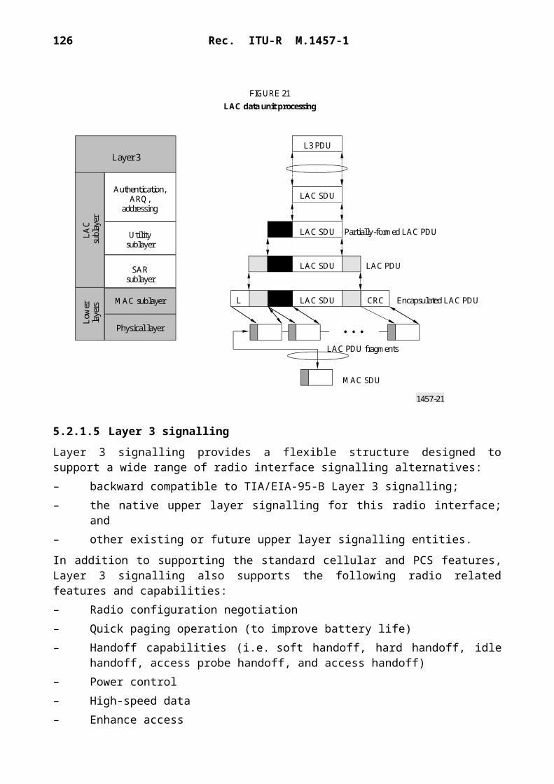
126 Rec. ITU-R M.1457-1
1457-40
FIGURE 40
TIA/EIA-136signalling
Relay
TIA/EIA-136signalling
Relay
Networkservice
Networkservice
TOM
LLC
RLCMAC
RF
MS
RLCMAC
BSSGP
BS
L1bisRF
Um' Gb
L1bis L1
MTP3
MTP2
SCCP
BSSAP+
BSSGP
LLC
TOM
SGSN
BSSAP+
SCCP
L1
MSC/VLR
MTP3
MTP2
Gs'

Rec. ITU-R M.1457-1 127
5.4.1.7 Summary of major technical parameters
Table 6 lists the major technical parameters of this radio interface.
TABLE 6
Parameter Value Reference to § 5.4.2
Multiple access technique TDMA 5.4.2.5.45.4.2.5.125.4.2.5.165.4.2.3.35.4.2.3.6
Carrier spacing:136 bearer136HS Outdoor bearer136HS Indoor bearer
30 kHz200 kHz1.6 MHz
5.4.2.3.2
Carrier symbol rate:136 bearer
136HS Outdoor bearer136HS Indoor bearer
24.3 ksymbols/s
270.833 ksymbols/s2.6 Msymbols/s
5.4.2.5.45.4.2.3.65.4.2.5.125.4.2.5.16
Data modulation: 136 bearer
136HS Outdoor bearer136HS Indoor bearer
/4 DQPSK, 8-PSK
GMSK, 8-PSKBinary offset QAM,Quaternary offset QAM
5.4.2.5.45.4.2.3.65.4.2.5.125.4.2.5.16
Channel coding:136 bearer
136HS Outdoor bearer136HS Indoor bearer
Punctured convolutional codes
Punctured convolutional codesPunctured convolutional codes,Type II hybrid ARQ
5.4.2.5.55.4.2.3.65.4.2.5.15.4.2.5.25.4.2.5.125.4.2.5.16
Frame structure:Frame length136 bearer
136HS Outdoor bearer136HS Indoor bearer
Number of slots per frame136 bearer136HS Outdoor bearer136HS Indoor bearer
40 ms
4.615 (120/26) ms4.615 (120/26) ms
6816-64
5.4.2.5.45.4.2.3.35.4.2.3.65.4.2.5.125.4.2.5.16
5.4.2.5.45.4.2.5.125.4.2.5.16
Minimum operating bandwidth136HS Outdoor bearer136HS Indoor bearer
2 600 kHz2 1.6 MHz FDD 1 1.6 MHz TDD
5.4.2.10.6
Spectrum efficiency136 bearer (voice)136HS Outdoor bearer
136HS Indoor bearer
58.8 E/MHz/cell (3 sectors)0.9495 Mbit/s/MHz/cell (pedestrian A)1.1760 Mbit/s/MHz/cell (vehicule A50)1.0380 Mbit/s/MHz/cell (vehicule A120)0.332 Mbit/s/MHz/cell (indoor A)
5.4.2.10.6
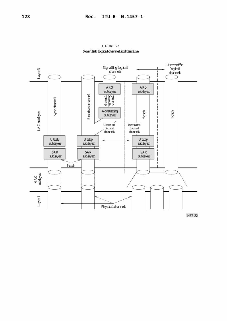
128 Rec. ITU-R M.1457-1
TABLE 6 (end)
5.4.2 Detailed specifications of the radio interface
The standards contained in this section are derived from the global core specifications for IMT-2000 contained at http://ties.itu.int/u/itu-r/ede/rsg8/wp8f/rtech/GCS1457-0/.
American National Standards (ANS) TIA/EIA-136-000 contains a list of all the parts that make up the complete TIA/EIA-136 specification of UWC-136. The parts are organized into subgroups denoted by "nXX". For example, group TIA/EIA-136-4XX contains parts 410, 420 and 430.
Location: http://www.tiaonline.org/standards/sfg/imt2k/uwc136.
5.4.2.1 TIA/EIA-136 UWC-136
5.4.2.1.1 TIA/EIA-136-000 List of parts
Version: Revision B Issued: 2000-03-31 Status: Published ANS
This part outlines the intended scope of the TIA/EIA-136 standard and details the list of parts comprising the current revision.
5.4.2.2 TIA/EIA-136-0XX Miscellaneous information
5.4.2.2.1 TIA/EIA-136-005 Introduction, identification and semi-permanent memory
Version: Revision A Issued: 2000-03-31 Status: Published ANS
This part contains explanations of terms along with identity definition and selection as used in all of the parts.
5.4.2.2.2 TIA/EIA-136-010 Optional mobile station facilities
Version: Revision B Issued: 2000-03-31 Status: Published ANS
This part outlines optional mobile station facilities.
Parameter Value Reference to § 5.4.2
Receiver sensitivity136 bearer
136HS Outdoor bearer
136HS Indoor bearer
– 103 dBm (8 km/h) at 3% BER (DQPSK)– 101 dBm (8 km/h) at 3% BER (8-PSK)– 94 dBm (pedestrian B) at 10% BLER– 100 dBm (vehicule A120) at 10% BLER– 95 dBm (indoor A) at 10% BLER
5.4.2.4.4/55.4.2.4.4/55.4.2.4.65.4.2.4.65.4.2.4.6
Standby RF output power – 117 dBm 5.4.2.4.6
Power control Per slot and per carrier 5.4.2.3.65.4.2.5.4
Variable data rate Supported with slot aggregation and link adaptation 5.4.2.5.45.4.2.5.125.4.2.5.16
Dynamic channel allocation Supported to increase capacity 5.4.2.10.6
Duplexing scheme FDDTDD optional for 136HS indoor
5.4.2.3.25.4.2.5.16
Frequency stability BS: 0.05 ppmMS: 0.1 ppm
5.4.2.4.6

Rec. ITU-R M.1457-1 129
5.4.2.2.3 TIA/EIA-136-020 SOC, BSMC, and other code assignments
Version: Revision B Issued: 2000-03-31 Status: Published ANS
This part provides a list of the system operator codes (SOC), base station manufacturer codes (BSMC), carrier specific higher layer protocol identifiers, and broadcast air-interface transport service category assignments.
5.4.2.3 TIA/EIA-136-1XX Channels
5.4.2.3.1 TIA/EIA-136-100 Introduction to channels
Version: Revision B Issued: 2000-03-31 Status: Published ANS
This part provides the protocol reference model, the logical channel definitions, and the Layer 3 message mapping through Layer 2 to the physical layer.
5.4.2.3.2 TIA/EIA-136-110 RF channel assignments
Version: Revision A Issued: 2000-03-31 Status: Published ANS
This part provides RF channel assignments for MS and BS.
5.4.2.3.3 TIA/EIA-136-121 Digital control channel layer 1
Version: Revision A Issued: 1999-11-29 Status: Published ANS
This part describes the digital control channel (DCCH) Layer 1 including the frame structures and channel/subchannel descriptions.
5.4.2.3.4 TIA/EIA-136-122 Digital control channel layer 2
Version: Revision B Issued: 2000-03-31 Status: Published ANS
This part provides the digital control channel (DCCH) Layer 2 service access points, protocols, and ARQ procedures, as well as requirements on the monitoring of radio link quality.
5.4.2.3.5 TIA/EIA-136-123 Digital control channel layer 3
Version: Revision B Issued: 2000-03-31 Status: Published ANS
This part provides the digital control channel (DCCH) Layer 3 description, including the mobile station state diagram, detailed procedures (e.g. intelligent roaming), the Layer 3 message set, information element descriptions, and timer descriptions.
5.4.2.3.6 TIA/EIA-136-131 Digital traffic channel layer 1
Version: Revision B Issued: 2000-03-31 Status: Published ANS
This part describes the digital traffic channel (DTC) Layer 1 including the channel structure, digital voice and data slot formats, modulation, and channel coding for the MS and BS.
5.4.2.3.7 TIA/EIA-136-132 Digital traffic channel layer 2
Version: Revision 0 Issued: 1999-03-03 Status: Published ANS
This part describes Layer 2 for the digital traffic channel (DTC), which consists primarily of supervision information.

130 Rec. ITU-R M.1457-1
5.4.2.3.8 TIA/EIA-136-133 Digital traffic channel layer 3
Version: Revision B Issued: 2000-03-31 Status: Published ANS
This part describes digital traffic channel (DTC) Layer 3, including discontinuous transmission, mobile assisted handoff, charging rate and total charge indication, MS control signalling and formats, smart antenna support, and per-slot power control.
5.4.2.3.9 TIA/EIA-136-140 Analogue control channel
Version: Revision B Issued: 2000-03-31 Status: Published ANS
This part describes the identification call processing, signalling formats, MS and BS requirements for the analogue control channel.
5.4.2.3.10 TIA/EIA-136-150 Analogue voice channel
Version: Revision B Issued: 2000-03-31 Status: Published ANS
This part includes descriptions of the modulation characteristics, charging indication, MS control, and signalling formats for the analogue voice channel.
5.4.2.4 TIA/EIA-136-2XX Minimum performance
5.4.2.4.1 TIA/EIA-136-210 ACELP minimum performance
Version: Revision 0 Issued: 2000-03-31 Status: Published ANS
This part details the BS minimum performance requirements for the ACELP vocoder.
5.4.2.4.2 TIA/EIA-136-220 VSELP minimum performance
Version: Revision 0 Issued: 2000-03-31 Status: Published ANS
This part details the minimum performance requirements for the VSELP vocoder. This standard includes a software distribution.
5.4.2.4.3 TIA/EIA-136-230 US1 minimum performance
Version: Revision 0 Issued: 2000-03-31 Status: Published ANS
This part details the BS minimum performance requirements for the US1 vocoder. This standard includes a software distribution.
5.4.2.4.4 TIA/EIA-136-270 Mobile stations minimum performance
Version: Revision B Issued: 2000-03-31 Status: Published ANS
This part details definitions, methods of measurement, and MS minimum performance requirements operating 136 bearers.
5.4.2.4.5 TIA/EIA-136-280 Base stations minimum performance
Version: Revision B Issued: 2000-03-31 Status: Published ANS
This part details definitions, methods of measurement, and BS minimum performance requirements operating 136 bearers.

Rec. ITU-R M.1457-1 131
5.4.2.4.6 TIA/EIA-136-290 RF Minimum performance requirements for 136HS Outdoor and 136HS Indoor bearers
Version: Revision 0 Issued: 2000-03-31 Status: Published ANS
This part details the RF minimum performance requirements for BS and MS operating 136HS Outdoor and 136HS Indoor bearers.
5.4.2.5 TIA/EIA-136-3XX Data services
5.4.2.5.1 TIA/EIA-136-310 Radio link Protocol 1
Version: Revision A Issued: 2000-03-31 Status: Published ANS
This part specifies a radio link protocol (RLP1) that provides error recovery functions allowing Layer 3 functions to asynchronously transport data octets across a TDMA radio interface utilizing an underlying half-rate, full-rate, double-rate, or triple-rate digital traffic channel as specified in TIA-136-131, 132, and 133.
5.4.2.5.2 TIA/EIA-136-320 Radio link Protocol 2
Version: Revision 0 Issued: 2000-03-31 Status: Published ANS
This part specifies a radio link protocol (RLP2) that allows Layer 3 functions to isochronously transport data octets across a TDMA radio interface utilizing an underlying half-rate, full-rate, double-rate, or triple-rate digital traffic channel as specified in TIA-136-131, 132, and 133.
5.4.2.5.3 TIA/EIA-136-330 Packet-data service – Overview
Version: Revision 0 Issued: 2000-03-31 Status: Published ANS
This part provides an overview of the GPRS-136 packet data service. An overview of the network reference model, BS and MS protocols, channel types, and options are provided. In addition, an overview of the 30 kHz 136 bearer is provided.
5.4.2.5.4 TIA/EIA-136-331 Packet-data service – 136 physical layer
Version: Revision 0 Issued: 2000-03-31 Status: Published ANS
This part provides the 30 kHz 136 physical layer specification including slot formats, frame structure, modulation, and channel coding.
5.4.2.5.5 TIA/EIA-136-332 Packet-data service – 136 medium access control
Version: Revision 0 Issued: 2000-03-31 Status: Published ANS
This part provides the 30 kHz 136 packet data MAC layer specification including MAC PDUs, transaction management, error recovery, and random access control.
5.4.2.5.6 TIA/EIA-136-333 Packet-data service – Logical-link control
Version: Revision 0 Issued: 2000-03-31 Status: Published ANS
This part defines the logical link control (LLC) layer protocol to be used for packet data transfer between the MS and serving GPRS support node (SGSN).

132 Rec. ITU-R M.1457-1
5.4.2.5.7 TIA/EIA-136-334 Packet-data service – Subnetwork dependent convergence protocol
Version: Revision 0 Issued: 2000-03-31 Status: Published ANS
This part provides the description of the subnetwork dependent convergence protocol (SNDCP). The user of the services provided by SNDCP is a packet data protocol (PDP) at the MS or the relay at the serving GPRS support node (SGSN).
5.4.2.5.8 TIA/EIA-136-335 Packet-data service – Radio resource management
Version: Revision 0 Issued: 2000-03-31 Status: Published ANS
This part specifies the radio resource management in a GPRS-136 packet data system. The entities in a GPRS-136 MS and BS that are used to achieve the goals of radio resource management are the radio resource management entity (RRME) and the broadcast management entity (BME) and are both described in this part.
5.4.2.5.9 TIA/EIA-136-336 Packet-data service – Mobility management
Version: Revision 0 Issued: 2000-03-31 Status: Published ANS
This part describes GPRS-136 mobility management and functions such as location tracking and user-identity confidentiality. The GPRS-136 packet data network combines TIA/EIA-41 circuit switched network elements with GPRS network elements.
5.4.2.5.10 TIA/EIA-136-337 Packet-data service – Tunnelling of signalling messages
Version: Revision 0 Issued: 2000-03-31 Status: Published ANS
This part specifies procedures to provide coordination between the TIA/EIA-136 circuit switched services controlled at the mobile switching centre (MSC)/visitors location register (VLR) and the GPRS-136 packet switched services controlled at the serving GPRS support node (SGSN).
5.4.2.5.11 TIA/EIA-136-340 Packet-data service – 136HS Outdoor overview
Version: Revision 0 Issued: 2000-03-31 Status: Published ANS
This part provides an overview of the 200 kHz 136HS outdoor bearer.
5.4.2.5.12 TIA/EIA-136-341 Packet-data service – 136HS Outdoor physical layer
Version: Revision 0 Issued: 2000-03-31 Status: Published ANS
This part provides the 200 kHz 136HS Outdoor bearer physical layer specification including slot formats, frame structure, modulation, and channel coding.
5.4.2.5.13 TIA/EIA-136-342 Packet-data service – 136HS Outdoor RLC/MAC
Version: Revision 0 Issued: 2000-03-31 Status: Published ANS
This part provides the 200 kHz 136HS Outdoor bearer RLC/MAC layer specification including RLC blocks, MAC protocol data units (PDUs), transaction management, error recovery, and random access control.

Rec. ITU-R M.1457-1 133
5.4.2.5.14 TIA/EIA-136-350 Data-service control
Version: Revision A Issued: 2000-03-31 Status: Published ANS
This part provides a description of the user-network commands and responses used to access async data service, fax data service, and other services running over radio link protocol 1.
5.4.2.5.15 TIA/EIA-136-360 Packet-data service – 136HS Indoor overview
Version: Revision 0 Issued: 2000-03-31 Status: Published ANS
This part provides an overview of the 1.6 MHz 136HS indoor bearer.
5.4.2.5.16 TIA/EIA-136-361 Packet-data service – 136HS Indoor physical layer
Version: Revision 0 Issued: 2000-03-31 Status: Published ANS
This part provides the 1.6 MHz 136HS Indoor bearer physical layer specification including slot formats, frame structure, modulation, and channel coding.
5.4.2.5.17 TIA/EIA-136-362 Packet-data service – 136HS Indoor RLC/MAC
Version: Revision 0 Issued: 2000-03-31 Status: Published ANS
This part provides the 1.6 MHz 136HS indoor bearer RLC/MAC layer specification including RLC blocks, MAC PDUs, transaction management, error recovery, and random access control.
5.4.2.6 TIA/EIA-136-4XX Voice coders
5.4.2.6.1 TIA/EIA-136-410 ACELP
Version: Revision 0 Issued: 1999-11-29 Status: Published ANS
This part gives a bit exact description of the ACELP speech and channel codec for a TIA enhanced full rate codec. The codec consists of a 7.4 kbit/s ACELP speech codec and two channel codecs (forward error correction): channel coding 1 (CC1) a 5.6 kbit/s channel codec and channel coding 2 (CC2), a 6.5 kbit/s channel codec. This standard includes a software distribution.
5.4.2.6.2 TIA/EIA-136-420 VSELP
Version: Revision 0 Issued: 1999-03-03 Status: Published ANS
The speech coding algorithm described in this part is a member of a class of speech codecs known as code excited linear predictive coding (CELP), stochastic coding or vector excited speech coding. These techniques use codebooks to vector quantize the excitation (residual) signal. The speech coding algorithm is a variation on CELP called vector-sum excited linear predictive coding (VSELP).
5.4.2.6.3 TIA/EIA-136-430 US1
Version: Revision 0 Issued: 1999-11-29 Status: Published ANS
This part gives a bit exact description of an enhanced ACELP voice coder which runs over a 136 8-PSK DTC. The codec consists of a 12.2 kbit/s ACELP speech codec and a 7.75 kbit/s channel codec.
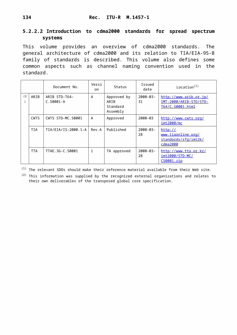
134 Rec. ITU-R M.1457-1
5.4.2.7 TIA/EIA-136-5XX Security
5.4.2.7.1 TIA/EIA-136-510 Authentication, encryption of signalling information/user data, and privacy
Version: Revision B Issued: 2000-03-31 Status: Published ANS
This part provides information on authentication for the digital control channel, analogue voice channel, analogue control channel, and digital traffic channel. It also provides a description of signalling message encryption and voice privacy and data privacy for TIA/EIA-136 systems.
5.4.2.7.2 TIA/EIA-136-511 Messages subject to encryption
Version: Revision A Issued: 2000-03-31 Status: Published ANS
This part describes the messages which are subject to the encryption techniques described in TIA/EIA-136-510.
5.4.2.8 TIA/EIA-136-6XX Teleservice transport
5.4.2.8.1 TIA/EIA-136-610 R-DATA/SMDPP transport
Version: Revision 0 Issued: 2000-03-31 Status: Published ANS
This part describes the transport of TIA/EIA-136 teleservice messages using a combination of the R-DATA message air interface transport and the TIA/EIA-41 SMDPP transport.
5.4.2.8.2 TIA/EIA-136-620 Teleservice segmentation and reassembly (TSAR)
Version: Revision 0 Issued: 1999-11-29 Status: Published ANS
This part describes teleservice segmentation and reassembly (TSAR). TSAR provides a mechanism to deliver TIA/EIA-136 teleservice messages that are not constrained by any message length limitations imposed by the air interface, or network layers supporting the teleservice. The service consists of the application of segmentation and reassembly, and retransmission of errored segments.
5.4.2.8.3 TIA/EIA-136-630 Broadcast teleservice transport – Broadcast air-interface transport service (BATS)
Version: Revision 0 Issued: 1999-11-29 Status: Published ANS
This part describes a broadcast teleservice transport. The BATS teleservice transport operates between a teleservice server and MS using both TIA/EIA-136 and TIA/EIA-41 based protocol stacks along with relay functions in the BS, mobile switching centre and interworking function. BATS is a general-purpose broadcast transport mechanism that can be used by existing teleservices as well as other future teleservices/applications requiring broadcast transport support.
5.4.2.9 TIA/EIA-136-7XX Teleservices
5.4.2.9.1 TIA/EIA-136-700 Introduction to teleservices
Version: Revision B Issued: 2000-03-31 Status: Published ANS
This part provides an introduction to TIA/EIA-136 based teleservices including the teleservice protocol stack, transport, and higher layer protocol identifiers.
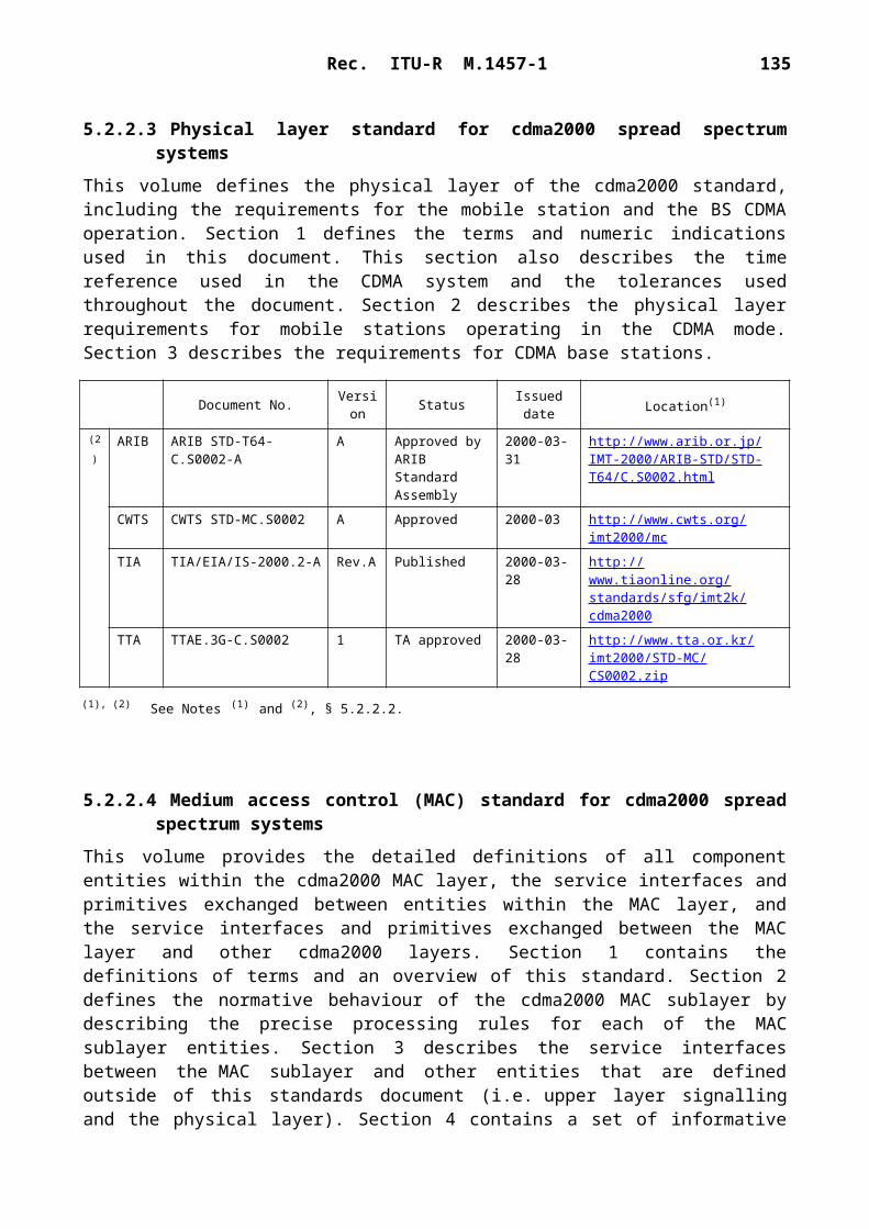
Rec. ITU-R M.1457-1 135
5.4.2.9.2 TIA/EIA-136-710 Short message service – Cellular messaging teleservice
Version: Revision B Issued: 2000-03-31 Status: Published ANS
This part describes the procedures, message set, and information elements necessary to provide short message service in TIA/EIA-136 based systems.
5.4.2.9.3 TIA/EIA-136-720 Over-the-air activation teleservice (OATS)
Version: Revision B Issued: 2000-03-31 Status: Published ANS
This part describes a teleservice that is designed to support over-the-air activation (OTA). The over-the-air activation teleservice (OATS) supports data exchange between a MS and a customer service centre (CSC)/over-the-air activation function (OTAF) which enables downloading information to the MS number assignment module.
5.4.2.9.4 TIA/EIA-136-730 Over-the-air programming teleservice (OPTS)
Version: Revision 0 Issued: 1999-11-29 Status: Published ANS
This part describes a teleservice that is designed to support downloading of non-NAM program-ming information (e.g. intelligent roaming database or IRDB) to an MS. The over-the-air programming teleservice (OPTS) provides a sequence of messages exchanged between the over-the-air service provisioning function (OTASP) and the MS for the delivery of information.
5.4.2.9.5 TIA/EIA-136-750 General UDP transport service (GUTS)
Version: Revision 0 Issued: 1999-11-29 Status: Published ANS
This part describes the general UDP transport service (GUTS), which is a teleservice to support the transport of user datagram protocol (UDP) PDUs between a teleservice server and an MS.
5.4.2.9.6 TIA/EIA-136-760 Charge indication teleservice (CIT)
Version: Revision 0 Issued: 2000-03-31 Status: Published ANS
This part describes a teleservice that is designed to provide the MS user with charge information for a call.
5.4.2.10 TIA/EIA-136-9XX Annexes/Appendices
5.4.2.10.1 TIA/EIA-136-900 Introduction to Annexes and Appendices
Version: Revision 0 Issued: 2000-03-31 Status: Published ANS
This part contains information concerning the 900 series of parts which contain additional normative and informative information related to the TIA/EIA-136 standard.
5.4.2.10.2 TIA/EIA-136-905 Normative information
Version: Revision 0 Issued: 2000-03-31 Status: Published ANS
This part contains additional normative information related to the TIA/EIA-136 standard.

136 Rec. ITU-R M.1457-1
5.4.2.10.3 TIA/EIA-136-910 Informative information
Version: Revision B Issued: 2000-03-31 Status: Published ANS
This part provides additional informative information to aid the user to understand the use or application of the TIA/EIA-136 standard. Information such as frame formats, calculation of R-DATA message lengths and addressing is provided.
5.4.2.10.4 TIA/EIA-136-932 Packet-data service – Stage 2 description
Version: Revision 0 Issued: 2000-03-31 Status: Published ANS
This informative part of TIA/EIA-136 contains stage 2 descriptions for the GPRS-136 packet data service. It describes the main traffic scenarios and the message flows between different network elements.
5.4.2.10.5 TIA/EIA-136-933 Packet-data service – Fixed coding mode MAC
Version: Revision 0 Issued: 2000-03-31 Status: Published ANS
This part describes the fixed-coding mode of the 136 medium access control (MAC) function specified in TIA/EIA-136-332. Higher layers may use the MAC to transport data across a GPRS-136 radio interface using the 136 bearer.
5.4.2.10.6 TIA/EIA-136-940 Capacity and performance characteristics of UWC-136
Version: Revision 0 Issued: 2000-03-31 Status: Published ANS
This informative part contains additional information concerning the voice capacity, spectrum efficiency, and throughput performance for the UWC-136 system.
5.5 IMT-2000 FDMA/TDMA
5.5.1 Overview of the radio interface
5.5.1.1 Introduction
The IMT-2000 radio interface specifications for FDMA/TDMA technology are defined by a set of ETSI standards. This radio interface is called digital enhanced cordless telecommunications (DECT).
Figure 41 shows the layers of this radio interface.
1457-41
FIGURE 41Protocol layered structure
Network (NWK) layer (3)
Data Link Control (DLC) Layer (2b)
Medium Access Control (MAC) Layer (2a)
Physical Layer (PHL) (1)
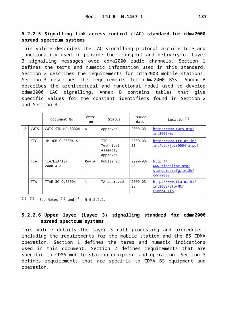
Rec. ITU-R M.1457-1 137
The individual layers are defined in different parts of the common interface (CI) standard. The standard specifies a TDMA radio interface with TDD. The radio frequency bit rates for the specified modulation schemes are 1.152 Mbit/s, 2.304 Mbit/s and 3.456 Mbit/s. The standard supports symmetric and asymmetric connections, connection oriented and connectionless data transport as well as variable bit rates up to 2.88 Mbit/s per carrier. The network layer contains the protocols for call control, supplementary services, connection oriented message service, connection-less message service and mobility management, including the security and confidentiality services.
In addition to the CI standard, access profile standards define minimum requirements for accessing specific networks and the interworking to these networks. For example, the generic access profile (GAP) standard defines the requirements when using the speech service and the DECT packet radio service (DPRS) standard defines the requirements for packet data transport.
A high-level description of features and how the relevant ETSI standards interrelate to the different applications can be found in the ETSI Technical Report TR 101 178: “A high-level guide to the DECT standardization”.
This radio interface is a general radio access technology for wireless telecommunications. It is a high capacity digital technology, for wide cell radii ranging from a few metres to several kilo-metres, depending on application and environment. It provides telephony quality voice services, and a broad range of data services, including ISDN and packet data. It can be effectively implemented in a range from simple residential cordless telephones up to large systems providing a wide range of telecommunications services, including fixed wireless access.
5.5.1.2 General access technology
This technology provides a comprehensive set of protocols which provide the flexibility to inter-work between numerous different applications and networks. Thus a local and/or public network is not part of this specification. Figure 42 illustrates this.
The radio interface covers, in principle, only the air interface between the fixed part (FP) and portable part (PP). The interworking unit (IWU) between a network and the fixed radio termination (FT) is network specific and is not part of the CI specification, but the profile specifications define IWUs for various networks. Similarly, the end system (ES), the application(s) in a PP is also excluded. The CI specification contains general end-to-end compatibility requirements e.g. on speech transmission. The IWU and ES are also subject to general attachment requirements for the relevant public network, e.g. the PSTN/ISDN.NOTE 1 – An ES depends on the application supported in a PP. For a speech telephony application the ES may be a microphone, speaker, keyboard and display. The ES could equally well be a serial computer port, a fax machine or whatever the application requires.
For each specific network, local or global, the specific services and features of that network are made available via the air interface to the users of PPs/handsets. Except for cordless capability and mobility, this standard does not offer a specific service; it is transparent to the services provided by the connected network. Thus the CI standard is, and has to be, a tool box with protocols and messages from which a selection is made to access any specific network, and to provide means for market success for simple residential systems as well as for much more complex systems e.g. office ISDN services.

138 Rec. ITU-R M.1457-1
1457-42
IWU CIPT ES
PP
FP
FT
FIGURE 42The CI structure
Local and/orpublic network
The detailed requirements that have governed the standardization efforts of this interface are provided by the ETR 043 – DECT Common Interface Services and Facilities Requirements Specification – where one requirement is flexibility for additions and evolutionary applications. The CI standard has a layered structure as indicated in § 5.5.2. It contains a complete set of require-ments, procedures and messages. The messages also contain codes that are reserved for evolutionary applications and proprietary extensions. The authentication algorithm and the encryption algorithm are not part of the CI standard, but are obtained from ETSI through a special legal procedure. The administration of global unique identity codes for manufacturing, installation and public operation are also handled by ETSI.
5.5.1.3 Summary of the physical layer
The specification for the physical layer is given in § 5.5.2.1. The tasks of the physical layer can be grouped into five categories:– to modulate and demodulate radio carriers with a bit stream of a defined rate to create a
radio frequency channel;– to acquire and maintain bit and slot synchronization between transmitters and receivers;– to transmit or receive a defined number of bits at a requested time and on a particular
frequency;– to add and remove the synchronization field and the Z-field used for rear end collision
detection;– to observe the radio environment to report signal strengths.
5.5.1.3.1 The physical channels
The radio access frequency channels as well as a time structure are defined. The carrier spacing is 1.728 MHz. To access the medium in time, a regular TDMA structure with a frame length of 10 ms is used. Within this frame 24 full-slots are created, each consisting of two half-slots. A double slot has a length of two full slots, and starts concurrently with an even numbered full slot.

Rec. ITU-R M.1457-1 139
1457-43
FIGURE 43Frame structure using full slot format
Fullslot23
Fullslot0
Fullslot1
Fullslot2
Fullslot11
Fullslot12
Fullslot13
Fullslot23
Fullslot0
Normal RFP transmit Normal PP transmit
Data is transmitted within the frequency, time, and space dimensions using physical packets. Physical packets shall be of one of the following four types:– short physical packet P00 (D-field contains 64 bits):
1457-44
p0 p31 p32 p95
s0 s31 d0 d63
FIGURE 44Packet P00
S field D field
– basic physical packet P32 (the D-field contains 388 bits):
1457-45
p0 p31 p32 p419
s0 s31 d0 d387
p423
z0 z3
Z
FIGURE 45Packet P32
S field D field

140 Rec. ITU-R M.1457-1
– low capacity physical packet P08 (the D-field contains 148 bits):
1457-46
p0 p31 p32 p179
s0 s31 d0 d147 z0 z3
p183
Z
FIGURE 46Packet P08
S field D field
– high capacity physical packet P80 (the D-field contains 868 bits):
1457-47
p0 p31 p32 p899
s0 s31 d0 d867
p903
z0 z3
Z
FIGURE 47Packet P80
S field D field
Each physical packet contains a synchronization field S and a data field D. The packets P80, P32 and P08 may contain an optional collision detection field, Z.
The synchronization field S may be used by the receiver for clock and packet synchronization of the radio link. The first 16 bits are a preamble, and the last 16 bits are the packet synchronization word. A prolonged preamble field which extends the preamble bit pattern by 16 bits is optional. This prolonged preamble field may be used by a receiver for implementation of an antenna selection diversity algorithm.
5.5.1.3.2 The RF carrier modulation
The modulation method is either gaussian frequency shift keying (GFSK), with a bandwidth-bit period product of nominally 0.5 or differential phase shift keying (DPSK). Equipment is allowed to use 4-level and/or 8-level modulation in addition to 2-level modulation. This increases the bit rate of single radio equipment by a factor 2 or 3, which allows for 2 Mbit/s services. For example, the asymmetric double-slot service with modulation configuration 3 provides up to 2.880 Mbit/s B-field data rate per carrier. The 4-level modulation shall be /4-DQPSK and the 8-level modulation /8-D8PSK. It is only allowed to use 4-level and/or 8-level modulation in the B Z or the A B Z fields, whereby the S A or the S field respectively shall use the /2-DBPSK 2-level modulation. The allowed combinations of modulation schemes are defined in Table 7.

Rec. ITU-R M.1457-1 141
TABLE 7
Allowed combinations of modulation schemes
Schemes 2 and 3 ensure that equipment with basic 2-level modulation, and equipment with a higher rate option, can efficiently share a common BS infrastructure. The GFSK modulation can be detected for instance in a non-coherent /2-DPSK receiver, and the /2-DPSK modulation can be detected in a GFSK receiver. Therefore all A-field information including broadcast system information, paging and call control can be received independently of whether configuration 1, 2 or 3 is used.
5.5.1.4 Summary of the MAC layer
The specification for the MAC layer is given in § 5.5.2.2. The MAC layer offers three groups of services to the upper layers and to the management entity:– broadcast message control (BMC);– connectionless message control (CMC);– multi-bearer control (MBC).
The BMC provides a set of continuous point-to-multipoint connectionless services. These are used to carry internal logical channels, and are also offered to the higher layers. These services operate in the direction FT to PT, and are available to all PTs within range.
The CMC provides connectionless point-to-point or point-to-multipoint services to the higher layers. These services may operate in both directions between one specific FT and one or more PTs.
Each instance of MBC provides one of a set of connection oriented point-to-point services to the higher layers. An MBC service may use more than one bearer to provide a single service.
Four types of MAC bearer are defined:– Simplex bearer: a simplex bearer is created by allocating one physical channel for
transmissions in one direction.– Duplex bearer: a duplex bearer is created by a pair of simplex bearers, operating in opposite
directions on two physical channels.– Double simplex: a double simplex bearer is created by a pair of long simplex bearers
operating in the same direction on two physical channels.– Double duplex bearer: a double duplex bearer is composed by a pair of duplex bearers
referring to the same MAC connection.
Configuration S-field A-field B Z-field
1a GFSK GFSK GFSK1b /2-DBPSK /2-DBPSK /2-DBPSK2 /2-DBPSK /2-DBPSK /4-DQPSK3 /2-DBPSK /2-DBPSK /8-D8PSK4a /2-DBPSK /4-DQPSK /4-DQPSK4b /2-DBPSK /8-D8PSK /8-D8PSK

142 Rec. ITU-R M.1457-1
A bearer can exist in one of three operational states:– Dummy bearer: where there are normally continuous transmissions (i.e. one transmission in
every frame).– Traffic bearer: where there are continuous point-to-point transmissions. A traffic bearer is a
duplex bearer or a double simplex bearer or a double duplex bearer.– Connectionless bearer: where there are discontinuous transmissions. A connectionless
bearer is either a simplex or a duplex bearer.
The MAC layer defines a logical structure for the physical channels. The user bit rate depends on the selected slot-type, modulation scheme, level of protection and number of slots. Table 8 gives the user bit rates for unprotected single slot operation.
TABLE 8
Bit rates for single slot operation
5.5.1.5 Summary of the data link control (DLC) layer
The specification for the DLC layer is given in § 5.5.2.3. The DLC layer contains two independent planes of protocol, the C-plane and the U-plane. The C-plane is the control plane of the protocol stacks. The U-plane is the user plane of the protocol stacks.
5.5.1.5.1 C-plane services
The C-plane data link service is provided by two protocol entities called LAPC and Lc. These two protocol entities separate the link access protocol functions from the lower link control functions. The upper LAPC entity uses a protocol derived from the ISDN LAPD protocol. The lower Lc entity buffers and fragments complete LAPC frames (LAPC protocol data units) to/from the MAC layer.
The Lb entity provides a broadcast service in the direction FP to PP. It operates on simple fixed length frames and uses the dedicated MAC layer broadcast service.
5.5.1.5.2 U-plane services
The U-plane services are all optional, in the sense that each service corresponds to a particular requirement, and for any given application only selected services may be implemented. Each U-plane service is divided into two entities, an upper (LUx) entity and a lower (FBx) entity. The upper (LUx) entity contains all of the service dependent functions, and therefore defines the majority of the procedures. The lower (FBx) entity buffers and fragments the complete U-plane frames (LUx protocol data units) to/from the MAC layer. The following family members have been defined:LU1: transparent unprotected service (TRUP) LU2: frame relay service (FREL)
2-level modulation(kbit/s)
4-level modulation(kbit/s)
8-level modulation(kbit/s)
Half slot 8 16 24Full slot 32 64 96Double slot 80 160 240

Rec. ITU-R M.1457-1 143
LU3: frame switching service (FSWI)LU4: FEC serviceLU5: basic rate adaption service (BRAT)LU6: secondary rate adaption service (SRAT)LU7: 64 kbit/s data bearer service with ARQ mechanismLU8: 64 kbit/s data bearer service without ARQ mechanismLU9: unprotected rate adaption for V series equipment (RAVE) serviceLU10: enhanced data serviceLU11: 64 kbit/s data bearer service when A and B fields are both modulated at 4 levelLU12 to LU15: reserved for standard family memberLU16: escape for non-standard family (ESC).
5.5.1.6 Summary of the network (NWK) layer
The specification for the C-plane of the NWK layer is given in § 5.5.2.4. It contains no specification for the U-plane (user plane) because the U-plane is null for all services at the NWK layer.
The NWK layer (Layer 3) protocol contains the following groups of functions:
Link control entity (LCE): The establishment, operation and release of a C-plane link between the fixed termination and every active portable termination.
Call control (CC) entity: The establishment, maintenance and release of circuit-switched calls.
Call independent supplementary services (CISS) entity: The support of call independent supplementary services.
Connection oriented message service (COMS) entity: The support of connection-oriented messages.
Connectionless message service (CLMS) entity: The support of connectionless messages.
Mobility management (MM) entity: The management of identities, authentication, location updating, on-air subscription and key allocation.
In addition all of these C-plane entities interface to the lower layer management entity (LLME). This provides coordination of the operations between different NWK layer entities and also between the NWK layer and the lower layers.
5.5.1.7 Summary of identities and addressing
The specifications for the identities and addressing mechanisms are given in § 5.5.2.5. FP identities are used to inform PPs about the identity of a FP and the access rights to that FP and thereby reduce the number of access attempts from unauthorized portables. A FP broadcasts this information. A PP needs to be able to interpret necessary parts of this broadcast information to detect the access rights to a system or even access rights agreements between system operators, i.e. operators A and B have a bilateral agreement permitting their users to roam between their systems. These agreements can change and cannot therefore be stored in PPs without updating them frequently. Therefore the FP handles access rights information which is embedded in the identity structure. The identity structure provides solutions for residential, public and private environments. This can also be extended to combinations between these environments, e.g. private groups of users within a public network built using this standard, and e.g. public users access to private networks.

144 Rec. ITU-R M.1457-1
1457-48
MNCC SAP MNSS SAP MNCO SAP MNCL SAP MM SAP
CC MMCOMSCLMSCISS
LLME
FIGURE 48Network layer
Protocolcontrol
Interworking unit (IWU)
ProtocolcontrolProtocol
controlProtocolcontrol
Messagesegmenting/reassembly
Data link endpoint and SAP processing
Transactionidentification
Transactionidentification
Transactionidentification
Transactionidentification
Protocol discrimination
Link controlLayer 3link controlentity
Lower layermanagement entity
U-planeconnectionsync
DLC connection orientedSAP (SAPI = 0)
DLC connectionlessSAP (SAPI = 3)
DLC broadcastSAP (SAP B)
PP identities have two main purposes, first to enable a PP to select a valid FP and second to uniquely identify the PP within that FP. For these purposes there are two identities defined. These identities are the portable access rights key (PARK) and the IPUI.
Connection related identities are associated with the peer-to-peer communication. That means that every layer-to-layer connection has an identity. These identities serve the purpose of hand shake, protection against co-channel interference, avoiding loss of a connection during bearer and connection handover, etc.
5.5.1.8 Summary of security features
The specifications for the security architecture, the types of cryptographic algorithms required, the way in which they are to be used, and the requirements for integrating the security features provided by the architecture are given in § 5.5.2.6. It also describes how the features can be managed and how they relate to certain fixed systems and local network configurations. The security architecture is defined in terms of the security services which are to be supported at the CI, the mechanisms which are to be used to provide the services, and the cryptographic parameters, keys and processes which are associated with these mechanisms.

Rec. ITU-R M.1457-1 145
Two basic security services are specified, which are authentication and encryption. The authentication is used to verify the provided identity. There are four forms defined, which are portable authentication, fixed part authentication, mutual authentication and user authentication. Encryption is used to obtain confidentiality of the data which is transmitted over the air.
5.5.1.9 Coexistence of uncoordinated installations on a common frequency band
The mandatory instant dynamic channel selection messages and procedures provide effective coexistence of uncoordinated private and public systems on the common designated frequency band and avoid any need for traditional frequency planning. Each device has access to all channels (time/frequency combinations). When a connection is needed, the channel is selected, that at that instant and at that locality, is least interfered of all the common access channels. This avoids any need for traditional frequency planning, and greatly simplifies the installations. This procedure also provides higher and higher capacity by closer and closer BS installation, while maintaining a high radio link quality. Not needing to split the frequency resource between different services or users gives a very efficient use of the allocated spectrum. There is a large spectrum efficiency gain in sharing spectrum between applications and between operators.
Much unique knowledge and experience is available on the subject of sharing spectrum between uncoordinated installations. Information on this subject has been collected in an ETSI Technical Report, TR 101 310, which describes configurations for typical applications and relevant mixes of these, including residential, office, public and radio local loop (RLL) applications, and the traffic capacity is analysed, mainly by advanced simulations.
5.5.1.10 Access to different systems by the same PP
Each system, FP, has a broadcasted globally unique access rights identity (ARI). To each ARI are linked the available services, the related protocols and when required e.g. a cipher-key and/or authentication-key. For each service suitable protocols have been selected from the CI tool box to efficiently provide these services.
Similarly each PP (handset) has one or more portable access rights keys (PARKs). One PARK relates to one FP or a group of FPs belonging to the same operator. To each PARK are linked the corresponding FP ARIs, related services and protocols, and when required e.g. a ciphering-key and/or authentication-key.
Thus the same PP will have access to several different types of systems, if equipped with the relevant PARKs and associated protocols. Thus, it is basically not a common protocol for all systems that provide intersystem roaming, but it is that the PP is equipped with access rights and related protocols to the wanted systems. A detailed description of the flexible and powerful identity provisions are found in Part 6 of the CI standard.
5.5.1.11 Access to several applications through the same BS
This radio interface also provides the means for sharing BS or systems between different operators or applications, e.g. hosting private user groups in a large public system, providing public access through a privately owned system, or hosting public access to several service providers in one system owned by one of the service providers.

146 Rec. ITU-R M.1457-1
5.5.1.12 Summary of major technical parameters
TABLE 9
Technical parameter Value Reference to § 5.5.2
Multiple access technique TDMA 5.5.2.1
Duplexing scheme TDD 5.5.2.1
Frame length 10 ms 5.5.2.1
Number of time slots in a frame 12 double slots24 full slots48 half slots
5.5.2.1
Modulation GFSK, /2-DBPSK, /4-DQPSK, /8-D8PSK 5.5.2.1
RF bit rate 1 152 kbit/s for 2-level modulation2 304 kbit/s for 4-level modulation3 456 kbit/s for 8-level modulation
5.5.2.1
Channel spacing 1 728 kHz 5.5.2.1
Transmit power Peak powerLevel 1: 2.5 mW (4 dBm)Level 2: 250 mW (24 dBm)
5.5.2.1
Frequency stability For the portable part the centre frequency accuracy shall be within 50 kHz at extreme conditions either relative to an absolute frequency reference or relative to the received carrier, except during the first one second after the transition from the idle-locked state to the active-locked state the centre frequency accuracy shall be within 100 kHz at extreme conditions relative to the received carrier.At an RFP the transmitted RF carrier frequency corresponding to RF channel C shall be in the range FC 50 kHz at extreme conditions. The maximum rate of change of the centre frequency at both the RFP and the PP while transmitting, shall not exceed 15 kHz per slot
5.5.2.1
Adjacent channel leakage power 1 channel: 160 W2 channel: 1 W3 channel: 40 nW>3 channel: 20 nW
5.5.2.1
Transmit linearity requirements The power level of intermodulation products that are on any of this standard's physical channel when any combination of the transmitters at a radio end point are in calls on the same slot on different frequencies shall be less than 1 W. The power level is defined by integration over the 1 MHz centred on the nominal centre frequency of the afflicted channel and averaged over the time period
5.5.2.1
Reference sensitivity – 86 dBm with 1.152 Mbit/s.Sensitivity is measured at 1 103 raw BER
5.5.2.1
Intermodulation sensitivity The level of the interfering signals is – 47 dBm, wanted signal is – 80 dBm and 1 103 raw BER
5.5.2.1

Rec. ITU-R M.1457-1 147
TABLE 9 (end)Technical parameter Value Reference to § 5.5.2
Spurious response and blocking With the desired signal set at – 80 dBm, the BER shall be maintained below 1 103 in the presence of any one of the signals shown in the table belowwhere:FL and FU : lower and the upper edges of the allocated frequency
bandFC : centre frequency of the allocated frequency band
Frequency Interferer level for radiated measure-
ments (dB(V/m))
Interferer level for
conducted measure-
ments(dBm)
25 MHz f FL 100 MHz120 – 23
FL 100 MHz f FL – 5 MHz110 – 33
| f – FC | 6 MHz 100 – 43
FU 5 MHz f FU 100 MHz110 – 33
FU 100 MHz f 12.75 GHz120 – 23
Adjacent channel selectivity With a received signal strength of – 73 dBm (i.e. 70 (dB(V/m)) on RF channel M, the BER in the D-field shall be maintained better than 1 103 when a modulated, reference interferer of the indicated strength is introduced on the RF channels shown below:
5.5.2.1
Interferer on RF channel Y
Interferer signal strength(dB(V/m)) (dBm)
Y M 60 83Y M 1 83 60Y M 2 104 39Y any other channel 110 33
Handover Seamless handover, mobile controlled, triggered when another BS becomes stronger
5.5.2.2, 5.5.2.3, 5.5.2.4
Random access Instant dynamic channel selection for every set-up using the least interfered channel measured at the mobile
5.5.2.2
Pilot structure Broadcast system information available on each active downlink, at least one downlink is active on every BS
5.5.2.2
Dynamic channel allocation Supported 5.5.2.2

148 Rec. ITU-R M.1457-1
5.5.2 Detailed specification of the radio interface
The standards contained in this Section are derived from the global core specifications for IMT-2000 contained at: http://ties.itu.int/u/itu-r/ede/rsg8/wp8f/rtech/GCS1457-0/
The following subsections list the DECT standards, which are relevant for this Recommendation.
5.5.2.1 Physical layer
Title: Digital Enhanced Cordless Telecommunications (DECT);Common Interface (CI);Part 2: Physical Layer (PHL)
Document number: EN 300 175-2Version: V1.4.2Issued date: 1999-06Status: published
Location: http://webapp.etsi.org/pda/home.asp?wki_id=6091
This standard specifies the physical channel arrangements. The tasks of the PHL are to modulate and demodulate radio carriers with a bit stream of a defined rate to create a radio-frequency channel, to acquire and maintain bit and slot synchronization between transmitters and receivers, to transmit or receive a defined number of bits at a requested time and on a particular frequency, to add and remove the synchronization field and the Z-field used for rear end collision detection and to observe the radio environment to report signal strengths.
5.5.2.2 MAC layer
Title: Digital Enhanced Cordless Telecommunications (DECT);Common Interface (CI);Part 3: Medium Access Control (MAC) layer
Document number: EN 300 175-3Version: V1.4.2Issued date: 1999-06Status: published
Location: http://webapp.etsi.org/pda/home.asp?wki_id=6092
This standard specifies the Layer 2a of the DECT protocol stack. It defines three groups of MAC services: the broadcast message control service, the connectionless message control service and the multi-bearer control service. It also specifies the logical channels that are used by the above-mentioned services, and how they are multiplexed and mapped into the Service Data Units that are exchanged with the Physical Layer.
5.5.2.3 Data link control layer
Title: Digital Enhanced Cordless Telecommunications (DECT);Common Interface (CI);Part 4: Data Link Control (DLC) layer
Document number: EN 300 175-4Version: V1.4.2Issued date: 1999-06Status: published
Location: http://webapp.etsi.org/pda/home.asp?wki_id=6093

Rec. ITU-R M.1457-1 149
This standard specifies the Layer 2b of the DECT protocol stack. Two planes of operation are specified for this DLC (sub)layer. These planes are called the Control plane (C-plane) and the User plane (U-plane). The C-plane is mostly concerned with the DECT signalling aspects. It provides a reliable point-to-point service that uses a link access protocol to offer error protected transmission of network layer messages. The C-plane also provides a separate point-to-multipoint (broadcast) service. The U-plane is only concerned with end-to-end user information. This plane contains most of the application dependent procedures of DECT. Several alternative services (both circuit-mode and packet-mode) are defined as a family of independent entities. Each service provides one or more point-to-point U-plane data links, where the detailed characteristics of those links are determined by the particular needs of each service. The defined services cover a wide range of performance, from unprotected with low delay for speech applications to highly protected with variable delay, for local area network applications.
5.5.2.4 Network layer
Title: Digital Enhanced Cordless Telecommunications (DECT);Common Interface (CI);Part 5: Network (NWK) layer
Document number: EN 300 175-5Version: V1.4.2Issued date: 1999-06Status: published
Location: http://webapp.etsi.org/pda/home.asp?wki_id=6094This standard specifies the Layer 3 of the DECT protocol stack. It contains the following groups of functions: Link Control Entity (LCE), Call Control (CC) entity, Call Independent Supplementary Services (CISS) entity, Connection Oriented Message Service (COMS) entity, Connectionless Message Service (CLMS) entity and the Mobility Management (MM) entity.
5.5.2.5 Identities and addressing
Title: Digital Enhanced Cordless Telecommunications (DECT);Common Interface (CI);Part 6: Identities and addressing
Document number: EN 300 175-6Version: V1.4.2Issued date: 1999-06Status: publishedLocation: http://webapp.etsi.org/pda/home.asp?wki_id=6095This standard specifies the identities and addressing structure of the DECT Common Interface. There are four categories of identities defined, which are Fixed Part (FP), Portable Part (PP), connection-related, and equipment-related identities.
5.5.2.6 Security features
Title: Digital Enhanced Cordless Telecommunications (DECT);Common Interface (CI);Part 7: Security features

150 Rec. ITU-R M.1457-1
Document number: EN 300 175-7Version: V1.4.2Issued date: 1999-06Status: publishedLocation: http://webapp.etsi.org/pda/home.asp?wki_id=6096
This part of the DECT CI specifies the security architecture, the types of cryptographic algorithms required, the way in which they are to be used, and the requirements for integrating the security features provided by the architecture into the DECT CI. It also describes how the features can be managed and how they relate to certain DECT fixed systems and local network configurations. The security architecture is defined in terms of the security services which are to be supported at the CI, the mechanisms which are to be used to provide the services, and the cryptographic parameters, keys and processes which are associated with these mechanisms.
5.5.2.7 Radio test specification
Title: Digital Enhanced Cordless Telecommunications (DECT);Approval test specification;Part 1: Radio
Document number: EN 300 176-1Version: V1.3.2Issued date: 1999-06Status: published
Location: http://webapp.etsi.org/pda/home.asp?wki_id=5481
This standard specifies radio tests for DECT equipment. It covers testing of radio-frequency parameters, security elements and those DECT protocols that facilitate the radio-frequency tests and efficient use of frequency spectrum. The aims of this document are to ensure efficient use of frequency spectrum and that no harm is done to other radio networks and services.
6 Recommendations (satellite component)The ITU Radiocommunication Assembly recommends that the principles described in § 6.1 and 6.2 should be applied by satellite systems providing the satellite component of IMT-2000. These sections describe the basic functions and features of the core network interface and the satellite/ terrestrial terminal interface.
The ITU Radiocommunication Assembly recommends that the radio interfaces described in § 6.3 should be those of the satellite component of IMT-2000.
6.1 Core network interface
The satellite component should interface to the core network in a similar manner to the terrestrial component. Key IMT-2000 requirements, such as appropriate call routing, automatic network roaming, common billing, etc. can therefore be supported, subject to technical and market considerations. However some differences may be required to support a specific satellite radio interface.

Rec. ITU-R M.1457-1 151
6.2 Satellite/terrestrial terminal interface
The IMT-2000 satellite user terminals will offer one or more modes of operation: one satellite mode and possibly one or more terrestrial modes. If a terrestrial mode is implemented, terminals should be able to select either satellite or terrestrial modes of operation automatically or under user control.
The satellite/terrestrial terminal interface performs the following functions:– provide the bearer service negotiation capabilities in both terrestrial and satellite networks;– support roaming between terrestrial and satellite networks;– align the service management and provisioning with IMT-2000 Recommendations.
Handover between terrestrial and satellite components is not a requirement of IMT-2000. It is up to the network operator to determine whether to implement handover between the terrestrial and satellite component. If handover is not implemented, roaming between terrestrial and satellite component may be just a switching function i.e. if a user terminal loses its connection to a terrestrial network, it could look for a satellite network.
Terminal locations are registered and updated between the terrestrial and satellite databases by using the standard location updating procedures for updating locations between different public land mobile networks (PLMNs).
For roaming between a terrestrial and a satellite network, standard location update procedures employed by PLMNs can be applied, since both networks can be viewed as separate PLMNs. For example, when a user roams out of the terrestrial network coverage and into satellite coverage, standard procedures for detecting and initiating location updates for roaming among PLMNs is applied. When a user roams into terrestrial network coverage from satellite network coverage and the terminal has the terrestrial network provisioned as the preferred network, the terminal will register into the terrestrial network by initiating procedures for detecting and initiating location updates similar to those used for roaming among PLMNs.
It should be possible to address an IMT-2000 terminal using a single number, regardless of which component (terrestrial or satellite) the terminal is currently using.
6.3 Satellite radio interface specifications
The specification of each satellite radio interface is given in the following subsections. These include only elements related to the service link interface; the feeder link and intersatellite link interfaces are not specified in this Recommendation.
Because of the strong dependency between the radio interface design and overall satellite system optimization, this section includes the architectural and system descriptions as well as the RF and baseband specifications of radio interfaces.
6.3.1 Satellite radio interface A specifications
SW-CDMA is a satellite radio interface designed to meet the requirements of the satellite component of the third generation (3G) wireless communication systems. The SW-CDMA radio interface is currently being examined by the ETSI SES Technical Committee among the family of IMT-2000 satellite radio interfaces as a voluntary standard.

152 Rec. ITU-R M.1457-1
SW-CDMA is based on the adaptation to the satellite environment of the IMT-2000 CDMA Direct Spread terrestrial radio interface (UTRA FDD or WCDMA) (see § 5.1). The intention is to reuse the same core network and reuse the radio interface specifications for the Iu and Cu interface. Only the Uu interface will be adapted to the satellite environment.
SW-CDMA operates in FDD mode with RF channel bandwidth of either 2.350 or 4.700 MHz for each transmission direction. The half rate 2.350 MHz option provides finer spectrum granularity yielding an easier spectrum sharing among different systems.
SW-CDMA provides a wide range of bearer services from 1.2 up to 144 kbit/s. High-quality telecommunication service can be supported including voice quality telephony and data services in a global coverage satellite environment. SW-CDMA deviations from the above-mentioned terrestrial radio interface are summarized hereafter:– Maximum bit rate supported limited to 144 kbit/s– Permanent softer handover forward link operations for constellations providing satellite
diversity– Permanent reverse link satellite diversity combining for constellations providing satellite
diversity– Feeder link (gateway-satellite) and satellite to user link beam centre Doppler pre-
compensation– Two-steps (instead of three-steps as terrestrial) forward link acquisition procedure– Optional half chip-rate mode for improved frequency granularity– Introduction of a high-power paging channel for in-building penetration– Optional (not standard) use of pilot symbols in the communication channels– Reduced power control rate with multi-level predictive power control loop to cope with
longer propagation delay– Shorter scrambling sequence length (2 560 chips) in the forward link– Optional use in the forward link of a short scrambling sequence (256 chips) to allow
CDMA interference mitigation at single user terminal level – Longer random access preamble sequence.
SW-CDMA offers a great degree of commonality with the terrestrial radio interface making the interoperability between the IMT-2000 terrestrial and the satellite components easier.
6.3.1.1 Architectural description
6.3.1.1.1 Channels structure
This radio interface specification is relevant just to the service link, the feeder link not being a part of it.
The service link consists of a forward link, between the satellite station and the MES and a return link in the opposite direction.
At the physical layer, the information flow to and from the MES is conveyed through logical channels as defined in Recommendation ITU-R M.1035. Those logical channels make use of physical channels as bearer medium, as shown in Table 10.

Rec. ITU-R M.1457-1 153
Two broadcast physical channels are foreseen in the forward direction, primary and secondary common control physical channel, CCPCH. The primary CCPCH supports the broadcast control channel (BCCH) used to broadcast system and beam specific information. The secondary CCPCH supports two logical channels namely the forward access channel (FACH), carrying control information to an identified MES when its position is known and a paging channel (PCH), used as high penetration paging channel.
The physical random access channel (PRACH) supports the random access channel (RACH), carrying control information and the random traffic channel (RTCH), carrying short user packets.
The dedicated physical control channel (DPCCH) is used for carrying Layer 1 signalling data.
The dedicated physical data channel (DPDCH) either control information such as higher layers signalling, conveyed through the dedicated control channel (DCCH) and bidirectional user data conveyed through the dedicated traffic channel (DTCH).
TABLE 10
Physical to logical channel mapping
The above bearer services can be utilized to provide circuit-switched and packet data services. On the forward link, packet traffic is supported either on the FACH channel, a downlink shared channel (DSCH) where multiple user services can be supported on the same connection using a time-multiplexed structure or on a dedicated channel for higher throughput requirements. On the reverse link the RACH channel may be utilized for the transmission of occasional short user packets. For a non-occasional, but still moderate throughput and/or low-duty cycle packet traffic, ad hoc codes will be assigned by the LES to the user in order to avoid code collision with other users of the RACH channel. In this case the RTCH is still mapped on a RACH-like physical channel. The data part, however, may be of variable length (in any case a multiple of the physical layer frame length). For higher throughput packet channels on the reverse link, a couple DPCCH/DPDCH can be assigned. The DPDCH is only transmitted when the packet queue is not empty. Also in this case a packet may span multiple physical layer frames. Rate agility is also supported in this case.
Logical channels Physical channels Direction
BCCH Primary CCPCH ForwardFACHPCH
Secondary CCPCH Forward
DSCH PDSCHPDSCCH
ForwardForward
RACHRTCH
PRACH Reverse
DCCH DPDCH BidirectionalDTCH DPDCH Bidirectional
Layer 1 signalling DPCCH Bidirectional
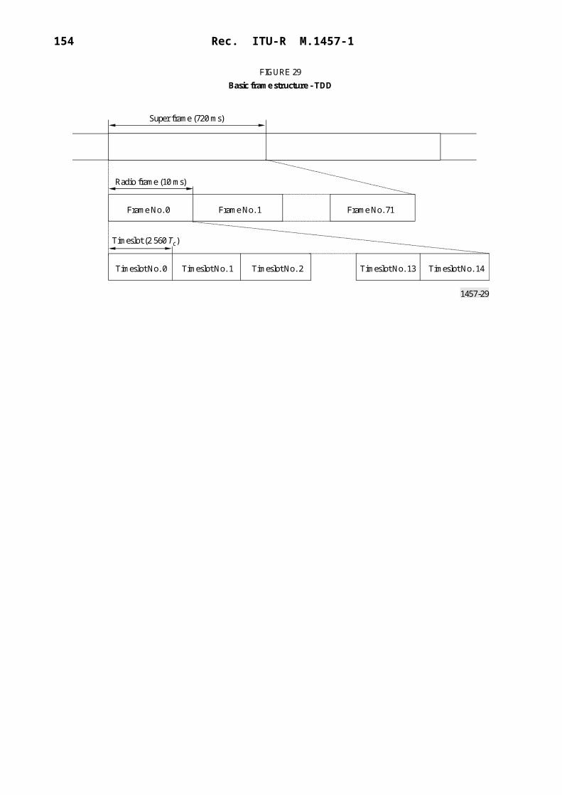
154 Rec. ITU-R M.1457-1
A high penetration messaging service is foreseen as unidirectional service (in the forward direction, i.e. between the satellite station and the MES) supporting low data rates with messages containing some tens of bytes. Its primary scope is a paging service or ring alert for MESs localized inside buildings.
In addition to Recommendation ITU-R M.1035, a dedicated physical channel has been introduced for Layer 1 signalling. This carries reference symbols for channel estimation and synchronization purposes.
6.3.1.1.2 Constellation
SW-CDMA does not compel to any particular constellation. It has been designed to be supported by LEO, MEO, GEO or HEO constellations.
Even though multiple satellite diversity will ensure the best system performances, this shall not be regarded as a mandatory system requirement.
6.3.1.1.3 Satellites
SW-CDMA does not compel to any particular satellite architecture. It can be operated either over a bent-pipe transparent satellite transponder or by regenerative transponder architecture. For the reverse link, satellite path diversity exploitation requires bent-pipe transponder as demodulation takes place on the ground.
6.3.1.2 System description
6.3.1.2.1 Service features
Depending on the MES class, SW-CDMA supports bearer services ranging from 1.2 kbit/s up to 144 kbit/s with associated maximum BER between 1 10–3 to 1 10–6.
The maximum tolerated delay is up to 400 ms, compatible with any of the above-mentioned satellite constellations.
6.3.1.2.2 System features
Both in the forward and in the return link two spreading rates are supported, either 3.840 Mchip/s (full chip rate) and 1.920 Mchip/s (half chip rate).
The transmission is organized in frames. The frame period is 10 ms for the 3.840 Mchip/s option and 20 ms for the 1.920 Mchip/s. Frames are organized in hierarchical structure. A multiframe (MF) consists of 8 frames (full rate option) or 4 frames (half rate option). The MF period is 80 ms. Multiframes are organized in super-frames. One super-frame consists of 9 MFs and has a period equal to 720 ms.
Closed-loop power control is implemented for both the forward and return link. The loop is driven in order to set the measured SNIR value after RAKE fingers combining to a target value. The target value is itself adaptively modified by means of slower outer control loop based on FER measurements. To support FER measurements 8 bit CRC (4 bits for 2 400 bit/s) are appended to data in each frame.
An open loop power control is provided for packet transmission and initial setting of power during the call set-up phase.
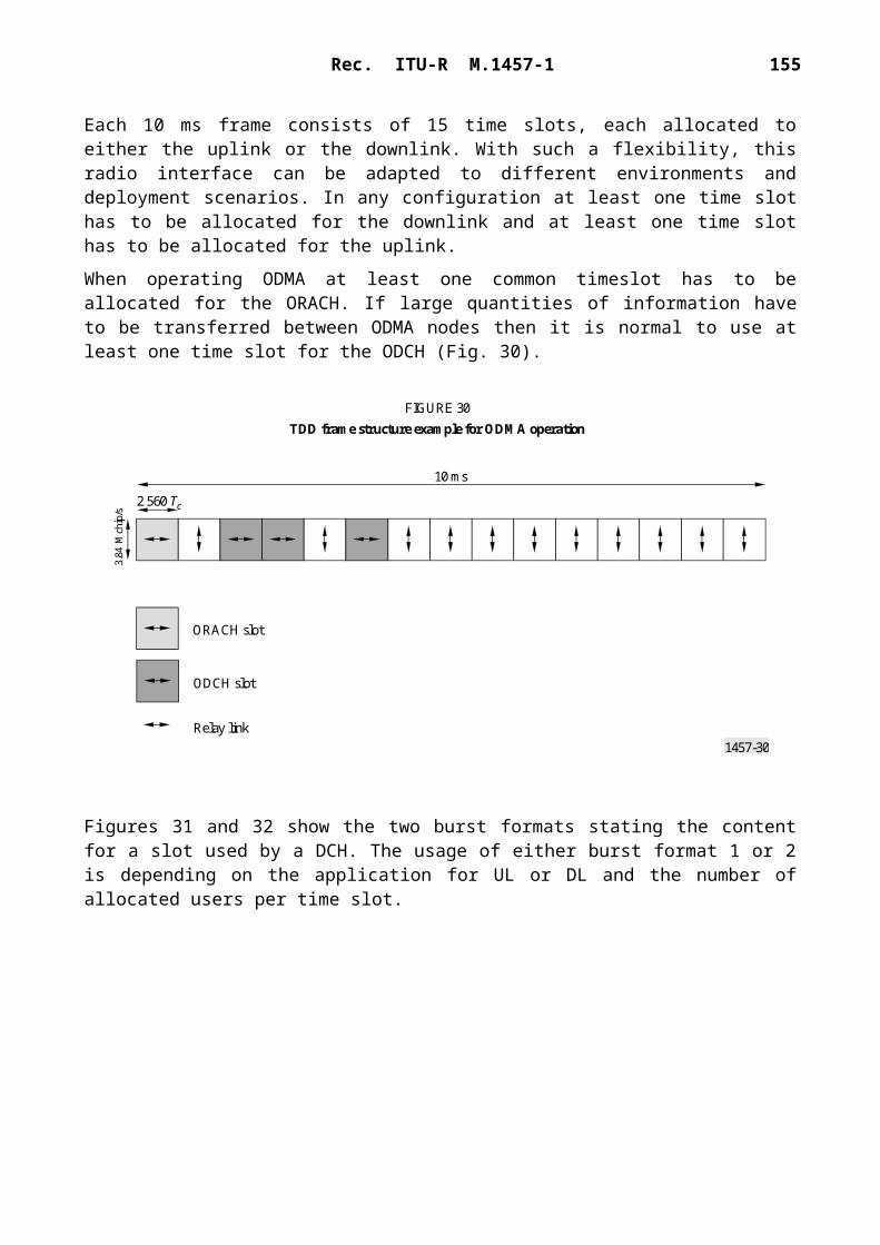
Rec. ITU-R M.1457-1 155
Three basic service classes are supported by a concatenation of coding and interleaving:– standard services with inner coding (rate 1/3 convolutional, polynomials 557, 663, 711) and
interleaving only, with a target BER equal to 1 10–3;– high quality services with inner coding and interleaving plus outer RS coding and
interleaving (or optional Turbo coding). The target BER is 1 10–6;– services with service specific coding. For these services no specific FEC coding technique
is applied by the radio interface. Possible FEC coding is entirely managed at higher layer.
These classes allow to match the various QoS requirements of the selected satellite services and permit QoS enhancements if required through the choice of a service specific coding.
The interleaving scheme is negotiated at call set-up, depending on the actual data rate. The interleaving depth spans over an integer multiple of the frame period. The interleaving block is written per rows over a number of columns which is a power of two, the exponent depending on the actual data rate. In reception, the interleaving block is read per columns in a shuffled sequence, i.e. by reading the binary column index in the reverse order.
Access Description – Forward Link
DPDCH/DPCCH – The DPDCH/DPCCH frame structure is shown in Fig. 49. Each frame is divided in 15 time slots and each time slot carries in time-division multiplexing DPDCH and the corresponding DPCCH.
1457-49
TPC + FCHbits
DPCCH DPDCH
FIGURE 49Frame structure for the forward link dedicated physical channels (DPDCH/DPCCH)
Ts = 0.666 ms or 1.333 ms
Tf = 10 ms or 20 ms
Slot No. iSlot No. 2Slot No. 1 Slot No. 15
Pilotsymbol Data
The DPCCH carries the optional (see Note 1) reference (pilot) symbols, the power control field (TPC) and the frame control header (FCH), which indicates the actual DPDCH format and speed. The reference pilot symbols are optional.
The format and the data rate of the DPDCH may change during the communication session frame by frame: the MES can detect the format and speed of the current frame from the FCH. The DPDCH may even be absent in some frames. As the data rate on the DPDCH changes also the relative power level of DPDCH and DPCCH changes.

156 Rec. ITU-R M.1457-1
The TCP field consists of two bits. For the TPC function only one increase/decrease command per frames is sufficient due to the large loop delay. However, a multi-level loop allows faster reaction to changes into the channel conditions. Hence, an additional bit per frame is allocated for that purpose.
The FCH field consists of three bits. These 3 bits can address eight different DPDCH formats: because the possible DPDCH formats are more than eight, the FCH will actually select a data format in a subset of the available formats which is defined during call set-up negotiation.
The TPC and FCH bits are coded together by mapping the resulting 5-bit word to one 15-bit long sequence (codeword) belonging to a family of 32 sequences. The proposed, length 15 bits, family of sequences is obtained by all the 15 cyclic shift of an ML sequence of length 24 – 1 plus the all zero sequence plus the antipodal of all the previous sequences. The total number of available sequence is thus 32. The cross-correlation between sequences is either 1 or –15. The sequences are either almost orthogonal or antipodal.NOTE 1 – Typically channel estimation is performed by means of the CCPCH thus no pilot symbols are required in the individual DPCCH.
CCPCH – The frame structure of the primary and secondary CCPCH is shown in Fig. 50.
1457-50
FIGURE 50Frame structure for the common control physical channels (CCPCH)
Tf = 10 ms or 20 ms
Slot No. iSlot No. 2Slot No. 1 Slot No. 15
Pilo
tsy
mbo
l
5 data symbols4 FSW symbols
The primary CCPCH is continuously transmitted at a fixed transmission rate (15 kbit/s in the full chip rate option and 7.5 kbit/s in the half chip rate option). It is used to carry the BCH and a frame synchronization word (FSW).
The primary CCPCH channel code for this channel is the same on all beams and satellite and is known to all MES. Two different FSWs are used. One FSW is used on all frames except the first frame of each MF where the other FSW is utilized. It shall be observed that no pilot symbols are used on the CCPCH. The hypothesis is to use the common pilot for such purposes.
The secondary CCPCH carries the paging channel (PCH) and the forward access channel (FACH). This channel is also a constant rate channel and it is transmitted only when user traffic is present. On the secondary CCPCH, the FACH and PCH are time multiplexed on a frame-by-frame basis within the super frame structure. The set of frames allocated to FACH and PCH respectively is broadcast on the BCCH. No power control strategy is implemented in the primary and secondary CCPCH.

Rec. ITU-R M.1457-1 157
PDSCH/PDSCCH – The physical downlink shared channel (PDSCH) carries packet data to MESs without the need to allocate a permanent DCH to each user, which may potentially bring to downlink code shortage. The PDSCH channels use a branch of the OVSF code tree. A single MES per frame is served in case the lowest super frame node of the code branch (i.e. the branch root) is used. Multiple MESs per frame may instead be served via code multiplexing in case a higher super frame factor is used (i.e. lower nodes in the branch tree). All PDSCH channels share a single physical downlink shared control channel (PDSCCH) which is transmitted in code multiplexing and carries code assignment, FCH and TPC information to all users.
Modulation and spreading
The modulation scheme (see Fig. 51) is QPSK where each bit pair is mapped to the I and Q branches. Those are then spread to the chip rate with the same channel code, cch, and subsequently scrambled by the same beam specific complex scrambling code, cscramb.
1457-51
*j
S/P
FIGURE 51QPSK modulation/BPSK spreading for the forward link physical channels
Channelcode
Complexscrambling
code
For the lower user data rates ( 4 800 bit/s), BPSK modulation is used, instead of QPSK modulation, to reduce the sensitivity to phase errors.
The choice of short spreading codes allows the implementation of a linear minimum output energy (MOE) adaptive CDMA demodulator in the MES. The optional use of CDMA MOE detectors is intended to increase system capacity and or/quality of service with no space segment impact.
Codes allocation and synchronization
Scrambling codes – The scrambling code is a complex quaternary sequence of length 2 560 chips. Optionally, in case of MOE-based CDMA interference mitigation at the MES, the use of a shorter (256 chips) real scrambling code is envisaged.
158 Rec. ITU-R M.1457-1
The same scrambling code (staggered by a fixed amount of chips) can be reused in each beam of a given satellite. Different sets of scrambling codes are assigned to each spacecraft. If a given spacecraft is accessed by different LES on the same frequency slot, they must be either mutually synchronized or they shall use different scrambling codes. Depending on orbital parameters, scrambling sequences may be reused among satellites not in simultaneous visibility of the same region. Scrambling code allocation can be done according to several strategies also depending on the constellation and payload (transparent or regenerative) types as well as the degree of synchronization accuracy of LES stations.
The CCPCH common pilot is necessary to support the initial code and frequency acquisition and support satellite diversity operations. The optional use of reference symbols in addition to the common pilot may be required for supporting adaptive antennas.
Channel codes – The channel codes belong to the orthogonal variable spreading factor (OVSF) family. These codes preserve the orthogonality between forward link channels of different rates and spreading factors. Note that as the CCPCH differs from the DPDCH only by the channel code (see Note 2) thus differently from the corresponding terrestrial radio interface the CCPCH is orthogonal to the DPDCH.
The OVSF codes can be defined using the code tree of Fig. 52.
1457-52
C4, 1 = (1, 1, 1, 1)
C4, 2 = (1, 1, –1, –1)C2, 1 = (1, 1)
C1, 1 = (1)
C2, 2 = (1, –1)
C4, 3 = (1, –1, 1, –1)
C4, 4 = (1, –1, –1, 1)
SF1 SF2 SF4
FIGURE 52Code tree generation for OVSF codes
Code tree of OVSF codes
Each level in the code tree defines channel codes of length SFi. All codes within the code tree cannot be used simultaneously within the same beam. A code can be used in a beam if and only if no other code on the path from the specific code to the root or in the underlying sub-tree is in use. This means that the number of available channel codes is not fixed but depends on the rate and spreading factor of each physical channel.NOTE 2 – The CCPCH shares the same DPDCH scrambling sequence.

Rec. ITU-R M.1457-1 159
Acquisition and synchronization
In the MES, the initial acquisition is performed by means of the common pilot. The pilot is modulated with a low rate known pattern and its channelization code is known (typically the all zero sequence code). The known pattern modulating the common pilot has the scope to extend the period of the overall signal in order to support satellite diversity operation. After power on, the MES searches for the scrambling code of the common pilot.
The efficiency of that search and therefore the speed of convergence of the initial acquisition, depends on the number of codes to be searched and possible MES knowledge of candidate satellites. The suggested use of staggered scrambling sequence for the different satellite beams will help in reducing the initial acquisition time. Scrambling sequence reuse among different satellites is also a way to reduce the initial search space dimensions.
Once a pilot has been acquired, the primary CCPCH can be de-spread and the BCCH recovered. This maintains specific information on the list of candidate satellites with the associated scrambling codes in order to accelerate the acquisition of other satellites.
Hand-off
Four possible hand-off situations are envisaged: beam hand-off, satellite hand-off, LES hand-off and frequency hand-off.
Beam hand-off – The MES always measures the de-spread pilot C/(N I) received from adjacent beams and reports measurement results to the LES. When the beam pilot quality is approaching a system threshold level, the LES typically initiates a beam hand-off procedure. According to the MES pilot reports, the LES will decide to transmit the same channel through two different beams (soft beam hand-off) and command the MES to add a finger to demodulate the additional signal. As soon as the LES receives confirmation that the new signal is received, it drops the old beam connection.
Inter-satellite hand-off – The procedure is analogous to that of inter-beam hand-off. The only difference is that the MES has also to search for different pilot scrambling codes. If a new pilot scrambling code is detected, the measure is reported back to the LES, which may decide to exploit satellite diversity by transmitting the same signal through different satellites.
When the satellite constellation provides multiple path diversity, it is useful to operate mobile users in permanent softer hand-off mode. In this case the LES associate the same channel to the strongest satellite diversity paths. The MES exploits path diversity through maximal ratio combining.
Inter-LES hand-off – Inter-LES hand-off may be needed in some cases depending on the constellation characteristics. The inter-LES hand-off shall be negotiated between the LESs. In particular, the new LES starts transmitting its carrier towards the mobile that is simultaneously commanded by the old LES to search for the new LES signal. When the MES confirms to the old LES that it is also receiving from the new one, the old LES stops transmitting towards the MS.
Inter-frequency hand-off – Only hard inter-frequency hand-off is supported. This hand-off can be either intra-gateway or inter-gateway.

160 Rec. ITU-R M.1457-1
Access description – return link
DPDCH/DPCCH frame structure – The DPDCH/DPCCH frame structure in the return link (see Fig. 53) is the same of that in the forward link. However, differently from the forward link, the DPDCH and DPCCH are code and not time-division multiplexed.
1457-53
DPCCH
DPDCH
TCP/FCH1 bit
FIGURE 53Frame structure for the return link dedicated physical channels (DPDCH/DPCCH)
Ts = 0.666 ms or 1.333 ms
Tf = 10 ms or 20 ms
Slot No. iSlot No. 2Slot No. 1 Slot No. 15
Referencesymbols 9 bits
DataN data bits
In the DPCCH, the TCP/FCH field has the same function of that in the forward link. As in the forward link, these bits are mapped to a sequence belonging to a family of 32 sequences. The proposed, length 15 bits, family of sequences is obtained by all the 15 cyclic shift of an ML sequence of length 24–1 plus the all zero sequence plus the antipodal of all the previous sequences. The sequences are either almost orthogonal or antipodal.
The reference bit pattern is described in Table 11. The shadowed part can be used as frame synchronization words. The value of the pilot bit other than the frame synchronization word shall be 1. The frame synchronization word is inverted to mark the beginning of a MF.
The rate at which reference symbols, TPC/FCH bits are transmitted is fixed and equal to 15 kbit/s for the full chip rate option and 7.5 kbit/s for the half chip rate option.
Similarly to the forward link, 2 and 3 bits will be transmitted per frame respectively for the TPC and the FCH functions. – The number of bits per DPDCH slot is related to the spreading factor SF of the physical
channel as SF 256/2k with k 0,….,4. The spreading factor may thus range from 256 down to 16.

Rec. ITU-R M.1457-1 161
TABLE 11
Reference bit pattern for uplink DPCCH
PRACH frame structure – The PRACH frame structure is shown in Fig. 54.
1457-54
FIGURE 54Physical random access channel (PRACH) frame structure
Preamble part Data part
48 symbols 1 frame
The preamble part is formed by modulating a 48 symbols codeword over a spreading code of period 256 chips.
The 48 symbols codeword preamble is randomly selected by the MES in a small set of quaternary codewords. The spreading code is randomly selected between the spreading codes available for random access. Information about the available spreading codes is given on the BCCH channel.
The data part of the RACH burst is actually composed of a data channel on the I transmission arm and an associated control channel on the Q transmission arm carrying the reference symbols for coherent demodulation and a FCH informing about the data rate and format of the I arm. The data
Bit No.Slot No.
0 1 2 3 4 5 6 7 8
123456789
101112131415
111111111111111
110010010100010
111111111111111
000111101001000
111111111111111
011100111000111
111111111111111
100101010000101
111111111111111

162 Rec. ITU-R M.1457-1
rate of the preamble part is instead fixed and equal to 15 ksymbols/s or 7.5 ksymbol/s according to the chip rate option. The length of the data part of the RACH burst is equal to a frame (i.e. 10 or 20 ms, according to the chip rate option).
No diversity combining is supported on the RACH channel.
Modulation and spreading – The modulation/spreading code used in the return link is shown in Fig. 55. Data modulation is BPSK, where the DPDCH and DPCCH are mapped to the carrier I and Q branches respectively. The I and Q branches are then spread to the chip rate with two different channel codes cD/cC and subsequently complex scrambled by a MS specific complex quadri-phase scrambling code.
1457-55
CQ
CI
CQ
CI
b)
a)
I
Q*j
DPDCH
DPCCH
WH
1W
H 2
DPDCH
DPCCH
WHi
WHj
CI+jCQ
I+jQ
FIGURE 55Reverse link spreading modulation scheme for dedicated physical channels a) and its complex representation b)
Spread
Spread
Spread
Spread
Channelizationcodes (OVSF)
I channelSpread
Gain
Gain
Spread

Rec. ITU-R M.1457-1 163
Scrambling code length is one frame (38 400 chips). An option with a short code (256) is being evaluated for use in conjunction with an MMSE-based interference mitigation technique. The scrambling sequences are the same as defined in specification TS25.213 (prepared by 3GPP).
Scrambling codes are assigned to the MES by the LES on a semi-permanent basis.
The channel codes are the same OVSF codes as for the forward link.
6.3.1.2.3 Terminal features
SW-CDMA supports four MES classes: hand-held (H), vehicular (V), transportable (T) and fixed (F). In Table 12 the terminal feature to terminal classes are mapped.
TABLE 12
Bearer services
6.3.1.3 RF specifications
6.3.1.2.4 Satellite station
The satellite station RF specifications depend on the actual space segment architecture.
6.3.1.2.5 MES
In Table 13 the RF specifications for the different MES classes are reported.
Baseband specifications
The baseband specifications are provided in Table 14.
Detailed specifications
The SW-CDMA radio interface detailed specification is based on the following set of documents:– Physical layer: the most recent version of the SW-CDMA documents derived from the
25.200 series (see Note 1).
Bearer data rate (kbit/s) Supported QoS MES class
1.2 10–6 H,V,T,F
2.4 10–3, 10–5, 10–6 H,V,T,F
4.8 10–3, 10–5, 10–6 H,V,T,F
9.6 10–3, 10–5, 10–6 H,V,T,F
16 10–3, 10–5, 10–6 H,V,T,F
32 10–3, 10–5, 10–6 V,T,F
64 10–5, 10–6 V,T,F
144 10–5, 10–6 T,F

164 Rec. ITU-R M.1457-1
– Protocols: most recent versions of the 25.300 draft specifications (see Note 2).NOTE 1 – This set of detailed specifications is presently being elaborated inside the ETSI TC-SES S-UMTS working group among the family of the voluntary standards for IMT-2000 satellite radio interface. This specification will also provide a general description of the physical layer of the SW-CDMA air interface.NOTE 2 – As developed within the 3GPP RAN TSG. These documents can be found on: http://www.3gpp.org/TSG/RAN.html. This specification describes the documents being produced by the 3GPP TSG RAN WG 4.
TABLE 13
MES RF specification
RF parameterMES class
H V T
Channel bandwidth (kHz) 2 350(1),4 700(2)
2 350(1), 4 700(2)
2 350(1), 4 700(2)
Uplink frequency stability (ppm) 3 3 3Downlink frequency stability (ppm) 0.5 0.5 0.5Maximum e.i.r.p. (dBW) 3.0 16.0 16.0Average e.i.r.p. per channel (dBW) (3) (3) (3)
Antenna gain (dBi) – 1.0 2.0(4), 8.0(5) 4.0(4), 25.0(5)
Power control range (dB) 20.0 20.0 20.0Power control step (dB) 0.2-1 0.2-1 0.2-1Power control rate (Hz) 50 100 50 100 50 100Transmit/receive isolation (dB) 169 169 169G/T (dB/K) –23.0(4),
–23.0(5)–23.5(4), –20.0(5)
–23.5(4), –20.0(5)
Doppler shift compensation Yes Yes Not applicableMobility restriction (maximum speed) (km/h)
250(1), 500(2) 250(1), 500(2) Not applicable
(1) Half rate option (1.920 Mchip/s).(2) Full rate option (3.840 Mchip/s).(3) Depending on the satellite station characteristics.(4) Typical value for LEO constellation.(5) Typical value for GEO constellation.

Rec. ITU-R M.1457-1 165
TABLE 14
Baseband characteristics
6.3.2 Satellite radio interface B specifications
W-C/TDMA is a satellite radio interface designed to meet the requirements of the satellite component of the third generation (3G) wireless communication systems (see Note 1).
The W-C/TDMA radio interface is supposed to be compliant with the radio interface CN and related specifications for the Iu and Cu interface.
W-C/TDMA is based on a hybrid code and time-division multiple access (C/TDMA) technique with RF channel bandwidth of either 2.350 or 4.700 MHz for each transmission direction.
W-C/TDMA is characterized by a slotted structure, a quasi-synchronous operation of the uplink resulting in a quasi-orthogonal partitioning of most radio resources of a single, multibeam satellite system.
BB-1 Multiple accessBB-1.1 Technique Direct sequence CDMABB-1.2 Chip rate (where appropriate) 1.920 Mchip/s
or3.840 Mchip/s
BB-1.3 Time slots (where appropriate) 15 time slots per frameBB-2 Modulation type – Dual-code BPSK in the uplink
– QPSK or BPSK in the downlinkBB-3 Dynamic channel allocation (yes/no) NoBB-4 Duplex method (e.g. FDD, TDD) FDDBB-5 FEC – Standard quality: convolutional coding
with code rate 1/3 or 1/2 constraint length k 9. Variable puncturing repetition to match the required info rate.
– High quality concatenated RS code over GF(28), concatenated with inner convolutional code with rate 1/3 or 1/2, constraint length k 9. Turbo coder as option
BB-6 Interleaving – Interleaving on a single frame basis (default).
– Interleaving on a multiple frame basis (optional)
BB-7 Synchronization between satellites required (y/n)
– Synchronization between BSs working on different satellites is not required.
– Synchronization between BSs working on the same satellite is required

166 Rec. ITU-R M.1457-1
According to the relevant IMT-2000 satellite band regulations, the baseline diplexing scheme is FDD: however a TDD/FDD scheme is supported in which the transmission takes place in a different time slot with respect to reception and in different frequency bands. The half rate option provides finer spectrum granularity and robustness with respect to chip synchronization and tracking in channel with high Doppler shift.
W-C/TDMA provides a wide range of bearer services from 1.2 up to 144 kbit/s. High quality telecommunication service can be supported including voice quality telephony and data services in a global coverage satellite environment. W-C/TDMA supports additional features specific of the satellite environment such as the provision of a high penetration paging channel.
The main attractive features of W-C/TDMA are hereafter summarized:– W-C/TDMA provides superior system capacity over a narrow-band TDMA or FDMA
system.– Supports FDD/TDD mode operation requiring terminals with less demanding antenna
diplexers.– Provides more resources allocation flexibility thanks to orthogonal partitioning (TDM/
TDMA) of a high percentage of radio resources on top of CDM/CDMA.– Allows full frequency re-use simplifying frequency planning.– Provision of finer granularity of user data rates compared to narrow-band systems avoiding
high peak-to-mean power. – Provision of accurate user positioning without external means.– Support of high penetration messaging service.NOTE 1 – The W-C/TDMA radio interface is currently being examined by the (ETSI) SES Technical Committee among the family of IMT-2000 satellite radio interfaces as a voluntary standard.
6.3.2.1 Architectural description
6.3.2.1.1 Channels structure
This radio interface specification is relevant just to the service link, the feeder link not being part of it.
The service link consists of a forward link, between the satellite station and the MES and a return link in the opposite direction.
At the physical layer, the information flow to and from the MES is conveyed through logical channels as defined in Recommendation ITU-R M.1035.
Those logical channels make use of physical channels as bearer medium.
W-C/TDMA adopts the same physical channel structure as the terrestrial radio interface. The mapping between physical and logical channels is shown in Table 15.
Two broadcast physical channels are foreseen in the forward direction, primary and secondary common control physical channel, P/S-CCPCH.
The primary CCPCH supports the broadcast control channel (BCCH) used to broadcast system and beam specific information.
The secondary CCPCH supports two logical channels namely the forward access channel (FACH), carrying control information to an identified MES when its position is known.

Rec. ITU-R M.1457-1 167
The physical random access channel (PRACH) supports the random access channel (RACH), carrying control information and the random traffic channel (RTCH), carrying short user packets.
TABLE 15
Physical to logical channel mapping
The dedicated physical control channel (DCPCH) is used for Layer 1 signalling.
The dedicated physical control channel (DDPCH) is used for carrying either control information such as higher layer signalling, conveyed through the dedicated control channel (DCCH) and bidirectional user data conveyed through the dedicated traffic channel (DTCH).
The above bearer services can be utilized to provide circuit-switched and packet data services.
Multiple user services can be supported on the same connection using a time-multiplexed structure.
With respect to that a specific physical control channel has been introduced, HP-CCPCH, supporting, in the forward link the high penetration paging channel, a low data rate service, whose primary scope is as a paging service or ring alert for MESs localized inside buildings.
6.3.2.1.2 Constellation
W-C/TDMA does not compel to any particular constellation. It has been designed to be supported by low, medium, geostationary or high Earth orbit (LEO, MEO, GEO or HEO) constellations.
Even though multiple spot-beam coverage will ensure the best system performances, this shall not be regarded as a mandatory system requirement.
6.3.2.1.3 Satellites
W-C/TDMA does not compel to any particular satellite architecture. It can be operated either over a bent-pipe transparent satellite transponder or by regenerative transponder architecture.
Logical channels Physical channels Direction
BCCH Primary CCPCH ForwardFACH Secondary CCPCH ForwardPilot PI-CCPCH ForwardPCH HP-CCPCH Forward
RACHRTCH
PRACH Reverse
DCCH DDPCH BidirectionalDTCH DDPCH Bidirectional
Layer 1 signalling and pilot symbols
DCPCH Bidirectional

168 Rec. ITU-R M.1457-1
6.3.2.2 System description
6.3.2.2.1 Service features
Depending on the MES class, W-C/TDMA supports bearer services ranging from 1.2 kbit/s up to 144 kbit/s with associated maximum BER between 1 10–3 to 1 10–6.
The maximum tolerated delay is up to 400 ms, compatible with any of the above-mentioned satellite constellations.
6.3.2.2.2 System features
Both in the forward and in the return link two spreading rates are supported, both 3.840 Mchip/s (full chip rate) and 1.920 Mchip/s (half chip rate).
Closed-loop power control is implemented for both the forward and return link. The loop is driven in order to set the measured SNIR value after RAKE combining to a target value. The target value is itself adaptively modified by means of slower outer control loop based on FER measurements. To support FER measurements 8 bit CRC (4 bit for 2 400 bit/s) are appended to data in each frame.
An open loop power control is provided for packet transmission and initial setting of power during the call set-up phase.
Three basic service classes are supported by a concatenation of coding and interleaving:– standard services with inner coding (rate 1/3 convolutional, polynomials 557, 663, 711) and
interleaving only, with a target BER equal to 1 10–3;– high quality services with inner coding and interleaving plus outer RS coding and
interleaving. The target BER after the inner decoding is 1 10–6;– services with service specific coding. For these services no specific FEC coding technique
is applied by the radio interface. Possible FEC coding is entirely managed at higher layer.
These classes allow matching of the various QoS requirements of the selected satellite services and permitting QoS enhancements, if required, through the choice of a service specific coding.
The interleaving scheme is negotiated at call set-up, depending on the actual data rate. The interleaving depth spans over an integer multiple of the frame period. The interleaving block is written per rows over a number of columns, which is a power of two, the exponent depending on the actual data rate. In reception, the interleaving block is read per columns in a shuffled sequence, i.e. by reading the binary column index in the reverse order.
Satellite diversity
In a multiple satellite coverage scenario, the LES may decide to combine return link signals of co-coverage satellites with the return link signal received via the primary satellite to improve the SNIR and to reduce shadowing probability. Since quasi-synchronous operation is restricted to the primary satellite, the resulting SIR at a secondary satellite demodulator where the user is received asynchronously is generally lower. In spite of these SIR inequities, it can be shown that there is a substantial gain from maximal ratio combining techniques which may be used to increase return link power efficiency and capacity.

Rec. ITU-R M.1457-1 169
Access description
In the forward link from the satellite station to the MES an orthogonal CTDM is adopted. In the return link, from the MES to the satellite station quasi-synchronous W-C/TDMA is adopted.
The transmission is organized in frames, as shown in Fig. 56. The frame period is 20 ms and is subdivided in 8 time slots. Frames are organized in multiframes (MF, period 180 ms) consisting of 8 ordinary frames plus one extra frame.
1457-562.5 ms
Slot No. 1Slot No. 0 Slot No. 2 Slot No. 3 Slot No. 4 Slot No. 5 Slot No. 6 Slot No. 7
FIGURE 56Forward and return link frame structure
FrameNo. 1
FrameNo. 0
FrameNo. 2
FrameNo. 3
FrameNo. 4
FrameNo. 5
FrameNo. 6
FrameNo. 7
FrameNo. 8
Frame
20 ms
Multiframe
180 ms = 9 frames
The coexistence between synchronous and asynchronous traffic (initial access) is handled with a segregated approach, in which the available resources are partitioned in time in two frames each one reserved to its specific use.
In the forward link frame 0 is dedicated to broadcast common functions (paging, high penetration messaging channel, synchronization, etc.).
The first frame in each MF (frame 0) is reserved to the asynchronous traffic: in the return link, packets are sent asynchronously by MESs in frame 0 of each multiframe, as shown in Fig. 57.
Bursts – Transmission takes place in bursts which can have the duration of a single time slot or may span over an integer number of time slots.
In case of synchronous traffic, burst can span over an integer number of time slots, not necessarily contiguous.
In case of asynchronous traffic, bursts are transmitted, in a non-slotted frame, at random times taking care not to invade the adjacent frames.
Two bursts size are envisaged: short, containing 160 bytes and long containing 320 bytes.
The duration of a burst depends on the selected chip rate and spreading factor.
The burst size and the spreading factor are controlled by the LES and cannot be modified during a session. The information rate can be varied on a burst-to-burst basis.

170 Rec. ITU-R M.1457-1
1457-57
SW PRACH
Random access burst2.5 ms
Asynchronous traffic frame20 ms
Beam centretime of arrival
FIGURE 57Asynchronous traffic in the return link, frame 0
Forward linkDCPCH/DDPCH – In the forward link DCPCH and DDPCH are multiplexed on the same burst (forward link dedicated burst). The burst structure is shown as for Fig. 58.The DPCCH carries the reference (pilot) symbols, the power control field (TPC), the frame control header (FCH), which indicates the actual code rate and the time and frequency control field (TFC), required for quasi-synchronous operation.The forward link common burst carries the CCPCH. Its structure is shown in Fig. 59.The forward link synchronization burst carries the high penetration paging channel (HP-CCPCH). Its structure is shown in Fig. 60.
FCH TPC TFC
nFFD nTPD (nPFD) nDFD
DDPCHDCPCH
nOFD
nTFD
1457-58
Pilot User data
Control and user data interleaved, pilot symbols equally spaced
1, 2 or 4 slots
FIGURE 58Forward link dedicated burst

Rec. ITU-R M.1457-1 171
1457-59
FCH
nFFC
nOFC
nDFC
CCPCH
Control and user data interleaved
1, 2 or 4 slots
FIGURE 59Forward link common burst
Data
1457-60
SW
nSWS nPFS nDFS
HP-CCPCH
nOFS
SW
Pilot Data
Pilot symbols equally spaced
1 slot
FIGURE 60Forward link synchronization burst
Return link
Two burst structure are foreseen in the return link: random access burst and return link dedicated burst. Their structure is shown in Fig. 61 and Fig. 62, respectively.

172 Rec. ITU-R M.1457-1
1457-61
SW
nPRR nDRR
PRACH
nORR
SW
nSRR
Pilot Data
Pilot symbols equally spaced
1 slot
FIGURE 61Return link random access burst
1457-62
FCH TPC
nFRD nTRD nDRD
DDPCHDCPCH
nORD
(nPRD)
Pilot User data
Control and user data interleaved, pilot symbols equally spaced
1, 2 or 4 slots
FIGURE 62Return link dedicated burst
Definition of the burst parameters
The burst parameters are defined as for Tables 16 to 20.

Rec. ITU-R M.1457-1 173
TABLE 16
Forward link dedicated burst
TABLE 17
Forward link common control burst
TABLE 18
Forward link synchronization burst
Short burst Long burst
Symbols Percentage Symbols Percentage
Total NOFD 160 100 320 100
Data NDFD 112 70 256 80
(Pilot) (NPFD) (16) (10) (32) (10)
FCH NFFD 16 10 16 5
TPC NTPD 8 5 8 2.5
TFC NTFD 8 5 8 2.5
Total overhead 48 30 64 20
Short burst Long burst
Symbols Percentage Symbols Percentage
Total NOFC 160 100 320 100
Data NDFC 144 90 304 95
FCH NFFC 16 10 16 5
Total overhead 16 10 16 5
Short burst
Symbols Percentage
Total NOFS 160 100
Data NDFS 112 70
SW NSWS 32 20
Pilot NPFS 16 10
Total overhead 48 30

174 Rec. ITU-R M.1457-1
TABLE 19
Random access burst
TABLE 20
Return link dedicated burst
Channel assignment and transmission mode
The combination of an assignment of a number of spreading code and time slots in a multi-frame constitutes a virtual channel assignment. The number of codes will likely be equal to one, but might be greater than one if MESs capable of multi-code reception and/or transmission are considered. The assignment of slots for dedicated channels is restricted to frames No. 1 to No. 8 (No. 5 in the five frames per multi-frame option). A channel assignment is valid for the duration of a session.
The principle of OVSF codes permits orthogonal or quasi-orthogonal channels with codes associated to different spreading factors to coexist. Spreading code, slots, burst type, and other link parameters for the forward and return link are assigned by the LES during the set-up of a session. It is proposed not to change the spreading code (spreading factor) during a session. Variable rate transmission is realized solely by changing the code rate.
Short burst
Symbols Percentage
Total NORR 160 100
Data NDRR 112 70
SW NSRR 32 20
Pilot NPRR 16 10
Total overhead 48 30
Short burst Long burst
Symbols Percentage Symbols Percentage
Total NORD 160 100 320 100
Data NDRD 120 75 264 82.5
Pilot NPRD 16 10 32 10
FCH NFRD 16 10 16 5
TPC NTRD 8 5 8 2.5
Total overhead 40 25 56 17.5

Rec. ITU-R M.1457-1 175
Different transmission modes are considered:– Two-way stream mode transmission: a communication channel is assigned on the forward
and the return link.– Forward link stream mode one-way transmission: a communication channel is assigned
only on the forward link.– Return link stream mode one-way transmission: this mode is prohibited since there is no
possibility to send TFC commands on the forward link.– Packet data transfer: If the frequency of packets to the same destination is low, no channel
will be assigned and packets are transferred in frame No. 0. This is valid for both directions. (Zones at the edges of frame No. 0 where congestion is assumed to be lower will preferably be used for packet transfer in the return direction.) If the frequency of packets to the same destination is sufficiently high to justify a session, a dedicated channel may be assigned in frames No. 1 to No. 8.
An optimum choice of the justification threshold for an assignment of a dedicated channel for packet data transfer is crucial. It should prevent overloading of frame No. 0 in particular of the return link and save satellite power. Connectionless packet data transfer does not allow power control. Thus, higher link margins have to be provided for packet transmission requiring more satellite power. On the other hand, channel assignments require signalling overhead which also requires additional satellite energy and reduces capacity.
Channel coding, rate adapter and service multiplexing
The channel coding and service multiplexing scheme is shown in Fig. 63 and is applicable to the forward and return link dedicated physical channel. The diagram is generic and applies in the simple case where only one service with specified quality and rate is transmitted on a single burst in a single code channel as well as in the more general case where multiple services requiring different rates and qualities are simultaneously transmitted on a single burst in a single code channel.
The de-multiplexing and decoding schemes to be applied at the receiving side are indicated in the FCH.
Modulation and spreading
Figure 64 represents the proposed generic spreader and modulator for the forward and return link, respectively. The principle of the proposed spreading and modulation scheme for the forward and return link is described in the following: After insertion (multiplexing) of pilot symbols (dibits) (if required), the dibit stream is split into two bi-polar data streams, called the I- and the Q-stream. These data, clocked at symbol rate, are multiplied with the bi-polar components of the spreading code vector denoted cs,m, clocked at chip rate, such that one bi-polar data sample is a scalar factor of the code vector. This operation is called spreading or channelization.

176 Rec. ITU-R M.1457-1
1457-63
0...512 bits
0...512 bits
32 bits
32 bits
320 dibitsDPCH
DDPCH
DPCCH
TPC + TFC
FCH
Outer codeRS Interleaver
Inner codeconvolution
Repetitionpuncturing Interleaver
Block code(32,6) Repetition
Bitrepetition
Bits todibits
FIGURE 63Coding and multiplexing scheme
To spreaderand modulator
Pilot symbols (dibits)
Unprotected
Standard quality (BER > 0.1%)
High qualityBER < 1 ppm

Rec. ITU-R M.1457-1 177
1457-64
+
+
I
Q
IQ
FIGURE 64Forward link generic spreader and modulator
(rates indicated refer to the 1.920 Mchip/s option and a spreading factor of 32)
Split
Split
Split
Split
Split
Cs,M–1
Cs,M–2
Cs,m
Cs,m–1
Cs,6
Cs,5
Cs,4
Cs,3
Cs,2
Cs,1
Cs,0
Cr,n
Cr,n–1
Cr,n–2
Cr,n–3
60 kdibit/s
60 kdibit/s
60 kdibit/s
60 kdibit/s
60 kdibit/s
60 kbit/s
DPCHand
CPCH
PI-CCPCH(common pilot)
1.92
Mch
ip/s
Genericspreading
Genericrandomization
SRRCfilter
60 kbit/s
The resulting I- and Q-spread transmit sequences are additionally randomized using bi-polar PN-sequences, called randomization codes, denoted cr,n, such that the transmit signal appears noise like in a receiver which is not synchronized or which reuses the same spreading code. There are three different ways to randomize: – real randomization using a single randomization code;– complex randomization using a pair of randomization codes and full complex multi-
plication;– I/Q independent randomization using a pair of randomization codes such that one code is
multiplied with the I-branch signal and the other code with the Q-branch signal.
Possible code configurations for QPSK and dual BPSK using either real or complex randomization are listed in Table 21.
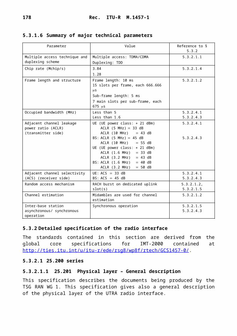
178 Rec. ITU-R M.1457-1
TABLE 21
Spreading and randomization code configurations
In line with the scheme applicable for the corresponding terrestrial radio interface, orthogonal variable spreading factor (OVSF) codes based on a length 128 bits Walsh-Hadamard code set for the 1.920 Mchip/s option and on a length 256 bits Walsh-Hadamard code set for the 3.840 Mchip/s option are proposed.
Forward link
The generic form of the forward link spreader and modulator is shown in Fig. 64. Except for the common pilot channel (PI-CCPCH), different configurations of spreading and randomization codes may be applied. Since the same randomization is applied to all simultaneously transmitted forward link channels, summation is prior to randomization.
It is proposed to use either QPSK or dual BPSK and real randomization for all DPCH and CPCH. Normally, a multitude of code channels is simultaneously transmitted on the forward link that results in a circular I/Q amplitude distribution in any case. Thus, real randomization is adequate requiring minimum complexity.
The use of dual BPSK would reduce the number of orthogonal code channels to one half, since different spreading codes are applied to the I- and Q-branch. Single spreading code dual BPSK with I/Q independent randomization represents a way to avoid the above code-book limitation at the expenses of an increased sensitivity to carrier phase errors.
Dual BPSK with real randomization is used for the synchronization burst (HP-CCPCH). The PI-CCPCH is mapped on spreading code No. 0 which is the all 1-sequence. The PI-CCPCH data is simply an endless sequence of 1 s, interrupted in those slots where the synchronization burst is transmitted. Thus, the PI-CCPCH is the randomization code itself.
Return link
The generic form of the return link spreader and modulator is shown in Fig. 65. Different configurations of spreading and randomization codes may be applied as on the forward link.
It is proposed to use either QPSK or dual BPSK data modulation both with complex randomization for DPCH. The use of orthogonal dual BPSK would reduce the number of code channels to one
Data modulation
Spreadingcodes Randomization codes Remarks
QPSK cs,m cs,m–1 cr,n cr,n–3, cr,n–1 cr,n–2 0 Real randomization
QPSK cs,m cs,m–1 cr,n cr,n–2 cr,n–1 cr,n–3 Complex randomization
Dual BPSK cs,m cs,m–1 cr,n cr,n–3, cr,n–1 cr,n–2 0 Different randomization on I- and Q-branch
Dual BPSK cs,m cs,m–1 cr,n cr,n–3, cr,n–1 cr,n–2 0 Real randomization
Dual BPSK cs,m cs,m–1 cr,n cr,n–2 cr,n–1 cr,n–3 Complex randomization

Rec. ITU-R M.1457-1 179
half. Dual BPSK with I/Q independent spreading (without code channel reduction) can be considered when code-book size is an issue. The more robust dual BPSK with complex random-ization is proposed for the random access burst (PRACH).
In contrast to the forward link, /4-QPSK spreading modulation is proposed in order to reduce envelope fluctuations. Optionally, pre-compensated frequency modulation (PFM) can be envisaged. PFM is a constant envelope modulation technique which can be designed to work with a standard Nyquist-filtered /4-QPSK receiver. PFM represents a trade-off between adjacent channel (frequency band) interference (ACI), code channel cross talk and BER-performance in AWGN conditions.
1457-65
+
+
FIGURE 65Return link generic spreader and modulator
(rates indicated refer to the 1.920 Mchip/s option and a spreading factor of 32)
Split
IQ
Cr,n
Cr,n–1
Cr,n–2
Cr,n–3
60 kdibit/s
60 k
bit/s
DPCHand
PRACH
1.92 Mchip/s
Genericrandomization
SRRCfilter
IQ
Spreading
Cs,m–1
Spreading
Q
I
Cs,m
CPMapprox.
/4–QPSK
System time and frequency reference
It is assumed that system time and frequency reference is virtually located in the satellite. This means, that the signals emitted by the satellite correspond to the nominal frequencies and timing. In case of a transparent transponder, the LES offsets the transmit times, frequencies, chip rates etc. of its feeder uplink so that the signals arrive at the intended satellite in synchronism with the nominal system time and frequency. Beam specific time shifts and Doppler pre-compensation may be additionally applied for the service links. For the return link it is assumed that the LES controls
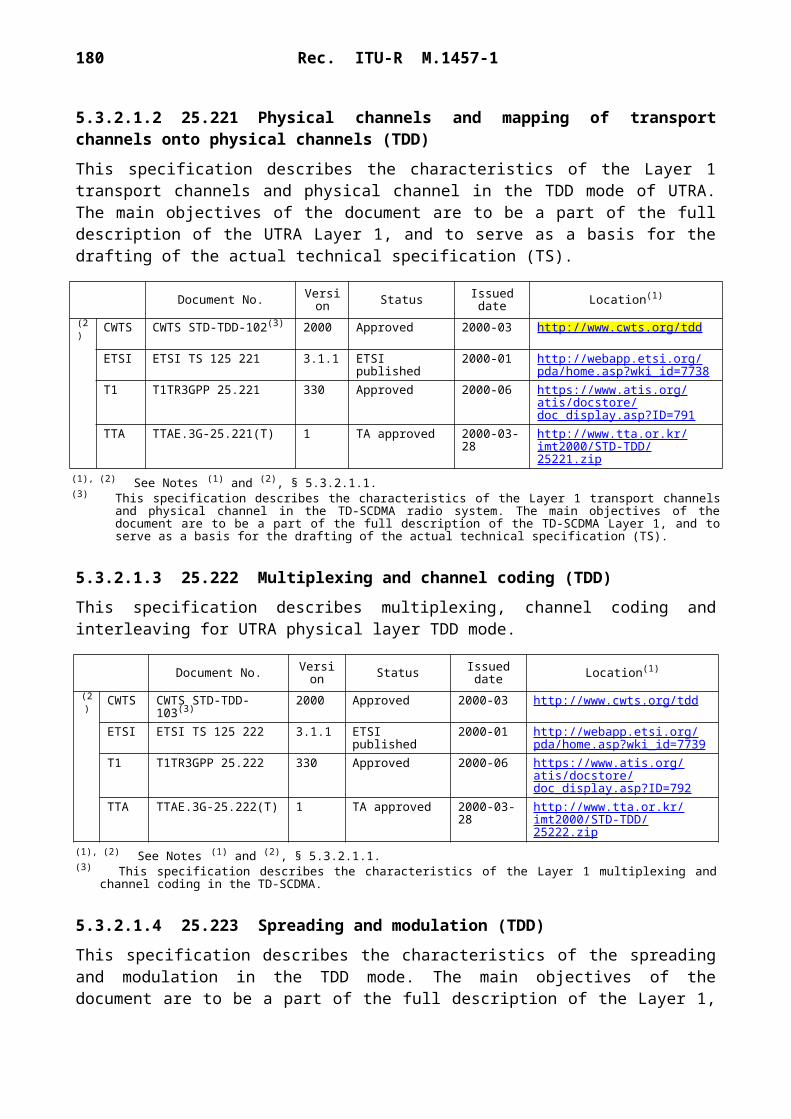
180 Rec. ITU-R M.1457-1
timing of the individual MTs such that the return link signals arrive at the intended satellite in quasi-synchronism with the nominal system time and frequency. Beam specific time shifts and frequency offsets may be applied additionally for the service return links.
The feeder downlink needs no specification in this context, since feeder propagation time varies for all beams exactly in the same manner.
Intra-satellite inter-beam synchronization
It is proposed to keep transmit times (frame structure) in all beams of the same satellite aligned. There will be small intentional and fixed time offsets in the order of a few chip periods in order to permit reuse of the same randomization code in all beams of the same satellite.
Time offsets will also be required for the return link frame structure of signals arriving at the satellite from different beams, if the same randomization code shall be used for all beams of a satellite. The same time offsets are proposed for the return link frame structure. The LES controls the MTs in a manner such that the above offsets occur at the LES receiver.
In general, there will be a fixed offset between the forward and return link frame structure.
System-wide inter-satellite synchronization
It is proposed to maintain time synchronism between all satellites belonging to the same SRAN. This means transmissions from different satellites are aligned to one another with respect to the frame structure within an accuracy in the order of a ms. In case of transparent payloads and no inter-satellite links, the system-wide synchronization may be maintained by the LESs inter-connected via a terrestrial network. Time alignment limits frame timing differences between pairs of satellites to the minimum possible. It is believed that this is advantageous for satellite path diversity and handover.
Randomization codes assignment
The purpose of the overlaid randomization of the spreading code is to make adjacent beam and inter-satellite interference appear more noise like in any situation at any time. The following generic randomization codes assignment approach is proposed:– One specific and one common randomization code sequence (real randomization) is
assigned to each satellite belonging to the same SRAN to be used on the forward link.– A specific pair of randomization codes (complex randomization) is assigned to each
satellite belonging to the same SRAN to be used on the return link.– The specific forward link randomization code is unique in the SRAN and is applied to all
forward link transmissions (except the synchronization burst) of all beams of the same satellite.
– The specific pair of return link codes is unique in the SRAN and is applied to all quasi-synchronous and asynchronous return link transmissions of all beams of the same satellite.
– The common code is applied to the forward link synchronization bursts (HP-CCPCH) of all beams of all satellites belonging to the same SRAN.
– The start of the specific and common randomization code refers to the first chip in slot No. 1 of frame No. 0 for both forward link synchronous and return link quasi-synchronous

Rec. ITU-R M.1457-1 181
traffic. Clocking of the randomization code is continued through any period of HP-CCPCH transmission on the forward link or asynchronous traffic frame on the return link where quasi-synchronous traffic is interrupted.
– In case of asynchronous traffic, the start of the randomization code sequences of the specific pair refers to the first chip of the random access burst.
The use of a common randomization code for the synchronization bursts simplifies forward link acquisition and allows decoding of the HP-CCPCH with minimum system information. Accidental interference de-randomization in case of HP-CCPCH reception is unavoidable with this approach. In order to lower the probability of acquisition failures or message losses in the delay co-incidence zones of a multiple satellite scenario, it is proposed to artificially vary the power of the synchronization bursts transmitted by the different satellites by approximately 6 dB in a manner such that only one of the serving satellites transmits at full power at a time. Power variation would be applied only in those beams covering the delay co-incidence zones.
Forward link acquisition and synchronization
The following forward link acquisition and synchronization procedure is proposed:– The MES initially acquires the forward link synchronization (time and frequency) by using
the periodic SWs transmitted in slot No. 1 of frame No. 0. The spread SW has a length of 32 30 960 chips (referred to the half rate option) and is common to all beams and satellites.
– If several SWs from different beams or satellites are detected, it chooses the one associated with the largest correlation peak to establish frequency, frame, symbol and chip synchronization.
– The MES uses the common pilot channel (PI-CCPCH) to extract the randomization code unique to the particular satellite by correlating the receive signal against all possible randomization sequences used in the SRAN.
– The MES attempts to further improve time and frequency synchronization using the PI-CCPCH.
– The MES reads the BCCH transmitted on a primary CCPCH in frame No. 0 to acquire all relevant high level synchronization and system information.
Return link synchronization acquisition
The following procedure is proposed for initial access and the return link synchronization acquisition and tracking:– The MES is allowed to access the LES only after having successfully established forward
link synchronization.– The MES reads the information about the instantaneous Doppler and time delay at the beam
centre point broadcast by the LES in frame No. 0.– The MES applies Doppler pre-compensation and timing advance, such that the random
access burst is received with minimum Doppler shift and timing error at the satellite. The MES therefore computes frequency pre-compensation and burst timing to be applied on the return link using information gathered on the forward link.

182 Rec. ITU-R M.1457-1
– The MES transmits the pre-compensated random access burst in frame No. 0 at the computed time instance. (The computed timing of the random access bursts may be additionally slightly randomized to avoid interference hot spots in the asynchronous traffic frame. However, these offsets would have to be indicated in the content of the random access burst.)
– If the LES has successfully captured the random access burst, it estimates time and frequency (measures residual timing and Doppler errors) and sends a channel assignment, as well as timing and frequency corrections to the MES using a CCPCH.
– Upon successful reception of the forward link message, the MES corrects its Doppler pre-compensation and chip timing and starts to transmit bursts in the assigned time slots within the quasi-synchronous traffic frames. The return link transmission may now be considered as quasi-synchronous to other traffic arriving at the LES. The return link may be considered as fully Doppler precompensated with respect to carrier frequency and chip clock.
– The MES continuously tracks the forward link carrier frequency and chip timing and corrects return link carrier frequency and chip timing upon reception of TFC commands continuously sent by the LES.
Recognizing that the precise synchronization required may occasionally be lost (e.g. caused by shadowing), a reacquisition procedure is also defined in order to quickly restore synchronization.
A loss of synchronization may be indicated at the LES or the MES by the fact that the BER measured over a number of received bursts exceeds a certain threshold. In case of synchronization loss the LES may initiate a reacquisition procedure. The reacquisition procedure is similar to the forward and return link acquisition procedure and is proposed as follows: – The LES requests a reacquisition using the dedicated logical control channel soon after it
has lost return link synchronization.– On reception of the reacquisition request or on local synchronization loss indication, the
MES immediately stops transmitting traffic and, if necessary, tries to reacquire forward link synchronization (the use of the common pilot may be sufficient for this purpose).
– In any case, the MES sends a reacquisition message only upon request by the LES using the random access burst. (Since timing uncertainty may be assumed to be smaller compared to the initial access case, special portions close to the edges of the asynchronous traffic frame having lower congestion may be used for this purpose.)
– After having restored full synchronization, traffic transmission is continued. The LES continues to send TFC commands to track the return link synchronization.
The quasi-synchronous W-C/TDMA return link
The advantage of a quasi-synchronous return link is that intra-beam interference is kept at a minimum, thus, allowing more inter-beam or inter-satellite interference. Its drawback is the need for precise timing control by the LES. Considering multi-satellite path diversity, only a portion of the MES population will be synchronized to one satellite (those which are assigned to that satellite by the SRAN). The return link signals of the remaining MESs, assigned to different satellites, would have to be received asynchronously.

Rec. ITU-R M.1457-1 183
FDD/TDD mode operation
The W-C/TDMA scheme proposed intends to support terminals operating in frequency/time division duplex mode. A pure TDD mode using the same carrier frequency in both transmit directions as proposed by ETSI for the terrestrial component is not considered here.
A MES operating in frequency/time division transmits and receives signals in separate time periods and on separate carrier frequencies but never at the same time. Such MESs require simpler diplexers at the antenna port.
In contrast to terrestrial networks, for satellites in non-geostationary orbit, the propagation time may significantly vary inside the footprint of a beam during a connection. The LES controls return link timing such that the frame timing of the signals arriving at the satellite is maintained at a beam specific offset.
In general, there will also be an unknown but fixed offset between the forward and return link frame structure of the same beam. While a fixed return link timing is maintained at the satellite (LES), the timing of the return link frames continuously drifts against the forward link for an observer at the MES when the path length changes. During the time a MES dwells in the footprint of the same beam, the frame offset may vary up to approximately 12 ms, depending on the satellite system. The relative frame drift in a MES operating in FDD/TDD implies the requirement of slot reassignments from time to time, in order to prevent a transmit/receive conflict. The FDD/TDD mode is mainly suited for hand-held terminals.
6.3.2.2.3 Terminal features
W-C/TDMA supports four MES classes: hand-held (H), vehicular (V), transportable (T) and fixed (F). In Table 22 the terminal feature to terminal classes are mapped.
TABLE 22
Bearer services
6.3.2.3 RF specifications
6.3.2.3.1 Satellite station
The satellite station RF specifications depend on the actual space segment architecture.
Bearer data rate (kbit/s) Supported QoS MES class
1.2 10–6 H,V,T,F
2.4 10–3, 10–5, 10–6 H,V,T,F
4.8 10–3, 10–5, 10–6 H,V,T,F
9.6 10–3, 10–5, 10–6 H,V,T,F
16 10–3, 10–5, 10–6 H,V,T,F
32 10–3, 10–5, 10–6 V,T,F
64 10–5, 10–6 V,T,F
144 10–5, 10–6 T,F

184 Rec. ITU-R M.1457-1
6.3.2.3.2 MES
In Table 23 the RF specifications for the different MES classes are reported.
TABLE 23
MES RF specifications
6.3.2.4 Baseband specifications
In Table 24 the overall W-C/TDMA baseband characteristics are summarized.
RF parameterMES class
H V T
Channel bandwidth (kHz) 2 350(1), 4 700(2)
2 350(1), 4 700(2)
2 350(1), 4 700(2)
Uplink frequency stability (ppm) 3 3 3
Downlink frequency stability (ppm) 0.5 0.5 0.5
Maximum e.i.r.p. (dBW) 8.0(3), 12.0(4) 11.0(3), 18.0(4) 20.0(3), 20.0(4)
Average e.i.r.p. per channel (dBW) (5) (5) (5)
Antenna gain (dBi) 2.0 2.0(6), 8.0(7) 4.0(6), 25.0(7)
Power control range (dB) 20.0 20.0 20.0
Power control step (dB) 0.2/1 0.2/1 0.2/1
Power control rate (Hz) 50 100 50 100 50 100
Transmit/receive isolation (dB) 169 169 169
G/T (dB/K) – 23.0(6), – 22.0(7)
– 23.5(6), – 20.0(7)
– 23.5(6), – 20.0(7)
Doppler shift compensation Yes Yes Not applicable
Mobility restriction (maximum speed (km/h))
250(1), 500(2) 250(1), 500(2) Not applicable
(1) At 1.920 Mchip/s.(2) At 3.840 Mchip/s.(3) FDD/TDD mode.(4) FDD mode.(5) Depending on the satellite station characteristics. (6) Typical value for LEO constellation.(7) Typical value for GEO constellation

Rec. ITU-R M.1457-1 185
TABLE 24
Baseband characteristics
6.3.2.5 Detailed specifications
The W-C/TDMA radio interface detailed specification is based on the following set of documents:– Physical layer: the most recent version of the W-C/TDMA documents derived from the
25.200 series (see Note 1).– Protocols: most recent versions of the 25.300 draft specifications (see Note 2).
BB-1 Multiple accessBB-1.1 Technique Forward link:
Hybrid wideband Orthogonal CDM/TDM (W-O-C/TDM)
Return link:Hybrid wideband Quasi-synchronous quasi-orthogonal CDMA/TDMA(W-QS-QO-C/TDMA)
BB-1.2 Chip rate 3.840 Mchip/s or
1.920 Mchip/sBB-1.3 Time slots 8 time slots per frame
BB-2 Modulation type – QPSK or dual-code BPSK in the uplink
– QPSK or BPSK (low data rate) in the downlink
BB-3 Dynamic channel allocation (yes/no) NoBB-4 Duplex method (e.g. FDD, TDD) FDD or FDD/TDDBB-5 Forward error correction – Standard quality: convolutional coding
with code rate 1/3 or 1/2 constraint length k 9. Variable puncturing repetition to match the required info rate.
– High quality concatenated RS code over GF(28), concatenated with inner convolutional code with rate 1/3 or 1/2, constraint length k 9.Turbo coder as option
BB-6 Interleaving – Interleaving on a single burst basis (default).
– Interleaving on a multiple burst basis (optional)
BB-7 Synchronization between satellites required – Synchronization between LESs working on the same channel of different satellites is required.
– Synchronization between LESs working on different channels of the same satellite is not required

186 Rec. ITU-R M.1457-1
NOTE 1 – This set of detailed specifications is presently being elaborated inside the ETSI TC-SES S-UMTS Working Group among the family of the voluntary standards for IMT-2000 satellite radio interface. This specification will also provide a general description of the physical layer of the W-C/TDMA air interface.NOTE 2 – As developed within the 3GPP RAN TSG. These documents can be found on: http://www.3gpp.org/TSG/RAN.htm. This specification describes the documents being produced by the 3GPP TSG RAN WG 4.
6.3.3 Satellite radio interface C specifications
The SAT-CDMA is a satellite radio interface to provide the various advanced mobile telecommu-nications services defined for the IMT-2000 satellite environment with maximum data rate, 144 kbit/s.
This system includes the satellite constellation which comprises 48 satellites in LEO for the global international communications.
The major technical scheme in SAT-CDMA is wideband code division multiple access (W-CDMA) whose chip rate is 3.84 Mchip/s.
This system will be developed to obtain more commonality with the IMT-2000 terrestrial component.
6.3.3.1 Architectural description
6.3.3.1.1 Constellation
The SAT-CDMA satellite constellation comprises 48 satellites in 1 600 km LEO. In order to get high elevation angle, economical design of satellite constellation, high data rate services, low power of MESs and satellites, and reasonable radiation dose, LEO satellites with 1 600 km altitude is assumed to be reasonable. The satellites are arranged in 8 orbital planes with 54° inclination. Each orbital plane comprises 6 equally spaced satellites. Satellites complete an orbit every 118.2 min. The configuration of satellite constellation enables to cover service areas between 69 S latitude and 69 N latitude with 15 minimum elevation angle for user links. The minimum elevation angle for feeder links is 10, and the links for inter-satellites are available. The summary of the parameters determined for the configuration is described in Table 25.
TABLE 25
Configuration of satellite constellation
Figure 66 shows user link coverage for satellites when the minimum elevation angle is 15. The minimum elevation angle sustained in the dense population area ranging 30° to 60° latitude is above 20° and the average elevation angle is above 40° in this area as shown in Fig. 67.
Orbit configuration LEO
Orbit altitude (km) 1 600
Orbit inclination (degrees) 54
Number of orbit planes 8
Number of satellites per orbit plane 6
Phase offset between adjacent orbit satellite (degrees) 7.5
Orbit period (min) 118.2
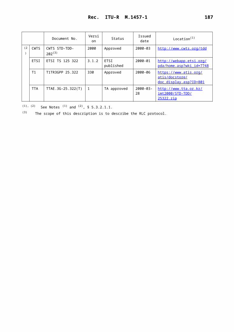
Rec. ITU-R M.1457-1 187
14
57-6
6
FIG
UR
E 66
The
cov
erag
e ar
ea u
ser
link
for
sate
llite
s with
min
imum
ele
vatio
n an
gle
of 1
5°

188 Rec. ITU-R M.1457-1
1457-67
0 10 20 30 40 50 60 70 800
10
20
30
40
50
60
FIGURE 67Minimum and average elevation angle distributions
as a function of latitude
Latitude (degrees)
Elev
atio
n an
gle
(deg
rees
)
AverageMinimum
Figure 68 displays the percentage of the satellite-view time in terms of the number of satellites (1-4) as latitude increases, showing that the minimum elevation angle is 15, the percentage of concurrent access to more than two satellites is more than 98% in the areas of latitude between 30 and 50.
1457-68
0 10 20 30 40 50 60 70 800
1020304050
100
60708090
FIGURE 68Percentage of time of visible satellites with
minimum elevation angle above 15°
Latitude (degrees)
Perc
enta
ge o
f vie
w ti
me
1234

Rec. ITU-R M.1457-1 189
6.3.3.1.2 Satellites
Each satellite provides the mobile link coverage for user terminal's through a set of 37 fixed spot beams with overlapping coverage. Figure 69 shows a set of spot-beam pattern obtained from a satellite whose radius is about 2 721.4 km. The diameter of each beam is described in Table 26. It takes about 16 min to path through a satellite coverage.
1457-69
1
2
3
4
4A
4A3A
FIGURE 69Spot-beam pattern of one satellite
TABLE 26
Spot beam size
Spot beam type Spot beam size (km)
1 519.62 584.6
3A 763.83 893.14 1 310.1
4A 1 654.0
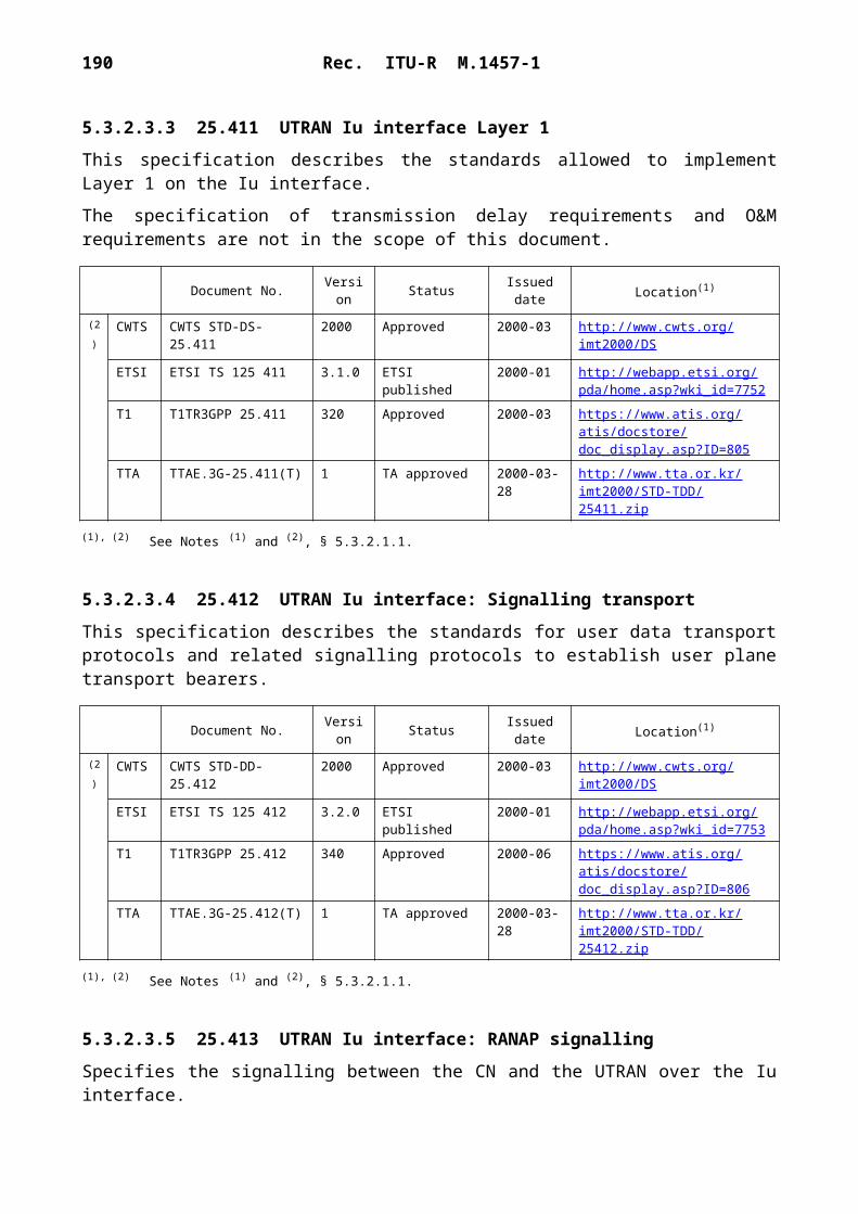
190 Rec. ITU-R M.1457-1
1457-70
0 1 000 2 000 3 000
90
80
70
60
50
40
30
20
10
0
Distance from Nadir along ground track on Earth (km)
Elev
atio
n an
gle
(deg
rees
)
Beam 4A
Beam 4
Beam 3
Beam 3A
Beam 2
Beam 1
FIGURE 70Spot beam position from Nadir on Earth and provided elevation angle
6.3.3.2 System description
6.3.3.2.1 Service features
6.3.3.2.1.1 Basic bearer services
Basic bearer services to be supported by SAT-CDMA include voice and data communications in which data rates are from 2.4 kbit/s to 64 kbit/s.
6.3.3.2.1.2 Packet data services
Packet data services will be provided at the data rates which are from 2.4 kbit/s to 144 kbit/s.
6.3.3.2.1.3 Teleservices
Teleservices include speech transmission such as emergency calls, short message service, facsimile transmission, video telephony service, paging service, etc.
6.3.3.2.1.4 Deep paging service
Deep paging service will be provided for contacting the mobile terminal user located in areas such as deep space in buildings where normal services cannot be provided.
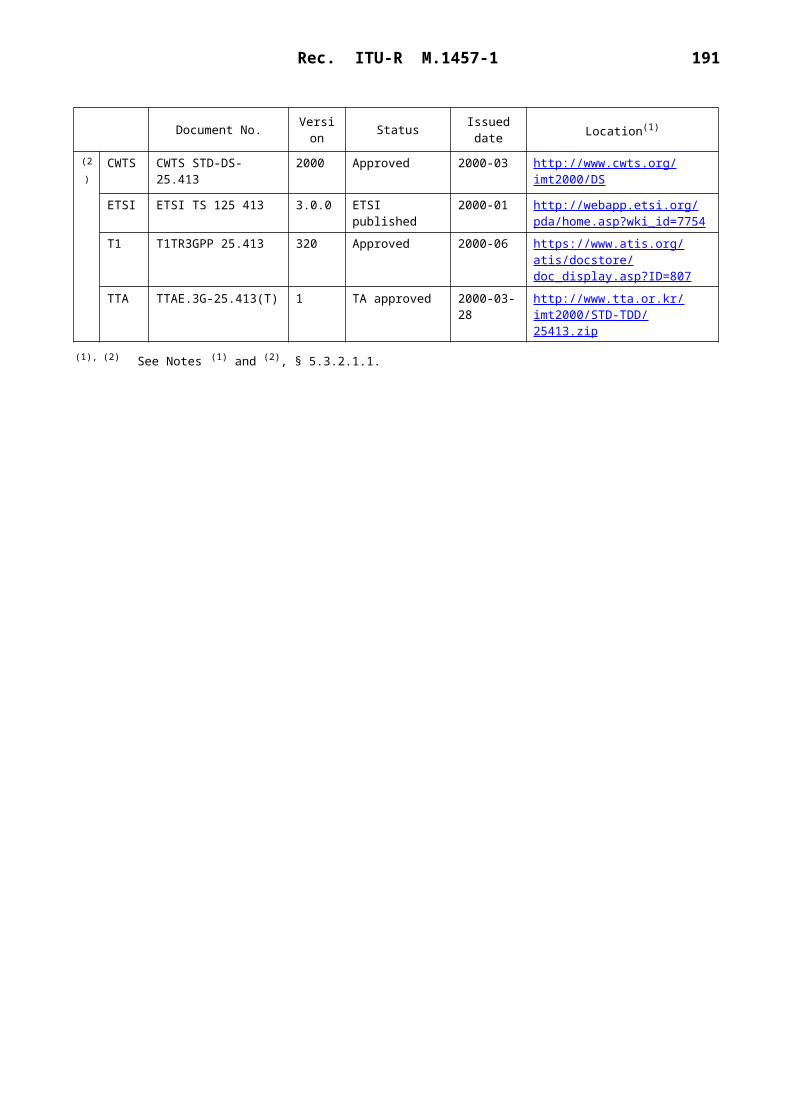
Rec. ITU-R M.1457-1 191
6.3.3.2.2 System features
The SAT-CDMA system comprises three elements: space segment, user segment, and ground segment. Figure 71 illustrates the system architecture.
1457-71
ETT GCC SCC
HLRVLR
Hand-held
Transportable
Vehicular
FixedUser segment
Ground segment
Space segment
Terrestrial network
FIGURE 71System architecture
Tracking andcontrol unit
The space segment includes the satellite constellation which comprises 48 satellites in 1 600 km LEO. The satellites are arranged in 8 orbital planes with 54° inclination. Each orbital plane comprises 6 equally spaced satellites. Satellites complete an orbit every 118.2 min.
The satellite payload consists of transponders with on-board processing units and provides the mobile links for user terminals at 2.5 GHz band, the feeder links for gateways at 4/6 GHz band and the inter-satellite links at 60 GHz band.
The ground segment comprises LES, satellite control centres (SCC), and ground control centre (GCC).
6.3.3.2.3 Terminal features
In user terminal types, there are hand-held units, transportable units, vehicular units, and fixed units.
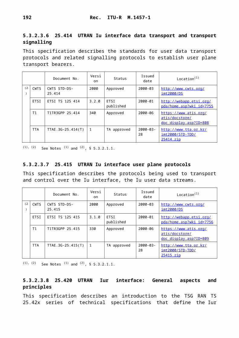
192 Rec. ITU-R M.1457-1
TABLE 27
Mobility restrictions for each terminal type
6.3.3.2.4 Handover
The SAT-CDMA will support handover of communications from one satellite radio channel to another. The handover strategy is mobile-assisted network-decided handover.
6.3.3.2.4.1 Inter-beam handover
This is required when the MES moves from the coverage of one beam to another due to MES or satellite movement. MES monitors the pilot signal levels from adjacent beams and reports to the network pilots crossing or above a given set of thresholds. Based on this information and the knowledge of satellite ephemeris, the network may decide to transmit the same information through two different beams and orders the MES to demodulate the additional signals. Coherent combining of the different signal is performed in the MES by maximum ratio combining (MRC) technique. As soon as the network obtains confirmation from the MES that the new signal is received, it releases the old channel.
6.3.3.2.4.2 Inter-satellite handover
Inter-satellite handover is required when the MES and LES are both in the coverage overlap area of two more satellites and communication has to be transferred from one satellite to another to keep continuity of connection from MES to LES and to path diversity. MES has two more resources allocated on different satellites and monitors the pilot signal levels from adjacent satellites and reports to the network. Based on this information and the knowledge of satellite ephemeris, the network may decide to transmit the same information through two more different satellites and orders the MES to demodulate the additional signals. In this case satellite path diversity is exploited. When visibility of the first satellite is lost inter-satellite handover is required, and then the first channel may be released after the new satellite has been acquired.
6.3.3.2.4.3 Inter-LES handover
In the event that a satellite handover is required but the new satellite is not in contact with the same LES as the old satellite a simultaneous LES-to-LES handover is required.
The inter-LES handover shall be negotiated between the LES. The new LES start transmitting its carrier toward the MES that is simultaneously ordered by the old LES to search for the new LES signal. When the old LES obtains confirmation from the MES that the new signal is received from the new one, the old LES stops transmitting towards the MES.
Terminal typeApplied service
data rate (kbit/s)
Nominal mobility restriction
(km/h)
Hand-held 2.4-16 500Vehicular 2.4-32 500 (maximum 1 000)
Transportable 2.4-64 0Fixed 2.4-144 0

Rec. ITU-R M.1457-1 193
6.3.3.2.5 Satellite diversity
In normal situations the MES has an unobstructed view of the satellite and gets a clear direct line-of-sight signal unlike typical terrestrial links. There is also a multi-path signal reflecting off the ground and nearby objects, which makes the resulting signal a direct plus diffuse reflection Rician signal. However, this multi-path is diffuse and all reflecting from a relatively short distance away. Such multi-path cannot be resolved in a well-known way of RAKE receiver link terrestrial cellular. Fortunately, this diffuse multi-path energy is usually quite small. Despite the fact that the RAKE receiver is not effective to combat multi-path, it is nonetheless invaluable.
From the fact that there exist coverage zones by beams of at least two different satellites in the SAT-CDMA system, each satellite may be assigned to an MES receiver in the forward direction and the power of the two satellites is effectively combined by the maximal ratio combining technique.
This multiple satellite diversity plays a two-fold role. First, it reduces the probability of shadowing by increasing the chance of having at least one satellite in a clear line-of-sight. In addition, it introduces artificial multi-path, which enable use of called artificial RAKE receiver in the MES's receiver. There is a classical diversity advantage, that is, not only the mean received power increased but also the fluctuations around the mean are decreased.
6.3.3.3 RF specifications
6.3.3.3.1 User terminal
The hand-held user terminal (UT) will provide voice and low-rate data services to personal communications users.
The hand-held UT antenna has a near omnidirectional gain profile over a hemisphere. The maximum e.i.r.p. requirement is determined by user safety requirements. The G/T is determined by the need to have a near omnidirectional antenna. The maximum data bit rate to be supported by a hand-held terminal can be specified as 16 kbit/s.
Vehicle mounted terminals are physically mounted in a vehicle. The antenna is mounted outside the vehicle and where power to the terminal is supplied by physical connection to the vehicle. Hand-held and portable terminals could be used within vehicles and certain terminals may be designed to be dual mode (hand-held/vehicle mounted or portable/vehicle mounted). The vehicle can be a car, motorcycle, truck, bus, train, ship, aircraft.
The maximum data bit rate to be supported by a vehicular terminal can be specified as 32 kbit/s.
These are large heavy MS that cannot be hand carried and whose power is generally supplied from some external source. A moveable terminal may operate as a fixed terminal since it may be taken to a location and may be switched on in order to operate. The maximum data bit rate to be supported by a transportable terminal can be specified as 64 kbit/s.
These operate from a fixed location and power is usually provided by an external source. Fixed terminals may be used to allow the provision of services to fixed terminal equipment and to connect private branch exchanges (PBXs). Fixed terminals may also operate as docking station for laptop PCs.

194 Rec. ITU-R M.1457-1
TABLE 28
UT characteristics
6.3.3.3.2 Satellite
TABLE 29
Satellite information
6.3.3.3.3 Channel bandwidth
The channel bandwidth is approximately 5 MHz.
6.3.3.3.4 Power control
The pre-defined step size of power control is 0.25 dB and 1 dB. Because of the limitation of the hand-held terminal amplifier, the dynamic range of power control is expected to be less than 20 dB.
The long round trip delays (maximum 21.52 ms in the slant range of SAT-CDMA with 1 600 km altitude) could limit the action of fast closed-loop power control. However, it would be sufficient to provide one power control command (2-bit) per 10 ms frame.
6.3.3.3.5 Frequency stability
The uplink and downlink frequency stabilities are 1 and 0.1 ppm, respectively.
6.3.3.3.6 Doppler compensation
In SAT-CDMA, compensation for Doppler shift is performed simultaneously at the transmitter (pre-compensation) and at the receiver (post-compensation).
The pre-compensation is required due to the limitation of the post-compensation and mitigates the burden of the post-compensation. The Doppler shift is compensated for by controlling the transmit frequency according to the prediction from the knowledge of the positions of the transmitter and the receiver as well as the position and velocity of the satellite.
Terminal type Hand-held Vehicular Transportable Fixed
Maximum e.i.r.p. (dBW) 2.0 15.8 21.0 36.0Maximum power (W) 1.0 14.8 17 20.0Antenna gain (dBi) 2.0 2.0 4.0 23.0Receiver temperature (K) 300 300 300 500G/T (dB/K) – 22.8 –22.8 –20.8 – 4.0
Nominal e.i.r.p. (dBW) 9.6Rx antenna gain (dBi) 20Noise temperature (K) 500G/T (dB/K) –7.0

Rec. ITU-R M.1457-1 195
The post-compensation requires two stages of carrier frequency recovery procedures: coarse and fine compensation.
The coarse compensation is performed simultaneously with the PN code timing acquisition since one of the two is easily resolved after the other is achieved. It is recommended to employ a two-dimensional search algorithm for the acquisition of both PN code timing and Doppler shift. It computes the spectrum of the de-spread signal using FFT and coarsely estimates the Doppler shift by detecting the frequency of the maximum signal power at the FFT output. PN code timing acquisition is performed by searching for a PN code timing for which the maximum signal power exceeds a given threshold.
For fine Doppler shift compensation, a closed-loop structure is recommended and it is recommended to employ the FFT-based frequency domain frequency detection algorithm since it minimizes the circuit complexity and power consumption when incorporated with the afore-mentioned two-dimensional search algorithm.
6.3.3.3.7 Terminal transmitter/receiver isolation
The isolation level required to independently operate the transmitter part and receiver part of the terminal may be above 110 dB.
6.3.3.3.8 Fade margin
At low elevations the signal level generally varies between – 7 dB below and 4 dB above the nominal level due to a combination of diffuse (arising from multiple reflections) and specular (arising from a single ground reflection) components. At higher elevations the variation is less. For a moving car, fade duration of 100-200 ms are typical. Occasionally fades of – 10 dB below the nominal level occur at very low elevation, (10° to 20°) particularly in a suburban environment, where specular multipath dominates. In such case an absolutely fixed user can experience fades of 10 to 20 s duration.
6.3.3.4 Baseband specifications
6.3.3.4.1 Channel structure
6.3.3.4.1.1 Transport channel
6.3.3.4.1.1.1 Common channel
Broadcast Channel (BCH)
BCH is a downlink channel for broadcasting system control information for each beam to MES.
Paging Channel (PCH)
PCH is a downlink channel used to carry control information to MES when the system does not know the location beam of the MES. The PCH is associated with physical-layer generated paging indicators, to support efficient sleep-mode procedures.
Forward Access Channel (FACH)
FACH is a downlink channel used to carry user or control information to MES. This channel is used when the system knows the location beam of the MES.

196 Rec. ITU-R M.1457-1
Downlink Shared Channel (DSCH)
DSCH is a downlink channel shared by several MESs and associated with one or several downlink DCH.
Random Access Channel (RACH)
RACH is an uplink channel used to carry user or control information from MES to LES.
6.3.3.4.1.1.2 Dedicated channel (DCH)
The DCH is a downlink or uplink channel transmitted over the entire beam or over only a part of the beam.
6.3.3.4.1.2 Physical channel
6.3.3.4.1.2.1 Downlink channel
6.3.3.4.1.2.1.1 Common pilot channel (CPICH)
The CPICH is a fixed rate (30 kbit/s, SF = 256) downlink physical channel that carries a predefined symbol sequence 1+j. Figure 72 shows the frame structure of the CPICH. There are two types of common pilot channels, the primary and secondary CPICH (S-CPICH). The primary CPICH is scrambled by the primary scrambling code and the phase reference for all other downlink physical channels. A secondary CPICH is scrambled by either the primary or a secondary scrambling code and may be the reference for the Secondary CCPCH and the downlink DPCH.
1457-72
1 radio frame Tf = 10 ms
FIGURE 72Frame structure for common pilot channel (CPICH)
Slot No. 1Slot No. 0 Slot No. i Slot No. 14
Tslot = 2 560 chips, 10 symbols
Pre-defined symbol sequence

Rec. ITU-R M.1457-1 197
6.3.3.4.1.2.1.2 Primary common control physical channel (P-CCPCH)
The P-CCPCH is a fixed rate (30 kbit/s) downlink channel used to carry the BCH. The P-CCPCH is not transmitted during the first 256 chips of each slot.
1457-73
1 radio frame Tf = 10 ms
FIGURE 73Frame structure for primary common control physical channel (P-CCPCH)
Slot No. 1Slot No. 0 Slot No. i Slot No. 14
Tslot = 2 560 chips, 20 bits
Data 18 bits(Tx OFF)
256 chips
6.3.3.4.1.2.1.3 Secondary common control physical channel (S-CCPCH)
The S-CCPCH is used to carry the PCH and the FACH. The SF may range from 4 to 256.
1457-74
1 radio frame Tf = 10 ms
FIGURE 74Frame structure for secondary common control physical channel (S-CCPCH)
Slot No. 1Slot No. 0 Slot No. i Slot No. 14
Tslot = 2 560 chips, 20 2k bits (k = 0, ..., 6)
Data TFCI Pilot
TFCI: transmit format combination indicator
6.3.3.4.1.2.1.4 Synchronization channel (SCH)
The SCH is a downlink signal used for beam search. The SCH consists of two sub-channels, the primary and secondary SCH. The 10 ms radio frames of the primary and secondary SCH are divided into 15 slots, each of length 2 560 chips. Figure 75 illustrates the structure of the SCH radio frame.
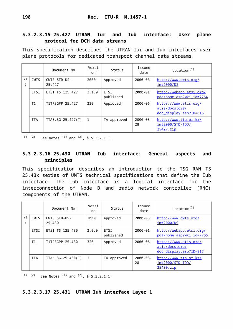
198 Rec. ITU-R M.1457-1
1457-75
.....csi,0 cs
i,1 csi,14
One 10 ms SCH radio frame
FIGURE 75Structure of synchronization channel (SCH)
Slot No. 0
256 chips
2 560 chips
Slot No. 1 Slot No. 14
cp cp cpPrimarySCH
SecondarySCH
6.3.3.4.1.2.1.5 Physical downlink shared channel (PDSCH)
The PDSCH is used to carry the DSCH.
A PDSCH is allocated on a radio frame basis to a single MES. Within one radio frame, satellite-radio access network (SRAN) may allocate different PDSCHs under the same PDSCH root channelization code to different MESs based on code multiplexing. Within the same radio frame, multiple parallel PDSCHs, with the same spreading factor, may be allocated to a single MES.
The frame and slot structure of the PDSCH are shown on Fig. 76. The spreading factors may vary from 4 to 256.
For each radio frame, each PDSCH is associated with one downlink DPCH. All relevant Layer 1 control information is transmitted on the DPCCH part of the associated DPCH.
1457-76
1 radio frame Tf = 10 ms
FIGURE 76Frame structure for physical downlink shared channel (PDSCH)
Slot No. 1Slot No. 0 Slot No. i Slot No. 14
Tslot = 2 560 chips, 20 2k bits (k = 0, ..., 6)
Data

Rec. ITU-R M.1457-1 199
6.3.3.4.1.2.1.6 Acquisition indicator channel (AICH)
The AICH is a fixed rate (SF = 256) physical channel used to carry acquisition indicators (AI). The AI corresponds to the signature on the PRACH. The phase reference for the AICH is the primary CPICH.
AICH is optional in SRAN, while AICH support is mandatory in the MES. In case the signature is not used in the PRACH preamble, AICH is not transmitted.
6.3.3.4.1.2.1.7 Paging indicator channel (PICH)
The PICH is a fixed rate (SF = 256) physical channel used to carry the paging indicators (PIs). The PICH is always associated with an S-CCPCH to which a PCH transport channel is mapped.
Figure 77 illustrates the frame structure of the PICH. One PICH radio frame of length 10 ms consists of 300 bits. Of these, 288 bits are used to carry paging indicators. The remaining 12 bits are not formally part of the PICH and shall not be transmitted.
1457-77
One radio frame (10 ms)
FIGURE 77Structure of paging indicator channel (PICH)
288 bits for paging indication 12 bits (transmission off)
6.3.3.4.1.2.1.8 Downlink dedicated physical channel (downlink DPCH)
Downlink DPCH is used to carry data generated at Layer 2 and above, i.e. the dedicated transport channel (DCH). The spreading factor may range from 4 to 512.
Within one downlink DPCH, the DCH is transmitted in time-multiplex with control information generated at Layer 1 (known pilot bits and TFCI/TPC bits).
Figure 78 shows the frame structure of the downlink DPCH. Each frame of length 10 ms is split into 15 slots, each of length Tslot = 2 560 chips. Each radio frame corresponds to one power-control period.
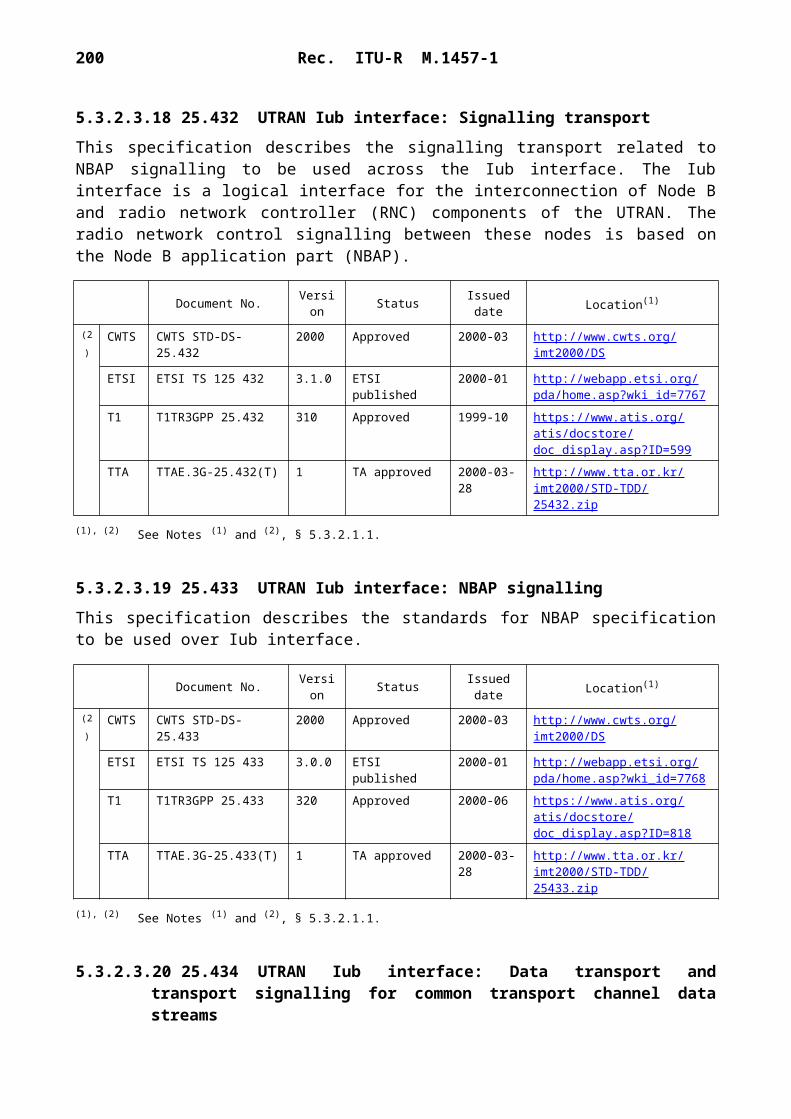
200 Rec. ITU-R M.1457-1
1457-78
1 radio frame Tf = 10 ms
FIGURE 78Frame structure of downlink DPCH
Slot No. 1Slot No. 0 Slot No. i Slot No. 14
Tslot = 2 560 chips, 10 2k bits (k = 0, ..., 7)
Data 1
DPDCH DPCCH DPDCH DPCCH
Data 2TFCI/TPC Pilot
6.3.3.4.1.2.2 Uplink channel
6.3.3.4.1.2.2.1 Physical random access channel (PRACH)
The physical random access channel is used to carry the RACH. The random-access transmission is based on a ALOHA approach. The random access transmission consists of a preamble of length Np 4 096 chips and a message of length 10 ms or 20 ms as illustrated in Fig. 79.
1457-79
. . .a0 Cpre a1 Cpre aN Cprep–2aN Cprep–1
4 096 Np chips
FIGURE 79RACH transmission
Preamble part Message part
4 096 chips
10 or 20 ms
The preamble consists of Np sub-preambles. The value of Np is provided by high layers. The sub-preamble is of length 4 096 chips and consists of repetitions of a signature. The sub-preambles are modulated by the real-valued symbols a0, a1, …, aNp – 1 shown in Fig. 79. The real-valued symbols a0, a1, …, aNp – 1 are given by 1, 1, …, –1. Using the signature is optional in the SRAN, while signature support is mandatory in the MES.
Figure 80 shows the structure of the random-access message part. The message consists of 15 slots. Each slot is comprised of two parts, a Layer 2 information data part and a Layer 1 control part.

Rec. ITU-R M.1457-1 201
1457-80
Message part radio frame TRACH = 10 ms
FIGURE 80Structure of the random access message part
Slot No. 1Slot No. 0 Slot No. i Slot No. 14
Tslot = 2 560 chips, 10 2k bits (k = 0, ..., 3)
Pilot TFCI
DataData
Control
6.3.3.4.1.2.2.2 Uplink dedicated physical channel (uplink DPCH)
The uplink DPCH consists of the uplink dedicated physical data Channel (uplink DPDCH) and the uplink dedicated physical control channel (uplink DPCCH). The DPDCH and the DPCCH are I/Q code multiplexed within each radio frame.
The DPDCH is used to carry data generated at Layer 2 and above, and the DPCCH is used to carry dedicated control information generated at Layer 1. The spreading factor may range from 4 to 256.
Figure 81 shows the frame structure of the uplink DPCH. Each radio frame of length 10 ms is split into 15 slots, each of length 2 560 chips. Each radio frame corresponds to one power-control period.
The Layer 1 control information consists of known pilot bits to support channel estimation for coherent detection, transport-format combination indicator/transmit power-control (TFCI/TPC), and an optional feedback information (FBI). The FBI bits are used to support the satellite selection diversity transmission technique requiring feedback from the MES to the SRAN.

202 Rec. ITU-R M.1457-1
1457-81
One radio frame Tf = 10 ms
FIGURE 81Frame structure of uplink DPCH
Slot No. 1Slot No. 0 Slot No. i Slot No. 14
Tslot = 2 560 chips, 10 bits
Pilot TFCI/TPC
DataDPDCH
Tslot = 2 560 chips, Ndata = 10 2k bits (k = 0, ..., 6)
DPCCH FBI
6.3.3.4.1.3 Mapping of transport channels onto physical channels
1457-82
FIGURE 82Mapping of transport channels onto physical channels
DCH Dedicated physical data channel (DPDCH) Dedicated physical control channel (DPCCH)RACH Physical random access channel (PRACH) Common pilot channel (CPICH)BCH Primary common control physical channel (P-CCPCH)FACH Secondary common control physical channel (S-CCPCH)PCH Synchronization channel (SCH)DSCH Physical downlink shared channel (PDSCH) Acquisition indicator channel (AICH) Paging indicator channel (PICH)

Rec. ITU-R M.1457-1 203
6.3.3.4.2 Channel coding and multiplexing
6.3.3.4.2.1 Processing step
The coding and multiplexing steps are shown in Fig. 83, where TrBk: transport block and DTX: discontinuous transmission.
1457-83
FIGURE 83Processing steps for transport channel (TrCH) to physical channel (left: uplink, right:downlink)
PhCH N
o. 2PhCH
No. 1
PhCH N
o. 2PhCH
No. 1
CRC attachment
TrBk concatenation/code block segmentation
Channel coding
Radio frameequalization
1st interleaving
Radio framesegmentation
Rate matching Ratematching
Radio framesegmentation
1st interleaving
Rate matching
1st insertion of DTXindication
Channel coding
TrBk concatenation/code block segmentation
CRC attachment
Ratematching
TrCH multiplexing
TrCH multiplexing
Physical channelsegmentation
2nd interleaving
Physical channelmapping
2nd insertion of DTXindication
Physical channelsegmentation
2nd interleaving
Physical channelmapping
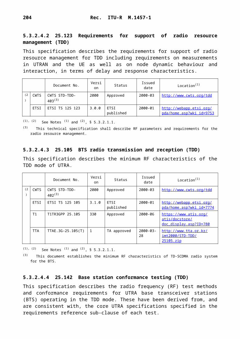
204 Rec. ITU-R M.1457-1
6.3.3.4.2.2 Error detection
Error detection is provided on transport channel blocks through a CRC. The CRC is 24, 16, 12, 8 or 0 bits and it is signalled from higher layers what CRC length that should be used for each transport channel.
The entire transport block is used to calculate the CRC parity bits for each transport block. The parity bits are generated by one of the following cyclic generator polynomials:
GCRC24(X) = X 24 + X 23 + X 6 + X 5 + X + 1;
GCRC16(X) = X 16 + X 12 + X 5 + 1;
GCRC12(X) = X 12 + X 11 + X 3 + X 2 + X + 1;
GCRC8(X) = X 8 + X 7 + X 4 + X 3 + X + 1.
6.3.3.4.2.3 Channel coding
For the channel coding in SAT-CDMA, two schemes can be applied:– Convolutional coding;– Turbo coding.
Channel coding selection is indicated by upper layers. In order to randomize transmission errors, symbol interleaving is performed further.
TABLE 30
Channel coding schemes for logical channels
6.3.3.4.2.3.1 Convolutional coding
Convolutional codes with constraint length 9 and coding rates 1/3 and 1/2 are defined.
The generator functions for the rate 1/3 code are G0 557 (OCT), G1 663 (OCT) and G2 711 (OCT).
The generator functions for the rate 1/2 code are G0 561 (OCT) and G1 753 (OCT).
Transport channel Coding scheme Coding rate
BCH
Convolutional coding
1/2PCHRACHDCH, DSCH, FACH 1/3, 1/2
Turbo coding 1/3

Rec. ITU-R M.1457-1 205
1457-84
D D D D D D D D
G2
G1
G0
FIGURE 84Rate 1/3, constraint length = 9 convolutional code generator
Input
Output 2
Output 1
Output 0
1457-85
D D D D D D D D
G1
G0
FIGURE 85Rate 1/2, constraint length = 9 convolutional code generator
Input
Output 1
Output 0
6.3.3.4.2.3.2 Turbo coding
The scheme of turbo coder is a parallel concatenated convolutional code (PCCC) with two 8-state constituent encoders and one Turbo code internal interleaver. The coding rate of turbo coder is 1/3.
The transfer function of the 8-state constituent code for PCCC is:
G(D) =
where:
g0(D) = 1 + D2 + D3
g1(D) = 1 + D + D3.

206 Rec. ITU-R M.1457-1
1457-86
D D D
D D D
FIGURE 86Rate 1/3 turbo coder generator (dotted lines apply for treillis termination only)
Input
Input turbocode internalinterleaver
output2nd constituent encoder
1st constituent encoder
Output
6.3.3.4.2.4 Interleaving
The 1st interleaver is a (M-row by N-column) block interleaver with inter-column permutations. The size of the 1st interleaver, M N is an integer multiple of transmission time interval (TTI).
The 2nd interleaver is a (M-row by N-column) block interleaver with inter-column permutations. The size of the 2nd interleaver, M N is the number of bits in one radio frame for one physical channel and the number of columns, N is 30. The inter-column permutation pattern is < 0, 20, 10, 5, 15, 25, 3, 13, 23, 8, 18, 28, 1, 11, 21, 6, 16, 26, 4, 14, 24, 19, 9, 29, 12, 2, 7, 22, 27, 17 >.
6.3.3.4.2.5 Rate matching
The number of bits on a transport channel can vary between different transmission time intervals. In uplink, bits on a transport channel are repeated or punctured to ensure that the total bit rate after transport channel multiplexing is identical to the total channel bit rate of the allocated DPCH. In downlink, the total bit rate after the transport channel multiplexing is less than or equal to the total channel bit rate given by the channelization code(s) assigned by higher layers. The transmission is interrupted if the number of bits is lower than maximum.
6.3.3.4.2.6 Transport channel multiplexing
Every 10 ms, one radio frame from each transport channel is delivered to the transport channel multiplexing. These radio frames are serially multiplexed into a coded composite transport channel.

Rec. ITU-R M.1457-1 207
6.3.3.4.3 Modulation and spreading
6.3.3.4.3.1 Uplink spreading
The spreading modulation uses orthogonal complex QPSK (OCQPSK) for uplink channels.
The spreading operation consists of two operations; short code spreading for channelization and long code spreading for scrambling.
Direct sequence spreading using the long code shall be applied to the uplink channel.
Figure 87 shows the configuration of the uplink-spreading. Channelization codes, Cch i, i 1, 2,…, N, first spread one DPCCH channel and the DPDCH channels. Then the signals are adjusted by power gain factors, Gi, added together both in I and Q branches, and multiplied by a complex scrambling code Sup,n.
If only one DPDCH is needed, only the DPDCH1 and the DPCCH are transmitted. In multi-code transmission, several DPDCHs are transmitted using I and Q branches.
1457-87
G1
G3
GN–1
G2
G4
GN
FIGURE 87Spreading for uplink DPDCH/DPCCH
DPDCH1
Cch1
Cch3
CchN–1
Cch2
Cch4
CchN
I + jQ
*j
S
Sup,N
DPDCH2
DPDCHN–2
DPCCH
DPDCH3
DPDCHN–1
The channelization codes for uplink DPCH are OVSF codes.

208 Rec. ITU-R M.1457-1
The long scrambling code is built from constituent long sequences clong,1,n and clong,2,n. The two sequences are obtained from position wise modulo 2 sum of 38 400 chip segments of two binary m-sequences xn and y. The xn sequence, which depends on the chosen scrambling sequence number n, is obtained from the m-sequence generator polynomial X 25 + X 3 + 1 and the y sequence is obtained from the generator polynomial X 25 + X 3 + X 2 + X + 1.
The configuration of long code generator for uplink is presented in Fig. 88.
1457-88
FIGURE 88Uplink long code generator
Clong,1,n
MSB LSB
Clong,2,n
6.3.3.4.3.2 Uplink modulation
The modulating chip rate is 3.84 Mchip/s.
In the uplink, the modulation is dual-channel QPSK.
The modulated DPCCH is mapped to the Q-channel, while the first DPDCH is mapped to the I channel.
Subsequently added DPDCHs are mapped alternatively to the I or Q channels.
Figure 89 shows the configuration of the uplink modulation.
1457-89
FIGURE 89Uplink modulation
Complex-valuedsequence fromspreading unit
S
I
Q
–sin(2fct)
cos(2fct)
Basebandfilter
Basebandfilter
2éme
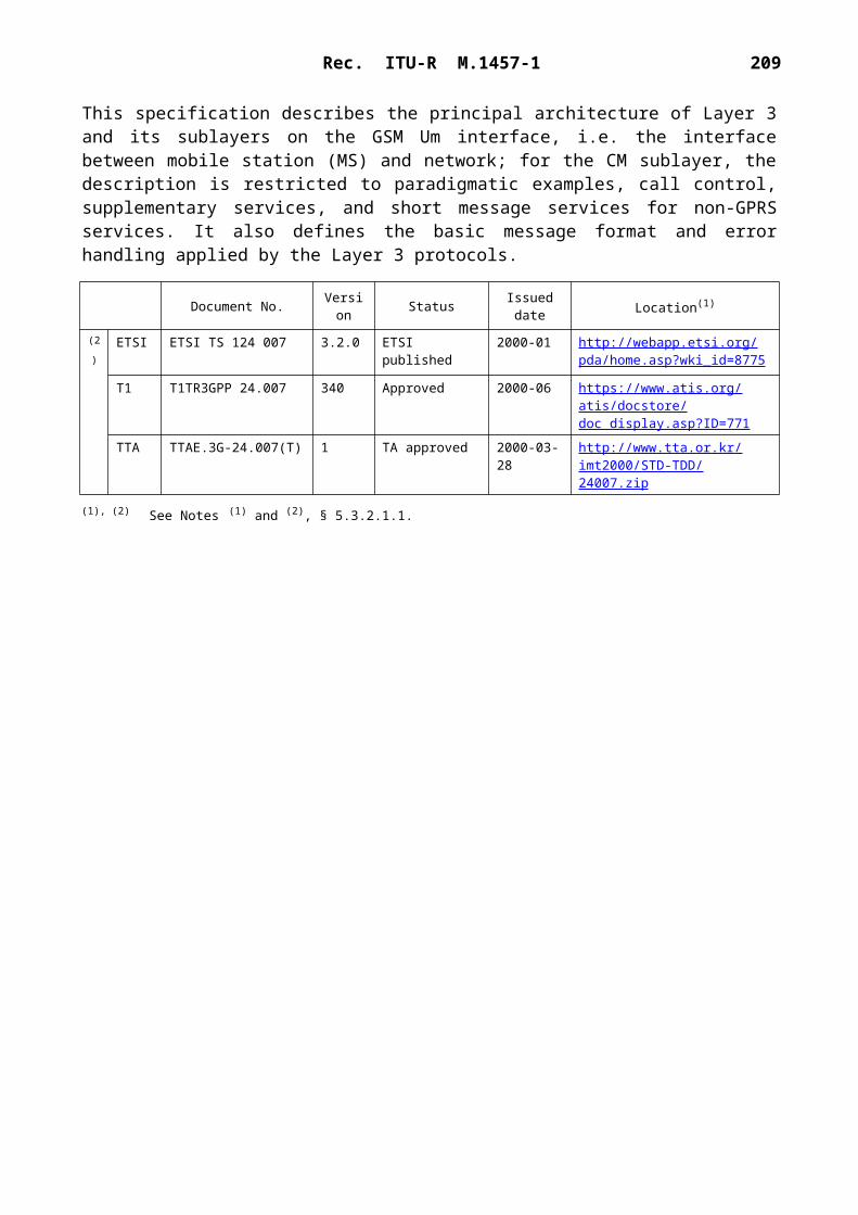
Rec. ITU-R M.1457-1 209
6.3.3.4.3.3 Downlink spreading
OCQPSK is not used in the downlink. The spreading operation consists of two operations; short code spreading for channelization and long code spreading for scrambling. Direct sequence spreading using the long code shall be applied to the downlink channel. For the downlink channel, this long code shall be periodic with period 38 400 chips. The long code length is equal to the frame length of 10 ms.
Figure 90 shows the configuration of the downlink-spreading.
1457-90
j
+
+
FIGURE 90Spreading for downlink physical channels
Anydownlinkphysicalchannel
M
I
Q
Cch1
Sdown,n1
Sdown,n2
S/P
G1
G2
Gs
Gp
P-SCH
S-SCH
The channelization code for downlink physical channels is the same OVSF codes as used in the uplink.
The scrambling code is constructed by combining two real sequences into a complex sequence. Each of the two real sequences is obtained form position wise modulo 2 sum of 38 400 chip segments of two binary m-sequences x and y. The x sequence is obtained from the generator polynomial X 18 + X 7 + 1. The y sequence is obtained from the generator polynomial X 18 + X 10 + X 7 + X 5 + 1. The initial condition for the x sequence is (00…1), where 1 is the LSB. The initial condition for the y sequence is (11…1). Fig. 91 shows the configuration of the downlink scrambling code generator.
6.3.3.4.3.4 Downlink modulation
The modulating chip rate is 3.84 Mchip/s.
In the downlink, the data modulation of DPCH is QPSK.
The modulated DPDCH and DPCCH are time-multiplexed.
Figure 92 shows the configuration of the downlink modulation.
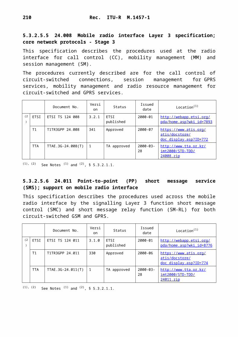
210 Rec. ITU-R M.1457-1
1457-91
FIGURE 91Downlink scrambling code generator
Q
I17 16 15 14 13 12 11 10 9 8 7 6 5 4 3 2 1 0
17 16 15 14 13 12 11 10 9 8 7 6 5 4 3 2 1 0
1457-92
FIGURE 92Downlink modulation
Complex-valuedsequence fromspreading unit
M
I
Q
–sin(2fct)
cos(2fct)
Basebandfilter
Basebandfilter
6.3.3.4.4 Procedures
6.3.3.4.4.1 Beam search
The beam search is carried out in three steps:
Step 1: MES uses the SCH's primary synchronization code to acquire slot synchronization to a beam.
Step 2: MES uses the SCH's secondary synchronization code sequences to find frame synchro-nization and identify the code group of the beam found in the first step.
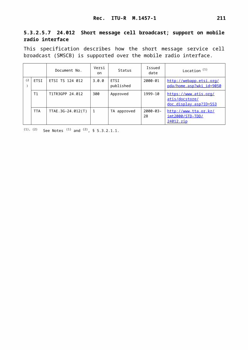
Rec. ITU-R M.1457-1 211
Step 3: MES determines the exact primary scrambling code used by the found beam. the SCH's secondary synchronization code sequences to find frame synchronization and identify the code group of the beam found in the first step.
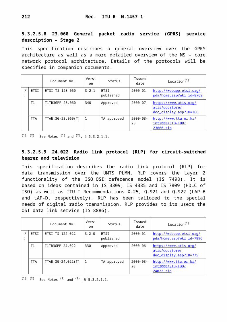
212 Rec. ITU-R M.1457-1
During the first and the second steps, a coarse frequency search and/or a differential detection technique may be required because of the carrier frequency error due to the Doppler shift.
During the second and third step, the MES can use locally stored information on satellite constellation and its position. This can reduce the beam search time.
6.3.3.4.4.2 Random access
When there is data to be transmitted, MES selects the RACH class and starts on a retransmission cycle. If the number of retransmission cycles is larger than the maximum retransmission cycles, MES stops the procedure and reports to the higher layer.
At the beginning of each retransmission cycle, MES refreshes the parameters related to RACH procedure with the recent values, including the initial transmission power. MES then decides whether to start the RACH transmission in the current frame, based on the persistence value. If the transmission is not allowed, MES repeats from the persistence check in the next frame. If the transmission is allowed, MES starts on a ramping-up retransmission period. If the number of the repeated periods is larger than the maximum ramping-up retransmissions, MES restarts on the retransmission cycle in the next frame.
During the ramping-up retransmission period, MES randomly selects a signature from the available signatures for the given RACH Class and transmits the RACH preamble and message. If no positive or negative acquisition indicator corresponding to the selected signature is detected in the downlink AICH, MES increases the transmission power by the ramping-up power step and repeats from the ramping-up retransmission period. If a negative acquisition indicator is detected in the downlink AICH, MES randomly draws a back-off delay time. After the back-off delay time, MES repeats from the retransmission cycle in the next frame.
If the positive acquisition indicator is received in the downlink AICH and the response message corresponding to the transmitted RACH message is not received in the higher layers (RLC or RRC), in the response waiting time since the last RACH transmission, MES increases the transmission power by the ramping-up power step and repeats from the ramping-up retransmission period in the next frame.
Whenever the response message corresponding to the transmitted RACH message is received in the higher layer at any time during the random access procedure, MES should stop the RACH procedure.
In the case the signatures in the RACH preamble and the downlink AICH are not used, the steps of the acquisition indicator detection are skipped.
In the transmission of the RACH preamble and message, MES may use a Doppler pre-compensation technique, based on the Doppler shift estimation on the downlink carrier.
6.3.4 Satellite radio interface D (SRI-D) Specification
SRI-D has been optimized for operation with a specific satellite system. This system consists of a constellation of satellites in MEO working with 12 LESs, which are located around the world and interconnected by a ground network. The configuration has been designed to provide coverage of

Rec. ITU-R M.1457-1 213
the entire surface of the Earth at all times. The system will route traffic from terrestrial networks through a LES, which will select a satellite through which the call will be connected to a user. Traffic from a UT will be routed via the satellite constellation to the appropriate fixed or mobile network. The system will provide users anywhere on the Earth with access to telecommunications services. SRI-D supports robust and flexible communications, both voice and data, with rates up to 38.4 kbit/s, in a spectral and power efficient manner. The large majority of UTs used with the system are expected to be truly hand-portable and capable of dual-mode (terrestrial and satellite) operation. A wide range of other UTs will be supported including vehicular, aeronautical and maritime mobile, and semi-fixed terminals.
The following sub-sections specify only those elements relevant to this Recommendation, dealing therefore primarily with worldwide compatibility and international use.
6.3.4.1 Architectural description
The ground segment employs many standard components that allow conformance of the system to terrestrial telecommunications standards. The architecture (illustrated in Fig. 93) comprises:– 12 interconnected LESs located around the world;– duplicated network management centres;– duplicated billing and administration centres.
Each LES comprises:– five antennas and associated equipment to communicate with the satellites;– mobile switching centres and registers, including HLRs and VLRs;– interconnections with terrestrial networks.
The LESs are interconnected with each other via terrestrial links, thereby building the basic platform that provides the system’s global mobile telecommunications services. Interfaces will be provided to PSTN, PLMN and data networks. However, handover is only supported within a single network. Interworking functions (IWFs) will deliver automatic roaming with other terrestrial (second and third generation) mobile networks.
6.3.4.1.1 Constellation
Table 31 summarizes the satellite constellation configuration.
Worldwide use is a key feature of IMT-2000 and the constellation described provides true global coverage whilst maintaining a high minimum elevation angle to the visible satellites, as shown in Figs. 94 and 95.
Each satellite provides radio coverage down to an elevation angle of 0° for both UTs and LESs. Figure 94 shows the percentage of time for which a number of satellites are visible as a function of latitude. For all areas of the Earth there will be two or more satellites visible for at least 90% of the time.
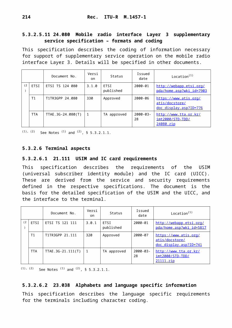
214 Rec. ITU-R M.1457-1
1457-93
v
S v
S
v
S
v
S
v
S
v
Sv
S
v
S
v
S
v
S
v
S
v
S
S
S
S
S
S
Sv
VLRPoI
IWF
IWF
IWF
IWF
IWF
IWF
IWF
IWF
IWF
IWF
IWF
IWF
Billing andadministration
Networkmanagement
FIGURE 93The ground network
Interconnection with other networks– PoI between system and interconnecting networks PSTN, PLMN and PSDN
12 LES:
Antennas Switch
PoI: Point of interconnection
Interconnecting network links
Backbone (LES-LES) network links

Rec. ITU-R M.1457-1 215
TABLE 31
Satellite constellation configuration
1457-94
1009080706050403020100
0 5 10 15 20 25 30 35 40 45 50 55 60 65 70 75 80 85 90
Latitude (degrees)
Tim
e pe
rcen
tage
FIGURE 94Typical visibility statistics for satellite constellation (10 satellites)
1 satellite2 satellites3 satellites4 satellites
Orbit type MEOOrbit altitude Nominally 10 390 kmOrbit inclination angle 45°Number of orbit planes 2Plane phasing 180Number of satellites per orbit plane 5-6In-plane satellite phasing The in-plane satellite phasing for a constellation of 10
satellites (5 satellites in each of 2 planes) is 72.If all 12 satellites are launched successfully (6 satellites in each of 2 planes) the in-plane satellite phasing is 60

216 Rec. ITU-R M.1457-1
The system is very robust to individual failures of satellite and/or LES since:– full global coverage can be maintained while there are at least four satellites in each orbit
plane;– individual LES failure will not normally result in loss of service around the LES.
Figure 95 shows the minimum and average elevation angles of the nearest satellite that gives the highest elevation amongst the visible satellites as a function of latitude. The minimum and average elevation angles exceed 20 and 40, respectively, in most areas. For regions between 20 and 50 in latitude, the constellation provides a minimum elevation angle of better than 25 and an average elevation angle of more than 50.
1457-95
9080706050403020100
0 10 20 30 40 50 60 70 80 90
Latitude (degrees)
Elev
atio
n (d
egre
es)
FIGURE 95Typical minimum and average elevation angles of the nearest satellite (10 satellites)
Minimum elevationAverage elevation
\
6.3.4.1.2 Satellites
Spacecraft
Specific features have been introduced to the satellites to meet the unique mission requirements in MEO, including:– 163 beams providing full field-of-view coverage on the service link to mobile users,
realized with separate 127 element transmit and receive direct radiating array (DRA) antennas.

Rec. ITU-R M.1457-1 217
– Beam forming and channelization of the transponders realized with digital technology that enables 490 satellite filter channels to be switched between the 163 actively generated beams. This enables the satellites to respond to traffic and interference requirements as they change through the orbit.
– An on-board self-calibration facility that monitors and, if required, corrects the service link antenna performance on-orbit. This will maintain the antenna gain and frequency reuse performance throughout the life of the spacecraft.
Communications subsystem
The payload is a fully digital design using narrow-band beam-forming, digital beam-forming and digital channelization. In the service link, the payload generates a fixed grid of 163 spot beams covering the full field-of-view from a combined transmit/receive DRA antenna fixed on the spacecraft earth panel.
The on-board digital processor is transparent in that it channelizes and routes the signals to the 163 service link spot beams and does not demodulate and regenerate the signals. 490 filter channels of 170 kHz are created in the processor and each channel can be routed to any of the 163 beams at any frequency on a 150 kHz grid within the service link 30 MHz bandwidth. Each of the 490 channels can be considered equivalent to a conventional transponder.
Channel to beam routing can be changed continuously through the orbit to enable the satellites to respond to traffic and interference demands on a preplanned, predicted basis. This also enables flexible use to be made of the available spectrum.
In addition, the digital processor forms all 163 service link spot beams by generating amplitude and phase coefficients for each of the 127 elements for each beam. The integrity of the element excitation coefficients can be verified using the on-board satellite self-calibration system, whereby an external feed on a boom senses the excitation coefficient within each element. This enables spot beam performance, both main lobe and sidelobe, to be maintained through the life of the satellite, thereby ensuring that frequency reuse between the spot beams is maintained.
Spot beams
The 163 congruent transmit and receive mobile beams per satellite are arranged in a radial circular cell pattern around the sub-satellite cell as shown in Fig. 96. The beams are electronically de-yawed to maintain the pattern relative to the spacecraft velocity vector. Beam directivity changes by about 2 dB between nadir and the edge of coverage.
The centres of the cells are defined as the centroids of the –3 dB contours of the individual beams. There are 19 beam types, numbered in order of their increasing angular distance from nadir. Each beam type has the same range of path delay, and (within 10%) the same range of Doppler.
Table 32 summarizes the nominal cell parameters.
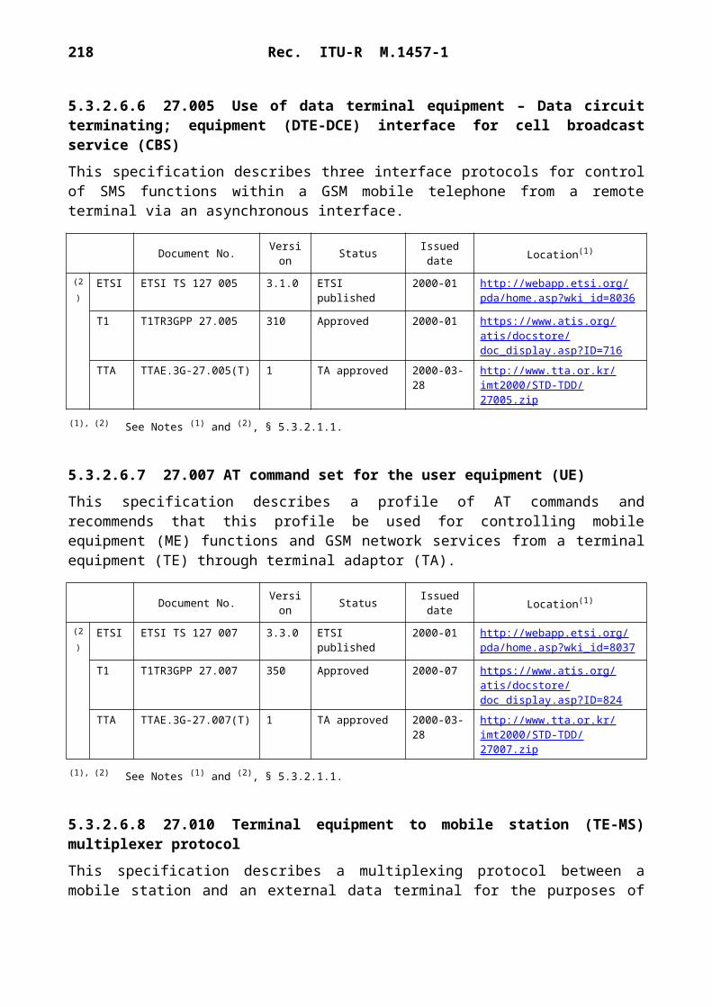
218 Rec. ITU-R M.1457-1
1457-96
–20 –10 0 10 20
20
10
0
–10
–20
= 30°
= 0°1
2
34
56
87
10
912
1115
1413
1718 19
16
E/W nadir angle (degrees)
N/S
nad
ir an
gle
(deg
rees
)
Elevation: 0°, 10°,19.5°, 31° and 47°
Beam type ID: 1-19
FIGURE 96Hexagonal lattice showing the 19 beam types
TABLE 32
Nominal cell parameters
Frequency reuse
The function of the frequency plan is to maximize the use of the mobile link spectrum while ensuring that no harmful intra-system interference occurs. The frequency plan for the whole satellite constellation is performed centrally at the network management centre.
The frequency plan defines the spectrum allocated to each beam in the constellation as a function of time in such a way that a given frequency is never available simultaneously to two beams with
Cell size 3.343Beamwidth 3.860Cell reuse 4Cell area 9.678Reuse cell area 38.714Reuse centre to centre spacing 6.686Reuse sidelobe spacing 5.015
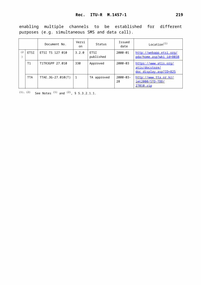
Rec. ITU-R M.1457-1 219
insufficient isolation. Beam side lobes are controlled to allow 4-cell frequency reuse within the 163 spot beam pattern. The frequency plan is adaptive to the traffic variation and the evolution of the constellation.
The frequency plan is a satellite oriented frequency assignment plan. The frequencies used in each beam remain fairly constant in the beams as the satellite moves in orbit. The mobile terminals are generally required to change frequency at beam handover.
The example frequency plan presented here has been developed for a constellation of 10 satellites in two orbital planes, each satellite having 163 fixed spot beams covering the full field-of-view with a 4-cell frequency reuse pattern as the one shown in Fig. 97. A similar frequency plan would be applicable for the 12-satellite constellation.
The mobile link spectrum is partitioned into 16 frequency blocks, as shown in Fig. 98. Eight blocks are allocated to each satellite plane: blocks 1 through 8 to plane 1 and blocks 9 through 16 to plane 2.
Within a plane of satellites, the relative position of all five satellites remains constant. The 163 beams of each satellite are divided into two groups corresponding to the leading and trailing edges of the field-of-view. As shown in Fig. 99, the leading edges of all five satellite coverages do not overlap, and the same applies to all five trailing edges. Therefore, the eight blocks nominally allocated to plane 1 are arranged into two separate 4-block sub-plans: one for the leading beams of all five satellites (blocks 1, 2, 3 and 4), the other for the trailing beams (blocks 5, 6, 7 and 8). A similar partition is done in plane 2. The frequency plan for the satellites in plane 1 is shown in Fig. 100. The leading and trailing sub-plans overlap over the central beams, as the sub-plans are designed to comprise as many beams as allowed by the beam isolation constraints.
1457-97
FIGURE 97Typical 4-cell frequency reuse pattern

220 Rec. ITU-R M.1457-1
1457-98
A1
B2
C3
D4
A5
B6
C7
D8
A9
B10
C11
D12
A13
B14
C15
D16
Beam type:Block number:
Leadingbeams
Trailingbeams
4-cell 4-cell
Overlap
Plane 1
Leadingbeams
Trailingbeams
4-cell 4-cell
Overlap
Plane 2
Sequential partitioning of the spectrum
FIGURE 98Example partitioning of the service link spectrum into frequency blocks
1457-99
FIGURE 99Example leading and trailing beam sub-plans
Leading beamsTrailing beams

Rec. ITU-R M.1457-1 221
1457-100
FIGURE 100Example frequency plan for satellites in plane 1
1.54.8
2.63.7
2.64.8
1.57.3
5.18.4
6.27.3
6.2
1.53.7
8.45.1 6.2
1.5
2.6
7.3
4.81.5
3.76.2
8.45.1
2.68.4
7.36.2
3.7
8.45.16.2
1.5
5.1
6.3.4.2 System description
6.3.4.2.1 Service features
The system supports UPT through, inter alia, service portability, which facilitates access to services expected on a home network from within a visited network, and service transparency, by which the user experiences the same look and feel, irrespective of location, through transparent service delivery.
The system can support a range of teleservices, bearer services, alternate services, supplementary services and messaging services:– Teleservices; include telephony, emergency calls, Group 3 fax (with rates up to 14.4 kbit/s).
The nominal voice coding scheme has been optimized for SRI-D. The coded rate is 4.8 kbit/s. The nominal voice codec also supports transparent DTMF sending in both forward and return directions. The radio interface can support other codecs.
– Bearer services: various data rates are supported and can be utilized dependant on application type. The channel speed can be varied according to system resources and user requirements. This functionality is not employed to compensate for transmission medium impairments. Variable rate source coding is not employed. Asymmetric transmission can be employed for data services by asymmetric allocation of TDMA slots on forward and return links. Medium data rates (up to 38.4 kbit/s using time-slot aggregation) including the

222 Rec. ITU-R M.1457-1
following, non-exhaustive list of data rates are supported (note that multiple time slots and/or multiple RF channels are used to realize data rates higher than that available from a single time slot (2.4 kbit/s before coding)):– Asynchronous transparent and non-transparent circuit-switched data: 0.3, 1.2, 2.4, 4.8,
9.6, 14.4, 19.2, 28.8 and 38.4 kbit/s.– Synchronous transparent and non-transparent circuit-switched data: 1.2, 2.4, 4.8, 9.6,
14.4, 19.2, 28.8 and 38.4 kbit/s.– Packet-switched data: The system and its radio interface are capable of supporting
packet-switched services; implementation is currently under review.– Supplementary services; include line identification services, forwarding services, call
waiting services, multi-party services, call restriction services, advice of charge services and location services.
– Messaging services; include voice messaging, fax messaging and mobile originated and mobile terminated SMS.
6.3.4.2.2 System features
Handover
Handover is supported within the system between beams of the same satellite, between beams of different satellites and between land earth stations.
UTs may be required to change frequency at handover. UT assisted handover is employed using UT measurements and controlled switching. Hard and soft handover are supported. Soft handover, implying no break on handover, is preferred whereby the handover decision is made by the UT. When soft handover is not possible, a make-before-break procedure is used.
Doppler compensation
Knowledge of the satellite’s motion and the UT's location provides the information to permit Doppler compensation. Pre-compensation limits Doppler shift to less than 1.1 kHz in the forward link and 40 Hz in the return link.
Channel allocation
On-board digital channelization enables the 490 satellite filter channels to be switched between the 163 actively generated beams. Predictive channel allocation is therefore employed to enable satellites to respond to traffic and interference requirements as practicable as they change through the orbit. It also enables flexible use to be made of the available spectrum.
Diversity
Time, space and frequency diversity are supported:– Time diversity is supported for data traffic using RLP, signalling by Layer 2 retransmission
and paging/notification/broadcast/RACH by repetition.– Space diversity is supported for traffic and signalling by allowing a UT to communicate
with the network through any of the satellites that are visible (satellite path diversity). Most of the time the system constellation provides coverage to an area via two or more diverse paths from two or more satellites, as shown in Fig. 94. The system has been designed to

Rec. ITU-R M.1457-1 223
increase the probability of a direct line-of-sight to a satellite by fully exploiting the satellite path diversity capability of the constellation for all services.
– Frequency diversity is supported for BCCH and common control channels.
The minimum number of RF receivers/antennas per UT to permit satellite path diversity is 1. The degree of improvement achieved is dependent on the underlying conditions, however since the paths are uncorrelated typically about 5 dB to 8 dB improvement is expected.
Voice activation
Voice-activated transmission is required on the forward and return links to allow satellite power savings for increased capacity on the forward link and to allow satellite and UT power savings on the return link. Voice activation is used to maximize the available return link margin and maximize the UT talk time, respectively. The voice activity factor is typically 40%.
6.3.4.2.3 Terminal features
The provision of IMT-2000 services via satellite, particularly to truly hand-portable terminals, is very demanding. Significant source coding must be employed with higher transmission powers and lower level (2 or 4 state) modulation schemes in order to attain, over the satellite link, a BER comparable to terrestrial networks. Particularly for hand-portable terminals, these requirements (coding, power and modulation which all directly impact on spectrum usage) must be balanced against the need for terminals to be similar to terrestrial terminals in terms of size, weight and battery performance.
Service will be provided to a wide range of terminal types. The large majority of UTs are expected to be capable of both satellite and terrestrial operation and, as appropriate, will support service portability, which facilitates access to services expected on a home network from within a visited network, and service transparency, by which the user experiences the same look and feel, irrespective of location, through transparent service delivery. Examples of the terminals, with their technical characteristics and services are summarized in Table 33.
TABLE 33
Examples of terminal types
Terminal Service Bit rate(kbit/s) BER(1)
Hand-heldVoice 4.8 4Data 2.4-9.6 10–5
Ruggedized transportableVoice 4.8 4Data 2.4-9.6 10–5
Private vehicleVoice 4.8 4Data 8.0-38.4 10–5
Commercial vehicleVoice 4.8 4Data 8.0-38.4 10–5
Semi-fixedVoice 4.8 4Data 8.0-38.4 10–5
(1) The BER for voice services is before error correction.

224 Rec. ITU-R M.1457-1
The technology used in these terminals is also expected to be incorporated in a wide range of other UT types including vehicular, aeronautical, and maritime mobile terminals and semi-fixed ter-minals, such as rural telephone booths and community telephones.
6.3.4.3 RF specifications
Power control
A UT will control its output as required by the network and the network will control the output power of the land earth station for each individual channel. The objective of the power control is to enable the minimum transmit power to be used by the LES, UT and satellite for each radio channel that is sufficient to maintain an acceptable received signal quality. Closed-loop power control is used for traffic channels in both the forward and reverse direction. Open-loop power control can also be used. Power control results in:– an increase in system capacity;– an increase in UT battery life;– a reduction in interference.
A power control step size of 1 dB is used, with a dynamic range of 16 dB. The number of power control cycles per second is 2 cycles. The power control bit rate is variable from 2 to 10 bits per 0.5 s per 2 paths.
Channel bandwidth, bit rate and symbol rate
The RF channel spacing is 25 kHz. The RF channel bit rate and symbol rate are dependant on the channel type and its associated modulation. Table 37 provides further information on channel types and associated modulations.
For channels employing QPSK or GMSK modulation, the RF channel bit rate is 36 kbit/s. For channels employing BPSK modulation, the RF channel bit rate is 18 kbit/s.
For channels employing QPSK or BPSK modulation, the channel symbol rate (after modulation) is 18 ksymbol/s. For channels employing GMSK modulation, the channel symbol rate (after modu-lation) is 36 ksymbol/s.
UT e.i.r.p. and G/T
Nominal values for UT e.i.r.p. and G/T for each example terminal type are given in Table 34.
TABLE 34
Nominal UT e.i.r.p. and G/T

Rec. ITU-R M.1457-1 225
Terminal Gain(dBi)
G/T(dB(K–1))
Peak e.i.r.p.(dBW)
Minimum peak e.i.r.p.(1)
(dBW)
Time average e.i.r.p.(2)
(dBW)
Hand-held 2 –23.8 7 – 9 – 4Ruggedized transportable 3.5 –21.5 7 – 9 – 4Private vehicle 3.5 –21.5 10 – 6 –1Commercial vehicle 6.5 –18.0 10 – 6 –1Semi-fixed 10.5 –14.0 10 – 6 –1
(1) Takes into account power control.(2) Time averages have been calculated assuming single slot voice use at peak e.i.r.p. with discontinuous
transmission. Power control has not been taken into account.

226 Rec. ITU-R M.1457-1
Satellite e.i.r.p. and G/T
To aid description of the satellite e.i.r.p. and G/T performance, Fig. 101 defines various ranges of satellite nadir angle (corresponding to equal surface areas on the Earth).
1457-101
Satellite coverageRange of satellite
nadir angle
0.0°-15.13°
15.13°-19.07°
19.07°-21.09°
21.09°-22.05°
22.05°-22.41°
FIGURE 101Definition of e.i.r.p. specification areas from a satellite
The service link e.i.r.p. resource can be flexibly allocated to any of the 163 spot beams by appropriate selection of the uplink (feeder link) frequency corresponding to the satellite filter channel routed to the desired spot beam. Table 35 indicates the nominal maximum e.i.r.p. in each ring if all the e.i.r.p. were directed to that ring only to the exclusion of the beams in the other rings. In realistic traffic applications, e.i.r.p. will be distributed in all rings with less e.i.r.p. than the peak for each ring.
TABLE 35
Nominal service link maximum e.i.r.p. for each ring
Ring 1 Ring 2 Ring 3 Ring 4 Ring 5
SSPA combined output power (dBW) 28.5 28.5 28.5 28.5 28.5Output losses (dB) 0.7 0.7 0.7 0.7 0.7Antenna average gain (dB) 30.6 29.6 28.9 28.7 28.2e.i.r.p. (dBW) 58.2 57.4 56.7 56.6 56.1Power robbing at worst gain setting (dB) 0.4 0.5 0.6 0.7 0.7Useful e.i.r.p. (dBW) 58.1 56.9 56.1 55.9 55.4

Rec. ITU-R M.1457-1 227
The nominal service link G/T allocation is given in Table 36 for each ring of spot beams.
TABLE 36
Nominal service link worst-case G/T for each ring
Synchronization and frequency stability
LES-LES synchronization of the bit clock is required. The 2 timing accuracy is 1 s and the external system reference is GPS.
The network controls the UT burst timing. The UT synchronizes to the forward link timing, the LES measures the offset from the expected value and any correction to be applied is sent to the UT via a control channel. The UT timing reference clock accuracy is typically 3 ppm.
The frequency stability of the satellite transmit signal is 0.5 ppm.
The UT transmit frequency is controlled by the network. The UT synchronizes to the forward link frequency, the SAN measures the offset from the expected value and any correction to be applied is sent to the UT via a control channel. The frequency stability of the UT transmission is 3 ppm (unlocked) and 0.1 ppm (locked).
Polarization
The polarization on the uplink (Earth-to-space) and downlink (space-to-Earth) is RHCP.
Frequency reuse
Typically a 4-cell frequency reuse pattern is used as the basis for the frequency plan. See § 6.3.4.1.2 for further details.
6.3.4.4 Baseband specifications
Multiple access
The system operates in an FDD mode, however there is not generally a fixed frequency relationship (duplex spacing) between the Earth-to-space and space-to-Earth frequencies used for communi-cations to and from the UTs. A combination of FDMA and TDMA is used. Each 25 kHz RF carrier supports frames of length 40 ms. Each frame supports 6 TDMA time slots, with each time slot therefore of duration ~ 6.67 ms (40/6 ms). Each time slot contains 2 guard symbols at both its start and end.
Ring 1 Ring 2 Ring 3 Ring 4 Ring 5
Average antenna gain (dB) 30.4 29.4 28.7 28.5 28.1System noise temperature (dB/K) 25.5 25.0 24.3 23.9 23.8
G/T without losses (dB(K–1)) 4.9 4.4 4.4 4.6 4.3
Losses at low processor gain (dB) 2.3 2.4 2.6 2.8 2.8
G/T at low processor gain (dB(K–1)) 2.6 2.0 1.8 1.9 1.5

228 Rec. ITU-R M.1457-1
Modulation
The modulation scheme employed depends on the channel type. Table 37 provides information on carrier types and their associated modulations.
TABLE 37
Carrier types and their associated modulations
Coding
The convolutional coding rate used depends on carrier type. Table 38 provides information on the coding rates employed.
TABLE 38
Coding rates
Soft decision decoding is used.
Carrier bit rates
Each time slot supports a bit rate of 6 kbit/s (a channel bit rate of 36 kbit/s with 6 time slots per frame). This provides for 4.8 kbit/s of data and 1.2 kbit/s of framing and in-band signalling.
For TCH, each time slot supports nominal user information bit rates of 2.4 kbit/s for data (before coding) and 4.8 kbit/s for voice (after coding).
Carrier type Modulation
Voice (TCH) QPSK (GMSK on return uplink)Data (TCH) QPSK (GMSK on return uplink)BCCH BPSKRACH BPSK (S-BPSK on return uplink)SDCCH BPSK
Carrier type Coding rate
Voice (TCH) 1/3Data (TCH) 1/2BCCH 1/2RACH 1/6SDCCH 1/4
Rec. ITU-R M.1457-1 229
For BCCH and RACH, a coded bit rate of 18 kbit/s is supported.
For associated control channels, maximum bit rates of 160 bit/s (SACCH) and 80 bit/40 ms (FACCH) are supported.
Interleaving
For voice (TCH), intra-burst interleaving is used. For data (TCH), intra-burst interleaving and interleaving over 4 bursts are used.
6.3.5 Satellite radio interface E specifications
Satellite radio interface E (SRI-E) was optimized for use with a constellation of geostationary satellites to provide worldwide coverage for multimedia terminals, in line with the objectives of IMT-2000. Although SRI-E has been optimized for the satellite environment, account has also been taken of the need for broader compatibility within the spirit and objectives of IMT-2000. The primary terminal type foreseen for use with SRI-E is a laptop or palmtop computer connected to a small, portable communications unit incorporating a directional antenna. With such terminals SRI-E can achieve information transfer rates of up to 144 kbit/s. SRI-E caters for all terminal mobilities ranging from stationary (including FWA) up to aircraft speeds.
The primary traffic objective is data, particularly for connectivity to the public Internet and to private Intranets, in support of typical applications used over these networks such as e-mail and information browsers. Traditional telecommunications services, such as voice and fax, are also supported. Although the bit rate per carrier is 144 kbit/s, higher bit rates are also possible, for semi-fixed terminals, through the aggregation of carriers. The satellites used to support SRI-E should use state-of-the-art geostationary technology, where each satellite deploys a large number of spot beams, which together cover continental sized areas and achieve frequency reuse in a manner analogous to that of terrestrial cellular systems.
A key objective in the design of SRI-E has been to make it fully independent of the services and traffic types that it carries. This is viewed as an essential characteristic for a multimedia system. At the MAC level, SRI-E closely resembles ATM, for example in its use of TDMA slots with a 48-byte payload of user data, allowing it to carry any type of traffic that can be carried over ATM. Because of this, SRI-E is not tied to the use of any particular protocols or algorithms for particular types of traffic. For example, there is no dependency on any particular voice compression technique when voice traffic is carried. It is envisaged that ITU-T Recommendation G.729 will be used, but other techniques could be used if higher quality or lower bandwidth were required, without impact on the radio interface.
6.3.5.1 Architectural description
6.3.5.1.1 Constellation
As mentioned above, SRI-E is optimized for implementation with a geostationary-satellite system. The constellation parameters are summarized in Table 39.

230 Rec. ITU-R M.1457-1
TABLE 39
Satellite constellation characteristics for SRI-E
6.3.5.1.2 Satellites
The complexity of the satellite-borne equipment expected to be used with SRI-E is at the limit of currently deployable technology. It allows the use of multiple spot beams, and it provides the RF power needed to enable the high rate information services to be delivered to small mobile terminals.
The satellite characteristics ideal for use with SRI-E are shown in Table 40.
TABLE 40
Satellite constellation characteristics for SRI-E
Satellite altitude 36 000 kmOrbit inclination angle 4.8°Number of orbit planes 1Number of satellites per orbit plane 3 for global coverageSatellite diversity method No satellite diversity is used
Number of spot beams per satellite Up to 300, depending on desired coverageConfiguration of spot beams Spot beams are assumed to be simple cones. The
configuration should be flexible and reconfigurable during system lifetime in response to evolving traffic patterns
Spot beam size Approximately 1 beam width, i.e. 800 km diameter at the sub-satellite point
Frequency reuse Frequency reuse plan is based on 7-beam clusters.In the satellite environment, frequency allocation to spot beams follows a simple, regular pattern. Frequency planning does not affect other aspects of the system, e.g. signalling, synchronization, inter-working with terrestrial networks
Service link G/T of satellite beam Average: 12 dB/KMinimum: 10 dB/K
Service link saturation e.i.r.p. of each beam Minimum: 38 dBWMaximum : 53 dBW
Service link total saturation e.i.r.p. per satellite 66 dBWSatellite e.i.r.p. per RF carrier: 38 dBW Maximum e.i.r.p.: 38 dBW
Average e.i.r.p.: 35 dBW
Rec. ITU-R M.1457-1 231
TABLE 40 (end)
6.3.5.2 System description
6.3.5.2.1 Service features
SRI-E is independent of application protocols and can support any multimedia service, subject to the upper bit rate limit, and in the satellite environment to delay. SRI-E is capable of providing multiple user services simultaneously with appropriate channel capacity assignment, e.g. simul-taneous voice and data services. The variable bit rate capability is one of the key features of SRI-E. Extra bearers can be assigned during the communication, including where necessary the use of handover to achieve the necessary capacity. Handover results in loss of a small number of slots, but the design includes a higher-layer protocol (ITU-T Recommendation V.76) which makes this transparent to multimedia applications.
The carrier user bit rate is 144 kbit/s, but SRI-E allows for higher bit rate services to high gain antennas such as could be deployed for vehicular, semi-fixed (nomadic) and FWA. SRI-E is well suited to FWA. No base stations or repeaters are required. A fixed installation may access the system directly and obtain ISDN services. Both mobile and fixed users can be accommodated with no modifications.
6.3.5.2.1.1 Capability for multimedia services
Multimedia services are different from traditional telecommunication services in a number of ways, as described in the following sections. SRI-E has been designed for this traffic, as explained under each of the topics.
Independence between transport and applications
Second-generation mobile networks have a close association between the radio transport and the characteristics of the principal application, i.e. voice traffic. For a multimedia network such a coupling is highly undesirable. Rather, a radio interface should be designed to be as general as possible and to support a wide variety of traffic, including those which have not been foreseen at present. This principle underlies the design of ATM.
Required frequency stability 1 ppmPower control Allows an average saving of around 3 dB in satellite
power; this enables a virtual doubling of traffic capacity
Power control step size 0.5 dBNumber of power control cycles per second 1Power control dynamic range 8 dBMinimum transmit power level with power control
7 dBW
Residual power variation after power control 1 dB

232 Rec. ITU-R M.1457-1
SRI-E fully supports this objective. It makes no assumption about the protocols or services to be used above it. Compatibility with terrestrial ATM (for example, the use of a 48-byte user payload) ensures that any traffic which can be carried by ATM can also be carried by SRI-E (as long as bandwidth is adequate).
Support of IP-based services
In the coming decade the Internet will assume an importance equal to that of the international telephone network, as the global backbone for information sharing and exchange as well as for real-time distribution of data. Indeed, there are those who claim that it will even usurp the role of the telephone network for carrying voice, although this claim remains contentious. In addition to the shared Internet, companies and other organizations now base their internal information sharing around Internet technology, leading to so-called Intranets and, for closed groups of users, Extranets.
Any communications technology designed to integrate with the real world of the twenty-first century must incorporate the Internet and its associated protocols as a primary mode of operation. The ability to handle this traffic with maximum efficiency will be the distinguishing criterion of successfully-deployed communications technologies.
One of the primary characteristics of Internet traffic, compared with traditional telecommunications, is its bursty nature. A user will typically require information in relatively concentrated bursts, for example when loading a web page or a form, and will then have low bandwidth requirements for a period afterwards. This is a well-known characteristic of today's network, allowing for statistical multiplexing of, typically, five times the number of users that the static bandwidth would appear to permit. Traditional networks, with their emphasis on fixed bandwidth for the duration of a call, are ill-equipped to deal with such traffic. Another characteristic of this traffic is its asymmetry. Typically the amount of data flowing in one direction (normally towards the user) exceeds that in the other direction by an order of magnitude.
SRI-E has been designed with Internet support as its primary goal. Its variable bandwidth service provides instantaneous response to changing traffic, especially towards the remote user. No renegotiation or other delay is imposed between the arrival of traffic and the assignment of corresponding bandwidth, assuming that the latter is available. Where there is contention for bandwidth (i.e. there is not enough to meet the instantaneous demand) it automatically shares what is available in an equitable fashion. Although not included in the current proposal, allowance is also made for more elaborate schemes where, for example, some calls might receive a greater share of bandwidth when contention occurs, based on a commercially priced quality of service.
The dynamic bandwidth assignment also naturally allows for asymmetrical traffic. A mixture of typical Internet users together with reverse-direction traffic, such as uploading of transaction histories or telemetry data, will automatically optimize the use of bandwidth.
Another characteristic of Internet use (including Internet-like services such as Intranets) is that users expect full-time connection, without active intervention on their part for example to make or break a call in relation to their activities. (This mode of operation is reluctantly supported by domestic dial-up users but does not occur in the corporate environment and is really an artefact of the unsuitability of the PSTN for this kind of traffic.) It is therefore desirable for an access technology to provide a low-cost mode of connection on a full-time basis, with actual bandwidth being engaged only when required in response to the traffic.

Rec. ITU-R M.1457-1 233
SRI-E provides such an option, corresponding to unassured bit rate (UBR) in ATM networks. When such a user is inactive (as determined by traffic monitoring) no radio resources are used. When they become active, i.e. when traffic is received at the base station or from the user's terminal, radio resources are allocated through a call restoration procedure.
Support for multiple concurrent calls
Multimedia traffic will frequently demand multiple calls, to the different or the same destinations and with differing quality requirements. For example, the ITU-T Recommendation H.323 standard for multimedia conferencing assumes this capability.
SRI-E supports any mixture of calls, each with its own destination and QoS, within the overall capacity limit of a channel (144 kbit/s). SRI-E automatically multiplexes calls for different ter-minals within a channel, but can dedicate a whole channel to a single terminal if required.
The handover capability is used not only to support geographic mobility but also to optimize channel usage. A terminal may start its activity with a single low-bandwidth call (e.g. voice) then add further calls until the shared capacity of the channel is no longer adequate. At this point the handover mechanism is invoked to move the terminal (or indeed another terminal) into another channel, having the required capacity. Similarly, as calls are terminated, effective use of bandwidth may require that terminals operating in different channels be compacted into a single channel, freeing resources for use elsewhere.
Support for multicast traffic
Whereas traditional telecommunications services are oriented towards point-to-point (or singlecast) traffic, with accommodation of multi-party traffic through external devices, multimedia traffic often has a multicast requirement. An obvious example is videoconferencing and videocasting, but the Internet increasingly uses multicast to provide live information feeds (the so-called push model for service distribution). Commercial traffic also often has a multicast requirement, for example for the periodic distribution of bulk data, such as price lists and catalogues, to multiple sites. Indeed, this is one of the commercial attractions of VSAT networks.
SRI-E provides for multicast traffic sources. Individual terminals can subscribe to a multicast feed using the normal signalling protocol; such feeds are identified by an address as for any other destination. Feeds can be open to all (as is typically the case for Internet sources) or can be restricted to a closed user group, more common for private feeds such as company data.
Support of location determination
It is increasingly a legal requirement on mobile systems that they be able to inform security and emergency services of the physical location of a terminal. Provision of this capability will therefore be a requirement in order to obtain an operating licence in many countries. Moreover other regulatory differences between countries, which could impact on the use of the terminal or services, require location information.
A system using SRI-E should use an independent GPS receiver to obtain accurate (100 m) position information. The signalling protocol includes the means to transmit this to the base station. If SRI-E were used in a terrestrial environment then the GPS receiver could be replaced by radio-location means.

234 Rec. ITU-R M.1457-1
6.3.5.2.1.2 Quality aspects
SRI-E does not intrinsically impose any particular voice quality. It is envisaged that ITU-T Recommendation G.729 will be used and quality will be as specified therein. Lower or higher qualities (with corresponding impact on bandwidth requirement) are possible without impact to the radio interface.
Transmission quality is one of the strengths of SRI-E, since it provides a BER which is superior to 1 10–6 under all operational conditions, with an average closer to 1 10–7. This is adequate for all multimedia applications, without further enhancement at the radio interface or interface layers. (Applications requiring higher integrity than this invariably operate their own higher-layer data integrity protocols.)
In addition, the SRI-E includes a satellite-hop data-integrity enhancement protocol, using ITU-T Recommendation V.76, to reduce the effective BER over the satellite link. This is important (but not indispensable) for Internet and similar protocols, because of the effect of retransmission on throughput and delay. This reduces the BER to negligible levels (better than 1 10–13) with only slight impact on delay.
For real-time applications, in particular voice, the BER is 1 10–6, which considerably exceeds IMT-2000 requirements.
No service quality metrics are given, since SRI-E does not impose constraints on the service protocols used. ITU-T Recommendation G.729 is envisaged as a likely candidate for toll-quality voice transmission. This meets IMT-2000 requirements.
Handover is achieved with the loss of only a single frame, which in many cases will mean only a single cell. For voice and other real-time services, this will pass unnoticed. For non real-time services, such as Internet access, the cell loss will be recovered by the ITU-T Recommendation V.76 integrity enhancement protocol, and will therefore be transparent to the application. It will appear in the same way as a transmission error, which will be statistically more common.
Variations in signal quality are dealt with through active power management rather than by reducing the quality of service as seen by the user. This is more appropriate to a multimedia environment, where applications are typically more sensitive to data errors or to the effects of error recover than is the case for traditional services such as voice.
6.3.5.2.2 System features
Gateways
Calls are directed to the satellite gateway responsible for the spot beam in which the terminal is located. This is a simple routing function. PSTN/ISDN switches can be used for this purpose, so long as suitable IN support is available to handle mobility management. All satellites in the system have to be visible from at least one gateway each. Thus, only a small number of gateways are required in the geostationary satellite environment - a minimum of one per satellite or three for a global system.

Rec. ITU-R M.1457-1 235
Network interface
SRI-E does not impose any constraints on the network interface. No additional PSTN functionality is required for ISDN or PSTN inter-working. Similarly, no constraints are placed on Internet routers. However, SRI-E can take advantage of emerging Internet features such as bandwidth reservation.
Conventional network interfaces can be used, following established standards such as ITU-T Recommendations Q.931, Q.2931 and Q.761. Satellite and mobile specific features such as handover and mobility management are not visible at the network interface.
No modifications are required to the landline network for SRI-E to pass the standard set of ISDN bearer services. All landline ISDN and other services and features are passed in the SRI-E signalling protocol, which has been designed for this purpose.
Handover/automatic radio link transfer (ALT)
Handover is only required between channels within a spot beam or between spot beams of one satellite. Handover is handled entirely within SRI-E. Handover is initiated by the MS in response to position information and signal strength measurements, or by the LES to optimize use of radio resources (e.g. to concentrate traffic into fewer channels). Thereafter, it is managed by the LES. During handover, traffic is transmitted and may be received at the LES on both channels, until confirmation is received that the MS has completed the handover and is operating on the new channel (and spot beam if handover is from one beam to another). Reconstitution of the single traffic stream occurs at the LES.
Handover results in the loss of all slots in a single frame. This is primarily due to local oscillator settling time. For voice, this means a single cell, with no audible impact, when using ITU-T Recommendation G.729. For data, the use of the higher-level data integrity protocol of ITU-T Recommendation V.76 will ensure services recover transparently from the handover without user impact.
Handover affects system complexity in two ways:– the need for additional protocol mechanisms - these affect only software and therefore do
not impact the unit terminal cost;– the need for BS channel units to be able to split and combine traffic from the old and new
radio channels during the handover - this has no impact on terminals.
Dynamic channel allocation
Frequencies can be dynamically assigned to spot beams according to traffic load. In the satellite environment, substantial variations in propagation conditions do not arise, hence SRI-E is more spectrally efficient (and more efficient in the use of critical satellite power) than is the case where wider variations need to be accommodated.
Repeaters/remote antennas
SRI-E is optimized for use in the satellite environment. Repeaters or remote antennas can be used in this environment as a means of implementing a tandem connection to a mobile or fixed (terrestrial)
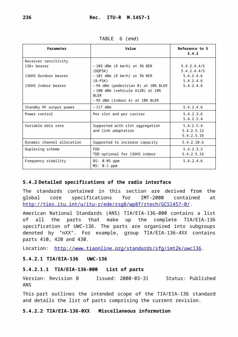
236 Rec. ITU-R M.1457-1
BS. Repeaters may be incorporated using SRI-E or other radio interfaces as depicted in Recommendation ITU-R M.687.
Power consumption
SRI-E has been designed for use in situations where access to mains power may be impossible. It therefore optimizes power consumption, allowing the greatest possible economy in both standby and operational modes. Both transmission and reception operate intermittently, as required by the traffic. Even when variable bandwidth calls (e.g. for Internet traffic) are in use, intermittent reception is used except when a burst of traffic is being received.
In standby mode, terminals do not normally transmit and the receiver needs to be active for only 0.5% of the time. While the receiver is inactive (whether in active or standby mode) all of the associated circuitry, such as DSPs, can also be powered down and receive only combined paging/synchronization bursts for approximately 0.5% of time. Active terminals receive only during slots assigned for committed bandwidth CIR, or when they are using additional bandwidth for variable bit-rate services. Thus a terminal involved in a 8 kbit/s voice call will transmit and receive for only 1/18th of the time.
Feasibility studies have shown that a target weight of 750 gm for the communication unit (plus the weight of the user's own terminal, e.g. laptop or palmtop computer) is feasible, as is an on-air battery lifetime of 2 h and a standby time well in excess of 24 h. The latter may of course be further extended if the user powers down the terminal when not in use, which is likely because of the use of computer equipment with similar power constraints.
Synchronization
To ensure accurate TDMA framing, synchronization between all system components, including LES, MS and satellite, is required to within one symbol time (10 s). Synchronization occurs entirely within the domain of the satellite network. Timing is derived from terrestrial network clocks at the LES and maintained through closed-loop feedback mechanisms and does not require long-term timing stability in any component. Normal commercial crystal oscillators offer sufficient long-term and short-term stability.
Degradation
SRI-E, when implemented on a state-of-the art geostationary satellite system will accept heavy overload, and degrade gracefully under the test conditions specified in Annex 2 of Recommendation ITU-R M.1225, whilst continuing to operate its full transmission capacity. Terminals back off their access attempts in response to overall system overload. At 200% of full load there is no effect. (The system has been designed to function under overload of 1 000% and more.) There is no impact on adjacent cells/beams.
6.3.5.3 RF specifications
Frequency band
SRI-E imposes no frequency band constraints. In principle it could be used at any frequency band, although propagation conditions and constraints on antenna technology makes it most suitable for use at frequencies between 1 and 3 GHz.
Rec. ITU-R M.1457-1 237
Multiple access
SRI-E generally builds upon well understood and proven techniques. This includes the use of TDMA. For the design information rate, the use of spread spectrum techniques would yield little if any improvement in performance and would require an unacceptably large RF bandwidth.
Duplex method
SRI-E is designed for FDD. The minimum up/down frequency separation is a cost dependent function of implementation.
Modulation and coding
Modulation and coding on the forward and return links are identical. Both use 16-QAM modulation, with half-rate turbo coding. Turbo coding is essential in order to achieve the high spectrum efficiency.
C/N requirement
The required C/N0 to achieve 1 10–6 BER is 58.9 dB(Hz).
Carrier spacing and channelling
The RF carrier spacing is 100 kHz. No carrier interleaving is used. Each 100 kHz carrier can support up to 16 voice calls using ITU-T Recommendation G.729, or up to 144 kbit/s of variable-rate data (e.g. Internet access), made up of any number of user calls, or combinations of the two.
Although other filter bandwidths are possible, it is recommended to use RF channel filters 200 kHz wide, i.e. 2 RF carriers per filter. The use of a relatively narrow bandwidth (100 kHz per channel) and narrow channel filters makes SRI-E highly flexible with regard to frequency allocation and sharing. This is of particular importance in the satellite environment, since it facilitates frequency coordination in the increasingly congested frequency spectrum. The ability to use narrow frequency slots means that deployment can be tailored to local conditions in a highly flexible manner.
Spectrum efficiency
SRI-E achieves the highest spectrum efficiency possible with today's technology, for a geo-stationary satellite system. The basic modulation efficiency provided by the advanced modulation and coding technology is 1.4 bit/s/Hz. The use of traffic-sensitive statistical multiplexing further increases spectrum efficiency. In the case of data and Internet traffic, because of the highly flexible variable bandwidth mechanism, the effective rate taking into account probable statistically multiplexing gains is in the range 3-7 bit/s/Hz. In the case of voice traffic, voice activation can be expected to double the basic raw channel efficiency.
Mobile earth station characteristics
The user terminals are assumed to use simple flat directional antennas, with gains in the range from 10 dBi to 15 dBi. Alternative designs can be used, as long as the specified e.i.r.p. figures are met. The maximum mobile terminal e.i.r.p. required is 15 dBW. With the assumed antenna types, this corresponds to a maximum peak power transmitted while in active or busy state of 1.5 dBW. The average terminal power output depends on the traffic. For an 8 kbit/s speech call, the average output is approximately 100 mW.

238 Rec. ITU-R M.1457-1
In standby mode, there is no significant transmission. (One location update every 24 h is the planned level, i.e. an average of a few microwatts.)
MS frequency synthesizer
The requirements for the MS frequency synthesizer are listed in Table 41.
TABLE 41
Frequency synthesizer requirements
Doppler compensation method
No explicit Doppler compensation is required as SRI-E is designed for a geostationary system. Receiver AFC is adequate for all mobile terminal speeds including those on airliners. Residual frequency offset will be determined at baseband using DSP techniques.
Propagation factors
Multipath interference has only limited impact in the target environment. It is accounted for in the link budget. Adaptive equalization is used to mitigate multipath effects.
The fading rate is much slower than the symbol rate, so the intersymbol interference caused by changing delay spread profile is negligible.
6.3.5.4 Baseband specifications
Bit rates
Each 100 kHz carrier supports a user bit rate (for data) of 144 kbit/s. Aggregation of channels to achieve higher bit rates, up to 432 kbit/s, to individual terminals is possible; this takes place at a higher layer than the radio interface through inverse multiplexing at the cell level.
Variable bit rate is supported on a frame-by-frame basis in response to changing requirements of the multiplexed calls. Adaptive coding in response to signal quality is not supported, since the satellite environment provides a consistent signal quality. SRI-E provides a high degree of variable bit rate support, comparable to terrestrial ATM networks. In the forward (to-MS) direction, the change is effectively instantaneous. In the return direction (from-MS), a round trip is required for the MS to notify the LES of its requirements, imposing a delay of 600 ms in assignment.
Variable user bit rate connections are achieved through a highly dynamic (real time) TDMA slot assignment mechanism. The range is from 400 bit/s to 144 kbit/s in 400 bit/s increments. Assignment of a single cell per frame gives a rate of 8 kbit/s. This rapid adaptation to loading is seen as a key characteristic for a system which is to carry interactive data as well as traditional telecommunications services.
Step size 100 kHzSwitched speed 20 msFrequency range Depends on spectrum allocation onlyFrequency stability 1 ppm

Rec. ITU-R M.1457-1 239
The gross RF carrier bit rate is 366 kbit/s, corresponding to a carrier symbol rate of 91.5 ksymbol/s. This includes channel encoding, control and overhead signalling.
The power control bit rate is variable, with a maximum of 4 bit/s.
Frame structure
The frame structure is as follows:
Coding
Half-rate turbo coding is used for both forward and return links.
A bit-interleaving scheme at 932 bits, including FEC, is used. This follows from the use of half-rate coding over a single transmission burst. The interleaving is identical in both forward and return directions.
SRI-E does not require any particular voice coding scheme or codec. The system will use ITU-T Recommendation G.729 at 8 kbit/s. Lower rate codecs can be adopted as suitable standards become available. The mean opinion score (MOS) level for the ITU-T Recommendation G.729 codec is 4.5. However, since SRI-E is independent of particular voice codecs, higher or lower values can be achieved according to the services to be offered.
Digital signal processing
Processing requirements for an all-DSP implementation of SRI-E are approximately 800 millions of instructions per second (MIPS), of which the majority is dedicated to turbo decoding. This assumes no dedicated hardware (i.e. gate count of zero). DSPs with this power will be readily available at an appropriate price level. Use of dedicated hardware for turbo decoding, for example using an field programmable gate array (FPGA), reduces this figure to 80 MIPS, at the expense of 50 000 gates.
Signalling transmission scheme
Signalling generally uses normal slots to carry signalling messages (using ITU-T Recommen-dation Q.2110). Special formats are used for information transmitted in synchronization and access slots. However the same modulation and coding are used as for traffic. The signalling protocol is closely aligned with ITU-T Recommendation Q.2931 and can carry any ITU-T Recommendation Q.2931 information elements, including those developed for multimedia services.
Frame length 48 msSlots per frame 18Bits per slot 976Multiframe length 20 framesGuard time 4 symbols

240 Rec. ITU-R M.1457-1
There is no dedicated ACCH. The signalling uses dynamically assigned capacity within the same radio channel. Two slots in every superframe (20 frames, 360 slots) are used to carry fixed signalling overhead, such as broadcast control channel, power control messaging.
Delays
The radio transmission processing delay due to the overall process of channel coding, bit inter-leaving, framing, etc., not including source coding, given as transmitter delay from the input of the channel coder to the antenna plus the receiver delay from the antenna to the output of the channel decoder is 55 ms for voice at 8 kbit/s and 10 ms for data at 144 kbit/s.
Total system round trip delay in the satellite environment is dominated by propagation delay. The delay intrinsic to SRI-E is 100 ms for an 8 kbit/s call, decreasing with increasing bandwidth.
Echo control
The satellite transmission delays mean that echo control is required in satellite use regardless of the radio interface specification. SRI-E round trip delay is 100 ms for an 8 kbit/s connection, not including propagation delay. Clearly for a geostationary satellite system the latter predominates, adding approximately 600 ms and making echo control indispensable. SRI-E would not need echo control in terrestrial use.
Linear transmitter requirements
Operation at 2 dB output back-off is recommended.
Receiver requirements
The dynamic range of the receiver is specified at 10 dB. Since the peak-to-average power ratio after baseband filtering is 3 dB, this is entirely adequate to cater for the variations of signal levels expected.
Required transmit/receive isolation
40 dB.
6.3.6 Satellite radio interface F specifications
The Satcom2000 satellite radio interface F provides the air interface specifications for a personal mobile satellite system that uses advanced architecture and technologies to support a variety of service applications in diverse user environments.
A personal mobile satellite system employing the Satcom2000 radio interface will serve as a global extension of and complement to terrestrial networks, offering the quality and diversity of services envisioned for IMT-2000 systems. In coordination with terrestrial network operators, this system can provide subscribers with one phone and one number for almost all their communications needs. This system will offer a range of voice and data services, including a combination of voice, data, facsimile transfer, Internet access, e-mail, voice-mail, paging and messaging applications.

Rec. ITU-R M.1457-1 241
6.3.6.1 Architectural description
With smart antennae, hybrid multiple access schemes, on-board processing and switching, and other advanced technologies, a personal mobile satellite system employing the Satcom2000 radio inter-face is designed to optimize spectral, spatial and power resources. The ability to select alternative multiple access schemes allows the method best suited for the service and environment to be selected. Baseband switching provides a high level of control on the path for specific user data. Baseband processing and coding allow a lower BER on the user channels.
A block diagram of the architecture of Satcom2000 radio interface is shown in Fig. 102. In this Figure, the gateway equipment (gateway controller and antenna subsystem) and the satellite constellation are grouped together as the SRAN. The feeder link and inter-satellite links are internal implementation details of the SRAN. The interface with the CN is called the Ius interface, and the interface with the user terminals is called the Uus interface. The physical implementation of this system includes a constellation of switched digital communications satellites with large number of high gain spot beams for each satellite.
The SRAN performs the following functions:– Control message distribution – The SRAN will determine the appropriate routing
destination of messages received from the constellation. This function includes routing of messages to the CN as well as to other access networks.
– Admission negotiation for the CN.– Paging – The SRAN will provide paging distribution for a page request.– Satellite network resource management functions. These functions include:
– coordination of access network functions, including resource allocation and assign-ment, to handle call set-up and release,
– handover management, including handover between beams in one satellite, handover between different satellites in the constellation and handover between satellite and terrestrial,
– QoS negotiations (may require interaction with CN),– collection of statistics for satellite resource utilization.
6.3.6.1.1 Constellation
The personal mobile satellite system of Satcom2000 consists of a constellation of 96 LEO satellites in eight near-polar orbits, with twelve satellites equally spaced in each orbital plane (excluding spares). The orbit selection criteria, each of which is vital to the commercial service provision and technological feasibility of the system, are as follows:– the need to provide global coverage over the entire surface of the Earth at all times;– the requirement that the relative spacing and line-of-sight relationships to neighbouring
satellites are fixed or slowly changing, thus allowing simplification of the on-board subsystems that control inter-satellite links;

242 Rec. ITU-R M.1457-1
– the desire to minimize the cost of the entire constellation; and– the effects of altitude on hardware costs (i.e. trade-offs considering a high-altitude radiation
environment significantly increases costs, whereas low altitudes require more fuel and station- keeping manoeuvres).
This satellite constellation, which is illustrated in Fig. 103, provides coverage over the entire surface of the Earth. This selected orbit may be adjusted to optimize the system design.
1457-102
SRAN
Ius
Uus
228 beams
FIGURE 102Architecture of Satcom2000
Inter-satellitecross links
Othersatellites
in thenetwork
Feederlink
Antennasubsystem
Gatewaycontroller
CN
Cross link modems
Cross link modems
Feeder link modems
Feeder link modems
CDMA modem No. 1
CDMA modem No. n
TDMA modem No. 1
TDMA modem No. n
Switc
h (b
aseb
and
proc
esso
r)
RF
switc
h
Ant
enna
mat
rix
Satellite

Rec. ITU-R M.1457-1 243
1457-103
FIGURE 103Satellite constellation
The major constellation parameters of this satellite system are shown in Table 42.
6.3.6.1.2 Satellites
The 96 satellites of the system space segment will provide universal service provision through global coverage from space.
All the satellites in the constellation are linked together as a switched digital communications network in the sky and use the principles of terrestrial cellular network to provide maximum frequency reuse. Each satellite uses spot beams to form cells on the surface of the Earth. Multiple and relatively small beams provide high satellite antenna gains and thus reduce the RF power required from the satellite and the user subscriber equipment. The number of spot beams can be adjusted for the system performance optimization even when the satellite is in orbit.

244 Rec. ITU-R M.1457-1
The major characteristics of each satellite communications payload are shown in Table 43.
TABLE 42
Constellation parameters
TABLE 43
Major satellite communications payload characteristics
The spatial separation enabled by satellite spot beams allows increased spectral efficiency via time and frequency reuse within multiple cells. The frequency reuse pattern can be re-configured based on actual traffic conditions even when the satellites are in orbit.
Orbit type LEONumber of satellites 96Number of orbital planes 8Number of satellites per plane 12Inclination type PolarInclination 98.8Orbital period 6 119.6 sApogee altitude 862.4 kmPerigee altitude 843.5 kmArguments of perigee 270Active service arc(s) Not applicable – global coverage areaRight ascension of ascending nodes 160°, 183.5°, 207°, 230.5°, 254°, 277.5°,
301°, 324.5°
Number of spot beams per satellite 228 (may be adjusted for performance improvement)
Minimum elevation angle for user 15Inter-satellite links (yes/no) YesOn-board baseband processing (yes/no) YesGeographical coverage (e.g. global, near global, below xx degrees latitude, regional)
Global
Dynamic beam traffic distribution (yes/no)
Yes

Rec. ITU-R M.1457-1 245
Each satellite has the capability to allocate its power and bandwidth resources from one beam to another dynamically in response to actual traffic needs. For example, due to a disaster relief event, if the traffic demand in one beam increases above its nominal traffic, the satellite can re-allocate power and bandwidth that were originally allocated to other beams to this hot spot so that more traffic can be accommodated.
The requirement for communicating with subscriber units is supported by a satellite antenna complex, which forms cellular-like beams. A set of two phased-array antennas on the spacecraft, one for transmit and one for receive, support the uplink and downlink. Transmit and receive phased-array antenna pairs produce nearly identical and congruent uplink and downlink beams. The footprint of each satellite is divided into clusters of beams in order to facilitate channel reuse. Any of the beam ports of the transmitting antenna can be simultaneously activated by exciting it with one or more carrier signals. Each beam is dynamically assigned a set of channels corresponding to specific frequency and time slot assignments in the frequency band commensurate with the number and usage of subscriber units being served. To efficiently accommodate variations in traffic, hardware allows the number of connections per beam to adapt automatically to the demand.
Beams also can be turned on or off, as appropriate, to accommodate traffic conditions and changing overlap of coverage. For example, to minimize possible interference from overlapping satellite footprints and to conserve satellite power, the system will employ a cell management architecture that turns beams off as each satellite traverses from the Equator toward the Polar regions.
The service link antenna subsystem is fixed to the satellite body and its pointing accuracy is dependent upon the satellite attitude control stabilization system.
Inter-satellite links connect the satellites in orbit to create a global telecommunications network in the sky. These links provide connectivity within and across orbital planes.
Each satellite has the capability, via feeder links, to establish links with the gateways on the Earth. The system will accommodate various numbers of gateways. The actual number of gateways to be deployed will be based on technical as well as business considerations.
In addition to the above communications links, the satellite has the capability to establish telemetry, tracking and command links with telemetry, telecommand and control (TT&C) stations located around the world.
Figure 104 shows a representative in-orbit coverage of a single satellite over the United States of America, at an altitude of 853 km.
6.3.6.2 System description
This Satcom2000 personal mobile satellite system is designed to satisfy the projected growth in overall demand for global mobile telecommunications, provide access to services requiring higher and variable data rate capabilities, and enable greater expansion and integration of satellite services with the terrestrial fixed and mobile networks.

246 Rec. ITU-R M.1457-1
1457-104
FIGURE 104Single satellite coverage region, 853 km, 15° elevation angle
This system will be capable of providing two-way voice, data, messaging, and multimedia communications services between a variety of user equipment anywhere in the world, and inter-connecting any such user equipment to the PSTN, PSDN, PLMN, and other terrestrial networks, including global roaming and interoperability with the terrestrial component of IMT-2000 networks.
In order to provide this range of services, Satcom2000 will employ both TDMA and CDMA radio access technologies, comprising FDMA/TDMA and FDMA/CDMA channels operating on every satellite. This hybrid multiple radio access scheme incorporated into a single satellite system meets the diverse personal communications needs for wireless users in the twenty-first century and provides efficient spectrum utilization for such a variety of service offerings.
There are five segments comprising this Satcom2000 personal mobile satellite system: – space segment consisting of a constellation of 96 operational satellites in LEO of 854 km
altitude, with 8 orbital planes and 12 satellites in each plane; – system control segment that provides centralized TT&C for the entire satellite constellation;

Rec. ITU-R M.1457-1 247
– ground segment consisting of gateway stations and associated facilities including infra-structure for interfacing with terrestrial networks and service distribution;
– subscriber segment that features dual mode (satellite/terrestrial services compatible) multi-standard and multi-band user terminals; and
– business and customer support segment consisting of billing system and customer care centre, etc.
It will be possible for a satellite system employing Satcom2000 to interwork with the terrestrial component of IMT-2000 described in § 5. Roaming between the terrestrial network and the satellite network is supported. In most cases, automatic handover between the terrestrial and the satellite network will also be supported.
6.3.6.2.1 Service features
This personal mobile satellite system provides voice, data and messaging services in full-duplex communications. Bandwidth on demand, bit rate on demand, paging (alerting) service via satellites are supported. In order to accommodate the inherent nature of asymmetric Internet traffic, the system has provision for asymmetric data transmission. Asynchronous data transmission is also supported.
Table 44 below summarizes the key service features supported by this personal mobile satellite system.
TABLE 44
Key service features
6.3.6.2.2 System features
The key features of this personal mobile satellite system are summarized in Table 45.
Satcom2000 provides two separate satellite service link radio air interfaces: one is based on TDMA multiple access technology, and the other is based on CDMA multiple access technology. Both interfaces use a frequency plan with individual carriers separated in a basic FDMA scheme. Partitioning between the TDMA and CDMA operations will be optimized to match the service type and user environment, meet the traffic demand and maximize the system effectiveness.
Bandwidth on demand (yes/no) YesBit rate on demand (yes/no) YesAsynchronous data (yes/no) YesAsymmetric data (yes/no) Yes

248 Rec. ITU-R M.1457-1
TABLE 45
Key system features
The CDMA sub-system can achieve high spectral efficiency where power control techniques are effective at keeping all users at similar power levels. However, satellite systems suffer from relatively long path delays that impede the effectiveness of power control feedback loops. Where power control is ineffective, CDMA's spectral efficiency will be reduced.
For applications in which the user environment and hence the signal level change rapidly, e.g. mobile voice services, a TDMA scheme will achieve better performance in terms of both spectral efficiency and service quality. For applications such as high-speed data services in which the user environment may change slowly and thus the power control can be effective, a CDMA scheme will be more appropriate. This hybrid implementation allows all service types to be supported with an optimal use of the satellite resources.
The TDMA links provide large fade margins for various user environments in order to meet or exceed availability requirements. The CDMA links encompass a wide range of data rates, with link margins appropriate to specific services.
Satcom2000 supports handover between beams on a satellite, handover between beams on different satellites, as well as handover between a terrestrial IMT-2000 network and this satellite network. Management of handovers including call maintenance is handled by the SRAN.
6.3.6.2.2.1 FDMA/TDMA radio interface
The basic FDMA/TDMA individual voice channels are each transmitted at a 34.545 kbit/s burst rate, each occupying a bandwidth of 27.17 kHz using QPSK modulation. This permits a peak density per beam of 147 voice channels per 1 MHz, and 184 voice channels per 1.25 MHz.
Satcom2000 employs state-of-the-art voice coding technology in its vocoder design in order to get the best voice quality out of the least number of bits. A rate 2/3 FEC is incorporated into the vocoder.
The key parameters for the FDMA/TDMA scheme are summarized in Table 46.
Multiple access schemes FDMA/TDMA and FDMA/CDMAHandover technique (e.g. intra- and inter-satellite, soft orhard or hybrid)
Intra- and inter-satellite, using soft/hard handover
Diversity (e.g. time, frequency, space) Time, space, etc.Minimum satellite channelization TDMA: 27.17 kHz
CDMA: 1.25 MHzOperation in satellite radio operating environments of Recommendation ITU-R M.1034
Urban satellite environmentRural satellite environmentSatellite fixed-mounted environmentIndoor satellite environment

Rec. ITU-R M.1457-1 249
TABLE 46
FDMA/TDMA voice channel characteristics
6.3.6.2.2.2 FDMA/CDMA radio interface
The CDMA portion of the allocated frequency band will be divided into 1.25 MHz sub-bands. The CDMA access scheme used within each sub-band allows multiple users to share the spectrum simultaneously. The spectrum can be reused on each satellite beam, resulting in a large frequency reuse factor for this CDMA subsystem. The CDMA links will provide variable user data rates up to 144 kbit/s.
The CDMA radio interface is based on a terrestrial IMT-2000 compatible standard. It has a 1.25 MHz bandwidth, and uses a direct-sequence spread spectrum access scheme. The peak channel bit rate is 9.6 kbit/s. The radio interface uses rate 1/3 convolutional encoding for the uplink, and rate 1/2 encoding for the downlink. A power control channel is added to each link using a punctured convolutional code.
The key parameters for the FDMA/CDMA scheme are summarized in Table 47.
TABLE 47
FDMA/CDMA data channel characteristics
Number of voice time slots/frame 4
Burst rate 34.545 kbit/s
Channel spacing 27.17 kHz
Information rate 2.4-4 kbit/s
FEC (integrated with vocoder) Rate 2/3
Modulation type QPSK
Subframes/frame 2
Spreading rate 1.228 to 4.096 Mbit/s
Channel spacing 1.25 MHz
Information rate to 9.6 kbit/s(up to 144 kbit/s using multiple channels)
FEC Rate 1/2 down; 1/3 up
Modulation type 16-QAM/QPSK

250 Rec. ITU-R M.1457-1
A data link using multiple channels will be able to provide data services at up to 144 kbit/s.
6.3.6.2.3 Terminal features
The user equipment for the satellite portion of the system will provide service for a variety of applications. The types of user equipment that will be supported include fixed, nomadic, portables, mobiles, maritime and aeronautical terminals. Most of these terminals will be equipped with multiple service capability (e.g. combined phone, message and data terminal). The actual user equipment types to be developed and the multiple service capability to be included would be based on market demand.
Some user equipment will handle only single channel, while others may be equipped with the capability to handle multi-channels. For example, a hand-held terminal will use only a single channel, but a fixed terminal may handle either single or multiple channels, which are mutiplexed together through a multiplexer. High-speed data terminals operate using multiple basic data channels to provide high-speed services.
The key terminal features are shown in Table 48.
TABLE 48
Terminal features
6.3.6.3 RF specifications
The Satcom2000 personal mobile satellite system will operate in the 2 GHz band and generate cellular-like beams with each beam covering a relatively small area on the Earth to provide a large satellite service link margin. The RF parameters specified in this section are values at 2 GHz. They can also be modified to operate in other frequency bands allocated to IMT-2000 satellite component.
Satcom2000 requires that the TDMA and CDMA radio access subsystems operate on separate segments of spectrum. Thus any spectrum allocated to the satellite system will be segmented to the TDMA and the CDMA portion.
Terminal types – Hand-held – Portable– Nomadic – Fixed– Aeronautical– MaritimeOthers
Multiple service capability (e.g. combined phone, pager, data terminal)
Yes
Mobility restrictions for each terminal type (e.g. up to xx km/h or yy m/s)
Up to 500 km/h for hand-heldUp to 5 000 km/h for aero
Rec. ITU-R M.1457-1 251
Satcom2000 provides both voice and data services. The basic voice services provide a high link margin and diversity to support operation in fading environments. In clear line of sight (CLoS) areas a lower link margin is traded for more efficient usage of bandwidth. The services provide higher data rates in areas with low fade margin. In areas with higher fade margin the data services operate at lower rates. An overlay of TDMA and CDMA multiple access channels within an FDMA structure provides the most appropriate access scheme based on the required type and quality of user services along with the operating environments.
Due to path delays of about 20 ms, the maximum power control rate for CDMA in this LEO satellite system is 50 Hz. This limits the effectiveness of CDMA technology except in slow fading user environment such as data applications or fixed services with CLoS signal paths to the satellites. These applications will be able to take advantage of both the data handling capability of IMT-2000 terrestrial protocols along with their capacity gains. In order to minimize interference, the power control step size is determined to be 0.5 dB. The CDMA handset will use FDD mode to transmit and receive simultaneously, requiring approximately 63 dB isolation between transmission and receive. The modulation type will be selected to achieve as much commonality as possible with an appropriate technology used by IMT-2000 terrestrial systems. Because these applications are usually used in an environment with CLoS, some higher order modulation schemes, such as 16-QAM may be used for further improvement of the spectrum efficiency.
The capacity for the TDMA subsystem is less affected by high fading applications and therefore is reserved for mobile voice communications in rapidly changing environments. Power control is used solely to reduce power consumption at both user equipment and satellites. A coarser power control step size can be used in the TDMA subsystem. The power control rate is a function of both path delay and frame size. The TDMA user terminals can operate TDD mode to reduce the isolation requirements between transmission and receive.
The antenna gains and power levels on both user equipment and satellites are designed to optimize the service performance and system implementation. The initial values of these design parameters are given in Table 49. The satellites will be able to handle several different categories of user terminals. These terminals will have different e.i.r.p. levels based on their applications and size and therefore are able to support services in different fade margins. These decisions will be driven by the market demand.
The RF parameters of Satcom2000 are shown in Table 49.
6.3.6.4 Baseband specifications
Multiple access scheme
The multiple access schemes for the Satcom2000 radio interface include both FDMA/TDMA and FDMA/CDMA, as explained in § 6.3.6.2.2. Both TDD and FDD modes are available.

252 Rec. ITU-R M.1457-1
TABLE 49
RF specifications
Frame length
The frame length is 40 ms. Each frame consist of 4 time slots of 8.88 ms, plus a guard band of 4.48 ms.
Channel coding
The channel coding used for the traffic channel will be a concatenated code consisting of a RS outer code and a convolutional inner code punctured to allow for variable rate bit protection. The purpose of the outer code is to provide burst error detection capability which is not provided by the convolutional code. A variety of different convolutional codes will be used depending on the required quality of service.
User terminal transmitter e.i.r.p.– Maximum e.i.r.p. for each terminal type
– Average e.i.r.p. for each terminal type
–2 to 4 dBW for hand-heldMarket driven for other terminal types–8 to –2 dBW for hand-heldMarket driven for other terminal types
User terminal G/T for each terminal –24.8 dB/K for hand-heldMarket driven for other terminal types
Antenna gain for each terminal type 2 dBi for hand-heldMarket driven for other terminal types
Maximum satellite e.i.r.p. 29.6 dBWMaximum satellite G/T 0.1 dB/KChannel bandwidth TDMA: 27.17 kHz
CDMA: 1.25 to 5 MHzMultiple channel capability (yes/no) YesPower control:Range Step size
Rate
25 dBTDMA: 2 dBCDMA: 0.5 dB50 Hz
Frequency stabilityUplink Downlink
0.375 ppm (AFC)1.5 ppm (thermal)
Doppler compensation (yes/no) YesTerminal transmitter/receiver isolation 63 dBMaximum fade margins for each service type Voice: 15 to 25 dB
Messaging/paging: 45 dB

Rec. ITU-R M.1457-1 253
ARQ
In addition to FEC, some non-real services will include ARQ as well. ARQ schemes are not implemented for real-time services such as video teleconferencing due to the requirement for real-time performance and an allowable higher BER. However, applications such as file transfer protocol (FTP) may require a higher degree of transmission integrity depending upon the types of files being transferred and it may be necessary to implement an ARQ scheme. Executable files for obvious reasons require absolutely no errors in the transferred data, thus it is essential to have an ARQ scheme. ARQ schemes included in Satcom2000 include the selective-to-repeat scheme and the go-back-N scheme, and the choice of either one will depend on the actual application.
Interleaving
Interleaving is incorporated in Satcom2000 to spread the effect of bursty errors into several data segments so that in each data segment the resulting errors within a given data segment are independent. The interleaving structure is chosen such that there will be no effect on total system delay.
The baseband parameters of Satcom2000 are shown in Table 50.
TABLE 50
Baseband specificationsMultiple access techniques FDMA/TDMA and FDMA/CDMADuplex method TDD/FDDBurst rate (TDMA mode) 34.545 kbit/sTime slots (TDMA mode) 4 time slots/frameFrame length 40 msInformation rate TDMA: 2.4-4 kbit/s
CDMA: 0.048 to 9.6 kbit/sInformation rate of up to 144 kbit/s can be achieved using multichannel configuration.
Chip rate (CDMA mode) 1.228 to 4.096 Mchip/sModulation type TDMA: QPSK
CDMA: 16-QAM/QPSKFEC TDMA: rate 2/3
CDMA: rate 1/2 down, rate 1/3 upDynamic channel allocation (yes/no) YesInterleaving (yes/no) YesSynchronization between satellites required (yes/no)
Yes
254 Rec. ITU-R M.1457-1
7 Recommendations on unwanted emission limitsAll IMT-2000 transmitters should comply with the spurious emissions limits specified in Appendix 3 of the Radio Regulations and Recommendation ITU-R SM.329.
7.1 Terrestrial radio interfaces
The information on limits for unwanted emissions recommended in § 5.1 through § 5.5 in this Recommendation were developed to satisfy the technical requirements of the radio interfaces and can be used by administrations to define unwanted emission limits.
Furthermore, it is noted that these limits do not necessarily fulfil the needs of every administration regarding unwanted emission limits. Further studies are being carried out in ITU-R to examine the possibility of defining common global unwanted emission limits.
7.2 Satellite radio interfaces
Unwanted emissions from the terminals of IMT-2000 satellite systems should comply with limits set in the relevant ITU-R Recommendations (e.g. for non-GSO and GSO satellite systems operating in certain bands in the range 1-3 GHz, all terminals should comply with the levels specified in Recommendations ITU-R M.1343 and ITU-R M.1480, respectively).

Rec. ITU-R M.1457-1 255