recommendations for improvement
TRANSCRIPT

Recommendations for Improvement
Evaluation of CASA PMD Requirements RFP CV‐740
Submitted to:
Associated Universities, Inc.(AUI) / National Radio
Astronomy Observatory (NRAO)
Submitted by:
Eduardo Miranda
154 N. Bellefield Ave., Suite 45
Pittsburgh, PA 15213
Tel. 412‐268‐8450

2
Acknowledgment Once again I would like to thank everyone for their time and warm welcome. I hope you enjoyed this work as much
as I did.
3
Glossary ......................................................................................................................................................... 5
1 Introduction .......................................................................................................................................... 6
2 Context .................................................................................................................................................. 8
3 Recommendations .............................................................................................................................. 10
3.1 Implement alternate periods of development and housekeeping ................................................. 12
3.2 Strengthening the authority of the Project Scientists, Project Manager and Software Architect . 13
3.2.1 Project Scientists ......................................................................................................................... 13
3.2.2 Project Manager .......................................................................................................................... 14
3.2.3 Software architect ....................................................................................................................... 14
3.3 Introduce a Quality Assurance role ................................................................................................. 15
3.4 Establish processes ......................................................................................................................... 15
3.5 Workload management policy ........................................................................................................ 16
3.6 As soon as possible (ASAP) scheduling ........................................................................................... 17
3.7 Early estimation process ................................................................................................................. 18
3.8 Master schedule and Resource calendar databases ....................................................................... 19
3.8.1 Databases .................................................................................................................................... 19
3.8.2 Using the databases .................................................................................................................... 19
3.9 Improving the quality of work requests .......................................................................................... 20
3.9.1 Bug reports .................................................................................................................................. 20
3.9.2 Change requests.......................................................................................................................... 20
3.9.3 Research requests ....................................................................................................................... 21
3.9.4 Engineering change requests ...................................................................................................... 22
3.10 Planning and tracking different type of work ................................................................................. 22
3.10.1 Critical bugs ................................................................................................................................. 22
3.10.2 Jobs ............................................................................................................................................. 23
3.10.3 Projects ....................................................................................................................................... 23
3.10.4 Research Projects ........................................................................................................................ 24
3.11 Traceability of functions, files and test cases ................................................................................. 24
3.12 Additions to the proposed testing framework ............................................................................... 25
3.12.1 Test types .................................................................................................................................... 26
3.12.1.1 Canonical test cases ................................................................................................................ 26
3.12.1.2 Reference tests ....................................................................................................................... 26
3.12.1.3 Application tests ..................................................................................................................... 27

4
3.12.1.4 Performance tests ................................................................................................................... 27
3.12.2 Test purpose ............................................................................................................................... 27
3.12.2.1 Unit testing .............................................................................................................................. 27
3.12.2.2 Task Testing ............................................................................................................................. 28
3.12.2.3 Regression testing ................................................................................................................... 28
3.12.3 Measure test adequacy ............................................................................................................... 28
3.13 Colocation ....................................................................................................................................... 28
3.14 Repaying CASA’s technical debt ...................................................................................................... 29
3.15 Coding guidelines ............................................................................................................................ 30
3.16 CASA roadmap ................................................................................................................................ 30
3.17 Training ........................................................................................................................................... 31
4 Implementation strategy .................................................................................................................... 31
Appendix A. Improvement Areas ................................................................................................................ 33
Appendix B. RACI Analysis Method ............................................................................................................. 41
Appendix C. CASA Notional Workflow ........................................................................................................ 56
Appendix D. Definition of Done .................................................................................................................. 76
Appendix E. Buffered Moscow Rules .......................................................................................................... 77
Appendix F. Technology Readiness Levels .................................................................................................. 87

5
Glossary
API – Application Programming Interface
ASAP – As soon as possible
CASA – Common Astronomy Software Application
CDG – CASA Development Group
CGL – Casa Group Leader
CUC – CASA User Committee
DoD – Definition of Done
ESO – European Southern Observatory
NJAO ‐ National Astronomical Observatory of Japan
NRAO – National Radio Astronomy Observatory
PMD – Project Management Department
QA – Quality Assurance
RACI – Responsible, Accountable, Consulted and Informed

6
1 Introduction
As part of their mandate to provide program, project management and systems engineering support to
NRAO and to develop all user facing software, e.g.: CASA, AIPS++ and PST; the Assistant Director for
Program Management – Lory Wingate and the Assistant Director for Data Management & Software –
Brian Glendenning jointly launched the EVALUATION OF CASA PMD REQUIREMENTS project which
consists of the:
a. Assessment of current software development and software project management processes
against best practices frameworks such as those published by the Project Management
Institute (PMI), the International Council on Systems Engineering (INCOSE) or the Software
Engineering Institute’s Capability Maturity Model (CMMI)
b. Recommendations for improvement
c. Provision of a basic implementation plan, including recommended qualifications for
personnel to implement the recommendations
The assessment of the current practices was, conducted between July 15th and July 24th, 2015 at the
Charlottesville and Socorro offices of NRAO. In total 21 persons were interviewed. The assessment was
carried out in a constructive atmosphere. The assessment report, deliverable “a” above was submitted
for consideration on August 9th, 2015 and accepted without observations on August 13th, 2015.
This report presents the recommendation for improvement and basic implementation plan, deliverables
“b” and “c” above.
For the sake of readability the masculine form is used throughout this report. All references to the male
gender shall be deem to equally apply to women.
Although this is not an academic document, we did not wanted NRAO to take our recommendations at
face value, so we have tried to justify each of them by providing one or more references to the relevant
literature by means of footnotes.
The process followed in elaborating these recommendations is illustrated by Figure 1. It comprises two
steps:
1. Capturing the voice of the customer. This was accomplished by conducting a process assessment
of the current situation, reviewing user surveys and reports and by holding a number of
envisioning meeting where managers and the development group expressed their view for the
future.
2. The elaboration phase, in which the findings were analyzed and recommendations to address
them made taking in considerations the needs and wants of stakeholders consulted.
The rest of the document is organized as follows: Section 2, the CASA Context, which describes the
nature of the work the Casa Development Group (CDG) is doing; Section 3, Recommendations, which is
the core of this work; Section 4, Implementation Strategy, which outlines a plan for deploying them and
the six appendices containing information to help readers understand how the recommendations could
be instantiated but are not a recommendation in themselves.

7
1) Assessment.‐ 21 persons interviewed across all NRAO ranks ‐ User surveys reviewed
2) Potential responsibility assignment discussed with NRAO &
CASA management and documented using RACI method
4) Notional process design
5) How do the processes support the voice of the customer (VOC)? 6) Do processes support/contradict each other?
Recommendations 3) Envisioning workshop with the development group
Elaboration Voice of the customer
Figure 1 From findings to recommendations

8
2 Context
The assessment report identified seven areas for improvement, see Appendix A for a detailed
description:
1. Process maturity
2. Process inefficiencies
3. People issues
4. Project scientists
5. Lack of strategic vision
6. Product vs. research
7. Tooling
CASA has completed its main development period and is now well into its maintenance phase. Work
during this phase consist mostly1 of bug fixes and local enhancements requested by the radio
astronomers, the CASA users, and developers alike. Most of the bug fixes and enhancements requests
are: (1) circumscribed to a single subsystem; (2) can be handled by one or two people working from a
few hours to no more than a month; (3) arrive randomly and cannot be individually accounted for in the
annual budget‐planning process; (4) functionally independent in the sense that no request depends on
the implementation of others to be of value; and (5) although there might be some sequences of work
better than others by some technical criteria, the order in which work requests are executed is not
conditioned by integration needs. We will refer to these type of requests as “jobs”.
Since jobs are characterized by their short duration, low coordination needs and recurring nature, it is
not justifiable to spend a lot of time in their individual planning and risk. Because they are executed by
experienced resources within the context of a known system, the dominant risk, is the risk of the work
taking longer than planned but even this risk, due to job’s short duration, results in a low exposure easily
handled by leaving some “white space” in the developers schedule. Because developers have limited
knowledge of subsystems others than their own, job requests need to wait until a specific developer
becomes available even if others are “idle” at the time.
A few other work requests necessitate instead of a team effort involving both, users and software staff
with competence in different subsystems and or domains over a longer period of time. Because the
amount of work required by these requests represents a significant opportunity cost, they must be given
specific approval by senior management, resources allocated, risks identified and mitigated, and
deadlines set up before work is allowed to start. We will refer to requests with these characteristics as
“projects” and “research projects”.
Projects are, by definition, larger cross‐functional efforts which require substantial coordination.
Because they employ resources with different availabilities, their value is not realized unless most of
their scope is realized, these type of requests need to plan ahead, when and for how long, a resource
will be needed so they can make themselves available. Projects will also tend to have a larger exposure
1 The CASA group doesn’t have exact numbers on this but is estimated that 50% of the requests take a week or less, 10% between one and two weeks and around 40% are larger efforts.

9
to technological and schedule risks which could have an impact on, otherwise unrelated, projects and
jobs through the invisible links created by resource dependencies.
Research projects might be large or small efforts, what distinguish them other type of work is that they
not have clear goals at outset or use untested or unknown technologies. These characteristics can be
summarized with the phrase “I‘ll know when I see it”. In these type of situations it is not advisable to
organize the project in terms of a linear sequence of activities, but rather as an iterative process where
the parameters of the solution are monitored and the iterations allowed to continue as long as they
show progress. To be successful, these projects require the project sponsor to be available to work with
the development team. If this level of engagement cannot be secured or if during the execution falters,
the project must be terminated.
Because of their different needs jobs ought not to be managed as projects and projects with defined
requirements ought not to be dealt with as research projects. See Table 1 below. A detailed explanation
of the treatment to give each type of work is provided in Section 3.10 Planning and tracking different
type of work.
Table 1 Guidelines for classifying different work requests
Type of processing
Critical bug Job Project Research Project Work request
Bug report Large number of users affected, commonly used functions or that prevent a user from doing his work
Other bugs
Change request Well specified. Sizes: XS, S, M, L Up to three people
Well specified. Sizes: XL More than three people
Does not include acceptance test cases or is of doubtful feasibility
Research request Always. Requires sponsor commitment to participate
Engineering Change Request
Scheduled for the housekeeping period as per the guidelines above
The guidelines provide are not mutually exclusive nor collectively exhaustive. It is up to the decision maker how to classify each specific work request falling in a grey area
10
3 Recommendations
To address the finding as well as the needs and expectations2 of the four main CASA stakeholders: users,
PMD, NRAO and the CDG we propose the following sixteen recommendations:
Implement alternate periods of development and housekeeping
Strengthening the authority of the Project Scientists, Project Manager and Software Architect
Introduce the Quality Assurance role
Establish processes
Workload management policy
As soon as possible scheduling
Early estimation process
Master schedule and resource calendar data bases
Improving the quality of work requests
Planning and tracking different type of work requests
Traceability of functions, files and test cases
Additions to the proposed testing framework
Colocation
Repaying CASA’s technical debt
Coding guidelines
CASA Roadmapping
Training
Figure 1 relates the recommendations proposed to the assessment findings and the needs and
expectations of the CASA stakeholders. The main body of the matrix shows which recommendations
directly address a given concern. The top triangular matrix depicts dependencies or synergies among the
recommendations themselves. We do not foresee any counterproductive relation between
recommendations and concerns or among recommendations.
One might ask why sixteen recommendations, why not twenty or fifty? Of course it would have been
possible to write many more recommendations just to make this report look more erudite, but
preferred instead, using Juran’s words3, to focus on a “vital few” that would solve a few urgent problems
but more importantly will create the space necessary for the CDG to continue improving itself.
While the CDG’s organization chart, see Figure 3, remains largely untouched from the point of view of
the reporting relationships, the proposed recommendations move the decision power closer to those
doing the work and introduces the Quality Assurance role. The improvements will also require an
increase in the allocation of the Project Scientists and the full time dedication of an individual to the
Software Architect role.
2 These needs and expectations were extracted from the following documents: CASA Users Committee Report 2013 and 2014, the CASA User Survey 2015 and from the results of the “Common Vision Workshop” carried out in Socorro on August 17 ‐ 18, 2015 3 "Pareto. Lorenz, Cournot Bernoulli, Juran and Others", J. Juran, October 1950

11
Figure 2 VOC and Recommendations

12
3.1 Implement alternate periods of development and housekeeping
The need to allocate time to develop the necessary processes and repay CASA’s technical debt is
self‐evident. The question then is not whether time should be allocated or not, but how. The options
here are: allocating dedicated time or trying to squeeze the improvement work into the existing
workload. We believe that allocating a dedicated time to work in the recommendations proposed will
send the development team a strong signal that NRAO is committed to improve, while trying to do the
improvement work in parallel or on top of the development work, will not only send the opposite signal
but is also unlikely to work, since in a crunch situation, user pressure for immediate results will trump
concerns over the long term sustainability of CASA and little or nothing will get done in this regard.
Furthermore, during change situations, performance tends to get worse before it gets better and if the
organization is under pressure to deliver, it will return to the known ways of doing things before the new
ones had the time to sink in and demonstrate their virtues, resulting in a wasted effort and
disengagement.
Suspending all development work for the duration of the improvement process is neither realistic, nor
efficient either. The best approach would be to have periods of development alternating with shorter
housekeeping periods in which the group devotes to repaying CASA’s technical debt, retooling, process
improvement and bug fixing. This strategy will give time to organization to absorb whatever changes are
introduced and use the feedback of putting them into practice to adjust the work for next improvement
round.
Two beneficial side effects of having alternate periods of development and housekeeping are: 1)
increased availability of the project scientist during the development periods due to the fact that their
time allocation to CASA would be distributed over a shorter period; 2) having everybody working in
process improvement and technical debt repayment, will be an excellent vehicle for cross training and
recomposing some of the lost “esprit de corps”.
CASA Group
Leader
Project
Scientists
Software
Architect
Project
Manager
Quality
Assurance
Build & Test
LeadCASA Lead
PIPELINE
Architect
Pipeline
Developers
Primary reporting
Secondary reporting DevOps
CASA
Developers
Figure 3 Proposed organizational chart

13
During the development period the team will work on user requested functionality and bug fixing as is
doing now with the addition of a retrospective4 or defect prevention5 activity whose purpose is to
identify, process wise, what is working and what is not, and recommend changes and improvements.
During the housekeeping period the team focus will shift to defining their work processes, selecting
development tools, coding standards, code refactoring, test case development and fixing any critical bug
that might be reported.
Although the length of each period is discretionary, six months of user development followed by two or
three months of housekeeping seem as a reasonable trade‐off as this scheme will allow substantial
development while giving the organization time to absorb a wave of changes before moving to the next.
Shortening the housekeeping period to less than two months will not be efficient since each time the
organization shifts from development to housekeeping, there will be a ramp‐up period as the
improvement teams go through the stages of team formation6 that is largely independent of the amount
of work to be done during the performing stage. The shorter the housekeeping period the higher the
ramp‐up to work ratio and in consequence the less efficient the teams are.
3.2 Strengthening the authority of the Project Scientists, Project Manager and Software
Architect
Strengthening the authority of the Project Scientists, the Project Manager and the Software Architect is
key to empowering the organization, making it more responsive and freeing CGL’s time to work in the
CASA roadmap and workforce development.
The strengthening of these roles is congruent with the goal of empowering all CDG’s employees since
empowering requires the definition of clear boundaries within which developers and others can execute
their discretion.
Since CASA is an existing system the tasks and responsibilities of the project scientists, the project
manager and the software architect are different from what they would be in a green field development
project.
3.2.1 Project Scientists
The project scientists are the main interface between the CASA users and the CDG. Their main
responsibility includes: judging the worthiness of change and research proposals, to work with users to
clarify requests and with developers to explain the goals. The project scientist must ensure that the
criteria for accepting features are specified and the tests that verify those criteria are later run to
determine whether the features have been completed satisfactorily. In addition to assuring the software
is verified by running the acceptance test cases, the project scientists validate the software by
conducting exploratory testing.
4 N. Kerth, Project Retrospectives: A Handbook for Team Reviews, 2001. E. Derby & D. Larsen, Agile Retrospectives Making Good Teams Great, 2006 5 D. Card, Learning from Our Mistakes with Defect Causal Analysis, 2008. R. Mays et al, Experiences with Defect Prevention, 1990 6 B. Tuckman & M. Jensen, Stages of small‐group development revisited, 1977

14
A key requirement of this position is availability. This was by far the most frequent complaint heard
during the assessment period. When a fast‐moving team needs an answer to a question, waiting three
days for an answer is completely disruptive to the rhythm it has established. By being available to the
CDG, the project scientist and NRAO will signal them their commitment to the project. To remediate, at
least in part, the problem of the fractional allocation to CASA we propose to concentrate all the project
scientist work during the development period, see Implement alternate periods of development and
housekeeping above, instead of spreading their effort all over the year.
The dual relationship with the CASA Science Committee serves to provide science directives to the
project scientists and to resolve conflicts or appeals of rejected work orders7.
3.2.2 Project Manager
The main responsibilities of the Project Manager are: making the initial assignment of work orders,
enforce the Workload management policy, to consolidate all the scheduling, resource calendar and
progress information and to serve as center of excellence in project management and system
engineering assisting other members of the CDG with estimation, risk management, planning, process
definition as needed.
He could also be responsible for the Quality Assurance role introduced in Section 3.3 provided a double
reporting relationship, for example to the PMD, is defined as QA should not be exclusively subordinated
to the manager of the organization is supposed to observe. In the context of this recommendation the
project manager would be accountable for the documentation and deployment of all managerial
processes.
This position requires communications, organizational and technical skills as well as the ability to cope
and persevere with the frustrations that a period of change will certainly bring. The technical skills
should include not only generic project management knowledge but also an understanding of how
software is develop and familiarity, or at least a genuine curiosity, for the radio‐astronomy domain.
3.2.3 Software architect
The main responsibilities of a software architect include: defining the technology solution, documenting
it, defining the rules to be followed in the construction of the software, conducting trades‐off studies
and enforcing its implementation. In the case of CASA, the software architecture already exists, so the
job of the architect would be to make the architecture explicit by representing it in the team’s chosen
notation, identifying the parts that need to be refactored, promulgating coding standards and design
rules to be followed, maintaining control over subsystems interfaces and APIs and auditing of the code
to verify compliance. The software architect will also have authority to negotiate interface agreements
with external entities such as ESO, NAOJ and CASACore.
The CASA Software architect ought to be the head of the Repaying CASA’s technical debt and the
Traceability of functions, files and test cases initiatives. In addition he should lead the effort to select
re‐engineering as well as other development tools and be accountable for documenting all technical
processes.
7 As the decision to accept or reject a work order will be delegated to the project scientists there must be an escalation procedure to resolve differences of opinion with the proposer of the work

15
This position requires excellent communication skills, the capability to give constructive criticism,
expertise in CASA’s underlying technologies, radio astronomy domain knowledge, a visionary view of the
system and a broad understanding of how it is built.
3.3 Introduce a Quality Assurance role
The responsibility of the quality assurance (QA) function is not to test the software. Its role is to educate
and ensure conformance to the development practices the organization choose for itself. The
recommendation to institute such a function into the CDG is justified by its tradition of neglecting basic
engineering practices for not good reasons: If a process does not work, then it should be changed but
not left to starve to death.
Issues identified by QA must first be addressed within the group but, if for whatever reason, this is not
possible they should be escalated for resolution. It is very important that everybody is aware of this
escalation procedure in order to prevent ill‐feelings between the QA role and the CDG staff when
problems arise. The QA function has a dual reporting relationship to the CGL and another NRAO senior
management to assure its independence.
The main responsibilities of the QA function would be to check that:
Processes, activities and tasks that comprise the life cycle are undertaken as prescribed in
procedures and work instructions;
Required management information is reported;
Intermediate deliverables accord with declared standards and structures
Corrective action are brought to closure and that controls exist and are effective
Output products conform to the standards defined for them.
Escalate non compliances to senior management
Facilitate team retrospectives
Secondary responsibilities of this role could include:
Communicate quality assurance activities and results
Collect measurements and prepare indicators
Conduct customer satisfaction survey on behalf of the CUC
Maintain a team balance score card
Maintain the process library
Be the curator of the CASA software web site
The QA role could be performed by a dedicated resource, by rotating the role among developers or by
assigning it to the Project Manager.
3.4 Establish processes
The CDG must document and maintain workflows for the following processes: work request
management; work planning and tracking; configuration management; software development;
verification and validation; building, deployment and releasing of software, retrospectives, quality
assurance; and measurement and analysis.

16
The workflows must describe the steps to follow, who does what, the inputs required and the outputs
produced by each step as well as the exit conditions. When necessary, workflows should make reference
to the common templates prepared by the Project Management Department (PMD).
The exit conditions for the workflow must include an objective definition of done (DoD), see Appendix D
for an example, which includes:
The item or list of work items to be completed
A number of verifiable conditions, e.g. All test passed, peer review completed
A quantity when appropriate, e.g. 600 units
A definition of the quality those things need to be completed at to say they are done, e.g.: bug
counts not exceeding X, quality attributes measured at a certain level, test coverage level no less
than Y
It would be advisable to formalize the responsibility and authority of each CDG role by means of a RACI
(Responsible, Accountable, Consulted and Informed) matrix. Refer to Appendix B for an example of RACI
analysis.
The notional process workflow used to provide context to these recommendations is provided in
Appendix C for reference purposes. It could be used by the CDG as a starting point, but it is the
organization that needs to construct their own processes to capture the collective knowledge and
generate buy‐in.
3.5 Workload management policy
The purpose of this recommendation is to make the work more predictable for all stakeholders while
reducing the average waiting time of those soliciting the fixing of a critical bug or new functionality.
This initiative requires the following changes to the current scheduling and release policies:
1. Replace the semiannual8 releases with a continuous release policy. That is, any work is released
to the user community as soon as it is validated. Work does not pile‐up waiting for a later
release.
2. Work is classified according to its nature, e.g. fixing something vs. developing a new capability,
the quality of the specification, size, scope, e.g. localized vs. cross‐cutting and dependency on
other work into one of four categories: “critical bug”, “job”, “project” or “research project” upon
submission and handled accordingly. See As soon as possible (ASAP) scheduling.
3. Projects are time‐boxed. The total scope would be broken down into “must have”, “should
have”, “could have” and “won’t have” requirements. If the project runs out of time,
development would stop and any unfinished requirement could be implemented in a
subsequent project after resubmission. With appropriate planning and estimation techniques,
most projects should be able to deliver all requirements in the “must have” and “should have”
categories
8 Semiannual releases not only create artificially long average waiting periods but they also induce a “student syndrome” among project scientists and developers were everybody rushes to work just before the assignment is due. Time Management: Procrastination Tendency in Individual and Collaborative Tasks, R. Gafni, 2010

17
4. Research projects will also be time boxed. The basic building block of these projects is the
iteration. Each iteration begins with a definition of what needs to be learned, is then followed by
the execution of one or more experiments whose purpose is to generate the most information
about the unknowns in the research, and ends with a reflection on how best incorporate the
information gained into the project. The iterations continue until a positive or negative answer
is found or for as long any chosen indicators show progress within the time allotted. Once the
time runs out, the project can be started following a resubmission.
5. Critical bug fixing preempts all other work. Non‐critical bugs are handled like jobs. Jobs and
projects are scheduled to be executed as soon as resources become available.
6. Resources are assigned full time to a task. While somebody might decide to work on something
extra, for example while waiting for a response, there should be no overlap in the scheduling
and it must be clear that with the exception of fixing a critical bug, the scheduled assignment
has always priority.
7. One day per week will be reserved to account for meetings, helping a colleague, buffer time and
any other unplanned task.
8. Expediting is restricted to the CASA User Committee
9. Stakeholders have visibility into the master schedule
10. This policy is communicated and respected
Predictability will increase because the work intake would be limited to that the availability of the
resources permits and re‐prioritization is put on the hands of the CASA User Committee just for use in
exceptional circumstances. The average waiting time will be reduced as consequence of the following
policies: 1) continuous release, elimination of multitasking and faster front‐end processing of work
requests.
3.6 As soon as possible (ASAP) scheduling
Different prioritization disciplines affect different service parameters. For example, choosing a first come
first served policy will favor predictability, choosing instead a shortest job first rule will result in
maximum throughput but less predictability as scheduled long jobs gets push back by newer shorter
jobs, weighted shortest job first (aka as CD3) will maximize business values at the expense of
predictability. In any case the policy must be made clear to all stakeholder for them to understand how
their requests are being handled.
All work is scheduled to be executed as soon all resources necessary to execute them are available in a
“First Come First Served” basis unless indicated otherwise in the CASA Roadmap, in which case they are
scheduled for the slot assigned. The scheduled start should be immediately communicated to the
requester so that he would have an idea of when to expect the results or needs to make himself
available to work on the project. There are no fractional allocations.
Due to their heavier resource needs and longer durations, projects will tend to be scheduled after all
previous accepted work. This will act as a disincentive to either bundle a lot of unrelated requests into a
project or to pass the responsibility for specifying acceptance test cases to the development group as
this will automatically move what could be otherwise a job as a research project.

18
Critical bugs are faults that affect a large number of users, commonly used functions or that prevent a
user from doing his work. Critical bugs will preempt any other work. Bugs not meeting the previous
criteria will be treated as another “job”.
We believe this recommendation will result in more transparent relations with the stakeholders and in a
reduction of the management workload.
The implementation of this policy will requires being able to estimate the number of days to allocate to
a work request and to keep track of the availability of each resource. See the following
recommendations: Early estimation process and Master schedule and Resource calendar databases
3.7 Early estimation process
Estimating the amount of work required by a work request is essential to managing the work intake,
planning projects and making commitments.
This initiative comprises two parts: 1) an early estimation process, and 2) a mechanism to improve
estimations over time.
Work requests will be estimated using an analogy method combined with a “T‐Shirt” sizing technique. In
order to promote autonomy9 and generate commitment towards them, the estimations will be
performed by those doing the work instead of by their managers as is done today. The estimates will be
given in ideal days per individual10.
Work requests will be classified into one of the five following categories according to the criteria of
person to who the work was assigned. If following the original assignment the task is reassigned to
somebody else it should be re‐estimated by the new assignee.
Extra small (XS) – Up to one ideal day of work. Work requests affecting more than one CASA tool
cannot be assigned this size. Example11 of XS assignments: Corrections to existing code, no
changes to documentation and no new test cases other than those required to verify the
correction.
Small (S) – Up to three ideal days of work
Medium (M) – Up to five ideal days of work
Large (L) – Up to ten ideal days of work
X‐Large (XL) – More than two weeks, requires detailed estimation.
To improve their estimation accuracy, estimators will be provided timely and continuous feedback on
their previous estimations12. To do this it would be necessary to track estimated vs. actual values for
effort and start dates.
9 “Autonomy” is one of the three values identified as motivator for knowledge workers together with “Mastery” and “Purpose”. Drive, the Surprising Truth about What Motivates Us, D. Pink, 2009 10 Ideal days is a measure of how long would it take to do the job if that was all you worked on and had no interruptions 11 Guidelines for the other categories need to be provided by the CDG to reflect the nature of their work 12 Software Project Effort Estimation, A. Trendowicz and R. Jeffery, 2014

19
The feedback to be provided to the estimator would include:
Variance for each estimate = Estimated value – Actual value
Variances as a function of time, are we getting better?
Normality of the variances = How does the distributions of variances look like?
Bias = Percentage of times we underestimated, Percentage of times we overestimated
3.8 Master schedule and Resource calendar databases
As its title indicates, this initiative is about centralizing all the information necessary to make quick
assignments and schedule decisions. The Master schedule information should be available to authorized
users inside and outside NRAO while access to the resource calendar should be kept restricted to the
CDG. It is possible that Jira could be used to handle this with the adequate plugins.
3.8.1 Databases
The work schedule information is just a Gantt chart of all work scheduled for the organization colored
according to its state. See Figure 4. From this view, authorized users should be able to navigate to the
resource calendar database to see who is or will be working in a particular assignment. External users
will be provided with a limited information as the name of the project, perhaps a brief description and a
point of contact.
Week 23 Week 24 Week 25 M T W TR F M T W TR F M T W TR F
Completed Started Not started, past scheduled date Scheduled
Figure 4 Master schedule database
The resource calendar data base is used to keep track of the workload of each resource and it is kept
synchronized with the master schedule. See Figure 5.
Week 23 Week 24 Week 25 XS XS M M Blocked M M M Available Blocked Available Available S S Blocked
Figure 5 Resource calendar database
3.8.2 Using the databases
Once the estimations are done, the estimator and any other person working on it will agree on the first
available spot to do it by looking at the resource calendar database.
The person responsible for the assignment will enter it into the master schedule database and ask
everybody else working in the same assignment to update their calendars accordingly.
⌂ Time now

20
In the database one day per week will be blocked to account for the use of ideal days in the estimations.
By design the database should not allow the scheduling of two tasks on the same day. This will
accomplish two things: 1) prevent multitasking and 2) create an implicit buffer for tasks that do not
require an entire number of days to be completed supplementing the blocked day.
The resource database should send reminders to resources on jobs and projects about to start and close
to their due date.
3.9 Improving the quality of work requests
The interviews conducted during the assessment process indicated that a great deal of time was wasted
working in the wrong things. The purpose of this initiative is to reduce that by: 1) specifying the different
type of work requests the organization will receive, 2) verifying the quality of the of work requests
against a defined criteria upon the request’s arrival and, as much as possible, by automated means, and
3) securing the commitment of the assignment sponsor to collaboratively work with the development
team in case the requirements are not well specified.
The following sections define the four types of work request proposed: “Bug Reports”, “Change
Requests”, “Research Proposals” and “Engineering Change Requests” and the checks to apply to each of
them. Specific forms and workflows are not specified, but they should be easily implementable in Jira.
Table 1 Guidelines for classifying different work requests summarizes how each work order should be
processed.
3.9.1 Bug reports
A bug report is a request to correct a fault in the software. Bug reports do not add nor change existing
functionality.
Bug reports should identify the functionality affected, provide a description of the problem or expected
results, context in which the failure occurred, e.g. other parameters or previous actions and platform
configuration in which the software was running.
Bug reports that cannot be reproduced based on the information provided will be rejected.
3.9.2 Change requests
Change requests are requests for new functionality or changes to existing ones. Change requests
describe what the requester wants, why and how will it be evaluated. If a change request does not
include its acceptances test cases it will automatically be considered a “research proposal”.
Change requests will be verified for:
21
Value. The project scientist will be responsible for assessing the value of the request. The basic
parameters to consider are the science relevance of the request, the potential number of
customers and the frequency of use.
Feasibility. It must be possible to implement each requirement within the known capabilities
and limitations of the system and its operating environment. To avoid specifying unattainable
requirements, a developer must work together with the project scientist throughout the
analysis process. Requests of doubtful feasibility will be re‐classified as “research proposals”
Unambiguity. Unambiguity means that the requirement is interpreted the same way by different
readers. Ambiguous requirements result in wasted time when developers implement the right
solution to the wrong problem. One way to ferret out ambiguity, is to have the user prepare the
acceptance test cases for their request.
Verifiability. A verifiable requirement will include, at least one positive and one negative,
acceptance test, by which the new or changed functionality will be judged acceptable or not.
Acceptance tests are specifications for the desired behavior and functionality of a system. They should
include:
The system state, the condition of the system at the start of a test. Sometimes this condition can
be specified by means of a name, e.g. “clean image”13 but another times will be defined by a
particular instantiation of all system attributes, or state variables, at a particular point in time,
e.g. parameters values, data set to use, previous actions, platform configuration in which the
software must be in order to use the required functionality
The inputs to be used specified in terms of parameters and their values
The condition or action that invokes the requirement, e.g., upon calling this task, or when hitting
the display button
The expected result described in terms of observable and measurable parameter values or
graphics, e.g., ne
A positive test case would include conditions that are part of a normal operation, the “happy path”. The
negative acceptance test will give an example of what to do when something happens in the system
under test that is not considered part of normal operations or the intended inputs.
3.9.3 Research requests
Research requests are submittals for new software capabilities in which either, the requester cannot
define in objective terms what is the expected result or the developers are unsure about whether or not
the requirement can be implemented within the known capabilities and limitations of the system and its
operating environment.
Research requests should include:
Intent: This is the “elevator pitch” ‐ one to two sentences describing the essence of the solicited
capability.
A user story: A description of a capability in action. The story should include a short description
of the situation, the challenges present and how the solution helped. Paper prototypes, wire
13 This is a made up state used for illustrative purposes, NRAO should provide relevant examples.

22
diagrams and other graphic illustrations are essential to get a story better understood. The story
could be “real” or envisioned.
Technology Readiness Level (TRL): An assessment of the stage of development of the proposed
technology. A common TRL scale ranges from 1 to 9, see Appendix F, where 1 corresponds to a
technology for which basic principles have been observed and 9 to a technology that is in actual
use. The TRL of the proposed research would be useful for determining the type of resources
that need to be allocated, what activities must be carried out and how long it could take before
the concepts researched are ready for use.
Benefits/Results: The value to the astronomer or the CASA community in undertaking the
exploration.
Availability: In this type of work it is necessary for the proposer to work close with the
development team, for that reason it is necessary that the proposer makes himself available. If
this is not possible to project should not be started.
3.9.4 Engineering change requests
An Engineering change Request is a request to modify the design of a working system with the purpose
of improving some part of it. Engineering change requests do not add new or change existing
functionality and will mostly be raised by CASA engineers or external developers.
They will be schedule for the housekeeping period.
3.10 Planning and tracking different type of work
The purpose of this recommendation is to define the different treatments each type of work request
should have from four perspectives: 1) life cycle, 2) planning and tracking, 3) risk management and 4)
measurements to be collected
The recommendation does not include specific templates and workflows which should be designed and
implemented by the CDG. Please refer to Table 1 Guidelines for classifying different work requests.
3.10.1 Critical bugs
Critical bugs have, in general, low coordination needs and must be fixed as quickly as it can. The fixing of
bugs follows a sequential process which includes the following steps: replicate the problem, understand
the problem, localize the code to be repaired, repair the code and depending on the problem one or
more of: restore the data, prepare work around and submit an Engineering Change Request. The main
risk associated with a critical bug is inadvertently creating other bugs, which should be minimized with
the proposed improved testing, see Additions to the proposed testing framework. If the bug requires a
major redesign, it will be dealt with a workaround, the simplest code patch possible and the raising of an
Engineering Change Request.
Reporting on critical bugs is done at the state and not task level, e.g. waiting, scheduled, in
development, in testing, accepted, etc.
Metrics of interest include cycle time, time in state, planned vs. actual effort and on‐time completion.

23
3.10.2 Jobs
By its own definition jobs have low coordination needs and their risk exposure is low. If it wasn’t so they
should not have been classified as “jobs”. In jobs, planning is either implicit or a simple “To Do” list and
coordination achieved through direct supervision or mutual adjustment. Risk would be dealt through
the buffering mechanism inherent in the T‐Shirt sizing technique and by blocking one day of the week
for unplanned tasks. This roughly amounts to a 20% safety margin for medium (5 days) and large (10
days) jobs.
Reporting on critical bugs is done at the state and not task level, e.g. waiting, scheduled, in
development, in testing, accepted, etc.
Metrics of interest include cycle time, time in state, planned vs. actual effort and on‐time completion.
3.10.3 Projects
Larger cross functional work requests require substantially more coordination than jobs do. Because
they employ resources with different availabilities, these type of requests need to plan ahead, when and
for how long, a resourced will be needed so they can make themselves available. Projects will also tend
to have a larger exposure to technological and schedule risks which could have an impact on, otherwise
unrelated, projects and jobs through resource dependencies.
The larger efforts that characterize a project implies that the resources working on it will not be
available for other tasks, the opportunity cost mentioned above, for long periods of time and so the
decision to proceed must be made at higher levels than in the case of jobs.
To prevent the delay on one project to propagate to other projects we propose to time‐box them. Time
boxing is a management technique which prioritizes schedule over deliverables. This means that if
during the execution of the task it is anticipated that all requested deliverables will not be ready by a set
completion date, the scope of the work will be reduced so that a smaller, yet still useful, output is
produced by such date. There are several techniques to do this, describe one proposed by the author14.
Using such a technique will, in all cases, require breaking down the assignment into lower level features
and prioritizing them according to user preferences and technical dependencies.
When a higher degree of coordination is necessary, such as in the case of work provided by external
entities or using multidisciplinary internal teams, we recommend using milestone planning15
supplemented with a rolling wave activity planning.
Well known agile approaches such as Scrum or Lean Development will not be readily applicable to CASA
development because they rely on generalists while the current CDG is built around specialties.
Reporting on the projects shall be done at the milestone level. Metrics of interest would include some
form of earned value, number of defects, open risks and technical performance.
14 Time boxing planning: Buffered Moscow rules, E. Miranda, 2011 15 Warning: activity planning is hazardous your project's health!, E. Andersen, 1996

24
3.10.4 Research Projects
As mentioned before a research project is a project in which the form of the solution is not known in
advance. The research request’s TRL would be used for three different purposes: 1) assess the science
merit, 2) estimate the duration of the project and 3) plan what needs to be done to move from the
initial to the target TRL.
Because these are research projects, they have two goals: 1) finding what was sought and 2) learning.
Risk wise we want to avoid these projects from delaying others and from wasting valuable results if
neither of the two goals are being reached. The risk of a research project affecting other project would
be mitigated by time boxing them. The risk of wasting resources will be mitigated by interspersing
“tollgates” in between iterations.
Tollgates are pre‐established decision points in the life of the project. At each tollgate, a decision will be
made on whether to continue with the project, abandon it, defer it, or to submit a follow‐up work
request.
At each tollgate, the project will be reviewed from three different perspectives: science, progress, and
cost. During the review the following questions should be answered: Will the rationale for doing this
project still valid when is completed? Is the project making progress? Are resources being used
efficiently? Is the sponsor participating as per his commitment? Will the project be completed within its
time box?
Reporting on these projects includes performance monitoring16 of key parameters identified as part of
the project work.
3.11 Traceability of functions, files and test cases
The purpose of requirements traceability during development is to verify that all requirements have
been implemented and verified. Establishing this kind of traceability at this point in the CASA life cycle is
neither feasible nor necessary. This does not mean traceability is not a valuable concept, it just mean it
needs to trace what is important. Today there are no links between user functionality, software files and
tests with the consequence that somebody without many years of experience in the application will
have difficulties trying to figure which files need to be investigated and which test cases to run in
response to a work request. Furthermore when a module changes what test cases should also change?
16 Adding Value in Product Development by Creating Information and Reducing Risk, T. Browning, J. Deyst, S. Eppinger, and D. Whitney, 2002
25
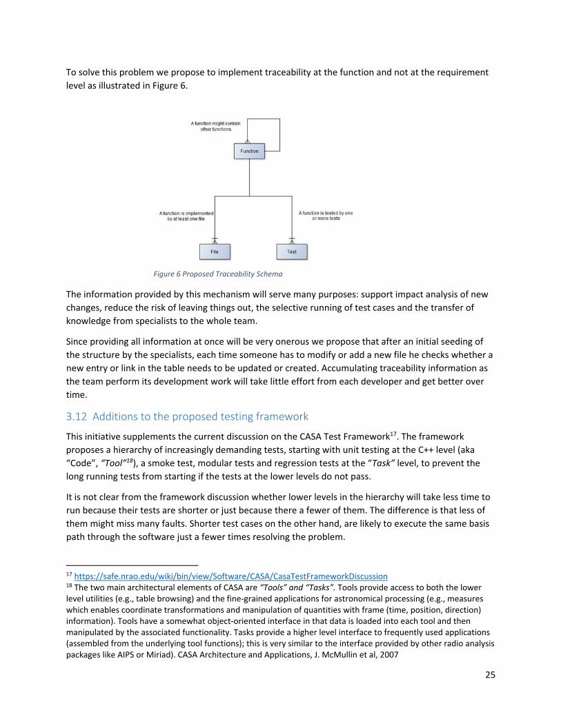
To solve this problem we propose to implement traceability at the function and not at the requirement
level as illustrated in Figure 6.
The information provided by this mechanism will serve many purposes: support impact analysis of new
changes, reduce the risk of leaving things out, the selective running of test cases and the transfer of
knowledge from specialists to the whole team.
Since providing all information at once will be very onerous we propose that after an initial seeding of
the structure by the specialists, each time someone has to modify or add a new file he checks whether a
new entry or link in the table needs to be updated or created. Accumulating traceability information as
the team perform its development work will take little effort from each developer and get better over
time.
3.12 Additions to the proposed testing framework
This initiative supplements the current discussion on the CASA Test Framework17. The framework
proposes a hierarchy of increasingly demanding tests, starting with unit testing at the C++ level (aka
“Code”, “Tool”18), a smoke test, modular tests and regression tests at the “Task” level, to prevent the
long running tests from starting if the tests at the lower levels do not pass.
It is not clear from the framework discussion whether lower levels in the hierarchy will take less time to
run because their tests are shorter or just because there a fewer of them. The difference is that less of
them might miss many faults. Shorter test cases on the other hand, are likely to execute the same basis
path through the software just a fewer times resolving the problem.
17 https://safe.nrao.edu/wiki/bin/view/Software/CASA/CasaTestFrameworkDiscussion 18 The two main architectural elements of CASA are “Tools” and “Tasks”. Tools provide access to both the lower level utilities (e.g., table browsing) and the fine‐grained applications for astronomical processing (e.g., measures which enables coordinate transformations and manipulation of quantities with frame (time, position, direction) information). Tools have a somewhat object‐oriented interface in that data is loaded into each tool and then manipulated by the associated functionality. Tasks provide a higher level interface to frequently used applications (assembled from the underlying tool functions); this is very similar to the interface provided by other radio analysis packages like AIPS or Miriad). CASA Architecture and Applications, J. McMullin et al, 2007
Figure 6 Proposed Traceability Schema

26
To address this problem we propose to use for types of test cases: “Canonical”, “Reference”,
“Application” and “Performance” which we distinguish from the purpose of the test, e.g. “unit”,
“smoke”, “regression”, etc. We also propose to use branch coverage to improve the thoroughness of
test suites.
3.12.1 Test types
3.12.1.1 Canonical test cases
Canonical tests are based on synthetic data whose purpose is to detect whether after a change, given
the same input the software produces the same output. Canonical test cases are not new. Figure 7
illustrates an old TV adjustment signal used to calibrate and repair analog TV equipment. In the CASA
case, a team from ESO lead by Dr. L. Cortese proposed to use synthetic data to test the performance of
imaging algorithms19.
The expected result for these test cases will be set when the tests are created under the assumption the
software is correct. Once defined, the test cases will be used as invariants with respect to themselves. If
subsequent to a software modification, the test detects an unexpected change in the output value the
code should be investigated. A large number of short canonical tests can be used to achieve a high
coverage of the software under test and provide an easy identification of the offending code.
3.12.1.2 Reference tests
Reference tests are standardized tests used to check the quality of the processing. Reference tests could
be based on synthetic or real data, what distinguishes them is that they are under configuration control
and exhibit characteristics peculiar to what needs to be tested. Besides testing, reference test cases can
be used to specify requirements by stating how a particular feature should appear after the change.
19 Formal Tests of CASA Imaging; L. Cortese, R. Galvan‐Madrid, P. Klaassen, S. Longmore, D. Petry; ESO; January 2011 ‐ May 2012
Figure 7 Old "canonical" TV signal

27
3.12.1.3 Application tests
Application test are based on real data and used to validate the code developed.
3.12.1.4 Performance tests
Performance tests could be based on synthetic or real data and their results are baselined. They must
run in a designated environment in order for the results to be comparable from run to run. These tests
respond to different scenarios and their purpose is to collect system performance metrics and verify
that the changes introduced do not negatively affect the system performance.
Test purpose
Table 2 identifies the different purpose of the test and the type of test case that could be used.
3.12.1.5 Unit testing
Currently testing of the CASA tools (aka: “Code” or C++ level) is ad‐hoc. What is called unit testing by the
CDG is testing at the task level. We fully agree with the need to implement automated and systemic
testing at the unit level using a testing framework like googletest (open source) or Parasoft
(commercial).
Besides the obvious benefits of catching faults earlier, having automated unit tests at the tool level will
allow developers to consistently run a test suite before committing the modified code to the software
repository minimizing the risk of breaking the build. This type of capability is mandatory if NRAO is to
implement an automated deployment pipeline and to perform refactoring of the code.
It is recommended that the developers familiarize with xUnit testing patterns20 to produce resilient test
code before they start this work.
Table 2 Relation of test types and test purpose
Purpose of the test
Unit Task Regression Validation Acceptance Type of test
Canonical +++ ++ +++
Reference +++ +++ ++ +++ +++
Application + ++ ++
Performance For profiling +++ +++ +++
The number of “+” indicates the level of preference
20 G. Meszaros, xUnit Test Patterns: Refactoring Test Code, Addison‐Wesley, 2007
28
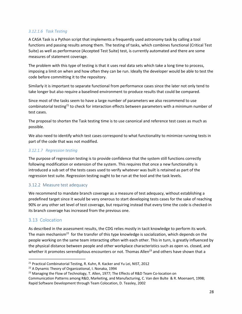
3.12.1.6 Task Testing
A CASA Task is a Python script that implements a frequently used astronomy task by calling a tool
functions and passing results among them. The testing of tasks, which combines functional (Critical Test
Suite) as well as performance (Accepted Test Suite) test, is currently automated and there are some
measures of statement coverage.
The problem with this type of testing is that it uses real data sets which take a long time to process,
imposing a limit on when and how often they can be run. Ideally the developer would be able to test the
code before committing it to the repository.
Similarly it is important to separate functional from performance cases since the later not only tend to
take longer but also require a baselined environment to produce results that could be compared.
Since most of the tasks seem to have a large number of parameters we also recommend to use
combinatorial testing21 to check for interaction effects between parameters with a minimum number of
test cases.
The proposal to shorten the Task testing time is to use canonical and reference test cases as much as
possible.
We also need to identify which test cases correspond to what functionality to minimize running tests in
part of the code that was not modified.
3.12.1.7 Regression testing
The purpose of regression testing is to provide confidence that the system still functions correctly
following modification or extension of the system. This requires that once a new functionality is
introduced a sub set of the tests cases used to verify whatever was built is retained as part of the
regression test suite. Regression testing ought to be run at the tool and the task levels.
3.12.2 Measure test adequacy
We recommend to mandate branch coverage as a measure of test adequacy, without establishing a
predefined target since it would be very onerous to start developing tests cases for the sake of reaching
90% or any other set level of test coverage, but requiring instead that every time the code is checked‐in
its branch coverage has increased from the previous one.
3.13 Colocation
As described in the assessment results, the CDG relies mostly in tacit knowledge to perform its work.
The main mechanism22 for the transfer of this type knowledge is socialization, which depends on the
people working on the same team interacting often with each other. This in turn, is greatly influenced by
the physical distance between people and other workplace characteristics such as open vs. closed, and
whether it promotes serendipitous encounters or not. Thomas Allen23 and others have shown that a
21 Practical Combinatorial Testing, R. Kuhn, R. Kacker and Yu Lei, NIST, 2012 22 A Dynamic Theory of Organizational, I. Nonaka, 1994 23 Managing the Flow of Technology, T. Allen, 1977; The Effects of R&D Team Co‐location on Communication Patterns among R&D, Marketing, and Manufacturing, C. Van den Bulte & R. Moenaert, 1998; Rapid Software Development through Team Colocation, D. Teasley, 2002

29
separation of around 60 feet cuts by half the probability of weekly technical communications between
two persons working in the same team. This gets worse if people work in different floors or different
locations.
So this recommendation is about colocating the CDG within their two locations: Charlottesville and
Socorro and providing common spaces to promote spontaneous exchanges among team members. See
Figure 8.
At each location, the CDG team members should be seated together in one floor, along the same
corridor while providing unreserved meeting places – perhaps one or two offices without doors and
white walls for the quick sketching of ideas –, information radiators24. This combination of closed offices
and common areas will promote collaboration while preserving privacy and concentration.
Colocation will go a long way towards breaking down the functional silos within the development group,
it will provide opportunities for cross‐training and contribute towards the feeling of purpose 9 of the
CDG members.
3.14 Repaying CASA’s technical debt
The term “technical debt” refers to the increasing cost of maintaining a system resulting from practices
that are expedient on the short term but tend to cause difficulties in the long term. It is an analogy with
somebody living on credit and eventually being unable to repay and be forced into bankruptcy or in the
case of a software system having major problems every time a change is made.
In the case of the CDG, technical debt manifest as a lack of system level documentation, design rules,
insufficient test cases, uncontrolled interfaces, a variety of programming styles, lack of automation and
supporting tooling.
As part of the technical debt repayment we suggest:
1. Use a tool like Coverity Architecture Analysis, Lattix or Structure101 to: 1) reconstruct the design
of the CASA code, 2) guide the refactoring effort and 3) enforce design rules and follow the
evolution of the code base.
24 An information radiator, is a publicly posted display that shows people walking by what is going on. Information radiators convey for example information about the status of development to the team and management. Alastair Cockburn says an information radiator “displays information in a place where passersby can see it. With information radiators, the passersby don’t need to ask questions, the information simply hits them as they pass.”, A. Cockburn, Agile Software Development: The Cooperative Game, 2001
Shared space
Shared space
Figure 8 Colocated space design. The shared unreserved space will promote serendipitous encounters

30
2. Conduct an analysis of the code base and the change history to identify the highest volatility
components and those most fault prone to prioritize any refactoring effort.
3. Refactor the code.
4. Develop additional test cases
5. Set up a common development environment, including the use of static analysis tool
6. Include automatic quality gates in the check‐in procedure
3.15 Coding guidelines
A software program is written once but read many times. Naming and coding conventions are very
important if any programmer must be able to look at another's code and quickly understand it.
Currently the CDG has some coding conventions, but as mentioned during the interviews these are not
consistently applied nor enforced.
It is recommended that the group choose appropriate guidelines for each of its code bases, for example
Google Style Guide for C++ and PEP‐8 for Python, and enforce its application either by automatic means,
e.g. style checker or through code reviews.
As with other initiatives this also must be applied in an incremental fashion since refactoring the code to
comply with the chosen guidelines, all at once, would be prohibitively costly.
3.16 CASA roadmap
The CASA roadmap would describe the planned evolution of the CASA software to internal and external
audiences over the next four to six quarters, so they could plan their own work accordingly. The
roadmap ought to be a living document regularly updated and approved by the senior management.
The roadmap will show what things the CDG plans to work on. Typically this will be a combination of
user and CDG proposed features or enhancements to the software.
The roadmap will link the work of the CDG to preconditions, e.g. the availability of a new compiler, and
external events, e.g. an approved research project that needs a new functionality. See Figure 9.
Q1 Q2 Q3 Q4 Q1 Q2
User community/ Theme
Features and enhancements
Technology
External events
Figure 9 CASA Roadmap

31
The User community/Theme in Figure 9 refers to any particular subset of users25, e.g.: “Early Career”,
“University/College”, and “Optical/IR Experience” or theme, e.g. “single dish support” targeted on a
particular quarter. This will be used internally to schedule work requests of a particular type and
externally to manage expectations.
Features and enhancements: Are a concise description of what is planned for delivery on in a given
quarter. Typically this will be a combination of user and CDG proposed features or enhancements to the
software.
Technology. Any technology that needs to be available by the time the features and enhancements are
to be delivered. If the technology in question is not available it is unlikely the features planned for that
quarter could go into production.
External events. This refers to science or construction events that require a new functionality. For
example the beginning of an observation period following the approval of science proposals could be an
external event.
3.17 Training
Institutionalize a training program to familiarize software developers with the radio astronomy domain
and radio astronomer with basic software engineering principles. This initiative is key to bridging the “us
vs. them” divide. Ask developers to explain their own subsystems to the group.
This initiative could be implemented by means of brown bag seminaries or similar mechanism. It could
also be used as a recognition mechanism to knowledge mastery9 by inviting experts to talk about their
areas of expertise, vision for the future and discipline.
4 Implementation strategy
As reflected by our first recommendation “Implement alternate periods of development and
housekeeping”, we favor an incremental approach to process improvement.
Since NRAO has not yet decided which recommendations will implement or how many people will
allocate to work on then and when it is impossible to provide the agency with a specific plan of action.
As an alternative this section focus on identifying dependencies between activities, see Figure 10, that
will help NRAO define the order in which to tackle them once the above decisions are made.
NRAO should start the process by creating an end‐to‐end blueprint to guide the implementation and
communicate the vision to external and internal stakeholders.
Second it should allocate the work to each housekeeping increment. If NRAO decides to adopt the
“CASA Roadmap” recommendation, it should document the work to be done there.
Each recommendation should be implemented within a single period to be sure it can be validated in
the subsequent development period and must an owner that is accountable for everything necessary to
achieve the goal sought, e.g. tools, procedures, migration strategy, training and measurements. A
reasonable first approximation to ownership will be to assign all work in a given area to the person
25 2015 CASA User Survey

32
responsible for that area of work, e.g. project management work to the Project Manager and build work
to the B&T Lead. The CGL should be responsible for those recommendations directly targeting the
welfare and culture of the group and those requiring interactions or budgetary approval from NRAO,
e.g. “Colocation” and “Implementing Alternate Development and Housekeeping Periods”. The CGL
should be also the speaker for the improvement initiative at all levels of the organization and externally.
All improvement work should comply and, whenever possible, use the documentation templates
developed by PMD and when not, leverage their expertise in system engineering processes and
techniques to assist with the development and deployment of tailored ones.
Figure 10 End‐to‐end dependency relations between recommendations. Work on a recommendation can start at any time, but cannot be completed until all predecessors have been completed

33
Appendix A. Improvement Areas
Introduction
As part of their mandate to provide program and project management support and systems engineering
services to NRAO and to develop all user facing software, e.g.: CASA, AIPS++ and PST, the Assistant
Director for Program Management – Lory Wingate and the Assistant Director for Data Management &
Software – Brian Glendenning jointly launched the EVALUATION OF CASA PMD REQUIREMENTS project
which consists of the:
a. Assessment of current software development and software project management processes
against best practices frameworks such as those published by the Project Management Institute
(PMI), the International Council on Systems Engineering (INCOSE) or the Software Engineering
Institute’s Capability Maturity Model (CMMI)
b. Recommendation of improvements
c. Provision of a basic implementation plan, including recommended qualifications for personnel
to implement the recommendations
This report covers the results of the process assessments, deliverable “a” above, conducted between
July 15th and July 24th, 2015 at the Charlottesville and Socorro offices of NRAO. In total 21 persons were
interviewed. The assessment was carried out in a constructive atmosphere. The recommendation for
improvements and the implementation plan, deliverables “b” and “c” above will be provided at a later
time, after consultation with NRAO’s leadership.
The CMMI26 is a collection of good software and system development practices organized in five levels
of increased maturity developed by the Software Engineering Institute under the auspices of the
Department of Defense that has been widely adopted27 throughout the world by governments and
commercial organizations as well. It is important to remark at this point, that the maturity level of an
organization does not reflect whether it can produce or not some very exciting and successful software,
but in the organization’s ability to efficient and consistently deliver on the commitments it makes.
Projects executing at Level 2 of the CMMI maturity scale are characterized as projects following basic
accepted practices such as planning, tracking and configuration management; executed by people
trained in tasks they are going to perform; with adequate resources to deliver the expected results;
involving relevant stakeholders and audited to verify compliance with the processes they had set for
themselves.
The assessment of current practices was originally planned to cover all Level 2 process areas and the
technical implementation and risk management process areas of Level 3. Of the thirteen originally
planned process areas, the assessment only covered ten of them as responses to previous questions
rendered further inquiry inconsequential.
26 This document assumes the reader has a basic knowledge of the CMMI model; if this not the case, please refer to Appendix A for a brief
description.
27 Over 10,000 organizations assessed worldwide as of 2014. Level 2, 21%; Level 3, 66%; Level 4, 2%; Level 5, 7%

34
In the last years, the CASA Development Group, from here on referred simply as the group, has
implemented, with varying degree of success, a number of initiatives like the use of the JIRA28 tool to
track the assignment and progress of work, a new build and test environment, the migration to a
distributed version control system, regular project status (Monday’s) meetings and the introduction of
the software architect and project management roles. While not diminishing the importance and
positive impact of some of these initiatives, the assessment identified a number of weaknesses such as
the lack of defined procedures for most of the processes assessed, unclear roles and responsibilities,
minimal or no existing system level documentation, the nonexistence of quality assurance mechanisms
capable of enforcing any design rule or mandated convention and the lack of a strategic vision and a
feature roadmap for the CASA software all of which prevent the organization from performing at a
higher maturity level. Although not part of the original mandate, the assessment also revealed a
mounting “technical debt”29 which keeps increasing the effort required to fix the software and develop
new features, a tension between the CASA software as a product or as a research platform, insufficient
or uneven involvement of the science user community and some people issues. These last concerns are
not within the purview of the group to resolve and will require senior management involvement to be
overcome.
The group copes with the process issues through various mechanisms: centralized decision making, the
leadership of knowledgeable individuals with a long tenure in the organization, a long period of
assimilation through which new employees must pass and the extreme specialization of the personnel.
These mechanisms are enabled by a low turnover rate resulting from the love of the members of the
group for the work they do, the location of NRAO offices in areas with low demand for software
engineers and family relations. These mechanisms however, are not without drawbacks: bottlenecks,
feelings of disempowerment, the risk posed by the departure of any individual and long ramp‐up
periods which not only makes almost impossible for one developer to help another when the situation
demands it, but has also resulted in the breakdown of the identity of the group as such and the
pigeonholing of its members. These consequences are in no way attributable to a single individual or
period of time, but the result of a cumulative process that keeps reinforcing itself.
As people’s motivation and having the necessary time to change are the ultimate determinants of the
success or failure of any improvement initiative, the need to refactor the CASA software to diminish its
technical debt, the time allocation of science users to the CASA group and the people issues will need to
be addressed together with the more specific recommendations concerning the software development
process, documentation and quality assurance for this initiative to succeed.
The rest of the document is organized as follows: The process followed for evaluating current practices,
the result of the assessment and its interpretation, next steps and appendixes.
Assessment results and interpretation
The assessment results confirmed the initial perceptions held by senior management that the group was
most likely working at Level 1 of the SEI maturity scale, but that the knowledge, tenure and work ethic
28 JIRA is an issue tracking system developed by Atlassian, https://www.atlassian.com/
29 The term “technical debt” refers to the increasing cost of maintaining a system resulting from practices that are expedient on the short term
but tend to cause difficulties in its long term. It is an analogy with somebody living on credit and eventually being unable to repay and be forced
into bankruptcy or in the case of a software system having major problems every time a change is made.

35
of the employees compensated for the lack of maturity in its processes. The same perception was
shared by the employees, who although aware about the changes required to improve their
development process felt demotivated to carry them out.
It is important to note here that when we refer to the lack of guidelines or claim that a given process is
not performed or something is unclear, we are doing this from an organizational and not an individual
perspective. Sometimes a document or proposed procedure does exist, as a matter of fact some of them
have been provided to assessor by different interviewees, but if they remain unknown to other
practitioners or if a given process is not performed by all, for the purpose of this assessment they were
considered lacking or not satisfied. Similarly when referring to other problems such as insufficient time
to perform a task or people issues, they were included in the report only if mentioned directly or
inferred through remarks made during the interviews by more than one individual.
Table 3 summarizes the result of the assessment for the process areas evaluated.
Process maturity
The group lacks documented or otherwise agreed organizational guidelines for most of the process
areas assessed. Specifically there is very little in the form of common processes other than development
starts with a JIRA ticket that is assigned to one developer and that after the coding is done it should be
tested, first internally and second by a science user. There is no planning other than the ordering of
tickets according to priority and code freeze dates. There is no capacity planning at the developer level
to determine tentative dates for delivery. Progress reporting is ad‐hoc and there is no comparison of
planned versus actual values that would allow the improvement of the estimation process. There are no
quality assurance30 mechanisms capable of enforcing any decisions concerning coding conventions,
design rules or any other process for the matter. There is no root cause analysis following a problem nor
a defect prevention process in place. In terms of configuration management, there is a version control
system in place but there are no explicit activities designed to keep, for example code and tests in
synchrony, no traceability from tickets to work product and vice versa nor configurations audits. This
lack of processes result in long ramp‐up times for new employees and imposes a centralized decision
making and coordination style that not only lengthens the processes’ lead times but also results on a
feeling of disempowerment among the employees.
Process Efficiency
Only three out of six developers in Socorro reported lead times and process times during the interview.
The three indicated long lead times, in the order of months, for tasks that would only take weeks to
complete (process time). The three main culprits identified for this were: the time it takes to clarify
requirements and bugs reports, the time it takes to get user testing done and get feedback on the code
developed. Of the three developers that responded, only one reported completion and accuracy
indicating that around 50% of the tasks performed required rework after being declared completed.
The assessment did not find evidence of automated unit testing at the C++ level, although there seems
to be an initiative in this regard31. The so called “automated unit testing” is performed at the Python
30 Quality assurance should not be confused with testing. QA is designed to make sure organizations do as they say they will. 31 https://safe.nrao.edu/wiki/bin/view/Software/TestCppEvalDocumentation, accessed Aug. 3, 2015.

36
level invoking the C++ code, so it is more what would be called integration or function test in other
organizations. This process produces a coverage32 report that is accessible through the Casa Wiki33 but
there was no indication of how or by whom the reported information is used. The coverage number
reported, 30%, points towards insufficient testing. There are no canonical test cases that could be used
as test oracles or to specify new features.
Use of tools to automate routine tasks such as verifying coding conventions or generate test cases are
not used. See the section on tools for more details.
32 Coverage refers to number of elements, lines of code, methods, branches, paths that are exercised by a test suite. It is usually expressed as a
percentage. A 30% statement coverage means that only 30% of the total number of lines of code in a program was executed by a test suite
33 https://safe.nrao.edu/wiki/bin/view/Software/TestCoverageAnalysisDocumentation, accessed Aug. 5, 2015

37
Table 3 Summarized assessment result
Process Area Description Assessment
Requirements Management
The purpose of Requirements Management is to manage the requirements of the project’s products and product components and to identify inconsistencies between those requirements and the project’s plans and work products.
Not satisfied. Process is not documented nor efficient
Project Planning
The purpose of Project Planning is to establish and maintain plans that define project activities.
Not satisfied. Process is not documented nor efficient
Project Monitoring and Control
The purpose of Project Monitoring and Control is to provide an understanding of the project’s progress so that appropriate corrective actions can be taken when the project’s performance deviates significantly from the plan.
Not satisfied. Process is not documented nor efficient
Measurement and Analysis
The purpose of Measurement and Analysis is to develop and sustain a measurement capability that is used to support management information needs.
Not assessed
Process and Product Quality Assurance
The purpose of Process and Product Quality Assurance is to provide staff and management with objective insight into processes and associated work products.
Non‐existent
Configuration Management
The purpose of Configuration Management is to establish and maintain the integrity of work products using configuration identification, configuration control, configuration status accounting, and configuration audits.
Not satisfied. Mostly code version control. No traceability
Requirements Development
The purpose of Requirements Development is to produce and analyze customer, product, and product component requirements.
Not satisfied. Ad‐hoc
Technical Solution
The purpose of Technical Solution is to design, develop, and implement solutions to requirements. Solutions, designs, and implementations encompass products, product components, and product‐related life‐cycle processes either singly or in combinations as appropriate.
Not satisfied. Process are not documented nor efficient
Product Integration
The purpose of Product Integration is to assemble the product from the product components, ensure that the product, as integrated, functions properly, and deliver the product.
Not assessed
Verification The purpose of Verification is to ensure that selected work products meet their specified requirements.
Not satisfied. Process is not documented nor efficient
Validation The purpose of Validation is to demonstrate that a product or product component fulfills its intended use when placed in its intended environment.
Not satisfied. Process is not documented nor efficient

38
Risk Management
The purpose of Risk Management is to identify potential problems before they occur so that risk‐handling activities may be planned and invoked as needed across the life of the product or project to mitigate adverse impacts on achieving objectives.
Not satisfied. Ad‐hoc
Decision Analysis and Resolution
The purpose of Decision Analysis and Resolution is to analyze possible decisions using a formal evaluation process that evaluates identified alternatives against established criteria.
Not assessed
Supplier Agreement Management
The purpose of Supplier Agreement Management is to manage the acquisition of products and services from suppliers.
Used to evaluate relationship with ESO and NAOJ. Not satisfied. Process is not documented
People issues
On the people side, the assessor found people reluctant to take initiatives outside their area of
immediate concern or to assume leadership roles for fear to be “burned”, not by their own doing but by
a lack, real or perceived, of empowerment to fulfill the role. This coupled with the extreme
specialization has resulted in a silo culture in which success is achieved by doing well on your own little
niche rather than looking at the whole CASA system. In turn, this reluctance has forced management to
do all coordination work and to make decisions that could be done at a lower levels which ends up
reinforcing the original perception of the employees which in turn confirms the view of the managers.
In addition to this, the complexity of the domain also contributes to feelings of subordinateness as most
astronomers can program, which is not the same as saying they are capable software engineers34, but
not all programmers can do or understand radio astronomy in the same proportion.
History and personalities were frequently mentioned as the main hurdles to improve the development
process.
Project scientists
Project scientists play key roles in the development of the CASA software. They are the responsible for
clarifying requirements and validating results.
In the current process, these two activities are in the critical path of most bug fixes and new feature
development and in consequence every delay in responding to a question or in testing a part of the
software adds to the development lead time so work is frequently started without having clear
requirements. This is clearly a problem since late clarifications usually result in rework. Similarly, user
validation might take place weeks after the developer has moved to work on new task and closer to the
release deadline, imposing a disruption that affects the developer’s productivity as well as that of those
who it might be collaborating with.
34 The systematic application of scientific and technological knowledge, methods, and experience to the design, implementation, testing, and documentation of software. Systems and software engineering ‐ Vocabulary, ISO/IEC/IEEE Std 24765:2010(E)

39
The root of the problem seems to be the insufficient time allocation of science users, a management
decision, to these two critical functions and the unpredictability of the requests generated by the group,
a consequence of the lack of planning.
Technical debt
Over the years the CASA software has accumulated a large technical debt. Development of new features
is prioritized over architecting and documentation until the cost of changing and keeping the software
running makes patently obvious the need to refactor it. There is no up to date comprehensive software
documentation, the few conventions that exist are used sparingly, there is not automated unit testing at
the C++ level and the thoroughness of whatever testing is being performed is unknown. There is no
formal analysis of the impact of a change in existing or future functionality and no control of the
interfaces among subsystems. There is no defined criteria to be met before code can be committed.
The ever increasing difficulty of making changes diminish the productivity of team forcing them to take
new shortcuts, compounding this way the situation and making them less responsive to user requests.
CASA strategic vision
There is no public strategic vision and feature roadmap available to developers and users alike. In this
context, feature requests, prioritization and design are made almost in the dark. If developers knew
where the software is going and what is coming down the road they could design features today in such
a way to facilitate and not hinder future development. Stakeholders, whether internal or external, need
information about future development in order to plan their activities. Hence, the demand for an overall
view of the product and offerings is really important.
Product vs. research platform
CASA is seen by many, inside and as well as outside the CDG, as a product to do their astronomical
research or as a platform for developing new radio astronomy imaging and analysis techniques. Both
views are valid but they conflict at times. Depending on whether the software is seen as a product or as
a research platform, users and developers have different expectations and goals. As a product, users
expect35 CASA to be reliable, performant, user friendly, supported and timely delivered. As a research
platform, users are willing to live with a few bugs and harsh corners as the price to pay for having an
exciting new feature now rather than in a few months. They also understand that research is an
exploration process and so getting it right might take longer than initially foresaw.
From a development perspective, the current process does not acknowledge these differences and
mundane development is intermingled with research affecting predictability in one case and velocity in
other whit the end result of unfulfilling the expectations of both.
Competence development
Although some developers have taken the Synthesis Imaging Workshop or part of it, the assessment did
not identify any required training, either for developers to learn about the application domain or for
astronomers and scientists to learn software engineering.
35 NRAO Users Committee Report 2014, Section 3.2, September 22, 2014

40
Tools
Beside the traditional development tools such as editors, compilers, make files, and version control
system the group does not make use much of modern software engineering tools that could increase
productivity and robustness.
The common tool inventory includes SVN and Git for version control. Jenkins to lunch the build process
and two series36 of automated test cases using the Robot Framework and NOSE. Both series of tests run
at the Python level. Statement and branch coverage are reported by a NOSE Plugin but during the
assessment nobody mentioned using this information to improve their test suite.
JIRA, an issue tracking system, is at the center of the development process. It is used to assign and track
work, as a requirements management tool, as a communication tool and as a trouble report system.
The following are deficiencies worth noting:
No automated testing of C++ code
No automated testing of the user interface, although an initiative to use Selenium for this is
being considered
No use of static analysis tools such as pylint and prospector for python, nor for C++ such as
CppLint, CppDepend, Klockwork, etc. to enforce design rules and good coding standards before
committing code
No use of combinatorial testing tools to maximize interaction testing while minimizing the
number of test cases
No language aware Integrated Development Environment (IDE)
No tool for design recovery
36 “Critical” tests run nightly and “Acceptance” tests that takes longer to run

41
Appendix B. RACI Analysis Method
This appendix provides an introduction to the RACI method.
Role & ResponsibilityCharting (RACI)
By Michael L Smith and James Erwin
See RACI Template too.By Sandra Diaferio

Role & Responsibility Charting
Page 2 of 14
OVERVIEW
Definition
Responsibility Charting is a technique for identifying functional areas where thereare process ambiguities, bringing the differences out in the open and resolvingthem through a cross-functional collaborative effort.
Responsibility Charting enables managers from the same or differentorganizational levels or programs to actively participate in a focused andsystematic discussion about process related descriptions of the actions that mustbe accomplished in order to deliver a successful end product or service.
Approach Definitions
Responsibility Charting is a way of systematically clarifying relationshipspertaining to:
1. Communication or actions required to deliver an acceptable product ror service
2. Functional roles or departmental positions (no personal names).3. Participation expectations assigned to roles by decisions or actions.
ProcessModel
FunctionalRole
FunctionalRole
FunctionalRole
FunctionalRole
FunctionalRole
Decisionsor Actions

Role & Responsibility Charting
Page 3 of 14
THE RESPONSIBILITY CHARTING THEORY
Managers and supervisors are not accountable for everything in theirorganization. Responsibility charting ensures accountability is placed with theperson who really can be accountable for specific work. Often this results inaccountabilities for actions being moved down to the most appropriate level.
Everyone has some process role in their job. Because of differing perceptions,one person’s view of their role may be quite different than another’s. Roleperceptions held today will change tomorrow even though the job activitiesremain the same. There are three (3) basic assumptions in any role. They are:
1. ROLE CONCEPTION: What a person thinks his/her job is andhow the person has been taught to doit. His/her thinking may well beinfluenced by many false assumptions(e.g., misleading titles, training receivedfrom a predecessor during his or herlast week on the job, etc.)
2. ROLE EXPECTATION: What others in the organization thinkthe person is responsible for, and howhe/she should carry out thoseresponsibilities. Others’ ideas may alsobe influenced by incorrect information(e.g., the way it was at a former job,priority changes, assumptions,inconsistent messages from leadership,etc.). The role expectation is usuallybased on the output of results expectedfrom the role.
3. ROLE BEHAVIOR: What a person actually does in carryingout the job.

Role & Responsibility Charting
Page 4 of 14
Responsibility charting reconciles ROLE CONCEPTION with the ROLEEXPECTATION and thus, ROLE BEHAVIOR becomes more predictable andproductive!. Ideally, what a person thinks his or her hob is, what others expect ofthat job, and how the job is actually performed are all the same. The “RACI”process is a tool to lock all elements in place. Working with other “processproviders” provides a real time consensus that clarifies “who is to do what, withwhom and when. This is of great benefit for overall process performance.
A substandard product or process can often be tracked back to a fault in thechart. Common faults in the chart include: an action not included on the chart(that should be), a position failing to perform as assigned or a missing ormisapplied responsibility code. The highly visible and collaborative nature of thecharting process promotes rapid and effective updates/corrections as well asbetter understanding by those involved in the work.
DIAGNOSING THE NEED
The need for managers and supervisors to clarify roles and responsibilities doesnot end after the Responsibility Charting process is complete; it must be anongoing activity. Managers need to acquire a “sixth sense” so they can recognizethe symptoms of role confusion and determine when the process needs to berepeated. Perception “drift” is natural. The identification and elimination of “drift”is important to the company’s overall well being as it relates to cost, service andquality.
The symptoms of role confusion are:
• Concern over who makes decisions• Blaming of others for not getting the job done• Out of balance workloads• Lack of action because of ineffective communications• Questions over who does what• A “we-they” attitude• A “not sure, so take no action” attitude• Idle time• Creation of and attention to non-essential work to fill time• A reactive work environment• Poor morale• Multiple “stops” needed to find an answer to a question

Role & Responsibility Charting
Page 5 of 14
ROLES AND RESPONSIBILITIESCHARTING DEFINITIONS
RESPONSIBLE…..”R”“The Doer”
The “doer” is the individual(s) who actually complete the task. The “doer” Isresponsible for action/implementation. Responsibility can be shared. Thedegree of responsibility is determined by the individual with the “A”.
ACCOUNTABLE…..”A”“The Buck Stops Here”
The accountable person is the individual who is ultimately answerable forthe activity or decision. This includes “yes” or “no” authority and vetopower. Only one “A” can be assigned to an action.
CONSULT……”C”“In the Loop”
The consult role is individual(s) (typically subject matter experts) to beconsulted prior to a final decision or action. This is a predetermined needfor two-way communication. Input from the designated position is required.
INFORM…..”I”“Keep in the Picture”
This is individual (s) who needs to be informed after a decision or action istaken. They may be required to take action as a result of the outcome. It isa one-way communication.

Role & Responsibility Charting
Page 6 of 14
Responsibility Chart The 5-Step Process
1. Identify work process Start with high impact areas first
• Don’t chart process that will soon change• Work process must be well defined
- Fewer than ten activities implies the definition is toonarrow
- Greater then 25 activities implies definition is toobroad
2. Determine the decisions and activities to chart
• Avoid obvious, generic or ambiguous activities, suchas:- “Attend meetings”- “Prepare reports”
• Each activity or decision should begin with a goodaction verb
Evaluate Schedule Write Record DetermineOperate Monitor Prepare Update CollectApprove Conduct Develop Inspect TrainPublish Report Review Authorize Decide
3. Prepare a list of roles or people involved in those tasks
Roles can be individuals, groups or entire departments
• Can include people outside your department our outside thecompany
- Customers, suppliers, etc.
• Roles are better than individual names

Role & Responsibility Charting
Page 7 of 14
- RACI chart should be independent of personalrelationships so the chart would still be valid if allnew people filled the roles tomorrow
4. Develop the RACI chart As a general rule, first assign R’s then determine who has the A, then complete C’s and I’s
• For larger groups or more complex issues, an independentfacilitator is required
• Meeting time can be significantly reduced if a “straw model”list of decisions and activities is completed prior to meeting
5. Get feedback and buy-in
• Distribute the RACI chart to everyone represented on thechart but not present in the development meeting
• Capture their changes and revise chart as appropriate• Reissue revised RACI chart• Update as necessary on a on-going basis
The ideal group size is four to ten people
A follow-up meeting may be necessary ifsignificant changes are made

Role & Responsibility Charting
Page 8 of 14
RACI CHARTINGAn Example
Mother Father John Sally Mark Kids*
Feed the dog A C RPlay with dog I I A RTake dog to vet R A/R CMorning walk C A/R REvening walk C A/R RWash dog C A/RClean up mess C A R
DEVELOPING THE ACTION LIST
An important element of Responsibility Charting is developing theactions to be charted and agreed upon. The lists can be developed inseveral ways. One effective way to gather information on functions,decisions, or activities is in a one-on-one interview. This interview is ananalytical questioning process and ranges from broad questions such as“what are the department’s objectives?” or, “what must the teamaccomplish?” to very specific questions involving inputs and outputs ofwork, to and from the participant.
An alternative to the interview is a group “brainstorm” or idea generationtechnique with representatives from the “process participant”departments. A facilitator would record the actions which then could befine-tuned in subsequent group meetings.

Role & Responsibility Charting
Page 9 of 14
R A C I Chart ReviewVertical Analysis
Finding Possible Interpretation
Lots of R’s Can this individual stay on top of so much?
No empty spaces Does the individual need to be involved in somany activities?
Too many A’s Can some of the accountability be “pusheddown” in the organization?
No R’s or A’s Is this a line position? Could it be expanded oreliminated?
Overall pattern Does the pattern fit the personality and style ofthe role occupant? Does it go against thepersonality type of the role occupant? (i.e.,either too much or too little involvement, etc.)
Roles / People
Decisions/Activities
C A C IA R C I C
C I R AR A
I A CA I R C
A C R I

Role & Responsibility Charting
Page 10 of 14
R A C I Chart ReviewHorizontal Analysis
Finding Possible Interpretation
Lots of R’s Will the task get done?Can activity or decision be broken into more specific tasks?
Lots of C’s Do all these individuals really need to be consulted? Do thebenefits of added input justify the time lost in consulting all theseindividuals?
Lots of I’s Do all these individuals really need to be routinely informed, orcould they be informed only in exceptional circumstances?
No R’s Job may not get done; everyone is waiting to approve, beconsulted, or informed; no one sees their role as taking theinitiative to get the job done.
No A’s No performance accountability; therefore, no personalconsequence when the job doesn’t get done. Rule #1 in RACIcharting: There must be one, but only one, “A” for eachaction or decision listed on the chart.
No C’s / I’s Is this because individuals/departments “don’t talk”?Does a lack of communication between individuals/departmentsresult in parallel or uninformed actions?
Roles / People
Decisions/Activities
C A C IA R C I C
C I R AR A
I A CA I R C
A C R I

Role & Responsibility Charting
Page 11 of 14
R A C I Closing Guidelines
1. Place Accountability (A) and Responsibility (R) at thelowest feasible level.
2. There can be only one accountable individual per activity
3. Authority must accompany accountability
4. Minimize the number of Consults (C) and Informs (I)
5. All roles and responsibilities must be documented andcommunicated
6. Discipline is needed to keep the roles and responsibilitiesclear. “Drift” happens. RACI has to be revisitedperiodically, especially when symptoms of role confusionreappear e.g.,
• Concern over who makes decisions• Blaming of others for not getting the job done• Out of balance workloads• Lack of action because of ineffective communications• Questions over who does what• A “we-they” attitude• A “not sure, so take no action” attitude• Idle time• Creation of and attention to non-essential work to fill time• A reactive work environment• Poor morale• Multiple “stops” needed to find an answer to a question
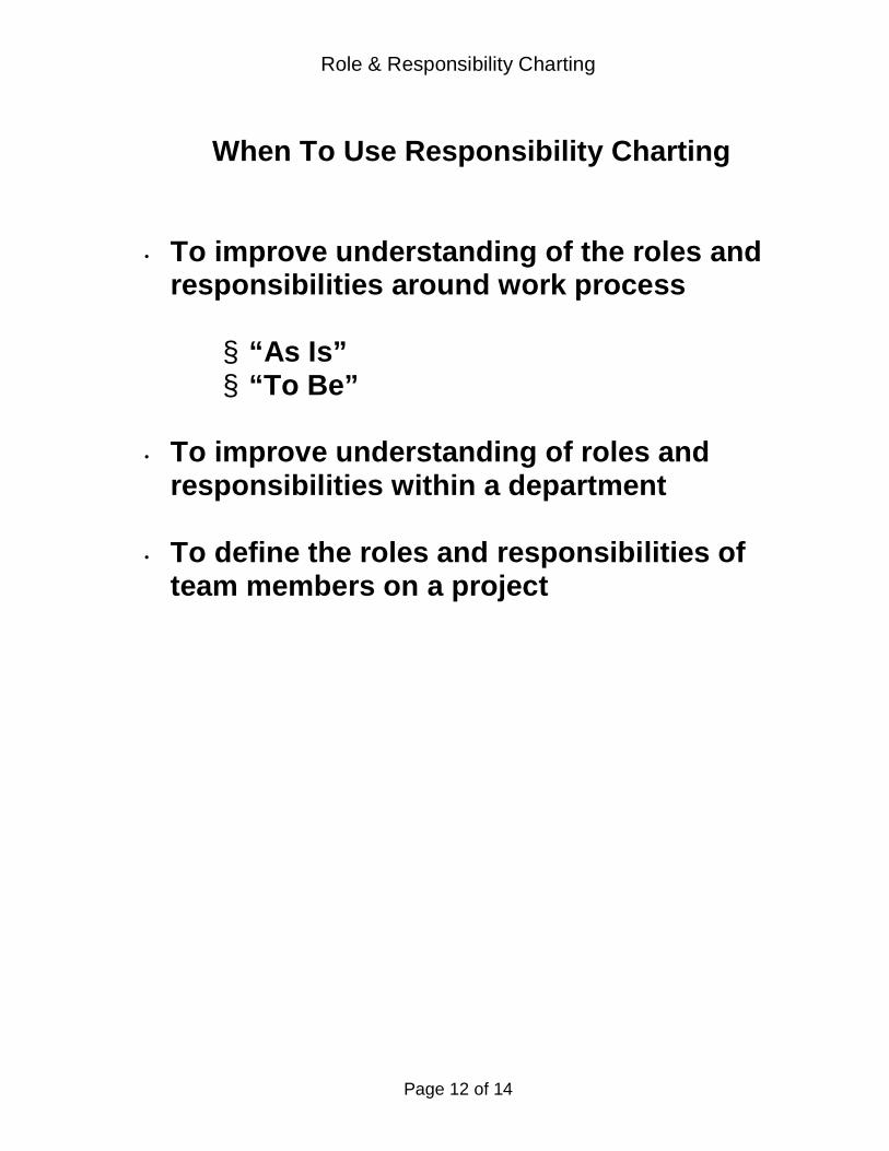
Role & Responsibility Charting
Page 12 of 14
When To Use Responsibility Charting
• To improve understanding of the roles andresponsibilities around work process
§ “As Is”§ “To Be”
• To improve understanding of roles andresponsibilities within a department
• To define the roles and responsibilities ofteam members on a project

Role & Responsibility Charting
Page 13 of 14
ROLES AND RESPONSIBILITIES CHARTING
Trying to get work done without clearly establishingroles and responsibilities, is like trying to parallel parkwith one eye closed.
What about role behavior? The RACI chart shows who doeswhat at a high level and their RACI role. If more specificity isneeded, and it often is, you can use process maps or list thesteps/decisions and document the specifics of what is done.
You can go from process maps to RACI or RACI to process maps
TS Reviews Ordersand assigns work byJob size/program and
staff skill
PlanningMeeting
Order Releaseput in Cage
PICK/PACK
Pick Mat'lfrom Batch
List/Pick Plan
Count Items
BrokenRange?
Write rangeand quantityon pick plan
Writeranges onpick plan
Scan Batch Listand Item ID
No
Yes

Role & Responsibility Charting
Page 14 of 14
Or, you can document your understanding of the role behavior bytaking the list from the RACI chart and listing the steps/decisionsand documenting the specifics of what is done. It’s as simple aswho, what, when, inputs and outputs. You can expect moreresistance clarifying the roles this way than just with RACI. Wenow know who is to do what with whom, and when in such a waythat each person is truly accountable for their part of the overallprocess.
Task /Decision
RACI Who What When Inputsfrom
Outputsto

56
Appendix C. CASA Notional Workflow
The notation used to describe the CASA Notional Workflow is called IDEF0. The basic element of an
IDEF0 model, as illustrated by Figure 11, is a box containing a verb phrase (e.g., “execute project”)
describing the activity or transformation that takes place within the box. In IDEF0 syntax, inputs are
shown as arrows entering from the left side of the box, while outputs are represented by arrows exiting
from the right side of the box. Controls are displayed as arrows entering the top of the box and
mechanisms are displayed as arrows entering from the bottom. Inputs, controls, outputs, and
mechanisms (ICOMs) are collectively referred to as “concepts.”
Figure 11 IDEF0 Diagram
IDEF0 models are organized hierarchically. The high‐level activity is represented by a shadow‐edged box.
The concepts entering or leaving the box at the higher level are “consumed” or “produced” by the
lower‐level activities. There is no need to match every lower‐level concept with another at a higher
level. This “tunneling” in IDEF0 terminology helps improve the readability of the diagrams by allowing
for details to be shown where appropriate. Complete information about the IDEF family of methods can
be found at http://www.idef.com.
Execute Project Inputs Things that are transformed into outputs. Scope of work, materials.
MechanismsTools and resources necessary to perform the task. Examples: project manager, qualified staff, Microsoft Project.
OutputsWork products, deliverables. Examples: A new product, a design
Controls Impose a constraint on how or when the activity is performed. Examples: A day of a week, a process or policy

Use
d A
t:A
utho
r:Eduardo M
iranda
Pro
ject
:CASA
Workflo
w
Not
es:
1 2
3 4
5 6
7 8
9 10
Dat
e:9/
29/2
015
Tim
e:03
:40:
23
Rev
:
Wor
king
Dra
ftR
ecom
men
ded
Pub
licat
ion
xR
EA
DE
RD
AT
E
Nod
e:C
2T
itle:
CASA
Development
Num
ber:
Pg
1
Con
text
Rep
ository: CASA
Workflo
w; Date: 9/29/2015
No
onal
A0
CASA
A0
clarifica
on
appeal
completed CUS
bug report (BR)
change req
uest (CR)
engineering change req
uest (ECR)
research req
uest (RR)
WR disposi
on
release no
ce
research rep
ort
CASA
user survey (CUS)
WR final disposi
on
reporng
correc
ve acon
escala
on
balanced scorecard
Jira+
Git
organiza
onal policies & tem
plates (...

Use
d A
t:A
utho
r:
Pro
ject
:CASA
Workflo
w
Not
es:
1 2
3 4
5 6
7 8
9 10
Dat
e:9/
26/2
015
Tim
e:14
:05:
06
Rev
:
Wor
king
Dra
ftR
ecom
men
ded
Pub
licat
ion
xR
EA
DE
RD
AT
E
Nod
e:C
3T
itle:
A0: C
ASA
Num
ber:
Pg
2
Con
text
Rep
ository: CASA
Workflo
w; Date: 9/29/2015
No
onal
A7
Quality
Assurance
A7
A6
CASA
Steering
A6
A5
Build
&Dep
loy
A5
A4
Technical
Debt
Rep
ayment A4
A3
CASA
&Pipeline
Development A3
A2
Workload
Managem
ent A2
A1
Process
Improvement A1
root causes
non‐compliance
opportunies
CASA
user survey (CUS)
escala
on
balanced scorecard
appeal
completed CUS
reconsidered
WR
CASA
Roadmap
WR final disposi
on
correc
ve acon
bug report (BR)
release no
ce
observa
ons, opinions and insights
design rules
design documenta
on
process traces
process traces
root causes
engineering change req
uest (ECR)
opportunies
bug report (BR)
research rep
ort
reporng
clarifica
on
process traces
crical BR
engineering change req
uest (ECR)
bug report (BR)
job
project
research project
change req
uest (CR)
research req
uest (RR)
WR disposi
on
process traces
processes
resource calendar
master sched
ule
daily
Git
master sched
ule
Jira+
master sched
ule
resource calendar
organiza
onal policies & tem
plates (...

Use
d A
t:A
utho
r:
Pro
ject
:CASA
Workflo
w
Not
es:
1 2
3 4
5 6
7 8
9 10
Dat
e:9/
26/2
015
Tim
e:13
:32:
34
Rev
:
Wor
king
Dra
ftR
ecom
men
ded
Pub
licat
ion
xR
EA
DE
RD
AT
E
Nod
e:C
12T
itle:
A1: Process Im
provement
Num
ber:
Pg
3
Con
text
Rep
ository: CASA
Workflo
w; Date: 9/29/2015
No
onal
Instu
onalize New
Process A14
Pilot Process
A13
Improve Process
A12
Develop Im
provemen
t Proposals
A11
processes
validated
process
feed
back
adjustmen
t
new
process
improvemen
t proposal
root causes
non‐compliance
design rules
opportunies
measuremen
ts
best pracces
organiza
onal policies & tem
plates (...
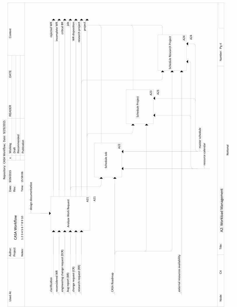
Use
d A
t:A
utho
r:
Pro
ject
:CASA
Workflo
w
Not
es:
1 2
3 4
5 6
7 8
9 10
Dat
e:9/
26/2
015
Tim
e:15
:58:
06
Rev
:
Wor
king
Dra
ftR
ecom
men
ded
Pub
licat
ion
xR
EA
DE
RD
AT
E
Nod
e:C
4T
itle:
A2: W
orkload
Managem
ent
Num
ber:
Pg
4
Con
text
Rep
ository: CASA
Workflo
w; Date: 9/29/2015
No
onal
A24
Sched
ule Research Project
A24
A23
Sched
ule Project
A23
Sched
ule Job
A22
A21
Analyze Work Req
uest
A21
external resources availability
CASA
Roadmap
clarifica
on
reconsidered
WR
engineering change req
uest (ECR)
bug report (BR)
change req
uest (CR)
research req
uest (RR)
WR disposi
on
incomplete W
R
rejected
WR
project
job
crical BR
research project
resource calendar
master sched
ule
design documen
taon

Use
d A
t:A
utho
r:
Pro
ject
:CASA
Workflo
w
Not
es:
1 2
3 4
5 6
7 8
9 10
Dat
e:9/
26/2
015
Tim
e:15
:58:
45
Rev
:
Wor
king
Dra
ftR
ecom
men
ded
Pub
licat
ion
xR
EA
DE
RD
AT
E
Nod
e:C
5T
itle:
A21: A
nalyze W
ork Req
uest
Num
ber:
Pg
5
Con
text
Rep
ository: CASA
Workflo
w; Date: 9/29/2015
No
onal
Classify Work
Req
uest
A215
(T‐Shirt) Esmate
Req
uest
A214
Elaborate Req
uest
A213
Assign Req
uest
A212
A211
Verify Req
uest
Quality
A211
project
job
research project
size
reconsidered
WR
clarifica
on
elaborated work req
uest
assigned
WR
crical BR
bug report (BR)
change req
uest (CR)
research req
uest (RR)
engineering change req
uest (ECR)
veed
WR
incomplete W
R
rejected
WR
WR disposi
on
Developer
Project Scien
st
design documenta
on
Project M
anager
master sched
ule
resource calendar
Jira+
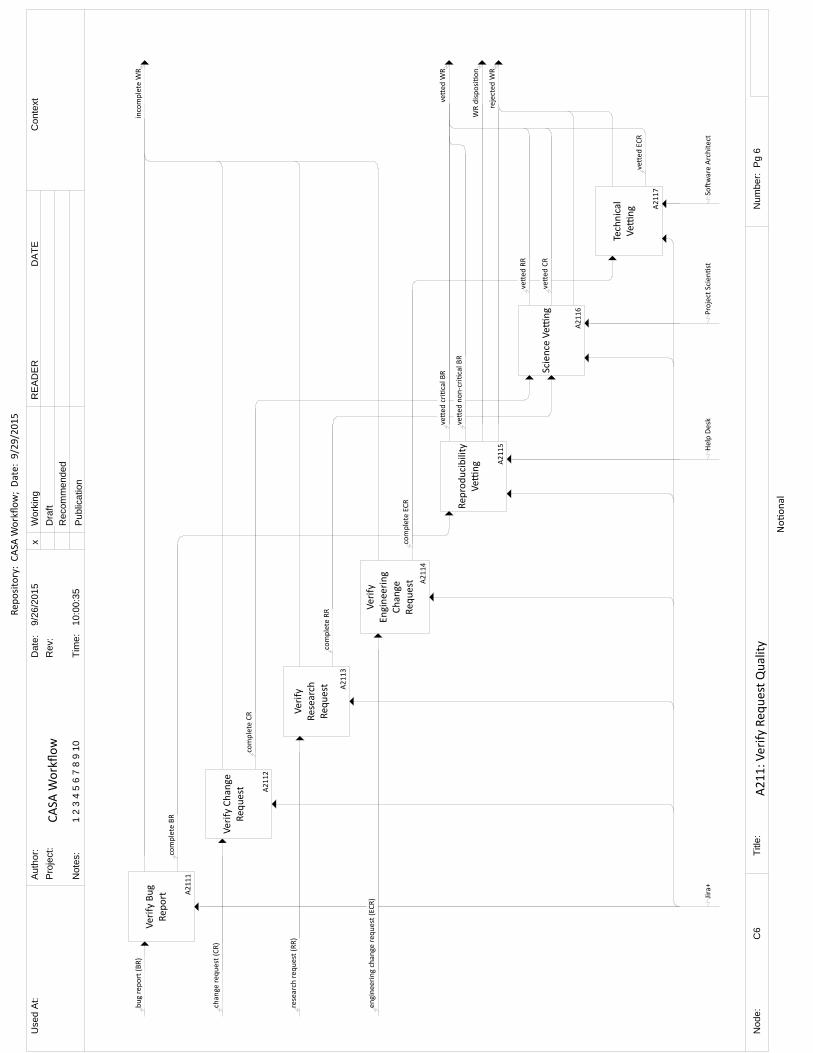
Use
d A
t:A
utho
r:
Pro
ject
:CASA
Workflo
w
Not
es:
1 2
3 4
5 6
7 8
9 10
Dat
e:9/
26/2
015
Tim
e:10
:00:
35
Rev
:
Wor
king
Dra
ftR
ecom
men
ded
Pub
licat
ion
xR
EA
DE
RD
AT
E
Nod
e:C
6T
itle:
A211: V
erify Req
uest Quality
Num
ber:
Pg
6
Con
text
Rep
ository: CASA
Workflo
w; Date: 9/29/2015
No
onal
Technical
Ve
ng A2117
Science Ve
ng
A2116
Rep
roducibility
Ve
ng A2115
Verify
Engineering
Change
Req
uest A2114
Verify
Research
Req
uest A2113
Verify Change
Req
uest A2112
Verify Bug
Rep
ort A
2111
veed ECR
veed CR
veed RR
veed non‐cri
cal BR
veed cri
cal BR
rejected W
R
WR disposi
on
veed W
R
engineering change req
uest (ECR)
complete ECR
research req
uest (RR)
complete RR
change req
uest (CR)
complete CR
bug report (BR)
complete BR
incomplete W
R
Soware Architect
Project Scien
stHelp Desk
Jira+

Use
d A
t:A
utho
r:
Pro
ject
:CASA
Workflo
w
Not
es:
1 2
3 4
5 6
7 8
9 10
Dat
e:9/
26/2
015
Tim
e:13
:05:
12
Rev
:
Wor
king
Dra
ftR
ecom
men
ded
Pub
licat
ion
xR
EA
DE
RD
AT
E
Nod
e:C
25T
itle:
A23: Sched
ule Project
Num
ber:
Pg
7
Con
text
Rep
ository: CASA
Workflo
w; Date: 9/29/2015
No
onal
Project Approval
A232
Defi
ne Project Tim
ebox
A231
WR disposi
on
assigned
WR
project
window of opportunity, meb
ox
CASA
Roadmap
Project M
anager
master sched
ule
resource calendar
Developer

Use
d A
t:A
utho
r:Eduardo M
iranda
Pro
ject
:CASA
Workflo
w
Not
es:
1 2
3 4
5 6
7 8
9 10
Dat
e:9/
26/2
015
Tim
e:15
:45:
02
Rev
:
Wor
king
Dra
ftR
ecom
men
ded
Pub
licat
ion
xR
EA
DE
RD
AT
E
Nod
e:C
29T
itle:
A24: Sched
ule Research Project
Num
ber:
Pg
8
Con
text
Rep
ository: CASA
Workflo
w; Date: 9/29/2015
No
onal
Research Project Approval
A242
Defi
ne Research Project Tim
ebox
A241
WR disposi
on
assigned
WR
research project
external resources availability
window of opportunity, meb
ox
CASA
Roadmap
Project M
anager
resource calendar
master sched
ule
Developer

Use
d A
t:A
utho
r:
Pro
ject
:CASA
Workflo
w
Not
es:
1 2
3 4
5 6
7 8
9 10
Dat
e:9/
26/2
015
Tim
e:15
:58:
17
Rev
:
Wor
king
Dra
ftR
ecom
men
ded
Pub
licat
ion
xR
EA
DE
RD
AT
E
Nod
e:C
7T
itle:
A3: C
ASA
& Pipeline Development
Num
ber:
Pg
9
Con
text
Rep
ository: CASA
Workflo
w; Date: 9/29/2015
No
onal
A35
Retrospec
ve
A35
A34
Plan & Execute
Research Project
A34
A33
Plan & Execute Project A33
A32
Execute Job
A32
A31
Fix Cri
cal Bug
A31
root causes
opportunies
observa
ons, opinions and insights
research project
research rep
ort
observa
ons, opinions and insights
project
smelly code
observa
ons, opinions and insights
job
bug report (BR)
crical BR
smelly code
observa
ons, opinions and insights
reporng
engineering change req
uest (ECR)
best pracces
Jira+
master sched
ule
reminder
design rules
Git
Jenkins
Sta
c Analysis Tool
design documenta
on

Use
d A
t:A
utho
r:
Pro
ject
:CASA
Workflo
w
Not
es:
1 2
3 4
5 6
7 8
9 10
Dat
e:9/
26/2
015
Tim
e:15
:59:
18
Rev
:
Wor
king
Dra
ftR
ecom
men
ded
Pub
licat
ion
xR
EA
DE
RD
AT
E
Nod
e:C
26T
itle:
A31: Fix Cri
cal Bug
Num
ber:
Pg
10
Con
text
Rep
ository: CASA
Workflo
w; Date: 9/29/2015
No
onal
Submit
Engineering
Change Req
uest
A317
Rep
air
A316
Localize Code to
be Corrected A315
Develop
Workaround A314
Recovery
Acc
ons
A313
Understand
Problem
A312
Rep
licate
Problem
A311
engineering change req
uest (ECR)
faulty code
smelly code
backup data
restored data
problem
latest configura
on
crical BR
replicated
BR
design rules
Jenkins
Sta
c Analysis Tool
design documenta
on
Git

Use
d A
t:A
utho
r:
Pro
ject
:CASA
Workflo
w
Not
es:
1 2
3 4
5 6
7 8
9 10
Dat
e:9/
26/2
015
Tim
e:15
:59:
21
Rev
:
Wor
king
Dra
ftR
ecom
men
ded
Pub
licat
ion
xR
EA
DE
RD
AT
E
Nod
e:C
24T
itle:
A32: Execute Job
Num
ber:
Pg
11
Con
text
Rep
ository: CASA
Workflo
w; Date: 9/29/2015
No
onal
Commit A
329
Validate A328
Review
A327
Documen
t
A326
Analyze A
325
Verify
A324
Develop
Tests
A323
Code
A322
Start Job A321
all pass
exploratory test case
bug report (BR)
issues
all pass
technical documenta
on
user documenta
on
code metrics & warnings
all pass
coverage
failed test case
all pass
test case
job
code
Project Scien
stSta
c Analysis Tool
design rules
Git
Developer
design documenta
on
reminder
master sched
ule

Use
d A
t:A
utho
r:
Pro
ject
:CASA
Workflo
w
Not
es:
1 2
3 4
5 6
7 8
9 10
Dat
e:9/
26/2
015
Tim
e:15
:59:
26
Rev
:
Wor
king
Dra
ftR
ecom
men
ded
Pub
licat
ion
xR
EA
DE
RD
AT
E
Nod
e:C
8T
itle:
A33: Plan & Execute Project
Num
ber:
Pg
12
Con
text
Rep
ository: CASA
Workflo
w; Date: 9/29/2015
No
onal
Track Against
Milestones A338
Develop Could
Have
A337
Develop
Should Have
A336
Develop M
ust
Have
A335
A334
Plan Project A334
Design
A333
Defi
ne
Features A332
Kick‐Off
Project
A331
status
design changes
all could have completed
design changes
all should have completed
design changes
all m
ust have completed
could have FE
should have FE
must have FE
design
Features (FE)
project
remminder
design rules design documenta
on
reminder
master sched
ule
CASA
Developmen
t/A31
CASA
Developmen
t/A31
CASA
Developmen
t/A31

Use
d A
t:A
utho
r:
Pro
ject
:CASA
Workflo
w
Not
es:
1 2
3 4
5 6
7 8
9 10
Dat
e:9/
26/2
015
Tim
e:12
:48:
10
Rev
:
Wor
king
Dra
ftR
ecom
men
ded
Pub
licat
ion
xR
EA
DE
RD
AT
E
Nod
e:C
9T
itle:
A334: Plan Project
Num
ber:
Pg
13
Con
text
Rep
ository: CASA
Workflo
w; Date: 9/29/2015
No
onal
Plan M
ilestones
A3344
Iden
fy Risks
A3343
Priori
ze Features A3342
Esmate Features A3341
milestones
risk m
iga
on acvi
es
design
could have FE
should have FE
must have FE
won't have FE
Features (FE)
esmated
FE

Use
d A
t:A
utho
r:
Pro
ject
:CASA
Workflo
w
Not
es:
1 2
3 4
5 6
7 8
9 10
Dat
e:9/
26/2
015
Tim
e:15
:59:
27
Rev
:
Wor
king
Dra
ftR
ecom
men
ded
Pub
licat
ion
xR
EA
DE
RD
AT
E
Nod
e:C
10T
itle:
A34: Plan & Execute Research Project
Num
ber:
Pg
14
Con
text
Rep
ository: CASA
Workflo
w; Date: 9/29/2015
No
onal
Write Change
Req
uest
A346
Write Rep
ort A345
Tollgate Review
A344
Develop M
inim
um
Viable Product A343
Form
ulate
Hypotheses
A342
Kick‐Off Research
Project
A341
research req
uest (RR)
change req
uest (CR)
research report
review hypotheses
con
nue
done
sponsor commitmen
t assessmen
t
term
inate
outcome
learning
verifica
on criteria
envisioned
capability
research project
Project M
anager
CASA
Group Leader
Git
Developer
Sponsor
Project Scien
st
design
documenta
on
reminder
master schedule

Use
d A
t:A
utho
r:
Pro
ject
:CASA
Workflo
w
Not
es:
1 2
3 4
5 6
7 8
9 10
Dat
e:9/
26/2
015
Tim
e:12
:38:
43
Rev
:
Wor
king
Dra
ftR
ecom
men
ded
Pub
licat
ion
xR
EA
DE
RD
AT
E
Nod
e:C
13T
itle:
A35: R
etrospec
veN
umbe
r: P
g 15
Con
text
Rep
ository: CASA
Workflo
w; Date: 9/29/2015
No
onal
Write Engineering
Change Req
uest
A354
Iden
fyOpportunites for
Improvemen
t A353
Defect Causal
Analysis
A352
Review Process
Perform
ance A
351
smelly code
engineering change req
uest (ECR)
completed CUS
opportunies
perform
ance m
easuremen
t
root causes
things that did not work
observa
ons, opinions and insights
things that work well
best pracces
ben
chmarks
organiza
onal policies
Jira+

Use
d A
t:A
utho
r:
Pro
ject
:CASA
Workflo
w
Not
es:
1 2
3 4
5 6
7 8
9 10
Dat
e:9/
26/2
015
Tim
e:15
:58:
05
Rev
:
Wor
king
Dra
ftR
ecom
men
ded
Pub
licat
ion
xR
EA
DE
RD
AT
E
Nod
e:C
20T
itle:
A4: Technical Deb
t Rep
ayment
Num
ber:
Pg
16
Con
text
Rep
ository: CASA
Workflo
w; Date: 9/29/2015
No
onal
Develop Test Cases A45
Refactoring
A44
Analyze Code
A43
Produce Design Rules
A42
Recover Design
A41
job
project
error prone code
highly vola
le code
low coverage code
design rules
design documen
taon
Git
Soware Architect
Reengineering Tool
CASA
Developmen
t/A32

Use
d A
t:A
utho
r:
Pro
ject
:CASA
Workflo
w
Not
es:
1 2
3 4
5 6
7 8
9 10
Dat
e:9/
26/2
015
Tim
e:13
:50:
02
Rev
:
Wor
king
Dra
ftR
ecom
men
ded
Pub
licat
ion
xR
EA
DE
RD
AT
E
Nod
e:C
19T
itle:
A5: B
uild
& Dep
loy
Num
ber:
Pg
17
Con
text
Rep
ository: CASA
Workflo
w; Date: 9/29/2015
No
onal
Write Bug
Rep
ort
A57
Release
A56
Dep
loy
A55
Run Automated
Tests
A54
Compile & Link
A53
Sta
c Analysis A52
Automate Tests
A51
bug report (BR)
release no
ce
pass
no pass
binary
pass
no pass
pass
no pass
test case
automated
test
managem
ent decision
Git
Jenkins

Use
d A
t:A
utho
r:Eduardo M
iranda
Pro
ject
:CASA
Workflo
w
Not
es:
1 2
3 4
5 6
7 8
9 10
Dat
e:9/
29/2
015
Tim
e:03
:42:
32
Rev
:
Wor
king
Dra
ftR
ecom
men
ded
Pub
licat
ion
xR
EA
DE
RD
AT
E
Nod
e:C
30T
itle:
A6: C
ASA
Steering
Num
ber:
Pg
18
Con
text
Rep
ository: CASA
Workflo
w; Date: 9/29/2015
No
onal
Prepare CASA
Roadmap
A63
Resolve Appeal
A62
Take Correc
ve Acon
A61
CASA
Roadmap
appeal
WR final disposi
on
reconsidered
WR
non‐compliance
balanced scorecard
completed CUS
correc
ve acon
resource calendar
master sched
ule

Use
d A
t:A
utho
r:
Pro
ject
:CASA
Workflo
w
Not
es:
1 2
3 4
5 6
7 8
9 10
Dat
e:9/
26/2
015
Tim
e:13
:56:
57
Rev
:
Wor
king
Dra
ftR
ecom
men
ded
Pub
licat
ion
xR
EA
DE
RD
AT
E
Nod
e:C
14T
itle:
A7: Q
uality Assurance
Num
ber:
Pg
19
Con
text
Rep
ository: CASA
Workflo
w; Date: 9/29/2015
No
onal
Measuremen
tProcess
A75
Communicate and
Ensure Resolu
on of
Non‐compliance Issues
A74
Monitor Customer
Sasfac
on
A73
Evaluate Process
Compliance
A72
Evaluate Work
Products
A71
measuremen
tsbalanced scorecard
open
acon item
s
escala
on
correc
ve acon
completed CUS
CASA
user survey (CUS)
opportunies
root causes
process traces
non‐compliance
work products
processes
Git

76
Appendix D. Definition of Done
This appendix presents a notional DoD for a “Job”. It is intended to be used as example as not as a
concrete recommendation. Similarly the CDG should define DoD for projects and other artifacts as they
see fit.
Once defined, DoDs strict application will be critical to overcoming the concerns raised by the Pipeline
Group about the condition the software will be in when moving from a discrete to a continuous delivery
mode.
Example:
Code produced (all ‘to do’ items in code completed)
Code commented, checked in and run against current version in source control
Peer reviewed (or produced with pair programming) and meeting development standards
Builds without errors
Unit tests written and passing
Deployed to system test environment and passed system tests
Passed UAT (User Acceptance Testing) and signed off as meeting requirements
Achieved X% branch coverage
Any build/deployment/configuration changes implemented/documented/communicated
Relevant documentation/diagrams produced and/or updated
Tasks closed in Jira

77
Appendix E. Buffered Moscow Rules
This appendix depicts a planning method for time boxed projects. It is intended to be used as example
and not as a concrete recommendation.
Eduardo Miranda© 2011
TIME BOXING PLANNING: BUFFERED
MOSCOW RULES
EDUARDO MIRANDA, INSTITUTE FOR SOFTWARE RESEARCH, CARNEGIE MELLON UNIVERSITY, SEPTEMBER 2011
Keywords: Time boxing planning, prioritization rules, release planning, agile, incremental delivery,
requirements prioritization, design to schedule
ABSTRACT
Time boxing is a management technique which prioritizes schedule over deliverables but time boxes
which are merely a self, or an outside, imposed target without agreed partial outcomes and justified
certainty are at best, an expression of good will on the part of the team. This essay proposes the use of a
modified set of Moscow rules which accomplish the objectives of prioritizing deliverables and providing
a degree of assurance as a function of the uncertainty of the underlying estimates.
INTRODUCTION
Time boxing is a management technique which prioritizes schedule over deliverables. This means that if
during the execution of the task it is anticipated that all requested deliverables will not be ready by a set
completion date, the scope of the work will be reduced so that a smaller, yet still useful, output is
produced by such date. The two dimensions of the time box are the length of time it is given and the
resources available during that time. The time box concept can be applied to individual tasks and single
iterations but the focus of this proposal is in larger aggregates, such as a release or a project,
culminating in the delivery of an agreed functionality to a customer.

Eduardo Miranda© 2011
To be effective, time boxing requires that (Miranda, 2002):
1. The features or user requirements1 that make up the total delivery are grouped into functionally
complete subsets;
2. The subsets are prioritized so it is clear which requirements should be implemented first and
which ones could be eliminated if there is not enough time to complete all of them; and
3. Reasonable assurance is provided to the customer about the feasibility of a given subset within
the imposed frame
Time boxes which are merely a self, or an outside, imposed target without agreed partial outcomes and
justified certainty are at best, an expression of good will on the part of the team.
Prioritization is traditionally made by asking the customer to rank his or her preferences into a series of
categories such as “Must have”, “Should have”, “Could have” or “Won’t have” where the “Must have”
category contains all requirements that must be satisfied in the final delivery for the solution to be
considered a success. The “Should have” represents high‐priority items that should be included in the
solution if possible. The “Could have” corresponds to those requirement which are considered desirable
but not necessary. They will be included if there is any time left after developing the previous two.
“Won’t have” are used to designate requirements that will not be implemented in a given time box, but
may be considered for the future. These categories are commonly known by the acronym “Moscow”
(Stapleton, 2003). Less used techniques include the pairwise comparisons, cumulative voting, top ten
requirements and EVOLVE (Berander & Andrews, 2005).
With the exception of EVOLVE (Greer & Ruhe, 2004) which uses a complex search procedure to
maximize value within the constraints imposed by the available resources; all the techniques above
suffer from the same problem: they are either unconstrained or arbitrarily constrained. For example in
the “top ten” technique the “must have” would be limited to the 10 more important requirements. Why
10? Why not eleven or twelve or nine? This lack of constraints means that in general, as long as the
aggregated effort is within the project budget there is no limit to the number of requirements that are
assigned to the “must have” category with which the prioritization process ends up not prioritizing
anything at all.
In this article we describe a simple requirement prioritization method that: 1) Redefines the MOSCOW
categories in terms of the team’s ability to complete the requirements assigned to them; and 2)
Constrains the number of requirements that the customer can allocate to each category as a function of
the uncertainty of the estimates which makes it possible to give the sponsor certain reassurances with
regards to their achievability or not. The MOSCOW categories are redefined as follows:
1. Must Have: Those features that the project, short of a calamity, would be able to deliver within
the defined time box
1 These two terms will be used loosely and alternatively to refer to a discrete capability requested by the sponsor of the work

Eduardo Miranda© 2011
2. Should Have: Those features that have a fair chance of being delivered within the defined time
box
3. Could Have: Those features that the project could deliver within the defined time box if
everything went extraordinarily well, i.e. if there were no hiccups in the development of
requirements assigned to higher priority categories
4. Won’t have features, those for which there is not enough budget to develop them
Therefore, the fitting of requirements into these categories is not an a priori decision but rather a
consequence of what the development team believes can be accomplished under the specific project
context and budget.
In the past I have associated a delivery probability of 90, 45 and 20% with each of the categories, but
this quantification it is only possible if one is willing to make assumptions about the independence or
covariance of the actual efforts, the number of requirements included in each category and the type of
distributions underlying each estimate; or to use a method such as Monte Carlo simulation to expose
the distribution of the total effort for each category. If we are not willing to make this, quoting specific
numbers is just an analogy, all we can justifiable say is that the likelihood of delivering all requirements
in the “must have” category would roughly double the likelihood of those in the “should have” category
and quadruple that of those in the “could have” one.
THE IDEA
The process requires that each feature or requirement to be developed has a two points estimate2: a
normal completion effort3 and a safe completion one. The normal completion effort is that, which in the
knowledge of the estimator has a fair chance of being enough to develop the estimated feature while
the safe estimate is that which will be sufficient to do the work most of the time but in a few really bad
cases.
If we wanted to be reassured of being able to deliver all features under most circumstances we would
need to plan for the worst case, which means scheduling all deliverables using their safe estimate. This,
more likely than not, will exceed the boundaries of the time box4. See Figure 1.a.
It is clear that by scheduling features at the safe level, the most work we can accommodate within the
time box boundaries is that depicted by the patterned area in Figure 1.b. So for the “must have”
category the customer must select, from among all requirements, those which are more important for
him until exhausting the number of development hours available while scheduling them at the safe
2 More sophisticated approaches such as Statistically Planned Incremental Deliveries – SPID (Miranda, 2002) will require three points estimates and the specification of an underlying distribution 3 As I did in the redefining of the MOSCOW categories in this article I am avoiding the temptation of calling these estimates the 50% and the 90% probability estimates to prevent giving a false sense of mathematical exactness, that will require the making of additional assumptions or an analysis that might not be justified by the practical impact of the added accuracy and precision. 4 If a single project had to ensure against all possible risks and uncertainty, its price would be prohibitive (Kitchenham & Linkman, 1997)

Eduardo Miranda© 2011
effort level. This is the constraint missing in other prioritization methods and the key to provide a high
level of confidence, in spite of the uncertainty of the estimates and the speed of execution, in the
delivery of features in this category.
Once the “must have” requirements have been selected, we will re‐schedule them using their normal
estimates, see figure 1.c, and reserve the difference between the two effort levels as a buffer to protect
their delivery. We will repeat the process for the “should have” and “could have” requirements using
the size of the buffer protecting the previous category as the initial budget for the current one, see
figure 1.d. The requirements that could not be accommodated in any category at their safe level
become the “won’t have”s.
Figure 1 How the method works
We can see now why we said at the beginning of this essay that the “must have” category will have
double the likelihood of being completed of the “should have” and quadruple that of the “could have”.
We are almost certain that all the requirements in the “must have” category can be completed within
the time box because a requirement was only included in it if there was enough room to develop it
under a worst case assumption. The “should have” category also have their requirements scheduled at
the safe level, but with respect to the overall time box this level of confidence is contingent on the sum
Time box
Development activities scheduled at their safe level
Must have release at safe level Lower priority deliverables
Must have using the normal estimate
Should have at normal
Could have at safe
Won’t have
Startup activities Other support and management activities
Startup activities Other support and management activities
Startup activities Other support and management activities
Buffer
Must have using the normalestimate
Startup activities Other support and management activities
Buffer
Buffer
a.
b.
c.
d. Must have using the normal
estimate
Should have at safe level Lower priority deliverables
Startup activities Other support and management activities
Buffer
e.

Eduardo Miranda© 2011
of the actual efforts spent on all the requirements in the “must have” subset being equal or less than the
sum of their normal development times. This roughly halves the likelihood of completing all “should
have” requirements within the time box. Similarly the likelihood of completing all the “could have”
would be half of that of delivering all the “should have” or a quarter of the “must have”.
A NUMERICAL EXAMPLE
Table 1 shows the backlog for an imaginary project with a total budget (time box) of 180hrs. Assuming
that the startup, and the support and management activities require 60hrs. leave us with a development
budget of 120 hrs. The table lists the name of the features, the normal and the safe estimates and the
name of other requirements or features in which the current one depends on. For example feature “H”
will have a normal estimate of 10 hours, a safe estimate of 20 hours and depends on “J” and “K”,
meaning that these two features must be present for “H” to provide any business value.
Table 1 Product backlog
Let’s assume that from a pure business
perspective the preferences of the project
sponsor are: F, D, A, G, K, E, L, J, H, I, B, C. In
a real project this choices will be made
during the prioritization meeting.
In our example, the first requirement to be
selected for the “must have” category
would be requirement “F”, applying the
process described below we have:
120 6 114
Successive requirements are selected as per table 2. Notice that feature “G” cannot be included in the
“must have” subset at the safe level because it does not fit into the available budget. At this point the
customer must decide whether to resign “G” to another category, if possible, or rearrange the previous
selection. For the sake of the example let’s assume requirement “G” is passed on, and the customer
chooses “K” which follows in his rank of preferences and is schedulable in the available budget.
Features Normal Estimate Safe Estimate Dependencies
A 20 40 B, C B 7 9 C 20 30 D 5 7 E E 6 7 F 5 6 G 20 40 H 10 20 J, K I 15 30 J 12 15 K 8 10 L 10 18

Eduardo Miranda© 2011
Table 2 Assigning requirements to the “must have” category
Features Reason for selection
F Customer preference 120 6 114
D, E Customer preference, Dependency
114 14 100
A, B, C Customer preference, Dependency
100 79 21
G Customer preference 21 40 ‐19
K Customer preference 21 10 11
After including “K” there is no other requirement that can be included in the “must have” category, so
requirements F, D, E, A, B, C, and K are re‐schedule at their normal level:
∈ , , , , , ,
5 5 6 20 7 20 8
71
120 71 49
The process is now repeated using the as the available budget for the “should have”
CATEGORY, see table 3, and the for the “could have”. See table 4.
Table 3 Assigning requirements to the “should have” category
Features Reason for selection
G Customer preference 49 40 9
Table 4 Assigning requirements to the “could have” category
Features Reason for selection
L Customer preference 29 18 11
After including “L” nothing more could be included in the available effort at the safe estimate level and
in consequence “H”, “I” and “J” are declared “won’t have”.

Eduardo Miranda© 2011
The final subsets are:
Must have: F, D, E, A, B, C, K
Should have: G
Could have: L
Won’t have: H, I, J
EXECUTION
Figure 2 shows the initial plan resulting from the prioritization process. Now imagine that during the
execution of the project feature “A” takes 40hrs, its worst case, instead of the 20 allocated to it in the
plan. This will push the development of features “G” and “L” to the right. This would leave us with 29hrs
to develop “G”, 9 more than the 20hrs estimated at 50%, so one can say there still is a fair chance the
customer will get it. If “G” takes 20 hours the budget remaining in the box will be 9 hours, one less than
the 10 estimated at 50%, so in this case the chance of the customer getting L would be slim. See Figure
3.
Figure 2 Original plan. Time box = 180 hrs, Startup and other support and management activities 60 hrs, development budget 120 hrs
Figure 3 Must have release is delayed because “A” takes longer than the scheduled budget
Time box
G
L H, I, J
F, D, E, A, B, C, K
Startup activities Other support and management activities
49 hrs
29 hrs
29 hrsG
Time box
L
F, D, E, A, B, C, K
Startup activities Other support and management activities
49 hrs
Delay due to A

Eduardo Miranda© 2011
DEALING WITH CHANGES AND DEFECTS
Changes are natural. When a change occurs it should be ranked against current priorities and if accepted
it will be at the expense of an already planned requirement or by changing the time box itself.
With respect to defects a sensible strategy is to fix all critical and major defects within the time allocated
at the subset in which they are discovered, postponing minor defects to the end of the project and
giving the customer the choice between fixing the problems and developing additional functionality.
BUSINESS IMPLICATIONS
It is obvious that acknowledging from the very start of the project that the customer might not receive
everything requested requires a very different communication, and perhaps marketing, strategy from
that of a project that promises to do it, even when nobody believes it will do it.
The premise, in which the method is based, is that businesses are better off when they know what could
realistically be expected than when they are promised the moon, but no assurances are given with
respect as to when they could get it.
To be workable for both parties, the developer and the sponsor, a contract must incorporate the notion
that an agreed partial delivery is an acceptable, although not preferred, outcome. A contract that
offloads all risk in one of the parties would either be prohibitive or unacceptable to the other. The
concept of agreed partial deliveries could adopt many forms. For example the contract could establish a
basic price for the “must have” set with increasingly higher premiums for the “should have” and “could
have” releases. Conversely the contract could propose a price for all deliverables and include penalties
or discounts if the lower priority releases are not delivered. The advantage for the project sponsor is
that, whatever happens, he can rest assured that he will get a working product with an agreed subset of
the total functionality by the end of the project on which he can base his own plans.
A similar idea could be applied to any reward for the people working in the project. No reward will be
associated with delivering the “must have” release since the team members are simply doing their jobs.
Subsequent releases will result in increased recognition of the extra effort put into the task. The relative
delivery likelihood associated with each release could be used to calculate the reward’s expected value.
SUMMARY
We have presented a simple prioritization procedure that can be applied to the ranking of requirements
at the release as well as the project level.
The procedure does not only captures customer preferences, but by constraining the number of
features in the “must have” set as a function of the uncertainty of the underlying estimates, is able to
offer project sponsors a high degree of reassurance in regards to the delivered of an agreed level of
software functionality by the end of the time box.
Eduardo Miranda© 2011
This simplicity is not free. It comes at the expense of the claims we can make about the likelihood of
delivering a given functionality and a conservative buffer. Users seeking to make more definitive
statements than “short of a calamity” or optimize the buffer size should consider the use of a more
sophisticated approach such like the one described in Planning and Executing Time Bound Projects
(Miranda, 2002) which requires considerably more information and an understanding of the problems
associated with the elicitation of probabilities.
BIBLIOGRAPHY
Berander, P., & Andrews, A. (2005). Requirements prioritization. In C. W. A. Aurum, Engineering and
Managing Software Requirements. Berlin: Springer Verlag.
Greer, D., & Ruhe, G. (2004). Software release planning: an evolutionary and iterative approach.
Information and Software Technology, 46(4).
Kitchenham, B., & Linkman, S. (1997, May). Estimates, Uncertainty and Risk. IEEE Software.
Miranda, E. (2002, March). Planning and Executing Time Bound Projects. IEEE Computer.
Stapleton, J. (2003). DSDM Business Focused Development, 2nd ed. London: Addison Wesley.

87
Appendix F. Technology Readiness Levels
TRL Definition Description Supporting Information
1 Basic principles observed and reported.
Lowest level of software technology readiness. A new software domain is being investigated by the basic research community. This level extends to the development of basic use, basic properties of software architecture, mathematical formulations, and general algorithms.
Basic research activities, research articles, peer reviewed white papers, point papers, early lab model of basic concept may be useful for substantiating the TRL.
2 Technology concept and/or application formulated.
Once basic principles are observed, practical applications can be invented. Applications are speculative, and there may be no proof or detailed analysis to support the assumptions. Examples are limited to analytic studies using synthetic data.
Applied research activities, analytic studies, small code units, and papers comparing competing technologies.
3 Analytical and experimental critical function and/or characteristic proof of concept.
Active R&D is initiated. The level at which scientific feasibility is demonstrated through analytical and laboratory studies. This level extends to the development of limited functionality environments to validate critical properties and analytical predictions using non‐ integrated software components and partially representative data.
Algorithms run on a surrogate processor in a laboratory environment, instrumented components operating in a laboratory environment, laboratory results showing validation of critical properties.
4 Module and/or subsystem validation in a laboratory environment (i.e., software prototype development environment).
Basic software components are integrated to establish that they will work together. They are relatively primitive with regard to efficiency and robustness compared with the eventual system. Architecture development initiated to include interoperability, reliability, maintainability, extensibility, scalability, and security issues. Emulation with current/legacy elements as appropriate. Prototypes developed to demonstrate different aspects of eventual system.
Advanced technology development, stand‐alone prototype solving a synthetic full‐scale problem, or standalone prototype processing fully representative data sets.
5 Module and/or subsystem validation in a relevant environment.
Level at which software technology is ready to start integration with existing systems. The prototype implementations conform to target environment/interfaces. Experiments with realistic problems. Simulated interfaces to existing systems. System software architecture established. Algorithms run on a processor(s) with characteristics expected in the operational environment.
Software architecture diagram around technology element with critical performance requirements defined. Processor selection analysis, Simulation/Stimulation (Sim/Stim) Laboratory buildup plan. Software placed under configuration management. Commercial‐off‐the‐ shelf/government‐off‐the‐shelf (COTS/GOTS) components in the system software architecture are identified.
6 Module and/or subsystem validation in a relevant end‐to‐ end environment.
Level at which the engineering feasibility of a software technology is demonstrated. This level extends to laboratory prototype implementations on full‐scale realistic problems in which the software technology is partially integrated with existing hardware/software systems.
Results from laboratory testing of a prototype package that is near the desired configuration in terms of performance, including physical, logical, data, and security interfaces. Comparisons between tested environment andoperational environment analytically understood. Analysis and test measurements quantifying contribution to system‐wide requirements such as throughput, scalability, and reliability. Analysis of human‐computer (user environment) begun.

7 System prototype demonstration in an operational, high‐fidelity environment.
Level at which the program feasibility of a software technology is demonstrated. This level extends to operational environment prototype implementations, where critical technical risk functionality is available for demonstration and a test in which the software technology is well integrated with operational hardware/software systems.
Critical technological properties are measured against requirements in an operational environment.
8 Actual system completed and mission qualified through test and demonstration in an operational environment.
Level at which a software technology is fully integrated with operational hardware and software systems. Software development documentation is complete. All functionality tested in simulated and operational scenarios.
Published documentation and product technology refresh build schedule. Software resource reserve measured and tracked.
9 Actual system proven through successful mission‐proven operational capabilities.
Level at which a software technology is readily repeatable and reusable. The software based on the technology is fully integrated with operational hardware/software systems. All software documentation verified. Successful operational experience. Sustaining software engineering support in place. Actual system.
Production configuration management reports. Technology integrated into a reuse "wizard."