recommendations for preparing the criticality safety ... › docs › default-source › ... ·...
TRANSCRIPT

NUREG/CR-5661ORNL/TM-11936
Recommendations for Preparing the Criticality Safety Evaluationof Transportation Packages
Prepared byH. R. Dyer, C. V. Parks
Oak Ridge National Laboratory
Prepared forU.S. Nuclear Regulatory Commission

AVAILABILITY NOTICEAvailability of Reference Materials Cited in NRC Publications
NRC publications in the NUREG series, NRCregulations, and Title 10, Energy, of the Code ofFederal Regulations, may be purchased from one ofthe following sources:
1. The Superintendent of DocumentsU.S. Government Printing OfficeP.O. Box 37082Washington, DC 20402-9328<http://www.access.gpo.gov/su_docs>202-512-1800
2. The National Technical Information ServiceSpringfield, VA 22161-0002<http://www.fedworld.gov/onow>703-487-4650
The NUREG series comprises (1) brochures(NUREG/BR-XXXX), (2) proceedings of conferences(NUREG/CP-XXXX), (3) reports resulting frominternational agreements (NUREG/IA-XXXX),(4) technical and administrative reports and books[(NUREG-XXXX) or (NUREG/CR-XXXX], and(5) compilations of legal decisions and orders of theCommission and Atomic and Safety Licensing Boardsand of Office Directors’ decisions under Section 2.206of NRC’s regulations (NUREG-XXXX).
A single copy of each NRC draft report is availablefree, to the extent of supply, upon written request asfollows:
Address: Office of the Chief Information Officer Reproduction and Distribution
Services SectionU.S. Nuclear Regulatory CommissionWashington, DC 20555-0001
E-mail: <[email protected]>Facsimile: 301-415-2289
A portion of NRC regulatory and technical informationis available at NRC’s World Wide Web site:
<http://www.nrc.gov>
All NRC documents released to the public are availablefor inspection or copying for a fee, in paper, microfiche,or, in some cases, diskette, from the Public DocumentRoom (PDR):
NRC Public Document Room2120 L Street, N.W., Lower LevelWashington, DC 20555-0001 <http://www.nrc.gov/NRC/PDR/pdr1.htm>1-800-397-4209 or locally 202-634-3273
Microfiche of most NRC documents made publiclyavailable since January 1981 may be found in the LocalPublic Document Rooms (LPDRs) located in the vicinityof nuclear power plants. The locations of the LPDRsmay be obtained from the PDR (see previousparagraph) or through:
<http://www.nrc.gov/NRC/NUREGS/SR1350/V9/lpdr.html>
Publicly released documents include, to name a few,NUREG-series reports; Federal Register notices;applicant, licensee, and vendor documents andcorrespondence; NRC correspondence and internalmemoranda; bulletins and information notices;inspection and investigation reports; licensee eventreports; and Commission papers and their attachments.
Documents available from public and special technicallibraries include all open literature items, such as books,journal articles, and transactions, Federal Registernotices, Federal and State legislation, and congressionalreports. Such documents as theses, dissertations,foreign reports and translations, and non-NRCconference proceedings may be purchased from theirsponsoring organization.
Copies of industry codes and standards used in asubstantive manner in the NRC regulatory process aremaintained at the NRC Library, Two White Flint North,11545 Rockville Pike, Rockville, MD 20852-2738. Thesestandards are available in the library for reference useby the public. Codes and standards are usuallycopyrighted and may be purchased from the originatingorganization or, if they are American NationalStandards, from—
American National Standards Institute11 West 42nd StreetNew York, NY 10036-8002 <http://www.ansi.org>212-642-4900
DISCLAIMERThis report was prepared as an account of work sponsoredby an agency of the United States Government. Neither theUnited States Government nor any agency thereof, nor anyof their employees, makes any warranty, expressed orimplied, or assumes any legal liability or responsibility for
any third party’s use, or the results of such use, of anyinformation, apparatus, product, or process disclosed in thisreport, or represents that its use by such third party would notinfringe privately owned rights.

NUREG/CR-5661ORNL/TM-11936
Recommendations for Preparing the Criticality Safety Evaluationof Transportation Packages
Manuscript Completed: March 1997Date Published: April 1997
Prepared byH. R. Dyer, C. V. Parks
Oak Ridge National LaboratoryManaged by Lockheed Martin Energy Research Corp.Oak Ridge, TN 37831-6370
M. G. Bailey, NRC Project Manager
Prepared forSpent Fuel Project OfficeOffice of Nuclear Material Safety and SafeguardsU.S. Nuclear Regulatory CommissionWashington, DC 20555-0001NRC JCN No. B0009


NUREG/CR-5661iii
ABSTRACT
This report provides recommendations on preparing the criticality safety section of an application for approval ofa transportation package containing fissile material. The analytical approach to the evaluation is emphasized ratherthan the performance standards that the package must meet. Where performance standards are addressed, thisreport incorporates the requirements of 10 CFR Part 71.

NUREG/CR-5661v
CONTENTSPage
ABSTRACT . . . . . . . . . . . . . . . . . . . . . . . . . . . . . . . . . . . . . . . . . . . . . . . . . . . . . . . . . . . . . . . . . . . . . . . . . . iii
LIST OF FIGURES . . . . . . . . . . . . . . . . . . . . . . . . . . . . . . . . . . . . . . . . . . . . . . . . . . . . . . . . . . . . . . . . . . . . vii
LIST OF TABLES . . . . . . . . . . . . . . . . . . . . . . . . . . . . . . . . . . . . . . . . . . . . . . . . . . . . . . . . . . . . . . . . . . . . viii
ACKNOWLEDGMENTS . . . . . . . . . . . . . . . . . . . . . . . . . . . . . . . . . . . . . . . . . . . . . . . . . . . . . . . . . . . . . . . . ix
1 INTRODUCTION . . . . . . . . . . . . . . . . . . . . . . . . . . . . . . . . . . . . . . . . . . . . . . . . . . . . . . . . . . . . . . . . . . . 11.1 BACKGROUND . . . . . . . . . . . . . . . . . . . . . . . . . . . . . . . . . . . . . . . . . . . . . . . . . . . . . . . . . . . . . 11.2 PURPOSE AND SCOPE . . . . . . . . . . . . . . . . . . . . . . . . . . . . . . . . . . . . . . . . . . . . . . . . . . . . . . . 11.3 SUMMARY RECOMMENDATIONS . . . . . . . . . . . . . . . . . . . . . . . . . . . . . . . . . . . . . . . . . . . . . 1
2 PACKAGE DESCRIPTION . . . . . . . . . . . . . . . . . . . . . . . . . . . . . . . . . . . . . . . . . . . . . . . . . . . . . . . . . . . . 32.1 CONTENTS . . . . . . . . . . . . . . . . . . . . . . . . . . . . . . . . . . . . . . . . . . . . . . . . . . . . . . . . . . . . . . . . 32.2 PACKAGING . . . . . . . . . . . . . . . . . . . . . . . . . . . . . . . . . . . . . . . . . . . . . . . . . . . . . . . . . . . . . . . 32.3 SPECIFICATION OF TRANSPORT INDEX . . . . . . . . . . . . . . . . . . . . . . . . . . . . . . . . . . . . . . . 4
3 CRITICALITY SAFETY ANALYSIS MODELS . . . . . . . . . . . . . . . . . . . . . . . . . . . . . . . . . . . . . . . . . . . . 53.1 GENERAL . . . . . . . . . . . . . . . . . . . . . . . . . . . . . . . . . . . . . . . . . . . . . . . . . . . . . . . . . . . . . . . . . 5
3.1.1 Sketches . . . . . . . . . . . . . . . . . . . . . . . . . . . . . . . . . . . . . . . . . . . . . . . . . . . . . . . . . . . . 53.1.2 Dimensions . . . . . . . . . . . . . . . . . . . . . . . . . . . . . . . . . . . . . . . . . . . . . . . . . . . . . . . . . . 53.1.3 Materials . . . . . . . . . . . . . . . . . . . . . . . . . . . . . . . . . . . . . . . . . . . . . . . . . . . . . . . . . . . 63.1.4 Differences Between the Models and the Actual Package Configuration . . . . . . . . . . . . . 7
3.2 CONTENTS MODELS . . . . . . . . . . . . . . . . . . . . . . . . . . . . . . . . . . . . . . . . . . . . . . . . . . . . . . . . 73.3 SINGLE-PACKAGE MODELS . . . . . . . . . . . . . . . . . . . . . . . . . . . . . . . . . . . . . . . . . . . . . . . . . . 83.4 PACKAGE ARRAY MODELS . . . . . . . . . . . . . . . . . . . . . . . . . . . . . . . . . . . . . . . . . . . . . . . . . 8
4 METHOD OF ANALYSIS . . . . . . . . . . . . . . . . . . . . . . . . . . . . . . . . . . . . . . . . . . . . . . . . . . . . . . . . . . . . 114.1 COMPUTER CODE SYSTEM . . . . . . . . . . . . . . . . . . . . . . . . . . . . . . . . . . . . . . . . . . . . . . . . . 114.2 CROSS SECTIONS AND CROSS-SECTION PROCESSING . . . . . . . . . . . . . . . . . . . . . . . . . 124.3 CODE INPUT . . . . . . . . . . . . . . . . . . . . . . . . . . . . . . . . . . . . . . . . . . . . . . . . . . . . . . . . . . . . . . 124.4 ADEQUACY OF CALCULATION . . . . . . . . . . . . . . . . . . . . . . . . . . . . . . . . . . . . . . . . . . . . . . 13
5 VALIDATION OF CALCULATIONAL METHOD . . . . . . . . . . . . . . . . . . . . . . . . . . . . . . . . . . . . . . . . . 155.1 SELECTION OF CRITICAL EXPERIMENTS . . . . . . . . . . . . . . . . . . . . . . . . . . . . . . . . . . . . . 155.2 ESTABLISHMENT OF BIAS AND UNCERTAINTY . . . . . . . . . . . . . . . . . . . . . . . . . . . . . . . . 165.3 ESTABLISHMENT OF RANGE OF APPLICABILITY . . . . . . . . . . . . . . . . . . . . . . . . . . . . . . . 175.4 ESTABLISHMENT OF ACCEPTANCE CRITERIA . . . . . . . . . . . . . . . . . . . . . . . . . . . . . . . . . 18
6 CRITICALITY CALCULATIONS AND RESULTS . . . . . . . . . . . . . . . . . . . . . . . . . . . . . . . . . . . . . . . . . 216.1 SINGLE PACKAGE . . . . . . . . . . . . . . . . . . . . . . . . . . . . . . . . . . . . . . . . . . . . . . . . . . . . . . . . . 216.2 EVALUATION OF PACKAGE ARRAYS . . . . . . . . . . . . . . . . . . . . . . . . . . . . . . . . . . . . . . . . . 236.3 RELATING ANALYSES TO TRANSPORT INDEX . . . . . . . . . . . . . . . . . . . . . . . . . . . . . . . . 27
NUREG/CR-5661 vi
7 SUMMARY . . . . . . . . . . . . . . . . . . . . . . . . . . . . . . . . . . . . . . . . . . . . . . . . . . . . . . . . . . . . . . . . . . . . . . . . 29
8 REFERENCES . . . . . . . . . . . . . . . . . . . . . . . . . . . . . . . . . . . . . . . . . . . . . . . . . . . . . . . . . . . . . . . . . . . . . 31
APPENDIX A. EXAMPLE OF CALCULATIONAL MODELS AND RESULTS . . . . . . . . . . . . . . . . . . . . 33A.1 GENERAL DESCRIPTION (Example) . . . . . . . . . . . . . . . . . . . . . . . . . . . . . . . . . . . . . . . . . . . 33A.2 PACKAGE DESCRIPTION . . . . . . . . . . . . . . . . . . . . . . . . . . . . . . . . . . . . . . . . . . . . . . . . . . . 33
A.2.1 CONTENTS . . . . . . . . . . . . . . . . . . . . . . . . . . . . . . . . . . . . . . . . . . . . . . . . . . . . . . . 34A.2.2 PACKAGING . . . . . . . . . . . . . . . . . . . . . . . . . . . . . . . . . . . . . . . . . . . . . . . . . . . . . . 34
A.2.2.1 Inner Container Assembly . . . . . . . . . . . . . . . . . . . . . . . . . . . . . . . . . . . . . . 34A.2.2.2 Inner Container . . . . . . . . . . . . . . . . . . . . . . . . . . . . . . . . . . . . . . . . . . . . . . 34A.2.2.3 Drum . . . . . . . . . . . . . . . . . . . . . . . . . . . . . . . . . . . . . . . . . . . . . . . . . . . . . . 36
A.3 CRITICALITY SAFETY ANALYSIS MODELS . . . . . . . . . . . . . . . . . . . . . . . . . . . . . . . . . . . 36A.3.1 GENERAL MODEL . . . . . . . . . . . . . . . . . . . . . . . . . . . . . . . . . . . . . . . . . . . . . . . . . 36
A.3.1.1 Dimensions . . . . . . . . . . . . . . . . . . . . . . . . . . . . . . . . . . . . . . . . . . . . . . . . . 36A.3.1.2 Materials . . . . . . . . . . . . . . . . . . . . . . . . . . . . . . . . . . . . . . . . . . . . . . . . . . . 36A.3.1.3 Models&Actual Package Differences . . . . . . . . . . . . . . . . . . . . . . . . . . . . . . 39
A.3.2 CONTENTS MODEL . . . . . . . . . . . . . . . . . . . . . . . . . . . . . . . . . . . . . . . . . . . . . . . . 39A.3.3 SINGLE PACKAGES . . . . . . . . . . . . . . . . . . . . . . . . . . . . . . . . . . . . . . . . . . . . . . . . 39A.3.4 PACKAGE ARRAYS . . . . . . . . . . . . . . . . . . . . . . . . . . . . . . . . . . . . . . . . . . . . . . . . 40
A.4 METHOD OF ANALYSIS . . . . . . . . . . . . . . . . . . . . . . . . . . . . . . . . . . . . . . . . . . . . . . . . . . . . 41A.4.1 COMPUTER CODE SYSTEM . . . . . . . . . . . . . . . . . . . . . . . . . . . . . . . . . . . . . . . . . 41A.4.2 CROSS SECTIONS AND CROSS-SECTION PROCESSING . . . . . . . . . . . . . . . . . 42A.4.3 CODE INPUT . . . . . . . . . . . . . . . . . . . . . . . . . . . . . . . . . . . . . . . . . . . . . . . . . . . . . . 42A.4.4 CONVERGENCE OF CALCULATIONS . . . . . . . . . . . . . . . . . . . . . . . . . . . . . . . . . 42
A.5 VALIDATION OF CALCULATION METHOD . . . . . . . . . . . . . . . . . . . . . . . . . . . . . . . . . . . . 44A.6 CRITICALITY CALCULATIONS AND RESULTS . . . . . . . . . . . . . . . . . . . . . . . . . . . . . . . . 44
A.6.1 SINGLE PACKAGE . . . . . . . . . . . . . . . . . . . . . . . . . . . . . . . . . . . . . . . . . . . . . . . . . 44A.6.2 PACKAGE ARRAYS . . . . . . . . . . . . . . . . . . . . . . . . . . . . . . . . . . . . . . . . . . . . . . . . 45A.6.3 TRANSPORTATION INDEX . . . . . . . . . . . . . . . . . . . . . . . . . . . . . . . . . . . . . . . . . . 47
NUREG/CR-5661vii
LIST OF FIGURES
Figure Page
1 Typical plots of array keff vs interspersed water moderator density . . . . . . . . . . . . . . . . . . . . . . . . . . . . . 25
A.1 Axial cross section of the single-package model . . . . . . . . . . . . . . . . . . . . . . . . . . . . . . . . . . . . . . . . . . . 37
A.2 Radial cross section of single-package model . . . . . . . . . . . . . . . . . . . . . . . . . . . . . . . . . . . . . . . . . . . . . 38
A.3a Sample input file f-2_4 . . . . . . . . . . . . . . . . . . . . . . . . . . . . . . . . . . . . . . . . . . . . . . . . . . . . . . . . . . . . 43
A.3b Sample input file f-2_4a . . . . . . . . . . . . . . . . . . . . . . . . . . . . . . . . . . . . . . . . . . . . . . . . . . . . . . . . . . . 43
A.4 k4
vs pitch for 4.01 wt % 235U UO2 pellets . . . . . . . . . . . . . . . . . . . . . . . . . . . . . . . . . . . . . . . . . . . . . . . 45

NUREG/CR-5661 viii
LIST OF TABLES
Table Page
1 Example format of table for single-package calculations . . . . . . . . . . . . . . . . . . . . . . . . . . . . . . . . . . . . 22
2 Example format of table for array calculations . . . . . . . . . . . . . . . . . . . . . . . . . . . . . . . . . . . . . . . . . . . 22
3 Requirements of 10 CFR § 71.59 . . . . . . . . . . . . . . . . . . . . . . . . . . . . . . . . . . . . . . . . . . . . . . . . . . . . . 27
A.1 Uranium isotopic distribution . . . . . . . . . . . . . . . . . . . . . . . . . . . . . . . . . . . . . . . . . . . . . . . . . . . . . . . . 34
A.2 Material specifications . . . . . . . . . . . . . . . . . . . . . . . . . . . . . . . . . . . . . . . . . . . . . . . . . . . . . . . . . . . . . 35
A.3 Material specifications for Figs. A.1 and A.2 . . . . . . . . . . . . . . . . . . . . . . . . . . . . . . . . . . . . . . . . . . . . 39
A.4 Single-package calculations . . . . . . . . . . . . . . . . . . . . . . . . . . . . . . . . . . . . . . . . . . . . . . . . . . . . . . . . . 45
A.5 Results for triangular-pitch array calculations . . . . . . . . . . . . . . . . . . . . . . . . . . . . . . . . . . . . . . . . . . . . 46

NUREG/CR-5661ix
ACKNOWLEDGMENTS
The authors gratefully acknowledge the overall direction and specific contributions provided during the preparationof this report by staff of the U.S. Nuclear Regulatory Commission’s Spent Fuel Project Office. In particular, theefforts of the Technical Monitor, M. G. Bailey, in consolidating and communicating the NRC comments was aninvaluable asset to the completion of this report. R. H. Odegaarden, private consultant, contributed valuable ideasand initial text for this document, and J. J. Lichtenwalter used the final draft to prepare Appendix A.Lichtenwalter's contributions were partially supported by his role as a participant in the post-graduate researchprogram administered by the Oak Ridge Institute for Science and Education. The technical review commentsprovided by Lichtenwalter and C. M. Hopper were helpful in preparing the document for publication. The timelyand carefully prepared manuscript and many drafts by Lindy Norris are also greatly appreciated.


NUREG/CR-56611
1 INTRODUCTION
1.1 BACKGROUND
This report provides recommendations on preparing the criticality safety section of an application for approvalof a transportation package containing fissile material. This report was prepared in consultation with the staffof the Spent Fuel Project Office of the U.S. Nuclear Regulatory Commission (NRC).
Packages used to transport fissile and Type B quantities of radioactive material are designed and constructed tomeet the performance criteria specified in Title 10 of the Code of Federal Regulations, Part 71%Packaging andTransportation of Radioactive Material (10 CFR Part 71).1 To assist an applicant in preparing an applicationfor approval of such packaging, the NRC issued Regulatory Guide 7.9, Standard Format and Content of Part 71Applications for Approval of Packaging for Radioactive Material (Standard Format Guide).2 The StandardFormat Guide indicates the information to be provided in the application and establishes a uniform format forpresenting that information. This report (NUREG/CR-5661) supplements Chapter 6, Criticality, of theStandard Format Guide. This report should not be considered a substitute for referring to the Standard FormatGuide or to 10 CFR Part 71.
1.2 PURPOSE AND SCOPE
The purpose of this report is to clarify the design information and analysis information that should be includedin the criticality safety section of an application for approval of a package. This report also recommends anacceptable analytical approach for performing the criticality safety evaluation. The criticality calculationsperformed herein use the SCALE code system3 to illustrate the analysis approach. However, the report doesnot endorse any particular computational tool and stresses that any computational tools (SCALE system or anyother code) used in the evaluation must be demonstrated as valid for the criticality safety analysis of thespecific package design.
In this report, the performance requirements of 10 CFR Part 71 or the Standard Format Guide have not beenemphasized; it is assumed that the reader is familiar with these documents. The completed criticalityevaluation should address and demonstrate compliance with all applicable performance requirements, and theapplication should follow the Standard Format Guide. Sections 2 through 6 of this report have been compiledassuming that the recommendations in this report will be implemented in an application that has been preparedto demonstrate compliance with the requirements of 10 CFR Part 71 and in accordance with the StandardFormat Guide.
1.3 SUMMARY RECOMMENDATIONS
This report recommends information and assumptions to be considered in the criticality section of anapplication for approval of a transportation package. A summary of these recommendations is listed below.The list provides the information and assumptions that should be considered; additional information and/orassumptions may need to be considered depending on the package design and the approach used in the safetyevaluation.
1. Provide a complete description of the contents and the packaging (including maximum and minimum massof all materials, maximum 235U enrichment, physical parameters, type, form, and composition). See Sect. 2for more details.

Introduction Section 1
NUREG/CR-5661 2
2. Provide a description (including sketches with dimensions and materials) of the calculational models, pointout the differences between the models and actual package design, and discuss how these differences affectthe calculations. See Sect. 3 for more details.
3. For packages equipped with fixed neutron absorbers, assume no more than 75% of the minimum neutronabsorber content, unless comprehensive acceptance tests are implemented that are capable of verifying thepresence and uniformity of the neutron absorber. See Sect. 3.1.3.
4. Demonstrate and consider the most reactive content loading and the most reactive configuration of thecontents, the packaging, and the package array in the criticality evaluation. For spent fuel packages,assume unburned (fresh) fuel isotopic concentrations; however, do not take credit for any fixed burnableabsorbers in the fuel. See Sects. 3.2%3.4 for more details.
5. Provide a description of the code(s) and cross-section data used in the safety analysis, together withreferences that provide complete information. Discuss software capabilities and limitations of importanceto the criticality safety evaluations. See Sect. 4 for details.
6. Use appropriate validation procedures to justify the bias and uncertainties associated with the calculationalmethod. In addition to the bias and uncertainties, the NRC position is that transportation packages shouldhave a minimum administrative subcritical margin of 0.05 )k. See Sect. 5 for more details.
7 . For the following cases, demonstrate that the effective neutron multiplication factor (keff) calculated in thesafety analysis is limited to 0.95 after consideration of appropriate bias and uncertainties (see Sect. 5.4).
a. a single package with optimum moderation within the containment system, close water reflection, andthe most reactive packaging and content configuration (consistent with the effects of normal conditionsof transport or hypothetical accident conditions, whichever is more reactive);
b. an array of 5N undamaged packages (packages subject to normal conditions of transport) withnothing between the packages and close water reflection of the array; and
c. an array of 2N damaged packages (packages subject to hypothetical accident conditions) if eachpackage were subjected to the tests specified in §71.73, with optimum interspersed moderation andclose water reflection of the array.
See Sects. 3.4 and 6.1%6.2 for more details.
8. Calculate and report the transport index (TI) for criticality control based on the value of N determined inthe array analyses. See Sect. 6.3 for more details.
9. Provide sufficient information in the application to support independent analyses without reference toexternal documents.

NUREG/CR-56613
2 PACKAGE DESCRIPTION
The criticality section of the application for approval of a transportation package should include a descriptionof the packaging and its contents. Descriptions of the packaging and contents should be consistent with theengineering drawings and with other figures and text provided in other sections of the application. Othersections of the application may be referenced to ensure consistency and to limit duplication. However, adescription of the package sufficient for understanding the criticality evaluation should be provided withoutreference to other sections. This description should focus on the package dimensions and material componentsthat can influence keff (e.g., fissile material inventory and placement, neutron absorber material and placement,reflector materials), rather than structural information such as bolt placement and trunnions. This section of thereport clarifies the information that is expected in the criticality safety section of the application.
2.1 CONTENTS
The criticality safety section of the application should have a complete and detailed description of the contentsof the packaging. This should include content quantities, dimensions, and configurations that are most limitingin terms of criticality safety. The application should clearly state the full range of contents for which approvalis requested. Thus parameter values (e.g., maximum 235U enrichment, multiple fuel assembly types, fuel pelletdiameter, fuel masses) needed to bound the packaging contents within prescribed limits should be provided. For packages with multiple loading configurations, each configuration should also be specifically described,including all possible partial-load configurations. The description of the contents should include
1. the type of materials (e.g., fissile and nonfissile isotopes, reactor fuel assemblies, packing materials, andneutron absorbers),
2. the form and composition of materials (e.g., gases, liquids, and solids as metals, alloys, or compounds),
3. the quantity of materials (e.g., masses, densities, 235U enrichment, isotopic distribution, H/X, and C/X),including tolerances for any nominal values given, and
4. other physical parameters (e.g., geometric shapes, configurations, dimensions, orientation, spacing, andgaps), including tolerances for any nominal values given.
The criticality safety section of the application should also describe the configuration of the contents after thepackage has been subjected to the hypothetical accident conditions. Appropriate references to the structuraland thermal sections of the application should be made. Any changes from the normal conditions contentconfigurations should be described.
2.2 PACKAGING
The criticality section of the application should include a description of the packaging with emphasis on thedesign features pertinent to the criticality safety evaluation. The features that should be emphasized are
1. the materials of construction and their relevance to criticality safety,
2. pertinent dimensions and volumes, including tolerances and allowable deviations,

Package Description Section 2
NUREG/CR-5661 4
3. the limits on design features relied on for criticality safety (e.g., minimum dimensions for fixed neutronabsorbers, minimum loading of neutron absorber material, minimum separation distances), and
4. other design features that contribute to criticality safety.
The application should also describe the configuration of the packaging after the package has been subjected tothe hypothetical accident conditions. Appropriate references to the structural and thermal sections of theapplication should be made. Any changes from the normal condition packaging configuration which may affectthe criticality evaluation should be described.
2.3 SPECIFICATION OF TRANSPORT INDEX
The application should specify the TI for criticality control. The TI is the dimensionless number (rounded upto the next tenth) that designates the degree of control (e.g., limits package accumulation) to be provided bythe carrier. The TI is defined by 10 CFR Part 71 to address concerns for radiation protection (TI value ismaximum dose in millirem per hour at 1 m from the package surface) and criticality control. The TI forcriticality control is calculated by dividing 50 by the number "N." The number "N" used to determine the TIfor criticality control is derived from separate consideration (see Sects. 6.2 and 6.3) of the number of damagedand undamaged packages that can be adequately subcritical in an array subject to the conditions of 10 CFR §71.59(a).

NUREG/CR-56615
3 CRITICALITY SAFETY ANALYSIS MODELS
The application for approval of transportation packages should provide specific information on all calculationalmodels used to perform the criticality safety evaluation. This section provides recommendations on theinformation that should be provided for each calculational model.
3.1 GENERAL
The applicant should perform criticality safety analysis for single packages and arrays of packages. In eachcase, the package conditions under normal conditions of transport (i.e., an undamaged package) and the packageconditions under hypothetical accident conditions (i.e., damaged package) should be considered. For eachevaluation, a calculational model should be developed. An exact model of the package may not be necessary. However, the calculational models should explicitly include the physical features important to criticality safety. Also, any modeling approximations should be shown to be conservative or essentially neutral relative to amore exact model.
The applicant should provide three types of calculational models: contents models, the single-package models,and package array models. The contents models should include all geometric and material regions out to thecontainment boundary (or to a convenient boundary, such as the strongback of a fresh fuel assembly package). Each contents model should dimensionally fit inside the undamaged and damaged package models used in thesingle-package and package array evaluations. Additional calculational models may be needed to describe therange of contents or the various array configurations or damage configurations that should be analyzed.
The criticality section of the application should contain a detailed description of the calculational models. Sections 3.1.1 through 3.1.4 discuss the items that should be included with the description of the calculationalmodels.
3.1.1 Sketches
The criticality section of the application should include simplified, dimensioned sketches of the calculationalmodels. Sketches drawn specifically for the various portions of the model are preferable to engineeringdrawings. However, the sketches should be consistent with the engineering drawings. Any differences withthe engineering drawings, or with other figures in the application, should be noted and explained.
The sketches should be simplified by limiting the dimensional features on each sketch and by providingmultiple sketches, with each sketch building on the previous one. Multiple sketches for each calculationalmodel may be necessary to show sufficient detail. Also, multiple sketches may be necessary to show differentundamaged and damaged package configurations.
3.1.2 Dimensions
The sketches discussed in Sect. 3.1.1 should show the dimensions that are used in the calculations (seeexamples in Appendix A). Any difference between dimensions used in the sketches and those in theengineering drawings, or other figures of the application, should be noted and explained. The dimensions onthe sketches should be specified in both SI and English units.
The criticality section should address dimensional tolerances of the packaging, including componentscontaining neutron absorbers. When developing the calculational models, adjustments should be made for

Models Section 3
NUREG/CR-5661 6
tolerances that tend to add conservatism (i.e., produce higher keff values). For example, subtraction of thenegative tolerance from the nominal wall thickness of steel should be conservative for array calculations andmay have no significant effect on the single-package calculation.
3.1.3 Materials
The range of material specifications (including tolerances and uncertainties) for the packaging and contentsshould be addressed in the criticality section of the application. Specifications and tolerances for all fissilematerials, neutron-absorbing materials, materials of construction, and moderating materials should beconfirmed with the engineering drawings of the packaging or the specified design criteria. The range ofmaterial specifications should be used to select parameters that produce the highest keff value consistent withnormal and hypothetical accident conditions. For example, the 235U enrichment of the fuel should bemaximized, while the 10B enrichment of a neutron poison component should be minimized. In practice, theeffect of small variations in dimensions or material specifications may also be considered by determination of areactivity allowance that covers the keff change due to the parameter changes under consideration. Thisadditional reactivity allowance should be positive and included as an additional element of the calculationaluncertainty (see Sect. 5.4).
For each calculational model, the atom density of any neutron absorber (e.g., boron, cadmium, or gadolinium)added to the packaging for criticality control should be limited to 75% of the minimum neutron absorbercontent specified in the application. This minimum neutron absorber content should be verified by chemicalanalysis, neutron transmission measurements, or other acceptable methods. A percentage of neutron absorbermaterial greater than 75% may be considered in the analysis only if comprehensive acceptance tests, capable ofverifying the presence and uniformity of the neutron absorber, are implemented. The adequacy of these testswill be considered on a case-by-case basis. Use of independent tests that verify the presence of the absorbermaterial and adequate demonstration that the tests have appropriate sensitivity to the quantities of concern(presence and uniformity of absorber constituents) are issues that should be considered.
Limiting added absorber material credit to 75% without comprehensive tests is based on concerns for potential"streaming" of neutrons due to nonuniformities. It has been shown that boron carbide granules embedded inaluminum permit channeling of a beam of neutrons between the grains and reduce the effectiveness for neutronabsorption. The experimental work of Refs. 4 and 5 shows that for a monoenergetic neutron beam, thegranulated boron carbide areal density of 0.040 g/cm2 of 10B is equivalent to a homogeneous areal density of0.033 g/cm2 of 10B. The efficiency of boron as a neutron absorber allows credit for only 75% of the poison tobe a manageable value for most transportation package designs. The 75% value demonstrated by this work isconservative for several reasons: (1) many neutron poisons tend to be distributed homogeneously through acomponent of the packaging and are not distributed in a granular fashion, and (2) the experimental work isbased on the use of a monodirectional beam of neutrons, while in most package designs an isotropic source ofneutrons will be impinging on the wall (thus reducing the potential for intragranular transmission). Nevertheless, the 75% value is a prudent value consistent with demonstrated percentages found in experimentalwork.
A table should be provided in the application that identifies all of the different material regions in the criticalitysafety calculational models. This table should list the following for each region: the material in each region,the density of the material, the constituents of the material, the weight percent and atom density of eachconstituent, the region mass represented by the model, and the actual mass of the region (consistent with thecontents and packaging description discussed in Sect. 2). The materials, densities, and masses provided in the

Section 3 Models
NUREG/CR-56617
sketches should be consistent with the corresponding items in the engineering drawings and should have thesame numerical values used in the input of the calculational method. For each sketch representing a portion ofthe calculation model, there should be a corresponding subsection discussing the material compositions anddensities of each region shown in the sketch. All density values that are used, whether input by the analyst orretrieved by the code from a software database, should be reported in the application.
The source of all material density values should be reported. If a density value other than that found instandard references (e.g., materials or engineering handbook) is used in the calculation, the applicant shouldexplain why the density is different, how the value was determined, and how the value affects the keff . Compositional differences should also be discussed.
3.1.4 Differences Between the Models and the Actual Package Configuration
The calculational models described in the criticality safety section of the application should be consistent withthe undamaged and damaged package configurations as described in other sections (general, structural,thermal) of the application. Any differences (e.g., in dimensions, material, geometry) between thecalculational models and the package configurations should be identified. The applicant should show how thesedifferent values (in dimensions, densities, etc.) were determined and justify the values used in the calculationalmodels. Also, the applicant should discuss and explain how the differences impact the calculated keff values.
3.2 CONTENTS MODELS
The contents model should provide a detailed description of the packaging contents as they are assumed to beconfigured in the single-package and package array calculations. Models that show the contents under normalconditions of transport and under hypothetical accident conditions should be included in the application. Acontents model representing each of the different loading configurations (full- and partial-load configurations)should also be provided. A single-contents model that will encompass different loading configurations shouldbe considered only if the justification is clear and straightforward.
Each contents model should provide a description of the fissile contents of a package in its most reactiveconfiguration, consistent with its physical and chemical form within the containment vessel under the normalor hypothetical accident conditions considered by the model. If the contents can vary over some parameterrange (e.g., mass, enrichment, spacing), the criticality safety analysis should demonstrate that the modeldescribes and uses the parameter specification that provides the maximum keff value under normal andhypothetical accident conditions. In designing the calculational models, tolerances that tend to addconservatism (i.e., produce higher keff values) should be included. Any assumed fissile material distributionthat limits the maximum keff of the package contents should be justified.
The contents models for packages that transport loose pellets should ensure that variations in pellet size andspacing are considered in determining the configuration that produces the maximum keff value. The maximumpellet enrichment should be considered in the criticality safety evaluation. Fuel elements should consider theactual fuel pin spacing provided by the element.
At this time, the NRC does not accept burnup credit for spent fuel transportation packages. Therefore,unburned (fresh) fuel isotopics should be considered in the evaluation of packages containing spent fuel;however, no credit should be taken for any fixed burnable absorbers in the fuel when the fuel has been irradiated.

Models Section 3
NUREG/CR-5661 8
Other fissile materials should assume a particle spacing that results in maximum reactivity. Packages thattransport isotopic waste containing fissile material should ensure that the limiting concentration and/or mix offissile material is used in the safety analysis. Contents that are unknown or uncertain must be assumed to havea value that maximizes keff .
3.3 SINGLE-PACKAGE MODELS
The single-package models, together with the contents model(s), should depict the configuration of thepackaging and contents under normal conditions of transport and under hypothetical accident conditions. Thesemodels should be those used to demonstrate that a single package remains adequately subcritical (see Sect. 5.4)per the requirements of 10 CFR § 71.55. The calculational model (single-package and contents model) for thesingle-package evaluation should consider the following items:
1. The undamaged single-package model should represent the physical condition of a package subjected to thetest specified in 10 CFR § 71.71 (normal conditions of transport).
2. The damaged single-package model should represent the physical condition of a package subjected to thetests specified in 10 CFR § 71.73 (hypothetical accident conditions).
3. The packaging and contents should be in the most reactive configuration consistent with the chemical andphysical form of the material. Determination of the most reactive configuration should account for theeffects of both the normal and hypothetical accident conditions. In development of the damaged packagemodels, the applicant should consider (a) the change in internal and external dimensions due to impact;(b) loss of material, such as neutron shield or wooden overpack, due to the fire test; (c) rearrangement offissile material or neutron absorber material within the containment system due to impact, fire, orimmersion; and (d) the effects of temperature changes on the package material and/or the neutroninteraction properties.
4. Water moderation should be considered to occur to the most reactive extent possible. Partial flooding or preferential flooding (i.e., uneven flooding among the regions of a package to the most reactive extent), ifpossible, should be considered. If the contents are cladded fuel rods, flooding of the pellet-to-clad-gap regions should be considered. If fuel rods or pellets are annular, flooding of the annulus should also beconsidered, even if the rods or pellets are cladded. Moderation by other packaging materials should alsobe considered.
5. The containment system should be reflected closely on all sides by at least 30 cm of water. Packagematerials that are present and are better reflectors than water should be considered. For example, a lead shield around the containment system may provide more effective reflection than water.
In many cases, one model can be used to envelop both the undamaged and the damaged single-package models. If only one model is used in the single-package analysis, the applicant should justify that this model bounds themost reactive undamaged and damaged configuration of the package.
3.4 PACKAGE ARRAY MODELS
The package array models should depict the arrangements of packages that are used in the calculationsnecessary to fulfill the requirements of 10 CFR § 71.59. At least two array models are needed: an array of

Section 3 Models
NUREG/CR-56619
5N undamaged packages (normal conditions of transport) and an array of 2N damaged packages (hypotheticalaccident conditions). The configuration of the individual packages (undamaged and damaged) used in therespective array models should be the worst case for the array of packages, which may not be the same as theworst case for a single package. The dimensions of the array that provides the limiting subcritical keff valueshould be determined as described in Sect. 6.2. The calculational models for the array analysis should considerthe following items:
1. The applicant should demonstrate that the most reactive array configuration has been considered in thecriticality safety evaluation. The exact lattice arrangement may be represented by a simplified arrangementif justification is provided.
2. The applicant should consider all types of array arrangements. Often an array model that provides thelowest surface-to-volume ratio (typically one with equal dimensions on each side of the array) is a goodinitial arrangement because this model should minimize neutron leakage from the array (see Sect. 6.2).
3. The array of packages should be reflected on all sides by a close-fitting water reflector at least 30 cm thick.
4. The following criteria for moderation in the containment system should be assessed and separately appliedfor normal conditions of transport and hypothetical accident conditions. Optimum moderation is thecondition that produces the highest keff value over the range of moderation conditions. Sources ofmoderation in the containment system are water leaking into the containment system, and the packagingmaterials and contents inside the containment system.
Typically, the analysis for the array of undamaged packages can assume that the packages are dryinternally, provided that there is no water leakage into the package, including the containment system,when the package is subjected to the tests specified in 10 CFR § 71.71.
The analysis for the array of damaged packages should assume water leakage into the containment systemto the most reactive degree. For those cases where water inleakage is not assumed, the application mustadequately demonstrate that water inleakage would not occur under hypothetical accident conditions. Theadequacy of such demonstrations will be assessed on a case-by-case basis. The acceptance criteria forthese demonstrations are beyond the scope of this report.
Regardless of whether water inleakage is assumed, internal moderation provided by the materials andcontents (e.g., plastics, foam, impurities, or residual moisture in the fuel) in the package should beconsidered when determining optimum moderation. If the moderation provided by the packaging materialsor contents overmoderates the package contents, and by its physical and chemical form cannot leak fromthe containment vessel, then its overmoderating properties can be considered in the model. For example, asolid moderator which is shown to overmoderate the fissile material can be considered in the calculationalmodel if its continued presence is demonstrated under normal conditions of transport and hypotheticalaccident conditions.
5. If there can be leakage of water into the package, then partial and preferential flooding should beconsidered in determining optimum moderation. For fuel with pellet-to-clad gaps, flooding of the gapregion should be considered.

Models Section 3
NUREG/CR-5661 10
6. Optimum interspersed hydrogenous moderation should be determined in the evaluation of arrays ofdamaged packages. Optimum interspersed moderation is the degree of hydrogenous moderation betweenpackages that results in the highest keff value. In addition to interspersed moderation, moderation inregions of the package outside the containment system should also be considered if these regions consist ofvoids, hydrogenous or other moderating materials, or water-absorbing materials (e.g., foam, wood). Theovermoderating or "isolating" effect of a packaging material may be considered, provided that the materialremains in place and maintains its overmoderating or "isolating" properties under hypothetical accidentconditions. Note that moderation between packages, moderation in regions of the package outside thecontainment system, and moderation within the containment system need to be considered concurrently tothe most reactive extent.

NUREG/CR-566111
4 METHOD OF ANALYSIS
This section of the report discusses the information that should be supplied on the computer code, nuclearcross-section data, and technique used to complete the criticality safety evaluation.
4.1 COMPUTER CODE SYSTEM
The computer codes used in the safety evaluation should be identified and described in the application oradequate references should be included. Verification that the software is performing as expected is important.The applicant should identify all hardware and software (titles, versions, etc.) used in the calculations as wellas pertinent configuration control information. Correct installation and operation of the computer code shouldbe demonstrated by performing and reporting (in the application or by reference) the results of the sampleproblems or general validation problems provided with the software package. Capabilities and limitations ofthe software that are pertinent to the calculational models should be discussed with particular attention tolimitations that may affect the calculated keff value.
Computational methods that fully consider the anisotropic angular terms of the Boltzmann radiation transportequation are preferred for use in criticality safety analysis. The deterministic discrete-ordinates technique andthe Monte Carlo statistical technique are the most rigorous and flexible techniques available to consider theanisotropic scattering terms. These techniques solve, respectively, the differential and integral eigenvalue (e.g.,the keff value) form of the Boltzmann equation. Monte Carlo analyses are prevalent because these codes canbetter model the geometry detail needed for most criticality safety analyses. Well-documented and well-validated computational methods, such as those provided in the SCALE code system,3 may require lessdescription than a limited-use and/or unique computational method. The use of computational methods thatlimit or eliminate the angular terms in the Boltzmann equation (e.g., diffusion theory) or use simpler methodsto estimate keff should be thoroughly justified.
When using a Monte Carlo code, the applicant should consider the imprecise nature of the keff value providedby the statistical technique. Every keff value should be reported with a standard deviation, F. Typical Monte Carlocodes provide an estimate of the standard deviation of the calculated keff . The applicant may wish to obtain abetter estimate for the standard deviation (Monte Carlo code estimates typically underpredict F) by repeating thecalculation with different valid random numbers and using this set of keff values to estimate Fo. If fewer than 20 to25 keff values are provided in the set, the estimation of F should be calculated using the student-t distributionformula. Also, because of the statistical nature of Monte Carlo methods, this method should not be used todetermine changes in keff due to small problem parameter variations. The change in keff due to a parameterchange should be statistically significant (greater than at least 3F) to indicate a trend in keff .
The geometry model limitations of deterministic discrete-ordinates methods typically restrict their applicabilityto calculation of bounding, simplified models and investigation of the sensitivity of keff to changes in systemparameters. These sensitivity analyses can use a model of a specific region of the full problem (e.g., a fuel pinor homogenized fissile material unit surrounded by a detailed basket model) to demonstrate changes inreactivity with small changes in model dimensions or material specification. Applicants should consider suchanalyses when necessary to ensure or demonstrate that the full package model has utilized conservativeassumptions relative to calculation of the system keff value. For example, a one-dimensional fuel pin modelmay be used to demonstrate the reactivity effect of tolerances in the clad thickness.

Method of Analysis Section 4
NUREG/CR-5661 12
4.2 CROSS SECTIONS AND CROSS-SECTION PROCESSING
The calculational method consists of both the computer code and the neutron cross-section data used by thecode. The criticality safety evaluation should be performed using cross-section data that are derived frommeasured data involving the various neutron interactions (e.g., capture, fission, and scatter). Although notinfallible, unmodified data processed from compendiums of evaluated nuclear data (e.g., the various versionsof the Evaluated Nuclear Data Files in the United States or the Joint European Files) should be considered asthe major sources of such data.
The neutron cross-section data and any codes used to process the data for the criticality safety analyses shouldbe identified, described, and referenced in the application. The codes used to process the data are subject tothe same recommendations provided in the initial paragraph of Sect. 4.1. The application should identify thesource of the neutron cross-section data (e.g., specific version of an evaluated nuclear data file) and supplypertinent references that document the content of the cross-section library, the procedure used to generate thecross-section library, and its range of applicability. Verification that the data library consists of the cross-section data described and referenced in the application is important. The applicant should demonstrate correctinstallation and operation of the data library by performing and reporting the results of any sample problems orgeneral validation problems provided with the software package. Capabilities and limitations of the data librarythat are pertinent to the calculational models should be discussed with particular attention to discussinglimitations that may affect the calculations. For example, the 123-group library once provided in the SCALEcode package did not have resonance data for 235U. Although not an issue for low-enriched, well-moderatedsystems that the library was generated to analyze, this lack of data made the library inappropriate for high-enriched, low-moderation systems.6
Continuous energy and multienergy-group (multigroup) cross-section libraries are acceptable. The number ofenergy groups and the energy boundaries of each group should be specified for a multigroup library. Knownlimitations (e.g., omission or limited range of resonance data, limited order of scattering) that may affect theanalysis should be provided. The temperature range over which the cross-section data are applicable needs tobe considered in the analyses and specified in the application. For multigroup cross sections, the order ofscatter available on the library and applied in the calculation should be indicated. For continuous energy data,the number of points in the nuclide set should be specified. Computer programs and methods used to performfunctions such as cross-section mixing for problem materials, problem-dependent resonance self-shielding, orcell-weighting of mixtures to represent heterogeneous configurations should be identified and discussedconsistent with the recommendations of Sect. 4.1.
Any special techniques used in the analysis to improve the adequacy or use of the cross-section data should bediscussed. For example, the SCALE system sequences automatically perform a problem-dependent resonancecalculation for only one type of unit cell within a lattice. If deemed important, resonance-corrected data formaterials outside the lattice, or for other types of unit cells within the lattice, can be calculated separately andprovided via an optional input field.
4.3 CODE INPUT
All major code input parameters or options used in the criticality safety analysis should be identified anddiscussed in the application. This identification and discussion of code input should be provided in addition tothe actual case inputs (or at least a sampling of the inputs for the various types of calculational models). For aMonte Carlo analysis, the applicant should indicate, among other things, the neutron starting distribution, the

Section 4 Method of Analysis
NUREG/CR-566113
number of histories tracked (number of generations and particles per generation), boundary conditions selected,order of scatter selected (for multigroup codes), any special reflector treatment, and any special biasing option.For a discrete-ordinates analysis, the applicant should specify the spatial mesh used in each region, the angularquadrature used, the order of scatter selected, the boundary conditions selected, and the flux convergencecriteria. Any of these input parameters can influence the accuracy of the results; therefore, the selection of theinput values should be carefully considered and, to the extent possible, be consistent with the data used in thevalidation analyses.
4.4 ADEQUACY OF CALCULATION
The criticality safety section of the application should review and discuss calculational issues that are importantin ensuring an accurate keff value is obtained. Adequate problem-dependent treatment of multigroup crosssections, use of sufficient cross-section energy groups (multigroup) or data points (continuous energy), andproper convergence of the numerical results are examples of issues the applicant may need to review anddiscuss in the criticality section of the application. To the degree allowed by the code, the applicant shoulddemonstrate or discuss any checks made to confirm that the calculational model prepared for the criticalitysafety analysis is consistent with the code input. For example, code-generated plots of the geometry modelsand outputs of material masses by region may be beneficial in this confirmation process. The statistical natureof Monte Carlo calculations is such that there are no fixed rules, criteria, or tests for judging whencalculational convergence has occurred. Thus the applicant should discuss the code output or other measuresused to confirm the adequacy of convergence. For example, many Monte Carlo codes provide output edits thatshould be reviewed to determine adequate convergence, including:
1. the keff by generation run,2. plot of average keff by generation run,3. final keff edit table by generation skipped,4. plot of keff by generation skipped, and5. frequency distribution bar graph.
Other conditions in the output that may indicate a convergence problem should be reviewed, for example,7
1. upward or downward trends in keff by generation run over the last half of the total generations,2. upward or downward trends in keff by generation for the first half of generations skipped,3. sudden changes of greater than one standard deviation in either keff plot,4. abnormally high or low generation keff (±20% of calculated mean), and5. a calculated result that is not consistent with expected results based on previous experience (may be
indicative of other problems).
It is also advisable to check for adequate sampling of isolated fissile regions by examining the printedregionwise fission event data and associated statistics.
If necessary, the applicant should review the code documentation as well as literature (such as Refs. 7 and 8)to obtain practical discussions on the uncertainties associated with Monte Carlo codes used to calculate keff andadvice on output features and trends that should be observed. If convergence problems were encountered bythe applicant, a discussion of the problem and the steps taken to obtain an adequate keff value should beprovided. For example, calculational convergence may be achieved by selecting a different neutron startingdistribution or running additional neutron histories. Modern personal computers and workstations allow asignificant number of particle histories to be tracked; a minimum of 200,000 histories is now typical.

Method of Analysis Section 4
NUREG/CR-5661 14
As a minimum, portions of output (such as the plots of keff by generation run and keff by generation skipped) fromselected cases should be included in the application. In selecting the output to provide, the applicant shouldconsider that the goal is to demonstrate that the calculations have been performed as described and run tosuccessful completion.

NUREG/CR-566115
5 VALIDATION OF CALCULATIONAL METHOD
The application should demonstrate that the calculational method (codes and cross-section data) used toestablish criticality safety has been validated against measured data that can be shown to be applicable to thepackage design characteristics. The validation process should provide a basis for the reliability of thecalculational method and should justify that the calculated keff , plus bias and uncertainties, for the necessarypackage conditions will ensure an actual package keff # 0.95.
The applicant should comply with the following guidelines9 in performing and documenting the validationprocess:
1. bias and uncertainties should be established through comparison with critical experiments that areapplicable to the package design;
2. the range of applicability for the bias and uncertainty should be based on the range of parameter variationin the experiments;
3. any extension of the range of applicability beyond the experimental parameter field should be based ontrends in the bias and uncertainty as a function of the parameters and use of independent calculationalmethods; and
4. a margin of subcriticality should be included. The NRC currently regards 0.05 )k as the minimumadministrative margin of subcriticality that should be considered for transportation packages.
Although significant reference material is available to demonstrate the performance of many different criticalitysafety codes and cross-section data combinations, the application needs to demonstrate that the specific calculational method used by the applicant (e.g., code version, cross-section library, and computer platform) isvalidated in accordance with the above process. The remainder of this section of the report providesrecommendations on the assumptions that should be made and the information that should be provided inperforming and documenting the validation process.
5.1 SELECTION OF CRITICAL EXPERIMENTS
The first phase in the validation process should be to establish an appropriate bias and uncertainty for thecalculational method by using well-defined critical experiments that have parameters (e.g., materials,geometry, etc.) that are characteristic of the package design. The single-package configuration, the array ofpackages, and the normal and hypothetical accident conditions should be considered in selecting the criticalexperiments for the validation process. Ideally, the set of experiments should match the package characteristicsthat most influence the neutron energy spectrum and reactivity. These characteristics include:
1. the fissile isotope (233U, 235U, 238Pu, 239Pu, and 241Pu according to the definition of 10 CFR 71), form (e.g.,homogeneous, heterogeneous, metal, oxide, fluoride), and isotopic composition of the fissile material;
2. hydrogenous moderation, consistent with the normal conditions of transport and hypothetical accidentconditions, in and between packages that results in maximum keff (if substantial amounts of othermoderators such as carbon or beryllium are in the package, these should also be considered);
3. the type (e.g., boron, cadmium), placement (between, within, or outside the contents), and distribution ofabsorber material and materials of construction;

Validation Section 5
NUREG/CR-5661 16
4. the single-package contents configuration (e.g., homogeneous or heterogeneous) and packaging reflectormaterial (e.g., lead, steel); and
5. the array configuration including spacing, interstitial material, and number of packages.
Unfortunately, it is unlikely that the complete combination of package characteristics will be found fromavailable critical experiments, and critical experiments for large arrays of packages do not currently exist.Thus the applicant should model a sufficient variety of critical experiments to demonstrate the capability of thecalculational method in predicting keff for each individual experiment that has characteristics that are alsojudged to be important to the keff of the package (or array of packages) under normal conditions of transportand hypothetical accident conditions.
Reference 10 provides general guidance on selecting critical experiments and provides descriptions of asignificant number of critical experiments appropriate for low-enriched lattice systems. The criticalexperiments that are selected by the applicant should be briefly described in the application with referencesprovided for detailed descriptions. The applicant should indicate any deviation from the reference experimentdescription including the basis for the deviation (e.g., discussions with experimenter, experiment log books). Since validation and supporting documentation may result in a voluminous report, it is acceptable tosummarize the results in the application and reference the validation report for specific information.
5.2 ESTABLISHMENT OF BIAS AND UNCERTAINTY
For validation using critical experiments, the bias in the calculational method is the difference between thecalculated keff value of the critical experiment and unity (1.0). Typically, a calculational method is termed tohave a positive bias if it overpredicts the critical condition (i.e., calculated keff > 1.0) and a negative bias if itunderpredicts the critical condition (i.e., calculated keff < 1.0). A calculational methodology should have abias that either has no dependence on a characteristic parameter or is a smooth, well-behaved function ofcharacteristic parameters. The applicant should analyze a sufficient number of critical experiments to determineif trends may exist with parameters important in the validation process [e.g., hydrogen-to-fissile ratio (H/X),235U enrichment, neutron absorber material]. As indicated in Sect. 4.1, the keff values should change by at least3F to indicate any type of parametric trend. The bias for a set of criticals should be taken as the differencebetween the best fit of the calculated keff data and 1.0. Where trends exist, the bias will not be constant overthe parameter range. If no trends exist, the bias will be constant over the range of applicability. For trends tobe recognized, they must be statistically significant.
The applicant should consider three general sources of uncertainty: the experimental data or technique, thecalculational method, and the particular analyst and calculational models. Examples of uncertainties inexperimental data are uncertainties reported in material or fabrication data or uncertainties due to an inadequatedescription of the experimental layout. Examples of uncertainties in the calculational method are uncertaintiesin the approximations used to solve the mathematical equations, uncertainties due to solution convergence, anduncertainties due to cross-section data or data processing. Interpretation of the calculated results, individualmodeling techniques, and selection of code input options are possible sources of uncertainty due to the analystor calculational model.
In general, all of these sources of uncertainty should be cumulatively observed in the variability of thecalculated keff results obtained for the critical experiments. The variability should include the Monte Carlostandard deviation in each calculated critical experiment keff value as well as any change in the calculated value

Section 5 Validation
NUREG/CR-566117
caused by the consideration of experimental uncertainties. Thus these uncertainties will be included in the biasand uncertainty in the bias. This variation or uncertainty in the bias should be established by a valid statisticaltreatment of the calculated keff values for the critical experiments. Methods exist (see Ref. 10) that allow thebias and uncertainty in the bias to be evaluated as a function of changes in a selected characteristic parameter.
Calculational models used to analyze the critical experiments should be provided or adequate references to suchdiscussions should be provided. Input data sets used for the analysis should be provided along with anindication of whether these data sets were developed by the applicant or obtained from other identified sources(e.g., published references, data bases). Known uncertainties in the experimental data should be identified,along with a discussion of how (or if) they were included in the establishment of the overall bias anduncertainty for the calculational method. The statistical treatment used to establish the bias and uncertaintyshould be thoroughly discussed in the application with suitable references where appropriate. Relative toexperimental uncertainties, the applicant should provide a discussion on the approach used to model theexperiments (i.e., with nominal dimensions and material compositions or with conservative tolerances, withsimplifications in the geometry and material specifications, etc.).
5.3 ESTABLISHMENT OF RANGE OF APPLICABILITY
As an integral part of the code validation effort, the applicant should define the range of applicability for theestablished bias and uncertainty. The applicant should demonstrate that, considering both normal andhypothetical accident conditions, the package is within this range of applicability and/or the applicant shoulddefine the extension of the range necessary to include the package. The range of applicability should be definedby identifying the range of important parameters (see Ref. 10 for guidance on identifying importantparameters) and/or characteristics for which the code was (or was not) validated. The procedure or methodused to define the range of applicability should be discussed and justified in the application for approval. Forexample, the method of Ref. 10 indicates the range of applicability to be the limits (upper and lower) of thecharacteristic parameter used to correlate the bias and uncertainties. The characteristic parameter may bedefined in terms of, for example, the hydrogen-to-fissile ratio (e.g., H/X = 10 to 500), the average energycausing fission, the ratio of total fissions to thermal fissions (e.g., F/Fth = 1.0 to 5.0), or the 235U enrichment.
Use of the bias and uncertainty for the evaluation of a package with characteristics beyond the defined range ofapplicability is endorsed by consensus guidance.9 This guidance indicates the extension should be based ontrends in the bias as a function of system parameters and, if the extension is large, confirmed by independentcalculational methods. However, the applicant should consider that extrapolation can lead to a poor predictionof actual behavior. Even interpolation over large ranges with no experimental data can be misleading (see Ref. 6for an example). The applicant should also consider the fact that comparisons with other calculationalmethods can illuminate a deficiency or provide concurrence; however, given discrepant results fromindependent methods, it is not always a simple matter to determine which result is "correct" in the absence ofexperimental data (see Ref. 11 for an illustration).
The applicant should recognize that there is no available guidance on what constitutes a "large" extension, norany guidance on how to extend trends in the bias. In fact, it is not just the trend in the bias that the applicantshould consider, but the trend in the uncertainties and bias. The paucity of experimental data near one end of aparameter range may cause the uncertainty to be larger in that region. (Note: Any extension of the uncertaintyusing the method of Ref. 10 should consider the behavior of the uncertainty as a function of the parameter, notjust the maximum value of the uncertainty.) Proper extension of the bias and uncertainty means the applicantshould determine and understand the trends in the bias and uncertainty. The applicant should exercise extreme

Validation Section 5
NUREG/CR-5661 18
where $̄ '
$ if $ # 0
0, if $ > 0 ..
care in extending the range of applicability and provide in the application a detailed justification for the needfor an extension, along with a thorough description of the method and procedure used to estimate the bias anduncertainty in this extended range.
5.4 ESTABLISHMENT OF ACCEPTANCE CRITERIA
The criticality safety section of the application should demonstrate how the bias and uncertainty determinedfrom the comparison of the calculational method with critical experiments are used to establish a minimum keff
value [i.e., upper subcritical limit (USL)] so that similar systems with a higher calculated keff are considered tobe critical. The USL should be established with an additional margin of subcriticality (often termed a safetymargin) included.9 The following general relationship (see Ref. 10) for establishing the acceptance criteriashould be used in the application for approval:
kc % )ku $ keff + 2F + )km ,
wherekc = mean value of keff resulting from the calculation of benchmark critical experiments using a specific
calculational method and data;)ku = an allowance for the calculational uncertainty;)km = a required margin of subcriticality (minimum of 0.05 for applications of approval for packaging);keff = the calculated value obtained for the package or array of packages;F = is the standard deviation of the keff value obtained with Monte Carlo analysis.
If the calculational bias $ is defined as $ = kc % 1, then the bias is negative if kc < 1 and positive if kc > 1. Thusthe acceptance criteria may be rewritten as
1.00 + $ % )ku $ keff + 2F + 0.05, or
keff + 2F # 0.95 % )ku + $ .
The maximum USL that should be used for a package evaluation is
USL = 0.95 - )ku + $ .
The uncertainty, )ku, will always be greater than or equal to zero, whereas the bias, $, can be positive or negative. However, a positive bias is not recommended; therefore, the equation should be revised to
USL = 0.95 % )ku + $̄
The applicant should consider that the value for )km (=0.05) may need to be increased by an arbitrary amountif there is a lack of sufficient critical data to adequately determine the calculational bias and uncertainty. Thestatistical method of Ref. 10 provides a technique to estimate )ku and )km based on available data. Thisestimate for )km can be used to demonstrate that the value of 0.05 for the margin of subcriticality is adequate

Section 5 Validation
NUREG/CR-566119
for the given set of critical experiments used in the validation. A paucity of critical experiment data or the needto extend beyond the range of applicability may indicate the applicant should consider the adequacy of the 0.05value. Also, for high-reactivity worth systems where the value of keff is particularly sensitive to parameterchanges in the package, a margin of subcriticality greater than 0.05 )k should be considered by the applicant.


NUREG/CR-566121
6 CRITICALITY CALCULATIONS AND RESULTS
This section of the report describes the criticality calculations that should be performed and documented in thecriticality safety section of the application for approval of a package. The criticality safety evaluation shoulddemonstrate the subcriticality of a single package and an array of packages during normal conditions oftransport and hypothetical accident conditions, and determine the TI for criticality control of a shipment. Forthe purposes of this evaluation, the applicant should consider the term "subcriticality" to mean that thecalculated keff value (including any Monte Carlo standard deviation) is less than the USL defined by Sect. 5.4.
The calculations that the applicant should include in the criticality safety section will depend on the variousparameter changes and conditions that should be considered, the packaging design and features, the contents,and the damaged condition of the package. The calculated results should be presented in a tabular form with acase identifier, a brief description of the conditions for each case, and the case results. Values of keff obtainedfrom Monte Carlo codes should always indicate the estimated standard deviation. Additional informationshould be included in the table if it supports and simplifies the description in the text. The case descriptionshould be clearly presented in the tables to permit easy cross-reference between the table and the text. Tables 1and 2 show an example of the format desired to summarize the results of single-package and package arraycalculations.
The following subsections present a logical, generic approach to the calculational effort that should bedescribed in the application for approval. Two series of calculational cases should be performed: (1) a seriesof single-package cases and (2) a series of array cases. Both series should consider normal and hypotheticalaccident conditions. Subsets of the array series for different size arrays or different package arrangements mayalso be necessary. Each array series should include calculations to determine the number of undamagedpackages that will ensure subcriticality of an array under normal conditions of transport, as well as calculationsto determine the number of damaged packages that ensure subcriticality of an array under hypothetical accidentconditions. A TI for criticality control should be derived (see Sect. 6.3) from these array sizes based on theprescription of 10 CFR § 71.59.
6.1 SINGLE PACKAGE
The applicant should perform a series of calculations to demonstrate that the single package remains subcriticalunder normal conditions of transport and hypothetical accident conditions (per the requirements of10 CFR § 71.55).
The single-package calculations also provide useful points of reference for subsequent calculations involvingvariations of certain parameters.
The single-package series of calculations must consider a model of the single containment vessel fully reflectedby water (a 30-cm-thick region of full-density water is recommended). The containment vessel should beoptimally moderated with the fissile content in its most reactive credible configuration. This water-reflected,optimally moderated containment vessel analysis should be compared with one where the water reflector isreplaced by the package material (including water flooding in voids) that surrounds the containment system.Package materials such as lead may provide better reflection of the containment system than water.Demonstration that these two single, undamaged cases are adequately subcritical satisfies the requirements of10 CFR § 71.55(b).

Calculations and Results Section 6
NUREG/CR-5661 22
Table 1 Example format of table for single-package calculations
CaseWater
reflectedaInternal
moderationb keff ± Fc
SU1SU2SU3SU4 . .SUxSUy
NoYesYesYes . .
YesNo
0.00.00.0010.003
. .1.01.0
aWhen fully reflected, water should be at least 30-cm thick on all faces.bInternal moderation is the specific gravity water equivalent of hydrogenous
content within all void spaces inside the package, including the containment vessel. cF is one standard deviation of the calculated Monte Carlo result.
Table 2 Example format of table for array calculations
CaseaArraysize
Internalmoderationb
Interspersedmoderationc keff ± Fd
IA1IA2IA3 . .IAx
FA1FA2FA3 . .
FA10FA11 . .
InfiniteInfiniteInfinite
Infinite
7 × 7 × 77 × 7 × 77 × 7 × 7
5 × 5 × 55 × 5 × 5
0.00.00.0
0.0
0.00.0010.003
1.0
aCase identifier IA represents infinite arrays and FA represents finite arrays; all finite arrays should be reflected by at least 30 cm of water on all faces.
bInternal moderation is the specific gravity water equivalent of hydrogenous content within all void spaces inside the package, including the containment vessel.
cInterspersed moderation is the specific gravity water equivalent of hydrogenous content between packages.
dF is one standard deviation of the calculated Monte Carlo result.

Section 6 Calculations and Results
NUREG/CR-566123
The remaining single-package cases provided in the application should systematically investigate progressivestates of water flooding and package reflection representative of the normal and hypothetical accidentconditions. If the hypothetical accident conditions cause damage to the contents or packaging, the damagedconfiguration of the package should be considered. If a package has multiple void regions, including regionswithin the containment system, flooding each region independently and consecutively should be considered. Variations in the flooding sequence should be considered by the applicant [e.g., partial flooding, variationscaused by the package lying in horizontal or vertical orientations, flooding (moderation) at less than full-density water, progressively flooding regions from the inside out]. Water flooding of cladded fuel rod gapregions should be considered. The final case of this single-package series should represent a packagecompletely water-flooded and water-reflected. The primary objectives of the single-package cases should be
1. to demonstrate that a single package is subcritical when subjected to the normal conditions of transport andhypothetical accident conditions as specified by 10 CFR § 71.55, and
2. to identify the specific conditions that produce the highest keff value.
For packages with different fissile material loading configurations (including partial-load configurations), theapplicant should use a similar approach for each different loading, unless a limiting-contents model isdeveloped and demonstrated in the application to provide a bounding reactivity for the different loadings. Theresults of the single-package calculations can influence the approach and the number of calculations requiredfor the array series calculations, particularly if there are different content loading configurations.
6.2 EVALUATION OF PACKAGE ARRAYS
The applicant should perform the package array calculations to obtain the information needed to determine theTI for criticality control as prescribed by 10 CFR § 71.59. The applicant may consider beginning the arraycalculations with an infinite array model because, if the infinite array is adequately subcritical under normaland hypothetical accident conditions, no additional array calculations should be necessary. If the infinite arrayunder normal and hypothetical accident conditions is shown to be above the USL, a large (number of packages)finite array should be selected and all cases recalculated. Successively smaller finite arrays may be requireduntil the array sizes for normal and hypothetical accident conditions are found to be below the USL. As analternative, an applicant may initiate the analyses using any array size%for example, one that is based upon thenumber of packages planned to be shipped on a vehicle.
Care should be taken so that the most reactive array configuration of packages has been considered in thecriticality safety assessment. In investigating different array arrangements, the competing effects of leakagefrom the array system and of interaction between packages in the array should be considered. Arrayarrangements that minimize the surface-to-volume ratio decrease leakage and should, in simplistic terms,maximize keff. Preferential geometric arrangement of the packages in the array should be considered. Forexample, consider packages where the fissile material is loaded off-center. In this case, the need to optimizethe interaction may mean that an array is more reactive when packages are grouped in a single or double layer.The effect of the external water reflector also needs to be considered. For some array cases there may be littlemoderator present within the array, so increasing the surface area may lead to more moderation and possiblyhigher reactivity. The exact package arrangement may be represented by a simplified arrangement if adequatejustification is provided. For example, Appendix A demonstrates a case where a triangular-pitch arrangementof packages can, in simple cases, be represented by using an appropriately modified package model within asquare-pitch lattice arrangement. In more complex cases, the effect of having a triangular pitch may be

Calculations and Results Section 6
NUREG/CR-5661 24
important, since interaction between three triangularly pitched packages could be a dominating factor. Becausethere are so many competing effects, any simplifications made in the assessment need to be justified; somethingthat is obvious from the point of view of array leakage may not be as obvious from the point of view ofpackage interaction. All finite arrays of packages should be reflected on all sides by a close-fitting, full-densitywater reflector at least 30 cm thick.
Each array model for undamaged packages is not required to include interspersed moderation; however,moderation built into the packaging (e.g., due to hydrogenous packaging materials) or added to the packagingdue to normal conditions of transport (e.g., the spray test) should be included to the most reactive extentpossible under normal conditions. For damaged packages, varying amounts of hydrogenous moderation shouldbe added in all regions that can be flooded within (see discussion of Sect. 6.1 for single package) and betweenthe packages (i.e., interspersed moderation) by varying the density of water in these regions. If water in-leakageis considered (see Sect. 3.4), then the water density should be varied from zero to full density in incrementssuch that the optimum moderator density is determined. The applicant should provide a plot of the keff valueas a function of the moderator density to demonstrate the trend and the location of the highest keff value.
As an interspersed moderator is added to the region between packages, the spacing of the packages maybecome important because of the amount of moderator that may be present. For this reason, it is sometimesconvenient to model an infinite array of packages using an array unit cell consisting of the individual packageand a tight-fitting repeating boundary. If the keff response to increasing interspersed moderator density for thisarray with the units in contact has an upward trend (positive slope) at full-density moderation, the applicantshould consider increasing the size of the unit cell and recalculating keff as a function of moderation density. Increasing the size of the unit cell provides an increased edge-to-edge spacing between packages and makesmore volume available for the interspersed moderator. The applicant should stop this procedure only afterconfirming that the packages are isolated and that added interstitial space is only providing additional waterreflection.
To illustrate this recommended procedure, consider a cylindrical shipping package with a diameter of one unitand a height (or length) of two units. With a tight-fitting cuboid around the cylinder, 21.5% of the cuboid’svolume is outside the package and is available for an interspersed moderator. By increasing the cuboid’sdimensions so that the edge-to-edge spacing between the packages in all directions is 10% of the packagediameter, then 38.2% of the cuboid’s volume is outside the package and is available for an interspersedmoderator. This small increase in edge-to-edge spacing corresponds to a 126% increase in volume availablefor the interspersed moderator. Therefore, if the keff value is increasing at full water density with the packagesin contact, then increasing the packaging spacing to permit additional interspersed moderation may be necessary.
The applicant should consider combinations of density and spacing variation (consistent with normal andhypothetical accident conditions) that may cause a higher keff value to be calculated and should provide adiscussion in the application that demonstrates the maximum keff value has been determined. Figure 1 depictssome typical plots of keff versus interspersed water moderator density illustrating the moderation, absorption,and reflection characteristics that may be encountered in packaging safety evaluations. These curves representchanges in array moderation for a fixed package spacing. Curves A, B, and C represent arrays for which anarray of packages at the selected spacing is overmoderated and increasing water moderation only lowers(curves B and C) or has no effect (curve A) on the keff value. Curves D, E, and F represent arrays for whichthe array is undermoderated at zero water density, and increasing the moderator density causes the keff value to

Section 6 Calculations and Results
NUREG/CR-566125
Figure 1 Typical plots of array keff vs interspersed water moderator density
Calculations and Results Section 6
NUREG/CR-5661 26
increase. Then as the water density increases further, neutron absorption comes into effect, neutron interactionbetween packages decreases, and the keff value levels out (curve D) or decreases (curves E and F). Theapplicant should consider that peaking effects such as seen in curves E and F frequently occur at very lowmoderator density (e.g., 0.001 to 0.1 fraction of full density). Therefore, the applicant should exercise carewhen selecting the values of interspersed moderator density to calculate in the search for the maximum keff value.
As indicated above, optimum moderation conditions for the array of packages represented by curves D, E, andF have been obtained; and the only mechanism that could make the keff value of curve D, E, or F rise abovethe value at full-density water is increased reactivity due to increased reflection provided by more interspersedwater (i.e., additional spacing between packages). If the array keff at full-density moderation is less than the keff
of the flooded and reflected single unit, the edge-to-edge spacing of the packages is not sufficient to permit fullreflection.
However, for responses such as those illustrated in curves D, E, and F, there is no need to increase spacingand recalculate the array keff because the maximum keff of the array will be that of the reflected single unit, orthe keff of the optimally moderated array (i.e., the first local maxima of curves D, E, and F), whichever islarger. For curves A through F, the packages in the array are essentially isolated at full-density moderationand the corresponding keff will typically be the same (within statistical limits) as the flooded and reflectedsingle-unit case.
Curve G represents an array where the optimum array moderator density has not been achieved even with full-density water, and the maximum keff has not been determined. For this situation, the applicant should increasethe center-to-center spacing of the packages in the array and all cases should be recalculated. The center-to-center spacing must be sufficiently large for the curve to reach a plateau (like curve D) or to peak and thendecrease (like curves E and F).
The treatment of array moderation can be easy or complex, depending on the placement of the materials ofconstruction and their susceptibility to damage from hypothetical accident conditions. For all of theseconditions and combinations of conditions, the applicant should carefully investigate the optimum degree ofinternal and interspersed moderation consistent with the chemical and physical form of the material and thepackaging, and should demonstrate that subcriticality is maintained. The applicant should consider thenumerous conditions for which the effects of moderation must be investigated, such as
1. moderation from packing materials that are inside the primary containment system, 2. moderation due to preferential flooding of different regions in the packages,3. moderation from hydrogenous materials of construction (e.g., thermal insulation and neutron shielding),
and4. interspersed moderation in the region between the packages in an array.
In determining the TI of an array of packages under normal conditions of transport, the applicant shouldconsider only the possible ranges of hydrogenous (or other) moderators present in the package [items (1) and(3) above and, if applicable, item (2) above]; interspersed moderation between packages [item (4) above] fromconditions such as mist, rain, snow, or flooding need not be considered (per the specifications of 10 CFR §71.59). In determining the TI of an array of damaged packages, the applicant should carefully consider allfour of the above conditions, including how each form of moderation can change under hypothetical accidentconditions. As an example, consider a package with thermally degradable insulation. The applicant shouldevaluate the array with the insulation for the normal conditions of transport. For the hypothetical accident

Section 6 Calculations and Results
NUREG/CR-566127
conditions, the applicant should investigate moderation effects caused by changes in the insulation due to thethermal tests. The applicant should carefully evaluate the varying degrees of internal moderation in thecontainment.
6.3 RELATING ANALYSES TO TRANSPORT INDEX
The TI for criticality control should be determined by the applicant using the information from the arrayanalyses on the number of packages that will remain subcritical (below the USL) under normal andhypothetical accident conditions. The USL should be determined using the criteria discussed in Sect. 5.4.Table 3 illustrates the tabular form that the applicant should use to summarize the results on the limitingnumber of packages shown to be subcritical in the analysis of the package arrays. The value N in the table canbe defined so that
N = maximum number of packages per shipment for a nonexclusive use shipment, where 5 # N # 4. 2N = maximum number of packages per shipment for an exclusive use shipment, where 0.5 # N # 4.
Table 3 Requirements of 10 CFR § 71.59
CaseNo. of fissile packagesthat must be subcritical
Undamaged 5N with nothing between packages
Damaged 2N with optimum interspersed moderation
With the information provided in Table 3, the applicant can determine the TI for criticality control using theexpression
TI = 50 ÷ N .


NUREG/CR-566129
7 SUMMARY
This report provides recommendations on the information that should be included in the criticality safetysection of an application for approval of a transportation package. The emphasis has been on the designinformation, analysis models, and computational results and discussion that should be in the application.However, the applicant should recognize that the recommendations may not be exhaustive and that additionalinformation or analyses may be needed for selected applications.
Section 2 of the report discusses the design information that the applicant should include in the criticality safetysection of the application. Specification of the contents (e.g., form, type, mass, composition) considered in theapplication should be provided, including any anticipated variations and uncertainties.
Section 3 of the report reviews the description and figures that should be included in the application toadequately explain the calculational models. In preparing these models, the applicant should limit the use offixed neutron absorbers to 75% of the composition, unless adequate (see Sect. 3.1.3) consideration is made fortesting the presence and uniformity of the absorber. Fixed, burnable poisons should not be considered in spentfuel packages. And, until the NRC provides direction on use of spent fuel isotopics, it is recommended thatunburned (fresh) fuel isotopics be assumed in applications for spent fuel packages. Water moderation andreflection specifications based on the normal and accident conditions of 10 CFR Part 71 must be considered inthe development of the analysis models.
Sections 4%5 of the report recommend the information that should be considered by the applicant in selectingand using an appropriate analysis method (code and nuclear data) for determination of the neutronmultiplication factor. Codes that adequately model the kinematics of neutron transport, including angularscattering, are needed to provide the best estimate of keff. The codes and data used in the application should bevalidated against critical experiments appropriate for the package conditions and contents. This validationprovides a basis for development of a USL that considers bias and uncertainties (determined from thevalidation), the statistical nature of the analysis method, and a margin of subcriticality. The minimum marginof subcriticality accepted by the NRC for transportation packages is 0.05 )k.
Section 6 of the report discusses the analyses that should be considered to demonstrate that the requirements of10 CFR § 71.55 and 71.59 are met. This section provides practical information on how to proceed with theanalyses, the single-package and array conditions that should be considered, and a process for determination ofthe TI for criticality control. Development and analysis of the array models should carefully consider thevarious conditions that could lead to an increased keff value. Optimum moderation of the packages according tothe normal and accident conditions, package arrangement and spacing for optimum interaction betweenpackages, and proper water reflection of the array should be considered.


NUREG/CR-566131
8 REFERENCES
1. "Compatibility with the International Atomic Energy Agency (IAEA); Final Rule," Part II, 10 CFRPart 71 of Federal Register 60(188), 50248-50289 (September 28, 1995).
2. Standard Format and Content of Part 71, Applications for Approval of Packaging for RadioactiveMaterial, Regulatory Guide 7.9 (Proposed Revision 2), U.S. Nuclear Regulatory Commission,Washington, DC (May 1986).
3. SCALE: A Modular Code System for Performing Standardized Computer Analyses for LicensingEvaluation, Vols. I-III, NUREG/CR-0200, Rev. 4 (ORNL/NUREG/CSD-2/R4) (April 1995).
4. A. H. Wells, D. R. Marnon, and R. A. Karam, "Criticality Effect of Neutron Channeling BetweenBoron Carbide Granules in Boral for a Spent Fuel Shipping Cask," Trans. Am. Nucl. Soc. 54, 205%206(1987).
5. W. R. Burrus, "How Channeling Between Chunks Raises Neutron Transmission Through Boral,"Nucleonics 16, 1, 91 (January 1958).
6. C. V. Parks, R. Q. Wright, and W. C. Jordan, Adequacy of the 123-Group Cross-Section Library forCriticality Analyses of Water-Moderated Uranium Systems, NUREG/CR-6328 (ORNL/TM-12970),U.S. Nuclear Regulatory Commission, August 1995.
7. N. F. Landers and L. M. Petrie, "Uncertainties Associated with the Use of the KENO Monte CarloCriticality Codes," p. 289 in Proc. International Topical Meeting on Safety Margins in CriticalitySafety, San Francisco, California, November 26%30, 1989.
8. R. A. Forster, T. E. Booth, T. J. Urbatsch, K. A. Van Riper, and L. S. Waters, "Analyses andVisualization of MCNP Criticality Results," Trans. Am. Nucl. Soc. 1, Albuquerque, New Mexico,September 17%21, 1995.
9. American National Standard for Nuclear Criticality Safety in Operations with Fissionable MaterialsOutside Reactors, ANSI/ANS-8.1-1983 (Revision of ANSI N16.1-1975), American Nuclear Society, 1983.
10. J. J. Lichtenwalter and S. M. Bowman, Criticality Benchmark Guide for Light-Water-Reactor Fuel inTransportation and Storage Packages, NUREG/CR-6361 (ORNL/TM-13211), U.S. NuclearRegulatory Commission, 1997.
11. C. V. Parks, W. C. Jordan, L. M. Petrie, and R. Q. Wright, "Use of Metal/Uranium Mixtures toExplore Data Uncertainties," Trans. Am. Nucl. Soc. 73, 217 (1995).
12. M. D. DeHart and S. M. Bowman, Validation of the SCALE Broad Structure 44-Group ENDF/B-VCross-Section Library for Use in Criticality Safety Analyses, ORNL/TM-12460, Oak Ridge Natl. Lab.,September 1994.

NUREG/CR-566133
APPENDIX A
EXAMPLE OF CALCULATIONAL MODELS AND RESULTS
This appendix uses a simple example of a fictitious transport package to illustrate many of the recommenda-tions provided in this report regarding the content of the criticality safety section of the application for atransport package. This example package and analysis have not been approved by the NRC, and there has beenno assessment as to whether the package would meet all of the requirements for approval. The descriptionsprovided herein do not include all the information that would be necessary for an actual package evaluation;rather they provide an illustrative sampling of the type of information discussed in this report.
The following sections provide information as if it were imbedded as the criticality section of the application.However, since this is intended to be an illustrative example, only that information pertinent to developing thecalculational models is included. The dimensional and material specifications provided are the minimum tosupport the calculations in this appendix and do not represent certified container loadings or configurations. Also, the descriptions, calculations, and justifications presented here may not be complete or acceptable to theNRC.
A.1 GENERAL DESCRIPTION (Example)
The transport package uses a 55-gal steel drum overpack [22.5-in.(57.15-cm) inside diam by 40.5-in. (102.87-cm)inside height]. The drum body and bottom are fabricated from a 16-gauge [0.064-in. (0.16-cm)] low carbonsteel sheet. The drum lid (head) is fabricated from a 14-gauge [0.080-in. (0.20-cm)] low-carbon steel sheet. Two approximately equally spaced, rolling hoops are swaged into the drum body. The removable head is closedby means of a bolt-locking ring.
The inner container (containment vessel) is the containment boundary. The inner container is fabricated from a0.25-in. (0.64-cm)-thick carbon steel plate. The inner container [12.0-in. (30.48-cm) inside diam by 28.0-in.(71.12-cm) inside height] has a welded bottom plate and welded cover plate.
The 55-gal drum is filled between the drum wall and inner container with insulating fiber board that providesthermal insulation and vibration and shock isolation, and centers the inner container within the drum. Theinsulating fiber board provides a thickness between the inner container and drum of 5.0 in. (12.7 cm) radiallyand 5.0 in. (12.7 cm) axially (top and bottom).
The package shall be used to transport unirradiated uranium dioxide (UO2) pellets of 0.325-in. (0.83-cm)nominal outside diameter. The contents are not to exceed 116.16 kg of UO2 pellets at an enrichment in the 235Uisotope of 4.01%.
A.2 PACKAGE DESCRIPTION
Sections A.2.1 and A.2.2 describe the package contents and packaging, specifically the dimensions andmaterial components that influence keff.

Appendix A
NUREG/CR-5661 34
A.2.1 CONTENTS
The package shall be used to transport right cylindrical UO2 pellets of 10.40 g/cm3 oxide density. The pelletshave a 0.325-in. (0.83-cm) nominal outside diameter and height and a maximum enrichment of 4.01 wt %235U. The uranium isotopic distribution is given in Table A.1.
Table A.1 Uranium isotopic distribution
Isotope wt %
234U 0.02
235U 4.01
236U 0.02
238U 95.95
A.2.2 PACKAGING
The packaging consists of the inner container assembly (DWG-X12G64) comprising 316 stainless steel tubesthat accommodate the fuel pellets, the inner container or containment vessel (DWG-D184K), plywood board,insulating fiber board, and the 55-gal drum (DWG-4201V).
A.2.2.1 Inner Container Assembly
Pellets and end plugs are contained in 27.75-in. (70.49-cm)-long stainless steel tubes of 0.350-in. (0.89-cm)inside and 0.366-in. (0.93-cm) outside diam. Each of the 316 tubes is filled with 80 pellets. The compositionand atom densities of the 304-stainless steel tubes and other package materials are given in Table A.2. Thetube ends are sealed with 0.350-in. (0.89-cm)-diam, 1.0-in. (2.54-cm)-long top and 0.75-in. (1.91-cm)-longbottom stainless steel plugs that are welded in place. The tube bottoms are welded into 0.75-in. (1.91-cm)-deeprecesses on a 0.528-in. (1.34-cm)-square pitch of a 1.0-in. (2.54-cm)-thick, 12.0-in. (30.48-cm)-diam stainlesssteel bottom plate. The tube tops extend through 0.375-in. (0.95-cm)-diam holes to the top of a 1.0-in. (2.54-cm)-thick, 12.0-in. (30.48-cm)-diam stainless steel top plate. Rubber o-rings between the tubes and plate holesprovide a tight tube-to-top-plate fit. The top plate is connected by four 26.0-in. (66.04-cm)-long, 0.667-in.(1.69-cm)-diam stainless steel support rods to the bottom plate. The structural evaluation has shown that theinner container assembly remains intact, and the pellets remain inside the tubes, under normal conditions oftransport and hypothetical accident conditions.
A.2.2.2 Inner Container
The inner container is fabricated from 0.25-in. (0.635-cm)-thick carbon steel plate. The inner container [12.0-in.(30.48-cm)-inside diameter by 28.0-in. (71.12-cm) inside height] has a welded 0.25-in. (0.635-cm)-thick bottomplate with a welded 0.25-in. (0.635-cm)-thick cover plate.

Appendix A
NUREG/CR-566135
Table A.2 Material specifications
MaterialDensity(g/cm3) Constituent
Atomic density(atoms/b-cm)
304 stainless steel 7.92 Fe 5.935e-2
Cr 1.7428e-2
Nu 7.7188e-3
Mn 1.7363e-3
Insulating fiber board 0.24 H 8.914e-3
C 5.348e-3
O 4.457e-3
Plywood 0.45 H 1.671e-2
C 1.003e-2
O 8.357e-3
Water 0.9982 H 6.675e-2
O 3.338e-2
Carbon steel 7.821 C 3.9250e-3
Fe 8.3498e-2
Rubber 1.321 C 3.8414e-2
H 5.1298e-2
Ca 2.2627e-3
S 4.2182e-4
O 1.0988e-2
Si 8.4972e-5

Appendix A
NUREG/CR-5661 36
A.2.2.3 Drum
The transport package uses a 55-gal steel drum overpack [22.5-in. (57.15-cm) inside diameter by 40.5-in.(102.87-cm) inside height]. The drum body and bottom are fabricated from a 16-gauge [0.064-in. (0.163-cm)]low-carbon steel sheet. The drum lid (head) is fabricated from a 14-gauge [0.080-in. (0.20-cm)] low-carbonsteel sheet. Two approximately equally spaced, rolling hoops are swaged into the drum body. The removablehead is closed by means of a bolt-locking ring.
The 55-gal drum is filled between the drum wall and inner container with insulating fiber board that providesthermal insulation and vibration and shock isolation, and centers the inner container within the drum. Thedrum is loaded top-to-bottom with (1) a 5.0-in. (12.7-cm)-thick, 22.5-in. (57.15-cm)-diam insulating fiberboard block, (2) a 1.0-in. (2.54-cm)-thick, 22.5-in. (57.15-cm)-diam plywood load bearing plate, (3) the innercontainer assembly, centered, and surrounded by a 22.5-in. (57.15-cm)-outer-diam, 12.5-in. (31.75-cm)-inner-diam, 13.75-in. (34.93-cm)-thick insulating fiber board ring, followed by a 1.0-in. (2.54-cm)-thick, 22.5-in.(57.15-cm)-outer-diam, 12.5-in. (31.75-cm)-inner-diam plywood support ring, followed by a 22.5-in. (57.15-cm)-outer-diam, 12.5-in. (31.75-cm)-inner-diam, 13.75-in. (34.93-cm)-thick insulating fiber board ring, (4) a 1.0-in.(2.54-cm)-thick, 22.5-in. (57.15-cm)-diam plywood load-bearing plate, and (5) a 5.0-in. (12.7-cm)-thick, 22.5-in.(57.15-cm)-diam insulating fiber board block.
A.3 CRITICALITY SAFETY ANALYSIS MODELS
Section A.3.1.1 provides dimensioned sketches of a modeled package. The material specifications for regionsof the sketches in Sect. A.3.1.1 are given in Sect. A.3.1.2. Section A.3.1 identifies differences between themodels and actual package configurations. Section A.3.2 describes the contents models representing each of thedifferent loading configurations. Models depicting the configuration of packaging and contents of a singlepackage under normal and accident conditions are discussed in Sect. A.3.3. Section A.3.4 contains adiscussion on the package array models.
A.3.1 GENERAL MODEL
A.3.1.1 Dimensions
Figure A.1 represents the vertical elevations of the package seen along the vertical centerline of the package. Across section of the package along A-A of Fig. A.1 is displayed in Fig. A.2. The figures’ dimensions were usedin the calculations.
Note: Although not included in this example, a real application should not a priori use nominal dimensions,but instead should address dimensional tolerances of the package that tend to add conservatism to the models.
A.3.1.2 Materials
Figures A.1 and A.2 show cross sections of the single-package calculational model. Table A.3 identifies theregions, materials, material densities, and masses as used in the calculations, and the actual masses.
Note: Although not included in this example, a real application should not a priori use nominal materialspecifications, but instead should address maximum and minimum fissile, neutron-absorbing, moderating, andstructural materials parameter values that produce conservative keff results within the allowable tolerances.
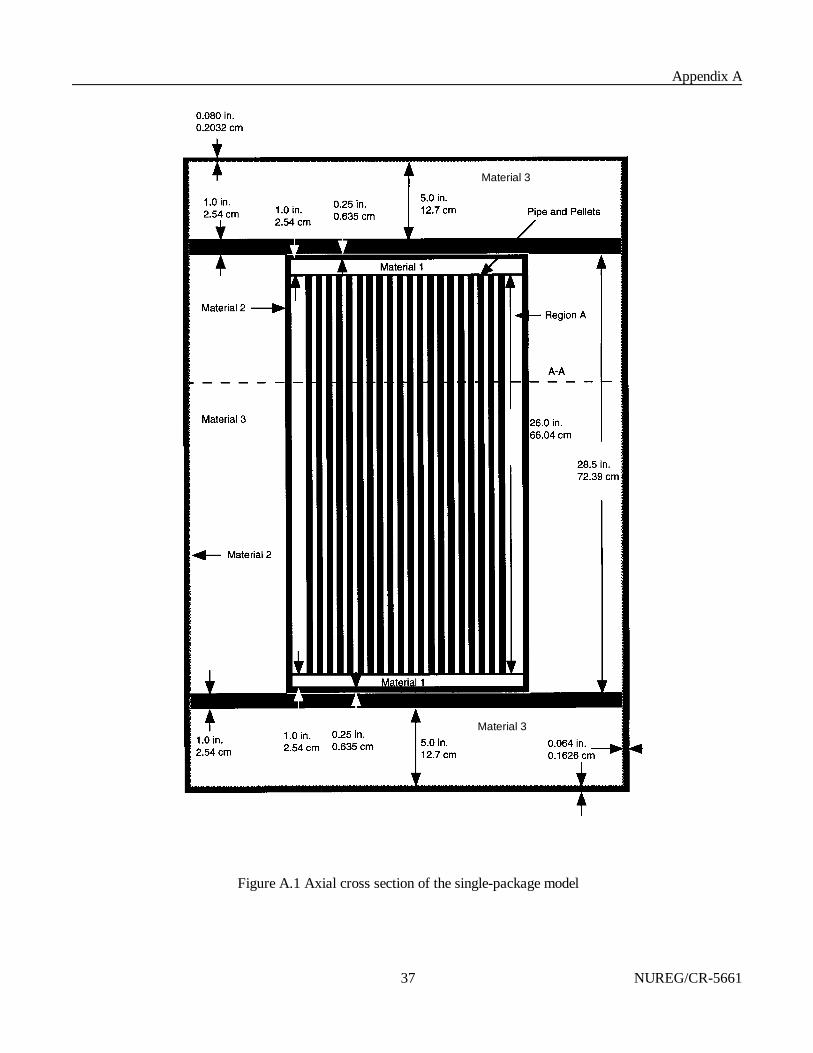
Appendix A
NUREG/CR-566137
Material 3
Material 3
Figure A.1 Axial cross section of the single-package model

Appendix A
NUREG/CR-5661 38
Figure A.2 Radial cross section of single-package model

Appendix A
NUREG/CR-566139
Table A.3 Material specifications for Figs. A.1 and A.2
Material No. Material Density (g/cm3) Model mass (kg) Actual mass (kg)
0 UO2 10.40 116.19 116.16
1 SS-304 7.92 a 41.87 42.12
2 Carbon steel 7.8212 a 73.37 77.23
3 Insulatingfiber board
0.24 46.42 44.29
4 Plywood 0.45 5.860 8.796
aSCALE Standard Composition Library values.
A.3.1.3 Models&Actual Package Differences
The single-package calculational model of the 55-gal drum differs from the actual drum in the treatment of thedrum wall. In the model, the drum wall is a straight wall cylinder without the rolling hoops. The drum modeldoes not have the top and bottom inset into the drum wall, bolts, locking rings, etc.
The rubber o-ring fittings around the tubes in the top plate of the inner container assembly were treated asstainless steel, the surrounding material. The change constitutes such a small change in stainless steel mass inthe positive axial direction relative to the fuel region that the impact on keff would be negligible. To simplifythe modeling, the center plywood support ring was modeled as insulating fiber board, the surroundingmaterial. The exchange of materials would have a negligible effect on keff because the constituents of the twomaterials are identical and the thickness of the region is small relative to the radial surface of the containmentvessel (i.e., -4% of the surface available for radial neutron leakage).
A.3.2 CONTENTS MODEL
Figure A.2 shows the package contents (pellets in tubes) configured for both the single-package and package-array calculations. Each tube is physically restricted to a maximum loading of 80 pellets. Partial-loading(variable-mass) configurations are allowed, as are variations in pellet enrichment (up to 4.01 wt % 235U).However, partial loadings must be from the inner tubes outward with only the last loaded tube containing lessthan 80 pellets (see Chapter 1). Because of this restriction and the fixed tube spacing, partial loadings do notrequire further analysis because they are bounded by the more reactive configuration of full loading. Chapter 2of the application for approval has shown that the tube spacing remains at 1.34 cm (0.528 in.), and that thepellets remain inside the tubes, under normal conditions of transport and hypothetical accident conditions.
A.3.3 SINGLE PACKAGES
To meet the general requirements for fissile material packages, 10 CFR § 71.55, a package must be designedand its contents so limited that it would be subcritical under the most reactive configuration of the material,optimum moderation, and close reflection of the containment system by water on all sides or surroundingmaterials of the packaging. Models of both reflective conditions have been considered. The package wassubjected to the tests specified in 10 CFR § 71.71, Normal Conditions of Transport, and, as reported in

Appendix A
NUREG/CR-5661 40
Dt '3(m/6)
12
dt3
2× dt h
'
m
d 2t ( 3/2) (h)
,
Ds '4(m/4)
d 2s (h)
'
m
d 2s (h)
,
Chapters 2 and 3, the geometric form of the package was not substantially altered, no water leakage into thecontainment occurred, and no substantial reduction in the effectiveness of the packaging was observed. Inshort, the damage incurred will not affect the technical evaluation, and the package contents under normalconditions of transport will be less reactive than the contents under the aforementioned general requirements,requiring no further analysis.
To address the requirement of 10 CFR § 71.55(e), a single package was analyzed with optimum internalmoderation and a 30-cm water reflector on all sides. The damaged package experienced a 4.7% reduction indiameter due to impact testing (see Chapter 2, Structural Evaluation). The packaging diameter reduction is tobe analyzed as a reduction in insulating fiber board and plywood thicknesses while conserving the carbon steeldrum, insulating fiber board, and plywood masses. Limited material loss occurred as a result of fire testing(see Chapter 3, Thermal Evaluation). The outer 0.8 in. (2.03 cm) of insulating fiber board (axially andradially) and plywood (radially) exhibited charring and off-gassing during the fire test. The regions weremodeled as residual carbon and water (immersion test). The water from the immersion test optimally moderatesthe inner containment. The minimal damage resulting from crush and puncture tests (see Chapter 2, StructuralEvaluation) will not influence the reactivity of the packages.
A.3.4 PACKAGE ARRAYS
Cylindrical transport packages such as this example package may be shipped in a tightly packed triangular-pitch configuration (or may be shifted to that configuration because of hypothetical accident conditions). Thisarrangement may provide a more reactive configuration than a square-pitch arrangement because the triangularpitch provides absolute minimum center-to-center spacing of the fissile contents, the maximum density offissile units, and thus the greatest potential for increased neutron interaction between fissile contents. To avoidthe complex modeling required to analyze triangular-pitch arrays with the computational method used in thisapplication, a square-pitch array model with a modified single-package model was developed to emulate theeffects of a triangular-pitch package array. The single-package modification involved a reduction of the drumdiameter by 7% to produce an array density in a square-pitch lattice equal to the array density of a triangular-pitch lattice of packages with the full-diameter package. If the mass of steel of the drum and the mass of theinsulating fiber board are conserved, the neutron reaction rates within the array are essentially identical. Toconserve the mass of steel in this example, the drum wall density was increased; and to conserve the mass ofthe insulating fiber board in this example, the insulating fiber board density was increased. The diameterreduction was applied only to regions of the "array package model," not the "contents model."
The justification for the 7% diameter reduction is seen in the following derivation. Consider three full-diameter packages in contact on triangular pitch and four reduced-diameter packages in contact on square pitch. The equivalent array density of each configuration is
and

Appendix A
NUREG/CR-566141
wherethe subscripts t and s indicate triangular and square pitch, respectively,d is the package diameter,h is the package height (same for both packages), andm is the fissile material mass (same for both packages).
If Dt is set equal to Ds and ds is calculated in terms of dt , the diameter of a square pitch is 0.9306 that of thetriangular pitch, to produce the equivalent array density. If a constant mass of materials is maintained outsidethe fissile unit (i.e., the thermal insulation and steel outer drum), the neutron reaction rates between fissileunits remain constant. Because the drum is smaller in diameter, the mass of thermal insulation is conserved byincreasing the density, and the mass of steel in the outer drum is conserved by increasing the steel density. Two array model types are included in the evaluation. The first model type consists of an infinite array ofclose-packed, triangular-pitch, undamaged packages consistent with the normal conditions of transport. From10 CFR § 71.59, standards for arrays of fissile material packages, undamaged package arrays are evaluatedwith void between the packages. The second model type consists of various size finite arrays of close-packedtriangular-pitch, damaged packages. As required by 10 CFR § 71.59, the damaged packages are evaluated as ifeach package was subjected to the tests specified in 10 CFR § 71.73, Hypothetical Accident Conditions, withoptimum interspersed hydrogenous moderation. Further, the finite array of packages must be reflected by 30 cmof water on all sides.
Various finite array sizes had to be investigated in order to ascertain the number of subcritical packages underhypothetical accident conditions. The condition of each damaged package in the array is that described inSect. A.3.3 for the single package.
A.4 METHOD OF ANALYSIS
Sections A.4.1 and A.4.2 describe the sequences and modules of the SCALE-4.3 system used in the analysis ofthese computational models. Section A.4.3 identifies all major code input parameters. Section A.4.4 discussesthe adequacy of the calculations.
All calculations were performed on CA02 and CA29, IBM RS/6000 workstations in the Computational Physicsand Engineering Division at ORNL with SCALE version 4.3 (1/6/97 production date) and the 44-groupENDF/B-V cross-section library.
A.4.1 COMPUTER CODE SYSTEM
SCALE is a computational system consisting of a set of well-established codes and data libraries suitable foranalyses of nuclear fuel facility and package designs in the areas of criticality safety, radiation shielding,source-term characterization, and heat transfer. The codes are compiled in a modular fashion and are called bycontrol modules that provide automated sequences for standard system analyses in each area. The CSAScontrol module contains automated sequences that perform problem-dependent cross-section processing andthree-dimensional (3-D) Monte Carlo calculations of neutron multiplication.
KENO V.a, a 3-D multigroup Monte Carlo criticality code, determines the effective multiplication factor (keff)from the problem-dependent cross-section data and the user-specified geometry data. Other calculated

Appendix A
NUREG/CR-5661 42
KENO V.a quantities include average neutron lifetime and generation time, energy-dependent leakages, energy-and region-dependent absorptions, fissions, fluxes, and fission densities.
A.4.2 CROSS SECTIONS AND CROSS-SECTION PROCESSING
All neutronic control sequences use the SCALE Material Information Processor to calculate material numberdensities, prepare geometry data for resonance self-shielding and optional flux-weighting cell calculations, andcreate data input files for the cross-section processing codes. The BONAMI and NITAWL-II codes are thenused to perform problem-specific (resonance- and temperature-corrected) cross-section processing. BONAMIapplies the Bondarenko method of resonance self-shielding for nuclides that have Bondarenko data included inthe cross-section library. NITAWL-II uses the Nordheim integral treatment to perform resonance self-shielding corrections for nuclides that have resonance parameters included with their cross-section data.
The analyses discussed in this evaluation were performed using the broad-structure, 44-group neutron cross-section library. The 44-group library was chosen because the evaluated package contents have manysimilarities (e.g., form, enrichment) to light-water-reactor (LWR) fuel, and the 44-group library hasdemonstrated markedly improved performance in LWR-type fuel analyses over the ENDF/B-IV 27-grouplibrary. The reason: the 44-group neutron cross-section library was collapsed from the 238-group AMPXmaster-format neutron cross-section library contains data for all the nuclides available in ENDF/B-V, and the44-group library was collapsed using a fuel cell spectrum based on a 17 × 17 Westinghouse pressurized-water-reactor (PWR) fuel assembly.
Additionally, the broad-group structure was designed to accommodate two windows in the oxygen cross-section spectrum, a window in the iron cross-section spectrum, the Maxwellian peak in the thermal range, andthe 0.3-eV resonance in 239Pu (which, because of low energy and lack of resonance data, cannot be modeled bythe Nordheim integral treatment in NITAWL-II).
A.4.3 CODE INPUT
All problems were started with a flat initial neutron distribution over the system, in fissile material only. Allproblems were run for 305 generations of 400 neutrons per generation, skipping the first five generations, fora total of 120,000 histories. Mirror image reflection was applied to the orthogonal-plane boundaries of thesingle-package model to simulate infinite array-package models. A 12-in. (30.48-cm) water differential albedowith four incident angles was applied to the outer boundary of the single-package models and finite-arraymodels to simulate tight, full-density water reflection. Biasing options were not applied.
Figures A.3(a) and A.3(b) are sample input files. The files correspond to cases f-2_4 and f-2_4a, a 4 × 4 × 1array of optimally moderated, damaged packages in square, with diameter correction factor of Sect. A.3.4, andtriangular-pitch arrays.
A.4.4 CONVERGENCE OF CALCULATIONS
UO2 mass data for each problem were checked against KENO V.a output. The input geometries were checkedby examining the 2-D plots generated by KENO V.a. Problem convergence was determined by examining plots of keff by generation run and skipped, as well as the final keff edit tables. No trends were observed eitherin keff by generation run over the last half of total generations or, correspondingly, in keff by generation skippedover the first half of total generations. No sudden changes of greater than one standard deviation in keff by

Appendix A
NUREG/CR-566143
=csas25KENO-V.a, 4x4x1 array, optimally moderated damaged’packages, square pitch, 4.7% and 7% diameter reduction44g lattuo2 1 0.9489 293 92235 4.01 92234 0.02 92236 0.02 92238 95.95 endh2o 2 1.0 endss304 3 1.0 endc 4 0 3.9250e-3 endfe 4 0 8.3498e-2 endh 5 0 1.293e-2 endc 5 0 7.757e-3 endo 5 0 6.464e-3 endh 6 0 2.128e-2 endc 6 0 1.277e-2 endo 6 0 1.064e-2 endc 7 0 4.550e-3 endfe 7 0 9.679e-2 endh 8 0 1.135e-2 endc 8 0 6.809e-3 endo 8 0 5.674e-3 endc 9 0 7.757e-3 endh2o 9 0.001 endc 10 0 6.809e-3 endh2o 10 0.001 endh2o 12 1.0 endend compsquarepitch 1.34 0.8255 1 2 0.9296 3 0.889 12 endread parm run=yes plt=no gen=305 npg=400 nsk=5 end parmread geomunit 1cylinder 1 1 0.4128 2p33.02cylinder 2 1 0.4445 2p33.02cylinder 3 1 0.4648 2p33.02cuboid 2 1 4p0.670 2p33.02unit 2cylinder 3 1 0.667 2p33.02cuboid 2 1 4p0.670 2p33.02unit 3array 2 -4.02 0 -33.02unit 4array 3 -6.7 0 -33.02unit 5array 4 0 -4.02 -33.02unit 6array 5 0 -6.7 -33.02unit 7array 1 -10.72 -10.72 -33.02cylinder 2 1 15.24 2p33.02hole 6 10.72 0 0hole 6 -12.06 0 0hole 5 12.06 0 0hole 5 -13.41 0 0hole 4 0 10.72 0hole 4 0 -12.06 0hole 3 0 12.06 0hole 3 0 -13.41 0reflector 3 1 0 2r2.54 1reflector 4 1 3r0.635 1reflector 5 1 7.4165 2r0 1reflector 9 1 2.032 2r0 1reflector 6 1 0 2r2.54 1reflector 8 1 0 2r10.668 1reflector 10 1 0 2r2.032 1reflector 7 1 0.1626 0.2032 0.1626 1cuboid 0 1 4p25.4862 51.6383 -51.5977global unit 8array 6 3*0.0end geomread arrayara=1 nux=16 nuy=16 nuz=1 fill 2 14r1 2 224r1 2 14r1 2end fillara=2 nux=6 nuy=1 nuz=1 fill 6r1 end fillara=3 nux=10 nuy=1 nuz=1 fill 10r1 end fillara=4 nux=1 nuy=6 nuz=1 fill 6r1 end fillara=5 nux=1 nuy=10 nuz=1 fill 10r1 end fillara=6 nux=4 nuy=4 nuz=1 fill 16r7 end fillend arrayread bnds all=h2o end bndsend dataend
Figure A.3a Sample input file f-2_4
=csas26KENO-VI, 4x4x1 array, optimally moderated damaged’packages, triangular pitch, 4.7% diam. reduction44g lattuo2 1 0.9489 293 92235 4.01 92234 0.02 92236 0.02 9223895.95 endh2o 2 1.0 endss304 3 1.0 endc 4 0 3.9250e-3 endfe 4 0 8.3498e-2 endh 5 0 1.029e-2 endc 5 0 6.173e-3 endo 5 0 5.144e-3 endh 6 0 1.841e-2 endc 6 0 1.105e-2 endo 6 0 9.207e-3 endc 7 0 4.167e-3 endfe 7 0 8.864e-2 endh 8 0 9.821e-3 endc 8 0 5.892e-3 endo 8 0 4.910e-3 endc 9 0 6.173e-3 endh2o 9 0.001 endc 10 0 5.892e-3 endh2o 10 0.001 endh2o 11 1.0 endend compsquarepitch 1.34 0.8255 1 2 0.9296 3 0.889 11 endread parm run=yes plt=no gen=305 npg=400 nsk=5 end parmread geomunit 1cylinder 10 0.4128 2p33.02cylinder 20 0.4445 2p33.02cylinder 30 0.4648 2p33.02cuboid 40 4p0.670 2p33.02media 1 1 10media 2 1 20 -10media 3 1 30 -20 -10media 2 1 40 -30 -20 -10boundary 40unit 2cylinder 10 0.667 2p33.02cuboid 20 4p0.670 2p33.02media 3 1 10media 2 1 20 -10boundary 20unit 3cuboid 10 4p0.670 2p33.02media 2 1 10boundary 10unit 4cylinder 10 15.24 2p33.02array 1 10 place 12 12 1 -0.67 -0.67 0cylinder 20 15.24 2p35.56cylinder 30 15.875 2p36.195cylinder 40 25.1922 2p36.195cylinder 50 27.2242 2p36.195cylinder 60 27.2242 2p38.735cylinder 70 27.2242 2p49.403cylinder 80 27.2242 2p51.435cylinder 90 27.3868 51.6382 -51.5976hexprism 100 27.3869 51.6383 -51.5977media 3 1 20 -10media 4 1 30 -20media 5 1 40 -30media 9 1 50 -40media 6 1 60 -50media 8 1 70 -60media 10 1 80 -70media 7 1 90 -80media 0 1 100 -90boundary 100unit 5hexprism 10 27.3869 51.6383 -51.5977media 2 1 10boundary 10global unit 6cylinder 10 189.74 51.6383 -51.5977array 2 10 place 5 5 1 -27.3869 -27.3869 0cylinder 20 225. 2p82.media 2 1 20 -10boundary 20end geomread arrayara=1 nux=24 nuy=24 nuz=1 fill 48r3 9r3 6r1 9r3 7r3 10r17r3 4r3 2 14r1 2 4r3 4r3 16r1 4r3 1q24 3r3 18r1 3r3 1q242r3 20r1 2r3 5q24 3r3 18r1 3r3 1q24 4r3 16r1 4r3 1q244r3 2 14r1 2 4r3 7r3 10r1 7r3 9r3 6r1 9r3 48r3 end fillara=2 typ=tri nux=10 nuy=10 nuz=1 fill 30r5 4r5 4r4 2r53r5 4r4 3r5 3r5 4r4 3r5 2r5 4r4 4r5 30r5 end fillend arrayend dataend
Figure A.3b Sample input file f-2_4a

Appendix A
NUREG/CR-5661 44
generation run or skipped, resulting from an abnormal keff generation, were found. Frequency distribution bargraphs appear to approximate normal distribution with single peaks and no significant outlying values.
A.5 VALIDATION OF CALCULATION METHOD
For the purpose of this example, a negative value of 0.01 will be assumed for the bias and uncertainty associated with using SCALE-4.3 and the 44-group cross-section library. This is consistent with()ku & $̄)
published information on validation of this computational method using low-enriched lattice criticals.10,12 Note:The applicant should demonstrate the justification for the bias and uncertainty in the application for approval.
Using the general equation for the USL from Sect. 5.4 and the requirements of 10 CFR 71, it can be foundthat for the calculations to be considered subcritical, the following condition should be satisfied:
keff + 2F # 0.95 % )ku + ,$̄
keff + 2F # 0.94 .
A.6 CRITICALITY CALCULATIONS AND RESULTS
This evaluation demonstrates the subcriticality of a single package (Sect. A.6.1) and an array of packages(Sect. A.6.2) during normal conditions of transport and hypothetical accident conditions. The determined TIfor criticality control of a damaged and undamaged shipment is given in Sect. A.6.3.
A.6.1 SINGLE PACKAGE
Calculations show that a single package remains subcritical under general requirements for fissile materialpackages under normal conditions of transport and under hypothetical accident conditions. To meet the generalrequirements for fissile material packages, 10 CFR § 71.55, a package must be designed and its contents solimited that it would be subcritical under the most reactive configuration of the material, optimum moderation,and close reflection of the containment system by water on all sides or surrounding materials of the packaging.Case s-0 of Table A.4 represents the optimally moderated inner containment reflected on all sides by 30 cm ofwater. For case s-1, the container reflection is provided by the surrounding materials of the packaging and30 cm of water. In both cases, the gap region between the tubes and pellets are completely flooded with full-density water, as is the void region in the inner container (Region A of Fig. A.2). Full-density water isoptimum in both regions because the fissile content of the package is slightly undermoderated at a tube pitch of1.34 cm (see Fig. A.4). The highest single-package keff of 0.8942 ± 0.0019 is considered subcritical (i.e.,0.8942 + 2 @ 0.0019 = 0.8980 < 0.94).
Case s-2 in Table A.4 is the result for a single damaged package with internal water flooding and 30 cm ofwater reflection on all sides. As with the undamaged cases, the reported keff is less than the established USL of0.94. The results for a reflected, damaged containment system would have been identical to the undamagedcase (case s-0) because the configurations of the containment system or contents did not change underhypothetical accident conditions.
All calculations (damaged and undamaged) were performed at the maximum allowable 235U enrichment(4.01 wt %) to ensure maximum reactivity and eliminate the need for calculations at lower possible enrichments.

Appendix A
NUREG/CR-566145
1.32
1.33
1.34
1.35
1.36
k-in
f
1.25 1.3 1.35 1.4 1.45 1.5 pitch (cm)
Table A.4 Single-package calculations
Case Description keff ± F
s-0 Optimally moderated, reflected undamaged containment 0.8942 ± 0.0019
s-1 Optimally moderated, reflected undamaged package 0.8798 ± 0.0019
s-2 Optimally moderated, reflected damaged package 0.8820 ± 0.0018
Figure A.4 k4
vs pitch for 4.01 wt % 235U UO2 pellets
A.6.2 PACKAGE ARRAYS
The calculational results of Table A.5 show that an infinite array of packages is adequately subcritical undernormal conditions of transport. Case i-1, an infinite, triangular-pitch array of dry packages under normalconditions, calculates at a keff of 0.5343 ± 0.0012. An infinite array of packages under hypothetical accidentconditions, however, is not subcritical. Case i-2_7 represents an infinite array of close-packed, triangular-pitch(diameter reduction factor), flooded packages with optimum moderated contents, a 4.7% reduction in diameter,effects due to charring and off-gassing, and optimum interspersed moderation. The keff for case i-2_7 is 0.9755± 0.0021, which exceeds the subcritical limit (i.e., 0.9755 + [email protected] = 0.9797 > 0.94). Since the infinitearray under hypothetical accident conditions calculates above the USL, finite array calculations are necessary.
Cases i-3_1 through i-3_3 are variants of i-2_7 that investigate flooding of the insulating fiber board charredregion. The optimally moderated package array i-3_2 has full-density water inside the package containment,has 0.001 g H2O/cm3 in the charred region of the packaging, and has void between packages.

Appendix A
NUREG/CR-5661 46
Table A.5 Results for triangular-pitch array calculations
Case
InterspersedH2O density (g/cm3) Description keff ± F
i-1 0 Infinite array, normal conditions of transport 0.5343 ± 0.0012
f-1 % 1×1×1 array, hypothetical accident conditions 0.8820 ± 0.0018
i-2_1 0.9982 Infinite, hypothetical accident conditions 0.9238 ± 0.0021
i-2_2 0.95 Infinite, hypothetical accident conditions 0.9237 ± 0.0021
i-2_3 0.5 Infinite, hypothetical accident conditions 0.9297 ± 0.0023
i-2_4 0.1 Infinite, hypothetical accident conditions 0.9618 ± 0.0025
i-2_5 0.01 Infinite, hypothetical accident conditions 0.9716 ± 0.0024
i-2_6 0.001 Infinite, hypothetical accident conditions 0.9718 ± 0.0024
i-2_7 0a Infinite, hypothetical accident conditions 0.9755 ± 0.0021
i-3_1 0 Infinite, hypothetical accident conditions, 0 g H2O/cm3 charred region
0.9755 ± 0.0021
i-3_2 0 Infinite, hypothetical accident conditions, 0.01b H2O/cm3 charred region
0.9772 ± 0.0027
i-3_3 0 Infinite, hypothetical accident conditions, 0.01 g H2O/cm3 charred region
0.9759 ± 0.0022
f-2_1 0 2×2×1 array, hypothetical accident conditions 0.9103 ± 0.0018
f-2_2 0 2×2×2 array, hypothetical accident conditions 0.9158 ± 0.0018
f-2_3 0 3×3×1 array, hypothetical accident conditions 0.9270 ± 0.0017
f-2_4 0 4×4×1 array, hypothetical accident conditions 0.9369 ± 0.0019
f-2_4a 0 4×4×1 array, hypothetical accident conditions 0.9335 ± 0.0028c
f-2_5 0 3×3×2 array, hypothetical accident conditions 0.9306 ± 0.0017
f-2_6 0 5×5×1 array, hypothetical accident conditions 0.9284 ± 0.0019
f-2_7 0 3×3×3 array, hypothetical accident conditions 0.9405 ± 0.0023
f-2_8 0 4×4×2 array, hypothetical accident conditions 0.9359 ± 0.0017aDetermined to be near optimum interstitial moderation via CSAS4 search.bDetermined to be new optimum moderation via CSAS4 searchcKENO-VI calculation.

Appendix A
NUREG/CR-566147
Cases f-2_1 through f-2_8 are variants of case i-3_2 and represent finite arrays of close-packed, triangular-pitch packages (diameter reduction factor) that have optimally moderated contents, a reduced diameter by4.7%, charred insulating fiber board, varying interstitial moderation, and 30 cm of full-density water reflectiontightly fit on the array boundary. The finite array of 4 × 4 × 2 (case f-2_8) packages is considered justsubcritical because 0.9359 + [email protected] = 0.9393 falls below the USL of 0.94.
Case f-2_4a is equivalent to case f-2_4a except that f-2_4a was modeled with KENO-VI, which allows explicitmodeling of triangular-pitch arrays and does not require the use of the drum diameter reduction factor ofSect. A.3.4. The calculational results of f-2_4 and f-2_4a are statistically the same, attesting to the correctnessof the diameter reduction factor.
A.6.3 TRANSPORTATION INDEX
The TI for criticality control is determined by the number of packages that remain below the USL. For normalconditions of transport, an infinite array of packages is subcritical. However, under hypothetical accidentconditions, only up to 32 damaged packages would remain subcritical. Thus a maximum of 16 packages maybe shipped for a nonexclusive shipment, and the TI = 3.
Note: The example presented in this appendix is for illustrative purposes only. The fictitious transportpackage used in this example has not been approved by the NRC, and no assessment has been made as towhether the package would meet the requirements for NRC approval. Also, the descriptions, calculations, andjustifications presented in this example have not been fully reviewed by the NRC, and may not be complete oracceptable to the NRC.


NRC FORM 335 U.S. NUCLEAR REGULATORYCOMMISSION(2-89)NRCM 1102 BIBLIOGRAPHIC DATA SHEET3201, 3202 ( See instructions on the reverse)
1. REPORT NUMBER(Assigned by NRC, Add Vol., Supp.,Rev., and Addendum Numbers,
if any.)
NUREG/CR-5661 ORNL/TM-119362. TITLE AND SUBTITLE
Recommendations for Preparing the Criticality Safety Evaluation of TransportationPackages 3. DATE REPORT PUBLISHED
MONTH
AprilYEAR
1997
4. FIN OR GRANT NUMBER
B0009
5. AUTHOR(S)
H. R. Dyer, C. V. Parks
6. TYPE OF REPORT
Technical
7. PERIOD COVERED (Inclusive Dates)
8. PERFORMING ORGANIZATION — NAME AND ADDRESS (If NRC, provide Division, Office or Region, U.S. Nuclear Regulatory Commission, and mailing address;if contractor, provide name and mailing address.)
Oak Ridge National LaboratoryManaged by Lockheed Martin Energy Research CorporationOak Ridge, TN 37831-6370
9. SPONSORING ORGANIZATION — NAME AND ADDRESS (If NRC, type “Same as above”; if contractor, provide NRC Division, Office or Region, U.S. RegulatoryCommission, and mailing address.)
Spent Fuel Project OfficeOffice of Nuclear Material Safety and SafeguardsU.S. Nuclear Regulatory CommissionWashington, DC 20555-0001
10. SUPPLEMENTARY NOTES
M. G. Bailey, NRC Project Manager
11. ABSTRACT (200 words or less)
This report provides recommendations on preparing the criticality safety section of an application for approval of atransportation package containing fissile material. The analytical approach to the evaluation is emphasized rather thanthe performance standards that the package must meet. Where performance standards are addressed, this reportincorporates the requirements of 10 CFR Part 71.
12. KEY WORDS/DESCRIPTORS (List words or phrases that will assist researchers in locating the report.)
transportation, criticality safety, safety analysis, fissile material
13. AVAILABILITY STATEMENT
unlimited
14. SECURITY CLASSIFICATION
(This Page) unclassified
(This Report) unclassified
15. NUMBER OF PAGES
16. PRICE
��������15&�)250�����������