recommended tools gameboy color disassembly procedure · gameboy color case modification 1.place...
TRANSCRIPT

Game Boy Color Replacemnt LCD Module
DatasheetThe Game Boy Color Replacement module is a near drop in replacement
for the original LCD with many enhancements.
• Full Color TFT Transflective Backlight Screen (Daylight Visible)
• Integer scaled to 320 x 288
• PWM Brightness control by holding select and using up / down on dpad
• Air Duster
• Microfiber Cloth
• Isopropyl Alcohol
• #0 TriWing Screwdriver
• #1 Phillips Screwdriver
• Soldering Iron
Recommended Tools
GameBoy Color Disassembly Procedure1. Open the Game Boy Color by removing the four (4) brass screws using a #0 Triwing screwdriver.
2. Open the battery compartment and remove the batteries. Remove the two (2) brass screws from inside the battery compartment.
3. Remove the rear housing, taking care not to damage the battery contacts as they slide through the rear housing. As you lift up the rear housing the power slide switch may fall out. Remove the power slide switch. Set the rear housing and power slide switch aside.
4. Release both of the black tabs on the LCD ribbon connector (P2) by sliding them towards the top of the Game Boy Color.
5. Gently grip the ribbon cable on both sides between your thumb and index finger. Rock the ribbon cable slightly from side to side and pull gently towards the top of the Game Boy Color. The ribbon cable should gradually slide out. CAUTION: Be careful not to fold over the sides of the ribbon cable or fold it too tightly.
6. Remove the 3 philips screws holding the PCB to the front housing using a #1 Phillips screwdriver.
7. Lift the PCB out. CAUTION: Be careful of the speaker wires. The speaker may stick in the front housing. Set the PCB aside.
8. OPTIONAL: Now is an excellent time to clean up your PCB. Clean the speaker and the switch contact pads using some Isopropyl Alcohol (IPA) and cotton swabs. Wet the end of the swab and gently rub over the contacts. Repeat using new swabs until the swabs no longer look dirty after use.
• 3038 AWG Magnet wire or Wire Wrap Wire
• Flush Side Cutters
• Nibbler
• File
• Super glue

9. Remove the three (3) rubber pieces from the lower half of the front housing. Remove the D pad plastic piece, the A and B buttons and the IR window. Set these pieces aside.
10. To remove the LCD, grip the front case with your left hand on the top of the front case and your right hand just below the LCD. Twist the front housing slightly until the adhesive holding the screen releases. It should only be necessary to twist the front case by ¼” (<1cm). The adhesive will likely not let go around the screen all at once. Using a plastic spudger, gently separate the screen from any remaining adhesive. It is not important that the adhesive remains on the front case. Carefully lift the LCD out of the housing and set the LCD aside.
11. Looking at the front of the front housing, position your thumbs on the top of the front housing and, using your index fingers, press towards yourself on the front screen protector until the adhesive releases.CAUTION: A moderate amount of pressure is required to release the adhesive, so start with a low amount of pressure and increase until the adhesive releases. Work around the rest of the screen protector to release the remaining adhesive. Set the screen protector aside.
GameBoy Color Case Modification1. Place the new LCD module gently where the original lcd was and mark above and below the ribbon cable on the left side of the module.
2. Use a pair of side cutters to cut the marked locations down to the surface and pry on the plastic tab until it breaks off.
3. Print and Cut out the template then place on the front housing where the lenses would go.
4. Trace the inner section of the template with a marker so you know how much material needs to be removed.
5. Remove the marked material with your prefered method (Dremel, File, Nibbler)
6. Once the excess material is removed test fit the new LCD module and adjust fit as necessary.
7. Trimming to the left and right of the 50pin flat flex cable will allow more space for your mod wires and make instalation easier and reduce the likelyhood of damaging your mod wires.
8. To the left is a fully modified case ready for Instalation of a LCD Module.
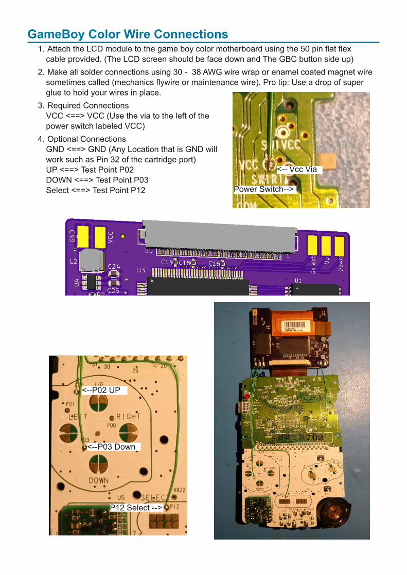
1. Attach the LCD module to the game boy color motherboard using the 50 pin flat flex cable provided. (The LCD screen should be face down and The GBC button side up)
2. Make all solder connections using 30 38 AWG wire wrap or enamel coated magnet wire sometimes called (mechanics flywire or maintenance wire). Pro tip: Use a drop of super glue to hold your wires in place.
3. Required Connections VCC <==> VCC (Use the via to the left of the power switch labeled VCC)
4. Optional Connections GND <==> GND (Any Location that is GND will work such as Pin 32 of the cartridge port) UP <==> Test Point P02 DOWN <==> Test Point P03 Select <==> Test Point P12
GameBoy Color Wire Connections
< Vcc Via
<P02 UP
<P03 Down
P12 Select >
Power Switch>

Alternative wire locations for clear casesNote: These alternative wire locations have solder mask on them so you will need to lightly scrape the solder mask off for the solder to adhear. This modification is more advanced as the solder points are smaller and more dificult to get a good solder joint due to the solder mask.
Select >
< Down
UP>
< Pad Location
