reconfigurable integrated circuits for reimagine - … v3.pdf · reconfigurable integrated circuits...
TRANSCRIPT

© (2016) MASSACHUSETTS INSTITUTE OF TECHNOLOGY
Subject to FAR 52.227-11 – Patent Rights – Ownership by the Contractor (May 2014)
Jonathan FrechetteAdvanced Imager Technology Group
MIT Lincoln Laboratory30 September 2016
Reconfigurable Integrated Circuits for ReImagine
This material is based upon work supported by the Defense Advanced Research Projects Agency (DARPA) under Air Force Contract No. FA8721-05-C-0002 and/or FA8702-15-D-0001. Any opinions, findings and conclusions or recommendations expressed in this material are those of the author(s) and do not necessarily reflect the views of the United States Government.
DISTRIBUTION STATEMENT A: Approved for public release: distribution unlimited.
Delivered to the U.S. Government with Unlimited Rights, as defined in DFARS Part 252.227-7013 or 7014 (Feb 2014). Notwithstanding any copyright notice, U.S. Government rights in this work are defined by DFARS 252.227-7013 or DFARS 252.227-7014 as detailed above. Use of this work other than as specifically authorized by the U.S. Government may violate any copyrights that exist in this work.
© (2016) MASSACHUSETTS INSTITUTE OF TECHNOLOGYSubject to FAR 52.227-11 – Patent Rights – Ownership by the Contractor (May 2014)
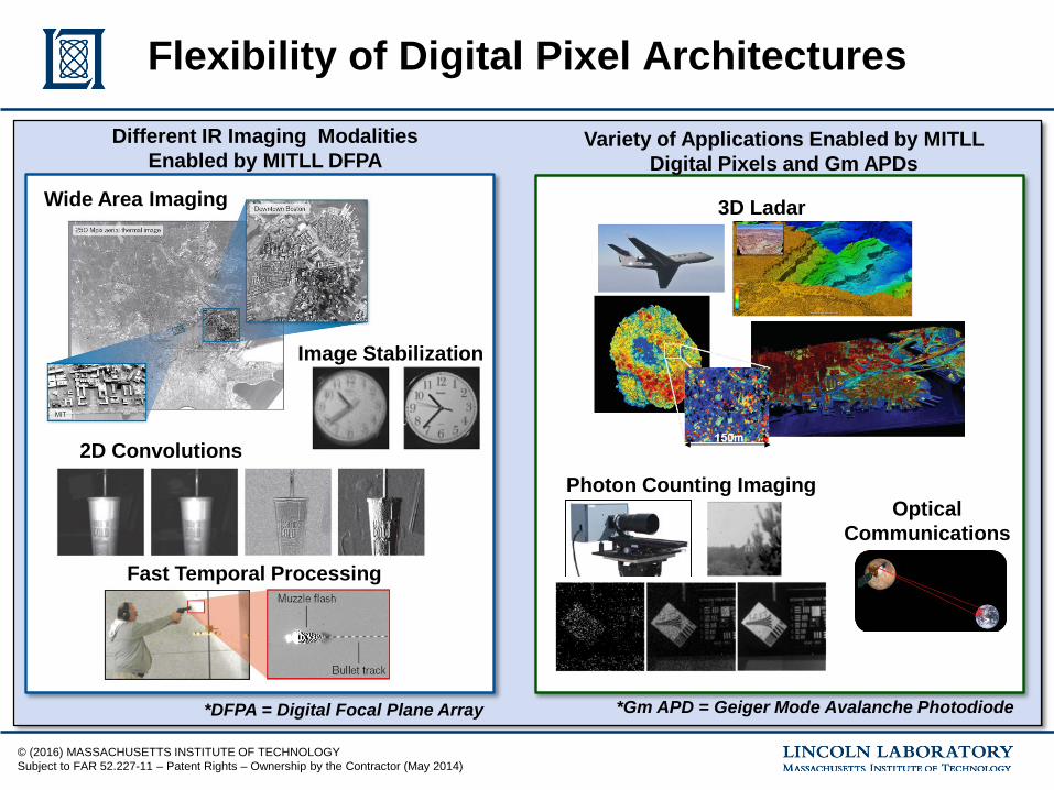
Flexibility of Digital Pixel ArchitecturesDifferent IR Imaging Modalities
Enabled by MITLL DFPAVariety of Applications Enabled by MITLL
Digital Pixels and Gm APDs
3D Ladar
Photon Counting ImagingOptical
Communications
Wide Area Imaging
2D Convolutions
Fast Temporal Processing
Image Stabilization
*DFPA = Digital Focal Plane Array *Gm APD = Geiger Mode Avalanche Photodiode
© (2016) MASSACHUSETTS INSTITUTE OF TECHNOLOGYSubject to FAR 52.227-11 – Patent Rights – Ownership by the Contractor (May 2014)
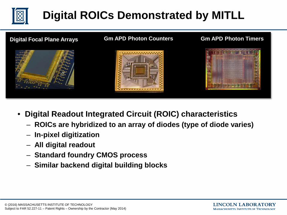
Digital ROICs Demonstrated by MITLL
• Digital Readout Integrated Circuit (ROIC) characteristics– ROICs are hybridized to an array of diodes (type of diode varies)– In-pixel digitization– All digital readout– Standard foundry CMOS process– Similar backend digital building blocks
Digital Focal Plane Arrays Gm APD Photon Counters Gm APD Photon TimersDigital Focal Plane Arrays Gm APD Photon Counters Gm APD Photon Timers
© (2016) MASSACHUSETTS INSTITUTE OF TECHNOLOGYSubject to FAR 52.227-11 – Patent Rights – Ownership by the Contractor (May 2014)
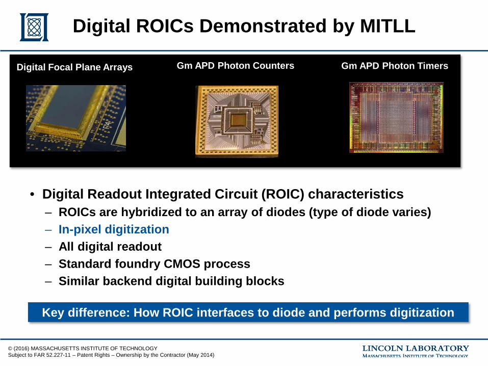
Digital ROICs Demonstrated by MITLL
• Digital Readout Integrated Circuit (ROIC) characteristics– ROICs are hybridized to an array of diodes (type of diode varies)– In-pixel digitization– All digital readout– Standard foundry CMOS process– Similar backend digital building blocks
Key difference: How ROIC interfaces to diode and performs digitization
Digital Focal Plane Arrays Gm APD Photon Counters Gm APD Photon TimersDigital Focal Plane Arrays Gm APD Photon Counters Gm APD Photon Timers
© (2016) MASSACHUSETTS INSTITUTE OF TECHNOLOGYSubject to FAR 52.227-11 – Patent Rights – Ownership by the Contractor (May 2014)
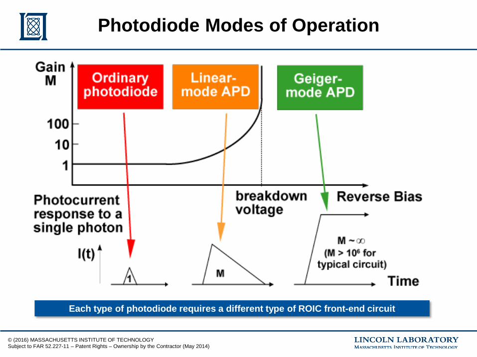
Photodiode Modes of Operation
Each type of photodiode requires a different type of ROIC front-end circuit
© (2016) MASSACHUSETTS INSTITUTE OF TECHNOLOGYSubject to FAR 52.227-11 – Patent Rights – Ownership by the Contractor (May 2014)
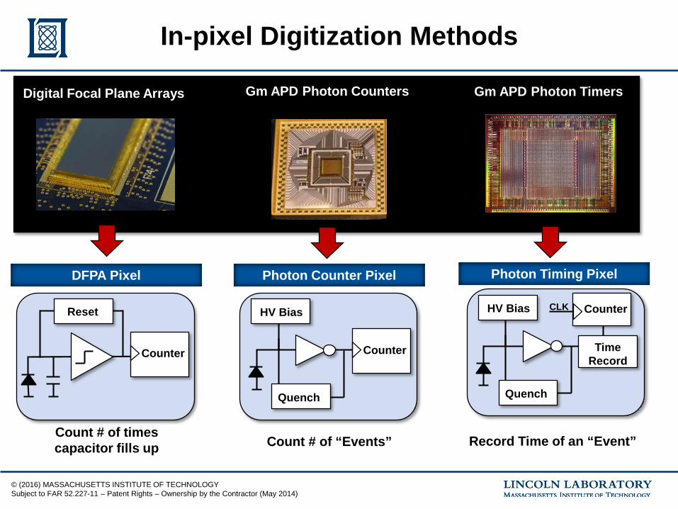
In-pixel Digitization Methods
DFPA Pixel Photon Counter Pixel Photon Timing Pixel
Counter
Reset
Counter
HV Bias
Quench
HV Bias
Quench
CLK Counter
TimeRecord
Count # of times capacitor fills up Count # of “Events” Record Time of an “Event”
Digital Focal Plane Arrays Gm APD Photon Counters Gm APD Photon TimersDigital Focal Plane Arrays Gm APD Photon Counters Gm APD Photon Timers
© (2016) MASSACHUSETTS INSTITUTE OF TECHNOLOGYSubject to FAR 52.227-11 – Patent Rights – Ownership by the Contractor (May 2014)
Digital Focal Plane Arrays Gm APD Photon Counters Gm APD Photon TimersDigital Focal Plane Arrays Gm APD Photon Counters Gm APD Photon Timers
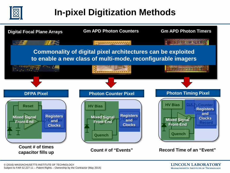
In-pixel Digitization Methods
DFPA Pixel Photon Counter Pixel Photon Timing Pixel
Counter
Reset
Counter
HV Bias
Quench
HV Bias
Quench
CLK Counter
TimeRecord
Count # of times capacitor fills up Count # of “Events” Record Time of an “Event”
Mixed Signal Front-End
Mixed Signal Front-End Mixed Signal
Front-End
Registersand
Clocks
Registersand
Clocks
Registersand
Clocks
Commonality of digital pixel architectures can be exploitedto enable a new class of multi-mode, reconfigurable imagers
© (2016) MASSACHUSETTS INSTITUTE OF TECHNOLOGYSubject to FAR 52.227-11 – Patent Rights – Ownership by the Contractor (May 2014)
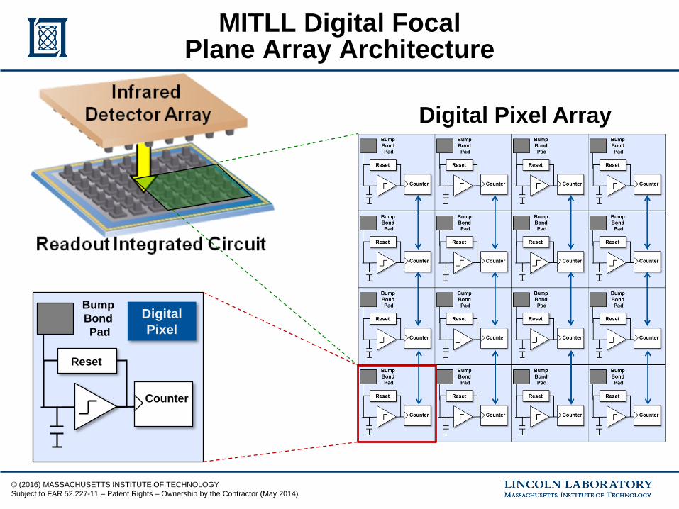
MITLL Digital Focal Plane Array Architecture
Reset
Counter
Bump BondPad
Digital Pixel
Digital Pixel Array
© (2016) MASSACHUSETTS INSTITUTE OF TECHNOLOGYSubject to FAR 52.227-11 – Patent Rights – Ownership by the Contractor (May 2014)
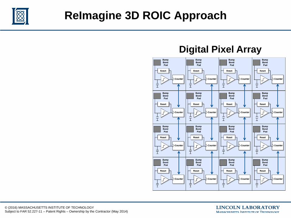
ReImagine 3D ROIC Approach
Digital Pixel Array
© (2016) MASSACHUSETTS INSTITUTE OF TECHNOLOGYSubject to FAR 52.227-11 – Patent Rights – Ownership by the Contractor (May 2014)
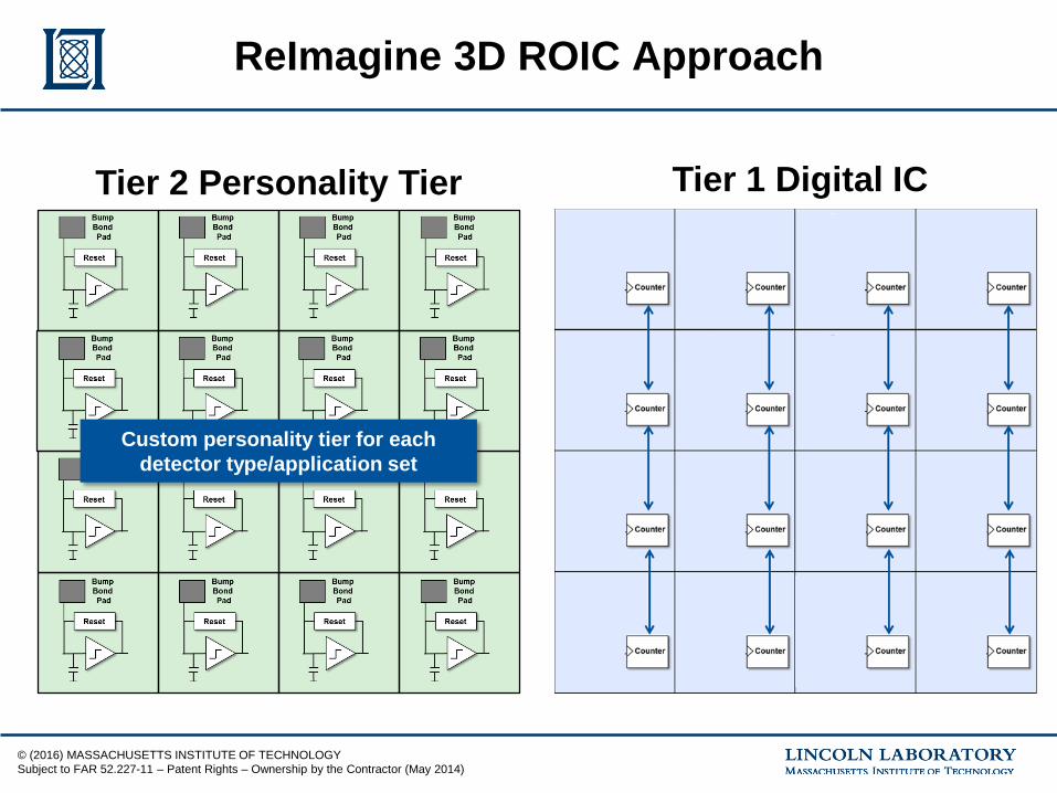
ReImagine 3D ROIC Approach
Tier 1 Digital ICTier 2 Personality Tier
Custom personality tier for each detector type/application set
© (2016) MASSACHUSETTS INSTITUTE OF TECHNOLOGYSubject to FAR 52.227-11 – Patent Rights – Ownership by the Contractor (May 2014)
ReImagine 3D ROIC Approach
Tier 1 Digital IC
Config Bits Config Bits Config Bits Config Bits
Config Bits Config Bits ConfigBits Config Bits
Config Bits Config Bits Config Bits Config Bits
ConfigBits Config Bits Config Bits Config Bits
Flex
ible
Rou
ting
Flex
ible
Rou
ting
Flex
ible
Rou
ting
Flex
ible
Rou
ting
Flex
ible
Rou
ting
Flex
ible
Rou
ting
Flex
ible
Rou
ting
Flex
ible
Rou
ting
Flex
ible
Rou
ting
Flex
ible
Rou
ting
Flex
ible
Rou
ting
Flex
ible
Rou
ting
Flex
ible
Rou
ting
Flex
ible
Rou
ting
Flex
ible
Rou
ting
Flex
ible
Rou
ting
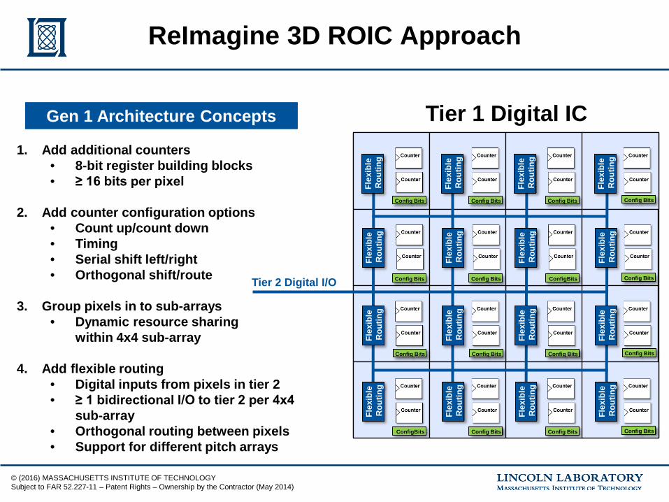
1. Add additional counters• 8-bit register building blocks• ≥ 16 bits per pixel
2. Add counter configuration options• Count up/count down• Timing• Serial shift left/right• Orthogonal shift/route
3. Group pixels in to sub-arrays• Dynamic resource sharing
within 4x4 sub-array
4. Add flexible routing• Digital inputs from pixels in tier 2• ≥ 1 bidirectional I/O to tier 2 per 4x4
sub-array• Orthogonal routing between pixels• Support for different pitch arrays
Gen 1 Architecture Concepts
Tier 2 Digital I/O
© (2016) MASSACHUSETTS INSTITUTE OF TECHNOLOGYSubject to FAR 52.227-11 – Patent Rights – Ownership by the Contractor (May 2014)
ReImagine 3D ROIC Approach
Tier 1 Digital IC
Config Bits Config Bits Config Bits Config Bits
Config Bits Config Bits ConfigBits Config Bits
Config Bits Config Bits Config Bits Config Bits
ConfigBits Config Bits Config Bits Config Bits
Flex
ible
Rou
ting
Flex
ible
Rou
ting
Flex
ible
Rou
ting
Flex
ible
Rou
ting
Flex
ible
Rou
ting
Flex
ible
Rou
ting
Flex
ible
Rou
ting
Flex
ible
Rou
ting
Flex
ible
Rou
ting
Flex
ible
Rou
ting
Flex
ible
Rou
ting
Flex
ible
Rou
ting
Flex
ible
Rou
ting
Flex
ible
Rou
ting
Flex
ible
Rou
ting
Flex
ible
Rou
ting
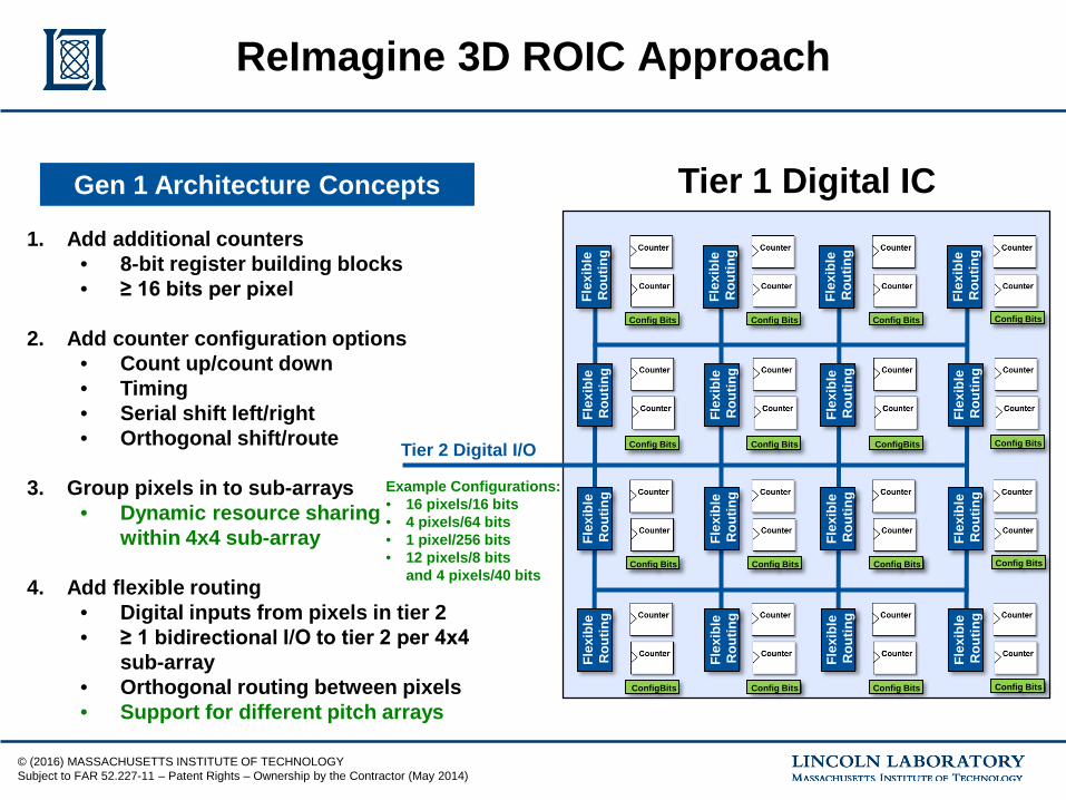
1. Add additional counters• 8-bit register building blocks• ≥ 16 bits per pixel
2. Add counter configuration options• Count up/count down• Timing• Serial shift left/right• Orthogonal shift/route
3. Group pixels in to sub-arrays• Dynamic resource sharing
within 4x4 sub-array
4. Add flexible routing• Digital inputs from pixels in tier 2• ≥ 1 bidirectional I/O to tier 2 per 4x4
sub-array• Orthogonal routing between pixels• Support for different pitch arrays
Gen 1 Architecture Concepts
Tier 2 Digital I/O
Example Configurations:• 16 pixels/16 bits• 4 pixels/64 bits• 1 pixel/256 bits• 12 pixels/8 bits
and 4 pixels/40 bits
© (2016) MASSACHUSETTS INSTITUTE OF TECHNOLOGYSubject to FAR 52.227-11 – Patent Rights – Ownership by the Contractor (May 2014)
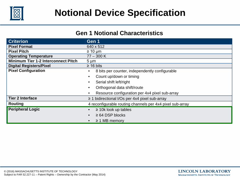
Notional Device Specification
Criterion Gen 1Pixel Format 640 x 512Pixel Pitch ≥ 10 µmOperating Temperature 77 – 300 KMinimum Tier 1-2 Interconnect Pitch 5 µmDigital Registers/Pixel ≥ 16 bitsPixel Configuration • 8 bits per counter, independently configurable
• Count up/down or timing• Serial shift left/right• Orthogonal data shift/route• Resource configuration per 4x4 pixel sub-array
Tier 2 Interface ≥ 1 bidirectional I/Os per 4x4 pixel sub-arrayRouting 4 reconfigurable routing channels per 4x4 pixel sub-arrayPeripheral Logic • ≥ 10k look up tables
• ≥ 64 DSP blocks• ≥ 1 MB memory
Gen 1 Notional Characteristics
© (2016) MASSACHUSETTS INSTITUTE OF TECHNOLOGYSubject to FAR 52.227-11 – Patent Rights – Ownership by the Contractor (May 2014)
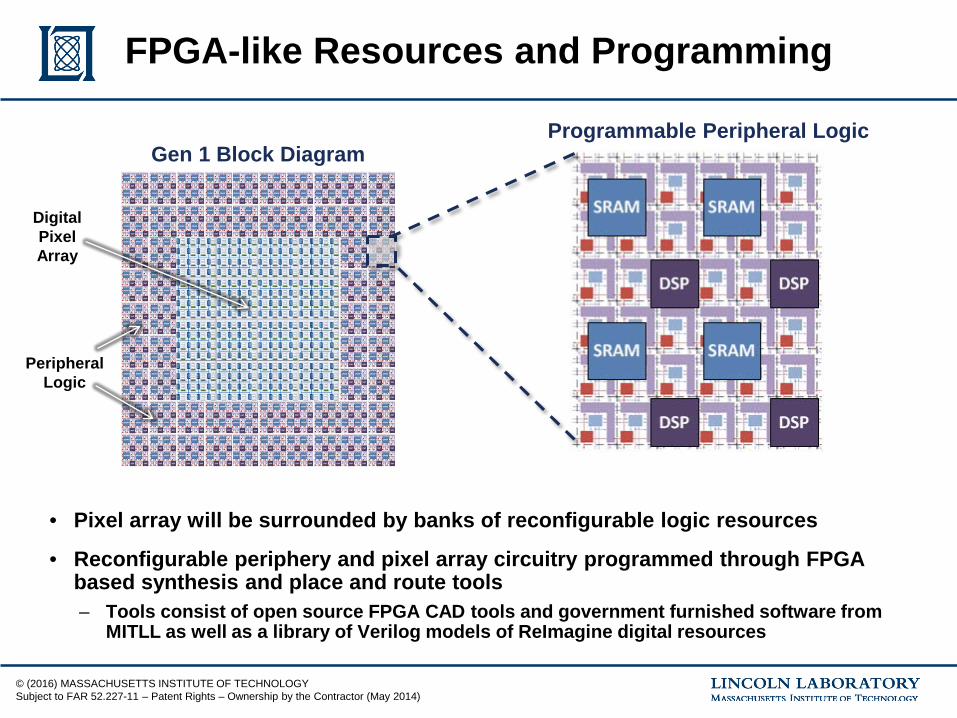
FPGA-like Resources and Programming
Programmable Peripheral Logic
• Pixel array will be surrounded by banks of reconfigurable logic resources
• Reconfigurable periphery and pixel array circuitry programmed through FPGA based synthesis and place and route tools– Tools consist of open source FPGA CAD tools and government furnished software from
MITLL as well as a library of Verilog models of ReImagine digital resources
Gen 1 Block Diagram
Digital Pixel Array
PeripheralLogic
© (2016) MASSACHUSETTS INSTITUTE OF TECHNOLOGYSubject to FAR 52.227-11 – Patent Rights – Ownership by the Contractor (May 2014)
• MITLL leveraging extensive background in digital pixels to develop next generation reconfigurable integrated circuits for ReImagine
• Gen 1 IC will provide arrays of dynamically reconfigurable counter resources surrounded by peripheral programmable logic
• Gen 2 IC will expand and Gen-1 concepts and replace some of the counter resources in the pixel array with more complex digital blocks (e.g. memories, adders, multipliers, etc)
• Reconfigurable ICs will be programmed through a combination of open source FPGA CAD tools and government-furnished software from MITLL
Summary