recovery and diagnostics in the central control of the axe
TRANSCRIPT

IEEE TRANSACTIONS ON COMPUTERS, VOL. C-29, NO. 6, JUNE 1980
Recovery and Diagnostics in the CentralControl of the AXE Switching System
BENGT E. OSSFELDT AND INGMAR JONSSON
Abstract- AXE is a stored program controlled (SPC) telephoneexchange system. Its control system typically comprises 100 000 ICpackages with MTBF = 200 h. The application allows the controlsystem to contribute to the system outage with only a few minutes peryear. An ordinary telephone technician is able to maintain the system,mainly during normal working hours.The control system consists of a duplicated central processor and
a number of regional processors. It has secure fault detection and re-covery and efficient diagnosis of permanent and temporary faults. Thisis verified by physical fault simulations and field experience.
The modular structure of the system eases its handling during design,manufacturing, installation, and operation and makes it well fitted forfurther development.
Index Terms- Concurrent diagnosis diagnostic programs, diag-nostics performance evaluation, fault-tolerant computing, intermittentfatlt, maintainability, maintenance software, physical fault insertion,self checking.
INTRODUCTION
T HE AXE system consists of two main parts, the controlsystem APZ 210 and the application system APT 210,
which are structured into a number of subsystems.These comprise hardware (Fig. 1) and software stored in
the regional and central processors.The maintenance subsystem MAS consists of software in
the central processor and a hardware unit, maintenance unitMAU. The task of MAS is to handle faults in RPS and CPS.It should enable operation to continue with as few and smalldisturbances as possible, as well as produce alarm printoutswith diagnostic information.
Since the alarm printouts indicate suspected circuit boardsby means of their functional names and location, there is noneed for a faulty dictionary [1].MAS comprises a total software volume of 50K 16-bit words
of programs and 20K 16-bit words of data. There are no ad-ditional programs or data stored on secondary media such astape or disk.The properties of the system can be summarized in the fol-
lowing characteristics.1) Duplication of the central processor applying the parallel
synchronous method for secure and immediate detection ofhardware faults by matching the two processors, and to enablerepairs in one processor without affecting the operation of theother.
Manuscript received July 11, 1979; revised November 30, 1979.-The authors are with the ELLEMTEL Development Company, Stockholm,
Sweden.
2) A spare bit in the program store and data store whichassures parallel synchronous operation even in case of a bitfault in a store.
3) Redundancy of regional processors, controlled by soft-ware in the central processor.
4) Automatic reloading of programs and permanent datain addition to automatic system restart after repeated programfailures or total power failure.
5) Modular CPU structure in the central processor enableseffective diagnostics (fault localization) with minor couplingto failure modes and details in hardware.
6) Automatic record keeping and diagnosis of temporaryfaults by built-in aids for analysis of the recorded informa-tion.
7) Automatic checks and diagnosis of check circuits andother maintenance hardware, thus forming a system with highchecking coverage.The description emphasizes the maintenance functions for
the central processor (CP) since they are of major interest froma fault-tolerant computing viewpoint.
HARDWARE STRUCTURE OF APZ 210
The circuit boards are contained in mechanical units (bays)called magazines, which also interconnect the boards electri-cally. The magazines are interconnected by means of stan-dardized plug-in cables.APZ 210 consists of the following magazines: central pro-
cessing unit (CPU), program store (PS), reference store (RS),data store (DS), regional processor bus interface (RPI),maintenance unit (MAU), regional processors (RP), and 10interfaces (Fig. 1). The CPU consists of 31 large circuit boardscontaining up to 154 IC's each. The other magazines contain10-20 boards with a maximum of 44 IC's per board.The regional processors (RP) handle the direct control of
the hardware units (IO devices, line circuits, switches, etc.).The RP program (PROM-stored) mainly execute uncompli-cated and frequent tasks such as line scanning, digit reception,and line signaling. To prevent a single fault from influencingmore than one hardware unit in the application system, theRP's can work in pairs. Normally, the RP's in a pair controlone half each of the common equipment, and in case of a faultin one RP, the twin is ordered to take the entire load.The CP architecture (Fig. 2) enables high capacity and
protection by division of the main storage into program store(PS), reference store (RS), and data store (DS). Each of theseis controlled by an autonomously working handler: PSH
0018-9340/80/0600-0482$00.75 © 1980 IEEE
482

OSSFELDT AND JONSSON: AXE SWITCHING SYSTEM
APT 210 Sub systemsSSS Subscriber SwitchGSS Group SwitchTSS Trunk Switch
DSPSRSCPBRPBMAUCPUTCUALUBAMMIGPCUTRUDSH
APZ Sub systemsRPS Regional ProcessorslOS Input-OutputCPS Central ProcessorMAS Maintenance
Data StoreProgram StoreReference StoreCentral Processor BusRegional Processor BusMaintenance UnitCentral Processor UnitTable and Counter UnitArithmetic Logic UnitMaintenance Buffer UnitMicro Instr. GeneratorPriority Control UnitTrace UnitData Store Handler
LIUPSHUPMRSHSBUPTHRPC
RPI
CMPTBUMBCP
Link and lnstr. Addr. UnitProgram Store HandlerUpdating and Match UnitReference Store HandlerShift and Bit Handling UnitProcessor Test HandlerRegional ProcessorControllerRegional ProcessorInterfaceControl MemoryProcessor Test BusUpdating and Matching BusCentral Processor
Fig. 1. AXE hardware block diagram.
fetches machine instructions and decodes them, RSH calcu-lates addresses to variables in DS, and DSH fetches and storesvariables of various sizes in DS. The CPU is consistentlystructured into a number of separate functional units whichcan interact only via the central processor bus CPB. This is animportant feature, and the use of it as a key to simple and ef-ficient diagnostics for permanent and temporary faults is de-scribed below.
Dynamic MOS-RAM (today 4K bits packages) are utilizedin the stores. DS and PS words are 16 bits + 1 parity bit + 1spare bit. These stores are extendable up to 1024K by storemodules of 128K (magazines). Each module contains a powersupply, 16 memory boards, and 4 boards for bus circuits, dataregisters, timing, and a spare bit control register (SCR). TheSCR contains five bits: one for connection and disconnectionof the spare bit, and four to select the data bit column to bereplaced by the spare bit. The SCR can be written from theCPU to eliminate bit faults in one module independently ofother store modules.The spare bit feature is not implemented in RS as its fault
rate is considerably lower than that of the other stores. RScontains typically only 16K 32 bit words, physically organizedas 32K words of 16 bits + 1 parity bit.CPS includes a processor test unit (PTU) (Fig. 1). It consists
of a panel with a few pushbuttons and indicators and an al-phanumeric display terminal supported by software in one RP.The PTU is used for initial load and start of the system. It isalso used by the system to fetch diagnostic information.
THE MAINTENANCE UNIT (MAU)
The concept with one central unit containing hardware forautomatic and manual maintenance functions fits the generalphilosophy of modular design. MAU has been designed bypeople with a particular interest and responsibility in themaintenance facilities with minor interference with the CPUdesign.
Fig. 2. APZ 210-Central hardware.
The interacting functions in the CPU are implemented es-sentially in microprogram. The hardware interface is locatedon two CPU boards, one each for the automatic and themanual maintenance. The MAU-CPU interface is carefullydesigned with respect to mutual fault protection. It also makesroutine testing of MAU possible. MAU is the active part indeciding the new CP configuration at recovery from CPfaults.The two CP's are called Side A and Side B from a physical
viewpoint. Logically, they adopt different working states sothat one is executive, EX, and the other is standby, SB. Thelatter can adopt the following substates:
WO = Parallel Working UP = UpdatingSE = Separated HA = Halted
These 2 + 4 working states are stored in MAU in one registercontaining 1 + 2 bits. This means that there is always one (andonly one) EX, which always can be considered as "working"since it has no substates like the SB. This working state in-formation is transferred statically to the CP's via the unit BAM(Fig. 2).
Error signals from checkers in CP are received in MAU (viaBAM) and stored in error signal registers. When hardwaredetects a CP fault, MAU controls the recovery procedure untilone fault-free CP has returned to normal program execution.Then MAS software takes over for diagnostics and possiblyreestablishing parallel operation. The recovery control is im-plemented as a sequential logic which performs the followingsteps, started by an error signal. (Only typical fault handlingin the normal parallel working state is- described here.)
1) Order an interrupt to the malfunction level, which hasthe highest priority. This is timed so that the two CP's willinterrupt after the same machine instruction (if saneenough).
2) Supervise acknowledgment signals from the CP's.3) Wait for "I am sane" or fault signals from the CP's.4) Choose one CP and order it to return from interrupt.
483

IEEE TRANSACTIONS ON COMPUTERS, VOL. C-29, NO. 6, JUNE 1980
Fig. 4. Updating and matching.
Fig. 3. MAU fault isolation principle.
5) Supervise acknowledgment signal and operate workingstate register (invert the EX bit- if necessary and set substateHA).
During the recovery procedure, MAU is in a supervisorystate in which it accepts only expected error signals and ac-knowledgments from CP.
In all other MAU states, the software in CP has access toMAU registers via BAM by means of read and write instruc-tions. These are used for all software-controlled operationsconcerning the maintenance status of the CP and for testingthe MAU. The system can detect and isolate faults in theMAU and repairs, and taking it into operation can take placewithout disturbing the program execution. An essentialfunction to solve this problem is the MAU working state logic(Fig. 3). The basic principle is that the CP's are to protectthemselves against faults in MAU. The BAM unit can,therefore, inhibit signals from MAU. Then a standard con-
figuration is selected with CP-A as EX and CP-B as SB-WO.This status is always assumed as far as possible, i.e., after eachfault in CP, MAS shall make an attempt to restore thisworking state and then deactivate MAU. When a fault signalfrom CP is received in MAU, it autonomously sets the state"activated" so that it can control the recovery procedure.
If a fault occurs in MAU when it is deactivated, this cannotinfluence the processors. During a test of MAU, the workingstate "check"' is set in both CP sides. The function of MAU canthen be tested with write and read operations without dis-turbing the processors. When MAU is considered as faulty,the "check" state is retained until the unit is verified by thesystem after repairs.The cross connection of the "check" state is used to prevent
an individual CP side from isolating itself from MAU in anunauthorized manner. The voltage checker in MAU providesinformation to the CP's that they are to isolate themselves fromMAU.The routine test interval is optimally selected to minimize
the risk that a CP fault occurs during a MAU test and to
maximize the probability that a MAU fault is detected andrepaired before a CP fault occurs.The task of the manual maintenance part of MAU is to
transfer signals between the processor test unit (PTU) and theappropriate CP side, which normally means CP-SB. To getcertain commands accepted, such as reset MAU or request toaccess CP-EX, the operator needs a turnkey. Misuse of this,causing, for instance, a stop of CP-EX, will result in a systemrestart, at which the system isolates itself from further inter-ference.
SYNCHRONIZATION AND UPDATING
The central processor is structured in a number of functionunits that interact via a bus (CPB), Fig. 2. The bus is divided.into a control bus of 20 bits and a data bus of 33 bits whichincludes 13 bits for interrupt signals, etc.A typical microcycle (250 ns) in CP begins as the MIG
reads a microinstruction from the control memory CM andsends it on the control bus. Two function units are therebyaddressed: one as sender of data and one as receiver. The de-coding of the microinstructions is thus distributed into thefunction units. The internal work in the function units is au-tonomous to a great extent, and the interwork via CPB isasynchronous. Each CP side is always controlled by its ownlocal oscillator, even at the state of parallel operation.
This means that the updating and matching units (UPM),Fig. 4, have to cope with two CPU's, each working at its ownpace. An essential part of UPM is, therefore, a stretchablefirst-in first-out buffer through which data from CPB in theEX-side are transferred to the SB side for matching (andupdating). The necessary synchronization utilizes the hand-shake method.The function is as follows. Assume that a sending function
unit (S) and a receiving function unit (R) have been indicatedby MIG. This supervises the busy signals ROCC and SOCC.At the ceasing of them, MIG sends the data input pulse DI toinform the receiver that it must clock in data from CPB. (Thebusy signals mark that the sender or receiver is not yet readyto accept the prevailing order, while DI marks that a mi-croinstruction has been completed.)On every DI pulse, UPM also clocks in data from CPB re-
gardless of the units which have been indicated by the mi-croinstruction. These data are transferred from the EX side
484

OSSFELDT AND JONSSON: AXE SWITCHING SYSTEM
to a buffer, BUM, in the SB side. BUM consists of eight 33-bitregisters. The loading ofBUM is controlled by DI from the EXside, and reading is controlled by DI from the SB side. DI (butno data) is sent from SB to EX. By counting the DI pulses fromthe home side and from the twin, UPM can determine whetherthe home side is running faster than the other, which will resultin overflow or underflow in the buffer BUM. To prevent run-
away, UPM in the faster side simulates a busy signal ROCC,and thus delays the next DI pulse.The design is thus adapted to the asynchronous interaction
between the function units via CPB, which in turn enables theautonomous work of the units, internally and towards associ-ated store units (with autonomous refresh). Note that CP-SBalways is a few microcycles after CP-EX in real time becauseof the "rubberband" function of BUM. UPM in the SB sideis the only place where information from the correspondingmicrocycles in EX and SB is available simultaneously formatching. All the 33 transferred bits (data and interrupt sig-nals) are matched for each microinstruction, except for certainoperations that give no relevant data on CPB (e.g., internalMIG operations like jumps, etc.).The parallel start procedure comprises updating, verification
with parallel operation, and a rough fault localization. Theprocedure starts with CP-SB halted, HA. Thereby, certaincontrol registers are initialized by hardware in the CP, amongothers, the updating register UPD which is part of eachfunction unit. This means that the transmitters towards CPBwill be disabled in all units (except UPM), Fig. 4. The UPDregisters in CP-EX are set by programs. This will not disablethe transmitters as the standby-updating condition SBUB(from MAU) is false in CP-EX. CP-SB is started as its sub-state is changed to Updating, UP (by means of a write opera-
tion from CP-EX towards MAU). It will then reach a specificaddress in the microprogram and cannot proceed since thebuffer BUM is empty and UPM is sending busy signalROCC.CP-EX soon passes the same microprogram address and will
then activate its UPM so that data and control pulses are beingsent to its twin. SUB (information on the status of the UPDregister) is included in the 33 bits sent to CP-SB. Its functionis to activate the UPM transmitters towards CPB.CP-SB can now execute microprograms immediately at the
pace of EX as described earlier, but with the exception thatUPM sends data on CPB instead of the units that are indicatedby the microinstructions from MIG. Through the normal ex-
ecution of programs by CP, all registers and store cells inCP-SB will successively become loaded with the same data as
in CP-EX. This is specifically guaranteed by the routine testprograms.
The verification of CP-SB takes place as the UPD registersare cleared unit by unit (in parallel in EX and SB) so that theunits will become active towards CPB. The use of this for di-agnostic purposes is described below.The synchronization microprogram (Fig. 5) is used for all
software-initiated CP reconfigurations. It is called by an in-
terrupt signal from MAU when a new code is written in theworking state register. The case shown is the start of haltedCP-SB simplified. CP-EX clocks the altering of the working
EX SOCCIRE MAI SY MA MA I AU Ml M2| M3| M4 M5
RdECT VSYS DII DI Dl 1DI
ROCC ROC1GRS I,MR| MRI AU1 Ml M21 M3 M4 I M5SB-HA SB-UP
Micro Orders:GRS General reset RE ReconfigurationRECT Reconfiguration timing MA AuxiliarySYS Synchronized start MR RandomDl Data Input Clock SY SynchronizationROCC Receiver occupied AU Activate UPMSOCC Sender occupied Mi-M5 First five orders
in synchronism
Fig. 5. Synchronized start microprogram.
state signals from MAU in order to get at an appropriate time.The synchronized start order is a pulse, which forces theCP-SB to jump to a fixed microprogram address where it ac-tivates UPM. CP-EX then passes the same address and acti-vates its UPM. When information has been transferredthrough the UPM's, CP-SB can "hang on." As an example ofhow UPM compensates for variations in the microcycle pace,orders M3 and M5 in CP-EX and CP-SB are shown to be de-layed by some internal cause.
FAULT DETECTION
Hardware, microprograms, and software are used for faultdetection in APZ 210.
There are three classes of hardware checkers.1) PHC, program handling check circuits (watchdogs) for
overall supervision of processors. They must be triggered bysoftware regularly in order not to release.
2) Unit (or side) indicating checkers for supervision of dcvoltage supplies, parity codes in stores and buses, and ac-knowledgment signals for asynchronous interfaces betweenunits.
3) Matching circuit, which is the most efficient functionfor detection of hardware faults in CP.At fault detection in CP, certain interesting information is
saved. For store faults, for example, freezing is made of thestore address in an address save register. Storage of informa-tion on the data bits or interrupt signal bits that caused mis-match tak&s place in UPM. In addition, there are two re-cording memories with 16 positions. One of them stores foreach microinstruction information on the unit which is sending(sender address), and the other stores for each machine in-struction the address to the starting point in CM for the re-spective microprogram. They provide a good picture of whathappened in CP before mismatch occurred.The microprograms are capable of detecting incorrect ac-
cessing of variables and program sequences, e.g., referencinga variable with too high index or calling a vacant signal entrywill not be executed, and instead a software error signal is sentto a block in the operating system (CPS).The above-mentioned functions are the primary tools for
detecting hardware faults in data processing parts ofAPZ 210.The execution of application programs under the supervisionof these circuits is a good routine test of the control system.Routine tests of all data processing functions in CP and RP are,nevertheless, included in MAS for several reasons: for detec-
485

IEEE TRANSACTIONS ON COMPUTERS, VOL. c-29, NO. 6, JUNE 1980
tion of faults in store cells that are used infrequently, for adefined full test of CP at parallel start, etc. Maintenance in-structions are available for fast and secure test of stores. Thereis also a particular instruction by which a number of specialmicroprograms can be called, and an "execute microorder"instruction.
Check circuits are tested in the parallel start. PHC ischecked by not triggering it. Time supervision of responsesfrom RP's and stores are checked by accessing an unequippedaddress. For checking the time supervision of microcycles (theDI pulse) in MIG, there is a dummy order to BAM that givesan extremely long busy signal, ROCC. For parity checkers,there is a test state in which even parity is generated insteadof odd. Voltage checkers are not tested.
Larger complexes of auxiliary circuits such as the processortest equipment PTU and the maintenance unit MAU areroutine-tested. This takes place at optimal routine test inter-vals: 24 h for PTU and 4 h for MAU. Exercising of all thevarious working states for CP is included in the 24 h routinetests.
FAULT HANDLING CP
At malfunction interrupt, the CP's execute self tests (SDP)independently of each other (Fig. 6). These tests are essentiallythe same as the routine tests. The CP's inform MAU that a testhas failed or that SDP is passed OK. As soon as MAU hasinformation on which CP side is faulty ("side indication" fromthe program or checkers), however, it will order the fault-freeCP to skip the remaining tests and return to the interruptedprogram. In case CP-EX is faulty, a switching of the EX stateis done (crossing dashed lines). Because of the full duplicationof CP, a large majority of the faults will cause no other dis-turbance to the application programs, but a real time loss ofa few or up to 40 ms. This can be considered as a "transparentrecovery." If the fault cannot be traced to a particular CP side,a "blind choice" of the prevailing EX is made. As there is acertain risk that EX is the faulty one, the first minute after anerror interrupt is regarded as a period of trial traffic while theSB is resting in its halted state. If any fault is manifested duringthis time, side switching and software recovery are executed(system restart).
After the recovery, a parallel start attempt is made. This willindicate whether the fault remains or not. Parallel operationis reestablished if the fault was temporary or a permanentsingle-bit fault in PS or DS. An alarm printout with diagnosticinformation is issued after a permanent fault and after anumber of temporary faults. The "alarm class" informs theoperator of the urgency for repairs. A halted CP should berepaired within 2 h. The majority of the faults can, however,be taken care of at daytime, as they are covered by the sparebit or diagnosed as temporary fault. The repairs are verifiedby means of a parallel start attempt.
SYSTEM RESTART
At detection of incorrect data processing in CP by watchdogor microprogrammed checks, the system is restarted. Thereare three ranks of restart.
SB-HA
| REPAIR 1
MAEPAE etc ro
1 t W 7 ~~~~~~~~~~~~~~~Faultyunit
SB-WO SB-HADtm-UP
Fig.tnJ 6.TyialCfaulty hadig1)Sal,acllls inpprogresstare retained2)eLarger, allgcall are disonnected3)carewihreodig iaulag resarltporecdeboami
EX
MAE Match errorPAE Parity errorSDP Side Determining
test programRECPI Repair check command
Fig. 6. Typical CP fault handling.
1) Small, calls in progress are retained.2) Large, all calls are disconnected.3) Large with reloading, a large restart preceded by a mi-
croprogram-controlled loading of programs and permanentdata from cartridge or magnetic tape.A system restart embraces a hardware recovery which
consists of a side switching of CP and a restart and testing ofall RP's, as well as a software recovery which means restartof all blocks.
Sporadic system restarts are carried out as small restarts.If a second or third restart occurs within a short time (10 min),the higher ranks are chosen.
GENERAL ON DIAGNOSTICS
When designing the diagnostic functions, attention has beenpaid to the following.
1) Temporary faults should be diagnosed by the system.2) Diagnostics designers should not need to consider the
details of the hardware implementation.3) The internal structure and failure modes of complex
integrated circuits are not always known in detail.4) Some expert aids should be incorporated in the
system.5) The software should be simple and inexpensive to
maintain.
CP DIAGNOSTICS
General
The well-known concept of applying a large number of di-agnostic tests from one unit to another unit in a combinatoricor sequential way [1], [7] is not used. According to our method,it is more a matter of one machine manipulating its internalredundancy and collecting and analyzing symptoms of fail-ures.The CP diagnostics is essentially based on two methods: unit
localization and address analysis (store address or CPU senderaddress). These utilize hardware features such as UPD reg-isters, freezing of store address in handlers, and freezing ofsender address in UPM at error detection.Note that as the diagnostics rely on the matching of the CP
sides, it will locate a fault to the actual boards even if the faulthappens to be in the EX side!
486
OSSFELDT AND JONSSON: AXE SWITCHING SYSTEM
Permanent Faults
The unit localization is a part of the parallel start procedure.Verification of CP-SB takes place after the updating by re-
setting the UPD registers in unit by unit at such a pace thateach unit will be satisfactorily tested by routine test programsand application programs under supervision of matching cir-cuits and other checkers. This means that the software (andhardware) environment in which the fault originally was de-tected is also used to verify whether the fault remains or not.If a fault manifestation is obtained, the fault is regarded to bepermanent, and the unit that was activated last is suspectedto contain the fault.
If the suspected unit contains one board, the diagnostic iscompleted. Otherwise, further diagnostics is needed. 6 CPUunits contain one board, 5 units 2 boards, and 3 units 3-5boards. In addition, some units have store modules connectedto them. The further diagnostics of the multiboard units utilizethe fact that UPD registers consist of a number of bits whichcan be reset one at a time. Each of these activates a specificfunction of a unit. Thus, it can be observed which bit is un-masking the fault, and the fault is thereby localized to a spe-
cific part of the unit.The final diagnostics of a suspected unit is carried out in two
steps. All other units are deactivated by their UPD registers.The matching of CPB is used for fault indication.The first step comprises a number of short tests. The unit
is activated by means of its UPD register during each test only.The bus interface is checked first. Then specific functions are
exercised. Data and address tests of the store are made if theunit is a store handler. Except for the store tests, the diagnosticis terminated when one test has failed. Fault weights are as-
signed according to fault weight tables.The second step is a test period during which the unit is
activated while ordinary application programs and routine testsare executed. At fault detection, an analysis is made of error
signals and sender address.A typical diagnostic printout has the following shaping:
ALARM APZ A
CP UNIT FAULT
MAGAZINE BOARDCPU*B LIUICPU*B LIU2
WEIGHT955
END
A fault has been detected in CPU, B side. It has been localizedto unit LIU and the boards LIU1 and LIU2 are indicated as
faulty. The "alarm class" A means urgent repairs are
needed.
Temporary Faults
At malfunction interrupt, the microprogram has stored a
large number of data. Then the MAU has stopped one CP side.CP-EX can thus fetch the required data from SB via the PTU(Fig. 1) before starting it to parallel operation (Fig. 6).
Temporary faults are grouped into fault types according toerror signal in the MAU. Specific interesting data are asso-ciated with each fault type.
After each temporary fault, the diagnostic programs checkif the number of faults of the current type has reached an alarmlimit. If so, all data recorded for the current fault type areanalyzed, and for each record, fault weights are assigned tothe suspected circuit boards according to the fault weight ta-bles. If the analysis indicates a temporary single bit fault, thespare bit is connected in the faulty magazine.
Indication of which side is faulty cannot be obtained for anumber of temporary faults, especially in the CPU. This,however, does not prevent a good diagnosis of the fault sincethe freezing of the sender address in UPM at mismatch alwaysindicates the faulty unit. Thus, boards in both CP-A and CP-Bare mentioned in the alarm printout after a number of suchmismatches.
Fault Weight Tables
The diagnosis of the CPU relies on two types of weight tableswhich are indexed by the sender address or test number. Thetables contain names of magazines and boards and faultweights. For a given index, the fault weight represents thelikelihood for the board to contain the fault. The weights areset manually by estimating failure rates of the circuits whichcan cause the fault manifestation.The sender address table is based solely on studies of circuit
drawings. The sender address indicates a unit and a sourceregister. Data sent from one register have been processed bycertain circuits. The drawings show whether these circuits arelocated on one board or distributed on a number of boards. Atotal sum of 100 is allotted to the boards involved for eachsender address.The tables indexed by test numbers are based on which
circuits are exercised by each test. Fault weights are assignedaccording to the same principles as above.
MAU DIAGNOSTICS
Diagnostics of the automatic maintenance part ofMAU isconventional: stimuli are applied to various points in the logicand the response is checked at other points.The complete MAU check consists of a number of tests.
Each test will check a specific function. For each failed test,fault weights are allotted to suspected boards. The weights aresummed for each board for all failed tests.
MANUAL AIDS
The automatic diagnostics functions may fail for somespecial faults. Manual aids are built into MAS to handle thosefaults.
Synchronization and parallel start attempts of CPU (withunits excluded) as well as MAU tests may be ordered to runrepeatedly. Thus, interesting sequences of events can bemeasured, for instance, by means of an oscilloscope. MASrecords a number of data at every failure event. This kind ofdata is normally kept within the system, but dumping can beordered.
487
IEEE TRANSACTIONS ON COMPUTERS, VOL. C-29, NO. 6, JUNE 1980
SUCCESSFUL DIAGNOSTICS 94%
80 -
70
60 .
50 1
40
30 .j.
20 1
10
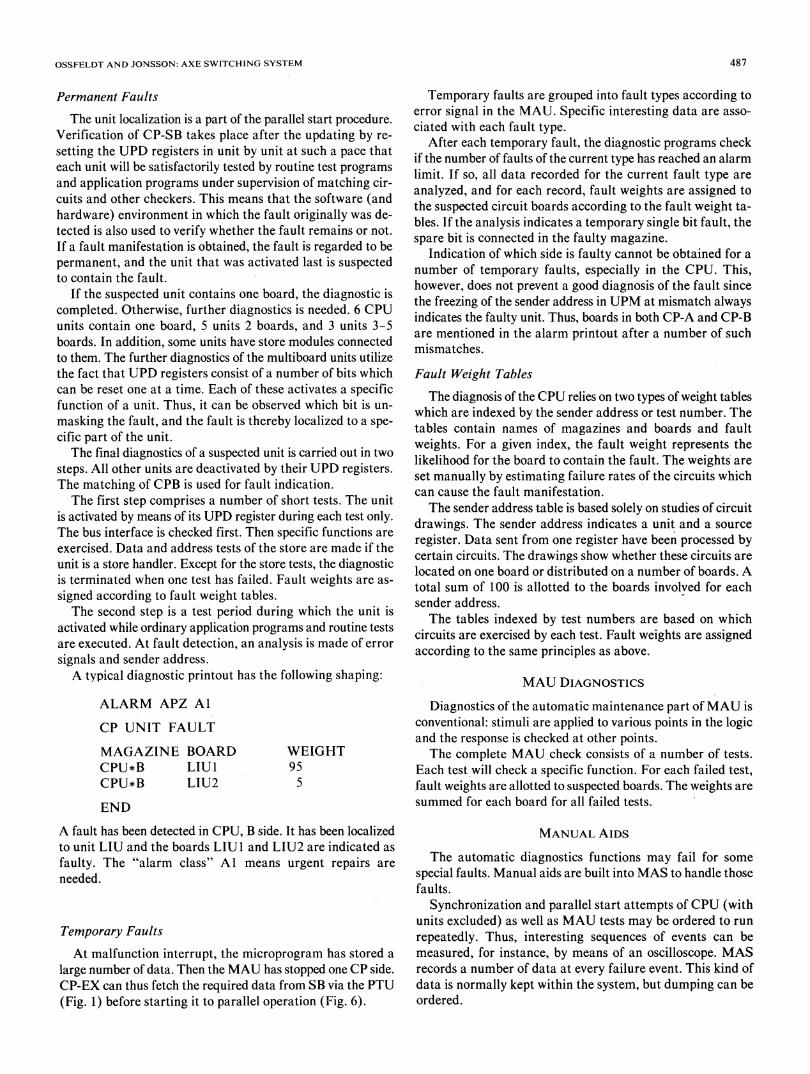
Fig. 7. Diagnostic result-permanent faults.
The following example shows how the ability to exclude a
CP unit logically and to remove it physically from one CP sideduring parallel start attempts is used to localize a fault.Assume that a CPB transmitter in a unit becomes faulty so
that it disturbs a data bit, even when the function unit is notindicated by a microinstruction. Neither the analysis of theregistered sender addresses nor the unit localization procedurewill then produce a clear diagnosis. It is also difficult to use anoscilloscope or logic analyzer to determine the location of thefault.
In such a case, the repairman can request parallel start bymeans of a command which specifies "exclusion" of functionunits. The UPD register is not reset in these units. Thus, theycan be removed physically from CP-SB while the other unitsare working in parallel with CP-EX. By ordering test runs withexclusion of various function units, the repairman can locatethe unit which is disturbing the bus. It is not necessary that a
test program produces the disturbance, but the fault can de-pend on data or sequence and may only manifest itself in an
application program, for example. This procedure is not ap-plicable to MIG and UPM.
FAULT SIMULATION METHOD
In order to evaluate the diagnostic functions, an extensivefault simulation program has been carried out. Both permanentand temporary faults have been simulated. All circuit boardsin the magazines CPU, PS, DS, RS, RPI, MAU, and RP were
tested (Fig. 2).The diagnostic functions ofAPZ 210 are, in general, inde-
pendent of the details of the hardware and of its failure modes.Thus, we have limited the failure modes for the fault simula-tion to s-a-0.The integrated circuits on circuit boards are interconnVcted
via networks, i.e., one output from an IC is connected to oneor more inputs (if the output is of the open collector or three-state type, several outputs may, of course, be connected). Anumber of networks were selected at random for fault simu-lation. In CP, permanent faults were introduced in 3600 net-
PERCENT OFFAULTS
NO OFBOARDSINDICATED
1 2-4 4-8 >8
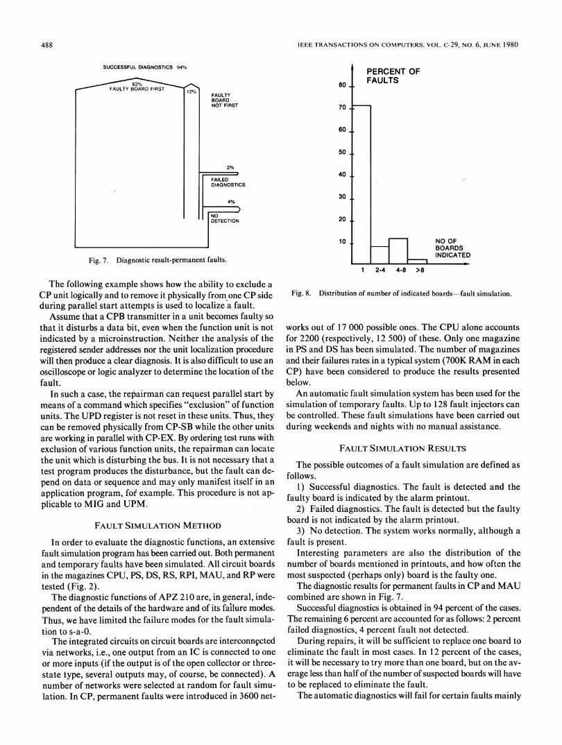
Fig. 8. Distribution of number of indicated boards-fault simulation.
works out of 17 000 possible ones. The CPU alone accountsfor 2200 (respectively, 12 500) of these. Only one magazinein PS and DS has been simulated. The number of magazinesand their failures rates in a typical system (700K RAM in eachCP) have been considered to produce the results presentedbelow.An automatic fault simulation system has been used for the
simulation of temporary faults. Up to 128 fault injectors canbe controlled. These fault simulations have been carried outduring weekends and nights with no manual assistance.
FAULT SIMULATION RESULTS
The possible outcomes of a fault simulation are defined asfollows.
1) Successful diagnostics. The fault is detected and thefaulty board is indicated by the alarm printout.
2) Failed diagnostics. The fault is detected but the faultyboard is not indicated by the alarm printout.
3) No detection. The system works normally, although afault is present.
Interesting parameters are also the distribution of thenumber of boards mentioned in printouts, and how often themost suspected (perhaps only) board is the faulty one.The diagnostic results for permanent faults in CP and MAU
combined are shown in Fig. 7.Successful diagnostics is obtained in 94 percent of the cases.
The remaining 6 percent are accounted for as follows: 2 percentfailed diagnostics, 4 percent fault not detected.
During repairs, it will be sufficient to replace one board toeliminate the fault in most cases. In 12 percent of the cases,it will be necessary to' try more than one board, but on the av-erage less than half of the number of suspected boards will haveto be replaced to eliminate the fault.The automatic diagnostics will fail for certain faults mainly
488
OSSFELDT AND JONSSON: AXE SWITCHING SYSTEM
80
70
60
50
20
10
PERCENT OFFAULTS
NO OFBOARDSINDICATED
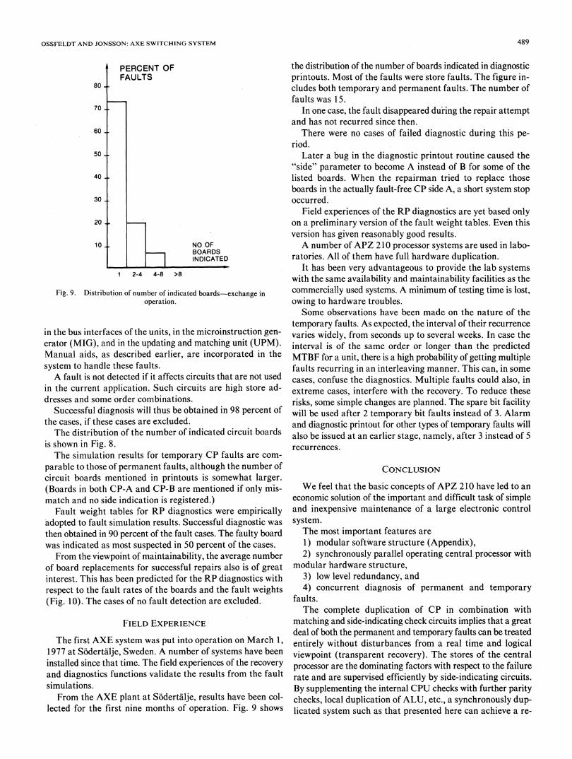
1 2-4 4-8 >8
Fig. 9. Distribution of number of indicated boards-exchange in
operation.
in the bus interfaces of the units, in the microinstruction gen-
erator (MIG), and in the updating and matching unit (UPM).Manual aids, as described earlier, are incorporated in thesystem to handle these faults.A fault is not detected if it affects circuits that are not used
in the current application. Such circuits are high store ad-dresses and some order combinations.
Successful diagnosis will thus be obtained in 98 percent ofthe cases, if these cases are excluded.The distribution of the number of indicated circuit boards
is shown in Fig. 8.The simulation results for temporary CP faults are com-
parable to those of permanent faults, although the number ofcircuit boards mentioned in printouts is somewhat larger.(Boards in both CP-A and CP-B are mentioned if only m'is-match and no side indication is registered.)
Fault weight tables for RP diagnostics were empirically'adopted to fault simulation results. Successful diagnostic wasthen obtained in 90 percent of the fault cases. The faulty boardwas indicated as most suspected in 50 percent of the cases.
From the viewpoint of maintainability, the average numberof board replacements for successful repairs also is of greatinterest. This has been predicted for the RP diagnostics withrespect to the fault rates of the boards and the fault weights(Fig. 10). The cases of no fault detection are excluded.
FIELD EXPERIENCE
The first AXE system was put into operation on March 1,1977 at Sodertalje, Sweden. A number of systems have beeninstalled since that time. The field experiences of the recoveryand diagnostics functions validate the results from the faultsimulations.
From the AXE plant at S6dertalje, results have been col-lected for the first nine months of operation. Fig. 9 shows
the distribution of the number of boards indicated in diagnosticprintouts. Most of the faults were store faults. The figure in-cludes both temporary and permanent faults. The number offaults was 15.
In one case, the fault disappeared du'ring the repair attemptand has not recurred since then.
There were no cases of failed diagnostic during this pe-riod.
Later a bug in the diagnostic printout routine caused the"side" parameter to become A instead of B for some of thelisted boards. When the repairman tried to replace thoseboards in the actually fault-free CP side A, a short system stopoccurred.
Field experiences of the RP diagnostics are yet based onlyon a preliminary version of the fault weight tables. Even thisversion has given reasonably good results.A number of APZ 210 processor systems are used in labo-
ratories. All of them have full hardware duplication.It has been very advantageous to provide the lab systems
with the same availability and maintainability facilities as thecommercially used systems. A minimum of testing time is lost,owing to hardware troubles.Some observations have been made on the nature of the
temporary faults. As expected, the interval of their recurrencevaries widely, from seconds up to several weeks. In case theinterval is of the same order or longer than the predictedMTBF for a unit, there is a high probability of getting multiplefaults recurring in an interleaving manner. This can, in somecases, confuse the diagnostics. Multiple faults could also, inextreme cases, interfere with the recovery. To reduce theserisks, some simple changes are planned. The spare bit facilitywill be used after 2 temporary bit faults instead of 3. Alarmand diagnostic printout for other types of temporary faults willalso be issued at an earlier stage, namely, after 3 instead of 5recurrences.
CONCLUSION
We feel that the basic concepts of APZ 210 have led to aneconomic solution of the important and difficult task of simpleand inexpensive maintenance of a large electronic controlsystem.The most important features are1) modular software structure (Appendix),2) synchronously parallel operating central processor with
modular hardware structure,3) low level redundancy, and4) concurrent diagnosis of permanent and temporary
faults.The complete duplication of CP in combination with
matching and side-indicating check circuits implies that a greatdeal of both the permanent and temporary faults can be treatedentirely without disturbances from a real time and logicalviewpoint (transparent recovery). The stores of the centralprocessor are the dominating factors with respect to the failurerate and are supervised efficiently by side-indicating circuits.By supplementing the internal CPU checks with further paritychecks, local duplication of ALU, etc., a synchronously dup-licated system such as that presented here can achieve a re-
489

IEEE TRANSACTIONS ON COMPUTERS, VOL. C-29, NO. 6, JUNE 1980
1 2 3 4 5 6 7 8 9 10 11 12 13 14 15 16 N
Probability (P) of successful repairs versusnumber of board replacements (N). typical RP
A Stochastic replacementsB Replacement according to expected failure rateC Replacement according to the weighttable
Fig. 10. Probability (P) of successful repairs versus number of boardreplacements (N), typical RP.
SUPERVISORYCIRCUITS
I I
those
Includes programsfor CHECKING
which _
ContainsSOFTWARE <
Fig. 11. SPC self-checking scheme.
covery which is just as transparent as that of a triple modularredundancy (TMR) system.The full duplication of the CP stores is used at functional
changes (Appendix). It also eases the handling of the systemat repairs and extensions.The modular structure of the CP is not aimed at providing
maximal data processing capacity, but at improving main-tainability. It was also advantageous at the design and proto-type testing of the CP and its parallel operation. The matchinggreatly helped to debug the CP from hardware design flaws.In fact, this was accomplished in a quicker and more efficientway than for the RP, which is less complex.
It is naturally easier to distinguish between software andhardware faults in CP than in RP at system tests.A totally self-checking circuit (TSC) forms an independent
component with a self-checking capability. An SPC systemwith high checking coverage, such as the AXE system, can beviewed as an entity with a similar self-checking capability atthe system level (Fig. 1 1).
APPENDIXGENERAL PRINCIPLES OF AXE
The AXE system has a number of principles that contributeto the operational reliability of the system.
It has a functional structure with four hierarchical levels:system, subsystem, function blocks, and function units [2]-[4].The function blocks are implemented as hardware units and
regional and central software function units.The programming takes place mainly in a high-level lan-
guage, PLEX. A programming system called APS [4], [5]supports the software designers with editing, analyzing, testing,and target code generation.
In the AXE system, it is not possible to access or influenceprograms, data, or hardware of another block from a functionblock. Instead, interaction between the blocks takes place solelyby means of software signals which, with respect to meaningand format, are clearly documented for both the programmerand APS.
Function block
Handlingr- of processor
malfunction EES
Tracehandling
EES
Traffic handling
Centralsofware EES
Regionalsoftware
Operation andmaintenance
- , EES
Regionalsoftware
PCU Signals
ProcessorMFL malfunction
T I~~MA
-v7--RL
HLj1
__3A1
2
BA 1
_ 2_
Trace interrupt
Clock interrupt
Urgenttraffic handling_r
Non-urgenttraffic handling
Operation andmaintenance
JBC -j
Routineoperation andmaintenance
JaJD
Buffered signals
PCU Priority Control UnitMFL Malfunction LevelTRL Trace LevelTHL Traffic Handling Level
with sublevels 1-3BAL Base Level with
sublevels 1 and 2
MAU Maintenance UnitTRU Trace UnitJBA Job Buffer AJBB Job Buffer BJBC Job Buffer CJBD Job Buffer DEES. En4of Execution
Fig. 12. Job handling.
PLEX contains statements for sending and receiving signals.The SEND statement is used to inform or make an order toanother block. The RECEIVE statement-indicates the be-ginning of the interacting program section. Signals can alsobe sent to the own block. During the execution in the APZprocessor. SEND implies that destination information anddata indicated in the statement are stored in a job buffer. Aninstruction sequence is terminated with the EXIT instructionwhich consists of a microprogram that fetches the signal in turnin the job buffer, delivers signal data, and starts execution ofthe program sequence in question [4].
The job scheduling in CP is carried out mainly by micro-programs and is based on an interrupt system with four pro-
hich
490

OSSFELDT AND JONSSON: AXE SWITCHING SYSTEM 491
gram levels and a number of job buffers for queue adminis-tration (Fig. 12).
In PLEX, as well as assembler, variables are referred to withsymbolic names. Address calculation is included in the ma-chine instructions. This eliminates a great number of trivialprogramming faults.
Operator errors have often produced serious operationaldisturbances in previous SPC systems. In AXE, a standardizedman-machine language (MML) is used according to therecommendations of the Central Committee of InternationalTelephone and Telegraph [6]. In addition, there has been anaim to simplify the operator's work by means of functionalcommands. Programmed checks of formats and plausibilitymake the system invulnerable to misuse of commands.
Spontaneous printouts are produced only in conjunctionwith alarm, i.e., when the operator must take some mainte-nance action, generally board replacement. For each alarm,there is an operational instruction that contains a step-by-stepdescription of the actions to be taken at repairs. The opera-tional instructions for the operation and maintenance of theAXE exchange are collected in a Maintenance Manual.
Through the structuring of the AXE system into functionalblocks with signal interfaces, it is possible to remove, add, orexchange individual blocks in a working system as long as thesignal interface towards the rest of the system is not influenced.If a change affects the interface between some blocks, up to16 blocks can be exchanged at the same time.
This is the normal procedure for delivery of new or modifiedCP programs to customers. It is a more reliable way to main-tain large software systems than patching.As in previous SPC systems with fully duplicated central
processors, AXE also contains the possibility of exchangingentire program packages with minor disturbances. This is doneby separating a CP side which is then loaded with the newprograms, whereupon the CP is switched over as EX in orderto handle the traffic. At this moment, data can be transferredfrom the old to the new software (via an RP).
REFERENCES
[1] H. Y. Chang, E. G. Manning, and G. Metze, Fault Diagnosis ofDigitalSystems. New York: Wiley, 1970.
[2] K. Sorme and I. J6nsson: "AXE, A functionally modular SPC-system,"presented at the Int. Switching Symp., 1974.
[3] M. Eklund, C. G. Larsson, and K. Sorme: "AXEIO-System descrip-tion," Ericsson Rev., no. 2, 1976.
[4] G. Hemdal, "AXE10-Software structure and features," Ericsson Rev.,no. 2, 1976.
[5] T. Bingefors and M. Eklund, "The software support system for AXE1O,"presented at the Int. Switching Symp., 1979.
[6] CCITT Orange Book, vol. VI. 4.[7] S. Mallella and G. M. Masson, "Diagnosable systems for intermittent
faults," IEEE Trans. Comput., vol. C-27, June 1978.
Bengt E. Ossfeldt was born in Fr6son, Sweden, onDecember 14, 1938. He received the B.S. degreein electrical engineering from HTL, Orebro, Swe-den, in 1959.
From 1959 to 1971 he was with Telefonaktiebo-laget LM Ericsson, Stockholm, Sweden, where heworked with military electronics, and in 1963 withthe fault tolerant facilities for the central controlof the AKE systems. In 1971 he joined ELLEM-TEL Development Company, Stockholm, wherehe is working with the same functions for the AXEsystems.
Ingmar Jonsson was born in Skalmsj6, Sweden, onMay 2, 1949. He received the M.S. degree in elec-trical engineering from the Royal Institute ofTechnology, Stockholm, Sweden, in 1973.He is now working with fault tolerance facilities
for the central control of the AXE systems at EL-LEMTEL Development Company, Stockholm.