recovery/recycle/recharge recuperaciÓn/reciclaje…€¦ · recuperaciÓn y reciclaje 36 vacÍo 37...
TRANSCRIPT
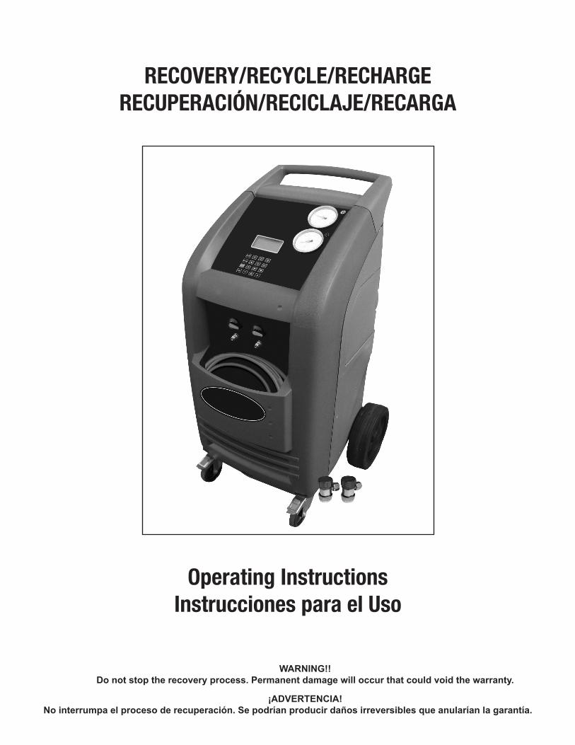
RECOVERY/RECYCLE/RECHARGE RECUPERACIÓN/RECICLAJE/RECARGA
Operating InstructionsInstrucciones para el Uso
WARNING!!Do not stop the recovery process. Permanent damage will occur that could void the warranty.
¡ADVERTENCIA!No interrumpa el proceso de recuperación. Se podrían producir daños irreversibles que anularían la garantía.

2
CONTENTSINTRODUCTION 4
SAFETY SUMMARY 4
SAFETY INFORMATION 4 ELECTRICAL SHOCK HAZARDS 4
MOTION HAZARDS 5
FUME HAZARDS 5
HEAT/FREEZING HAZARDS 5
EXPLOSION/FLAME HAZARDS 5
ADDITIONAL SAFETY INFORMATION 5
CERTIFICATION 6
ABOUT THIS MANUAL 6
ABOUT YOUR AIR CONDITIONING RECOVERY/RECYCLE SERVICE CENTER 6
WARRANTY 6
GENERAL INFORMATION 6
PRINCIPLES OF OPERATION 7
SETUP 7
THE MACHINE 8 BASIC COMPONENTS 8
CONTROLS AND CONTROL SYSTEM 9
FUNCTION SELECTOR KEYBOARD 9
ALARMS 9
PRELIMINARY OPERATIONS 10
AUTOMATIC PROCEDURE 10
ASSISTED PROCEDURE 13 RECOVERY AND RECYCLING 13
VACUUM 13
VACUUM LEAK TEST 13
ADDING NEW OIL 13
CHARGING THE A/C SYSTEM 14
LAST RECOVERED QUANTITY 15
ROUTINE MAINTENANCE 16 FILLING THE MACHINE TANK 16
VACUUM PUMP 17
Oil Fill 17
Checking Oil Level 17
Oil Change 17
REPLACING THE DRYER FILTERS 18
FILLING THE NEW OIL CONTAINER 18
EMPTYING THE USED OIL CONTAINER 19
CHECKING THE SCALE RESPONSE 19
PURGING NON-CONDENSABLE GASES 19
SETTINGS 19 LANGUAGE 19
UNITS OF MEASUREMENT 20 WEIGHT 21

3
PRESSURE 21
TEMPERATURE 21
DATA 21
PASSWORD PROTECTION 22
CUSTOMIZING THE DBA (DATABASE ADVANCED) 23 DATA ENTRY 23
USE 23
DELETION 23
DATABASE UPGRADE 24
CONVERSION CHART 24

4
ÍNDICEINTRODUCCIÓN 27
RESUMEN ACERCA DE LA SEGURIDAD 27
INFORMACIÓN SOBRE LA SEGURIDAD 27 PELIGRO DE CHOQUE ELÉCTRICO 27
PELIGROS DERIVADOS DEL MOVIMIENTO 28
PELIGROS DERIVADOS DEL HUMO 28
PELIGROS DERIVADOS DEL CALOR/HIELO 28
PELIGROS DERIVADOS DEL EXPLOSIÓN/LLAMAS 28
INFORMACIÓN ADICIONAL SOBRE SEGURIDAD 29
CERTIFICACIÓN 29
ACERCA DE ESTE MANUAL 29
ACERCA DE SU EQUIPO DE MANTENIMIENTO PARA LA RECUPERACION/RECICLAJE DEL SISTEMA DEL AIRE ACONDICIONADO 29
GARANTÍA 29
INFORMACIÓN GENERAL 30
PRINCIPIOS DE FUNCIONAMIENTO 30
MONTAJE 30
LA MÁQUINA 31 COMPONENTES BÁSICOS 31
MANDOS Y SISTEMA DE CONTROL 32
TECLADO SELECTOR DE FUNCIÓN 32
ALARMAS 33
OPERACIONES PRELIMINARES 33
PROCEDIMIENTO AUTOMÁTICO 33
PROCEDIMIENTO ASISTIDO 36 RECUPERACIÓN Y RECICLAJE 36
VACÍO 37
PRUEBA DE FUGA DE VACÍO 37
AÑADIR ACEITE NUEVO 37
CARGAR EL SISTEMA DEL AIRE ACONDICIONADO 37
ÚLTIMA CANTIDAD RECUPERADA 39
MANTENIMIENTO ORDINARIO 39 LLENAR EL DEPÓSITO DE LA MÁQUINA 39
BOMBA DE VACÍO 40
LLENADO DEL ACEITE (MÁQUINA NUEVA) 41
CONTROLAR EL NIVEL DEL ACEITE 41
CAMBIAR EL ACEITE 41
SUSTITUIR LOS FILTROS 42
LLENAR EL CONTENEDOR CON ACEITE NUEVO 42
VACIAR EL CONTENEDOR DEL ACEITE USADO 42
CONTROLAR LA RESPUESTA DE LA BALANZA 43
PURGAR GASES NO CONDENSABLES 43
AJUSTES 43 IDIOMA 43
UNIDADES DE MEDIDA 44

5
WEIGHT (PESO) 44
PRESSURE (PRESIÓN) 45
TEMPERATURE (TEMPERATURA) 45
DATOS 45
CONTRASEÑA DE PROTECCIÓN 46
PERSONALIZAR EL DBA (BASE DE DATOS AVANZADA) 46 INTRODUCIR DATOS 47
USO 47
BORRAR 47
ACTUALIZAR LA BASE DE DATOS 47
TABLA DE CONVERSIÓN 47

6
INTRODUCTIONThis machine is ETL Laboratories approved, in compliance with SAE J2788. We are dedicated to solving the issues surrounding the safe containment and proper management of refrigerants. Your new machine incorporates the latest technology and state of the art features to aid you in servicing R134a air conditioning and refrigeration systems.
NOTICE:The SAE J2788 standard has, by design made recycling machines more complex than previous models that some End Users might be familiar with. Some noticeable changes that the End User should expect from ALL new recycling machines are the following.1. RECOVERY TIME: The average recovery time is approximately 30 minutes. This time is necessary to meet the SAE J2788 standard which requires that the machine recovers at least 95% of the AC system refrigerant and cleans the refrigerant to a minimum of 95% purity. 2. HOT WEATHER: As the ambient temperature approaches 100°F, some End Users have experienced an increase in recovery time. This is due to the natural response of R134a when its temperature is elevated. R134a has difficulty transforming from a gas into a liquid state at elevated temperatures. The transformation into liquid is necessary for the machine to complete the recovery process. The End User might notice the same effect when performing a TANK CHARGING operation.3. COLD WEATHER: As the ambient temperature approaches 50°F, some End Users have experienced an increase in recovery time. This is due to the natural response of R134a when its temperature is lowered. R134a has difficulty transforming from a liquid into a vapor state at reduced temperatures. The transformation into vapor is necessary for the machine to complete the distilling process. The End User might notice the same effect when performing a TANK CHARGING operation.
SAFETY SUMMARYThe following safety information is provided as guidelines to help you operate your new system under the safest possible conditions. Any equipment that uses chemicals can be potentially dangerous to use when safety or safe handling instructions are not known or not followed. The following safety instructions are to provide the user with the information necessary for safe use and operation. Please read and retain these instructions for the continued safe use of your service system.
SAFETY INFORMATIONEvery craftsman respects the tools with which they work. They know that the tools represent years of constantly improved designs and developments. The true craftsman also knows that tools are dangerous if misused or abused. To reduce risk of discomfort, illness, or even death, read, understand, and follow the following safety instructions. In addition, make certain that anyone else that uses this equipment understands and follows these safety instructions as well.
READ ALL SAFETY INFORMATION CAREFULLY before attempting to install, operate, or service this equipment. Failure to comply with these instructions could result in personal injury and/or property damage.
RETAIN THE FOLLOWING SAFETY INFORMATION FOR FUTURE REFERENCE.
Published standards on safety are available and are listed at the end of this section under ADDITIONAL SAFETY INFORMATION.
The National Electrical Code, Occupational Safety and Health Act regulations, local industrial codes and local inspection requirements also provide a basis for equipment installation, use, and service.
The following safety alert symbols identify important safety messages in this manual.
When you see one of the symbols shown here, be alert to the possibility of personal injury and carefully read the message that follows.
Never fill the tank to more than 80% of maximum capacity as this will not leave an expansion chamber for absorbing any pressure increases.
ELECTRICAL SHOCK HAZARDS• To reduce the risk of electric shock, unplug the power supply cord from the outlet before attempting any maintenance or cleaning. Turning off controls will not reduce this risk.
• Do not operate the machine with a damaged cord or plug — replace the cord or plug immediately. To reduce the risk of damage to electric plug and cord, disconnect the power cord by pulling on the plug rather than the cord.
An extension cord should not be used unless absolutely necessary. Use of an improper extension cord could result in a risk of fire, electric shock and component damage. If extension cord must be used, make sure:a. That pins on plug of extension cord are the same number, size, and shape as those on plug on recycler.b. That extension cord is properly wired and in good electrical condition; andc. That the wire size is large enough for the length of cord as specified below:
Length of cord in feet: 25 50 100 150
AWG size of cord: 16 12 10 8

7
MOTION HAZARDS• Engine parts that are in motion and unexpected movement of a vehicle can injure or kill. When working near moving engine parts, wear snug fit clothing and keep hands and fingers away from moving parts. Keep hoses and tools clear of moving parts. Always stay clear of moving engine parts. Hoses and tools can be thrown through the air if not kept clear of moving engine parts.
• The unexpected movement of a vehicle can injure or kill. When working on vehicles always set the parking brake or block the wheels.
FUME HAZARDS• FUMES, GASES, AND VAPORS CAN CAUSE DISCOMFORT, ILLNESS, AND DEATH! To reduce the risk of discomfort, illness, or death, read, understand, and follow the following safety instructions. In addition, make certain that anyone that uses the equipment understands and follows these safety instructions as well.
• Avoid breathing A/C refrigerant and lubricant vapor mist. Exposure may irritate eyes, nose, and throat. To remove R134a from the A/C system, use service equipment certified to meet the requirements of SAE J2788--R134a recycling equipment. Additional health and safety information may be obtained from refrigerant and lubricant manufacturers.
• Always perform vehicle service in a properly ventilated area. Never run an engine without proper ventilation for its exhaust.
• Stop the recycling process if you develop momentary eye, nose, or throat irritation as this indicates inadequate ventilation. Stop work and take necessary steps to improve ventilation in the work area.
HEAT/FREEZING HAZARDS• When under pressure, refrigerants become liquid. When accidentally released from the liquid state they evaporate and become gaseous. As they evaporate, they can freeze tissue very rapidly. When these gases are breathed in, the lungs can be seriously damaged. If sufficient quantities are taken into the lungs, death can result. If you believe you have exposed your lungs to released refrigerant, seek immediate medical assistance.
• Refrigerants can cause frostbite and severe burns to exposed skin. Refrigerants are under pressure and can be forcibly sprayed in all directions if carelessly handled. Avoid contact with refrigerants and always wear protective gloves and make certain other exposed skin is properly covered.
• Refrigerants can also severely injure or cause permanent blindness to unprotected eyes. Refrigerants are under pressure and can be forcibly sprayed in all directions if carelessly handled. Avoid contact with refrigerants and always wear safety goggles.
EXPLOSION/FLAME HAZARDS• Never recover anything other than the approved refrigerants as specified on the machine. Alternate refrigerants may contain flammables such as butane or propane and can explode or cause a fire. Recovering alternate refrigerants will also void the warranty on your machine.
• For general safety reasons, at the end of the working day or in between services (when services do not immediately follow), see to it that all valves on hoses and the machine are closed.
ADDITIONAL SAFETY INFORMATIONFor additional information concerning safety, refer to the following standards.ANSI Standard Z87.1 — SAFE PRACTICE FOR OCCUPATION AND EDUCATIONAL EYE AND FACE PROTECTION - obtainable from the American National Standards Institute, 11 West 42nd St., New York, NY 10036, Telephone (212) 642-4900, Fax (212) 398-0023 - www.ansi.org
CAUTION: This equipment should be used in locations with mechanical ventilation that provides at least four air changes per hour or the equipment should be located at least 18 inches (457 mm) above the floor, or the equivalent.
CAUTION: Do not pressure test or leak test R134a service equipment and/or vehicle air conditioning systems with compressed air. Some

8
mixtures of air and R134a have been shown to be combustible at elevated pressures. These mixtures, if ignited, may cause injury or property damage. Additional health and safety information may be obtained from refrigerant manufacturers.
ATTENTION: Technicians using this equipment must be certified under EPA Section 609 (Environmental Protection Agency).
WARNING: There is the possibility of refrigerant contamination in the refrigerant container or the mobile A/C system being serviced or refrigerant container. Before recycling use proper equipment such as a refrigerant identifier, if necessary.
NOTE: Use only new refrigerant oil to replace the amount removed during the recycling process. Used oil should be discarded per applicable federal, state, and local requirements.
The manufacturer shall not be responsible for any additional costs associated with a product failure including, but not limited to, loss of work time, loss of refrigerant, cross contamination of refrigerant, and unauthorized shipping and/or labor charges.
IMPORTANT: R134a systems have special fittings (per SAE specifications) to avoid cross-contamination with R12 systems. DO NOT adapt your unit for a different refrigerant — system failure will result.
PERIODICALLY INSPECT AND MAINTAIN REFRIGERANT HOSES AND SEALS TO ENSURE THAT HOSES AND SEALS PREVENT THE ADDITION OF EXCESS AIR, DUE TO LEAKS, DURING THE RECOVERY PROCESS, WHICH WOULD INCREASE THE NCG LEVEL IN THE RECOVERED REFRIGERANT.
CERTIFICATIONAll technicians opening the refrigeration circuit in automotive air conditioning systems must now be certified in refrigerant recovery and recycling procedures to be in compliance with Section 609 of the Clean Air Act Amendments of 1990. For information on certification call MACS Worldwide at (215) 631-7020.
ABOUT THIS MANUALThis manual includes a SAFETY SUMMARY, MACHINE PREPARATION FOR USE, OPERATION procedures, and MAINTENANCE instructions, for your Air Conditioning Service Center. Anyone intending to use the machine should become familiar with ALL the information included in this manual (especially the SAFETY SUMMARY) before attempting to use it.
Before operating this machine for the first time, perform all PREPARATION FOR USE instructions. If your new machine is not properly prepared to perform a service, your service data could be erroneous. In order to properly perform a complete air conditioning service, follow all procedures in the order presented. Please take the time to study this manual before operating the machine. Then keep this manual close at hand for future reference. Please pay close attention to the SAFETY SUMMARY and all WARNINGS and CAUTIONS provided throughout this manual.
ABOUT YOUR AIR CONDITIONING RECOVERY/RECYCLE SERVICE CENTERYour machine incorporates a highly accurate electronic scale for determining charging weights, etc. Other functions can also be performed with the electronic scale as you will discover during the operating procedures. Either standard or metric units of measure can be selected. Your new machine has been designed specifically to use R134a, to operate within the objectives of the Montreal Protocol.
WARRANTYThis product is warranted against any defect in materials and/or construction for a period of 1 (one) year from the date of delivery. The warranty consists of free-of-charge replacement or repair of defective component parts or parts considered defective by the Manufacturer. Reference to the machine serial number must be included in any requests for spare parts. This warranty does not cover defects arising from normal wear, incorrect or improper installation, or phenomena not inherent to normal use and operation of the product.
NOTE: Regarding the above, the Manufacturer reminds the Customer that according to international and national laws and regulations in force the goods are shipped at the sole risk of the latter and, unless otherwise specified in the confirmation of order phase, the goods are shipped uninsured. The Manufacturer therefore declines any and all responsibility in merit of CLAIMS for damages due to shipping, loading and unloading, and unpacking.
The product for which repair under guarantee is requested must be shipped to the manufacturer under the customer’s exclusive responsibility and at the customer’s exclusive expense and risk. In order to avoid damage during shipping for repairs, the Manufacturer’s original packing must always be used and scale must be locked prior to shipping, refer to Setup on page 7.
The manufacturer declines any and all responsibility for damage to vehicles on which recovery/recycling and recharging are performed if said damage is the result of unskillful handling by the operator or of failure to observe the basic safety rules set forth in the instruction manual.
The warranty will expire automatically at the end of the 12 month period or whenever one of the following occurs: failure to perform maintenance; use of improper maintenance procedures; use of unsuitable lubricants and/or tracer fluids; inept or improper use; repairs performed by unauthorized personnel and/or with non-original spare parts; damage caused by shocks, fires, or other accidental events.To activate the warranty, mail the attached warranty card.
GENERAL INFORMATIONMachine identification information is printed on the data plate on the rear of the machine (see Figure 1). Overall machine dimensions:
Height: 41.7 inch Width: 19.7 inch Depth: 20.5 inch Weight: 200 lb
Like any equipment with moving parts, the machine inevitably produces noise. The construction system, paneling, and special provisions adopted by

9
the Manufacturer are such that during work, the average noise level of the machine is less than 70 dB (A). NOTE: The machine is intended for indoor use only.
FIG. 1
FIG. 2
PRINCIPLES OF OPERATIONIn a single series of operations, the machine permits recovering and recycling refrigerant with no risk of release into the environment, and also permits purging the A/C system of humidity and deposits contained in the oil. The machine is equipped with a built-in evaporator/separator that removes oil and other impurities from the refrigerant recovered from the A/C system and collects them in a container for that purpose. The fluid is then filtered, recycled and returned to the tank installed in the machine. The machine also permits running certain operational and leak tests on the A/C system.
SETUPThe machine is supplied fully assembled and tested. Referring to Figure 3, mount the hose with the BLUE quick-connect coupling on the male threaded connector indicated by the BLUE LOW PRESSURE symbol and the hose with the RED quick-connect coupling on the male threaded connector indicated by the RED HIGH PRESSURE symbol.
Referring to Figure 4, remove the protection under the refrigerant scale as follows (UNLOCK SCALE):- Loosen the nut (Fig 4-2.)- Loosen the screw (Fig. 4-1) two to four turns (do not remove from machine.)- Tighten the nut (Fig. 4-2.)
NOTE: In the event that the equipment has to be transported; the refrigerant tank scale MUST be locked in place as follows:
FIG. 3
- Use two 10mm wrenches.- Loosen the nut (Fig. 4-2.) - Switch the machine on. - Tighten the screw slowly (Fig. 4-1) until the display signals ZERO Ref. Available.- Tighten the nut (Fig. 4-2) forcefully (using the second wrench to lock the screw (Fig. 4-1).- Check that the screw (Fig. 4-1) is actually locked, if necessary repeat the locking operation from the beginning.
6
4
3
5
2
1
7
FIG. 4

10
THE MACHINEBASIC COMPONENTS (Refer to Figures 5, 6, 7 and 8.)
A) Control Console B) Service ValvesC) High & Low Service Ports
D) New Oil Bottle E) Sight Glass F) Serial Port
G) Vacuum Pump H) Wheels I) Main SwitchJ) Socket for Electrical Supply Plug
K) Fuse Holder L) Electronic Scale
M) Used Oil Bottle N) Drier Filters O) Tank P) Tank Heater
A
B
C F
E
D
FIG. 5 FIG. 6
I
K
J
L
H
G
FIG. 7
NM
P
O
FIG. 7 FIG. 8

11
CONTROLS AND CONTROL SYSTEMRefer to Figure 9.
A1) High pressure gauge A2) Low pressure gauge
A3) Keyboard A4) LCD: 4 lines, 20 characters
A1
A2A3
A4
FIG. 9
FUNCTION SELECTOR KEYBOARDSTOP: Press to interrupt the operation being performed -- recovery - oil discharge - vacuum/oil charging - charging. Press START to resume operation from the point of interruption. Pressing STOP during an alarm state, error state, or end-of-operation state silences the audible alarm.
RESET: Press to interrupt the vacuum and the charging operation. The procedure will be restarted from the beginning.
ENTER: Press to confirm the procedure or operation flashing on the LCD.
↓: Press to move downward from one procedure or operation to another within a menu.
↑: Press to move upward from one procedure or operation to another within a menu.
START: Press to launch the procedure or operation shown on the display.
NOTE: “Tank” and “Bottle” are both used to describe a refrigerant container.
ALARMSHIGH PRESSURE ALARM: Beeper and LCD advise when the pressure of the fluid in the circuit reaches 290 psi (20 bar). The recovery operation is automatically interrupted. See page 19, Purging Non-Condensable Gases.
FULL TANK ALARM: Beeper and LCD advises when the tank is filled to more than 80% of maximum capacity; that is, 24 lbs (10.8 kg.), the RECOVERY operation is automatically interrupted. To cancel this alarm, charge one or more A/C systems before recovering any more refrigerant or, using a scale and a D.O.T. tank, charge enough refrigerant into the D.O.T. tank so that the refrigerant available will be approximately 12 to 15 lbs. This refrigerant can be reclaimed later should 69788 need to be re-filled again with refrigerant. (See Empty Tank Alarm) NOTE: Do not attempt to charge a new refrigerant tank (blue tank with a single port valve). These tanks are not D.O.T. approved for refilling and only have a check valve in them that allows refrigerant to leave the tank. Since these tanks have a check valve and DO NOT have pressure safety devices on them they cannot be refilled by 69788. NOTE: Never transfer refrigerants to a cylinder or tank unless it is D.O.T. approved for refilling. D.O.T. approval is indicated by the designation “DOT 4BA” or “DOT 4BW” stamped on a tank’s collar (handle.) If a refrigerant tank is overfilled, it may explode! Failure to abide by these warnings may cause personal injury or death.
EMPTY TANK ALARM: Beeper and the LCD advise when the quantity of refrigerant fluid contained in the tank is too low. At this time it will be necessary to bottle fill 69788 to approximately 12 to 15 lbs of refrigerant in order for the alarm to clear.
SERVICE ALARM: Service Alarm: The first service alarm; when the total recovered amount of refrigerant reaches 114 lbs, a beeper will sound and the LCD will display SERVICE ALARM. To clear the alarm, press STOP. After the first alarm is cleared, filters should be purchased to have ready when 69788 requires that the filters be replaced. The second service alarm; when the total recovered amount of refrigerant reaches 132 lbs, a beeper will sound and the LCD will display ENTER FILTER CODE. There will also be 10 dots along the bottom

12
of the screen. To deactivate the alarm, the filters will need to be replaced (see page 18, Replacing the dryer filters.) NOTE: It is good practice to change the Vacuum pump oil when the filters are being changed. (see page 17 & 18, Vacuum Pump)
LOW REFRIGERANT ALARM: Beeper and the LCD advise when the charging quantity set exceeds the amount of refrigerant available. The minimum quantity of refrigerant is 4.50 lbs. If the gas available minus the charge quantity equals less than 4.5 lbs, 69788 will interrupt the attempt to charge and notify the operator that there is low refrigerant. At this time it will be necessary to tank charge 69788 to approximately 12 to 15 lbs of refrigerant in order to perform a charge. For instance, if the gas available is 9.50 lbs and the charge quantity is 1.80 lbs, then 9.50 lbs minus 1.80 lbs equals 7.70 lbs. 7.70 lbs is greater than 4.50 lbs so 69788 will perform the charge. If the gas available is 5.90 lbs and the charge quantity is 1.80 lbs, then 5.90 lbs minus 1.80 lbs equals 4.10 lbs. 4.10 lbs is less than 4.50 lbs, so 69788 will not charge and will let the operator know that there is insufficient refrigerant available.
PRELIMINARY OPERATIONSCheck that the main switch (Fig. 7-I, page 8) is set to 0. Check that all the machine valves are closed. Connect the machine to the electrical supply and switch on. Check that the vacuum pump oil level indicator shows at least one-half full. If the level is lower, add oil as explained in the ROUTINE MAINTENANCE section (page 16.) Check that in the new oil container (Fig. 6-D, page 8) there are at least 3.4 oz. (100 cc) of the oil recommended by the manufacturer of the vehicle A/C system. Check that the oil level in used oil container (Fig. 8-M, page 8) is less than 6.7 oz. (200 cc.) Check the machine’s display to be sure there is at least 9 lbs (4.08 kg) of refrigerant in the tank. Should this not be the case, fill the on-board machine tank from an external tank of appropriate refrigerant following the procedure described in the ROUTINE MAINTENANCE section (page 16.)
WARNING:DO NOT STOP THE RECOVERY PROCESS. Stopping the recovery process will definitely cause damage to the Compressor and perhaps other components. It will also cause the machine to fill up with unprocessed liquid refrigerant which will disable the machine from further use. Damage due to STOPPING THE RECOVERY PROCESS could void the warranty.
AUTOMATIC PROCEDUREIn the automatic mode, the recovery and recycling, oil discharge, and vacuum operations are performed in a sequence automatically. New oil can only be added after the vacuum pump has stopped. The machine then goes on to automatic refrigerant charging when the start button is pressed. Connect the hoses to the A/C system with the quick-connect couplings, bearing in mind that BLUE must be connected to the low-pressure side and RED to high pressure. Open the quick-connect valves. If the A/C system is equipped with a single quick-connect coupling for high or low pressure, connect and open only the relative quick-connect coupling and hose.
NOTE: Should the automatic procedure be selected when the A/C system is empty, the machine will begin with the vacuum phase. When working with A/C systems with a single high-pressure (RED) coupling, set the charging quantity at about 3 oz. (100g) more than the required quantity, since it will be impossible to recover the residual refrigerant from the hoses after charging.
Check that the high and low service valves on 69788 front panel are closed. Start the vehicle engine and switch on the air conditioner (Only if vehicle’s AC is operational. If AC is not operational do not perform this step). Allow both to run for about 5 to 10 minutes with the passenger compartment fan at full speed. Switch off the vehicle engine.
The machine is equipped with a 4-line LCD display, maximum 20 characters per line. On the menu press the down arrow until the selected line flashes; in this manual it is enclosed in quotation marks. Select the automatic procedure by pressing ENTER when “Automatic Procedure” flashes on the LCD.
<AUTOMATIC PROCEDURE>
→ENTER→
<VACUUM XX MIN>
ASSISTED PROCEDURE CHARGING X:XX lb
NEXT MENU
Ref avail X:XX lb
Set the vacuum time by keying in the desired time. To accept the time value that is already there, press enter. The machine will automatically perform a 2 minute VACUUM LEAK TEST when the time value is 11 minutes or longer. The VACUUM LEAK TEST will start after 10 minutes of vacu-uming. If a leak is detected the machine will notify the operator that a leak was detected and will not continue vacuuming. If no leak is detected, the machine will continue vacuuming for the time remaining.
<VACUUM XX MIN>
→2→0→
<VACUUM 20 MIN>
CHARGING X:XX lb CHARGING X:XX lb
After vacuum time has been confirmed, the “charging x: xx lb” message will flash. Set the quantity of refrigerant to be charged, using one of the two

13
following procedures:
1. Set the quantity of refrigerant required for the A/C system to be charged. Following are examples for each set of units. Lb, the display will have 4 digits, two digits then a decimal point and then two digits. The cursor moves from the left to the right. If the desired charge is 1.75 lbs, then you will enter 0 1 7 5. Oz, the display will have 3 digits. The cursor moves from the right to the left. If the desired charge is 36 oz’s, then you will enter 0 3 6. Gr, the display will have 5 digits. The cursor moves from the right to the left. If the desired charge is 980 grams, the you will enter 9 8 0. Kg, the display will have 3 digits, two digits then a decimal and then one digit. The cursor moves from the right to the left. If the desired charge is 1.5 Kg’s then you will enter 1 5. Lb-oz, the display will have 4 digits, two digits then a colon and then two digits. The cursor moves from the left to the right. If the desired charge is 1 lb’s 7 oz’s then you will enter 0 1 0 7.
VACUUM XX MIN
0→1→0→7→ENTER→
Open high and low valves, then press START
<CHARGING XX:XX lb>
NOTE: When working with A/C systems with a single high-pressure (RED) coupling, set the charging quantity 3 oz. (.19 lb or 85g) more than the required quantity, since in this case it will be impossible to recover the residual refrigerant from the hoses after charging.
NOTE: In most cases, the quantity of refrigerant being charged into the A/C system is given on a data plate inside the engine compartment of the vehicle. If you do not know the correct quantity, consult the relevant manuals.
2. This model is equipped with refrigerant capacities stored in its database. Press the ↓ key, the following will appear on the display:
<ALFA ROMEO>
AUDI
BMW
CHRYSLER/JEEP
Use the arrow keys (↓↑) to select the required vehicle brand and press ENTER to confirm. The display will now show the various models (for example, if the brand chosen was FORD):
<COUGAR>
ESCORT
ESCORT D
FIESTA
Use the arrow keys (↓↑) to select the model required and press ENTER to confirm. The following will appear on the display:
VACUUM 20 MIN
<FILLING w:yz lb>
where “w:yz” refers to the amount of refrigerant for the vehicle selected. The machine will be ready to enter the correct quantity of refrigerant. Confirm by pressing the ENTER key.
Open the high and low service valves on the machine and press the START key to begin the refrigerant recovery/recycling phase, which will be indicated on the LCD as “RECOVERY/RECYCLING.” During this phase, the LCD will display the quantity of refrigerant recovered. Upon completion of recovery, the machine will stop and automatically discharge the used oil from the A/C system if any was present during recovery. The oil discharge operation lasts 6 to 14 minutes depending on the ambient temperature and the amount of refrigerant recovered. During the oil discharge operation the following screen will be displayed.
RECOVERY PAUSED
OIL DRAINING
PLEASE WAIT
TIME: 6 MIN
If any residual refrigerant is left in the A/C system, as indicated by an increase in pressure during the oil discharge phase, recovery will automatically restart.
NOTE: Stopping the recovery phase before the oil is discharged may damage the recovery/recycle machine’s compressor.
Upon completion of discharge, the machine will check for the presence of air in the tank, and if it’s necessary, purge the non condensable gases.

14
The alarm will sound continuously and the display will show:
AIR PURGE
Recovery ref x:xx lb
Tp: xx psi T:xx ˚F
The Recovery/Recycle machine will automatically purge non-condensable gases (NCGS) if excess NCGS are detected at the end of recovery. Allow the unit to complete this procedure, eliminating the chance of NCGS being charged to the AC system.
The machine will automatically go on to running the vacuum phase for the preset time. Upon completion of the vacuum phase, the machine will stop, emit a beep, and display:
OIL INJECTION
Press Start to continue
At this point, 69788 will pause and give the operator an opportunity to inject oil. If oil is needed, open the NEW oil valve and add the needed quantity. When completed, close the NEW oil valve and press START to go on to charging the quantity of refrigerant set previously. If no oil is to be injected, then press START.
NOTE: It’s very important to remember to CLOSE the new oil valve before pressing the START button. Failure to close the valve will result in the refrigerant over pressurizing the NEW oil bottle and possibly causing the bottle to rupture.
NOTE: Using PAG oil or tracer in hybrid vehicles may damage the compressor. Use only suitable oil with a separate oil injection device.
NOTE: Charging may not run to completion due to pressure balance between the internal refrigerative storage tank and the A/C system. If this oc-curs, close the high pressure valve (leaving the low-pressure side open), start the vehicle and switch on the A/C system. The unit is equipped with a tank heater to limit this occurrence. When the charging operation is complete, the machine will display the following dialog boxes:
END OF CHARGE
CLOSE HIGH AND LOW
VALVES ON MACHINE
START: TO CONTINUE
START ENGINE
TURN ON A/C SYSTEM
START: TO CONTINUE
CHECK HIGH AND LOW
A/C SYSTEM PRESSURES
START: TO CONTINUE
CLOSE HIGH PRESSURE
COUPLER
START: TO CONTINUE
OPEN HIGH AND LOW
VALVES ON MACHINE
TURN ON A/C SYSTEM
START: TO CONTINUE
ALLOW HIGH AND LOW
PRESSURE TO EQUALIZE
CLOSE ALL VALVES
RESET: WHEN COMPLETE

15
ASSISTED PROCEDUREWARNING: DO NOT STOP THE RECOVERY PROCESS. Stopping the recovery process will definitely cause damage to the Compressor and perhaps other components. It will also cause the machine to fill up with unprocessed liquid refrigerant which will disable the machine from further use. Damage due to STOPPING THE RECOVERY PROCESS could void the warranty.
RECOVERY AND RECYCLINGConnect the hoses to the A/C system with the quick-connect couplings, bearing in mind that BLUE must be connected to the low-pressure side and RED to high pressure. If the A/C system is equipped with a single quick-connect coupling for high or low pressure, connect only the relative coupling and hose. Check that the high and low pressure valves are closed. Start the vehicle engine and the air conditioner and allow both to run for 5 to 10 minutes with the passenger compartment fan at full speed. Only perform this step if the vehicle’s AC is operational. Switch off the vehicle engine. Select the assisted procedure by pressing ENTER when “Assisted Procedure” flashes on the LCD. Select recovery and recycling by pressing ENTER when “Recovery/Recycling” flashes on the LCD.
Open the high and low service valves on the machine and press the START key to begin the refrigerant recovery/recycling phase, which will be indicated on the LCD as “RECOVERY/RECYCLING .” During this phase, the LCD will display the quantity of refrigerant recovered. Upon completion of recovery, the machine will stop and automatically discharge the used oil from the A/C system if any was present during recovery. The oil discharge operation lasts 6 to 14 minutes depending on the ambient temperature and the amount of refrigerant recovered. During the oil discharge operation the following screen will be displayed.
RECOVERY PAUSED
OIL DRAINING
PLEASE WAIT
TIME: 6 MIN
If any residual refrigerant is left in the A/C system, as indicated by an increase in pressure during the oil discharge phase, recovery will automatically restart.
Upon completion of discharge, the machine will check for the presence of air in the tank, and if it’s necessary, purge the non condensable gases. The alarm will sound continuously and the display will show:
AIR PURGE
Recovery ref x: xx lb
Tp: xx psi T: xx ˚F
The recovery/recycle machine will automatically purge non-condensable gases (NCGS) if excess NCGS are detected at the end of recovery. Allow the unit to complete this procedure to reduce the risk of comebacks that can be caused by charging excess NCGS into an A/C system.
VACUUM Use the quick-connect couplings to connect the hoses to the A/C system, bearing in mind that BLUE must be connected to the low pressure side and RED to high pressure. If the system is equipped with a single quick-connect coupling for high or low pressure, connect only the relative hose. Select the assisted procedure by pressing ENTER when “Assisted Procedure” flashes on the LCD. Select the vacuum operation, when the message “Vacuum xx min.” flashes on the LCD. Set the vacuum time only if different from that previously used. Press ENTER to confirm. Open the high and low pressure valves of the machine and press START.
VACUUM LEAK TESTThe machine will automatically perform a 2 minute VACUUM LEAK TEST when the time value is 11 minutes or longer. The VACUUM LEAK TEST will start after 10 minutes of vacuuming. If a leak is detected the machine will notify the operator that a leak was detected and it will not continue vacuuming. If no leak is detected, the machine will continue vacuuming for the time remaining.
ADDING NEW OIL (Fig. 10)Measure the quantity of oil extracted from the A/C system and check that the new oil container contains at least .67 oz (20 cc.) With the A/C system in vacuum, open the high and low pressure valves of the machine (if the A/C system is equipped with a single quick-connect coupling for high or low pressure, open only the relative valve). Open the oil valve until the quantity equal to the quantity of oil previously extracted is transferred. Close the oil valve when reaching the desired oil level.
ATTENTION: Since the oil in the container will decrease in level, the quantity must be calculated by difference. Upon completion of the oil injection phase, you may go on to refrigerant fluid charging.
NOTE: Using PAG oil or tracer in hybrid vehicles may damage the compressor. Use only suitable oil with a separate oil injection device.

16
Fresh Oil
Captured (used oil)
FIG. 10
CHARGING THE A/C SYSTEM Press the UP or DOWN arrow to select the ASSISTED PROCEDURE and then press ENTER when the “Assisted Procedure” message flashes on the LCD. Press the down arrow to select REF CHARGING. When “REF CHARGING XX:XX lb” flashes on the LCD:
Set the quantity of refrigerant required for the A/C system to be charged using one of the two procedures below.1. Manual Operation: Set the quantity for the charge. Following are examples for each set of units. Lb, the display will have 4 digits, two digits then a decimal point and then two digits. The cursor moves from the left to the right. If the desired charge is 1.75 lbs, then you will enter 0 1 7 5. Oz, the display will have 3 digits. The cursor moves from the right to the left. If the desired charge is 36 oz’s, then you will enter 0 3 6. Gr, the display will have 5 digits. The cursor moves from the right to the left. If the desired charge is 980 grams, the you will enter 9 8 0. Kg, the display will have 3 digits, two digits then a decimal and then one digit. The cursor moves from the right to the left. If the desired charge is 1.5 Kg’s then you will enter 1 5. Lb-oz, the display will have 4 digits, two digits then a colon and then two digits. The cursor moves from the left to the right. If the desired charge is 1 lb’s 7 oz’s then you will enter 0 1 0 7.
NOTE: When working with A/C systems with a single high-pressure (RED) coupling, set the charging quantity 3 oz. (.19 lb or 85 g) more than the required quantity, since in this case it will be impossible to recover the residual refrigerant from the hoses after charging.
2. This model is equipped with some refrigerant capacities stored in its database. Press the ↓ key; the following will appear on the display:
<ALFA ROMEO>
AUDI
BMW
CHRYSLER/JEEP
Use the arrow keys (↓↑ ) to select the required vehicle brand and press ENTER to confirm. The display will now show the various models (for example, if the brand chosen was FORD):
<COUGAR>
ESCORT
ESCORT D
FIESTA
Use the arrow keys (↓↑ ) to move to the model required and press ENTER to confirm. The following will appear on the display:
VACUUM 20 MIN
<FILLING w:yz lb>
Where “w:yz” refers to the quantity for the vehicle selected. The machine will be ready to enter the correct quantity of refrigerant. Confirm by pressing the ENTER key.
Open the high and low service valves on the machine and press the START key (in the case of an A/C system with a single high or low pressure coupling, open only the relative valve on the machine).

17
NOTE: Charging may not run to completion due to pressure balance between the internal tank and the A/C system. If this occurs, close the valve on the high pressure quick connect coupling (leaving the low-pressure side open), turn on the vehicle and switch on the A/C system. The unit is equipped with a tank heater to limit this occurrence. When the charging operation is complete, the machine will display the following dialog boxes:
END OF CHARGE
CLOSE HIGH AND LOW
VALVES ON MACHINE
START: TO CONTINUE
START ENGINE
TURN ON A/C SYSTEM
START: TO CONTINUE
CHECK HIGH AND LOW
A/C SYSTEM PRESSURES
START: TO CONTINUE
CLOSE HIGH PRESSURE
COUPLER
START: TO CONTINUE
OPEN HIGH AND LOW
VALVES ON MACHINE
TURN ON A/C SYSTEM
START: TO CONTINUE
ALLOW HIGH AND LOW
PRESSURE TO EQUALIZE
CLOSE ALL VALVES
RESET: WHEN COMPLETE
LAST RECOVERED QUANTITY To see how much refrigerant was recovered during the last recovery phase.
AUTOMATIC PROCEDURE
ASSISTED PROCEDURE
<NEXT MENU>
Ref avail X,XX lb
Select NEXT MENU:
<LAST RECOVERED QTY>
TANK CHARGING
AIR PURGE
DATA AND CONFIGURAT.
Select LAST RECOVERED QTY:
LAST RECOVERED QTY
XX.XX LB
STOP: MAIN MENU
This valve gets updated after each complete recovery phase.

18
ROUTINE MAINTENANCEFILLING THE MACHINE TANKThis operation must be performed whenever the available refrigerant fluid in the tank is less than 9 lbs (4.8 kg) and must be performed when the “Empty Tank” alarm is displayed. Recommended capacity is between 10 and 15 lbs. Obtain a tank of R134a. Connect the tank adapter fitting (69788-332) to the R134a tank. Then, connect the high pressure hose from the tank to the high pressure valve on the machine. Open both the valve on the external tank and the high pressure valve on the machine. If the external tank is not supplied with a liquid valve, turn it upside down to obtain a higher delivery rate.Switch the machine on. The MAIN MENU will appear after a few seconds:
AUTOMATIC PROCEDURE
ASSISTED PROCEDURE
<NEXT MENU>
Ref avail X,XX lb
Select NEXT MENU:
LAST RECOVERED QTY
<TANK CHARGING>
AIR PURGE
DATA AND CONFIGURAT.
Select TANK CHARGING:
TANK CHARGING
Set amount xx lb
Min: x Max: xx lb
PRESS: START
Set the quantity of refrigerant and press START to confirm: Follow the instructions on the screen.
Use the HP hose to
connect external
tank and
PRESS: START
Press START again: Follow the instructions on the screen.
Open the external
tank valve, open
HP valve and
PRESS: START
Press START again:
TANK CHARGING
0 LB
ACP xx PSI
TP xx PSI
The machine will now fill the machine tank with the preset quantity ±1.1lb (≈500g). When the quantity minus 1.1lb (≈500g) is reached, the machine will stop and display:
TANK CHARGING
Close the external
tank and
PRESS START
19
Close the tank valve and press START. The machine will stop automatically after having recovered the residual refrigerant from the hoses. Close the high pressure valve. Disconnect the external tank.
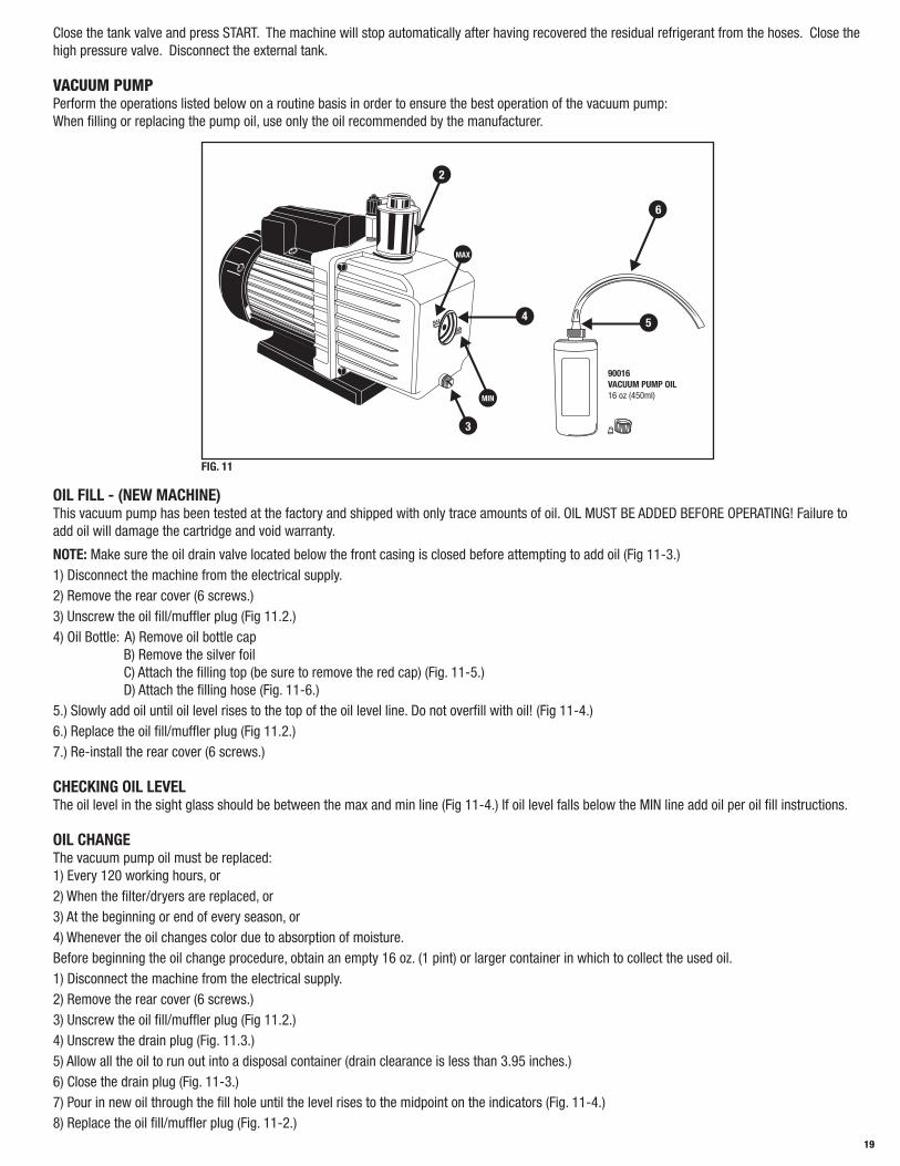
VACUUM PUMPPerform the operations listed below on a routine basis in order to ensure the best operation of the vacuum pump:When filling or replacing the pump oil, use only the oil recommended by the manufacturer.
MAX
MIN
2
3
MIN
MAX
4 5
6
90016 VACUUM PUMP OIL16 oz (450ml)
FIG. 11
OIL FILL - (NEW MACHINE)This vacuum pump has been tested at the factory and shipped with only trace amounts of oil. OIL MUST BE ADDED BEFORE OPERATING! Failure to add oil will damage the cartridge and void warranty.
NOTE: Make sure the oil drain valve located below the front casing is closed before attempting to add oil (Fig 11-3.) 1) Disconnect the machine from the electrical supply.2) Remove the rear cover (6 screws.)3) Unscrew the oil fill/muffler plug (Fig 11.2.)4) Oil Bottle: A) Remove oil bottle cap B) Remove the silver foil C) Attach the filling top (be sure to remove the red cap) (Fig. 11-5.) D) Attach the filling hose (Fig. 11-6.) 5.) Slowly add oil until oil level rises to the top of the oil level line. Do not overfill with oil! (Fig 11-4.)6.) Replace the oil fill/muffler plug (Fig 11.2.)7.) Re-install the rear cover (6 screws.)
CHECKING OIL LEVELThe oil level in the sight glass should be between the max and min line (Fig 11-4.) If oil level falls below the MIN line add oil per oil fill instructions.
OIL CHANGEThe vacuum pump oil must be replaced: 1) Every 120 working hours, or2) When the filter/dryers are replaced, or3) At the beginning or end of every season, or4) Whenever the oil changes color due to absorption of moisture.Before beginning the oil change procedure, obtain an empty 16 oz. (1 pint) or larger container in which to collect the used oil. 1) Disconnect the machine from the electrical supply.2) Remove the rear cover (6 screws.)3) Unscrew the oil fill/muffler plug (Fig 11.2.)4) Unscrew the drain plug (Fig. 11.3.)5) Allow all the oil to run out into a disposal container (drain clearance is less than 3.95 inches.)6) Close the drain plug (Fig. 11-3.)7) Pour in new oil through the fill hole until the level rises to the midpoint on the indicators (Fig. 11-4.)8) Replace the oil fill/muffler plug (Fig. 11-2.)

20
9) Replace the rear plastic cover on the machine (6 screws.)
NOTE: When changing the vacuum pump oil, dispose of used oil as per federal, local and state regulations.
REPLACING THE DRYER FILTERSReplace the filters when the machine alerts you. Replace the filters only with Mastercool part numbers: 69788-FLTRPK. When changing the filters you will need a filter code. To obtain a filter code, please call Mastercool Inc. Technical Service at 888-825-6989.
LOCK OUT: If you are changing the filters because of the Second Service alarm (see page 9) and has locked out 69788, then a filter code will be needed to re-set 69788. Before changing the filters, call Mastercool Inc. Technical Service at 888-825-6989 to get the filter code.
NO LOCK OUT: If the filters are being changed at an unscheduled time, no filter code will be needed to continue operating 69788. Only when the machine reaches the pre-programmed recovery quantity of 132 lbs will it lock out. Once the machine is locked out, the filter code will be needed to re-set the 69788. (See LOCK OUT)
To change the filters, proceed as described below (refer to Fig. 12): 1) Disconnect the machine from the electrical supply. 2) Wear protective gloves and glasses.3) Remove the rear plastic cover from the machine (6 screws.)4) Close both of the valves on top of tank.5) Close the valve (Fig. 12-1) under the filter (Fig. 12-4.)6) Connect the low pressure quick-connect coupling to the male connector (Fig. 12-2) under the filter (Fig. 12-4.)7) Connect the machine to the electrical supply and turn the machine on.8) Put in the filter code. (Only if locked out) To put in the filter code, you will need to 1
23
45
use the down arrow key to move the cursor to the next character. To input a letter, FIG. 12
continue to press the same number with the corresponding letter until the desired letter appears. Once the entire code is showing on the screen, press the ENTER key. 9) Using Assisted Procedure, start a recovery operation (NOTE: the valve under the low pressure filter [Fig. 12-3] should be open).10) When oil draining is reached, immediately close the valve (Fig. 12-3) under the filter (Fig. 12-5) and turn the machine off.11) Disconnect the machine from the electrical supply.12) Disconnect the low pressure quick-connect coupling from the connector (Fig. 12-2) under the filter (Fig. 12-4).13) Replace the filters. IMPORTANT: The filter replacement must be performed as quickly as possible in order to avoid possible contamination by moisture in the ambient air.14) Open the valve (Fig. 12-1) under the filter (Fig. 12-4) and the valve (Fig. 12-3) under the filter (Fig. 12-5).15) Open both valves on top of the tank.16) Connect the machine to the electrical supply and turn the machine on. (Leave the rear cover off at this time)17) Press start when the machine displays “RECOVERY PROCEDURE INTERRUPTED, START: TO CONTINUE.”18) Press reset when the machine displays “ERROR SYSTEM EMPTY.”19) Tank charge about 1 lb (-500g) of refrigerant to charge the machine circuit.20) While the machine is recovering, use an electronic leak detector to check the seal on the connections that were opened to replace the filters. Re- tighten if necessary.21) Turn the machine off and replace the rear plastic cover on the machine. (6 screws)22) The machine is now ready for normal use.
FILLING THE NEW OIL CONTAINER It is good practice to fill the oil container whenever the oil level falls below 3.4 oz (100 cc) in order to guarantee that there will be sufficient oil for topping off during successive operations. Always refer to the information provided by the A/C system manufacturer for oil specifications (oil is not supplied.)
Lift the quick-connect coupling near the top of the container and remove the container complete with cap. Unscrew the cap and fill the container with the correct quantity of oil of suitable type and grade. Screw the cap back on and, lifting the quick-connect coupling as above, replace the container in its holder.
EMPTYING THE USED OIL CONTAINERThis operation must be performed whenever the oil level exceeds 6.7 oz (200 cc.) Procedure: Remove the container from its holder. Unscrew the container while holding the cap in place. Empty the used oil into a suitable container for used oils. Screw the container back in place while holding the cap in place. Carefully replace the container into its holder. (Dispose of used oil

21
as per your federal, local and state regulations.)
CHECKING THE SCALE RESPONSETurn the unit on and note the “REF AVAILABLE” reading. Hang the 500g test weight that was supplied with the machine from the hook under the scale. (Fig 13-7) The “REF AVAILABLE” should go up by 500g+/-28g, 1.10lb +/-.06lb or 18oz +/-1oz depending on what units the machine is set at. If the results of the test are not within these specifications, it is recommended that the scale be re-calibrated. The scale re-calibration should be done by a qualified Service Technician. The equipment necessary for scale re-calibration is not supplied with 69788.
6
4
3
5
2
17
FIG. 13
PURGING NON-CONDENSABLE GASESIf 69788 should become loaded with excessive tank pressure due to the accumulation of NCG (Non-Condensable Gases) it will be necessary that the operator purge the NCG manually. The operator will need to start the manual purge and the machine will automatically stop the purge when the proper pressure is reached. The operator can also stop the purge manually before the machine determines the proper pressure.
Select NEXT MENU, scroll down with the arrow, select AIR PURGE. The following screen will be displayed:
AIR PURGE
TANK PRESS XX PSI
TANK TEMP XX.X °F
PRESS: START
Press RESET to exit the manual purge.
NOTE: During the purging process some refrigerant will be released from the tank. Some loss of refrigerant is normal and unavoidable due to design limitations and the nature of R134a refrigerant.
SETTINGSLANGUAGESwitch the machine on. The MAIN MENU will appear after a few seconds:
AUTOMATIC PROCEDURE
ASSISTED PROCEDURE
<NEXT MENU>
Ref avail X,XX lb
Select NEXT MENU, Press ENTER:
LAST RECOVERED QTY
TANK CHARGING
AIR PURGE
<DATA AND CONFIGURAT.>
Select DATA AND CONFIGURAT., Press ENTER:
DATA
<CONFIGURATION>
SERVICES
PREVIOUS MENU
Select CONFIGURATION:

22
<LANGUAGE>
MEASURE UNITS
PREVIOUS MENU
Select LANGUAGE:
ENGLISH <-
ITALIANO
FRANCAIS
ESPANOL
NOTE: The current language is indicated by the symbol “<-“.
Use the ARROW keys to scroll the available languages. Confirm a language by pressing ENTER. The machine will reset and a few seconds later the MAIN MENU will appear in the chosen language.
UNITS OF MEASUREMENTSwitch the machine on. The MAIN MENU will appear after a few seconds:
AUTOMATIC PROCEDURE
ASSISTED PROCEDURE
<NEXT MENU>
Ref avail X,XX lb
Select NEXT MENU:
LAST RECOVERED QTY
TANK CHARGING
AIR PURGE
<DATA AND CONFIGURAT.>
Select DATA AND CONFIGURAT:
DATA
<CONFIGURATION>
SERVICES
PREVIOUS MENU
Select CONFIGURATION:
LANGUAGE
<MEASURE UNITS>
PREVIOUS MENU
Select MEASURE UNITS:
WEIGHT (lb)
PRESSURE psi
TEMPERATURE ˚F
EXIT
WEIGHTSelect WEIGHT:
WEIGHT (lb)
PRESSURE psi
TEMPERATURE ˚F
EXIT

23
Press ENTER to change from lb, oz, gr, Kg or lb:oz
WEIGHT (lb)
PRESSURE psi
TEMPERATURE ˚F
EXIT
Select another parameter or EXIT to go to the previous screen.
PRESSURESelect PRESSURE:
WEIGHT (lb)
PRESSURE psi
TEMPERATURE ˚F
EXIT
Press ENTER to change from bar to psi or from psi to bar.
WEIGHT (lb)
PRESSURE psi
TEMPERATURE ˚F
EXIT
Select another parameter or EXIT to go to the previous screen.
TEMPERATURESelect TEMPERATURE:
WEIGHT (lb)
PRESSURE psi
TEMPERATURE ˚F
EXIT
Press ENTER to change from °C to °F or from °F to °C.
WEIGHT (lb)
PRESSURE psi
TEMPERATURE ˚F
EXIT
Select another parameter or EXIT to go to the previous screen.
DATAThis menu shows all the data read by the machine.Switch the machine on. The MAIN MENU will appear after a few seconds:
AUTOMATIC PROCEDURE
ASSISTED PROCEDURE
<NEXT MENU>
Ref avail X,XX lb
Select NEXT MENU:
LAST RECOVERED QTY
TANK CHARGING
AIR PURGE
<DATA AND CONFIGURAT.>
Select DATA AND CONFIGURAT.:

24
<DATA>
CONFIGURATION
SERVICES
PREVIOUS MENU
Select DATA.The following screen will be displayed:
Ref avail XX.XX lb
Tank temper XX.X°F
Tank Press XX psi
ACp xx psi
NOTE: TP: xx psi will be flashing- Ref avail.: quantity of refrigerant available in the storage tank.- Tank temp.: temperature of the refrigerant storage tank.- Tp: pressure of refrigerant tank.- ACp: pressure in the external air conditioning system.
PASSWORD PROTECTIONA password can be used to prevent the machine from being used. Once a password is activated, it will be needed every time the operator makes an attempt to activate any command from the MAIN screen. To use the password feature,
AUTOMATIC PROCEDURE
ASSISTED PROCEDURE
<NEXT MENU>
Ref avail X,XX lb
Select NEXT MENU:
LAST RECOVERED QTY
TANK CHARGING
AIR PURGE
<DATA AND CONFIGURAT.>
Select DATA AND CONFIGURAT.:
DATA
CONFIGURATION
<SERVICES>
PREVIOUS MENU
Select SERVICES:
<PASSWORD>
COUNTERS
Select PASSWORD:
....
Put in your own 4 digit password and press enter.
CUSTOMIZING THE DBA (DATABASE ADVANCED)Select ASSISTED PROCEDURE. Scroll down with the (↓) DOWN arrow key until the vehicle brands in the DBA appear:

25
<ALFA ROMEO>
AUDI
BMW
CHRYSLER/JEEP
Press the (↑) UP arrow key:
TOYOTA
VOLKSWAGEN
VOLVO
<USER DEFINED>
Select the USER DEFINED option:
<ABCD EFGH>
HIJK MNOP
????
????
DATA ENTRYTo enter customized data, press START. The following screen will be displayed:
MODEL NAME:
......................
MODEL QUANTITY:
XXXX
Type in the vehicle model on the keyboard; press ENTER to confirm. Use the down arrow key to move the cursor to the next character.Type in the corresponding refrigerant quantity; press ENTER to confirm.
NOTE: Refrigerant quantity is in grams.
USETo use the customized data, scroll with the (↑↓) arrow keys to the desired vehicle model; press ENTER to confirm.
DELETIONTo delete custom data fields, scroll with the (↑↓) arrow keys to the desired vehicle model and press “0” (ZERO). An alarm signal will sound and the following screen will be displayed.
VEHICLE NAME
XXXX G
DELETE?
START: YES STOP: NO
Press START to delete the vehicle or STOP to exit without deleting the vehicle.
NOTE CONCERNING THE DATABASE: We have taken all due care in gathering and entering the information contained in the database. The database data must nevertheless be considered purely indicative; the manufacturer declines any and all responsibility for incorrect data.
DATABASE UPGRADEDatabase upgrades are available. Call 973-252-9119 and ask for details.
CONVERSION CHARTOunces (oz) to pounds (lbs): divide by 16
Pounds (lbs) to ounces (oz): multiply by 16
Ounces (oz) to grams (g): multiply by 28.4
Grams (g) to ounces (oz): divide by 28.4

26
If you have difficulty with a procedure please call Mastercool’s Technical Service at 973-252-9119
Pounds (lbs) to kilograms (kg): divide by 2.205
Kilograms (kg) to pounds (lbs): multiply by 2.205
Kilograms (kg) to ounces (oz): multiply by 35.27
Ounces (oz) to kilograms (kg): multiply by 0.0284
27
INTRODUCCIÓNEsta máquina ha sido aprobada por los laboratorios ETL en cumplimiento de la norma SAE J2788. Tratamos las cuestiones acerca de la contención segura y la gestión adecuada de refrigerantes. Su nueva máquina incorpora la última tecnología y presenta características de vanguardia que le ayudarán a realizar el mantenimiento de sistemas de acondicionamiento del aire con R134a y de refrigeración.
AVISO:La norma SAE J2788 ha realizado máquinas de reciclaje más complejas que los modelos anteriores conocidos por algunos usuarios. Algunos cambios evidentes para los usuarios de TODAS las máquinas de reciclaje nuevas son los siguientes.1. TIEMPO DE RECUPERACIÓN: El tiempo medio de recuperación es 30 minutos aproximadamente. Dicho tiempo cumple la norma SAE J2788 que determina que la máquina recupere por lo menos el 95% del refrigerante del sistema de acondicionamiento del aire y purifique el refrigerante en el 95% por lo menos. 2. TEMPERATURAS ALTAS: A medida que la temperatura ambiente se aproxima a los 100°F, algunos usuarios han experimentado una recuperación más larga. Este fenómeno es la respuesta natural del R134a cuando su temperatura aumenta. El R134a presenta dificultades para pasar del estado gaseoso al estado líquido con temperaturas elevadas. La transformación en líquido es necesaria para que la máquina complete el proceso de recuperación. El usuario notará el mismo efecto al CARGAR EL DEPÓSITO. 3. TEMPERATURAS BAJAS: A medida que la temperatura ambiente se aproxima a los 50°F, algunos usuarios han experimentado una recuperación más larga. Este fenómeno es la respuesta natural del R134a cuando su temperatura disminuye. El R134a presenta dificultades para pasar del estado líquido al estado de vapor con temperaturas bajas. La transformación en vapor es necesaria para que la máquina complete el proceso de destilación. El usuario notará el mismo efecto al CARGAR EL DEPÓSITO.
RESUMEN ACERCA DE LA SEGURIDADLa siguiente información acerca de la seguridad es dada como una guía para ayudarle a usar su nuevo sistema con la mayor seguridad. Todos los equipos que usan elementos químicos pueden resultar potencialmente peligrosos durante el uso si no conoce o no respeta las instrucciones de seguridad o para efectuar una gestión segura. Las siguientes instrucciones de seguridad proporcionan la información necesaria para el uso y el funcionamiento seguros al usuario. Le rogamos leer y guardar dichas instrucciones para usar siempre de forma segura su sistema de mantenimiento.
INFORMACIÓN SOBRE LA SEGURIDADTodos los trabajadores respetan sus herramientas de trabajo. Saben que las herramientas representan años de estudio y desarrollos constantemente mejorados. Los verdaderos trabajadores saben también que las herramientas son peligrosas si se hace un uso incorrecto o abusa de ellas. Lea, entienda y respete las siguientes instrucciones de seguridad para reducir el riesgo de incomodidad, enfermedades o incluso de muerte. Asimismo asegúrese de que toda persona que use este equipo a su vez entienda y respete también dichas instrucciones de seguridad.
LEA TODA LA INFORMACIÓN SOBRE LA SEGURIDAD DETENIDAMENTE antes de intentar instalar, poner en marcha o mantener este equipo. El incumplimiento de estas instrucciones puede provocar lesiones personales o daños en el equipo.
GUARDE LA SIGUIENTE INFORMACIÓN SOBRE LA SEGURIDAD PARA FUTURAS CONSULTAS. Las normas publicadas acerca de la seguridad están disponibles y enumeradas al final de esta sección bajo el nombre INFORMACIÓN ADICIONAL
SOBRE SEGURIDAD. El Código Eléctrico Nacional, los reglamentos de seguridad laboral y la legislación sobre la salud, los códigos industriales locales y los requisitos de inspección locales proporcionan también una idea para la instalación, el uso y el mantenimiento del equipo.
Los siguientes símbolos de aviso sobre seguridad identifican mensajes de seguridad importantes en este manual. Cuando vea uno de los símbolos mostrados, significa que puede sufrir lesiones personales, lea detenidamente el mensaje. No llene nunca el depósito hasta más del 80% de su capacidad porque ello impediría la creación de una cámara de expansión para absorber los aumentos de presión.
PELIGRO DE CHOQUE ELÉCTRICO• Desconecte el cable de alimentación del toma corriente antes de realizar cualquier operación de mantenimiento o limpieza para reducir el peligro de choque eléctrico. Apagar los mandos no reduce este peligro.
• No arranque la máquina con un cable de alimentación o un enchufe estropeados, sustituya el cable o el enchufe inmediatamente. Tire del enchufe y no del cable para desconectar el cable de alimentación para reducir el riesgo de estropear el cable y el enchufe.
No use una extension a no ser que sea absolutamente necesario. El uso de una extension inadecuada puede provocar riesgos de incendio, choque eléctrico y daños a los componentes. Si se ha de usar una extension, asegúrese de que:a. Las hembrillas del enchufe de la extension presenten el mismo tamaño, la misma forma y el mismo número que las varillas del enchufe del \ equipo de reciclaje.b. La extension este cableada adecuadamente y en buenas condiciones; yc. El tamaño del hilo sea lo suficientemente ancho para el largo del cable como se especifica a continuación:
28
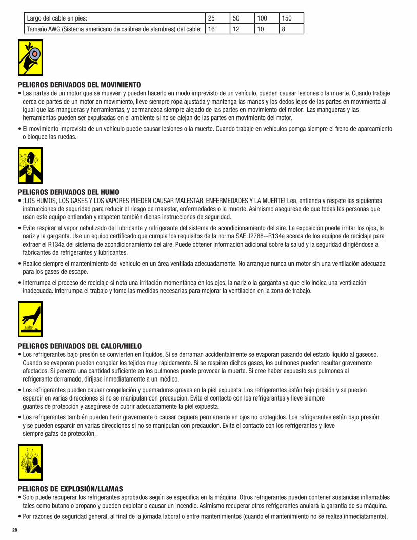
Largo del cable en pies: 25 50 100 150
Tamaño AWG (Sistema americano de calibres de alambres) del cable: 16 12 10 8
PELIGROS DERIVADOS DEL MOVIMIENTO• Las partes de un motor que se mueven y pueden hacerlo en modo imprevisto de un vehículo, pueden causar lesiones o la muerte. Cuando trabaje cerca de partes de un motor en movimiento, lleve siempre ropa ajustada y mantenga las manos y los dedos lejos de las partes en movimiento al igual que las mangueras y herramientas, y permanezca siempre alejado de las partes en movimiento del motor. Las mangueras y las herramientas pueden ser expulsadas en el ambiente si no se alejan de las partes en movimiento del motor.
• El movimiento imprevisto de un vehículo puede causar lesiones o la muerte. Cuando trabaje en vehículos pomga siempre el freno de aparcamiento o bloquee las ruedas.
PELIGROS DERIVADOS DEL HUMO• ¡LOS HUMOS, LOS GASES Y LOS VAPORES PUEDEN CAUSAR MALESTAR, ENFERMEDADES Y LA MUERTE! Lea, entienda y respete las siguientes instrucciones de seguridad para reducir el riesgo de malestar, enfermedades o la muerte. Asimismo asegúrese de que todas las personas que usan este equipo entiendan y respeten también dichas instrucciones de seguridad.
• Evite respirar el vapor nebulizado del lubricante y refrigerante del sistema de acondicionamiento del aire. La exposición puede irritar los ojos, la nariz y la garganta. Use un equipo certificado que cumpla los requisitos de la norma SAE J2788--R134a acerca de los equipos de reciclaje para extraer el R134a del sistema de acondicionamiento del aire. Puede obtener información adicional sobre la salud y la seguridad dirigiéndose a fabricantes de refrigerantes y lubricantes.
• Realice siempre el mantenimiento del vehículo en un área ventilada adecuadamente. No arranque nunca un motor sin una ventilación adecuada para los gases de escape.
• Interrumpa el proceso de reciclaje si nota una irritación momentánea en los ojos, la nariz o la garganta ya que ello indica una ventilación inadecuada. Interrumpa el trabajo y tome las medidas necesarias para mejorar la ventilación en la zona de trabajo.
PELIGROS DERIVADOS DEL CALOR/HIELO• Los refrigerantes bajo presión se convierten en líquidos. Si se derraman accidentalmente se evaporan pasando del estado líquido al gaseoso. Cuando se evaporan pueden congelar los tejidos muy rápidamente. Si se respiran dichos gases, los pulmones pueden resultar gravemente afectados. Si penetra una cantidad suficiente en los pulmones puede provocar la muerte. Si cree haber expuesto sus pulmones al refrigerante derramado, diríjase inmediatamente a un médico.
• Los refrigerantes pueden causar congelación y quemaduras graves en la piel expuesta. Los refrigerantes están bajo presión y se pueden esparcir en varias direcciones si no se manipulan con precaucion. Evite el contacto con los refrigerantes y lleve siempre guantes de protección y asegúrese de cubrir adecuadamente la piel expuesta.
• Los refrigerantes también pueden herir gravemente o causar ceguera permanente en ojos no protegidos. Los refrigerantes están bajo presión y se pueden esparcir en varias direcciones si no se manipulan con precaucion. Evite el contacto con los refrigerantes y lleve siempre gafas de protección.
PELIGROS DE EXPLOSIÓN/LLAMAS• Solo puede recuperar los refrigerantes aprobados según se especifica en la máquina. Otros refrigerantes pueden contener sustancias inflamables tales como butano o propano y pueden explotar o causar un incendio. Asimismo recuperar otros refrigerantes anulará la garantía de su máquina.
• Por razones de seguridad general, al final de la jornada laboral o entre mantenimientos (cuando el mantenimiento no se realiza inmediatamente),

29
verifique que todas las válvulas de las mangueras y de la máquina estén cerradas.
INFORMACIÓN ADICIONAL SOBRE SEGURIDAD Consulte las siguientes normas para obtener información adicional sobre la seguridad.Norma ANSI Z87.1 — SAFE PRACTICE FOR OCCUPATION AND EDUCATIONAL EYE AND FACE PROTECTION - Instituto de Normas Nacionales Norteamericano, 11 West 42nd St., Nueva York, NY 10036, Teléfono (212) 642-4900, Fax (212) 398-0023 - www.ansi.org
CUIDADO: Este equipo se ha de usar en lugares con una ventilación mecánica que proporcione por lo menos cuatro cambios de aire por hora o el equipo debe situarse a 18 pulgadas (457 mm) por lo menos sobre el pavimento u otro elemento equivalente.
CUIDADO: No realice una prueba de presión o una prueba de fuga al equipo de mantenimiento del R134a o a los sistemas de acondicionamiento del aire con aire comprimido. Algunas mezclas de aire y R134a resultan combustibles con presiones elevadas. Dichas mezclas pueden causar lesiones o daños en la propiedad. Puede obtener información adicional sobre la salud y seguridad de los fabricantes de refrigerantes.
ATENCIÓN: Los técnicos que usan este equipo han de estar certificados bajo la Sección 609 EPA (Environmental Protection Agency).
ADVERTENCIA: Puede producirse una contaminación del refrigerante en el contenedor del mismo o en el sistema de acondicionamiento del aire móvil en mantenimiento o en el contenedor del refrigerante. Antes del reciclaje, use un equipo idóneo tal como un identificador de refrigerante si es necesario.
NOTA: Use solamente un aceite refrigerante nuevo para sustituir la cantidad eliminada durante el proceso de reciclaje. El aceite usado se ha de eliminar según los requisitos federales, nacionales y locales.
El fabricante queda eximido de toda responsabilidad por los gastos adicionales derivados de la no eficiencia del producto entre los que se incluyen (aunque no son todos) pérdida de tiempo de trabajo, pérdida de refrigerante, contaminación cruzada del refrigerante y expedición no autorizada o cargos por manos de obra.
IMPORTANTE: Los sistemas con R134a presentan empalmes especiales (según las especificaciones SAE) para evitar la contaminación cruzada con los sistemas con R12. NO adapte su unidad para un refrigerante diferente - el sistema no funcionará.
INSPECCIONE PERIÓDICAMENTE Y REALICE EL MANTENIMIENTO DE LAS MANGUERAS DEL REFRIGERANTE Y JUNTAS PARA ASEGURAR QUE LAS MANGUERAS Y LAS JUNTAS IMPIDAN LA APORTACIÓN DE AIRE EXCESIVO A CAUSA DE FUGAS DURANTE EL PROCESO DE RECUPERACIÓN, LO CUAL AUMENTARÍA EL NIVEL DE GASES NO CONDENSABLES EN EL REFRIGERANTE RECUPERADO.
CERTIFICACIÓNTodos los técnicos que abren un circuito de refrigeración en sistemas de acondicionamiento del aire en autos han de estar certificados para realizar los procedimientos de recuperación y reciclaje del refrigerante en cumplimiento de la sección 609 de la enmienda a la Ley del Aire Limpio en ambientes cerrados (Florida) de 1990. Llame a MACS Worldwide al número (215) 631-7020 para obtener información sobre la certificación.
ACERCA DE ESTE MANUALEste manual incluye un RESUMEN SOBRE SEGURIDAD, PREPARACIÓN DE LA MÁQUINA PARA EL USO, procedimientos de FUNCIONAMIENTO e instrucciones de MANTENIMIENTO para su equipo de mantenimiento del aire acondicionado. Las personas que usen la máquina han de estar familiarizadas con TODA la información contenida en este manual (especialmente con el RESUMEN SOBRE SEGURIDAD) antes de usarla.
Antes de usar esta máquina por primera vez, cumpla todas las instrucciones de PREPARACIÓN PARA EL USO. Si no ha preparado correctamente su nueva máquina para realizar un mantenimiento, los datos de mantenimiento pueden ser incorrectos. Siga todos los procedimientos en el orden indicado para realizar un mantenimiento completo del aire acondicionado. Tómese el tiempo necesario para estudiar este manual antes de usar la máquina. Conserve este manual a su alcance para futuras consultas. Preste mucha atención al RESUMEN SOBRE SEGURIDAD y a todas las ADVERTENCIAS Y los CUIDADOS indicados en todo el manual.
ACERCA DE SU EQUIPO DE MANTENIMIENTO PARA LA RECUPERACIÓN/RECICLAJE DEL SISTEMA DEL AIRE ACONDICIONADO Su máquina incorpora una balanza electrónica de gran precisión para determinar los pesos de carga, etc. También podrá realizar otras funciones con la balanza electrónica como verá durante los procesos de funcionamiento. Puede seleccionar otros estándares o unidades métricas de medida. Su nueva máquina se ha diseñado específicamente para usar el R134a y funcionar según los objetivos del Protocolo de Montreal.
GARANTÍAEste producto está cubierto por una garantía contra defectos de materiales o fabricación durante un plazo de 1 (uno) año a contar a partir de la fecha de entrega. La garantía incluye la sustitución o reparación gratis de componentes defectuosos o de partes consideradas defectuosas por el fabricante. Indique siempre el número de serie de la máquina en las solicitudes de recambios. Esta garantía no cubre defectos derivados del deterioro normal, de una instalación incorrecta o inadecuada, o de fenómenos ajenos al uso y funcionamiento normales del producto.
NOTA: En relación con lo anterior, el Fabricante recuerda al Cliente que, según las leyes internacionales y nacionales y los reglamentos vigentes, los productos se expiden a riesgo exclusivo del Cliente y sin asegurar, a menos que se haya especificado lo contrario durante la fase de pedido. Por consiguiente, el Fabricante queda eximido de toda responsabilidad en relación con QUEJAS por los daños ocasionados durante la expedición, la carga y la descarga y el desembalaje.
El producto, para el que se requiere la reparación bajo garantía, se ha de expedir al fabricante bajo la responsabilidad exclusiva del cliente, que

30
correrá también con los gastos y será responsable de cualquier desperfecto exclusivamente. Se ha de usar siempre el embalaje original del fabricante y la balanza se ha de bloquear antes del envío según la configuración indicada en la página 30, para evitar daños durante el envío del producto para reparaciones.
El fabricante queda eximido de toda responsabilidad por los daños causados a vehículos en los que se realizan las operaciones de recuperación/reciclaje y recarga cuando dichos daños deriven de una manipulación inadecuada del operador o del incumplimiento de las reglas de seguridad básicas indicadas en el manual de instrucciones.
La garantía caducará automáticamente al final del plazo de 12 meses o cuando se produzcan uno de los siguientes casos: mantenimiento no realizado; aplicación de procedimientos de mantenimiento inadecuados; uso de lubricantes o de fluidos marcadores no idóneos; uso inepto o inapropiado; reparaciones realizadas por personal no autorizado o con recambios no originales; daños causados por impactos, incendios u otros eventos accidentales. Envíe la tarjeta de la garantía adjunta para activarla.
INFORMACIÓN GENERALLa información para la identificación de la máquina está impresa en la placa de datos situada en la parte trasera de la máquina (véase la Figura 1). Dimensiones totales de la máquina:
Altura: 41.7 inch Ancho: 19.7 inch Profundidad: 20.5 inch Peso: 200 lb
La máquina produce inevitablemente ruido como cualquier otro equipo con partes en movimiento. El sistema de construcción, los paneles y los suministros especiales adoptados por el Fabricante determinan durante el trabajo un nivel sonoro medio en la máquina inferior a 70 dB (A). NOTA: La máquina se ha diseñado para funcionar en un espacio cerrado exclusivamente.
FIG. 1
FIG. 2
PRINCIPIOS DE FUNCIONAMIENTOEn una serie individual de operaciones, la máquina permite recuperar y reciclar refrigerante sin riesgos de derrames en el medio ambiente y también permite eliminar la humedad y los depósitos contenidos en el aire del sistema de aire acondicionado. La máquina incorpora un evaporador / separador que elimina el aceite y otras impurezas contenidos en el refrigerante recuperado del sistema de aire acondicionado y los recoge en un contenedor específico. A continuación el fluido es alterado, reciclado y devuelto al depósito instalado en la máquina. La máquina permite también realizar pruebas de funcionamiento y fugas en el sistema del aire acondicionado.
MONTAJELa máquina se entrega totalmente ensamblada y probada. Consulte la Figura 3 para montar la manguera con el empalme rápido AZUL en el conector roscado macho indicado con el símbolo PRESIÓN BAJA AZUL y la manguera con el empalme rápido ROJO en el conector roscado macho indicado con el símbolo PRESIÓN ALTA ROJO.
Siga las indicaciones de la Figura 4 para desmontar la protección situada bajo la balanza del refrigerante de la forma siguiente (DESBLOQUEAR BALANZA):- Desenrosque la tuerca (Fig. 4-2.). - Desenrosque el tornillo (Fig. 4-1) de dos a cuatro vueltas (sin extraerlo de la máquina.)- Apriete la tuerca (Fig. 4-2.).
NOTA: Si ha de transportar el equipo; DEBE bloquear la balanza del depósito del refrigerante de la forma siguiente:
FIG. 3
ETIQUETA N.°/S
31
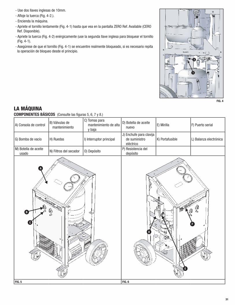
- Use dos llaves inglesas de 10mm.- Afloje la tuerca (Fig. 4-2.).- Encienda la máquina.- Apriete el tornillo lentamente (Fig. 4-1) hasta que vea en la pantalla ZERO Ref. Available (CERO Ref. Disponible).- Apriete la tuerca (Fig. 4-2) enérgicamente (use la segunda llave inglesa para bloquear el tornillo (Fig. 4-1).- Asegúrese de que el tornillo (Fig. 4-1) se encuentre realmente bloqueado, si es necesario repita la operación de bloqueo desde el principio.
6
4
3
5
2
1
7
FIG. 4
LA MÁQUINACOMPONENTES BÁSICOS (Consulte las figuras 5, 6, 7 y 8.)
A) Consola de controlB) Válvulas de mantenimiento
C) Tomas para mantenimiento de alta y baja
D) Botella de aceite nuevo
E) Mirilla F) Puerto serial
G) Bomba de vacío H) Ruedas I) Interruptor principalJ) Enchufe para clavija de suministro eléctrico
K) Portafusible L) Balanza electrónica
M) Botella de aceite usado
N) Filtros del secador O) DepósitoP) Resistencia del depósito
A
B
C F
E
D
FIG. 5 FIG. 6

32
I
K
J
L
H
G
FIG. 7
NM
P
O
FIG. 7 FIG. 8
MANDOS Y SISTEMA DE CONTROLConsulte la Figura 9
A1) Manómetro de alta presión A2) Manómetro de baja presión
A3) Teclado A4) Pantalla de LCD: 4 líneas, 20 caracteres
A1
A2A3
A4
FIG. 9
TECLADO SELECTOR DE FUNCIÓNSTOP: Presione para interrumpir la operación corriente -- recuperación - descarga de aceite - vacío/carga - descarga del aceite. Presione START para reanudar la operación desde el punto en el que se interrumpió. Al presionar STOP durante un estado de alarma, estado de error o un estado de final de operación se silencia la alarma sonora.
RESET: Presione para interrumpir el ciclo de vacío y la operación de carga. El procedimiento se reanudará desde el principio.
ENTER: Presione para confirmar el procedimiento o la operación que parpadea en la pantalla de LCD.
↓: Presione para desplazarse hacia abajo desde un procedimiento u operación a otro dentro de un menú.
↑: Presione para desplazarse hacia arriba desde un procedimiento u operación a otro dentro de un menú.
START: Presione para empezar el procedimiento o la operación mostrados en la pantalla.
NOTA: Los términos “Depósito” y “Botella” se usan para describir un envase del refrigerante.

33
ALARMASHIGH PRESSURE ALARM (ALARMA DE ALTA PRESIÓN): Un dispositivo acústico y una pantalla de LCD avisan cuando la presión del fluido en el circuito alcanza 290 psi (20 bar). La operación de recuperación se interrumpe automáticamente. Consulte la página 43, ELIMINAR gases no condensables.
FULL TANK ALARM (ALARMA DEPÓSITO LLENO): Un dispositivo acústico y una pantalla de LCD avisan cuando el depósito está lleno con más del 80% de su capacidad máxima; es decir, 24 lbs (10,8 kg.), la operación de RECUPERACIÓN se interrumpe automáticamente. Para cancelar esta alarma, cargue uno o más sistemas de aire condicionado antes de seguir recuperando refrigerante o use una balanza y un depósito D.O.T., cargue bastante refrigerante en el depósito D.O.T para disponer de 12 a 15 lbs de refrigerante aproximadamente. Este refrigerante puede recuperarse más tarde si 69788 necesita llenarse de nuevo con refrigerante (véase Alarma depósito vacío). NOTA: No intente cargar un nuevo depósito de refrigerante (depósito azul con válvula individual). Dichos depósitos no están aprobados D.O.T para el relleno y presentan solamente una válvula de control que permite la salida del refrigerante del depósito. Al tener solamente una válvula de control y CARECER de dispositivos de seguridad de presión, dichos depósitos no pueden rellenarse con 69788.NOTA: No transvase nunca refrigerantes en un cilindro o en un depósito salvo si está aprobado D.O.T para el relleno. La aprobación D.O.T. está indicada mediante la designación “DOT 4BA” o “DOT 4BW” impresa en el cuello del depósito (asa). ¡Si el depósito del refrigerante se llena excesivamente, puede explotar! El incumplimiento de estas advertencias puede causar lesiones personales o la muerte.
EMPTY TANK ALARM (ALARMA DEPÓSITO VACÍO): Un dispositivo acústico y una pantalla de LCD avisan cuando la cantidad del fluido refrigerante contenido en el depósito es demasiado baja. Entonces ha de rellenar la botella de 69788 de 12 a 15 lbs con refrigerante aproximadamente para eliminar la alarma.
SERVICE ALARM (ALARMA DE MANTENIMIENTO): Alarma de mantenimiento: La alarma de primer mantenimiento; cuando la cantidad total recuperada de refrigerante alcanza 114 lbs, un dispositivo acústico se oirá y en la pantalla de LCD aparecerá SERVICE ALARM. Presione STOP para cancelar la alarma. Después de eliminar la primera alarma, ha de comprar filtros para disponer de ellos cuando 69788 requiera el cambio de los filtros. La alarma de segundo mantenimiento; cuando la cantidad total recuperada de refrigerante alcanza 132 lbs, un dispositivo acústico se oirá y en la pantalla de LCD aparecerá ENTER FILTER CODE (INTRODUCIR CÓDIGO FILTRO). Aparecerán también 10 puntos en la parte inferior de la pantalla. Los filtros se han de sustituir para desactivar la alarma (véase la página 42).NOTA: Es recomendable cambiar el aceite de la bomba de vacío cuando se cambian los filtros. (véase la página 42, Bomba de vacío)
LOW REFRIGERANT ALARM (ALARMA DE REFRIGERANTE BAJO): Un dispositivo acústico y la pantalla de LCD avisan cuando la cantidad de carga excede la cantidad de refrigerante disponible. La cantidad mínima de refrigerante es 4,50 lbs. Si el gas disponible menos la cantidad de carga es inferior a 4,5 lbs, 69788 interrumpe la carga y avisa al operador que hay poco refrigerante. Entonces ha de cargar el depósito 69788 de 12 a 15 lbs con refrigerante aproximadamente para realizar una carga. Por ejemplo, si el gas disponible es 9,50 lbs y la cantidad de carga es 1,80 lbs, entonces 9,50 lbs menos 1,80 lbs es igual a 7,70 lbs. 7,70 lbs es mayor que 4.50 lbs por lo que 69788 realizará una carga. Si el gas disponible es 5,90 lbs y la cantidad de carga es 1,80 lbs, entonces 5,90 lbs menos 1,80 lbs es igual a 4,10 lbs. 4,10 lbs es menor que 4,50 lbs, por lo que 69788 no cargará e informará al operador que no hay suficiente refrigerante disponible.
OPERACIONES PRELIMINARESControle que el interruptor principal (Fig. 7-I, página 32) se encuentre situado en 0. Controle que todas las válvulas de la máquina estén cerradas. Conecte la máquina al suministro eléctrico y enciéndala. Controle que el indicador del nivel de aceite de la bomba de vacío aparezca por lo menos medio lleno. Si el nivel es inferior, agregue aceite siguiendo las indicaciones de la sección MANTENIMIENTO ORDINARIO (página 39). Controle que el nuevo depósito del aceite (Fig. 6-D, página 31) contenga por lo menos 3,4 oz. (100 cc) del aceite recomendado por el fabricante del sistema de aire acondicionado del vehículo. Controle que el nivel del aceite en el depósito del aceite usado (Fig. 8-M, página 32) sea inferior a 6,7 oz. (200 cc.). Controle la pantalla de la máquina para asegurarse de que hay al menos 9 lbs (4,08 kg) de refrigerante en el depósito. De lo contrario, rellene el depósito de la máquina a bordo mediante un depósito externo de refrigerante adecuado, siguiendo los procedimientos descritos en la sección de MANTENIMIENTO ORDINARIO (página 39).
ADVERTENCIA:NO INTERRUMPA EL PROCESO DE RECUPERACIÓN. Interrumpir el proceso de recuperación causa daños irreversibles al compresor y también a otros componentes. Provoca también que la máquina se llene con un refrigerante líquido no procesado, lo cual inhabilitará la máquina para usos futuros. Los daños causados por INTERRUMPIR EL PROCESO DE RECUPERACIÓN pueden anular la garantía.
PROCEDIMIENTO AUTOMÁTICOEn el modo automático, las operaciones de recuperación y reciclaje, descarga del aceite y de vacío se realizan en una secuencia automática. Se puede agregar más aceite nuevo únicamente cuando la bomba de vacío se haya detenido. Entonces la máquina se pone en carga de refrigerante automática cuando el botón de start está presionado. Conecte las mangueras al sistema de aire acondicionado mediante los empalmes rápidos, recuerde que la manguera AZUL se ha de conectar en el lado de baja presión y la ROJA en el de alta presión. Abra las válvulas de empalme rápido. Si el sistema del aire acondicionado está equipado con un empalme rápido individual para alta y baja presión, realice la conexión y abra solamente el empalme rápido y la manguera correspondientes.
NOTA: Si el procedimiento automático se selecciona cuando el sistema del aire acondicionado está vacío, la máquina iniciará la fase de vacío. Cuando trabaje con sistemas de aire acondicionado con un solo empalme para la alta presión (ROJO), considere una cantidad de carga adicional de

34
unas 3 oz (100 g) respecto de la cantidad requerida ya que es imposible recuperar el refrigerante residual de las mangueras después de la carga.
Controle que las válvulas de mantenimiento alta y baja en el panel frontal 69788 estén cerradas. Arranque el motor del vehículo y encienda el acondicionador del aire (solamente si el aire acondicionado del vehículo funciona. Si el aire acondicionado no funciona no realice este paso). Deje ambos arrancados durante un tiempo de 5 a 10 minutos con el ventilador del compartimento del pasajero a la máxima velocidad. Apague el motor del vehículo.
La máquina está equipada con una pantalla de LCD de 4 líneas, máximo 20 caracteres por línea. En el menú presione la flecha hacia abajo hasta que vea la línea seleccionada parpadear; en este manual aparece entre comillas. Presione ENTER para seleccionar el procedimiento automático cuando “Automatic Procedure” (Procedimiento automático) parpadea en la pantalla.
<USO AUTOMATICO>
→ENTER→
<VACIO XX MIN>
PROCEDIMIENTO MANUAL CARGA X :XX lb
CONTINUAR MENU
Ref avai l X :XX lb
Introduzca el tiempo deseado para configurar el tiempo de vacío. Presione Enter para aceptar el valor de tiempo existente. La máquina automáticamente realizará un test de 2 minutos de VACUUM LEAK (FUGA VACÍO) cuando el valor del tiempo es de 11 minutos o superior. La prueba de FUGA VACÍO empezará después de 10 minutos del ciclo de vacío. Si se detecta una fuga la máquina notificará al operador que se ha detectado una fuga e interrumpirá el ciclo de vacío. Si no se detectan fugas, la máquina seguirá realizando el ciclo de vacío durante el tiempo restante.
<VACIO XX MIN>
→2→0→
<VACIO 20 MIN>
CARGA X :XX lb CARGA X :XX lb
Después de confirmar el tiempo de vacío, el mensaje de “charging x: xx lb” parpadeará. Determine la cantidad de refrigerante que va a cargar, para ello use uno de los dos procedimientos siguientes:
1. Determine la cantidad de refrigerante requerido para el sistema de aire acondicionado que va a cargar. A continuación se facilitan ejemplos para cada conjunto de unidades. Lb, la pantalla presenta 4 dígitos, dos dígitos un punto decimal y otros dos dígitos. El cursor se mueve de izquierda a derecha. Si la carga deseada es 1,75 lbs, introducirá 0 1 7 5. Oz, la pantalla presenta 3 dígitos. El cursor se mueve de derecha a izquierda. Si la carga deseada es 36 oz, introducirá 0 3 6. Gr, la pantalla presenta 5 dígitos. El cursor se mueve de derecha a izquierda. Si la carga deseada es 980 gramos, introducirá 9 8 0. kg, la pantalla presenta 3 dígitos, dos dígitos un decimal y otro dígito. El cursor se mueve de derecha a izquierda. Si la carga deseada es 1.5 Kg entonces introducirá 1 5. Lb, oz la pantalla presenta 4 dígitos, dos dígitos dos puntos y otros dos dígitos. El cursor se mueve de izquierda a derecha. Si la carga deseada es 1 lb 7 oz, introducirá 0 1 0 7.
VACIO XX MIN
0→1→0→7→ENTER→
ABRA LAS VÁLVULAS DE ALTA Y BAJA Y PRESIONE START<CARGA XX:XX lb>
NOTA: Cuando trabaje con sistemas de aire acondicionado con un solo empalme para la alta presión (ROJO), considere una cantidad de carga adicional de unos 3 oz (19 lb o 85g) respecto de la cantidad requerida ya que es imposible en este caso recuperar el refrigerante residual de las mangueras después de la carga.
NOTA: En la mayoría de los casos, la cantidad de refrigerante cargada en el sistema del aire acondicionado se indica en una placa de datos dentro del compartimento del motor del vehículo. Si no conoce la cantidad correcta, consulte los manuales correspondientes.
2. Este modelo está equipado con capacidades de refrigerantes guardadas en su base de datos. Presione la tecla 4, aparecerá lo siguiente en la pantalla:
<ALFA ROMEO>
AUDI
BMW
CHRYSLER/JEEP
Use las teclas flechas (↓↑) para seleccionar la marca del vehículo requerido y presione ENTER para confirmar. En la pantalla aparecerán los varios modelos (por ejemplo, si la marca elegida era la FORD):

35
<COUGAR>
ESCORT
ESCORT D
FIESTA
Use las teclas flechas (↓↑) para seleccionar el modelo requerido y presione ENTER para confirmar.
VACÍO 20 MIN
<LLENADO w:yz lb>
“w:yz” se refieren a la cantidad de refrigerante para el vehículo seleccionado. La máquina estará lista para agregar la cantidad correcta de refrigerante. Presione la tecla ENTER para confirmar.
Abra las válvulas de mantenimiento alta y baja en la máquina y presione la tecla START para empezar la fase de recuperación/reciclaje, que se indicará en la pantalla de LCD como “RECOVERY/RECYCLING” (RECUPERACIÓN/RECICLAJE). Durante esta fase, la pantalla de LCD mostrará la cantidad de refrigerante recuperado. Cuando acabe la recuperación, la máquina se parará y descargará automáticamente el aceite usado del sistema de aire acondicionado (si lo había durante la recuperación). La operación de vaciado del aceite dura entre 6 y 14 minutos dependiendo de la temperatura ambiente y de la cantidad de refrigerante recuperado. Durante la operación de vaciado del aceite aparecerá la siguiente pantalla.
RECOVERY PAUSED = RECUPERACION PAUSADA
OIL DRAINING = DRENANDO ACEITE
AGUARDAR = ESPERAR
TIME: 6 MIN
Si queda refrigerante residual en el sistema de aire acondicionado, como así lo indica un aumento de temperatura durante la fase de vaciado del aceite, la recuperación se reanudará automáticamente.
NOTA: Interrumpir la fase de recuperación antes de vaciar el aceite puede estropear el compresor de la máquina de recuperación/reciclaje.
Al final del vaciado, la máquina controla la presencia de aire en el depósito y, si es necesario, purga los gases no condensables. La alarma sonará continuamente y en la pantalla aparece el mensaje:
PURGA DE AIRE
Ref . recuperación x :xx lb
Tp: xx psi T:xx ˚F
La máquina de recuperación/reciclaje purgará automáticamente los gases no condensables (NCGS) cuando se detecte un exceso de ellos al final de la recuperación. Deje que la unidad complete este procedimiento, para eliminar la posibilidad de cargar gases no condensables en el sistema de aire acondicionado.
La máquina automáticamente activará la fase de vacío durante el tiempo predefinido. Al final de la fase de vacío, la máquina se para, emite un beep y muestra:
INYECCIÓN DE ACEITE
PRESIONE START PARA CONTINUAR
Entonces 69788-A se pone en pausa y permite al operador inyectar el aceite . Si se necesita aceite, abra la válvula del aceite NUEVO y agregue la cantidad necesaria. Después de finalizar la operación anterior, cierre la válvula del aceite NUEVO y presione START para cargar la cantidad de refrigerante definida anteriormente. Si no se ha de inyectar aceite, presione START.
NOTA: Es sumamente importante acordarse de CERRAR la válvula del aceite nuevo antes de presionar el botón de START. Si dicha válvula no se cierra, el refrigerante se presuriza excesivamente en la botella del NUEVO aceite y rompe dicha botella.
NOTA: El uso de un aceite PAG o de un marcador en vehículos híbridos puede estropear el compresor. Use solamente aceite adecuado con otro dispositivo para inyectar el aceite.
NOTA: La carga puede no completarse a causa del equilibrio de presión entre el depósito de almacenaje del refrigerante interno y el sistema del aire acondicionado. Si esto ocurre, cierre la válvula de alta presión (dejando el lado de baja presión abierto), arranque el vehículo y encienda el sistema del aire acondicionado. La unidad está equipada con una resistencia en el depósito para limitar este hecho. Cuando acaba la carga, la máquina muestra los siguientes cuadros de diálogo:
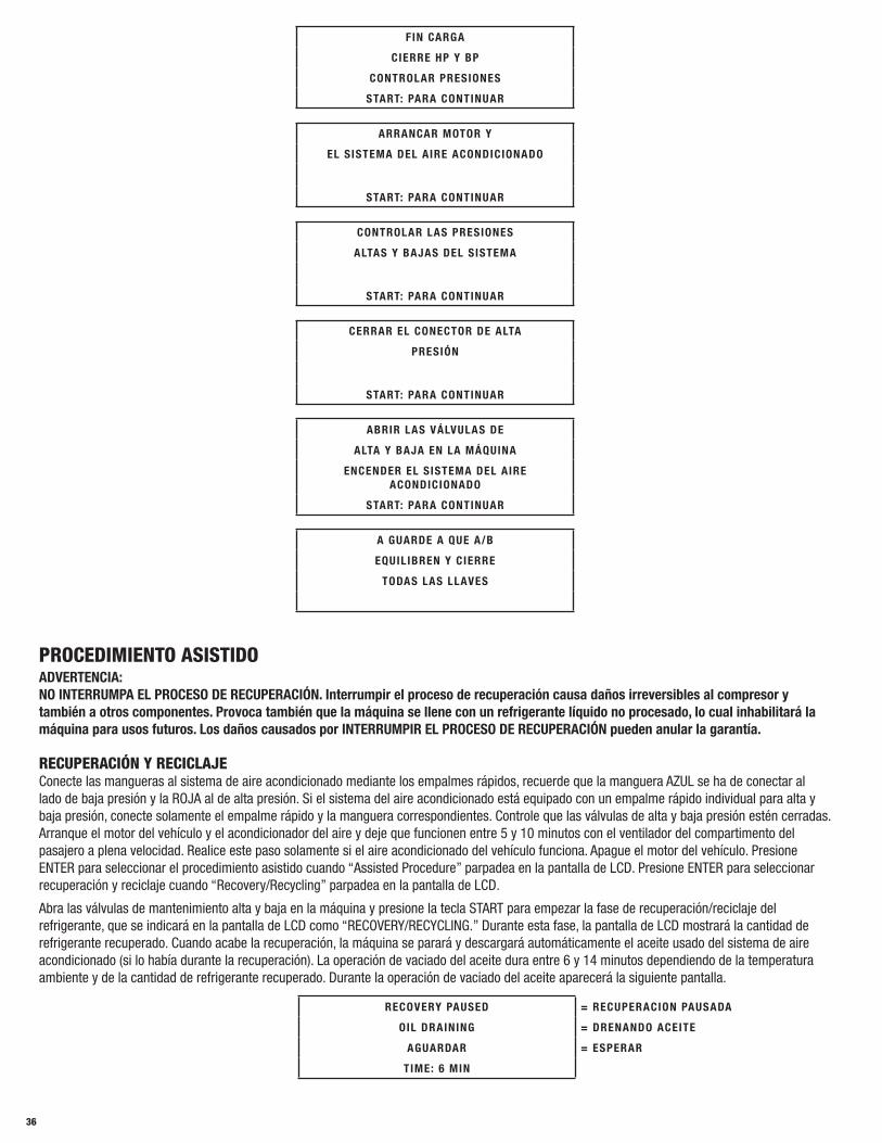
36
FIN CARGA
CIERRE HP Y BP
CONTROLAR PRESIONES
START: PARA CONTINUAR
ARRANCAR MOTOR Y
EL SISTEMA DEL AIRE ACONDICIONADO
START: PARA CONTINUAR
CONTROLAR LAS PRESIONES
ALTAS Y BAJAS DEL SISTEMA
START: PARA CONTINUAR
CERRAR EL CONECTOR DE ALTA
PRESIÓN
START: PARA CONTINUAR
ABRIR LAS VÁLVULAS DE
ALTA Y BAJA EN LA MÁQUINA
ENCENDER EL SISTEMA DEL AIRE ACONDICIONADO
START: PARA CONTINUAR
A GUARDE A QUE A/B
EQUILIBREN Y CIERRE
TODAS LAS LLAVES
PROCEDIMIENTO ASISTIDOADVERTENCIA: NO INTERRUMPA EL PROCESO DE RECUPERACIÓN. Interrumpir el proceso de recuperación causa daños irreversibles al compresor y también a otros componentes. Provoca también que la máquina se llene con un refrigerante líquido no procesado, lo cual inhabilitará la máquina para usos futuros. Los daños causados por INTERRUMPIR EL PROCESO DE RECUPERACIÓN pueden anular la garantía.
RECUPERACIÓN Y RECICLAJEConecte las mangueras al sistema de aire acondicionado mediante los empalmes rápidos, recuerde que la manguera AZUL se ha de conectar al lado de baja presión y la ROJA al de alta presión. Si el sistema del aire acondicionado está equipado con un empalme rápido individual para alta y baja presión, conecte solamente el empalme rápido y la manguera correspondientes. Controle que las válvulas de alta y baja presión estén cerradas. Arranque el motor del vehículo y el acondicionador del aire y deje que funcionen entre 5 y 10 minutos con el ventilador del compartimento del pasajero a plena velocidad. Realice este paso solamente si el aire acondicionado del vehículo funciona. Apague el motor del vehículo. Presione ENTER para seleccionar el procedimiento asistido cuando “Assisted Procedure” parpadea en la pantalla de LCD. Presione ENTER para seleccionar recuperación y reciclaje cuando “Recovery/Recycling” parpadea en la pantalla de LCD.
Abra las válvulas de mantenimiento alta y baja en la máquina y presione la tecla START para empezar la fase de recuperación/reciclaje del refrigerante, que se indicará en la pantalla de LCD como “RECOVERY/RECYCLING.” Durante esta fase, la pantalla de LCD mostrará la cantidad de refrigerante recuperado. Cuando acabe la recuperación, la máquina se parará y descargará automáticamente el aceite usado del sistema de aire acondicionado (si lo había durante la recuperación). La operación de vaciado del aceite dura entre 6 y 14 minutos dependiendo de la temperatura ambiente y de la cantidad de refrigerante recuperado. Durante la operación de vaciado del aceite aparecerá la siguiente pantalla.
RECOVERY PAUSED = RECUPERACION PAUSADA
OIL DRAINING = DRENANDO ACEITE
AGUARDAR = ESPERAR
TIME: 6 MIN
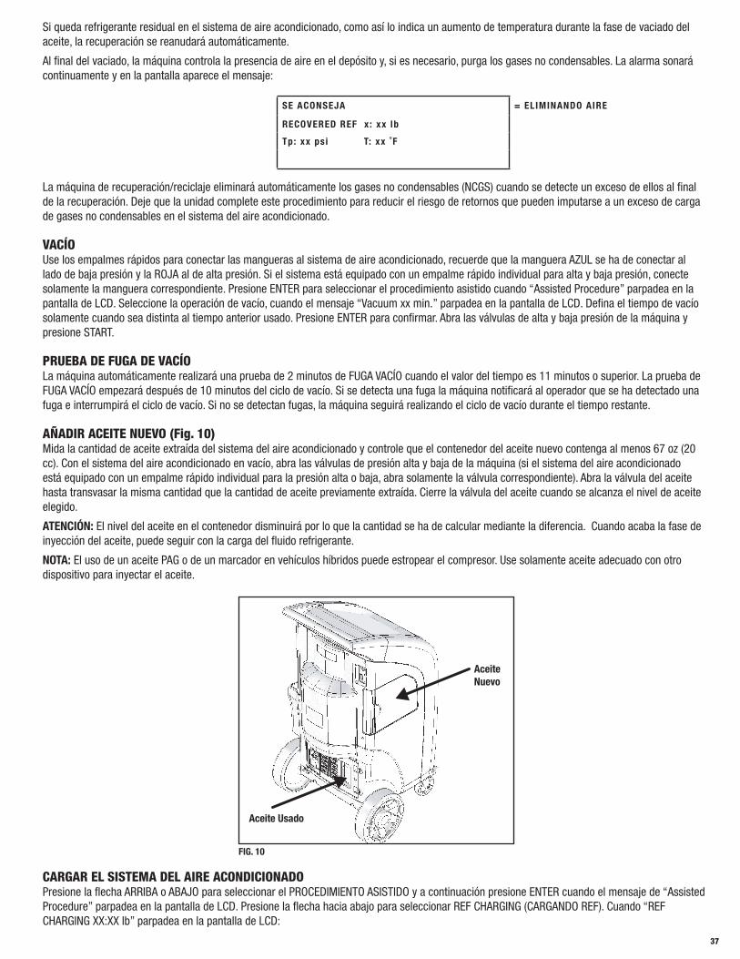
37
Si queda refrigerante residual en el sistema de aire acondicionado, como así lo indica un aumento de temperatura durante la fase de vaciado del aceite, la recuperación se reanudará automáticamente.
Al final del vaciado, la máquina controla la presencia de aire en el depósito y, si es necesario, purga los gases no condensables. La alarma sonará continuamente y en la pantalla aparece el mensaje:
SE ACONSEJA = ELIMINANDO AIRE
RECOVERED REF x : xx lb
Tp: xx psi T: xx ˚F
La máquina de recuperación/reciclaje eliminará automáticamente los gases no condensables (NCGS) cuando se detecte un exceso de ellos al final de la recuperación. Deje que la unidad complete este procedimiento para reducir el riesgo de retornos que pueden imputarse a un exceso de carga de gases no condensables en el sistema del aire acondicionado.
VACÍO Use los empalmes rápidos para conectar las mangueras al sistema de aire acondicionado, recuerde que la manguera AZUL se ha de conectar al lado de baja presión y la ROJA al de alta presión. Si el sistema está equipado con un empalme rápido individual para alta y baja presión, conecte solamente la manguera correspondiente. Presione ENTER para seleccionar el procedimiento asistido cuando “Assisted Procedure” parpadea en la pantalla de LCD. Seleccione la operación de vacío, cuando el mensaje “Vacuum xx min.” parpadea en la pantalla de LCD. Defina el tiempo de vacío solamente cuando sea distinta al tiempo anterior usado. Presione ENTER para confirmar. Abra las válvulas de alta y baja presión de la máquina y presione START.
PRUEBA DE FUGA DE VACÍO La máquina automáticamente realizará una prueba de 2 minutos de FUGA VACÍO cuando el valor del tiempo es 11 minutos o superior. La prueba de FUGA VACÍO empezará después de 10 minutos del ciclo de vacío. Si se detecta una fuga la máquina notificará al operador que se ha detectado una fuga e interrumpirá el ciclo de vacío. Si no se detectan fugas, la máquina seguirá realizando el ciclo de vacío durante el tiempo restante.
AÑADIR ACEITE NUEVO (Fig. 10) Mida la cantidad de aceite extraída del sistema del aire acondicionado y controle que el contenedor del aceite nuevo contenga al menos 67 oz (20 cc). Con el sistema del aire acondicionado en vacío, abra las válvulas de presión alta y baja de la máquina (si el sistema del aire acondicionado está equipado con un empalme rápido individual para la presión alta o baja, abra solamente la válvula correspondiente). Abra la válvula del aceite hasta transvasar la misma cantidad que la cantidad de aceite previamente extraída. Cierre la válvula del aceite cuando se alcanza el nivel de aceite elegido.
ATENCIÓN: El nivel del aceite en el contenedor disminuirá por lo que la cantidad se ha de calcular mediante la diferencia. Cuando acaba la fase de inyección del aceite, puede seguir con la carga del fluido refrigerante.
NOTA: El uso de un aceite PAG o de un marcador en vehículos híbridos puede estropear el compresor. Use solamente aceite adecuado con otro dispositivo para inyectar el aceite.
Aceite Nuevo
Aceite Usado
FIG. 10
CARGAR EL SISTEMA DEL AIRE ACONDICIONADO Presione la flecha ARRIBA o ABAJO para seleccionar el PROCEDIMIENTO ASISTIDO y a continuación presione ENTER cuando el mensaje de “Assisted Procedure” parpadea en la pantalla de LCD. Presione la flecha hacia abajo para seleccionar REF CHARGING (CARGANDO REF). Cuando “REF CHARGING XX:XX lb” parpadea en la pantalla de LCD:

38
Determine la cantidad de refrigerante requerido para el sistema de aire acondicionado que va a cargar usando uno de los dos procedimientos siguientes.
1. Funcionamiento manual: Determine la cantidad para la carga. A continuación se facilitan ejemplos para cada conjunto de unidades. Lb, la pantalla presenta 4 dígitos, dos dígitos un punto decimal y otros dos dígitos. El cursor se mueve de izquierda a derecha. Si la carga deseada es 1,75 lbs, introducirá 0 1 7 5. Oz, la pantalla presenta 3 dígitos. El cursor se mueve de derecha a izquierda. Si la carga deseada es 36 oz, introducirá 0 3 6. Gr, la pantalla presenta 5 dígitos. El cursor se mueve de derecha a izquierda. Si la carga deseada es 980 gramos, introducirá 9 8 0. kg, la pantalla presenta 3 dígitos, dos dígitos un decimal y un dígito. El cursor se mueve de derecha a izquierda. Si la carga deseada es 1.5 Kg entonces introducirá 1 5. Lb, oz la pantalla presenta 4 dígitos, dos dígitos dos puntos y otros dos dígitos. El cursor se mueve de izquierda a derecha. Si la carga deseada es 1 lb 7 oz, introducirá 0 1 0 7.
NOTA: Cuando trabaje con sistemas de aire acondicionado con un solo empalme para la alta presión (ROJO), considere una cantidad de carga adicional de unos 3 oz (19 lb o 85 g) respecto de la cantidad requerida ya que es imposible en este caso recuperar el refrigerante residual de las mangueras después de la carga.
2. Este modelo está equipado con algunas capacidades de refrigerantes guardadas en su base de datos. Presione la tecla “i”, aparecerá lo siguiente en la pantalla:
<ALFA ROMEO>
AUDI
BMW
CHRYSLER/JEEP
Use las teclas flechas (↓↑) para seleccionar la marca del vehículo requerido y presione ENTER para confirmar. En la pantalla aparecerán los difer-entes modelos (por ejemplo, si la marca elegida era la FORD)
<COUGAR>
ESCORT
ESCORT D
FIESTA
Use las teclas flechas (↓↑) para seleccionar el modelo requerido y presione ENTER para confirmar. Los siguientes datos aparecerán en la pantalla:
VACÍO 20 MIN
<LLENADO w:yz lb>
“w:yz” se refieren a la cantidad para el vehículo seleccionado. La máquina estará lista para agregar la cantidad correcta de refrigerante. Presione la tecla ENTER para confirmar.
Abra las válvulas de mantenimiento de alta y baja en la máquina y presione la tecla START (si el sistema del aire acondicionado presente solamente un empalme de alta o baja presión, abra solamente la válvula correspondiente en la máquina).
NOTA: La carga puede no completarse a causa del equilibrio de presión entre el depósito interno y el sistema del aire acondicionado. Si esto ocurre, cierre la válvula en el empalme rápido de alta presión (dejando el lado de baja presión abierto), arranque el vehículo y encienda el sistema del aire acondicionado. La unidad está equipada con una resistencia en el depósito para limitar este hecho. Cuando acaba la carga, la máquina muestra los siguientes cuadros de diálogo:
FIN CARGA
CIERRE HP Y BP
CONTROLAR PRESIONES
START: PARA CONTINUAR
ARRANCAR MOTOR ENCENDER
EL SISTEMA DEL AIRE
ACONDICIONADO
START: PARA CONTINUAR
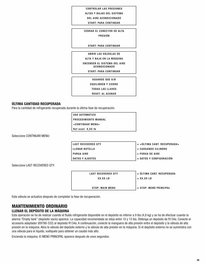
39
CONTROLAR LAS PRESIONES
ALTAS Y BAJAS DEL SISTEMA
DEL AIRE ACONDICIONADO
START: PARA CONTINUAR
CERRAR EL CONECTOR DE ALTA
PRESIÓN
START: PARA CONTINUAR
ABRIR LAS VÁLVULAS DE
ALTA Y BAJA EN LA MÁQUINA
ENCENDER EL SISTEMA DEL AIRE ACONDICIONADO
START: PARA CONTINUAR
AGUARDE QUE A/B
EQUILIBREN Y CIERRE
TODAS LAS LLAVES
RESET: AL ACABAR
ÚLTIMA CANTIDAD RECUPERADA Para la cantidad de refrigerante recuperada durante la última fase de recuperación.
USO AUTOMATICO
PROCEDIMIENTO MANUAL
<CONTINUAR MENU>
Ref avai l X ,XX lb
Seleccione CONTINUAR MENU:
LAST RECOVERED QTY = <ÚLTIMA CANT. RECUPERADA>
LLENAR BOTELLA = CARGANDO CILINDRO
PURGA AIRE = PURGA DE AIRE
DATOS Y AJUSTES = DATOS Y CONFIGURACIÓN
Seleccione LAST RECOVERED QTY:
LAST RECOVERED QTY = ÚLTIMA CANT. RECUPERADA
XX.XX LB = XX.XX LB
STOP: MAIN MENU = STOP: MENÚ PRINCIPAL
Esta válvula se actualiza después de completar la fase de recuperación.
MANTENIMIENTO ORDINARIOLLENAR EL DEPÓSITO DE LA MÁQUINAEsta operación se ha de realizar cuando el fluido refrigerante disponible en el depósito es inferior a 9 lbs (4,8 kg) y se ha de efectuar cuando la alarma “Empty tank” (depósito vacío) aparece. La capacidad recomendada se sitúa entre 10 y 15 lbs. Obtenga un depósito de R134a. Conecte el accesorio adaptador (69788-332) al depósito R134a. A continuación, conecte la manguera de alta presión entre el depósito y la válvula de alta presión en la máquina. Abra la válvula del depósito externo y la válvula de alta presión en la máquina. Si el depósito externo no se suministra con una válvula para el líquido, vuélquelo para obtener un caudal más alto.
Encienda la máquina. El MENÚ PRINCIPAL aparece después de unos segundos:

40
USO AUTOMATICO
PROCEDIMIENTO MANUAL
<CONTINUAR MENU>
Ref avai l X ,XX lb
Seleccione CONTINUAR MENU:
LAST RECOVERED = ÚLTIMA CANT. RECUPERADA
<LLENAR BOTELLA> = <CARGANDO CILINDRO>
PURGA AIRE = PURGA DE AIRE
DATOS Y AJUSTES = DATOS Y CONFIGURACIÓN
Seleccione LLENAR BOTELLA:
LLENAR BOTELLA = CARGANDO CILINDRO
CANTIDAD xx lb = Set amount xx lb
Min: x Max: xx lb = Min: x Max: xx lb
PRESIONE: START = PRESIONE: START
Defina la cantidad de refrigerante y presione START para confirmar: Siga las instrucciones de la pantalla.
USE LA MANGUERA DE ALTA PRESIÓN PARA
CONECTAR EL DEPÓSITO EXTERNO Y
PRESIONE: START
Presione START de nuevo:Siga las instrucciones de la pantalla.
ABRA EL DEPÓSITO EXTERNO, ABRA LA
VÁLVULA DE ALTA PRESIÓN Y
PRESIONE: START
Presione START de nuevo:
LLENAR BOTELLA = CARGANDO CILINDRO
0 LB = 0 LB
ACP xx PSI = ACP xx PSI
TP xx PSI = TP xx PSI
Ahora se llenará el depósito de la máquina con la cantidad predefinida ± 1,1lb (= 500 g). Cuando se alcanza una cantidad menor que 1,11b (= 500 g), la máquina se para y aparece:
CARGANDO DEPÓSITO
CIERRE EL DEPÓSITO EXTERNO Y
PRESIONE: START
Cierre la válvula del depósito y presione START. La máquina se detiene automáticamente después de recuperar el refrigerante residual de las mangueras. Cierre la válvula de alta presión. Desconecte el depósito externo.
BOMBA DE VACÍORealice las operaciones enumeradas a continuación según una base de rutina para asegurar el mejor funcionamiento para la bomba de vacío: Cuando llene o cambie el aceite de la bomba, use solamente el aceite recomendado por el fabricante.
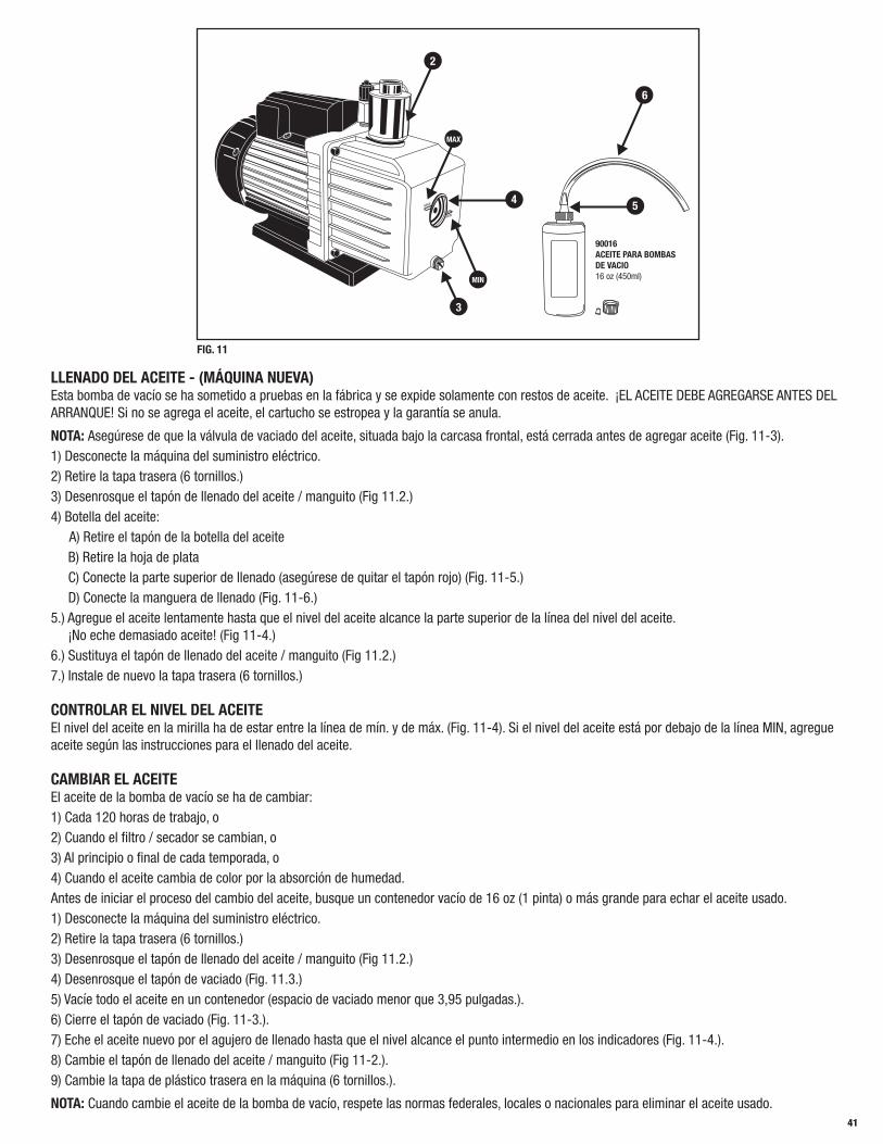
41
MAX
MIN
2
3
MIN
MAX
4 5
6
90016 ACEITE PARA BOMBAS DE VACIO16 oz (450ml)
FIG. 11
LLENADO DEL ACEITE - (MÁQUINA NUEVA)Esta bomba de vacío se ha sometido a pruebas en la fábrica y se expide solamente con restos de aceite. ¡EL ACEITE DEBE AGREGARSE ANTES DEL ARRANQUE! Si no se agrega el aceite, el cartucho se estropea y la garantía se anula.
NOTA: Asegúrese de que la válvula de vaciado del aceite, situada bajo la carcasa frontal, está cerrada antes de agregar aceite (Fig. 11-3). 1) Desconecte la máquina del suministro eléctrico.2) Retire la tapa trasera (6 tornillos.)3) Desenrosque el tapón de llenado del aceite / manguito (Fig 11.2.)4) Botella del aceite: A) Retire el tapón de la botella del aceite B) Retire la hoja de plata C) Conecte la parte superior de llenado (asegúrese de quitar el tapón rojo) (Fig. 11-5.) D) Conecte la manguera de llenado (Fig. 11-6.)5.) Agregue el aceite lentamente hasta que el nivel del aceite alcance la parte superior de la línea del nivel del aceite. ¡No eche demasiado aceite! (Fig 11-4.)6.) Sustituya el tapón de llenado del aceite / manguito (Fig 11.2.)7.) Instale de nuevo la tapa trasera (6 tornillos.)
CONTROLAR EL NIVEL DEL ACEITEEl nivel del aceite en la mirilla ha de estar entre la línea de mín. y de máx. (Fig. 11-4). Si el nivel del aceite está por debajo de la línea MIN, agregue aceite según las instrucciones para el llenado del aceite.
CAMBIAR EL ACEITEEl aceite de la bomba de vacío se ha de cambiar:1) Cada 120 horas de trabajo, o2) Cuando el filtro / secador se cambian, o3) Al principio o final de cada temporada, o4) Cuando el aceite cambia de color por la absorción de humedad.Antes de iniciar el proceso del cambio del aceite, busque un contenedor vacío de 16 oz (1 pinta) o más grande para echar el aceite usado. 1) Desconecte la máquina del suministro eléctrico.2) Retire la tapa trasera (6 tornillos.)3) Desenrosque el tapón de llenado del aceite / manguito (Fig 11.2.)4) Desenrosque el tapón de vaciado (Fig. 11.3.)5) Vacíe todo el aceite en un contenedor (espacio de vaciado menor que 3,95 pulgadas.).6) Cierre el tapón de vaciado (Fig. 11-3.).7) Eche el aceite nuevo por el agujero de llenado hasta que el nivel alcance el punto intermedio en los indicadores (Fig. 11-4.).8) Cambie el tapón de llenado del aceite / manguito (Fig 11-2.).9) Cambie la tapa de plástico trasera en la máquina (6 tornillos.).
NOTA: Cuando cambie el aceite de la bomba de vacío, respete las normas federales, locales o nacionales para eliminar el aceite usado.

42
SUSTITUIR LOS FILTROS DEL SECADORCambie los filtros cuando la máquina le avise. Cambie los filtros solamente con números de pieza Mastercool: 69788-FLTRPK. Necesita el código del filtro para cambiar los filtros. Llame al servicio técnico de Mastercool Inc. (888-825-6989) para obtener los códigos de los filtros.
BLOQUEO: Si cambia los filtros a causa de la alarma de segundo mantenimiento (véase la página 33) y 69788 se ha bloqueado, necesitará un código del filtro para restablecer 69788. Antes de cambiar los filtros, llame al servicio técnico de Mastercool Inc. (888-825-6989) para obtener el código del filtro.
SIN BLOQUEO: Si cambia los filtros fuera del intervalo programado, no necesitará un código del filtro para seguir usando 69788. Solamente cuando la máquina alcance la cantidad de recuperación programada de 132 lbs se bloqueará. Cuando la máquina se bloquea, será necesario el código del filtro para restablecer 69788. (Véase BLOQUEO)
Siga las siguientes instrucciones para cambiar los filtros (consultar la fig. 12):1) Desconecte la máquina del suministro eléctrico.2) Póngase guantes y gafas de protección.3) Retire la tapa de plástico trasera en la máquina (6 tornillos.).4) Cierre ambas válvulas en la parte superior del depósito.5) Cierre la válvula (Fig. 12.1) bajo el filtro (Fig. 12.4).6) Conecte el empalme rápido de baja presión al conector macho (Fig. 12.2) bajo el filtro (Fig. 12.4).7) Conecte la máquina al suministro eléctrico y enciéndala.8) Introduzca el código del filtro. (Solamente en bloqueo). Para introducir el código
1
23
45
del filtro, ha de usar la flecha hacia abajo para mover el cursor hasta el siguiente carácter. Para introducir una letra, FIG. 12 siga presionando el mismo número con la letra correspondiente hasta que la letra elegida aparece. Cuando todo el código aparece en la pantalla, presione la tecla ENTER.
FIG. 12
9) Usando Assisted Procedure, inicie una operación de recuperación (NOTA: la válvula bajo el filtro de baja presión [Fig. 12-3] ha de estar abierta).10) Cuando se ha vaciado el aceite, cierre la válvula inmediatamente (Fig. 12-3) bajo el filtro (Fig. 12-5) y apague la máquina.11) Desconecte la máquina del suministro eléctrico.12) Desconecte el empalme rápido de baja presión del conector (Fig. 12.2) bajo el filtro (Fig. 12.4).13) Cambie los filtros. IMPORTANTE: El filtro se ha de cambiar cuanto antes para evitar una posible contaminación mediante la humedad contenida en el aire.14) Abra la válvula (Fig. 12-1) bajo el filtro (Fig. 12-4) y la válvula (Fig. 12-3) bajo el filtro (Fig. 12-5).15) Abra ambas válvulas en la parte superior del depósito.16) Conecte la máquina al suministro eléctrico y enciéndala. (Deje la tapa trasera sin colocar ahora)17) Presione start, en la máquina aparecerá “RECOVERY PROCEDURE INTERRUPTED, START: (Procedimiento de recuperación interrumpido, start:) TO CONTINUE (PARA CONTINUAR)18) Presione reset cuando en la máquina aparece “ERROR SYSTEM EMPTY” (Error sistema vacío).19) La carga del depósito es 1 lb (-500g) aproximadamente para cargar el circuito de la máquina.20) Cuando la máquina se encuentra en recuperación, use un detector electrónico de fugas para controlar el sellado de las conexiones que se han abierto para cambiar los filtros. Apriete de nuevo si es necesario.21) Apague la máquina y cambie la tapa de plástico trasera en la máquina. (6 tornillos)22) Ahora la máquina está lista para el uso normal.
LLENAR EL CONTENEDOR CON ACEITE NUEVO Es recomendable llenar el contenedor del aceite cuando el nivel del aceite es inferior a 3.4 oz (100cc) para asegurar la existencia de aceite suficiente de cobertura durante las operaciones sucesivas. Consulte siempre la información del fabricante del sistema de aire acondicionado para especificaciones sobre el aceite (el aceite no se suministra).
Levante el empalme rápido cerca de la parte superior del contenedor y extraiga todo el contenedor con el tapón. Desenrosque el tapón y llene el contenedor con un aceite de un tipo y una clase adecuados y con la cantidad correcta. Atornille el tapón, levante el empalme rápido como antes y cambie el contenedor en su soporte.
VACIAR EL CONTENEDOR DEL ACEITE USADOEsta operación se ha de realizar siempre que el nivel del aceite supere 6.7 oz (200 cc).Procedimiento: Extraiga el contenedor de su soporte. Desenrosque el contenedor sin mover el tapón. Vacíe el aceite usado en un contenedor adecuado para aceites usados. Enrosque el contenedor en su sitio sin mover el tapón. Cambie con cuidado el contenedor en su soporte. (Elimine el aceite usado según las normas federales, locales y nacionales).

43
CONTROLAR LA RESPUESTA DE LA BALANZAEncienda la unidad, verá “REF AVAILABLE”. Cuelgue el peso de 500g para realizar la prueba, suministrado con la máquina, en el gancho bajo la balanza. (Fig 13-7) La “REF AVAILABLE” ha de ir a 500g+/-28g, 1.101b +/-.06lb or 18oz +/-1oz dependiendo de las unidades para las que se ha ajustado la máquina. Si los resultados de la prueba son diferentes, se recomienda calibrar de nuevo la balanza. Un servicio técnico calificado ha de realizar la re-calibración de la balanza. El equipo necesario para calibrar de nuevo la balanza no se suministra con 69788-A.
6
4
3
5
2
17
FIG. 13
PURGAR GASES NO CONDENSABLESSi 69788-A se carga con una presión excesiva en el depósito por la acumulación de NCG (Gases no condensables), el operador tendrá que deshacerse de dichos gases manualmente. El operador habrá de activar la eliminación manual y la máquina automáticamente interrumpirá la eliminación cuando se alcance la presión adecuada. El operador puede también interrumpir la eliminación manual antes de que la máquina determine la presión adecuada.
Seleccione NEXT MENU, con la fecha recorra hacia abajo para seleccionar AIR PURGE. La siguiente pantalla aparecerá:
ELIMINACION DE AIRE
PRESIÓN DEL CIL INDRO
TEMP. DEL CIL INDRO XX.X °F
PRESIONE: START
Presione RESET para abandonar la eliminación manual.
NOTA: Durante el proceso de eliminación, pueden producirse fugas de refrigerante en el depósito. Algunas fugas de refrigerante son normales e inevitables por las limitaciones de diseño y la naturaleza del refrigerante R134a.
AJUSTESIDIOMAEncienda la máquina. El MENÚ PRINCIPAL aparece después de unos segundos:
USO AUTOMATICO
PROCEDIMIENTO MANUAL
<CONTINUAR MENU>
Ref avai l X ,XX lb
Seleccione CONTINUAR MENU, Presione ENTER:
LAST RECOVERED QTY = ÚLTIMA CANT. RECUPERADA
LLENAR BOTELLA = CARGANDO CILINDRO
PURGA AIRE = PURGA DE AIRE
<DATOS Y AJUSTES> = <DATOS Y CONFIGURACIÓN>
Seleccione DATOS Y AJUSTES, Presione ENTER:
DATOS
<AJUSTES>
SERVICIOS
MENÚ PREVIO
SELECCIONE AJUSTES:
<IDIOMA>
UNIDADES DE MEDIDA
MENÚ PREVIO

44
Seleccione LANGUAGE (IDIOMA):
ENGLISH <-
ITALIANO
FRANCAIS
ESPANOL
NOTA: El idioma corriente se indica con el símbolo “<-”.Use las teclas FLECHA para recorrer los idiomas disponibles. Presione ENTER para confirmar un idioma. La máquina se restablecerá y en unos segundos el MAIN MENU aparecerá en el idioma elegido.
UNIDADES DE MEDIDAEncienda la máquina. El MENÚ PRINCIPAL aparece después de unos segundos:
USO AUTOMATICO
PROCEDIMIENTO MANUAL
<CONTINUAR MENU>
Ref avai l X ,XX lb
Seleccione CONTINUAR MENU:
LAST RECOVERED QTY = ÚLTIMA CANT. RECUPERADA
LLENAR BOTELLA = CARGANDO CILINDRO
PURGA AIRE = PURGA DE AIRE
<DATOS Y AJUSTES> = <DATOS Y CONFIGURACIÓN>
Seleccione DATOS Y AJUSTES:
DATOS
<AJUSTES>
SERVICIOS
MENÚ PREVIO
Seleccione AJUSTES:
IDIOMA
<UNIDADES DE MEDIDA>
MENÚ PREVIO
Seleccione UNIDADES DE MEDIDA:
PESO ( lb)
PRESIÓN ps i
TEMPERATURA ˚ F
SALIR
WEIGHT (PESO)Seleccione PESO:
PESO ( lb)
PRESIÓN ps i
TEMPERATURA ˚F
SALIR
Presione ENTER para cambiar de lb, oz, gr, Kg o lb:oz

45
PESO ( lb)
PRESIÓN ps i
TEMPERATURA ˚F
SALIR
Seleccione otro parámetro o EXIT para ir a la pantalla siguiente.
PRESSURE (PRESIÓN)Seleccione PRESION:
PESO ( lb)
PRESIÓN ps i
TEMPERATURA ˚ F
SALIR
Presione ENTER para cambiar de bar a psi o viceversa.
PESO ( lb)
PRESIÓN ps i
TEMPERATURA ˚ F
SALIR
Seleccione otro parámetro o EXIT para ir a la pantalla siguiente.
TEMPERATURE (TEMPERATURA)Seleccione TEMPERATURA:
PESO ( lb)
PRESIÓN ps i
TEMPERATURA ˚F
SALIR
Presione ENTER para cambiar de °C a °F o viceversa.
PESO ( lb)
PRESIÓN ps i
TEMPERATURA ˚F
SALIR
Seleccione otro parámetro o EXIT para ir a la pantalla siguiente.
DATOSEste menú muestra todos los datos leídos por la máquina.Encienda la máquina. El MENÚ PRINCIPAL aparece después de unos segundos:
USO AUTOMATICO
PROCEDIAMENTO MANUAL
<CONTNUAR MENU>
Ref avai l X ,XX lb
Seleccione CONTINUAR MENU:
LAST RECOVERED QTY = ÚLTIMA CANT. RECUPERADA
LLENAR BOTELLA = CARGANDO CILINDRO
PURGA AIRE = PURGA DE AIRE
<DATOS Y AJUSTES> = <DATOS Y CONFIGURACIÓN>
Seleccione DATOS Y AJUSTES:

46
<DATOS>
AJUSTES
SERVICIOS
MENÚ PREVIO
Seleccione DATOS.La siguiente pantalla aparecerá:
Gas Disp. XX.XX lb
Temperatura XX.X°F
Tank Press XX psi
Pac xx psi
NOTA: TP: xx psi parpadeará
- Gas Disp.: cantidad de refrigerante disponible en el depósito de almacenamiento.- Temperatura: temperatura del depósito de almacenamiento del refrigerante.- Tank Pressure: presión del depósito del refrigerante.- Pac: presión en el sistema del aire acondicionado externo.
CONTRASEÑA DE PROTECCIÓNSe puede usar una contraseña para evitar que la máquina pueda ser usada. Cuando la contraseña se activa, será necesaria cada vez que el operador intente activar un mando desde la pantalla PRINCIPAL. Para usar la contraseña,
USO AUTOMATICO
PROCEDIMIENTO MANUAL
<CONTINUAR MENU>
Ref avai l X ,XX lb
Seleccione CONTINUAR MENU:
LAST RECOVERED QTY = ÚLTIMA CANT. RECUPERADA
LLENAR BOTELLA = CARGANDO CILINDRO
PURGA AIRE = PURGA DE AIRE
<DATOS Y AJUSTES> = <DATOS Y CONFIGURACIÓN>
Seleccione DATOS Y AJUSTES:
DATOS
AJUSTES
<SERVICIOS>
MENÚ PREVIO
Seleccione SERVICIOS:
<CONTRASEÑA>
CONTADORES
Seleccione CONTRASENA:
....
Introduzca su contraseña de 4 dígitos y presione Enter.
PERSONALIZAR EL DBA (BASE DE DATOS AVANZADA)Seleccione PROCEDIMIENTO MANUAL. Recorre con la flecha HACIA ABAJO hasta las marcas del vehículo que aparecen en la DBA:
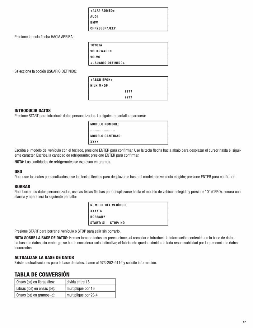
47
<ALFA ROMEO>
AUDI
BMW
CHRYSLER/JEEP
Presione la tecla flecha HACIA ARRIBA:
TOYOTA
VOLKSWAGEN
VOLVO
<USUARIO DEFINIDO>
Seleccione la opción USUARIO DEFINIDO:
<ABCD EFGH>
HIJK MNOP
????
????
INTRODUCIR DATOSPresione START para introducir datos personalizados. La siguiente pantalla aparecerá:
MODELO NOMBRE:
. . . . . . . . . . . . . . . . . . . . . .
MODELO CANTIDAD:
XXXX
Escriba el modelo del vehículo con el teclado, presione ENTER para confirmar. Use la tecla flecha hacia abajo para desplazar el cursor hasta el sigui-ente carácter. Escriba la cantidad de refrigerante; presione ENTER para confirmar.
NOTA: Las cantidades de refrigerantes se expresan en gramos.
USOPara usar los datos personalizados, use las teclas flechas para desplazarse hasta el modelo de vehículo elegido; presione ENTER para confirmar.
BORRARPara borrar los datos personalizados, use las teclas flechas para desplazarse hasta el modelo de vehículo elegido y presione “0” (CERO). sonará una alarma y aparecerá la siguiente pantalla:
NOMBRE DEL VEHÍCULO
XXXX G
BORRAR?
START: SÍ STOP: NO
Presione START para borrar el vehículo o STOP para salir sin borrarlo.
NOTA SOBRE LA BASE DE DATOS: Hemos tomado todas las precauciones al recopilar e introducir la información contenida en la base de datos. La base de datos, sin embargo, se ha de considerar solo indicativa; el fabricante queda eximido de toda responsabilidad por la presencia de datos incorrectos.
ACTUALIZAR LA BASE DE DATOSExisten actualizaciones para la base de datos. Llame al 973-252-9119 y solicite información.
TABLA DE CONVERSIÓNOnzas (oz) en libras (lbs): divida entre 16
Libras (lbs) en onzas (oz): multiplique por 16
Onzas (oz) en gramos (g): multiplique por 28,4
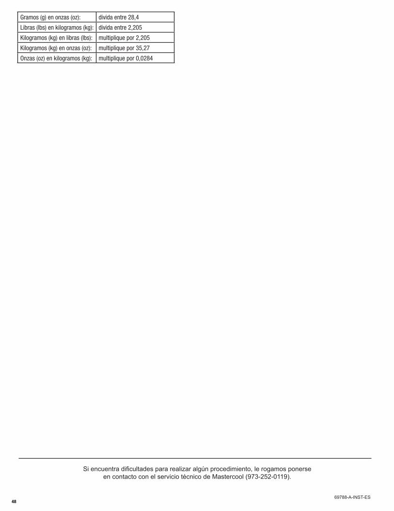
48
Si encuentra dificultades para realizar algún procedimiento, le rogamos ponerse en contacto con el servicio técnico de Mastercool (973-252-0119).
69788-A-INST-ES
Gramos (g) en onzas (oz): divida entre 28,4
Libras (lbs) en kilogramos (kg): divida entre 2,205
Kilogramos (kg) en libras (lbs): multiplique por 2,205
Kilogramos (kg) en onzas (oz): multiplique por 35,27
Onzas (oz) en kilogramos (kg): multiplique por 0,0284