rectification of defects in cylinder frame casting … · rectification of defects in cylinder...
TRANSCRIPT

International Journal of Scientific & Engineering Research, Volume 8, Issue ƘȮɯ ×ÙÐÓɪƖƔƕƛɯɯɯɯɯ ISSN 2229-5518
IJSER © 2017
http://www.ijser.org
RECTIFICATION OF DEFECTS IN CYLINDER FRAME CASTING
Rashid M P, Mohammed Jaseem N K, Muhammed Mubarak T, Muhammed Afsal K P, Mohammed Hisham E K, Sarath N
Abstract— Casting is a process which carries risk of failures occurrence during all the process of accomplishment of the finished
product. Hence necessary action should be taken while manufacturing of cast product so that defect free parts are obtained.
Mostly casting defects are concerned with process parameters. Even in completely controlled process, defects in casting are
observed and hence casting process is also known as process of uncertainty which challenges the explanation about the cause of
casting defects.The objective of the project is to rectify the errors associated with casting of the cylinder frame.
Index Terms— Casting, Casting defecs,Inspection, Poldi test,D P test, , Remedial measures
—————————— —————————— 1.INTRODUCTION
he Metal casting is the one of the direct method of manu-
facturing the desired geometry of components. it is also
known as near net shape process. The Autokast Ltd is
casting industry, which produce different castings for cus-
tomer needs. The cylinder frame is the one of the product of
Autokast Ltd. Cylinder frame is an integral part of the ma-
chines which houses the engine cylinders and associated
engine structures such as coolant passages, intake and ex-
haust passages, ports and crankcase. Cylinder frame used
machines such as tractors,Power tillers etc.
The aim of our project is to rectify the defects associated
with cylinder frame and to suggest remedial measures to
rectify it. Casting process is based on the property of a liquid
to take up the shape of a vessel containing it. When molten
metal solidifies it takes the shape of a mould but not exactly
the same because there is reduction of volume due to
shrinkage. In order to compensate for shrinkage of metal,
suitable provisions is to be provided. Thus casting is one of
the most versatile forms of mechanical process for produc-
tion, because there is no limit to size, shape and intricacy of
the articles that can be produced by casting.
The major target of this project is to identify the root
causes of the defects formed and to rectify it, at minimum
cost. We think this attempt will reduce the chances of fail-
ures during production. This project have important role in
attaining quality of the product. An attempt is made to mod-
ify the physical and dimensional constraints to eradicate
uneven distribution of molten metal, usage of pre heated
cores all of which are described in detail in this report.
2 LITERATURE REVIEW 2.1 CASTING
Casting is a manufacturing process in which a
liquid material is usually poured into a mold, which
contains a hollow cavity of the desired shape, and then
allowed to solidify. The solidified part is also known as a
casting, which is ejected or broken out of the mold to
complete the process.
Mostly casting defects are concerned with process
parameters. Hence one has to control the process parameter
to achieve zero defect parts. For controlling process
parameter it is essential to have knowledge about effect of
process parameter on casting and their influence on defect.
Number of researchers has worked for defect minimisation
through process improvement using various tools. A brief
review discussed further.
Narayanswamy and Natrajan [1] reviewed various
casting defects. They categorise defects into filling related
defects (FRD), shape related defects (SRD), thermal defects
(TD) and defects by appearance. The monthly percentage of
rejection due to these defects is varying from 12.86 % to 15.01
%. The filling related defects are further classified as sand
inclusion, rough surface, scabbing, blow holes, chill blow,
clay ball hole, sand fusion, and pin holes. Sand related
defects are also further classified as mould lift, mould
broken, and shift, leakage. The defects by appearance are
categorized as DBS blast core missing, swelling, and no core.
Out of these defects the filling related defects are to be given
importance for the analysis and it is mainly due to the
quality of sand. The shape related defects, defects by
appearance and thermal defects are due to various factors in
mould making process and melting process. Using the
modern method and suitable techniques, it is really a boon
for the foundry sector to produce quality casting to satisfy
the customer requirement. They concluded that quality of
castings depends on quality of sand, method of operation,
quality of molten metal and environmental conditions etc.
Dr. Shivappa D.N [2] studied TSB castings revealed
that the contribution of the four prominent defects in casting
rejections are sand drop, blow hole, mismatch, and oversize.
T
————————————————
Mohammed Jaseem N K, Muhammed Mubarak T, Muhammed
Afsal K P, Mohammed Hisham E K, Sarath N are currently pur-
suing bachilors degree program in mechanical engineering in
Eranad Knowledge City Technical Campus Manjeri, kerala, in-
dia, PH-7034000327 E-mail: [email protected].
Rashid M P, assistant professor in mechanical engineering in
Eranad Knowledge City Technical Campus Manjeri, kerala, in-
dia, PH-9895058428. E-mail: [email protected]
1637
IJSER
International Journal of Scientific & Engineering Research, Volume 8, Issue ƘȮɯ ×ÙÐÓɪƖƔƕƛɯɯɯɯɯ ISSN 2229-5518
IJSER © 2017
http://www.ijser.org
It was noticed that these defects are frequently occurring at
particular locations. Systematic analysis were carried out to
understand the reasons for defects occurrence and the
reasons identified are; the causes of sand drop were found
due to improper cleaning of mould in the areas around chills
and mould interface, sleeve, and breaker core. Blow holes
occurrence around long member is due to failure to connect
flow off in the gating design. The mismatch of castings is
due to lack of locators and improper setting of cores. Casting
oversize is due to mould lift and mould bulging. Remedial
measures identified to overcome the above defects are; (i)
Sand drop: proper cleaning of the mould before closing,
ensure that sand don’t enter into the sleeve, replace no bake
core with shell core, provide pads at bottom face, and
modified the loose piece design to avoid core crushing. (ii)
Blow hole: modification of gating system; flow offs are to be
directly connected on top surface of long member. (iii)
Mismatch: provided six locators for proper setting of cores -
three are of metallic and three are self-locators. (iv) Over
size: clamp the moulds properly to withstand the pouring
pressure. Production trials were carried out in the foundry
for four months period by incorporating the above remedial
measures and validated. Outcome of the results showed
substantial reduction in rejection of castings.
Sarath and Rathish [3] suggested new approach to
produce sound Fg260 gray iron casting by computer
simulation through experimental validation in a cast iron
foundry. The casting process is simulated by using finite
element simulation software and results were compared. A
simple rectangular plate casting dimension 200*100*15 mm
is produced with different combination of riser dimensions.
To improve the yield and minimise defect, cylindrical riser of
hemispherical bottom width h/d=1.3was considered. Ansys
simulation software was used to compute solidification time
and selection of optimal riser dimensions. It was proven by
researchers that hemispherical bottom riser consumes 16-17
% less metal than standard cylindrical side riser.
Experimental verification was also done to validate results
obtained by simulation.
Singh and Kumar [4] analysed defects of check valve
namely cold shut, scab and shrinkage. Reduction of causes
of these defects like pouring temperature, permeability,
mould hardness and sand particles optimised through
taguchi's method. In their work l9 orthogonal array is used
for the trial purpose. The response of the s/n ratio,
contribution of different process parameters and relation
between s/n ratio and the levels of different process
parameters is studied and analyzed to obtain optimum
process parameters. After implementation various
experiments and testing techniques they concluded that the
optimum value of pouring temperature is 13400 c,
permeability is 150(no) , sand particle size is 42 AFS and
mould hardness number is 91.132 .
Mane V.V [5] carried out casting defect analysis by using
techniques like cause-effect diagrams, design of
experiments, if-then rules and artificial neural network.
Researcher describes 3-step approach to casting defect
identification, analysis and rectification. The defects are
classified in terms of their appearance, size, location,
consistency and discovery stage and inspection method. This
helps in correct identification of defects. For defect analysis,
the possible causes are grouped into design, material and
process parameters. The effect of suspected cause
parameters on casting quality is ascertained through
simulation. Based on the results and their interpretation, the
optimal values are determined to eliminate defects.
2.2 CASTING DEFECTS
Foundry industries in developing countries suffer from
poor quality and productivity due to involvement of number
of process parameter. Even in completely controlled process,
defect in casting are observed and hence casting process is
also known as process of uncertainty which challenges the
explanation about the cause of casting defects. In order to
identify the casting defect and problem related to casting,
the study is aimed in the research work. This will be
beneficial in enhancing the yield of casting. Beside this,
standardization (optimization) of process parameter for
entire cycle of manufacturing of the critical part is intended
in the proposed work.
This study aims to finding different defects in casting,
analysis of defect and providing their remedies with their
causes. This paper also aims to provide correct guideline to
quality control department to find casting defects and will
help them to analyse defects which are not desired.
Casting is a process which carries risk of failure
occurrence during all the process of accomplishment of the
finished product. Hence necessary action should be taken
while manufacturing of cast product so that defect free parts
are obtained. Mostly casting defects are concerned with
process parameters. Hence one has to control the process
parameter to achieve zero defect parts. For controlling
process parameter one must have knowledge about effect of
process parameter on casting and their influence on defect.
To obtain this all knowledge about casting defect, their
causes, and defect remedies one has to be analyse casting
defects. Casting defect analysis is the process of finding root
causes of occurrence of defects in the rejection of casting and
taking necessary step to reduce the defects and to improve
the casting yield. In this review paper an attempt has been
made to provide all casting related defect with their causes
and remedies. During the process of casting, there is always
a chance where defect will occur. Minor defect can be
adjusted easily but high rejected rates could lead to
1638
IJSER
International Journal of Scientific & Engineering Research, Volume 8, Issue ƘȮɯ ×ÙÐÓɪƖƔƕƛɯɯɯɯɯ ISSN 2229-5518
IJSER © 2017
http://www.ijser.org
significant change at high cost. Therefore it is essential for
die caster to have knowledge on the type of defect and be
able to identify the exact root cause, and their remedies.
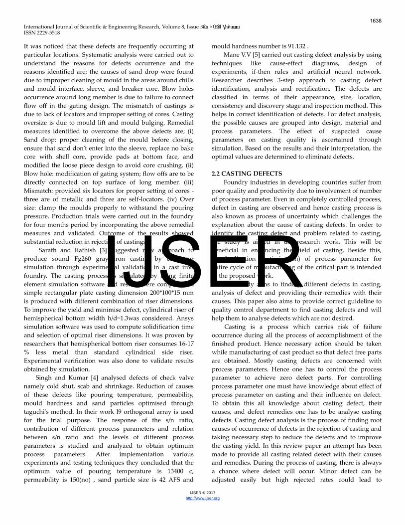
Fig 2:1 Variation Of Tensile Strength And Cross Sectional
Thickness Of Grey Cast Iron
Fig 2:2 Mechanical Test Requirements
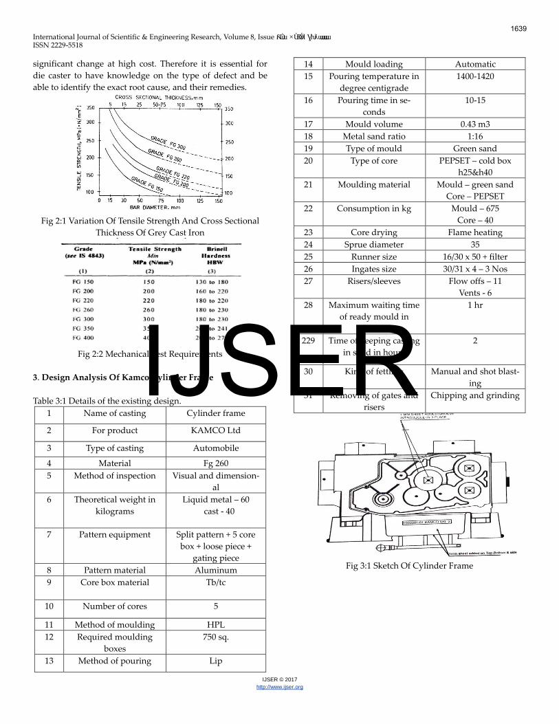
3. Design Analysis Of Kamco Cylinder Frame
Table 3:1 Details of the existing design.
1 Name of casting Cylinder frame
2 For product KAMCO Ltd
3 Type of casting Automobile
4 Material Fg 260
5 Method of inspection Visual and dimension-
al
6 Theoretical weight in
kilograms
Liquid metal – 60
cast - 40
7 Pattern equipment Split pattern + 5 core
box + loose piece +
gating piece
8 Pattern material Aluminum
9 Core box material Tb/tc
10 Number of cores 5
11 Method of moulding HPL
12 Required moulding
boxes
750 sq.
13 Method of pouring Lip
14 Mould loading Automatic
15 Pouring temperature in
degree centigrade
1400-1420
16 Pouring time in se-
conds
10-15
17 Mould volume 0.43 m3
18 Metal sand ratio 1:16
19 Type of mould Green sand
20 Type of core PEPSET – cold box
h25&h40
21 Moulding material Mould – green sand
Core – PEPSET
22 Consumption in kg Mould – 675
Core – 40
23 Core drying Flame heating
24 Sprue diameter 35
25 Runner size 16/30 x 50 + filter
26 Ingates size 30/31 x 4 – 3 Nos
27 Risers/sleeves Flow offs – 11
Vents - 6
28 Maximum waiting time
of ready mould in
hours
1 hr
229 Time of keeping casting
in sand in hours
2
30 Kind of fettling Manual and shot blast-
ing
31 Removing of gates and
risers
Chipping and grinding
Fig 3:1 Sketch Of Cylinder Frame
1639
IJSER

International Journal of Scientific & Engineering Research, Volume 8, Issue ƘȮɯ ×ÙÐÓɪƖƔƕƛɯɯɯɯɯ ISSN 2229-5518
IJSER © 2017
http://www.ijser.org
Fig 3:2 Drawing Of Cylinder Frame
4. TEST DETAILS 4.1 Poldi Test
The poldi hardness tester is one of the portable hardness
testers. The indentation is obtained on the test surface by
striking a blow on the ball which also produces indentation
on the standard bar. The diameter of the indentation on the
test surface and the standard bar are correlated in the manu-
facturer’s table and the hardness number is measured in
BHN.
Fig 4:1 Poldi Hardness Testing
Test Result
Table 4:1 Composition Of Elements, Tensile value and
Hardness value
CYLINDER FRAME TEST RESULT
Sl No Chemistry Of
Material
Tensile Value
UTM, (N/ mm2)
Hardness
BHN
1
C
Mn
Si
P
S
3.1
0.6
1.6
0.1
0.12
260
176
Fg 260 grade cast iron is used for the production of cyl-
inder frame casting and these composition of materials such
as carbon, manganese, silicon etc are within the standard
range of fg 260 cast iron. The required tensile strength of the
cylinder frame casting is greater than or equal to 260. The
tensile strength obtained for this composition is satisfactory
from the test result while the required hardness test is great-
er than or equal to 180, but the obtained strength in the test
is not satisfactory for the cylinder frame casting.
Table 4:2 Changed Composition Of Elements, Tensile value
and Hardness value
When small amount of carbon and silica is added,
then the amount the value of hardness in poldi test increases
to the required rate. The tensile strength is obtained as 291
n/mm2 and the hardness in BHN is obtained as 186 and both
these values are within the required range. By increasing this
element, the grade of the metal may change. The new
amount of the carbon and silicon comes under the fg150
grade cast iron.
4.2. Dye Penetrant Test
Dye penetrant inspection also called liquid pene-
trant inspection or penetrant testing is a widely applied and
low-cost inspection method used to locate surface-breaking
defects in all non-porous materials.
Observation
Cracks can appear in die castings from a number of
causes. Some cracks are very obvious and can easily be seen
with the naked eye. Other cracks are very difficult to see
without magnification. The highlighted area in figure is the
part of the cylinder frame is the place where the oil is stored
and this part should be completely crack free part. Any sort
of cracks in this part will lead to the leakage of the oil which
will leads to the complete rejection of the part.
Fig 4:2Die Penetrant Testing
Suggestions
Reduce dry strength, add saw dust/ coal dust, avoid
superheating of metal, use chills, provide feeders, correct
composition, and reduce sharp corners. Applying these
steps in casting will leads to defects free casting.
CYLINDER FRAME TEST RESULT
Sl
No
Chemistry Of Material
Tensile Value
UTM, (N/ mm2)
Hardness
BHN
1
C
Mn
Si
P
S
3.62
0.6
2.18
0.08
0.09
291
186
1640
IJSER

International Journal of Scientific & Engineering Research, Volume 8, Issue ƘȮɯ ×ÙÐÓɪƖƔƕƛɯɯɯɯɯ ISSN 2229-5518
IJSER © 2017
http://www.ijser.org
4.3. Dimensional Checking With Gauge
Fig 4:3 Test Using Gauge Special Gauge Used For Cylinder
Frame
This gauge shown in figure is used for checking the
dimensional accuracy of the cylinder frame. This gauge is
specially designed for the cylinder frame casting. The over
size or under size of the diameters of the holes in the
cylinder frame can be easily checked by using this gauges.
Suggestions
Check pattern mounting on match plate and rectify,
correct dowel
Use proper moulding box and closing pins
4.4 Visual Inspection
Fig 4:6 Visual Inspection: Sand Inclusion
Fig 4:4 Visual Inspection: Blow Hole
Visual inspection is the commonly used method
used to check the defects in casting. The cylinder frame cast-
ing is a hollow frame with wall thickness 14 mm. Since the
thickness is very small the inspections such as ultrasonic
inspection, radiography etc cannot be done on it.
Suggestions
Increase the strength of the cores. Use greater pro-
portion of binder.
Check moulds for pressure marks and, if necessary,
insert pressure pads
Carefully blow out mould cavities
Check the moulding plant for uniform flask strip-
ping and overhaul moulding plant as necessary
Ensure uniform mould compaction, avoid over
compacted sections clay bonded sand
For blow holes
Make adequate provision for evacuation of air and
gas from the mold cavity.
Increase permeability of mold and cores.
Table 4:3 Test Result And Conclusions
5 CONCLUSION
The project was conducted on rectification of defects
formed in the casting of cylinder frame at Autokast Ltd. We
were able to learn in detail about the casting methods
involved for the manufacturing of different castings. The
data received was put in to good use through the computing
skills that we were able to procure during our time here at
the company. Casting defects cause a serious problem in
foundry industry often leading to losses of raw materials
and financial loss.
The main defects identified are crack, blow hole,
sand inclusion, and shrinkage. The defect crack is due to lack
of strength and it has been rectified by varying the
composition of the elements and the solutions for the other
defects are suggested.
Sl.
N
o
Test Con-
ducted
Problem
Identi-
fied
Solution
1 Poldi Test Strength Improve composition by
adding small amount of
carbon and silicon
2
Die Pene-
trant Test
Crack
Avoid super heating of
metal
Reduce sharp corners
Use chills
3
Test Using
Gauges
Dimen-
sional
Error
Check pattern mounting
on match plate
Using moulding box and
closing pins
4
Visual In-
spection
Sand
Inclu-
sion
increase core strength
Ensure uniform mould
compaction, avoid over
compacted sections clay
bonded sand
1641
IJSER

International Journal of Scientific & Engineering Research, Volume 8, Issue ƘȮɯ ×ÙÐÓɪƖƔƕƛɯɯɯɯɯ ISSN 2229-5518
IJSER © 2017
http://www.ijser.org
6 ACKNOWLEDGMENT
We would remember with grateful appreciation, the
encouragement and support rendered by the Principal Dr. B
PRIESTLY SHAN of Eranad Knowledge City, Manjeri.
We express our deepest sense of gratitude to Head of
the Department, Mr. SALEEM N and our internal guide Mr.
RASHID M P, Assistant professor of Mechanical
Engineering for their valuable advice and guidance.
We also express our sense of gratitude to external
guide Mr. ARUN at Autokast Ltd for his valuable advice.
We would always oblige for the helping hands of all
other staff members of the department and all our friends
and well-wishers, who directly or indirectly contributed in
this venture.
Last but not least, we are indebted to God Almighty
for being the guiding light throughout this project and
helped us to complete the same within the stipulated time.
7 REFERENCES
[1] Narayanswamy.c, Natrajan.k, review analysis of
casting defect with respect to Indian standards in
cast iron foundry, journal of chemical and pharma-
ceutical science,2(2016)63-68,issn:0974-2115.
[2] Dr. Shivappa. D.N, Rohit, Bhattacharya Abhijit,
analysis of casting defect and identification of re-
medial measures-a diagnostic study, international
journal of engineering inventions,6(2012)01-
05,issn:2278-7461.
[3] Sarath p, Rathish r, simulation and experimental
validation of feeding efficiency in FG 260 gray cast
iron casting, international journal of research and
general science, 2(2014)797-811.
[4] Singh Harvir, Kumar Aman, minimisation of cast-
ing defects using Taguchi’s method, international
journal of engineering science inovation,5(2016)6-
10,issn:2319-6734
[5] Mane V.V, Sata A, Khire M .Y, new approach to
casting defects classification and analysis supported
by simulation, 2011
[6] R.K Rajput, a text book of manufacturing technolo-
gy (manufacturing process), new Delhi, Lakshmi
publications (p) ltd, 2007
[7] Principles of foundry technology – p l Jain.
[8] www.autokast.com
1642
IJSER