red th for in aramid olecular-weight polyethylene · photograph of a thick aramid panel is shown in...
TRANSCRIPT
DefenExternaDRDC-RJune 20
Infraand UArmo
Marc GenNational R Simon OuKevin WillDRDC – V ThermoseThermoseOrlando, U Date of Pu
ce Reseal LiteratureRDDC-201818
red ThUltra-Hor Sys
est Research Cou
uellet iams
Valcartier Res
ense 2018 ense conferenUSA
ublication from
earch ane (N) 8-N086
hermogHigh-Mtems
uncil Canada,
search Centre
nces
m Ext Publish
nd Deve
CAN U
CAN UNCLA
graphyMolecul
, Aerospace R
e
her: April 2018
lopment
UNCLASSIFIE
ASSIFIED
y for Inlar-We
Research Cen
8
t Canad
ED
nspectieight P
ntre
a
ion of olyeth
Aramihylene
d

Template in use: CR_EL1%20Advanced%20Template_EN%202018-04_04-v1_WW.DOTM
© Her Majesty the Queen in Right of Canada (Department of National Defence), 2018 © Sa Majesté la Reine en droit du Canada (Ministère de la Défense nationale), 2018
CAN UNCLASSIFIED
CAN UNCLASSIFIED
IMPORTANT INFORMATIVE STATEMENTS
This document was reviewed for Controlled Goods by Defence Research and Development Canada (DRDC) using the Schedule to the Defence Production Act.
Disclaimer: This document is not published by the Editorial Office of Defence Research and Development Canada, an agency of the Department of National Defence of Canada but is to be catalogued in the Canadian Defence Information System (CANDIS), the national repository for Defence S&T documents. Her Majesty the Queen in Right of Canada (Department of National Defence) makes no representations or warranties, expressed or implied, of any kind whatsoever, and assumes no liability for the accuracy, reliability, completeness, currency or usefulness of any information, product, process or material included in this document. Nothing in this document should be interpreted as an endorsement for the specific use of any tool, technique or process examined in it. Any reliance on, or use of, any information, product, process or material included in this document is at the sole risk of the person so using it or relying on it. Canada does not assume any liability in respect of any damages or losses arising out of or in connection with the use of, or reliance on, any information, product, process or material included in this document.
Infrared Thermography for Inspection of Aramid and Ultra-High-Molecular-Weight Polyethylene Armor Systems
Marc Genesta, Simon Ouelletb, Kevin Williamsb aNational Research Council Canada, Aerospace Research Centre, 1200 Montreal Rd, Ottawa, ON,
Canada, K1A 0R6; bDepartment of National Defence, Defence Research and Development Canada, 2459 route de la
Bravoure, Québec, QC, Canada, G3J 1X5
ABSTRACT
Non-Destructive Evaluation (NDE) trials were performed on aramid and ultra-high molecular-weight polyethylene (UHMWPE) based armor systems. Pulsed thermography, continuous heating, and lock-in thermography were investigated for various types of damage. It is shown that the infrared thermography results vary significantly based on the material and thickness of the armor system, and only certain types of damage can be confidently identified. While the pulsed thermography performed in reflection mode was the fastest and provided the strongest indication signal for some types of damage, deeper damage on thicker armor system needed to be performed in transmission mode. Due to inherent material properties variations in these armor systems, the infrared images were affected by non-uniformity. In addition, due to low thermal conductivity, the inspections were sporadically affected by non-uniform heating. Approaches are presented to address the non-uniform heating issue affecting the inspection of those low thermal conductivity materials. Keywords: Infrared Thermography, Aramid, Ultra-high molecular-weight polyethylene,
1. INTRODUCTION
The need for lighter personal protective equipment (PPE) has led to the development of new ballistic protection materials. Although these newer materials meet the ballistics protection requirements, the very lightweight armour systems that are now feasible could present durability challenges over their service life. This is compounded by the fact that there are very few recognized non-destructive evaluation (NDE) methods that can reliably assess the laminate armor materials. Therefore, the industry generally relies on destructive batch testing to assess the current state of personal armors (helmets and body armors). The requirements for field implementation of NDE technology in the case of personal armors are that it must be simple, lightweight and durable to meet the demands of the battlefield must be reliable and sensitive to critical levels of damage that would affect protective performance, and must have a sufficient throughput (e.g. minutes per armor plate, or minutes per helmet) to be of value. The United States Government standards require personnel armors to be damage-free to guarantee effectiveness [1]. For body armor systems, research has shown strong correlations between reduction in armor performance and the presence of porosity, cracking, and separations between the different layers. Body armors experience a wide range of low-level energy impacts on and off the battlefield. Low velocity impact is the major source of non-ballistic damage that can lead to ballistic performance degradation.
The high cost (manufacturing and raw materials) of armor systems is a strong economic driver for investments in technologies that ensure extended service life while maintaining the integrity (e.g. damage free) of armor system and performance during the period of service. NDE techniques are required to rapidly and non-destructively determine the extent of damage armors have experienced and then the damage can be used to assess the helmet performance. The selection of an appropriate NDE technique requires consideration of the armor material and the types and critical sizes of flaws likely to occur. In addition, NDE techniques could help with quality control during manufacturing of armour systems.
2. SPECIMEN
2.1 Aramid panels
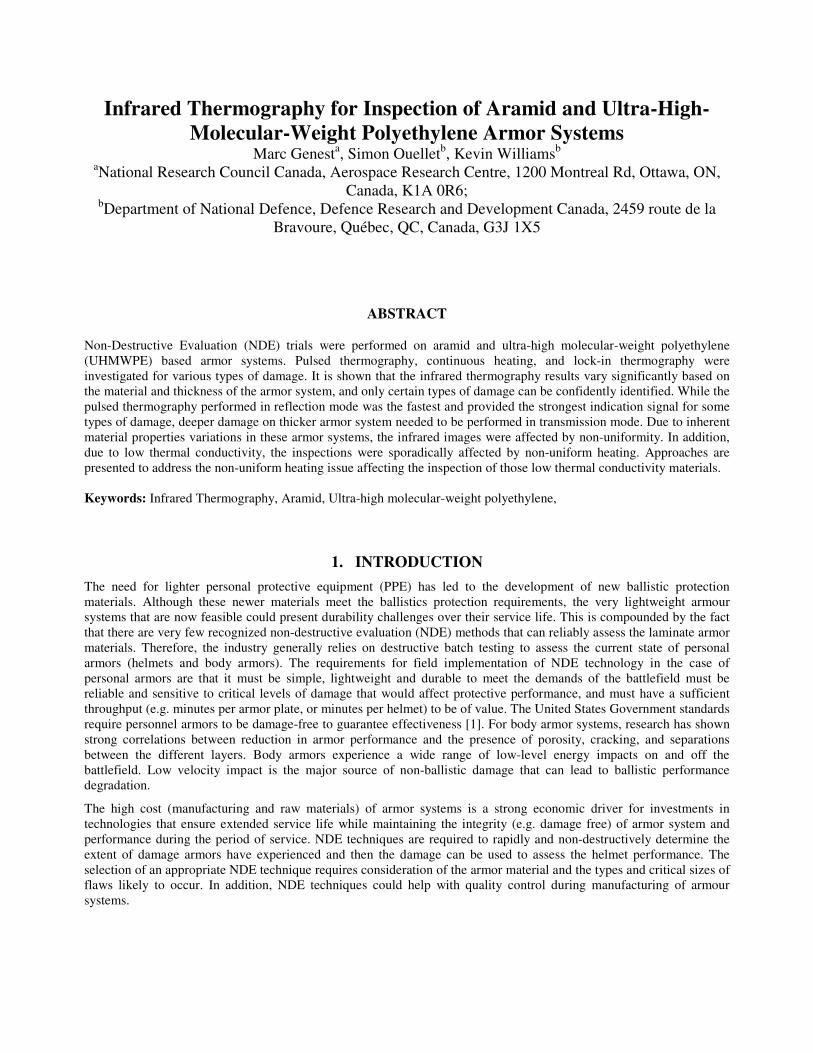
Aramid fiber panels, having dimension 8 inch by 8 inch, of two different thicknesses were used. The first set had a nominal thickness of 0.125 inch (3.2 mm), referred to as thin panels, while the second set were 0.275 inch (7 mm) thick and referred to as thick panels. Both sets were subjected to impact with energy levels varying from 10 J to 120 J. A photograph of a thick aramid panel is shown in Figure 1. The thin panels were made up of two different groups: #50 and #51. Panels 50 (A, B, D) were made of Kevlar® KM2 fibers, with the fabric architecture being a plain weave, made of 16 layers. A Nylon polymer matrix was used and the panels had a fiber content of 87% (13% matrix content). Panels 51(A, C, D) used similar material than that of panels 50 but with a lower fiber content of 67% (33% matrix content). The thick panels were manufactured using the same Kevlar® KM2 fibers and nylon polymer matrix. They were made of 47 layers of fabric and their fiber content was around 85% (15% matrix content).
Figure 1: Photograph of a thick aramid based panel.
2.2 Ultra-high-molecular-weight polyethylene based panels
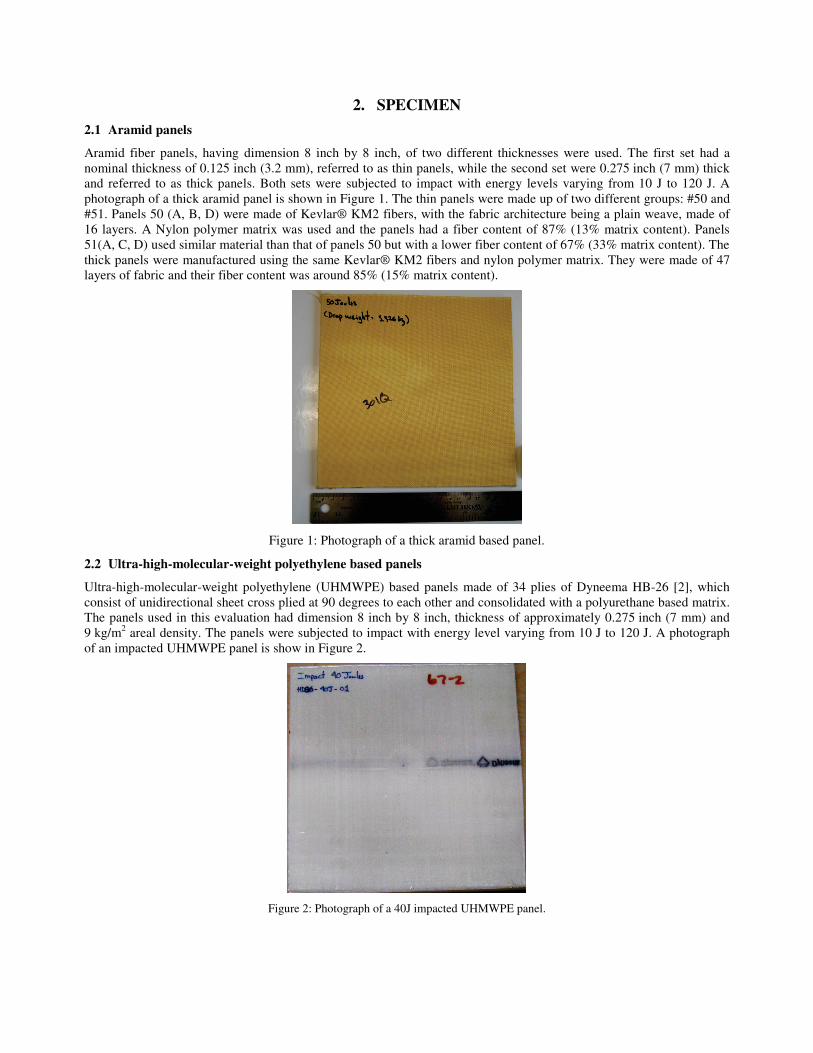
Ultra-high-molecular-weight polyethylene (UHMWPE) based panels made of 34 plies of Dyneema HB-26 [2], which consist of unidirectional sheet cross plied at 90 degrees to each other and consolidated with a polyurethane based matrix. The panels used in this evaluation had dimension 8 inch by 8 inch, thickness of approximately 0.275 inch (7 mm) and 9 kg/m2 areal density. The panels were subjected to impact with energy level varying from 10 J to 120 J. A photograph of an impacted UHMWPE panel is show in Figure 2.
Figure 2: Photograph of a 40J impacted UHMWPE panel.
2.3 Helmets
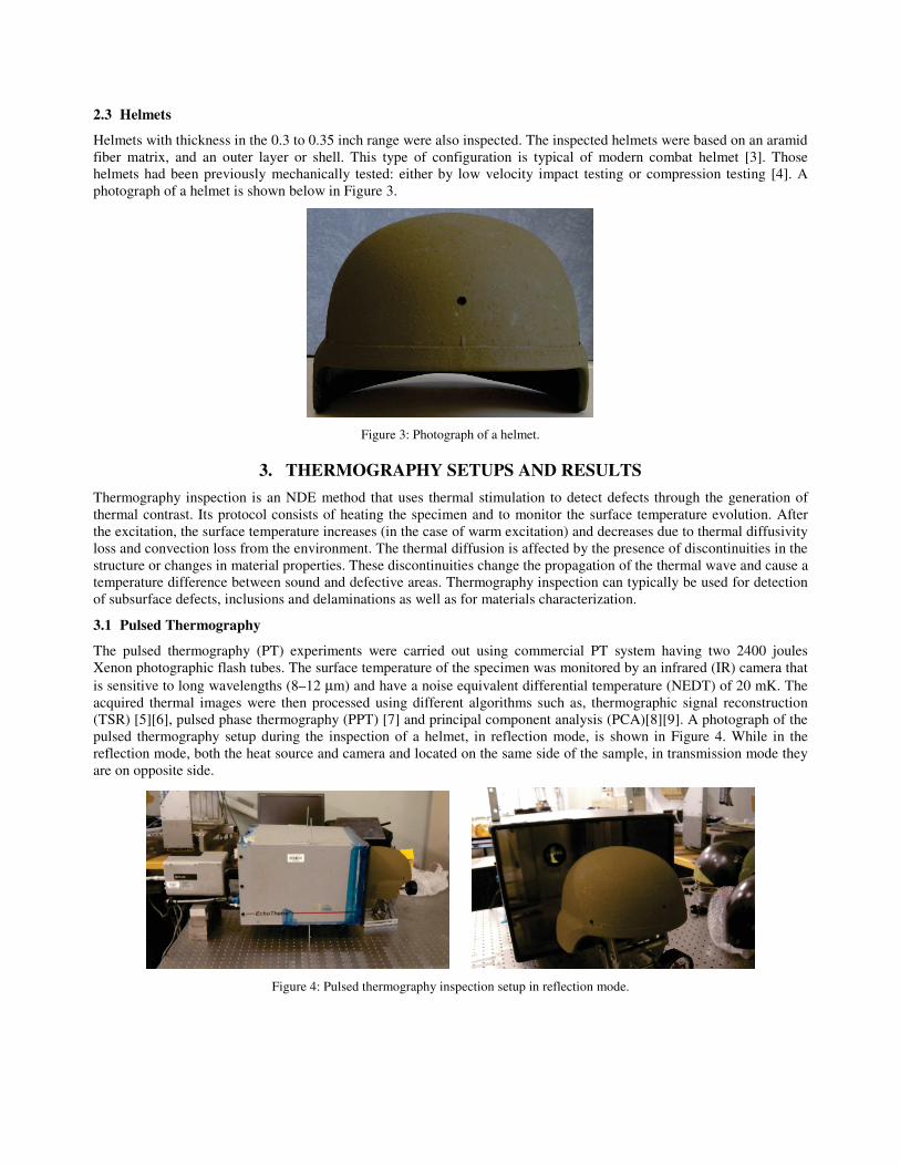
Helmets with thickness in the 0.3 to 0.35 inch range were also inspected. The inspected helmets were based on an aramid fiber matrix, and an outer layer or shell. This type of configuration is typical of modern combat helmet [3]. Those helmets had been previously mechanically tested: either by low velocity impact testing or compression testing [4]. A photograph of a helmet is shown below in Figure 3.
Figure 3: Photograph of a helmet.
3. THERMOGRAPHY SETUPS AND RESULTS
Thermography inspection is an NDE method that uses thermal stimulation to detect defects through the generation of thermal contrast. Its protocol consists of heating the specimen and to monitor the surface temperature evolution. After the excitation, the surface temperature increases (in the case of warm excitation) and decreases due to thermal diffusivity loss and convection loss from the environment. The thermal diffusion is affected by the presence of discontinuities in the structure or changes in material properties. These discontinuities change the propagation of the thermal wave and cause a temperature difference between sound and defective areas. Thermography inspection can typically be used for detection of subsurface defects, inclusions and delaminations as well as for materials characterization.
3.1 Pulsed Thermography
The pulsed thermography (PT) experiments were carried out using commercial PT system having two 2400 joules Xenon photographic flash tubes. The surface temperature of the specimen was monitored by an infrared (IR) camera that is sensitive to long wavelengths (8–12 μm) and have a noise equivalent differential temperature (NEDT) of 20 mK. The acquired thermal images were then processed using different algorithms such as, thermographic signal reconstruction (TSR) [5][6], pulsed phase thermography (PPT) [7] and principal component analysis (PCA)[8][9]. A photograph of the pulsed thermography setup during the inspection of a helmet, in reflection mode, is shown in Figure 4. While in the reflection mode, both the heat source and camera and located on the same side of the sample, in transmission mode they are on opposite side.
Figure 4: Pulsed thermography inspection setup in reflection mode.
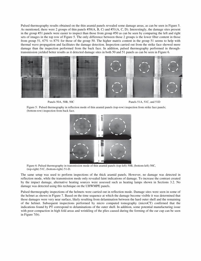
Pulsed thermography results obtained on the thin aramid panels revealed some damage areas, as can be seen in Figure 5. As mentioned, there were 2 groups of thin panels #50(A, B, C) and #51(A, C, D). Interestingly, the damage sites present in the group #51 panels were easier to inspect than those from group #50 as can be seen by comparing the left and right sets of images in the top row of Figure 5. The only difference between those 2 groups is the lower fiber content in those from group 51, 67% vs 87% for those of the group 50. The higher matrix content in the group 51 seems to help with thermal wave propagation and facilitates the damage detection. Inspection carried out from the strike face showed more damage than the inspection performed from the back face. In addition, pulsed thermography performed in through-transmission yielded better results as it detected damage sites in both 50 and 51 panels as can be seen in Figure 6.
Panels 50A, 50B, 50C Panels 51A, 51C, and 51D
Figure 5: Pulsed thermography in reflection mode of thin aramid panels (top-row) inspection from strike face panels; (bottom-row) inspection from back face.
Figure 6: Pulsed thermography in transmission mode of thin aramid panels (top-left) 50B, (bottom-left) 50C, (top-right) 51C, (bottom-right) 51-D.
The same setup was used to perform inspections of the thick aramid panels. However, no damage was detected in reflection mode, while the transmission mode only revealed faint indications of damage. To increase the contrast created by the impact damage, alternative heating sources were assessed such as heating lamps shown in Sections 3.2. No damage was detected using this technique on the UHWMPE panels.
Pulsed thermography inspections of the helmets were carried out in reflection mode. Damage sites were seen in some of the helmet as shown in Figure 7. Based on the time sequence at which the damage become visible it was determined that those damages were very near surface, likely resulting from delamination between the hard outer shell and the remaining of the helmet. Subsequent inspections performed by micro computed tomography (microCT) confirmed that the indications found by PT correspond to delaminations of the outer shell. In addition, some potential manufacturing issue with poor compaction in high fold areas and wrinkling of the plies caused during the forming of the ear cup can be seen in Figure 7(b).
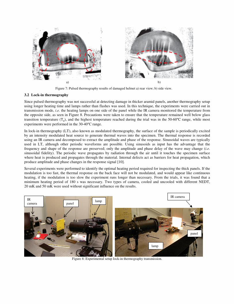
a) b)
Figure 7: Pulsed thermography results of damaged helmet a) rear view; b) side view.
3.2 Lock-in thermography
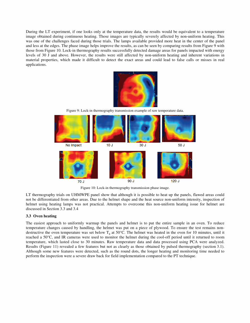
Since pulsed thermography was not successful at detecting damage in thicker aramid panels, another thermography setup using longer heating time and lamps rather than flashes was used. In this technique, the experiments were carried out in transmission mode, i.e. the heating lamps on one side of the panel while the IR camera monitored the temperature from the opposite side, as seen in Figure 8. Precautions were taken to ensure that the temperature remained well below glass transition temperature (Tg), and the highest temperature reached during the trial was in the 50-60 C range, while most experiments were performed in the 30-40 C range.
In lock-in thermography (LT), also known as modulated thermography, the surface of the sample is periodically excited by an intensity modulated heat source to generate thermal waves into the specimen. The thermal response is recorded using an IR camera and decomposed to extract the amplitude and phase of the response. Sinusoidal waves are typically used in LT, although other periodic waveforms are possible. Using sinusoids as input has the advantage that the frequency and shape of the response are preserved; only the amplitude and phase delay of the wave may change (i.e. sinusoidal fidelity). The periodic wave propagates by radiation through the air until it touches the specimen surface where heat is produced and propagates through the material. Internal defects act as barriers for heat propagation, which produce amplitude and phase changes in the response signal [10].
Several experiments were performed to identify the optimal heating period required for inspecting the thick panels. If the modulation is too fast, the thermal response on the back face will not be modulated, and would appear like continuous heating, if the modulation is too slow the experiment runs longer than necessary. From the trials, it was found that a minimum heating period of 180 s was necessary. Two types of camera, cooled and uncooled with different NEDT, 20 mK and 50 mK were used without significant influence on the results.
Figure 8: Experimental setup lock-in thermography transmission.
lamp
IR camera
panel
lamp IR camera panel
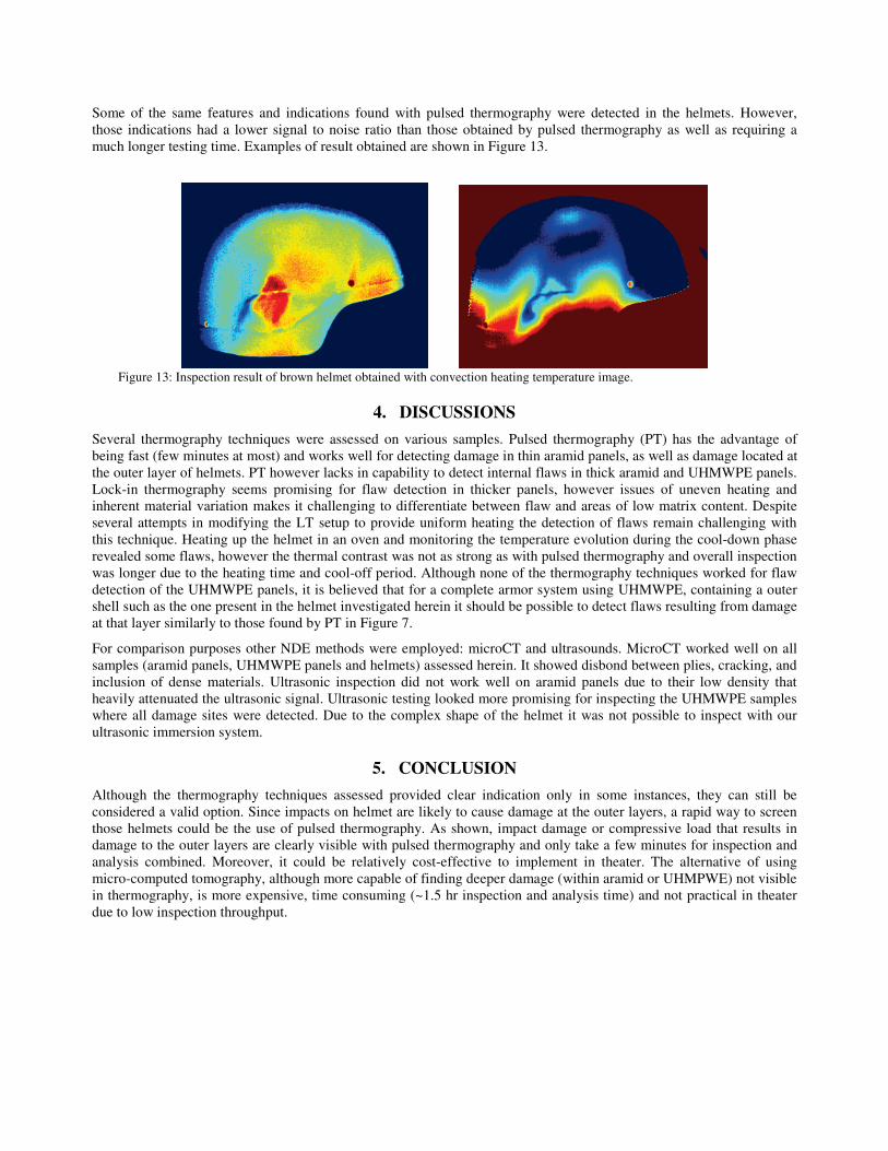
During the LT experiment, if one looks only at the temperature data, the results would be equivalent to a temperature image obtained during continuous heating. Those images are typically severely affected by non-uniform heating. This was one of the challenges faced during those trials. The lamps available provided more heat in the center of the panel and less at the edges. The phase image helps improve the results, as can be seen by comparing results from Figure 9 with those from Figure 10. Lock-in thermography results successfully detected damage areas for panels impacted with energy levels of 30 J and above. However, the results were still affected by non-uniform heating and inherent variations in material properties, which made it difficult to detect the exact areas and could lead to false calls or misses in real applications.
Figure 9: Lock-in thermography transmission example of raw temperature data.
Figure 10: Lock-in thermography transmission phase image.
LT thermography trials on UHMWPE panel show that although it is possible to heat up the panels, flawed areas could not be differentiated from other areas. Due to the helmet shape and the heat source non-uniform intensity, inspection of helmet using heating lamps was not practical. Attempts to overcome this non-uniform heating issue for helmet are discussed in Section 3.3 and 3.4
3.3 Oven heating
The easiest approach to uniformly warmup the panels and helmet is to put the entire sample in an oven. To reduce temperature changes caused by handling, the helmet was put on a piece of plywood. To ensure the test remains non-destructive the oven temperature was set below Tg at 50°C. The helmet was heated in the oven for 10 minutes, until it reached a 50°C, and IR cameras were used to monitor the helmet during the cool-off period until it returned to room temperature, which lasted close to 30 minutes. Raw temperature data and data processed using PCA were analyzed. Results (Figure 11) revealed a few features but not as clearly as those obtained by pulsed thermography (section 3.1). Although some new features were detected, such as the round dots, the longer heating and monitoring time needed to perform the inspection were a severe draw back for field implementation compared to the PT technique.

a) b)
c) d)
Figure 11: Thermography result a) helmet 1 front view; b) helmet 1 side view; c) helmet 2 front view; d) helmet 2 side view.
3.4 Internal convection heating
Another heating technique that was assessed for the inspection of helmets was the use of convection heating. For this trial, a custom convection heating system was developed in-house (Figure 12). It used 2 heating elements and a blower fan to circulate the hot air across copper tubing into a chamber to heat-up the inside of the helmet. The hot air from the chamber was recirculated in the copper tubing and fed back through the heating elements. The blower speed was controllable to adjust the heating and cooling. To reduce the heat loss, the copper tubing was insulated. This system was specifically developed for the inspection of helmets and the upper part of the chamber was carved so that the helmet can rest on it while IR cameras monitored the temperature evolution of the helmet outer layer. No panels were inspected with this system. The temperature of the heating elements, copper tubing, the inside and outside of the helmet was monitored using 4 thermocouples. A 2 minutes heat on, 2 minutes heat off cycles were applied. While the copper pipe fluctuated between 30 and 60°C, the helmet temperature fluctuated only by a few degrees between 25 and 30°C.
Figure 12: Setup of hot air convection system developed for the inspection of helmet.
Some of the same features and indications found with pulsed thermography were detected in the helmets. However, those indications had a lower signal to noise ratio than those obtained by pulsed thermography as well as requiring a much longer testing time. Examples of result obtained are shown in Figure 13.
Figure 13: Inspection result of brown helmet obtained with convection heating temperature image.
4. DISCUSSIONS
Several thermography techniques were assessed on various samples. Pulsed thermography (PT) has the advantage of being fast (few minutes at most) and works well for detecting damage in thin aramid panels, as well as damage located at the outer layer of helmets. PT however lacks in capability to detect internal flaws in thick aramid and UHMWPE panels. Lock-in thermography seems promising for flaw detection in thicker panels, however issues of uneven heating and inherent material variation makes it challenging to differentiate between flaw and areas of low matrix content. Despite several attempts in modifying the LT setup to provide uniform heating the detection of flaws remain challenging with this technique. Heating up the helmet in an oven and monitoring the temperature evolution during the cool-down phase revealed some flaws, however the thermal contrast was not as strong as with pulsed thermography and overall inspection was longer due to the heating time and cool-off period. Although none of the thermography techniques worked for flaw detection of the UHMWPE panels, it is believed that for a complete armor system using UHMWPE, containing a outer shell such as the one present in the helmet investigated herein it should be possible to detect flaws resulting from damage at that layer similarly to those found by PT in Figure 7.
For comparison purposes other NDE methods were employed: microCT and ultrasounds. MicroCT worked well on all samples (aramid panels, UHMWPE panels and helmets) assessed herein. It showed disbond between plies, cracking, and inclusion of dense materials. Ultrasonic inspection did not work well on aramid panels due to their low density that heavily attenuated the ultrasonic signal. Ultrasonic testing looked more promising for inspecting the UHMWPE samples where all damage sites were detected. Due to the complex shape of the helmet it was not possible to inspect with our ultrasonic immersion system.
5. CONCLUSION
Although the thermography techniques assessed provided clear indication only in some instances, they can still be considered a valid option. Since impacts on helmet are likely to cause damage at the outer layers, a rapid way to screen those helmets could be the use of pulsed thermography. As shown, impact damage or compressive load that results in damage to the outer layers are clearly visible with pulsed thermography and only take a few minutes for inspection and analysis combined. Moreover, it could be relatively cost-effective to implement in theater. The alternative of using micro-computed tomography, although more capable of finding deeper damage (within aramid or UHMPWE) not visible in thermography, is more expensive, time consuming (~1.5 hr inspection and analysis time) and not practical in theater due to low inspection throughput.
REFERENCES
[1] Fisher, J., “Validation of a Simple Go/No-go Damage Detection System for Personal Ceramic Body Armour using Pressure Sensitive Film”, Graduate Thesis and Dissertations Paper 10300, Iowa State University, (2011).
[2] https://www.dsm.com/content/dam/dsm/dyneema/en_GB/Downloads/LP%20Product%20Grades/DSM_PSS_HB26.pdf (March 12th, 2018)
[3] Lastnik, A.L., Barron, E. R., “Lightweight ballistic helmet”, US Patent 3,320,619A, (1967). [4] Anctil, B., Bayne, T., Williams, K., Fourny, P., Craigie, I., Savard, A., “Compression Resistance Testing of Combat
Helmets and the Effects on Ballistic Performance”, Personal Armor Systems Symposia 2014, 08 September 2014 - 12 September 2014, Cambridge, UK, (2014).
[5] Shepard, S. M. “Advances in Pulsed Thermography”, Andres E. Rozlosnik, Ralph B. Dinwiddie (eds.), Proc. SPIE, Thermosense XXIII, 4360, 511-515, (2001).
[6] Shepard, S. M., Ahmed, T., Rubadeux, B. A., Wang, D., Lhota, J. R., “Synthetic Processing of Pulsed Thermography Data for Inspection of Turbine Components”, Insight, 43, 9, (2001).
[7] Maldague X. and Marinetti S., “Pulse Phase Infrared Thermography”, J.Appl. Phys., 79, 2694-2698, (1996). [8] Marinetti, S., Grinzato, E., Bison, P.G., Bozzi, E., Chimenti, M., Pieri, G., Salvetti, O., “Statistical Analysis of IR
thermographic sequences by PCA”, Infrared Physics and Technology 46, 85–91, (2004). [9] Rajic N., “Principal component thermography for flaw contrast enhancement and flaw depth characterisation in
composite structures”, Composite Structures 58, 521–528, (2002). [10] Ibarra-Castanedo, C., Genest, M., Piau J-M, Guibert, S., Bendada, A. and Maldague, X. P. V., Ultrasonic and
Advanced Methods for Nondestructive Testing and Material Characterization; Chapter 10: Active Infrared Thermography Techniques for the Nondestructive Testing of Materials, World Scientific Publishing, NJ, (2007).
DOCUMENT CONTROL DATA *Security markings for the title, authors, abstract and keywords must be entered when the document is sensitive
1. ORIGINATOR (Name and address of the organization preparing the document. A DRDC Centre sponsoring a contractor's report, or tasking agency, is entered in Section 8.) DRDC - Valcartier Research Centre Defence Research and Development Canada 2459 route de la Bravoure Quebec (Quebec) G3J 1X5 Canada
2a. SECURITY MARKING (Overall security marking of the document including special supplemental markings if applicable.)
CAN UNCLASSIFIED
2b. CONTROLLED GOODS
NON-CONTROLLED GOODS DMC A
3. TITLE (The document title and sub-title as indicated on the title page.) Infrared Thermography for Inspection of Aramid and Ultra-High-Molecular-Weight Polyethylene Armor Systems
4. AUTHORS (Last name, followed by initials – ranks, titles, etc., not to be used) Genest, M.; Ouellet, S.; William, K.
5. DATE OF PUBLICATION (Month and year of publication of document.) April 2018
6a. NO. OF PAGES (Total pages, including Annexes, excluding DCD, covering and verso pages.)
9
6b. NO. OF REFS (Total references cited.)
10 7. DOCUMENT CATEGORY (e.g., Scientific Report, Contract Report, Scientific Letter.)
External Literature (N)
8. SPONSORING CENTRE (The name and address of the department project office or laboratory sponsoring the research and development.) DRDC - Valcartier Research Centre Defence Research and Development Canada 2459 route de la Bravoure Quebec (Quebec) G3J 1X5 Canada
9a. PROJECT OR GRANT NO. (If appropriate, the applicable research and development project or grant number under which the document was written. Please specify whether project or grant.)
02ab - Soldier System Effectiveness (SoSE)
9b. CONTRACT NO. (If appropriate, the applicable number under which the document was written.)
10a. DRDC PUBLICATION NUMBER (The official document number by which the document is identified by the originating activity. This number must be unique to this document.) DRDC-RDDC-2018-N086
10b. OTHER DOCUMENT NO(s). (Any other numbers which may be assigned this document either by the originator or by the sponsor.)
11a. FUTURE DISTRIBUTION WITHIN CANADA (Approval for further dissemination of the document. Security classification must also be considered.)
Public release
11b. FUTURE DISTRIBUTION OUTSIDE CANADA (Approval for further dissemination of the document. Security classification must also be considered.)

12. KEYWORDS, DESCRIPTORS or IDENTIFIERS (Use semi-colon as a delimiter.) Non-destructive analysis; Body armour; Helmet; Infrared Thermography
13. ABSTRACT/RÉSUMÉ (When available in the document, the French version of the abstract must be included here.) Non-Destructive Evaluation (NDE) trials were performed on aramid and ultra-high molecular-weight polyethylene (UHMWPE) based armor systems. Pulsed thermography, continuous heating, and lock-in thermography were investigated for various types of damage. It is shown that the infrared thermography results vary significantly based on the material and thickness of the armor system, and only certain types of damage can be confidently identified. While the pulsed thermography performed in reflection mode was the fastest and provided the strongest indication signal for some types of damage, deeper damage on thicker armor system needed to be performed in transmission mode. Due to inherent material properties variations in these armor systems, the infrared images were affected by non-uniformity. In addition, due to low thermal conductivity, the inspections were sporadically affected by non-uniform heating. Approaches are presented to address the non-uniform heating issue affecting the inspection of those low thermal conductivity materials.