reduce cycle times with hard...
TRANSCRIPT

REDUCE CYCLE TIMES WITH HARD MILLING
NIAGARACUTTER™MBZ/MZNMOLD & DIEEND MILLS

TACKLE COMPLEX PARTSGain the ability to rough and finish in a single process with Niagara Cutter’s MBZ215 and MZN410R for hard milling applications. Instead of traditional methods that require multiple setups, including in some cases Electrical Discharge Machining (EDM), hard milling helps reduce lead times and increase productivity, by eliminating the multiple setups and difficult polishing processes.
With the increase in Mold and Die manufacturing in the North American market, there is a growing need for a full metric range of MBZ215 and MZN410R/510R products from Niagara Cutter™. Because of this, we have expanded the range to include ball nose end mills from 0.5 mm up to 12 mm in diameter and high feed end mills from 2 mm up to 12 mm in diameter. Both of these product families are effective in hardened steels from 48-65 HRc, cast irons and nickel-based superalloys. With these recent additions, the product family’s versatility has now reached new heights in the high speed hard milling sector.

3
CUTTING DATAMBZ215 ................................... 11MBZ215M (4xD) ..................... 12MBZ215M (6xD) ..................... 13MBZ215M (6xD Plus) ............. 14MB215 & MB215M ................. 15MZN410 & 510R (2xD) .......... 16MZN410 & 510RM (2xD) ....... 17MZN410 & 510RM (4xD) ....... 20MZ645 & MZ645R .................. 21
TECHNICAL INFOMilling Calculations ................ 22
MBZ215
INTRO .......................................... 2Tips & Tricks - Hard Milling ..... 4
MBZ215 ..................................... 5MBZ215M .................................. 6MB215 & MB215M .................... 7MZN410R & 510R ..................... 8MZN410RM & 510RM .............. 9MZ645 & MZ645R ................... 10
RANGE OVERVIEW• MBZ215M ball nose series, 2-flute, 1 x diameter flute length, 2 and 4 x diameter
straight reach length, 6 x diameter 0.9° tapered reach length, 11 - 37 x diameter long tapered reach, diameters additions from (0.5 - 12 mm), cylindrical shank
• MZN410RM high feed series, 4-flute, 0.25 x diameter flute length, 2 and 4 x diameter reach length, diameters range from (2 - 12 mm), cylindrical shank, standard radii available (0.5 mm, 0.75 mm, 1 mm, 1.5 mm, 2 mm and 3 mm)
• MZN510RM high feed series, 5-flute, 0.25 x diameter flute length, 2 x diameter reach length, diameters range from (10 - 12 mm), cylindrical shank, standard radii available (2 and 3 mm)
MZN410R & MZN510RHIGH FEED HARD MILLING The MZN410R and MZN510R are designed to maximize productivity in hardened steels and super alloys. These end mills feature an optimized substrate, geometry and coating to offer superior performance and process reliability.
These AlTiN coated end mills are effective in hardened steels, cast irons and nickel-based super alloys. A typical application for this end mill is when machining hardened tool steels used in mold & die components.
MB215, MBZ215, MZ645 & MZ645RHIGH SPEED HARD MILLING
The MBZ215 series of tools were developed to service mold and die hard milling. They are designed for maximum performance in alloy and tool steels from 48 HRc to 65 HRc. They perform best when used in rough or finish copy milling operations.
These end mills are produced from an advanced micro-grain carbide substrate and offered with high heat and abrasion resistant AlTiN coating.
PREVENT RE-CUTTING CHIPS ONCE AND FOR ALLThe open end tooth design of the MZN410R/510R end mills provide superior chip evacuation. In return this process reliability is achieved because chips are effectively removed from the cutting zone and not being “re-cut” which leads to edge chipping.
MZN410R

54
1. MAINTAINING A CONSTANT CHIP LOAD/FEED RATE One of the most overlooked concepts when it comes to hard milling is maintaining a constant chip load/feed rate. Complex surfaces and cutter paths used in the mold and die industry cause machine tools to rapidly fluctuate feed rates resulting in a drastic loss of tool life. Feed rates will always fluctuate unless machining in a straight line. When machining complex surfaces, one must take into consideration that machine tools do not reduce rpm in conjunction with feed rate reductions. A good rule of thumb is if the programmed feed rates cannot be maintained for 80% of the time, the average feed rates need to be reduced. Subsequently, feed rates and rpm need to be reduced in the program. For example: Programmed rpm is 30,000 and feed rate is 150 ipm. However, the average maintained feed rate is only 75 ipm. Thus, the rpm needs to be reduced to 15,000. This reduction in rpm can increase the tool life upwards of 50% while having a negligible impact on cycle time.
2. DON’T LEAVE TOO MUCH STOCK FOR FINISHINGWhen machining tool steels above 48 HRc, leaving too much finish stock will not only reduce output but also wreak havoc on surface finishes and tool life.A general guideline for finish stock allowance is 1%-2% of the finish cutter diameter. Most cutting tool manufacturers base their finishing cutting data on 1%-2% of the tooling diameter engagement. Leaving more than this will result in lost productivity. For example: When using a 1/2” diameter tool it is best to not leave more than 0.005”- 0.010” of finish stock.
3. LEAVE CONSISTENT STOCK ON ALL SURFACES FOR MAXIMUM TOOL LIFELeaving too much finish stock is bad for tool life and surface finishes. Leaving inconsistent stock for finishing is also bad, if not worse. After a complex surface has been roughed, it is important to run a “rest-rough” and even a “semi-finish” tool path, to ensure a consistent finish stock on all surfaces. Take this example into consideration: A complex 3D surface has just been roughed out with a 12 mm ball nose end mill with an intended finish cutter diameter of 8 mm. A safe practice would be to “rest-rough” with a 10 mm ball nose end mill. Then, “semi-finish” with an 8 mm ball nose ensuring there is only 0.003”- 0.006” of stock on all surfaces. Finally, finish mill with a new 8 mm ball nose end mill to achieve a consistent surface finish as well as extend the life of the finish tool. This strategy may even lend itself to using the finish ball nose end mill as a “semi-finish” tool once the finish tool life has been met.
4. NOT ALL HARDENED TOOL STEELS ARE CREATED EQUAL Some common hardened tools steels in the Mold and Die industry present unique challenges. Take for example D2 tool steel that can be heat treated to 60-62 HRc. Because of the added Chromium content, this tool steel is not only hard, but also tough. Furthermore, it machines similar to tool steel that is 62-65 HRc. 420 stainless steel is also very common in the mold industry because it is wear resistant and can be polished to a mirror finish. Although this material is typically heat treated to 48-52 HRc, it still retains its sticky stainless steel properties. This material is prone to causing Built Up Edge (BUE) making running the proper surface feet per minute crucial. Utilizing air/oil mist will also help reduce BUE when machining this material.
5. USE RIGID HOLDERS To achieve maximum tool life, high-precision holders are crucial to hard milling. Run-out needs to be kept to less than 0.0004”. This type of precision can be achieved by most shrink fit holders, milling chucks, high precision collet chucks and select manufactures end mill holders. A precise holder also ensures the accuracy of the process, whereas a less secure holder may cause unpredictable tool life and produce surfaces that are out of tolerance.
6. FOLLOW RECOMMENDED CUTTING PARAMETERSThrough meticulous research and years of first-hand experience, we have developed specific recommended cutting parameters. Cutting data is optimized per the tool’s design, specifications and for specific material groups. These specifications should always be used as a starting point. Modifications can be made depending on the application.
Hard milling can be a highly effective strategy for machining complex 2D and 3D part features such as mold cavities, gates, heat-sinks and even die pockets in tool steel above 48 HRc. However, hard milling requires the utmost attention to detail to achieve maximum performance, tool life and tight tolerances down to .0001”.
TIPS 6HARD MILLING
FORGING DIE

54
MBZ215 & MBZ215M
MBZ215 & MBZ215M - Inch & Metric
PRODUCT NUMBER DESCRIPTION
FLUTE DIA (DC)
SHANK DIA (DMM)
LENGTH OF CUT (APMX)
OVERALL LENGTH (OAL)
NECK DIA (DN)
REACH (LN) FLUTES COATING SHANK TYPE
InchN76691 MBZ215-0.063-G1-B.0-Z2 1/16 1/4 1/16 2-1/2 0.059 1/8 2 ALTIN CYLINDRICAL
N76693 MBZ215-0.125-G1-B.0-Z2 1/8 1/4 1/8 3 0.121 1/4 2 ALTIN CYLINDRICAL
N76695 MBZ215-0.250-E1-B.0-Z2 1/4 1/4 1/4 3 0.246 1/2 2 ALTIN CYLINDRICALN76697 MBZ215-0.375-E1-B.0-Z2 3/8 3/8 3/8 3 0.367 3/4 2 ALTIN CYLINDRICALN76699 MBZ215-0.500-E1-B.0-Z2 1/2 1/2 1/2 4 0.492 1 2 ALTIN CYLINDRICAL
Metric03180803 MBZ215M-005-G2-B.0-Z2 0.5 6 0.5 60 0.45 1 2 ALTIN CYLINDRICAL
03180804 MBZ215M-005-G4-B.0-Z2 0.5 6 0.5 60 0.45 2 2 ALTIN CYLINDRICAL
03180805 MBZ215M-005-J6-B.0-Z2 0.5 6 0.5 60 0.45 3 2 ALTIN CYLINDRICAL
03180806 MBZ215M-008-G2-B.0-Z2 0.8 6 0.8 60 0.75 1.6 2 ALTIN CYLINDRICAL
03180807 MBZ215M-008-G4-B.0-Z2 0.8 6 0.8 60 0.75 3.2 2 ALTIN CYLINDRICAL
03180808 MBZ215M-008-J6-B.0-Z2 0.8 6 0.8 60 0.75 4.8 2 ALTIN CYLINDRICAL
03180809 MBZ215M-010-G2-B.0-Z2 1 6 1 60 0.95 2 2 ALTIN CYLINDRICAL
03180810 MBZ215M-010-G4-B.0-Z2 1 6 1 60 0.95 4 2 ALTIN CYLINDRICAL
03180811 MBZ215M-010-J6-B.0-Z2 1 6 1 60 0.95 6 2 ALTIN CYLINDRICAL
03180812 MBZ215M-010-J37-B.0-Z2 1 6 1 80 0.95 37.2 2 ALTIN CYLINDRICAL
03180813 MBZ215M-015-G2-B.0-Z2 1.5 6 1.5 60 1.4 3 2 ALTIN CYLINDRICAL
03180814 MBZ215M-015-G4-B.0-Z2 1.5 6 1.5 60 1.4 6 2 ALTIN CYLINDRICAL
03180815 MBZ215M-015-J6-B.0-Z2 1.5 6 1.5 60 1.4 9 2 ALTIN CYLINDRICAL
03180816 MBZ215M-020-G2-B.0-Z2 2 6 2 60 1.9 4 2 ALTIN CYLINDRICAL
03180817 MBZ215M-020-G4-B.0-Z2 2 6 2 60 1.9 8 2 ALTIN CYLINDRICAL
03180818 MBZ215M-020-J6-B.0-Z2 2 6 2 60 1.9 12 2 ALTIN CYLINDRICAL
03180819 MBZ215M-020-J19-B.0-Z2 2 6 2 80 1.9 37.2 2 ALTIN CYLINDRICAL
03180820 MBZ215M-025-G2-B.0-Z2 2.5 6 2.5 60 2.4 5 2 ALTIN CYLINDRICAL
03180821 MBZ215M-025-G4-B.0-Z2 2.5 6 2.5 60 2.4 10 2 ALTIN CYLINDRICAL
03180822 MBZ215M-025-J6-B.0-Z2 2.5 6 2.5 60 2.4 15 2 ALTIN CYLINDRICAL
03180823 MBZ215M-030-G2-B.0-Z2 3 6 3 60 2.8 6 2 ALTIN CYLINDRICAL
03180824 MBZ215M-030-G4-B.0-Z2 3 6 3 60 2.8 12 2 ALTIN CYLINDRICAL
03180825 MBZ215M-030-J6-B.0-Z2 3 6 3 65 2.8 18 2 ALTIN CYLINDRICAL
• Premium carbide substrate• Ideal for milling hardened mold and die steels up to 65 HRc• Rough and finish milling of contours and complex shapes
For additional dimensional information go to: niagaracutter.com

76
MBZ215M - Metric (con’t)
PRODUCT NUMBER DESCRIPTION
FLUTE DIA (DC)
SHANK DIA (DMM)
LENGTH OF CUT (APMX)
OVERALL LENGTH (OAL)
NECK DIA (DN)
REACH (LN) FLUTES COATING SHANK TYPE
Metric (con’t)
03180826 MBZ215M-030-J13-B.0-Z2 3 6 3 80 2.8 39.6 2 ALTIN CYLINDRICAL
03180827 MBZ215M-040-G2-B.0-Z2 4 6 4 60 3.7 8 2 ALTIN CYLINDRICAL
03180828 MBZ215M-040-G4-B.0-Z2 4 6 4 65 3.7 16 2 ALTIN CYLINDRICAL
03180829 MBZ215M-040-J6-B.0-Z2 4 6 4 65 3.7 24 2 ALTIN CYLINDRICAL
03180830 MBZ215M-040-J12-B.0-Z2 4 6 4 100 3.7 47.8 2 ALTIN CYLINDRICAL
03180831 MBZ215M-050-G2-B.0-Z2 5 6 5 60 4.6 10 2 ALTIN CYLINDRICAL
03180832 MBZ215M-050-G4-B.0-Z2 5 6 5 65 4.6 20 2 ALTIN CYLINDRICAL
03180833 MBZ215M-050-J6-B.0-Z2 5 6 5 75 4.6 30 2 ALTIN CYLINDRICAL03180834 MBZ215M-050-J11-B.0-Z2 5 8 5 100 4.6 56.8 2 ALTIN CYLINDRICAL
03180835 MBZ215M-060-D1-B.0-Z2 6 6 6 50 - - 2 ALTIN CYLINDRICAL
03180836 MBZ215M-060-D2-B.0-Z2 6 6 6 75 - - 2 ALTIN CYLINDRICAL03180837 MBZ215M-060-J6-B.0-Z2 6 8 6 75 5.6 36 2 ALTIN CYLINDRICAL
03180838 MBZ215M-060-J9-B.0-Z2 6 8 6 100 5.6 51.7 2 ALTIN CYLINDRICAL
03180839 MBZ215M-080-D1-B.0-Z2 8 8 8 60 - - 2 ALTIN CYLINDRICAL
03180840 MBZ215M-080-D2-B.0-Z2 8 8 8 75 - - 2 ALTIN CYLINDRICAL
03180841 MBZ215M-080-J6-B.0-Z2 8 10 8 100 7.4 48 2 ALTIN CYLINDRICAL
03180842 MBZ215M-080-J7-B.0-Z2 8 10 8 125 7.4 57.5 2 ALTIN CYLINDRICAL
03180843 MBZ215M-100-D1-B.0-Z2 10 10 10 70 - - 2 ALTIN CYLINDRICAL
03180844 MBZ215M-100-D2-B.0-Z2 10 10 10 85 - - 2 ALTIN CYLINDRICAL
03180845 MBZ215M-100-J6-B.0-Z2 10 12 10 125 9.4 60 2 ALTIN CYLINDRICAL
03180846 MBZ215M-120-D1-B.0-Z2 12 12 12 75 - - 2 ALTIN CYLINDRICAL
03180847 MBZ215M-120-D2-B.0-Z2 12 12 12 100 - - 2 ALTIN CYLINDRICAL
MBZ215M
• Premium carbide substrate• Ideal for milling hardened mold and die steels up to 65 HRc• Rough and finish milling of contours and complex shapes
For additional dimensional information go to: niagaracutter.com
76
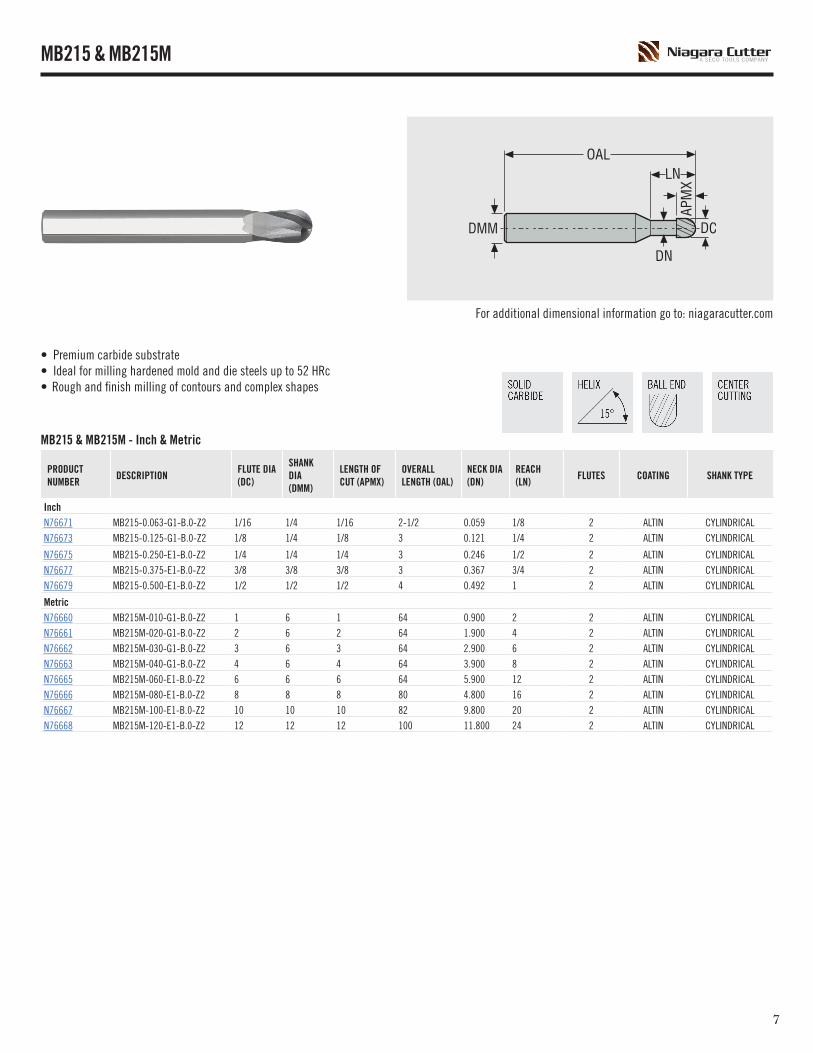
MB215 & MB215M - Inch & Metric
PRODUCT NUMBER
DESCRIPTION FLUTE DIA (DC)
SHANK DIA (DMM)
LENGTH OF CUT (APMX)
OVERALL LENGTH (OAL)
NECK DIA (DN)
REACH (LN)
FLUTES COATING SHANK TYPE
InchN76671 MB215-0.063-G1-B.0-Z2 1/16 1/4 1/16 2-1/2 0.059 1/8 2 ALTIN CYLINDRICALN76673 MB215-0.125-G1-B.0-Z2 1/8 1/4 1/8 3 0.121 1/4 2 ALTIN CYLINDRICAL
N76675 MB215-0.250-E1-B.0-Z2 1/4 1/4 1/4 3 0.246 1/2 2 ALTIN CYLINDRICALN76677 MB215-0.375-E1-B.0-Z2 3/8 3/8 3/8 3 0.367 3/4 2 ALTIN CYLINDRICALN76679 MB215-0.500-E1-B.0-Z2 1/2 1/2 1/2 4 0.492 1 2 ALTIN CYLINDRICAL
MetricN76660 MB215M-010-G1-B.0-Z2 1 6 1 64 0.900 2 2 ALTIN CYLINDRICALN76661 MB215M-020-G1-B.0-Z2 2 6 2 64 1.900 4 2 ALTIN CYLINDRICALN76662 MB215M-030-G1-B.0-Z2 3 6 3 64 2.900 6 2 ALTIN CYLINDRICALN76663 MB215M-040-G1-B.0-Z2 4 6 4 64 3.900 8 2 ALTIN CYLINDRICALN76665 MB215M-060-E1-B.0-Z2 6 6 6 64 5.900 12 2 ALTIN CYLINDRICALN76666 MB215M-080-E1-B.0-Z2 8 8 8 80 4.800 16 2 ALTIN CYLINDRICALN76667 MB215M-100-E1-B.0-Z2 10 10 10 82 9.800 20 2 ALTIN CYLINDRICALN76668 MB215M-120-E1-B.0-Z2 12 12 12 100 11.800 24 2 ALTIN CYLINDRICAL
• Premium carbide substrate• Ideal for milling hardened mold and die steels up to 52 HRc• Rough and finish milling of contours and complex shapes
MB215 & MB215M
For additional dimensional information go to: niagaracutter.com

98
• Strong end tooth design• Ideal for hardened steels (>48 HRc) and nickel based superalloys such as Inconel• Edge preparation for increased cutting edge strength• 2° back taper with reduced neck diameter for workpiece clearance
MZN410R & MZN510R - Inch
PRODUCT NUMBER DESCRIPTION
FLUTE DIA (DC)
SHANK DIA (DMM)
LENGTH OF CUT (APMX)
OVERALL LENGTH (OAL)
NECK DIA (DN)
REACH)(LN) FLUTES
RADIUS(RE) COATING SHANK TYPE
MZN410RInchN00305 MZN410R-0.125-J1-R030.0-Z4 1/8 1/4 0.030 2-1/2 0.112 0.375 4 0.030 ALTIN CYLINDRICAL
N00001 MZN410R-0.125-J2-R030.0-Z4 1/8 1/4 0.030 2-1/2 0.112 0.625 4 0.030 ALTIN CYLINDRICAL
N00002 MZN410R-0.188-J1-R050.0-Z4 3/16 1/4 0.050 2-1/2 0.172 0.562 4 0.050 ALTIN CYLINDRICAL
N00003 MZN410R-0.188-J2-R050.0-Z4 3/16 1/4 0.050 2-1/2 0.172 0.937 4 0.050 ALTIN CYLINDRICAL
N00004 MZN410R-0.250-E1-R060.0-Z4 1/4 1/4 0.060 2-1/2 0.230 0.750 4 0.060 ALTIN CYLINDRICAL
N00005 MZN410R-0.250-E2-R060.0-Z4 1/4 1/4 0.060 2-1/2 0.230 1.250 4 0.060 ALTIN CYLINDRICAL
N00006 MZN410R-0.313-G1-R080.0-Z4 5/16 3/8 0.080 3 0.290 0.750 4 0.080 ALTIN CYLINDRICAL
N00007 MZN410R-0.313-G2-R080.0-Z4 5/16 3/8 0.080 3 0.290 1.250 4 0.080 ALTIN CYLINDRICAL
N00008 MZN410R-0.375-E1-R080.0-Z4 3/8 3/8 0.080 3 0.348 1.125 4 0.080 ALTIN CYLINDRICAL
N00010 MZN410R-0.375-E3-R080.0-Z4 3/8 3/8 0.080 3 0.348 1.875 4 0.080 ALTIN CYLINDRICAL
N00011 MZN410R-0.500-E1-R120.0-Z4 1/2 1/2 0.120 4 0.468 1.500 4 0.120 ALTIN CYLINDRICAL
MZN510R
InchN00009 MZN510R-0.375-E2-R080.0-Z5 3/8 3/8 0.080 3 0.348 1.125 5 0.080 ALTIN CYLINDRICALN00012 MZN510R-0.500-E2-R120.0-Z5 1/2 1/2 0.120 4 0.468 1.500 5 0.120 ALTIN CYLINDRICALN00013 MZN510R-0.625-E1-R120.0-Z5 5/8 5/8 0.120 4 0.584 1.875 5 0.120 ALTIN CYLINDRICAL
MZN410R & MZN510R
For additional dimensional information go to: niagaracutter.com

98
• Strong end tooth design• Ideal for hardened steels (>48 HRc) and nickel based superalloys such as Inconel• Edge preparation for increased cutting edge strength• 2° back taper with reduced neck diameter for workpiece clearance
MZN410RM & MZN510RM - Metric
PRODUCT NUMBER DESCRIPTION
FLUTE DIA (DC)
SHANK DIA (DMM)
LENGTH OF CUT (APMX)
OVERALL LENGTH (OAL)
NECK DIA (DN)
REACH)(LN) FLUTES
RADIUS(RE) COATING SHANK TYPE
MZN410RMMetric03169565 MZN410RM-020-G2-R050.0-Z4 2 6 0.5 50 1.80 4 4 0.50 ALTIN CYLINDRICAL03169573 MZN410RM-020-G4-R050.0-Z4 2 6 0.5 55 1.80 8 4 0.50 ALTIN CYLINDRICAL03169566 MZN410RM-030-G2-R075.0-Z4 3 6 0.75 50 2.70 6 4 0.75 ALTIN CYLINDRICAL03169574 MZN410RM-030-G4-R075.0-Z4 3 6 0.75 55 2.70 12 4 0.75 ALTIN CYLINDRICAL03169567 MZN410RM-040-G2-R100.0-Z4 4 6 1 50 3.60 8 4 1.00 ALTIN CYLINDRICAL03169575 MZN410RM-040-G4-R100.0-Z4 4 6 1 65 3.60 16 4 1.00 ALTIN CYLINDRICAL03169568 MZN410RM-060-E2-R150.0-Z4 6 6 1.5 55 5.40 12 4 1.50 ALTIN CYLINDRICAL03169576 MZN410RM-060-E4-R150.0-Z4 6 6 1.5 65 5.40 24 4 1.50 ALTIN CYLINDRICAL03169569 MZN410RM-080-E2-R200.0-Z4 8 8 2 60 7.30 16 4 2.00 ALTIN CYLINDRICAL03169577 MZN410RM-080-E4-R200.0-Z4 8 8 2 75 7.30 32 4 2.00 ALTIN CYLINDRICAL03169570 MZN410RM-100-E2-R200.0-Z4 10 10 2 70 9.20 20 4 2.00 ALTIN CYLINDRICAL03169578 MZN410RM-100-E4-R200.0-Z4 10 10 2 100 9.20 40 4 2.00 ALTIN CYLINDRICAL03169579 MZN410RM-120-E4-R300.0-Z4 12 12 3 100 11.00 48 4 3.00 ALTIN CYLINDRICAL
MZN510RM
Metric03169571 MZN510RM-100-E2-R200.0-Z5 10 10 2 70 9.20 20 5 2.00 ALTIN CYLINDRICAL03169572 MZN510RM-120-E2-R300.0-Z5 12 12 3 75 11.00 24 5 3.00 ALTIN CYLINDRICAL
MZN410RM & MZN510RM
For additional dimensional information go to: niagaracutter.com

1110
MZ645 & MZ645R - Inch
PRODUCT NUMBER DESCRIPTION FLUTE
DIA (DC)SHANK DIA (DMM)
LENGTH OF CUT (APMX)
OVERALL LENGTH (OAL) FLUTES RADIUS
(RE) COATING SHANK TYPE
MZ645InchN76617 MZ645-0.125-F3-S.0-Z6 1/8 1/4 3/8 3 6 - ALTIN CYLINDRICALN76619 MZ645-0.188-F3-S.0-Z6 3/16 1/4 1/2 3 6 - ALTIN CYLINDRICAL
N76621 MZ645-0.250-D3-S.0-Z6 1/4 1/4 5/8 3 6 - ALTIN CYLINDRICALN76623 MZ645-0.313-D2-S.0-Z6 5/16 5/16 3/4 3 6 - ALTIN CYLINDRICALN76625 MZ645-0.375-D3-S.0-Z6 3/8 3/8 1 3 6 - ALTIN CYLINDRICAL
N76627 MZ645-0.500-D2-S.0-Z6 1/2 1/2 1-1/8 4 6 - ALTIN CYLINDRICAL
MZ645RInchN76616 MZ645R-0.125-F3-R020.0-Z6 1/8 1/4 3/8 3 6 0.020 ALTIN CYLINDRICALN76618 MZ645R-0.188-F3-R020.0-Z6 3/16 1/4 1/2 3 6 0.020 ALTIN CYLINDRICALN76620 MZ645R-0.250-D3-R020.0-Z6 1/4 1/4 5/8 3 6 0.020 ALTIN CYLINDRICALN76622 MZ645R-0.313-D2-R020.0-Z6 5/16 5/16 3/4 3 6 0.020 ALTIN CYLINDRICALN76624 MZ645R-0.375-D3-R020.0-Z6 3/8 3/8 1 3 6 0.020 ALTIN CYLINDRICALN76626 MZ645R-0.500-D2-R030.0-Z6 1/2 1/2 1-1/8 4 6 0.030 ALTIN CYLINDRICAL
• Ideal for peripheral milling of hard steels up to 62 HRc
MZ645 & MZ645R

1110
SOLID END MILLING - CUTTING DATA
MBZ215 - START VALUES - InchCOPY MILLING - ROUGHING
ISOGROUP
SMGap x Dc (max)
ae x Dc(max)
vc(sf / min)
Zn = 2
1/16 1/8 3/16 1/4 3/8 1/2
H
M / A / D7a
(48-56 HRc)0.10 0.30
560n (rev/min) 33960 17110 11380 8560 5700 4280
fz (in) 0.0012 0.0024 0.0036 0.0048 0.0071 0.0095
460 - 660 vf (in/min) 81 81 81 81 81 81
M / A / D7b
(56-62 HRc)0.07 0.25
390n (rev/min) 23650 11920 7920 5960 3970 2980
fz (in) 0.0009 0.0019 0.0028 0.0038 0.0056 0.0075
330 - 460 vf (in/min) 45 45 45 45 45 45
M / A / D7c
(62-65 HRc)0.05 0.20
260n (rev/min) 15770 7950 5280 3970 2650 1990
fz (in) 0.0008 0.0016 0.0024 0.0033 0.0049 0.0065
200 - 330 vf (in/min) 26 26 26 26 26 26
M / A / D7d
(>65 HRc)0.04 0.15
160n (rev/min) 9700 4890 3250 2440 1630 1220
fz (in) 0.0007 0.0014 0.0021 0.0028 0.0041 0.0055
130 - 200 vf (in/min) 13 13 13 13 13 13
K
E12 - 13
0.15 0.30820
n (rev/min) 49720 25060 16660 12530 8350 6260
fz (in) 0.0008 0.0016 0.0024 0.0033 0.0049 0.0065
660 - 980 vf (in/min) 81 81 81 81 81 81
E14 - 15
0.14 0.20660
n (rev/min) 40020 20170 13410 10080 6720 5040
fz (in) 0.0008 0.0015 0.0023 0.0030 0.0045 0.0060
490 - 820 vf (in/min) 61 61 61 61 61 61
COPY MILLING - FINISHING
ISOGROUP
SMGap x Dc (max)
ae x Dc(max)
vc(sf / min)
Zn = 2
1/16 1/8 3/16 1/4 3/8 1/2
H
M / A / D7a
(48-56 HRc)0.02 0.01
920n (rev/min) 55780 28120 18690 14060 9370 7030
fz (in) 0.0008 0.0016 0.0024 0.0033 0.0049 0.0065
690 - 1150 vf (in/min) 91 91 91 91 91 91
M / A / D7b
(56-62 HRc)0.02 0.01
560n (rev/min) 33960 17110 11380 8560 5700 4280
fz (in) 0.0008 0.0015 0.0023 0.0030 0.0045 0.0060
430 - 690 vf (in/min) 51 51 51 51 51 51
M / A / D7c
(62-65 HRc)0.01 0.01
360n (rev/min) 21830 11000 7310 5500 3670 2750
fz (in) 0.0006 0.0013 0.0019 0.0025 0.0038 0.0050
300 - 430 vf (in/min) 28 28 28 28 28 28
M / A / D7d
(>65 HRc)0.01 0.01
260n (rev/min) 15770 7950 5280 3970 2650 1990
fz (in) 0.0006 0.0013 0.0019 0.0025 0.0038 0.0050
230 - 300 vf (in/min) 20 20 20 20 20 20
K
E12 - 13
0.03 0.021130
n (rev/min) 68520 34530 22960 17270 11510 8630
fz (in) 0.0009 0.0019 0.0028 0.0038 0.0056 0.0075
1050 - 1210 vf (in/min) 129 129 129 129 129 129
E14 - 15
0.02 0.02950
n (rev/min) 57600 29030 19300 14520 9680 7260
fz (in) 0.0009 0.0018 0.0026 0.0035 0.0053 0.0070
870 - 1030 vf (in/min) 102 102 102 102 102 102
SMG = Seco Material Groupn (rev/min) = RPM fz (in) = Feed/tooth vf (in/min) = Feed ratevc (sf/min) = Surface feet/min ap/Dc = % of diameter ae/Dc = % of diameter
A = Air D = Dry E = Emulsion (flood coolant) M = MistAll cutting data are start values. All cutting data is in inch values.

1312
MBZ215M - UP TO 4 X D - START VALUES - InchCOPY MILLING - ROUGHING
ISOGROUP
SMGap x Dc (max)
ae x Dc(max)
vc(sf / min)
Zn = 2
0.5 0.8 1 1.5 2 2.5 3 3.5 4 5 6 8 10 12
H
M / A / D7a
(48-56 HRc)
0.10 0.30560
n (rev/min) 108663 67914 54332 36221 27166 21733 18111 15523 13583 10866 9055 6791 5433 4528
fz (in) 0.0004 0.0006 0.0007 0.0011 0.0015 0.0019 0.0022 0.0026 0.0030 0.0037 0.0045 0.0060 0.0075 0.0090
460 - 660 vf (in/min) 81 81 81 81 81 81 81 81 81 81 81 81 81 81
M / A / D7b
(56-62 HRc)
0.07 0.25390
n (rev/min) 75676 47298 37838 25225 18919 15135 12613 10811 9460 7568 6306 4730 3784 3153
fz (in) 0.0003 0.0005 0.0006 0.0009 0.0012 0.0015 0.0018 0.0021 0.0024 0.0030 0.0035 0.0047 0.0059 0.0071
330 - 460 vf (in/min) 45 45 45 45 45 45 45 45 45 45 45 45 45 45
M / A / D7c
(62-65 HRc)
0.05 0.20260
n (rev/min) 50451 31532 25225 16817 12613 10090 8408 7207 6306 5045 4204 3153 2523 2102
fz (in) 0.0003 0.0004 0.0005 0.0008 0.0010 0.0013 0.0015 0.0018 0.0020 0.0026 0.0031 0.0041 0.0051 0.0061
200 - 330 vf (in/min) 26 26 26 26 26 26 26 26 26 26 26 26 26 26
M / A / D7d
(>65 HRc)0.04 0.15
160n (rev/min) 31047 19404 15523 10349 7762 6209 5174 4435 3881 3105 2587 1940 1552 1294
fz (in) 0.0002 0.0003 0.0004 0.0006 0.0009 0.0011 0.0013 0.0015 0.0017 0.0022 0.0026 0.0035 0.0043 0.0052
130 - 200 vf (in/min) 13 13 13 13 13 13 13 13 13 13 13 13 13 13
K
E12 - 13
0.15 0.30820
n (rev/min) 159114 99446 79557 53038 39778 31823 26519 22731 19889 15911 13259 9945 7956 6630
fz (in) 0.0003 0.0004 0.0005 0.0008 0.0010 0.0013 0.0015 0.0018 0.0020 0.0026 0.0031 0.0041 0.0051 0.0061
660 - 980 vf (in/min) 81 81 81 81 81 81 81 81 81 81 81 81 81 81
E14 - 15
0.14 0.20660
n (rev/min) 128067 80042 64034 42689 32017 25613 21345 18295 16008 12807 10672 8004 6403 5336
fz (in) 0.0002 0.0004 0.0005 0.0007 0.0009 0.0012 0.0014 0.0017 0.0019 0.0024 0.0028 0.0038 0.0047 0.0057
490 - 820 vf (in/min) 61 61 61 61 61 61 61 61 61 61 61 61 61 61
COPY MILLING - FINISHING
ISOGROUP
SMGap x Dc (max)
ae x Dc(max)
vc(sf / min)
Zn = 2
0.5 0.8 1 1.5 2 2.5 3 3.5 4 5 6 8 10 12
H
M / A / D7a
(48-56 HRc)
0.02 0.01920
n (rev/min) 178518 111574 89259 59506 44629 35704 29753 25503 22315 17852 14876 11157 8926 7438
fz (in) 0.0003 0.0004 0.0005 0.0008 0.0010 0.0013 0.0015 0.0018 0.0020 0.0026 0.0031 0.0041 0.0051 0.0061
690 - 1150 vf (in/min) 91 91 91 91 91 91 91 91 91 91 91 91 91 91
M / A / D7b
(56-62 HRc)
0.02 0.01560
n (rev/min) 108663 67914 54332 36221 27166 21733 18111 15523 13583 10866 9055 6791 5433 4528
fz (in) 0.0002 0.0004 0.0005 0.0007 0.0009 0.0012 0.0014 0.0017 0.0019 0.0024 0.0028 0.0038 0.0047 0.0057
430 - 690 vf (in/min) 51 51 51 51 51 51 51 51 51 51 51 51 51 51
M / A / D7c
(62-65 HRc)
0.01 0.01360
n (rev/min) 69855 43659 34927 23285 17464 13971 11642 9979 8732 6985 5821 4366 3493 2911
fz (in) 0.0002 0.0003 0.0004 0.0006 0.0008 0.0010 0.0012 0.0014 0.0016 0.0020 0.0024 0.0031 0.0039 0.0047
300 - 430 vf (in/min) 28 28 28 28 28 28 28 28 28 28 28 28 28 28
M / A / D7d
(>65 HRc)0.01 0.01
260n (rev/min) 50451 31532 25225 16817 12613 10090 8408 7207 6306 5045 4204 3153 2523 2102
fz (in) 0.0002 0.0003 0.0004 0.0006 0.0008 0.0010 0.0012 0.0014 0.0016 0.0020 0.0024 0.0031 0.0039 0.0047
230 - 300 vf (in/min) 20 20 20 20 20 20 20 20 20 20 20 20 20 20
K
E12 - 13
0.03 0.021130
n (rev/min) 219267 137042 109633 73089 54817 43853 36544 31324 27408 21927 18272 13704 10963 9136
fz (in) 0.0003 0.0005 0.0006 0.0009 0.0012 0.0015 0.0018 0.0021 0.0024 0.0030 0.0035 0.0047 0.0059 0.0071
1050 - 1210 vf (in/min) 129 129 129 129 129 129 129 129 129 129 129 129 129 129
E14 - 15
0.02 0.02950
n (rev/min) 184339 115212 92170 61446 46085 36868 30723 26334 23042 18434 15362 11521 9217 7681
fz (in) 0.0003 0.0004 0.0006 0.0008 0.0011 0.0014 0.0017 0.0019 0.0022 0.0028 0.0033 0.0044 0.0055 0.0066
870 - 1030 vf (in/min) 102 102 102 102 102 102 102 102 102 102 102 102 102 102
SOLID END MILLING - CUTTING DATA
SMG = Seco Material Groupn (rev/min) = RPM fz (in) = Feed/tooth vf (in/min) = Feed ratevc (sf/min) = Surface feet/min ap/Dc = % of diameter ae/Dc = % of diameter
A = Air D = Dry E = Emulsion (flood coolant) M = MistAll cutting data are start values. All cutting data is in inch values.

1312
MBZ215M - 6 X D - START VALUES - InchCOPY MILLING - ROUGHING
ISOGROUP
SMGap x Dc (max)
ae x Dc(max)
vc(sf / min)
Zn = 2
0.5 0.8 1 1.5 2 2.5 3 4 5 6 8 10
H
M / A / D7a
(48-56 HRc)0.04 0.23
560n (rev/min) 108663 67914 54332 36221 27166 21733 18111 13583 10866 9055 6791 5433
fz (in) 0.0003 0.0005 0.0007 0.0010 0.0013 0.0017 0.0020 0.0027 0.0034 0.0040 0.0054 0.0067
460 - 660 vf (in/min) 73 73 73 73 73 73 73 73 73 73 73 73
M / A / D7b
(56-62 HRc)0.03 0.19
390n (rev/min) 75676 47298 37838 25225 18919 15135 12613 9460 7568 6306 4730 3784
fz (in) 0.0003 0.0004 0.0005 0.0008 0.0011 0.0013 0.0016 0.0021 0.0027 0.0032 0.0043 0.0053
330 - 460 vf (in/min) 40 40 40 40 40 40 40 40 40 40 40 40
M / A / D7c
(62-65 HRc)0.02 0.15
260n (rev/min) 50451 31532 25225 16817 12613 10090 8408 6306 5045 4204 3153 2523
fz (in) 0.0002 0.0004 0.0005 0.0007 0.0009 0.0012 0.0014 0.0018 0.0023 0.0028 0.0037 0.0046
200 - 330 vf (in/min) 23 23 23 23 23 23 23 23 23 23 23 23
M / A / D7d
(>65 HRc)0.016 0.11
160n (rev/min) 31047 19404 15523 10349 7762 6209 5174 3881 3105 2587 1940 1552
fz (in) 0.0002 0.0003 0.0004 0.0006 0.0008 0.0010 0.0012 0.0016 0.0019 0.0023 0.0031 0.0039
130 - 200 vf (in/min) 12 12 12 12 12 12 12 12 12 12 12 12
K
E12 - 13
0.06 0.23820
n (rev/min) 159114 99446 79557 53038 39778 31823 26519 19889 15911 13259 9945 7956
fz (in) 0.0002 0.0004 0.0005 0.0007 0.0009 0.0012 0.0014 0.0018 0.0023 0.0028 0.0037 0.0046
660 - 980 vf (in/min) 73 73 73 73 73 73 73 73 73 73 73 73
E14 - 15
0.05 0.15660
n (rev/min) 128067 80042 64034 42689 32017 25613 21345 16008 12807 10672 8004 6403
fz (in) 0.0002 0.0003 0.0004 0.0006 0.0009 0.0011 0.0013 0.0017 0.0021 0.0026 0.0034 0.0043
490 - 820 vf (in/min) 54 54 54 54 54 54 54 54 54 54 54 54
COPY MILLING - FINISHING
ISOGROUP
SMGap x Dc (max)
ae x Dc(max)
vc(sf / min)
Zn = 2
0.5 0.8 1 1.5 2 2.5 3 4 5 6 8 10
H
M / A / D7a
(48-56 HRc)0.01 0.01
920n (rev/min) 178518 111574 89259 59506 44629 35704 29753 22315 17852 14876 11157 8926
fz (in) 0.0002 0.0004 0.0005 0.0007 0.0009 0.0012 0.0014 0.0018 0.0023 0.0028 0.0037 0.0046
690 - 1150 vf (in/min) 82 82 82 82 82 82 82 82 82 82 82 82
M / A / D7b
(56-62 HRc)0.01 0.01
560n (rev/min) 108663 67914 54332 36221 27166 21733 18111 13583 10866 9055 6791 5433
fz (in) 0.0002 0.0003 0.0004 0.0006 0.0009 0.0011 0.0013 0.0017 0.0021 0.0026 0.0034 0.0043
430 - 690 vf (in/min) 46 46 46 46 46 46 46 46 46 46 46 46
M / A / D7c
(62-65 HRc)0.01 0.01
360n (rev/min) 69855 43659 34927 23285 17464 13971 11642 8732 6985 5821 4366 3493
fz (in) 0.0002 0.0003 0.0004 0.0005 0.0007 0.0009 0.0011 0.0014 0.0018 0.0021 0.0028 0.0035
300 - 430 vf (in/min) 25 25 25 25 25 25 25 25 25 25 25 25
M / A / D7d
(>65 HRc)0.01 0.01
260n (rev/min) 50451 31532 25225 16817 12613 10090 8408 6306 5045 4204 3153 2523
fz (in) 0.0002 0.0003 0.0004 0.0005 0.0007 0.0009 0.0011 0.0014 0.0018 0.0021 0.0028 0.0035
230 - 300 vf (in/min) 18 18 18 18 18 18 18 18 18 18 18 18
K
E12 - 13
0.01 0.021130
n (rev/min) 219267 137042 109633 73089 54817 43853 36544 27408 21927 18272 13704 10963
fz (in) 0.0003 0.0004 0.0005 0.0008 0.0011 0.0013 0.0016 0.0021 0.0027 0.0032 0.0043 0.0053
1050 - 1210 vf (in/min) 117 117 117 117 117 117 117 117 117 117 117 117
E14 - 15
0.01 0.02950
n (rev/min) 184339 115212 92170 61446 46085 36868 30723 23042 18434 15362 11521 9217
fz (in) 0.0002 0.0004 0.0005 0.0007 0.0010 0.0012 0.0015 0.0020 0.0025 0.0030 0.0040 0.0050
870 - 1030 vf (in/min) 91 91 91 91 91 91 91 91 91 91 91 91
SOLID END MILLING - CUTTING DATA
SMG = Seco Material Groupn (rev/min) = RPM fz (in) = Feed/tooth vf (in/min) = Feed ratevc (sf/min) = Surface feet/min ap/Dc = % of diameter ae/Dc = % of diameter
A = Air D = Dry E = Emulsion (flood coolant) M = MistAll cutting data are start values. All cutting data is in inch values.

1514
MBZ215M - 6 X D PLUS - START VALUES - InchCOPY MILLING - ROUGHING
ISOGROUP
SMGap x Dc (max)
ae x Dc(max)
vc(sf / min)
Zn = 2
1 2 3 4 5 6 8
H
M / A / D7a
(48-56 HRc)0.01 0.17
560n (rev/min) 54332 27166 18111 13583 10866 9055 6791
fz (in) 0.0006 0.0012 0.0018 0.0024 0.0030 0.0036 0.0048
460 - 660 vf (in/min) 66 66 66 66 66 66 66
M / A / D7b
(56-62 HRc)0.007 0.14
390n (rev/min) 37838 18919 12613 9460 7568 6306 4730
fz (in) 0.0005 0.0010 0.0014 0.0019 0.0024 0.0029 0.0038
330 - 460 vf (in/min) 36 36 36 36 36 36 36
M / A / D7c
(62-65 HRc)0.005 0.11
260n (rev/min) 25225 12613 8408 6306 5045 4204 3153
fz (in) 0.0004 0.0008 0.0012 0.0017 0.0021 0.0025 0.0033
200 - 330 vf (in/min) 21 21 21 21 21 21 21
M / A / D7d
(>65 HRc)0.004 0.08
160n (rev/min) 15523 7762 5174 3881 3105 2587 1940
fz (in) 0.0004 0.0007 0.0011 0.0014 0.0018 0.0021 0.0028
130 - 200 vf (in/min) 11 11 11 11 11 11 11
K
E12 - 13
0.015 0.17820
n (rev/min) 79557 39778 26519 19889 15911 13259 9945
fz (in) 0.0004 0.0008 0.0012 0.0017 0.0021 0.0025 0.0033
660 - 980 vf (in/min) 66 66 66 66 66 66 66
E14 - 15
0.014 0.11660
n (rev/min) 64034 32017 21345 16008 12807 10672 8004
fz (in) 0.0004 0.0008 0.0011 0.0015 0.0019 0.0023 0.0031
490 - 820 vf (in/min) 49 49 49 49 49 49 49
COPY MILLING - FINISHING
ISOGROUP
SMGap x Dc (max)
ae x Dc(max)
vc(sf / min)
Zn = 2
1 2 3 4 5 6 8
H
M / A / D7a
(48-56 HRc)0.010 0.010
920n (rev/min) 89259 44629 29753 22315 17852 14876 11157
fz (in) 0.0004 0.0008 0.0012 0.0017 0.0021 0.0025 0.0033
690 - 1150 vf (in/min) 74 74 74 74 74 74 74
M / A / D7b
(56-62 HRc)0.010 0.010
560n (rev/min) 54332 27166 18111 13583 10866 9055 6791
fz (in) 0.0004 0.0008 0.0011 0.0015 0.0019 0.0023 0.0031
430 - 690 vf (in/min) 42 42 42 42 42 42 42
M / A / D7c
(62-65 HRc)0.010 0.010
360n (rev/min) 34927 17464 11642 8732 6985 5821 4366
fz (in) 0.0003 0.0006 0.0010 0.0013 0.0016 0.0019 0.0026
300 - 430 vf (in/min) 22 22 22 22 22 22 22
M / A / D7d
(>65 HRc)0.010 0.010
260n (rev/min) 25225 12613 8408 6306 5045 4204 3153
fz (in) 0.0003 0.0006 0.0010 0.0013 0.0016 0.0019 0.0026
230 - 300 vf (in/min) 16 16 16 16 16 16 16
K
E12 - 13
0.030 0.0201130
n (rev/min) 109633 54817 36544 27408 21927 18272 13704
fz (in) 0.0005 0.0010 0.0014 0.0019 0.0024 0.0029 0.0038
1050 - 1210 vf (in/min) 105 105 105 105 105 105 105
E14 - 15
0.020 0.020950
n (rev/min) 92170 46085 30723 23042 18434 15362 11521
fz (in) 0.0004 0.0009 0.0013 0.0018 0.0022 0.0027 0.0036
870 - 1030 vf (in/min) 82 82 82 82 82 82 82
SOLID END MILLING - CUTTING DATA
SMG = Seco Material Groupn (rev/min) = RPM fz (in) = Feed/tooth vf (in/min) = Feed ratevc (sf/min) = Surface feet/min ap/Dc = % of diameter ae/Dc = % of diameter
A = Air D = Dry E = Emulsion (flood coolant) M = MistAll cutting data are start values. All cutting data is in inch values.

1514
SOLID END MILLING - CUTTING DATA
MB215 - START VALUES - InchCOPY MILLING - ROUGHING
ISOGROUP
SMGap x Dc (max)
ae x Dc(max)
vc(sf / min) 1/16 1/8 3/16 1/4 3/8 1/2
PE
5 - 60.11 0.31
710n (rev/min) 43050 21700 14430 10850 7230 5420
fz (in) 0.0011 0.0023 0.0034 0.0045 0.0068 0.0090
610 - 800 vf (in/min) 98 98 98 98 98 98
HM / A / D
7a(48-52 HRc)
0.10 0.30560
n (rev/min) 33960 17110 11380 8560 5700 4280
fz (in) 0.0012 0.0024 0.0036 0.0048 0.0071 0.0095
460 - 660 vf (in/min) 81 81 81 81 81 81
COPY MILLING - FINISHING
ISOGROUP
SMGap x Dc (max)
ae x Dc(max)
vc(sf / min) 1/16 1/8 3/16 1/4 3/8 1/2
PE
5 - 60.02 0.02
1070n (rev/min) 64880 32700 21740 16350 10900 8170
fz (in) 0.0008 0.0016 0.0024 0.0033 0.0049 0.0065
840 - 1300 vf (in/min) 106 106 106 106 106 106
HM / A / D
7a(48-52 HRc)
0.02 0.01920
n (rev/min) 55780 28120 18690 14060 9370 7030
fz (in) 0.0008 0.0016 0.0024 0.0033 0.0049 0.0065
690 - 1150 vf (in/min) 91 91 91 91 91 91
MB215M - START VALUES - InchCOPY MILLING - ROUGHING
ISOGROUP
SMGap x Dc (max)
ae x Dc(max)
vc(m / min)
Zn = 2
1 2 3 4 5 6 8 10 12
PE
5 - 60.10 0.30
710n (rev/min) 68885 34442 22962 17221 13777 11481 8611 6888 5740
fz (in) 0.0007 0.0014 0.0021 0.0028 0.0035 0.0043 0.0057 0.0071 0.0085
610 - 800 vf (in/min) 98 98 98 98 98 98 98 98 98
HM / A / D
7a(48-52HRc)
0.10 0.30560
n (rev/min) 54332 27166 18111 13583 10866 9055 6791 5433 4528
fz (in) 0.0007 0.0015 0.0022 0.0030 0.0037 0.0045 0.0060 0.0075 0.0090
460 - 660 vf (in/min) 81 81 81 81 81 81 81 81 81
COPY MILLING - FINISHING
ISOGROUP SMG
ap x Dc (max)
ae x Dc(max)
vc(m / min)
Zn = 2
1 2 3 4 5 6 8 10 12
PE
5 - 60.02 0.02
1070n (rev/min) 103812 51906 34604 25953 20762 17302 12977 10381 8651
fz (in) 0.0005 0.0010 0.0015 0.0020 0.0026 0.0031 0.0041 0.0051 0.0061
840 - 1300 vf (in/min) 106 106 106 106 106 106 106 106 106
HM / A / D
7a(48-52HRc)
0.02 0.01920
n (rev/min) 89259 44629 29753 22315 17852 14876 11157 8926 7438
fz (in) 0.0005 0.0010 0.0015 0.0020 0.0026 0.0031 0.0041 0.0051 0.0061
690 - 1150 vf (in/min) 91 91 91 91 91 91 91 91 91
SMG = Seco Material Groupn (rev/min) = RPM fz (in) = Feed/tooth vf (in/min) = Feed ratevc (sf/min) = Surface feet/min ap/Dc = % of diameter ae/Dc = % of diameter
A = Air D = Dry E = Emulsion (flood coolant) M = MistAll cutting data are start values. All cutting data is in inch values.

1716
SOLID END MILLING - CUTTING DATA
MZN410R / MZN510R - 2 X D START VALUES - InchSLOTTING
ISOGROUP
SMGae x Dc
(max)vc
(sf / min)
Zn = 4 Zn = 5
1/8 3/16 1/4 5/16 3/8 1/2 5/8 3/8 1/2 5/8
PE / M / A
5 - 61.00
740n (rev/min) 22614 15076 11307 9046 7538 5654 4523 7538 5654 4523
fz (in) 0.0031 0.0047 0.0063 0.0078 0.0094 0.0125 0.0156 0.0094 0.0125 0.0156
690 - 790vf (in/min) 283 283 283 283 283 283 283 353 353 353
Max Ap 0.008 0.012 0.014 0.018 0.020 0.022 0.024 0.022 0.022 0.024
H
M / A / D7a
(48-56 HRc)
1.00
440n (rev/min) 13446 8964 6723 5379 4482 3362 2689 4482 3362 2689
fz (in) 0.0031 0.0047 0.0063 0.0078 0.0094 0.0125 0.0156 0.0094 0.0125 0.0156
390 - 490vf (in/min) 168 168 168 168 168 168 168 210 210 210
Max Ap 0.008 0.012 0.014 0.018 0.020 0.022 0.024 0.022 0.022 0.024
M / A / D7b
(56-62 HRc)
1.00
230n (rev/min) 7029 4686 3514 2812 2343 1757 1406 2343 1757 1406
fz (in) 0.0025 0.0038 0.005 0.0063 0.0075 0.01 0.0125 0.0075 0.01 0.0125
200 - 260vf (in/min) 70 70 70 70 70 70 70 88 88 88
Max Ap 0.004 0.004 0.007 0.007 0.010 0.011 0.012 0.011 0.011 0.012
K
E / M / A12 - 13
1.00
570n (rev/min) 17419 11613 8710 6968 5806 4355 3484 5806 4355 3484
fz (in) 0.0030 0.0045 0.0060 0.0075 0.0090 0.0120 0.0150 0.0090 0.0120 0.0150
490 - 650vf (in/min) 209 209 209 209 209 209 209 261 261 261
Max Ap 0.008 0.012 0.014 0.016 0.018 0.020 0.022 0.020 0.020 0.022
E / M / A14 - 15
1.00
410n (rev/min) 12530 8353 6265 5012 4177 t3132 2506 4177 3132 2506
fz (in) 0.0023 0.0034 0.0045 0.0056 0.0068 0.0090 0.0113 0.0068 0.0090 0.0113
330 - 490vf (in/min) 113 113 113 113 113 113 113 141 141 141
Max Ap 0.008 0.012 0.014 0.016 0.018 0.020 0.022 0.020 0.020 0.022
SE21
1.00
100n (rev/min) 3056 2037 1528 1222 1019 764 611 1019 764 611
fz (in) 0.0010 0.0015 0.0021 0.0026 0.0031 0.0041 0.0051 0.0031 0.0041 0.0051
90 - 110vf (in/min) 13 13 13 13 13 13 13 16 16 16
Max Ap 0.004 0.006 0.007 0.008 0.010 0.015 0.015 0.015 0.015 0.015
SMG = Seco Material Groupn (rev/min) = RPM fz (in) = Feed/tooth vf (in/min) = Feed ratevc (sf/min) = Surface feet/min Max Ap = Max depth of cut ae/Dc = % of diameter
A = Air D = Dry E = Emulsion (flood coolant) M = MistAll cutting data are start values. All cutting data is in inch values.
1716
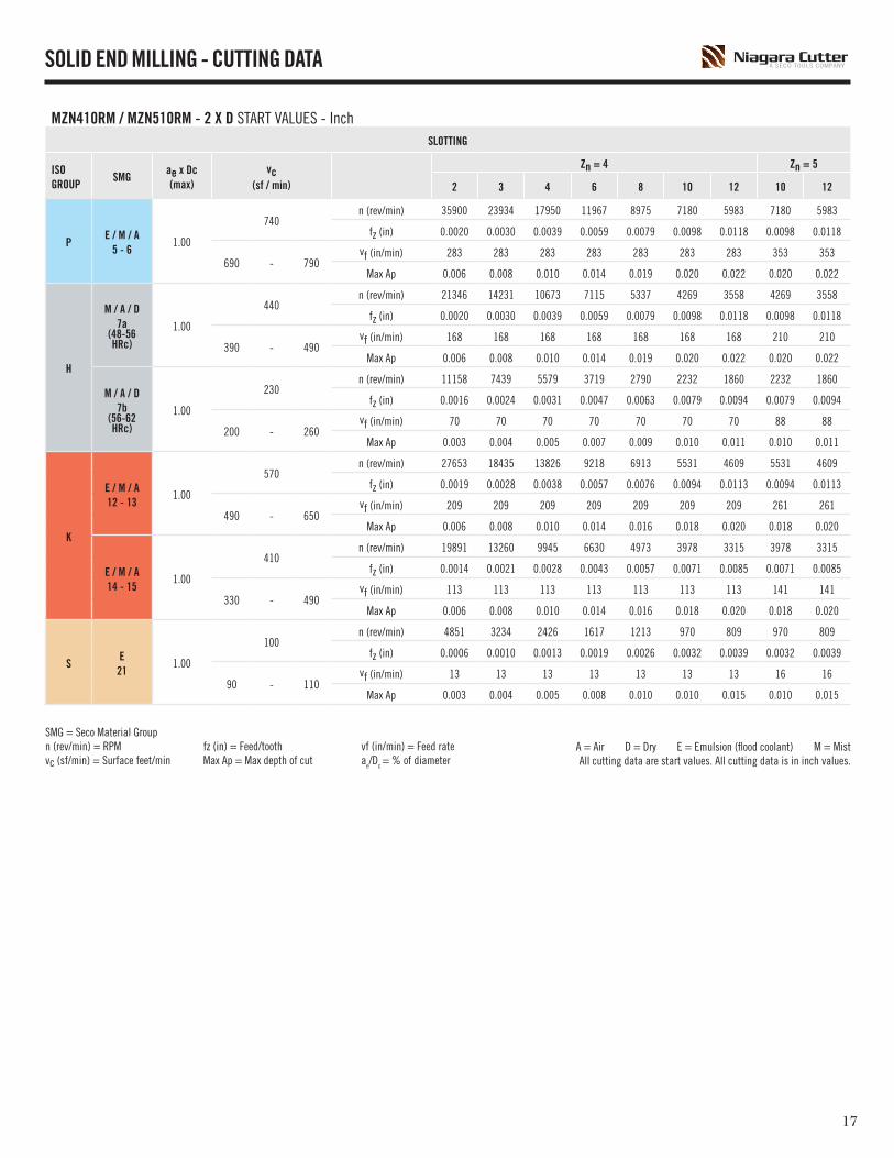
SOLID END MILLING - CUTTING DATA
MZN410RM / MZN510RM - 2 X D START VALUES - InchSLOTTING
ISOGROUP
SMGae x Dc
(max)vc
(sf / min)
Zn = 4 Zn = 5
2 3 4 6 8 10 12 10 12
PE / M / A
5 - 61.00
740n (rev/min) 35900 23934 17950 11967 8975 7180 5983 7180 5983
fz (in) 0.0020 0.0030 0.0039 0.0059 0.0079 0.0098 0.0118 0.0098 0.0118
690 - 790vf (in/min) 283 283 283 283 283 283 283 353 353
Max Ap 0.006 0.008 0.010 0.014 0.019 0.020 0.022 0.020 0.022
H
M / A / D7a
(48-56 HRc)
1.00
440n (rev/min) 21346 14231 10673 7115 5337 4269 3558 4269 3558
fz (in) 0.0020 0.0030 0.0039 0.0059 0.0079 0.0098 0.0118 0.0098 0.0118
390 - 490vf (in/min) 168 168 168 168 168 168 168 210 210
Max Ap 0.006 0.008 0.010 0.014 0.019 0.020 0.022 0.020 0.022
M / A / D7b
(56-62 HRc)
1.00
230n (rev/min) 11158 7439 5579 3719 2790 2232 1860 2232 1860
fz (in) 0.0016 0.0024 0.0031 0.0047 0.0063 0.0079 0.0094 0.0079 0.0094
200 - 260vf (in/min) 70 70 70 70 70 70 70 88 88
Max Ap 0.003 0.004 0.005 0.007 0.009 0.010 0.011 0.010 0.011
K
E / M / A12 - 13
1.00
570n (rev/min) 27653 18435 13826 9218 6913 5531 4609 5531 4609
fz (in) 0.0019 0.0028 0.0038 0.0057 0.0076 0.0094 0.0113 0.0094 0.0113
490 - 650vf (in/min) 209 209 209 209 209 209 209 261 261
Max Ap 0.006 0.008 0.010 0.014 0.016 0.018 0.020 0.018 0.020
E / M / A14 - 15
1.00
410n (rev/min) 19891 13260 9945 6630 4973 3978 3315 3978 3315
fz (in) 0.0014 0.0021 0.0028 0.0043 0.0057 0.0071 0.0085 0.0071 0.0085
330 - 490vf (in/min) 113 113 113 113 113 113 113 141 141
Max Ap 0.006 0.008 0.010 0.014 0.016 0.018 0.020 0.018 0.020
SE21
1.00
100n (rev/min) 4851 3234 2426 1617 1213 970 809 970 809
fz (in) 0.0006 0.0010 0.0013 0.0019 0.0026 0.0032 0.0039 0.0032 0.0039
90 - 110vf (in/min) 13 13 13 13 13 13 13 16 16
Max Ap 0.003 0.004 0.005 0.008 0.010 0.010 0.015 0.010 0.015
SMG = Seco Material Groupn (rev/min) = RPM fz (in) = Feed/tooth vf (in/min) = Feed ratevc (sf/min) = Surface feet/min Max Ap = Max depth of cut ae/Dc = % of diameter
A = Air D = Dry E = Emulsion (flood coolant) M = MistAll cutting data are start values. All cutting data is in inch values.

1918
SOLID END MILLING - CUTTING DATA
MZN410R / MZN510R - 2 X D START VALUES - InchSIDE MILLING
ISOGROUP
SMGae x Dc
(max)vc
(sf / min)
Zn = 4 Zn = 5
1/8 3/16 1/4 5/16 3/8 1/2 5/8 3/8 1/2 5/8
PE / M / A
5 - 60.50
825n (rev/min) 25212 16808 12606 10085 8404 6303 5042 8404 6303 5042
fz (in) 0.0050 0.0075 0.0100 0.0125 0.0150 0.0200 0.0250 0.0150 0.0200 0.0250
770 - 880vf (in/min) 504 504 504 504 504 504 504 630 630 630
Max Ap 0.005 0.006 0.008 0.001 0.013 0.014 0.016 0.017 0.017 0.017
H
M / A / D7a
(48-56 HRc)
0.50
480n (rev/min) 14669 9779 7334 5868 4890 3667 2934 4890 3667 2934
fz (in) 0.0050 0.0075 0.0100 0.0125 0.0150 0.0200 0.0250 0.0150 0.0200 0.0250
430 - 530vf (in/min) 293 293 293 293 293 293 293 367 367 367
Max Ap 0.005 0.006 0.008 0.001 0.013 0.014 0.016 0.017 0.017 0.017
M / A / D7b
(56-62 HRc)
0.50
260n (rev/min) 7946 5297 3973 3178 2649 1986 1589 2649 1986 1589
fz (in) 0.0038 0.0056 0.0075 0.0094 0.0113 0.0150 0.0188 0.0113 0.0150 0.0188
230 - 290vf (in/min) 119 119 119 119 119 119 119 149 149 149
Max Ap 0.004 0.006 0.007 0.009 0.011 0.015 0.019 0.015 0.015 0.019
K
E / M / A12 - 13
0.50
570n (rev/min) 17419 11613 8710 6968 5806 4355 3484 5806 4355 3484
fz (in) 0.0050 0.0075 0.0100 0.0125 0.0150 0.0200 0.0250 0.0150 0.0200 0.0250
490 - 650vf (in/min) 348 348 348 348 348 348 348 435 435 435
Max Ap 0.006 0.008 0.010 0.014 0.016 0.018 0.020 0.022 0.022 0.022
E / M / A14 - 15
0.50
410n (rev/min) 12530 8353 6265 5012 4177 3132 2506 4177 3132 2506
fz (in) 0.0038 0.0056 0.0075 0.0094 0.0113 0.0150 0.0188 0.0113 0.0150 0.0188
330 - 490vf (in/min) 188 188 188 188 188 188 188 235 235 235
Max Ap 0.006 0.008 0.010 0.014 0.016 0.018 0.020 0.022 0.022 0.022
SE
210.50
100n (rev/min) 3056 2037 1528 1222 1019 764 611 1019 764 611
fz (in) 0.0026 0.0039 0.0052 0.0065 0.0078 0.0104 0.0130 0.0078 0.0104 0.0130
90 - 110vf (in/min) 32 32 32 32 32 32 32 40 40 40
Max Ap 0.004 0.005 0.007 0.008 0.010 0.015 0.015 0.015 0.015 0.015
SMG = Seco Material Groupn (rev/min) = RPM fz (in) = Feed/tooth vf (in/min) = Feed ratevc (sf/min) = Surface feet/min Max Ap = Max depth of cut ae/Dc = % of diameter
A = Air D = Dry E = Emulsion (flood coolant) M = MistAll cutting data are start values. All cutting data is in inch values.

1918
SOLID END MILLING - CUTTING DATA
MZN410RM / MZN510RM - 2 X D START VALUES - InchSIDE MILLING
ISOGROUP
SMGae x Dc
(max)vc
(sf / min)
Zn = 4 Zn = 5
2 3 4 6 8 10 12 10 12
PE / M / A
5 - 60.50
825n (rev/min) 40024 26683 20012 13341 10006 8005 6671 8005 6671
fz (in) 0.0031 0.0047 0.0063 0.0094 0.0126 0.0157 0.0189 0.0157 0.0189
770 - 880vf (in/min) 504 504 504 504 504 504 504 630 630
Max Ap 0.006 0.008 0.010 0.014 0.019 0.020 0.022 0.020 0.022
H
M / A / D7a
(48-56 HRc)
0.50
480n (rev/min) 23287 15524 11643 7762 5822 4657 3881 4657 3881
fz (in) 0.0031 0.0047 0.0063 0.0094 0.0126 0.0157 0.0189 0.0157 0.0189
430 - 530vf (in/min) 293 293 293 293 293 293 293 367 367
Max Ap 0.006 0.008 0.010 0.014 0.019 0.020 0.022 0.020 0.022
M / A / D7b
(56-62 HRc)
0.50
260n (rev/min) 12614 8409 6307 4205 3153 2523 2102 2523 2102
fz (in) 0.0024 0.0035 0.0047 0.0071 0.0094 0.0118 0.0142 0.0118 0.0142
230 - 290vf (in/min) 119 119 119 119 119 119 119 149 149
Max Ap 0.003 0.004 0.005 0.007 0.009 0.010 0.011 0.010 0.011
K
E / M / A12 - 13
0.50
570n (rev/min) 27653 18435 13826 9218 6913 5531 4609 5531 4609
fz (in) 0.0031 0.0047 0.0063 0.0094 0.0126 0.0157 0.0189 0.0157 0.0189
490 - 650vf (in/min) 348 348 348 348 348 348 348 435 435
Max Ap 0.006 0.008 0.010 0.014 0.016 0.018 0.020 0.018 0.020
E / M / A14 - 15
0.50
410n (rev/min) 19891 13260 9945 6630 4973 3978 3315 3978 3315
fz (in) 0.0024 0.0035 0.0047 0.0071 0.0094 0.0118 0.0142 0.0118 0.0142
330 - 490vf (in/min) 188 188 188 188 188 188 188 235 235
Max Ap 0.006 0.008 0.010 0.014 0.016 0.018 0.020 0.018 0.020
SE
210.50
100n (rev/min) 4851 3234 2426 1617 1213 970 809 970 809
fz (in) 0.0016 0.0025 0.0033 0.0049 0.0066 0.0082 0.0098 0.0082 0.0098
90 - 110vf (in/min) 32 32 32 32 32 32 32 40 40
Max Ap 0.003 0.004 0.005 0.008 0.010 0.010 0.015 0.010 0.015
SMG = Seco Material Groupn (rev/min) = RPM fz (in) = Feed/tooth vf (in/min) = Feed ratevc (sf/min) = Surface feet/min Max Ap = Max depth of cut ae/Dc = % of diameter
A = Air D = Dry E = Emulsion (flood coolant) M = MistAll cutting data are start values. All cutting data is in inch values.

2120
SOLID END MILLING - CUTTING DATA
MZN410RM / MZN510RM - 4 X D START VALUES - InchSLOTTING
ISOGROUP
SMGae x Dc
(max)vc
(sf / min)
Zn = 4 Zn = 5
2 3 4 6 8 10 12 10 12
PE / M / A
5 - 61.00
740n (rev/min) 35900 23934 17950 11967 8975 7180 5983 7180 5983
fz (in) 0.0017 0.0025 0.0033 0.0050 0.0067 0.0084 0.0100 0.0084 0.0100
690 - 790vf (in/min) 240 240 240 240 240 240 240 300 300
Max Ap 0.005 0.006 0.008 0.011 0.015 0.016 0.018 0.016 0.018
H
M / A / D7a
(48-56 HRc)
1.00
440n (rev/min) 21346 14231 10673 7115 5337 4269 3558 4269 3558
fz (in) 0.0017 0.0025 0.0033 0.0050 0.0067 0.0084 0.0100 0.0084 0.0100
390 - 490vf (in/min) 143 143 143 143 143 143 143 179 179
Max Ap 0.005 0.006 0.008 0.011 0.015 0.016 0.018 0.016 0.018
M / A / D7b
(56-62 HRc)
1.00
230n (rev/min) 11158 7439 5579 3719 2790 2232 1860 2232 1860
fz (in) 0.0013 0.0020 0.0027 0.0040 0.0054 0.0067 0.0080 0.0067 0.0080
200 - 260vf (in/min) 60 60 60 60 60 60 60 75 75
Max Ap 0.002 0.003 0.004 0.006 0.007 0.008 0.009 0.008 0.009
K
E / M / A12 - 13
1.00
570n (rev/min) 27653 18435 13826 9218 6913 5531 4609 5531 4609
fz (in) 0.0016 0.0024 0.0032 0.0048 0.0064 0.0080 0.0096 0.0080 0.0096
490 - 650vf (in/min) 178 178 178 178 178 178 178 222 222
Max Ap 0.005 0.006 0.008 0.011 0.013 0.014 0.016 0.014 0.016
E / M / A14 - 15
1.00
410n (rev/min) 19891 13260 9945 6630 4973 3978 3315 3978 3315
fz (in) 0.0012 0.0018 0.0024 0.0036 0.0048 0.0060 0.0072 0.0060 0.0072
330 - 490vf (in/min) 96 96 96 96 96 96 96 120 120
Max Ap 0.005 0.006 0.008 0.011 0.013 0.014 0.016 0.014 0.016
SE21
1.00
100n (rev/min) 4851 3234 2426 1617 1213 970 809 970 809
fz (in) 0.0005 0.0008 0.0011 0.0016 0.0022 0.0027 0.0033 0.0027 0.0033
90 - 110vf (in/min) 11 11 11 11 11 11 11 13 13
Max Ap 0.002 0.003 0.004 0.006 0.008 0.008 0.012 0.008 0.012
SMG = Seco Material Groupn (rev/min) = RPM fz (in) = Feed/tooth vf (in/min) = Feed ratevc (sf/min) = Surface feet/min Max Ap = Max depth of cut ae/Dc = % of diameter
A = Air D = Dry E = Emulsion (flood coolant) M = MistAll cutting data are start values. All cutting data is in inch values.

2120
MZ645 / MZ645R - START VALUES - InchSIDE MILLING - ROUGHING
ISOGROUP
SMGap x Dc (max)
ae x Dc(max)
vc(sf / min)
Zn = 6
1/8 3/16 1/4 5/16 3/8 1/2
PE
5 - 61.50 0.10
450n (rev/min) 13752 9168 6876 5501 4584 3438
fz (in) 0.00075 0.00113 0.00150 0.00188 0.00225 0.00300
390 - 510 vf (in/min) 62 62 62 62 62 62
H
M / A / D7a
(48-56HRc)1.00 0.05
450n (rev/min) 13752 9168 6876 5501 4584 3438
fz (in) 0.00056 0.00084 0.00113 0.00141 0.00169 0.00225
435 - 465 vf (in/min) 46 46 46 46 46 46
M / A / D7b
(56-62HRc)1.00 0.02
400n (rev/min) 12224 8149 6112 4890 4075 3056
fz (in) 0.00040 0.00060 0.00080 0.00100 0.00120 0.00160
385 - 415 vf (in/min) 29 29 29 29 29 29
MZN410RM / MZN510RM - 4 X D START VALUES - InchSIDE MILLING
ISOGROUP
SMGae x Dc
(max)vc
(sf / min)
Zn = 4 Zn = 5
2 3 4 6 8 10 12 10 12
PE / M / A
5 - 60.50
825n (rev/min) 40024 26683 20012 13341 10006 8005 6671 8005 6671
fz (in) 0.0027 0.0040 0.0054 0.0080 0.0107 0.0134 0.0161 0.0134 0.0161
770 - 880vf (in/min) 429 429 429 429 429 429 429 536 536
Max Ap 0.005 0.006 0.008 0.011 0.015 0.016 0.018 0.016 0.018
H
M / A / D7a
(48-56 HRc)
0.50
480n (rev/min) 23287 15524 11643 7762 5822 4657 3881 4657 3881
fz (in) 0.0027 0.0040 0.0054 0.0080 0.0107 0.0134 0.0161 0.0134 0.0161
430 - 530vf (in/min) 249 249 249 249 249 249 249 312 312
Max Ap 0.005 0.006 0.008 0.011 0.015 0.016 0.018 0.016 0.018
M / A / D7b
(56-62 HRc)
0.50
260n (rev/min) 12614 8409 6307 4205 3153 2523 2102 2523 2102
fz (in) 0.0020 0.0030 0.0040 0.0060 0.0080 0.0100 0.0120 0.0100 0.0120
230 - 290vf (in/min) 101 101 101 101 101 101 101 127 127
Max Ap 0.002 0.003 0.004 0.006 0.007 0.008 0.009 0.008 0.009
K
E / M / A12 - 13
0.50
570n (rev/min) 27653 18435 13826 9218 6913 5531 4609 5531 4609
fz (in) 0.0027 0.0040 0.0054 0.0080 0.0107 0.0134 0.0161 0.0134 0.0161
490 - 650vf (in/min) 296 296 296 296 296 296 296 370 370
Max Ap 0.005 0.006 0.008 0.011 0.013 0.014 0.016 0.014 0.016
E / M / A14 - 15
0.50
410n (rev/min) 19891 13260 9945 6630 4973 3978 3315 3978 3315
fz (in) 0.0020 0.0030 0.0040 0.0060 0.0080 0.0100 0.0120 0.0100 0.0120
330 - 490vf (in/min) 160 160 160 160 160 160 160 200 200
Max Ap 0.005 0.006 0.008 0.011 0.013 0.014 0.016 0.014 0.016
SE21
0.50
100n (rev/min) 4851 3234 2426 1617 1213 970 809 970 809
fz (in) 0.001 0.002 0.003 0.004 0.006 0.007 0.008 0.007 0.008
90 - 110vf (in/min) 27 27 27 27 27 27 27 34 34
Max Ap 0.002 0.003 0.004 0.006 0.008 0.008 0.012 0.008 0.012
SOLID END MILLING - CUTTING DATA
SMG = Seco Material Groupn (rev/min) = RPM fz (in) = Feed/tooth vf (in/min) = Feed rate vc (sf/min) = Surface feet/min Max Ap = Max depth of cut ae/Dc = % of diameter ap/Dc = % of diameter
A = Air D = Dry E = Emulsion (flood coolant) M = MistAll cutting data are start values. All cutting data is in inch values.

2322
PROFILE HEIGHT
ap
ae
Dc
f
fz
zn
n
Q
vc
vf
Dw
=
=
=
=
=
=
=
=
=
=
=
Depth of cut (mm) / axial depth of cut (in)
Width of cut (mm) / radial depth of cut (in)
Cutter diameter
Feed per revolution (in/rev)
Feed per tooth (in/tooth)
No. of teeth
RPM (rev/min)
Material removal rate (in3/min)
Cutting speed (sf/min)
Feed speed (in/min)
Working diameter
Surface speed, surface footage and surface area are directly related. Cutting speed is the peripheral speed (velocity) at the outside edge of an endmill (surface speed). The faster the spindle speed the higher the SFM. SFM is the distance in feet that the cutting edge travels in one minute. IPM and IPT is the rate at which the cutting tool is advanced into the workpiece.Feed per tooth is the thickness of chip that each cutting edge removes in one pass.
Profile height H (um)
Dc
Pitch ae (mm)
0.06 0.08 0.11 0.15 0.20 0.30 0.45
1 0.90 1.60 3.00 5.70 10.00 23.00 53.00
2 0.45 0.80 1.50 2.80 5.00 11.00 26.00
4 0.23 0.40 0.76 1.40 2.50 5.60 13.00
6 0.15 0.27 0.50 0.94 1.70 3.80 8.40
8 0.11 0.20 0.38 0.70 1.30 2.80 6.30
10 0.09 0.16 0.30 0.56 1.00 2.30 5.10
12 0.08 0.13 0.25 0.47 0.83 1.90 4.20
RPM
(rev/min)
CUTTING SPEED
(sf/min)
FEED SPEED
(inch/min)
FEED PER REVOLUTION
(inch/rev)
METAL REMOVAL RATE
(inch3/min)
CUTTING SPEED AND RPM FOR COPYING
(sf/min)
(RPM)
(inch)
CALCULATION OF ap VS. OVERHANG LENGTH:If the overhang length (XS) is longer than 4 x Dc and cylindrical shanks are used, it is important to adopt another depth of cut (ap) value than that indicated in the table.Use the following formula to calculate the new ap value
MILLING CALCULATIONS

2322
The table below shows the minimum hole diameter that should be made per the diameter of the end mill being used.
RECOMMENDED DIAMETER OF HOLE FOR HELICAL INTERPOLATION RAMPING
DIAMETER OF END MILL DC DIAMETER OF HOLE
1/32 - 3/32 1.4 x Dc
1/8 - 1/4 1.3 x Dc
3/8 - 1/2 1.2 x Dc
5/8 - 1 1/4 1.15 x Dc
TROCHOIDAL METHODThe figure below shows a method often called the trochoidal method for milling slots.
RECOMMENDED WIDTH OF SLOT
DIAMETER OF END MILL DC SLOT WIDTH1/32 - 3/32 1.8 x Dc
1/8 - 1/4 1.6 x Dc
3/8 - 1/2 1.4 x Dc
5/8 - 1 1/4 1.2 x Dc
HELICAL INTERPOLATION
CORNER CONTACT
Generate component corners to optimize tool life.
• Use maximum diameter of cutting tool, but have maximum difference between the radius of the tool and the radius in the corner of the component.
• In a corner, the contact arc of the tool increases rapidly according to the difference in radius between the tool and the component. This causes more force on the tool, resulting in deflection and increased temperature in the corner, reducing tool life.
RECOMMENDATIONS
END MILL DIAMETER MINIMUM CORNER RADIUS
1/64 - 3/32 Dc / 2 x 1.4
1/8 - 1/4 Dc / 2 x 1.3
3/8 - 1/2 Dc / 2 x 1.2
5/8 - 1 1/4 Dc / 2 x 1.15
Ex: ¼ tool, minimum corner radius to be generated is 0.1625”.
CornerRadius
MILLING CALCULATIONS

PB24
NIAGARA CUTTER, LLCNorth American Production Unit150 South Fifth StreetReynoldsville, PA 15851-0279
NIAGARACUTTER.COM
Niagara Cutter is a Seco Tools Company.
SECO TOOLS, LLC North American Headquarters2805 Bellingham Drive Troy, MI 48083248-528-5200
SECOTOOLS.COM
P-1807-3000 GT18-507Copyright © 2018 Seco Tools, LLC Printed in USA. All rights reserved.
To find an Authorized SECO/Niagara Cutter Distributor near you, please refer to our Distributor Locator:
SECOLOCATOR.COM
For technical assistance, call: 1-800-832-8326
For customer service, call: 1-248-528-5220