reduced-complexity spatial and temporal processing of...
TRANSCRIPT
Reduced-complexity spatial and temporal processing of .underwater acoustic communication signals
M. Stojanovic, J. A. Catipovic, a) and J. G. Proakis Department of Electrical and Computer Engineeri.g, Northeastern Universit); Boston, Massachusetts 02 !15
(Received 23 December 1993; accepted for publication 6 March 1995)
Multichannel processing of high-speed underwater acoustic communication signals requires computationally intensive receiver algorithms. The size of adaptive filters, determinsd by the extent of ocean multipath, increases with signaling rate and limits system performance through large noise enhancement and increased sensitivity of computationally efficient algorithms to numerical errors. To overcome these limitations, reduction in receiver complexity is achieved b• exploiting the relationship between optimal diversity combining and beamforming. Under relatively simple conditions, two adaptive receivers, one ba.'ied on diversity combining which does not rely on any spatial signal distribution, and the other based on optimal beamforming, are .';hown to achieve the same performance. The beamforming approach, however, leads to a receiver of lower complexity. Carrying these observations over to a general case of broadband transmission through an unknown channel, a fully adaptive receiver is dew:loped which incorporates a mnlti-inpttt multi-output, many-to-few combinet, and a reduced-complexity multichannel equalizer. Receive- operations are optimized jointly to ensure minimum mean-squared error performance of data detection. Results of processing experimental shallow water data demonstrate the capability to fully exploit spatial diversity of underwater multipath while keeping the complexity at an acceptable level. ̧ 1995 Acoustical Society of America.
PACS numbers: 43.60.Gk, 43.30.Wi
INTRODUCTION
A major problem for achieving reliable, high-speed un- derwater acoustic (UWA) communications is the large amount of intersymbol interference (ISI) encountered in many of the ocean channels. Examples of dynamic multipath ocean channels include mainly the horizontal channels, such as long-range deep water channels, in which many propaga- tion paths meet at multiple convergence zones, and various shallow water channels in which multipath is comprised of both deterministic and random, bottom, volume an-- surface
reverberation. Depending on the signaling rate used, ocean multipath can impose severe limitations on coherenl recep- tion, due to both its large time and frequency spreads.
Two basic strategies for dealing with multipath in UWA communications are (l) to design signals which ensures the absence of ISI, and (2) to design receivers capable of com- pensating for the ISI. The first group includes the simplest strategy, in which the transmitted pulses of the same fre- quency are separated in time far enough to ensure that all channel reverberation will die out before each subsequent pulse is to be received, • and the more complex systems which use spread-spectrum signals to reject multipath. •- Both of these techniques sacrifice data throughput to eliminate the ISI. The more sophisticated systems of the second group allow for the ISI in the received data sequence, thus •upport- ing high-speed communications through efficient use of the available bandwidth. Several types of channels, name ly long- range deep and shallow water, and medium-range shallow
a)Present address: Woods Hole Oceanographic Institution, Woods Hole, MA 02543.
water channels, have been shown to allow effective use of
adaptive equalization methods for combating the ISI? A different approach to eliminating multipath propaga-
tion is the use of nan'ow beams, either at the transmitter or
receiver end, which ensure that only a single deterministic propagation path con•;ributes to the received signal. At the transmitter end, parametric sources which rely on the nonlin- earity of transmission medium in front of a transducer, are used to excite only a single mode of propagation. 4's How- ever, such sources are still considered impractical since in addition to pointing e•rors, their major limitation lies in high power requirements. a As an alternative to equalization, beamforming at the receiver end has been used to isolate the signal from a single propagation path based on its angular separation from undesired multipath. s3
In addition to tempora' variability, spatial variability of the ocean mnltipath represents a major problem for the single-channel receiver performance and motivates the use of multiple, spatially dis'ributed sensors. Practical justification for investigating multichannel signal processing techniques lies in the relative simplicity of building large receiver arrays for applications such as LWA telemetry. Spatial diversity offers robustness to fading. provided that the beamforming and equalization techniques are properly combined, so as to exploit, rather than suppres.• the multipath propagation.
The use of spatial diw'•rsity combining for UWA com- munic•,tions was originally investigated for the case of non- dispersive channels. s For frequency selective UWA channels, the design of the receivers which jointly perform spatial di- versity combining and equalization, and their experimental performance results, were Fresented in Ref. 9. Recent refer- ences to multichannel equalization with applications to UWA
961 J. Acoust. Soc. Am. 98 (2), Pt. 1, August 1995 0001-4966/95/98(2)/961/12/$6.00 ¸ 1995 Acoustical Society of America 961
Downloaded 07 Sep 2010 to 141.154.209.135. Redistribution subject to ASA license or copyright; see http://asadl.org/journals/doc/ASALIB-home/info/terms.jsp

communications also include Ref. 10 which demonstrates the
advantages of spatial diversity combining using a time- invariant simulation model for medium-range shallow water channels.
Although techniques for joint beamforming and equal- ization have been proposed for other communication channels, n their potential has not yet been fully recognized in application to UWA communications. The use of a beam- former and a single-channel equalizer as complementary de- vices was suggested in Reft 12. It was found that while beamforming is effective for small range-to-depth ratios, an increase in range precludes angular multipath separation, ne- cessitating the use of an equalizer. Similar conclusions are made in a recent overview of UWA communication systems 5 suggesting that the receiving strategy be moved from beam- forming to equalization to diversity combining as the range increases relative to depth.
Multichannel, or spatial diversity equalization, analyzed in Reft 9 represents a more general approach to spatial and temporal signal processing, effecfve for all range-to-depth ratios. This multichannel equalizer demonstrated superior performance over the single-channel case in configurations with only few channels. However, although it achieves near- optimal performance, its computational complexity signifi- cantly increases with the number of array sensors. This be- comes a major limitation at high signaling rates when each of say, 20 input channels needs a 100-tap equalizer. Besides the increase in computational time, very large adaptive fil- ters, which must operate with computationally efficient algo- rithms, imply increased sensitivity to numerical errors. Un- fortunately, some of the fast RLS algorithms •3 preserve numerical stability only at the expense of sacrificing the tracking speed. As an alternative, a class of LMS algorithms with improved tracking properties has been proposed 14 for application in UWA equalization; however, its performance in the dynamic, nonstationary UWA environment still lacks the fast convergence properties of the RLS algorithms. An- other disadvantage of large multichannel equalizers, and per- haps the critical one, lies in their increased noise enhance- ment, which significantly limits the gain obtained by increasing the number of channels.
These issues motivate the search for a different multi-
channel processing strategy in which the size of the adaptive filter will be reduced, but multipath diversity gain preserved. To this end, we start out in Sec. I by investigating the rela- tionship between optimal diversity combining and beam- forming. While beamforming is associated with large arrays, whose geometry permits them to reject interference by steer- ing nulls in some directions, diversity combining can be per- formed with as few as two sensors, which only need to be separated far enough from each other to ensure independence of the received signals. Diversity combining alone does not account for channel equalization, and thus has to be used in conjunction with it. On the other hand, due to the large amount of multipath present in the UWA channels, an array could be used to repeatedly steer nulls in the directions of all but one signal reflection, and subsequently combine the ISI-
free signals. In other words, a conventional beamformer, as termed in the array processing literature, would be used to cancel the unwanted signal interference, TM while a diversity combinet, as found in communications literature, would try to make use of repetitive signal arrivals. 16,1? While there is a fundamental difference between the two techniques, both are used to mitigate ISI and fading caused by multipath propa- gation. We explore this fact to arrive at the optimal beamforming/combining strategy.
The analysis of optimal combining gives rise to two classes of adaptive implementations depending on whether knowledge of the spatial signal distribution is used by the receiver. The first class does not rely on such knowledge and corresponds to pure diversity combining. 9 The receivers of the second class exploit the fact that there exists a certain relationship between the array signals, and correspond to op- timal beamforming. To compare the two approaches consid- ered, a condition is derived in Sec. II for equivalence be- tween a fully adaptive multichannel equalizer of the first class, and a less complex receiver which has perfect knowl- edge of the angles of multiple signal arrivals and uses it in a fixed beamformer. Performance of several beamforming strategies is studied on a simulation example, revealing that the interpretation of an optimal receiver as a beamformer and subsequent combinet leads to a receiver structure which sig- nificantly reduces the complexity of a pure diversity com- biner, while achieving the same performance.
These ideas, derived from a narrow-band case, are ex- tended in Sec. III to a broadband underwater acoustic com-
munication scenario. In this case, the reduced-complexity re- ceiver configuration is structurally suboptimal; nevertheless, it allows simultaneous optimization of the "beamformer" and the multichannel equalizer. Such an approach provides the desired reduction in complexity, and hence, improved algorithm stability and reduction in noise enhancement. An essential part of a practical receiver is a multichannel carrier phase estimator which provides necessary reference for co- herent combining of multichannel signals. The key feature of the proposed algorithm is joint optimization of the combinet, or spatial processor, the multichannel decision-feedback equalizer (DFE) and the accompanying digital phase-locked loops (PLL), based on minimization of the mean-squared error (MSE) in the data detection process. The algorithm derivation is presented and the issues concerning its imple- mentation are discussed.
Experimental results demonstrate excellent receiver per- formance on a long-range (50 nautical miles) shallow-water (about 50-m deep) channel off the New England Continental Shelf. We study cases of digital data transmitted at rates up to 2000 bits per second using 4- and 8-level phase shift key- ing (?SK), and received over a 20-element vertical array. The results lead us to conclude that the proposed class of reduced-complexity, but fully adaptive receivers for simulta- neous beamforming and multichannel equalization is espe- cially well-suited for real-time implementation ia UWA mo- dems.
962 J. Acoust. Soc. Am., Vol. 98, No. 2, Pt. 1, August 1995 Stojanovic et aL: Spatial and temporal processing 962
Downloaded 07 Sep 2010 to 141.154.209.135. Redistribution subject to ASA license or copyright; see http://asadl.org/journals/doc/ASALIB-home/info/terms.jsp
= ,40 * ß RX
TX
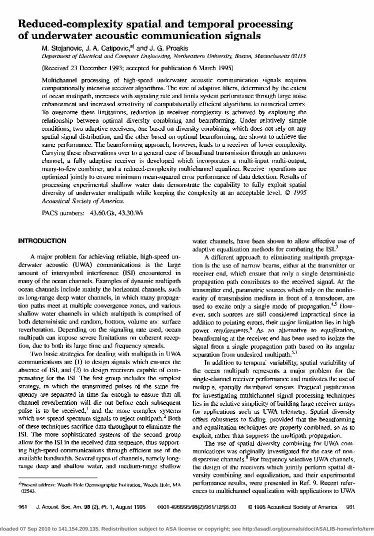
FIG. I. Propagation model (P=2, K=4).
I. ADAPTIVE MULTICHANNEL PROCESSING: THE BEAMFORMING AND THE DIVERSITY COMBINING APPROACH
A. Propagation mode
An acoustic channel can be modeled as consisting of a number of deterministic propagation paths, each described by an impulse response which takes into account any pos- sible dispersion on the given deterministic path. V•e accord- ingly consider a channel in which the transmitted signal u(t) propagates over a number of paths, P, each of which is char-
acterized by its complex baseband impulse response cp(t). The multipath signal is received over K equally spaced sen- sors, as sketched in Fig. I. To illustrate the model, we con- sider the simple narrow-band case, with ideal plane-wave propagation. In this case, the signal propagating via the pth path, up(t) = u(t)*cp(t), is observed at the kth :lensor as up(t)e-Jk•%, where top .is the angle associated with the pth propagation path. The vector of the received signals is given as
v(t) = : = vx_,(t)J : ':
Le-jiK-I);P• ... e-jiK-I•vP
[ u,(t)J Ln•c- i(t)
= •u(t) + n(/). (l)
The noise components n,(t) are assumed to be independent of the signal. The signal u(t) depends on the underlying transmitted sequence of data symbols {d(n)} as
u(t)-- a(n)g(t-nT), (2)
where g(t) is the vector of overall path responses g•(t) = %(t)*g(t), which include all the transmitter and receiver filtering g(t). Wit.h this notation, the received signal (i) is written as
v(t) = •] d(n)f(t- n T) + n(t), (3) rt
where
f(t): a,g(t) (4)
is the vector of overall channel responses.
B. The role of beamforming in the optimal combiner
Assuming that the noise vector n(/) is zero-mean, tem- porally white, Gaussian, with a known covariance Rn, the optimal, maximum likelihood (ML) receiver consists of a combinet and a postprocessor for detecting the transmitted data sequence. 9 The optimal combinet incorporates a bank of K matched filters with i•npulse responses f•(-t), whose outputs are summed and sampled at the signaling rate. The combinet output, produced at discrete intervals of time n T, is given by (prime denotes conjugate transpose)
y(n)= Lrtt--nr)R,7v(t)dt (5) and it constitutes the' decision variable for determining the transmitted sequence {d(n)}. Regardless of the detection process, which can be re•,lized as maximum-likelihood se- quence estimation or stone form of sequential detection based on equalization, the .:ombining process is described by Eq. (5). Since we are primarily concerned with the combin- ing problem, we shall stay with linear equalization methods, as the simplest to analyze, for the rest of our present discus- sion. A practical receiver, based on decision-feedback equal- ization which is especially suitable for UWA signal process- ing, will be described in Sec. IlL
So far, we have made no assumptions about the spatial distribution of signals across the array. Should there exist a relationship between signals observed at different sensors, the optimal combinet has a special interpretation. For the narrow-band case and plane-wave propagation, for which the spatial signal distribution is given by (4), the output of the optimal combinet can be represented as
y(n)= fr•g'(t--nr)aa'Rj •v(t)dt. (6) This expression implies a different combiner structure in which the parts corresponding to "beamforming," and those corresponding to matched filtering and coherent combining are clearly separated. The beamforming part is identified as depending only on the angles of signal arrivals, and is rep- resented by a KX P beamforming matrix •b. The P signals at its oulput are associated aith the P propagation paths, and the P fillers are matched to the individual path responses gv(t). The gain obtaiued in the optimal combinet in the case of uncorrelated multipath is proportional both to the number of sensors and to the nulnber of propagation paths.
C. Two classes of adapt;ve combiners
Although theoretically identical, the two combiner struc- tures discussed give rise to different adaptive implementa- tions depending on whether knowledge of the spatial signal distribution is available at the receiver. If the receiver has no
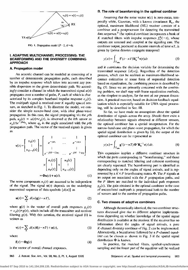
information about the angles of signal arrivals, a pure K-channel diversity combiner of Fig. 2 can be implemented. Alternatively, a beamlbrmer followed by a P-channel equal- izer can be chosen as shown in Fig. 3 if the spatial signal distribution 4) is known.
In practice, the matched filters, symbol-synchronous sampling and the linear part of the equalizer will be realized
963 d. Acoust. Soc. Am., Vol. 98, No. 2, Pt. 1, August 1995 Stojanovic et aL: Spatial and temporal processing 963
Downloaded 07 Sep 2010 to 141.154.209.135. Redistribution subject to ASA license or copyright; see http://asadl.org/journals/doc/ASALIB-home/info/terms.jsp

FIG. 2. Adaplive receiver with K-channel equalizer.
together in a bank of fractionally spaced adaptive filters of finite length. Accordingly, we consider optimizing the finite length receivers based on minimization of the MSE between the true and the estimated data symbol,
MSE= E{la(,•)-•(n)12}. (7) Referring to Figs. 2 and 3, the estimated data symbols of the two receivers are given by
•l(rt) = C'V[rt ] (8)
•z(") = a' w[n]. (9) The equivalent input signal vector v[n] for the full K-channel equalizer consists of the vectors v•.[n] of the T.•-spaced received signal samples currently stored in the kth equalizer, and the equivalent input signal vector win] for the P-channel equalizer is composed of the vectors
w•[.] = [vo[.]...v,•_,[,,]]• = v[.]t,•.
where bt, is the pth column of B. Guided by the structure of the optimal receiver, in the case of spatially white input noise, the beamforming transformation will be chosen as B--(b.
The MMSE solutions for the overall equalizer tap- weight vectors are given by
c= R•J Roa, (ll)
- - • (•2) a-- R•, wR•d,
where the notation R,,y=E{x[n]y'[n]} is used to denote the cross correlations. Hence, any form of adaptive, decision- directed algorithm can be applied to the signals v[n] and w[n] to obtain the mbitichannei equalizer tap-weights c and a, respectively.
•/T,
' • I __ •/r I I
I ' I I FIG. 3. Adaptive receiver with beamformer and P-channel equalizer.
064 d. AcousI. $oc. Am., Vol. 08, No. 9, Pt. 1, August 109õ
1. Joint adaptive equalization and angle of arrival tracking
So far we have assumed that the receiver has knowledge of the angles of arrival, or their estimates, which it uses in a fixed beamformer. However. because of the relative motion
between the receiver and the transmitter, the true angles of arrival will change with time. A tracking algorithm for the estimates {½t,} can be obtained by^ exploiting the special structure of the transformation B=tb which corresponds to the optimal combiner's beamforming part.
To find the MMSE estimates of the angles {½t,} which are joinfly optimal with the equalizer vectors {at, }, it is con- venient to use the shorthand notation
K-I
Pt,.,:a't,v•[nl, Pt,(•)= • Pt,.•d**. (13) k=O
The error e(n)=d(n)-•(n) can now be expressed in terms of ½t, as
•(,•) =d(n)- • P•(½,)- Pt,(½t,) = Q•-
(14)
where Qt, is independent of ½t,. Differentiating the MSE with respect to ½t,, we obtain
•MSE
--2 Re{E{13p(½p)e*(n)}}, K-I
r• P t,( • ) - Pv(qo)-- •qo --J • kPt,'•eJt•' =JFv(qø)' (15)
With this notation, the MMSE solution ½t, has to satisfy o•MSE
-2 lm{E{Ft,(½t,)[Qt,-Pt,(½p)]*}}=O. (16)
An important difference between the two classes of adaptive receivers now becomes evident. Because of the con- strained structure of the matrix 4). the expression (16) has no closed form solution. At the same time, the tap-weights c of the fully adaptive K-channel equalizer have the closed-form MMSE solution (11).
To obtain a recursive solution for the angles {½t,}. we define the angular error at iteration n as
½p(n):Im{Ft,(½t,(n))e*(n)}, p= 1 ..... P. (17)
The current estimate ½t,(n) can then be updated as
½t,(,,+ t )=,3t,(•)-x,%(,,)-x2 • %(-0, m--0
p=l ..... P (18)
with appropriately chosen angle-tracking constants K• ,K 2, and initial values of the estimates. The outlined solution is
analogous to a second-order digital PLL. Note, however, that (18) represents only the angle-locked loop, and that for prac- tical applications, an additional carrier phase tracking loop might have to be associated with each of the propagation paths to compensate for their carder frequency distortions.
Stojanovic et aL: Spatial and temporal processing 964
Downloaded 07 Sep 2010 to 141.154.209.135. Redistribution subject to ASA license or copyright; see http://asadl.org/journals/doc/ASALIB-home/info/terms.jsp
II. COMPARISON OF COMBINERS
If the number of sensors is larger than the number of propagation paths, the class of receivers which rely on the spatial signal distribution has a lower computational com- plexity. For applications such as high-rate telemetry over se- verely dispersive channels, any reduction in comp'exity be- comes extremely important. On the other hand, a fully adaptive K-channel equalizer has the main advantage in not requiting any a priori knowledge of the spatial distribution of signals, such as the number of multiple arrivals. It is there- fore insensitive to any model mismatch, in the sel•se that it implicitly estimates the model parameters during the process of adaptation. Hence, a question arises as to whether there are beamforming strategies which could perform equally well but are not constrained on the explicit knowledge of propagation conditions.
A. Condition for equivalence between the two classes of combiners
Now we wish to compare the performance cf a fully adaptive K-channel equalizer to that of a reduced-complexity structure which employs an arbitrary KXP beamforming matrix B and an adaptive P-channel equalizer. We assume a stationary environment, described by fixed angles of signal arrivals.
The input signal vector win] for the reduced-complexity receiver of Fig. 3 is expressed in terms of the input signal vln] as
w[n ] = B,vv[ n ]. I b[ll N ... b•l•] : . 09) b•vl • ... b•vI•]
The elements {bt,•} constitute the beamforming inatrix B. and Iv is the identity matrix of size N equal to the number of equalizer tap weights in each branch. The matrix B•v is thus obtained by "expanding" the matrix Bi=B. Using the ex- pression (19), the cross correlations which determine the op- timal receivers (11) and (12) are related by
Rwd = B•vR.d, R•...= B•R•,oB•v. (20)
From (3), the input signal vector can be expressed as
v[n] = •N• d(m)g[n-- m] + n[n ]. (21)
where (I),v is the Nth expansion of q), and giro] con.,ists of P vectors of T•-sampled path responses, shifted by m symbol intervals with respect to the center vector g[0]=g. Using this representation, the signal covariance is obtained as
R•,o = {I)•v[ gg' + G] {I)• + R,,, = q)tqgg' q• + N, (22)
where
G= • g[m]g'[m] (23) m•'O
defines the noise term associated with ISl.
The steady-state MSE achieved by the K-channel equal- izer is now given by
' • - /[i +g'd•N-'•l•g]. MMSE•= 1 -RodRo• at, d- 1 (24)
Similarly, using the expressions (20), the MMSE achieved by the smaller P-channel equalizer is
MMSEp = I - R,',.dR•,•.R•.a
=1/[I , , , -I ' q- g ½batBtv(B:vNB•v) Btvtb•vg]. (25)
We shall say that the two structures are equivalent if they achieve the same MMSEs. In order for the equivalence to hold for arbitrary path responses g, the following relation must hold
4,•B•v(B•,NB.v) • ' B.[,!)•v= 4)•N- 'q•v ß (26)
Since all the required inve:ses are those of covariance matri- ces. we can assume their existence. and substitute for the
overall noise covaliance N as defined by Eq.' (22), to Obtain the equivalent relationship
q,•vBtv(BL.R,,.Btv) 'B•vd)•v = (b•R..'½b•,. (27)
To fnrther simplit3' the obtained expression, we use the fact that the Nth expansions of any matrices X and Y satisfy X•vY•-=(XY)•v and, hence, for a square matrix, X•v• =:( X •)•v- In the case of white input noise, the condition (27) finally reduces to
q½ B(B'B) •B'q)= •.'d). (28)
Whenever the chosen beamformer B satisfies this simple condition, the performance of the reduced-complexity re- ceiver will equal that of the full K-channel equalizer. This is an interesting conclusion since it says that any kind of beam- forming, which'satislies the condition (28), can be used to reduce the computational complexity of the full multichannel equalizer. In other words, it is not necessary to use B=• of the optimal combinet, since as long as (28) is satisfied, the P-channel equalizer will be able to achieve the overall MMSE solution. By inspection, we see that the optimal com- binerN beamformer B =(I) •atisfies the equivalence condition (28). 'Thi• is also true lb' the conventional beamformer •5 B--•,tI)'•) •, which produces at its output an estimate of the spatially separated signals u(t). In fact, whenever B can be expressed as a product of the angle matrix (I) and an arbitrary invertible matrix, it will satisfy the equivalence condition. The necessary condition for the equivalence (2.8) to hold is that the s•ze o; the matrix B, i.e., the reduced
number of channels to be equalized, not be smaller than the number of propagation pat•s.
B. Reduced-complexity unconstrained combining
While the two approaches considered in Sec. I represent two extremes, the above analysis encourages us to combine them, in order to reduce the computational complexity of the fully adaptive multichannel equalizer, but make no explicit assum0tions about the underlying spatial signal distribution. This can be accomplished by using a KX P adaptive beam- foriner of unconstrained structure, together with a P-channel equalizer. In fact, P here does not have to have the same physical meaning as i • the optimal combinet structure. Joint
965 d. Acoust. Soc. Am., Vol. 98, No. 2, Pt. 1, August 1995 Stojanovic et aL: Spatial and temporal processing 965
Downloaded 07 Sep 2010 to 141.154.209.135. Redistribution subject to ASA license or copyright; see http://asadl.org/journals/doc/ASALIB-home/info/terms.jsp

SNRia
FIG. 4. Performance comparison of (a) fixed beamformers and (b) fully adaptive receivers.
optimization of the beamformer and the equalizer elements will ensure the MMSE performance of the given receiver structure. A special case with P = 1 was analyzed in Ref. 11 which gives an interesting analysis of the shared tasks of beamforming and equalization.
The optimal MMSE value of the overall beamforming vector b' = [b[.--b•,] is given by
b= R.d, (29)
where u[n] is comprised of the equivalent input signals to the beamformer,
%[.]=V•[.]a• *, •,=l ..... •'. (30) The beamformer coefficients (29) and the equalizer coeffi- cients a from (12) will be used together to obtain the algo- rithm for joint adaptation of the beamformer and the equal- izer, as described in more detail in the following section.
With each of the equalizers having length N, a total of K X P + P x N taps have to be computed per iteration, as op- posed to the KXN taps of the full diversity combinet.
Although this receiver structure resembles a subarray beamformer, Is both the matrix beamformer and the reduced- complexity multichannel equalizer remain adaptive. As long as there exists an underlying spatial signal distribution which permits the decomposition of the optimal combiner into the beamformer and the reduced-complexity equalizer, no per- formance degradation need result from the reduction in com- plexity.
C. Simulation example
The purpose of this simulation is to illustrate the impact of the choice of a combining strategy on the receiver perfor- mance and its complexity. Consider a simple example with P=2 propagation paths, K=4 array sensors, and spatially white noise. Assuming that the angles •o• and • are known, we compare several possible beamforming strategies. A ma- trix beamformer is chosen either in an optimal fashion, B=•, or as a conventional beamformer, B=q•(•'•) -]. An alternative approach to resolving the two signal arrivals is to group the elements of the array into two groups, dedicating
each group to beamforming toward one of the arrivals. Note that this approach is somewhat similar to space-beam pro- cessing, another strategy used in array processing to reduce the computational complexity of fully adaptive arrays? A minimum of K=4 elements is needed for such split beam- forming. Each of the two beamformers can use any of the classical criteria for interference suppression. Minimum vari- ance (MV), MMSE, or ML criteria differ only by a scalar factor, is and are equivalent from a data-detection point of view. Regardless of the optimization method for the two- element beamforming vectors bli and b22 , the overall beam- forming matrix
will not satisfy the condition (28). Hence, split beamforming cannot achieve the performance of nonrestricted, full-matrix beamforming.
The performance of these three fixed beamformers op- erating with a 2-channel adaptive equalizer is illustrated through the simulation results shown in Fig. 4(a). The fol- lowing parameters were used:
modulation: QPSK transmitter and receiver pulse: raised cosine (roll-off 0.5,
total duration 4 T) dift•rential path delay: 2.5 T path power ratio: 1 array element spacing: d=M2 angles of arrival: a] =30ø; a2=-20 ø equalizer: 13 taps, T/2-spaced adaptive algorithm: RLS. The receiver performance is quantified through the
steady-state output SNR, SNRout=10 Iog(I/MMSE). Each simulation run corresponded to the transmission of a 1000- symbol data block, for which the MSE is obtained as a 500- symbol time-average of the instantaneous squared error ob- served in the steady state, i.e., at the end of the data block after the convergence has been established. The so-obtained values were ensemble-averaged over 100 simulation runs, to obtain the final value of the steady-state MSE.
966 J. Acoust. Soc. Am., VoL 98, No. 2, Pt. 1, August 1995 Stojanovic et aL: Spatial and temporal processing 966
Downloaded 07 Sep 2010 to 141.154.209.135. Redistribution subject to ASA license or copyright; see http://asadl.org/journals/doc/ASALIB-home/info/terms.jsp

0.2
•0.15 --• 0.1
0.0•
-15
SNRin-30•ffi .............. •
lim• [•ymbol inl•a'vah]
KI=O.012
I00 300 500 6110 •00 800
lime [symbol inlcrvnls]
FIG. 5. Tracking performance of the angle-locked Io<•p.
Figure 4(a) represents the steady-state output SNR as a function of the input SNR. The two upper curves correspond to the full-matrix beamformers, and the lower curve corre-
sponds to the split beamformer. Each of the two split beam- formers is optimized according to the MV criterion. The per- formance in the latter case is about 3 dB worse throughout the range of the SNRs presented, while the adaptive equal- izers of both full-matrix beamformers achieve the same per- formance. An advantage of the optimal over the conventional beamformer is that it cannot become numerically ill- conditioned.
When the angles of arrival are not known, a fully adap- tive receiver is needed. It can either be realized as a
4-channel equalizer, or as a jointly adaptive 4x2 beam- former and a 2-channel equalizer. None of these structures requires explicit knowledge of the angles of signal arrivals. The performance of the two receivers is shown in Fig. 4(b). Not only does the reduced-complexity receiver achieve the same performance as the unconstrained diversity cmnbiner, but their performance is equal to that of the fixed matrix beamformers of Fig. 4(a). This demonstrates the possibility of achieving a reduction in complexity by carefully design- ing an adaptive receiver to match the propagation conditions. For K several times greater than P, and a large rolmher of equalizer tap weights, a significant reduction in complexity will be achieved, A slight degradation observed in peffor- tnance of the full K-channel equalizer is explained by its higher noise enhancement.
In practice, the angles of signal arrivals will be time varying. While both of the fully adaptive receivers are ca- pable of tracking these variations, additional estiaiation of the angles of arrival will have to be incorporated into the receiver which relies on the B=• type of beamforming. Fig- ure 5 illustrates the performance of the angle-tracking algo- rithm described in Sec. I. The time variation of the angles of arrival a•, 2 is modeled as being the result of the vertical motion of the receiver at a constant speed of 5 m/s. The fastest changes in the angles of arrival will occur at lower ranges and, relative to the update interval of one symbol
.0 • Split ........... :..::....:... ñ:.,?-•.•y: '•'-'•
"'"" '"'"'"::' ' ..... -•!! .....
tO 4 'J '•11'i"' '-- I' f"•••:.._ .••:il .o.- -40 -20 0
10• .... •l bf.
:-:: ::--.. ::.. ,.•-:--...-•*:-.-•.::.-.
10-2 L_ i -40 -20 0
10
1o
1o
Conventional
•"-•C'• ".
-4O -20 0
Adaptlv•
-40 -20 0
FIG. 6. Beampatterns of various combiners.
duration, at lower signaling rates. For a shallow water chan- nel, with the transmilter depth of 30 m, the receiver depth of I0 m. and a range of only 100 m, simple geometry shows that the direct-path and the surface-reflection angles of ar- rival will change at the rate of about _+2.5ø/s. The angle- tracking results shown in [rig. 5 correspond to signaling over such a channel, at 2000 symbols per second. Note that in practice much higher rates can be achieved over this channel. The dashed curves represent the true values of the angles q0h2=rrsin aq.•, and the solid curves represent their esti- mates, obtained joim-ly with those of the equalizer coeffi- cients. The tracking performance of the algorithm is very good, resulting in the same steady-state MSE as that of the unconstrained beamformer. However, as opposed to the jointly adaptive unconstrtined beamformer and equalizer, this type of algorithm is very sensitive to the initial values of the angle estimates, as well as to the choice of the angle- tracking constants. In return, it requires only P angle esti- mates in contrast to estimating the KXP elements of an unconstrained beamformer
Describing the perfornlance of the beamformers by their beampatterns is not as meaningful from a data-detection point of view as it is from the viewpoint of interference cancellation because the beamformer and the multichannel
equalizer are optimized joiatly to achieve the best MSE per- formance. Hence, the task of ISI-suppression is shared be- tween them. To illustrate tkis, Fig. 6 shows the beampatterns of several beamformers use. d. The angles of arrival of 2 ø and -26 ø correspond to the above-mentioned shallow water sce- nario. Only the conventional and the split beamformer have any deep nulls placed interchangeably in the directions of the two signal arrivals. Rather than by nulls, the optimal beam- former is characterized by the points of maxima, which it places in the directions of the two signal arrivals. Finally, the beampattern of the unconstrained adaptive beamformer in steady-state indicates neither distinct minima nor distinct maxima. This is easily understood from the fact that the so- lution for the beamforming matrix B is not unique. Any so-
967 J. Acoust. Soc. Am., VoL 98, No. 2, Pt. 1, August 1(.!95 Stojanovic et aL: Spatial and temporal processing 967
Downloaded 07 Sep 2010 to 141.154.209.135. Redistribution subject to ASA license or copyright; see http://asadl.org/journals/doc/ASALIB-home/info/terms.jsp

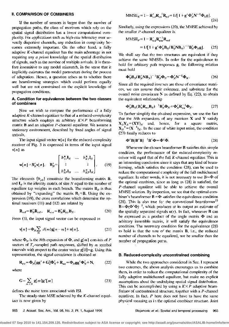
FIG. 7. Reduced-complexity multichannel DIE.
lution, which together with the underlying solution for the equalizer coefficients results in the minimal MSE, is equally good from the data-detection point of view.
{%}re=l: combiner ("beamformer") vectors with K ele- ments [ck.
{av}•= •: feedforward equalizer vectors with N elements [ai.p]i= -N l .....
b: feedback filter tap-weight vector with M elements. Assuming initially that the channel is fixed over some inter- val of time, one arrives at the optimal values of the receiver parameters. 9 Tracking of the optimal solution is accom- plished through a second-order gradient update for the mul- tichannel PLL and a double application of the RLS algorithm for obtaining the combinet coefficients and the coefficients of a multichannel DFE. Since the receiver parameters are optimized jointly, the overall a•daptation algorithm relies on the single error, e(n) = d(n) - d(n).
After compensating for the carrier phase distortions, the input signal samples at time nT are represented in the matrix form
IlL REDUCED-COMPLEXITY COHERENT COMBINING AND MULTICHANNEL DECISION-FEEDBACK EQUALIZATION
Because of the fundamental bandwidth limitations of the
UWA channels, high-speed communications over these chan- nels are inherently broadband. Hence, the full-complexity multichannel processor is the optimal choice for this case. Nevertheless, there are many practical advantages of using the "beamforming'Vequalization approach, even if it repre- sents a structurally suboptimal solution. Joint, unconstrained optimization of the spatial and temporal processor parts will ensure best performance of the chosen receiver structure, providing at the same time the needed reduction in complex- ity.
A reduced-complexity combiner can be used in conjunc- tion with any type of equalization method (linear, DFE or ML sequence estimation). We focus on a multichannel DFE, as it has proven to be an adequate choice for UWA channels characterized by extremely long impulse responses. 3
A. Receiver structure and algorithm
The complete structure of a practical receiver is shown in Fig. 7. The complex baseband input signals v•(t), k= 1 ..... K, are assumed to be bandlimited to the signaling rate l/T, and frame synchronized prior to sampling at twice the signaling rate (Ts= TI2). The front part of the practical receiver is equipped by a multichannel digital PLL which enables coherent combining. In cases when sufficient coher- ency between phases can be expected, phase correction can be performed at a point after combining using only P distinct phase estimates, or only a single phase estimate for all the channels can be used. These modifications are easy to carry out, and we concentrate on the case when all K phase esti- mates are computed. The KxP combiner performs spatial signal processing only, while temporal processing and final combining are performed in a bank of P feedforward equal- izers. Receiver parameters are updated once per symbol in- terval and the output of the linear part of the receiver is accordingly delivered to the feedback section. The receiver parameters to be optimized are defined below:
{ Ok}•= •: carder phase estimates,
v[,,] = v[,q ø,q, (32)
where
[ vk(nT+N1T]2)] /.
[ o•(nT-N2T/2)J (33)
The estimated data symbol, which is the input to the decision device, is given by
(34)
where z(n) represents the output of the linear part of the receiver after coherent combining, and fi(n) is the vector of M previously detected symbols stored in the feedback filter.
To obtain the carrier phase update equations it is useful to represent the variable z(n) as
K P
z(n) = • A•(n)e-JøL A•(n)= • * ' k=• p=l c•'t'at'v•[n]' (35)
This representation leads to the definition of the equivalent PLL detector outputs as
ffP•(n)=Im{A•(n)e-Jø*e*(n)}, k= 1 ..... K. (36)
Application of the stochastic gradient method yields the second-order carrier phase update equations
Ok(n) + g,a,k(n) + ø (37)
where Kf,.2 are the phase tracking constants. Similarly as in the full-complexity multichannel equalizer case, successful operation of the entire receiver strongly depends on the use of a second-order phase update in each of the K channels because of the severe phase fluctuations observed in many of the UWA channels?
MMSE optimization of the combinedequalizer param- eters requires that their equivalent input data vectors be de- fined. To do so, the variable z(n) is represented in two ways:
968 d. Acoust. Soc. Am., VoL 98, No. 2, Pt. 1, August 1995 Stojanovic et aL: Spatial and temporal processing 968
Downloaded 07 Sep 2010 to 141.154.209.135. Redistribution subject to ASA license or copyright; see http://asadl.org/journals/doc/ASALIB-home/info/terms.jsp

or
z(,)=[½,--.c,.] / " / L
=c'u[n],
l z(n)=[a'•'..a;] " =a'w[.]. (39)
The last expressions define the needed data vectors: u[n], the equivalent input to the combiner, and w[n], the equiva- lent input to the multichannel feedforward equalizen An RLS type of algorithm is used to update the combiner vector c(n), as directed by the input data u[n] and the error e(.). A second RLS update is used for the overall equalizer vector
f(n)=[ a(n) ] - b(n)]' (40) The input data for this update is a composite vector
Jw[n]l x[n] = J •(n)J' (41)
while the error remains the same. Assuming conect deci- sions, the desired MMSE solutions are given by
(42) and
f=[œ{x[n]x'[.]}]-'E{x[n]d*(n)}. (43)
Because there is no unique solution for the combiner/ equalizer coefficients, i.e., there are infinitely many solutions which lead to the global minimum of the MSE, proper ini- tialization must be used to set the starting point outside the region of a local minimum, e.g., not all the coefficients can be taken to be zero. Section II discussed possible solutions for the combinet which allow the equalizer coefficients to reach the jointly optimal solution in the case of a stationary environment with fixed and known angles of signal arrivals from multiple propagation paths. One of these solut tons is to choose each of the beamforming vectors ct, equal to the steering vector corresponding to the pth propagation path. However, since it is unlikely that such detailed krowledge about propagation conditions will be available at the re- ceiver, a more general initialization procedure is desired. Without showing its optimality, we have found the following initialization procedure to yield good results. At the start of adaptation, the combiner value is kept. fixed at t.n initial value, while the equalizer coefficients are updated from an all-zero condition. When the equalizer has converged (in a time interval corresponding to about twice the number of its taps), the beamformer begins its update. The initial values of the beamformer vectors c•, can be chosen to have all zeros and a one at position p. In this way, the beamformer initially passes to the equalizer the P arbitrarily chosen channels, without processing them. Later, it gains access to all K chan- nels, and begins their combining toward reducing the output MSE,
Since a separate update is used for the combinet and the equalizer, both the type of algorithm and the rate of its con-
vergence can be chcsen independently for the two updates, When very long channel responses are to be equalized, the multichannel DFE operates under a fast, numerically stable RLS? 3 On the other hand, the combiner's algorithm can be chosen even as standard RLS when KP is small enough to justify such choice. A choice of slightly different RLS for- getting factors, which allows faster convergence of the com- biner, may help improve the convergence rate of the overall algori thin.
With currently available processing speeds, and rela- tively low candidate symbol rates for long-range UWA te- lemetry, computational complexity of fast RLS algorithms allows a moderate number of channels to be processed in real-tone. (With 50 Mflop•, and equalizer lengths on the or- der of several tens, which is representative of 500-1000 symbols per second transmissions used in the experiment described below, less. than ten channels can theoretically be accommodated.) Although the increased number of channels allows shorter feedforward equalizers to be used, this does not alleviate the computational complexity problem. At shorter ranges, which support much higher data rates, the allowable number of channels reduces to only a few, making the use of reduced-complexity receivers, together with com- putationally efficient algorithms, imperative for processing a large number of chartnels.
Even when the computational complexity allows the use of optimal, lhll-complexity multichannel equalization, with increased number of taps to be updated, numerical stability imposes additional restrictions for use of the fastest RLS algorithms. To preserve stability, the forgetting factor of this algorithm has to be chosen •3 roughly as k>l-1/(2X total number of taps). While for a small number of taps, allowable values of h lie well within the region of practical interest (say, k•>0.98), for large number of taps, X becomes confined to relatively large wdues. (For 100 feedforward taps, 100 feedback taps, and say, 4 channels, it has to be •>0.999.) These values may be too high to provide adequate tracking for many of the UWA channels. In such a case, reduced- complexity multichannel !:rocessing provides an alternative to usiug other types cf RLS algorithms, such as lattice algo- rithms, which are inherently stable at the expense of in- creased complexity.
Finally, noise enhancement in large adaptive filters rep- resents a serious problem for full-complexity multichannel equalitation. 9 The reduced-complexity approach plays a vital role in this case, since it euables the multiple sensor signals to be combined prior to equalizatiom thus additionally ex- ploiting the spatial variabihty of the ocean channel. Equaliz- ing the so-obtained smaller number of signals has the impor- tant feature of keeping the noise enhancement at a minimum.
B. Experimental results
The reduced-complexity multichannel equalization method was tested for application in long-range UWA telem- etry. The algorithm described in this section was used to process the data obtained during a May 1992 experiment conducted by the Woods Hole Oceanographic Institution at the New England Continental Shelfi In this experiment, a vertical receiver array of 20 sensors was deployed between
969 J. Acoust. Soc. Am., Vol. 98, No. 2, Pt. 1, August 1995 Stojanovic et aL: Spatial and temporal processing 969
Downloaded 07 Sep 2010 to 141.154.209.135. Redistribution subject to ASA license or copyright; see http://asadl.org/journals/doc/ASALIB-home/info/terms.jsp

Range: 4• nautical m le5
o 25
delay [ms] 15 depth Ira)
FIG. 8. Long-range shallow water channel responses at different depths.
15 and 35 m in about 50-m deep water, and transmissions were conducted at ranges of 15 to 65 nautical miles. With a transmitter power of 193 dB re:/zPa, a 1-kHz carrier was used to transmit 4- and 8-PSK modulated signals at rates up to 1000 symbols per second (sps). A cosine roll-off filter with roll-off factor 0.5 was used to shape the signals at the trans- mitter.
As an example, we shall study the case of a 500 sps 8-PSK transmission over 48 nautical miles. Spatial variabil- ity of the long-range shallow water channel at 48 nautical miles is illustrated in Fig. 8. Shown in the figure are the instantaneous channel responses as a function of receiver depth. Clearly, there is a large variation in the shape of the channel response across the length of the array. The channel closest to the surface exhibits a relatively strong principal arrival, while as the depth is increased, a strong second, and eventually third reflections emerge.
Suppose that a full-complexity multichannel equalizer is restricted to operate in a configuration with only three of the 20 channels available. Because of the high spatial variability of the underwater channel, significantly different perfor- mance quality may result depending on the choice of the three channels. On the other hand, preceding the three- channel equalizer by an adaptive combiner which operates on all 20 channels increases the number of coefficients to be
computed per iteration only by 20X3. If each of the equal- izer branches has 60 taps, which is sufficient for about 60 ms of significant multipath at 500 sps, the increase in computa- tional complexity is the same as if one more channel were added to the full-complexity equalizer. However, while the fourth channel may contain a low-quality signal, the 20X3 combiner will adaptively form the best 3-channel combina- tion and pass it to the multichannel equalizer. The only con- dition that needs to be satisfied to achieve such performance is that the receiver parts be optimized jointly.
Considering the example of 500 sps 8-PSK transmission over 48 nautical miles, the performance of a full-complexity 3-channel equalizer ranges from the best-case output SNR of about 16 dB to cases where the three channels chosen con-
tained such low-quality signals that the algorithm was unable to maintain convergence after the training period. Combining both high- and low-quality channels in a jointly optimal
2O0O 4O0O [symbol intervals]
outscatter
0.5
2O0O 4O0O [symbot intervals]
receiver parameters: 500
N=60 ('I72) M=60 K=10 P-3 Le=0.998 Lc=0.99 Kf1=0.0005 Kf2=Se-05
Pe.-O SNRout--18.58dB 2.• 0 2
FIG. 9. Receiver performance at 48 nautical miles, 500 sps.
10x3 beamformer and a 3-channel DFE, resulted in the per- formance shown in Fig. 9. Shown in the figure are the esti- mated MSE, the carrier phases in all ten channels, and the output scatter plot of the estimated data symbols. Receiver parameters are listed in the figure (Lc, • denote the forgetting factors of the combiner and the equalizer RLS algorithms, respectively). In this configuration, the reduced-complexity receiver yielded an improvement of 2 dB in the output SNR over the best case 3-channel DFE performance. No errors were detected in a data block of 10 000 symbols. In addition, the receiver performance was insensitive to the choice of the ten input channels among the 20 available channels.
Excellent results were also achieved with 1000-sps sig- naling. Figure 10 illustrates the performance of a 7X3 com- biner and 3-channel equalizer at 2000 bits per second signal- ing over 48 nautical miles. The results for QPSK are summarized in Fig. 11 which shows receiver performance in several configurations. The output SNR is shown as a func-
10
rnse •ase Ifad]
20OO 400O [symbol intentafs]
out.scatter
0.6
0.4 ld-• 0.2
-0.2
o41 o 2cx)o 40oo
[symbol intervals]
receiver p•ameters: 1000 sps
N-so (TRY) M-leO K 7P-3 Le=0.998 Lc-0.99 Kfl=0.0001 Kf2-1e-05
Pe--0 SNRout~15.66dB
FIG. 10. Receiver performance at 48 naulical miles, 1000 sps.
970 J. Acoust. Soc. Am., Vol. 98, No. 2, Pt. 1, August 1995 Stojanovic et al.: Spatial and temporal processing 970
Downloaded 07 Sep 2010 to 141.154.209.135. Redistribution subject to ASA license or copyright; see http://asadl.org/journals/doc/ASALIB-home/info/terms.jsp

FIG. I I. Output SNR as a function of the reduced number of equalizer channels P.
tion of the reduced number of channels, P, which is varied
from P=! to P=K=7. The parameter on the cur•es is the total number of equalizer taps per channel, N. The length of the feedback filter is keIJt constant, M= 100. Naturally, per- formonce improves as P increases. However, what is inter- esting to note is that there, exists a form of saturation in peff,'ormance: Already for P=3 the output SNR •e. aches a value which remains almost constant with further increase in
P. While an increase Jn P from P=I to P=3 lesults in
dramatic improvement in performance, changing the number of equalizer channels from 3 to 7 results in the total fluctua- tion of the output SNR of less than 0.5 dB for all the equal- izer lengths examined. This fluctuation is insignificant for the overall receW6r performance at the given values of output SNR. The corresponding change in complexity, on Ihe other hand, is consi4ffrable: Using a P-channel configuration in- stead of the "optimal" full-complexity configuration, re- duces the total number of filter coefficients by about KIP at large values of N. This bring• a significant reduction in com- plexity when the value of'P at which "saturation" is reached ia low: at N,=60, only 200 taps are needed in the 3-channel configuration as opposed to 420 taps of the full-complexity structure. No degradation in performance accompanies this complexity reduction. In fact, careful examination of the out- put SNR behavior reveals that as N increases, the SNR ex- hibits a slight degradation after a certain value of P. Such behavior is caused by noise enhancement. Its effect is more pronoqnced for longer adaptive filters, as illustrated by the fact tha•t only the N=20 of all the curves presented does not reach a regime where noise enhancement begins to influence performance. Additional degradation may occur in perfor- mance of high-complexity structures on rapidly varying channels when stability constraints of the fast numerically stable RLS •3 must be imposed on the equalizer forgetting factor. This degradation, specific only to certain algorithms, is not included in performance results of Fig. 11. The value of the equalizer forgetting factor was chosen to be L• =0.998 in all of tbe cases presented.
The results obtained demonstrate several important fea-
tures of simultaneous reduced-complexity combining and equalization. First, the capability to adaplively choose the best P-channel combination among the K channels available eliminates the strong spatial dependency observed in both the single-channel and thg full-complexity multichannel re- ceiver. Second, a multichannel processing gain is obtained over the same-size, full-complexity multichannel receiver, thus demonstrating the capability to additionally exploit spa- tial diversity of the oce• multipath at no increase in com- putational cost or noise enhancement. Finally, comparison of the performance of reduced-complexity structures to that of their full-complexity counterparts which operate on all the avaiktble channels shows the saturation in the output SNR.
Hence, the receiver peffo. rms equally well in a configuration that has a small nurrber of equalizer channels.
IV. SUMMARY AND CONCLUSIONS
High-speed UWA coramunication systems, being inher- ently broad,band .due to tl'.e larg• energy absorption at high freqhencies, require. computationally intensive receiver algo- rithms'for multichannel, spatial and temporal signal process- ing. The use of lfirgh brnadband array processors implies problems of noise enhancement and convergence rate trade- offs ia fast transversal filters. In addition to these problems. meeting the computational needs of the receiver algorithm will become a serious prcblem for multichannel processing in medium and short-range UWA communications where much higher band•.idths than those of the long-range telem- etry channels are'available:.
Jhere is a certain gap, if only in terminology, between approaching the problem of multichannel signal processing from the viewpoint of diversity combining and that of beam- formiag. With the goal 05 making large arrays compatible with powerful, but complex time-processing algorithms, we attempted to bridge this gz.p by examining the role of beam- forming in the detection ot' multipath-corrupted communica- tion signals.
'[he optimal receivers. nonlinear and linear, consist of an identical combiner, while all the subsequent processing is performed in a single, discrete-time channel. If there exists a relationship between the signals at different sensors, such as in the narrow-band case, the optimal combiner can be iden- tified as a beamformer and a bank of path-matched filters. In contrast to conventional multipath suppression techniques, it is designed to make ase of all signal reflections rather than treating them as unwanted interference.
The optimal combiner gives rise to two classes of adap- tive implementations. The first class makes no assumptions about the relationship between the received signals, while the second class explicitly use• knowledge of the angles of sig- nal ar-ivals. The receiver of the second class relies heavily on the assumption that the: spatial distribution of signals is known and will be sensitive to any model mismatch. The receiver of the first class, while independent of the existence of any spatial distribution of signals, has a very high compu- tational complexity when a large array is used together with long equalizers.
To compare the •pproaches considered, a simple condi- tion for equality between tlae two classes of receivers is ob-
971 d. Acoust. Soc. Am., Vol. 98, No. 2, Pt. 1, August 1995 Stojanovic et aL: Spatial and temporal processing 971
Downloaded 07 Sep 2010 to 141.154.209.135. Redistribution subject to ASA license or copyright; see http://asadl.org/journals/doc/ASALIB-home/info/terms.jsp

tained. It shows that when the number of sensors is larger than the number of propagation paths, the beamforming in- terpretation of the optimal combinet offers the possibility of reducing the complexity of a pure diversity combinet, while retaining the same performance. Split beamforming, in which parts of the array are dedicated to beamforming to- ward individual propagation paths, cannot achieve the per- formance of a full-matrix beamformer. Both the conventional
and the "optimal" beamformer, on the other hand, achieve the same performance as the fully adaptive multichannel equalizer. Hence, proper spatial combining offers the means of reducing the sometimes unacceptable computational com- plexity of pure diversity combining. For an unknown spatial signal distribution, this is accomplished by jointly optimizing an unconstrained matrix beamformer and a reduced-
complexity multichannel equalizer. In practice, such an ap- proach is preferable to the explicit angle of arrival tracking because it does not require accurate initial estimates, nor does it rely on any assumptions such as plane-wave propa- gation, and therefore eliminates the sensitivity to modeling errors.
A practical receiver proposed uses this type of combin- ing simultaneously with multichannel carder phase recovery and decision-feedback equalization. Regardless of the spe- cific spatial signal distribution, combining a large number of array signals into a smaller number which are then processed in a multichannel equalizer offers a solution for reducing the receiver complexity without sacrificing the available spatial diversity gain. Joint optirnjzation of the beamformer, the multichannel carrier phase estimator and the DFE provides compatibility of coherent spatial and temporal MMSE com- bining.
Experimental results demonstrate the excellent perfor- mance of the reduced-complexity adaptive combining/ equalization algorithm at 50 nautical miles in shallow water with data rates up to 2000 bits per second. Besides providing an additional multichannel processing gain at little or no in- crease iri computational complexity, the receiver overcomes spatial dependency of previous multichannel equalizers with- out requiring a priori knowledge of propagation conditions.
Further potential of reduced-complexity multichannel equalization will become apparent in the case of multiuser signal reception where in addition to multipath recombining, the beamformer will accomplish spatial separation of the de- sired signal from multiple-access interference.
ACKNOWLEDGMENTS
This work was supported in part by the ARPA Marine Systems Technology Office, Grant No. MDA-972-9 l-J-1004.
•J. Catipovic and L. Freitag, "High data rate acoustic telemetry for moving ROV's in a fading multipath shallow water environment," Proc. 7th Inter- national Symposium on Unmanned Uutethered Submersible Technologies, 269-303 (1990).
2j. Fischer, K. Bennet, S. Reible, J. Cafarella, and I. Yao, "A high rate, underwater acoustic data communications transceiver," in Proc.
Oceans'92, Newport, RI (IEEE, New York, 1992), pp. 571-576. 3M. Stojanovic, J. Catipovic, and J. Proakis, "Phase coherent digital com-
munications for underwater acoustic communications." IEEE J. Oceanic Eng. OE-19, 100-Ill (1994).
4A. Quazi and W. Konrad, "Underwater acoustic communications," IEEE Commun. Mag. 20, 24-29 0982).
SR. Coates, "Underwater acoustic communications," in Proc. Oceans'93, Victoria, Canada (IEEE, New York, 19931, III420-425.
6 A. Baggaroer, "Acoustic telemetry--an overview," J. Oceanic Eng. OE-9, 229-235 (1984).
7L. Wu and A. Zielinski, "Multipath rejection using narrow beam acoustic link," in Proc. Oceans '88, Baltimore, MD (IEEE, New York, 1988), pp. 287-290.
8j. Catipovic and L. Freitag, "Spatial diversity processing for underwater acoustic telemetry," IEEE J. Oceanic Eng. OE-15, 205-216 (1991).
9M. Stojanovic, J. Catipovic, and J. ProaMs, "Adaptive multichannel com- bining and equalization for underwater acoustic communications," J. Acoust. Soc. Am. 94, 1621-1631 (1993}.
mQ. Wen and J. Ritcey, "Spatial equalization for underwater acoustic com- munications," in Proc. 26th Asilomar Conference on Signals, Systems and Computers, 1132-1136 (1992).
UR. Gooch and B. Sublett, "Joint spatial and temporal equalization in a decision-directed adaptive antenna system," in Proc. 22nd Asilomar Con- ference on Signals, Systems and Computers, 255-259 (1988).
•20. Hinton, G. How•, and A. Adams, "An adaptive, high bit rate, sub-sea communications system." Proceedings of the European Conference on Underwater Acoustics, Brussels, Belgium, edited by M. Weydert (Elsevier Applied Science, Amsterdam, 1992), pp. 75-79.
13D. Slock and T. Kailath, "Numerically stable fast transversal filters for recurslye least squares adaptive filtering." IEEE Trans. Signal Process. SP-39, 92-114 (1991).
14p. Bragard and G. Jourdain, "A fast self-optimized LMS algorithm for nonstationary identification. Application to underwater equalization," in Proc. ICASSP'90, 1425-1428 (1990}.
ISR. Monzingo and T Miller, Introduction to Adaptive Arrays (Wiley, New York. 1980}.
,tp. Monsen, "Theoretical and measured performance of a DFE modem on a fading multipath channel," IEEE Trans. Commun. COM-25, 1144- 1153 (1977).
17p. Balaban and J. Salz, "Optimum diversity combining and qualization in digital data transmission with applications to cellular mobile radio," IEEE Trans. Common. COM-40, 885-895 (1992).
•s D. Chapman. "Partial adaptivity for the large array," IEEE Trans. Antenna Pmpag. AP-24. 685-696 {1976).
972 J. Acoust. Soc. Am., Vol. 98, No. 2, Pt. 1, August 1995 Stojanovic el al.: Spatial and temporal processing 972
Downloaded 07 Sep 2010 to 141.154.209.135. Redistribution subject to ASA license or copyright; see http://asadl.org/journals/doc/ASALIB-home/info/terms.jsp