reducing time to market: parallel software development...
TRANSCRIPT
Reducing Time to Market: Parallel Software Development with Emulation and Simulation Tools for Mobile Extreme Convergence (MXC) Architectures
Software is everywhere and it dominates our product development cycle. What if your software was tested and working before you received first silicon samples? What would that do to your product’s delivery schedule?
Document Number: MXCSWDEVWP Rev 4
Freescale Semiconductor, Inc.
2Reducing Time to Market, Rev 4Freescale Semiconductor, Inc.
Contents
1.0 Introduction ......................................................................................3
2.0 Freescale’s MXC Architecture ..........................................................3
2.1 Advantages of the MXC Architecture for Developers ...............3
3.0 Introduction to Parallel Development ..............................................5
4.0 Virtual Prototyping ...........................................................................7
4.1 Virtual Prototyping Components ...............................................8
4.2 Benefits ......................................................................................8
4.3 Better Than the Real Thing? ......................................................9
4.4 The VPMX Virtual Platform Family .............................................9
4.4.1 Software Development Tool Integration ...............................10
4.4.2 Porting an Open OS for MXC Architecture with VPMXC .....11
4.15 Virtual Prototyping Conclusion ..............................................12
5.0 Incisive Emulation Tools .................................................................12
5.1 Hardware/Software Co-Verification ........................................13
5.2 Palladium Technology .............................................................13
5.3 Debugging MXC Software Using Palladium ...........................14
5.4 Remote and Multi-User Capabilities ......................................15
6.0 Conclusion .....................................................................................16
7.0 Resources .....................................................................................17

3Reducing Time to Market, Rev 4Freescale Semiconductor, Inc.
1. IntroductionIn 2003, converged mobile devices represented about 3 percent of the 500 million mobile phones sold worldwide and they are expected to grow at triple-digit year-over-year growth rates. More than half of all mobile phones sold today include a color display and a digital camera.
The implementation of more advanced features such as accelerated 2-D and 3-D graphics, mobile multimedia, mobile IP and personal entertainment raises the performance requirements of these models while market pressures force prices downward. At the same time, the trend is to drive more of these features into lower-cost phone models. Wireless operators require a broader base of phones with new features to encourage the consumption of new services, including those enabled by newer technologies such as EDGE and 3G.
The adoption of these features is made possible by rapid advances in semiconductor technology, micro-architectures and embedded systems. Device manufacturers are in a race to create devices with the latest technology and bring them to the market before their competitors. While complexity is increased by new features and advanced software requirements, the pressure is higher than ever to reduce the time required for designing, prototyping, testing and manufacturing.
2. Freescale’s Mobile Extreme Convergence (MXC) ArchitectureIn October of 2003 Freescale Semiconductor announced an advanced, exciting architecture to power future mobile devices, called Mobile Extreme Convergence (MXC). This new architecture provides all the core features of a smartphone in a postage-stamp-sized chip, enabling more powerful devices at lower costs.
With more than 50 years of wireless know-how, Freescale* is uniquely qualified to deliver a major rethinking of wireless and mobile, smart handheld architectures. MXC is a comprehensive smartphone platform on a single chip with key benefits for device manufacturers.
The MXC architecture:
Being able to offer devices that leverage MXC’s innovations can constitute a key competitive advantage. Designers are faced with serious project delays if they wait for first silicon to begin software development and testing. Increasingly they are turning to simulation and emulation tools, including hardware/software co-verification—concurrently verifying hardware and software components of the system design—to meet demanding time-to-market requirements. Concurrent verification and instruction set simulation for application processors allow software development, verification and debugging to begin before silicon is available, potentially shaving months off the product development schedule.
4Reducing Time to Market, Rev 4Freescale Semiconductor, Inc.
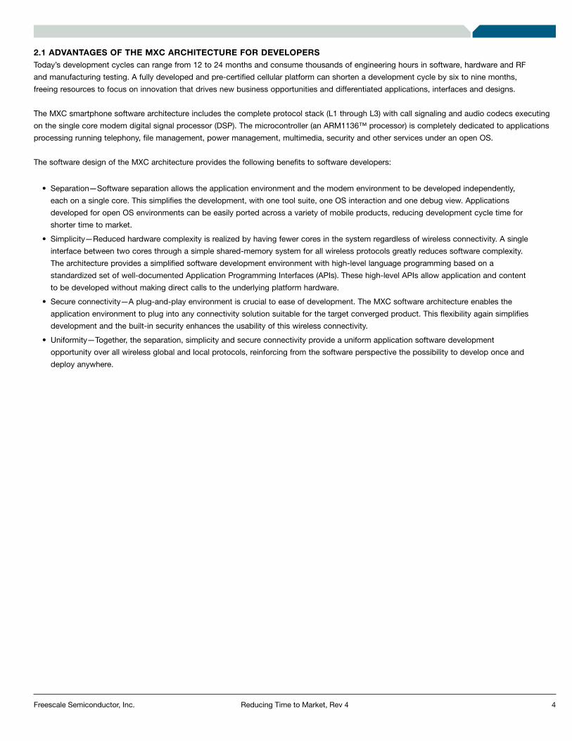
2.1 ADVANTAGES OF THE MXC ARCHITECTURE FOR DEVELOPERSToday’s development cycles can range from 12 to 24 months and consume thousands of engineering hours in software, hardware and RF and manufacturing testing. A fully developed and pre-certified cellular platform can shorten a development cycle by six to nine months, freeing resources to focus on innovation that drives new business opportunities and differentiated applications, interfaces and designs.
The MXC smartphone software architecture includes the complete protocol stack (L1 through L3) with call signaling and audio codecs executing on the single core modem digital signal processor (DSP). The microcontroller (an ARM1136™ processor) is completely dedicated to applications processing running telephony, file management, power management, multimedia, security and other services under an open OS.
The software design of the MXC architecture provides the following benefits to software developers:
each on a single core. This simplifies the development, with one tool suite, one OS interaction and one debug view. Applications developed for open OS environments can be easily ported across a variety of mobile products, reducing development cycle time for shorter time to market.
interface between two cores through a simple shared-memory system for all wireless protocols greatly reduces software complexity. The architecture provides a simplified software development environment with high-level language programming based on a standardized set of well-documented Application Programming Interfaces (APIs). These high-level APIs allow application and content to be developed without making direct calls to the underlying platform hardware.
application environment to plug into any connectivity solution suitable for the target converged product. This flexibility again simplifies development and the built-in security enhances the usability of this wireless connectivity.
opportunity over all wireless global and local protocols, reinforcing from the software perspective the possibility to develop once and deploy anywhere.

5Reducing Time to Market, Rev 4Freescale Semiconductor, Inc.
3. Introduction to Parallel Development
Concentrating on innovations that help developers, Freescale works with industry leaders to provide a model for development that can signifi-cantly reduce the time it takes to create a new device by enabling the development of software and hardware in parallel, months before the availability of silicon. The goal is to accelerate the development process by creating synergies with leading-edge technology vendors: simulation and emulation acceleration from Cadence, Virtual platforms from Virtio and development tools from Metrowerks.
As software content continues to grow and as devices become more complex, product development cycles are getting longer. In the past, device manufacturers had to wait for silicon availability to have a platform for software verification. This arrangement makes the hardware and system software debugging tasks largely sequential and increases the product’s development time. It also means that a serious system problem may not be found until late in the project, potentially resulting in months of delays. See Figure 1
Figure 1. Traditional Development Process.
HS-DPCCHPhysical channel carrying feedback info
from mobile to base stationACK/NACK and CQI
Silicon Development
Baseband Radio Codec Development
(DSP Core)
TIME
Dev
ice
Con
cept
App
licat
ion
Dev
elop
men
tO
S P
ort,
Dev
ice
Driv
er, U
I
Har
dwar
e P
roto
type
with
firs
t sili
con
HW
/SW
Inte
grat
ion,
Test
ing
and
Deb
uggi
ng
Man
fact
ure
FirstSilicon Standard Development Process
6Reducing Time to Market, Rev 4Freescale Semiconductor, Inc.
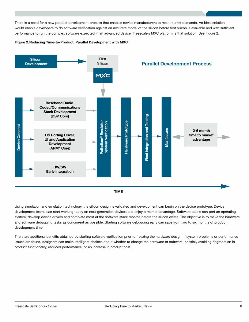
There is a need for a new product development process that enables device manufacturers to meet market demands. An ideal solution would enable developers to do software verification against an accurate model of the silicon before first silicon is available and with sufficient performance to run the complex software expected in an advanced device. Freescale’s MXC platform is that solution. See Figure 2.
Figure 2. Reducing Time-to-Product: Parallel Development with MXC
Using simulation and emulation technology, the silicon design is validated and development can begin on the device prototype. Device development teams can start working today on next-generation devices and enjoy a market advantage. Software teams can port an operating system, develop device drivers and complete most of the software stack months before the silicon exists. The objective is to make the hardware and software debugging tasks as concurrent as possible. Starting software debugging early can save from two to six months of product development time.
There are additional benefits obtained by starting software verification prior to freezing the hardware design. If system problems or performance issues are found, designers can make intelligent choices about whether to change the hardware or software, possibly avoiding degradation in product functionality, reduced performance, or an increase in product cost.
Parallel Development Process
HS-DPCCHPhysical channel carrying feedback info
from mobile to base stationACK/NACK and CQI
Silicon Development
Baseband Radio Codec/Communications
Stack Development(DSP Core)
2-6 monthtime to market
advantageOS Porting Driver,UI and Application
Development(ARM® Core)
HW/SWEarly Integration
TIME
Dev
ice
Con
cept
Pal
ladi
um® E
mul
ator
Syst
em V
erifi
catio
n
Har
dwar
e P
roto
type
Fina
l Int
egra
tion
and
Test
ing
Man
fact
ure
FirstSilicon

7Reducing Time to Market, Rev 4Freescale Semiconductor, Inc.
4. Virtual PrototypingSoaring personal computer clock speeds allow for the ability to emulate hardware devices in software, with performance approaching that of the physical devices themselves. Virtual prototyping technology enables the creation of high-performance software models of embedded systems that are so complete that they fully mirror the hardware functionality. The models are called virtual platforms and are produced by combining high-speed processor instruction-set simulators and high-level, fully functional C/C++ models of the hardware building blocks. The result is a high-level model of hardware that is sophisticated enough for a software developer to substitute for the physical device.
Using a virtual platform, software teams can start developing, integrating and testing software code long before silicon is available. This technology truly enables concurrent software development at all levels, including development of ROM code, firmware code, device drivers, OS porting, middleware and applications.
Through the close integration of commercial, embedded software development tools and a virtual platform, a software developer has a complete, stable, desktop-based software environment to develop and debug software functionality and hardware-software interaction. With an execution speed of over 40 million instructions per second, the platforms are capable of booting a wide range of application code including operating systems such as Symbian OS™, Windows CE®, Palm OS® and Linux® OS in a matter of seconds.
For Freescale’s i.MX devices, software development can start today through the availability of the Virtio VPMX virtual platform family. Figure 3, provides an overview of Virtio’s virtual prototyping technology.
Figure 3. Virtual Prototyping Technology Diagram
HS-DPCCHPhysical channel carrying feedback info
from mobile to base stationACK/NACK and CQI
ProcessorModel
C/C++Hardware
Model
SoftwareDebugger
Platform EditorRun-Time Control
Hardware Debugger
Virtio Innovator (IDE)
Debug Protocol Run-Time Control
UI Engine
Audio
Camera
Ethernet
Serial
Virtual I/O
UI ActiveElements
Magic-C DiscreteEvent Simulator
Simulation InfrastructureVirtuo™ Runtime Environment (VRE)
Magic-CGraphical C/C++Hardware Model
Virtual Platform Models

8Reducing Time to Market, Rev 4Freescale Semiconductor, Inc.
4.1 VIRTUAL PROTOTYPING COMPONENTS
Conceptually, a virtual platform builds upon the following components:
prototype hardware.
can be captured as high-level C/C++ models and compiled and executed on top of a system simulator to capture the hardware portion of a design.
manipulation.
With technology components like these in place, binary compatibility with a physical device is achieved at execution speeds that make it a realistic development target for software developers.
4.2 BENEFITS
Virtual platforms effectively help lower risk and decrease time to market by supporting early software development and integration. The major benefits of virtual system prototyping include:
hardware at speeds of several tens of millions of cycles per second. Early software development can take place well in advance of even a first silicon prototype, enabling parallel hardware development. These platforms can be made available typically two to three months after an architectural specification is completed and in parallel with HDL design, which truly distinguishes a virtual platform from other pre-silicon solutions. The advantage of early virtual hardware targets is continuous hardware/software integration. A meeting of software and hardware near the end of silicon development is no longer practical in today’s fast-paced markets.
hardware, not limiting that ability to available pins or the JTAG interface on the physical prototype. In addition, a virtual platform can be stopped at any time and inspected. This capability is especially useful when designing complex software components like device drivers that touch the hardware-software boundary. Another feature contributing to higher productivity is execution predictability, which allows consistent reproduction of certain scenarios for testing purposes. In addition, virtual platforms offer a faster turnaround time through instantaneous download of RAM, ROM and Flash memories.
Accurate prototypes give access to unique hardware details that are vital for optimizing software for the devices. These hardware details include insight into specialized CPU instructions and access to the hardware accelerator and DMA engine, leading to more optimized software. In addition, prototypes allow developers to run target software as is, with no modifications, easing the identification of software bugs. Finding bugs earlier results in higher quality code.
miscommunication between internal teams, customers and design teams. A virtual platform allows all team members to participate in design and system validation while building confidence in the foundation on which the software operates.
functionality of upcoming offerings. By engaging the entire development chain early, including independent software vendors (ISVs), device manufacturers and finally independent application developers, virtual platforms accelerate acceptance and commitment to the upcoming platform.
9Reducing Time to Market, Rev 4Freescale Semiconductor, Inc.
4.3 BETTER THAN THE REAL THING?
Virtual prototypes have a number of unique advantages over their physical counterparts. Simulations provide unsurpassed flexibility and avoid board and hardware iterations, which are typical during the pre-silicon hardware phase where design changes are common. Such features, along with others such as intact system state preservation whenever the CPU is stopped, help improve development productivity. A virtual solution is also cost-effective compared to physical solutions and much easier to distribute and deploy. One of the most important differentiating capabilities is automated testing. By using a virtual platform, you can automate tests of your software using either built-in or desktop testing tools and create regressions to assure that changes do not diminish software functionality.
Virtual platforms have changed the way embedded software is developed, integrated and tested by providing early software development and hardware-software integration, easy configuration, flexible debug and modification, complete visibility into both the hardware and software functionality, full control and electronic distribution.
4.4 THE VPMX VIRTUAL PLATFORM FAMILY
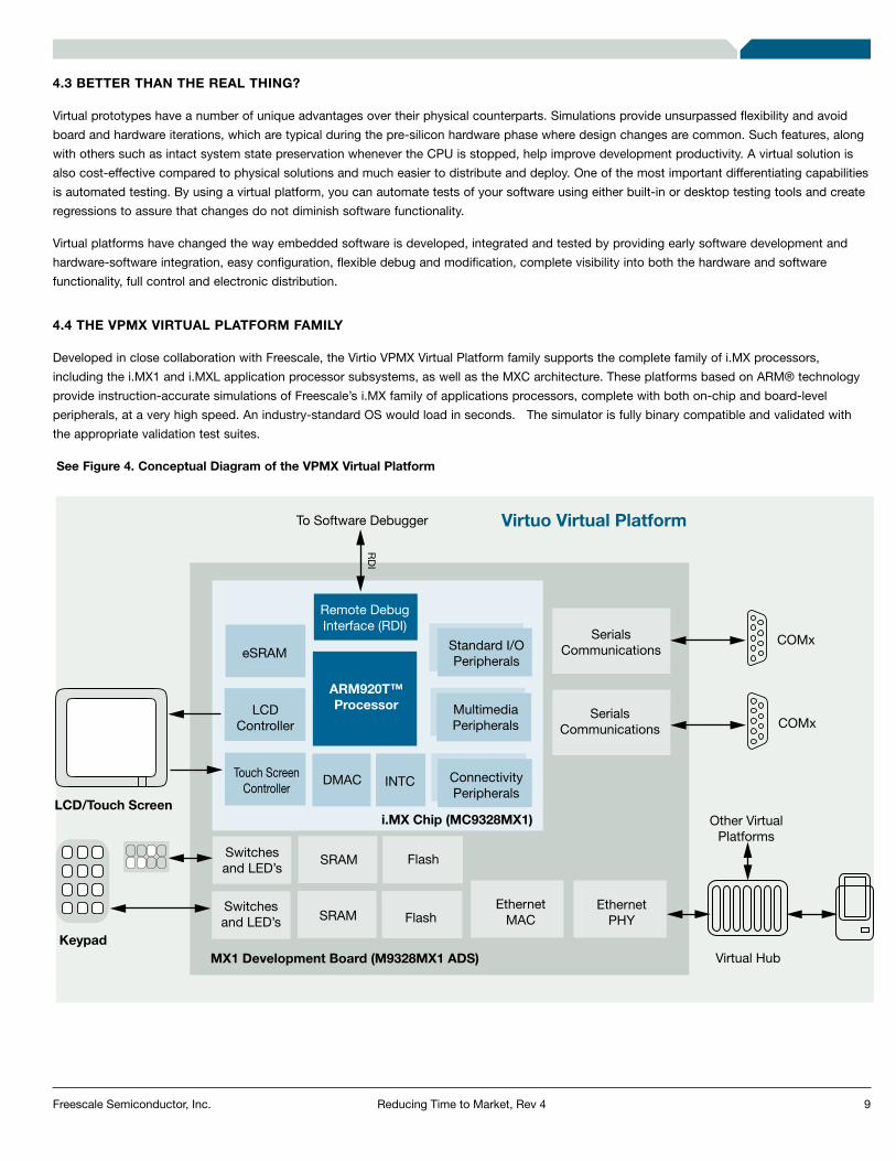
Developed in close collaboration with Freescale, the Virtio VPMX Virtual Platform family supports the complete family of i.MX processors, including the i.MX1 and i.MXL application processor subsystems, as well as the MXC architecture. These platforms based on ARM® technology provide instruction-accurate simulations of Freescale’s i.MX family of applications processors, complete with both on-chip and board-level peripherals, at a very high speed. An industry-standard OS would load in seconds. The simulator is fully binary compatible and validated with the appropriate validation test suites.
See Figure 4. Conceptual Diagram of the VPMX Virtual Platform
Virtuo Virtual Platform
eSRAM
LCDController
DMAC INTC ConnectivityPeripherals
Switchesand LED’s
LCD/Touch Screen
To Software Debugger
Keypad
Switchesand LED’s
SRAM Flash
SRAM FlashEthernet
MACEthernet
PHY
Virtual Hub
i.MX Chip (MC9328MX1) Other VirtualPlatforms
COMx
COMx
RD
I
MX1 Development Board (M9328MX1 ADS)
MultimediaPeripherals
Standard I/OPeripherals
ARM920T™Processor
Remote DebugInterface (RDI)
SerialsCommunications
SerialsCommunications
Touch ScreenController
10Reducing Time to Market, Rev 4Freescale Semiconductor, Inc.
For example, the VPMX platform, a model of the i.MX1 processor, contains ADS board-level and i.MX SoC peripherals and supports virtual physical connections. Serial and Ethernet ports in the development desktop are available as if they were part of the board. Through the additional Platform Development (PDK) product, developers can customize the board-level simulator with their own hardware peripherals and skins. This ability allows i.MX chipset users and device manufacturers to quickly morph the standard simulator into a real device simulator for pre-device software development.
4.4.1 SOFTWARE DEVELOPMENT TOOL INTEGRATION
The VPMX family works seamlessly with industry-standard development tools, requiring no new tools to be learned and no new debug infrastructure to be developed. A low-level target connection, similar to a physical JTAG connection, is enabled through the support of a standard ARM Remote Debugger Interface (RDI). This setup allows low-level target control over the ARM CPU, supporting all typical debug operations such as single-stepping, memory breakpoints and watchpoints and register and memory access. A second type of debug connection, called remote target connection, is supported through virtual I/O capability. For example, using virtual Ethernet, a TCP/IP-based connection between a desktop debugger and a debug daemon can be established. No changes are required in the debugger or the debug daemon.
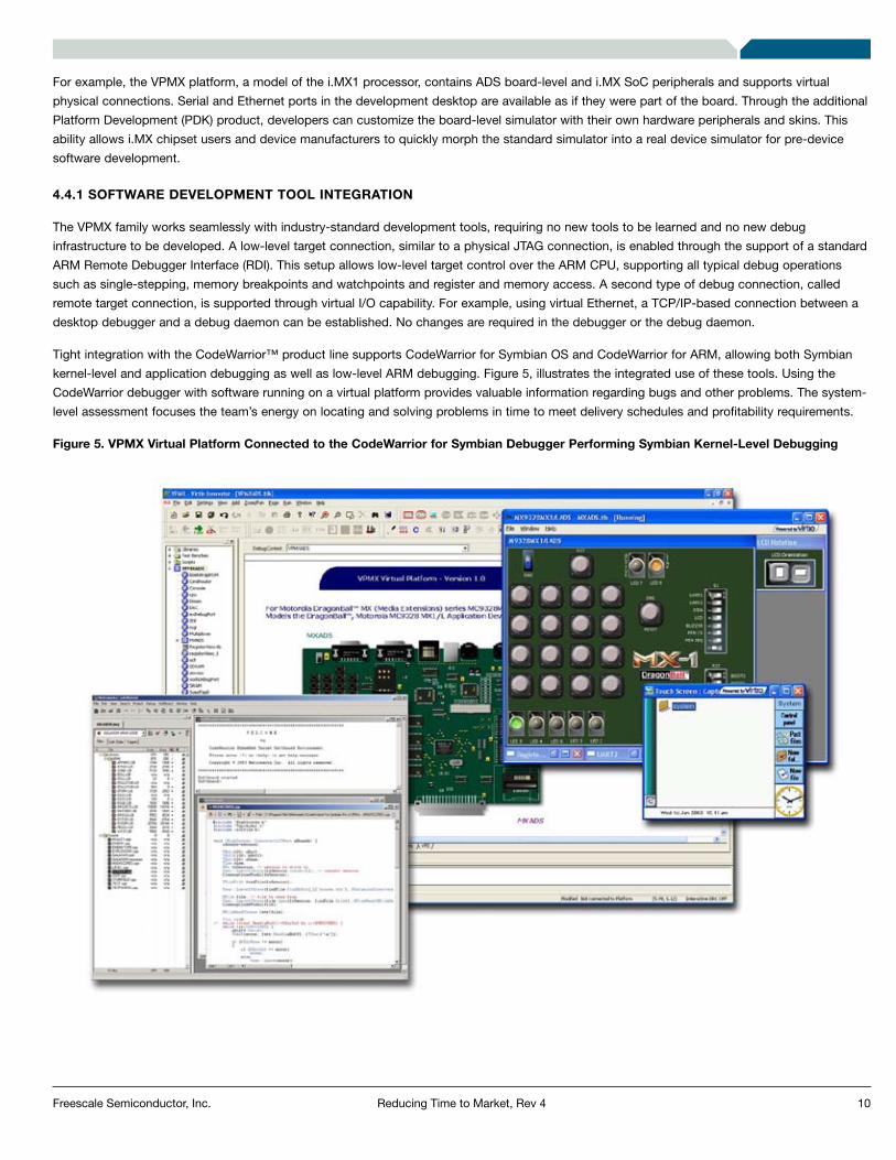
Tight integration with the CodeWarrior™ product line supports CodeWarrior for Symbian OS and CodeWarrior for ARM, allowing both Symbian kernel-level and application debugging as well as low-level ARM debugging. Figure 5, illustrates the integrated use of these tools. Using the CodeWarrior debugger with software running on a virtual platform provides valuable information regarding bugs and other problems. The system-level assessment focuses the team’s energy on locating and solving problems in time to meet delivery schedules and profitability requirements.
Figure 5. VPMX Virtual Platform Connected to the CodeWarrior for Symbian Debugger Performing Symbian Kernel-Level Debugging
11Reducing Time to Market, Rev 4Freescale Semiconductor, Inc.
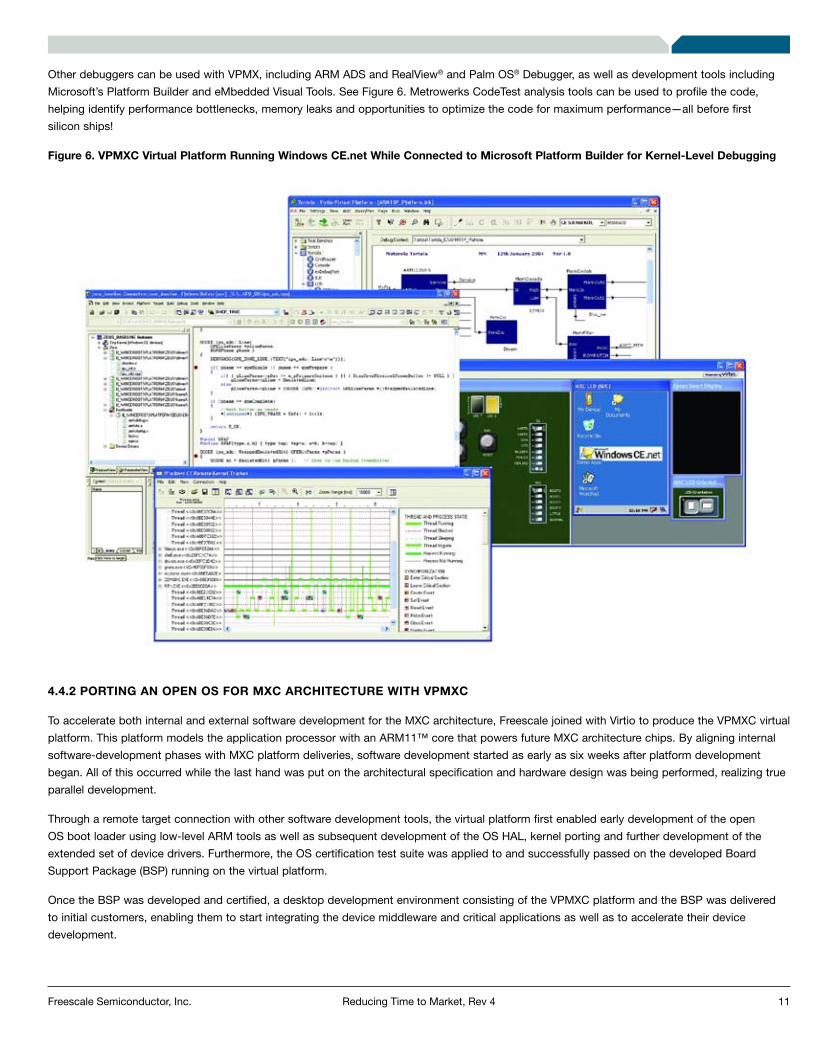
Other debuggers can be used with VPMX, including ARM ADS and RealView® and Palm OS® Debugger, as well as development tools including Microsoft’s Platform Builder and eMbedded Visual Tools. See Figure 6. Metrowerks CodeTest analysis tools can be used to profile the code, helping identify performance bottlenecks, memory leaks and opportunities to optimize the code for maximum performance—all before first silicon ships!
Figure 6. VPMXC Virtual Platform Running Windows CE.net While Connected to Microsoft Platform Builder for Kernel-Level Debugging
4.4.2 PORTING AN OPEN OS FOR MXC ARCHITECTURE WITH VPMXC
To accelerate both internal and external software development for the MXC architecture, Freescale joined with Virtio to produce the VPMXC virtual platform. This platform models the application processor with an ARM11™ core that powers future MXC architecture chips. By aligning internal software-development phases with MXC platform deliveries, software development started as early as six weeks after platform development began. All of this occurred while the last hand was put on the architectural specification and hardware design was being performed, realizing true parallel development.
Through a remote target connection with other software development tools, the virtual platform first enabled early development of the open OS boot loader using low-level ARM tools as well as subsequent development of the OS HAL, kernel porting and further development of the extended set of device drivers. Furthermore, the OS certification test suite was applied to and successfully passed on the developed Board Support Package (BSP) running on the virtual platform.
Once the BSP was developed and certified, a desktop development environment consisting of the VPMXC platform and the BSP was delivered to initial customers, enabling them to start integrating the device middleware and critical applications as well as to accelerate their device development.

12Reducing Time to Market, Rev 4Freescale Semiconductor, Inc.
4.5 VIRTUAL PROTOTYPING CONCLUSION
In summary, a virtual platform truly enables software engineers to start their software development as early as possible and minimize problems related to hardware-software integration. Development begins long before the hardware is in place and without expensive instrumentation tools. A powerful paradigm of continuous integration of hardware and software emerges, where every developer develops on the real emulated target, with actual target development tools. This paradigm avoids the typical, time-consuming, post-development integration phase and it results in higher quality, more timely products.
5. Incisive Emulation ToolsThe software content of all electronic products is growing exponentially and is quickly becoming the determining factor in product release cycles. First silicon is no longer the critical issue. Today, it’s first working software.
An instruction set simulator (ISS) is a very useful tool for porting, developing and testing an operating system, drivers and application software. However, verifying hardware and system software separately could leave some of the most difficult problems to the most critical part of the project: final integration. It is a great advantage to be able to test hardware and system software together—hardware/software co-verification—and to do it as early in the project as possible.
Freescale has partnered with Cadence for its Incisive Palladium emulation technology. The Palladium emulator can significantly reduce the time it takes device manufacturers to test a complete system by emulating all the parts of a complex System on a Chip (SoC) including the DSP core, the ARM core for application processing, memory and other subsystems.
In addition, system software is tested with real peripherals (such as keypad, display and SIM card) that are connected to the emulator using a development board. This approach gives the closest level of simulation possible, accurately reflecting the final device and resulting in high confidence that there will be no surprises in final integration.
The Palladium emulator includes a model of the MXC architecture that is expected to provide OEMs, ODMs and other device developers with the tools to verify their software months before silicon availability—and at speeds that allow testing of complete applications, not just drivers and diagnostics. These tools will result in significantly compressed overall product development cycles and the ability to bring products to market sooner, generating greater top-line revenue.
Early software integration on real hardware provides enormous value:

13Reducing Time to Market, Rev 4Freescale Semiconductor, Inc.
As mentioned earlier, increasing time-to-market pressures and increasing levels of software content demand that device manufacturers shrink their development cycle in spite of increasing software content and complexity. What makes Palladium a perfect fit to solve this problem is that, in addition to being the fastest ASIC verification tool, Palladium provides a fast platform for software developers to verify their software before silicon is available—even before silicon gets to the final stages (is taped out). It can even be used early in the design cycle to help make architectural trade-offs.
5.1 HARDWARE/SOFTWARE CO-VERIFICATION
Using accelerated hardware/software co-verification with a physical model of the processor and the incisive emulator, the RTL model of the processor is mapped into the emulator along with the ASIC design. The very large memory capacity of the emulator (up to 64 gigabytes) is quickly and easily loaded (via FibreChannel link) with any size test code needed for verification. Thus the entire system is modeled in the emulator and runs at full emulation speed.
Since this approach can be in-circuit and in-system, testing can take place with live data in as real world an environment as possible. Indeed, this approach is the only way to gain the high confidence that comes with testing a design in a real environment with real data. It is hard to overestimate the value of in-system testing. Using Palladium, Cadence customers have often found bugs that they could not possibly have foreseen or tested for in a simulation environment.
The only substantial difference between testing with emulation and testing with first silicon is that, in emulation, the target environment must be slowed down to emulation speeds and hence provides lower performance than actual silicon—but with the advantage of complete visibility into the design and a comprehensive debugging environment that first silicon cannot offer. And emulation allows you to start testing software several months before silicon is available.
In addition to software verification, emulation also provides a vehicle to evaluate hardware/software implementation trade-offs early in the design cycle. Potential software performance bottlenecks can be uncovered while there is still time for a hardware-based solution.
The increased level of software testing available with the speed of Palladium also reduces the risk of a software bug going undetected and getting released with the product and the expensive upgrades, recalls, or lost business that might entail.
Palladium is 10,000 to 100,000 times faster than a comparable logic simulator. That means you can run all your application software prior to silicon tape-out. When you test software this early you have the opportunity to solve problems with hardware or software changes—whichever produces the optimal results for your product.
5.2 PALLADIUM TECHNOLOGY
You need a state-of-the-art tool to develop a state-of-the-art product. Palladium is designed with the most advanced silicon technology available. The custom silicon processor arrays are fabricated in a 120-nanometer, 7-layer copper process, delivering 100 million transistors in a single emulation module. Palladium’s processor-based technology supports any number of asynchronous clocks in a design and avoids the common timing and modeling problems associated with FPGA-based emulators. Palladium also has comprehensive support for both soft and hard IP.
Palladium has some unique capabilities that make it especially well suited as a high performance software development platform. First, it is easily scalable from a capacity of 2 million gates to 128 million gates—sufficient to emulate entire systems of chips. The total capacity can be sub-divided dynamically (from minute to minute) among up to 32 users in units of 1 million gates. This capability provides a great amount of flexibility allocating capacity to the jobs at hand.
14Reducing Time to Market, Rev 4Freescale Semiconductor, Inc.
5.3 DEBUGGING MXC SOFTWARE USING PALLADIUM
The software debugger is usually connected to the emulator via a JTAG port, either built into the processor model or external to it. Because the emulator runs more slowly than hardware, some software debuggers require a vendor patch to support reduced JTAG speeds. Other software debug connections that have been used include RS-232 and Ethernet. Palladium is probably the only emulator of its kind to support JTAG connections to software debuggers at full speed, allowing you to use the software development system of your choice.
Palladium is also able to supply a consistent clock signal for JTAG port operation while still providing 100 percent visibility into the hardware model for debugging. Hardware and software debugging tools can be easily cross-coupled for coordinated debugging when needed. An integrated software debug environment (such as Metrowerks’s CodeWarrior, Wind River, Green Hills Probe, ARM Multi-ICE® and ARM RealView) can be connected to provide the user’s familiar software debugging environment. Thus software and hardware engineers each use the debug environment with which they are most familiar, with increasing debug productivity.
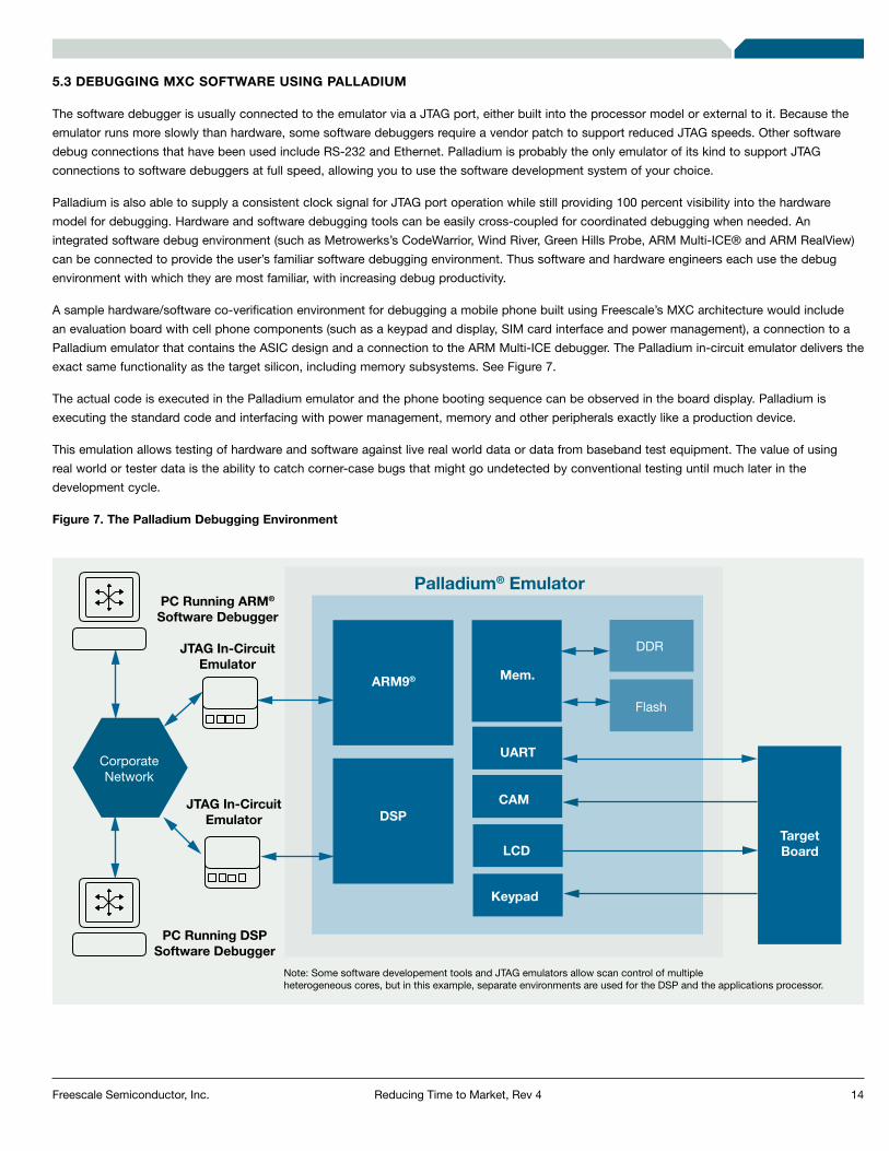
A sample hardware/software co-verification environment for debugging a mobile phone built using Freescale’s MXC architecture would include an evaluation board with cell phone components (such as a keypad and display, SIM card interface and power management), a connection to a Palladium emulator that contains the ASIC design and a connection to the ARM Multi-ICE debugger. The Palladium in-circuit emulator delivers the exact same functionality as the target silicon, including memory subsystems. See Figure 7.
The actual code is executed in the Palladium emulator and the phone booting sequence can be observed in the board display. Palladium is executing the standard code and interfacing with power management, memory and other peripherals exactly like a production device.
This emulation allows testing of hardware and software against live real world data or data from baseband test equipment. The value of using real world or tester data is the ability to catch corner-case bugs that might go undetected by conventional testing until much later in the development cycle.
Figure 7. The Palladium Debugging Environment
ARM9®
DSP
Mem.
UART
CAM
LCD
Keypad
TargetBoard
SerialsCommunications
DDR
SerialsCommunications
Flash
CorporateNetwork
PC Running DSPSoftware Debugger
PC Running ARM®
Software Debugger
Palladium® Emulator
JTAG In-CircuitEmulator
JTAG In-CircuitEmulator
Note: Some software developement tools and JTAG emulators allow scan control of multiple heterogeneous cores, but in this example, separate environments are used for the DSP and the applications processor.

15Reducing Time to Market, Rev 4Freescale Semiconductor, Inc.
The Palladium emulator integrates with the CodeWarrior Debugger from Metrowerks, which provides support for source, assembly, or mixed source/assembly debugging and fast, flexible run-control capabilities. See Figure 8. Palladium’s technology shines in debug productivity too, delivering 100 percent visibility into the design six times faster than FPGA-based emulators. True interactive performance for debugging allows up to four times as many design turns a day.
Figure 8. Screen Shot of CodeWarrior Debugger
Another big advantage of the Palladium system is that it is turnkey relative to software testing: software developers are not required to know anything about emulation to use it. The results are an advance in productivity in your testing cycle and improved software quality. With Palladium, software engineers have the same debug environment as on a standard development board. Developers can set breakpoints, inspect registers and memory and make dynamic changes while debugging.
Problems involving the hardware/software interface are also easily debugged using CodeWarrior in conjunction with Palladium’s TurboDebug, which provides full visibility into the hardware.

16Reducing Time to Market, Rev 4Freescale Semiconductor, Inc.
Several companies have established remote environments that provide Palladium access across their corporate WANs to developer teams across the globe on a 24/7 basis. Because they are using the same software debug environment—whether with an ISS, emulated model, prototype, or final system—a high level of productivity is maintained.
The Incisive Palladium accelerator/emulator can be shared very effectively in a multi-user environment. In the case of one of Cadence’s customers, the capacity of a single Incisive emulator is shared among eight users for BIOS and driver software development. Each user can operate their portion of the emulator independently in any mode.
Alternately, the entire system capacity can be used when verifying the complete 35-million-gate design. With multiple systems they will be able to support up to 48 simultaneous software developers with a verification and debugging environment with very high performance.
6. ConclusionForging partnerships with industry leaders Cadence, Virtio and Metrowerks, Freescale provides powerful and comprehensive solutions that advance the development of mobile devices, enabling device manufacturers to start building the smartphones of the future based on the MXC architecture today. By using simulation and emulation technologies, OEMs and ODMs can benefit from faster time to market for their products with increased quality.
Combine these benefits with the advantages in size, cost and advanced technology of Freescale’s MXC architecture and the result is a considerable competitive advantage.
7. ResourcesFor more information on technologies referenced in this document, consult the indicated resources:

Home Page:www.freescale.com
Power Architecture Information:www.freescale.com/powerarchitecture
e-mail:[email protected]
USA/Europe or Locations Not Listed:Freescale SemiconductorTechnical Information Center, CH3701300 N. Alma School RoadChandler, Arizona [email protected]
Europe, Middle East and Africa:Freescale Halbleiter Deutschland GmbHTechnical Information CenterSchatzbogen 781829 Muenchen, Germany+44 1296 380 456 (English)+46 8 52200080 (English)+49 89 92103 559 (German)+33 1 69 35 48 48 (French)[email protected]
Japan:Freescale Semiconductor Japan Ltd.HeadquartersARCO Tower 15F1-8-1, Shimo-Meguro, Meguro-ku,Tokyo 153-0064, Japan0120 191014+81 3 5437 [email protected]
Asia/Pacific:Freescale Semiconductor Hong Kong Ltd.Technical Information Center2 Dai King StreetTai Po Industrial Estate,Tai Po, N.T., Hong Kong+800 2666 [email protected]
For Literature Requests Only:Freescale SemiconductorLiterature Distribution CenterP.O. Box 5405Denver, Colorado 802171-800-441-2447303-675-2140Fax: [email protected]
Information in this document is provided solely to enable system and software implementers to use Freescale Semiconductor products. There are no express or implied copyright license granted hereunder to design or fabricate any integrated circuits or integrated circuits based on the information in this document.
Freescale Semiconductor reserves the right to make changes without further notice to any products herein. Freescale Semiconductor makes no warranty, representation or guarantee regarding the suitability of its products for any particular purpose, nor does Freescale Semiconductor assume any liability arising out of the application or use of any product or circuit, and specifically disclaims any and all liability, including without limitation consequential or incidental damages. “Typical” parameters which may be provided in Freescale Semiconductor data sheets and/or specifications can and do vary in different applications and actual performance may vary over time. All operating parameters, including “Typicals” must be validated for each customer application by customer’s technical experts. Freescale Semiconductor does not convey any license under its patent rights nor the rights of others. Freescale Semiconductor products are not designed, intended, or authorized for use as components in systems intended for surgical implant into the body, or other applications intended to support or sustain life, or for any other application in which the failure of the Freescale Semiconductor product could create a situation where personal injury or death may occur. Should Buyer purchase or use Freescale Semiconductor products for any such unintended or unauthorized application, Buyer shall indemnify and hold Freescale Semiconductor and its officers, employees, subsidiaries, affiliates, and distributors harmless against all claims, costs, damages, and expenses, and reasonable attorney fees arising out of, directly or indirectly, any claim of personal injury or death associated with such unintended or unauthorized use, even if such claim alleges that Freescale Semiconductor was negligent regarding the design or manufacture of the part.
How to Reach Us:
Learn More: For current information about Freescale products and documentation, please visit www.freescale.com.
Freescale and the Freescale logo are trademarks or registered trademarks of Freescale Semiconductor, Inc. in the U.S. and other countries. All other product or service names are the property of their respective owners. ARM is the registered trademark of ARM Limited. ARM9, ARM11, and ARML210™ are the trademarks of ARM Limited. Java and all other Java-based marks are trademarks or registered trademarks of Sun Microsystems, Inc. in the U.S. and other countries. © Freescale Semiconductor, Inc. 2008.Document Number: MXCSWDEVWP REV 4