reduction of ber using rsc code for optical code division ... · pdf filereduction of ber...
TRANSCRIPT

Available online at www.worldscientificnews.com
WSN 81(2) (2017) 106-120 EISSN 2392-2192
Reduction of BER using RSC code for Optical Code Division Multiple Access Networks
Satyasen Panda
Department of Electronics Engineering, IGIT, Sarang, India
E-mail address: [email protected]
ABSTRACT
In this study, a two dimensional (2-D) wavelength hopping and time spreading (WHTS) optical
code division multiple access (OCDMA) code is designed using Sparse ruler technique. The proposed
64 bit 2-D code is constructed by an algorithm based on random spacing of sparse codes referred in
this work as Random Sparse Code (RSC). The performance of the proposed 2-D RSC is evaluated in
terms of bit error rate (BER), received signal power and time domain analysis of received signals. The
system performance of the OCDMA system utilizing 2-D RSC code improved significantly due to less
BER, low cross correlation property and simple encoder/decoder design. The output BER is much
lower at a data rate of 1.25 gbps and 2.5 gbps for a distance of 100 km with ITU-T standard single
mode fiber with attenuation level of 0.2dB/km.
Keyword: Cross Correlation (CC), Optical Code Division Multiple Access (OCDMA), Multiple
Access Interface (MAI), Random Sparse Code (RSC), Wavelength hopping time spreading (WHTS)
1. INTRODUCTION
The Optical code division multiple access (OCDMA) is an advanced form of
multiplexing technology for the latest optical networks which created a lot of attention due to
its various features including better network flexibility, protocol transparency, asynchronous
operation and enhanced security for allowing dynamic resource sharing between multiple
users in an effective way. But the crucial issue in OCDMA system is to find a coding system
that can nullify the effects of co-channel interference, multiple access interference (MAI) and
World Scientific News 81(2) (2017) 106-120
-107-
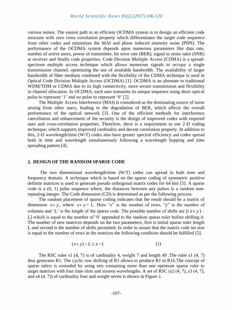
various noises. The easiest path to an efficient OCDMA system is to design an efficient code
structure with zero cross correlation property which differentiates the target code sequence
from other codes and minimizes the MAI and phase induced intensity noise (PIIN). The
performance of the OCDMA system depends upon numerous parameters like data rate,
number of active users, power of transmitter, bit error rate (BER), signal to noise ratio (SNR)
at receiver and finally code properties. Code Division Multiple Access (CDMA) is a spread-
spectrum multiple access technique which allows numerous signals to occupy a single
transmission channel, optimizing the use of available bandwidth. The availability of larger
bandwidth of fiber medium combined with the flexibility of the CDMA technique is used in
Optical Code Division Multiple Access (OCDMA) [1]. OCDMA is an alternate to traditional
WDM/TDM or CDMA due to its high connectivity, more secure transmission and flexibility
in channel allocation. In OCDMA, each user transmits its unique sequence using short optical
pulse to represent ‘1’ and no pulse to represent ‘0’ [2].
The Multiple Access Interference (MAI) is considered as the dominating source of noise
arising from other users, leading to the degradation of BER, which affects the overall
performance of the optical network [3]. One of the efficient methods for interference
cancellation and enhancement of the security is the design of improved codes with required
auto and cross-correlation properties. Therefore, there is a requirement to use 2-D coding
technique, which supports improved cardinality and decent correlation property. In addition to
this, 2-D wavelength/time (W/T) codes also have greater spectral efficiency and codes spread
both in time and wavelength simultaneously following a wavelength hopping and time
spreading pattern [4].
2. DESIGN OF THE RANDOM SPARSE CODE
The two dimensional wavelength/time (W/T) codes can spread in both time and
frequency domain. A technique which is based on the sparse coding of symmetric positive
definite matrices is used to generate pseudo orthogonal matrix codes for 64 bits [5]. A sparse
code is a (0, 1) pulse sequence where, the distances between any pulses is a random non-
repeating integer. The Code dimension (CD) is determined as per the following process. The random placement of sparse coding indicates that the result should be a matrix of
dimension x y , where x y > L. Here “x” is the number of rows, “y” is the number of
columns and ‘L’ is the length of the sparse code. The possible number of shifts are [( x y ) –
L] which is equal to the number of ‘0’ appended to the random sparse ruler before shifting it. The number of new matrices depends on the two parameters, first is initial sparse ruler length L and second is the number of shifts permitted. In order to assure that the matrix code set size is equal to the number of rows in the matrices the following condition should be fulfilled [5].
( ) 1x y L x (1)
The RSC ruler s1 (4, 7) is of cardinality 4, weight 7 and length 49 .The ruler s1 (4, 7)
thus generates R1. The cyclic row shifting of R1 allows to produce R1 to R16.The concept of sparse rulers is extended by using sets containing more than one optimum sparse ruler to target matrices with four time slots and sixteen wavelengths. A set of RSC (s2 (4, 7), s3 (4, 7), and s4 (4, 7)) of cardinality four and weight seven is shown in Figure 1.

World Scientific News 81(2) (2017) 106-120
-108-
Fig. 1. Construction of s1 (4, 7) to s4 (4, 7) RSC
Similarly, the cyclic row shifting of s2 (4, 7) generates R17 to R32, s3 (4, 7) generates R33 to R48 and s4 (4,7) generates R49 to R64. The RSC code is generated using the algorithm, which satisfies the following two conditions:
1. The distance between any pulses is non-repeating integer.
2. ( ) 1x y L x where, “x” is the number of rows, “y” is the number of columns and
L is the length of the sparse ruler. In this work, eight wavelengths are reused in place
of sixteen wavelengths.
Algorithm to generate N bit codes
Let, L be the code length before zero truncation & W be the code weight. A
predefined set is defined which will contain zeroes sequences (0, 00, …………,
0000,…, L-W zeroes). The proposed RSC has a code length of 49 before zero
truncation and has a code weight of 7. Therefore, the predefined set will be as shown
here.
Predefinedset = ( 0, 00, …………, 0000, …, 42 zeroes)
Then, W+1 zero sequences will be chosen randomly from the set. Let y1, y2,
y3…………yN be the randomly chosen sequences, for example y1 = 00000, y2 = 000
and so on [6].
Now, the comparison between all the sequences is made to check if they are equal. If
any two or more of them are equal the previous step is repeated.
Again, the W+1 zero sequences are concatenated by putting 1 between every two
zeroes sequences. In the proposed RSC, the number of one’s equal to the weight of the
code. Hence, number of ones to be placed in the code equals to seven and is placed in
between sequences such as y1, y2 and so on. Therefore, the final code R before zero
truncation is represented as below with a code length L = 49.
R = y1 + 1+ y2 + 1 + y3 +1 + y4 …….
Then, extra zeroes are added to the sparse rulers to get the RSC. For example, fifteen
zeroes are added to a 49 bit code length (R) to get a 64 bit RSC. The construction of
R1 and R2 is presented in table 1 and table 2 respectively.

World Scientific News 81(2) (2017) 106-120
-109-
Each generated sparse ruler is shifted x-1 times to generate r more codes. In this work,
x is taken as 16.
Hence, they are arranged in form of a matrix with x rows and y columns. In this work,
y is taken as 4.
Table 1. Construction of R1 using sparse ruler
Table 2. Construction of R2 using sparse ruler
x/y y1 y2 y3 y4
x1 0 0 0 0
x2 0 0 0 0
x3 0 0 0 0
x4 0 0 1 0
x5 0 1 0 0
x6 0 0 0 0
x7 0 1 0 0
x8 0 1 0 0
x9 0 0 0 0
x10 0 0 0 0
x11 0 0 0 0
x12 0 0 0 0
x13 0 0 0 0
x14 0 0 0 0
x15 0 1 0 0
x16 1 1 0 0
x/y y1 y2 y3 y4
x1 0 1 1 0
x2 0 0 0 0
x3 0 0 0 0
x4 0 0 0 0

World Scientific News 81(2) (2017) 106-120
-110-
Similarly, for the rest of the users, the Pseudo orthogonal (PO) matrices are converted to wavelength/time (W/T) sparse codes by associating the rows of the PO matrices with wavelength (or frequency) and the columns with time-slots, as shown below in Table 3.
Table 3. The PO matrix codes using sparse ruler
The matrices R1….. R16 are numbered 1…. 16 in the table, with the corresponding
assignment of wavelengths and time-slots. The code R3 is shown bold in table. The code R3
x5 0 0 1 0
x6 0 1 0 0
x7 0 0 0 0
x8 0 1 0 0
x9 0 1 0 0
x10 0 0 0 0
x11 0 0 0 0
x12 0 0 0 0
x13 0 0 0 0
x14 0 0 0 0
x15 0 0 0 0
x16 0 1 0 0
Wavelength
(W)
Time slots
1 2 3 4
1 2, 2,10,5,4,3 2,13,12,11,3, 11,10,6 14
2 3, 11,6,5,4 14,13,12,4,3, 12,11,7 15
3 4, 12,7,6,5 15,14,13,5,4, 13,12,8 16
4 5, 13,8,7,6 1,16,15,14,6,5, 14,13,9
5 1,6, 14,9,8,7 2,16,15,7,6, 15,14,10
6 2,7, 15,10,9,8 16,8,7,3, 16,15,11
7 1,8,3,1,16,11,10,9 9,8,4, 16,12
8 1 1,2,9,4,3,1,2,12,11,10 10,9,5, 13

World Scientific News 81(2) (2017) 106-120
-111-
is represented as (0; λ1, λ2, λ7, λ8; λ1, λ2, λ6; 0) similar to the work in [6]. In this work, the
semicolons separate the time-slots in the code.
3. BLOCK DIAGRAM AND SIMULATION CIRCUIT DIAGRAM
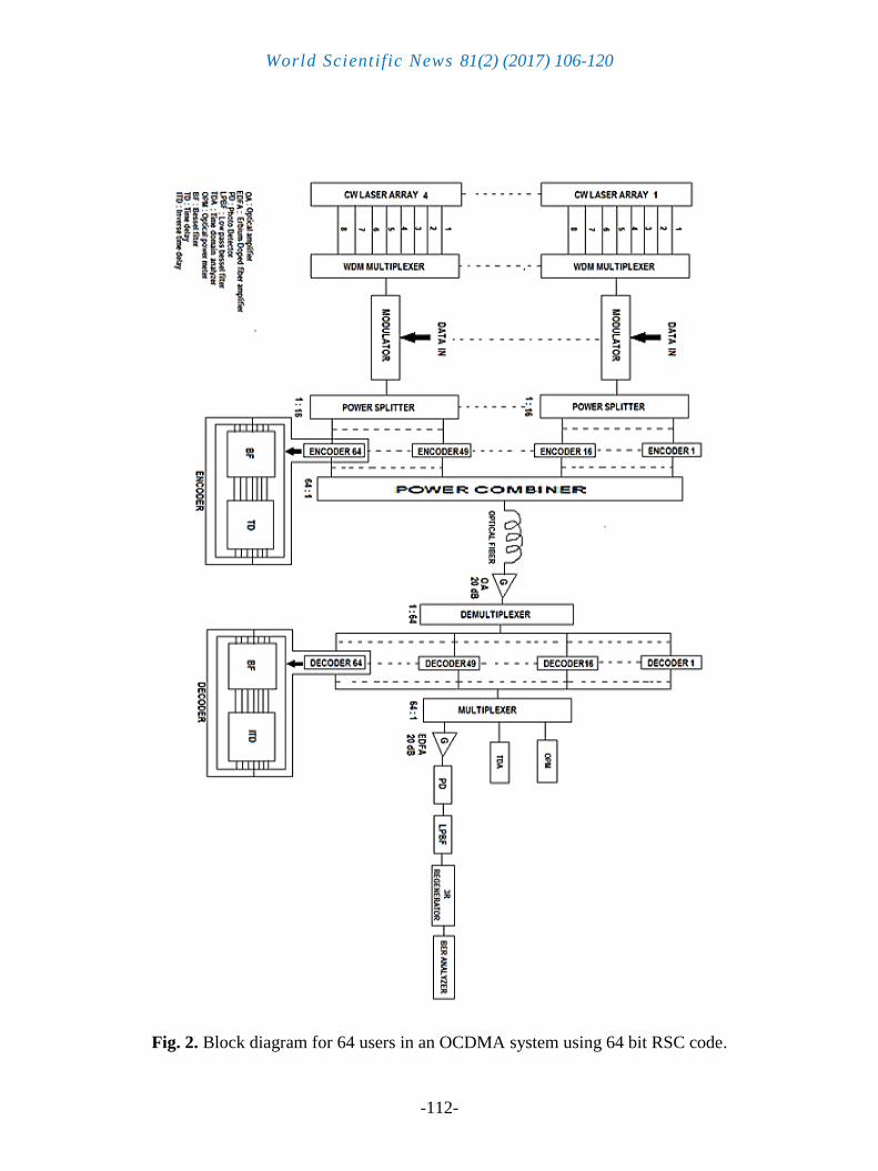
In this work, the proposed RSC code is designed for 64 users. The block diagram of the
OCDMA trans-receiver for the proposed code is as shown in Figure 2. In this work, eight CW
lasers (wavelength 1 to 8) are used to create a multicarrier signal to modulate the user data.
The wavelengths range from 193.1 nm to 193.8 nm, with 0.1 nm wavelength spacing. The
generated multicarrier is used to modulate the pseudo-random bit sequence data of user. The
data rate used in the system varies from 1.25 Gbps to 2.5 Gbps. The RZ pulse generator is
used to encode the data. A Mach-Zehnder modulator, which is an external modulator, is used
to modulate the data. After modulation, the modulated data is fed to the 1: 16 power splitter,
which splits the modulated optical signal to the respective encoders for wavelength hopping
and time spreading encoding. In an encoder, one optical Bessel filter and one time delay
circuit are used to produce an encoded wavelength/time (W/T) bit stream. Each group of light
source has sixteen numbers of encoders and therefore, four groups of light sources have a
total of 64 encoders.
Table 4. Simulation parameters used for the proposed 2-D RSC OCDMA system.
Parameter Value
Bit rate (Data rate) 1.25 Gbps -2.5 Gbps
Number of optical sources 8 CW lasers
Wavelength range 193.1–193.8 nm
Wavelength spacing 0.1 nm
Input power 0 dBm
Modulation type RZ Modulation
Codes used RSC Codes
Code weight 7
Code Length 64
Fibre length 100 km
Attenuation 0.2 dB/km
World Scientific News 81(2) (2017) 106-120
-112-
Fig. 2. Block diagram for 64 users in an OCDMA system using 64 bit RSC code.
World Scientific News 81(2) (2017) 106-120
-113-
Fig. 3. The OCDMA system circuit for two users implementing RSC codes

World Scientific News 81(2) (2017) 106-120
-114-
All the encoded data is then combined using four 16:1 power combiner and sent over a
single mode optical fiber. The encoded data from all the users are combined by power
combiners and then passed through a 100 km single mode optical fiber followed by a loss
compensating optical amplifier with gain of 20 dB and noise figure of 4 dB. The output signal
from the fiber is then passed through an Ideal demultiplexer followed by the user’s decoders.
For simplification of the block diagram in this work, the received optical bit stream is given to
1: 64 demultiplexer followed by the 64 decoders. In a decoder, one optical Bessel filter and
one inverse time delay are used to decode the bit sequences. All the decoded signals are
multiplexed using 64: 1 multiplexer and output is fed to an optical time domain analyzer, an
optical power meter and a photo detector. Optical power meter is used for optical power
measurement. Photo detector detects and converts the information into electrical form
followed by Erbium-doped fiber amplifier (EDFA) followed by a 3-R Regenerator that is used
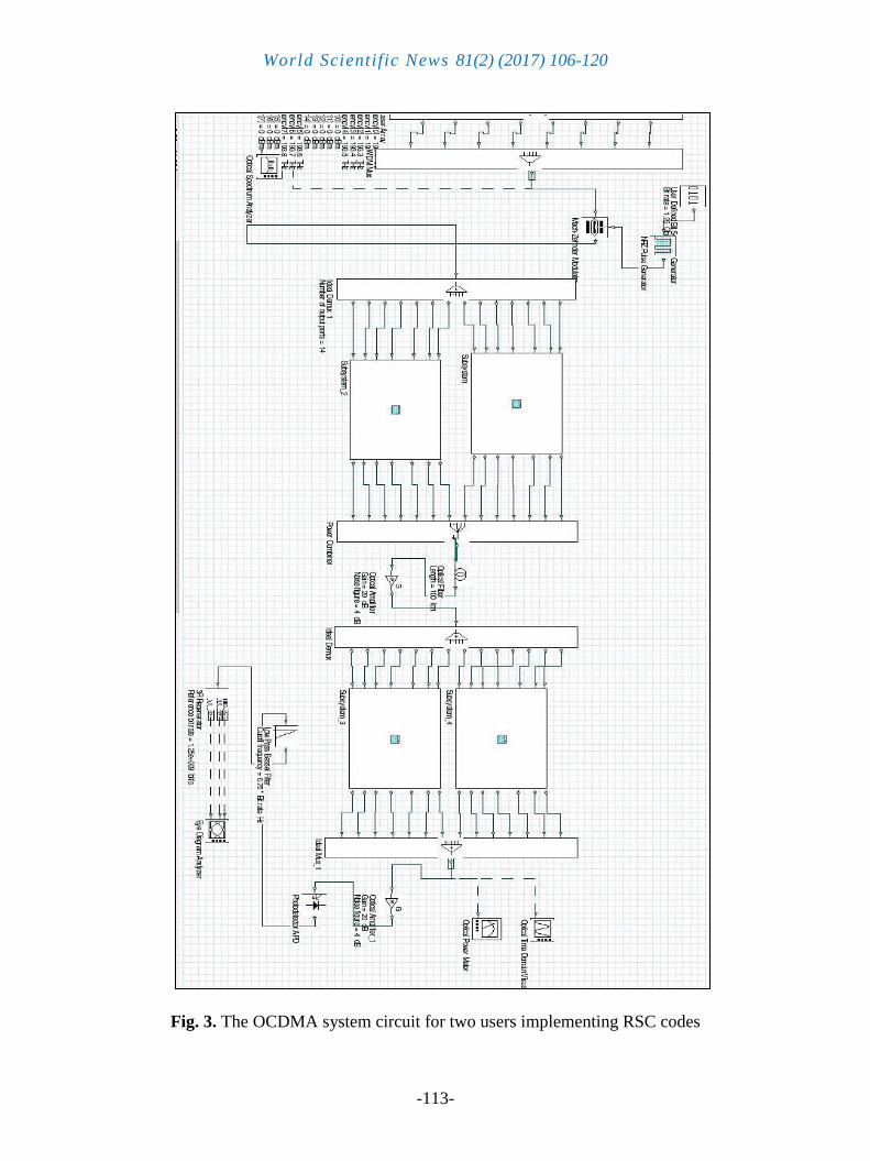
to re-amplify, re-shape and re-time the electrical signal. The optical CDMA network using
RSC code for two users at a data rate of 2.5 Gbps, is implemented using Optisystem version
14 as shown in Figure 3.
4. RESULTS AND DISCUSSIONS
Using simulation parameters as mentioned in the Table 4, the bit error rate (BER), and
optical power of the received signals are measured for different number of active users. BER
is measured at the receiver end by using the Eye Diagram Analyser. With the help of the
optical power meter, received power is measured at the receiver side.
Fig. 4. BER vs. Fiber length at 1.25Gbps and 2.5 Gbps for RSC code
20 30 40 50 60 70 80 90 100 110 120-200
-180
-160
-140
-120
-100
-80
-60
-40
-20
0
FIBER LENGTH
BE
R
1.25 Gbps
2.5 Gbps
DATA RATE

World Scientific News 81(2) (2017) 106-120
-115-
Figure 4 shows the graph between BER versus fiber length using the proposed 64 bit
RSC codes for various data rates for eight numbers of active users. It is seen that for different
fiber lengths BER is lower at 1.25 Gbps data rate than at higher data rate such as 2.5 Gbps.
Hence, it can be inferred that BER can be reduced by decreasing the data rate for the proposed
RSC code leading to better system performance. At higher data rate, the fiber linear
impairments such as polarized mode dispersion and nonlinear impairment including the fiber
attenuation degrade the system performance. Therefore, the proposed RSC has better
performance at lower data rates when compared to its performance at high data rates.
However, the difference is not much and hence, the proposed code can be used up to a fiber
length of 100 km at a data rate of 2.5 Gbps, which gives the BER value less than 10-9
, which
is acceptable for communication purpose.
Figure 5 shows the variation of received power over fiber length for various fiber
attenuation of the proposed RSC. It is seen that with increase in attenuation the received
power decreases. However, the received power is much higher compared to the results
obtained for identical fiber length and fiber attenuation. This experiment proves that the
proposed RSC has better performance in terms of the received power.
Fig. 5. Received power vs. fiber length at different attenuation values
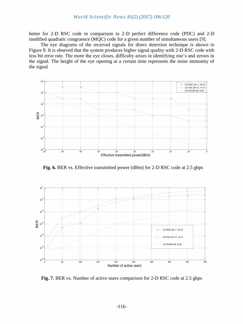
The BER variation against effective transmitted power (dBm) for various types of 2-D codes is shown in Figure 6. It is observed that the proposed 2-D RSC code requires lowest optical transmission power compared to other codes like 2-D MQC [7] and 2-D PDC [8] codes because of effective suppression of PIIN noise which improves the overall system performance.
The BER variation against number of simultaneous users for different types of 2-D codes at 2.5 gbps is demonstrated in Figure 7. It is observed that BER performance is much
20 30 40 50 60 70 80 90 100 110 120-20
-15
-10
-5
0
5
10
15
FIBER LENGTH
RE
CE
IV
ED
P
OW
ER
1 dBm
2 dBm
3 dBm
ATTENUATION
World Scientific News 81(2) (2017) 106-120
-116-
better for 2-D RSC code in comparison to 2-D perfect difference code (PDC) and 2-D modified quadratic congruence (MQC) code for a given number of simultaneous users [9].
The eye diagrams of the received signals for direct detection technique is shown in Figure 8. It is obseved that the system produces higher signal quality with 2-D RSC code with less bit error rate. The more the eye closes, difficulty arises in identifying one’s and zeroes in the signal. The height of the eye opening at a certain time represents the noise immunity of the signal
Fig. 6. BER vs. Effective transmitted power (dBm) for 2-D RSC code at 2.5 gbps
Fig. 7. BER vs. Number of active users comparison for 2-D RSC code at 2.5 gbps
-50 -45 -40 -35 -30 -25 -20 -15 -10 -510
-8
10-6
10-4
10-2
100
102
104
Effective transmitted power(dBm)
BE
R
2-D MQC (p1=7, p2=3)
2-D PDC (M=73 , N=7)
2-D RSC(M=80, N=9)
0 50 100 150 200 250 300 350 400 45010
-60
10-50
10-40
10-30
10-20
10-10
100
Number of active users
BE
R
2-D MQC (p1=7, p2=3)
2-D PDC (M=73 , N=7)
2-D RSC(M=80, N=9)

World Scientific News 81(2) (2017) 106-120
-117-
Fig. 8. Eye diagram using RSC codes in case of 2.5 Gbps data rate, 10 users,
W = 7 and 100 km link length
The performance of the time domain signal for eight users with 2-D RSC code for
various delays of 2ns, 4ns and 6ns at the encoder at a data rate of 2.5 Gbps for 100 km fiber span is shown in Figure 9 (a), (b), (c) respectively. It is observed from the time domain analysis that for the proposed RSC, the signal power levels remain almost identical at 2.5 Gbps data rate for various delay factors. This implies that there is no degradation of signal power level for a fixed number of users and fiber distance for different delays.

World Scientific News 81(2) (2017) 106-120
-118-
Fig. 9. (a) 8 users power level with delay of 2 ns (b) 8 users power level with delay of 4 ns (c)
8 users power level with delay of 6 ns at data rate of 2.5 gbps with RSC code for 100 km
fiber span

World Scientific News 81(2) (2017) 106-120
-119-
5. CONCLUSION
In this paper, a new class of optical codes based on sparse ruler is presented. For
analyzing the performance of OCDMA system, the received power and bit error rate for RSC code are measured. The simulation results show improved performance of designed OCDMA system. The simulated Optical CDMA system for proposed work has resulted in better performance in terms of BER for fiber span of 100 kilometer at a data rate of 2.5 Gbps. The BER can be further lowered by reducing the data rate. The excellent performance of RSC codes in terms of BER is obvious from the comparative analysis with the existing MQC Codes and PDC codes. The RSC code generation algorithm also shows optimum performance as evident from BER analysis, time delay analysis and eye diagram. Hence, the proposed code is suitable for local area networks or even for long haul network up to 100 km fiber length at data rate of 2.5 Gbps.
ACKNOWLEDGEMENT
The author would like to extend his sincere appreciation to the All India Council of Technical Education (AICTE) for the funding of this research through the research project number 20/AICTE/RIFD/RPS (POLICY-II) 2/2012-13
References
[1] Zouine Y, Dayoub I, Haxha S, Rouvaen J. M., Analyses of constraints on high speed
optical code division multiplexing access (OCDMA) link parameters due to fiber optic
chromatic dispersion. Journal of Optical Communication, 281 (2008) 1030-1036
[2] S.Yegnanarayanan, A.S. Bhushan, B. Jalali, Fast wavelength-hopping time spreading
encoding/decoding for optical CDMA. IEEE Photonic Technol. Letters 12 (2000) 166-
177
[3] Satyasen Panda, Effect of SHIFTZCC codes for optical CDMA system. World Scientific
News 67 (2017) 365-389
[4] Satyasen Panda, Two dimensional optical CDMA network with incoherent detection
technique. Imperial journal of interdisciplinary research, 3 (2017) 818-827
[5] M. Elad, Sparse and Redundant Representations: From Theory to Applications in Signal
and Image Processing, Springer, 2010.
[6] M. Aharon, M. Elad, and A. Bruckstein, K-SVD: An algorithm for designing over
complete dictionaries for sparse representation. IEEE Transactions on Signal
Processing 54 (2006) 4311-4322
[7] Zou Wei, H. M. H. Shalaby, H. Ghafouri-shiraz. Modified quadratic congruence code
for fiber Bragg Grating based spectral amplitude coding optical cdma system. Journal
of light wave technology 19 (2001) 1274-1281

World Scientific News 81(2) (2017) 106-120
-120-
[8] J. H. Wen, J. S. Jhou, C. P. Li. Optical spectral amplitude coding cdma systems using
perfect difference code and interference estimation. IEEE proceedings Optoelectronics,
153 (2006) 152-160
[9] Satyasen Panda, Three dimensional optical CDMA framework with direct detection
technique. World Scientific News 77 (2017) 337-353
( Received 08 July 2017; accepted 21 July 2017 )