reduction of coreduction of co2 emissions fromemissions
TRANSCRIPT

CLEAN COAL DAY IN JAPAN 2010 ( 8th Sep., 2010, ANA InterContinetal Tokyo)
Reduction of CO2 Emissions fromReduction of CO2 Emissions from Coal-fired Power Generation
Masaharu Fujitomi
Executive Managing DirectorExecutive Managing Director
J-POWER
( Electric Power Development Co., Ltd. )

Coal Power Plays a Major Role in Japan
Share of Coal-Fired Power GenerationEnergy Sources for Electricity Generation in Japan Share of Coal Fired Power Generation
Capacity in Japan
2% 2% 2% 2% 2%100%
Generated energy [billion kWh] 379 485 738 940 988
in Japan
Total:38GW3%
17% 27% 34%26%
17% 17% 12% 10% 8%2% 2% 2% 2% 2%
80%
100%
Others
28%71% 44% 27%
10%
10%
40%
60% HydroNuclearOilLNG
18%25%
2%15%
22%
26%28%
20%
LNGCoal
Coal5% 5% 10%
18%2%0%
1973 1980 1990 2000 2008
Coal
(year)

To Curb CO2 Emissions from Coal-fired Power Generation
Possible reduction rate of CO2 per Unit
Coal-Biomass dual firing ▲ 1~10%
red
100%
▲10~30%High Efficiency Power Generation
m C
oal-f
irer
atio
n
▲80~90%
ons
from
wer
Gen
e CO2 Capture & Storage
Emis
sio
Pow
2010 2020 2030 2040 2050
CO
2
( )2010 2020 2030 2040 2050 (year)

Coal-Biomass dual firing
Coal-Biomass dual firing can reduce CO2 emissions from coal-fired power plant without large retrofit.
Bi d l fi i d t bl bi t ( tit d i ) Biomass dual firing needs a stable biomass procurement ( quantity and price ).
G b
FuelizingCoal-fired power
plantCarbonizedGarbage Carbonized
Fuel
Sewage sludge, etc. Coal
Biosolid Fuel
Waste wood, etc.
Wood Biomass
Fuel

Improving Efficiency of Coal-fired Power by JPOWER
(1,050MW×2units)
n
HH
V)
(700MW) (156MW×2units)
(1,000MW)
(1,000MW)
(600MW) (600MW)
ffici
ency
on
, bas
ed o
n
(250MW×2units) (500MW×2units)
700MW (1983)
1,000MW (1990)
1,050MW (2000)
Ther
mal
eff
nt o
f gen
erat
i
(250MW)500MW (1981)
(1983)
Change in unit capacity of coal-fired power stations(%, a
t poi
n

New Isogo No 1 Startup: 2002
Efficiency Upgrade by Plant Replacement (Isogo Thermal Power Station)
Old Isogo, Startup:1967 New Isogo No.1, Startup: 2002 New Isogo No.2, Startup: 2009
Three P rposes Output 530MW 1,200MW
Three Purposes
◇◇ Output Output UpgradeUpgrade
(265MW×2) (600MW×2)
SOx 60 ppm 20 / 10 ppmNOx 159 ppm 20 / 13 ppmD t 50 / 3N 10 / 5 / 3N
No.1 / No. 2
◇◇ Environmental Environmental UpgradeUpgrade
◇◇ Efficiency Efficiency
Dust 50 mg/m3N 10 / 5 mg/m3N Steam condition Sub-critical Ultra Super Critical(USC)
Efficiency 38% (Gross%; HHV) 42~43% (Gross%; HHV)yyUpgradeUpgrade CO2 Emissions 100 83 ※
※ A comparison of the CO2 emission per gross output (kWh) with an old plant (100 basis).

Estimated CO2 Reduction Potential by Applying the Best Practice of Coal-fired Power Plant in JapanApprox. 1.3 billion tons (Almost equivalent to total CO2 emission from Japan)
Practice of Coal fired Power Plant in Japan
2000
Mt-CO2▲377 (M t)
1500
2000
(▲377) (▲705)+▲705 (M t)+▲180 (M t)
▲1.3 B t (Approx.)
500
1000
(▲180)
0
500
Actual
(▲22)
Estimated Actual Actual ActualEstimated Estimated EstimatedActual
Japan US China India
Estimated Actual Actual ActualEstimated Estimated Estimated
Source : IEA World Energy Outlook 2007, Ecofys International Comparison of Fossil Power Efficiency and CO2 Intensity 2008

Towards Higher Thermal EfficiencyDevelopment of Coal-fired Power Generation Pulverized Coal-Fired System (PCF): Efficiency upgrade by increasing steam temperature and
pressure; A-USC (Advanced USC, 700℃ class) is under development I t t d C l G ifi ti C bi d C l S t (IGCC) C bi d G t bi (GT) d
Development of Coal fired Power Generation
Integrated Coal Gasification Combined Cycle System (IGCC): Combined Gas turbine (GT) and steam turbine (ST) cycle; Higher thermal efficiency than PCF; Increasing the GT inlet gas temperature is necessary for efficiency upgrade
Integrated Coal Gasification Fuel Cell Combined Cycle System (IGFC): Triple combined cycle (GT+ST+FC); Higher thermal efficiency than IGCC
① PCF ② IGCC(1500℃ class) ③ IGFC
Latest PCF (USC)
700℃ class (A-USC)
G ifi
GT
STGT
FC
Gasifier STBoiler ST
Gross:42~43%(HHV)Net : 41%(HHV)
Gross:51~53%Net :46~48%
Gross:60%~Net :55%~
Gasifier STBoiler ST
Gross:48%Net : 46%Net : 41%(HHV)
(Basis)Net :46 48%CO2 reduction: approx. 13%
Net :55%CO2 reduction: approx. 25%~
Net : 46%CO2 reduction:
approx. 11%

Overview of CCS Projects by J-POWER
4 Partnership: J-POWER/MHI @J-POWER Matsushima P/SPCF
J-POWER covers three major CO2 Capture technologies from thermal power stations
4 Method: Chemical Absorption (KS-1)
4 Gas flow rate: 1,750Nm3/h
4 CO2 Capture rate: 10 t/dayPost-combustion
PCF
CO2 Capture rate: 10 t/day
4 Test period: July ‘06 – October ‘08
PCF4 Partnership: CS Energy, ACA, Xstrata Coal, Shlumberger /
J-POWER, IHI, Mitsui @ Callide A P/S in QL, Australia
Pilot Plant
Oxyfuel Combustion
PCF J POWER, IHI, Mitsui @ Callide A P/S in QL, Australia4 Fund: Australian Gov. and Japanese Gov.4 Plant Capacity: 30MWe4 CO2 Capture rate: Up to 75t/d2 p p4 Storage: Depleted gas field / Saline Aquifer4 Test period: August ‘11 – Mid ‘14
4 Partnership: J POWER/NEDO @J POWER Wakamatsu Research
Demo. Plant
Pre-Combustion
Coal Gasification4 Partnership: J-POWER/NEDO @J-POWER Wakamatsu Research
Institute, EAGLE plant
4 Method: Chemical Absorption (MDEA)
4 Gas flow rate: 1 000Nm3/hPre Combustion 4 Gas flow rate: 1,000Nm3/h
4 CO2 Capture rate: approx. 20 t/d
4 Test period: Nov. ‘08 – March ‘14Pilot Plant

EAGLE Pilot Plant TestJ POWER Wakamatsu Research Institute
The main purpose of this project is to research physical absorption CO capture technologies for a coal
Innovative CO2 Capture Technology for EAGLEInnovative CO2 Capture Technology for EAGLECoal gasification unitAir separation
unit
J-POWER Wakamatsu Research Institute ( Kitakyushu City, Japan )
absorption CO2 capture technologies for a coal gasification process by using the oxygen-blown coal gasification pilot plant (EAGLE). To have two types of CO2 capture process (i.e. chemical
b ti d h i l b ti ) i th EAGLE il t
Gas clean-up unit
absorption and physical absorption) in the EAGLE pilot plant, and conduct an experimental study with comparing two types of CO2 capture technology.【Partnership】 J-POWER / NEDO【Test Period】 4years (Summer 2010 ‐ March 2014)
CO2 Capture unit Gas turbine unit
(FY)(FY)(FY)(FY)
STEP-2STEP-120092008200720062005200420032002
Ga
Gas
CO
CO
1995~2001
Plan2010 2011 2012 2013
COCO2 2 capturecaptureChemicalChemical
COCO2 2 capturecapturePhysicalPhysical
STEP-2STEP-120092008200720062005200420032002
Ga
Gas
CO
CO
1995~2001
Plan2010 2011 2012 2013
COCO2 2 capturecaptureChemicalChemical
COCO2 2 capturecapturePhysicalPhysical
TrialTrialoperationoperation
Coal Flexibility TestCoal Flexibility Test
Performance TestPerformance Test
sifier Modificatio
sifier Modificatio
OO22
capture systemcapture system
Coal FlexibilityCoal Flexibilitytesttest
DesignDesign
&&
ConstructionConstruction
-- Chemical Chemical Absorption Absorption --
-- Physical Physical Absorption Absorption --
Design, Design, Construction, Construction,
Reliability TestReliability Test
ScaleScale--up Testup Test
Reliability TestReliability Test
ononm installation
m installation
Survey of TraceSurvey of TraceElement behaviorElement behavior
TestTest
Reliability TestReliability Test
ScaleScale--up Testup Test
Reliability TestReliability Test
ononm installation
m installation
Survey of TraceSurvey of TraceElement behaviorElement behavior
TestTest

Osaki CoolGen Project (IGCC demo.)
◎ The Chugoku Electric Power Company and J-POWER agreed to jointlydemonstrate a large-scale oxygen-blown coal gasification technology (IGCC)and CO2 capture technology in Osaki, Hiroshima.
◎ We have jointly established the Osaki CoolGen company in Hiroshima in July,2009, and are executing environmental assessment for the demonstration now.
Plant Output : 170MW ClassCoal Feed Rate : 1,100t/day Class
OptimizationR h d St d
Fiscal Year 2009 2010 2011 2012 2013 2014 2015 2016 2017 2018 2019 2020 2021 20222009 2010 2011 2012 2013 2014 2015 2016 2017 2018 2019 2020 2021 2022
Environmental Impact Assessment
Research and Study
設計・建設 実証試験Design,Manufacturing
d I t ll tiDemonstrationO tiOxygen blown
IGCC
onst
ratio
n
設計 建設 実証試験
実証機
The demonstration operation will be carried out in 2 steps.・1st step:Test operation of 170MW IGCC. (from March, 2017)
and Installation
The start of construction
Modification
Operation
The start of operation
CO2 Capturewith IGCCD
em
実証機改造
設計・建設 実証試験
・2nd step:Test operation of IGCC with CO2 Capture. (from 2021)Modification
Demonstration Operation
Design,Manufacturingand Installation
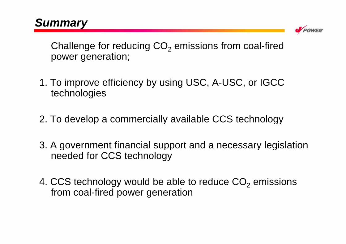
Summary
Challenge for reducing CO2 emissions from coal-fired power generation;
1. To improve efficiency by using USC, A-USC, or IGCC technologiestechnologies
2. To develop a commercially available CCS technology2. To develop a commercially available CCS technology
3. A government financial support and a necessary legislationg pp y gneeded for CCS technology
4. CCS technology would be able to reduce CO2 emissions from coal-fired power generation

Thank you for your attentionThank you for your attention.