redundant line control function guide 4.3 configuration
TRANSCRIPT
J2S2-1592-02ENZ0(05)May 2016
Oracle Solaris
PRIMECLUSTER Global Link Services
Configuration and AdministrationGuide 4.3Redundant Line Control Function
Preface
Purpose
This document describes the installation, configuration, operation, and maintenance of PRIMECLUSTER Global Link Services (hereafterGLS).
Who should use this document
This document is intended for system administrators who are familiar with GLS operations and cluster control. Anyone who installs,configures, and maintains GLS to increase the availability of the system should read this documentation. A basic knowledge ofPRIMECLUSTER is assumed.
Abstract
The document consists of the following chapters, appendices, and glossary:
Chapter 1 Overview
This chapter explains the redundant line control function of GLS.
Chapter 2 Feature description
This chapter outlines the functions and features of GLS.
Chapter 3 Environment configuration
This chapter discusses how to set up and configure GLS.
Chapter 4 Operation
This chapter explains how to operate the redundant line control function.
Chapter 5 GLS operation on cluster systems
This chapter explains how to operate the redundant line control on a cluster system.
Chapter 6 Maintenance
This chapter focuses on a general approach to troubleshooting. It presents a troubleshooting strategy and identifies commands that areavailable in Resource Coordinator for finding and correcting problems. Further, it discusses how to collect troubleshooting information.
Chapter 7 Command reference
This chapter outlines GLS commands.
Appendix A Messages and corrective actions
This appendix outlines messages and corrective actions to be taken to eliminate errors.
Appendix B Examples of configuring system environments
This appendix explains how to configure the system environment with redundant network control.
Appendix C Operations in Solaris Zones Environment
This appendix describes the operation of GLS on Solaris Zones.
Appendix D Operation in Oracle VM Environments
This appendix describes the operation of GLS in Oracle VM environments.
Appendix E Changes from previous versions
This appendix discusses changes to the GLS specification. It also suggests some operational guidelines.
Appendix F Notice of supplemental information
This appendix provides supplemental information regarding GLS.
Related documentation
Please refer to the following documents according to need:
- i -

- PRIMECLUSTER Global Link Services Configuration and Administration Guide: Redundant Line Control Function for Virtual NICMode
- PRIMECLUSTER Concepts Guide
- PRIMECLUSTER Installation and Administration Guide
- Enhanced Support Facility User's Guide For Dynamic Reconfiguration
- Enhanced Support Facility User's Guide Dynamic Reconfiguration I/O device
- Fujitsu M10/SPARC M10 Systems Domain Configuration Guide
- Fujitsu M10/SPARC M10 Systems XSCF Reference Manual
- Fujitsu M10-1/SPARC M10-1 Service Manual
- Fujitsu M10-4/Fujitsu M10-4S/SPARC M10-4/SPARC M10-4S Service Manual
- PCI Expansion Unit for Fujitsu M10/SPARC M10 Systems Service Manual
- SPARC Enterprise M4000/M5000/M8000/M9000 Servers Dynamic Reconfiguration (DR) User's Guide
- SPARC Enterprise M3000/M4000/M5000/M8000/M9000 Servers XSCF User's Guide
- SPARC Enterprise M4000/M5000 Servers Service Manual
- SPARC Enterprise M8000/M9000 Servers Service Manual
- OSIV VTAM-G TISP Handbook
- Oracle VM Server for SPARC Guide
Notational convention
The document conforms to the following notational conventions:
Point
Text that requires special attention
Note
Information that users should be cautious of
Information
Information that users can refer to
See
Manuals users find workable
Abbreviated name
- Oracle Solaris might be described as Solaris or Solaris Operating System.
- Oracle Solaris 10 is abbreviated as Solaris 10.
- Oracle Solaris 11 is abbreviated as Solaris 11.
- Oracle VM Server for SPARC is abbreviated as Oracle VM.
- ii -
- Oracle Solaris Zones are abbreviated as Solaris Zones.
Export Controls
Exportation/release of this document may require necessary procedures in accordance with the regulations of your resident countryand/or US export control laws.
Trademark
- UNIX is a registered trademark of The Open Group in the United States and other countries.
- Oracle and Java are registered trademarks of Oracle and/or its affiliates. Other names may be trademarks of their respective owners.
- Ethernet is a trademark of Fuji Xerox Corporation.
- PRIMECLUSTER is a registered trademark of Fujitsu Limited.
- Other product names that appear in this manual are product names, trademarks, or registered trademarks of respective companies.
Date of publication and edition
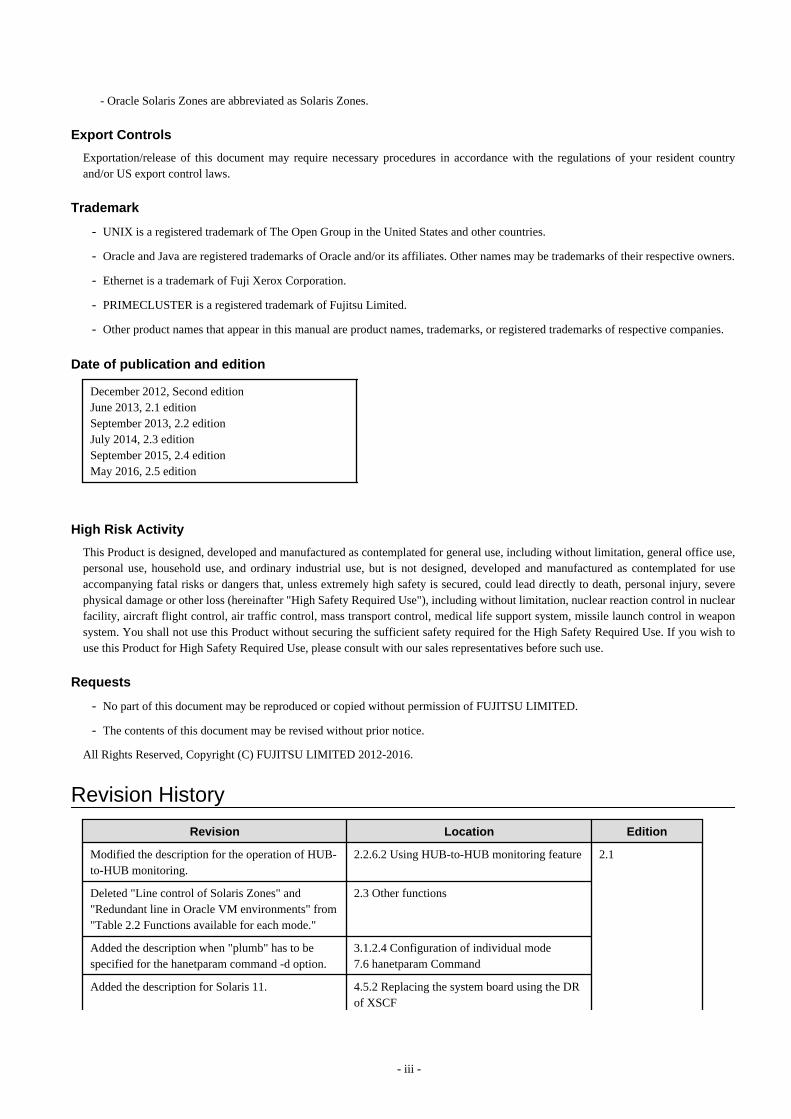
December 2012, Second editionJune 2013, 2.1 editionSeptember 2013, 2.2 editionJuly 2014, 2.3 editionSeptember 2015, 2.4 editionMay 2016, 2.5 edition
High Risk Activity
This Product is designed, developed and manufactured as contemplated for general use, including without limitation, general office use,personal use, household use, and ordinary industrial use, but is not designed, developed and manufactured as contemplated for useaccompanying fatal risks or dangers that, unless extremely high safety is secured, could lead directly to death, personal injury, severephysical damage or other loss (hereinafter "High Safety Required Use"), including without limitation, nuclear reaction control in nuclearfacility, aircraft flight control, air traffic control, mass transport control, medical life support system, missile launch control in weaponsystem. You shall not use this Product without securing the sufficient safety required for the High Safety Required Use. If you wish touse this Product for High Safety Required Use, please consult with our sales representatives before such use.
Requests
- No part of this document may be reproduced or copied without permission of FUJITSU LIMITED.
- The contents of this document may be revised without prior notice.
All Rights Reserved, Copyright (C) FUJITSU LIMITED 2012-2016.
Revision History
Revision Location Edition
Modified the description for the operation of HUB-to-HUB monitoring.
2.2.6.2 Using HUB-to-HUB monitoring feature 2.1
Deleted "Line control of Solaris Zones" and"Redundant line in Oracle VM environments" from"Table 2.2 Functions available for each mode."
2.3 Other functions
Added the description when "plumb" has to bespecified for the hanetparam command -d option.
3.1.2.4 Configuration of individual mode7.6 hanetparam Command
Added the description for Solaris 11. 4.5.2 Replacing the system board using the DRof XSCF
- iii -
Revision Location Edition
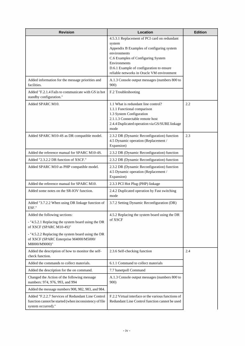
4.5.3.1 Replacement of PCI card on redundantsystemAppendix B Examples of configuring systemenvironmentsC.6 Examples of Configuring SystemEnvironmentsD.6.1 Example of configuration to ensurereliable networks in Oracle VM environment
Added information for the message priorities andfacilities.
A.1.3 Console output messages (numbers 800 to900)
Added "F.2.1.4 Fails to communicate with GS in hotstandby configuration."
F.2 Troubleshooting
Added SPARC M10. 1.1 What is redundant line control?1.1.1 Functional comparison1.3 System Configuration2.1.1.3 Connectable remote host2.4.4 Duplicated operation via GS/SURE linkagemode
2.2
Added SPARC M10-4S as DR compatible model. 2.3.2 DR (Dynamic Reconfiguration) function4.5 Dynamic operation (Replacement /Expansion)
2.3
Added the reference manual for SPARC M10-4S. 2.3.2 DR (Dynamic Reconfiguration) function
Added "2.3.2.2 DR function of XSCF." 2.3.2 DR (Dynamic Reconfiguration) function
Added SPARC M10 as PHP compatible model. 2.3.2 DR (Dynamic Reconfiguration) function4.5 Dynamic operation (Replacement /Expansion)
Added the reference manual for SPARC M10. 2.3.3 PCI Hot Plug (PHP) linkage
Added some notes on the SR-IOV function. 2.4.2 Duplicated operation by Fast switchingmode
Added "3.7.2.2 When using DR linkage function ofESF."
3.7.2 Setting Dynamic Reconfiguration (DR)
Added the following sections:
- "4.5.2.1 Replacing the system board using the DRof XSCF (SPARC M10-4S)"
- "4.5.2.2 Replacing the system board using the DRof XSCF (SPARC Enterprise M4000/M5000/M8000/M9000)"
4.5.2 Replacing the system board using the DRof XSCF
Added the description of how to monitor the self-check function.
2.3.6 Self-checking function 2.4
Added the commands to collect materials. 6.1.1 Command to collect materials
Added the description for the on command. 7.7 hanetpoll Command
Changed the Action of the following messagenumbers: 974, 976, 993, and 994
A.1.3 Console output messages (numbers 800 to900)
Added the message numbers 908, 982, 983, and 984.
Added "F.2.2.7 Services of Redundant Line Controlfunction cannot be started (when inconsistency of filesystem occurred)."
F.2.2 Virtual interface or the various functions ofRedundant Line Control function cannot be used
- iv -

Revision Location Edition
Changed the title name. F.2.2.6 Services of Redundant Line Controlfunction cannot be started (when NIC failed)
Added the notes. 2.4.1 General 2.5
Added the notes. 3.6.6.3 Transfer route error detection time forNIC switching mode3.6.10 Setting User command execution function
Deleted the note about the NIC switching mode. 7.2 strhanet Command
Change the action of the message number 169. A.1.2 Error output message (numbers 100 to 700)
Added the message number 840. A.1.3 Console output messages (numbers 800 to900)
Added the examples of configuration settings inOVM 3.2 environment.
Appendix D Operation in Oracle VMEnvironments
- v -
ContentsChapter 1 Overview..................................................................................................................................................................1
1.1 What is redundant line control?........................................................................................................................................................... 11.1.1 Functional comparison..................................................................................................................................................................41.1.2 Criteria for selecting redundant line control methods.................................................................................................................. 7
1.2 Redundant line control effects............................................................................................................................................................. 71.3 System Configuration.......................................................................................................................................................................... 8
Chapter 2 Feature description................................................................................................................................................122.1 Overview of Functions.......................................................................................................................................................................12
2.1.1 Fast switching mode................................................................................................................................................................... 122.1.1.1 Fault monitoring function.................................................................................................................................................... 132.1.1.2 Switching function...............................................................................................................................................................142.1.1.3 Connectable remote host......................................................................................................................................................152.1.1.4 Available application........................................................................................................................................................... 162.1.1.5 Notes.................................................................................................................................................................................... 16
2.1.2 NIC switching mode................................................................................................................................................................... 162.1.2.1 Fault monitoring function.................................................................................................................................................... 182.1.2.2 Switching function...............................................................................................................................................................192.1.2.3 Connectable remote host......................................................................................................................................................202.1.2.4 Available application........................................................................................................................................................... 202.1.2.5 Notes.................................................................................................................................................................................... 21
2.1.3 GS/SURE linkage mode............................................................................................................................................................. 212.1.3.1 Fault monitoring function.................................................................................................................................................... 242.1.3.2 Switching function...............................................................................................................................................................252.1.3.3 Connectable remote host......................................................................................................................................................252.1.3.4 Available applications..........................................................................................................................................................252.1.3.5 Notes.................................................................................................................................................................................... 25
2.2 Option Functions................................................................................................................................................................................262.2.1 Configuring multiple virtual interfaces.......................................................................................................................................262.2.2 Cluster fail-over when entire transfer routes fails...................................................................................................................... 272.2.3 Sharing physical interface...........................................................................................................................................................28
2.2.3.1 Using Fast switching mode..................................................................................................................................................282.2.3.2 Using NIC switching mode..................................................................................................................................................292.2.3.3 Using GS/SURE linkage mode............................................................................................................................................292.2.3.4 Notices................................................................................................................................................................................. 30
2.2.4 Configuring multiple logical virtual interfaces...........................................................................................................................302.2.5 Configuring single physical interface......................................................................................................................................... 302.2.6 HUB monitoring function...........................................................................................................................................................31
2.2.6.1 Not using HUB-to-HUB monitoring feature....................................................................................................................... 322.2.6.2 Using HUB-to-HUB monitoring feature............................................................................................................................. 332.2.6.3 Transfer path monitoring on individual virtual interface.....................................................................................................35
2.2.7 Monitoring communicating host.................................................................................................................................................382.2.8 Standby patrol function...............................................................................................................................................................382.2.9 Automatic fail-back function...................................................................................................................................................... 392.2.10 Dynamically adding/deleting/switching physical interface......................................................................................................422.2.11 User command execution function........................................................................................................................................... 44
2.3 Other functions.................................................................................................................................................................................. 502.3.1 Message output when a line failure occurs.................................................................................................................................502.3.2 DR (Dynamic Reconfiguration) function................................................................................................................................... 50
2.3.2.1 DR (Dynamic Reconfiguration) linkage function............................................................................................................... 512.3.2.2 DR function of XSCF.......................................................................................................................................................... 53
2.3.3 PCI Hot Plug (PHP) linkage....................................................................................................................................................... 552.3.4 Interface status monitoring feature............................................................................................................................................. 552.3.5 Multiplexing transfer route with Tagged VLAN interfaces....................................................................................................... 55
2.3.5.1 Redundant Line Control function using Tagged VLAN interface...................................................................................... 56
- vi -
2.3.6 Self-checking function................................................................................................................................................................592.4 Notes.................................................................................................................................................................................................. 61
2.4.1 General........................................................................................................................................................................................612.4.2 Duplicated operation by Fast switching mode............................................................................................................................622.4.3 Duplicated operation via NIC switching mode...........................................................................................................................632.4.4 Duplicated operation via GS/SURE linkage mode.....................................................................................................................63
Chapter 3 Environment configuration.....................................................................................................................................653.1 Setup.................................................................................................................................................................................................. 65
3.1.1 Selecting mode............................................................................................................................................................................653.1.2 Selecting appropriate contents.................................................................................................................................................... 66
3.1.2.1 Fast switching mode............................................................................................................................................................ 663.1.2.2 NIC switching mode............................................................................................................................................................ 673.1.2.3 GS/SURE linkage mode...................................................................................................................................................... 693.1.2.4 Configuration of individual mode........................................................................................................................................713.1.2.5 Upper limit of configuration................................................................................................................................................ 73
3.2 System Setup......................................................................................................................................................................................743.2.1 Checking system resources.........................................................................................................................................................743.2.2 Network configuration................................................................................................................................................................74
3.2.2.1 Setup common to modes......................................................................................................................................................743.2.2.2 System setup in Fast switching mode.................................................................................................................................. 773.2.2.3 System setup in NIC switching mode..................................................................................................................................783.2.2.4 System setup in GS/SURE linkage mode............................................................................................................................ 79
3.2.3 syslog setup.................................................................................................................................................................................803.3 Additional system setup.....................................................................................................................................................................81
3.3.1 Fast switching mode................................................................................................................................................................... 813.3.2 NIC switching mode................................................................................................................................................................... 823.3.3 GS/SURE linkage mode............................................................................................................................................................. 833.3.4 Setting parameter for individual mode....................................................................................................................................... 83
3.4 Changing system setup...................................................................................................................................................................... 833.4.1 Fast switching mode................................................................................................................................................................... 843.4.2 NIC switching mode................................................................................................................................................................... 843.4.3 GS/SURE linkage mode............................................................................................................................................................. 863.4.4 Note on changing configuration information..............................................................................................................................87
3.5 Deleting configuration information................................................................................................................................................... 873.5.1 Fast switching mode................................................................................................................................................................... 873.5.2 NIC switching mode................................................................................................................................................................... 883.5.3 GS/SURE linkage mode............................................................................................................................................................. 893.5.4 Note on deleting configuration information............................................................................................................................... 90
3.6 Setting Option Function.....................................................................................................................................................................903.6.1 Configuring multiple virtual interfaces.......................................................................................................................................903.6.2 Switching cluster when all the transfer paths fails..................................................................................................................... 903.6.3 Sharing physical interface...........................................................................................................................................................903.6.4 Multiple logical virtual interface definition................................................................................................................................903.6.5 Single physical interface definition............................................................................................................................................ 903.6.6 HUB monitoring function...........................................................................................................................................................90
3.6.6.1 Creating monitoring information......................................................................................................................................... 913.6.6.2 Enabling HUB monitoring function.................................................................................................................................... 913.6.6.3 Transfer route error detection time for NIC switching mode.............................................................................................. 93
3.6.7 Monitoring the remote host.........................................................................................................................................................983.6.7.1 Transfer route error detection time in GS/SURE linkage mode..........................................................................................983.6.7.2 Transfer route recovery detection time in GS/SURE linkage mode....................................................................................99
3.6.8 Standby patrol function.............................................................................................................................................................1003.6.8.1 Setting what to be monitored............................................................................................................................................. 1003.6.8.2 Setting monitoring interval................................................................................................................................................ 1013.6.8.3 Setting error monitoring interval....................................................................................................................................... 101
3.6.9 Setting dynamic addition/deletion/switching function of physical interfaces.......................................................................... 101
- vii -
3.6.9.1 Dynamic addition of physical interfaces........................................................................................................................... 1013.6.9.2 Dynamic deletion of physical interfaces............................................................................................................................1013.6.9.3 Dynamic switching of physical interfaces......................................................................................................................... 101
3.6.10 Setting User command execution function.............................................................................................................................1013.6.10.1 Settings for NIC switching mode.....................................................................................................................................1023.6.10.2 Settings for GS/SURE linkage mode...............................................................................................................................1093.6.10.3 Settings of the service for Redundant Line Control function.......................................................................................... 110
3.7 Configuring other functions.............................................................................................................................................................1123.7.1 Outputting message when transfer paths fails.......................................................................................................................... 1123.7.2 Setting Dynamic Reconfiguration (DR)................................................................................................................................... 112
3.7.2.1 Configure environment...................................................................................................................................................... 1123.7.2.2 When using DR linkage function of ESF.......................................................................................................................... 113
3.7.3 Transfer route multiplexing with Tagged VLAN interface...................................................................................................... 1143.7.3.1 Operating VLAN interface on Fast switching mode......................................................................................................... 1143.7.3.2 Operating VLAN interface on NIC switching mode......................................................................................................... 115
Chapter 4 Operation.............................................................................................................................................................1184.1 Starting and Stopping Redundant Line Control function................................................................................................................ 118
4.1.1 Starting Redundant Line Control function................................................................................................................................1184.1.2 Stopping Redundant Line Control function..............................................................................................................................118
4.2 Activating and Inactivating Virtual Interfaces.................................................................................................................................1184.2.1 Activating virtual interfaces......................................................................................................................................................1194.2.2 Inactivating virtual interfaces................................................................................................................................................... 119
4.3 Displaying Operation Status............................................................................................................................................................ 1194.4 Displaying Monitoring Status..........................................................................................................................................................1194.5 Dynamic operation (Replacement / Expansion).............................................................................................................................. 119
4.5.1 Executing DR command of ESF...............................................................................................................................................1204.5.2 Replacing the system board using the DR of XSCF.................................................................................................................120
4.5.2.1 Replacing the system board using the DR of XSCF (SPARC M10-4S)........................................................................... 1204.5.2.2 Replacing the system board using the DR of XSCF (SPARC Enterprise M4000/M5000/M8000/M9000)..................... 125
4.5.3 Replacement/Expansion PHP (PCI Hot Plug).......................................................................................................................... 1304.5.3.1 Replacement of PCI card on redundant system................................................................................................................. 1304.5.3.2 Extension of PCI cards with new redundant system..........................................................................................................1354.5.3.3 Extension of PCI cards to redundant system..................................................................................................................... 138
4.6 Recovery Procedure from Line Failure........................................................................................................................................... 1404.6.1 Recovery procedure from line failure in Fast switching mode.................................................................................................1404.6.2 Recovery procedure from line failure in NIC switching mode................................................................................................ 1404.6.3 Recovery procedure from line failure in GS/SURE linkage mode...........................................................................................1414.6.4 How to recover when an error occurred in a transfer route at the execution of DR.................................................................1414.6.5 How to recover when an error occurred in a transfer route at the execution of PHP............................................................... 141
4.7 Backing up and Restoring Configuration Files................................................................................................................................1424.7.1 Backing up Configuration Files................................................................................................................................................1424.7.2 Restoring Configuration Files...................................................................................................................................................142
Chapter 5 GLS operation on cluster systems.......................................................................................................................1435.1 Outline of Cluster System Support.................................................................................................................................................. 143
5.1.1 Active Standby..........................................................................................................................................................................1445.1.1.1 Starting...............................................................................................................................................................................144
5.1.1.1.1 Fast switching mode................................................................................................................................................... 1445.1.1.1.2 NIC switching mode................................................................................................................................................... 1455.1.1.1.3 GS/SURE linkage mode............................................................................................................................................. 148
5.1.1.2 Switching........................................................................................................................................................................... 1495.1.1.2.1 Fast switching mode................................................................................................................................................... 1495.1.1.2.2 NIC switching mode................................................................................................................................................... 1505.1.1.2.3 GS/SURE linkage mode............................................................................................................................................. 154
5.1.1.3 Fail-back............................................................................................................................................................................ 1555.1.1.4 Stopping............................................................................................................................................................................. 156
5.1.1.4.1 Fast switching mode................................................................................................................................................... 156
- viii -

5.1.1.4.2 NIC switching mode................................................................................................................................................... 1565.1.1.4.3 GS/SURE linkage mode............................................................................................................................................. 159
5.1.2 Mutual standby......................................................................................................................................................................... 1605.1.2.1 Starting...............................................................................................................................................................................1605.1.2.2 Switching........................................................................................................................................................................... 160
5.1.2.2.1 Fast switching mode................................................................................................................................................... 1605.1.2.2.2 NIC switching mode................................................................................................................................................... 161
5.1.2.3 Fail-back............................................................................................................................................................................ 1625.1.2.4 Stopping............................................................................................................................................................................. 162
5.1.3 Cascade..................................................................................................................................................................................... 1625.1.3.1 Startup................................................................................................................................................................................162
5.1.3.1.1 Fast switching mode................................................................................................................................................... 1625.1.3.1.2 NIC switching mode................................................................................................................................................... 163
5.1.3.2 Switching........................................................................................................................................................................... 1665.1.3.2.1 Fast switching mode................................................................................................................................................... 1665.1.3.2.2 NIC switching mode................................................................................................................................................... 167
5.1.3.3 Fail-back............................................................................................................................................................................ 1715.1.3.4 Stopping............................................................................................................................................................................. 171
5.1.3.4.1 Fast switching mode................................................................................................................................................... 1715.1.3.4.2 NIC switching mode................................................................................................................................................... 172
5.1.4 Monitoring resource status of standby node............................................................................................................................. 1755.1.4.1 Preface............................................................................................................................................................................... 1755.1.4.2 Configuration..................................................................................................................................................................... 1755.1.4.3 Recovering from a resource failure in Standby node........................................................................................................ 176
5.1.5 Tagged VLAN interface multiplexing on NIC switching mode (Standby)..............................................................................1765.1.5.1 Standby.............................................................................................................................................................................. 176
5.1.5.1.1 Fast switching mode................................................................................................................................................... 1765.1.5.1.2 NIC switching mode................................................................................................................................................... 176
5.1.5.2 Mutual Standby..................................................................................................................................................................1775.1.5.2.1 Fast switching mode................................................................................................................................................... 1775.1.5.2.2 NIC switching mode................................................................................................................................................... 177
5.1.5.3 Cascade.............................................................................................................................................................................. 1785.1.5.3.1 Fast switching mode................................................................................................................................................... 1785.1.5.3.2 NIC switching mode................................................................................................................................................... 178
5.2 Adding configuration for Cluster System........................................................................................................................................1795.2.1 Creating configuration information.......................................................................................................................................... 1805.2.2 Creating Takeover virtual interface.......................................................................................................................................... 1815.2.3 Configuring cluster system....................................................................................................................................................... 1815.2.4 Starting a userApplication........................................................................................................................................................ 181
5.3 Modifying configuration for Cluster System...................................................................................................................................1815.4 Deleting configuration for Cluster System...................................................................................................................................... 181
5.4.1 Deleting configuration for a cluster environment.....................................................................................................................1825.4.2 Deleting Takeover virtual interface.......................................................................................................................................... 1825.4.3 Deletion of a Configuration information.................................................................................................................................. 182
5.5 Backup/Restore Cluster configuration settings................................................................................................................................182
Chapter 6 Maintenance........................................................................................................................................................ 1846.1 Redundant Line Control function Troubleshooting Data to be Collected....................................................................................... 184
6.1.1 Command to collect materials.................................................................................................................................................. 1856.1.2 Collecting debug information/Output command...................................................................................................................... 187
6.2 Packet Trace.....................................................................................................................................................................................1896.2.1 Collecting packet traces............................................................................................................................................................ 189
Chapter 7 Command reference............................................................................................................................................1917.1 hanetconfig Command.....................................................................................................................................................................1917.2 strhanet Command........................................................................................................................................................................... 2027.3 stphanet Command.......................................................................................................................................................................... 2047.4 dsphanet Command..........................................................................................................................................................................205
- ix -

7.5 hanetobserv Command.................................................................................................................................................................... 2097.6 hanetparam Command..................................................................................................................................................................... 2177.7 hanetpoll Command.........................................................................................................................................................................2217.8 dsppoll Command............................................................................................................................................................................ 2297.9 hanetnic Command.......................................................................................................................................................................... 2327.10 strptl Command..............................................................................................................................................................................2357.11 stpptl Command.............................................................................................................................................................................2357.12 hanetbackup Command..................................................................................................................................................................2367.13 hanetrestore Command.................................................................................................................................................................. 2377.14 hanethvrsc Command.................................................................................................................................................................... 2377.15 resethanet Command......................................................................................................................................................................2407.16 hanetgw Command........................................................................................................................................................................ 241
Appendix A Messages and corrective actions......................................................................................................................244A.1 Messages Displayed by Redundant Line Control function.............................................................................................................244
A.1.1 Information message (number 0)............................................................................................................................................. 245A.1.2 Error output message (numbers 100 to 500)............................................................................................................................245A.1.3 Console output messages (numbers 800 to 900)......................................................................................................................269A.1.4 Internal information output messages (no message number).................................................................................................. 280A.1.5 DR connection script error output messages........................................................................................................................... 281
A.2 Messages Displayed in the Cluster System Logs........................................................................................................................... 282
Appendix B Examples of configuring system environments.................................................................................................284B.1 Example of configuring Fast Switching mode (IPv4).....................................................................................................................284
B.1.1 Example of the Single system.................................................................................................................................................. 284B.1.2 Example of the Single system in Logical virtual interface...................................................................................................... 286B.1.3 Configuring virtual interfaces with tagged VLAN.................................................................................................................. 289B.1.4 Example of the Cluster system (1:1 Standby)..........................................................................................................................293B.1.5 Example of the Cluster system (Mutual Standby)................................................................................................................... 295B.1.6 Example of the Cluster system (N:1 Standby).........................................................................................................................298B.1.7 Example of the Cluster system (Cascade)................................................................................................................................302
B.2 Example of configuring Fast Switching mode (IPv6).....................................................................................................................306B.2.1 Example of the Single system.................................................................................................................................................. 306B.2.2 Example of the Single system in Logical virtual interface...................................................................................................... 308B.2.3 Configuring virtual interfaces with tagged VLAN.................................................................................................................. 311B.2.4 Example of the Cluster system (1:1 Standby)..........................................................................................................................314B.2.5 Example of the Cluster system (Mutual standby).................................................................................................................... 317B.2.6 Example of the Cluster system (N:1 Standby).........................................................................................................................320B.2.7 Example of the Cluster system (Cascade)................................................................................................................................324
B.3 Example of configuring Fast Switching mode (IPv4/IPv6)............................................................................................................327B.3.1 Example of the Single system.................................................................................................................................................. 327B.3.2 Example of the Single system in Logical virtual interface...................................................................................................... 331B.3.3 Configuring virtual interfaces with tagged VLAN.................................................................................................................. 334B.3.4 Example of the Cluster system (1:1 Standby)..........................................................................................................................340B.3.5 Example of the Cluster system (Mutual standby).................................................................................................................... 344B.3.6 Example of the Cluster system (N:1 Standby).........................................................................................................................348B.3.7 Example of the Cluster system (Cascade)................................................................................................................................353
B.4 Example of configuring NIC switching mode (IPv4)..................................................................................................................... 359B.4.1 Example of the Single system without NIC sharing................................................................................................................ 359B.4.2 Example of the Single system with NIC sharing..................................................................................................................... 361B.4.3 Example of the Single system in Physical IP address takeover function.................................................................................364B.4.4 Configuring virtual interfaces with tagged VLAN (synchronized switching).........................................................................367B.4.5 Configuring virtual interfaces with tagged VLAN (asynchronized switching)....................................................................... 371B.4.6 Example of the Cluster system (1:1 Standby)..........................................................................................................................375B.4.7 Example of the Cluster system (Mutual standby) without NIC sharing.................................................................................. 379B.4.8 Example of the Cluster system (Mutual standby) with NIC sharing....................................................................................... 383B.4.9 Example of the Cluster system in Physical IP address takeover function I............................................................................. 386B.4.10 Example of the Cluster system in Physical IP address takeover function II..........................................................................390
- x -
B.4.11 Example of the Cluster system (Cascade)..............................................................................................................................393B.4.12 Example of the Cluster system (NIC non-redundant)............................................................................................................397
B.5 Example of configuring NIC switching mode (IPv6)..................................................................................................................... 400B.5.1 Example of the Single system without NIC sharing................................................................................................................ 400B.5.2 Example of the Single system with NIC sharing..................................................................................................................... 403B.5.3 Configuring virtual interfaces with tagged VLAN (synchronized switching).........................................................................405B.5.4 Configuring virtual interfaces with tagged VLAN (asynchronized switching)....................................................................... 409B.5.5 Example of the Cluster system (1:1 Standby)..........................................................................................................................413B.5.6 Example of the Cluster system (Mutual standby) without NIC sharing.................................................................................. 416B.5.7 Example of the Cluster system (Mutual standby) with NIC sharing....................................................................................... 420B.5.8 Example of the Cluster system (Cascade)................................................................................................................................424
B.6 Example of configuring NIC switching mode (IPv4/IPv6)............................................................................................................ 428B.6.1 Example of the Single system without NIC sharing................................................................................................................ 428B.6.2 Example of the Single system with NIC sharing..................................................................................................................... 432B.6.3 Configuring virtual interfaces with tagged VLAN (synchronized switching).........................................................................436B.6.4 Configuring virtual interfaces with tagged VLAN (asynchronized switching)....................................................................... 441B.6.5 Example of the Cluster system (1:1 Standby) without NIC sharing........................................................................................446B.6.6 Example of the Cluster system (Mutual Standby) without NIC sharing................................................................................. 451B.6.7 Example of the Cluster system (Mutual Standby) with NIC sharing.......................................................................................457B.6.8 Example of the Cluster system (Cascade)................................................................................................................................462
B.7 Example of configuring GS/SURE linkage mode.......................................................................................................................... 468B.7.1 Example of the Single system in GS/SURE connection function (GS communication function)...........................................468B.7.2 Example of the Single system in GS/SURE connection function (SURE communication function)..................................... 470B.7.3 Example of the Single system in GS/SURE connection function (GS Hot-standby).............................................................. 471B.7.4 Example of the Single system in TCP relay function.............................................................................................................. 473B.7.5 Example of the Cluster system in GS/SURE connection function (GS communication function)......................................... 475B.7.6 Example of the Cluster system in GS/SURE connection function (SURE communication function).................................... 478
Appendix C Operations in Solaris Zones Environment........................................................................................................ 482C.1 Overview of the Solaris Zones........................................................................................................................................................482C.2 Network Configuration of Solaris Zones........................................................................................................................................ 482
C.2.1 Network configuration of non-global zones in the shared ip configuration............................................................................ 482C.2.2 Network configuration of non-global zones in the exclusive-ip configuration....................................................................... 483
C.3 Support Set for Each Redundant Line Switching Mode................................................................................................................. 483C.4 Operation of Redundant Line Switching Mode on Solaris Zones.................................................................................................. 485
C.4.1 Configuration to ensure reliable networks of non-global zones in the shared-ip configuration..............................................485C.4.1.1 Network high-reliability of non-global zones in the shared IP configuration (Fast switching mode, GS/SURE linkage mode)
.................................................................................................................................................................................. 485C.4.1.2 Network high-reliability of non-global zones in the shared ip configuration (NIC switching mode)..............................487
C.4.2 Configuration to Ensure Reliable Networks of Non-Global Zones in the Exclusive-IP Configuration..................................488C.4.2.1 Network high-reliability of non-global zones in the exclusive-ip configuration (NIC switching mode).........................488
C.5 Configuration Procedure for Redundant Line Switching Mode on Solaris Zones......................................................................... 488C.6 Examples of Configuring System Environments............................................................................................................................493
C.6.1 Configuration Example to Ensure Network Reliability of Non-Global Zones in the Shared-IP Configuration..................... 493C.6.1.1 Example of configuration with Fast switching mode (IPv4)............................................................................................ 493C.6.1.2 Example of configuration with Fast switching mode (IPv6)............................................................................................ 496C.6.1.3 Example of configuration with Fast switching mode (IPv4/IPv6)....................................................................................500C.6.1.4 Example of configuration with NIC switching mode (IPv4 logical IP takeover).............................................................504C.6.1.5 Example of configuration with NIC switching mode (IPv6 logical IP takeover).............................................................508C.6.1.6 Example of configuration with NIC switching mode (IPv4/IPv6)................................................................................... 512C.6.1.7 Example of configuration with GS/SURE linkage mode................................................................................................. 517
C.6.2 Configuration Example to Ensure Network Reliability of Non-global Zones in the Exclusive-IP Configuration..................521C.6.2.1 Example of configuration in the exclusive-IP zone (Physical IP takeover)......................................................................521C.6.2.2 Example of configuration with tagged VLAN interfaces (synchronized switching)........................................................524C.6.2.3 Example of configuration with VNIC (Physical IP takeover).......................................................................................... 528
Appendix D Operation in Oracle VM Environments............................................................................................................. 532D.1 Overview of Oracle VM................................................................................................................................................................. 532
- xi -
D.2 Network Configuration of Oracle VM............................................................................................................................................532D.3 Support Set for Each Redundant Line Switching Mode.................................................................................................................532D.4 Operation of Redundant Line Switching Mode in Oracle VM Environments............................................................................... 532
D.4.1 Configuration to ensure reliable networks in Oracle VM environment (Solaris 10)...............................................................532D.4.2 Configuration to ensure reliable networks in Oracle VM environment (Solaris 11)...............................................................533
D.5 Procedure for Configuring Redundant Line Control in Oracle VM Environments........................................................................536D.6 Examples of Configuring System Environments............................................................................................................................536
D.6.1 Example of configuration to ensure reliable networks in Oracle VM environment (Solaris 10)............................................ 536D.6.2 Example of configuration to ensure reliable networks in Oracle VM environment (Solaris 11)............................................ 539
Appendix E Changes from previous versions.......................................................................................................................543E.1 Changes from Redundant Line Control function 4.0 to version 4.1A10........................................................................................ 543
E.1.1 New command..........................................................................................................................................................................543E.1.2 Incompatible commands...........................................................................................................................................................543
E.1.2.1 hanetbackup command...................................................................................................................................................... 543E.1.2.2 hanetrestore command.......................................................................................................................................................543
E.2 Changes from Redundant Line Control function 4.1A10 to version 4.1A20..................................................................................544E.2.1 New command..........................................................................................................................................................................544E.2.2 Incompatible commands...........................................................................................................................................................544
E.2.2.1 hanetconfig command....................................................................................................................................................... 544E.2.2.2 hanetpoll command........................................................................................................................................................... 544E.2.2.3 hanetobserv command.......................................................................................................................................................545
E.2.3 Other incompatibles................................................................................................................................................................. 545E.2.3.1 Resource state monitoring function for standby node.......................................................................................................545E.2.3.2 Interface state monitoring feature......................................................................................................................................546
E.3 Changes from Redundant Line Control function 4.1A20 to version 4.1A30..................................................................................546E.3.1 New command..........................................................................................................................................................................546E.3.2 Incompatible commands...........................................................................................................................................................546
E.3.2.1 hanetconfig command....................................................................................................................................................... 546E.3.2.2 hanetpoll command........................................................................................................................................................... 547E.3.2.3 strhanet command..............................................................................................................................................................548E.3.2.4 stphanet command.............................................................................................................................................................548E.3.2.5 dsppoll command.............................................................................................................................................................. 549
E.3.3 Other incompatibles................................................................................................................................................................. 550E.3.3.1 Activation timing of GS/SURE linkage mode on the cluster system................................................................................550E.3.3.2 Verifying the network address.......................................................................................................................................... 550E.3.3.3 Logical number of NIC switching mode...........................................................................................................................552
E.4 Changes from Redundant Line Control function 4.1A30 to version 4.1A40..................................................................................552E.4.1 New command..........................................................................................................................................................................552E.4.2 Incompatible command............................................................................................................................................................ 552E.4.3 Other incompatibles................................................................................................................................................................. 552
E.4.3.1 Check for consistency between Solaris Zones and network configuration.......................................................................552E.4.3.2 Reserve takeover virtual interface for fast switching mode.............................................................................................. 553
E.5 Changes from Redundant Line Control function 4.1A40 to version 4.2A00..................................................................................554E.6 Changes from Redundant Line Control function 4.2A00 to version 4.3A10..................................................................................554
E.6.1 New command..........................................................................................................................................................................555E.6.1.1 hanetgw command.............................................................................................................................................................555
E.6.2 Incompatible commands...........................................................................................................................................................555E.6.2.1 dsppoll command.............................................................................................................................................................. 555E.6.2.2 hanetpoll command........................................................................................................................................................... 555
E.6.3 Other incompatibles................................................................................................................................................................. 556E.6.3.1 Link monitoring function.................................................................................................................................................. 556E.6.3.2 User command execution function (Setup file for NIC switching mode).........................................................................556E.6.3.3 User command execution function (Setup file of the service for Redundant Line Control function).............................. 556E.6.3.4 Virtual gateway................................................................................................................................................................. 557E.6.3.5 Standby patrol....................................................................................................................................................................557E.6.3.6 RIP mode...........................................................................................................................................................................557
- xii -
E.6.3.7 Self-checking function...................................................................................................................................................... 558E.6.3.8 Change of the error output message (205)........................................................................................................................ 558
Appendix F Notice of supplemental information...................................................................................................................559F.1 Changing Methods of Activating and Inactivating Interface.......................................................................................................... 559
F.1.1 INTERSTAGE Traffic Director and Solaris Zones................................................................................................................. 559F.2 Troubleshooting...............................................................................................................................................................................559
F.2.1 Communication as expected cannot be performed (Common to IPv4 and IPv6).................................................................... 559F.2.1.1 A default gateway is not set valid......................................................................................................................................559F.2.1.2 Fails to activate a system or an interface in the NIS environment.................................................................................... 560F.2.1.3 Automatic address configuration lags behind for IPv6..................................................................................................... 560F.2.1.4 Fails to communicate with GS in hot standby configuration............................................................................................ 561
F.2.2 Virtual interface or the various functions of Redundant Line Control function cannot be used..............................................562F.2.2.1 An interface of NIC switching mode is not activated....................................................................................................... 562F.2.2.2 It does not failback at the time of the restoration detection by standby patrol in NIC switching mode........................... 562F.2.2.3 Error detection message displays for standby patrol in NIC switching mode...................................................................563F.2.2.4 Command aborts and Redundant Line Control function startup fails............................................................................... 563F.2.2.5 Solaris Zones cannot be started......................................................................................................................................... 563F.2.2.6 Services of Redundant Line Control function cannot be started (when NIC failed).........................................................564F.2.2.7 Services of Redundant Line Control function cannot be started (when inconsistency of file system occurred).............. 567
F.2.3 Failure occurs during operation (Common to both Single and Cluster system)...................................................................... 567F.2.3.1 Switching takes place in NIC switching mode regardless of failure at the monitoring end..............................................567F.2.3.2 Takes time to execute an operation command or to activate a userApplication............................................................... 568F.2.3.3 TCP connection is not divided in GS/SURE linkage mode.............................................................................................. 568
F.2.4 Failure occurs during operation (In the case of a Cluster system)........................................................................................... 568F.2.4.1 Node switching is not executed in Fast switching mode...................................................................................................568
F.2.5 Failure occurs when using IPv6 address (Common to both Single and Cluster system)......................................................... 569F.2.5.1 Automatic address configuration malfunctions while using standby interface in NIC switching mode.......................... 569
F.2.6 Failure occurs while using IPv6 address (In the case of a Cluster system)..............................................................................569F.2.6.1 Fails to activate IPv6 takeover address..............................................................................................................................569
F.2.7 Resuming connection lags after switching (Common to both Single and Cluster system)......................................................570F.2.7.1 Recovery of transmission falls behind after switching to standby interface in NIC switching mode...............................570
F.2.8 Incorrect operation by the user................................................................................................................................................. 570F.2.8.1 Accidentally deleted the virtual interface with ifconfig command................................................................................... 570
F.2.9 System in Solaris Zones........................................................................................................................................................... 571F.2.9.1 Patch application fails........................................................................................................................................................571
F.2.10 SMF service using the GLS virtual IP....................................................................................................................................571F.2.10.1 Startup of the service or connection to the server fails in SMF service using the GLS virtual IP address..................... 571
Glossary............................................................................................................................................................................... 573
Index.....................................................................................................................................................................................578
- xiii -
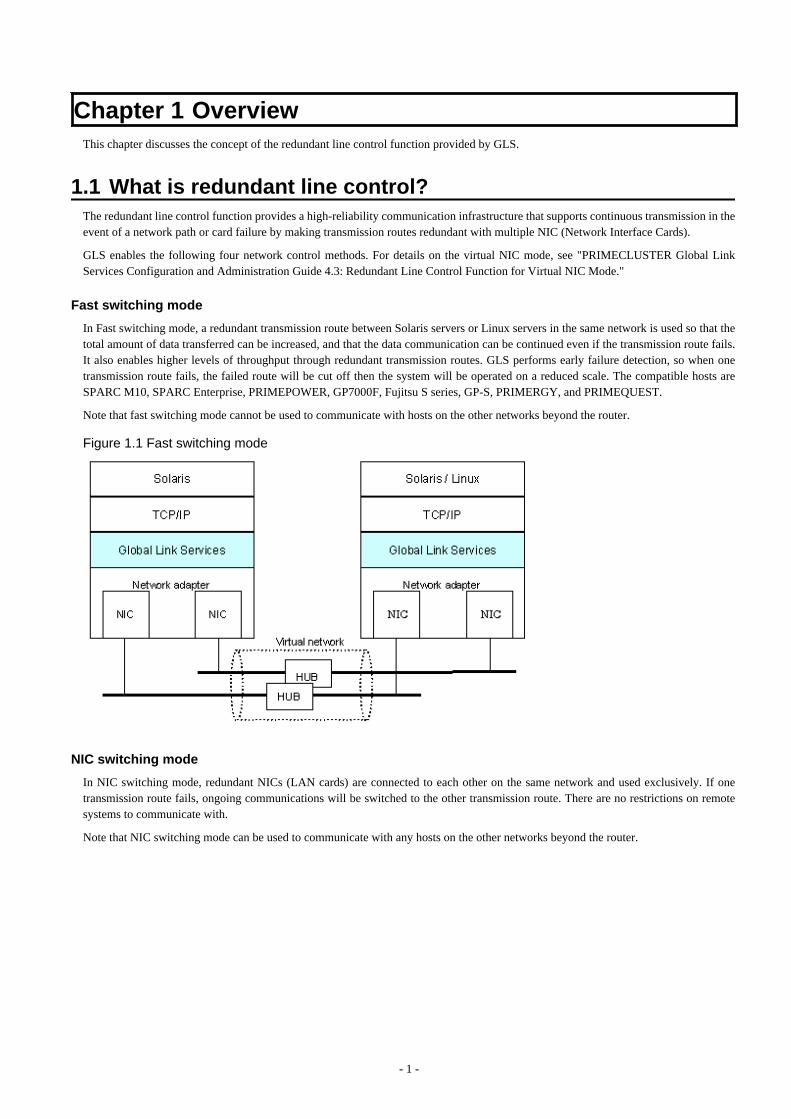
Chapter 1 OverviewThis chapter discusses the concept of the redundant line control function provided by GLS.
1.1 What is redundant line control?The redundant line control function provides a high-reliability communication infrastructure that supports continuous transmission in theevent of a network path or card failure by making transmission routes redundant with multiple NIC (Network Interface Cards).
GLS enables the following four network control methods. For details on the virtual NIC mode, see "PRIMECLUSTER Global LinkServices Configuration and Administration Guide 4.3: Redundant Line Control Function for Virtual NIC Mode."
Fast switching mode
In Fast switching mode, a redundant transmission route between Solaris servers or Linux servers in the same network is used so that thetotal amount of data transferred can be increased, and that the data communication can be continued even if the transmission route fails.It also enables higher levels of throughput through redundant transmission routes. GLS performs early failure detection, so when onetransmission route fails, the failed route will be cut off then the system will be operated on a reduced scale. The compatible hosts areSPARC M10, SPARC Enterprise, PRIMEPOWER, GP7000F, Fujitsu S series, GP-S, PRIMERGY, and PRIMEQUEST.
Note that fast switching mode cannot be used to communicate with hosts on the other networks beyond the router.
Figure 1.1 Fast switching mode
NIC switching mode
In NIC switching mode, redundant NICs (LAN cards) are connected to each other on the same network and used exclusively. If onetransmission route fails, ongoing communications will be switched to the other transmission route. There are no restrictions on remotesystems to communicate with.
Note that NIC switching mode can be used to communicate with any hosts on the other networks beyond the router.
- 1 -
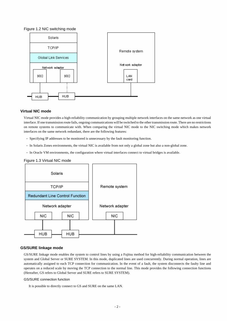
Figure 1.2 NIC switching mode
Virtual NIC mode
Virtual NIC mode provides a high-reliability communication by grouping multiple network interfaces on the same network as one virtualinterface. If one transmission route fails, ongoing communications will be switched to the other transmission route. There are no restrictionson remote systems to communicate with. When comparing the virtual NIC mode to the NIC switching mode which makes networkinterfaces on the same network redundant, there are the following features:
- Specifying IP addresses to be monitored is unnecessary by the fault monitoring function.
- In Solaris Zones environments, the virtual NIC is available from not only a global zone but also a non-global zone.
- In Oracle VM environments, the configuration where virtual interfaces connect to virtual bridges is available.
Figure 1.3 Virtual NIC mode
GS/SURE linkage mode
GS/SURE linkage mode enables the system to control lines by using a Fujitsu method for high-reliability communication between thesystem and Global Server or SURE SYSTEM. In this mode, duplicated lines are used concurrently. During normal operation, lines areautomatically assigned to each TCP connection for communication. In the event of a fault, the system disconnects the faulty line andoperates on a reduced scale by moving the TCP connection to the normal line. This mode provides the following connection functions(Hereafter, GS refers to Global Server and SURE refers to SURE SYSTEM).
GS/SURE connection function
It is possible to directly connect to GS and SURE on the same LAN.
- 2 -
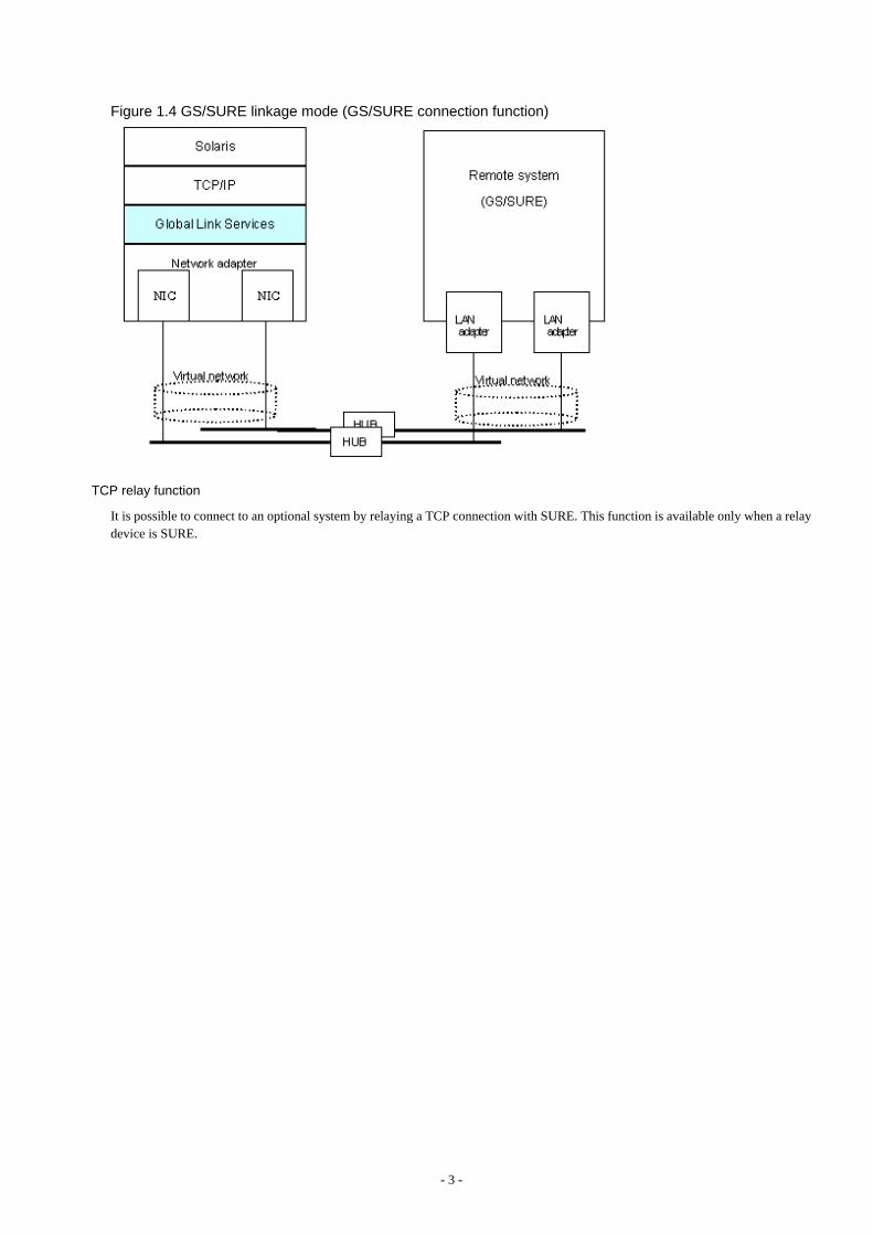
Figure 1.4 GS/SURE linkage mode (GS/SURE connection function)
TCP relay function
It is possible to connect to an optional system by relaying a TCP connection with SURE. This function is available only when a relaydevice is SURE.
- 3 -
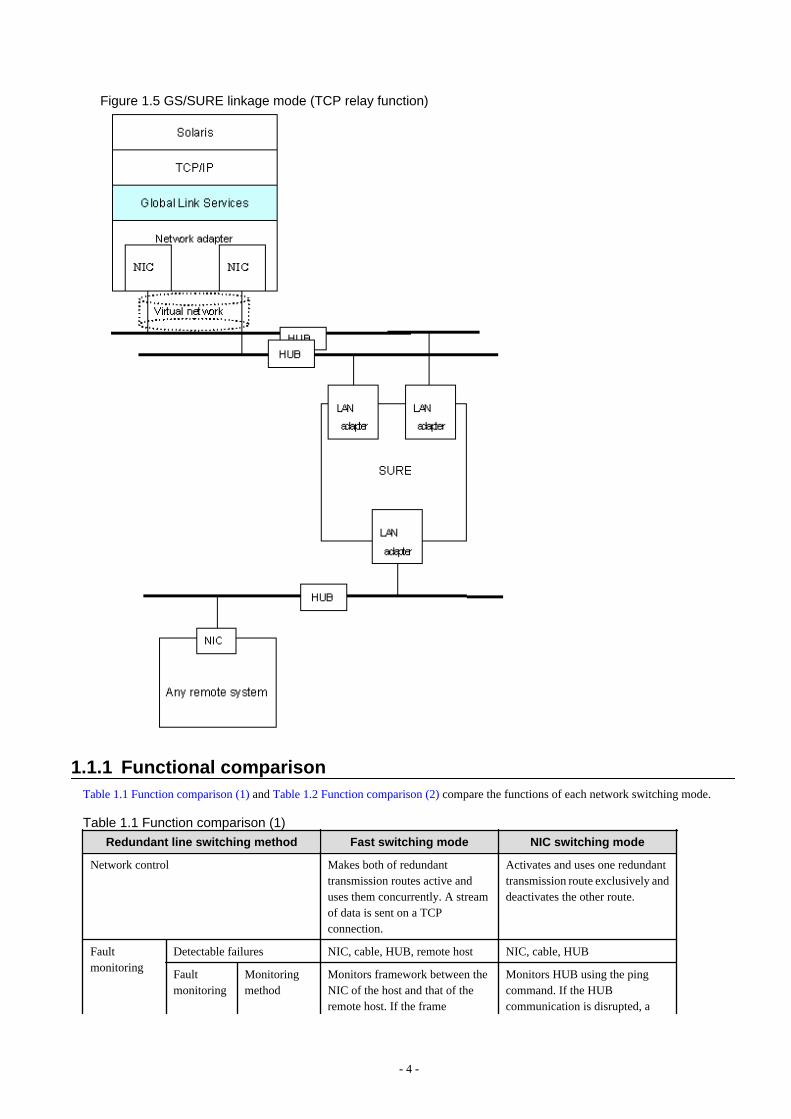
Figure 1.5 GS/SURE linkage mode (TCP relay function)
1.1.1 Functional comparisonTable 1.1 Function comparison (1) and Table 1.2 Function comparison (2) compare the functions of each network switching mode.
Table 1.1 Function comparison (1)
Redundant line switching method Fast switching mode NIC switching mode
Network control Makes both of redundanttransmission routes active anduses them concurrently. A streamof data is sent on a TCPconnection.
Activates and uses one redundanttransmission route exclusively anddeactivates the other route.
Faultmonitoring
Detectable failures NIC, cable, HUB, remote host NIC, cable, HUB
Faultmonitoring
Monitoringmethod
Monitors framework between theNIC of the host and that of theremote host. If the frame
Monitors HUB using the pingcommand. If the HUBcommunication is disrupted, a
- 4 -

Redundant line switching method Fast switching mode NIC switching mode
communication is disrupted, atransmission route failure will bedetected.
transmission route failure will bedetected.
Failuredetection time
5 to 10 seconds (Default) - When an error is detected byping: 22 to 27 seconds(Default)
- When a NIC link down isdetected: 2 to 7 seconds(Default)
Recoverymonitoring
Recoverymonitoringmethod
Monitors framework between theNIC of the host and that of theremote host. If the framecommunication is disrupted, atransmission route failure will bedetected.
If a monitoring framework is sentfrom a standby NIC to an operatingNIC, and the standby NIC receivesa reply from the operating NICwithin a specified time,transmission route recovery willbe detected.
Recoverydetection time
1 to 5 seconds (Default) 1 to 15 seconds (Default)
Fault monitoringstart/stop
Automatically starts along withvirtual interface activation andstops along with its deactivation.
Automatically starts along withvirtual interface activation andstops along with its deactivation.Manual startup or stop of faultmonitoring is also allowed with theoperational command.
Lineswitching
Switchover Automatically disconnects a failedtransmission route and uses theother transmission route.Manual disconnection of the failedroute is also allowed with theoperational command.
Automatically deactivates NIC ofa failed transmission route andactivates a standby NIC.Manual switching operation is alsoallowed with the operationalcommand.
Switchback If a failed transmission route isrecovered, it will automaticallyrejoin an ongoing operation.Manual rejoining is also allowedwith the operational command.
If a failed transmission route isrecovered, it will automaticallyrejoin operation as a standby NIC.Manual rejoining is also allowedwith the operational command.
Conditions Remote hosts SPARC M10, SPARC Enterprise,PRIMEPOWER, GP7000F, GP-S,Fujitsu S series, PRIMERGY,PRIMEQUEST
Arbitrary host
IP addresses IPv4 address, IPv6 address IPv4 address, IPv6 address
Solaris Zones Operated on a global zone.Ensures a high-reliabilitycommunication infrastructure onboth of the global and non-globalzones.
Operated on a global zone or non-global zones. Ensures a high-reliability communicationinfrastructure on both of the globaland non-global zones.
- 5 -
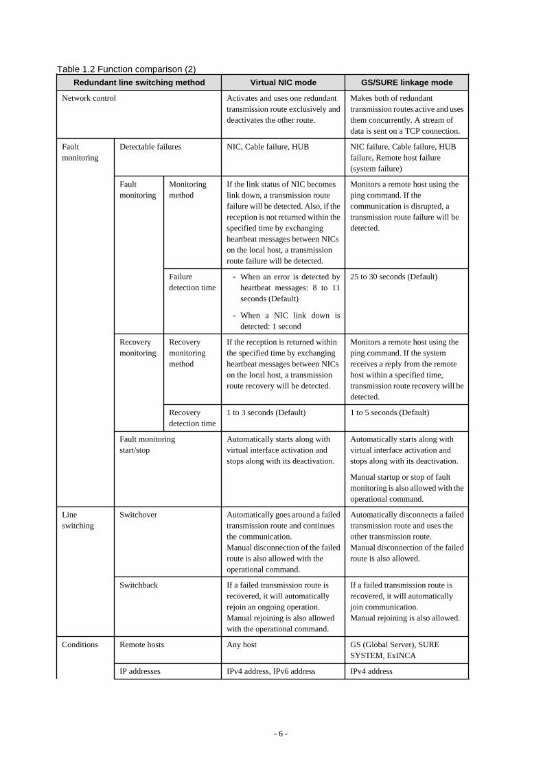
Table 1.2 Function comparison (2)Redundant line switching method Virtual NIC mode GS/SURE linkage mode
Network control Activates and uses one redundanttransmission route exclusively anddeactivates the other route.
Makes both of redundanttransmission routes active and usesthem concurrently. A stream ofdata is sent on a TCP connection.
Faultmonitoring
Detectable failures NIC, Cable failure, HUB NIC failure, Cable failure, HUBfailure, Remote host failure(system failure)
Faultmonitoring
Monitoringmethod
If the link status of NIC becomeslink down, a transmission routefailure will be detected. Also, if thereception is not returned within thespecified time by exchangingheartbeat messages between NICson the local host, a transmissionroute failure will be detected.
Monitors a remote host using theping command. If thecommunication is disrupted, atransmission route failure will bedetected.
Failuredetection time
- When an error is detected byheartbeat messages: 8 to 11seconds (Default)
- When a NIC link down isdetected: 1 second
25 to 30 seconds (Default)
Recoverymonitoring
Recoverymonitoringmethod
If the reception is returned withinthe specified time by exchangingheartbeat messages between NICson the local host, a transmissionroute recovery will be detected.
Monitors a remote host using theping command. If the systemreceives a reply from the remotehost within a specified time,transmission route recovery will bedetected.
Recoverydetection time
1 to 3 seconds (Default) 1 to 5 seconds (Default)
Fault monitoringstart/stop
Automatically starts along withvirtual interface activation andstops along with its deactivation.
Automatically starts along withvirtual interface activation andstops along with its deactivation.
Manual startup or stop of faultmonitoring is also allowed with theoperational command.
Lineswitching
Switchover Automatically goes around a failedtransmission route and continuesthe communication.Manual disconnection of the failedroute is also allowed with theoperational command.
Automatically disconnects a failedtransmission route and uses theother transmission route.Manual disconnection of the failedroute is also allowed.
Switchback If a failed transmission route isrecovered, it will automaticallyrejoin an ongoing operation.Manual rejoining is also allowedwith the operational command.
If a failed transmission route isrecovered, it will automaticallyjoin communication.Manual rejoining is also allowed.
Conditions Remote hosts Any host GS (Global Server), SURESYSTEM, ExINCA
IP addresses IPv4 address, IPv6 address IPv4 address
- 6 -
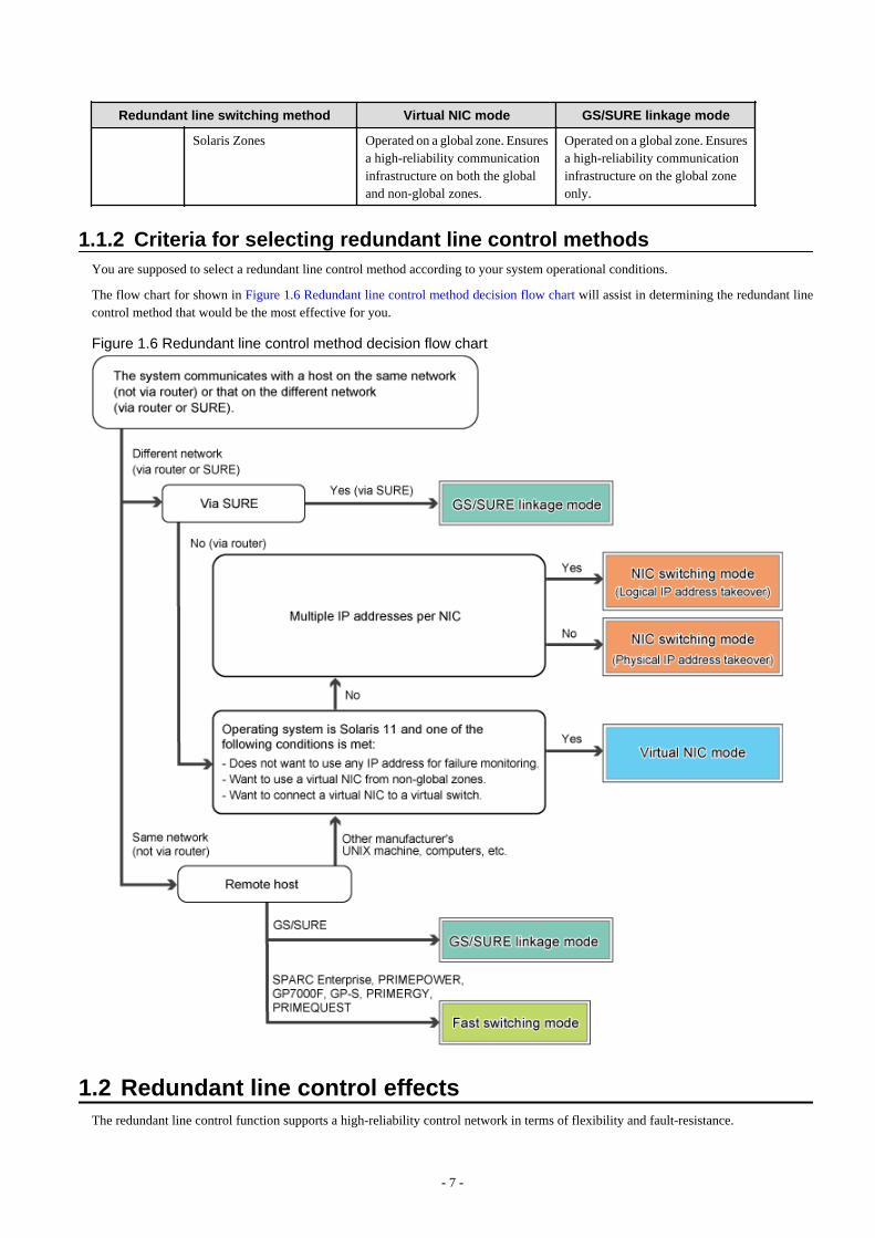
Redundant line switching method Virtual NIC mode GS/SURE linkage mode
Solaris Zones Operated on a global zone. Ensuresa high-reliability communicationinfrastructure on both the globaland non-global zones.
Operated on a global zone. Ensuresa high-reliability communicationinfrastructure on the global zoneonly.
1.1.2 Criteria for selecting redundant line control methodsYou are supposed to select a redundant line control method according to your system operational conditions.
The flow chart for shown in Figure 1.6 Redundant line control method decision flow chart will assist in determining the redundant linecontrol method that would be the most effective for you.
Figure 1.6 Redundant line control method decision flow chart
1.2 Redundant line control effectsThe redundant line control function supports a high-reliability control network in terms of flexibility and fault-resistance.
- 7 -
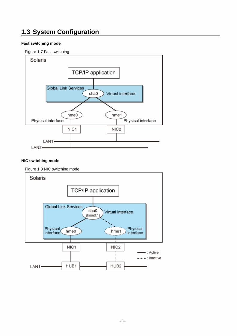
1.3 System Configuration
Fast switching mode
Figure 1.7 Fast switching
NIC switching mode
Figure 1.8 NIC switching mode
- 8 -
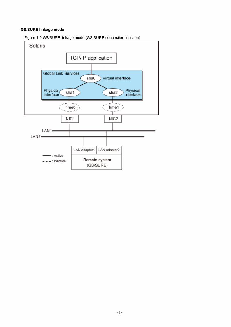
GS/SURE linkage mode
Figure 1.9 GS/SURE linkage mode (GS/SURE connection function)
- 9 -
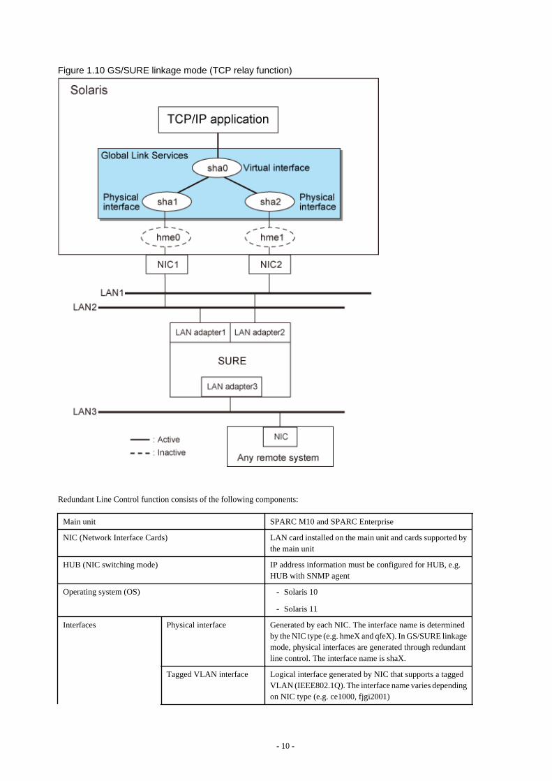
Figure 1.10 GS/SURE linkage mode (TCP relay function)
Redundant Line Control function consists of the following components:
Main unit SPARC M10 and SPARC Enterprise
NIC (Network Interface Cards) LAN card installed on the main unit and cards supported bythe main unit
HUB (NIC switching mode) IP address information must be configured for HUB, e.g.HUB with SNMP agent
Operating system (OS) - Solaris 10
- Solaris 11
Interfaces Physical interface Generated by each NIC. The interface name is determinedby the NIC type (e.g. hmeX and qfeX). In GS/SURE linkagemode, physical interfaces are generated through redundantline control. The interface name is shaX.
Tagged VLAN interface Logical interface generated by NIC that supports a taggedVLAN (IEEE802.1Q). The interface name varies dependingon NIC type (e.g. ce1000, fjgi2001)
- 10 -
Virtual interface Generated through redundant line control (e.g. sha0 andsha1).
Network applications can communicate using a virtual IPaddress assigned to the virtual interface.
In NIC switching, the virtual interface name is usedtechnically although no virtual interface is generated. Alogical IP is allocated to the actual network so that thenetwork applications enable communication through thelogical IP address.
Other interfaces Link aggregation interfaces (aggr0, aggr1, etc.) and virtualNICs (vnic0, vnic1, etc.) connected to a virtual bridge areavailable.
Network number Fast switching mode andGS/SURE linkage mode
A different network number is assigned to each physicalinterface and a virtual interface.In Figure 1.7 Fast switching, three network numbers mustbe prepared for the three interfaces.
NIC switching mode Only one number is assigned to each network. No virtualinterface is generated
IP address Fast switching mode An IP address must be allocated to each physical interfaceand a virtual interface. If there are two or more virtualinterfaces, an IP address will be allocated to each virtualinterface. Both IPv4 address and IPv6 address can be used.
NIC switching mode An IP address must be allocated to each logical interface. Ifthere are two or more logical interfaces, an IP address willbe allocated to each logical interface. Both IPv4 address andIPv6 address can be used.
GS/SURE linkage mode An IP address must be allocated to each physical interfaceand a virtual interface. If there are two or more virtualinterfaces, an IP address will be allocated to each virtualinterface. Only IPv4 can be used.
- 11 -
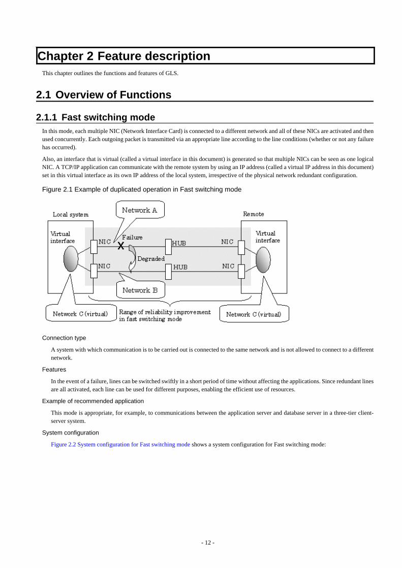
Chapter 2 Feature descriptionThis chapter outlines the functions and features of GLS.
2.1 Overview of Functions
2.1.1 Fast switching modeIn this mode, each multiple NIC (Network Interface Card) is connected to a different network and all of these NICs are activated and thenused concurrently. Each outgoing packet is transmitted via an appropriate line according to the line conditions (whether or not any failurehas occurred).
Also, an interface that is virtual (called a virtual interface in this document) is generated so that multiple NICs can be seen as one logicalNIC. A TCP/IP application can communicate with the remote system by using an IP address (called a virtual IP address in this document)set in this virtual interface as its own IP address of the local system, irrespective of the physical network redundant configuration.
Figure 2.1 Example of duplicated operation in Fast switching mode
Connection type
A system with which communication is to be carried out is connected to the same network and is not allowed to connect to a differentnetwork.
Features
In the event of a failure, lines can be switched swiftly in a short period of time without affecting the applications. Since redundant linesare all activated, each line can be used for different purposes, enabling the efficient use of resources.
Example of recommended application
This mode is appropriate, for example, to communications between the application server and database server in a three-tier client-server system.
System configuration
Figure 2.2 System configuration for Fast switching mode shows a system configuration for Fast switching mode:
- 12 -
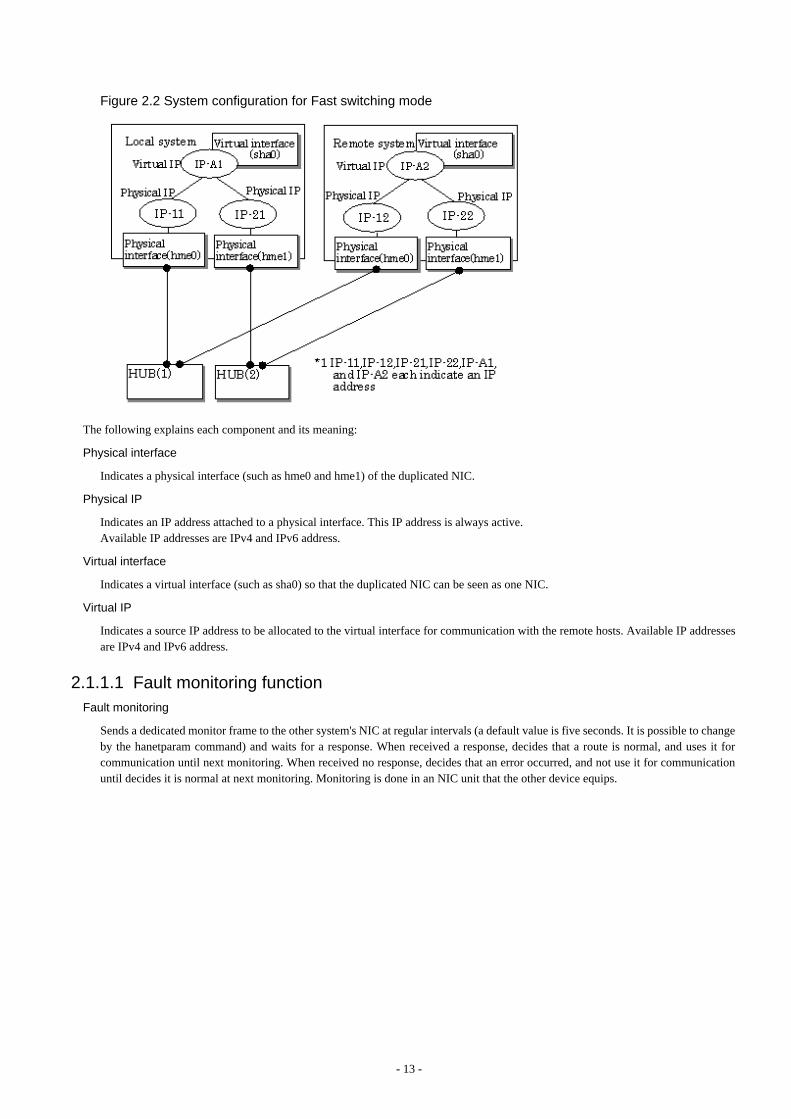
Figure 2.2 System configuration for Fast switching mode
The following explains each component and its meaning:
Physical interface
Indicates a physical interface (such as hme0 and hme1) of the duplicated NIC.
Physical IP
Indicates an IP address attached to a physical interface. This IP address is always active.Available IP addresses are IPv4 and IPv6 address.
Virtual interface
Indicates a virtual interface (such as sha0) so that the duplicated NIC can be seen as one NIC.
Virtual IP
Indicates a source IP address to be allocated to the virtual interface for communication with the remote hosts. Available IP addressesare IPv4 and IPv6 address.
2.1.1.1 Fault monitoring functionFault monitoring
Sends a dedicated monitor frame to the other system's NIC at regular intervals (a default value is five seconds. It is possible to changeby the hanetparam command) and waits for a response. When received a response, decides that a route is normal, and uses it forcommunication until next monitoring. When received no response, decides that an error occurred, and not use it for communicationuntil decides it is normal at next monitoring. Monitoring is done in an NIC unit that the other device equips.
- 13 -
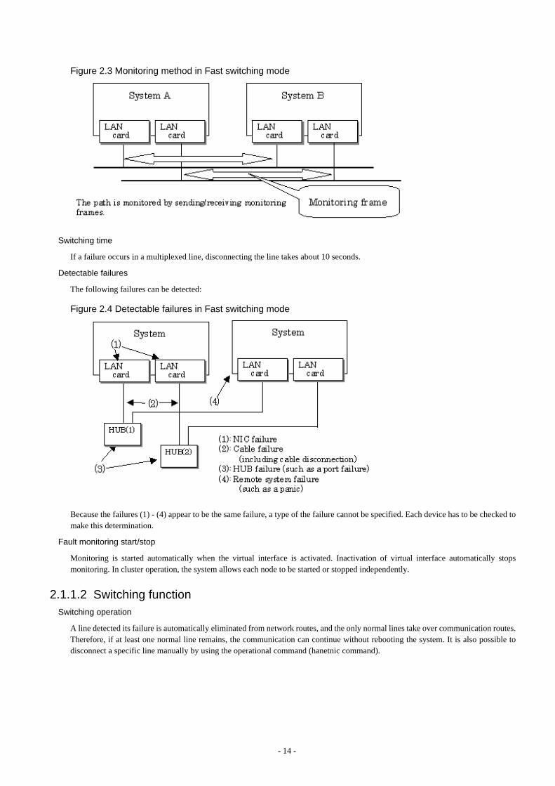
Figure 2.3 Monitoring method in Fast switching mode
Switching time
If a failure occurs in a multiplexed line, disconnecting the line takes about 10 seconds.
Detectable failures
The following failures can be detected:
Figure 2.4 Detectable failures in Fast switching mode
Because the failures (1) - (4) appear to be the same failure, a type of the failure cannot be specified. Each device has to be checked tomake this determination.
Fault monitoring start/stop
Monitoring is started automatically when the virtual interface is activated. Inactivation of virtual interface automatically stopsmonitoring. In cluster operation, the system allows each node to be started or stopped independently.
2.1.1.2 Switching functionSwitching operation
A line detected its failure is automatically eliminated from network routes, and the only normal lines take over communication routes.Therefore, if at least one normal line remains, the communication can continue without rebooting the system. It is also possible todisconnect a specific line manually by using the operational command (hanetnic command).
- 14 -
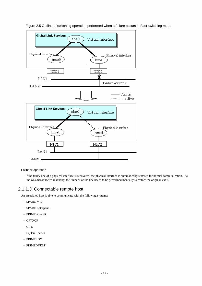
Figure 2.5 Outline of switching operation performed when a failure occurs in Fast switching mode
Failback operation
If the faulty line of a physical interface is recovered, the physical interface is automatically restored for normal communication. If aline was disconnected manually, the failback of the line needs to be performed manually to restore the original status.
2.1.1.3 Connectable remote hostAn associated host is able to communicate with the following systems:
- SPARC M10
- SPARC Enterprise
- PRIMEPOWER
- GP7000F
- GP-S
- Fujitsu S series
- PRIMERGY
- PRIMEQUEST
- 15 -

2.1.1.4 Available applicationThe requirement for user applications that can be operated in this mode is as follows:
- Application using the TCP or UDP.
2.1.1.5 Notes- When assigning IPv4 address to the virtual interface, IPv4 address must be assigned to all the redundant physical interfaces.
- If assigning IPv6 address to the virtual interface, IPv6 address must be assigned to all the redundant physical interfaces.
- If assigning both IPv4 and IPv6 to the virtual interface, these two forms of an IP address must be assigned to all the redundant physicalinterfaces.
- No multi-cast IP address can be used.
- Do not change the name of the virtual interface and the interface that is made redundant with the virtual interface. If names are changed,virtual interfaces are not properly activated and deactivated.
2.1.2 NIC switching modeIn this mode, duplicated NICs are connected to the same network and switching control of lines is performed based on the exclusive use(During normal operation, one NIC is made to go "up" for communication). A TCP/IP application can conduct communication with theremote system, irrespective of NIC switching, by using an IP address set in this "up" physical interface as its own local system IP address.
Figure 2.6 Example of duplicated operation in NIC switching mode
Information
NIC switching mode handles logical interface as a takeover interface. When using physical interfaces hme0 and hme1, the takeoverinterface becomes hme0:1 and hme1:1. Note that it is possible to takeover physical interface without using logical interface. Look undersection "2.1.2.2 Switching function" for details on NIC switching mode.
Connection type
Duplicated NICs are connected to the same network. The remote system with which communication is to be carried out can be connectedto either the same network or a different network via routers.
Features
If each network device (such as the HUB and routers) has the duplicating function in a multi-vendor environment, this mode is effectivewhen improving overall reliability in combination with these devices. In this case, the range of duplication is defined for each vendor.
- 16 -
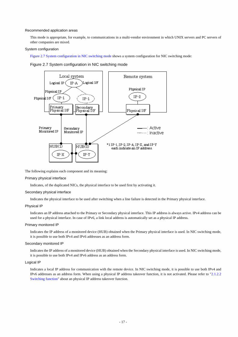
Recommended application areas
This mode is appropriate, for example, to communications in a multi-vendor environment in which UNIX servers and PC servers ofother companies are mixed.
System configuration
Figure 2.7 System configuration in NIC switching mode shows a system configuration for NIC switching mode:
Figure 2.7 System configuration in NIC switching mode
The following explains each component and its meaning:
Primary physical interface
Indicates, of the duplicated NICs, the physical interface to be used first by activating it.
Secondary physical interface
Indicates the physical interface to be used after switching when a line failure is detected in the Primary physical interface.
Physical IP
Indicates an IP address attached to the Primary or Secondary physical interface. This IP address is always active. IPv4 address can beused for a physical interface. In case of IPv6, a link local address is automatically set as a physical IP address.
Primary monitored IP
Indicates the IP address of a monitored device (HUB) obtained when the Primary physical interface is used. In NIC switching mode,it is possible to use both IPv4 and IPv6 addresses as an address form.
Secondary monitored IP
Indicates the IP address of a monitored device (HUB) obtained when the Secondary physical interface is used. In NIC switching mode,it is possible to use both IPv4 and IPv6 address as an address form.
Logical IP
Indicates a local IP address for communication with the remote device. In NIC switching mode, it is possible to use both IPv4 andIPv6 addresses as an address form. When using a physical IP address takeover function, it is not activated. Please refer to "2.1.2.2Switching function" about an physical IP address takeover function.
- 17 -

2.1.2.1 Fault monitoring functionFault monitoring
The ping command is issued periodically to the HUB connected to the NIC currently operating and its response is monitored. Optionally,HUB-to-HUB communication can be monitored.
If a failure is detected in the NIC currently operating, the system switches to the standby NIC and similar monitoring starts from thestandby NIC side. Then, if a failure is also detected with the standby NIC, line monitoring stops.
When using a standby patrol function, monitoring starts automatically at the recovery of all transfer routes.
Figure 2.8 Monitoring method in NIC switching mode
Switching time
The estimated switching time of a line is indicated by "monitoring interval (sec)" multiplied by "monitoring count (count)." Themonitoring interval can be set in the range of 1 to 300 seconds and the monitoring count can be set in the range of 1 to 300 times. Bydefault, they are 5 seconds and 5 times respectively. For details, see "3.6.6.3 Transfer route error detection time for NIC switchingmode." Even if the ping command failed immediately after started monitoring, it is not regarded as a communication line failure until thewaiting time (sec) for the Ethernet linkup passed. It is possible to set the waiting time for linkup in a range of 1 to 300 seconds and adefault value is 60 seconds. However, if the specified value is less than "monitoring interval" multiplied by "monitoring count," thesystem ignores the specified link-up time and adopts the time calculated by multiplying "monitoring interval" by "monitoring count."
Figure 2.9 Fault detection time in NIC switching mode
Detectable failures
The following failures can be detected:
- 18 -
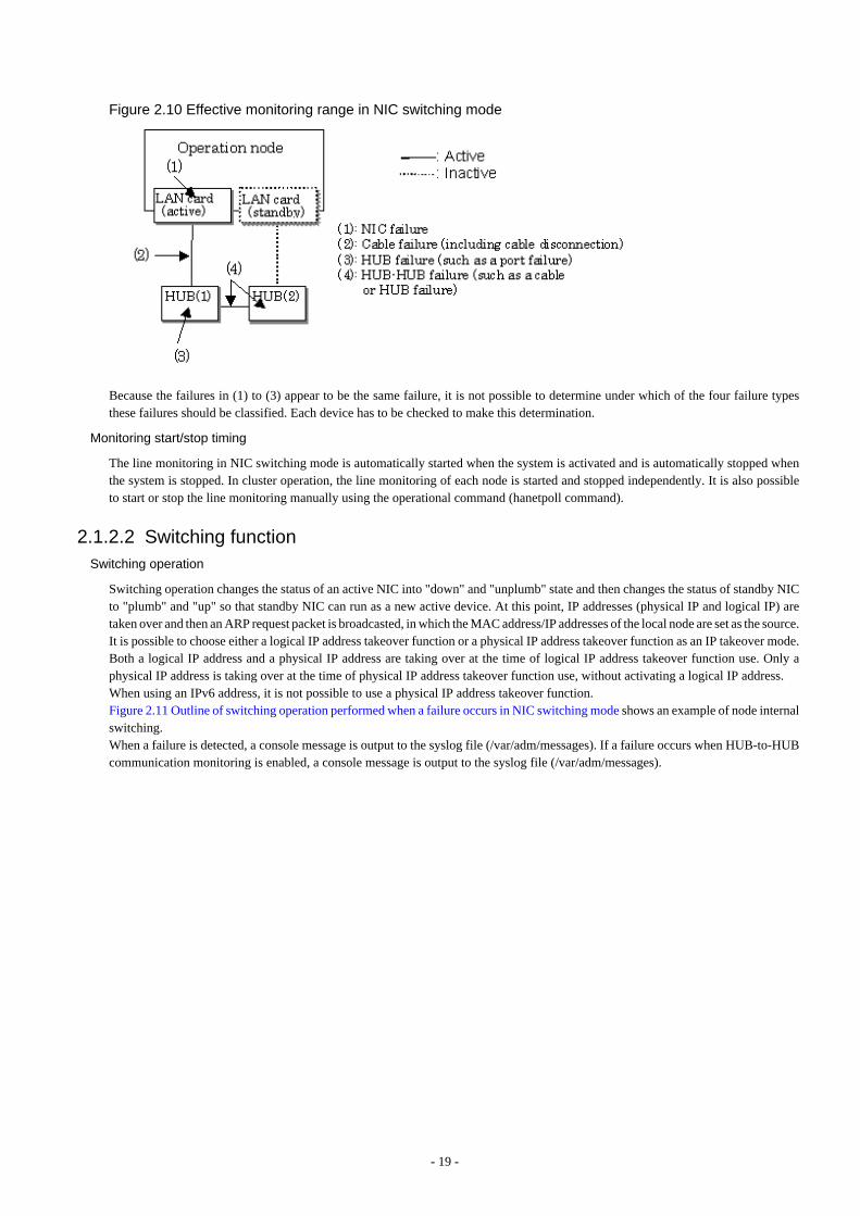
Figure 2.10 Effective monitoring range in NIC switching mode
Because the failures in (1) to (3) appear to be the same failure, it is not possible to determine under which of the four failure typesthese failures should be classified. Each device has to be checked to make this determination.
Monitoring start/stop timing
The line monitoring in NIC switching mode is automatically started when the system is activated and is automatically stopped whenthe system is stopped. In cluster operation, the line monitoring of each node is started and stopped independently. It is also possibleto start or stop the line monitoring manually using the operational command (hanetpoll command).
2.1.2.2 Switching functionSwitching operation
Switching operation changes the status of an active NIC into "down" and "unplumb" state and then changes the status of standby NICto "plumb" and "up" so that standby NIC can run as a new active device. At this point, IP addresses (physical IP and logical IP) aretaken over and then an ARP request packet is broadcasted, in which the MAC address/IP addresses of the local node are set as the source.It is possible to choose either a logical IP address takeover function or a physical IP address takeover function as an IP takeover mode.Both a logical IP address and a physical IP address are taking over at the time of logical IP address takeover function use. Only aphysical IP address is taking over at the time of physical IP address takeover function use, without activating a logical IP address.When using an IPv6 address, it is not possible to use a physical IP address takeover function.Figure 2.11 Outline of switching operation performed when a failure occurs in NIC switching mode shows an example of node internalswitching.When a failure is detected, a console message is output to the syslog file (/var/adm/messages). If a failure occurs when HUB-to-HUBcommunication monitoring is enabled, a console message is output to the syslog file (/var/adm/messages).
- 19 -
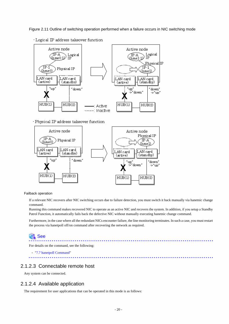
Figure 2.11 Outline of switching operation performed when a failure occurs in NIC switching mode
Failback operation
If a relevant NIC recovers after NIC switching occurs due to failure detection, you must switch it back manually via hanetnic changecommand.Running this command makes recovered NIC to operate as an active NIC and recovers the system. In addition, if you setup a StandbyPatrol Function, it automatically fails back the defective NIC without manually executing hanetnic change command.
Furthermore, in the case where all the redundant NICs encounter failure, the line monitoring terminates. In such a case, you must restartthe process via hanetpoll off/on command after recovering the network as required.
See
For details on the command, see the following:
- "7.7 hanetpoll Command"
2.1.2.3 Connectable remote hostAny system can be connected.
2.1.2.4 Available applicationThe requirement for user applications that can be operated in this mode is as follows:
- 20 -
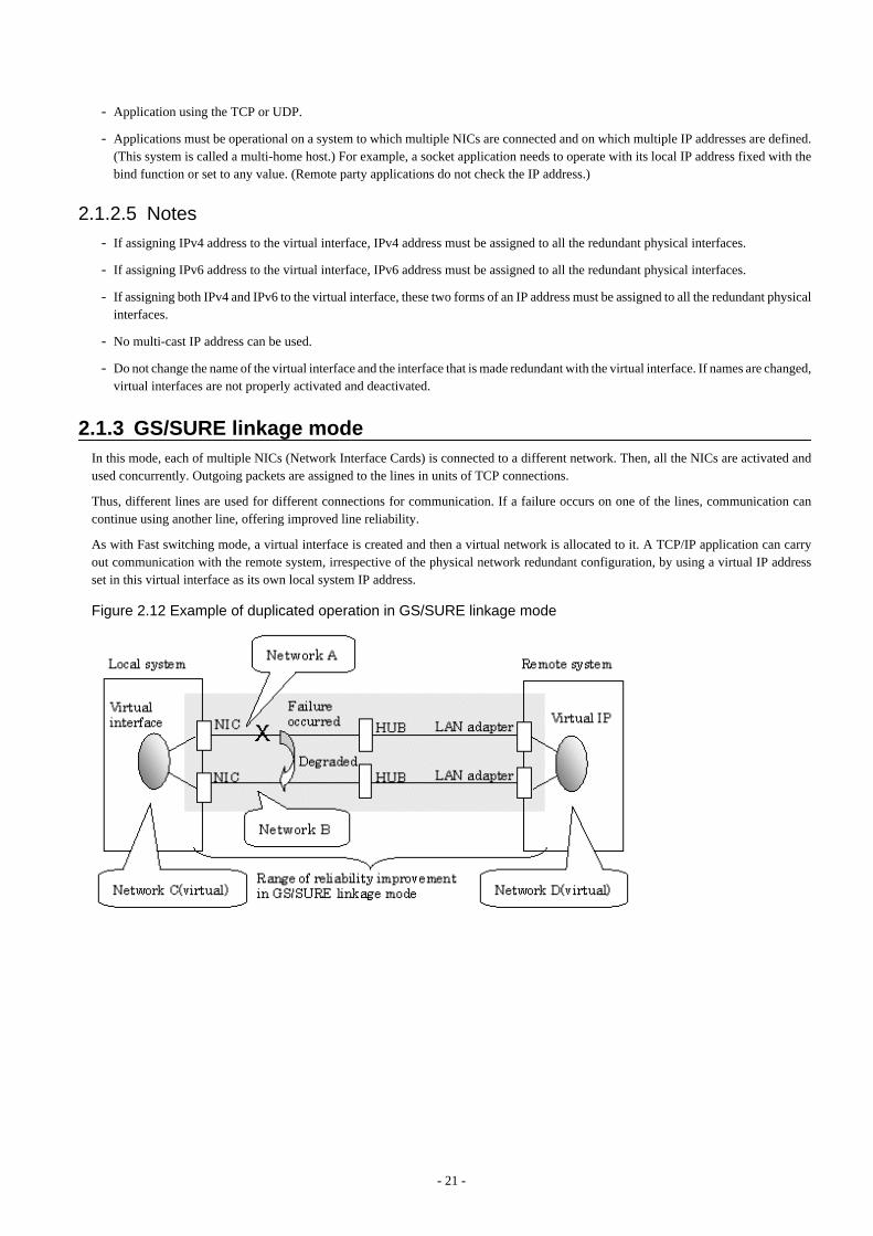
- Application using the TCP or UDP.
- Applications must be operational on a system to which multiple NICs are connected and on which multiple IP addresses are defined.(This system is called a multi-home host.) For example, a socket application needs to operate with its local IP address fixed with thebind function or set to any value. (Remote party applications do not check the IP address.)
2.1.2.5 Notes- If assigning IPv4 address to the virtual interface, IPv4 address must be assigned to all the redundant physical interfaces.
- If assigning IPv6 address to the virtual interface, IPv6 address must be assigned to all the redundant physical interfaces.
- If assigning both IPv4 and IPv6 to the virtual interface, these two forms of an IP address must be assigned to all the redundant physicalinterfaces.
- No multi-cast IP address can be used.
- Do not change the name of the virtual interface and the interface that is made redundant with the virtual interface. If names are changed,virtual interfaces are not properly activated and deactivated.
2.1.3 GS/SURE linkage modeIn this mode, each of multiple NICs (Network Interface Cards) is connected to a different network. Then, all the NICs are activated andused concurrently. Outgoing packets are assigned to the lines in units of TCP connections.
Thus, different lines are used for different connections for communication. If a failure occurs on one of the lines, communication cancontinue using another line, offering improved line reliability.
As with Fast switching mode, a virtual interface is created and then a virtual network is allocated to it. A TCP/IP application can carryout communication with the remote system, irrespective of the physical network redundant configuration, by using a virtual IP addressset in this virtual interface as its own local system IP address.
Figure 2.12 Example of duplicated operation in GS/SURE linkage mode
- 21 -
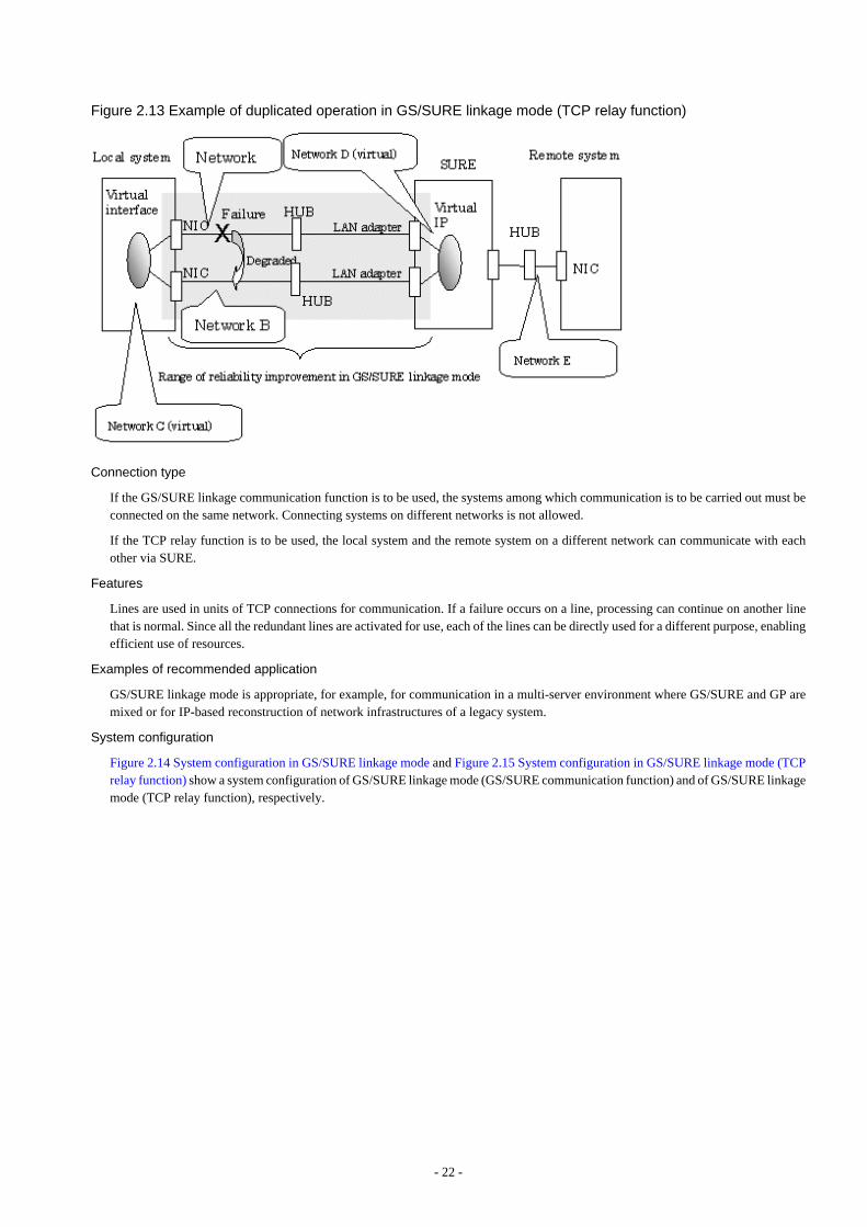
Figure 2.13 Example of duplicated operation in GS/SURE linkage mode (TCP relay function)
Connection type
If the GS/SURE linkage communication function is to be used, the systems among which communication is to be carried out must beconnected on the same network. Connecting systems on different networks is not allowed.
If the TCP relay function is to be used, the local system and the remote system on a different network can communicate with eachother via SURE.
Features
Lines are used in units of TCP connections for communication. If a failure occurs on a line, processing can continue on another linethat is normal. Since all the redundant lines are activated for use, each of the lines can be directly used for a different purpose, enablingefficient use of resources.
Examples of recommended application
GS/SURE linkage mode is appropriate, for example, for communication in a multi-server environment where GS/SURE and GP aremixed or for IP-based reconstruction of network infrastructures of a legacy system.
System configuration
Figure 2.14 System configuration in GS/SURE linkage mode and Figure 2.15 System configuration in GS/SURE linkage mode (TCPrelay function) show a system configuration of GS/SURE linkage mode (GS/SURE communication function) and of GS/SURE linkagemode (TCP relay function), respectively.
- 22 -
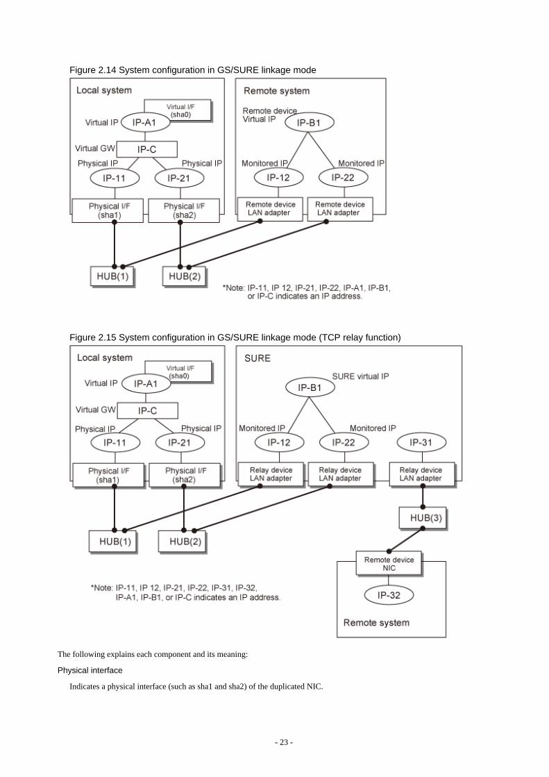
Figure 2.14 System configuration in GS/SURE linkage mode
Figure 2.15 System configuration in GS/SURE linkage mode (TCP relay function)
The following explains each component and its meaning:
Physical interface
Indicates a physical interface (such as sha1 and sha2) of the duplicated NIC.
- 23 -
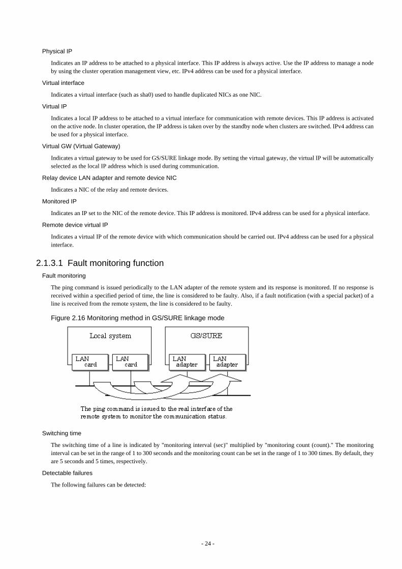
Physical IP
Indicates an IP address to be attached to a physical interface. This IP address is always active. Use the IP address to manage a nodeby using the cluster operation management view, etc. IPv4 address can be used for a physical interface.
Virtual interface
Indicates a virtual interface (such as sha0) used to handle duplicated NICs as one NIC.
Virtual IP
Indicates a local IP address to be attached to a virtual interface for communication with remote devices. This IP address is activatedon the active node. In cluster operation, the IP address is taken over by the standby node when clusters are switched. IPv4 address canbe used for a physical interface.
Virtual GW (Virtual Gateway)
Indicates a virtual gateway to be used for GS/SURE linkage mode. By setting the virtual gateway, the virtual IP will be automaticallyselected as the local IP address which is used during communication.
Relay device LAN adapter and remote device NIC
Indicates a NIC of the relay and remote devices.
Monitored IP
Indicates an IP set to the NIC of the remote device. This IP address is monitored. IPv4 address can be used for a physical interface.
Remote device virtual IP
Indicates a virtual IP of the remote device with which communication should be carried out. IPv4 address can be used for a physicalinterface.
2.1.3.1 Fault monitoring functionFault monitoring
The ping command is issued periodically to the LAN adapter of the remote system and its response is monitored. If no response isreceived within a specified period of time, the line is considered to be faulty. Also, if a fault notification (with a special packet) of aline is received from the remote system, the line is considered to be faulty.
Figure 2.16 Monitoring method in GS/SURE linkage mode
Switching time
The switching time of a line is indicated by "monitoring interval (sec)" multiplied by "monitoring count (count)." The monitoringinterval can be set in the range of 1 to 300 seconds and the monitoring count can be set in the range of 1 to 300 times. By default, theyare 5 seconds and 5 times, respectively.
Detectable failures
The following failures can be detected:
- 24 -
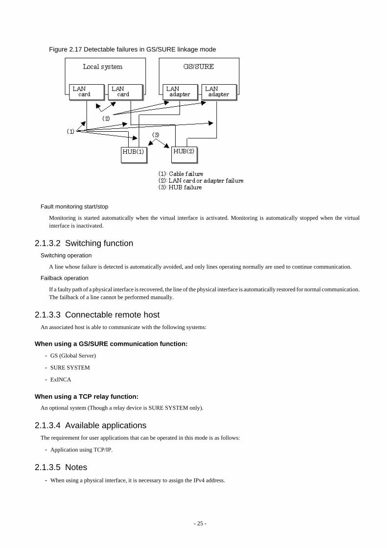
Figure 2.17 Detectable failures in GS/SURE linkage mode
Fault monitoring start/stop
Monitoring is started automatically when the virtual interface is activated. Monitoring is automatically stopped when the virtualinterface is inactivated.
2.1.3.2 Switching functionSwitching operation
A line whose failure is detected is automatically avoided, and only lines operating normally are used to continue communication.
Failback operation
If a faulty path of a physical interface is recovered, the line of the physical interface is automatically restored for normal communication.The failback of a line cannot be performed manually.
2.1.3.3 Connectable remote hostAn associated host is able to communicate with the following systems:
When using a GS/SURE communication function:
- GS (Global Server)
- SURE SYSTEM
- ExINCA
When using a TCP relay function:
An optional system (Though a relay device is SURE SYSTEM only).
2.1.3.4 Available applicationsThe requirement for user applications that can be operated in this mode is as follows:
- Application using TCP/IP.
2.1.3.5 Notes- When using a physical interface, it is necessary to assign the IPv4 address.
- 25 -
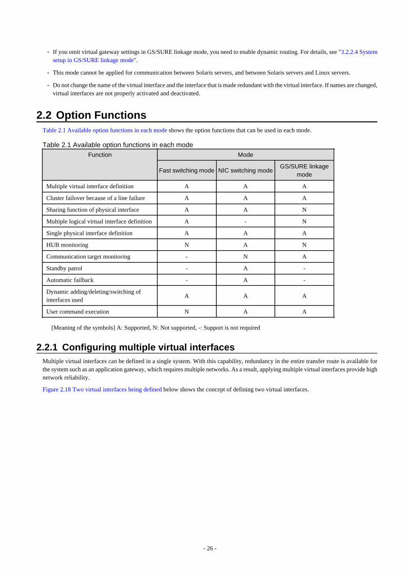
- If you omit virtual gateway settings in GS/SURE linkage mode, you need to enable dynamic routing. For details, see "3.2.2.4 Systemsetup in GS/SURE linkage mode".
- This mode cannot be applied for communication between Solaris servers, and between Solaris servers and Linux servers.
- Do not change the name of the virtual interface and the interface that is made redundant with the virtual interface. If names are changed,virtual interfaces are not properly activated and deactivated.
2.2 Option FunctionsTable 2.1 Available option functions in each mode shows the option functions that can be used in each mode.
Table 2.1 Available option functions in each mode
Function Mode
Fast switching mode NIC switching modeGS/SURE linkage
mode
Multiple virtual interface definition A A A
Cluster failover because of a line failure A A A
Sharing function of physical interface A A N
Multiple logical virtual interface definition A - N
Single physical interface definition A A A
HUB monitoring N A N
Communication target monitoring - N A
Standby patrol - A -
Automatic failback - A -
Dynamic adding/deleting/switching ofinterfaces used
A A A
User command execution N A A
[Meaning of the symbols] A: Supported, N: Not supported, -: Support is not required
2.2.1 Configuring multiple virtual interfacesMultiple virtual interfaces can be defined in a single system. With this capability, redundancy in the entire transfer route is available forthe system such as an application gateway, which requires multiple networks. As a result, applying multiple virtual interfaces provide highnetwork reliability.
Figure 2.18 Two virtual interfaces being defined below shows the concept of defining two virtual interfaces.
- 26 -
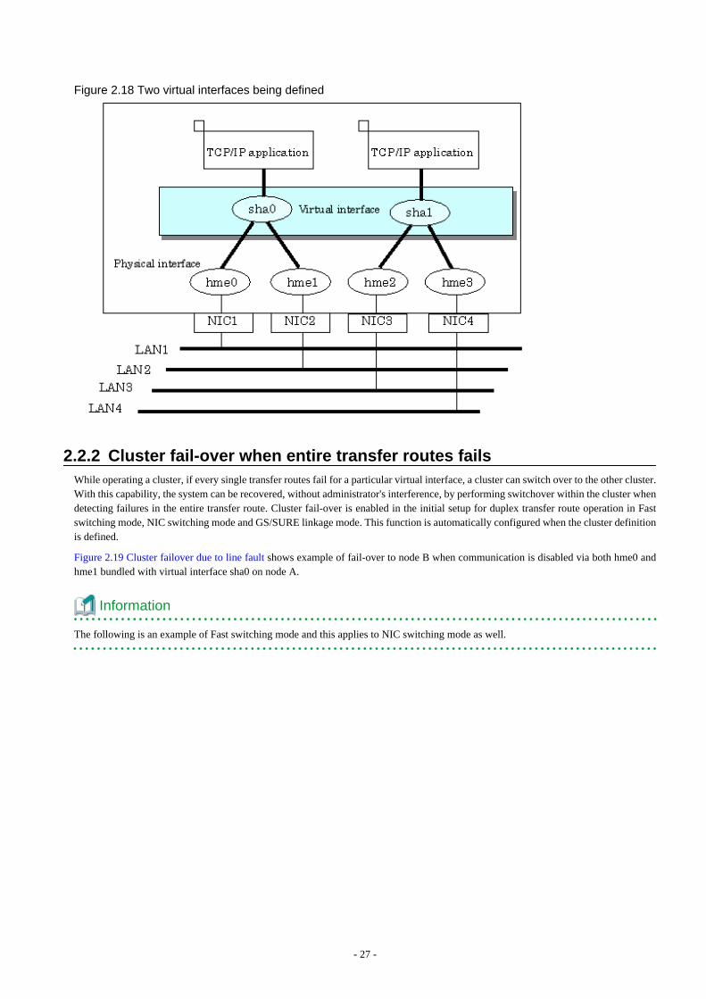
Figure 2.18 Two virtual interfaces being defined
2.2.2 Cluster fail-over when entire transfer routes failsWhile operating a cluster, if every single transfer routes fail for a particular virtual interface, a cluster can switch over to the other cluster.With this capability, the system can be recovered, without administrator's interference, by performing switchover within the cluster whendetecting failures in the entire transfer route. Cluster fail-over is enabled in the initial setup for duplex transfer route operation in Fastswitching mode, NIC switching mode and GS/SURE linkage mode. This function is automatically configured when the cluster definitionis defined.
Figure 2.19 Cluster failover due to line fault shows example of fail-over to node B when communication is disabled via both hme0 andhme1 bundled with virtual interface sha0 on node A.
Information
The following is an example of Fast switching mode and this applies to NIC switching mode as well.
- 27 -

Figure 2.19 Cluster failover due to line fault
2.2.3 Sharing physical interfaceIf multiple virtual interfaces are created, these interfaces can share one or all physical interfaces. This is called "sharing physical interface".
Using this capability, it is possible to:
- Decrease the number of NICs used for the redundancy operation, and make effective use of limited resource in Fast switching mode.
- Configuring multiple IP addresses on a single NIC in NIC switching mode and use different IP address for each application.
2.2.3.1 Using Fast switching modeIn the virtual interface, which institutes Fast switching mode, one portion or entire physical interfaces can be shared. Though, sharing isnot possible for the physical interface and virtual interface of NIC switching mode and GS/SURE linkage mode.
Figure 2.20 Example of sharing physical interface (1) shows an example of three virtual interfaces in Fast switching mode, sha0, sha1,and sha2 sharing three physical interfaces hme1, hme2, and hme3.
- 28 -
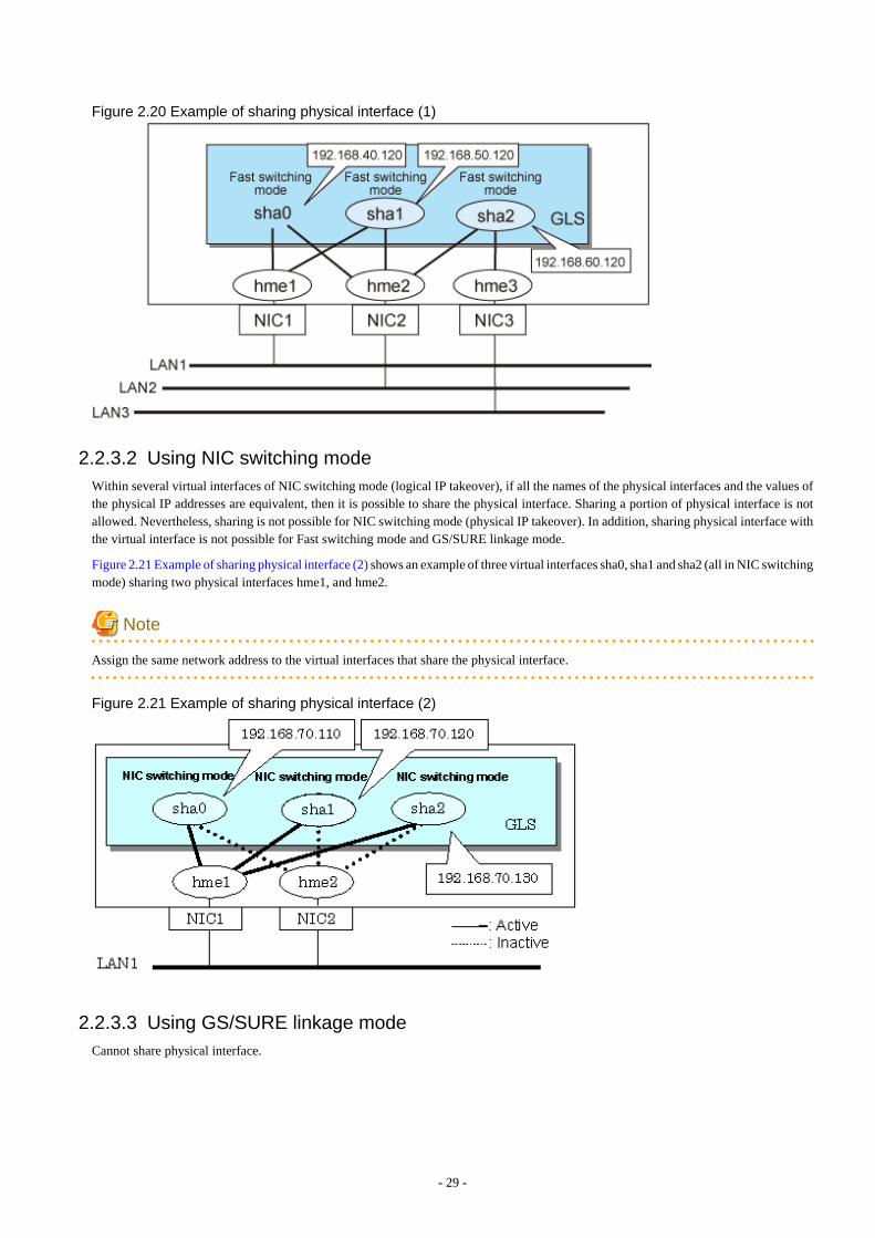
Figure 2.20 Example of sharing physical interface (1)
2.2.3.2 Using NIC switching modeWithin several virtual interfaces of NIC switching mode (logical IP takeover), if all the names of the physical interfaces and the values ofthe physical IP addresses are equivalent, then it is possible to share the physical interface. Sharing a portion of physical interface is notallowed. Nevertheless, sharing is not possible for NIC switching mode (physical IP takeover). In addition, sharing physical interface withthe virtual interface is not possible for Fast switching mode and GS/SURE linkage mode.
Figure 2.21 Example of sharing physical interface (2) shows an example of three virtual interfaces sha0, sha1 and sha2 (all in NIC switchingmode) sharing two physical interfaces hme1, and hme2.
Note
Assign the same network address to the virtual interfaces that share the physical interface.
Figure 2.21 Example of sharing physical interface (2)
2.2.3.3 Using GS/SURE linkage modeCannot share physical interface.
- 29 -

2.2.3.4 NoticesIn Fast switching mode, NIC sharing is not possible within the virtual interface that can have IPv6 address. NIC sharing is possible betweenthe virtual interfaces, which can have IPv4 address, or virtual interfaces, which can have IPv6 address and the virtual interfaces, whichcan have IPv4 address.
2.2.4 Configuring multiple logical virtual interfacesIt is possible to define several IP addresses (logical virtual interfaces) on a single virtual interface. Using this function, various IP addressescan be used for each application.
Figure 2.22 Logical virtual interfaces being defined shows an example of defining three IP addresses (logical virtual interface) on a singlevirtual interface sha0.
Figure 2.22 Logical virtual interfaces being defined
In the above figure, sha0:2 to sha0:4 are called logical virtual interfaces in this document. For each logical virtual interface, please assignthe address in the same subnet as the virtual interface where the logical virtual interface belongs. For operation on a cluster system, pleaseassign the address in the same subnet as the takeover address.
Note
- This function is only available for Fast switching mode. The other mode such as GS/SURE linkage mode does not apply.
- For NIC switching mode, if using physical interface sharing function, it can process (a process of allocating multiple IP addresses toone physical interface) equally as this function.
2.2.5 Configuring single physical interfaceYou can create a virtual interface, which has a single physical interface. This function enables failover because of a line failure even ona cluster system that has only one physical interface available for use.
Figure 2.23 Single physical interface configuration shows an example of single physical interface configuration.
- 30 -
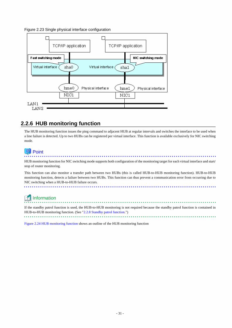
Figure 2.23 Single physical interface configuration
2.2.6 HUB monitoring functionThe HUB monitoring function issues the ping command to adjacent HUB at regular intervals and switches the interface to be used whena line failure is detected. Up to two HUBs can be registered per virtual interface. This function is available exclusively for NIC switchingmode.
Point
HUB monitoring function for NIC switching mode supports both configuration of the monitoring target for each virtual interface and start/stop of router monitoring.
This function can also monitor a transfer path between two HUBs (this is called HUB-to-HUB monitoring function). HUB-to-HUBmonitoring function, detects a failure between two HUBs. This function can thus prevent a communication error from occurring due toNIC switching when a HUB-to-HUB failure occurs.
Information
If the standby patrol function is used, the HUB-to-HUB monitoring is not required because the standby patrol function is contained inHUB-to-HUB monitoring function. (See "2.2.8 Standby patrol function.")
Figure 2.24 HUB monitoring function shows an outline of the HUB monitoring function
- 31 -
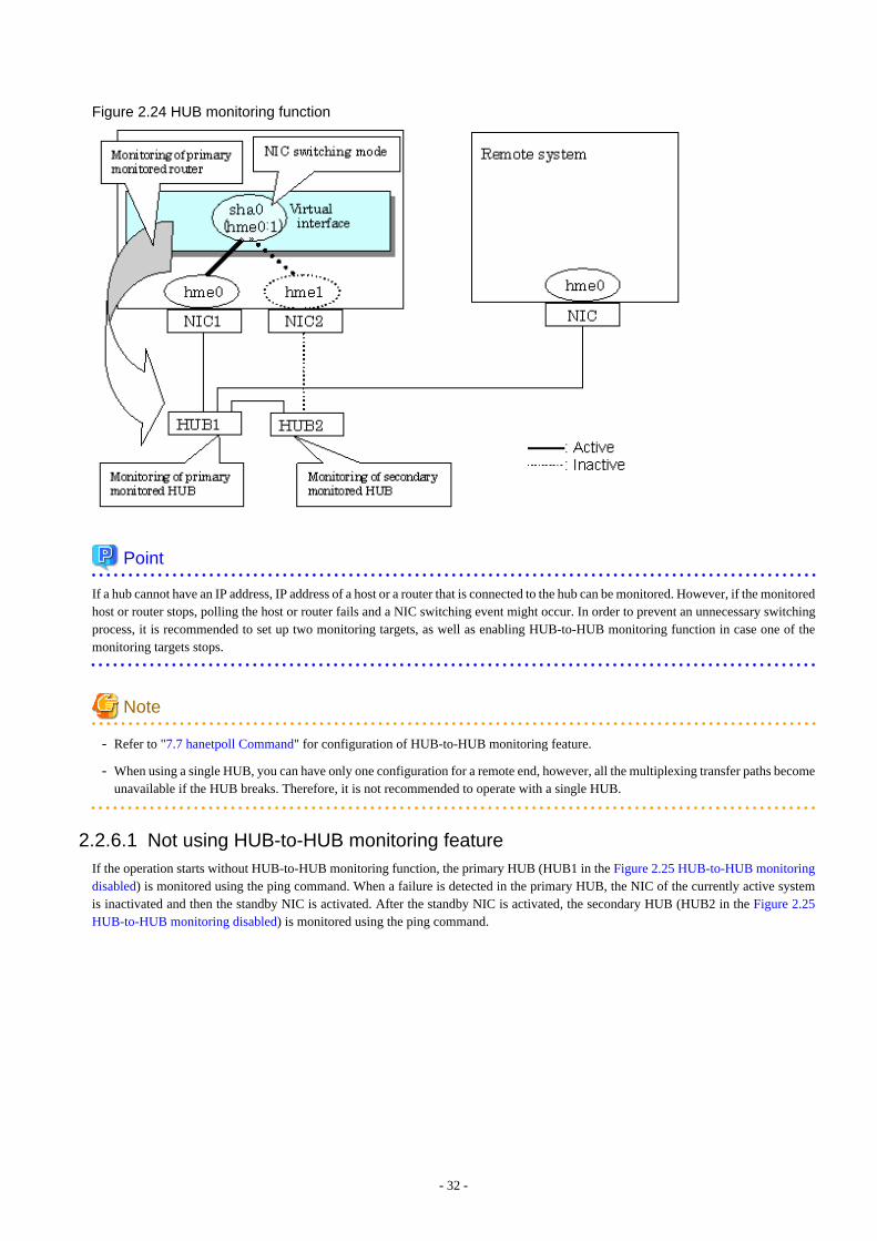
Figure 2.24 HUB monitoring function
Point
If a hub cannot have an IP address, IP address of a host or a router that is connected to the hub can be monitored. However, if the monitoredhost or router stops, polling the host or router fails and a NIC switching event might occur. In order to prevent an unnecessary switchingprocess, it is recommended to set up two monitoring targets, as well as enabling HUB-to-HUB monitoring function in case one of themonitoring targets stops.
Note
- Refer to "7.7 hanetpoll Command" for configuration of HUB-to-HUB monitoring feature.
- When using a single HUB, you can have only one configuration for a remote end, however, all the multiplexing transfer paths becomeunavailable if the HUB breaks. Therefore, it is not recommended to operate with a single HUB.
2.2.6.1 Not using HUB-to-HUB monitoring featureIf the operation starts without HUB-to-HUB monitoring function, the primary HUB (HUB1 in the Figure 2.25 HUB-to-HUB monitoringdisabled) is monitored using the ping command. When a failure is detected in the primary HUB, the NIC of the currently active systemis inactivated and then the standby NIC is activated. After the standby NIC is activated, the secondary HUB (HUB2 in the Figure 2.25HUB-to-HUB monitoring disabled) is monitored using the ping command.
- 32 -
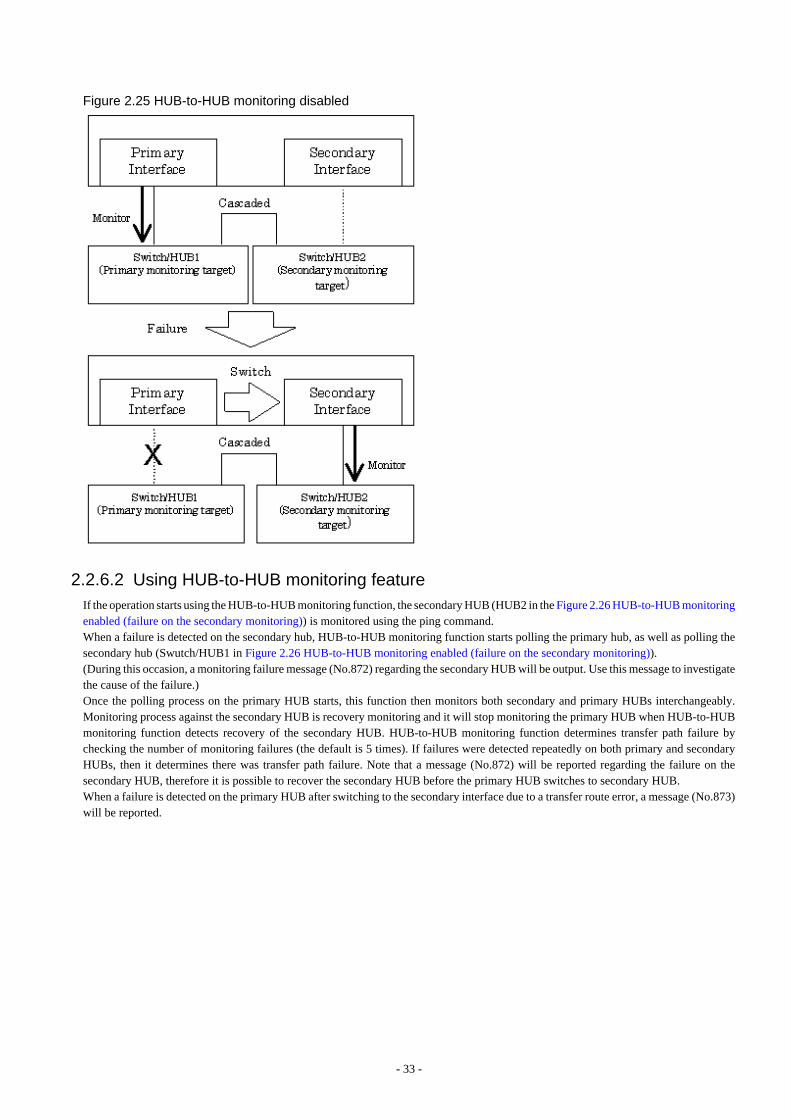
Figure 2.25 HUB-to-HUB monitoring disabled
2.2.6.2 Using HUB-to-HUB monitoring featureIf the operation starts using the HUB-to-HUB monitoring function, the secondary HUB (HUB2 in the Figure 2.26 HUB-to-HUB monitoringenabled (failure on the secondary monitoring)) is monitored using the ping command.When a failure is detected on the secondary hub, HUB-to-HUB monitoring function starts polling the primary hub, as well as polling thesecondary hub (Swutch/HUB1 in Figure 2.26 HUB-to-HUB monitoring enabled (failure on the secondary monitoring)).(During this occasion, a monitoring failure message (No.872) regarding the secondary HUB will be output. Use this message to investigatethe cause of the failure.)Once the polling process on the primary HUB starts, this function then monitors both secondary and primary HUBs interchangeably.Monitoring process against the secondary HUB is recovery monitoring and it will stop monitoring the primary HUB when HUB-to-HUBmonitoring function detects recovery of the secondary HUB. HUB-to-HUB monitoring function determines transfer path failure bychecking the number of monitoring failures (the default is 5 times). If failures were detected repeatedly on both primary and secondaryHUBs, then it determines there was transfer path failure. Note that a message (No.872) will be reported regarding the failure on thesecondary HUB, therefore it is possible to recover the secondary HUB before the primary HUB switches to secondary HUB.When a failure is detected on the primary HUB after switching to the secondary interface due to a transfer route error, a message (No.873)will be reported.
- 33 -
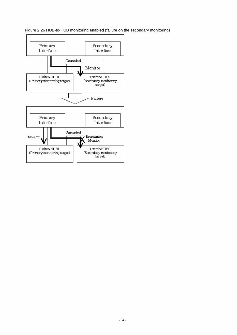
Figure 2.26 HUB-to-HUB monitoring enabled (failure on the secondary monitoring)
- 34 -
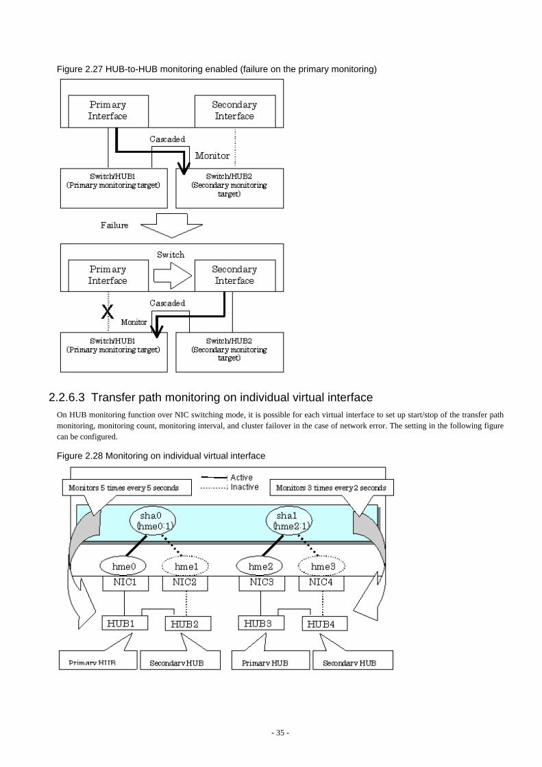
Figure 2.27 HUB-to-HUB monitoring enabled (failure on the primary monitoring)
2.2.6.3 Transfer path monitoring on individual virtual interfaceOn HUB monitoring function over NIC switching mode, it is possible for each virtual interface to set up start/stop of the transfer pathmonitoring, monitoring count, monitoring interval, and cluster failover in the case of network error. The setting in the following figurecan be configured.
Figure 2.28 Monitoring on individual virtual interface
- 35 -
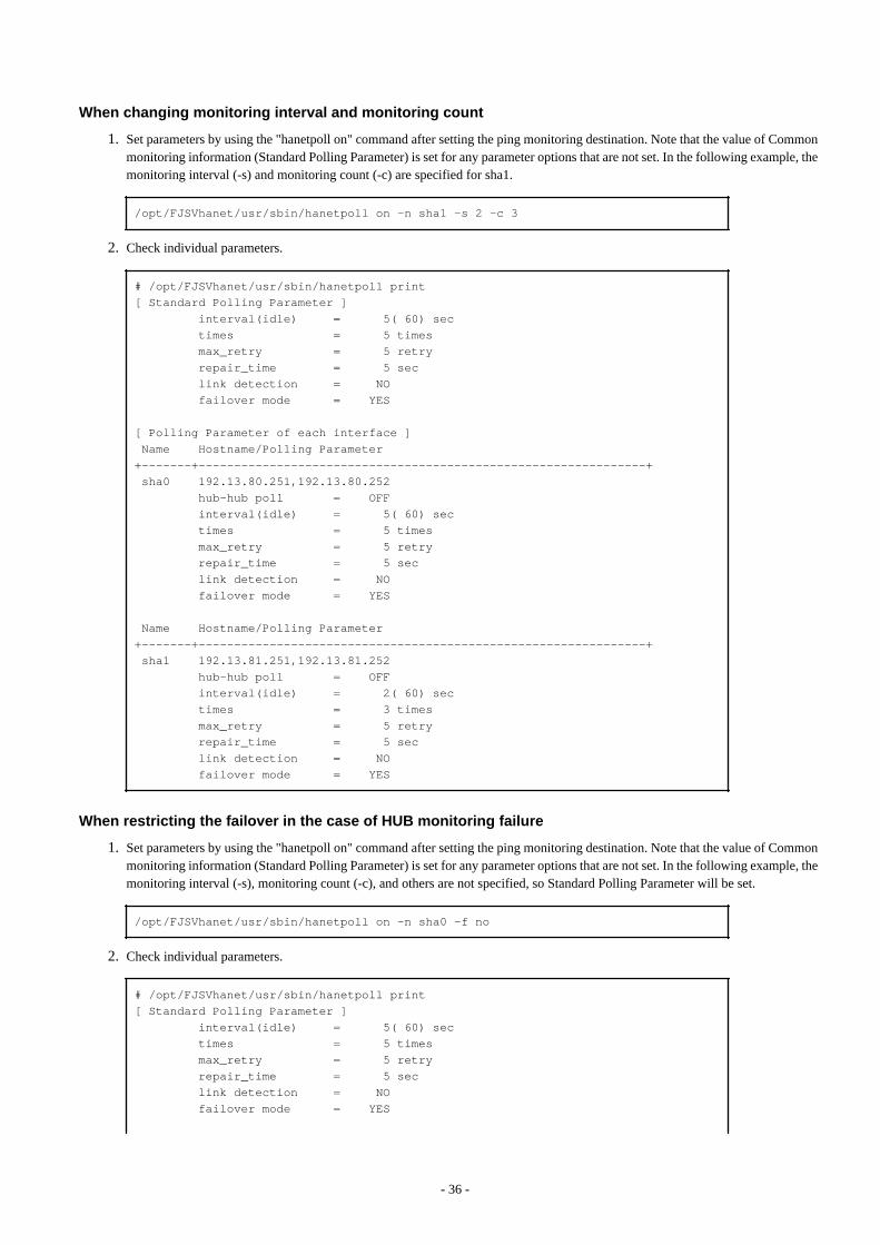
When changing monitoring interval and monitoring count
1. Set parameters by using the "hanetpoll on" command after setting the ping monitoring destination. Note that the value of Commonmonitoring information (Standard Polling Parameter) is set for any parameter options that are not set. In the following example, themonitoring interval (-s) and monitoring count (-c) are specified for sha1.
/opt/FJSVhanet/usr/sbin/hanetpoll on -n sha1 -s 2 -c 3
2. Check individual parameters.
# /opt/FJSVhanet/usr/sbin/hanetpoll print[ Standard Polling Parameter ] interval(idle) = 5( 60) sec times = 5 times max_retry = 5 retry repair_time = 5 sec link detection = NO failover mode = YES
[ Polling Parameter of each interface ] Name Hostname/Polling Parameter+-------+---------------------------------------------------------------+ sha0 192.13.80.251,192.13.80.252 hub-hub poll = OFF interval(idle) = 5( 60) sec times = 5 times max_retry = 5 retry repair_time = 5 sec link detection = NO failover mode = YES
Name Hostname/Polling Parameter+-------+---------------------------------------------------------------+ sha1 192.13.81.251,192.13.81.252 hub-hub poll = OFF interval(idle) = 2( 60) sec times = 3 times max_retry = 5 retry repair_time = 5 sec link detection = NO failover mode = YES
When restricting the failover in the case of HUB monitoring failure
1. Set parameters by using the "hanetpoll on" command after setting the ping monitoring destination. Note that the value of Commonmonitoring information (Standard Polling Parameter) is set for any parameter options that are not set. In the following example, themonitoring interval (-s), monitoring count (-c), and others are not specified, so Standard Polling Parameter will be set.
/opt/FJSVhanet/usr/sbin/hanetpoll on -n sha0 -f no
2. Check individual parameters.
# /opt/FJSVhanet/usr/sbin/hanetpoll print[ Standard Polling Parameter ] interval(idle) = 5( 60) sec times = 5 times max_retry = 5 retry repair_time = 5 sec link detection = NO failover mode = YES
- 36 -
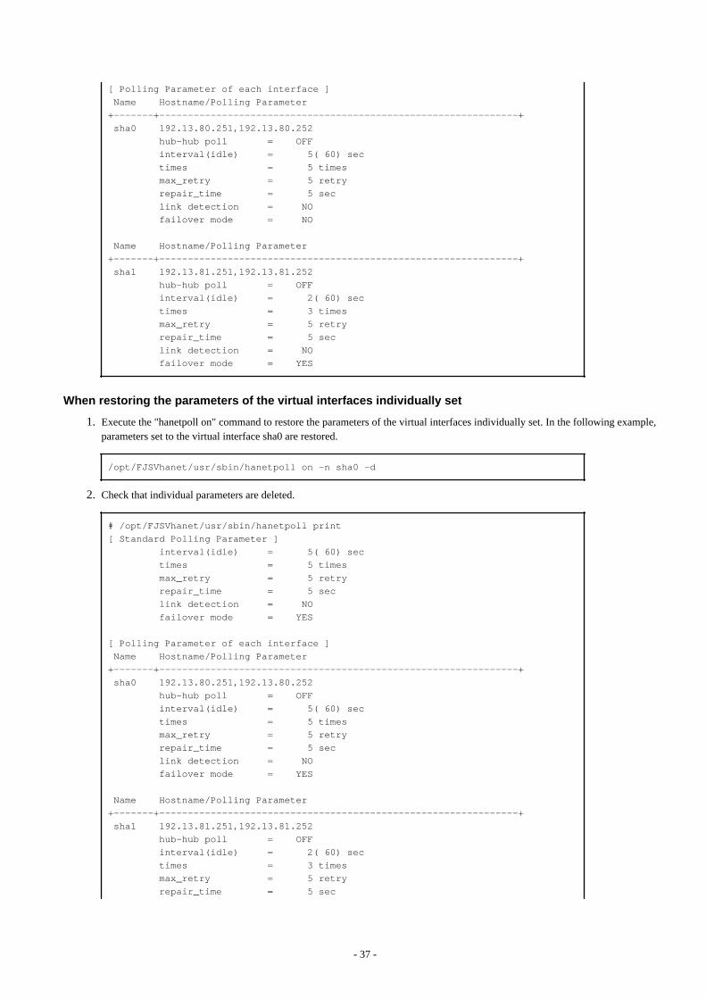
[ Polling Parameter of each interface ] Name Hostname/Polling Parameter+-------+---------------------------------------------------------------+ sha0 192.13.80.251,192.13.80.252 hub-hub poll = OFF interval(idle) = 5( 60) sec times = 5 times max_retry = 5 retry repair_time = 5 sec link detection = NO failover mode = NO
Name Hostname/Polling Parameter+-------+---------------------------------------------------------------+ sha1 192.13.81.251,192.13.81.252 hub-hub poll = OFF interval(idle) = 2( 60) sec times = 3 times max_retry = 5 retry repair_time = 5 sec link detection = NO failover mode = YES
When restoring the parameters of the virtual interfaces individually set
1. Execute the "hanetpoll on" command to restore the parameters of the virtual interfaces individually set. In the following example,parameters set to the virtual interface sha0 are restored.
/opt/FJSVhanet/usr/sbin/hanetpoll on -n sha0 -d
2. Check that individual parameters are deleted.
# /opt/FJSVhanet/usr/sbin/hanetpoll print[ Standard Polling Parameter ] interval(idle) = 5( 60) sec times = 5 times max_retry = 5 retry repair_time = 5 sec link detection = NO failover mode = YES
[ Polling Parameter of each interface ] Name Hostname/Polling Parameter+-------+---------------------------------------------------------------+ sha0 192.13.80.251,192.13.80.252 hub-hub poll = OFF interval(idle) = 5( 60) sec times = 5 times max_retry = 5 retry repair_time = 5 sec link detection = NO failover mode = YES
Name Hostname/Polling Parameter+-------+---------------------------------------------------------------+ sha1 192.13.81.251,192.13.81.252 hub-hub poll = OFF interval(idle) = 2( 60) sec times = 3 times max_retry = 5 retry repair_time = 5 sec
- 37 -
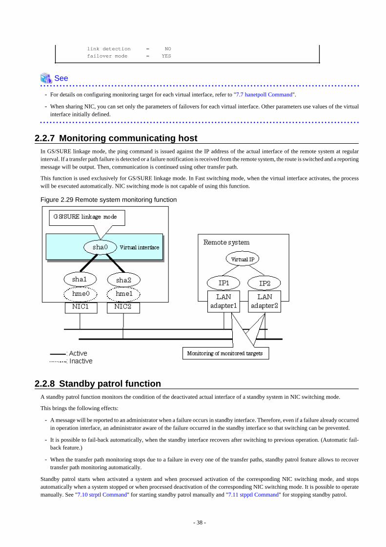
link detection = NO failover mode = YES
See
- For details on configuring monitoring target for each virtual interface, refer to "7.7 hanetpoll Command".
- When sharing NIC, you can set only the parameters of failovers for each virtual interface. Other parameters use values of the virtualinterface initially defined.
2.2.7 Monitoring communicating hostIn GS/SURE linkage mode, the ping command is issued against the IP address of the actual interface of the remote system at regularinterval. If a transfer path failure is detected or a failure notification is received from the remote system, the route is switched and a reportingmessage will be output. Then, communication is continued using other transfer path.
This function is used exclusively for GS/SURE linkage mode. In Fast switching mode, when the virtual interface activates, the processwill be executed automatically. NIC switching mode is not capable of using this function.
Figure 2.29 Remote system monitoring function
2.2.8 Standby patrol functionA standby patrol function monitors the condition of the deactivated actual interface of a standby system in NIC switching mode.
This brings the following effects:
- A message will be reported to an administrator when a failure occurs in standby interface. Therefore, even if a failure already occurredin operation interface, an administrator aware of the failure occurred in the standby interface so that switching can be prevented.
- It is possible to fail-back automatically, when the standby interface recovers after switching to previous operation. (Automatic fail-back feature.)
- When the transfer path monitoring stops due to a failure in every one of the transfer paths, standby patrol feature allows to recovertransfer path monitoring automatically.
Standby patrol starts when activated a system and when processed activation of the corresponding NIC switching mode, and stopsautomatically when a system stopped or when processed deactivation of the corresponding NIC switching mode. It is possible to operatemanually. See "7.10 strptl Command" for starting standby patrol manually and "7.11 stpptl Command" for stopping standby patrol.
- 38 -
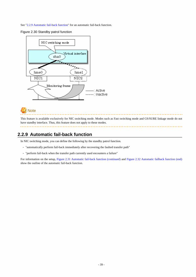
See "2.2.9 Automatic fail-back function" for an automatic fail-back function.
Figure 2.30 Standby patrol function
Note
This feature is available exclusively for NIC switching mode. Modes such as Fast switching mode and GS/SURE linkage mode do nothave standby interface. Thus, this feature does not apply to these modes.
2.2.9 Automatic fail-back functionIn NIC switching mode, you can define the following by the standby patrol function.
- "automatically perform fail-back immediately after recovering the faulted transfer path"
- "perform fail-back when the transfer path currently used encounters a failure"
For information on the setup, Figure 2.31 Automatic fail-back function (continued) and Figure 2.32 Automatic failback function (end)show the outline of the automatic fail-back function.
- 39 -
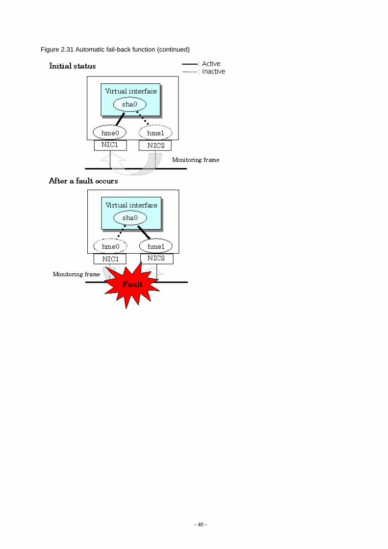
Figure 2.31 Automatic fail-back function (continued)
- 40 -
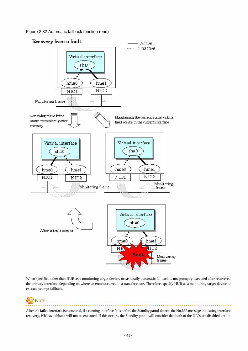
Figure 2.32 Automatic failback function (end)
When specified other than HUB as a monitoring target device, occasionally automatic failback is not promptly executed after recoveredthe primary interface, depending on where an error occurred in a transfer route. Therefore, specify HUB as a monitoring target device toexecute prompt failback.
Note
After the failed interface is recovered, if a running interface fails before the Standby patrol detects the No.885 message indicating interfacerecovery, NIC switchback will not be executed. If this occurs, the Standby patrol will consider that both of the NICs are disabled until it
- 41 -
detects the failed interface recovery. Recover the interface referring to "4.6.2 Recovery procedure from line failure in NIC switchingmode".
2.2.10 Dynamically adding/deleting/switching physical interfaceIn Fast switching mode and GS/SURE linkage mode (the operation mode is "c"), it is possible to add/delete bundled physical interfaceswith a virtual interface kept activated (dynamic). The hanetnic command adds/deletes dynamically. See "7.9 hanetnic Command" for thedetail.Figure 2.33 Dynamic adding/deleting function of physical interfaces used shows the outline of actions when executed a command to add/delete the physical interface dynamically.Dynamic addition/deletion commands of physical interfaces have two modes below.
Temporal dynamic addition/deletion:
Operates physical interfaces to bundle without editing a configuration information file. Therefore, it automatically returns to the originalstate by operating a machine to reboot, etc. It is not possible to add other than the physical interface that was deleted by this modewhen adding dynamically.
Permanent dynamic addition/deletion:
Edits a configuration information file. Therefore, changes are reflected even after operated a machine to reboot, etc.
- 42 -
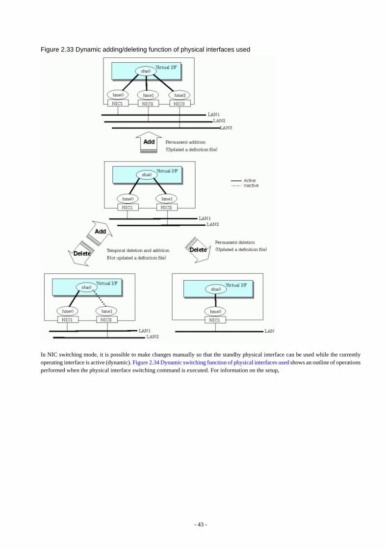
Figure 2.33 Dynamic adding/deleting function of physical interfaces used
In NIC switching mode, it is possible to make changes manually so that the standby physical interface can be used while the currentlyoperating interface is active (dynamic). Figure 2.34 Dynamic switching function of physical interfaces used shows an outline of operationsperformed when the physical interface switching command is executed. For information on the setup,
- 43 -
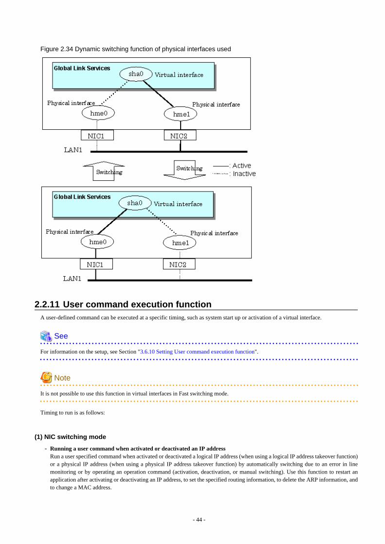
Figure 2.34 Dynamic switching function of physical interfaces used
2.2.11 User command execution functionA user-defined command can be executed at a specific timing, such as system start up or activation of a virtual interface.
See
For information on the setup, see Section "3.6.10 Setting User command execution function".
Note
It is not possible to use this function in virtual interfaces in Fast switching mode.
Timing to run is as follows:
(1) NIC switching mode
- Running a user command when activated or deactivated an IP addressRun a user specified command when activated or deactivated a logical IP address (when using a logical IP address takeover function)or a physical IP address (when using a physical IP address takeover function) by automatically switching due to an error in linemonitoring or by operating an operation command (activation, deactivation, or manual switching). Use this function to restart anapplication after activating or deactivating an IP address, to set the specified routing information, to delete the ARP information, andto change a MAC address.
- 44 -
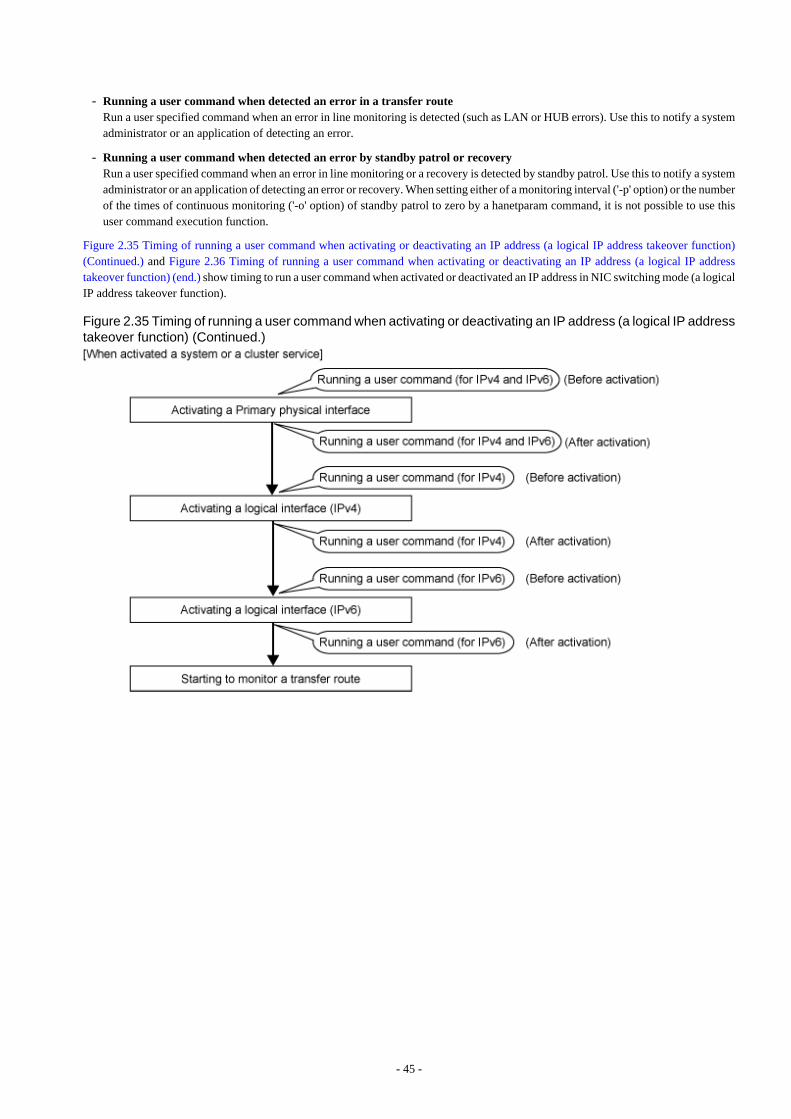
- Running a user command when detected an error in a transfer routeRun a user specified command when an error in line monitoring is detected (such as LAN or HUB errors). Use this to notify a systemadministrator or an application of detecting an error.
- Running a user command when detected an error by standby patrol or recoveryRun a user specified command when an error in line monitoring or a recovery is detected by standby patrol. Use this to notify a systemadministrator or an application of detecting an error or recovery. When setting either of a monitoring interval ('-p' option) or the numberof the times of continuous monitoring ('-o' option) of standby patrol to zero by a hanetparam command, it is not possible to use thisuser command execution function.
Figure 2.35 Timing of running a user command when activating or deactivating an IP address (a logical IP address takeover function)(Continued.) and Figure 2.36 Timing of running a user command when activating or deactivating an IP address (a logical IP addresstakeover function) (end.) show timing to run a user command when activated or deactivated an IP address in NIC switching mode (a logicalIP address takeover function).
Figure 2.35 Timing of running a user command when activating or deactivating an IP address (a logical IP addresstakeover function) (Continued.)
- 45 -
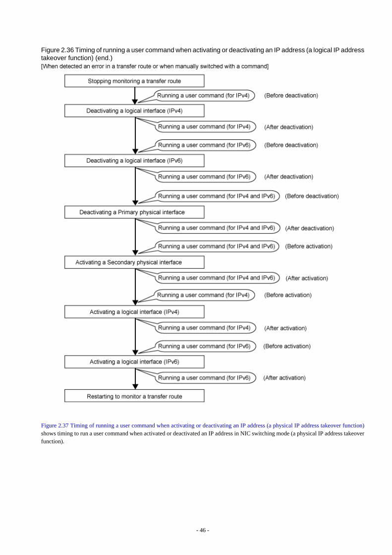
Figure 2.36 Timing of running a user command when activating or deactivating an IP address (a logical IP addresstakeover function) (end.)
Figure 2.37 Timing of running a user command when activating or deactivating an IP address (a physical IP address takeover function)shows timing to run a user command when activated or deactivated an IP address in NIC switching mode (a physical IP address takeoverfunction).
- 46 -
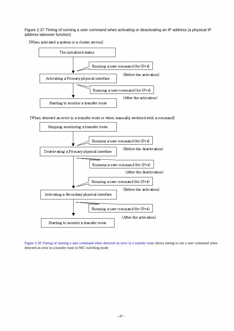
Figure 2.37 Timing of running a user command when activating or deactivating an IP address (a physical IPaddress takeover function)
Figure 2.38 Timing of running a user command when detected an error in a transfer route shows timing to run a user command whendetected an error in a transfer route in NIC switching mode
- 47 -
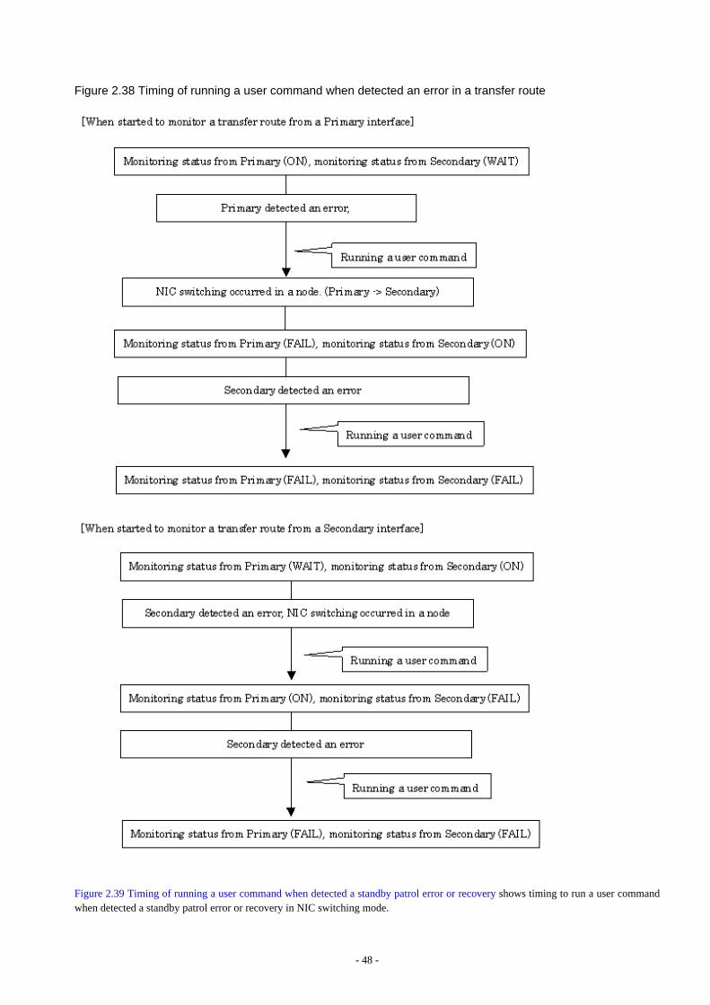
Figure 2.38 Timing of running a user command when detected an error in a transfer route
Figure 2.39 Timing of running a user command when detected a standby patrol error or recovery shows timing to run a user commandwhen detected a standby patrol error or recovery in NIC switching mode.
- 48 -
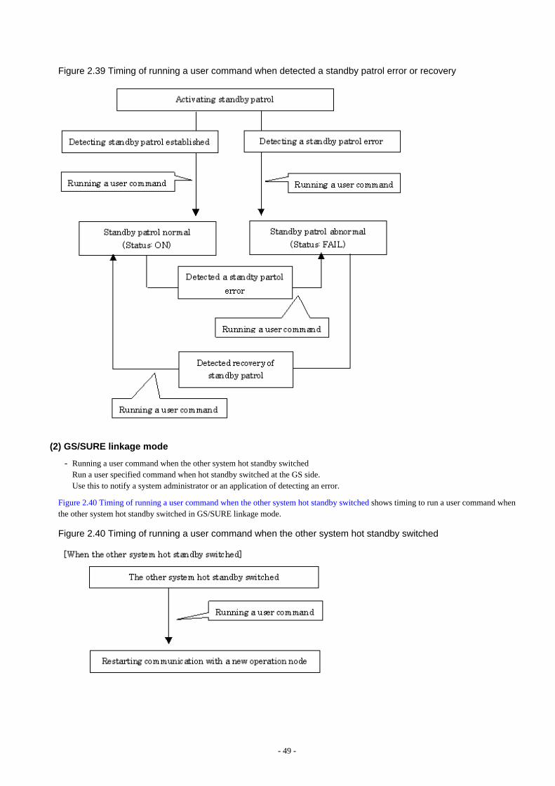
Figure 2.39 Timing of running a user command when detected a standby patrol error or recovery
(2) GS/SURE linkage mode
- Running a user command when the other system hot standby switchedRun a user specified command when hot standby switched at the GS side.Use this to notify a system administrator or an application of detecting an error.
Figure 2.40 Timing of running a user command when the other system hot standby switched shows timing to run a user command whenthe other system hot standby switched in GS/SURE linkage mode.
Figure 2.40 Timing of running a user command when the other system hot standby switched
- 49 -
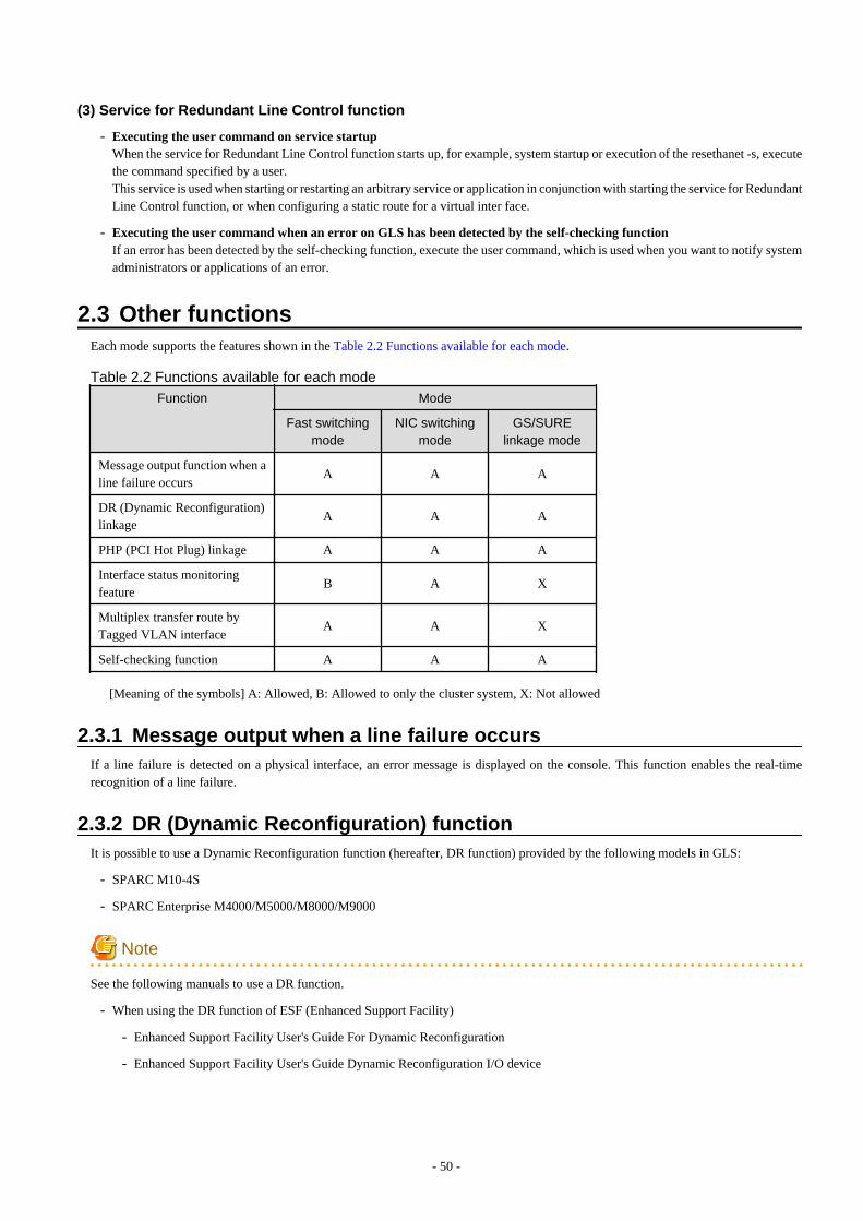
(3) Service for Redundant Line Control function
- Executing the user command on service startupWhen the service for Redundant Line Control function starts up, for example, system startup or execution of the resethanet -s, executethe command specified by a user.This service is used when starting or restarting an arbitrary service or application in conjunction with starting the service for RedundantLine Control function, or when configuring a static route for a virtual inter face.
- Executing the user command when an error on GLS has been detected by the self-checking functionIf an error has been detected by the self-checking function, execute the user command, which is used when you want to notify systemadministrators or applications of an error.
2.3 Other functionsEach mode supports the features shown in the Table 2.2 Functions available for each mode.
Table 2.2 Functions available for each mode
Function Mode
Fast switchingmode
NIC switchingmode
GS/SURElinkage mode
Message output function when aline failure occurs
A A A
DR (Dynamic Reconfiguration)linkage
A A A
PHP (PCI Hot Plug) linkage A A A
Interface status monitoringfeature
B A X
Multiplex transfer route byTagged VLAN interface
A A X
Self-checking function A A A
[Meaning of the symbols] A: Allowed, B: Allowed to only the cluster system, X: Not allowed
2.3.1 Message output when a line failure occursIf a line failure is detected on a physical interface, an error message is displayed on the console. This function enables the real-timerecognition of a line failure.
2.3.2 DR (Dynamic Reconfiguration) functionIt is possible to use a Dynamic Reconfiguration function (hereafter, DR function) provided by the following models in GLS:
- SPARC M10-4S
- SPARC Enterprise M4000/M5000/M8000/M9000
Note
See the following manuals to use a DR function.
- When using the DR function of ESF (Enhanced Support Facility)
- Enhanced Support Facility User's Guide For Dynamic Reconfiguration
- Enhanced Support Facility User's Guide Dynamic Reconfiguration I/O device
- 50 -
- When using the DR function of XSCF (eXtended System Control Facility)
- For SPARC M10-4S
- Fujitsu M10/SPARC M10 Systems Domain Configuration Guide
- Fujitsu M10/SPARC M10 Systems XSCF Reference Manual
- For SPARC Enterprise M4000/M5000/M8000/M9000
- Dynamic Reconfiguration (DR) User's Guide
- XSCF User's Guide
2.3.2.1 DR (Dynamic Reconfiguration) linkage functionA DR connection script, which enables automatic disconnection or embedding of an NIC in a redundant configuration, is provided to usethe DR function of ESF in a Redundant Line Control function. When a DR connection script is invoked by executing a DR command, itdisconnects or connects a virtual interface (sha0, etc.) and an actual interface (hme0, etc.). This makes it possible to execute a DR functionwithout realizing an interface, a function, and a DR connection script used in various modes. "Figure 2.41 Flow of exchanging systemboards (SB) using a DR function" shows a flow of exchanging system boards (SB) using a DR function.
- 51 -
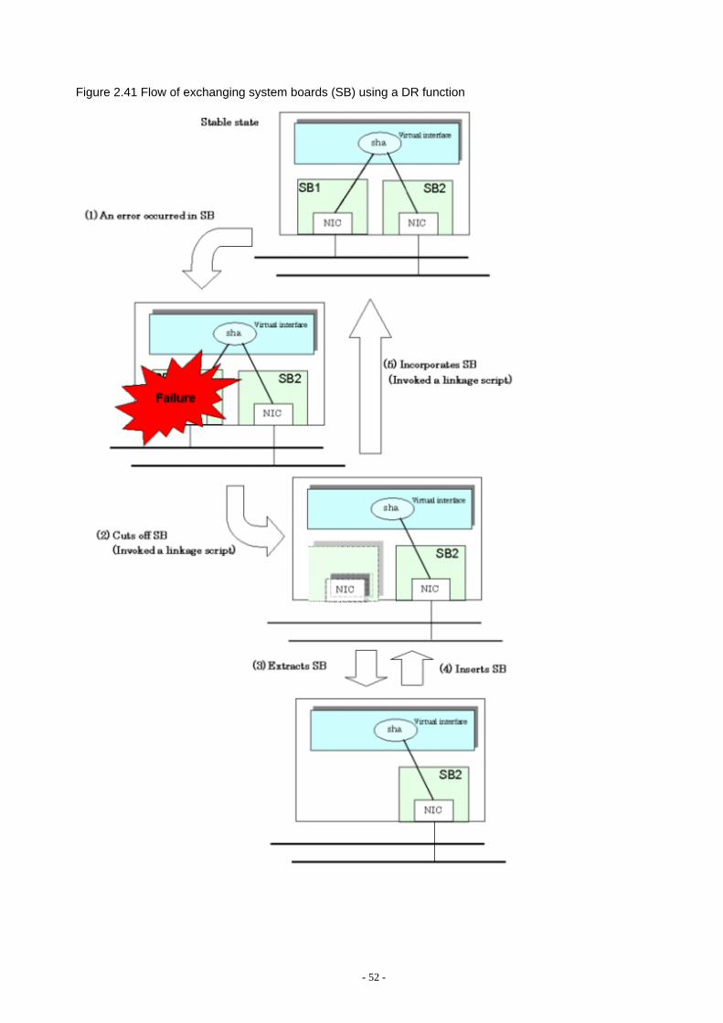
Figure 2.41 Flow of exchanging system boards (SB) using a DR function
- 52 -

Note
The DR linkage script does not support the disconnecting/embedding of an NIC under a redundant virtual interface comprised of an IPv6virtual interface and a tagged VLAN Interface. If disconnecting the system board with a DR command, manually disconnect the NIC builtinto the system board from the multiplex configuration first. Also, after performing the system board embedding, perform embedding tothe multiplex configuration.
2.3.2.2 DR function of XSCFWhen using DR function of XSCF, execute the "hanetnic delete" command to delete NIC from the redundant configuration before detachingthe system board. Similarly, after attaching the system board, execute the "hanetnic add" command to add NIC to the redundantconfiguration. The following shows the flow chart of replacing the system board (SB) by the DR function of XSCF.
- 53 -
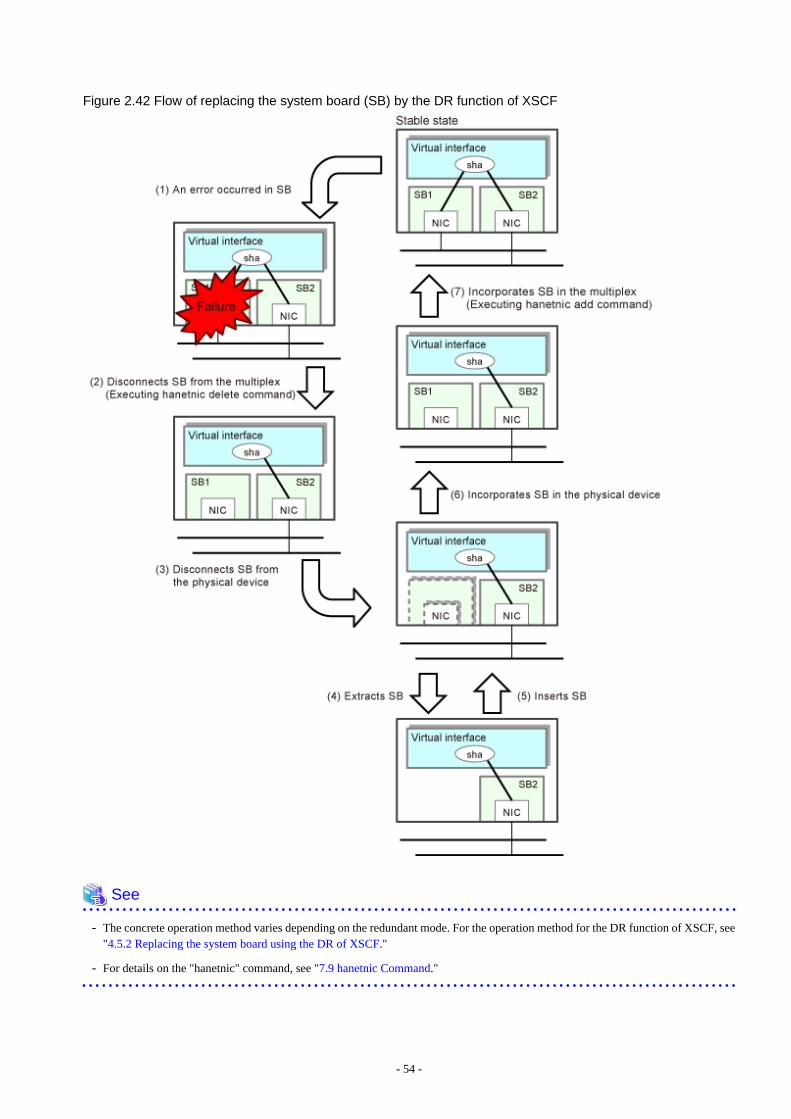
Figure 2.42 Flow of replacing the system board (SB) by the DR function of XSCF
See
- The concrete operation method varies depending on the redundant mode. For the operation method for the DR function of XSCF, see"4.5.2 Replacing the system board using the DR of XSCF."
- For details on the "hanetnic" command, see "7.9 hanetnic Command."
- 54 -
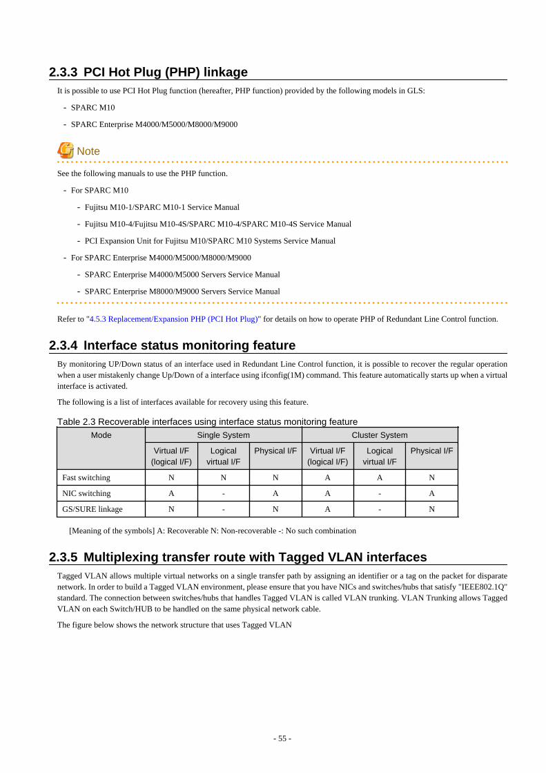
2.3.3 PCI Hot Plug (PHP) linkageIt is possible to use PCI Hot Plug function (hereafter, PHP function) provided by the following models in GLS:
- SPARC M10
- SPARC Enterprise M4000/M5000/M8000/M9000
Note
See the following manuals to use the PHP function.
- For SPARC M10
- Fujitsu M10-1/SPARC M10-1 Service Manual
- Fujitsu M10-4/Fujitsu M10-4S/SPARC M10-4/SPARC M10-4S Service Manual
- PCI Expansion Unit for Fujitsu M10/SPARC M10 Systems Service Manual
- For SPARC Enterprise M4000/M5000/M8000/M9000
- SPARC Enterprise M4000/M5000 Servers Service Manual
- SPARC Enterprise M8000/M9000 Servers Service Manual
Refer to "4.5.3 Replacement/Expansion PHP (PCI Hot Plug)" for details on how to operate PHP of Redundant Line Control function.
2.3.4 Interface status monitoring featureBy monitoring UP/Down status of an interface used in Redundant Line Control function, it is possible to recover the regular operationwhen a user mistakenly change Up/Down of a interface using ifconfig(1M) command. This feature automatically starts up when a virtualinterface is activated.
The following is a list of interfaces available for recovery using this feature.
Table 2.3 Recoverable interfaces using interface status monitoring feature
Mode Single System Cluster System
Virtual I/F(logical I/F)
Logicalvirtual I/F
Physical I/F Virtual I/F(logical I/F)
Logicalvirtual I/F
Physical I/F
Fast switching N N N A A N
NIC switching A - A A - A
GS/SURE linkage N - N A - N
[Meaning of the symbols] A: Recoverable N: Non-recoverable -: No such combination
2.3.5 Multiplexing transfer route with Tagged VLAN interfacesTagged VLAN allows multiple virtual networks on a single transfer path by assigning an identifier or a tag on the packet for disparatenetwork. In order to build a Tagged VLAN environment, please ensure that you have NICs and switches/hubs that satisfy "IEEE802.1Q"standard. The connection between switches/hubs that handles Tagged VLAN is called VLAN trunking. VLAN Trunking allows TaggedVLAN on each Switch/HUB to be handled on the same physical network cable.
The figure below shows the network structure that uses Tagged VLAN
- 55 -
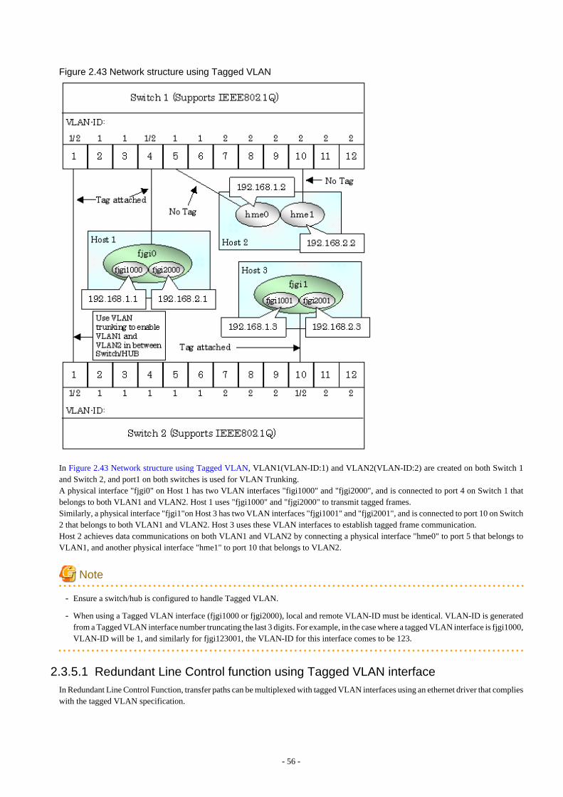
Figure 2.43 Network structure using Tagged VLAN
In Figure 2.43 Network structure using Tagged VLAN, VLAN1(VLAN-ID:1) and VLAN2(VLAN-ID:2) are created on both Switch 1and Switch 2, and port1 on both switches is used for VLAN Trunking.A physical interface "fjgi0" on Host 1 has two VLAN interfaces "figi1000" and "fjgi2000", and is connected to port 4 on Switch 1 thatbelongs to both VLAN1 and VLAN2. Host 1 uses "fjgi1000" and "fjgi2000" to transmit tagged frames.Similarly, a physical interface "fjgi1"on Host 3 has two VLAN interfaces "fjgi1001" and "fjgi2001", and is connected to port 10 on Switch2 that belongs to both VLAN1 and VLAN2. Host 3 uses these VLAN interfaces to establish tagged frame communication.Host 2 achieves data communications on both VLAN1 and VLAN2 by connecting a physical interface "hme0" to port 5 that belongs toVLAN1, and another physical interface "hme1" to port 10 that belongs to VLAN2.
Note
- Ensure a switch/hub is configured to handle Tagged VLAN.
- When using a Tagged VLAN interface (fjgi1000 or fjgi2000), local and remote VLAN-ID must be identical. VLAN-ID is generatedfrom a Tagged VLAN interface number truncating the last 3 digits. For example, in the case where a tagged VLAN interface is fjgi1000,VLAN-ID will be 1, and similarly for fjgi123001, the VLAN-ID for this interface comes to be 123.
2.3.5.1 Redundant Line Control function using Tagged VLAN interfaceIn Redundant Line Control Function, transfer paths can be multiplexed with tagged VLAN interfaces using an ethernet driver that complieswith the tagged VLAN specification.
- 56 -
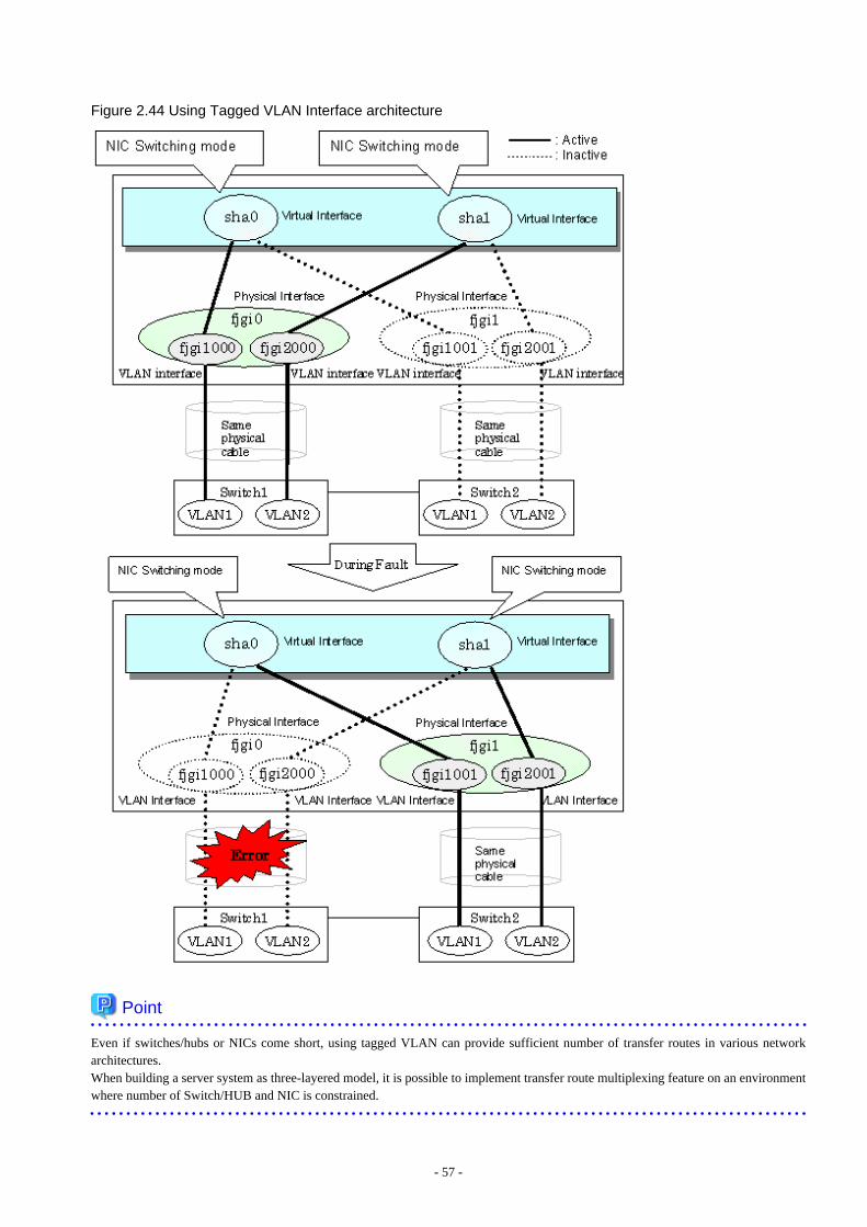
Figure 2.44 Using Tagged VLAN Interface architecture
Point
Even if switches/hubs or NICs come short, using tagged VLAN can provide sufficient number of transfer routes in various networkarchitectures.When building a server system as three-layered model, it is possible to implement transfer route multiplexing feature on an environmentwhere number of Switch/HUB and NIC is constrained.
- 57 -
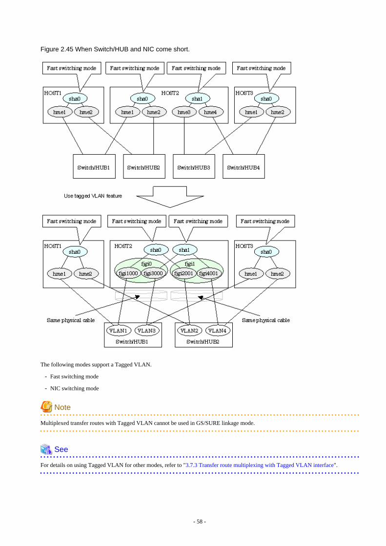
Figure 2.45 When Switch/HUB and NIC come short.
The following modes support a Tagged VLAN.
- Fast switching mode
- NIC switching mode
Note
Multiplexed transfer routes with Tagged VLAN cannot be used in GS/SURE linkage mode.
See
For details on using Tagged VLAN for other modes, refer to "3.7.3 Transfer route multiplexing with Tagged VLAN interface".
- 58 -
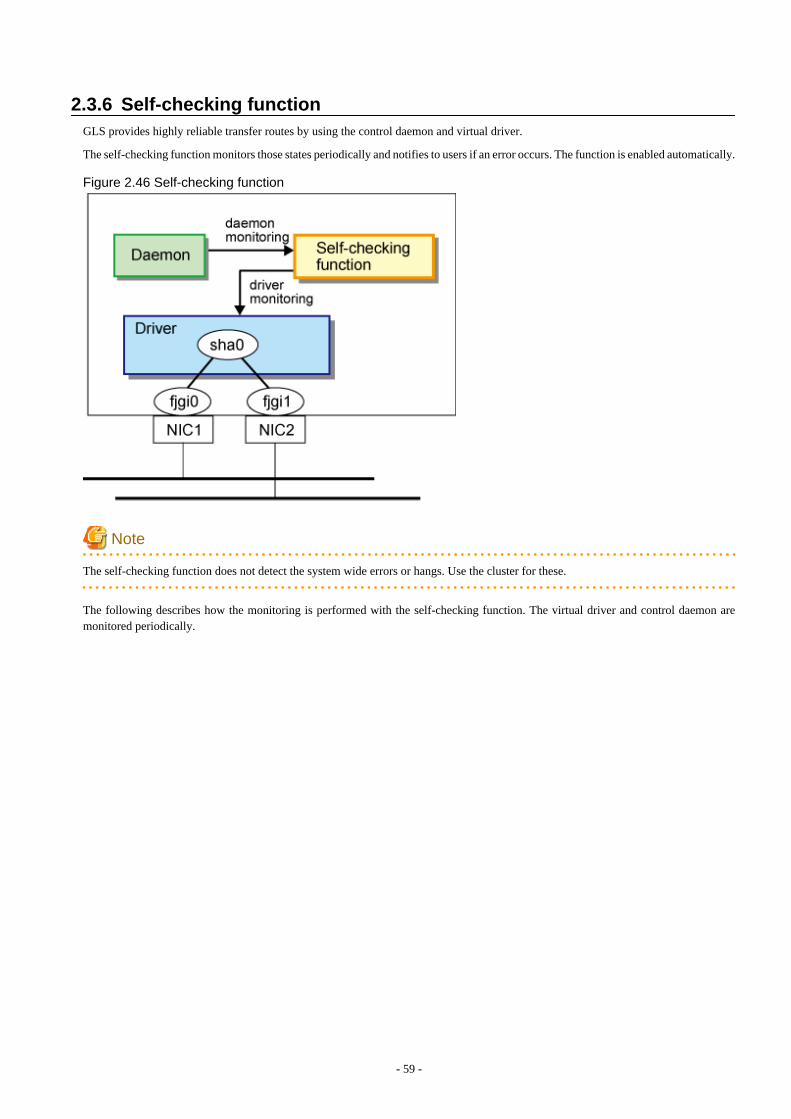
2.3.6 Self-checking functionGLS provides highly reliable transfer routes by using the control daemon and virtual driver.
The self-checking function monitors those states periodically and notifies to users if an error occurs. The function is enabled automatically.
Figure 2.46 Self-checking function
Note
The self-checking function does not detect the system wide errors or hangs. Use the cluster for these.
The following describes how the monitoring is performed with the self-checking function. The virtual driver and control daemon aremonitored periodically.
- 59 -
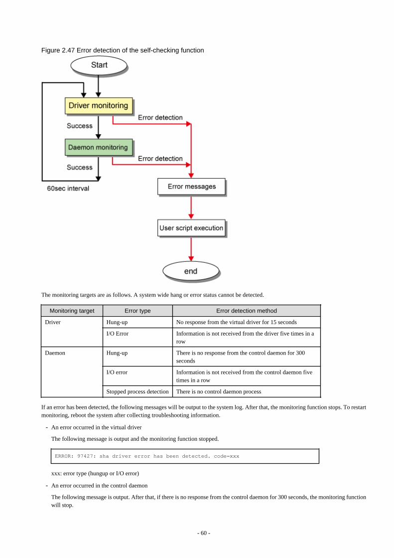
Figure 2.47 Error detection of the self-checking function
The monitoring targets are as follows. A system wide hang or error status cannot be detected.
Monitoring target Error type Error detection method
Driver Hung-up No response from the virtual driver for 15 seconds
I/O Error Information is not received from the driver five times in arow
Daemon Hung-up There is no response from the control daemon for 300seconds
I/O error Information is not received from the control daemon fivetimes in a row
Stopped process detection There is no control daemon process
If an error has been detected, the following messages will be output to the system log. After that, the monitoring function stops. To restartmonitoring, reboot the system after collecting troubleshooting information.
- An error occurred in the virtual driver
The following message is output and the monitoring function stopped.
ERROR: 97427: sha driver error has been detected. code=xxx
xxx: error type (hungup or I/O error)
- An error occurred in the control daemon
The following message is output. After that, if there is no response from the control daemon for 300 seconds, the monitoring functionwill stop.
- 60 -
ERROR: 97627: hanetctld error has been detected. code=xxx
xxx: error type (hungup, I/O error, or stopped process)
However, if the control daemon recovered, the following message will be output and the monitoring will continue.
ERROR: 97727: hanetctld recovery has been detected.
Note that placing a script in the following location allows the script to be executed when an error is detected. For more details, see "3.6.10Setting User command execution function."
/etc/opt/FJSVhanet/script/system/monitor
Information
Rebooting the system is recommended after the monitoring function stopped.
If a hung-up or an I/O error was detected due to temporary system load, the self-check function can be restored by restarting it as below.
# svcadm restart fjsvhanet-poll
If the self-check function failed to be restarted, collect materials for examination, and then contact field engineers to report the errormessage.
In this case, an error may have been occurred or the system resources may be low. To resolve these problems, reboot the system.
2.4 Notes
2.4.1 General
Notes on setting a configuration:
- The minimum and maximum number of virtual and logical virtual interface can be defined is 1 to 64.
- The number of physical interfaces can be used for redundancy on a single virtual interface is within 1 to 8 for Fast switching and GS/SURE linkage mode. For NIC switching mode, the range is within 1 to 2.
- The number of logical virtual interfaces that can be defined to a single logical virtual interface is within 1 to 63.
- When using the tagged VLAN interface in Solaris 11 environment, do not specify the VLAN link name to create the tagged VLANinterface. Use the automatically generated interface name.
Automatically generated interface name:
"net" + VLAN-ID + instance number (*1)
*1: The instance number is represented by 3-digit number XXX (from 000 to 999).
Example: If VLAN-ID is 12 and the NIC name is net3, the automatically generated VLAN interface name will become "net12003".
- The interface name that is bundled by the virtual interface must be specified within 11 characters.
- If VLAN is not used, an interface name that can be recognized as the VLAN interface name cannot be specified for the interfacebundled by the virtual interface. For example, if an integer followed by "net" is 1000 or larger such as "net12003", this interface namecannot be specified.
- To use all host names and IP addresses used in a Redundant Line Control function, they must be defined in /etc/inet/ipnodes files ofthe local system.
- 61 -
- The system automatically determines the length of MTU for an interface. Nonetheless, it is possible to change the length of MTUusing user command execution function. For changing MTU length, refer to "3.6.10 Setting User command execution function". Notethat the length of MTU cannot be modified in other redundant modes.
- The IPMP virtual interface (ipmpX) cannot be made redundant.
Notes on the operation:
- It is not possible to use a multicast IP address in a Redundant Line Control function.
- Do not execute a DR linkage function in a machine that runs the cluster operation.
- Do not operate physical interfaces that a virtual interface bundles with an ifconfig command.
- GLS does not support Verified Boot.
- The following warning messages may be output to the syslog. However, these messages do not disrupt the system configuration orsystem operation. No action is required.
WARNING: Signature verification of module /usr/kernel/drv/sparcv9/rvnet failedWARNING: Signature verification of module /usr/kernel/drv/sparcv9/rvnetcf failedWARNING: Signature verification of module /usr/kernel/drv/sparcv9/sha failed
Notes on applications:
- When an application uses TCP, the data lost when an error occurred in a transfer route is guaranteed by resending from TCP andreaches the other system in the end. Therefore, TCP connection is not disconnected and there is no error in communication. However,it is necessary to set a timer value longer than the time to finish disconnecting/switching a transfer route when an application monitorsa response by such timer. When TCP connection is disconnected by the reason such as incapability to change a timer value, reestablishthe TCP connection and recover the communication.
- The data lost at the time of an error in a transfer route is not guaranteed when an application uses the UDP. It is necessary to executea recovery process such as sending the data by the application itself.
- It is not possible to use DHCP (a server function and a client function) as the application in a Redundant Line Control function.
- When using NTP as an application, it is necessary to activate an IP address that a Redundant Line Control function controls beforeactivating an NTP daemon. No special operation is required when activating a system because a Redundant Line Control function isactivated before an NTP daemon. However, when manually activated an IP address with an operation command or when runningcluster operation, reactivate an NTP daemon after an IP address is activated.
Notes on Solaris Zones:
- If a zone is activated, an interface in the zone cannot be deactivated.If you want to change or delete the redundant line control function settings, it is necessary to stop the zone first.
- For a shared-IP non-global, if a virtual interface does not exist in a zone, the zone cannot be activated.Before starting the zone, activate the virtual interface.
- If the shared-IP zone is started after NIC is switched from the primary interface to the secondary interface in NIC switching mode, itmight take up to 20 seconds to enable communication in the zone.
- For a shared-IP non-global, if the zone is set to use the secondary interface in NIC switching mode, a network interface in the zonewill automatically be switched to the primary interface when a virtual interface is activated.
- An IP address specified for a zone and that for a virtual interface must be different. If the same IP is specified for both, zone startup or virtual interface activation will fail.
2.4.2 Duplicated operation by Fast switching mode- Redundant Line Control function must be operating on each system that performs duplicated operation by Fast switching mode.
- In Fast switching mode, one virtual network is configured to the redundant transfer route. Therefore, a new network number or asubnetwork number to this virtual network is necessary.
- Only one NIC interface is connectable on one network. It is not possible to connect more than one interface on the same network.
- 62 -
- Any combination is possible for redundant NICs. When combined those of different transfer abilities, the communication ability issuppressed by the one of less transfer ability. Therefore, it is recommended to combine the same kind of NICs and to make themredundant.
- In Fast switching mode, a dedicated Ethernet frame is used. Therefore, when operating VLAN (Virtual LAN), occasionally it is notpossible to communicate depending on the setting of VLAN. In such a case, either to stop using VLAN or to change the setting ofVLAN so that it becomes possible to use an optional Ethernet frame.
- The interface created by SR-IOV cannot be used.
2.4.3 Duplicated operation via NIC switching mode- One unit of HUB to be connected in NIC switching mode is sufficient, but communication may not be conducted normally if the HUB
has MAC learning capabilities. In such a case, add a HUB to make a HUB-to-HUB connection and then connect the cable to eachHUB (See "Figure 2.7 System configuration in NIC switching mode" of "2.1.2 NIC switching mode").
- It is not possible to use a standby patrol function when the type of interface to use is "mpnetX (a logical interface of a multipath)".
- Communication with a multicast IP address is executed using a physical interface (normally, hme0) corresponding to a node name(uname -n). When used this interface in NIC switching mode, it is not possible to communicate with a multicast IP address. Thisoccasionally outputs a following WARNING message from in.rdisc when activated a system:in.rdiscd[xxx]: setsockopt(IP_DROP_MEMBERSHIP): Cannot assign requested addressIn this case, either to set /etc/defaultrouter not to activate in.rdisc or reassign a node name to another interface.
- In a standby patrol function of NIC switching mode, a dedicated Ethernet frame is used. Therefore, when operating VLAN (VirtualLAN), occasionally it is not possible to use a standby patrol function depending on the setting of VLAN. In such a case, either to stopa standby patrol function or VLAN, or change the setting of VLAN so that it becomes possible to use an optional Ethernet frame.
- In NIC switching mode, it is necessary to use a hub that can be assigned an IP address in order for the hub to be monitored. If a hubcannot be assigned an IP address, an IP address of a device connected to the hub can be monitored. However, it should be noted thatif the device whose IP address is monitored fails, the failure is regarded as a transfer route failure.
- When using an IPv6 virtual interface with Solaris 10, create an /etc/hostname6.interface file corresponding to a Primary physicalinterface so that an in.ndpd daemon is activated at activating a system. When the in.ndpd daemon is not activated, an IPv6 address isnot configured automatically. When creating a /etc/hostname6.interface file, make it empty without fail.
- When using an IPv6 virtual interface, an in.ndpd daemon is occasionally reactivated not to delay configuring an IPv6 addressautomatically. A message "SIGHUP: restart and reread config file" is output from the in.ndpd daemon following this, but this is notan error.
- To operate ping monitoring over the system that runs firewall, configure the firewall so that ping can pass through the firewall.Otherwise, it fails to operate ping monitoring. The firewall settings must be the same for both of the primary and secondary interfaces.
- When using an IPv6 virtual interface in an environment where the address autoconfiguration with an IPv6 router is not in use, assigna link local address to the monitored IP.
2.4.4 Duplicated operation via GS/SURE linkage mode- In GS/SURE linkage mode, the system uses duplicated paths concurrently but it cannot be expected to improve the throughput.
- Be sure to set a function to monitor the other side to communicate when using GS/SURE linkage mode. See "7.5 hanetobservCommand" as to how to set.
- In GS/SURE mode, data communication with SPARC M10, SPARC Enterprise, PRIMEPOWER, GP7000F, Fujitsu S series, GP-S,PRIMERGY, or PRIMEQUEST is not possible.
- In GS/SURE linkage mode, the route to the virtual IP address of the destination system is recognized by using the RIP protocol. Setthe RIP advertisement on the GS/SURE system (destination system). In this mode, RIPv1 is supported.
- In GS/SURE linkage mode, communication with up to four hosts is possible. Communication with the fifth host or later is not possible.
- It is not possible to operate under the subnet environment of the variable length in GS/SURE linkage mode. The same value must beassigned to all subnet masks for virtual interfaces.
- 63 -

- Only one connectable NIC interface is provided on a single network for the local system. Multiple interfaces cannot be connected onthe same network.
- When using LR, CLCU, or LANC2 as the LAN adapter for the global server PRIMEFORCE, use "channel embedded system."
- When using GS/SURE linkage mode, you must specify the definition to use the following functions for the network definition ofVTAM-G TISP on the global server PRIMEFORCE:
- Connection function with LAN duplication
- Recovery function from network failure
- Recovery function from host failure (Hot standby by dynamic switching of the system address)
- For details on definition, see "OSIV VTAM-G TISP Handbook."
- Do not connect to other servers between the local system and the remote system (GS server/ SURE SYSTEM) in GS/SURE linkagemode.
- If a TNOTIFY is executed to GLS from GS, GLS returns the processing result 80.
- 64 -
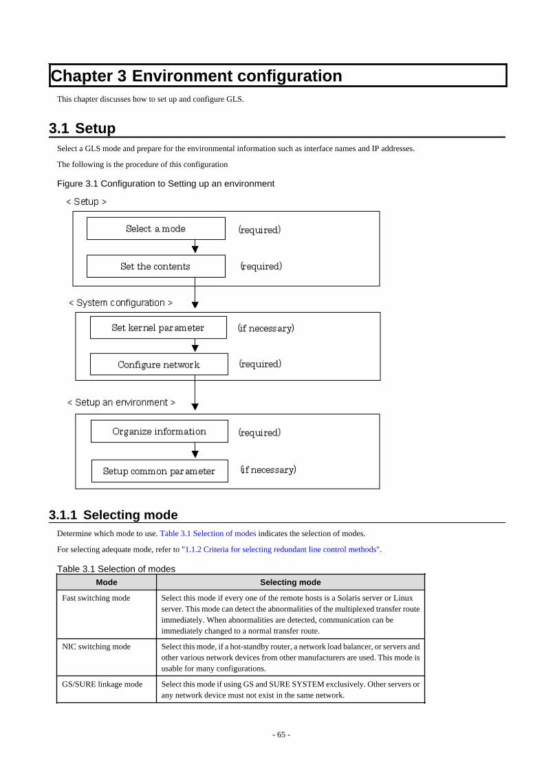
Chapter 3 Environment configurationThis chapter discusses how to set up and configure GLS.
3.1 SetupSelect a GLS mode and prepare for the environmental information such as interface names and IP addresses.
The following is the procedure of this configuration
Figure 3.1 Configuration to Setting up an environment
3.1.1 Selecting modeDetermine which mode to use. Table 3.1 Selection of modes indicates the selection of modes.
For selecting adequate mode, refer to "1.1.2 Criteria for selecting redundant line control methods".
Table 3.1 Selection of modes
Mode Selecting mode
Fast switching mode Select this mode if every one of the remote hosts is a Solaris server or Linuxserver. This mode can detect the abnormalities of the multiplexed transfer routeimmediately. When abnormalities are detected, communication can beimmediately changed to a normal transfer route.
NIC switching mode Select this mode, if a hot-standby router, a network load balancer, or servers andother various network devices from other manufacturers are used. This mode isusable for many configurations.
GS/SURE linkage mode Select this mode if using GS and SURE SYSTEM exclusively. Other servers orany network device must not exist in the same network.
- 65 -
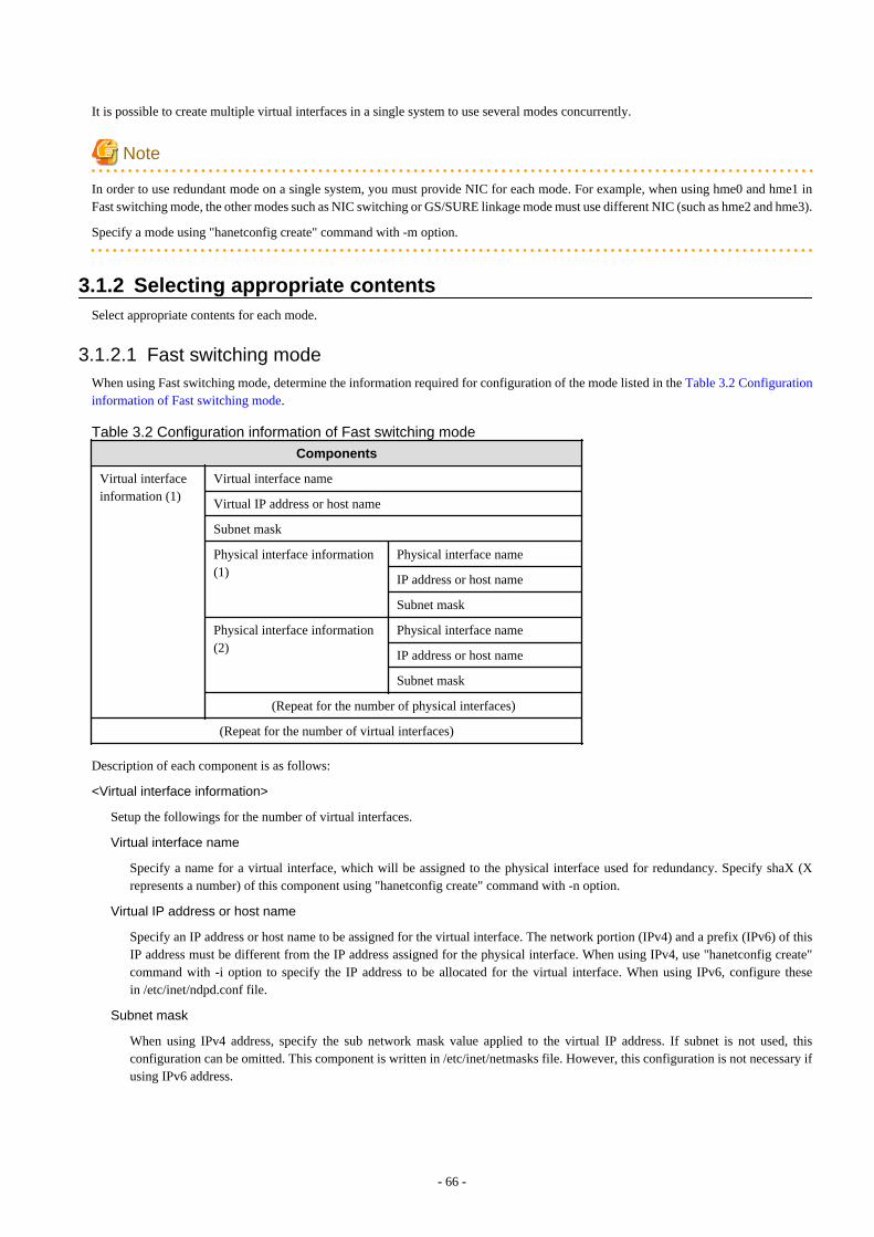
It is possible to create multiple virtual interfaces in a single system to use several modes concurrently.
Note
In order to use redundant mode on a single system, you must provide NIC for each mode. For example, when using hme0 and hme1 inFast switching mode, the other modes such as NIC switching or GS/SURE linkage mode must use different NIC (such as hme2 and hme3).
Specify a mode using "hanetconfig create" command with -m option.
3.1.2 Selecting appropriate contentsSelect appropriate contents for each mode.
3.1.2.1 Fast switching modeWhen using Fast switching mode, determine the information required for configuration of the mode listed in the Table 3.2 Configurationinformation of Fast switching mode.
Table 3.2 Configuration information of Fast switching mode
Components
Virtual interfaceinformation (1)
Virtual interface name
Virtual IP address or host name
Subnet mask
Physical interface information(1)
Physical interface name
IP address or host name
Subnet mask
Physical interface information(2)
Physical interface name
IP address or host name
Subnet mask
(Repeat for the number of physical interfaces)
(Repeat for the number of virtual interfaces)
Description of each component is as follows:
<Virtual interface information>
Setup the followings for the number of virtual interfaces.
Virtual interface name
Specify a name for a virtual interface, which will be assigned to the physical interface used for redundancy. Specify shaX (Xrepresents a number) of this component using "hanetconfig create" command with -n option.
Virtual IP address or host name
Specify an IP address or host name to be assigned for the virtual interface. The network portion (IPv4) and a prefix (IPv6) of thisIP address must be different from the IP address assigned for the physical interface. When using IPv4, use "hanetconfig create"command with -i option to specify the IP address to be allocated for the virtual interface. When using IPv6, configure thesein /etc/inet/ndpd.conf file.
Subnet mask
When using IPv4 address, specify the sub network mask value applied to the virtual IP address. If subnet is not used, thisconfiguration can be omitted. This component is written in /etc/inet/netmasks file. However, this configuration is not necessary ifusing IPv6 address.
- 66 -
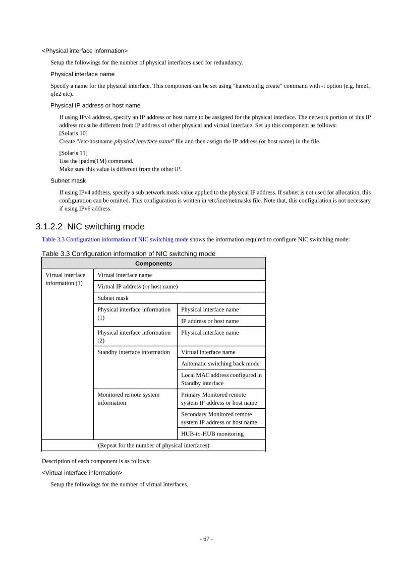
<Physical interface information>
Setup the followings for the number of physical interfaces used for redundancy.
Physical interface name
Specify a name for the physical interface. This component can be set using "hanetconfig create" command with -t option (e.g. hme1,qfe2 etc).
Physical IP address or host name
If using IPv4 address, specify an IP address or host name to be assigned for the physical interface. The network portion of this IPaddress must be different from IP address of other physical and virtual interface. Set up this component as follows:[Solaris 10]Create "/etc/hostname.physical interface name" file and then assign the IP address (or host name) in the file.
[Solaris 11]Use the ipadm(1M) command.Make sure this value is different from the other IP.
Subnet mask
If using IPv4 address, specify a sub network mask value applied to the physical IP address. If subnet is not used for allocation, thisconfiguration can be omitted. This configuration is written in /etc/inet/netmasks file. Note that, this configuration is not necessaryif using IPv6 address.
3.1.2.2 NIC switching modeTable 3.3 Configuration information of NIC switching mode shows the information required to configure NIC switching mode:
Table 3.3 Configuration information of NIC switching mode
Components
Virtual interfaceinformation (1)
Virtual interface name
Virtual IP address (or host name)
Subnet mask
Physical interface information(1)
Physical interface name
IP address or host name
Physical interface information(2)
Physical interface name
Standby interface information Virtual interface name
Automatic switching back mode
Local MAC address configured inStandby interface
Monitored remote systeminformation
Primary Monitored remotesystem IP address or host name
Secondary Monitored remotesystem IP address or host name
HUB-to-HUB monitoring
(Repeat for the number of physical interfaces)
Description of each component is as follows:
<Virtual interface information>
Setup the followings for the number of virtual interfaces.
- 67 -
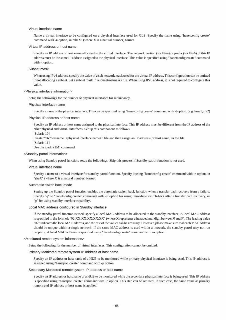
Virtual interface name
Name a virtual interface to be configured on a physical interface used for GLS. Specify the name using "hanetconfig create"command with -n option, in "shaX" (where X is a natural number) format.
Virtual IP address or host name
Specify an IP address or host name allocated to the virtual interface. The network portion (for IPv4) or prefix (for IPv6) of this IPaddress must be the same IP address assigned to the physical interface. This value is specified using "hanetconfig create" commandwith -i option.
Subnet mask
When using IPv4 address, specify the value of a sub network mask used for the virtual IP address. This configuration can be omittedif not allocating a subnet. Set a subnet mask in /etc/inet/netmasks file. When using IPv6 address, it is not required to configure thisvalue.
<Physical interface information>
Setup the followings for the number of physical interfaces for redundancy.
Physical interface name
Specify a name of the physical interface. This can be specified using "hanetconfig create" command with -t option. (e.g. hme1,qfe2)
Physical IP address or host name
Specify an IP address or host name assigned to the physical interface. This IP address must be different from the IP address of theother physical and virtual interfaces. Set up this component as follows:[Solaris 10]Create "/etc/hostname. <physical interface name>" file and then assign an IP address (or host name) in the file.[Solaris 11]Use the ipadm(1M) command.
<Standby patrol information>
When using Standby patrol function, setup the followings. Skip this process if Standby patrol function is not used.
Virtual interface name
Specify a name to a virtual interface for standby patrol function. Specify it using "hanetconfig create" command with -n option, in"shaX" (where X is a natural number) format.
Automatic switch back mode
Setting up the Standby patrol function enables the automatic switch back function when a transfer path recovers from a failure.Specify "q" to "hanetconfig create" command with -m option for using immediate switch-back after a transfer path recovery, or"p" for using standby interface capability.
Local MAC address configured in Standby interface
If the standby patrol function is used, specify a local MAC address to be allocated to the standby interface. A local MAC addressis specified in the form of: "02:XX:XX:XX:XX:XX" (where X represents a hexadecimal digit between 0 and F). The leading value"02" indicates the local MAC address, and the rest of the values can be arbitrary. However, please make sure that each MAC addressshould be unique within a single network. If the same MAC address is used within a network, the standby patrol may not runproperly. A local MAC address is specified using "hanetconfig create" command with -a option.
<Monitored remote system information>
Setup the following for the number of virtual interfaces. This configuration cannot be omitted.
Primary Monitored remote system IP address or host name
Specify an IP address or host name of a HUB to be monitored while primary physical interface is being used. This IP address isassigned using "hanetpoll create" command with -p option.
Secondary Monitored remote system IP address or host name
Specify an IP address or host name of a HUB to be monitored while the secondary physical interface is being used. This IP addressis specified using "hanetpoll create" command with -p option. This step can be omitted. In such case, the same value as primaryremote end IP address or host name is applied.
- 68 -
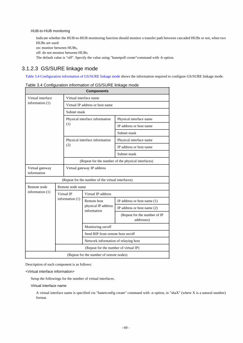
HUB-to-HUB monitoring
Indicate whether the HUB-to-HUB monitoring function should monitor a transfer path between cascaded HUBs or not, when twoHUBs are used:on: monitor between HUBs,off: do not monitor between HUBs.The default value is "off". Specify the value using "hanetpoll create"command with -b option.
3.1.2.3 GS/SURE linkage modeTable 3.4 Configuration information of GS/SURE linkage mode shows the information required to configure GS/SURE linkage mode.
Table 3.4 Configuration information of GS/SURE linkage mode
Components
Virtual interfaceinformation (1)
Virtual interface name
Virtual IP address or host name
Subnet mask
Physical interface information(1)
Physical interface name
IP address or host name
Subnet mask
Physical interface information(2)
Physical interface name
IP address or host name
Subnet mask
(Repeat for the number of the physical interfaces)
Virtual gatewayinformation
Virtual gateway IP address
(Repeat for the number of the virtual interfaces)
Remote nodeinformation (1)
Remote node name
Virtual IPinformation (1)
Virtual IP address
Remote hostphysical IP addressinformation
IP address or host name (1)
IP address or host name (2)
(Repeat for the number of IPaddresses)
Monitoring on/off
Send RIP from remote host on/off
Network information of relaying host
(Repeat for the number of virtual IP)
(Repeat for the number of remote nodes)
Description of each component is as follows:
<Virtual interface information>
Setup the followings for the number of virtual interfaces.
Virtual interface name
A virtual interface name is specified via "hanetconfig create" command with -n option, in "shaX" (where X is a natural number)format.
- 69 -

Virtual IP address or host name
Specify an IPv4 address or host name to be assigned to the virtual interface. The network portion of this IP address must be differentfrom the IP address assigned to the physical interface. Virtual IP address or host name is specified via "hanetconfig create" commandwith -i option.
Subnet mask
Specify a sub network mask value applied to the virtual IP address. This procedure can be omitted if not applying a subnet. Subnetmask is specified in /etc/inet/netmasks file. When applying subnet mask, apply the same mask value to the whole virtual andphysical IP.
<Physical interface information>
Setup the followings for the number of physical interfaces for redundancy.
Physical interface name
Specify a name for the physical interface. Physical interface name is specified via "hanetconfig create" command with -t option.
Physical IP address or host name
Specify an IP address or host name to be assigned to the physical interface. The network portion of this IP address must be differentfrom the IP address allocated to the other physical and virtual interfaces. The physical IP address (or host name) is specified via -i option while executing "hanetconfig create" command with -n option. Do not create "/etc/hostname.<physical interface name>"file.
Subnet mask
Specify a sub network value applied to the physical IP address. This procedure can be omitted if not applying a subnet. Subnetmask is specified in /etc/inet/netmasks file. If using subnet mask, apply the same mask value to a whole virtual and physical IP.
<Virtual gateway information>
Setup the following for the number of virtual interfaces.
Virtual gateway IP address
Specify the IP address of the remote virtual gateway. The network (subnet) portion of the IP address should be the same as the IPaddress assigned to the virtual interface. This item is specified via "hanetgw create" command with -g option.
<Remote node information>
Configure the following for the number of host nodes.
Remote host name
Specify an arbitrary name (within 16 one-bit characters) to identify the node of remote host. Remote host name is specified via"hanetobserv create" command with -n option.
<Virtual IP information>
Setup the followings for the number of virtual IP.
Virtual IP address or host name
Specify a virtual IP address or host name of the remote host. The virtual IP address or host name is specified via "hanetobservcreate" command with -i option. Also, the host name and IP address must be defined in /etc/inet/hosts file.
Remote host physical IP address information
Specify a physical IP address or host name in the virtual IP of the remote host. List these physical IP addresses separated by ','(commas). Remote host physical IP address information is specified via "hanetobserv create" command with -t option. The IPaddress and the host name specified here must be defined in /etc/inet/hosts file as well.
Monitoring on/off
Set whether or not to use monitoring function.on: Turn on the monitoring function from the local hostoff: Does not turn on the monitoring.If monitoring is enabled from the remote host, monitoring the remote host can be omitted. Check the configuration of the remotehost and decide whether or not to turn on the monitoring function.
- 70 -
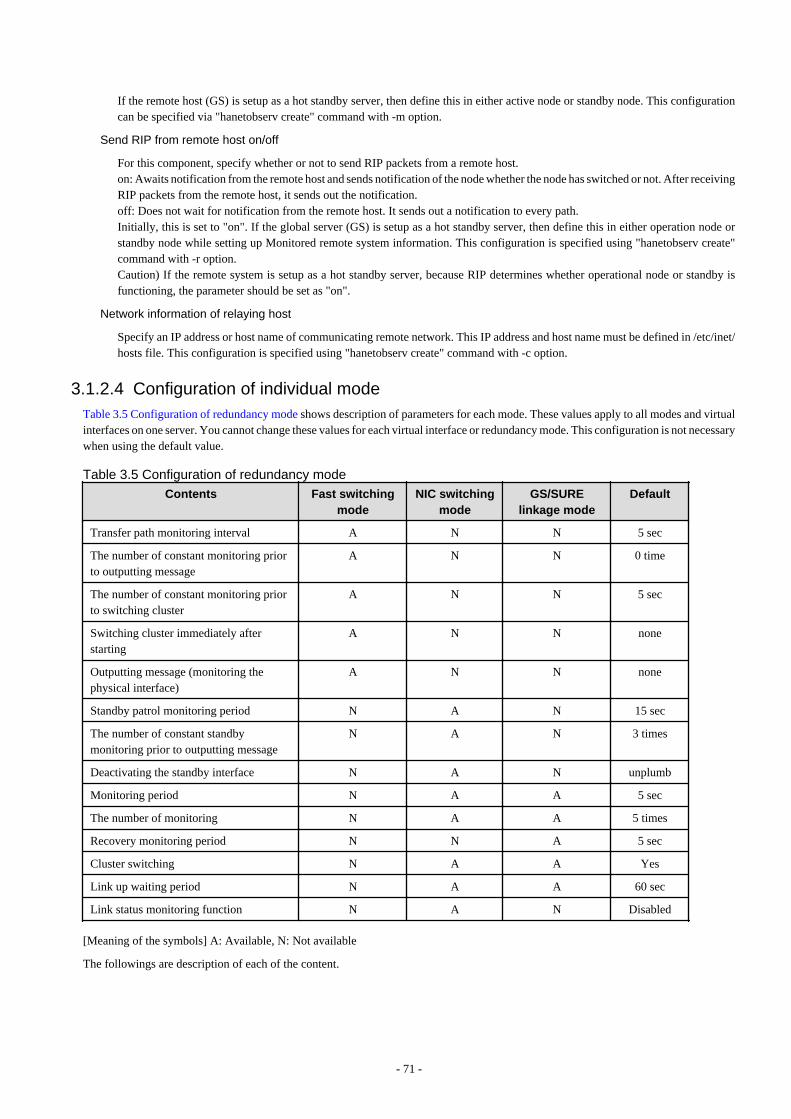
If the remote host (GS) is setup as a hot standby server, then define this in either active node or standby node. This configurationcan be specified via "hanetobserv create" command with -m option.
Send RIP from remote host on/off
For this component, specify whether or not to send RIP packets from a remote host.on: Awaits notification from the remote host and sends notification of the node whether the node has switched or not. After receivingRIP packets from the remote host, it sends out the notification.off: Does not wait for notification from the remote host. It sends out a notification to every path. Initially, this is set to "on". If the global server (GS) is setup as a hot standby server, then define this in either operation node orstandby node while setting up Monitored remote system information. This configuration is specified using "hanetobserv create"command with -r option.Caution) If the remote system is setup as a hot standby server, because RIP determines whether operational node or standby isfunctioning, the parameter should be set as "on".
Network information of relaying host
Specify an IP address or host name of communicating remote network. This IP address and host name must be defined in /etc/inet/hosts file. This configuration is specified using "hanetobserv create" command with -c option.
3.1.2.4 Configuration of individual modeTable 3.5 Configuration of redundancy mode shows description of parameters for each mode. These values apply to all modes and virtualinterfaces on one server. You cannot change these values for each virtual interface or redundancy mode. This configuration is not necessarywhen using the default value.
Table 3.5 Configuration of redundancy mode
Contents Fast switchingmode
NIC switchingmode
GS/SURElinkage mode
Default
Transfer path monitoring interval A N N 5 sec
The number of constant monitoring priorto outputting message
A N N 0 time
The number of constant monitoring priorto switching cluster
A N N 5 sec
Switching cluster immediately afterstarting
A N N none
Outputting message (monitoring thephysical interface)
A N N none
Standby patrol monitoring period N A N 15 sec
The number of constant standbymonitoring prior to outputting message
N A N 3 times
Deactivating the standby interface N A N unplumb
Monitoring period N A A 5 sec
The number of monitoring N A A 5 times
Recovery monitoring period N N A 5 sec
Cluster switching N A A Yes
Link up waiting period N A A 60 sec
Link status monitoring function N A N Disabled
[Meaning of the symbols] A: Available, N: Not available
The followings are description of each of the content.
- 71 -
Transfer path monitoring interval
Specify the transfer path monitoring interval in seconds. The range of the intervals that can be specified is from 0 to 300 sec. If "0" isspecified, it will not monitor the transfer path. Initially, it is set to 5 seconds. The transfer path monitoring interval is set using"hanetparam" command with -w option. This feature is available for Fast switching mode.
The number of constant monitoring prior to message output
Specify the number of times for monitoring before outputting the message (No: 800 or 801) if the message needs to be output as atransfer path failure is detected. The effective range of the numbers which can be specified is from 0 to 100. If "0" is specified, it willnot output a message. Initially it is set to 0 (does not output any message). using "hanetparam" command of -m option. Note that thisfeature is only available for Fast switching mode.
The number of constant monitoring prior to switching cluster
Specify whether or not to switch over the cluster if a failure occurs on a whole transfer path of the virtual interface. The effective rangeof the numbers is from 0 to 100. it will not switch the cluster. When configuring to switch the cluster, set how many times it repeatedlymonitors. The range is from 1 to 100. Initially, it is set to 5, meaning that a cluster failover is triggered after continuously detectingthe same failure 5 times. This feature is specified using "hanetparam" command with -i option. This feature is available only for Fastswitching.
Switching cluster immediately after starting
Specify whether or not to switch the cluster immediately after the cluster starts up. Configure this if a failure occurs in entire transferpath of the virtual interface before the system starts up. The values which can be specified are either "on" or "off". If "on" is selected,cluster is switched immediately after the userApplication starts up. On the other hand, if "off" is selected, the cluster is not switchedeven after the userApplication starts up. As an initial value, it is set to "off". This setting is specified using "hanetparam" commandwith -c option. This is available for Fast switching.
Outputting message (monitoring the physical interface)
Configure whether or not to output a message when the status of the physical interface changes (detecting a failure in transfer path ortransfer path recover) in the virtual interface. The values which can be specified are either "on" or "off". If "on" is selected, a message(message number: 990, 991, 992) is output. If "off" is selected, a message is not output. Initially, it is set to "off". This setting is specifiedvia "hanetparam" command with -s option. This is available for Fast switching.
Standby patrol monitoring period
Specify the monitoring interval (in seconds) of operational NIC for standby patrol function. The values which can be specified arefrom 0 to 100. If "0" is specified, it will not run monitoring. Note if the user command function (using user command when standbypatrol fails or detects recovery) is enabled, do not set the parameter to "0". If the parameter is set to "0", the user command functionwill not work. Initially, the parameter is set to 15 (seconds). This setting is specified via "hanetparam" command with -p option. Thisconfiguration is available for NIC switching mode with standby patrol function is enabled.
The number of constant standby monitoring prior to outputting message
When a failure is detected in a transfer path using the standby patrol function, a message will be output to inform the failure. In thissection, specify how many times to monitor until the message (message number: 875) is output. The values which can be specifiedare from 0 to 100. If "0" is selected, it stops outputting a message and disables monitoring using the standby patrol function. Note ifthe user command function (using user command when standby patrol fails or detects recovery) is enabled, do not set the parameterto "0". If the parameter is set to "0", the user command function will not work. Initially, the parameter is set to 3 (times). Thisconfiguration is specified via "hanetparam" command with -o option. This is available in NIC switching mode, which uses the standbypatrol function. Using this option, the number of monitoring times doubles immediately after the standby patrol starts.
Deactivating the standby interface
Specify how the standby interface is deactivated. The values which can be specified are either "plumb" or "unplumb". If "plumb"parameter is specified, the standby interface is deactivated and sets "0.0.0.0" for the IP address. With this parameter, it is possible touse "INTERSTAGE Traffic Director" as a high-level application. On the other hand, selecting "unplumb" deactivates the standbyinterface and then it sets to unused status. Initially, the parameter is set to "unplumb".
Specify "plumb" for the following situations:
- When configuring high-reliable networks of non-global zones in the shared-ip configuration with the NIC switching mode
- When configuring high-reliable LinkAggregation which the LACP mode is active with the NIC switching mode
This configuration is specified by "hanetparam" command with -d option. This is available exclusively for NIC switching mode.
- 72 -

Monitoring period
Specify the monitoring period in seconds. The values which can be specified are from 1 to 300. The default value is 5 (seconds). Thisconfiguration is specified by "hanetpoll on" command with -s option. This feature is available for NIC switching and GS/SURE linkagemode.
The number of monitoring
Specify the number of monitoring times. The values which can be specified are from 1 to 300. The default value is 5 (times). Thisconfiguration is specified using "hanetpoll on" command with -c option. This feature is available for NIC switching and GS/SUREmode.
Recovery monitoring period
Specify the monitoring period when a failure is detected by monitoring the remote host by GS/SURE linkage mode. The values whichcan be specified are from 0 to 300. The default value is 5 (seconds). This configuration is assigned via "hanetpoll on" command with-b option. This feature is available for GS/SURE linkage mode.
Cluster switching
Specify whether or not to switch the node when a failure occurs to every transfer paths.yes: Switch nodes when a failure occurs to a whole transfer paths.no: Does not switch nodes when a failure occurs to a whole transfer path.The default parameter is "yes". This configuration is specified by "hanetpoll on" command with -f. This feature is available for NICswitching and GS/SURE linkage mode operating as a cluster.
Link up waiting period
In NIC switching mode, specify the time period (in seconds) until the HUB links up after monitoring starts. The values which can bespecified are from 1 to 300. If this option is not specified, then the default value is used. Initial value is set to 60 (seconds). If the valueis less than the product of monitoring period and monitoring times ("monitoring period" multiplied by "monitoring times"), then thevalue is ignored and ends up using the value of the product of monitoring period and monitoring times. This configuration is specifiedby "hanetpoll on" command with -p option. This feature is available for NIC switching and GS/SURE linkage mode.
Link status monitoring function
Specify whether to monitor the link state of the NICs in the virtual interface bundles. The link state is monitored at intervals set byusing the -s option of the hanetpoll on command, and GLS immediately performs NIC switching when NIC link down is detected.Also, to switch NICs by detecting an error by the transfer path monitoring, check the link status of the NIC which is the destinationof switching beforehand. If NIC is in link down state and the state continues for over 5 seconds (when the standby patrol is set: over2.5 seconds), switching will be restricted. Specify this monitoring with the -l option of the hanetpoll on command. This function isenabled in NIC switching mode.
3.1.2.5 Upper limit of configurationThe following describes the upper limit of configuration in each mode.
Upper limit of redundant line control methods
The following table lists the upper limit of configuration items set in the redundant line control methods.
Configuration item Upper limit
Total number of virtual interfaces and logical virtual interfaces 64
See
For information on how to set the upper limit, refer to "7.1 hanetconfig Command".
Upper limit of GS/SURE linkage mode
The following table lists the upper limit of configuration items set for communication host monitoring for GS/SURE linkage mode.
- 73 -
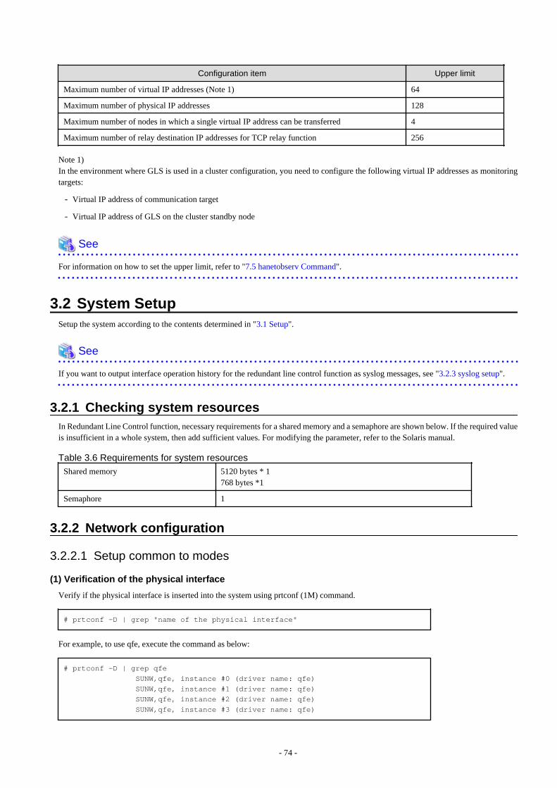
Configuration item Upper limit
Maximum number of virtual IP addresses (Note 1) 64
Maximum number of physical IP addresses 128
Maximum number of nodes in which a single virtual IP address can be transferred 4
Maximum number of relay destination IP addresses for TCP relay function 256
Note 1)In the environment where GLS is used in a cluster configuration, you need to configure the following virtual IP addresses as monitoringtargets:
- Virtual IP address of communication target
- Virtual IP address of GLS on the cluster standby node
See
For information on how to set the upper limit, refer to "7.5 hanetobserv Command".
3.2 System SetupSetup the system according to the contents determined in "3.1 Setup".
See
If you want to output interface operation history for the redundant line control function as syslog messages, see "3.2.3 syslog setup".
3.2.1 Checking system resourcesIn Redundant Line Control function, necessary requirements for a shared memory and a semaphore are shown below. If the required valueis insufficient in a whole system, then add sufficient values. For modifying the parameter, refer to the Solaris manual.
Table 3.6 Requirements for system resources
Shared memory 5120 bytes * 1768 bytes *1
Semaphore 1
3.2.2 Network configuration
3.2.2.1 Setup common to modes
(1) Verification of the physical interface
Verify if the physical interface is inserted into the system using prtconf (1M) command.
# prtconf -D | grep "name of the physical interface"
For example, to use qfe, execute the command as below:
# prtconf -D | grep qfe SUNW,qfe, instance #0 (driver name: qfe) SUNW,qfe, instance #1 (driver name: qfe) SUNW,qfe, instance #2 (driver name: qfe) SUNW,qfe, instance #3 (driver name: qfe)
- 74 -
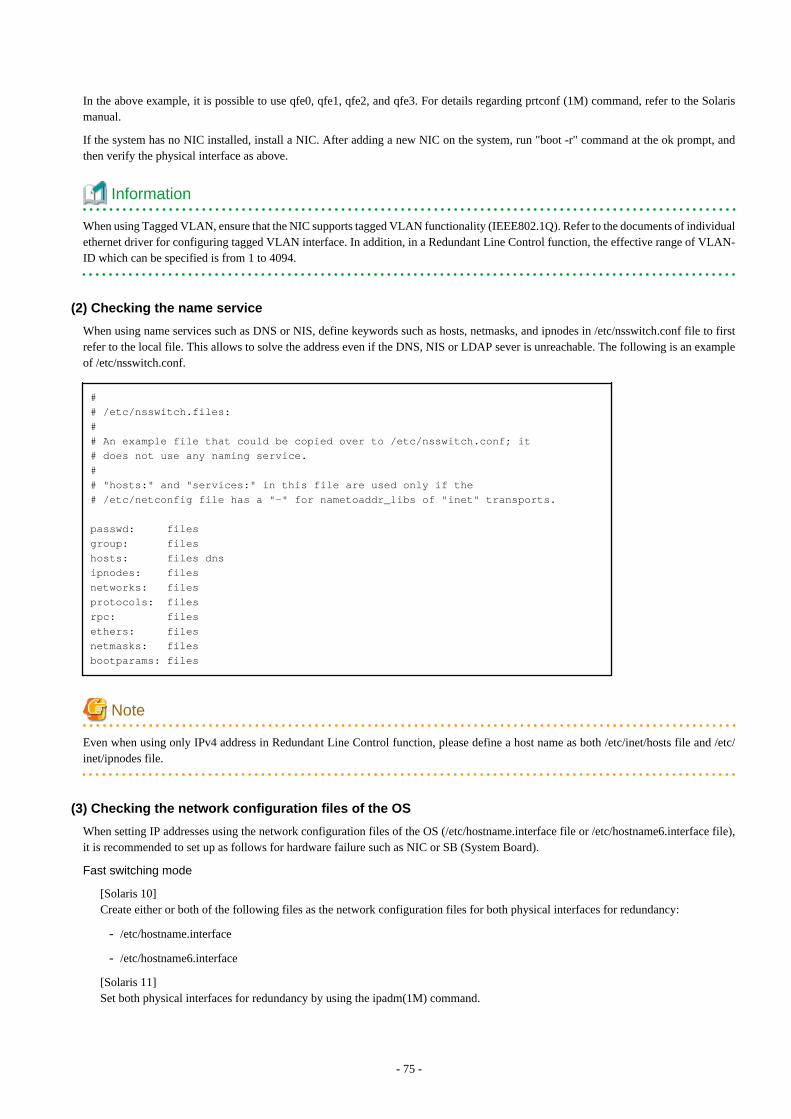
In the above example, it is possible to use qfe0, qfe1, qfe2, and qfe3. For details regarding prtconf (1M) command, refer to the Solarismanual.
If the system has no NIC installed, install a NIC. After adding a new NIC on the system, run "boot -r" command at the ok prompt, andthen verify the physical interface as above.
Information
When using Tagged VLAN, ensure that the NIC supports tagged VLAN functionality (IEEE802.1Q). Refer to the documents of individualethernet driver for configuring tagged VLAN interface. In addition, in a Redundant Line Control function, the effective range of VLAN-ID which can be specified is from 1 to 4094.
(2) Checking the name service
When using name services such as DNS or NIS, define keywords such as hosts, netmasks, and ipnodes in /etc/nsswitch.conf file to firstrefer to the local file. This allows to solve the address even if the DNS, NIS or LDAP sever is unreachable. The following is an exampleof /etc/nsswitch.conf.
## /etc/nsswitch.files:## An example file that could be copied over to /etc/nsswitch.conf; it# does not use any naming service.## "hosts:" and "services:" in this file are used only if the# /etc/netconfig file has a "-" for nametoaddr_libs of "inet" transports.
passwd: filesgroup: fileshosts: files dnsipnodes: filesnetworks: filesprotocols: filesrpc: filesethers: filesnetmasks: filesbootparams: files
Note
Even when using only IPv4 address in Redundant Line Control function, please define a host name as both /etc/inet/hosts file and /etc/inet/ipnodes file.
(3) Checking the network configuration files of the OS
When setting IP addresses using the network configuration files of the OS (/etc/hostname.interface file or /etc/hostname6.interface file),it is recommended to set up as follows for hardware failure such as NIC or SB (System Board).
Fast switching mode
[Solaris 10]Create either or both of the following files as the network configuration files for both physical interfaces for redundancy:
- /etc/hostname.interface
- /etc/hostname6.interface
[Solaris 11]Set both physical interfaces for redundancy by using the ipadm(1M) command.
- 75 -
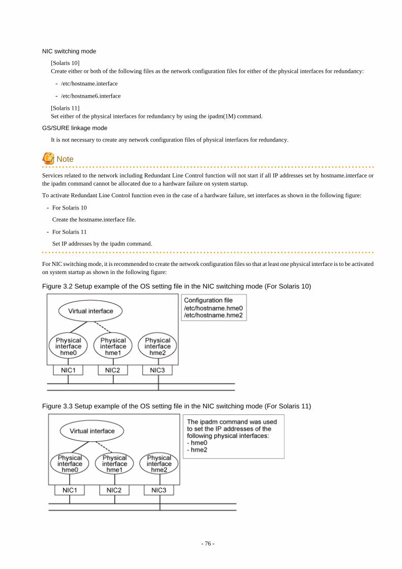
NIC switching mode
[Solaris 10]Create either or both of the following files as the network configuration files for either of the physical interfaces for redundancy:
- /etc/hostname.interface
- /etc/hostname6.interface
[Solaris 11]Set either of the physical interfaces for redundancy by using the ipadm(1M) command.
GS/SURE linkage mode
It is not necessary to create any network configuration files of physical interfaces for redundancy.
Note
Services related to the network including Redundant Line Control function will not start if all IP addresses set by hostname.interface orthe ipadm command cannot be allocated due to a hardware failure on system startup.
To activate Redundant Line Control function even in the case of a hardware failure, set interfaces as shown in the following figure:
- For Solaris 10
Create the hostname.interface file.
- For Solaris 11
Set IP addresses by the ipadm command.
For NIC switching mode, it is recommended to create the network configuration files so that at least one physical interface is to be activatedon system startup as shown in the following figure:
Figure 3.2 Setup example of the OS setting file in the NIC switching mode (For Solaris 10)
Figure 3.3 Setup example of the OS setting file in the NIC switching mode (For Solaris 11)
- 76 -
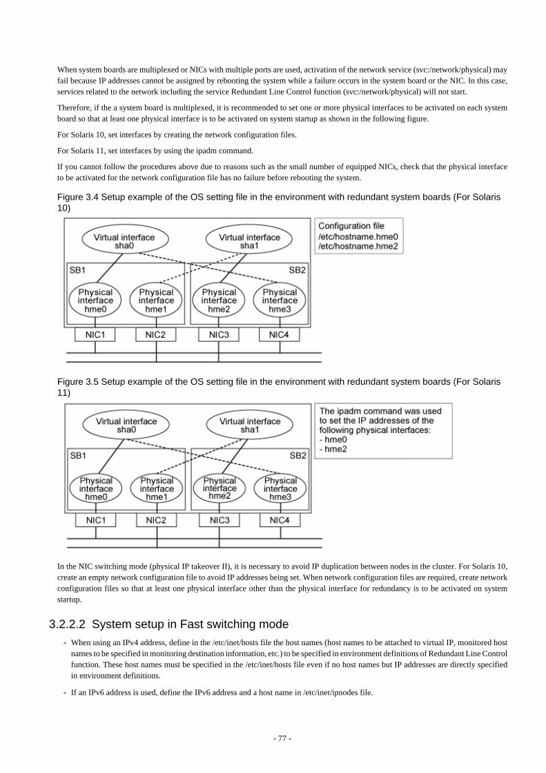
When system boards are multiplexed or NICs with multiple ports are used, activation of the network service (svc:/network/physical) mayfail because IP addresses cannot be assigned by rebooting the system while a failure occurs in the system board or the NIC. In this case,services related to the network including the service Redundant Line Control function (svc:/network/physical) will not start.
Therefore, if the a system board is multiplexed, it is recommended to set one or more physical interfaces to be activated on each systemboard so that at least one physical interface is to be activated on system startup as shown in the following figure.
For Solaris 10, set interfaces by creating the network configuration files.
For Solaris 11, set interfaces by using the ipadm command.
If you cannot follow the procedures above due to reasons such as the small number of equipped NICs, check that the physical interfaceto be activated for the network configuration file has no failure before rebooting the system.
Figure 3.4 Setup example of the OS setting file in the environment with redundant system boards (For Solaris10)
Figure 3.5 Setup example of the OS setting file in the environment with redundant system boards (For Solaris11)
In the NIC switching mode (physical IP takeover II), it is necessary to avoid IP duplication between nodes in the cluster. For Solaris 10,create an empty network configuration file to avoid IP addresses being set. When network configuration files are required, create networkconfiguration files so that at least one physical interface other than the physical interface for redundancy is to be activated on systemstartup.
3.2.2.2 System setup in Fast switching mode- When using an IPv4 address, define in the /etc/inet/hosts file the host names (host names to be attached to virtual IP, monitored host
names to be specified in monitoring destination information, etc.) to be specified in environment definitions of Redundant Line Controlfunction. These host names must be specified in the /etc/inet/hosts file even if no host names but IP addresses are directly specifiedin environment definitions.
- If an IPv6 address is used, define the IPv6 address and a host name in /etc/inet/ipnodes file.
- 77 -
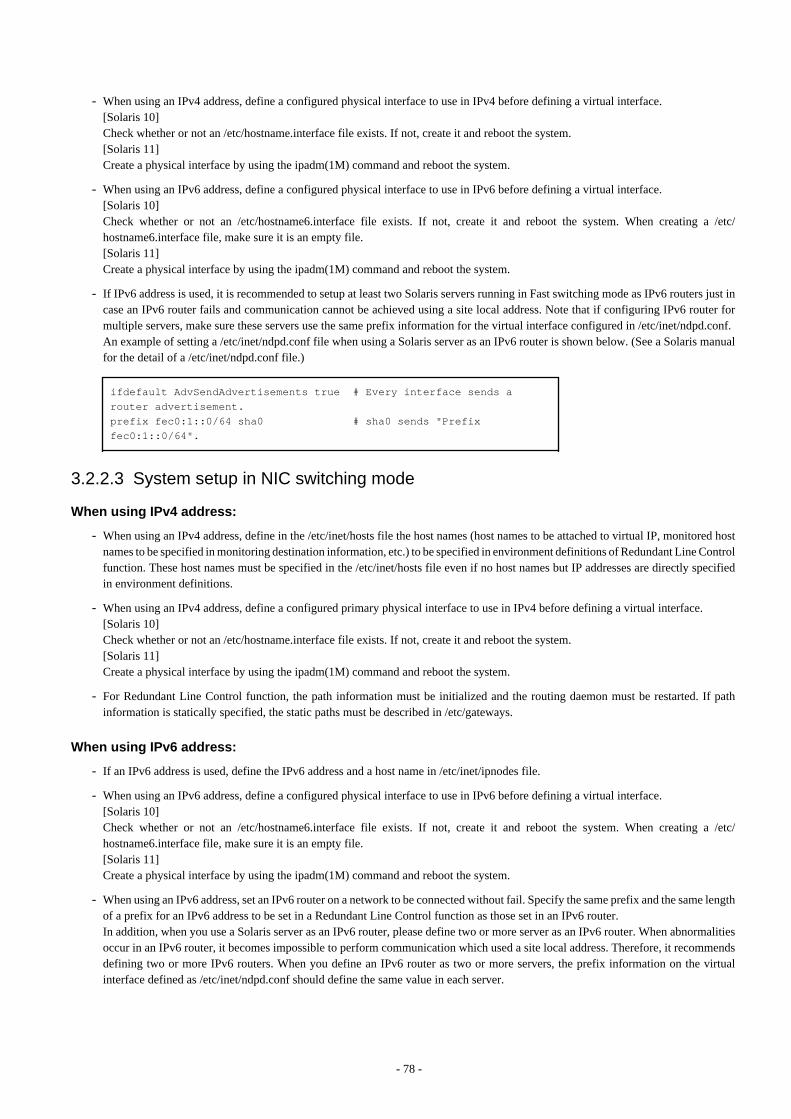
- When using an IPv4 address, define a configured physical interface to use in IPv4 before defining a virtual interface.[Solaris 10]Check whether or not an /etc/hostname.interface file exists. If not, create it and reboot the system.[Solaris 11]Create a physical interface by using the ipadm(1M) command and reboot the system.
- When using an IPv6 address, define a configured physical interface to use in IPv6 before defining a virtual interface.[Solaris 10]Check whether or not an /etc/hostname6.interface file exists. If not, create it and reboot the system. When creating a /etc/hostname6.interface file, make sure it is an empty file.[Solaris 11]Create a physical interface by using the ipadm(1M) command and reboot the system.
- If IPv6 address is used, it is recommended to setup at least two Solaris servers running in Fast switching mode as IPv6 routers just incase an IPv6 router fails and communication cannot be achieved using a site local address. Note that if configuring IPv6 router formultiple servers, make sure these servers use the same prefix information for the virtual interface configured in /etc/inet/ndpd.conf. An example of setting a /etc/inet/ndpd.conf file when using a Solaris server as an IPv6 router is shown below. (See a Solaris manualfor the detail of a /etc/inet/ndpd.conf file.)
ifdefault AdvSendAdvertisements true # Every interface sends a router advertisement.prefix fec0:1::0/64 sha0 # sha0 sends "Prefix fec0:1::0/64".
3.2.2.3 System setup in NIC switching mode
When using IPv4 address:
- When using an IPv4 address, define in the /etc/inet/hosts file the host names (host names to be attached to virtual IP, monitored hostnames to be specified in monitoring destination information, etc.) to be specified in environment definitions of Redundant Line Controlfunction. These host names must be specified in the /etc/inet/hosts file even if no host names but IP addresses are directly specifiedin environment definitions.
- When using an IPv4 address, define a configured primary physical interface to use in IPv4 before defining a virtual interface.[Solaris 10]Check whether or not an /etc/hostname.interface file exists. If not, create it and reboot the system.[Solaris 11]Create a physical interface by using the ipadm(1M) command and reboot the system.
- For Redundant Line Control function, the path information must be initialized and the routing daemon must be restarted. If pathinformation is statically specified, the static paths must be described in /etc/gateways.
When using IPv6 address:
- If an IPv6 address is used, define the IPv6 address and a host name in /etc/inet/ipnodes file.
- When using an IPv6 address, define a configured physical interface to use in IPv6 before defining a virtual interface.[Solaris 10] Check whether or not an /etc/hostname6.interface file exists. If not, create it and reboot the system. When creating a /etc/hostname6.interface file, make sure it is an empty file.[Solaris 11]Create a physical interface by using the ipadm(1M) command and reboot the system.
- When using an IPv6 address, set an IPv6 router on a network to be connected without fail. Specify the same prefix and the same lengthof a prefix for an IPv6 address to be set in a Redundant Line Control function as those set in an IPv6 router.In addition, when you use a Solaris server as an IPv6 router, please define two or more server as an IPv6 router. When abnormalitiesoccur in an IPv6 router, it becomes impossible to perform communication which used a site local address. Therefore, it recommendsdefining two or more IPv6 routers. When you define an IPv6 router as two or more servers, the prefix information on the virtualinterface defined as /etc/inet/ndpd.conf should define the same value in each server.
- 78 -
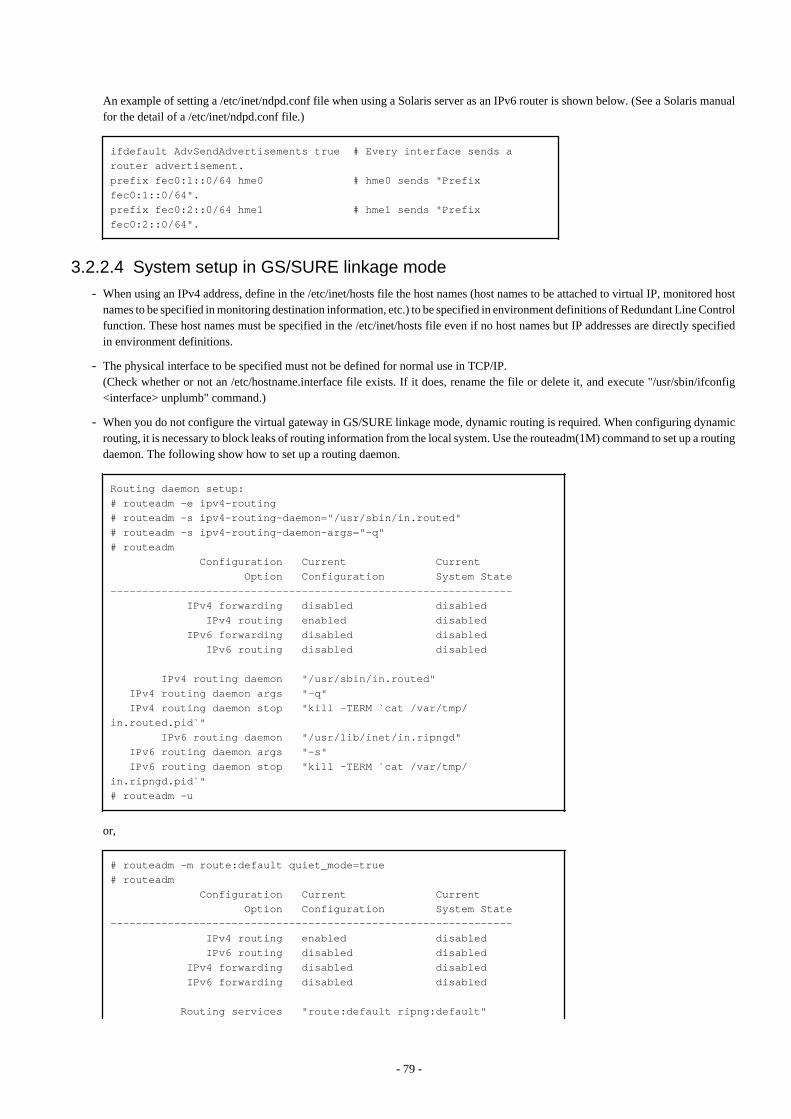
An example of setting a /etc/inet/ndpd.conf file when using a Solaris server as an IPv6 router is shown below. (See a Solaris manualfor the detail of a /etc/inet/ndpd.conf file.)
ifdefault AdvSendAdvertisements true # Every interface sends a router advertisement.prefix fec0:1::0/64 hme0 # hme0 sends "Prefix fec0:1::0/64".prefix fec0:2::0/64 hme1 # hme1 sends "Prefix fec0:2::0/64".
3.2.2.4 System setup in GS/SURE linkage mode- When using an IPv4 address, define in the /etc/inet/hosts file the host names (host names to be attached to virtual IP, monitored host
names to be specified in monitoring destination information, etc.) to be specified in environment definitions of Redundant Line Controlfunction. These host names must be specified in the /etc/inet/hosts file even if no host names but IP addresses are directly specifiedin environment definitions.
- The physical interface to be specified must not be defined for normal use in TCP/IP.(Check whether or not an /etc/hostname.interface file exists. If it does, rename the file or delete it, and execute "/usr/sbin/ifconfig<interface> unplumb" command.)
- When you do not configure the virtual gateway in GS/SURE linkage mode, dynamic routing is required. When configuring dynamicrouting, it is necessary to block leaks of routing information from the local system. Use the routeadm(1M) command to set up a routingdaemon. The following show how to set up a routing daemon.
Routing daemon setup:# routeadm -e ipv4-routing# routeadm -s ipv4-routing-daemon="/usr/sbin/in.routed"# routeadm -s ipv4-routing-daemon-args="-q"# routeadm Configuration Current Current Option Configuration System State--------------------------------------------------------------- IPv4 forwarding disabled disabled IPv4 routing enabled disabled IPv6 forwarding disabled disabled IPv6 routing disabled disabled
IPv4 routing daemon "/usr/sbin/in.routed" IPv4 routing daemon args "-q" IPv4 routing daemon stop "kill -TERM `cat /var/tmp/in.routed.pid`" IPv6 routing daemon "/usr/lib/inet/in.ripngd" IPv6 routing daemon args "-s" IPv6 routing daemon stop "kill -TERM `cat /var/tmp/in.ripngd.pid`"# routeadm -u
or,
# routeadm -m route:default quiet_mode=true# routeadm Configuration Current Current Option Configuration System State--------------------------------------------------------------- IPv4 routing enabled disabled IPv6 routing disabled disabled IPv4 forwarding disabled disabled IPv6 forwarding disabled disabled
Routing services "route:default ripng:default"
- 79 -
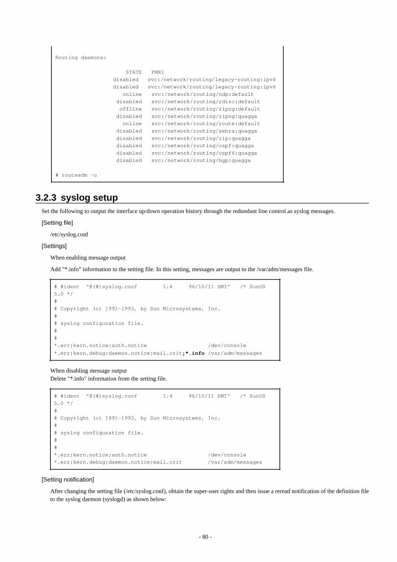
Routing daemons:
STATE FMRI disabled svc:/network/routing/legacy-routing:ipv4 disabled svc:/network/routing/legacy-routing:ipv6 online svc:/network/routing/ndp:default disabled svc:/network/routing/rdisc:default offline svc:/network/routing/ripng:default disabled svc:/network/routing/ripng:quagga online svc:/network/routing/route:default disabled svc:/network/routing/zebra:quagga disabled svc:/network/routing/rip:quagga disabled svc:/network/routing/ospf:quagga disabled svc:/network/routing/ospf6:quagga disabled svc:/network/routing/bgp:quagga
# routeadm -u
3.2.3 syslog setupSet the following to output the interface up/down operation history through the redundant line control as syslog messages.
[Setting file]
/etc/syslog.conf
[Settings]
When enabling message output
Add "*.info" information to the setting file. In this setting, messages are output to the /var/adm/messages file.
# #ident "@(#)syslog.conf 1.4 96/10/11 SMI" /* SunOS 5.0 */## Copyright (c) 1991-1993, by Sun Microsystems, Inc.## syslog configuration file.##*.err;kern.notice;auth.notice /dev/console
*.err;kern.debug;daemon.notice;mail.crit;*.info /var/adm/messages
When disabling message outputDelete "*.info" information from the setting file.
# #ident "@(#)syslog.conf 1.4 96/10/11 SMI" /* SunOS 5.0 */## Copyright (c) 1991-1993, by Sun Microsystems, Inc.## syslog configuration file.##*.err;kern.notice;auth.notice /dev/console*.err;kern.debug;daemon.notice;mail.crit /var/adm/messages
[Setting notification]
After changing the setting file (/etc/syslog.conf), obtain the super-user rights and then issue a reread notification of the definition fileto the syslog daemon (syslogd) as shown below:
- 80 -
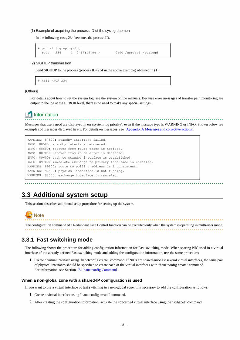
(1) Example of acquiring the process ID of the syslog daemon
In the following case, 234 becomes the process ID.
# ps -ef | grep syslogd root 234 1 0 17:19:04 ? 0:00 /usr/sbin/syslogd
(2) SIGHUP transmission
Send SIGHUP to the process (process ID=234 in the above example) obtained in (1).
# kill -HUP 234
[Others]
For details about how to set the system log, see the system online manuals. Because error messages of transfer path monitoring areoutput to the log at the ERROR level, there is no need to make any special settings.
Information
Messages that users need are displayed in err (system log priority), even if the message type is WARNING or INFO. Shown below areexamples of messages displayed in err. For details on messages, see "Appendix A Messages and corrective actions".
WARNING: 87500: standby interface failed.INFO: 88500: standby interface recovered.INFO: 88600: recover from route error is noticed.INFO: 88700: recover from route error is detected.INFO: 89600: path to standby interface is established.INFO: 89700: immediate exchange to primary interface is canceled.WARNING: 89900: route to polling address is inconsistent.WARNING: 92400: physical interface is not running.WARNING: 92500: exchange interface is canceled.
3.3 Additional system setupThis section describes additional setup procedure for setting up the system.
Note
The configuration command of a Redundant Line Control function can be executed only when the system is operating in multi-user mode.
3.3.1 Fast switching modeThe following shows the procedure for adding configuration information for Fast switching mode. When sharing NIC used in a virtualinterface of the already defined Fast switching mode and adding the configuration information, use the same procedure:
1. Create a virtual interface using "hanetconfig create" command. If NICs are shared amongst several virtual interfaces, the same pairof physical interfaces should be specified to create each of the virtual interfaces with "hanetconfig create" command.For information, see Section "7.1 hanetconfig Command".
When a non-global zone with a shared-IP configuration is used
If you want to use a virtual interface of fast switching in a non-global zone, it is necessary to add the configuration as follows:
1. Create a virtual interface using "hanetconfig create" command.
2. After creating the configuration information, activate the concerned virtual interface using the "strhanet" command.
- 81 -
3. Create a non-global zone. For information on how to create a zone, see "C.5 Configuration Procedure for Redundant Line SwitchingMode on Solaris Zones".
4. Start the non-global zone. The logical virtual interface (sha0:X) will be added to the virtual interface (sha0) by starting the non-global zone. The IP address specified during creation of the non-global zone will be allocated.
3.3.2 NIC switching modeThe procedure to add the configuration information using NIC unused in the other virtual interfaces is as follows:
1. Set up a virtual interface using the "hanetconfig create" command. For information, see Section "7.1 hanetconfig Command".
2. Set up the standby patrol function using the "hanetconfig create" command (only if the standby patrol function is used). Forinformation, see Section "7.1 hanetconfig Command".
3. Set up the HUB monitoring function using the "hanetpoll create" command. For information, see Section "7.7 hanetpollCommand".
The procedure to share NIC used in a virtual interface of the already defined NIC switching mode and to add the configuration informationis as follows (when using an NIC sharing function):
1. Set a virtual interface with "hanetconfig copy" command. See "7.1 hanetconfig Command" for the detail.
2. Set standby patrol with "hanetconfig create" command. (Only when using a standby patrol function.) It is not necessary to set if astandby patrol function is already set in a virtual interface that already shares NIC. See "7.1 hanetconfig Command" for the detail.
3. Set the HUB monitoring function with "hanetpoll copy" command. See "7.7 hanetpoll Command" for the detail.
When a non-global zone with a shared-IP configuration is used
If you want to use a redundant physical interface of NIC switching in a non-global zone, it is necessary to add the configuration as follows:
1. Set up a virtual interface using the "hanetconfig create" command.
2. Set up the standby patrol function using the "hanetconfig create" command (only if the standby patrol function is used). It is notnecessary to set if a standby patrol function is already set in a virtual interface that already shares NIC.
3. Set up the HUB monitoring function using the "hanetpoll create" command.
4. Specify "plumb" to deactivate a standby interface using the "hanetparam -d" command.
5. After creating the configuration information, activate the concerned virtual interface using the "strhanet" command.
6. Start the HUB monitoring function to monitor the routers/hubs using "hanetpoll on" command.
7. Create a non-global zone. For information on how to create a zone, see "C.5 Configuration Procedure for Redundant Line SwitchingMode on Solaris Zones".
8. Start the non-global zone. The logical virtual interface (hme0:X) will be added to the primary interface (hme0) from the redundantphysical interface (sha0) by staring the non-global zone. The IP address specified during creation of the non-global zone will beallocated.
Note
- In NIC switching mode, physical interfaces are activated or deactivated when switching over the transfer path. However, these changesare not recorded to a log file by default. For recording logs of these processes, refer to "3.2.3 syslog setup".
- In NIC switching mode with tagged VLAN interfaces, configure the standby patrol function on only one of virtual interfaces, if multiplevirtual interfaces exist on the same pair of physical interfaces, and do not configure the standby patrol function on the other virtualinterfaces. Note that, in general, the standby patrol function is not need to be configured on every single virtual interface.
- You cannot build an environment in which only one NIC is shared on multiplex physical interface on NIC switching mode usingtagged VLAN interface.
- When configuring a standby patrol function for a virtual interface which is using the tagged VLAN interfaces, it is required to rebootthe OS in order to enable the standby patrol function. GLS withholds a modification of MAC address of the secondary interface, sothat it prevents communication errors on other tagged VLAN interfaces which are sharing a physical communication line.
- 82 -
- In cluster environments other than the physical IP takeover II, do the following. For details on a cluster environment of the physicalIP takeover II, see "B.4.10 Example of the Cluster system in Physical IP address takeover function II."[Solaris 10]Ensure to specify the same IP address configured in "/etc/hostname.interface" when specifying physical IP addresses by "hanetconfig"command using '-i' or '-e' option.[Solaris 11]Ensure to specify the same IP address configured with the ipadm(1M) command when specifying physical IP addresses by"hanetconfig" command using '-i' or '-e' option.When setting a cluster environment of the physical IP takeover II on Solaris 10, create "/etc/hostname.interface" as an empty file.
- If your HUB is using STP (Spanning Tree Protocol), NIC switching occurs while a failure does not occur on a transmission route. Insuch a case, it is necessary to tune a monitoring parameter of the HUB monitoring function. See "7.7 hanetpoll Command" or "F.2.3.1Switching takes place in NIC switching mode regardless of failure at the monitoring end".
- If you specify a physical interface of NIC switching for the network setting of the Solaris Zones, it is necessary to change the methodof deactivating a standby interface from "unplumb" to "plumb" using the "hanetparam -d" command. For details, see "7.6 hanetparamCommand".
3.3.3 GS/SURE linkage modeThe following shows the procedure for adding configuration information for GS/SURE linkage mode:
1. Set up a virtual interface using the "hanetconfig create" command. For information, see Section "7.1 hanetconfig Command".
2. Set up the remote party monitoring function using the "hanetobserv create" command. For information, see Section "7.5 hanetobservCommand".To change the monitoring period or number of monitoring times of this remote party, use "hanetpoll on" command. Refer to "7.7hanetpoll Command" for details.
3. Configure the virtual gateway information by using the hanetgw create command. For details, see "7.16 hanetgw Command".
3.3.4 Setting parameter for individual modeSee the following procedure for using a value different from the default value indicated in section "3.1.2.4 Configuration of individualmode".
1. Use "hanetparam" command and "hanetpoll on" command for setting up the parameter.For detailed description regarding these commands, see "7.6 hanetparam Command" or "7.7 hanetpoll Command".
2. Reboot the system.
3.4 Changing system setupThis section explains a procedure of modifying the system setup.
Note
- The configuration command of a Redundant Line Control function can be executed only when the system is operating in multi-usermode.
- Once the setup is completed for Redundant Line Control function, the information regarding the host name (host name informationover host database such as /etc/inet/hosts file) cannot be changed. To modify the information on host database, remove RedundantLine Control function configuration, and modify the information on the host database, then reconfigure the system.
Information
Once configuration is completed, "resethanet -s" command allows you to reflect the settings without rebooting the system. For details onthis command refer to "7.15 resethanet Command".
- 83 -
3.4.1 Fast switching modeThe following shows the procedure for changing configuration information for Fast switching mode:
1. Inactivate the concerned virtual interface using the "stphanet" command. For information, see Section "7.3 stphanet Command".
2. Change the configuration information.
3. After changing the configuration information, activate the concerned virtual interface using the "strhanet" command. Forinformation, see Section "7.2 strhanet Command".
The procedure to change the information of a monitoring function is as follows:
1. Change the information of a monitoring function using a "hanetparam" command. See "7.6 hanetparam Command" for the detail.In this case, it is not necessary to reactivate a virtual interface. The information becomes valid immediately after changed.
2. Reboot the system after applying changes.
The following lists the information that can be changed for Fast switching mode. No information can be changed besides the informationlisted below. Delete the concerned definition and add it again.
- Configuration definition informationUse the "hanetconfig" command to change the following information. For information, see Section "7.1 hanetconfig Command".
- Host name or IP address to be attached to a virtual interface or a logical virtual interface
- Interface names to be bundled by a virtual interface
- Monitoring function informationUse the "hanetparam" command to change the following information. For information, see Section "7.6 hanetparam Command".
- Transfer path monitoring interval
- The number of constant monitoring prior to outputting message
- The number of constant monitoring prior to switching cluster
- Timing of activating the virtual interface
- Outputting message (monitoring the physical interface)
- Switching cluster immediately after starting RMS
When a non-global zone with a shared-IP configuration is used
If you want to use a virtual interface of fast switching in a non-global zone, it is necessary to add the configuration as follows;
1. Stop the non-global zone.
2. Inactivate the concerned virtual interface using the "stphanet" command.
3. Change the configuration information.
4. Change the network settings of a non-global zone. For information on how to change the zone network settings such as virtual IPaddress, see "C.5 Configuration Procedure for Redundant Line Switching Mode on Solaris Zones".
5. After changing the configuration information, activate the concerned virtual interface using the "strhanet" command.
6. Start the non-global zone.
3.4.2 NIC switching modeThe procedure to change the configuration information, and the configuration information and the other information at the same time isas follows:
1. Stop the HUB monitoring function using "hanetpoll off" command. See "7.7 hanetpoll Command" for the detail.
2. Deactivate a virtual interface to change using a "stphanet" command. See "7.3 stphanet Command" for the detail.
- 84 -

3. Change the setup information and parameter. (This can be done when executing "hanetpoll on" command for changing the monitoringperiod, the number of monitoring times, the recovery monitoring period, the waiting time for cluster switching and a link-up.)See "7.7 hanetpoll Command" for the detail.
4. Deactivate temporarily all virtual interfaces set in NIC switching mode using a "stphanet" command, then reactivate them using a"strhanet" command. See "7.2 strhanet Command" and "7.3 stphanet Command" for the detail.
5. Start the HUB monitoring function to monitor the routers/hubs using "hanetpoll on" command.(Changes made to the monitoring period, the number of monitoring times, the monitoring recovery period, the waiting time for acluster failover, and the waiting time for a link up are reflected when "hanetpoll on" command is executed.)See "7.7 hanetpoll Command" for the detail.
The procedure for enabling a change made on the monitoring information is as follows:
1. Stop the HUB monitoring function using "hanetpoll off" command. See "7.7 hanetpoll Command" for the detail.
2. Start the HUB monitoring function to monitor the routers/hubs using "hanetpoll on" command.(Changes made to the monitoring period, the number of monitoring times, the waiting time for a cluster failover, and the waitingtime for a link up are reflected when "hanetpoll on" command is executed. For more information, refer to "changing configurationand additional information at the same time".)See "7.7 hanetpoll Command" for the detail.
The following lists the information that can be changed for NIC switching mode. No information can be changed besides the informationlisted below. Delete the concerned definition and add it again.
- Configuration definition informationUse the "hanetconfig" command to change the following information. For information, see Section "7.1 hanetconfig Command".
- Host name or IP address to be attached to a virtual interface or a logical virtual interface
- A physical interface name for the virtual interface
- An IP address or host name of the physical interface
- Standby patrol informationUse the "hanetconfig" command to change the following information. For information, see Section "7.1 hanetconfig Command".
- Local MAC address to be allocated to a standby NIC
- Interface names to be bundled by a virtual interface
- Information of monitored remote system and parametersUse the "hanetpoll" command to change the following information. For information, see Section "7.7 hanetpoll Command".
- Information on monitored remote system (primary monitored remote system IP address and secondary monitored remote systemIP address)
- HUB-to-HUB monitoring
- Monitoring interval
- The number of monitoring times
- Cluster switching
- Link up waiting time
Use the "hanetparam" command to change the following information. For information, see Section "7.6 hanetparam Command".
- Standby patrol monitoring interval
- The number of constant standby monitoring prior to outputting message
When a non-global zone with a shared-IP configuration is used
If you want to use a redundant physical interface of NIC switching in a non-global zone, it is necessary to add the configuration as follows:
1. Stop the non-global zone.
2. Stop the HUB monitoring function using "hanetpoll off" command.
- 85 -
3. Deactivate a virtual interface to change using a "stphanet" command.
4. Change the setup information and parameter. (This can be done when executing "hanetpoll on" command for changing the monitoringperiod, the number of monitoring times, the recovery monitoring period, the waiting time for cluster switching and a link-up.)
5. Change the network settings of a non-global zone. For information on how to change the zone network settings such as virtual IPaddress, see "C.5 Configuration Procedure for Redundant Line Switching Mode on Solaris Zones".
6. Deactivate temporarily all virtual interfaces set in NIC switching mode using a "stphanet" command, then reactivate them using a"strhanet" command.
7. Start the HUB monitoring function to monitor the routers/hubs using "hanetpoll on" command.(Changes made to the monitoring period, the number of monitoring times, the monitoring recovery period, the waiting time for acluster failover, and the waiting time for a link up are reflected when "hanetpoll on" command is executed.)
8. Start the non-global zone.
Note
- In cluster environments other than the physical IP takeover II, do the following. For details on a cluster environment of the physicalIP takeover II, see "B.4.10 Example of the Cluster system in Physical IP address takeover function II."[Solaris 10]Ensure to specify the same IP address configured in "/etc/hostname. interface" when specifying physical IP addresses by "hanetconfig"command using '-i' or '-e' option.[Solaris 11]Ensure to specify the same IP address configured with the ipadm(1M) command when specifying physical IP addresses by"hanetconfig" command using '-i' or '-e' option.When setting a cluster environment of the physical IP takeover II on Solaris 10, create "/etc/hostname.interface" as an empty file.
- For NIC sharing and tagged VLAN (synchronous switching), in a configuration in which several virtual interfaces share a singlephysical line, physical interfaces are also inactivated when the last virtual interface is inactivated using the stphanet command.
3.4.3 GS/SURE linkage modeThe following shows the procedure for changing configuration information for GS/SURE linkage mode:
1. Inactivate the concerned virtual interface using the "stphanet" command. For detail, see Section "7.3 stphanet Command".
2. Change the configuration information.
3. Reboot the system.(Note: restarting the HUB monitoring function with "hanetpoll off/on" enables a change made on the monitoring interval, the numberof times for monitoring, the monitoring recovery interval, the waiting time for a link up, or the waiting time for cluster switching.)
The following is a list of the information that can be changed for GS/SURE linkage mode. No information can be changed besides theinformation listed below. Delete the concerned definition and add it again.
- Configuration definition informationUse the "hanetconfig" command to change the following information. For information, see Section "7.1 hanetconfig Command".
- Host name or IP address to be attached to a virtual interface or a logical virtual interface
- Host name or IP address to be attached to a physical interface
- Interface names to be bundled by a virtual interface
- ParametersUse the "hanetpoll" command to change the following information. For information, see Section "7.7 hanetpoll Command".
- Monitoring interval
- The number of monitoring times
- Recovery monitoring period
- Cluster switching
- 86 -
- Link up waiting period
- Remote node informationUse the "hanetobserv" command to change the following information. For information, see Section "7.5 hanetobserv Command".
- Remote node name
- Virtual IP information (Virtual IP address, Remote physical IP address, Monitoring on/off, Send RIP from remote host on/off,Network information of relaying host)
- Virtual gatewayUse the "hanetgw" command to change the following information. For information, see Section "7.16 hanetgw Command".
- Virtual gateway IP address
3.4.4 Note on changing configuration informationThe following shows a note on changing configuration information.
- It is not possible to change the configuration information of a virtual interface registered to a cluster resource. It is necessary to deletethe cluster resource to which the target virtual interface has been registered, and reregister the virtual interface to a cluster resourceafter changing the configuration information.
3.5 Deleting configuration informationThis section explains procedures of deleting various definitions information such as virtual interfaces and monitoring function to be usedfor Redundant Line Control function.
Note
The configuration command of a Redundant Line Control function can be executed only when the system is operating in multi-user mode.
Information
Use the "resethanet" command to delete the entire configured values of the virtual interface for Redundant Line Control function. Fordetails on "resethanet" command, refer to "7.15 resethanet Command".
3.5.1 Fast switching modeThe following shows the procedure for deleting configuration information:
1. Inactivate the concerned virtual interface using the "stphanet" command. For information, see Section "7.3 stphanet Command".
2. Delete the configuration information of the concerned virtual interface. For information, see Section "7.1 hanetconfig Command".
3. Delete the following settings and files:
When using IPv4 addresses
[Solaris 10]Delete the corresponding /etc/hostname.interface file, and then delete host names defined in the /etc/inet/hosts file.
[Solaris 11]Delete the settings by using the ipadm(1M) command, and then delete host names defined in the /etc/inet/hosts.
When using IPv6 addresses
[Solaris 10]Delete the corresponding /etc/hostname6.interface file, and then delete host names defined in the /etc/inet/ipnodes file. Moreover,delete a router public-relations setup from the virtual interface defined in the /etc/inet/ndpd.conf file. When only a router public-relations setup from a virtual interface exists in a /etc/inet/ndpd.conf file, delete the /etc/inet/ndpd.conf file.
- 87 -
[Solaris 11]Delete the settings by using the ipadm(1M) command, and then delete host names defined in the /etc/inet/ipnodes file. Moreover,delete a router public-relations setup from the virtual interface defined in the /etc/inet/ndpd.conf file. When only a router public-relations setup from a virtual interface exists in a /etc/inet/ndpd.conf file, delete the /etc/inet/ndpd.conf file.
When a non-global zone with a shared-IP configuration is used
If you want to use a virtual interface of fast switching in a non-global zone, it is necessary to add the configuration as follows;
1. Stop the non-global zone.
2. Inactivate the concerned virtual interface using the "stphanet" command.
3. Delete the configuration information of the concerned virtual interface.
4. Delete the following settings and files:
When using IPv4 addresses
[Solaris 10]
Delete the corresponding /etc/hostname.interface file, and then delete host names defined in the /etc/inet/hosts file.
[Solaris 11]
Delete the settings by using the ipadm(1M) command, and then delete host names defined in the /etc/inet/hosts.
When using IPv6 addresses
[Solaris 10]
Delete the corresponding /etc/hostname6.interface file, and then delete host names defined in the /etc/inet/ipnodes file. Moreover,delete a router public-relations setup from the virtual interface defined in the /etc/inet/ndpd.conf file. When only a router public-relations setup from a virtual interface exists in a /etc/inet/ndpd.conf file, delete the /etc/inet/ndpd.conf file.
[Solaris 11]
Delete the settings by using the ipadm(1M) command, and then delete host names defined in the /etc/inet/ipnodes file. Moreover,delete a router public-relations setup from the virtual interface defined in the /etc/inet/ndpd.conf file. When only a router public-relations setup from a virtual interface exists in a /etc/inet/ndpd.conf file, delete the /etc/inet/ndpd.conf file.
5. Delete the zone or change the zone network settings. For information on how to change the zone network settings or delete the zone,see "C.5 Configuration Procedure for Redundant Line Switching Mode on Solaris Zones".
3.5.2 NIC switching modeThe following shows the procedure for deleting configuration information:
1. Use the "hanetpoll off" command with '-n' option to stop the HUB polling feature of the virtual interface targeted for deletion. Thiscommand, "hanetpoll off" with '-n' option allows you to stop the virtual interface by specifying them individually. For information,see Section "7.7 hanetpoll Command".
2. Inactivate the virtual interface of the concerned NIC switching mode using the "stphanet" command. To delete the operated definitionin a cluster system, deactivate a virtual interface of the standby patrol using the "stpptl" command (only when using a standby patrolfunction). For information, see Section "7.3 stphanet Command" and Section "7.11 stpptl Command".
3. Delete the concerned monitoring destination information. For information, see Section "7.7 hanetpoll Command".
4. Delete the configuration information of the concerned virtual interface. For information, see Section "7.1 hanetconfig Command".
5. Delete the following settings and files:
When using IPv4 addresses
[Solaris 10]
Delete the corresponding /etc/hostname.interface file, and then delete host names defined in the /etc/inet/hosts file.
[Solaris 11]
Delete the settings by using the ipadm(1M) command, and then delete host names defined in the /etc/inet/hosts.
- 88 -
When using IPv6 addresses
[Solaris 10]
Delete the corresponding /etc/hostname6.interface file, and then delete host names defined in the /etc/inet/ipnodes file.
[Solaris 11]Delete the settings by using the ipadm(1M) command, and then delete host names defined in the /etc/inet/ipnodes file.
When a non-global zone with a shared-IP configuration is used
If you want to use a redundant physical interface of NIC switching in a non-global zone, it is necessary to add the configuration as follows;
1. Stop the non-global zone.
2. Use the "hanetpoll off" command with '-n' option to stop the HUB polling feature of the virtual interface targeted for deletion. Thiscommand, "hanetpoll off" with '-n' option allows you to stop the virtual interface by specifying them individually.
3. Inactivate the virtual interface of the concerned NIC switching mode using the "stphanet" command.If the logical IP address takeover function is set, disable a virtual interface of standby patrol using the "stpptl" command. (only forstandby patrol)
4. If you cancel network high-reliability through NIC switching in all non-global zones, return the method of deactivating a standbyinterface to "unplumb" using the "hanetparam -d" command. If you continue network high-reliability through NIC switching in theother non-global zones, do not return the method of deactivating a standby interface to "unplumb".
5. Delete the concerned monitoring destination information.
6. Delete the configuration information of the concerned virtual interface.
7. Delete the following settings and files:
When using IPv4 addresses
[Solaris 10]
Delete the corresponding /etc/hostname.interface file, and then delete host names defined in the /etc/inet/hosts file.
[Solaris 11]
Delete the settings by using the ipadm(1M) command, and then delete host names defined in the /etc/inet/hosts.
When using IPv6 addresses
[Solaris 10]
Delete the corresponding /etc/hostname6.interface file, and then delete host names defined in the /etc/inet/ipnodes file.
[Solaris 11]Delete the settings by using the ipadm(1M) command, and then delete host names defined in the /etc/inet/ipnodes file.
8. Change the network settings of non-global zones or delete non-global zones. For information on how to change delete non-globalzones, see "C.5 Configuration Procedure for Redundant Line Switching Mode on Solaris Zones".
3.5.3 GS/SURE linkage modeThe following shows the procedure for deleting configuration information:
1. Inactivate the concerned virtual interface using the "stphanet" command. For information, see Section "7.3 stphanet Command".
2. Delete virtual gateway information. For information, see "7.16 hanetgw Command".
3. Delete the monitoring destination information of the concerned communication parties. For information, see Section "7.5hanetobserv Command".
4. Delete the configuration information of the concerned virtual interface. For information, see Section "7.1 hanetconfig Command".
5. Delete the host name defined as the /etc/inet/hosts file.
6. Reboot the system.
- 89 -
3.5.4 Note on deleting configuration informationThe following shows a note on deleting configuration information.
- "hanetconfig delete" command cannot delete a virtual interface that has been used to create a takeover IP resource via "hanethvrsccreate" command. In order to delete the virtual interface, use "hanethvrsc delete" command first to delete the takeover IP resourcethat is created with the target virtual interface, and then issue "hanetconfig delete" command to delete the virtual interface. Refer to"7.14 hanethvrsc Command" for the deletion method of a resource for a virtual interface.
- If deleting all configuration information at once, use the "resethanet" command. See "7.15 resethanet Command" for detail.
3.6 Setting Option Function
3.6.1 Configuring multiple virtual interfacesUse the "hanetconfig" command to set the multiple virtual interfaces setting function. For details about this command, see "7.1 hanetconfigCommand".
3.6.2 Switching cluster when all the transfer paths failsIn Fast switching mode, execute "hanetparam" command to switch the cluster when failure occurs in the whole transfer path, See "7.6hanetparam Command" for detail.
Additionally, if failure occurs in the whole transfer path in NIC switching and GS/SURE linkage modes, use the "hanetpoll" command toswitch the cluster. See "7.7 hanetpoll Command" for detail.
3.6.3 Sharing physical interfaceUse the "hanetconfig" command to set the physical interface sharing function. For details about this command, see the execution examplesin Section "7.1 hanetconfig Command".
3.6.4 Multiple logical virtual interface definitionUse the "hanetconfig" command to set the multiple logical virtual interface definition function. For details about this command, see theexecution examples in Section "7.1 hanetconfig Command".
3.6.5 Single physical interface definitionUse the "hanetconfig" command to set the single physical interface definition function. For details about this command, see the executionexamples in Section "7.1 hanetconfig Command".
3.6.6 HUB monitoring functionSet the HUB monitoring function for the operation in NIC switching mode. Set the HUB monitoring function in accordance with thefollowing procedure:
- 90 -
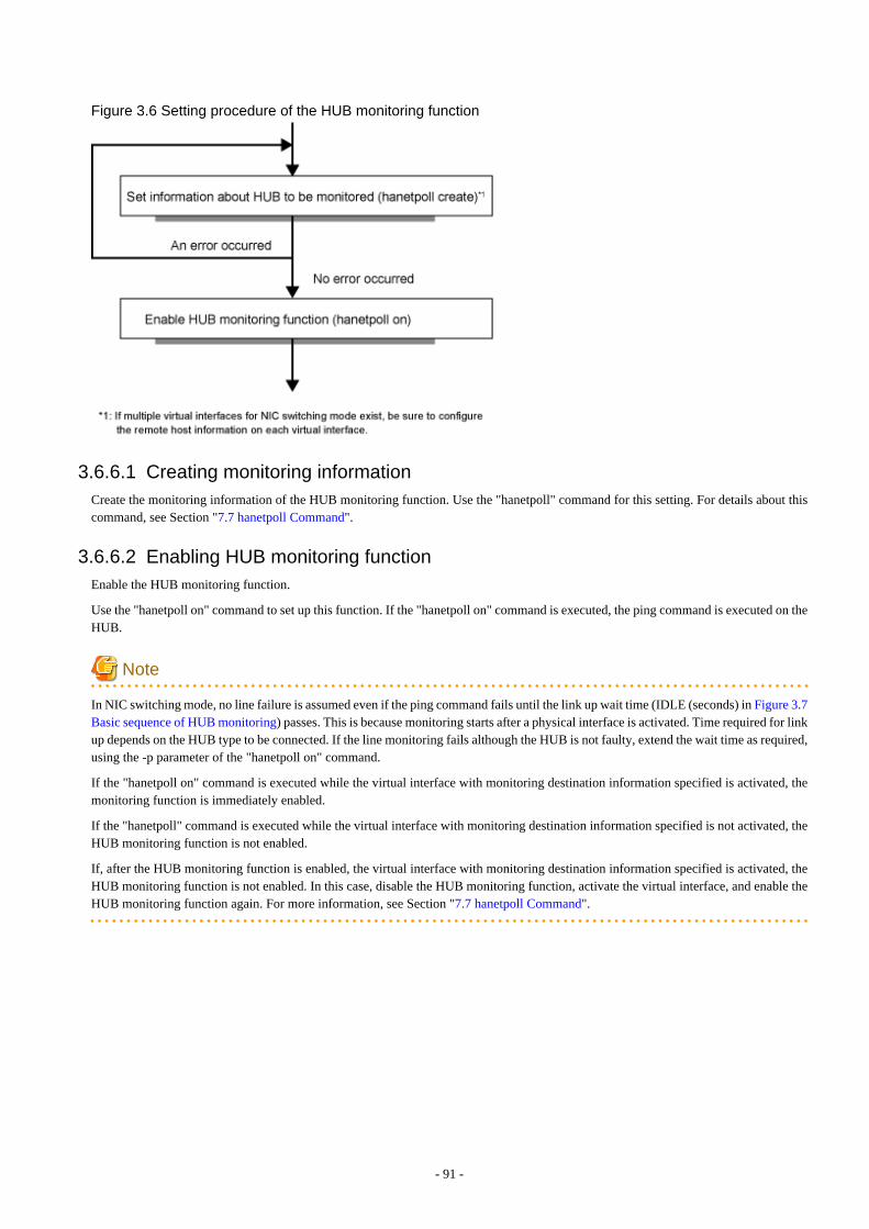
Figure 3.6 Setting procedure of the HUB monitoring function
3.6.6.1 Creating monitoring informationCreate the monitoring information of the HUB monitoring function. Use the "hanetpoll" command for this setting. For details about thiscommand, see Section "7.7 hanetpoll Command".
3.6.6.2 Enabling HUB monitoring functionEnable the HUB monitoring function.
Use the "hanetpoll on" command to set up this function. If the "hanetpoll on" command is executed, the ping command is executed on theHUB.
Note
In NIC switching mode, no line failure is assumed even if the ping command fails until the link up wait time (IDLE (seconds) in Figure 3.7Basic sequence of HUB monitoring) passes. This is because monitoring starts after a physical interface is activated. Time required for linkup depends on the HUB type to be connected. If the line monitoring fails although the HUB is not faulty, extend the wait time as required,using the -p parameter of the "hanetpoll on" command.
If the "hanetpoll on" command is executed while the virtual interface with monitoring destination information specified is activated, themonitoring function is immediately enabled.
If the "hanetpoll" command is executed while the virtual interface with monitoring destination information specified is not activated, theHUB monitoring function is not enabled.
If, after the HUB monitoring function is enabled, the virtual interface with monitoring destination information specified is activated, theHUB monitoring function is not enabled. In this case, disable the HUB monitoring function, activate the virtual interface, and enable theHUB monitoring function again. For more information, see Section "7.7 hanetpoll Command".
- 91 -
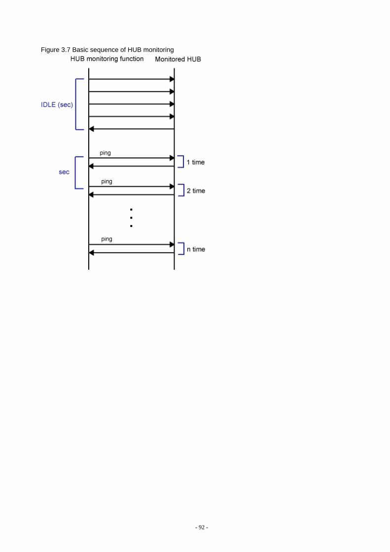
Figure 3.7 Basic sequence of HUB monitoring
- 92 -
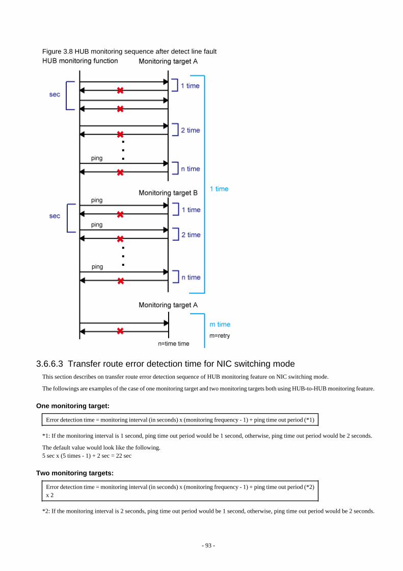
Figure 3.8 HUB monitoring sequence after detect line fault
3.6.6.3 Transfer route error detection time for NIC switching modeThis section describes on transfer route error detection sequence of HUB monitoring feature on NIC switching mode.
The followings are examples of the case of one monitoring target and two monitoring targets both using HUB-to-HUB monitoring feature.
One monitoring target:
Error detection time = monitoring interval (in seconds) x (monitoring frequency - 1) + ping time out period (*1)
*1: If the monitoring interval is 1 second, ping time out period would be 1 second, otherwise, ping time out period would be 2 seconds.
The default value would look like the following.5 sec x (5 times - 1) + 2 sec = 22 sec
Two monitoring targets:
Error detection time = monitoring interval (in seconds) x (monitoring frequency - 1) + ping time out period (*2)x 2
*2: If the monitoring interval is 2 seconds, ping time out period would be 1 second, otherwise, ping time out period would be 2 seconds.
- 93 -
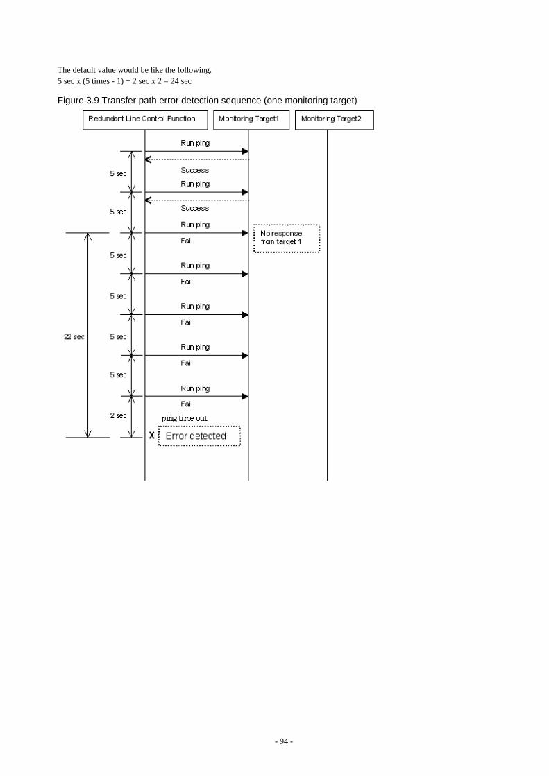
The default value would be like the following.5 sec x (5 times - 1) + 2 sec x 2 = 24 sec
Figure 3.9 Transfer path error detection sequence (one monitoring target)
- 94 -
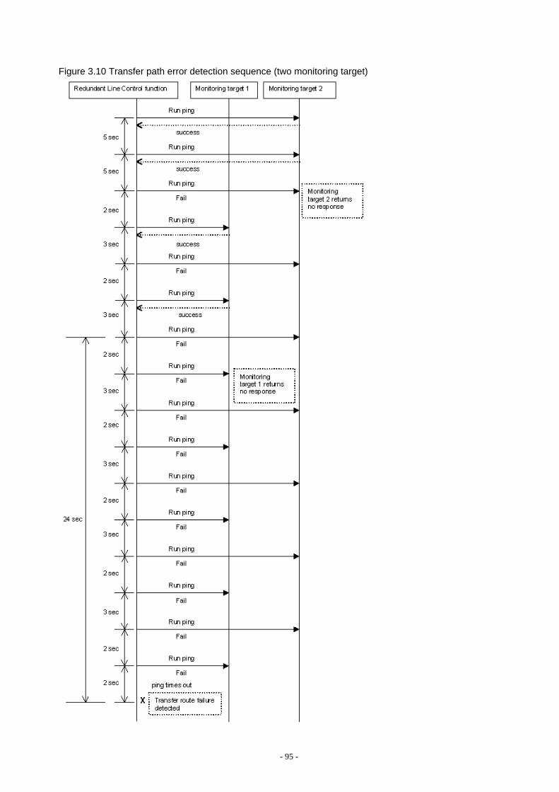
Figure 3.10 Transfer path error detection sequence (two monitoring target)
- 95 -
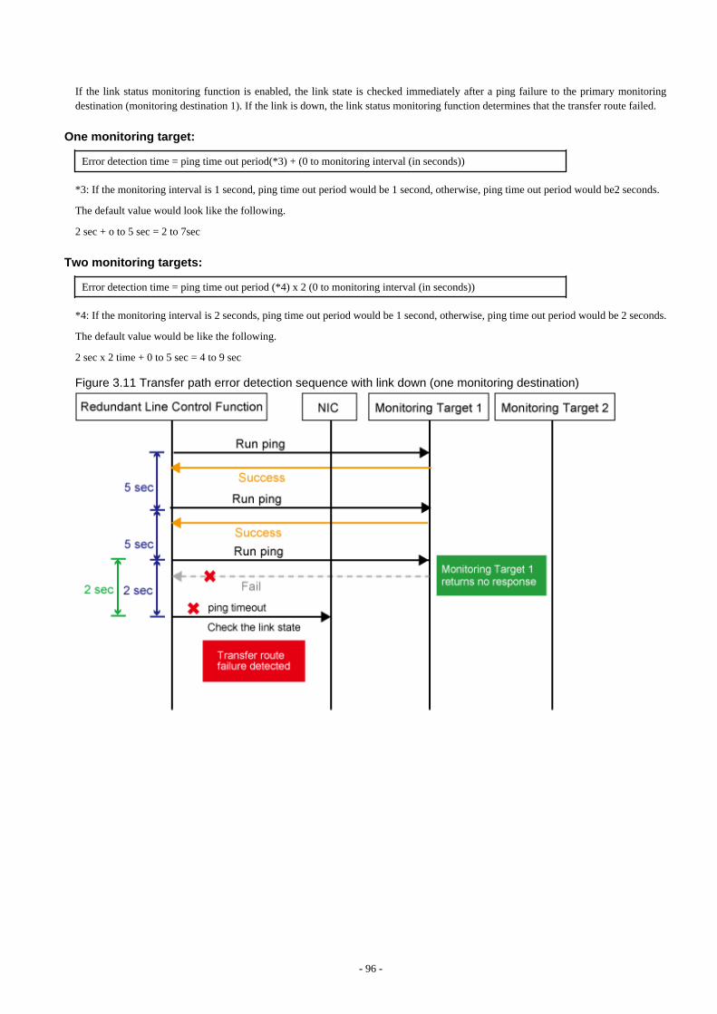
If the link status monitoring function is enabled, the link state is checked immediately after a ping failure to the primary monitoringdestination (monitoring destination 1). If the link is down, the link status monitoring function determines that the transfer route failed.
One monitoring target:
Error detection time = ping time out period(*3) + (0 to monitoring interval (in seconds))
*3: If the monitoring interval is 1 second, ping time out period would be 1 second, otherwise, ping time out period would be2 seconds.
The default value would look like the following.
2 sec + o to 5 sec = 2 to 7sec
Two monitoring targets:
Error detection time = ping time out period (*4) x 2 (0 to monitoring interval (in seconds))
*4: If the monitoring interval is 2 seconds, ping time out period would be 1 second, otherwise, ping time out period would be 2 seconds.
The default value would be like the following.
2 sec x 2 time + 0 to 5 sec = 4 to 9 sec
Figure 3.11 Transfer path error detection sequence with link down (one monitoring destination)
- 96 -
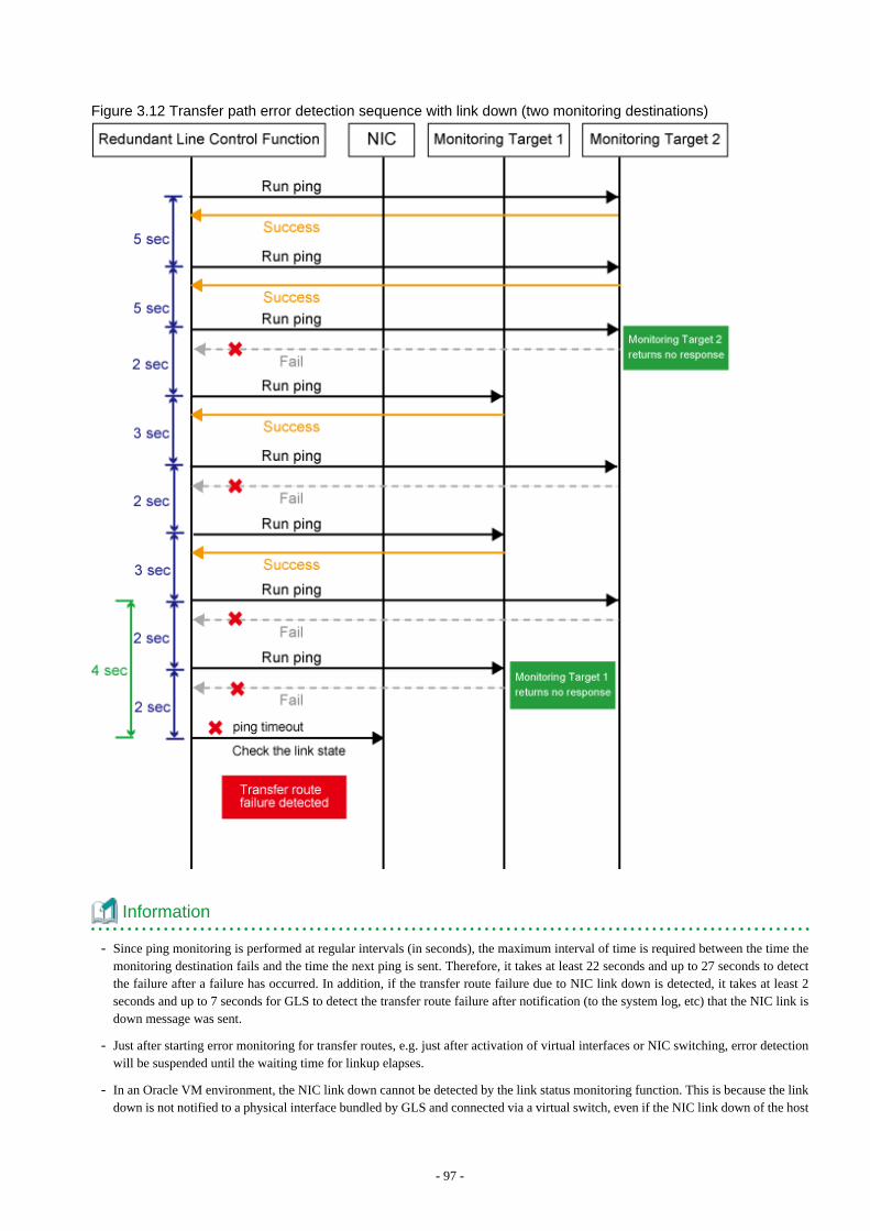
Figure 3.12 Transfer path error detection sequence with link down (two monitoring destinations)
Information
- Since ping monitoring is performed at regular intervals (in seconds), the maximum interval of time is required between the time themonitoring destination fails and the time the next ping is sent. Therefore, it takes at least 22 seconds and up to 27 seconds to detectthe failure after a failure has occurred. In addition, if the transfer route failure due to NIC link down is detected, it takes at least 2seconds and up to 7 seconds for GLS to detect the transfer route failure after notification (to the system log, etc) that the NIC link isdown message was sent.
- Just after starting error monitoring for transfer routes, e.g. just after activation of virtual interfaces or NIC switching, error detectionwill be suspended until the waiting time for linkup elapses.
- In an Oracle VM environment, the NIC link down cannot be detected by the link status monitoring function. This is because the linkdown is not notified to a physical interface bundled by GLS and connected via a virtual switch, even if the NIC link down of the host
- 97 -

domain is detected by the link status monitoring function. Therefore, the line will be switched after an error is detected by the HUBmonitoring function instead of by the link status monitoring function.
- If vnic is bundled by the NIC switching mode, the link down of a physical NIC cannot be detected with the link status monitoringfunction. This is because the link status of a physical NIC does not propagate to the vnic interface. Therefore, switching of transferpaths is not executed by the link status monitoring function, but is executed after detecting an error at HUB monitoring function.
3.6.7 Monitoring the remote hostSets a function to monitor if or not possible to communicate with a GS/SURE system (the other end of communication), that becomes theother end of communication when operating GS/SURE linkage mode. To set monitor-to, use the "hanetobserv" command. See "7.5hanetobserv Command" as to how to set it. To set an interval to monitor, use the "hanetpoll" command. See "7.7 hanetpoll Command" asto how to set it.
Note
It is necessary to set GS/SURE linkage mode (the operation mode is "c") before executing this setting.
If the local system is running on a clustered system, it switches a node when GS/SURE system (remote host) stops. During this process,if no response is returned from any of the defined monitored remote system by executing "hanetobserv" command, it is recognized as alocal NIC failure and it switches the node. Moreover, even though all the GS/SURE system (remote host) stops operating, all monitoredremote system does not return responses, and there occurred an unnecessary switching. To avoid this, it is possible to interoperateoperational node and standby node to monitor network failures. So that if all the remote system stops operating, it does not mistakenlyswitch the node.
If operating the cluster, use the "hanetobserv" command to monitor from both operational node and standby command. Keep in mind thatsince it is necessary to identify the remote node from both operational and standby node, a take-over IP address must be used for a virtualIP address.
3.6.7.1 Transfer route error detection time in GS/SURE linkage modeThis section describes the transfer route error detection sequence.
In GS/SURE linkage mode, issue the ping command for the real IP address of a target that you set with the remote host monitoring functionand for the IP addresses of other nodes in the cluster. The time it takes for an error to be detected is as follows:
Error detection time:
Error detection time = monitoring interval (in seconds) x (monitoring frequency - 1) + ping time out period (*1)
*1: If the monitoring interval is 1 second, ping time out period would be 1 second, otherwise, ping time out period would be 2 seconds.
The default value would look like the following:
5 sec x (5 times - 1) + 2 sec = 22 sec
Note that if the target detects an error first, it will determine that an error has occurred on the transfer route without waiting for the errordetection by ping monitoring.
The settings for the error detection time can be changed by using the "hanetpoll" command. For more details on how to make settings, see"7.7 hanetpoll Command".
- 98 -
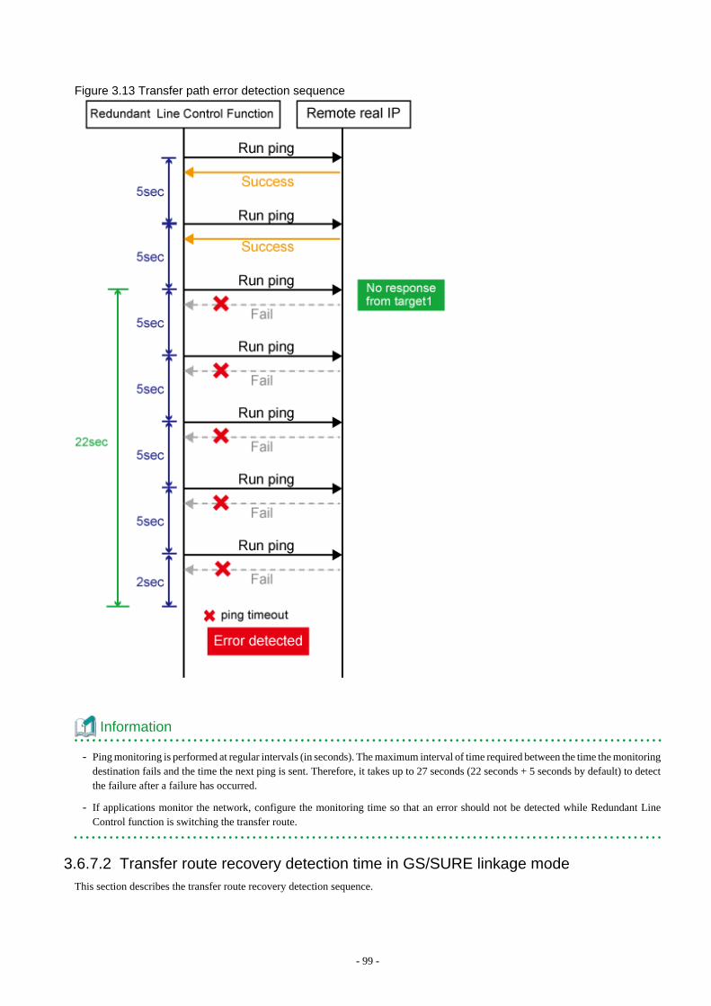
Figure 3.13 Transfer path error detection sequence
Information
- Ping monitoring is performed at regular intervals (in seconds). The maximum interval of time required between the time the monitoringdestination fails and the time the next ping is sent. Therefore, it takes up to 27 seconds (22 seconds + 5 seconds by default) to detectthe failure after a failure has occurred.
- If applications monitor the network, configure the monitoring time so that an error should not be detected while Redundant LineControl function is switching the transfer route.
3.6.7.2 Transfer route recovery detection time in GS/SURE linkage modeThis section describes the transfer route recovery detection sequence.
- 99 -

In GS/SURE linkage mode, issue the ping command for the real IP address of the target that you set with the remote host monitoringfunction. After the transfer route error has been detected, Redundant Line Control function performs recovery monitoring by ping tomonitor the state of the recovery of transfer route. The time it takes for recovery to be detected is as follows:
Recovery detection time:
Recovery detection time = recovery monitoring interval (in seconds)
Note that if the target detects the recovery first, it will determine that the transfer route has recovered without waiting for the recoverydetection by ping monitoring.
The settings for the error detection time can be changed by using the "hanetpoll" command. For more details on how to make settings, see"7.7 hanetpoll Command".
Figure 3.14 Transfer path recovery detection sequence
3.6.8 Standby patrol function
3.6.8.1 Setting what to be monitoredIt is possible to set a function to monitor the state of a standby interface in non-activated condition when operating NIC switching mode.It is also possible to set an Automatic failback function when a primary interface recovered using a standby patrol function. Use the"hanetconfig" command to set it. See Section "7.1 hanetconfig Command" as to how to set it.
- 100 -
Note
It is necessary to set a virtual interface of NIC switching mode (an operation mode is either "d" or "e") before this setting.
3.6.8.2 Setting monitoring intervalSet the monitoring interval for the standby NIC. Use the "hanetparam" command for this setting. For details about this command, seeSection "7.6 hanetparam Command".
3.6.8.3 Setting error monitoring intervalSet the monitoring failure count for the standby NIC before a message is output. Use the "hanetparam" command for this setting. Fordetails about this command, see Section "7.6 hanetparam Command".
3.6.9 Setting dynamic addition/deletion/switching function of physicalinterfaces
3.6.9.1 Dynamic addition of physical interfacesIn Fast switching mode and GS/SURE linkage mode, it is possible to add an actual interface to be redundant while keeping a virtualinterface activated. This is called "Dynamic addition of an actual interface". To add dynamically, use the "hanetnic add" command. See"7.9 hanetnic Command" as to how to set.
3.6.9.2 Dynamic deletion of physical interfacesIn Fast switching mode and GS/SURE linkage mode, it is possible to delete a redundant actual interface while keeping a virtual interfaceactivated. This is called "Dynamic deletion of an actual interface". To delete dynamically, use the "hanetnic delete" command. See "7.9hanetnic Command" as to how to set.
3.6.9.3 Dynamic switching of physical interfacesIn NIC switching mode, it is possible to switch a using actual interface from an operation system to a standby system while keeping theoperation state. This is called "dynamic switching of an actual interface". To change dynamically, use the "hanetnic change" command.See "7.9 hanetnic Command" as to how to set.
3.6.10 Setting User command execution functionA user-defined command can be executed at a specific timing. For information on execution timing, see "2.2.11 User command executionfunction". In NIC switching mode, this function can be used to flush an ARP table, change the interface status, and change the MTUlength, etc. In GS/SURE linkage mode, this function can be used to send a signal to a specific process, etc. The following settings mustbe made to execute a user command. See the sample files for information on creating a script file appropriate for a user's environment.
Sample file for NIC switching mode
- /etc/opt/FJSVhanet/script/interface/sha.interface.sam (When activating or deactivating an IP address)
- /etc/opt/FJSVhanet/script/failover/sha.failover.sam (When detected an error in a transfer route)
- /etc/opt/FJSVhanet/script/patrol/sha.patrol.sam (When detected a standby patrol error or recovery)
Sample file for GS/SURE linkage mode
- /etc/opt/FJSVhanet/script/host/host.sam
Sample file of the service for Redundant Line Control function
- /etc/opt/FJSVhanet/script/service.sh.sam
- /etc/opt/FJSVhanet/script/system/monitor.sam
- 101 -
[Setup files]
The storage destination and file name of a setup file varies depending on the type and name of a virtual interface.
Setup file for NIC switching mode
- /etc/opt/FJSVhanet/script/interface/shaX (When activating or deactivating an IP address)
- /etc/opt/FJSVhanet/script/failover/shaX (When detected an error in a transfer route)
- /etc/opt/FJSVhanet/script/patrol/shaY (When detected a standby patrol error or recovery)
* shaX is the created virtual interface name for NIC switching mode.
* shaY is the created virtual interface name of the standby patrol for NIC switching mode.
Setup file for GS/SURE linkage mode
- /etc/opt/FJSVhanet/script/host/hostIP
* hostIP is the host name or IP address of the virtual interface of the communication target.
However, pay attention to the following point when using the host name:
If the same IP address is defined to two or more host names in the /etc/inet/hosts file, use the host name which is defined in thebeginning of the hosts file.
Setup file of the service for Redundant Line Control function
- /etc/opt/FJSVhanet/script/service.sh
- /etc/opt/FJSVhanet/script/system/monitor
Note
- Do not call the operational command for redundancy line control function in the script file.
- The commands executed in the script file do not output messages to the standard output. When checking for the contents of the outputmessages, use the "logger(1)" command of the operating system to output the messages to syslog.
- In a clustered system, the script for NIC switching mode of activating or deactivating IP addresses is executed only by active node.It will not run for standby node.
3.6.10.1 Settings for NIC switching modeThe following shows the script file call format and the definition file sample for the operation in NIC switching mode.
(1) When activated or deactivated an IP address
[Script file call format]
/bin/sh shaX param1 param2 param3 param4
param1
activate: Activation of a takeover IP addressinactivate: Inactivation of a takeover IP addresscreate: Activation of a physical NIC (logical IP takeover only)delete: Inactivation of a physical NIC (logical IP takeover only)
param2
before: Before activation or deactivationafter: After activation or deactivation
param3
ifname: Physical interface name
- 102 -

param4
inet6: Address family (IPv6 only)* No param4 for IPv4.
[Definition file sample] #!/bin/sh## All Rights Reserved, Copyright (c) FUJITSU LIMITED 2011##ident "%W% %G% %U% - FUJITSU"#
## Control interface for HA-Net#
## Params## $1 activate or inactivate or create or delete# $2 before or after# $3 physical interface name# $4 address family (IPv6 only)#
## Set Params#
INTERFACE=$3#IP_ADDR1="xx.xx.xx.xx"#IP_ADDR2="yy.yy.yy.yy" #MAC_ADDR1="xx:xx:xx:xx:xx:xx"#MAC_ADDR2="yy:yy:yy:yy:yy:yy"
cace $# in3) ADDRESS_FAMILY="inet";;4) if [ $4 = "inet6" ] then ADDRESS_FAMILY="inet6" else ADDRESS_FAMILY="unknown" fi;;*) ADDRESS_FAMILY="unknown";;esac
if [ $ADDRESS_FAMILY = "inet" ]then
case "$1" in'activate')
## Activate interface#
- 103 -

case "$2" in'before')## script before activate interface#
# logger -p daemon.notice "execute script before activate interface on" $INTERFACE#if [ ! $INTERFACE = "hmeX" ]#then# ifconfig $INTERFACE ether $MAC_ADDR1#else# ifconfig $INTERFACE ether $MAC_ADDR2#fi;;
'after')## script after activate interface#
# logger -p daemon.notice "execute script after activate interface on" $INTERFACE
#if [ ! $INTERFACE = "hmeX" ]#then# arp -d $IP_ADDR1# ping $IP_ADDR2 2#else# arp -d $IP_ADDR2# ping $IP_ADDR1 2#fi
;;
*) ;;esac
;;
'inactivate')## inactivate interface#
case "$2" in'before')## script before inactivate interface#
# logger -p daemon.notice "execute script before inactivate interface on" $INTERFACE;;
'after')## script after inactivate interface#
# logger -p daemon.notice "execute script after inactivate interface on" $INTERFACE
- 104 -
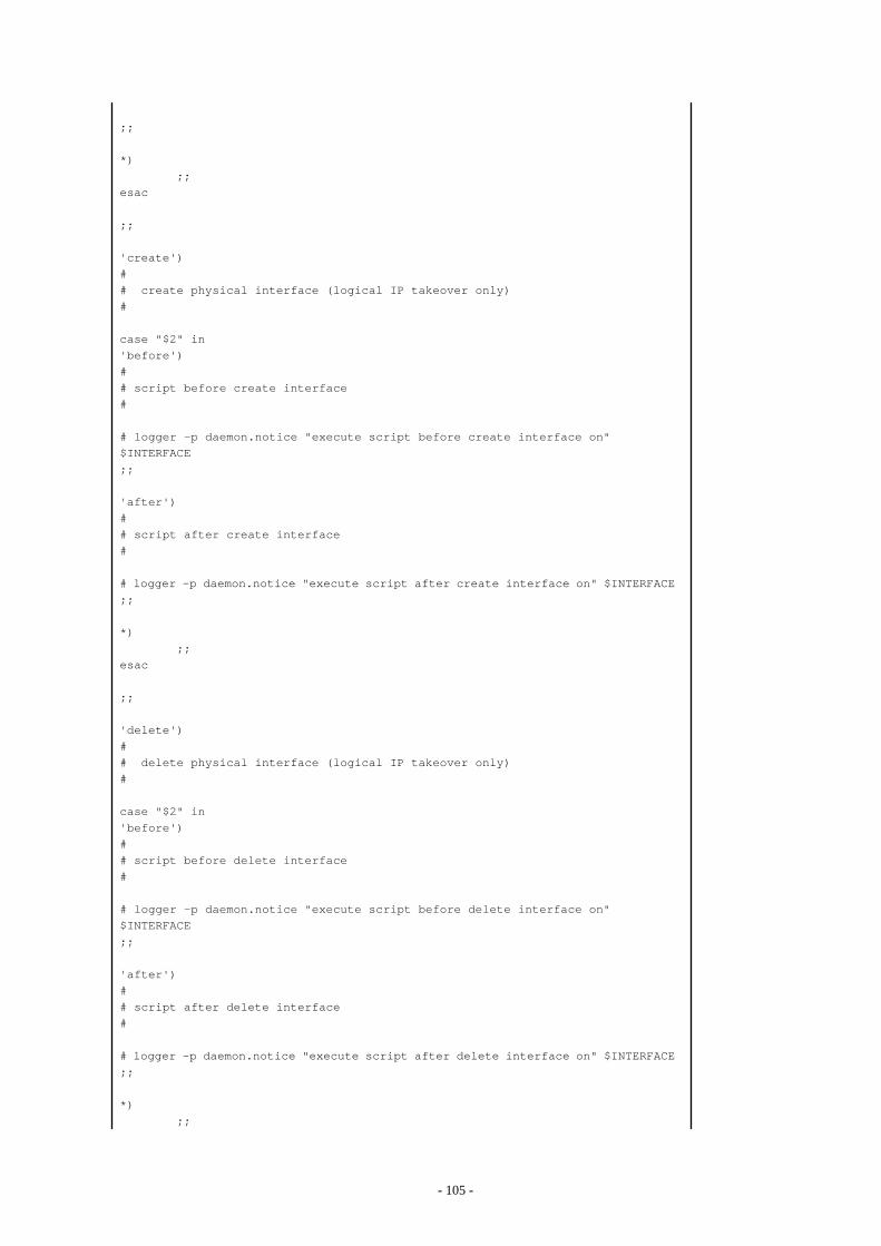
;;
*) ;;esac
;;
'create')## create physical interface (logical IP takeover only)#
case "$2" in'before')## script before create interface#
# logger -p daemon.notice "execute script before create interface on" $INTERFACE;;
'after')## script after create interface#
# logger -p daemon.notice "execute script after create interface on" $INTERFACE;;
*) ;;esac
;;
'delete')## delete physical interface (logical IP takeover only)#
case "$2" in'before')## script before delete interface#
# logger -p daemon.notice "execute script before delete interface on" $INTERFACE;;
'after')## script after delete interface#
# logger -p daemon.notice "execute script after delete interface on" $INTERFACE;;
*) ;;
- 105 -
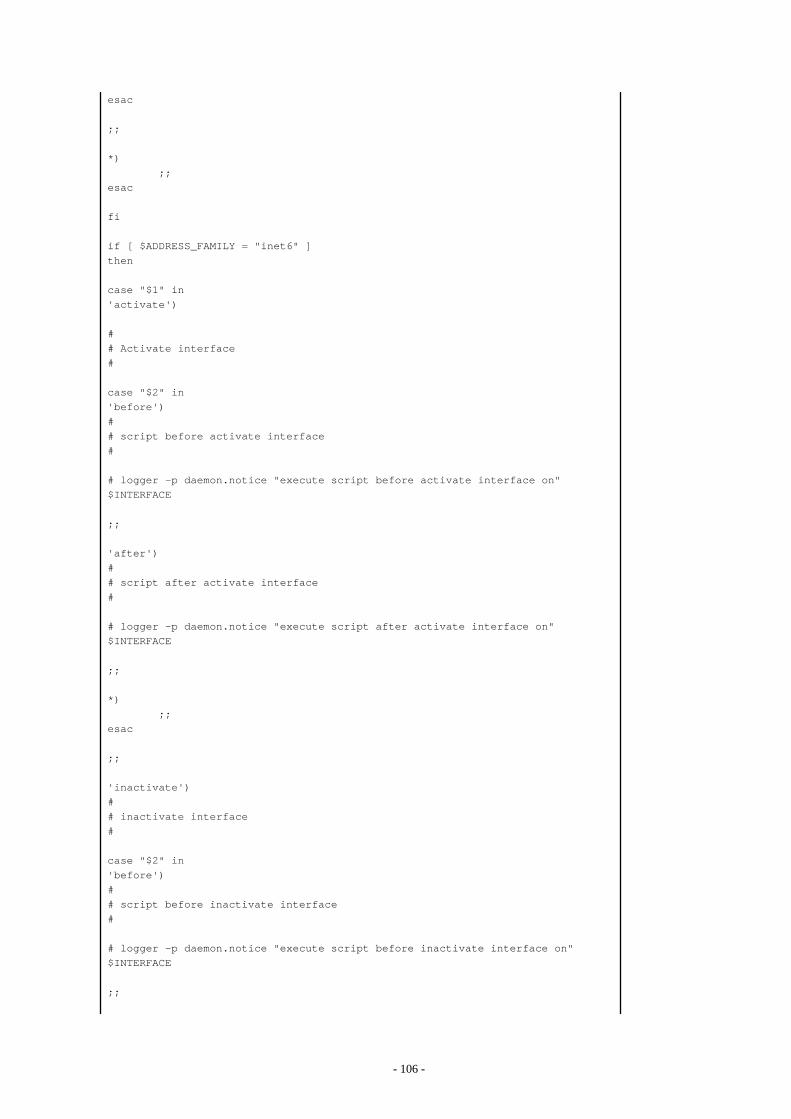
esac
;;
*) ;;esac
fi
if [ $ADDRESS_FAMILY = "inet6" ]then
case "$1" in'activate')
## Activate interface#
case "$2" in'before')## script before activate interface#
# logger -p daemon.notice "execute script before activate interface on" $INTERFACE
;;
'after')## script after activate interface#
# logger -p daemon.notice "execute script after activate interface on" $INTERFACE
;;
*) ;;esac
;;
'inactivate')## inactivate interface#
case "$2" in'before')## script before inactivate interface#
# logger -p daemon.notice "execute script before inactivate interface on" $INTERFACE
;;
- 106 -
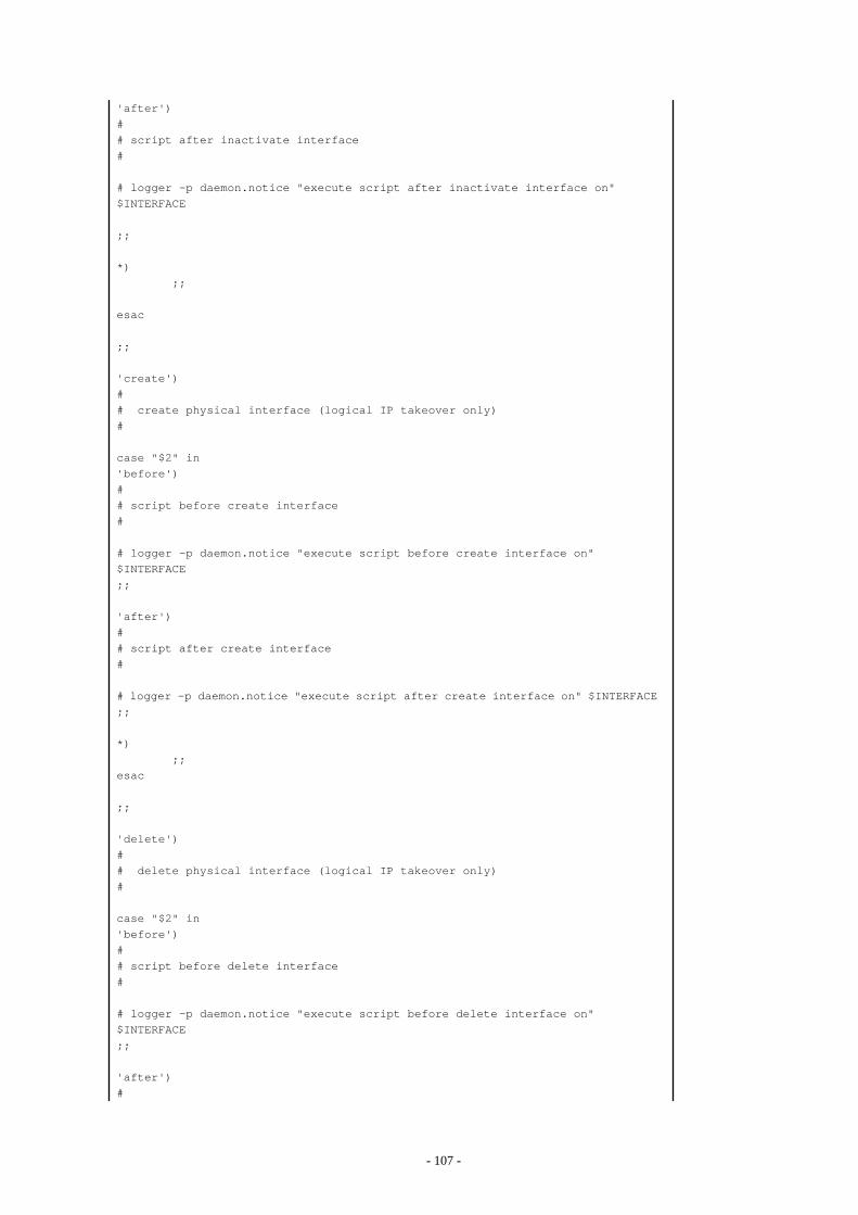
'after')## script after inactivate interface#
# logger -p daemon.notice "execute script after inactivate interface on" $INTERFACE
;;
*) ;;
esac
;;
'create')## create physical interface (logical IP takeover only)#
case "$2" in'before')## script before create interface#
# logger -p daemon.notice "execute script before create interface on" $INTERFACE;;
'after')## script after create interface#
# logger -p daemon.notice "execute script after create interface on" $INTERFACE;;
*) ;;esac
;;
'delete')## delete physical interface (logical IP takeover only)#
case "$2" in'before')## script before delete interface#
# logger -p daemon.notice "execute script before delete interface on" $INTERFACE;;
'after')#
- 107 -
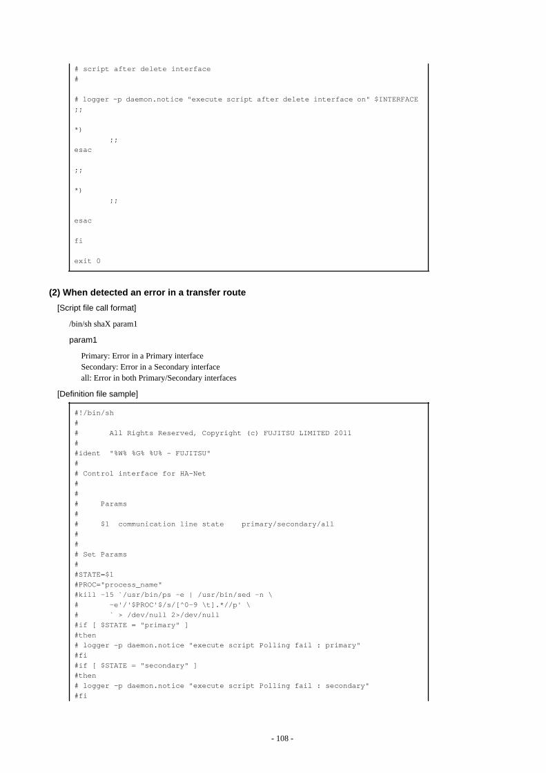
# script after delete interface#
# logger -p daemon.notice "execute script after delete interface on" $INTERFACE;;
*) ;;esac
;;
*) ;;
esac
fi
exit 0
(2) When detected an error in a transfer route
[Script file call format]
/bin/sh shaX param1
param1
Primary: Error in a Primary interfaceSecondary: Error in a Secondary interfaceall: Error in both Primary/Secondary interfaces
[Definition file sample] #!/bin/sh## All Rights Reserved, Copyright (c) FUJITSU LIMITED 2011##ident "%W% %G% %U% - FUJITSU"## Control interface for HA-Net### Params## $1 communication line state primary/secondary/all### Set Params##STATE=$1#PROC="process_name"#kill -15 `/usr/bin/ps -e | /usr/bin/sed -n \# -e'/'$PROC'$/s/[^0-9 \t].*//p' \# ` > /dev/null 2>/dev/null#if [ $STATE = "primary" ]#then# logger -p daemon.notice "execute script Polling fail : primary"#fi#if [ $STATE = "secondary" ]#then# logger -p daemon.notice "execute script Polling fail : secondary"#fi
- 108 -
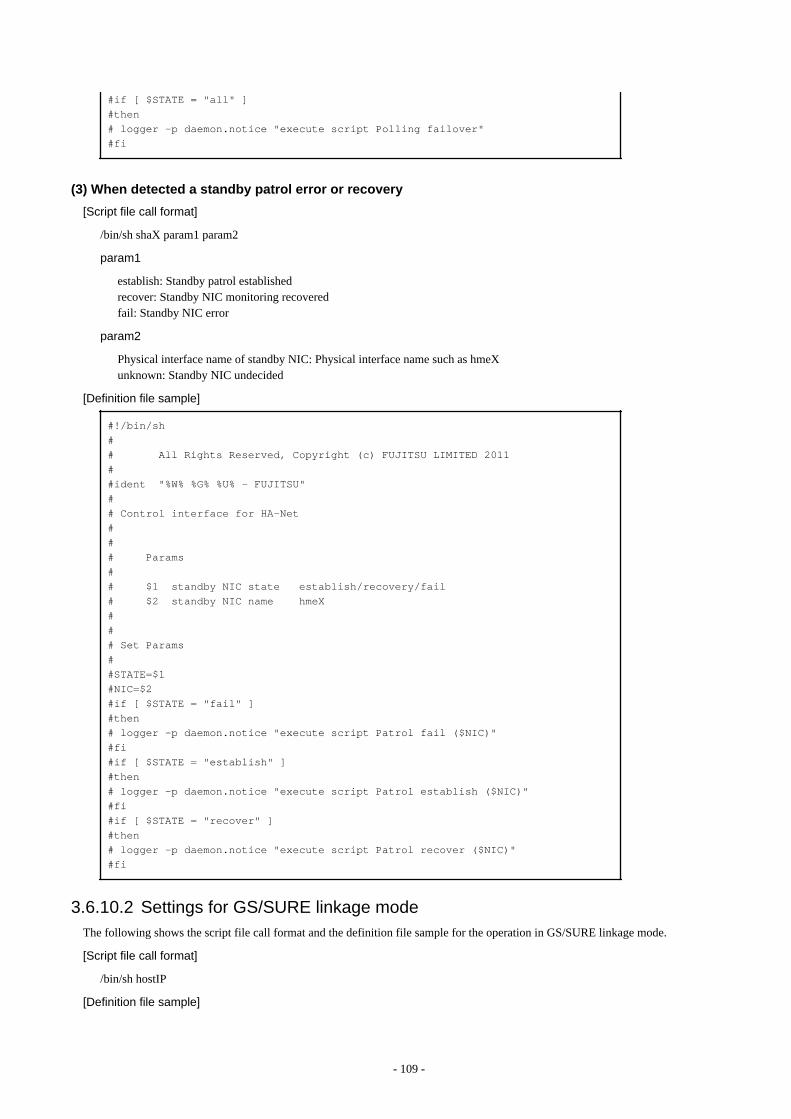
#if [ $STATE = "all" ]#then# logger -p daemon.notice "execute script Polling failover"#fi
(3) When detected a standby patrol error or recovery
[Script file call format]
/bin/sh shaX param1 param2
param1
establish: Standby patrol establishedrecover: Standby NIC monitoring recoveredfail: Standby NIC error
param2
Physical interface name of standby NIC: Physical interface name such as hmeXunknown: Standby NIC undecided
[Definition file sample] #!/bin/sh## All Rights Reserved, Copyright (c) FUJITSU LIMITED 2011##ident "%W% %G% %U% - FUJITSU"## Control interface for HA-Net### Params## $1 standby NIC state establish/recovery/fail# $2 standby NIC name hmeX### Set Params##STATE=$1#NIC=$2#if [ $STATE = "fail" ]#then# logger -p daemon.notice "execute script Patrol fail ($NIC)"#fi#if [ $STATE = "establish" ]#then# logger -p daemon.notice "execute script Patrol establish ($NIC)"#fi#if [ $STATE = "recover" ]#then# logger -p daemon.notice "execute script Patrol recover ($NIC)"#fi
3.6.10.2 Settings for GS/SURE linkage modeThe following shows the script file call format and the definition file sample for the operation in GS/SURE linkage mode.
[Script file call format]
/bin/sh hostIP
[Definition file sample]
- 109 -
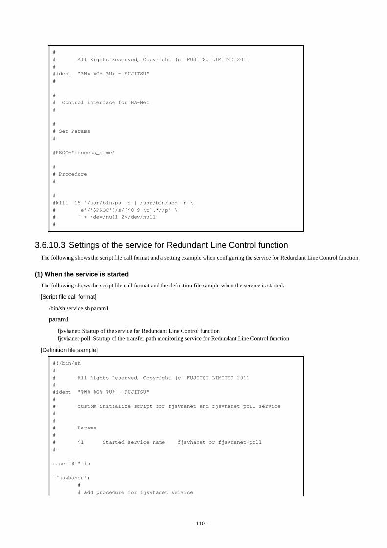
## All Rights Reserved, Copyright (c) FUJITSU LIMITED 2011##ident "%W% %G% %U% - FUJITSU"#
## Control interface for HA-Net#
## Set Params#
#PROC="process_name"
## Procedure#
##kill -15 `/usr/bin/ps -e | /usr/bin/sed -n \# -e'/'$PROC'$/s/[^0-9 \t].*//p' \# ` > /dev/null 2>/dev/null#
3.6.10.3 Settings of the service for Redundant Line Control functionThe following shows the script file call format and a setting example when configuring the service for Redundant Line Control function.
(1) When the service is started
The following shows the script file call format and the definition file sample when the service is started.
[Script file call format]
/bin/sh service.sh param1
param1
fjsvhanet: Startup of the service for Redundant Line Control functionfjsvhanet-poll: Startup of the transfer path monitoring service for Redundant Line Control function
[Definition file sample] #!/bin/sh## All Rights Reserved, Copyright (c) FUJITSU LIMITED 2011##ident "%W% %G% %U% - FUJITSU"## custom initialize script for fjsvhanet and fjsvhanet-poll service### Params## $1 Started service name fjsvhanet or fjsvhanet-poll#
case "$1" in
'fjsvhanet') # # add procedure for fjsvhanet service
- 110 -
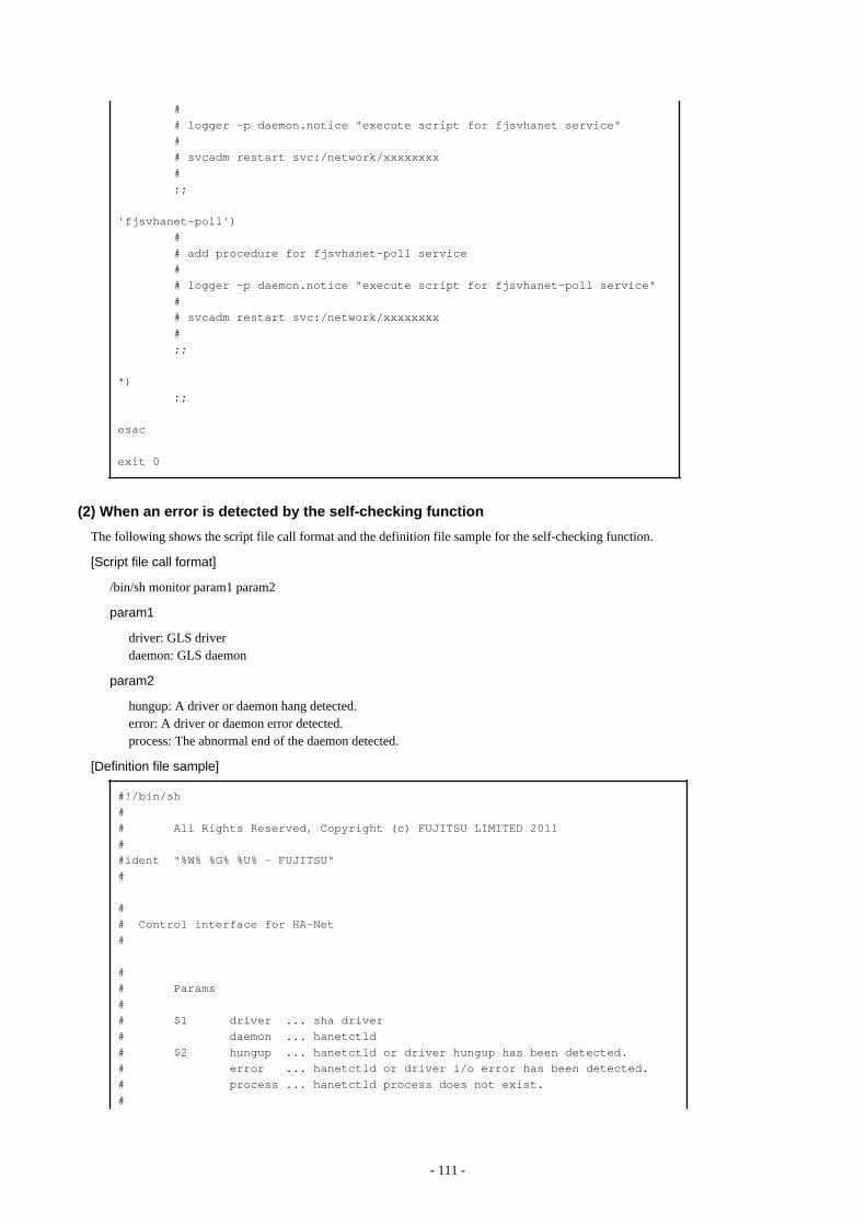
# # logger -p daemon.notice "execute script for fjsvhanet service" # # svcadm restart svc:/network/xxxxxxxx # ;;
'fjsvhanet-poll') # # add procedure for fjsvhanet-poll service # # logger -p daemon.notice "execute script for fjsvhanet-poll service" # # svcadm restart svc:/network/xxxxxxxx # ;;
*) ;;
esac
exit 0
(2) When an error is detected by the self-checking function
The following shows the script file call format and the definition file sample for the self-checking function.
[Script file call format]
/bin/sh monitor param1 param2
param1
driver: GLS driverdaemon: GLS daemon
param2
hungup: A driver or daemon hang detected.error: A driver or daemon error detected.process: The abnormal end of the daemon detected.
[Definition file sample] #!/bin/sh## All Rights Reserved, Copyright (c) FUJITSU LIMITED 2011##ident "%W% %G% %U% - FUJITSU"#
## Control interface for HA-Net#
## Params## $1 driver ... sha driver# daemon ... hanetctld# $2 hungup ... hanetctld or driver hungup has been detected.# error ... hanetctld or driver i/o error has been detected.# process ... hanetctld process does not exist.#
- 111 -
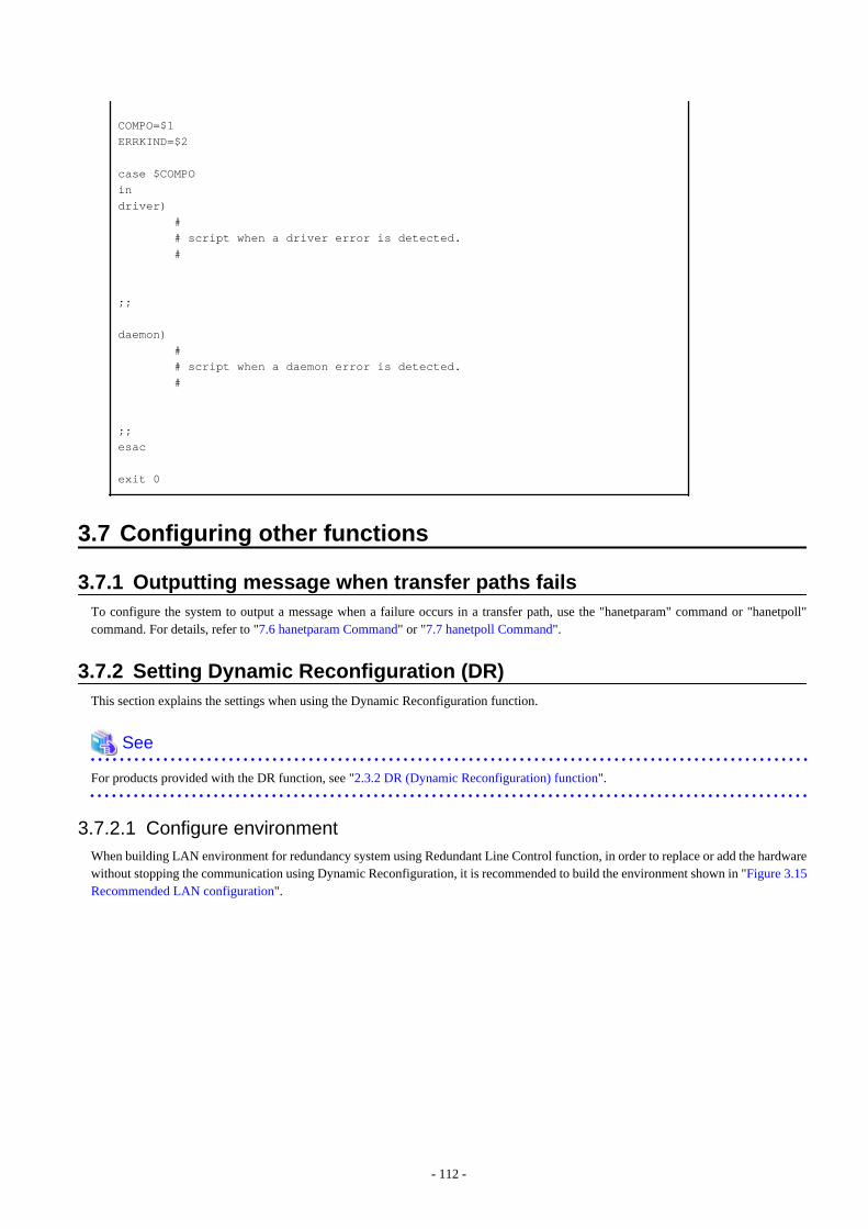
COMPO=$1ERRKIND=$2
case $COMPOindriver) # # script when a driver error is detected. #
;;
daemon) # # script when a daemon error is detected. #
;;esac
exit 0
3.7 Configuring other functions
3.7.1 Outputting message when transfer paths failsTo configure the system to output a message when a failure occurs in a transfer path, use the "hanetparam" command or "hanetpoll"command. For details, refer to "7.6 hanetparam Command" or "7.7 hanetpoll Command".
3.7.2 Setting Dynamic Reconfiguration (DR)This section explains the settings when using the Dynamic Reconfiguration function.
See
For products provided with the DR function, see "2.3.2 DR (Dynamic Reconfiguration) function".
3.7.2.1 Configure environmentWhen building LAN environment for redundancy system using Redundant Line Control function, in order to replace or add the hardwarewithout stopping the communication using Dynamic Reconfiguration, it is recommended to build the environment shown in "Figure 3.15Recommended LAN configuration".
- 112 -
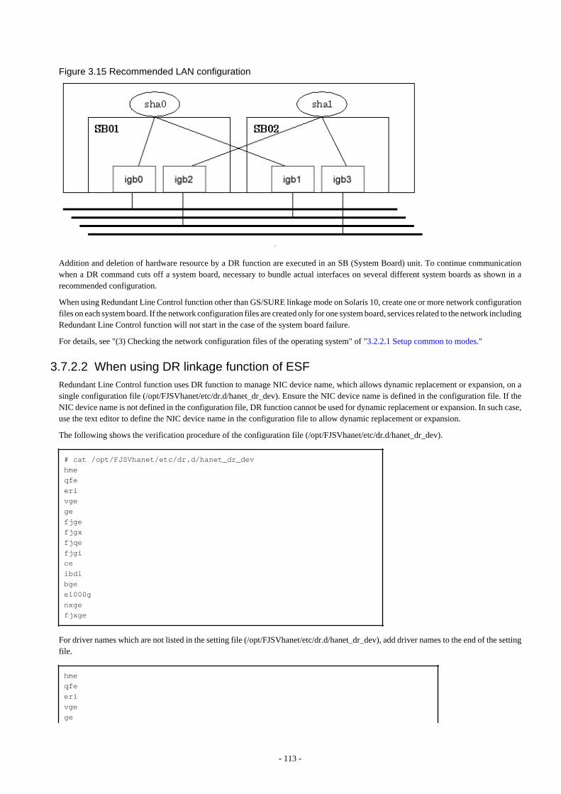
Figure 3.15 Recommended LAN configuration
Addition and deletion of hardware resource by a DR function are executed in an SB (System Board) unit. To continue communicationwhen a DR command cuts off a system board, necessary to bundle actual interfaces on several different system boards as shown in arecommended configuration.
When using Redundant Line Control function other than GS/SURE linkage mode on Solaris 10, create one or more network configurationfiles on each system board. If the network configuration files are created only for one system board, services related to the network includingRedundant Line Control function will not start in the case of the system board failure.
For details, see "(3) Checking the network configuration files of the operating system" of "3.2.2.1 Setup common to modes."
3.7.2.2 When using DR linkage function of ESFRedundant Line Control function uses DR function to manage NIC device name, which allows dynamic replacement or expansion, on asingle configuration file (/opt/FJSVhanet/etc/dr.d/hanet_dr_dev). Ensure the NIC device name is defined in the configuration file. If theNIC device name is not defined in the configuration file, DR function cannot be used for dynamic replacement or expansion. In such case,use the text editor to define the NIC device name in the configuration file to allow dynamic replacement or expansion.
The following shows the verification procedure of the configuration file (/opt/FJSVhanet/etc/dr.d/hanet_dr_dev).
# cat /opt/FJSVhanet/etc/dr.d/hanet_dr_devhmeqfeerivgegefjgefjgxfjqefjgiceibdlbgee1000gnxgefjxge
For driver names which are not listed in the setting file (/opt/FJSVhanet/etc/dr.d/hanet_dr_dev), add driver names to the end of the settingfile.
hmeqfeerivgege
- 113 -
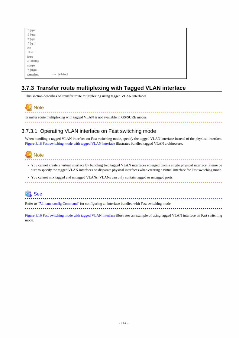
fjgefjgxfjqefjgiceibdlbge e1000g nxgefjxgenewdev <- Added
3.7.3 Transfer route multiplexing with Tagged VLAN interfaceThis section describes on transfer route multiplexing using tagged VLAN interfaces.
Note
Transfer route multiplexing with tagged VLAN is not available in GS/SURE modes.
3.7.3.1 Operating VLAN interface on Fast switching modeWhen bundling a tagged VLAN interface on Fast switching mode, specify the tagged VLAN interface instead of the physical interface.Figure 3.16 Fast switching mode with tagged VLAN interface illustrates bundled tagged VLAN architecture.
Note
- You cannot create a virtual interface by bundling two tagged VLAN interfaces emerged from a single physical interface. Please besure to specify the tagged VLAN interfaces on disparate physical interfaces when creating a virtual interface for Fast switching mode.
- You cannot mix tagged and untagged VLANs. VLANs can only contain tagged or untagged ports.
See
Refer to "7.1 hanetconfig Command" for configuring an interface bundled with Fast switching mode.
Figure 3.16 Fast switching mode with tagged VLAN interface illustrates an example of using tagged VLAN interface on Fast switchingmode.
- 114 -
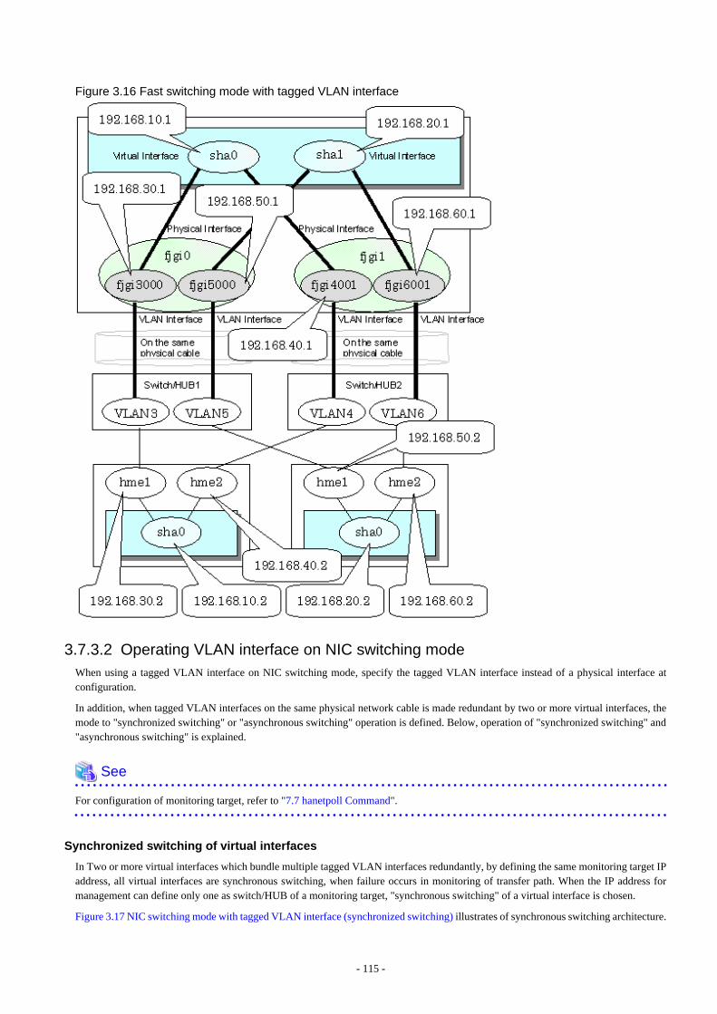
Figure 3.16 Fast switching mode with tagged VLAN interface
3.7.3.2 Operating VLAN interface on NIC switching modeWhen using a tagged VLAN interface on NIC switching mode, specify the tagged VLAN interface instead of a physical interface atconfiguration.
In addition, when tagged VLAN interfaces on the same physical network cable is made redundant by two or more virtual interfaces, themode to "synchronized switching" or "asynchronous switching" operation is defined. Below, operation of "synchronized switching" and"asynchronous switching" is explained.
See
For configuration of monitoring target, refer to "7.7 hanetpoll Command".
Synchronized switching of virtual interfaces
In Two or more virtual interfaces which bundle multiple tagged VLAN interfaces redundantly, by defining the same monitoring target IPaddress, all virtual interfaces are synchronous switching, when failure occurs in monitoring of transfer path. When the IP address formanagement can define only one as switch/HUB of a monitoring target, "synchronous switching" of a virtual interface is chosen.
Figure 3.17 NIC switching mode with tagged VLAN interface (synchronized switching) illustrates of synchronous switching architecture.
- 115 -
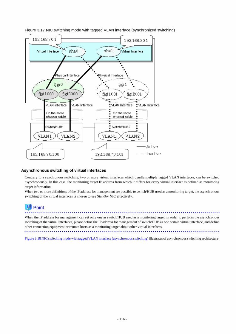
Figure 3.17 NIC switching mode with tagged VLAN interface (synchronized switching)
Asynchronous switching of virtual interfaces
Contrary to a synchronous switching, two or more virtual interfaces which bundle multiple tagged VLAN interfaces, can be switchedasynchronously. In this case, the monitoring target IP address from which it differs for every virtual interface is defined as monitoringtarget information.When two or more definitions of the IP address for management are possible to switch/HUB used as a monitoring target, the asynchronousswitching of the virtual interfaces is chosen to use Standby NIC effectively.
Point
When the IP address for management can set only one as switch/HUB used as a monitoring target, in order to perform the asynchronousswitching of the virtual interfaces, please define the IP address for management of switch/HUB as one certain virtual interface, and defineother connection equipment or remote hosts as a monitoring target about other virtual interfaces.
Figure 3.18 NIC switching mode with tagged VLAN interface (asynchronous switching) illustrates of asynchronous switching architecture.
- 116 -
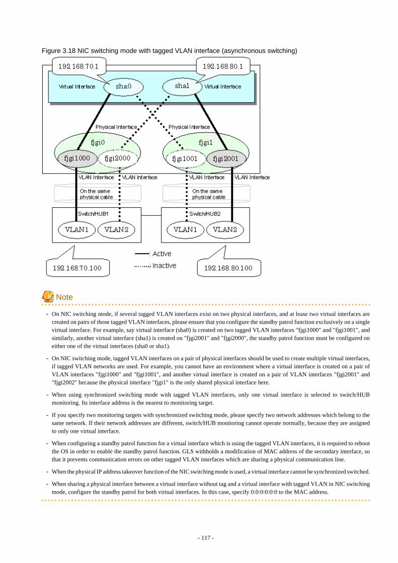
Figure 3.18 NIC switching mode with tagged VLAN interface (asynchronous switching)
Note
- On NIC switching mode, if several tagged VLAN interfaces exist on two physical interfaces, and at lease two virtual interfaces arecreated on pairs of those tagged VLAN interfaces, please ensure that you configure the standby patrol function exclusively on a singlevirtual interface. For example, say virtual interface (sha0) is created on two tagged VLAN interfaces "fjgi1000" and "fjgi1001", andsimilarly, another virtual interface (sha1) is created on "fjgi2001" and "fjgi2000", the standby patrol function must be configured oneither one of the virtual interfaces (sha0 or sha1).
- On NIC switching mode, tagged VLAN interfaces on a pair of physical interfaces should be used to create multiple virtual interfaces,if tagged VLAN networks are used. For example, you cannot have an environment where a virtual interface is created on a pair ofVLAN interfaces "fjgi1000" and "fjgi1001", and another virtual interface is created on a pair of VLAN interfaces "fjgi2001" and"fjgi2002" because the physical interface "fjgi1" is the only shared physical interface here.
- When using synchronized switching mode with tagged VLAN interfaces, only one virtual interface is selected to switch/HUBmonitoring. Its interface address is the nearest to monitoring target.
- If you specify two monitoring targets with synchronized switching mode, please specify two network addresses which belong to thesame network. If their network addresses are different, switch/HUB monitoring cannot operate normally, because they are assignedto only one virtual interface.
- When configuring a standby patrol function for a virtual interface which is using the tagged VLAN interfaces, it is required to rebootthe OS in order to enable the standby patrol function. GLS withholds a modification of MAC address of the secondary interface, sothat it prevents communication errors on other tagged VLAN interfaces which are sharing a physical communication line.
- When the physical IP address takeover function of the NIC switching mode is used, a virtual interface cannot be synchronized switched.
- When sharing a physical interface between a virtual interface without tag and a virtual interface with tagged VLAN in NIC switchingmode, configure the standby patrol for both virtual interfaces. In this case, specify 0:0:0:0:0:0 to the MAC address.
- 117 -

Chapter 4 OperationThis chapter explains how to operate the redundant line control function.
Redundant Line Control function is operated with commands.Table 4.1 Redundant Line Control function operation commands below lists the Redundant Line Control function operation commands.
Table 4.1 Redundant Line Control function operation commands
Type Command Function Authority
Activating anddeactivating a virtualinterface
/opt/FJSVhanet/usr/sbin/strhanet Activating a virtualinterface
Super user
/opt/FJSVhanet/usr/sbin/stphanet Deactivating a virtualinterface
Super user
Changing operation /opt/FJSVhanet/usr/sbin/hanetconfig modify Changing configurationinformation
Super user
/opt/FJSVhanet/usr/sbin/hanetpoll on Enabling the HUB pollingfunction
Super user
/opt/FJSVhanet/usr/sbin/hanetpoll off Disabling the HUB pollingfunction
Super user
Displaying theoperation status
/opt/FJSVhanet/usr/sbin/dsphanet Displaying the operationstatus of a virtual interface
General user
Displaying the pollingstatus
/opt/FJSVhanet/usr/sbin/dsppoll Displaying the pollingstatus of a HUB
General user
Backing up andrestoring anconfiguration file
/opt/FJSVhanet/usr/sbin/hanetbackup Backing up anconfiguration file
Super user
/opt/FJSVhanet/usr/sbin/hanetrestore Restoring an configurationfile
Super user
4.1 Starting and Stopping Redundant Line Control functionThis section explains how to start and stop Redundant Line Control function.
4.1.1 Starting Redundant Line Control functionRedundant Line Control function starts automatically when the system starts up.
Then, the preset virtual and logical virtual interfaces are also automatically activated. (However, virtual interfaces in cluster operationmode are activated according to the userApplication status.)
4.1.2 Stopping Redundant Line Control functionRedundant Line Control function stops automatically when the system is shut down.
Then, the preset virtual and logical virtual interfaces are also automatically inactivated. (However, virtual interfaces in cluster operationmode are activated according to the userApplication status.)
4.2 Activating and Inactivating Virtual InterfacesThis section explains how to activate and inactivate virtual interfaces.
The method explained here is valid in single-system operation mode but not in cluster-system operation mode. In cluster-system operationmode, virtual interfaces are activated or inactivated by the start or stop of the userApplication where the virtual interfaces belong.
- 118 -
4.2.1 Activating virtual interfacesIf the configuration has been completed, virtual interfaces are automatically activated at system start. To activate virtual interfaces withouta system restart after installing Redundant Line Control function, setting configuration information, and specifying an operation mode,use the strhanet command.
For details about this command, see Section "7.2 strhanet Command".
Note
- Be sure to use a strhanet command to activate a virtual interface. Do not use an ifconfig command to do the operation.
- Do not operate physical interfaces that a virtual interface bundles with an ifconfig command while activating a virtual interface.
- A virtual interface for the shared-IP non-global of Solaris Zones must be activated prior to zone startup. Normally, the virtual interfaceis activated during system startup. When the virtual interface is added during system startup, however, it is necessary to activate thevirtual interface manually before starting the zone.
4.2.2 Inactivating virtual interfacesVirtual interfaces are automatically inactivated at system shutdown. To inactivate virtual interfaces without a system restart, use thestphanet command.
For details about this command, see Section "7.3 stphanet Command".
Note
- Be sure to use a stphanet command to deactivate a virtual interface. Do not use an ifconfig command to do the operation.
- If the shared-IP non-global of the Solaris Zones is using the virtual interface, you cannot deactivate it. First, stop the Solaris Zonesthendeactivate the virtual interface.
4.3 Displaying Operation StatusUse the dsphanet command to display the operation status of virtual interfaces.
Specifying options enables the display of the operation status of specific virtual interfaces, the operation status of communication partiesin Fast switching mode, and the number of connections to be assigned in GS/SURE linkage mode. For details about this command, seeSection "7.4 dsphanet Command".
4.4 Displaying Monitoring StatusUse the dsppoll command to display the monitoring statuses of the HUB function and the communication target monitoring function.
For information on this command, see Section "7.8 dsppoll Command".
4.5 Dynamic operation (Replacement / Expansion)In Redundant Line Control function, it is possible to replace or add redundant NIC (PCI card) by linking with Dynamic Reconfiguration(DR) and PCI Hot Plug (PHP).
The following table shows the available functions for replacing or adding NICs (PCI cards), and their support statuses.
Dynamic operation Compatible system
DR (Dynamic Reconfiguration) SPARC M10-4S,SPARC Enterprise M4000/M5000/M8000/M9000
- 119 -
Dynamic operation Compatible system
PHP (PCI Hot Plug) SPARC M10,SPARC Enterprise M4000/M5000/M8000/M9000
4.5.1 Executing DR command of ESF
(1) Disconnecting a system board
When using a DR command (drc -disconnect), an actual interface on the corresponding system board is automatically cut off from a virtualinterface according to a DR connection script of a Redundant Line Control function.It is not possible to disconnect a system board if a virtual interface (sha0 etc) and a physical interface have been configured on it. A DRconnection script outputs a message and ends abnormally.In this case, deactivate a virtual interface configured by a physical interface on a system board to be cut off, and execute a DR command(drc -disconnect) after deleted a definition.
(2) Connecting a system board
When connected using a DR command (drc -connect), an actual interface on the corresponding system board is automatically incorporatedinto a virtual interface according to a description of the configuration information file in a DR connection script of a Redundant LineControl function.
(3) Cancellation
In case the system commands to stop executing DR process due to a certain reason, or if the user requests to stop it while a DR commandis executed, the system cancels execution of the DR command.Through the DR connection script of GLS, the disconnection process can be stopped, and the environment is restored to the original state.
[Notes]
- While exchanging a system board containing a physical interface that has been used to configure a virtual interface in NIC switchingmode, HUB monitoring function halts temporarily since it is not possible to switch NICs even if an error occurs in a transfer route.
- After replacing a system board containing a physical interface used to configure a virtual interface in NIC switching mode, linemonitoring will start normally.
- The connection script does not support the disconnecting/embedding of an NIC under a redundant virtual interface comprised of anIPv6 virtual interface and a tagged VLAN interface. If disconnecting the system board using the DR command, first disconnect theNIC built into the system board from the multiplex configuration according to the following procedure. Also, after performing thesystem board embedding, perform embedding to the multiplex configuration.
- For virtual interfaces of dual stack
Delete physical NICs of IPv6 by using the ifconfig command. If the target NIC for DR is the primary interface and the activeinterface, switch the NIC by using the hanetnic change command beforehand.
- For virtual interfaces of IPv6 native or tagged VLAN interfaces
Disconnect NICs by using the same procedure as for the XSCF DR.
4.5.2 Replacing the system board using the DR of XSCF
4.5.2.1 Replacing the system board using the DR of XSCF (SPARC M10-4S)
1) Checking the system configuration
Check the NIC built into the system board to be replaced according to the following procedure.
1-1) Execute the showbbstatus(8) command to check that XSCF of the system board to be replaced is not the master XSCF.
If it operates as the master XSCF, you need to change its status from Active to Standby.
For details, see "Fujitsu M10/SPARC M10 Systems Domain Configuration Guide."
- 120 -
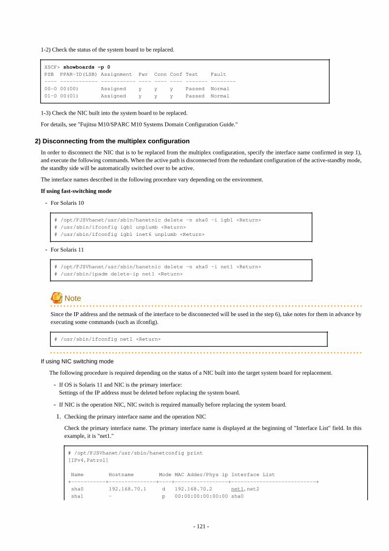
1-2) Check the status of the system board to be replaced.
XSCF> showboards -p 0PSB PPAR-ID(LSB) Assignment Pwr Conn Conf Test Fault---- ------------ ----------- ---- ---- ---- ------- --------00-0 00(00) Assigned y y y Passed Normal01-0 00(01) Assigned y y y Passed Normal
1-3) Check the NIC built into the system board to be replaced.
For details, see "Fujitsu M10/SPARC M10 Systems Domain Configuration Guide."
2) Disconnecting from the multiplex configuration
In order to disconnect the NIC that is to be replaced from the multiplex configuration, specify the interface name confirmed in step 1),and execute the following commands. When the active path is disconnected from the redundant configuration of the active-standby mode,the standby side will be automatically switched over to be active.
The interface names described in the following procedure vary depending on the environment.
If using fast-switching mode
- For Solaris 10
# /opt/FJSVhanet/usr/sbin/hanetnic delete -n sha0 -i igb1 <Return># /usr/sbin/ifconfig igb1 unplumb <Return># /usr/sbin/ifconfig igb1 inet6 unplumb <Return>
- For Solaris 11
# /opt/FJSVhanet/usr/sbin/hanetnic delete -n sha0 -i net1 <Return># /usr/sbin/ipadm delete-ip net1 <Return>
Note
Since the IP address and the netmask of the interface to be disconnected will be used in the step 6), take notes for them in advance byexecuting some commands (such as ifconfig).
# /usr/sbin/ifconfig net1 <Return>
If using NIC switching mode
The following procedure is required depending on the status of a NIC built into the target system board for replacement.
- If OS is Solaris 11 and NIC is the primary interface:Settings of the IP address must be deleted before replacing the system board.
- If NIC is the operation NIC, NIC switch is required manually before replacing the system board.
1. Checking the primary interface name and the operation NIC
Check the primary interface name. The primary interface name is displayed at the beginning of "Interface List" field. In thisexample, it is "net1."
# /opt/FJSVhanet/usr/sbin/hanetconfig print[IPv4,Patrol]
Name Hostname Mode MAC Adder/Phys ip Interface List+-----------+---------------+----+-----------------+---------------------------+ sha0 192.168.70.1 d 192.168.70.2 net1,net2 sha1 - p 00:00:00:00:00:00 sha0
- 121 -

[IPv6]
Name Hostname/prefix Mode Interface List+-----------+---------------------------------+----+---------------------------+
Check the operation NIC name, in this example, it is "net1."
# /opt/FJSVhanet/usr/sbin/dsphanet[IPv4,Patrol] Name Status Mode CL Device+----------+--------+----+----+------------------------------------------------+ sha0 Active d ON net1(ON),net2(OFF) sha1 Active p OFF sha0(ON) [IPv6] Name Status Mode CL Device+----------+--------+----+----+------------------------------------------------+
2. Stopping the HUB monitoring function and the patrol monitoring function
# /opt/FJSVhanet/usr/sbin/hanetpoll off <Return># /opt/FJSVhanet/usr/sbin/stpptl -n sha1 <Return>
3. Switching the physical interfaces
To execute this command, the NIC for replacement must be the operation NIC.
# /opt/FJSVhanet/usr/sbin/hanetnic change -n sha0 <Return>
4. Deleting IP address settings
To execute this command, OS must be Solaris 11 and NIC for replacement must be the primary interface.
# /usr/sbin/ifconfig net2 <Return># /usr/sbin/ipadm delete-ip net1 <Return>
Note
To return to the multiplex configuration, the IP address and the netmask of the interface specified by the ipadm delete-ip commandmust be set.Note the output result of the ifconfig command.
If using GS/SURE linkage mode # /opt/FJSVhanet/usr/sbin/hanetnic delete -n sha0 -i sha2 <Return>
3) Deleting the I/O device of the system board to be replaced from the logical domain
Delete the I/O device of the system board to be replaced from the logical domain before replacing the system board.
For details, see "Fujitsu M10/SPARC M10 Systems Domain Configuration Guide."
4) Replacing the system board
Replace the system board.
4-1) Delete the system board.
Delete the system board with the deleteboard(8) command.
- 122 -
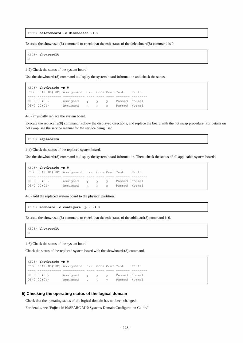
XSCF> deleteboard -c disconnect 01-0
Execute the showresult(8) command to check that the exit status of the deleteboard(8) command is 0.
XSCF> showresult0
4-2) Check the status of the system board.
Use the showboards(8) command to display the system board information and check the status.
XSCF> showboards -p 0PSB PPAR-ID(LSB) Assignment Pwr Conn Conf Test Fault---- ------------ ----------- ---- ---- ---- ------- --------00-0 00(00) Assigned y y y Passed Normal01-0 00(01) Assigned n n n Passed Normal
4-3) Physically replace the system board.
Execute the replacefru(8) command. Follow the displayed directions, and replace the board with the hot swap procedure. For details onhot swap, see the service manual for the service being used.
XSCF> replacefru
4-4) Check the status of the replaced system board.
Use the showboards(8) command to display the system board information. Then, check the status of all applicable system boards.
XSCF> showboards -p 0PSB PPAR-ID(LSB) Assignment Pwr Conn Conf Test Fault---- ------------ ----------- ---- ---- ---- ------- --------00-0 00(00) Assigned y y y Passed Normal01-0 00(01) Assigned n n n Passed Normal
4-5) Add the replaced system board to the physical partition.
XSCF> addboard -c configure -p 0 01-0
Execute the showresult(8) command to check that the exit status of the addboard(8) command is 0.
XSCF> showresult0
4-6) Check the status of the system board.
Check the status of the replaced system board with the showboards(8) command.
XSCF> showboards -p 0PSB PPAR-ID(LSB) Assignment Pwr Conn Conf Test Fault---- ------------ ----------- ---- ---- ---- ------- --------00-0 00(00) Assigned y y y Passed Normal01-0 00(01) Assigned y y y Passed Normal
5) Checking the operating status of the logical domain
Check that the operating status of the logical domain has not been changed.
For details, see "Fujitsu M10/SPARC M10 Systems Domain Configuration Guide."
- 123 -
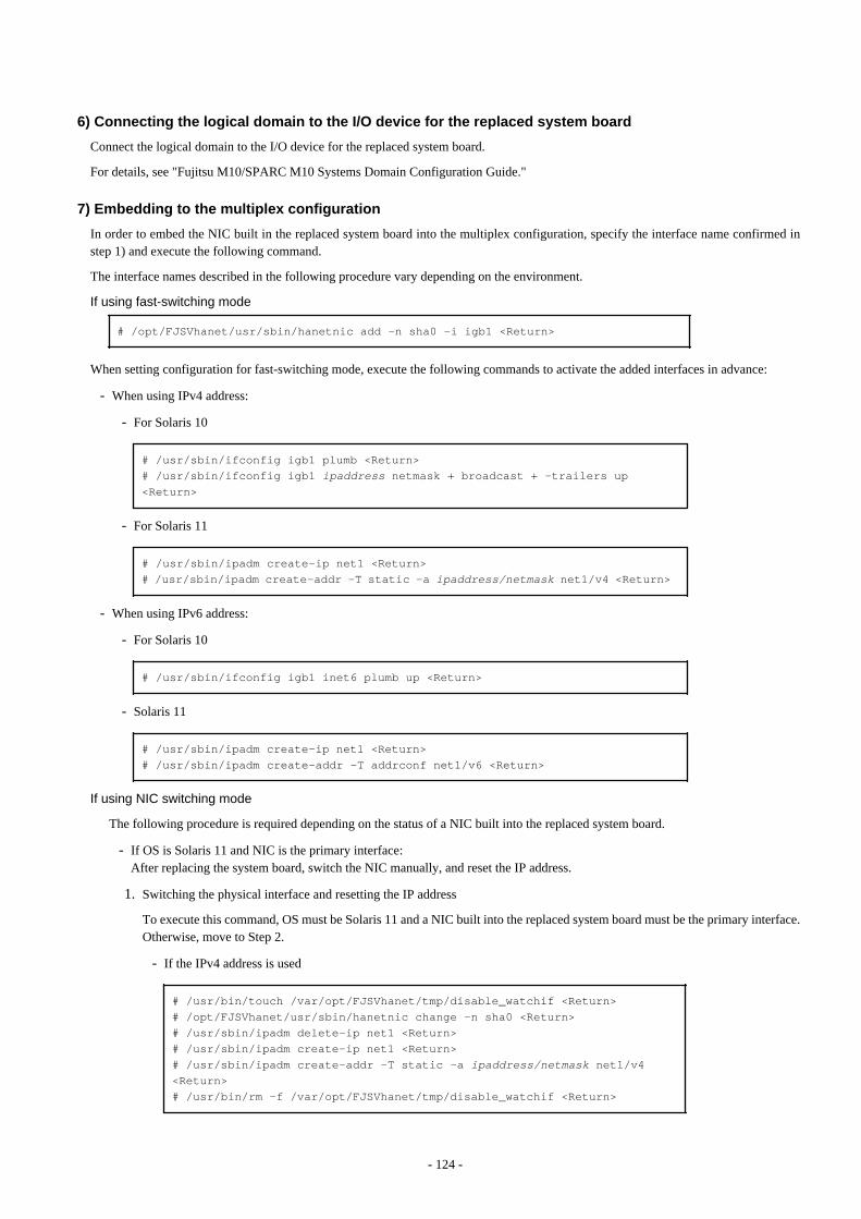
6) Connecting the logical domain to the I/O device for the replaced system board
Connect the logical domain to the I/O device for the replaced system board.
For details, see "Fujitsu M10/SPARC M10 Systems Domain Configuration Guide."
7) Embedding to the multiplex configuration
In order to embed the NIC built in the replaced system board into the multiplex configuration, specify the interface name confirmed instep 1) and execute the following command.
The interface names described in the following procedure vary depending on the environment.
If using fast-switching mode # /opt/FJSVhanet/usr/sbin/hanetnic add -n sha0 -i igb1 <Return>
When setting configuration for fast-switching mode, execute the following commands to activate the added interfaces in advance:
- When using IPv4 address:
- For Solaris 10
# /usr/sbin/ifconfig igb1 plumb <Return># /usr/sbin/ifconfig igb1 ipaddress netmask + broadcast + -trailers up <Return>
- For Solaris 11
# /usr/sbin/ipadm create-ip net1 <Return># /usr/sbin/ipadm create-addr -T static -a ipaddress/netmask net1/v4 <Return>
- When using IPv6 address:
- For Solaris 10
# /usr/sbin/ifconfig igb1 inet6 plumb up <Return>
- Solaris 11
# /usr/sbin/ipadm create-ip net1 <Return># /usr/sbin/ipadm create-addr -T addrconf net1/v6 <Return>
If using NIC switching mode
The following procedure is required depending on the status of a NIC built into the replaced system board.
- If OS is Solaris 11 and NIC is the primary interface:After replacing the system board, switch the NIC manually, and reset the IP address.
1. Switching the physical interface and resetting the IP address
To execute this command, OS must be Solaris 11 and a NIC built into the replaced system board must be the primary interface.Otherwise, move to Step 2.
- If the IPv4 address is used
# /usr/bin/touch /var/opt/FJSVhanet/tmp/disable_watchif <Return># /opt/FJSVhanet/usr/sbin/hanetnic change -n sha0 <Return># /usr/sbin/ipadm delete-ip net1 <Return># /usr/sbin/ipadm create-ip net1 <Return># /usr/sbin/ipadm create-addr -T static -a ipaddress/netmask net1/v4 <Return># /usr/bin/rm -f /var/opt/FJSVhanet/tmp/disable_watchif <Return>
- 124 -

- If the IPv6 address is used
# /usr/bin/touch /var/opt/FJSVhanet/tmp/disable_watchif <Return># /opt/FJSVhanet/usr/sbin/hanetnic change -n sha0 <Return># /usr/sbin/ipadm delete-ip net1 <Return># /usr/sbin/ipadm create-ip net1 <Return># /usr/sbin/ipadm create-addr -T addrconf net1/v6 <Return># /usr/bin/rm -f /var/opt/FJSVhanet/tmp/disable_watchif <Return>
2. Starting the HUB monitoring function and the patrol monitoring function
# /opt/FJSVhanet/usr/sbin/strptl -n sha1 <Return># /opt/FJSVhanet/usr/sbin/hanetpoll on <Return>
3. Switching the physical interfaces
Switch the physical interfaces as necessary.
# /opt/FJSVhanet/usr/sbin/hanetnic add -n sha0 -i sha2 <Return>
If using GS/SURE linkage mode # /opt/FJSVhanet/usr/sbin/hanetnic add -n sha0 -i sha2 <Return>
8) Reverting the active path (only if necessary)
If changing the active path through the hot swap, perform a reversion of the active path as necessary.
4.5.2.2 Replacing the system board using the DR of XSCF (SPARC Enterprise M4000/M5000/M8000/M9000)
1) Checking the system configuration
Check the NIC built into the system board to be replaced according to the following procedure.
1-1) Check the domain status.
Using the showdcl(8) command, display the domain information and confirm the domain status.
XSCF> showdcl -d 0 DID LSB XSB Status 00 Running 00 00-0 01 01-0
1-2) Check the status of the system board to be replaced.
Using the showboards(8) command, display the system board information and confirm the status of the system board to be deleted.
XSCF> showboards 01-0 <Return>XSB DID(LSB) Assignment Pwr Conn Conf Test Fault---- -------- ----------- ---- ---- ---- ------- --------01-0 00(01) Assigned y y y Passed Normal
1-3) Check the NIC built into the system board to be replaced.
Using the showdevices(8) command, check the NIC interface name built into the system board to be replaced.
XSCF> showdevices 01-0CPU:
- 125 -
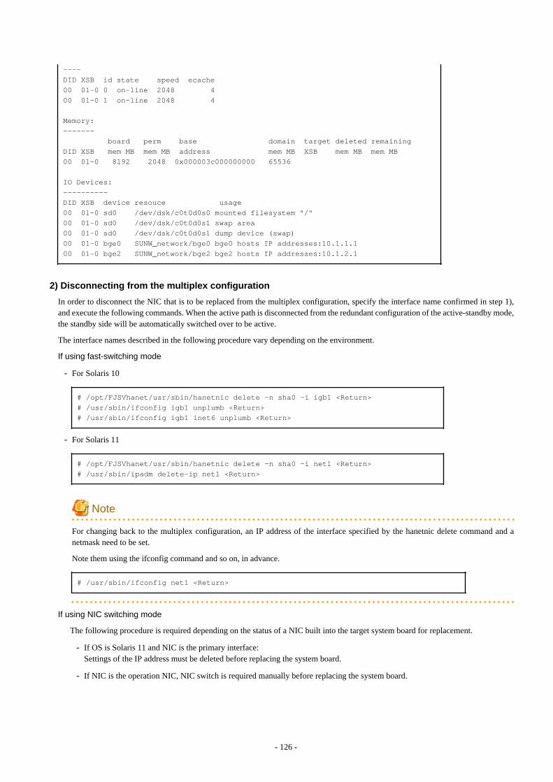
----DID XSB id state speed ecache00 01-0 0 on-line 2048 400 01-0 1 on-line 2048 4
Memory:------- board perm base domain target deleted remainingDID XSB mem MB mem MB address mem MB XSB mem MB mem MB00 01-0 8192 2048 0x000003c000000000 65536
IO Devices:----------DID XSB device resouce usage00 01-0 sd0 /dev/dsk/c0t0d0s0 mounted filesystem "/"00 01-0 sd0 /dev/dsk/c0t0d0s1 swap area00 01-0 sd0 /dev/dsk/c0t0d0s1 dump device (swap)00 01-0 bge0 SUNW_network/bge0 bge0 hosts IP addresses:10.1.1.100 01-0 bge2 SUNW_network/bge2 bge2 hosts IP addresses:10.1.2.1
2) Disconnecting from the multiplex configuration
In order to disconnect the NIC that is to be replaced from the multiplex configuration, specify the interface name confirmed in step 1),and execute the following commands. When the active path is disconnected from the redundant configuration of the active-standby mode,the standby side will be automatically switched over to be active.
The interface names described in the following procedure vary depending on the environment.
If using fast-switching mode
- For Solaris 10
# /opt/FJSVhanet/usr/sbin/hanetnic delete -n sha0 -i igb1 <Return># /usr/sbin/ifconfig igb1 unplumb <Return># /usr/sbin/ifconfig igb1 inet6 unplumb <Return>
- For Solaris 11
# /opt/FJSVhanet/usr/sbin/hanetnic delete -n sha0 -i net1 <Return># /usr/sbin/ipadm delete-ip net1 <Return>
Note
For changing back to the multiplex configuration, an IP address of the interface specified by the hanetnic delete command and anetmask need to be set.
Note them using the ifconfig command and so on, in advance.
# /usr/sbin/ifconfig net1 <Return>
If using NIC switching mode
The following procedure is required depending on the status of a NIC built into the target system board for replacement.
- If OS is Solaris 11 and NIC is the primary interface:Settings of the IP address must be deleted before replacing the system board.
- If NIC is the operation NIC, NIC switch is required manually before replacing the system board.
- 126 -
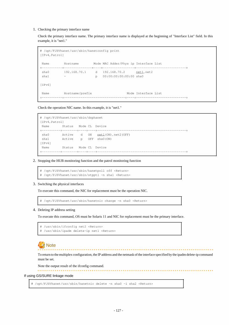
1. Checking the primary interface name
Check the primary interface name. The primary interface name is displayed at the beginning of "Interface List" field. In thisexample, it is "net1."
# /opt/FJSVhanet/usr/sbin/hanetconfig print[IPv4,Patrol]
Name Hostname Mode MAC Adder/Phys ip Interface List+-----------+---------------+----+-----------------+---------------------------+ sha0 192.168.70.1 d 192.168.70.2 net1,net2 sha1 - p 00:00:00:00:00:00 sha0
[IPv6]
Name Hostname/prefix Mode Interface List+-----------+---------------------------------+----+---------------------------+
Check the operation NIC name. In this example, it is "net1."
# /opt/FJSVhanet/usr/sbin/dsphanet[IPv4,Patrol] Name Status Mode CL Device+----------+--------+----+----+------------------------------------------------+ sha0 Active d ON net1(ON),net2(OFF) sha1 Active p OFF sha0(ON) [IPv6] Name Status Mode CL Device+----------+--------+----+----+------------------------------------------------+
2. Stopping the HUB monitoring function and the patrol monitoring function
# /opt/FJSVhanet/usr/sbin/hanetpoll off <Return># /opt/FJSVhanet/usr/sbin/stpptl -n sha1 <Return>
3. Switching the physical interfaces
To execute this command, the NIC for replacement must be the operation NIC.
# /opt/FJSVhanet/usr/sbin/hanetnic change -n sha0 <Return>
4. Deleting IP address setting
To execute this command, OS must be Solaris 11 and NIC for replacement must be the primary interface.
# /usr/sbin/ifconfig net2 <Return># /usr/sbin/ipadm delete-ip net1 <Return>
Note
To return to the multiplex configuration, the IP address and the netmask of the interface specified by the ipadm delete-ip commandmust be set.
Note the output result of the ifconfig command.
If using GS/SURE linkage mode # /opt/FJSVhanet/usr/sbin/hanetnic delete -n sha0 -i sha2 <Return>
- 127 -
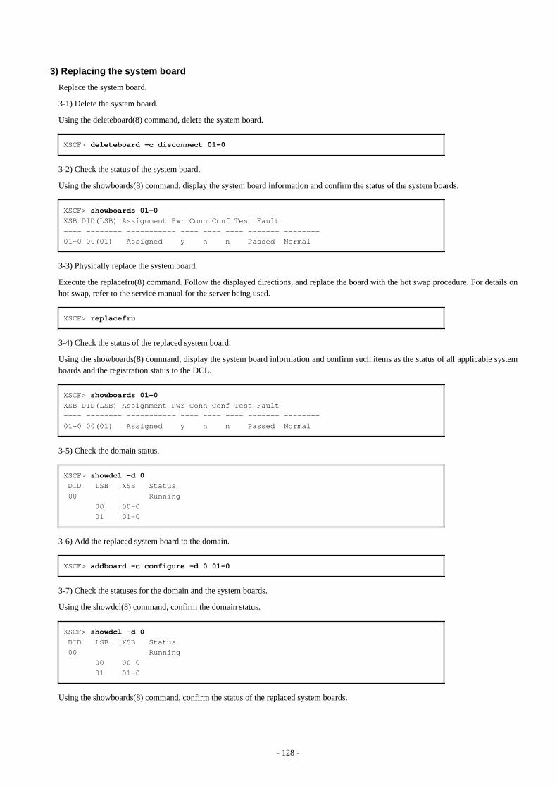
3) Replacing the system board
Replace the system board.
3-1) Delete the system board.
Using the deleteboard(8) command, delete the system board.
XSCF> deleteboard -c disconnect 01-0
3-2) Check the status of the system board.
Using the showboards(8) command, display the system board information and confirm the status of the system boards.
XSCF> showboards 01-0XSB DID(LSB) Assignment Pwr Conn Conf Test Fault---- -------- ----------- ---- ---- ---- ------- --------01-0 00(01) Assigned y n n Passed Normal
3-3) Physically replace the system board.
Execute the replacefru(8) command. Follow the displayed directions, and replace the board with the hot swap procedure. For details onhot swap, refer to the service manual for the server being used.
XSCF> replacefru
3-4) Check the status of the replaced system board.
Using the showboards(8) command, display the system board information and confirm such items as the status of all applicable systemboards and the registration status to the DCL.
XSCF> showboards 01-0XSB DID(LSB) Assignment Pwr Conn Conf Test Fault---- -------- ----------- ---- ---- ---- ------- --------01-0 00(01) Assigned y n n Passed Normal
3-5) Check the domain status.
XSCF> showdcl -d 0 DID LSB XSB Status 00 Running 00 00-0 01 01-0
3-6) Add the replaced system board to the domain.
XSCF> addboard -c configure -d 0 01-0
3-7) Check the statuses for the domain and the system boards.
Using the showdcl(8) command, confirm the domain status.
XSCF> showdcl -d 0 DID LSB XSB Status 00 Running 00 00-0 01 01-0
Using the showboards(8) command, confirm the status of the replaced system boards.
- 128 -
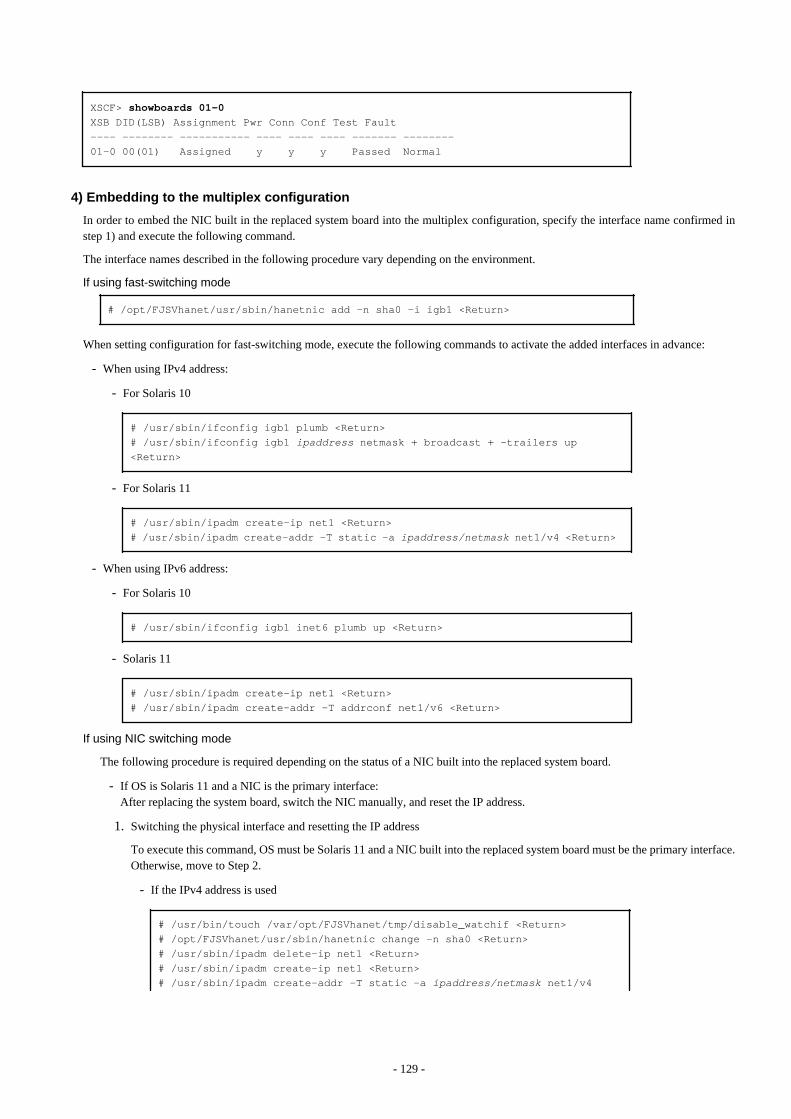
XSCF> showboards 01-0XSB DID(LSB) Assignment Pwr Conn Conf Test Fault---- -------- ----------- ---- ---- ---- ------- --------01-0 00(01) Assigned y y y Passed Normal
4) Embedding to the multiplex configuration
In order to embed the NIC built in the replaced system board into the multiplex configuration, specify the interface name confirmed instep 1) and execute the following command.
The interface names described in the following procedure vary depending on the environment.
If using fast-switching mode # /opt/FJSVhanet/usr/sbin/hanetnic add -n sha0 -i igb1 <Return>
When setting configuration for fast-switching mode, execute the following commands to activate the added interfaces in advance:
- When using IPv4 address:
- For Solaris 10
# /usr/sbin/ifconfig igb1 plumb <Return># /usr/sbin/ifconfig igb1 ipaddress netmask + broadcast + -trailers up <Return>
- For Solaris 11
# /usr/sbin/ipadm create-ip net1 <Return># /usr/sbin/ipadm create-addr -T static -a ipaddress/netmask net1/v4 <Return>
- When using IPv6 address:
- For Solaris 10
# /usr/sbin/ifconfig igb1 inet6 plumb up <Return>
- Solaris 11
# /usr/sbin/ipadm create-ip net1 <Return># /usr/sbin/ipadm create-addr -T addrconf net1/v6 <Return>
If using NIC switching mode
The following procedure is required depending on the status of a NIC built into the replaced system board.
- If OS is Solaris 11 and a NIC is the primary interface:After replacing the system board, switch the NIC manually, and reset the IP address.
1. Switching the physical interface and resetting the IP address
To execute this command, OS must be Solaris 11 and a NIC built into the replaced system board must be the primary interface.Otherwise, move to Step 2.
- If the IPv4 address is used
# /usr/bin/touch /var/opt/FJSVhanet/tmp/disable_watchif <Return># /opt/FJSVhanet/usr/sbin/hanetnic change -n sha0 <Return># /usr/sbin/ipadm delete-ip net1 <Return># /usr/sbin/ipadm create-ip net1 <Return># /usr/sbin/ipadm create-addr -T static -a ipaddress/netmask net1/v4
- 129 -
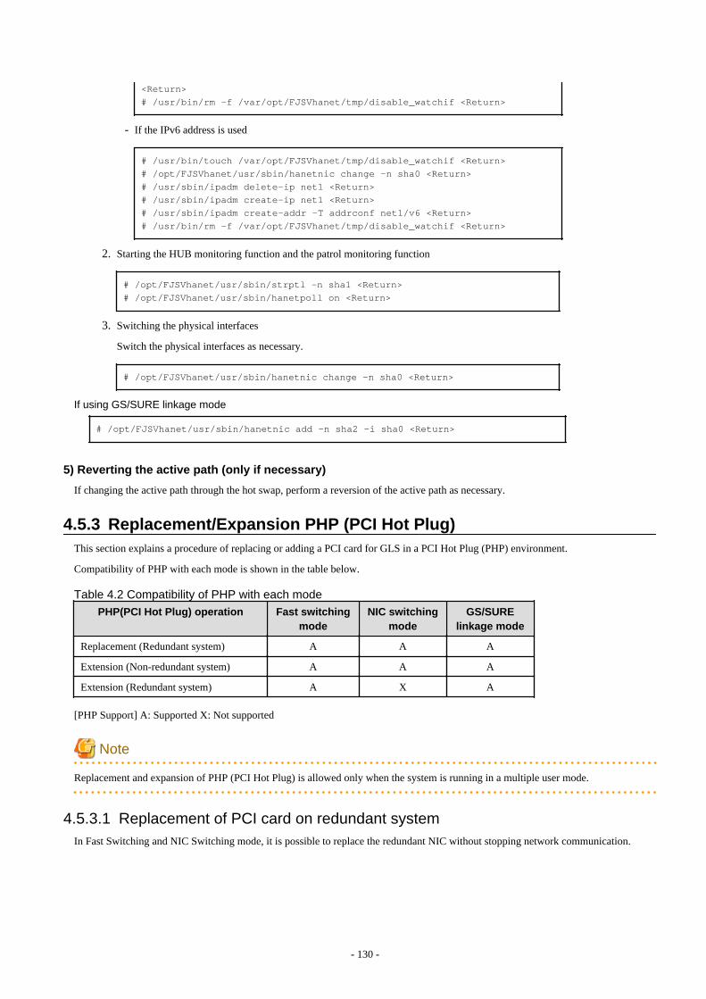
<Return># /usr/bin/rm -f /var/opt/FJSVhanet/tmp/disable_watchif <Return>
- If the IPv6 address is used
# /usr/bin/touch /var/opt/FJSVhanet/tmp/disable_watchif <Return># /opt/FJSVhanet/usr/sbin/hanetnic change -n sha0 <Return># /usr/sbin/ipadm delete-ip net1 <Return># /usr/sbin/ipadm create-ip net1 <Return># /usr/sbin/ipadm create-addr -T addrconf net1/v6 <Return># /usr/bin/rm -f /var/opt/FJSVhanet/tmp/disable_watchif <Return>
2. Starting the HUB monitoring function and the patrol monitoring function
# /opt/FJSVhanet/usr/sbin/strptl -n sha1 <Return># /opt/FJSVhanet/usr/sbin/hanetpoll on <Return>
3. Switching the physical interfaces
Switch the physical interfaces as necessary.
# /opt/FJSVhanet/usr/sbin/hanetnic change -n sha0 <Return>
If using GS/SURE linkage mode # /opt/FJSVhanet/usr/sbin/hanetnic add -n sha2 -i sha0 <Return>
5) Reverting the active path (only if necessary)
If changing the active path through the hot swap, perform a reversion of the active path as necessary.
4.5.3 Replacement/Expansion PHP (PCI Hot Plug)This section explains a procedure of replacing or adding a PCI card for GLS in a PCI Hot Plug (PHP) environment.
Compatibility of PHP with each mode is shown in the table below.
Table 4.2 Compatibility of PHP with each mode
PHP(PCI Hot Plug) operation Fast switchingmode
NIC switchingmode
GS/SURElinkage mode
Replacement (Redundant system) A A A
Extension (Non-redundant system) A A A
Extension (Redundant system) A X A
[PHP Support] A: Supported X: Not supported
Note
Replacement and expansion of PHP (PCI Hot Plug) is allowed only when the system is running in a multiple user mode.
4.5.3.1 Replacement of PCI card on redundant systemIn Fast Switching and NIC Switching mode, it is possible to replace the redundant NIC without stopping network communication.
- 130 -
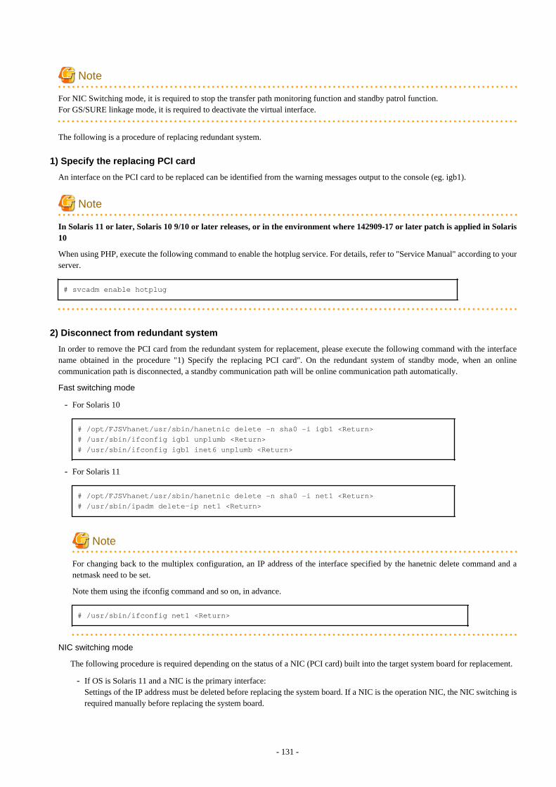
Note
For NIC Switching mode, it is required to stop the transfer path monitoring function and standby patrol function.For GS/SURE linkage mode, it is required to deactivate the virtual interface.
The following is a procedure of replacing redundant system.
1) Specify the replacing PCI card
An interface on the PCI card to be replaced can be identified from the warning messages output to the console (eg. igb1).
Note
In Solaris 11 or later, Solaris 10 9/10 or later releases, or in the environment where 142909-17 or later patch is applied in Solaris10
When using PHP, execute the following command to enable the hotplug service. For details, refer to "Service Manual" according to yourserver.
# svcadm enable hotplug
2) Disconnect from redundant system
In order to remove the PCI card from the redundant system for replacement, please execute the following command with the interfacename obtained in the procedure "1) Specify the replacing PCI card". On the redundant system of standby mode, when an onlinecommunication path is disconnected, a standby communication path will be online communication path automatically.
Fast switching mode
- For Solaris 10
# /opt/FJSVhanet/usr/sbin/hanetnic delete -n sha0 -i igb1 <Return># /usr/sbin/ifconfig igb1 unplumb <Return># /usr/sbin/ifconfig igb1 inet6 unplumb <Return>
- For Solaris 11
# /opt/FJSVhanet/usr/sbin/hanetnic delete -n sha0 -i net1 <Return># /usr/sbin/ipadm delete-ip net1 <Return>
Note
For changing back to the multiplex configuration, an IP address of the interface specified by the hanetnic delete command and anetmask need to be set.
Note them using the ifconfig command and so on, in advance.
# /usr/sbin/ifconfig net1 <Return>
NIC switching mode
The following procedure is required depending on the status of a NIC (PCI card) built into the target system board for replacement.
- If OS is Solaris 11 and a NIC is the primary interface: Settings of the IP address must be deleted before replacing the system board. If a NIC is the operation NIC, the NIC switching isrequired manually before replacing the system board.
- 131 -
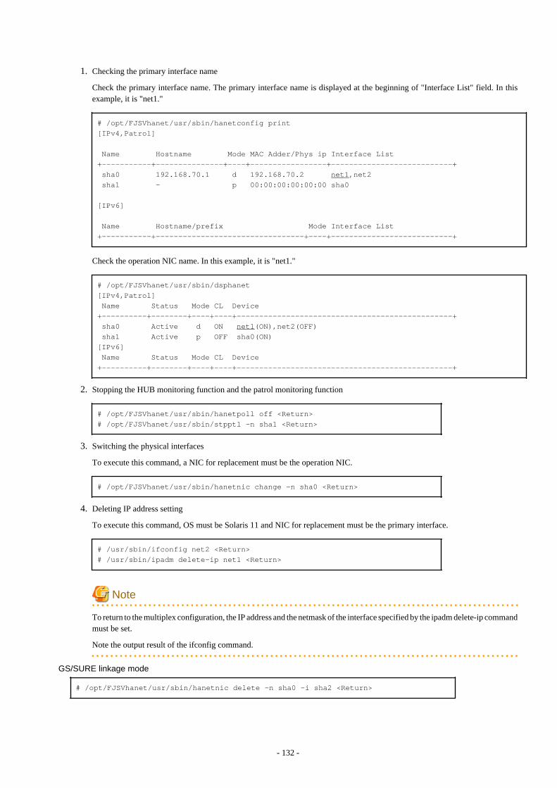
1. Checking the primary interface name
Check the primary interface name. The primary interface name is displayed at the beginning of "Interface List" field. In thisexample, it is "net1."
# /opt/FJSVhanet/usr/sbin/hanetconfig print[IPv4,Patrol]
Name Hostname Mode MAC Adder/Phys ip Interface List+-----------+---------------+----+-----------------+---------------------------+ sha0 192.168.70.1 d 192.168.70.2 net1,net2 sha1 - p 00:00:00:00:00:00 sha0
[IPv6]
Name Hostname/prefix Mode Interface List+-----------+---------------------------------+----+---------------------------+
Check the operation NIC name. In this example, it is "net1."
# /opt/FJSVhanet/usr/sbin/dsphanet[IPv4,Patrol] Name Status Mode CL Device+----------+--------+----+----+------------------------------------------------+ sha0 Active d ON net1(ON),net2(OFF) sha1 Active p OFF sha0(ON) [IPv6] Name Status Mode CL Device+----------+--------+----+----+------------------------------------------------+
2. Stopping the HUB monitoring function and the patrol monitoring function
# /opt/FJSVhanet/usr/sbin/hanetpoll off <Return># /opt/FJSVhanet/usr/sbin/stpptl -n sha1 <Return>
3. Switching the physical interfaces
To execute this command, a NIC for replacement must be the operation NIC.
# /opt/FJSVhanet/usr/sbin/hanetnic change -n sha0 <Return>
4. Deleting IP address setting
To execute this command, OS must be Solaris 11 and NIC for replacement must be the primary interface.
# /usr/sbin/ifconfig net2 <Return># /usr/sbin/ipadm delete-ip net1 <Return>
Note
To return to the multiplex configuration, the IP address and the netmask of the interface specified by the ipadm delete-ip commandmust be set.
Note the output result of the ifconfig command.
GS/SURE linkage mode # /opt/FJSVhanet/usr/sbin/hanetnic delete -n sha0 -i sha2 <Return>
- 132 -
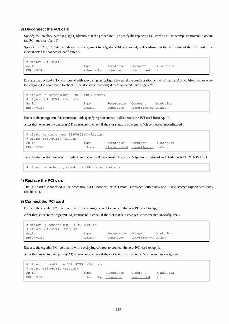
3) Disconnect the PCI card
Specify the interface name (eg, igb1) identified in the procedure "1) Specify the replacing PCI card." to "inst2comp" command to obtainthe PCI bus slot "Ap_Id".
Specify the "Ap_Id" obtained above as an argument to "cfgadm"(1M) command, and confirm that the slot status of the PCI card to bedisconnected is "connected configured".
# cfgadm BB#0-PCI#0Ap_Id Type Receptacle Occupant ConditionBB#0-PCI#0 etherne/hp connected configured ok
Execute the uncfgadm(1M) command with specifying unconfigure to cancel the configuration of the PCI card at Ap_Id. After that, executethe cfgadm(1M) command to check if the slot status is changed to "connected unconfigured".
# cfgadm -c unconfigure BB#0-PCI#0 <Return># cfgadm BB#0-PCI#0 <Return>Ap_Id Type Receptacle Occupant ConditionBB#0-PCI#0 unknown connected unconfigured unknown
Execute the uncfgadm(1M) command with specifying disconnect to disconnect the PCI card from Ap_Id.
After that, execute the cfgadm(1M) command to check if the slot status is changed to "disconnected unconfigured".
# cfgadm -c disconnect BB#0-PCI#0 <Return># cfgadm BB#0-PCI#0 <Return>Ap_Id Type Receptacle Occupant ConditionBB#0-PCI#0 unknown disconnected unconfigured unknown
To indicate the slot position for replacement, specify the obtained "Ap_Id" to "cfgadm" command and blink the ATTENTION LED.
# cfgadm -x led=attn,mode=blink BB#0-PCI#0 <Return>
4) Replace the PCI card
The PCI card disconnected in the procedure "3) Disconnect the PCI card" is replaced with a new one. Our customer support staff doesthis for you.
5) Connect the PCI card
Execute the cfgadm(1M) command with specifying connect to connect the new PCI card to Ap_Id.
After that, execute the cfgadm(1M) command to check if the slot status is changed to "connected unconfigured".
# cfgadm -c connect BB#0-PCI#0 <Return># cfgadm BB#0-PCI#0 <Return>Ap_Id Type Receptacle Occupant ConditionBB#0-PCI#0 unknown connected unconfigured unknown
Execute the cfgadm(1M) command with specifying connect to connect the new PCI card to Ap_Id.
After that, execute the cfgadm(1M) command to check if the slot status is changed to "connected unconfigured".
# cfgadm -c configure BB#0-PCI#0 <Return># cfgadm BB#0-PCI#0 <Return>Ap_Id Type Receptacle Occupant ConditionBB#0-PCI#0 etherne/hp connected configured ok
- 133 -
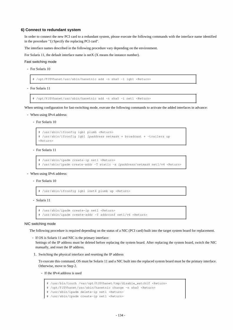
6) Connect to redundant system
In order to connect the new PCI card to a redundant system, please execute the following commands with the interface name identifiedin the procedure "1) Specify the replacing PCI card".
The interface names described in the following procedure vary depending on the environment.
For Solaris 11, the default interface name is netX (X means the instance number).
Fast switching mode
- For Solaris 10
# /opt/FJSVhanet/usr/sbin/hanetnic add -n sha0 -i igb1 <Return>
- For Solaris 11
# /opt/FJSVhanet/usr/sbin/hanetnic add -n sha0 -i net1 <Return>
When setting configuration for fast-switching mode, execute the following commands to activate the added interfaces in advance:
- When using IPv4 address:
- For Solaris 10
# /usr/sbin/ifconfig igb1 plumb <Return># /usr/sbin/ifconfig igb1 ipaddress netmask + broadcast + -trailers up <Return>
- For Solaris 11
# /usr/sbin/ipadm create-ip net1 <Return># /usr/sbin/ipadm create-addr -T static -a ipaddress/netmask net1/v4 <Return>
- When using IPv6 address:
- For Solaris 10
# /usr/sbin/ifconfig igb1 inet6 plumb up <Return>
- Solaris 11
# /usr/sbin/ipadm create-ip net1 <Return># /usr/sbin/ipadm create-addr -T addrconf net1/v6 <Return>
NIC switching mode
The following procedure is required depending on the status of a NIC (PCI card) built into the target system board for replacement.
- If OS is Solaris 11 and NIC is the primary interface:Settings of the IP address must be deleted before replacing the system board. After replacing the system board, switch the NICmanually, and reset the IP address.
1. Switching the physical interface and resetting the IP address
To execute this command, OS must be Solaris 11 and a NIC built into the replaced system board must be the primary interface.Otherwise, move to Step 2.
- If the IPv4 address is used
# /usr/bin/touch /var/opt/FJSVhanet/tmp/disable_watchif <Return># /opt/FJSVhanet/usr/sbin/hanetnic change -n sha0 <Return># /usr/sbin/ipadm delete-ip net1 <Return># /usr/sbin/ipadm create-ip net1 <Return>
- 134 -
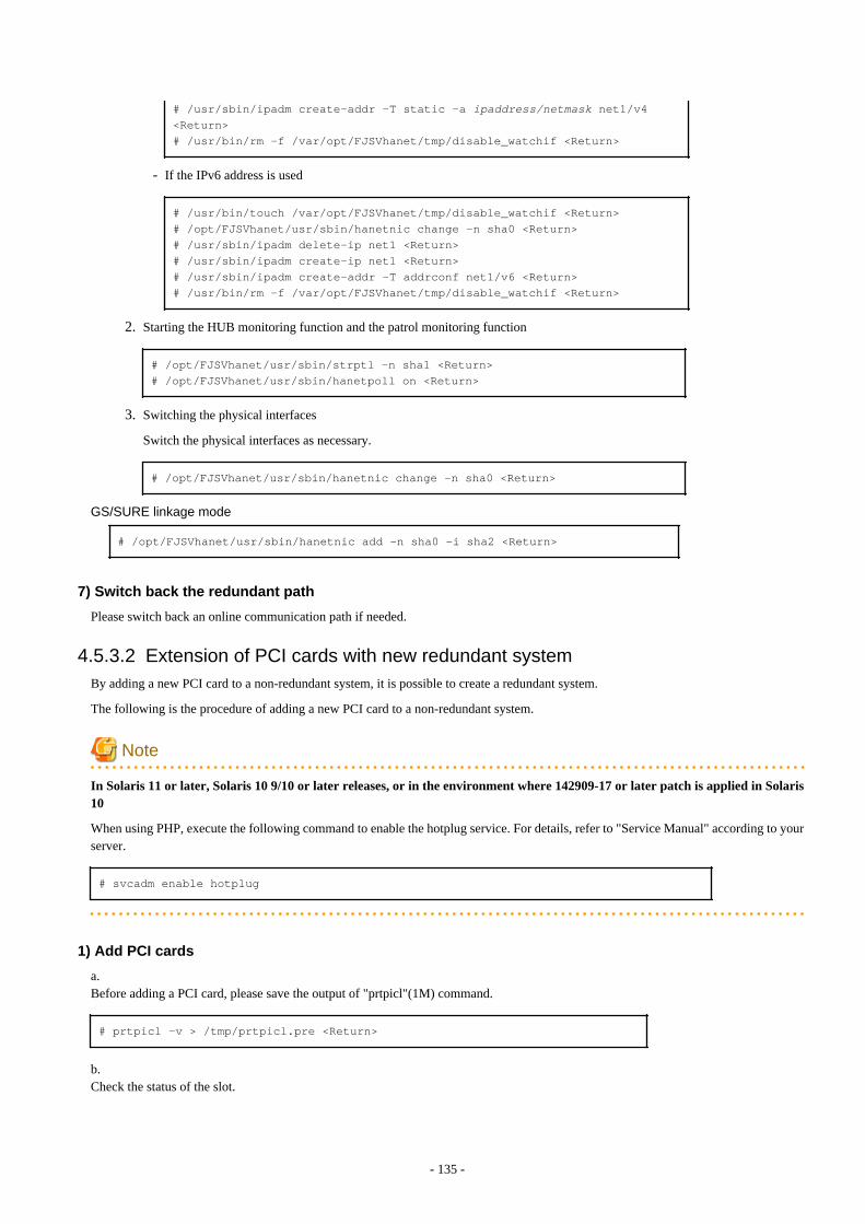
# /usr/sbin/ipadm create-addr -T static -a ipaddress/netmask net1/v4 <Return># /usr/bin/rm -f /var/opt/FJSVhanet/tmp/disable_watchif <Return>
- If the IPv6 address is used
# /usr/bin/touch /var/opt/FJSVhanet/tmp/disable_watchif <Return># /opt/FJSVhanet/usr/sbin/hanetnic change -n sha0 <Return># /usr/sbin/ipadm delete-ip net1 <Return># /usr/sbin/ipadm create-ip net1 <Return># /usr/sbin/ipadm create-addr -T addrconf net1/v6 <Return># /usr/bin/rm -f /var/opt/FJSVhanet/tmp/disable_watchif <Return>
2. Starting the HUB monitoring function and the patrol monitoring function
# /opt/FJSVhanet/usr/sbin/strptl -n sha1 <Return># /opt/FJSVhanet/usr/sbin/hanetpoll on <Return>
3. Switching the physical interfaces
Switch the physical interfaces as necessary.
# /opt/FJSVhanet/usr/sbin/hanetnic change -n sha0 <Return>
GS/SURE linkage mode # /opt/FJSVhanet/usr/sbin/hanetnic add -n sha0 -i sha2 <Return>
7) Switch back the redundant path
Please switch back an online communication path if needed.
4.5.3.2 Extension of PCI cards with new redundant systemBy adding a new PCI card to a non-redundant system, it is possible to create a redundant system.
The following is the procedure of adding a new PCI card to a non-redundant system.
Note
In Solaris 11 or later, Solaris 10 9/10 or later releases, or in the environment where 142909-17 or later patch is applied in Solaris10
When using PHP, execute the following command to enable the hotplug service. For details, refer to "Service Manual" according to yourserver.
# svcadm enable hotplug
1) Add PCI cards
a.Before adding a PCI card, please save the output of "prtpicl"(1M) command.
# prtpicl -v > /tmp/prtpicl.pre <Return>
b.Check the status of the slot.
- 135 -

An example of adding a PCI card to BB#1-PCI#0 is shown in this section.
Please confirm that the status of the PCI slot where a PCI card is added is "empty unconfigured" by using "cfgadm" (1M) command.
# cfgadm BB#1-PCI#0 <Return>Ap_Id Type Receptacle Occupant ConditionBB#1-PCI#0 unknown empty unconfigured unknown
c.To indicate the slot position for expansion, specify the "Ap_Id" identified in the procedure 1)b to "cfgadm" command and blink theATTENTION LED.
# cfgadm -x led=attn,mode=blink BB#1-PCI#0 <Return>
d.Add a PCI card after the POWER LED of the target PCI bus slot has turned off.This operation is performed by our customer support.
e.Please confirm that the PCI slot status which extended PCI cards is "disconnected unconfigured" by using cfgadm (1M) command.
# cfgadm BB#1-PCI#0 <Return>Ap_Id Type Receptacle Occupant ConditionBB#1-PCI#0 unknown disconnected unconfigured unknown
2) Connect PCI cards
Execute the cfgadm(1M) command with specifying connect to connect the new PCI card to Ap_Id.After that, execute the cfgadm(1M) command to check if the slot status is changed to "connected unconfigured".
# cfgadm -c connect BB#1-PCI#0 <Return># cfgadm BB#1-PCI#0 <Return>Ap_Id Type Receptacle Occupant ConditionBB#1-PCI#0 unknown connected unconfigured unknown
Execute the cfgadm(1M) command with specifying connect to connect the added PCI card to Ap_Id.After that, execute the cfgadm(1M) command to check if the slot status is changed to "connected unconfigured".
# cfgadm -c configure BB#1-PCI#0 <Return># cfgadm BB#1-PCI#0 <Return>Ap_Id Type Receptacle Occupant ConditionBB#1-PCI#0 etherne/hp connected configured ok
3) Connect equipment to PCI cards
The extended PCI card is connected with network equipment by the cable.
4) Setup driver
The driver configuration is added by following operations.
a.The interface name is investigated in order to configure drivers and high layer products.Please save the result of the prtcicl (1M) command, and obtain the difference information between current result and the result taken at"1) a." Then, the driver instance number for the extended PCI card is obtained.In the following example, since the instance number is 1, it can be determined that the interface name of the extended PCI card is "igb1."
# prtpicl -v > /tmp/prtpicl.post <Return># diff /tmp/prtpicl.pre /tmp/prtpicl.post | more <Return>
- 136 -
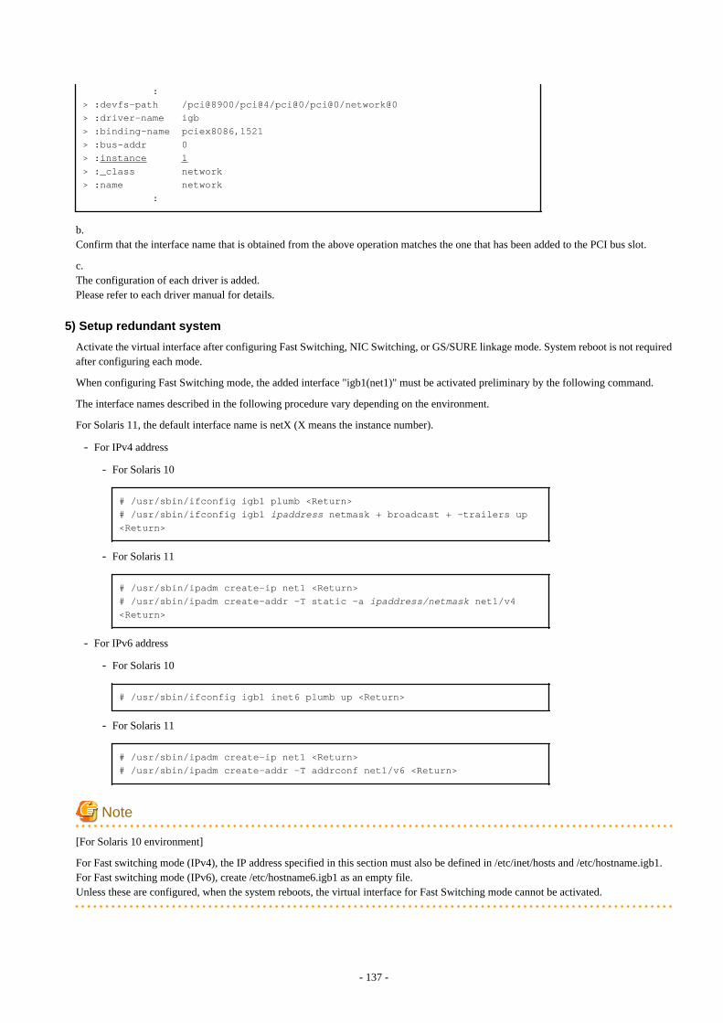
:> :devfs-path /pci@8900/pci@4/pci@0/pci@0/network@0> :driver-name igb> :binding-name pciex8086,1521> :bus-addr 0> :instance 1> :_class network> :name network :
b.Confirm that the interface name that is obtained from the above operation matches the one that has been added to the PCI bus slot.
c.The configuration of each driver is added. Please refer to each driver manual for details.
5) Setup redundant system
Activate the virtual interface after configuring Fast Switching, NIC Switching, or GS/SURE linkage mode. System reboot is not requiredafter configuring each mode.
When configuring Fast Switching mode, the added interface "igb1(net1)" must be activated preliminary by the following command.
The interface names described in the following procedure vary depending on the environment.
For Solaris 11, the default interface name is netX (X means the instance number).
- For IPv4 address
- For Solaris 10
# /usr/sbin/ifconfig igb1 plumb <Return># /usr/sbin/ifconfig igb1 ipaddress netmask + broadcast + -trailers up <Return>
- For Solaris 11
# /usr/sbin/ipadm create-ip net1 <Return># /usr/sbin/ipadm create-addr -T static -a ipaddress/netmask net1/v4 <Return>
- For IPv6 address
- For Solaris 10
# /usr/sbin/ifconfig igb1 inet6 plumb up <Return>
- For Solaris 11
# /usr/sbin/ipadm create-ip net1 <Return># /usr/sbin/ipadm create-addr -T addrconf net1/v6 <Return>
Note
[For Solaris 10 environment]
For Fast switching mode (IPv4), the IP address specified in this section must also be defined in /etc/inet/hosts and /etc/hostname.igb1.For Fast switching mode (IPv6), create /etc/hostname6.igb1 as an empty file.Unless these are configured, when the system reboots, the virtual interface for Fast Switching mode cannot be activated.
- 137 -
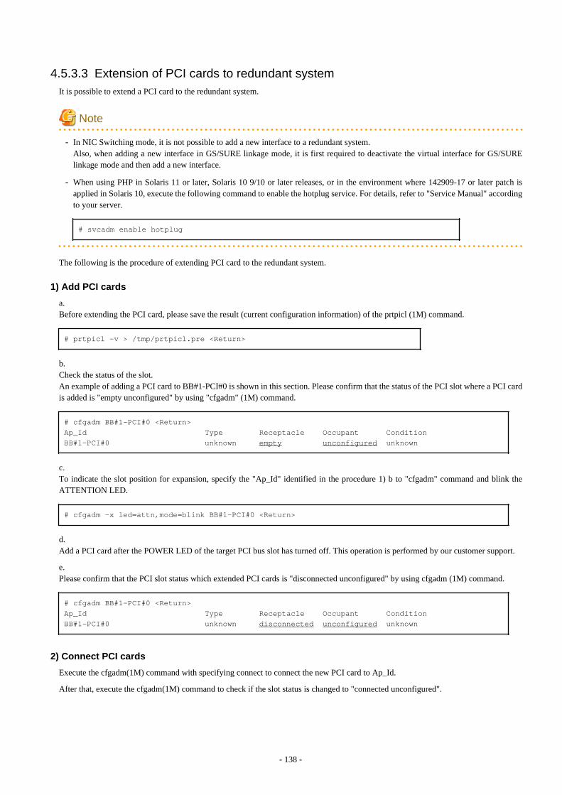
4.5.3.3 Extension of PCI cards to redundant systemIt is possible to extend a PCI card to the redundant system.
Note
- In NIC Switching mode, it is not possible to add a new interface to a redundant system.Also, when adding a new interface in GS/SURE linkage mode, it is first required to deactivate the virtual interface for GS/SURElinkage mode and then add a new interface.
- When using PHP in Solaris 11 or later, Solaris 10 9/10 or later releases, or in the environment where 142909-17 or later patch isapplied in Solaris 10, execute the following command to enable the hotplug service. For details, refer to "Service Manual" accordingto your server.
# svcadm enable hotplug
The following is the procedure of extending PCI card to the redundant system.
1) Add PCI cards
a.Before extending the PCI card, please save the result (current configuration information) of the prtpicl (1M) command.
# prtpicl -v > /tmp/prtpicl.pre <Return>
b.Check the status of the slot.An example of adding a PCI card to BB#1-PCI#0 is shown in this section. Please confirm that the status of the PCI slot where a PCI cardis added is "empty unconfigured" by using "cfgadm" (1M) command.
# cfgadm BB#1-PCI#0 <Return>Ap_Id Type Receptacle Occupant ConditionBB#1-PCI#0 unknown empty unconfigured unknown
c.To indicate the slot position for expansion, specify the "Ap_Id" identified in the procedure 1) b to "cfgadm" command and blink theATTENTION LED.
# cfgadm -x led=attn,mode=blink BB#1-PCI#0 <Return>
d.Add a PCI card after the POWER LED of the target PCI bus slot has turned off. This operation is performed by our customer support.
e.Please confirm that the PCI slot status which extended PCI cards is "disconnected unconfigured" by using cfgadm (1M) command.
# cfgadm BB#1-PCI#0 <Return>Ap_Id Type Receptacle Occupant ConditionBB#1-PCI#0 unknown disconnected unconfigured unknown
2) Connect PCI cards
Execute the cfgadm(1M) command with specifying connect to connect the new PCI card to Ap_Id.
After that, execute the cfgadm(1M) command to check if the slot status is changed to "connected unconfigured".
- 138 -
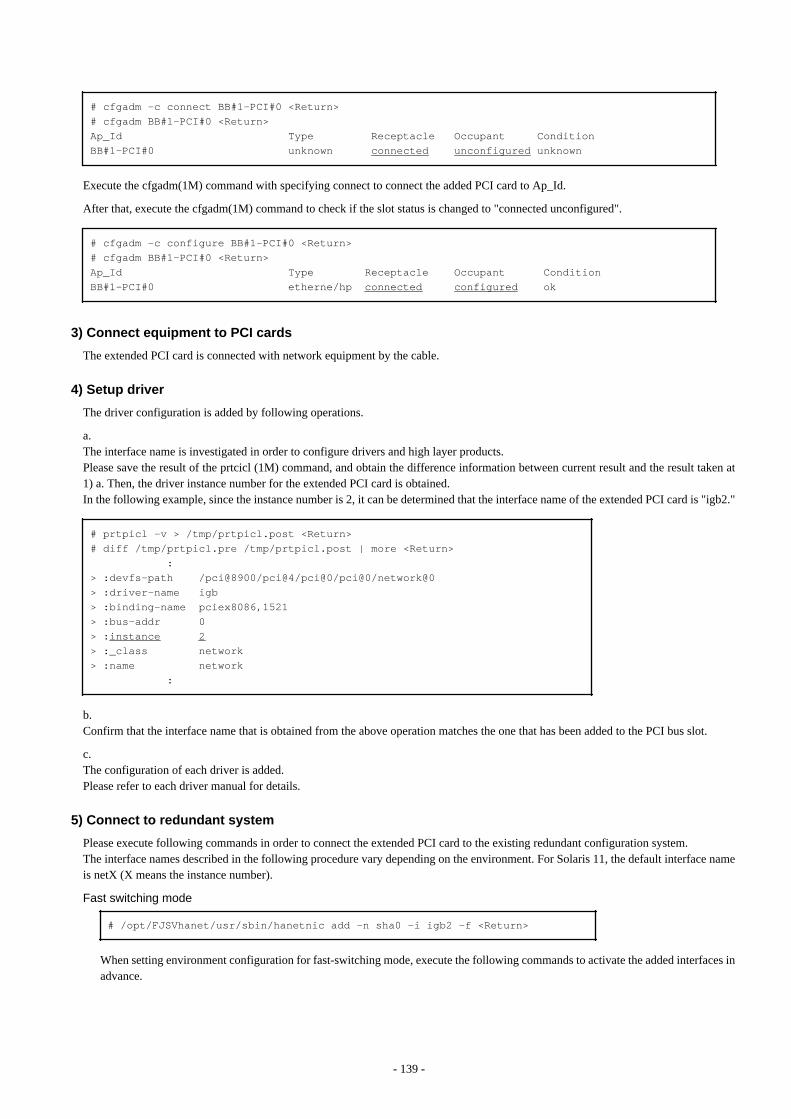
# cfgadm -c connect BB#1-PCI#0 <Return># cfgadm BB#1-PCI#0 <Return>Ap_Id Type Receptacle Occupant ConditionBB#1-PCI#0 unknown connected unconfigured unknown
Execute the cfgadm(1M) command with specifying connect to connect the added PCI card to Ap_Id.
After that, execute the cfgadm(1M) command to check if the slot status is changed to "connected unconfigured".
# cfgadm -c configure BB#1-PCI#0 <Return># cfgadm BB#1-PCI#0 <Return>Ap_Id Type Receptacle Occupant ConditionBB#1-PCI#0 etherne/hp connected configured ok
3) Connect equipment to PCI cards
The extended PCI card is connected with network equipment by the cable.
4) Setup driver
The driver configuration is added by following operations.
a.The interface name is investigated in order to configure drivers and high layer products.Please save the result of the prtcicl (1M) command, and obtain the difference information between current result and the result taken at1) a. Then, the driver instance number for the extended PCI card is obtained.In the following example, since the instance number is 2, it can be determined that the interface name of the extended PCI card is "igb2."
# prtpicl -v > /tmp/prtpicl.post <Return># diff /tmp/prtpicl.pre /tmp/prtpicl.post | more <Return> :> :devfs-path /pci@8900/pci@4/pci@0/pci@0/network@0> :driver-name igb> :binding-name pciex8086,1521> :bus-addr 0> :instance 2> :_class network> :name network :
b.Confirm that the interface name that is obtained from the above operation matches the one that has been added to the PCI bus slot.
c.The configuration of each driver is added.Please refer to each driver manual for details.
5) Connect to redundant system
Please execute following commands in order to connect the extended PCI card to the existing redundant configuration system.The interface names described in the following procedure vary depending on the environment. For Solaris 11, the default interface nameis netX (X means the instance number).
Fast switching mode # /opt/FJSVhanet/usr/sbin/hanetnic add -n sha0 -i igb2 -f <Return>
When setting environment configuration for fast-switching mode, execute the following commands to activate the added interfaces inadvance.
- 139 -

- When using IPv4 address:
- For Solaris 10
# /usr/sbin/ifconfig igb2 plumb <Return># /usr/sbin/ifconfig igb2 ipaddress netmask + broadcast + -trailers up <Return>
- For Solaris 11
# /usr/sbin/ipadm create-ip net2 <Return># /usr/sbin/ipadm create-addr -T static -a ipaddress/netmask net2/v4 <Return>
- When using IPv6 address:
- For Solaris 10
# /usr/sbin/ifconfig igb2 inet6 plumb up <Return>
- For Solaris 11
# /usr/sbin/ipadm create-ip net2 <Return># /usr/sbin/ipadm create-addr -T addrconf net2/v6 <Return>
Note
[For Solaris 10 environment]
For Fast switching mode (IPv4), the IP address specified in this section must also be set to /etc/inet/hosts and /etc/hostname.igb2.For Fast switching mode (IPv6), create /etc/hostname6.hme1igb1 as an empty file.Unless these are configured, when the system reboots, the virtual interface for Fast Switching mode cannot be activated.
GS/SURE linkage mode # /opt/FJSVhanet/usr/sbin/stphanet -n sha0 <Return># /opt/FJSVhanet/usr/sbin/hanetconfig create -n sha4 -m n -i IP_address -t igb2 <Return># /opt/FJSVhanet/usr/sbin/hanetconfig modify -n sha0 -t sha2,sha3,sha4 <Return># /opt/FJSVhanet/usr/sbin/strhanet -n sha0 <Return>
6) Switch the redundant path
Please switch an online communication path for extended communication path if needed.
4.6 Recovery Procedure from Line FailureThis section explains the recovery procedure in various modes after a line failure has occurred.
4.6.1 Recovery procedure from line failure in Fast switching modeNo special operation is required because recovery is automatically made after a line failure has occurred.
However, some applications may need to be restarted.
4.6.2 Recovery procedure from line failure in NIC switching modeThe following shows the recovery procedure from a line failure in NIC switching mode.
Some applications may need to be restarted after the recovery procedure on Redundant Line Control function.
- 140 -
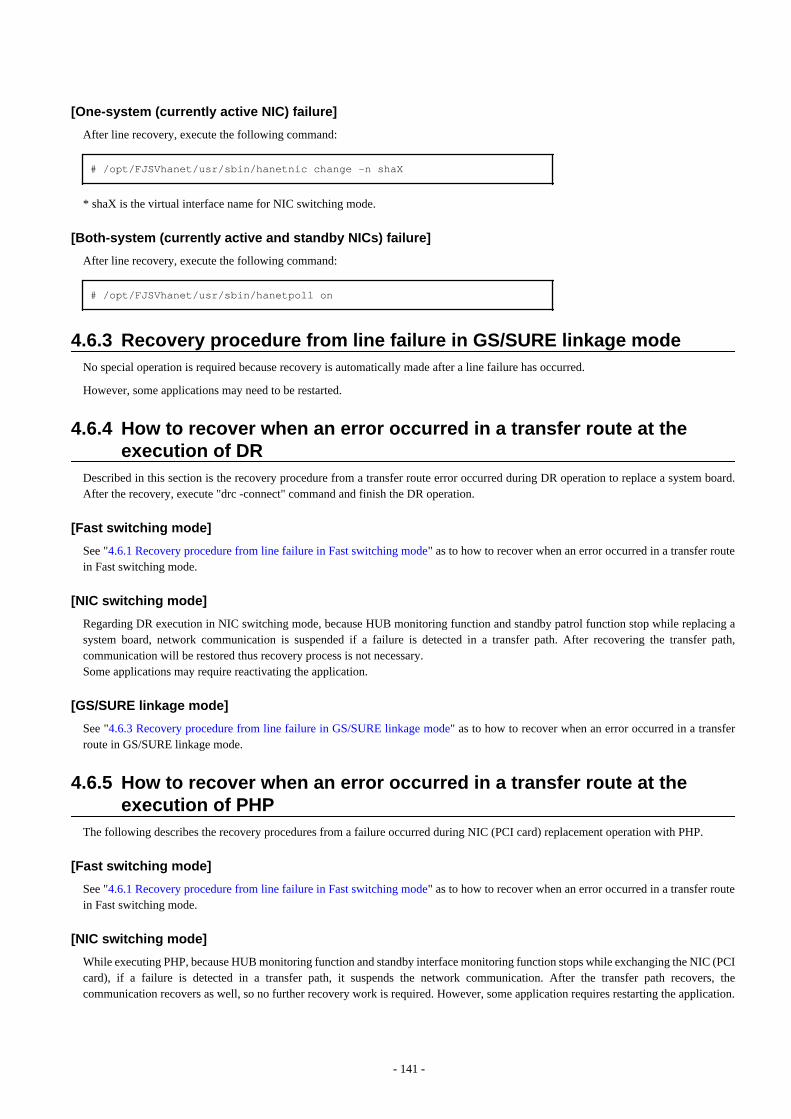
[One-system (currently active NIC) failure]
After line recovery, execute the following command:
# /opt/FJSVhanet/usr/sbin/hanetnic change -n shaX
* shaX is the virtual interface name for NIC switching mode.
[Both-system (currently active and standby NICs) failure]
After line recovery, execute the following command:
# /opt/FJSVhanet/usr/sbin/hanetpoll on
4.6.3 Recovery procedure from line failure in GS/SURE linkage modeNo special operation is required because recovery is automatically made after a line failure has occurred.
However, some applications may need to be restarted.
4.6.4 How to recover when an error occurred in a transfer route at theexecution of DR
Described in this section is the recovery procedure from a transfer route error occurred during DR operation to replace a system board.After the recovery, execute "drc -connect" command and finish the DR operation.
[Fast switching mode]
See "4.6.1 Recovery procedure from line failure in Fast switching mode" as to how to recover when an error occurred in a transfer routein Fast switching mode.
[NIC switching mode]
Regarding DR execution in NIC switching mode, because HUB monitoring function and standby patrol function stop while replacing asystem board, network communication is suspended if a failure is detected in a transfer path. After recovering the transfer path,communication will be restored thus recovery process is not necessary.Some applications may require reactivating the application.
[GS/SURE linkage mode]
See "4.6.3 Recovery procedure from line failure in GS/SURE linkage mode" as to how to recover when an error occurred in a transferroute in GS/SURE linkage mode.
4.6.5 How to recover when an error occurred in a transfer route at theexecution of PHP
The following describes the recovery procedures from a failure occurred during NIC (PCI card) replacement operation with PHP.
[Fast switching mode]
See "4.6.1 Recovery procedure from line failure in Fast switching mode" as to how to recover when an error occurred in a transfer routein Fast switching mode.
[NIC switching mode]
While executing PHP, because HUB monitoring function and standby interface monitoring function stops while exchanging the NIC (PCIcard), if a failure is detected in a transfer path, it suspends the network communication. After the transfer path recovers, thecommunication recovers as well, so no further recovery work is required. However, some application requires restarting the application.
- 141 -
[GS/SURE linkage mode]
See "4.6.3 Recovery procedure from line failure in GS/SURE linkage mode" as to how to recover when an error occurred in a transferroute in GS/SURE linkage mode.
4.7 Backing up and Restoring Configuration FilesThis section explains how to back up and restore configuration files of Redundant Line Control function.
4.7.1 Backing up Configuration FilesUse the hanetbackup command to back up configuration files.
For details about this command, see Section "7.12 hanetbackup Command".
4.7.2 Restoring Configuration FilesUse the hanetrestore command to restore configuration files.
For details about this command, see Section "7.13 hanetrestore Command".
After executing this command, restart the system immediately. The system will not operate as defined in the configuration file, unless youreboot the system.
- 142 -
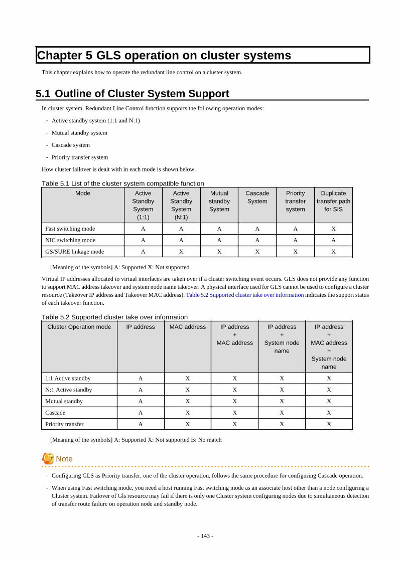
Chapter 5 GLS operation on cluster systemsThis chapter explains how to operate the redundant line control on a cluster system.
5.1 Outline of Cluster System SupportIn cluster system, Redundant Line Control function supports the following operation modes:
- Active standby system (1:1 and N:1)
- Mutual standby system
- Cascade system
- Priority transfer system
How cluster failover is dealt with in each mode is shown below.
Table 5.1 List of the cluster system compatible function
Mode ActiveStandbySystem
(1:1)
ActiveStandbySystem(N:1)
MutualstandbySystem
CascadeSystem
Prioritytransfersystem
Duplicatetransfer path
for SIS
Fast switching mode A A A A A X
NIC switching mode A A A A A A
GS/SURE linkage mode A X X X X X
[Meaning of the symbols] A: Supported X: Not supported
Virtual IP addresses allocated to virtual interfaces are taken over if a cluster switching event occurs. GLS does not provide any functionto support MAC address takeover and system node name takeover. A physical interface used for GLS cannot be used to configure a clusterresource (Takeover IP address and Takeover MAC address). Table 5.2 Supported cluster take over information indicates the support statusof each takeover function.
Table 5.2 Supported cluster take over information
Cluster Operation mode IP address MAC address IP address+
MAC address
IP address+
System nodename
IP address+
MAC address+
System nodename
1:1 Active standby A X X X X
N:1 Active standby A X X X X
Mutual standby A X X X X
Cascade A X X X X
Priority transfer A X X X X
[Meaning of the symbols] A: Supported X: Not supported B: No match
Note
- Configuring GLS as Priority transfer, one of the cluster operation, follows the same procedure for configuring Cascade operation.
- When using Fast switching mode, you need a host running Fast switching mode as an associate host other than a node configuring aCluster system. Failover of Gls resource may fail if there is only one Cluster system configuring nodes due to simultaneous detectionof transfer route failure on operation node and standby node.
- 143 -
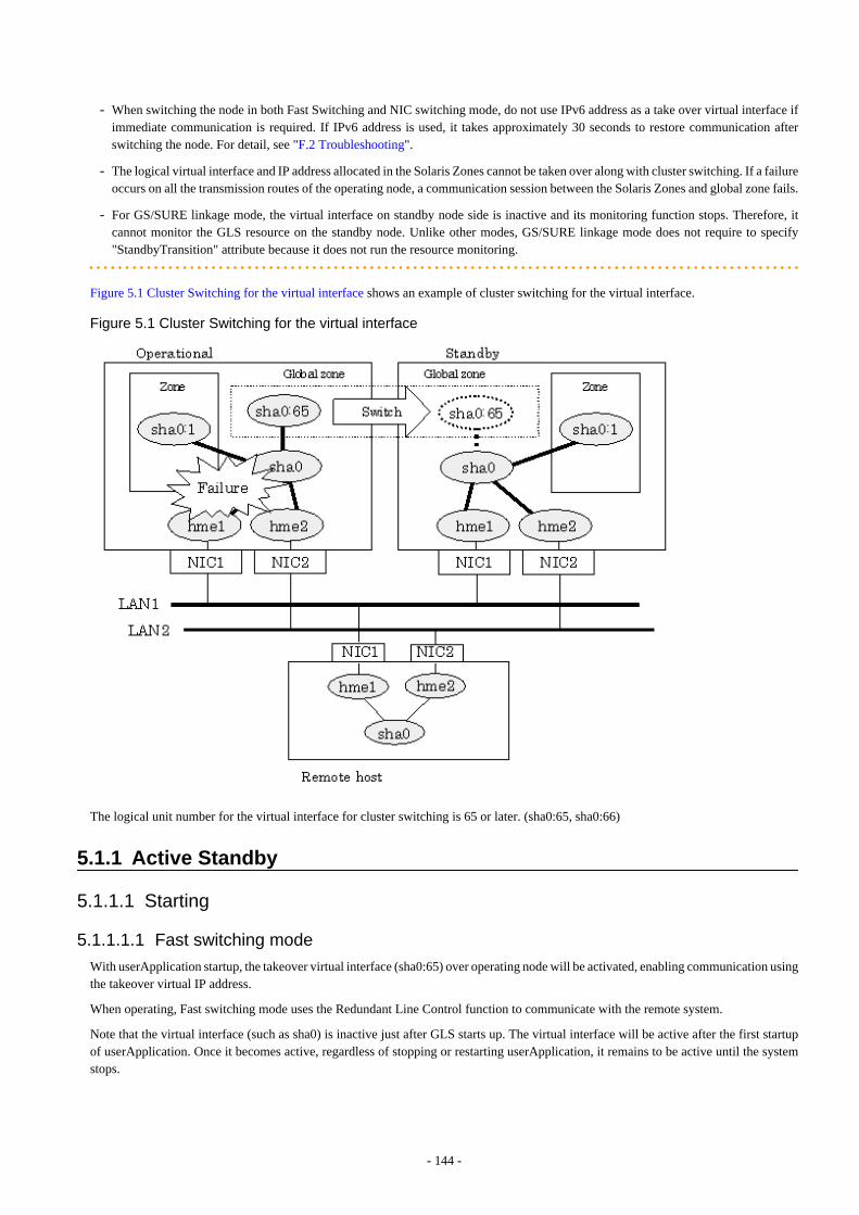
- When switching the node in both Fast Switching and NIC switching mode, do not use IPv6 address as a take over virtual interface ifimmediate communication is required. If IPv6 address is used, it takes approximately 30 seconds to restore communication afterswitching the node. For detail, see "F.2 Troubleshooting".
- The logical virtual interface and IP address allocated in the Solaris Zones cannot be taken over along with cluster switching. If a failureoccurs on all the transmission routes of the operating node, a communication session between the Solaris Zones and global zone fails.
- For GS/SURE linkage mode, the virtual interface on standby node side is inactive and its monitoring function stops. Therefore, itcannot monitor the GLS resource on the standby node. Unlike other modes, GS/SURE linkage mode does not require to specify"StandbyTransition" attribute because it does not run the resource monitoring.
Figure 5.1 Cluster Switching for the virtual interface shows an example of cluster switching for the virtual interface.
Figure 5.1 Cluster Switching for the virtual interface
The logical unit number for the virtual interface for cluster switching is 65 or later. (sha0:65, sha0:66)
5.1.1 Active Standby
5.1.1.1 Starting
5.1.1.1.1 Fast switching mode
With userApplication startup, the takeover virtual interface (sha0:65) over operating node will be activated, enabling communication usingthe takeover virtual IP address.
When operating, Fast switching mode uses the Redundant Line Control function to communicate with the remote system.
Note that the virtual interface (such as sha0) is inactive just after GLS starts up. The virtual interface will be active after the first startupof userApplication. Once it becomes active, regardless of stopping or restarting userApplication, it remains to be active until the systemstops.
- 144 -
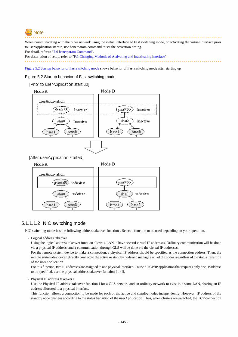
Note
When communicating with the other network using the virtual interface of Fast switching mode, or activating the virtual interface priorto userApplication startup, use hanetparam command to set the activation timing. For detail, refer to "7.6 hanetparam Command".For description of setup, refer to "F.1 Changing Methods of Activating and Inactivating Interface".
Figure 5.2 Startup behavior of Fast switching mode shows behavior of Fast switching mode after starting up
Figure 5.2 Startup behavior of Fast switching mode
5.1.1.1.2 NIC switching mode
NIC switching mode has the following address takeover functions. Select a function to be used depending on your operation.
- Logical address takeoverUsing the logical address takeover function allows a LAN to have several virtual IP addresses. Ordinary communication will be donevia a physical IP address, and a communication through GLS will be done via the virtual IP addresses.For the remote system device to make a connection, a physical IP address should be specified as the connection address. Then, theremote system device can directly connect to the active or standby node and manage each of the nodes regardless of the status transitionof the userApplication.For this function, two IP addresses are assigned to one physical interface. To use a TCP/IP application that requires only one IP addressto be specified, use the physical address takeover function I or II.
- Physical IP address takeover IUse the Physical IP address takeover function I for a GLS network and an ordinary network to exist in a same LAN, sharing an IPaddress allocated to a physical interface.This function allows a connection to be made for each of the active and standby nodes independently. However, IP address of thestandby node changes according to the status transition of the userApplication. Thus, when clusters are switched, the TCP connection
- 145 -
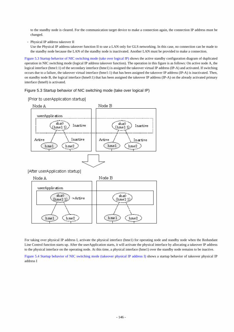
to the standby node is cleared. For the communication target device to make a connection again, the connection IP address must bechanged.
- Physical IP address takeover IIUse the Physical IP address takeover function II to use a LAN only for GLS networking. In this case, no connection can be made tothe standby node because the LAN of the standby node is inactivated. Another LAN must be provided to make a connection.
Figure 5.3 Startup behavior of NIC switching mode (take over logical IP) shows the active standby configuration diagram of duplicatedoperation in NIC switching mode (logical IP address takeover function). The operation in this figure is as follows: On active node A, thelogical interface (hme1:1) of the secondary interface (hme1) is assigned the takeover virtual IP address (IP-A) and activated. If switchingoccurs due to a failure, the takeover virtual interface (hme1:1) that has been assigned the takeover IP address (IP-A) is inactivated. Then,on standby node B, the logical interface (hme0:1) that has been assigned the takeover IP address (IP-A) on the already activated primaryinterface (hme0) is activated.
Figure 5.3 Startup behavior of NIC switching mode (take over logical IP)
For taking over physical IP address I, activate the physical interface (hme1) for operating node and standby node when the RedundantLine Control function starts up. After the userApplication starts, it will activate the physical interface by allocating a takeover IP addressto the physical interface on the operating node. At this time, a physical interface (hme1) over the standby node remains to be inactive.
Figure 5.4 Startup behavior of NIC switching mode (takeover physical IP address I) shows a startup behavior of takeover physical IPaddress I
- 146 -

Figure 5.4 Startup behavior of NIC switching mode (takeover physical IP address I)
For taking over physical IP address II, it does not activate the physical interface (hme1) for both operating node and standby node whenRedundant Line Control function starts up. Instead it allocates a takeover IP address to the physical interface (hme1) on the operating nodeand then it activates the physical interface. In this case, the physical interface (hme1) for standby node remains inactive.
Figure 5.5 Startup behavior of NIC switching mode (takeover physical IP address II) shows a startup behavior of the takeover physical IPaddress II
- 147 -
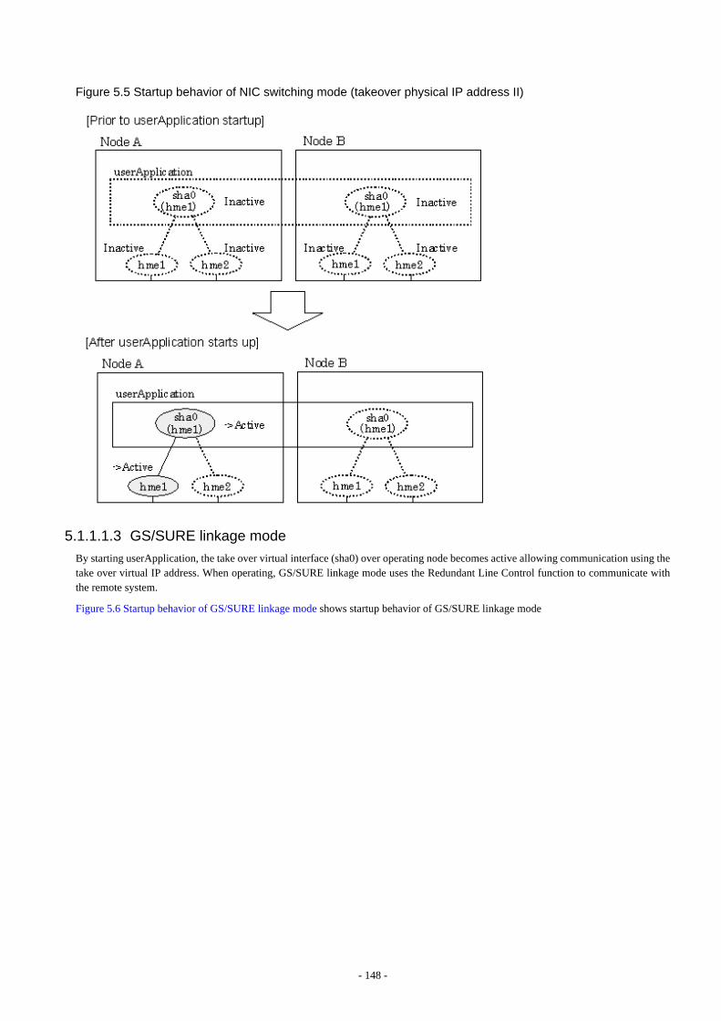
Figure 5.5 Startup behavior of NIC switching mode (takeover physical IP address II)
5.1.1.1.3 GS/SURE linkage mode
By starting userApplication, the take over virtual interface (sha0) over operating node becomes active allowing communication using thetake over virtual IP address. When operating, GS/SURE linkage mode uses the Redundant Line Control function to communicate withthe remote system.
Figure 5.6 Startup behavior of GS/SURE linkage mode shows startup behavior of GS/SURE linkage mode
- 148 -
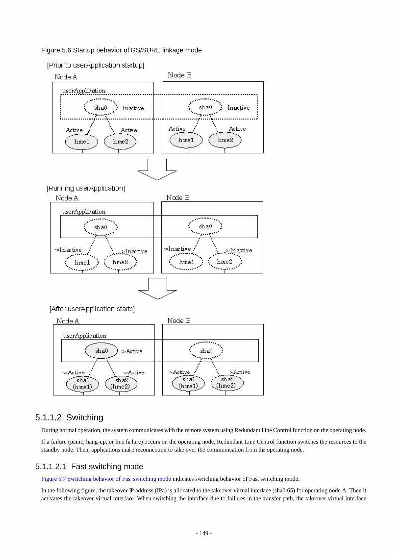
Figure 5.6 Startup behavior of GS/SURE linkage mode
5.1.1.2 SwitchingDuring normal operation, the system communicates with the remote system using Redundant Line Control function on the operating node.
If a failure (panic, hang-up, or line failure) occurs on the operating node, Redundant Line Control function switches the resources to thestandby node. Then, applications make reconnection to take over the communication from the operating node.
5.1.1.2.1 Fast switching mode
Figure 5.7 Switching behavior of Fast switching mode indicates switching behavior of Fast switching mode.
In the following figure, the takeover IP address (IPa) is allocated to the takeover virtual interface (sha0:65) for operating node A. Then itactivates the takeover virtual interface. When switching the interface due to failures in the transfer path, the takeover virtual interface
- 149 -

(sha0:65) for operating node A becomes inactive. Then in standby node B, the takeover virtual interface (sha0:65), which has allocatedthe takeover IP address (IPa) becomes active. Note that the virtual interface (sha0) in node A remains unchanged.
Figure 5.7 Switching behavior of Fast switching mode
5.1.1.2.2 NIC switching mode
Figure 5.8 Switching behavior of NIC switching mode (takeover logical IP) illustrates switching behavior of NIC switching mode (logicalIP address takeover function).
In the following figure, the takeover virtual IP address (IPa) in the operating node A is allocated to the logical interface (hme2.1) for thesecondary interface. Once IPa is allocated, the logical interface (hme2.1) for the secondary interface turns into activate state.
When switching the node due to failure in the transfer routes, NIC switching mode inactivates the logical virtual interface which hasallocated the takeover IP address (IPa) in the operating node A. Then it allocates the takeover IP address to the primary interface (hme1)and finally activates the logical interface (hme1:1).
- 150 -
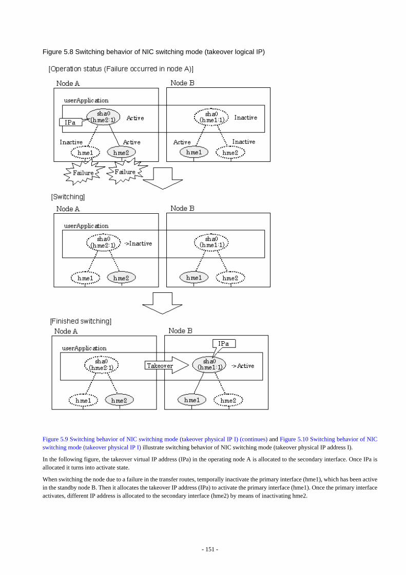
Figure 5.8 Switching behavior of NIC switching mode (takeover logical IP)
Figure 5.9 Switching behavior of NIC switching mode (takeover physical IP I) (continues) and Figure 5.10 Switching behavior of NICswitching mode (takeover physical IP I) illustrate switching behavior of NIC switching mode (takeover physical IP address I).
In the following figure, the takeover virtual IP address (IPa) in the operating node A is allocated to the secondary interface. Once IPa isallocated it turns into activate state.
When switching the node due to a failure in the transfer routes, temporally inactivate the primary interface (hme1), which has been activein the standby node B. Then it allocates the takeover IP address (IPa) to activate the primary interface (hme1). Once the primary interfaceactivates, different IP address is allocated to the secondary interface (hme2) by means of inactivating hme2.
- 151 -
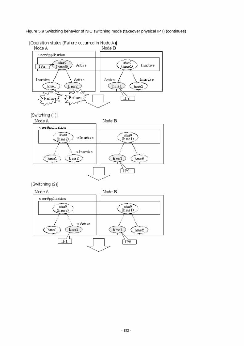
Figure 5.9 Switching behavior of NIC switching mode (takeover physical IP I) (continues)
- 152 -
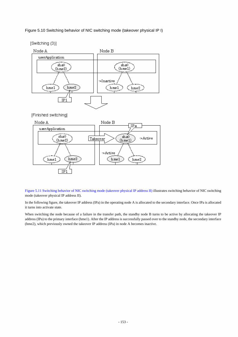
Figure 5.10 Switching behavior of NIC switching mode (takeover physical IP I)
Figure 5.11 Switching behavior of NIC switching mode (takeover physical IP address II) illustrates switching behavior of NIC switchingmode (takeover physical IP address II).
In the following figure, the takeover IP address (IPa) in the operating node A is allocated to the secondary interface. Once IPa is allocatedit turns into activate state.
When switching the node because of a failure in the transfer path, the standby node B turns to be active by allocating the takeover IPaddress (IPa) to the primary interface (hme1). After the IP address is successfully passed over to the standby node, the secondary interface(hme2), which previously owned the takeover IP address (IPa) in node A becomes inactive.
- 153 -
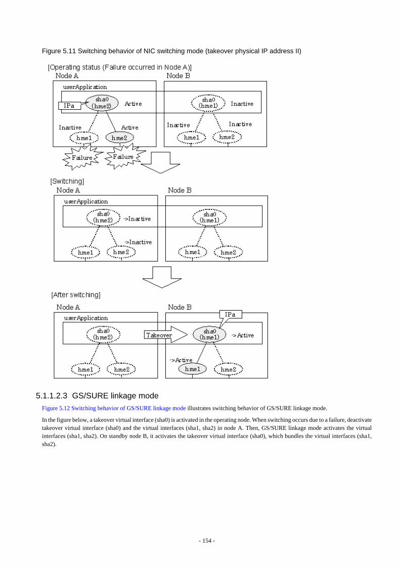
Figure 5.11 Switching behavior of NIC switching mode (takeover physical IP address II)
5.1.1.2.3 GS/SURE linkage mode
Figure 5.12 Switching behavior of GS/SURE linkage mode illustrates switching behavior of GS/SURE linkage mode.
In the figure below, a takeover virtual interface (sha0) is activated in the operating node. When switching occurs due to a failure, deactivatetakeover virtual interface (sha0) and the virtual interfaces (sha1, sha2) in node A. Then, GS/SURE linkage mode activates the virtualinterfaces (sha1, sha2). On standby node B, it activates the takeover virtual interface (sha0), which bundles the virtual interfaces (sha1,sha2).
- 154 -
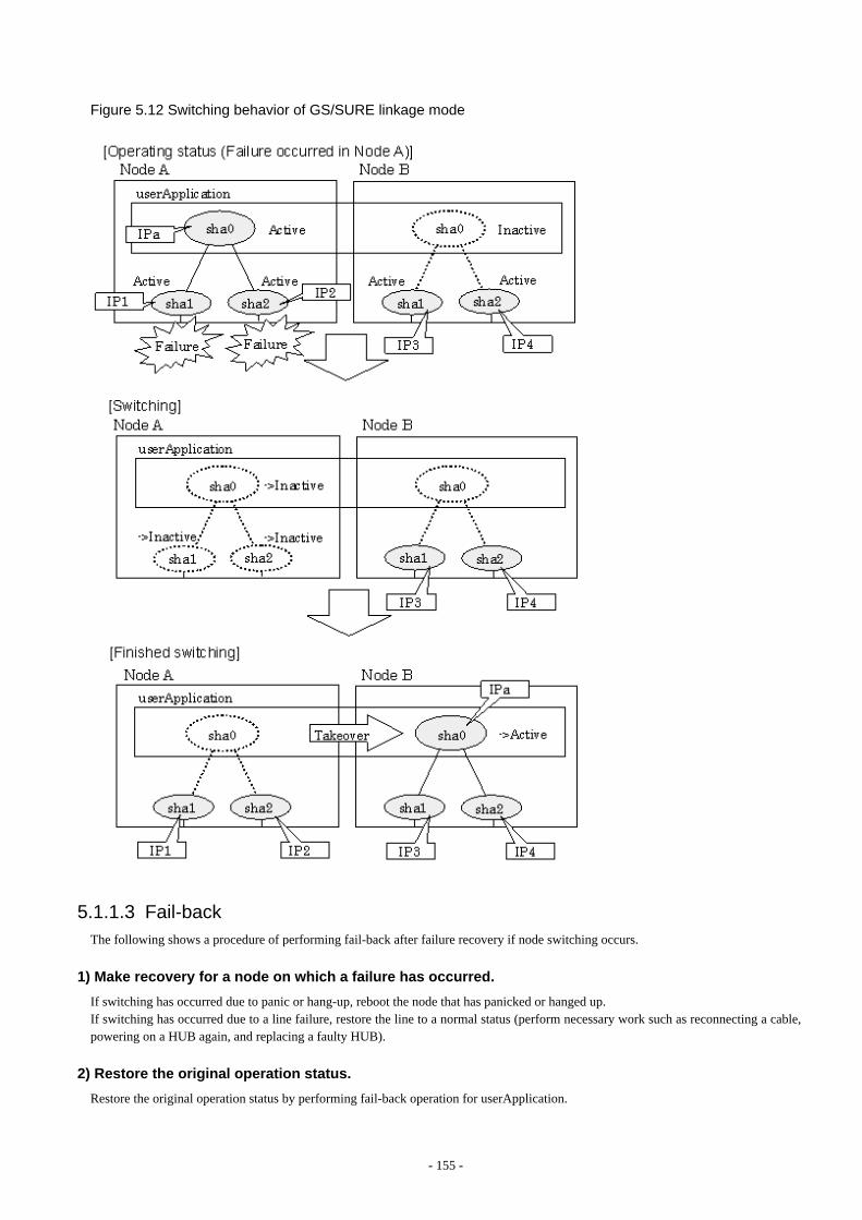
Figure 5.12 Switching behavior of GS/SURE linkage mode
5.1.1.3 Fail-backThe following shows a procedure of performing fail-back after failure recovery if node switching occurs.
1) Make recovery for a node on which a failure has occurred.
If switching has occurred due to panic or hang-up, reboot the node that has panicked or hanged up.If switching has occurred due to a line failure, restore the line to a normal status (perform necessary work such as reconnecting a cable,powering on a HUB again, and replacing a faulty HUB).
2) Restore the original operation status.
Restore the original operation status by performing fail-back operation for userApplication.
- 155 -

5.1.1.4 Stopping
5.1.1.4.1 Fast switching mode
Figure 5.13 Stopping behavior of Fast switching mode illustrates stopping process of userApplication.
Figure 5.13 Stopping behavior of Fast switching mode
5.1.1.4.2 NIC switching mode
Figure 5.14 Stopping process of NIC switching mode (logical IP takeover) illustrates stopping process of userApplication for logical IPtakeover.
- 156 -
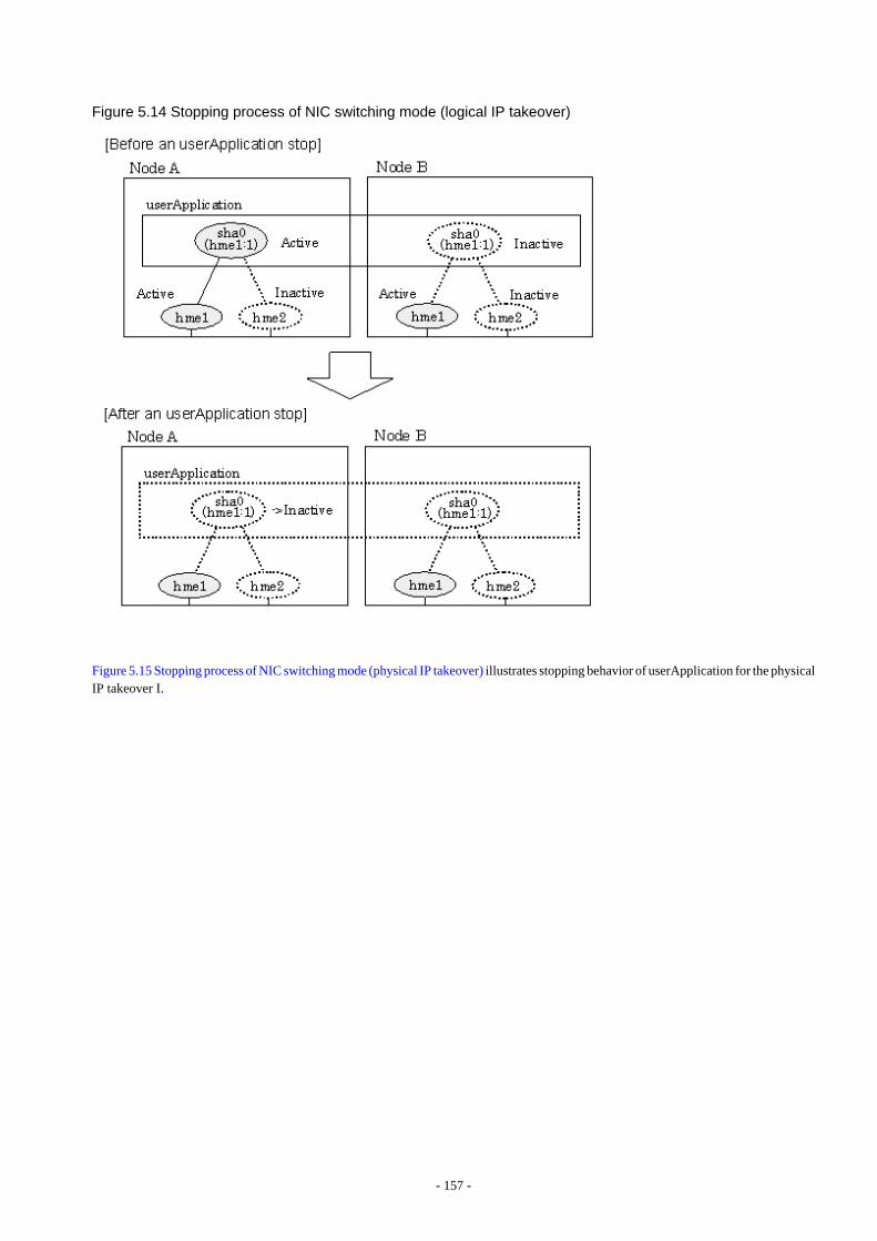
Figure 5.14 Stopping process of NIC switching mode (logical IP takeover)
Figure 5.15 Stopping process of NIC switching mode (physical IP takeover) illustrates stopping behavior of userApplication for the physicalIP takeover I.
- 157 -
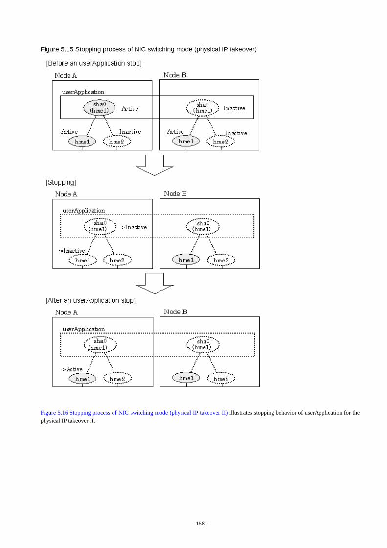
Figure 5.15 Stopping process of NIC switching mode (physical IP takeover)
Figure 5.16 Stopping process of NIC switching mode (physical IP takeover II) illustrates stopping behavior of userApplication for thephysical IP takeover II.
- 158 -

Figure 5.16 Stopping process of NIC switching mode (physical IP takeover II)
5.1.1.4.3 GS/SURE linkage mode
Figure 5.17 Stopping process of GS/SURE linkage mode illustrates stopping behavior of userApplication.
- 159 -
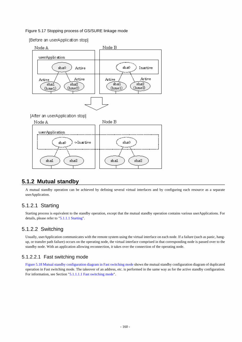
Figure 5.17 Stopping process of GS/SURE linkage mode
5.1.2 Mutual standbyA mutual standby operation can be achieved by defining several virtual interfaces and by configuring each resource as a separateuserApplication.
5.1.2.1 StartingStarting process is equivalent to the standby operation, except that the mutual standby operation contains various userApplications. Fordetails, please refer to "5.1.1.1 Starting".
5.1.2.2 SwitchingUsually, userApplication communicates with the remote system using the virtual interface on each node. If a failure (such as panic, hang-up, or transfer path failure) occurs on the operating node, the virtual interface comprised in that corresponding node is passed over to thestandby node. With an application allowing reconnection, it takes over the connection of the operating node.
5.1.2.2.1 Fast switching mode
Figure 5.18 Mutual standby configuration diagram in Fast switching mode shows the mutual standby configuration diagram of duplicatedoperation in Fast switching mode. The takeover of an address, etc. is performed in the same way as for the active standby configuration.For information, see Section "5.1.1.1.1 Fast switching mode".
- 160 -
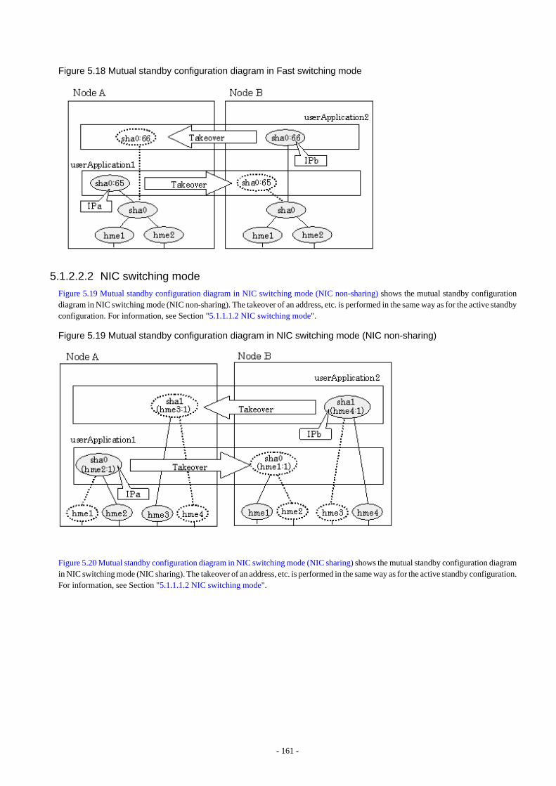
Figure 5.18 Mutual standby configuration diagram in Fast switching mode
5.1.2.2.2 NIC switching mode
Figure 5.19 Mutual standby configuration diagram in NIC switching mode (NIC non-sharing) shows the mutual standby configurationdiagram in NIC switching mode (NIC non-sharing). The takeover of an address, etc. is performed in the same way as for the active standbyconfiguration. For information, see Section "5.1.1.1.2 NIC switching mode".
Figure 5.19 Mutual standby configuration diagram in NIC switching mode (NIC non-sharing)
Figure 5.20 Mutual standby configuration diagram in NIC switching mode (NIC sharing) shows the mutual standby configuration diagramin NIC switching mode (NIC sharing). The takeover of an address, etc. is performed in the same way as for the active standby configuration.For information, see Section "5.1.1.1.2 NIC switching mode".
- 161 -
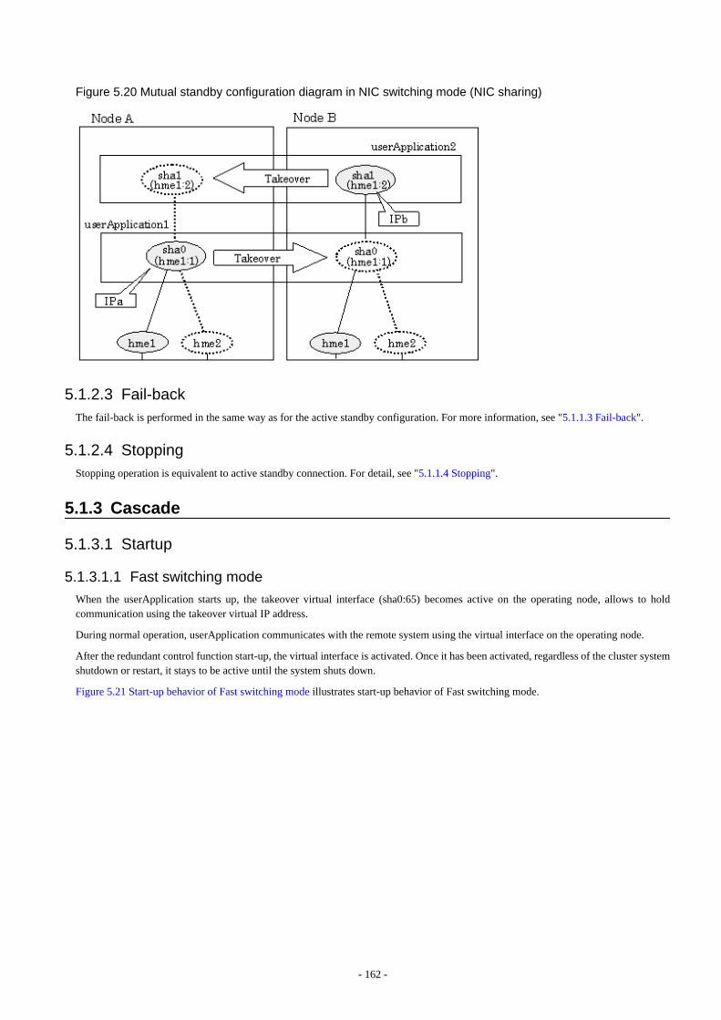
Figure 5.20 Mutual standby configuration diagram in NIC switching mode (NIC sharing)
5.1.2.3 Fail-backThe fail-back is performed in the same way as for the active standby configuration. For more information, see "5.1.1.3 Fail-back".
5.1.2.4 StoppingStopping operation is equivalent to active standby connection. For detail, see "5.1.1.4 Stopping".
5.1.3 Cascade
5.1.3.1 Startup
5.1.3.1.1 Fast switching mode
When the userApplication starts up, the takeover virtual interface (sha0:65) becomes active on the operating node, allows to holdcommunication using the takeover virtual IP address.
During normal operation, userApplication communicates with the remote system using the virtual interface on the operating node.
After the redundant control function start-up, the virtual interface is activated. Once it has been activated, regardless of the cluster systemshutdown or restart, it stays to be active until the system shuts down.
Figure 5.21 Start-up behavior of Fast switching mode illustrates start-up behavior of Fast switching mode.
- 162 -
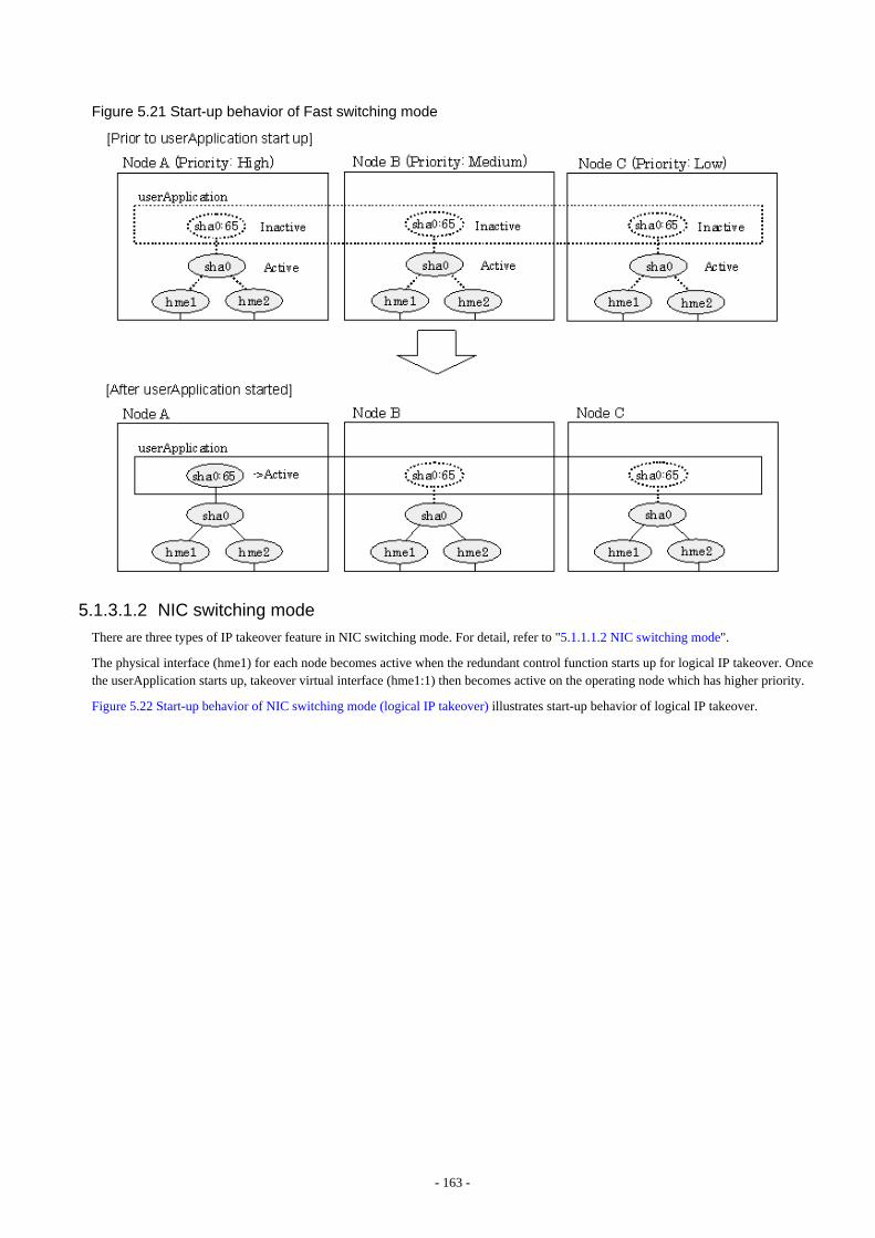
Figure 5.21 Start-up behavior of Fast switching mode
5.1.3.1.2 NIC switching mode
There are three types of IP takeover feature in NIC switching mode. For detail, refer to "5.1.1.1.2 NIC switching mode".
The physical interface (hme1) for each node becomes active when the redundant control function starts up for logical IP takeover. Oncethe userApplication starts up, takeover virtual interface (hme1:1) then becomes active on the operating node which has higher priority.
Figure 5.22 Start-up behavior of NIC switching mode (logical IP takeover) illustrates start-up behavior of logical IP takeover.
- 163 -
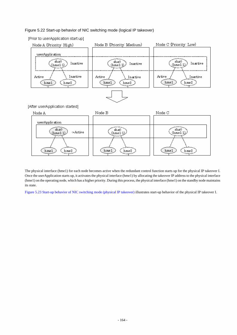
Figure 5.22 Start-up behavior of NIC switching mode (logical IP takeover)
The physical interface (hme1) for each node becomes active when the redundant control function starts up for the physical IP takeover I.Once the userApplication starts up, it activates the physical interface (hme1) by allocating the takeover IP address to the physical interface(hme1) on the operating node, which has a higher priority. During this process, the physical interface (hme1) on the standby node maintainsits state.
Figure 5.23 Start-up behavior of NIC switching mode (physical IP takeover) illustrates start-up behavior of the physical IP takeover I.
- 164 -
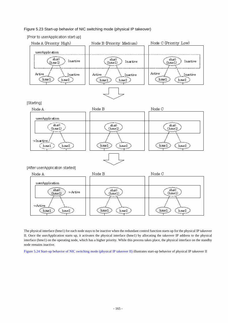
Figure 5.23 Start-up behavior of NIC switching mode (physical IP takeover)
The physical interface (hme1) for each node stays to be inactive when the redundant control function starts up for the physical IP takeoverII. Once the userApplication starts up, it activates the physical interface (hme1) by allocating the takeover IP address to the physicalinterface (hme1) on the operating node, which has a higher priority. While this process takes place, the physical interface on the standbynode remains inactive.
Figure 5.24 Start-up behavior of NIC switching mode (physical IP takeover II) illustrates start-up behavior of physical IP takeover II
- 165 -
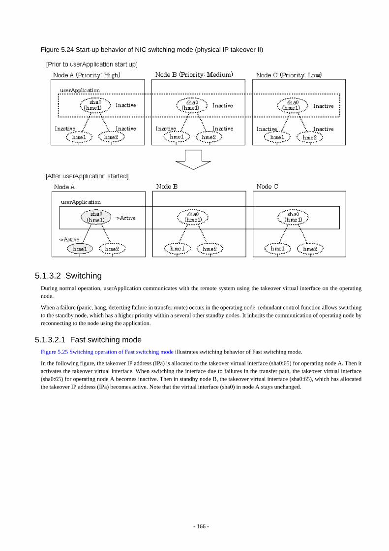
Figure 5.24 Start-up behavior of NIC switching mode (physical IP takeover II)
5.1.3.2 SwitchingDuring normal operation, userApplication communicates with the remote system using the takeover virtual interface on the operatingnode.
When a failure (panic, hang, detecting failure in transfer route) occurs in the operating node, redundant control function allows switchingto the standby node, which has a higher priority within a several other standby nodes. It inherits the communication of operating node byreconnecting to the node using the application.
5.1.3.2.1 Fast switching mode
Figure 5.25 Switching operation of Fast switching mode illustrates switching behavior of Fast switching mode.
In the following figure, the takeover IP address (IPa) is allocated to the takeover virtual interface (sha0:65) for operating node A. Then itactivates the takeover virtual interface. When switching the interface due to failures in the transfer path, the takeover virtual interface(sha0:65) for operating node A becomes inactive. Then in standby node B, the takeover virtual interface (sha0:65), which has allocatedthe takeover IP address (IPa) becomes active. Note that the virtual interface (sha0) in node A stays unchanged.
- 166 -
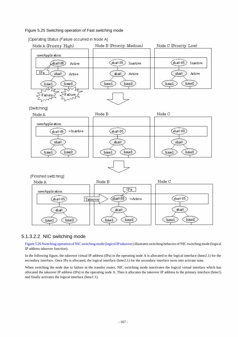
Figure 5.25 Switching operation of Fast switching mode
5.1.3.2.2 NIC switching mode
Figure 5.26 Switching operation of NIC switching mode (logical IP takeover) illustrates switching behavior of NIC switching mode (logicalIP address takeover function).
In the following figure, the takeover virtual IP address (IPa) in the operating node A is allocated to the logical interface (hme2.1) for thesecondary interface. Once IPa is allocated, the logical interface (hme2.1) for the secondary interface turns into activate state.
When switching the node due to failure in the transfer routes, NIC switching mode inactivates the logical virtual interface which hasallocated the takeover IP address (IPa) in the operating node A. Then it allocates the takeover IP address to the primary interface (hme1)and finally activates the logical interface (hme1:1).
- 167 -

Figure 5.26 Switching operation of NIC switching mode (logical IP takeover)
Figure 5.27 Switching operation of NIC switching mode (physical IP takeover I) (continues) and Figure 5.28 Switching operation of NICswitching mode (physical IP takeover I) illustrate switching behavior of NIC switching mode (takeover physical IP address I).
In the following figure, the takeover virtual IP address (IPa) in the operating node A is allocated to the secondary interface. Once IPa isallocated it turns into activate state.
When switching the node due to a failure in the transfer routes, temporally inactivate the primary interface (hme1), which has been activein the standby node B. Then it allocates the takeover IP address (IPa) to activate the primary interface (hme1). Once the primary interfaceactivates, different IP address is allocated to the secondary interface (hme2) by means of inactivating hme2.
- 168 -
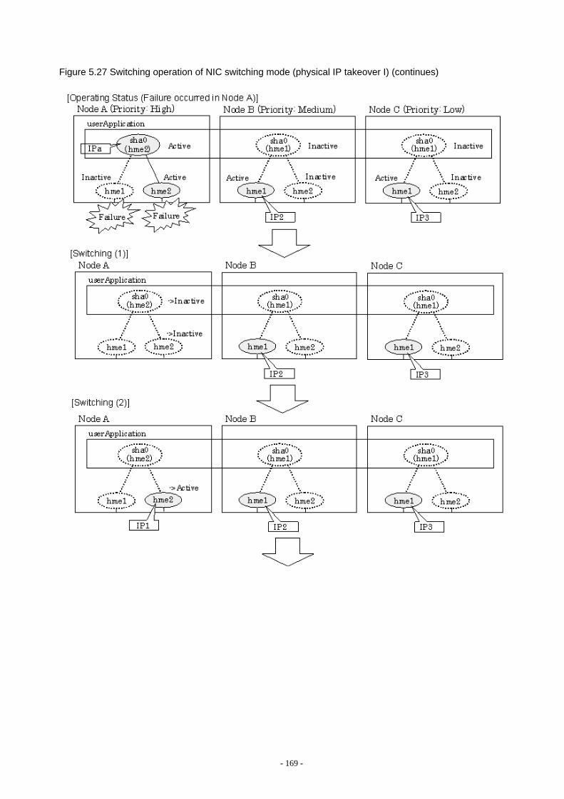
Figure 5.27 Switching operation of NIC switching mode (physical IP takeover I) (continues)
- 169 -
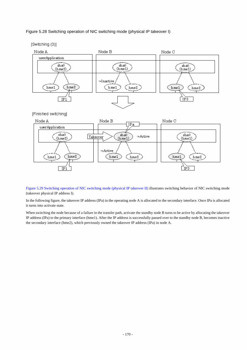
Figure 5.28 Switching operation of NIC switching mode (physical IP takeover I)
Figure 5.29 Switching operation of NIC switching mode (physical IP takeover II) illustrates switching behavior of NIC switching mode(takeover physical IP address I).
In the following figure, the takeover IP address (IPa) in the operating node A is allocated to the secondary interface. Once IPa is allocatedit turns into activate state.
When switching the node because of a failure in the transfer path, activate the standby node B turns to be active by allocating the takeoverIP address (IPa) to the primary interface (hme1). After the IP address is successfully passed over to the standby node B, becomes inactivethe secondary interface (hme2), which previously owned the takeover IP address (IPa) in node A.
- 170 -
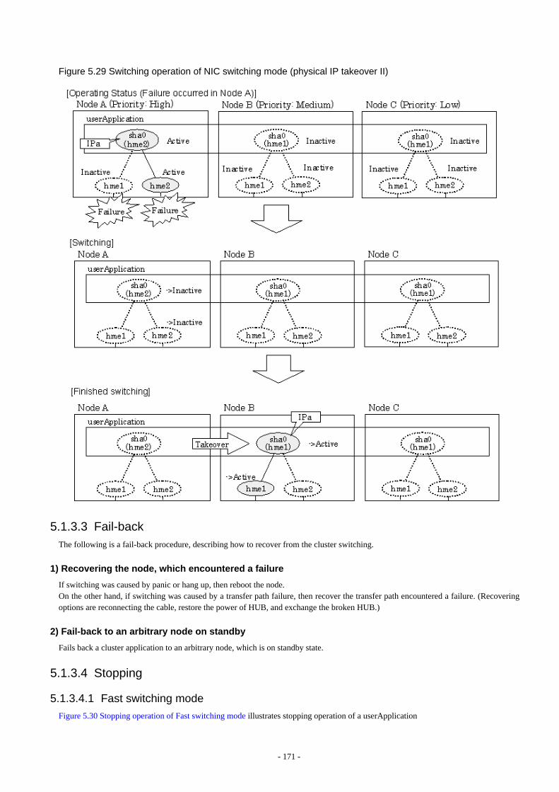
Figure 5.29 Switching operation of NIC switching mode (physical IP takeover II)
5.1.3.3 Fail-backThe following is a fail-back procedure, describing how to recover from the cluster switching.
1) Recovering the node, which encountered a failure
If switching was caused by panic or hang up, then reboot the node. On the other hand, if switching was caused by a transfer path failure, then recover the transfer path encountered a failure. (Recoveringoptions are reconnecting the cable, restore the power of HUB, and exchange the broken HUB.)
2) Fail-back to an arbitrary node on standby
Fails back a cluster application to an arbitrary node, which is on standby state.
5.1.3.4 Stopping
5.1.3.4.1 Fast switching mode
Figure 5.30 Stopping operation of Fast switching mode illustrates stopping operation of a userApplication
- 171 -
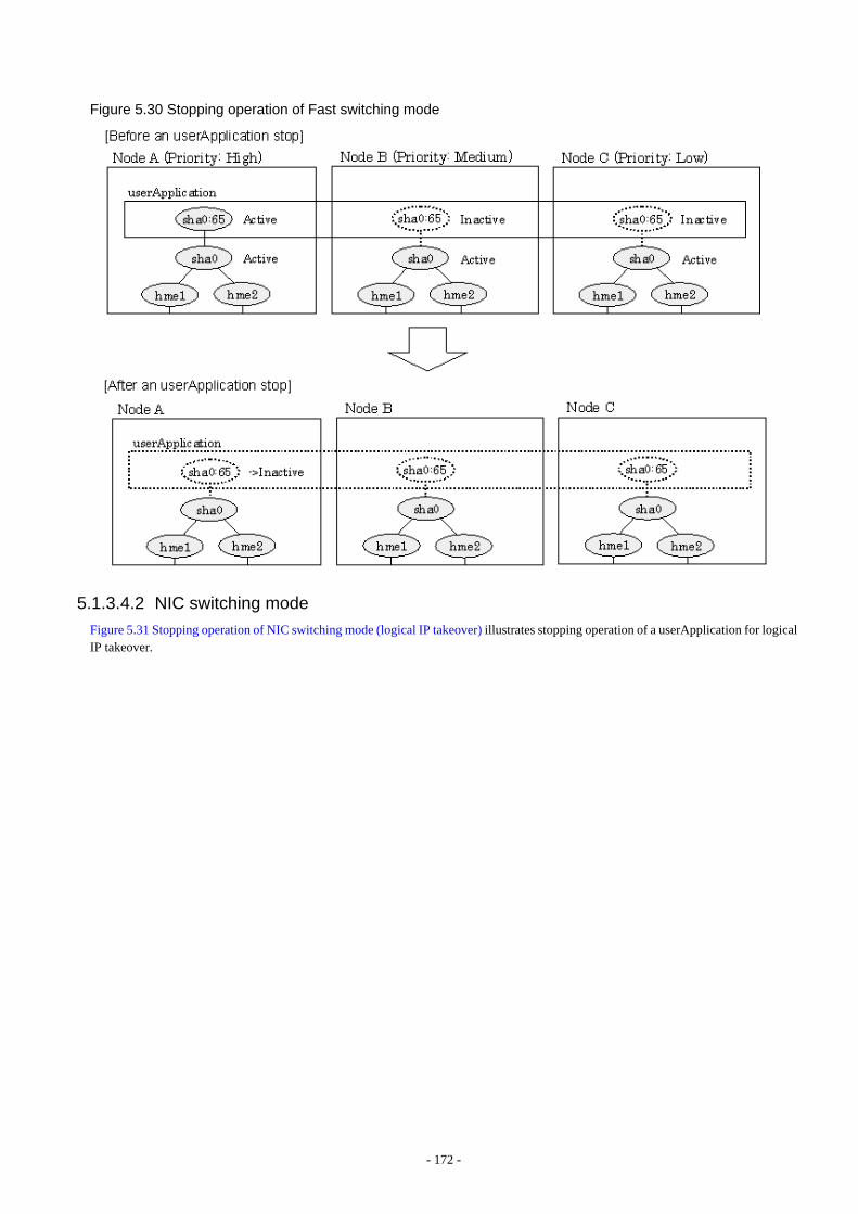
Figure 5.30 Stopping operation of Fast switching mode
5.1.3.4.2 NIC switching mode
Figure 5.31 Stopping operation of NIC switching mode (logical IP takeover) illustrates stopping operation of a userApplication for logicalIP takeover.
- 172 -
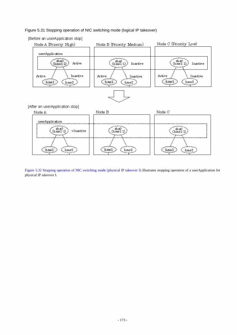
Figure 5.31 Stopping operation of NIC switching mode (logical IP takeover)
Figure 5.32 Stopping operation of NIC switching mode (physical IP takeover I) illustrates stopping operation of a userApplication forphysical IP takeover I.
- 173 -
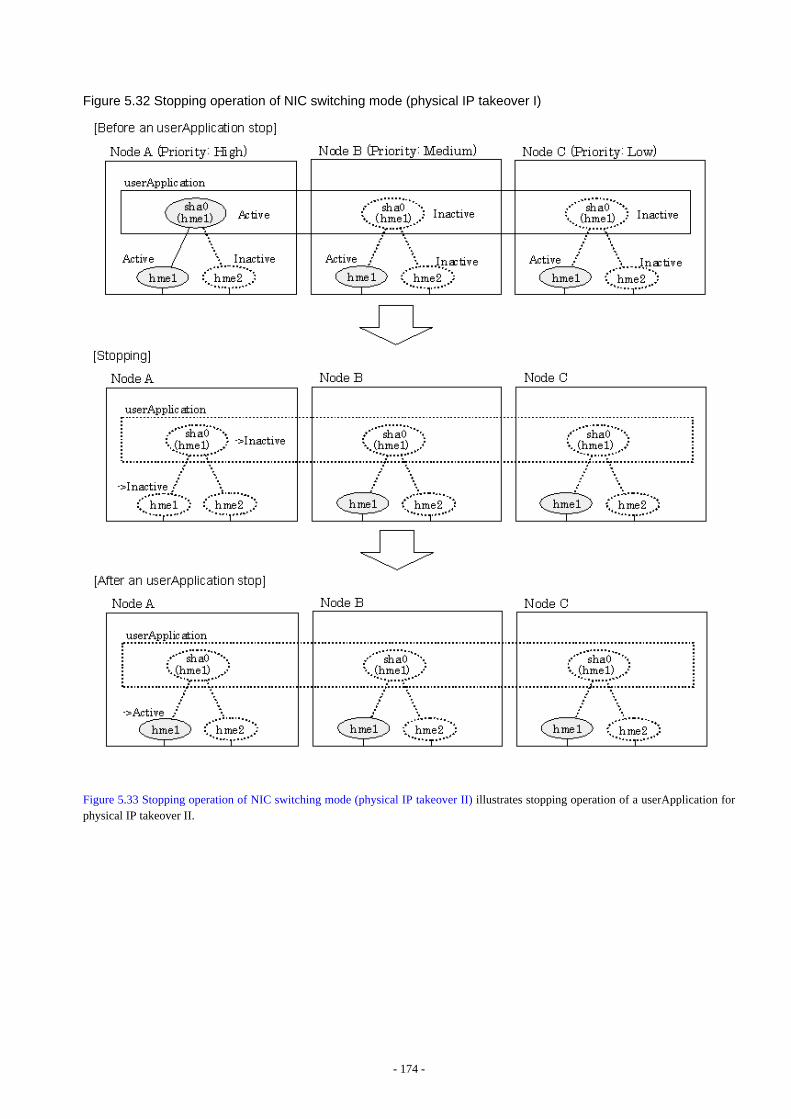
Figure 5.32 Stopping operation of NIC switching mode (physical IP takeover I)
Figure 5.33 Stopping operation of NIC switching mode (physical IP takeover II) illustrates stopping operation of a userApplication forphysical IP takeover II.
- 174 -
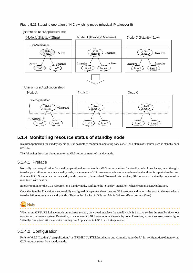
Figure 5.33 Stopping operation of NIC switching mode (physical IP takeover II)
5.1.4 Monitoring resource status of standby nodeIn a userApplication for standby operation, it is possible to monitor an operating node as well as a status of resource used in standby nodeof GLS.
The following describes about monitoring GLS resource status of standby node.
5.1.4.1 PrefaceNormally, a userApplication for standby operation does not monitor GLS resource status for standby node. In such case, even though atransfer path failure occurs in a standby node, the erroneous GLS resource remains to be unreleased and nothing is reported to the user.As a result, GLS resource error in standby node remains to be unsolved. To avoid this problem, GLS resource for standby node must bemonitored with caution.
In order to monitor the GLS resource for a standby node, configure the "Standby Transition" when creating a userApplication.
Once the Standby Transition is successfully configured, it separates the erroneous GLS resource and reports the error to the user when atransfer failure occurs in a standby node. (This can be checked in "Cluster Admin" of Web-Based Admin View).
Note
When using GS/SURE linkage mode on a cluster system, the virtual interface for standby side is inactive so that the standby side stopsmonitoring the remote system. Due to this, it cannot monitor GLS resources on the standby node. Therefore, it is not necessary to configure"StandbyTransition" attribute while creating userApplication in GS/SURE linkage mode.
5.1.4.2 ConfigurationRefer to "6.6.2 Creating UserApplications" in "PRIMECLUSTER Installation and Administration Guide" for configuration of monitoringGLS resource status for a standby node.
- 175 -
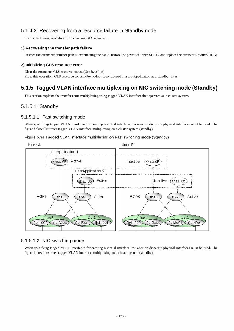
5.1.4.3 Recovering from a resource failure in Standby nodeSee the following procedure for recovering GLS resource.
1) Recovering the transfer path failure
Restore the erroneous transfer path (Reconnecting the cable, restore the power of Switch/HUB, and replace the erroneous Switch/HUB)
2) Initializing GLS resource error
Clear the erroneous GLS resource status. (Use hvutil -c)From this operation, GLS resource for standby node is reconfigured in a userApplication as a standby status.
5.1.5 Tagged VLAN interface multiplexing on NIC switching mode (Standby)This section explains the transfer route multiplexing using tagged VLAN interface that operates on a cluster system.
5.1.5.1 Standby
5.1.5.1.1 Fast switching mode
When specifying tagged VLAN interfaces for creating a virtual interface, the ones on disparate physical interfaces must be used. Thefigure below illustrates tagged VLAN interface multiplexing on a cluster system (standby).
Figure 5.34 Tagged VLAN interface multiplexing on Fast switching mode (Standby)
5.1.5.1.2 NIC switching mode
When specifying tagged VLAN interfaces for creating a virtual interface, the ones on disparate physical interfaces must be used. Thefigure below illustrates tagged VLAN interface multiplexing on a cluster system (standby).
- 176 -
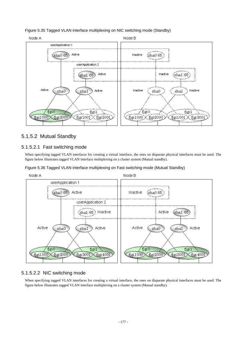
Figure 5.35 Tagged VLAN interface multiplexing on NIC switching mode (Standby)
5.1.5.2 Mutual Standby
5.1.5.2.1 Fast switching mode
When specifying tagged VLAN interfaces for creating a virtual interface, the ones on disparate physical interfaces must be used. Thefigure below illustrates tagged VLAN interface multiplexing on a cluster system (Mutual standby).
Figure 5.36 Tagged VLAN interface multiplexing on Fast switching mode (Mutual Standby)
5.1.5.2.2 NIC switching mode
When specifying tagged VLAN interfaces for creating a virtual interface, the ones on disparate physical interfaces must be used. Thefigure below illustrates tagged VLAN interface multiplexing on a cluster system (Mutual standby).
- 177 -
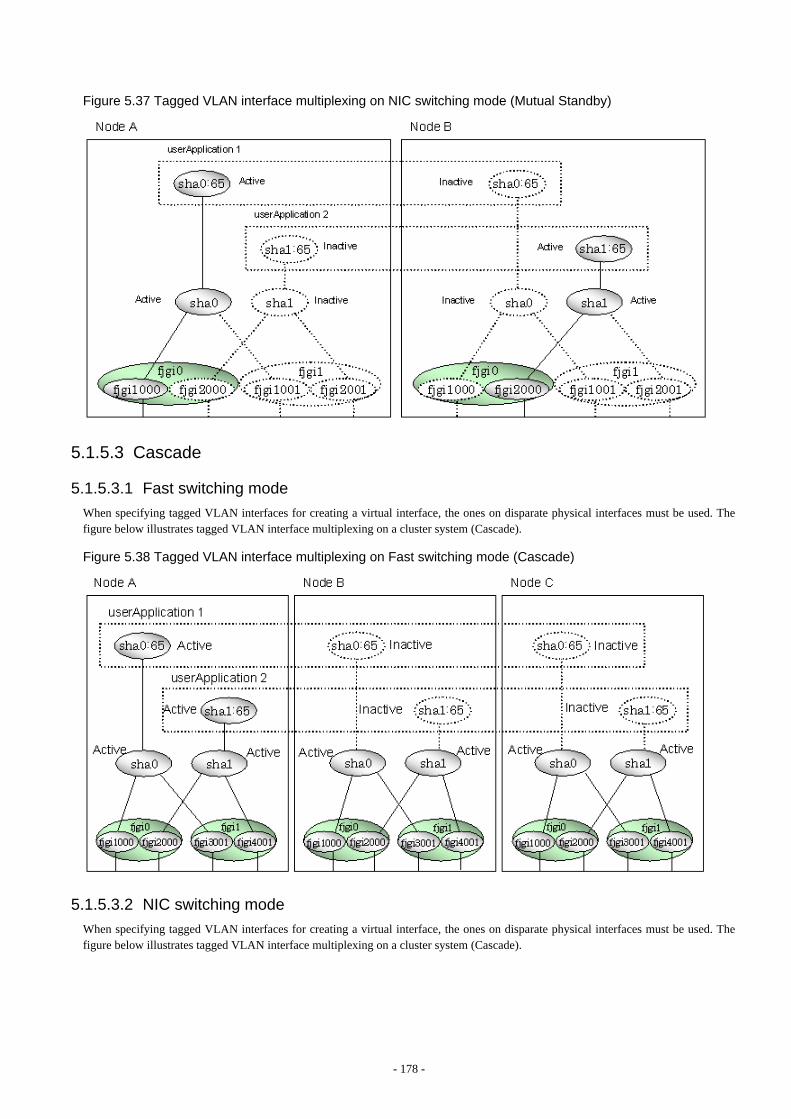
Figure 5.37 Tagged VLAN interface multiplexing on NIC switching mode (Mutual Standby)
5.1.5.3 Cascade
5.1.5.3.1 Fast switching mode
When specifying tagged VLAN interfaces for creating a virtual interface, the ones on disparate physical interfaces must be used. Thefigure below illustrates tagged VLAN interface multiplexing on a cluster system (Cascade).
Figure 5.38 Tagged VLAN interface multiplexing on Fast switching mode (Cascade)
5.1.5.3.2 NIC switching mode
When specifying tagged VLAN interfaces for creating a virtual interface, the ones on disparate physical interfaces must be used. Thefigure below illustrates tagged VLAN interface multiplexing on a cluster system (Cascade).
- 178 -

Figure 5.39 Tagged VLAN interface multiplexing on NIC switching mode (Cascade)
5.2 Adding configuration for Cluster SystemIn addition to configuring standard environment, configuration of takeover virtual interface and cluster environment is required for thecluster system.
Figure 5.40 Flowchart for adding configuration for cluster system shows a flow chart of configuring additional cluster environment for1:1 Standby Operation. For mutual standby and N:1 operation standby, follow the steps from "1) Set the configuration information" to "5)Setup the cluster environment" for the number of necessary node. Refer to "Appendix B Examples of configuring system environments".
- 179 -
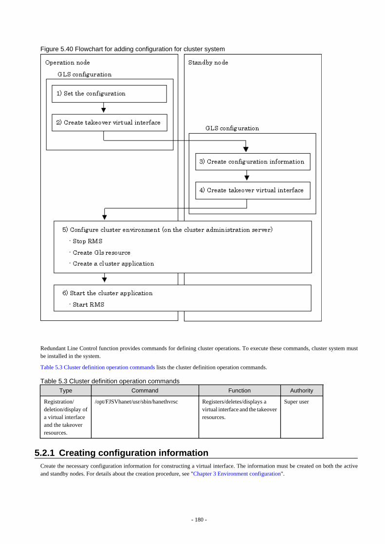
Figure 5.40 Flowchart for adding configuration for cluster system
Redundant Line Control function provides commands for defining cluster operations. To execute these commands, cluster system mustbe installed in the system.
Table 5.3 Cluster definition operation commands lists the cluster definition operation commands.
Table 5.3 Cluster definition operation commands
Type Command Function Authority
Registration/deletion/display ofa virtual interfaceand the takeoverresources.
/opt/FJSVhanet/usr/sbin/hanethvrsc Registers/deletes/displays avirtual interface and the takeoverresources.
Super user
5.2.1 Creating configuration informationCreate the necessary configuration information for constructing a virtual interface. The information must be created on both the activeand standby nodes. For details about the creation procedure, see "Chapter 3 Environment configuration".
- 180 -
5.2.2 Creating Takeover virtual interfaceTakeover virtual interface for registering with userApplication is set up. It is necessary to perform this setup on all nodes. When settingfor Fast switching mode, it is necessary to set a "takeover IP address". (Not necessary to set for NIC switching mode.) An example of thesetting is as follows. See "7.14 hanethvrsc Command" for the detail of the command.
Note
If IPv6 address is used for the takeover virtual interface in Fast switching mode or NIC switching mode, it may take approximately 30seconds to resume the connection after switching the node. However, by preliminary starting IPv6 routing daemon, the connection can beresumed immediately after switching the node. For details, refer to "F.2 Troubleshooting".
[Configuring a takeover virtual interface]
# /opt/FJSVhanet/usr/sbin/hanethvrsc create -n "virtual-interface-name" [-i takeover-IP-address]
5.2.3 Configuring cluster systemRegister the takeover virtual interface created in "5.2.2 Creating Takeover virtual interface" as Gls resource, and create a userApplication.Cluster system can be configured using RMS Wizard. Refer to "PRIMECLUSTER Installation and Administration Guide" for details.
5.2.4 Starting a userApplicationAfter completing the configuration for a cluster system, start the userApplication.Refer to "PRIMECLUSTER Installation and Administration Guide" for details.
5.3 Modifying configuration for Cluster SystemConfiguration information and takeover resource information operated by the cluster system cannot be changed directly. Delete thetakeover resource information first, and after changing corresponding configuration information, register the takeover resourcesinformation again.
5.4 Deleting configuration for Cluster SystemFor deleting the configuration of a cluster system, follow the figure below. For mutual standby operation, follow the steps from "2) Deletetakeover virtual interface" up to "5) Delete configuration information" for the number of necessary nodes.
Note
Before deleting cluster configuration settings, it is recommended to backup the configuration settings of the cluster system. By preliminarybacking up the configuration settings, it is possible to restore the system in case system trouble occurs and unable to recover from it. Referto "5.5 Backup/Restore Cluster configuration settings" for details.
- 181 -
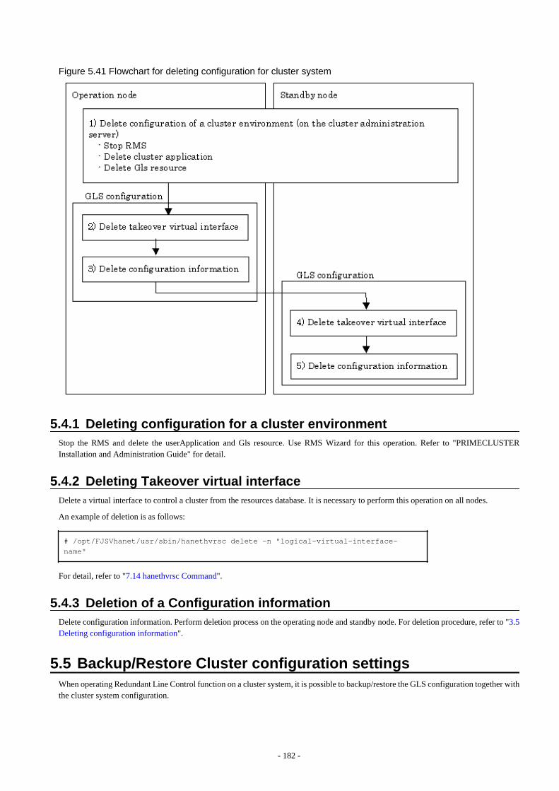
Figure 5.41 Flowchart for deleting configuration for cluster system
5.4.1 Deleting configuration for a cluster environmentStop the RMS and delete the userApplication and Gls resource. Use RMS Wizard for this operation. Refer to "PRIMECLUSTERInstallation and Administration Guide" for detail.
5.4.2 Deleting Takeover virtual interfaceDelete a virtual interface to control a cluster from the resources database. It is necessary to perform this operation on all nodes.
An example of deletion is as follows:
# /opt/FJSVhanet/usr/sbin/hanethvrsc delete -n "logical-virtual-interface-name"
For detail, refer to "7.14 hanethvrsc Command".
5.4.3 Deletion of a Configuration informationDelete configuration information. Perform deletion process on the operating node and standby node. For deletion procedure, refer to "3.5Deleting configuration information".
5.5 Backup/Restore Cluster configuration settingsWhen operating Redundant Line Control function on a cluster system, it is possible to backup/restore the GLS configuration together withthe cluster system configuration.
- 182 -

Redundant Line Control function is compliant with backing up/restoring the configuration settings of a cluster system. Executing thefollowing commands enables backup/restore configuration settings of both cluster system and Redundant Line Control function.
Backup:# /opt/SMAW/SMAWccbr/bin/cfbackup <Return>Restore:# /opt/SMAW/SMAWccbr/bin/cfrestore <Return>
See
For details on backing up and restoring the cluster system, refer to "Chapter 11 Backing Up and Restoring a PRIMECLUSTER System"on "PRIMECLUSTER Installation and Administration Guide".
- 183 -
Chapter 6 MaintenanceThis chapter focuses on a general approach to troubleshooting. It presents a troubleshooting strategy and identifies commands that areavailable in Resource Coordinator for finding and correcting problems. Further, it discusses how to collect troubleshooting information.
6.1 Redundant Line Control function Troubleshooting Data to beCollected
In the event of a problem in Redundant Line Control function operation, Redundant Line Control function troubleshooting requiresfollowing information about the problem to be collected.When collecting examination materials of a Redundant Line Control function all together, see "6.1.1 Command to collect materials".
1) Collecting materials common to each mode
Collect the following materials for examination when an error occurred in the workings of a Redundant Line Control function:
- The content of the detailed operation and error messages when a phenomenon occurred.
- A console log (/var/adm/messages) file
- A log file (/var/opt/FJSVhanet/log/*) of a Redundant Line Control function
- An environment setting file (/etc/opt/FJSVhanet/config/*) of a Redundant Line Control function
- The result of executing /opt/FJSVnet/usr/sbin/dsphanet
- The result of executing ifconfig -a
- The result of executing netstat -ni
- The result of executing netstat -nr
- The result of executing netstat -np
- Packet trace (For details on collecting packet traces, see "6.2 Packet Trace".)
2) When an error occurred in Fast switching mode
When an error occurred in Fast switching mode, perform "1)Collecting materials common to each mode" and collect the followingmaterials:
- The result of executing /opt/FJSVhanet/usr/sbin/dsphanet -o
3) When an error occurred in NIC switching mode
When an error occurred in NIC switching mode, perform "1) Collecting materials common to each mode" and collect the followingmaterials:
- The result of executing ps -ef
- Debug information of the HUB monitoring function (See "6.1.2 Collecting debug information/Output command" as to how to set,etc.)
4) When an error occurred in GS/SURE linkage mode
When an error occurred in GS/SURE linkage mode, perform "1) Collecting materials common to each mode" and collect the followingmaterials:
- The result of executing /opt/FJSVhanet/usr/sbin/dsphanet -c
- The result of executing /opt/FJSVhanet/usr/sbin/dsppoll -c
- Debug information of the communication target monitoring function (See "6.1.2 Collecting debug information/Output command" asto how to set, etc.)
- 184 -
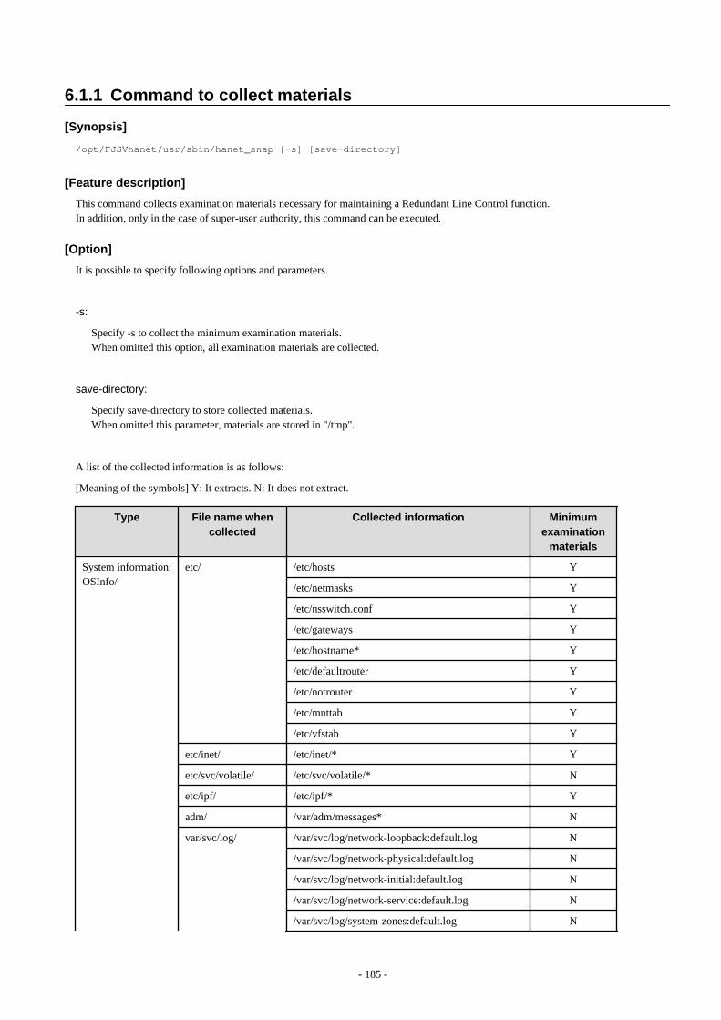
6.1.1 Command to collect materials
[Synopsis]
/opt/FJSVhanet/usr/sbin/hanet_snap [-s] [save-directory]
[Feature description]
This command collects examination materials necessary for maintaining a Redundant Line Control function.In addition, only in the case of super-user authority, this command can be executed.
[Option]
It is possible to specify following options and parameters.
-s:
Specify -s to collect the minimum examination materials.When omitted this option, all examination materials are collected.
save-directory:
Specify save-directory to store collected materials.When omitted this parameter, materials are stored in "/tmp".
A list of the collected information is as follows:
[Meaning of the symbols] Y: It extracts. N: It does not extract.
Type File name when
collectedCollected information Minimum
examinationmaterials
System information:OSInfo/
etc/ /etc/hosts Y
/etc/netmasks Y
/etc/nsswitch.conf Y
/etc/gateways Y
/etc/hostname* Y
/etc/defaultrouter Y
/etc/notrouter Y
/etc/mnttab Y
/etc/vfstab Y
etc/inet/ /etc/inet/* Y
etc/svc/volatile/ /etc/svc/volatile/* N
etc/ipf/ /etc/ipf/* Y
adm/ /var/adm/messages* N
var/svc/log/ /var/svc/log/network-loopback:default.log N
/var/svc/log/network-physical:default.log N
/var/svc/log/network-initial:default.log N
/var/svc/log/network-service:default.log N
/var/svc/log/system-zones:default.log N
- 185 -
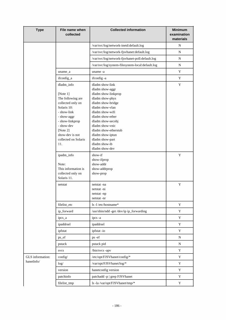
Type File name whencollected
Collected information Minimumexamination
materials
/var/svc/log/network-inetd:default.log N
/var/svc/log/network-fjsvhanet:default.log N
/var/svc/log/network-fjsvhanet-poll:default.log N
/var/svc/log/system-filesystem-local:default.log N
uname_a uname -a Y
ifconfig_a ifconfig -a Y
dladm_info
[Note 1]The following arecollected only onSolaris 10:- show-link- show-aggr- show-linkprop- show-dev[Note 2]show-dev is notcollected on Solaris11.
dladm show-linkdladm show-aggrdladm show-linkpropdladm show-physdladm show-bridgedladm show-vlandladm show-wifidladm show-etherdladm show-secobjdladm show-vnicdladm show-etherstubdladm show-iptundladm show-partdladm show-ibdladm show-dev
Y
ipadm_info
Note:This information iscollected only onSolaris 11.
show-ifshow-ifpropshow-addrshow-addrpropshow-prop
Y
netstat netstat -nanetstat -ninetstat -npnetstat -nr
Y
filelist_etc ls -l /etc/hostname* Y
ip_forward /usr/sbin/ndd -get /dev/ip ip_forwarding Y
ipcs_a ipcs -a Y
ipaddrsel ipaddrsel Y
ipfstat ipfstat -io Y
ps_ef ps -ef N
pstack pstack pid N
svcs /bin/svcs -apv Y
GLS information:hanetInfo/
config/ /etc/opt/FJSVhanet/config/* Y
log/ /var/opt/FJSVhanet/log/* Y
version hanetconfig version Y
patchinfo patchadd -p | grep FJSVhanet Y
filelist_tmp ls -la /var/opt/FJSVhanet/tmp/* Y
- 186 -
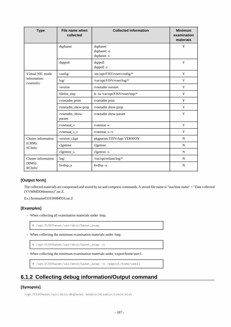
Type File name whencollected
Collected information Minimumexamination
materials
dsphanet dsphanetdsphanet -odsphanet -c
Y
dsppoll dsppolldsppoll -c
Y
Virtual NIC modeinformation:rvnetinfo/
config/ /etc/opt/FJSVrvnet/config/* Y
log/ /var/opt/FJSVrvnet/log/* Y
version rvnetadm version Y
filelist_tmp ls -la /var/opt/FJSVrvnet/tmp/* Y
rvnetadm_print rvnetadm print Y
rvnetadm_show-prop rvnetadm show-prop Y
rvnetadm_show-param
rvnetadm show-param Y
rvnetstat_v rvnetstat -v Y
rvnetstat_s_v rvnetstat -s -v Y
Cluster information(CRM):SCInfo/
version_clapi pkgparam FJSVclapi VERSION N
clgettree clgettree N
clgettree_s clgettree -s N
Cluster information(RMS):RCInfo/
log/ /var/opt/reliant/log/* N
hvdisp_a hvdisp -a N
[Output form]
The collected materials are compressed and stored by tar and compress commands. A stored file name is "machine name" + "Date collected(YYMMDDhhmmss)".tar.Z.
Ex.) hostname031030084916.tar.Z
[Examples]
- When collecting all examination materials under /tmp.
# /opt/FJSVhanet/usr/sbin/hanet_snap
- When collecting the minimum examination materials under /tmp.
# /opt/FJSVhanet/usr/sbin/hanet_snap -s
- When collecting the minimum examination materials under /export/home/user1.
# /opt/FJSVhanet/usr/sbin/hanet_snap -s /export/home/user1
6.1.2 Collecting debug information/Output command
[Synopsis]
/opt/FJSVhanet/usr/sbin/dbghanet enable|disable|trace|stat
- 187 -

[Feature description]
Specifies whether the debug information for the HUB monitoring function is collected and outputs the log information. The following arethe debug information to be collected:
- Execution log of the ping command
If a line failure is detected due to no response from the ping monitoring, execute the ping command to collect the result and packetssent and received. These logs are useful for determining the point where an error occurred or identifying the cause of the failure whena network failure occurs. The execution logs of the ping command are collected only when collecting the debug information is enabled.
- Statistical information of the ping command
Statistical information of the execution time of the ping command for the monitoring target is logged periodically. The maximumvalue, the minimum value, the average value, and the distribution of the execution time of the ping command are logged in the statisticalinformation. These logs are useful for determining the load condition of the system. Statistical information is collected regardless ofwhether collecting the debug information is enabled or not.This information is output to the log information of the Redundant Line Control function, and also included in the information collectedby the "hanet_snap" command.
[Options]
It is possible to specify following options and parameters.
enable
Enables collecting the debug information. When enabled collecting the debug information, the execution logs of the ping commandare collected.
disable
Disables collecting the debug information of the HUB monitoring function.
trace
Outputs the log information of the Redundant Line Control function where the execution logs of the ping command are recorded.
stat
Outputs the log information of the Redundant Line Control function where the statistical information of the ping command is recorded.
[Notes]
When collecting the debug information is enabled, it takes about three to five seconds longer to switch NICs or clusters for collecting logs,comparing to the case when collecting the debug information is not enabled. Switching will be continued regardless of whether the pingcommand, which is executed to collect logs, fails or not.
[Examples]
- To enable collecting the execution logs of the ping command
# /opt/FJSVhanet/usr/sbin/dbghanet enable
- To disable collecting the execution logs of the ping command
# /opt/FJSVhanet/usr/sbin/dbghanet disable
- To output the execution logs of the ping command
- 188 -

# /opt/FJSVhanet/usr/sbin/dbghanet trace
- To output the statistical information of the ping command
# /opt/FJSVhanet/usr/sbin/dbghanet stat
6.2 Packet TraceThis section describes how to collect packet traces of Redundant Line Control function.
6.2.1 Collecting packet tracesIf you want to collect packet traces of virtual interfaces, follow the example below.
1. Execute hanetconfig print to check the physical interfaces bundled with the virtual interface which you want to obtain.
[IPv4,Patrol]
Name Hostname Mode MAC Adder/Phys ip Interface List+-----------+---------------+----+-----------------+-------------------+ sha0 hostA t hme0,hme1 sha1 10.0.1.1 r hme0,hme1 sha12 - p 02:00:00:00:00:01 sha11 sha2 hostC d fjgi1000,fjgi1001 sha3 - p 02:00:00:00:00:10 sha2 sha4 192.168.10.50 n fjgi4 sha5 192.168.20.50 n fjgi5 sha6 192.168.100.50 c sha4,sha5
[IPv6]
Name Hostname/prefix Mode Interface List+-----------+---------------------------------+----+-------------------+ sha10 - t qfe0,qfe1 sha10:2 hostB/64 sha11 fec0:1::123/64 d qfe2,qfe3
2. Execute the snoop command to collect packet traces.
If a virtual interface bundles several physical interfaces, execute the snoop(1M) command for all physical interfaces in the bundle.
Execution examples are shown below:
- sha0 and sha1
# snoop -d hme0 -o /tmp/packet_trace.hme0# snoop -d hme1 -o /tmp/packet_trace.hme1
- sha2 and sha3
# snoop -d fjgi1000 -o /tmp/packet_trace.fjgi1000# snoop -d fjgi1001 -o /tmp/packet_trace.fjgi1001
- sha10 and sha10:2
# snoop -d qfe0 -o /tmp/packet_trace.qfe0# snoop -d qfe1 -o /tmp/packet_trace.qfe1
- sha11 and sha12
- 189 -
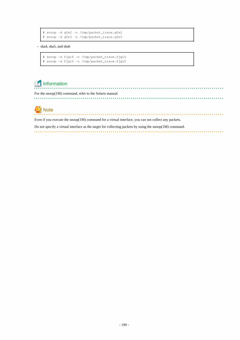
# snoop -d qfe2 -o /tmp/packet_trace.qfe2# snoop -d qfe3 -o /tmp/packet_trace.qfe3
- sha4, sha5, and sha6
# snoop -d fjgi4 -o /tmp/packet_trace.fjgi4# snoop -d fjgi5 -o /tmp/packet_trace.fjgi5
Information
For the snoop(1M) command, refer to the Solaris manual.
Note
Even if you execute the snoop(1M) command for a virtual interface, you can not collect any packets.
Do not specify a virtual interface as the target for collecting packets by using the snoop(1M) command.
- 190 -
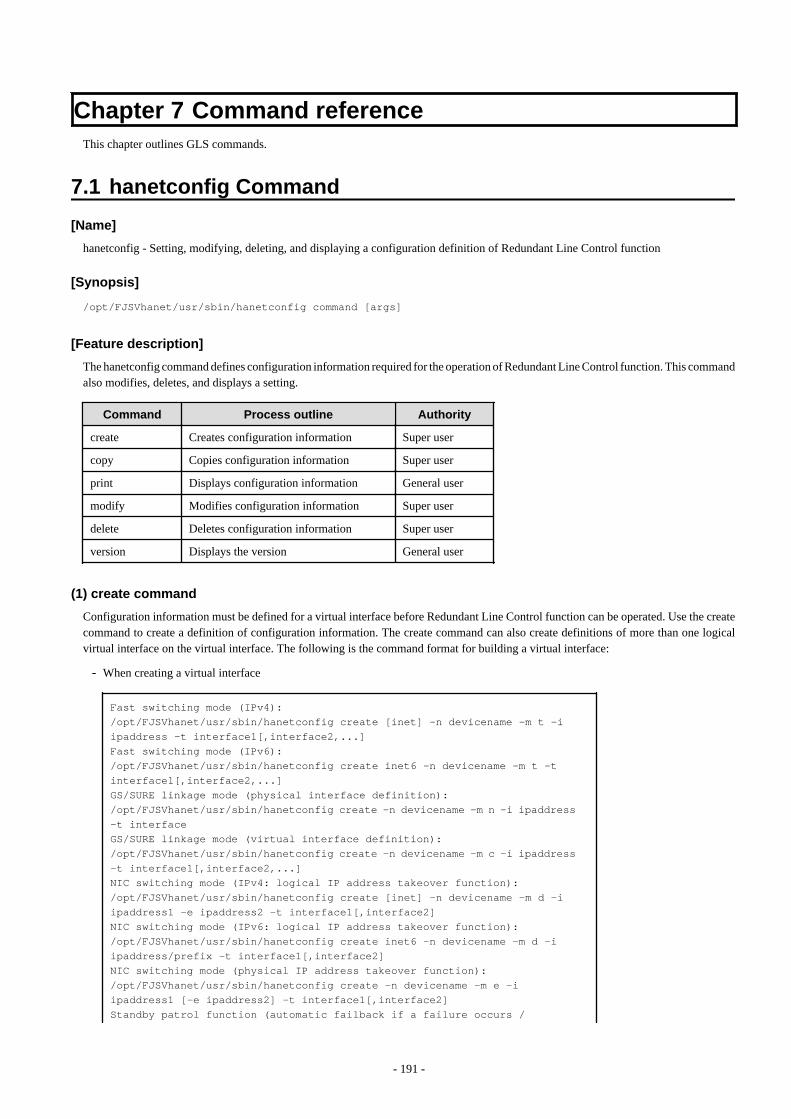
Chapter 7 Command referenceThis chapter outlines GLS commands.
7.1 hanetconfig Command
[Name]
hanetconfig - Setting, modifying, deleting, and displaying a configuration definition of Redundant Line Control function
[Synopsis]
/opt/FJSVhanet/usr/sbin/hanetconfig command [args]
[Feature description]
The hanetconfig command defines configuration information required for the operation of Redundant Line Control function. This commandalso modifies, deletes, and displays a setting.
Command Process outline Authority
create Creates configuration information Super user
copy Copies configuration information Super user
print Displays configuration information General user
modify Modifies configuration information Super user
delete Deletes configuration information Super user
version Displays the version General user
(1) create command
Configuration information must be defined for a virtual interface before Redundant Line Control function can be operated. Use the createcommand to create a definition of configuration information. The create command can also create definitions of more than one logicalvirtual interface on the virtual interface. The following is the command format for building a virtual interface:
- When creating a virtual interface
Fast switching mode (IPv4):/opt/FJSVhanet/usr/sbin/hanetconfig create [inet] -n devicename -m t -i ipaddress -t interface1[,interface2,...]Fast switching mode (IPv6):/opt/FJSVhanet/usr/sbin/hanetconfig create inet6 -n devicename -m t -t interface1[,interface2,...]GS/SURE linkage mode (physical interface definition):/opt/FJSVhanet/usr/sbin/hanetconfig create -n devicename -m n -i ipaddress -t interfaceGS/SURE linkage mode (virtual interface definition):/opt/FJSVhanet/usr/sbin/hanetconfig create -n devicename -m c -i ipaddress -t interface1[,interface2,...]NIC switching mode (IPv4: logical IP address takeover function):/opt/FJSVhanet/usr/sbin/hanetconfig create [inet] -n devicename -m d -i ipaddress1 -e ipaddress2 -t interface1[,interface2]NIC switching mode (IPv6: logical IP address takeover function):/opt/FJSVhanet/usr/sbin/hanetconfig create inet6 -n devicename -m d -i ipaddress/prefix -t interface1[,interface2]NIC switching mode (physical IP address takeover function):/opt/FJSVhanet/usr/sbin/hanetconfig create -n devicename -m e -i ipaddress1 [-e ipaddress2] -t interface1[,interface2]Standby patrol function (automatic failback if a failure occurs /
- 191 -

immediate automatic failback):/opt/FJSVhanet/usr/sbin/hanetconfig create -n devicename -m {p | q} [-a MAC_address] -t interface
- When creating a logical virtual interface
Fast switching mode (IPv4):/opt/FJSVhanet/usr/sbin/hanetconfig create [inet] -n devicename -i ipaddressFast switching mode (IPv6):/opt/FJSVhanet/usr/sbin/hanetconfig create inet6 -n devicename -i ipaddress/prefix
[inet | inet6]
Specify an IP address form to set to a virtual interface.
inet inet6
: IPv4 address: IPv6 address
When omitted, it is dealt with as specified inet. It is necessary to specify this option first (immediately after a string of "create") beforeother options.This option can be specified only when using Fast switching mode or NIC switching mode (a logical IP address takeover function).
-n devicename:
Specify the name of a virtual interface or logical virtual interface for which the configuration information should be set. Specify thevirtual interface name with a string "sha" and is followed by a value (0 to 255) (such as sha0 and sha10). Specify the logical virtualinterface name as "virtual-interface-name: value (2 to 64)" (such as sha0:2 and sha10:5). If you specify a virtual interface or logicalvirtual interface in any other format, an error message is output and this command terminates abnormally. In addition, Logical virtualinterface can only be configured on operation mode "t".
-m t|n|c|d|e|p|q:
Specify an operation mode. If devicename is a logical virtual interface, specify the operation mode of a corresponding virtual interface.
t: Fast switching mode
Specify this parameter to use the Redundant Line Control function in Fast switching mode.
n: GS/SURE linkage mode (physical interface definition)
Specify this parameter to use the Redundant Line Control function in GS/SURE linkage mode. A physical interface used to actuallyperform communication is created.
c: GS/SURE linkage mode (virtual interface definition)
Specify this parameter to use the Redundant Line Control function in GS/SURE linkage mode. A virtual interface that bundlesphysical interfaces defined in operation mode n to perform communication is created.
d: NIC switching mode (logical IP address takeover function)
Specify this parameter to use the Redundant Line Control function in NIC switching mode. This mode activates logical interfaceand physical interface.
e: NIC switching mode (physical IP address takeover function)
Specify this parameter to use the Redundant Line Control function in NIC switching mode. This mode activates only physicalinterface.
- 192 -
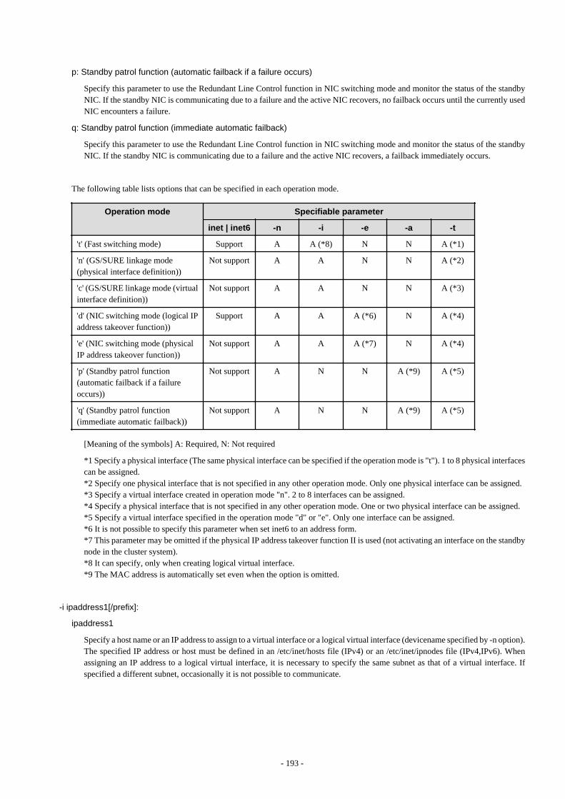
p: Standby patrol function (automatic failback if a failure occurs)
Specify this parameter to use the Redundant Line Control function in NIC switching mode and monitor the status of the standbyNIC. If the standby NIC is communicating due to a failure and the active NIC recovers, no failback occurs until the currently usedNIC encounters a failure.
q: Standby patrol function (immediate automatic failback)
Specify this parameter to use the Redundant Line Control function in NIC switching mode and monitor the status of the standbyNIC. If the standby NIC is communicating due to a failure and the active NIC recovers, a failback immediately occurs.
The following table lists options that can be specified in each operation mode.
Operation mode Specifiable parameter
inet | inet6 -n -i -e -a -t
't' (Fast switching mode) Support A A (*8) N N A (*1)
'n' (GS/SURE linkage mode(physical interface definition))
Not support A A N N A (*2)
'c' (GS/SURE linkage mode (virtualinterface definition))
Not support A A N N A (*3)
'd' (NIC switching mode (logical IPaddress takeover function))
Support A A A (*6) N A (*4)
'e' (NIC switching mode (physicalIP address takeover function))
Not support A A A (*7) N A (*4)
'p' (Standby patrol function(automatic failback if a failureoccurs))
Not support A N N A (*9) A (*5)
'q' (Standby patrol function(immediate automatic failback))
Not support A N N A (*9) A (*5)
[Meaning of the symbols] A: Required, N: Not required
*1 Specify a physical interface (The same physical interface can be specified if the operation mode is "t"). 1 to 8 physical interfacescan be assigned.*2 Specify one physical interface that is not specified in any other operation mode. Only one physical interface can be assigned.*3 Specify a virtual interface created in operation mode "n". 2 to 8 interfaces can be assigned.*4 Specify a physical interface that is not specified in any other operation mode. One or two physical interface can be assigned.*5 Specify a virtual interface specified in the operation mode "d" or "e". Only one interface can be assigned.*6 It is not possible to specify this parameter when set inet6 to an address form.*7 This parameter may be omitted if the physical IP address takeover function II is used (not activating an interface on the standbynode in the cluster system).*8 It can specify, only when creating logical virtual interface.*9 The MAC address is automatically set even when the option is omitted.
-i ipaddress1[/prefix]:
ipaddress1
Specify a host name or an IP address to assign to a virtual interface or a logical virtual interface (devicename specified by -n option).The specified IP address or host must be defined in an /etc/inet/hosts file (IPv4) or an /etc/inet/ipnodes file (IPv4,IPv6). Whenassigning an IP address to a logical virtual interface, it is necessary to specify the same subnet as that of a virtual interface. Ifspecified a different subnet, occasionally it is not possible to communicate.
- 193 -

[/prefix]
Specify the length of a prefix of ipaddress1 following "/" (slash). The range possible to specify is between zero to 128. This parameteris required only when specifying an IPv6 address to ipaddress1 or a host name defined in an /etc/inet/ipnodes file. It is not possibleto specify for an IPv4 address.
-e ipaddress2:
Specify an IP address or a host name to assign to a physical interface. It is possible to set an IP address or a host name in an IPv4 formonly and must be defined in an /etc/inet/hosts and /etc/inet/ipnodes files. It is possible to specify this option only when specified inetfor an address form. (When specified inet6, a link local address is automatically assigned.) It is necessary to set this option in NICswitching mode (operation mode is "d" or "e"). In cluster operation, it is possible to omit this option if an interface of NIC switchingmode (operation mode is "e") is not activated by a standby node.
-t interface1[,interface2,...]:
Specify interface names to be bundled by a virtual interface, by listing them delimited with a comma (,).Specify virtual interface names (such as sha1 and sha2) for GS/SURE linkage mode (operation mode "c") or standby patrol function(operation mode "p" or "q").To configure other than GS/SURE linkage mode (operation mode "c") or standby patrol function (operation mode "p" or "q"), specifythe name of physical interface (such as eri0 or hme0) or the name of tagged VLAN interface (such as ce1000 or fjgi1000).
-a MAC_address:
Specify a MAC address to be allocated to the standby NIC as XX:XX:XX:XX:XX:XX (X represents a hexadecimal from 0 to F).In the environment where the MAC addresses of the active NIC and the standby NIC are the same, specify the local MAC address(02:XX:XX:XX:XX:XX : "02" in the beginning indicates that this is a local MAC address). In the environment where the MACaddresses of the active NIC and the standby NIC are not the same, specify 0:0:0:0:0:0 so that the global address set to the NIC is to beused as it is.If this option is not specified, the local MAC address based on the global address is automatically set in the environment where theMAC addresses of the active NIC and the standby NIC are the same, and 0:0:0:0:0:0 is automatically set in the environment wherethe MAC addresses of the active NIC and the standby NIC are not the same.
Note
- Do not use the MAC address of a node connected on the same LAN. No normal operation is guaranteed if duplicate addresses areused.
- When multiplexing the virtual networks (vsw and vnet) in Oracle VM environments, specify 0:0:0:0:0:0 to the MAC address becausethe virtual MAC address generated by the operating system must be used as it is.
- You cannot use the -a option in the following cases:
- When setting the standby patrol for a virtual interface bundling tagged VLAN interfaces with Solaris 11
- When setting the standby patrol for a virtual interface in a non-global zone with the exclusive-IP configuration
(2) copy command
Use the copy command to create different configuration information while sharing an NIC used in other configuration information (virtualinterface in NIC switching mode (operation mode "d")). This command thus allows configuration information to be automatically createdby using the copy source information and without requiring you to specify an IP address to be attached to a physical interface, interfacenames to be bundled by a virtual interface, and an operation mode. This command realizes simpler operation than directly executing thehanetconfig create command.In addition, this command can copy only virtual interface of NIC switching mode (operation mode "d").
The following is the command format for copying a virtual interface:
- When duplicating a virtual interface of IPv4 from a virtual interface of IPv4
- 194 -
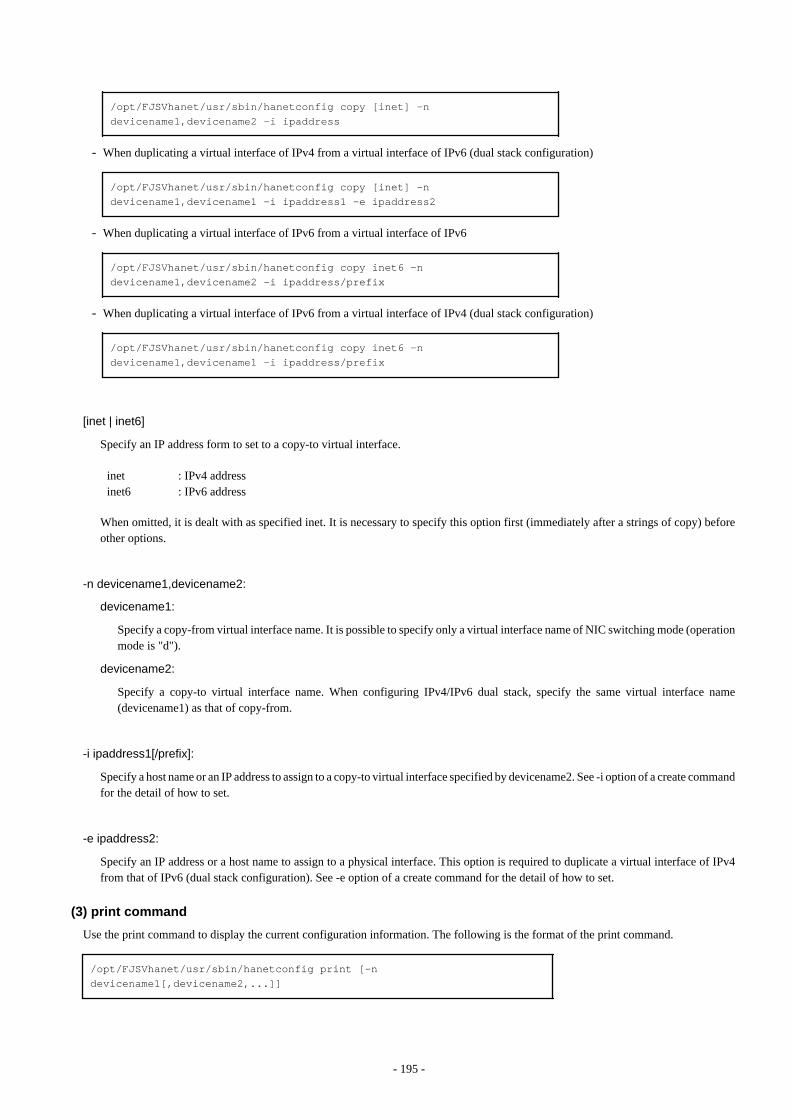
/opt/FJSVhanet/usr/sbin/hanetconfig copy [inet] -n devicename1,devicename2 -i ipaddress
- When duplicating a virtual interface of IPv4 from a virtual interface of IPv6 (dual stack configuration)
/opt/FJSVhanet/usr/sbin/hanetconfig copy [inet] -n devicename1,devicename1 -i ipaddress1 -e ipaddress2
- When duplicating a virtual interface of IPv6 from a virtual interface of IPv6
/opt/FJSVhanet/usr/sbin/hanetconfig copy inet6 -n devicename1,devicename2 -i ipaddress/prefix
- When duplicating a virtual interface of IPv6 from a virtual interface of IPv4 (dual stack configuration)
/opt/FJSVhanet/usr/sbin/hanetconfig copy inet6 -n devicename1,devicename1 -i ipaddress/prefix
[inet | inet6]
Specify an IP address form to set to a copy-to virtual interface.
inet inet6
: IPv4 address: IPv6 address
When omitted, it is dealt with as specified inet. It is necessary to specify this option first (immediately after a strings of copy) beforeother options.
-n devicename1,devicename2:
devicename1:
Specify a copy-from virtual interface name. It is possible to specify only a virtual interface name of NIC switching mode (operationmode is "d").
devicename2:
Specify a copy-to virtual interface name. When configuring IPv4/IPv6 dual stack, specify the same virtual interface name(devicename1) as that of copy-from.
-i ipaddress1[/prefix]:
Specify a host name or an IP address to assign to a copy-to virtual interface specified by devicename2. See -i option of a create commandfor the detail of how to set.
-e ipaddress2:
Specify an IP address or a host name to assign to a physical interface. This option is required to duplicate a virtual interface of IPv4from that of IPv6 (dual stack configuration). See -e option of a create command for the detail of how to set.
(3) print command
Use the print command to display the current configuration information. The following is the format of the print command.
/opt/FJSVhanet/usr/sbin/hanetconfig print [-n devicename1[,devicename2,...]]
- 195 -
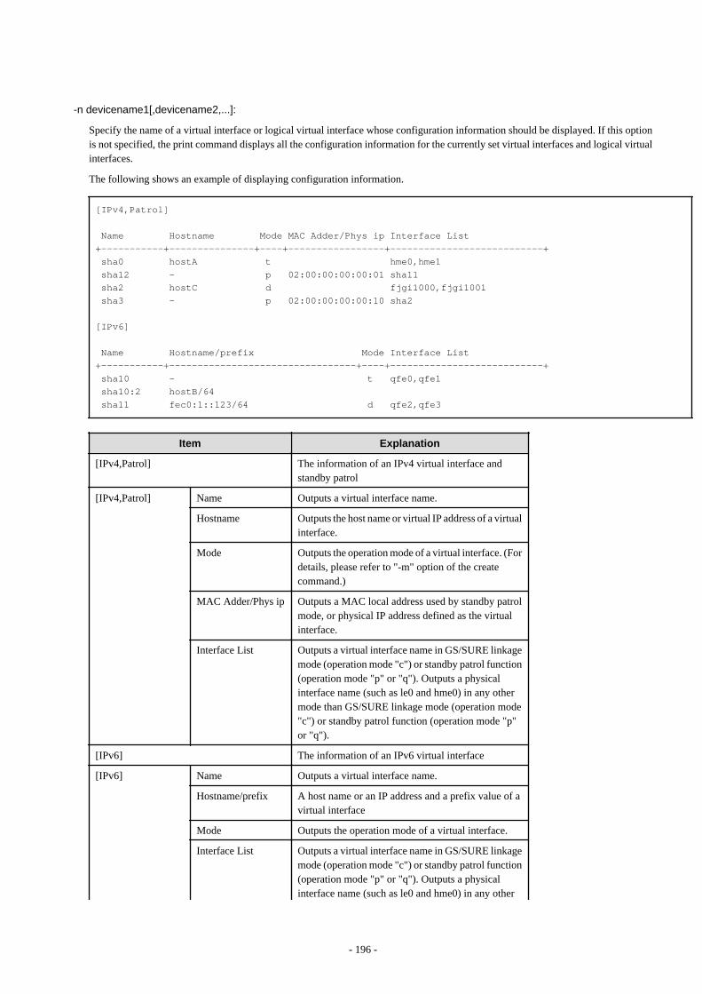
-n devicename1[,devicename2,...]:
Specify the name of a virtual interface or logical virtual interface whose configuration information should be displayed. If this optionis not specified, the print command displays all the configuration information for the currently set virtual interfaces and logical virtualinterfaces.
The following shows an example of displaying configuration information.
[IPv4,Patrol]
Name Hostname Mode MAC Adder/Phys ip Interface List+-----------+---------------+----+-----------------+---------------------------+ sha0 hostA t hme0,hme1 sha12 - p 02:00:00:00:00:01 sha11 sha2 hostC d fjgi1000,fjgi1001 sha3 - p 02:00:00:00:00:10 sha2
[IPv6]
Name Hostname/prefix Mode Interface List+-----------+---------------------------------+----+---------------------------+ sha10 - t qfe0,qfe1 sha10:2 hostB/64 sha11 fec0:1::123/64 d qfe2,qfe3
Item Explanation
[IPv4,Patrol] The information of an IPv4 virtual interface andstandby patrol
[IPv4,Patrol] Name Outputs a virtual interface name.
Hostname Outputs the host name or virtual IP address of a virtualinterface.
Mode Outputs the operation mode of a virtual interface. (Fordetails, please refer to "-m" option of the createcommand.)
MAC Adder/Phys ip Outputs a MAC local address used by standby patrolmode, or physical IP address defined as the virtualinterface.
Interface List Outputs a virtual interface name in GS/SURE linkagemode (operation mode "c") or standby patrol function(operation mode "p" or "q"). Outputs a physicalinterface name (such as le0 and hme0) in any othermode than GS/SURE linkage mode (operation mode"c") or standby patrol function (operation mode "p"or "q").
[IPv6] The information of an IPv6 virtual interface
[IPv6] Name Outputs a virtual interface name.
Hostname/prefix A host name or an IP address and a prefix value of avirtual interface
Mode Outputs the operation mode of a virtual interface.
Interface List Outputs a virtual interface name in GS/SURE linkagemode (operation mode "c") or standby patrol function(operation mode "p" or "q"). Outputs a physicalinterface name (such as le0 and hme0) in any other
- 196 -
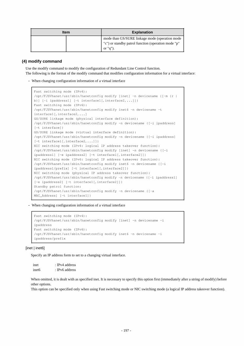
Item Explanation
mode than GS/SURE linkage mode (operation mode"c") or standby patrol function (operation mode "p"or "q").
(4) modify command
Use the modify command to modify the configuration of Redundant Line Control function.The following is the format of the modify command that modifies configuration information for a virtual interface:
- When changing configuration information of a virtual interface
Fast switching mode (IPv4):/opt/FJSVhanet/usr/sbin/hanetconfig modify [inet] -n devicename {[-m {r | b}] [-i ipaddress1] [-t interface1[,interface2,...]]}Fast switching mode (IPv6):/opt/FJSVhanet/usr/sbin/hanetconfig modify inet6 -n devicename -t interface1[,interface2,...]GS/SURE linkage mode (physical interface definition):/opt/FJSVhanet/usr/sbin/hanetconfig modify -n devicename {[-i ipaddress] [-t interface]}GS/SURE linkage mode (virtual interface definition):/opt/FJSVhanet/usr/sbin/hanetconfig modify -n devicename {[-i ipaddress] [-t interface1[,interface2,...]]}NIC switching mode (IPv4: logical IP address takeover function):/opt/FJSVhanet/usr/sbin/hanetconfig modify [inet] -n devicename {[-i ipaddress1] [-e ipaddress2] [-t interface1[,interface2]]}NIC switching mode (IPv6: logical IP address takeover function):/opt/FJSVhanet/usr/sbin/hanetconfig modify inet6 -n devicename {[-i ipaddress1/prefix] [-t interface1[,interface2]]}NIC switching mode (physical IP address takeover function):/opt/FJSVhanet/usr/sbin/hanetconfig modify -n devicename {[-i ipaddress1] [-e ipaddress2] [-t interface1[,interface2]]}Standby patrol function:/opt/FJSVhanet/usr/sbin/hanetconfig modify -n devicename {[-a MAC_Address] [-t interface1]}
- When changing configuration information of a virtual interface
Fast switching mode (IPv4):/opt/FJSVhanet/usr/sbin/hanetconfig modify [inet] -n devicename -i ipaddressFast switching mode (IPv6):/opt/FJSVhanet/usr/sbin/hanetconfig modify inet6 -n devicename -i ipaddress/prefix
[inet | inet6]
Specify an IP address form to set to a changing virtual interface.
inet inet6
: IPv4 address: IPv6 address
When omitted, it is dealt with as specified inet. It is necessary to specify this option first (immediately after a string of modify) beforeother options.This option can be specified only when using Fast switching mode or NIC switching mode (a logical IP address takeover function).
- 197 -
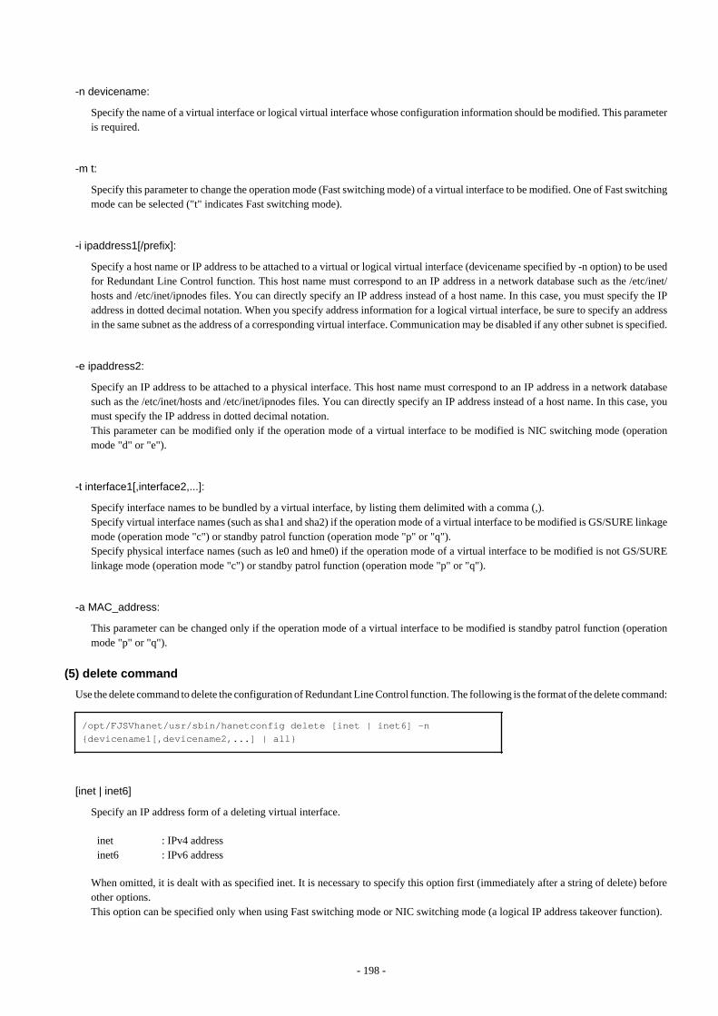
-n devicename:
Specify the name of a virtual interface or logical virtual interface whose configuration information should be modified. This parameteris required.
-m t:
Specify this parameter to change the operation mode (Fast switching mode) of a virtual interface to be modified. One of Fast switchingmode can be selected ("t" indicates Fast switching mode).
-i ipaddress1[/prefix]:
Specify a host name or IP address to be attached to a virtual or logical virtual interface (devicename specified by -n option) to be usedfor Redundant Line Control function. This host name must correspond to an IP address in a network database such as the /etc/inet/hosts and /etc/inet/ipnodes files. You can directly specify an IP address instead of a host name. In this case, you must specify the IPaddress in dotted decimal notation. When you specify address information for a logical virtual interface, be sure to specify an addressin the same subnet as the address of a corresponding virtual interface. Communication may be disabled if any other subnet is specified.
-e ipaddress2:
Specify an IP address to be attached to a physical interface. This host name must correspond to an IP address in a network databasesuch as the /etc/inet/hosts and /etc/inet/ipnodes files. You can directly specify an IP address instead of a host name. In this case, youmust specify the IP address in dotted decimal notation.This parameter can be modified only if the operation mode of a virtual interface to be modified is NIC switching mode (operationmode "d" or "e").
-t interface1[,interface2,...]:
Specify interface names to be bundled by a virtual interface, by listing them delimited with a comma (,).Specify virtual interface names (such as sha1 and sha2) if the operation mode of a virtual interface to be modified is GS/SURE linkagemode (operation mode "c") or standby patrol function (operation mode "p" or "q").Specify physical interface names (such as le0 and hme0) if the operation mode of a virtual interface to be modified is not GS/SURElinkage mode (operation mode "c") or standby patrol function (operation mode "p" or "q").
-a MAC_address:
This parameter can be changed only if the operation mode of a virtual interface to be modified is standby patrol function (operationmode "p" or "q").
(5) delete command
Use the delete command to delete the configuration of Redundant Line Control function. The following is the format of the delete command:
/opt/FJSVhanet/usr/sbin/hanetconfig delete [inet | inet6] -n {devicename1[,devicename2,...] | all}
[inet | inet6]
Specify an IP address form of a deleting virtual interface.
inet inet6
: IPv4 address: IPv6 address
When omitted, it is dealt with as specified inet. It is necessary to specify this option first (immediately after a string of delete) beforeother options.This option can be specified only when using Fast switching mode or NIC switching mode (a logical IP address takeover function).
- 198 -
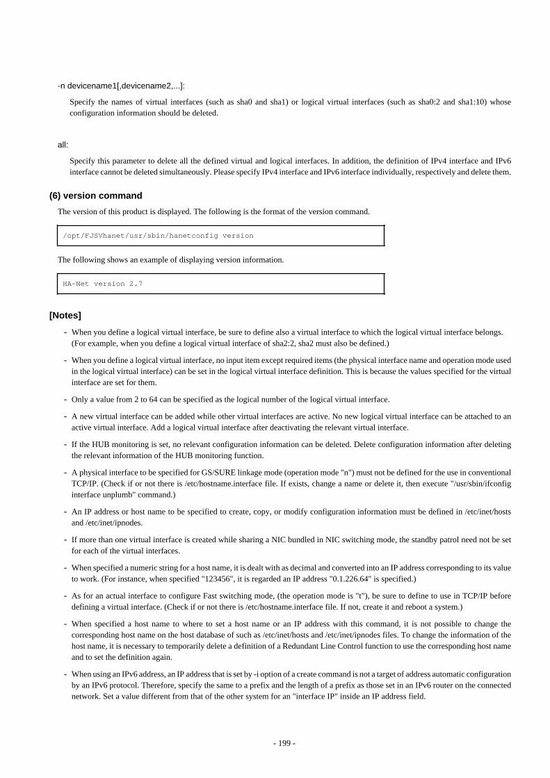
-n devicename1[,devicename2,...]:
Specify the names of virtual interfaces (such as sha0 and sha1) or logical virtual interfaces (such as sha0:2 and sha1:10) whoseconfiguration information should be deleted.
all:
Specify this parameter to delete all the defined virtual and logical interfaces. In addition, the definition of IPv4 interface and IPv6interface cannot be deleted simultaneously. Please specify IPv4 interface and IPv6 interface individually, respectively and delete them.
(6) version command
The version of this product is displayed. The following is the format of the version command.
/opt/FJSVhanet/usr/sbin/hanetconfig version
The following shows an example of displaying version information.
HA-Net version 2.7
[Notes]
- When you define a logical virtual interface, be sure to define also a virtual interface to which the logical virtual interface belongs.(For example, when you define a logical virtual interface of sha2:2, sha2 must also be defined.)
- When you define a logical virtual interface, no input item except required items (the physical interface name and operation mode usedin the logical virtual interface) can be set in the logical virtual interface definition. This is because the values specified for the virtualinterface are set for them.
- Only a value from 2 to 64 can be specified as the logical number of the logical virtual interface.
- A new virtual interface can be added while other virtual interfaces are active. No new logical virtual interface can be attached to anactive virtual interface. Add a logical virtual interface after deactivating the relevant virtual interface.
- If the HUB monitoring is set, no relevant configuration information can be deleted. Delete configuration information after deletingthe relevant information of the HUB monitoring function.
- A physical interface to be specified for GS/SURE linkage mode (operation mode "n") must not be defined for the use in conventionalTCP/IP. (Check if or not there is /etc/hostname.interface file. If exists, change a name or delete it, then execute "/usr/sbin/ifconfiginterface unplumb" command.)
- An IP address or host name to be specified to create, copy, or modify configuration information must be defined in /etc/inet/hostsand /etc/inet/ipnodes.
- If more than one virtual interface is created while sharing a NIC bundled in NIC switching mode, the standby patrol need not be setfor each of the virtual interfaces.
- When specified a numeric string for a host name, it is dealt with as decimal and converted into an IP address corresponding to its valueto work. (For instance, when specified "123456", it is regarded an IP address "0.1.226.64" is specified.)
- As for an actual interface to configure Fast switching mode, (the operation mode is "t"), be sure to define to use in TCP/IP beforedefining a virtual interface. (Check if or not there is /etc/hostname.interface file. If not, create it and reboot a system.)
- When specified a host name to where to set a host name or an IP address with this command, it is not possible to change thecorresponding host name on the host database of such as /etc/inet/hosts and /etc/inet/ipnodes files. To change the information of thehost name, it is necessary to temporarily delete a definition of a Redundant Line Control function to use the corresponding host nameand to set the definition again.
- When using an IPv6 address, an IP address that is set by -i option of a create command is not a target of address automatic configurationby an IPv6 protocol. Therefore, specify the same to a prefix and the length of a prefix as those set in an IPv6 router on the connectednetwork. Set a value different from that of the other system for an "interface IP" inside an IP address field.
- 199 -
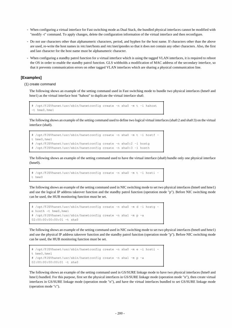
- When configuring a virtual interface for Fast switching mode as Dual Stack, the bundled physical interfaces cannot be modified with"modify -t" command. To apply changes, delete the configuration information of the virtual interface and then reconfigure.
- Do not use characters other than alphanumeric characters, period, and hyphen for the host name. If characters other than the aboveare used, re-write the host names in /etc/inet/hosts and /etc/inet/ipnodes so that it does not contain any other characters. Also, the firstand last character for the host name must be alphanumeric character.
- When configuring a standby patrol function for a virtual interface which is using the tagged VLAN interfaces, it is required to rebootthe OS in order to enable the standby patrol function. GLS withholds a modification of MAC address of the secondary interface, sothat it prevents communication errors on other tagged VLAN interfaces which are sharing a physical communication line.
[Examples]
(1) create command
The following shows an example of the setting command used in Fast switching mode to bundle two physical interfaces (hme0 andhme1) as the virtual interface host "hahost" to duplicate the virtual interface sha0.
# /opt/FJSVhanet/usr/sbin/hanetconfig create -n sha0 -m t -i hahost -t hme0,hme1
The following shows an example of the setting command used to define two logical virtual interfaces (sha0:2 and sha0:3) on the virtualinterface (sha0).
# /opt/FJSVhanet/usr/sbin/hanetconfig create -n sha0 -m t -i hostf -t hme0,hme1# /opt/FJSVhanet/usr/sbin/hanetconfig create -n sha0:2 -i hostg# /opt/FJSVhanet/usr/sbin/hanetconfig create -n sha0:3 -i hosth
The following shows an example of the setting command used to have the virtual interface (sha0) bundle only one physical interface(hme0).
# /opt/FJSVhanet/usr/sbin/hanetconfig create -n sha0 -m t -i hosti -t hme0
The following shows an example of the setting command used in NIC switching mode to set two physical interfaces (hme0 and hme1)and use the logical IP address takeover function and the standby patrol function (operation mode "p"). Before NIC switching modecan be used, the HUB monitoring function must be set.
# /opt/FJSVhanet/usr/sbin/hanetconfig create -n sha0 -m d -i hostg -e hosth -t hme0,hme1# /opt/FJSVhanet/usr/sbin/hanetconfig create -n sha1 -m p -a 02:00:00:00:00:01 -t sha0
The following shows an example of the setting command used in NIC switching mode to set two physical interfaces (hme0 and hme1)and use the physical IP address takeover function and the standby patrol function (operation mode "p"). Before NIC switching modecan be used, the HUB monitoring function must be set.
# /opt/FJSVhanet/usr/sbin/hanetconfig create -n sha0 -m e -i hosti -t hme0,hme1# /opt/FJSVhanet/usr/sbin/hanetconfig create -n sha1 -m p -a 02:00:00:00:00:01 -t sha0
The following shows an example of the setting command used in GS/SURE linkage mode to have two physical interfaces (hme0 andhme1) bundled. For this purpose, first set the physical interfaces in GS/SURE linkage mode (operation mode "n"), then create virtualinterfaces in GS/SURE linkage mode (operation mode "n"), and have the virtual interfaces bundled to set GS/SURE linkage mode(operation mode "c").
- 200 -
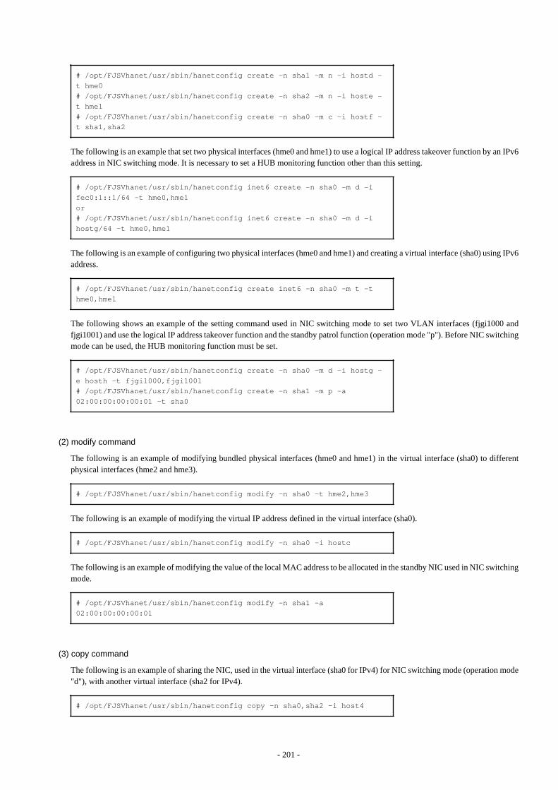
# /opt/FJSVhanet/usr/sbin/hanetconfig create -n sha1 -m n -i hostd -t hme0# /opt/FJSVhanet/usr/sbin/hanetconfig create -n sha2 -m n -i hoste -t hme1# /opt/FJSVhanet/usr/sbin/hanetconfig create -n sha0 -m c -i hostf -t sha1,sha2
The following is an example that set two physical interfaces (hme0 and hme1) to use a logical IP address takeover function by an IPv6address in NIC switching mode. It is necessary to set a HUB monitoring function other than this setting.
# /opt/FJSVhanet/usr/sbin/hanetconfig inet6 create -n sha0 -m d -i fec0:1::1/64 -t hme0,hme1or# /opt/FJSVhanet/usr/sbin/hanetconfig inet6 create -n sha0 -m d -i hostg/64 -t hme0,hme1
The following is an example of configuring two physical interfaces (hme0 and hme1) and creating a virtual interface (sha0) using IPv6address.
# /opt/FJSVhanet/usr/sbin/hanetconfig create inet6 -n sha0 -m t -t hme0,hme1
The following shows an example of the setting command used in NIC switching mode to set two VLAN interfaces (fjgi1000 andfjgi1001) and use the logical IP address takeover function and the standby patrol function (operation mode "p"). Before NIC switchingmode can be used, the HUB monitoring function must be set.
# /opt/FJSVhanet/usr/sbin/hanetconfig create -n sha0 -m d -i hostg -e hosth -t fjgi1000,fjgi1001# /opt/FJSVhanet/usr/sbin/hanetconfig create -n sha1 -m p -a 02:00:00:00:00:01 -t sha0
(2) modify command
The following is an example of modifying bundled physical interfaces (hme0 and hme1) in the virtual interface (sha0) to differentphysical interfaces (hme2 and hme3).
# /opt/FJSVhanet/usr/sbin/hanetconfig modify -n sha0 -t hme2,hme3
The following is an example of modifying the virtual IP address defined in the virtual interface (sha0).
# /opt/FJSVhanet/usr/sbin/hanetconfig modify -n sha0 -i hostc
The following is an example of modifying the value of the local MAC address to be allocated in the standby NIC used in NIC switchingmode.
# /opt/FJSVhanet/usr/sbin/hanetconfig modify -n sha1 -a 02:00:00:00:00:01
(3) copy command
The following is an example of sharing the NIC, used in the virtual interface (sha0 for IPv4) for NIC switching mode (operation mode"d"), with another virtual interface (sha2 for IPv4).
# /opt/FJSVhanet/usr/sbin/hanetconfig copy -n sha0,sha2 -i host4
- 201 -
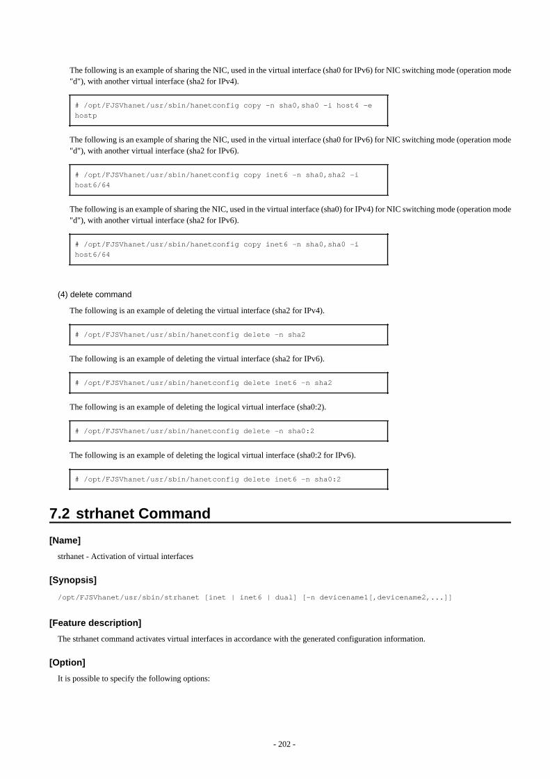
The following is an example of sharing the NIC, used in the virtual interface (sha0 for IPv6) for NIC switching mode (operation mode"d"), with another virtual interface (sha2 for IPv4).
# /opt/FJSVhanet/usr/sbin/hanetconfig copy -n sha0,sha0 -i host4 -e hostp
The following is an example of sharing the NIC, used in the virtual interface (sha0 for IPv6) for NIC switching mode (operation mode"d"), with another virtual interface (sha2 for IPv6).
# /opt/FJSVhanet/usr/sbin/hanetconfig copy inet6 -n sha0,sha2 -i host6/64
The following is an example of sharing the NIC, used in the virtual interface (sha0) for IPv4) for NIC switching mode (operation mode"d"), with another virtual interface (sha2 for IPv6).
# /opt/FJSVhanet/usr/sbin/hanetconfig copy inet6 -n sha0,sha0 -i host6/64
(4) delete command
The following is an example of deleting the virtual interface (sha2 for IPv4).
# /opt/FJSVhanet/usr/sbin/hanetconfig delete -n sha2
The following is an example of deleting the virtual interface (sha2 for IPv6).
# /opt/FJSVhanet/usr/sbin/hanetconfig delete inet6 -n sha2
The following is an example of deleting the logical virtual interface (sha0:2).
# /opt/FJSVhanet/usr/sbin/hanetconfig delete -n sha0:2
The following is an example of deleting the logical virtual interface (sha0:2 for IPv6).
# /opt/FJSVhanet/usr/sbin/hanetconfig delete inet6 -n sha0:2
7.2 strhanet Command
[Name]
strhanet - Activation of virtual interfaces
[Synopsis]
/opt/FJSVhanet/usr/sbin/strhanet [inet | inet6 | dual] [-n devicename1[,devicename2,...]]
[Feature description]
The strhanet command activates virtual interfaces in accordance with the generated configuration information.
[Option]
It is possible to specify the following options:
- 202 -
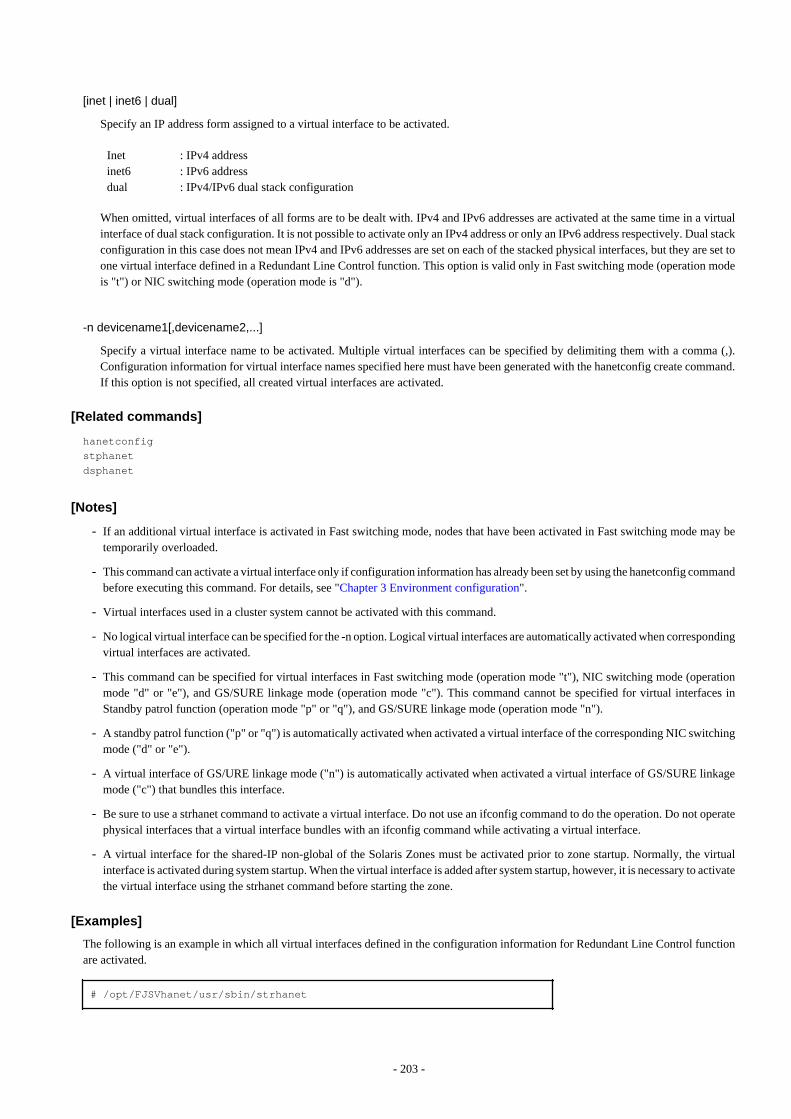
[inet | inet6 | dual]
Specify an IP address form assigned to a virtual interface to be activated.
Inet inet6dual
: IPv4 address: IPv6 address: IPv4/IPv6 dual stack configuration
When omitted, virtual interfaces of all forms are to be dealt with. IPv4 and IPv6 addresses are activated at the same time in a virtualinterface of dual stack configuration. It is not possible to activate only an IPv4 address or only an IPv6 address respectively. Dual stackconfiguration in this case does not mean IPv4 and IPv6 addresses are set on each of the stacked physical interfaces, but they are set toone virtual interface defined in a Redundant Line Control function. This option is valid only in Fast switching mode (operation modeis "t") or NIC switching mode (operation mode is "d").
-n devicename1[,devicename2,...]
Specify a virtual interface name to be activated. Multiple virtual interfaces can be specified by delimiting them with a comma (,).Configuration information for virtual interface names specified here must have been generated with the hanetconfig create command.If this option is not specified, all created virtual interfaces are activated.
[Related commands]
hanetconfigstphanetdsphanet
[Notes]
- If an additional virtual interface is activated in Fast switching mode, nodes that have been activated in Fast switching mode may betemporarily overloaded.
- This command can activate a virtual interface only if configuration information has already been set by using the hanetconfig commandbefore executing this command. For details, see "Chapter 3 Environment configuration".
- Virtual interfaces used in a cluster system cannot be activated with this command.
- No logical virtual interface can be specified for the -n option. Logical virtual interfaces are automatically activated when correspondingvirtual interfaces are activated.
- This command can be specified for virtual interfaces in Fast switching mode (operation mode "t"), NIC switching mode (operationmode "d" or "e"), and GS/SURE linkage mode (operation mode "c"). This command cannot be specified for virtual interfaces inStandby patrol function (operation mode "p" or "q"), and GS/SURE linkage mode (operation mode "n").
- A standby patrol function ("p" or "q") is automatically activated when activated a virtual interface of the corresponding NIC switchingmode ("d" or "e").
- A virtual interface of GS/URE linkage mode ("n") is automatically activated when activated a virtual interface of GS/SURE linkagemode ("c") that bundles this interface.
- Be sure to use a strhanet command to activate a virtual interface. Do not use an ifconfig command to do the operation. Do not operatephysical interfaces that a virtual interface bundles with an ifconfig command while activating a virtual interface.
- A virtual interface for the shared-IP non-global of the Solaris Zones must be activated prior to zone startup. Normally, the virtualinterface is activated during system startup. When the virtual interface is added after system startup, however, it is necessary to activatethe virtual interface using the strhanet command before starting the zone.
[Examples]
The following is an example in which all virtual interfaces defined in the configuration information for Redundant Line Control functionare activated.
# /opt/FJSVhanet/usr/sbin/strhanet
- 203 -
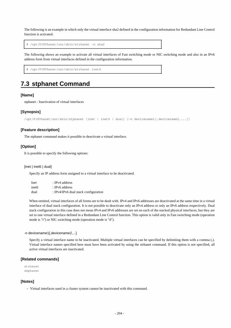
The following is an example in which only the virtual interface sha2 defined in the configuration information for Redundant Line Controlfunction is activated.
# /opt/FJSVhanet/usr/sbin/strhanet -n sha2
The following shows an example to activate all virtual interfaces of Fast switching mode or NIC switching mode and also in an IPv6address form from virtual interfaces defined in the configuration information.
# /opt/FJSVhanet/usr/sbin/strhanet inet6
7.3 stphanet Command
[Name]
stphanet - Inactivation of virtual interfaces
[Synopsis]
/opt/FJSVhanet/usr/sbin/stphanet [inet | inet6 | dual] [-n devicename1[,devicename2,...]]
[Feature description]
The stphanet command makes it possible to deactivate a virtual interface.
[Option]
It is possible to specify the following options:
[inet | inet6 | dual]
Specify an IP address form assigned to a virtual interface to be deactivated.
Inet inet6dual
: IPv4 address: IPv6 address: IPv4/IPv6 dual stack configuration
When omitted, virtual interfaces of all forms are to be dealt with. IPv4 and IPv6 addresses are deactivated at the same time in a virtualinterface of dual stack configuration. It is not possible to deactivate only an IPv4 address or only an IPv6 address respectively. Dualstack configuration in this case does not mean IPv4 and IPv6 addresses are set on each of the stacked physical interfaces, but they areset to one virtual interface defined in a Redundant Line Control function. This option is valid only in Fast switching mode (operationmode is "t") or NIC switching mode (operation mode is "d").
-n devicename1[,devicename2,...]
Specify a virtual interface name to be inactivated. Multiple virtual interfaces can be specified by delimiting them with a comma (,).Virtual interface names specified here must have been activated by using the strhanet command. If this option is not specified, allactive virtual interfaces are inactivated.
[Related commands]
strhanetdsphanet
[Notes]
- Virtual interfaces used in a cluster system cannot be inactivated with this command.
- 204 -
- Only logical virtual interfaces cannot be inactivated. By terminating virtual interfaces, related logical virtual interfaces areautomatically terminated.
- When inactivating virtual interfaces and logical virtual interfaces, a high-level application must be terminated first.
- It is possible to specify this command to a virtual interface of Fast switching mode (operation mode is "t"), NIC switching mode ("d"or "e"), and GS/SURE linkage mode ("c"). It is not possible to specify to a virtual interface of a standby patrol function ("p" or "q")and GS/SURE linkage mode ("n"). A Standby patrol function ("p" or "q") is automatically deactivated when deactivated a virtualinterface of the corresponding NIC switching mode ("d" or "e"). A virtual interface of GS/SURE linkage mode ("n") is automaticallydeactivated when deactivated a virtual interface of GS/SURE linkage mode ("c") that bundles this virtual interface.
- Be sure to use a stphanet command to deactivate a virtual interface. Do not use an ifconfig command to do the operation.
- A virtual interface of standby patrol set after activated NIC switching mode and activated by strptl command is not deactivated. Usestpptl command to deactivate.
- When a virtual interface of NIC switching mode is deactivated and only a virtual interface of standby patrol is activated, use stpptlcommand to deactivate the virtual interface of standby patrol.
- If the shared-IP non-global of the Solaris Zones is using the virtual interface, you cannot deactivate it. First, stop the Solaris Zonesthen deactivate the virtual interface by executing the stphanet command.
- For execution of this command for a virtual interface of NIC switching mode, if physical interfaces bundled by a virtual interface arenot used in any other virtual interfaces, physical IP is also deactivated in addition to virtual IP.
[Examples]
The following is an example in which all virtual interfaces (excluding virtual interfaces in cluster operation) defined in the configurationinformation for Redundant Line Control function are inactivated.
# /opt/FJSVhanet/usr/sbin/stphanet
The following is an example in which only the virtual interface sha2 defined in the configuration information for Redundant Line Controlfunction is inactivated.
# /opt/FJSVhanet/usr/sbin/stphanet -n sha2
The following shows an example to inactivate all virtual interfaces of Fast switching mode or NIC switching mode and also in dual stackconfiguration.
# /opt/FJSVhanet/usr/sbin/stphanet dual
7.4 dsphanet Command
[Name]
dsphanet - Displaying the operation status of virtual interfaces
[Synopsis]
/opt/FJSVhanet/usr/sbin/dsphanet [-n devicename1[,devicename2,...] | -o | -c]
[Feature description]
The dsphanet command displays the current operation status of virtual interfaces and logical virtual interfaces.
[Option]
You can specify the following options:
- 205 -
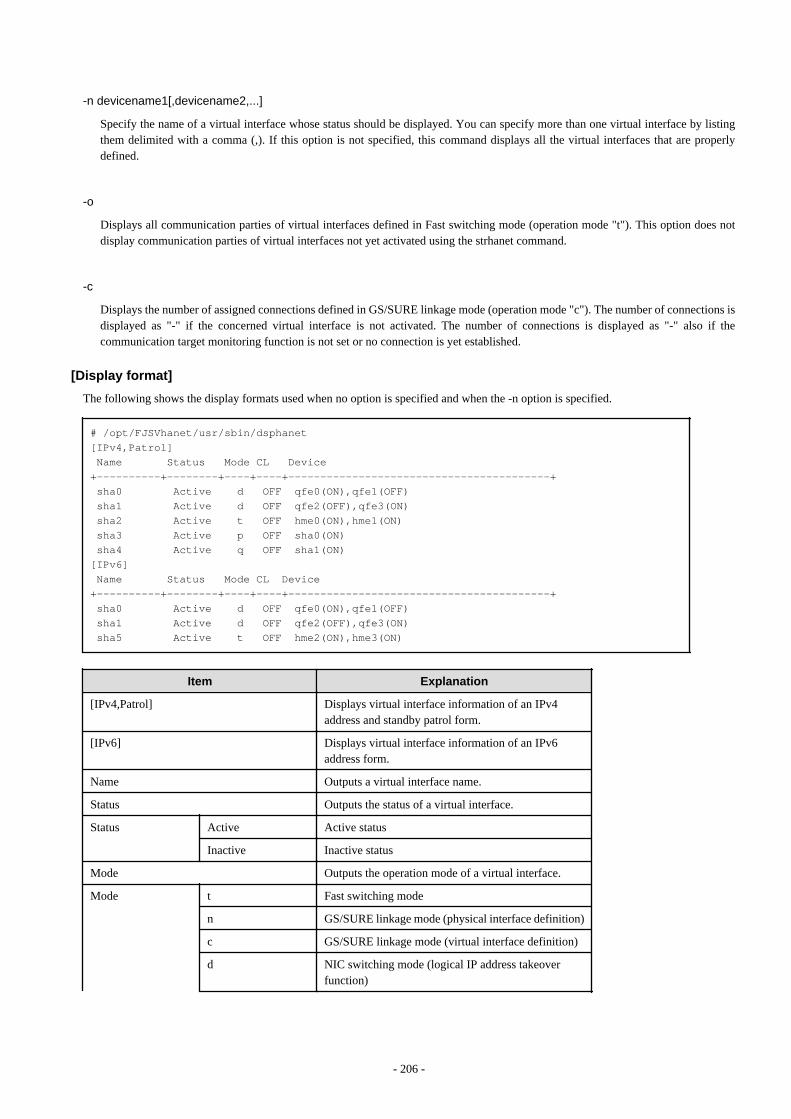
-n devicename1[,devicename2,...]
Specify the name of a virtual interface whose status should be displayed. You can specify more than one virtual interface by listingthem delimited with a comma (,). If this option is not specified, this command displays all the virtual interfaces that are properlydefined.
-o
Displays all communication parties of virtual interfaces defined in Fast switching mode (operation mode "t"). This option does notdisplay communication parties of virtual interfaces not yet activated using the strhanet command.
-c
Displays the number of assigned connections defined in GS/SURE linkage mode (operation mode "c"). The number of connections isdisplayed as "-" if the concerned virtual interface is not activated. The number of connections is displayed as "-" also if thecommunication target monitoring function is not set or no connection is yet established.
[Display format]
The following shows the display formats used when no option is specified and when the -n option is specified.
# /opt/FJSVhanet/usr/sbin/dsphanet[IPv4,Patrol] Name Status Mode CL Device +----------+--------+----+----+-----------------------------------------+ sha0 Active d OFF qfe0(ON),qfe1(OFF) sha1 Active d OFF qfe2(OFF),qfe3(ON) sha2 Active t OFF hme0(ON),hme1(ON) sha3 Active p OFF sha0(ON) sha4 Active q OFF sha1(ON)[IPv6] Name Status Mode CL Device+----------+--------+----+----+-----------------------------------------+ sha0 Active d OFF qfe0(ON),qfe1(OFF) sha1 Active d OFF qfe2(OFF),qfe3(ON) sha5 Active t OFF hme2(ON),hme3(ON)
Item Explanation
[IPv4,Patrol] Displays virtual interface information of an IPv4address and standby patrol form.
[IPv6] Displays virtual interface information of an IPv6address form.
Name Outputs a virtual interface name.
Status Outputs the status of a virtual interface.
Status Active Active status
Inactive Inactive status
Mode Outputs the operation mode of a virtual interface.
Mode t Fast switching mode
n GS/SURE linkage mode (physical interface definition)
c GS/SURE linkage mode (virtual interface definition)
d NIC switching mode (logical IP address takeoverfunction)
- 206 -
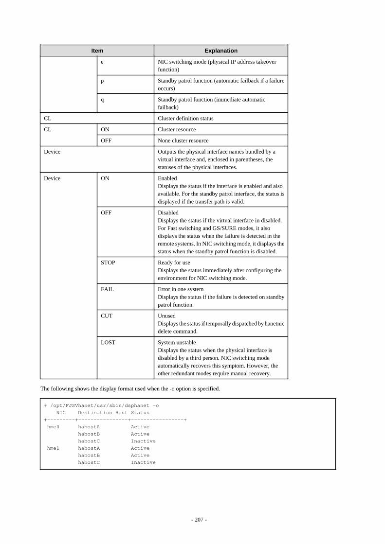
Item Explanation
e NIC switching mode (physical IP address takeoverfunction)
p Standby patrol function (automatic failback if a failureoccurs)
q Standby patrol function (immediate automaticfailback)
CL Cluster definition status
CL ON Cluster resource
OFF None cluster resource
Device Outputs the physical interface names bundled by avirtual interface and, enclosed in parentheses, thestatuses of the physical interfaces.
Device ON EnabledDisplays the status if the interface is enabled and alsoavailable. For the standby patrol interface, the status isdisplayed if the transfer path is valid.
OFF DisabledDisplays the status if the virtual interface in disabled.For Fast switching and GS/SURE modes, it alsodisplays the status when the failure is detected in theremote systems. In NIC switching mode, it displays thestatus when the standby patrol function is disabled.
STOP Ready for useDisplays the status immediately after configuring theenvironment for NIC switching mode.
FAIL Error in one systemDisplays the status if the failure is detected on standbypatrol function.
CUT UnusedDisplays the status if temporally dispatched by hanetnicdelete command.
LOST System unstableDisplays the status when the physical interface isdisabled by a third person. NIC switching modeautomatically recovers this symptom. However, theother redundant modes require manual recovery.
The following shows the display format used when the -o option is specified.
# /opt/FJSVhanet/usr/sbin/dsphanet -o NIC Destination Host Status+---------+----------------+-----------------+ hme0 hahostA Active hahostB Active hahostC Inactive hme1 hahostA Active hahostB Active hahostC Inactive
- 207 -
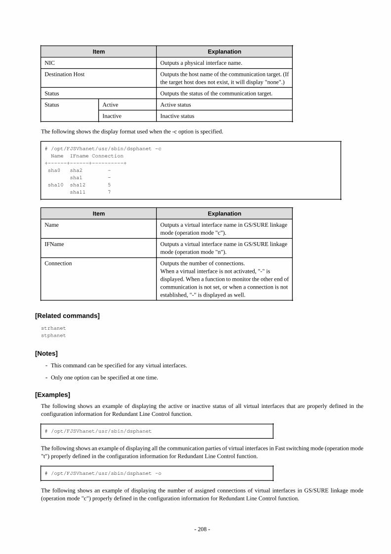
Item Explanation
NIC Outputs a physical interface name.
Destination Host Outputs the host name of the communication target. (Ifthe target host does not exist, it will display "none".)
Status Outputs the status of the communication target.
Status Active Active status
Inactive Inactive status
The following shows the display format used when the -c option is specified.
# /opt/FJSVhanet/usr/sbin/dsphanet -c Name IFname Connection+------+------+----------+ sha0 sha2 - sha1 - sha10 sha12 5 sha11 7
Item Explanation
Name Outputs a virtual interface name in GS/SURE linkagemode (operation mode "c").
IFName Outputs a virtual interface name in GS/SURE linkagemode (operation mode "n").
Connection Outputs the number of connections.When a virtual interface is not activated, "-" isdisplayed. When a function to monitor the other end ofcommunication is not set, or when a connection is notestablished, "-" is displayed as well.
[Related commands]
strhanetstphanet
[Notes]
- This command can be specified for any virtual interfaces.
- Only one option can be specified at one time.
[Examples]
The following shows an example of displaying the active or inactive status of all virtual interfaces that are properly defined in theconfiguration information for Redundant Line Control function.
# /opt/FJSVhanet/usr/sbin/dsphanet
The following shows an example of displaying all the communication parties of virtual interfaces in Fast switching mode (operation mode"t") properly defined in the configuration information for Redundant Line Control function.
# /opt/FJSVhanet/usr/sbin/dsphanet -o
The following shows an example of displaying the number of assigned connections of virtual interfaces in GS/SURE linkage mode(operation mode "c") properly defined in the configuration information for Redundant Line Control function.
- 208 -
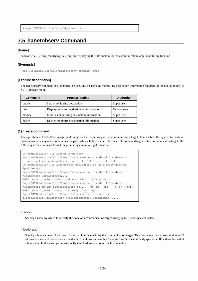
# /opt/FJSVhanet/usr/sbin/dsphanet -c
7.5 hanetobserv Command
[Name]
hanetobserv - Setting, modifying, deleting, and displaying the information for the communication target monitoring function
[Synopsis]
/opt/FJSVhanet/usr/sbin/hanetobserv command [args]
[Feature description]
The hanetobserv command sets, modifies, deletes, and displays the monitoring destination information required for the operation in GS/SURE linkage mode.
Command Process outline Authority
create Sets a monitoring destination Super user
print Displays monitoring destination information General user
modify Modifies monitoring destination information Super user
delete Deletes monitoring destination information Super user
(1) create command
The operation in GS/SURE linkage mode requires the monitoring of the communication target. This enables the system to continuecommunication using other communication paths when a failure occurs. Use the create command to generate a communication target. Thefollowing is the command format for generating a monitoring destination:
GS communication (If adding ipaddress):/opt/FJSVhanet/usr/sbin/hanetobserv create -n node -i ipaddress -t nicaddress1[,nicaddress2,...] -m {on | off} [-r {on | off}]GS communication (If adding more nicaddress to an already defined ipaddress):/opt/FJSVhanet/usr/sbin/hanetobserv create -n node -i ipaddress -t nicaddress3[,nicaddress4,...]SURE communication (using SURE communication function):/opt/FJSVhanet/usr/sbin/hanetobserv create -n node -i ipaddress -t nicaddress1:pm-id[,nicaddress2:pm-id,...] -m {on | off} [-r {on | off}]SURE communication (using TCP relay function):/opt/FJSVhanet/usr/sbin/hanetobserv create -i ipaddress -c clientaddress1[:subnetmask][,clientaddress2[:subnetmask],...]
-n node:
Specify a name by which to identify the node of a communication target, using up to 16 one-byte characters.
-i ipaddress:
Specify a host name or IP address of a virtual interface held by the communication target. This host name must correspond to an IPaddress in a network database such as the /etc/inet/hosts and /etc/inet/ipnodes files. You can directly specify an IP address instead ofa host name. In this case, you must specify the IP address in dotted decimal notation.
- 209 -
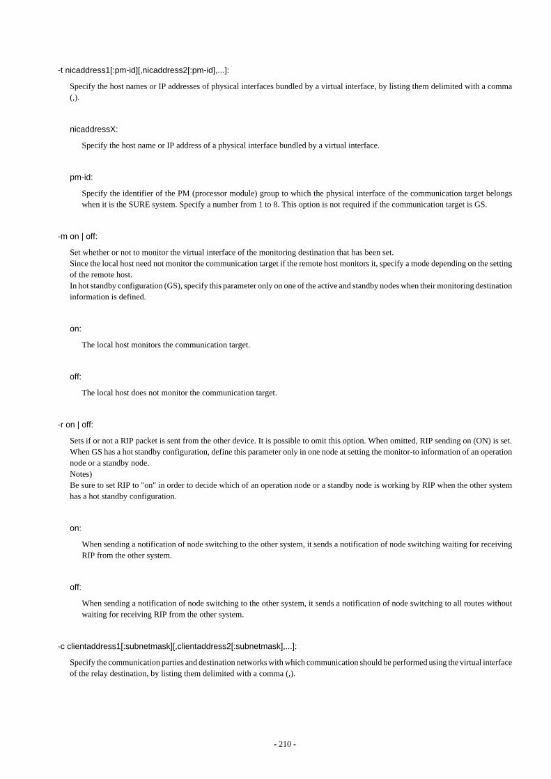
-t nicaddress1[:pm-id][,nicaddress2[:pm-id],...]:
Specify the host names or IP addresses of physical interfaces bundled by a virtual interface, by listing them delimited with a comma(,).
nicaddressX:
Specify the host name or IP address of a physical interface bundled by a virtual interface.
pm-id:
Specify the identifier of the PM (processor module) group to which the physical interface of the communication target belongswhen it is the SURE system. Specify a number from 1 to 8. This option is not required if the communication target is GS.
-m on | off:
Set whether or not to monitor the virtual interface of the monitoring destination that has been set.Since the local host need not monitor the communication target if the remote host monitors it, specify a mode depending on the settingof the remote host.In hot standby configuration (GS), specify this parameter only on one of the active and standby nodes when their monitoring destinationinformation is defined.
on:
The local host monitors the communication target.
off:
The local host does not monitor the communication target.
-r on | off:
Sets if or not a RIP packet is sent from the other device. It is possible to omit this option. When omitted, RIP sending on (ON) is set.When GS has a hot standby configuration, define this parameter only in one node at setting the monitor-to information of an operationnode or a standby node.Notes)Be sure to set RIP to "on" in order to decide which of an operation node or a standby node is working by RIP when the other systemhas a hot standby configuration.
on:
When sending a notification of node switching to the other system, it sends a notification of node switching waiting for receivingRIP from the other system.
off:
When sending a notification of node switching to the other system, it sends a notification of node switching to all routes withoutwaiting for receiving RIP from the other system.
-c clientaddress1[:subnetmask][,clientaddress2[:subnetmask],...]:
Specify the communication parties and destination networks with which communication should be performed using the virtual interfaceof the relay destination, by listing them delimited with a comma (,).
- 210 -

clientaddressX:
Specify the host name or IP address of a remote host or network with which communication should be actually performed. Thishost name must correspond to an IP address in a network database such as the /etc/inet/hosts and /etc/inet/ipnodes files. You candirectly specify an IP address instead of a host name. In this case, you must specify the IP address in dotted decimal notation. If aremote network is specified, a "subnetmask" must be specified.
subnetmask:
This option must be specified when a remote network is specified in "clientaddressX". Specify the subnet mask value of the networkin dotted decimal notation.
(2) print command
Use the print command to display the current monitoring destination information. The following is the format of the print command. Ifno option is specified, information on both the monitoring destination and the relay destination is output.
/opt/FJSVhanet/usr/sbin/hanetobserv print [-o] [-c]
-o:
Specify this option to output information on only the monitoring destination.
-c:
Specify this option to output information on only the relay destination.
The following shows an example of displaying monitoring destination information:
# /opt/FJSVhanet/usr/sbin/hanetobserv print Destination Host Virtual Address POLL RIP NIC Address(:PMgroupID)+----------------+----------------+----+----+---------------------------------+ hahostA ipaddressB ON OFF ipaddressC,ipaddressD ipaddressE,ipaddressF hostB ipaddressG ON ON ipaddressH:1,ipaddressJ:1
Virtual Address Client Address+----------------+------+-----------------------------------------------------+ ipaddressG host ipaddressK net 10.0.0.0:255.0.0.0
Item Explanation
Destination Host Outputs the host name of the communication target.
Virtual Address Outputs the virtual interface name.
POLL Outputs the monitoring mode.
RIP With or without an RIP packet sent from the other enddevice.
POLL ON The local host monitors the communication target.
OFF The local host does not monitor the communicationtarget.
RIP ON With an RIP packet sent from the other host.
OFF Without an RIP packet sent from the other host.
- 211 -
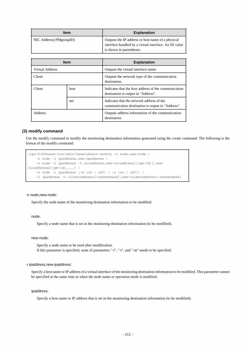
Item Explanation
NIC Address(:PMgroupID) Outputs the IP address or host name of a physicalinterface bundled by a virtual interface. An ID valueis shown in parentheses.
Item Explanation
Virtual Address Outputs the virtual interface name.
Client Outputs the network type of the communicationdestination.
Client host Indicates that the host address of the communicationdestination is output in "Address".
net Indicates that the network address of thecommunication destination is output in "Address".
Address Outputs address information of the communicationdestination.
(3) modify command
Use the modify command to modify the monitoring destination information generated using the create command. The following is theformat of the modify command:
/opt/FJSVhanet/usr/sbin/hanetobserv modify -n node,new-node | -n node -i ipaddress,new-ipaddress | -n node -i ipaddress -t nicaddress,new-nicaddress1[:pm-id][,new-nicaddress2[:pm-id],...] | -n node -i ipaddress {-m {on | off} | -r {on | off}} | -i ipaddress -c clientaddress[:subnetmask],new-clientaddress[:subnetmask]
-n node,new-node:
Specify the node name of the monitoring destination information to be modified.
node:
Specify a node name that is set in the monitoring destination information (to be modified).
new-node:
Specify a node name to be used after modification.If this parameter is specified, none of parameters "-i", "-t", and "-m" needs to be specified.
-i ipaddress,new-ipaddress:
Specify a host name or IP address of a virtual interface of the monitoring destination information to be modified. This parameter cannotbe specified at the same time as when the node name or operation mode is modified.
ipaddress:
Specify a host name or IP address that is set in the monitoring destination information (to be modified).
- 212 -
new-ipaddress:
Specify a host name or IP address to be used after modification.If this parameter is specified, none of new-node in parameter "-n" and parameters "-t" and "-m" needs to be specified.
-t nicaddress,new-nicaddress1[:pm-id][,new-nicaddress2[:pm-id],...]:
Specify the IP address or host name of physical interfaces bundled by a virtual interface of the monitoring information to be modified.This parameter cannot be specified at the same time as when the node name, host name or IP address of the virtual interface, or operationmode is modified.
nicaddress:
Specify the first IP addresses or host names in the IP address or host name list that bundles physical interface that are set in themonitoring destination information (to be modified). Check the first real interface names using the print command of hanetobserv.
Point
If the monitoring target data displayed from executing "hanetobserv print" command contains "ipaddressC,ipaddressD" under "NICAddress(:PMgroupID)" section, in such a case, use the headmost entry or "ipaddressC".
new-nicaddress1[:pm-id][,new-nicaddress2[:pm-id],...]:
Specify all the IP address or host name of a physical interface to be bundled after modification, by listing them delimited with acomma (,).If this parameter is specified, none of new-node in parameter "-n", new-ipaddress in parameter "-i", and parameter "-m" needs tobe specified.
new-nicaddressX:
Specify the host name or IP address of interfaces to be bundled by a virtual interface.
pm-id:
Specify the identifier of the PM (processor module) group to which the physical interface of the communication target belongswhen it is the SURE system. Specify a number from 1 to 8. This option is not required if the communication target is GS.
-m on | off:
Specify the operation mode of the monitoring destination information to be modified.This parameter cannot be simultaneously specified, when changing other parameters.
-r on | off:
Specify the existence of the RIP transmission from a remote system.This parameter cannot be simultaneously specified, when changing other parameters.
-c clientaddress[:subnetmask],new-clientaddress[:subnetmask]:
Modify the host name or IP address of the party with which communication should be actually performed. If a subnet mask value isspecified in the information to be modified, the subnet mask value must be specified for modification.
- 213 -
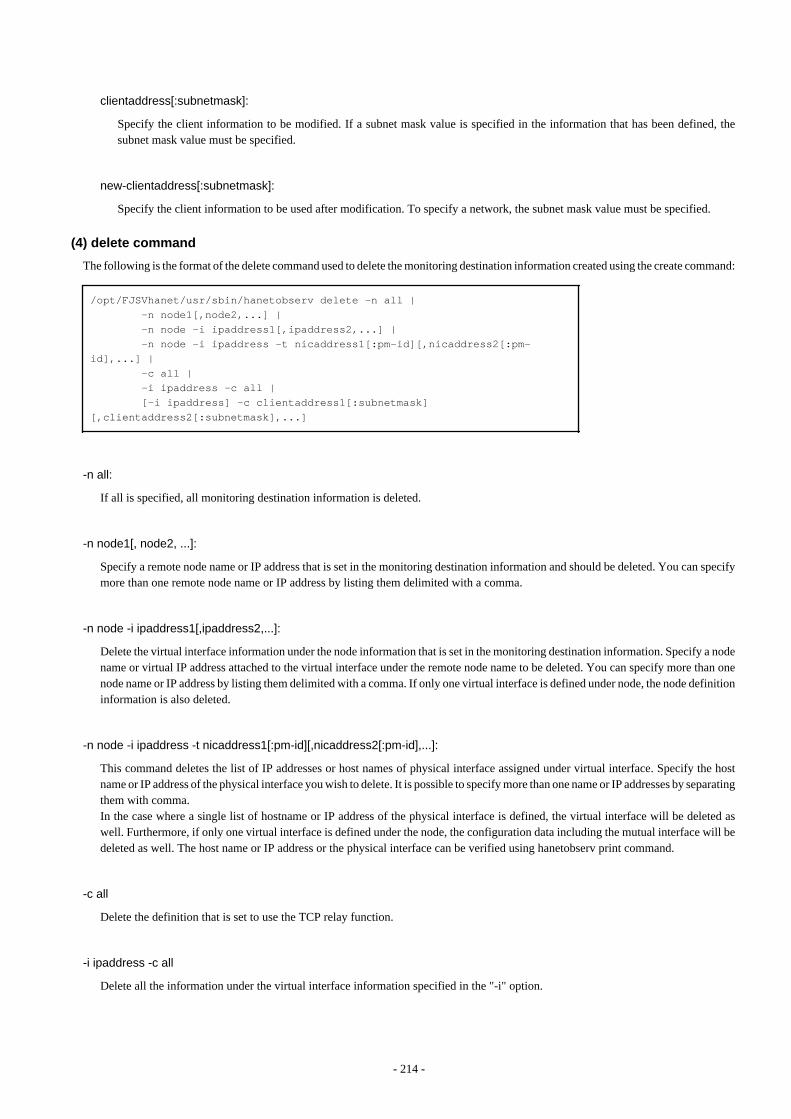
clientaddress[:subnetmask]:
Specify the client information to be modified. If a subnet mask value is specified in the information that has been defined, thesubnet mask value must be specified.
new-clientaddress[:subnetmask]:
Specify the client information to be used after modification. To specify a network, the subnet mask value must be specified.
(4) delete command
The following is the format of the delete command used to delete the monitoring destination information created using the create command:
/opt/FJSVhanet/usr/sbin/hanetobserv delete -n all | -n node1[,node2,...] | -n node -i ipaddress1[,ipaddress2,...] | -n node -i ipaddress -t nicaddress1[:pm-id][,nicaddress2[:pm-id],...] | -c all | -i ipaddress -c all | [-i ipaddress] -c clientaddress1[:subnetmask][,clientaddress2[:subnetmask],...]
-n all:
If all is specified, all monitoring destination information is deleted.
-n node1[, node2, ...]:
Specify a remote node name or IP address that is set in the monitoring destination information and should be deleted. You can specifymore than one remote node name or IP address by listing them delimited with a comma.
-n node -i ipaddress1[,ipaddress2,...]:
Delete the virtual interface information under the node information that is set in the monitoring destination information. Specify a nodename or virtual IP address attached to the virtual interface under the remote node name to be deleted. You can specify more than onenode name or IP address by listing them delimited with a comma. If only one virtual interface is defined under node, the node definitioninformation is also deleted.
-n node -i ipaddress -t nicaddress1[:pm-id][,nicaddress2[:pm-id],...]:
This command deletes the list of IP addresses or host names of physical interface assigned under virtual interface. Specify the hostname or IP address of the physical interface you wish to delete. It is possible to specify more than one name or IP addresses by separatingthem with comma.In the case where a single list of hostname or IP address of the physical interface is defined, the virtual interface will be deleted aswell. Furthermore, if only one virtual interface is defined under the node, the configuration data including the mutual interface will bedeleted as well. The host name or IP address or the physical interface can be verified using hanetobserv print command.
-c all
Delete the definition that is set to use the TCP relay function.
-i ipaddress -c all
Delete all the information under the virtual interface information specified in the "-i" option.
- 214 -
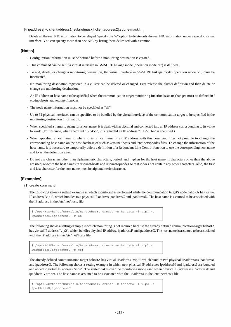
[-i ipaddress] -c clientaddress1[:subnetmask][,clientaddress2[:subnetmask],...]
Delete all the real NIC information to be relayed. Specify the "-i" option to delete only the real NIC information under a specific virtualinterface. You can specify more than one NIC by listing them delimited with a comma.
[Notes]
- Configuration information must be defined before a monitoring destination is created.
- This command can be set if a virtual interface in GS/SURE linkage mode (operation mode "c") is defined.
- To add, delete, or change a monitoring destination, the virtual interface in GS/SURE linkage mode (operation mode "c") must beinactivated.
- No monitoring destination registered in a cluster can be deleted or changed. First release the cluster definition and then delete orchange the monitoring destination.
- An IP address or host name to be specified when the communication target monitoring function is set or changed must be defined in /etc/inet/hosts and /etc/inet/ipnodes.
- The node name information must not be specified as "all".
- Up to 32 physical interfaces can be specified to be bundled by the virtual interface of the communication target to be specified in themonitoring destination information.
- When specified a numeric string for a host name, it is dealt with as decimal and converted into an IP address corresponding to its valueto work. (For instance, when specified "123456", it is regarded an IP address "0.1.226.64" is specified.)
- When specified a host name to where to set a host name or an IP address with this command, it is not possible to change thecorresponding host name on the host database of such as /etc/inet/hosts and /etc/inet/ipnodes files. To change the information of thehost name, it is necessary to temporarily delete a definition of a Redundant Line Control function to use the corresponding host nameand to set the definition again.
- Do not use characters other than alphanumeric characters, period, and hyphen for the host name. If characters other than the aboveare used, re-write the host names in /etc/inet/hosts and /etc/inet/ipnodes so that it does not contain any other characters. Also, the firstand last character for the host name must be alphanumeric character.
[Examples]
(1) create command
The following shows a setting example in which monitoring is performed while the communication target's node hahostA has virtualIP address "vip1", which bundles two physical IP address ipaddressC and ipaddressD. The host name is assumed to be associated withthe IP address in the /etc/inet/hosts file.
# /opt/FJSVhanet/usr/sbin/hanetobserv create -n hahostA -i vip1 -t ipaddressC,ipaddressD -m on
The following shows a setting example in which monitoring is not required because the already defined communication target hahostAhas virtual IP address "vip2", which bundles physical IP address ipaddressF and ipaddressG. The host name is assumed to be associatedwith the IP address in the /etc/inet/hosts file.
# /opt/FJSVhanet/usr/sbin/hanetobserv create -n hahostA -i vip2 -t ipaddressF,ipaddressG -m off
The already defined communication target hahostA has virtual IP address "vip2", which bundles two physical IP addresses ipaddressFand ipaddressG. The following shows a setting example in which new physical IP addresses ipaddressH and ipaddressJ are bundledand added to virtual IP address "vip2". The system takes over the monitoring mode used when physical IP addresses ipaddressF andipaddressG are set. The host name is assumed to be associated with the IP address in the /etc/inet/hosts file.
# /opt/FJSVhanet/usr/sbin/hanetobserv create -n hahostA -i vip2 -t ipaddressH,ipaddressJ
- 215 -
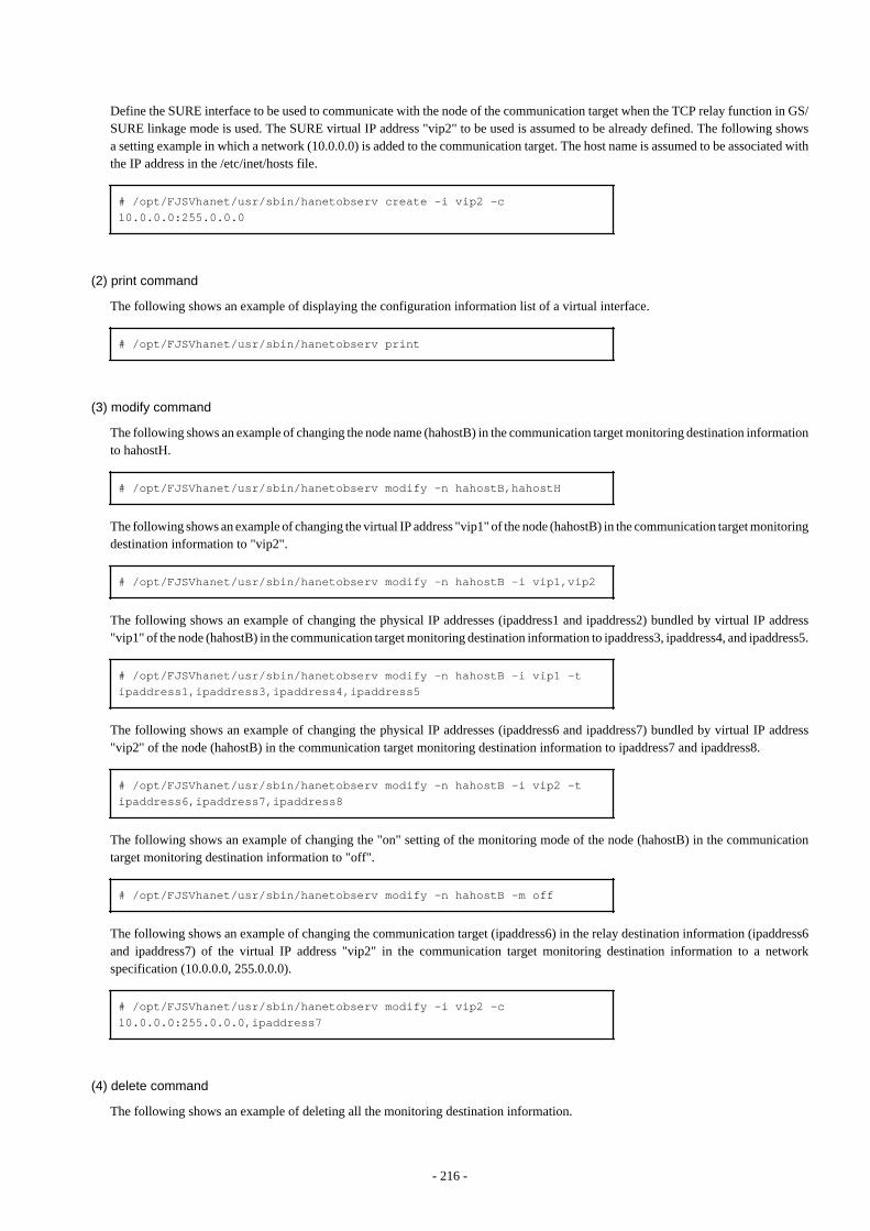
Define the SURE interface to be used to communicate with the node of the communication target when the TCP relay function in GS/SURE linkage mode is used. The SURE virtual IP address "vip2" to be used is assumed to be already defined. The following showsa setting example in which a network (10.0.0.0) is added to the communication target. The host name is assumed to be associated withthe IP address in the /etc/inet/hosts file.
# /opt/FJSVhanet/usr/sbin/hanetobserv create -i vip2 -c 10.0.0.0:255.0.0.0
(2) print command
The following shows an example of displaying the configuration information list of a virtual interface.
# /opt/FJSVhanet/usr/sbin/hanetobserv print
(3) modify command
The following shows an example of changing the node name (hahostB) in the communication target monitoring destination informationto hahostH.
# /opt/FJSVhanet/usr/sbin/hanetobserv modify -n hahostB,hahostH
The following shows an example of changing the virtual IP address "vip1" of the node (hahostB) in the communication target monitoringdestination information to "vip2".
# /opt/FJSVhanet/usr/sbin/hanetobserv modify -n hahostB -i vip1,vip2
The following shows an example of changing the physical IP addresses (ipaddress1 and ipaddress2) bundled by virtual IP address"vip1" of the node (hahostB) in the communication target monitoring destination information to ipaddress3, ipaddress4, and ipaddress5.
# /opt/FJSVhanet/usr/sbin/hanetobserv modify -n hahostB -i vip1 -t ipaddress1,ipaddress3,ipaddress4,ipaddress5
The following shows an example of changing the physical IP addresses (ipaddress6 and ipaddress7) bundled by virtual IP address"vip2" of the node (hahostB) in the communication target monitoring destination information to ipaddress7 and ipaddress8.
# /opt/FJSVhanet/usr/sbin/hanetobserv modify -n hahostB -i vip2 -t ipaddress6,ipaddress7,ipaddress8
The following shows an example of changing the "on" setting of the monitoring mode of the node (hahostB) in the communicationtarget monitoring destination information to "off".
# /opt/FJSVhanet/usr/sbin/hanetobserv modify -n hahostB -m off
The following shows an example of changing the communication target (ipaddress6) in the relay destination information (ipaddress6and ipaddress7) of the virtual IP address "vip2" in the communication target monitoring destination information to a networkspecification (10.0.0.0, 255.0.0.0).
# /opt/FJSVhanet/usr/sbin/hanetobserv modify -i vip2 -c 10.0.0.0:255.0.0.0,ipaddress7
(4) delete command
The following shows an example of deleting all the monitoring destination information.
- 216 -
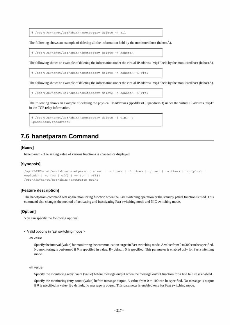
# /opt/FJSVhanet/usr/sbin/hanetobserv delete -n all
The following shows an example of deleting all the information held by the monitored host (hahostA).
# /opt/FJSVhanet/usr/sbin/hanetobserv delete -n hahostA
The following shows an example of deleting the information under the virtual IP address "vip1" held by the monitored host (hahostA).
# /opt/FJSVhanet/usr/sbin/hanetobserv delete -n hahostA -i vip1
The following shows an example of deleting the information under the virtual IP address "vip1" held by the monitored host (hahostA).
# /opt/FJSVhanet/usr/sbin/hanetobserv delete -n hahostA -i vip1
The following shows an example of deleting the physical IP addresses (ipaddressC, ipaddressD) under the virtual IP address "vip1"in the TCP relay information.
# /opt/FJSVhanet/usr/sbin/hanetobserv delete -i vip1 -c ipaddressC,ipaddressD
7.6 hanetparam Command
[Name]
hanetparam - The setting value of various functions is changed or displayed
[Synopsis]
/opt/FJSVhanet/usr/sbin/hanetparam {-w sec | -m times | -l times | -p sec | -o times | -d {plumb | unplumb} | -c {on | off} | -s {on | off}}/opt/FJSVhanet/usr/sbin/hanetparam print
[Feature description]
The hanetparam command sets up the monitoring function when the Fast switching operation or the standby patrol function is used. Thiscommand also changes the method of activating and inactivating Fast switching mode and NIC switching mode.
[Option]
You can specify the following options:
< Valid options in fast switching mode >
-w value
Specify the interval (value) for monitoring the communication target in Fast switching mode. A value from 0 to 300 can be specified.No monitoring is performed if 0 is specified in value. By default, 5 is specified. This parameter is enabled only for Fast switchingmode.
-m value
Specify the monitoring retry count (value) before message output when the message output function for a line failure is enabled.
Specify the monitoring retry count (value) before message output. A value from 0 to 100 can be specified. No message is outputif 0 is specified in value. By default, no message is output. This parameter is enabled only for Fast switching mode.
- 217 -
-l value
Specify the cluster failover function.
Specify how many times (count) communication with the communication target can fail consecutively before cluster failover isperformed. A value from 0 to 100 can be specified. No cluster failover is performed if 0 is specified in value. When performingcluster failover, the number of times for repeating surveillance is specified in the range from 1 time to 100 times until it clusterfailover. By default, cluster failover is specified to be performed if communication fails five consecutive times. This parameter isenabled only for Fast switching mode on a cluster system.
-c value
When operating Fast switching mode on a cluster system and when an error occurred in all transfer routes at the activation of auserApplication, sets if or not to execute failover between clusters (job switching between nodes).Specify "on" to value for executing failover between clusters (job switching between nodes) when an error occurred in all transferroutes at activation of a userApplication.Specify "off" to value for not executing failover between clusters when an error occurred in all transfer routes at activation of auserApplication."off" is set to value as an initial setting value.
-s value
Specify if or not to output a message when a physical interface, which a virtual interface uses, changed the status (detected an errorin a transfer route or recovery). A value possible to specify is "on" or "off". When specified "on", a message is output (messagenumber: 990, 991, and 992). When specified "off", a message is not output. The initial value is "off". This parameter is valid onlyin fast switching mode.
< Valid options in NIC switching mode >
-p value
Specify the interval (value) in seconds for monitoring paths between operation NIC and standby NIC when the standby patrolfunction is enabled. A value from 0 to 100 can be specified. No monitoring is performed if 0 is specified in value. Do not specify 0 to this parameter when set a user command execution function (executing a user command when standby patroldetected an error or recovery). User command execution does not function if specified 0.By default, 15 is specified. This parameter is enabled only for NIC switching mode.
-o value
Specify the monitoring retry count (value) before message output when the message output function for a standby patrol failure isenabled.Specify the monitoring retry count (value) before message output. A value from 0 to 100 can be specified. When specified 0, stop outputting messages and make monitoring by a standby patrol function invalid. Do not specify 0 to thisparameter when set a user command execution function (executing a user command when standby patrol detected an error orrecovery). User command execution does not function, if specified 0.By default, 3 is specified. This parameter is enabled only for NIC switching mode. The number of the times of continuous monitoringis "a set value of this option x 2" immediately after started standby patrol.
-d value
Use this parameter to change the method of inactivating the standby interface in NIC switching mode. Specify "plumb" in valueto inactivate the standby interface and set "0.0.0.0" as the IP address. This procedure allows "INTERSTAGE Traffic Director",etc. to be used as the host application. Alternatively, specify "unplumb" in value to inactivate and delete the standby interface.Initially, "unplumb" is specified in value.
Specify "plumb" for the following situations:
- When configuring high-reliable networks of non-global zones in the shared-ip configuration with the NIC switching mode
- 218 -
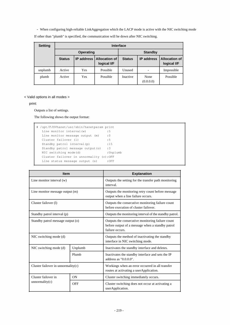
- When configuring high-reliable LinkAggregation which the LACP mode is active with the NIC switching mode
If other than "plumb" is specified, the communication will be down after NIC switching.
Setting Interface
Operating Standby
Status IP address Allocation oflogical I/F
Status IP address Allocation oflogical I/F
unplumb Active Yes Possible Unused - Impossible
plumb Active Yes Possible Inactive None(0.0.0.0)
Possible
< Valid options in all modes >
print:
Outputs a list of settings.
The following shows the output format:
# /opt/FJSVhanet/usr/sbin/hanetparam print Line monitor interval(w) :5 Line monitor message output (m) :0 Cluster failover (l) :5 Standby patrol interval(p) :15 Standby patrol message output(o) :3 NIC switching mode(d) :Unplumb Cluster failover in unnormality (c):OFF Line status message output (s) :OFF
Item Explanation
Line monitor interval (w) Outputs the setting for the transfer path monitoringinterval.
Line monitor message output (m) Outputs the monitoring retry count before messageoutput when a line failure occurs.
Cluster failover (l) Outputs the consecutive monitoring failure countbefore execution of cluster failover.
Standby patrol interval (p) Outputs the monitoring interval of the standby patrol.
Standby patrol message output (o) Outputs the consecutive monitoring failure countbefore output of a message when a standby patrolfailure occurs.
NIC switching mode (d) Outputs the method of inactivating the standbyinterface in NIC switching mode.
NIC switching mode (d) Unplumb Inactivates the standby interface and deletes.
Plumb Inactivates the standby interface and sets the IPaddress as "0.0.0.0".
Cluster failover in unnormality(c) Workings when an error occurred in all transferroutes at activating a userApplication.
Cluster failover inunnormality(c)
ON Cluster switching immediately occurs.
OFF Cluster switching does not occur at activating auserApplication.
- 219 -
Item Explanation
Line status message output (s) With or without a message output when a physicalinterface changed the status.
Line status message output(s)
ON A message is output.
OFF A message is not output.
[Related command]
hanetpoll
[Notes]
- This command can be specified for a virtual interface in Fast switching mode (operation mode "t"), NIC switching mode (operationmode "d" or "e"), and standby patrol function (operation mode "p" or "q").
- The setting by this command is valid in the whole system. It is not possible to change in a unit of virtual interface.
- After executing this command, reboot the system immediately. The applied value will not be effective until the system restarts.
[Examples]
< Example of Fast switching mode >
(1) Example of setting monitoring the communication target interval
The following shows an example of using this command to perform monitoring at intervals of 5 seconds.
# /opt/FJSVhanet/usr/sbin/hanetparam -w 5
(2) Example of enabling or disabling the message output function used when a line failure occurs
The following shows an example of using this command to output a message if communication with the communication target failsfive consecutive times.
# /opt/FJSVhanet/usr/sbin/hanetparam -m 5
(3) Example of setting the cluster failover function
The following shows an example of using this command to perform cluster failover if communication with the communication targetfails five consecutive times.
# /opt/FJSVhanet/usr/sbin/hanetparam -l 5
(4) A setting example of the workings when an error occurred in every transfer route at the activation of a userApplication
An example of a command to execute failover between clusters when an error occurred in every transfer route immediately afteractivated a userApplication is as follows:
# /opt/FJSVhanet/usr/sbin/hanetparam -c on
(5) An example of setting with/without outputting a message when a physical interface, which a virtual interfaces uses, changedthe status
- 220 -
An example of a command to output a message when a physical interface, which a virtual interface uses, changed the status is asfollows:
# /opt/FJSVhanet/usr/sbin/hanetparam -s on
< Example of NIC switching mode >
(1) Example of setting the standby patrol monitoring interval
The following shows an example of using this command to perform monitoring at intervals of five seconds.
# /opt/FJSVhanet/usr/sbin/hanetparam -p 5
(2) Example of setting the message output function used when a standby patrol failure occurs
The following shows an example of using this command to output a message when communication with the communication targetfails five consecutive times.
# /opt/FJSVhanet/usr/sbin/hanetparam -o 5
(3) Example of changing the method of inactivating the standby interface
The following shows an example of using this command to inactivate the standby interface and set "0.0.0.0" as the IP address (using"INTERSTAGE Traffic Director", Solaris Zones, etc. as the host application).
# /opt/FJSVhanet/usr/sbin/hanetparam -d plumb
< Example common to all modes >
(1) Example of executing the status display command
The following shows an example of displaying the settings made using the hanetparam command.
# /opt/FJSVhanet/usr/sbin/hanetparam print
7.7 hanetpoll Command
[Name]
hanetpoll - Setting, modifying, deleting, and displaying the monitoring destination information for the HUB monitoring function
[Synopsis]
/opt/FJSVhanet/usr/sbin/hanetpoll command [args]
[Feature description]
The hanetpoll command sets the monitoring destination information required for the HUB monitoring function. This command alsomodifies, deletes, displays, enables, or disables the settings.
command Process outline Authority
create Creates monitoring destination information Super user
- 221 -
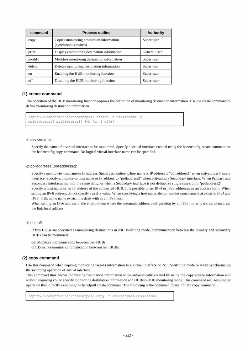
command Process outline Authority
copy Copies monitoring destination information(synchronous switch)
Super user
print Displays monitoring destination information General user
modify Modifies monitoring destination information Super user
delete Deletes monitoring destination information Super user
on Enabling the HUB monitoring function Super user
off Disabling the HUB monitoring function Super user
(1) create command
The operation of the HUB monitoring function requires the definition of monitoring destination information. Use the create command todefine monitoring destination information.
/opt/FJSVhanet/usr/sbin/hanetpoll create -n devicename -p polladdress1[,polladdress2] [-b {on | off}]
-n devicename:
Specify the name of a virtual interface to be monitored. Specify a virtual interface created using the hanetconfig create command orthe hanetconfig copy command. No logical virtual interface name can be specified.
-p polladdress1[,polladdress2]:
Specify a monitor-to host name or IP address. Specify a monitor-to host name or IP address to "polladdress1" when activating a Primaryinterface. Specify a monitor-to host name or IP address to "polladdress2" when activating a Secondary interface. When Primary andSecondary interfaces monitor the same thing, or when a Secondary interface is not defined (a single case), omit "polladdress2".Specify a host name or an IP address of the connected HUB. It is possible to set IPv4 or IPv6 addresses as an address form. Whensetting an IPv6 address, do not specify a prefix value. When specifying a host name, do not use the same name that exists in IPv4 andIPv6. If the same name exists, it is dealt with as an IPv6 host.When setting an IPv6 address in the environment where the automatic address configuration by an IPv6 router is not performed, setthe link-local address.
-b on | off:
If two HUBs are specified as monitoring destinations in NIC switching mode, communication between the primary and secondaryHUBs can be monitored.
on: Monitors communication between two HUBs.off: Does not monitor communication between two HUBs.
(2) copy command
Use this command when copying monitoring target's information to a virtual interface on NIC Switching mode or when synchronizingthe switching operation of virtual interface.This command thus allows monitoring destination information to be automatically created by using the copy source information andwithout requiring you to specify monitoring destination information and HUB-to-HUB monitoring mode. This command realizes simpleroperation than directly executing the hanetpoll create command. The following is the command format for the copy command:
/opt/FJSVhanet/usr/sbin/hanetpoll copy -n devicename1,devicename2
- 222 -

Point
If you have used tagged VLAN interface on NIC Switching mode and created more than one virtual interface, which have disparate networkaddress, you must keep in account that multiple IP address cannot be configured as monitoring target on Switch/HUB running VLAN. Insuch a case, it is possible to implement synchronous switching in between virtual interfaces using the same physical interface. This allowsa virtual interface, which does not have the IP address for monitoring target to perform fail back operation by synchronizing with a virtualinterface, which already has the existing monitoring target. In order to synchronize the switching operation of virtual interface, use the"copy" command (it is possible to specify disparate network addresses).
-n devicename1,devicename2:
Specify the names of virtual interfaces from and to which monitoring destination information should be copied.
devicename1:
Specify the name of a virtual interface that is set in monitoring information in the copy source.
devicename2:
Specify the name of a new virtual interface to be monitored. Specify a virtual interface created using the hanetconfig create commandor the hanetconfig copy command. No logical virtual interface name can be specified.
(3) print command
Use the print command to display the current monitoring destination information. Use this command to view the current monitoringdestination information. The following is the format of the print command.
/opt/FJSVhanet/usr/sbin/hanetpoll print [-n devicename1[,devicename2,...]]
-n devicename1[,devicename2,...]:
Specify the names of virtual interfaces whose monitoring destination information should be displayed. If this option is not specified,the print command displays all the monitoring destination information currently specified.
The following shows an example of displaying information without any option specified.
# /opt/FJSVhanet/usr/sbin/hanetpoll print[ Standard Polling Parameter ] interval(idle) = 5( 60) sec times = 5 times max_retry = 5 retry repair_time = 5 sec link detection = NO failover mode = YES
[ Polling Parameter of each interface ] Name Hostname/Polling Parameter+-------+------------------------------------------------------+ sha0 swhub1,swhub2 hub-hub poll = OFF interval(idle) = 5( 60) sec times = 5 times max_retry = 5 retry repair_time = 5 sec link detection = NO failover mode = YES
- 223 -

Name Hostname/Polling Parameter+-------+------------------------------------------------------+ sha1 swhub3,swhub4 hub-hub poll = OFF interval(idle) = 5( 60) sec times = 5 times max_retry = 5 retry repair_time = 5 sec link detection = NO failover mode = YES
Item Explanation
Standard Polling Parameter Common monitoring information
Polling Parameter of each interface Each monitoring information
Name Displays the name of a virtual interface to bemonitored.
Hostname Displays the host name or IP address to be monitored,in the order of the primary and secondary monitoringdestinations.
hub-hub poll Displays the inter-HUB monitoring status.
hub-hub poll ON The monitoring function is enabled.
OFF The monitoring function is disabled.
--- The monitoring function is not used.
interval(idle) interval Displays the monitoring interval in the stationarystatus.
idle Displays in seconds the wait time that elapses aftermonitoring starts and before the HUB links up.
times Displays the monitoring count.
max_retry Displays the consecutive failure occurrence countbefore failure notification.
repair_time Displays the recovery monitoring interval in seconds.
link detection YES Detects link-based failures.
NO Does not detect link-based failures.
failover mode With or without cluster switching when an erroroccurred in all transfer routes.
failover mode YES Node switching is performed when the virtualinterface is registered in the cluster resource.
NO No node switching is performed.
(4) modify command
Use the modify command to modify the monitoring destination information.
/opt/FJSVhanet/usr/sbin/hanetpoll modify -n devicename {[-p polladdress1[,polladdress2]] [-b {on | off}]}
- 224 -
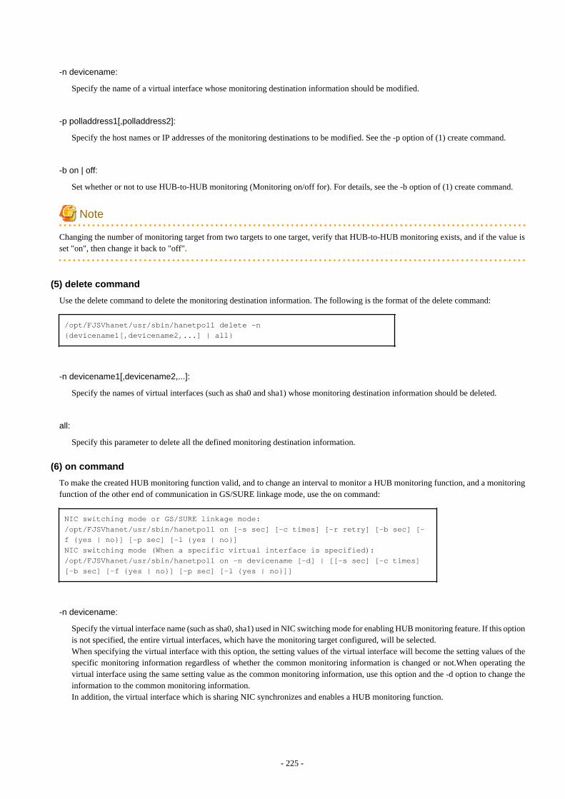
-n devicename:
Specify the name of a virtual interface whose monitoring destination information should be modified.
-p polladdress1[,polladdress2]:
Specify the host names or IP addresses of the monitoring destinations to be modified. See the -p option of (1) create command.
-b on | off:
Set whether or not to use HUB-to-HUB monitoring (Monitoring on/off for). For details, see the -b option of (1) create command.
Note
Changing the number of monitoring target from two targets to one target, verify that HUB-to-HUB monitoring exists, and if the value isset "on", then change it back to "off".
(5) delete command
Use the delete command to delete the monitoring destination information. The following is the format of the delete command:
/opt/FJSVhanet/usr/sbin/hanetpoll delete -n {devicename1[,devicename2,...] | all}
-n devicename1[,devicename2,...]:
Specify the names of virtual interfaces (such as sha0 and sha1) whose monitoring destination information should be deleted.
all:
Specify this parameter to delete all the defined monitoring destination information.
(6) on command
To make the created HUB monitoring function valid, and to change an interval to monitor a HUB monitoring function, and a monitoringfunction of the other end of communication in GS/SURE linkage mode, use the on command:
NIC switching mode or GS/SURE linkage mode:/opt/FJSVhanet/usr/sbin/hanetpoll on [-s sec] [-c times] [-r retry] [-b sec] [-f {yes | no}] [-p sec] [-l {yes | no}]NIC switching mode (When a specific virtual interface is specified):/opt/FJSVhanet/usr/sbin/hanetpoll on -n devicename [-d] | [[-s sec] [-c times] [-b sec] [-f {yes | no}] [-p sec] [-l {yes | no}]]
-n devicename:
Specify the virtual interface name (such as sha0, sha1) used in NIC switching mode for enabling HUB monitoring feature. If this optionis not specified, the entire virtual interfaces, which have the monitoring target configured, will be selected. When specifying the virtual interface with this option, the setting values of the virtual interface will become the setting values of thespecific monitoring information regardless of whether the common monitoring information is changed or not.When operating thevirtual interface using the same setting value as the common monitoring information, use this option and the -d option to change theinformation to the common monitoring information.In addition, the virtual interface which is sharing NIC synchronizes and enables a HUB monitoring function.
- 225 -
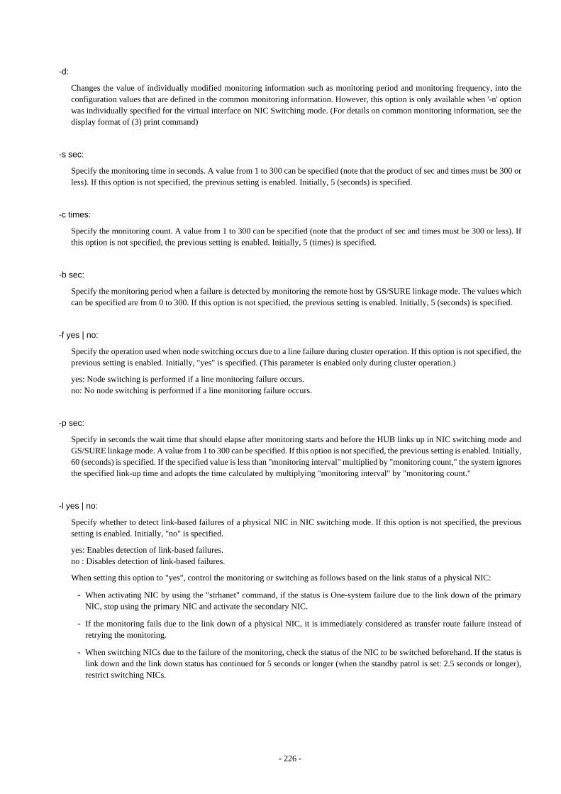
-d:
Changes the value of individually modified monitoring information such as monitoring period and monitoring frequency, into theconfiguration values that are defined in the common monitoring information. However, this option is only available when '-n' optionwas individually specified for the virtual interface on NIC Switching mode. (For details on common monitoring information, see thedisplay format of (3) print command)
-s sec:
Specify the monitoring time in seconds. A value from 1 to 300 can be specified (note that the product of sec and times must be 300 orless). If this option is not specified, the previous setting is enabled. Initially, 5 (seconds) is specified.
-c times:
Specify the monitoring count. A value from 1 to 300 can be specified (note that the product of sec and times must be 300 or less). Ifthis option is not specified, the previous setting is enabled. Initially, 5 (times) is specified.
-b sec:
Specify the monitoring period when a failure is detected by monitoring the remote host by GS/SURE linkage mode. The values whichcan be specified are from 0 to 300. If this option is not specified, the previous setting is enabled. Initially, 5 (seconds) is specified.
-f yes | no:
Specify the operation used when node switching occurs due to a line failure during cluster operation. If this option is not specified, theprevious setting is enabled. Initially, "yes" is specified. (This parameter is enabled only during cluster operation.)
yes: Node switching is performed if a line monitoring failure occurs.no: No node switching is performed if a line monitoring failure occurs.
-p sec:
Specify in seconds the wait time that should elapse after monitoring starts and before the HUB links up in NIC switching mode andGS/SURE linkage mode. A value from 1 to 300 can be specified. If this option is not specified, the previous setting is enabled. Initially,60 (seconds) is specified. If the specified value is less than "monitoring interval" multiplied by "monitoring count," the system ignoresthe specified link-up time and adopts the time calculated by multiplying "monitoring interval" by "monitoring count."
-l yes | no:
Specify whether to detect link-based failures of a physical NIC in NIC switching mode. If this option is not specified, the previoussetting is enabled. Initially, "no" is specified.
yes: Enables detection of link-based failures.no : Disables detection of link-based failures.
When setting this option to "yes", control the monitoring or switching as follows based on the link status of a physical NIC:
- When activating NIC by using the "strhanet" command, if the status is One-system failure due to the link down of the primaryNIC, stop using the primary NIC and activate the secondary NIC.
- If the monitoring fails due to the link down of a physical NIC, it is immediately considered as transfer route failure instead ofretrying the monitoring.
- When switching NICs due to the failure of the monitoring, check the status of the NIC to be switched beforehand. If the status islink down and the link down status has continued for 5 seconds or longer (when the standby patrol is set: 2.5 seconds or longer),restrict switching NICs.
- 226 -
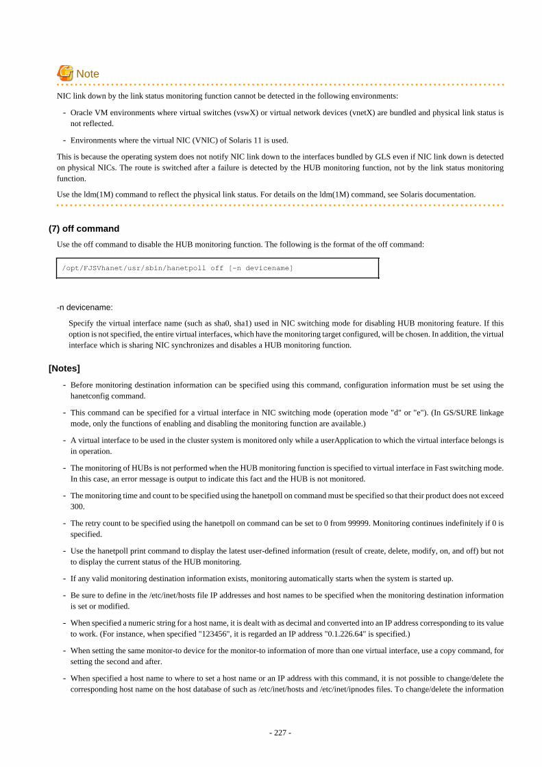
Note
NIC link down by the link status monitoring function cannot be detected in the following environments:
- Oracle VM environments where virtual switches (vswX) or virtual network devices (vnetX) are bundled and physical link status isnot reflected.
- Environments where the virtual NIC (VNIC) of Solaris 11 is used.
This is because the operating system does not notify NIC link down to the interfaces bundled by GLS even if NIC link down is detectedon physical NICs. The route is switched after a failure is detected by the HUB monitoring function, not by the link status monitoringfunction.
Use the ldm(1M) command to reflect the physical link status. For details on the ldm(1M) command, see Solaris documentation.
(7) off command
Use the off command to disable the HUB monitoring function. The following is the format of the off command:
/opt/FJSVhanet/usr/sbin/hanetpoll off [-n devicename]
-n devicename:
Specify the virtual interface name (such as sha0, sha1) used in NIC switching mode for disabling HUB monitoring feature. If thisoption is not specified, the entire virtual interfaces, which have the monitoring target configured, will be chosen. In addition, the virtualinterface which is sharing NIC synchronizes and disables a HUB monitoring function.
[Notes]
- Before monitoring destination information can be specified using this command, configuration information must be set using thehanetconfig command.
- This command can be specified for a virtual interface in NIC switching mode (operation mode "d" or "e"). (In GS/SURE linkagemode, only the functions of enabling and disabling the monitoring function are available.)
- A virtual interface to be used in the cluster system is monitored only while a userApplication to which the virtual interface belongs isin operation.
- The monitoring of HUBs is not performed when the HUB monitoring function is specified to virtual interface in Fast switching mode.In this case, an error message is output to indicate this fact and the HUB is not monitored.
- The monitoring time and count to be specified using the hanetpoll on command must be specified so that their product does not exceed300.
- The retry count to be specified using the hanetpoll on command can be set to 0 from 99999. Monitoring continues indefinitely if 0 isspecified.
- Use the hanetpoll print command to display the latest user-defined information (result of create, delete, modify, on, and off) but notto display the current status of the HUB monitoring.
- If any valid monitoring destination information exists, monitoring automatically starts when the system is started up.
- Be sure to define in the /etc/inet/hosts file IP addresses and host names to be specified when the monitoring destination informationis set or modified.
- When specified a numeric string for a host name, it is dealt with as decimal and converted into an IP address corresponding to its valueto work. (For instance, when specified "123456", it is regarded an IP address "0.1.226.64" is specified.)
- When setting the same monitor-to device for the monitor-to information of more than one virtual interface, use a copy command, forsetting the second and after.
- When specified a host name to where to set a host name or an IP address with this command, it is not possible to change/delete thecorresponding host name on the host database of such as /etc/inet/hosts and /etc/inet/ipnodes files. To change/delete the information
- 227 -
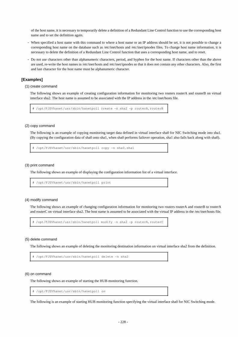
of the host name, it is necessary to temporarily delete a definition of a Redundant Line Control function to use the corresponding hostname and to set the definition again.
- When specified a host name with this command to where a host name or an IP address should be set, it is not possible to change acorresponding host name on the database such as /etc/inet/hosts and /etc/inet/ipnodes files. To change host name information, it isnecessary to delete the definition of a Redundant Line Control function that uses a corresponding host name, and to reset.
- Do not use characters other than alphanumeric characters, period, and hyphen for the host name. If characters other than the aboveare used, re-write the host names in /etc/inet/hosts and /etc/inet/ipnodes so that it does not contain any other characters. Also, the firstand last character for the host name must be alphanumeric character.
[Examples]
(1) create command
The following shows an example of creating configuration information for monitoring two routers routerA and routerB on virtualinterface sha2. The host name is assumed to be associated with the IP address in the /etc/inet/hosts file.
# /opt/FJSVhanet/usr/sbin/hanetpoll create -n sha2 -p routerA,routerB
(2) copy command
The following is an example of copying monitoring target data defined in virtual interface sha0 for NIC Switching mode into sha1.(By copying the configuration data of sha0 onto sha1, when sha0 performs failover operation, sha1 also fails back along with sha0).
# /opt/FJSVhanet/usr/sbin/hanetpoll copy -n sha0,sha1
(3) print command
The following shows an example of displaying the configuration information list of a virtual interface.
# /opt/FJSVhanet/usr/sbin/hanetpoll print
(4) modify command
The following shows an example of changing configuration information for monitoring two routers routerA and routerB to routerAand routerC on virtual interface sha2. The host name is assumed to be associated with the virtual IP address in the /etc/inet/hosts file.
# /opt/FJSVhanet/usr/sbin/hanetpoll modify -n sha2 -p routerA,routerC
(5) delete command
The following shows an example of deleting the monitoring destination information on virtual interface sha2 from the definition.
# /opt/FJSVhanet/usr/sbin/hanetpoll delete -n sha2
(6) on command
The following shows an example of starting the HUB monitoring function.
# /opt/FJSVhanet/usr/sbin/hanetpoll on
The following is an example of starting HUB monitoring function specifying the virtual interface sha0 for NIC Switching mode.
- 228 -
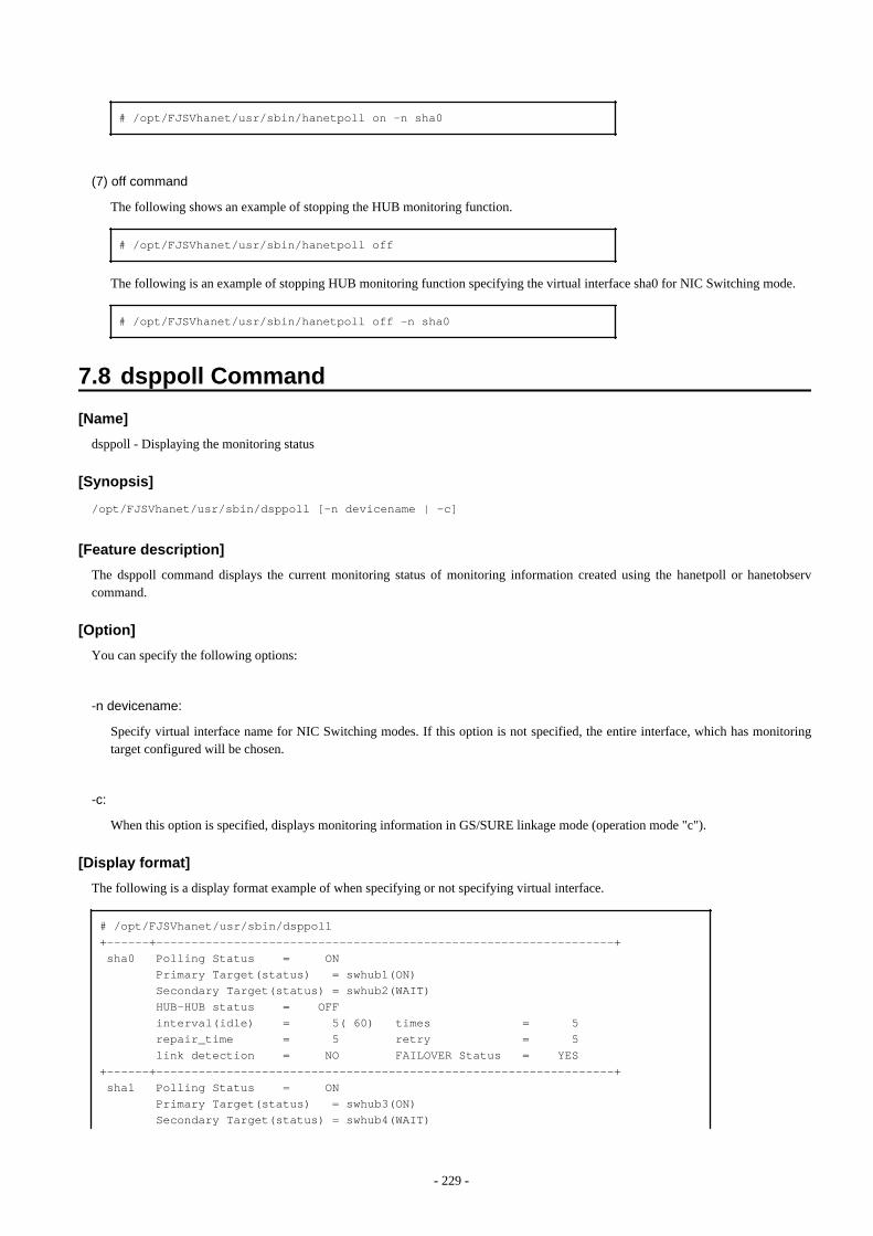
# /opt/FJSVhanet/usr/sbin/hanetpoll on -n sha0
(7) off command
The following shows an example of stopping the HUB monitoring function.
# /opt/FJSVhanet/usr/sbin/hanetpoll off
The following is an example of stopping HUB monitoring function specifying the virtual interface sha0 for NIC Switching mode.
# /opt/FJSVhanet/usr/sbin/hanetpoll off -n sha0
7.8 dsppoll Command
[Name]
dsppoll - Displaying the monitoring status
[Synopsis]
/opt/FJSVhanet/usr/sbin/dsppoll [-n devicename | -c]
[Feature description]
The dsppoll command displays the current monitoring status of monitoring information created using the hanetpoll or hanetobservcommand.
[Option]
You can specify the following options:
-n devicename:
Specify virtual interface name for NIC Switching modes. If this option is not specified, the entire interface, which has monitoringtarget configured will be chosen.
-c:
When this option is specified, displays monitoring information in GS/SURE linkage mode (operation mode "c").
[Display format]
The following is a display format example of when specifying or not specifying virtual interface.
# /opt/FJSVhanet/usr/sbin/dsppoll+------+-----------------------------------------------------------------+ sha0 Polling Status = ON Primary Target(status) = swhub1(ON) Secondary Target(status) = swhub2(WAIT) HUB-HUB status = OFF interval(idle) = 5( 60) times = 5 repair_time = 5 retry = 5 link detection = NO FAILOVER Status = YES+------+-----------------------------------------------------------------+ sha1 Polling Status = ON Primary Target(status) = swhub3(ON) Secondary Target(status) = swhub4(WAIT)
- 229 -
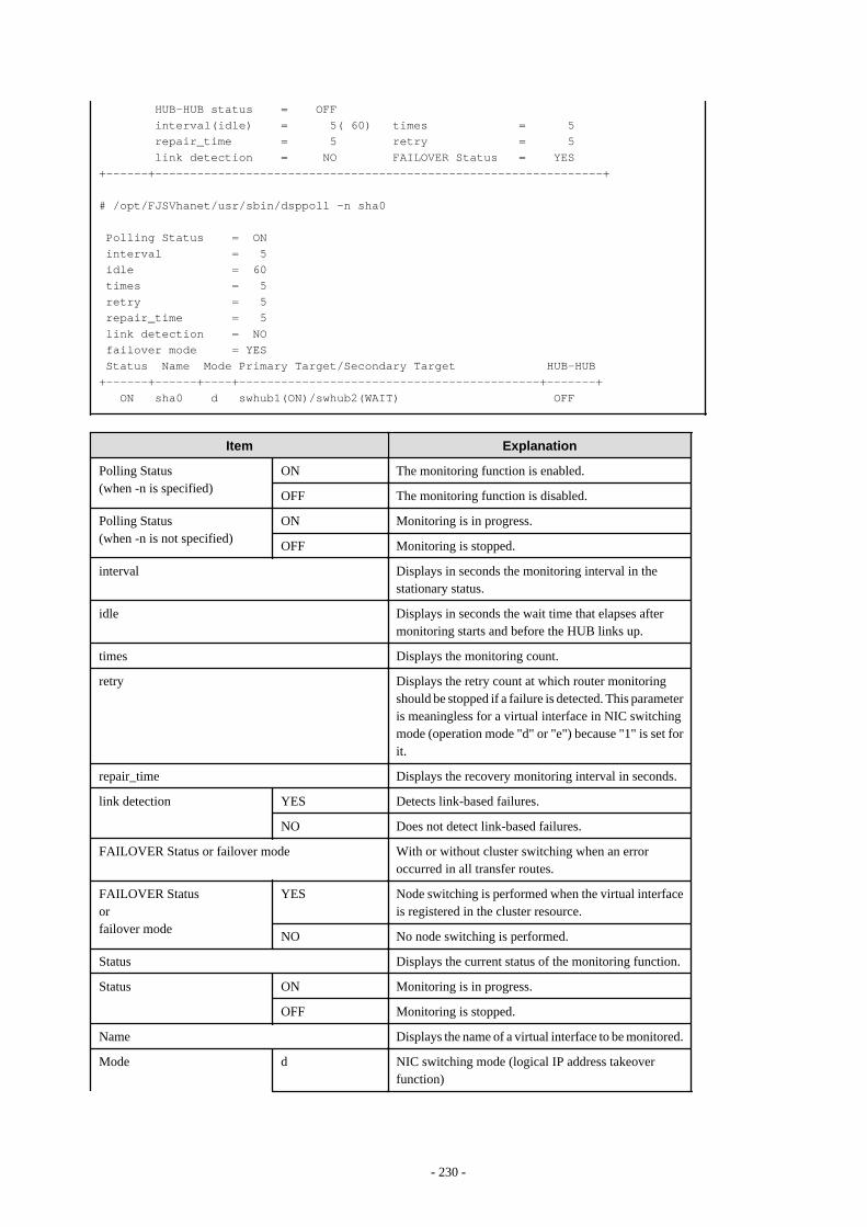
HUB-HUB status = OFF interval(idle) = 5( 60) times = 5 repair_time = 5 retry = 5 link detection = NO FAILOVER Status = YES+------+----------------------------------------------------------------+
# /opt/FJSVhanet/usr/sbin/dsppoll -n sha0
Polling Status = ON interval = 5 idle = 60 times = 5 retry = 5 repair_time = 5 link detection = NO failover mode = YES Status Name Mode Primary Target/Secondary Target HUB-HUB+------+------+----+-------------------------------------------+-------+ ON sha0 d swhub1(ON)/swhub2(WAIT) OFF
Item Explanation
Polling Status(when -n is specified)
ON The monitoring function is enabled.
OFF The monitoring function is disabled.
Polling Status(when -n is not specified)
ON Monitoring is in progress.
OFF Monitoring is stopped.
interval Displays in seconds the monitoring interval in thestationary status.
idle Displays in seconds the wait time that elapses aftermonitoring starts and before the HUB links up.
times Displays the monitoring count.
retry Displays the retry count at which router monitoringshould be stopped if a failure is detected. This parameteris meaningless for a virtual interface in NIC switchingmode (operation mode "d" or "e") because "1" is set forit.
repair_time Displays the recovery monitoring interval in seconds.
link detection YES Detects link-based failures.
NO Does not detect link-based failures.
FAILOVER Status or failover mode With or without cluster switching when an erroroccurred in all transfer routes.
FAILOVER Statusorfailover mode
YES Node switching is performed when the virtual interfaceis registered in the cluster resource.
NO No node switching is performed.
Status Displays the current status of the monitoring function.
Status ON Monitoring is in progress.
OFF Monitoring is stopped.
Name Displays the name of a virtual interface to be monitored.
Mode d NIC switching mode (logical IP address takeoverfunction)
- 230 -
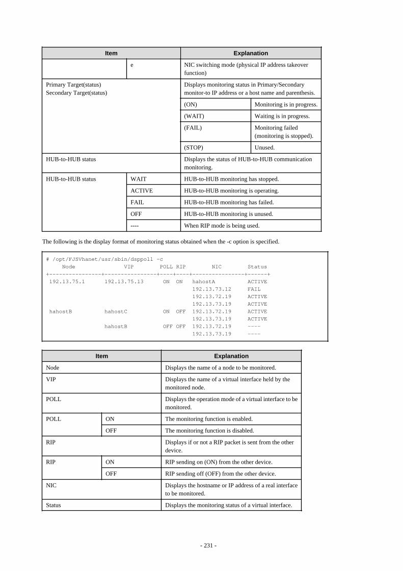
Item Explanation
e NIC switching mode (physical IP address takeoverfunction)
Primary Target(status)Secondary Target(status)
Displays monitoring status in Primary/Secondarymonitor-to IP address or a host name and parenthesis.
(ON) Monitoring is in progress.
(WAIT) Waiting is in progress.
(FAIL) Monitoring failed(monitoring is stopped).
(STOP) Unused.
HUB-to-HUB status Displays the status of HUB-to-HUB communicationmonitoring.
HUB-to-HUB status WAIT HUB-to-HUB monitoring has stopped.
ACTIVE HUB-to-HUB monitoring is operating.
FAIL HUB-to-HUB monitoring has failed.
OFF HUB-to-HUB monitoring is unused.
---- When RIP mode is being used.
The following is the display format of monitoring status obtained when the -c option is specified.
# /opt/FJSVhanet/usr/sbin/dsppoll -c Node VIP POLL RIP NIC Status+----------------+----------------+----+----+----------------+------+ 192.13.75.1 192.13.75.13 ON ON hahostA ACTIVE 192.13.73.12 FAIL 192.13.72.19 ACTIVE 192.13.73.19 ACTIVE hahostB hahostC ON OFF 192.13.72.19 ACTIVE 192.13.73.19 ACTIVE hahostB OFF OFF 192.13.72.19 ---- 192.13.73.19 ----
Item Explanation
Node Displays the name of a node to be monitored.
VIP Displays the name of a virtual interface held by themonitored node.
POLL Displays the operation mode of a virtual interface to bemonitored.
POLL ON The monitoring function is enabled.
OFF The monitoring function is disabled.
RIP Displays if or not a RIP packet is sent from the otherdevice.
RIP ON RIP sending on (ON) from the other device.
OFF RIP sending off (OFF) from the other device.
NIC Displays the hostname or IP address of a real interfaceto be monitored.
Status Displays the monitoring status of a virtual interface.
- 231 -
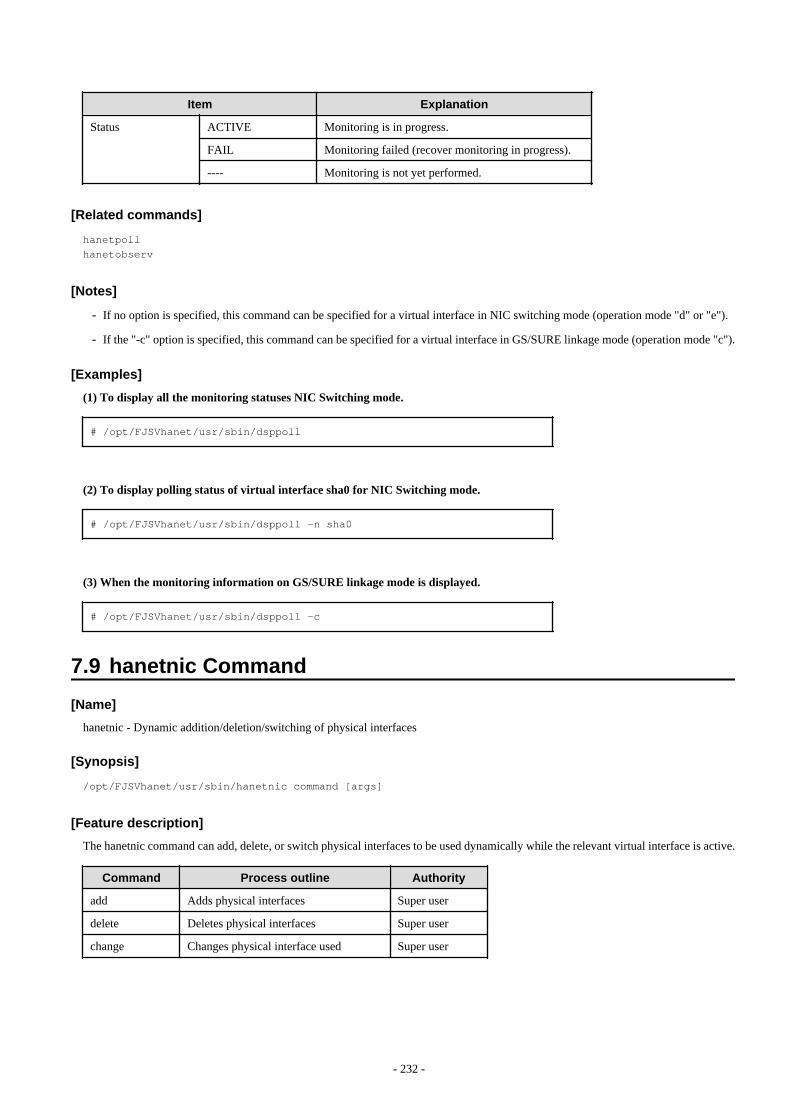
Item Explanation
Status ACTIVE Monitoring is in progress.
FAIL Monitoring failed (recover monitoring in progress).
---- Monitoring is not yet performed.
[Related commands]
hanetpollhanetobserv
[Notes]
- If no option is specified, this command can be specified for a virtual interface in NIC switching mode (operation mode "d" or "e").
- If the "-c" option is specified, this command can be specified for a virtual interface in GS/SURE linkage mode (operation mode "c").
[Examples]
(1) To display all the monitoring statuses NIC Switching mode.
# /opt/FJSVhanet/usr/sbin/dsppoll
(2) To display polling status of virtual interface sha0 for NIC Switching mode.
# /opt/FJSVhanet/usr/sbin/dsppoll -n sha0
(3) When the monitoring information on GS/SURE linkage mode is displayed.
# /opt/FJSVhanet/usr/sbin/dsppoll -c
7.9 hanetnic Command
[Name]
hanetnic - Dynamic addition/deletion/switching of physical interfaces
[Synopsis]
/opt/FJSVhanet/usr/sbin/hanetnic command [args]
[Feature description]
The hanetnic command can add, delete, or switch physical interfaces to be used dynamically while the relevant virtual interface is active.
Command Process outline Authority
add Adds physical interfaces Super user
delete Deletes physical interfaces Super user
change Changes physical interface used Super user
- 232 -
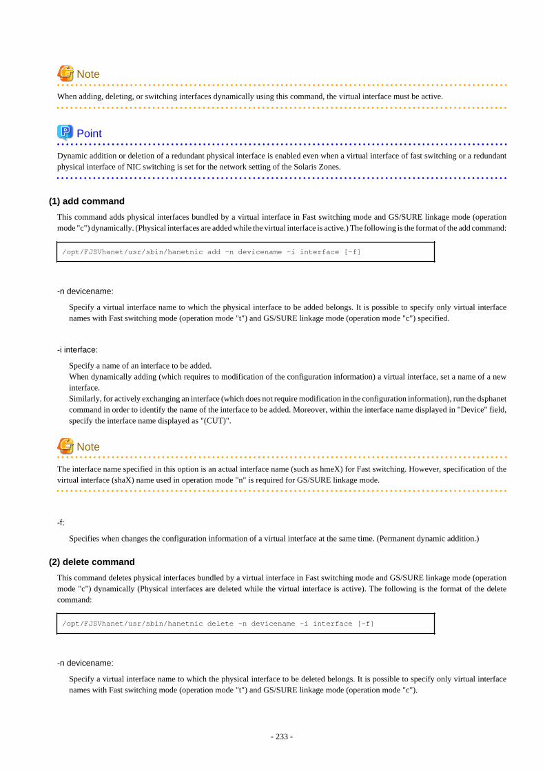
Note
When adding, deleting, or switching interfaces dynamically using this command, the virtual interface must be active.
Point
Dynamic addition or deletion of a redundant physical interface is enabled even when a virtual interface of fast switching or a redundantphysical interface of NIC switching is set for the network setting of the Solaris Zones.
(1) add command
This command adds physical interfaces bundled by a virtual interface in Fast switching mode and GS/SURE linkage mode (operationmode "c") dynamically. (Physical interfaces are added while the virtual interface is active.) The following is the format of the add command:
/opt/FJSVhanet/usr/sbin/hanetnic add -n devicename -i interface [-f]
-n devicename:
Specify a virtual interface name to which the physical interface to be added belongs. It is possible to specify only virtual interfacenames with Fast switching mode (operation mode "t") and GS/SURE linkage mode (operation mode "c") specified.
-i interface:
Specify a name of an interface to be added.When dynamically adding (which requires to modification of the configuration information) a virtual interface, set a name of a newinterface.Similarly, for actively exchanging an interface (which does not require modification in the configuration information), run the dsphanetcommand in order to identify the name of the interface to be added. Moreover, within the interface name displayed in "Device" field,specify the interface name displayed as "(CUT)".
Note
The interface name specified in this option is an actual interface name (such as hmeX) for Fast switching. However, specification of thevirtual interface (shaX) name used in operation mode "n" is required for GS/SURE linkage mode.
-f:
Specifies when changes the configuration information of a virtual interface at the same time. (Permanent dynamic addition.)
(2) delete command
This command deletes physical interfaces bundled by a virtual interface in Fast switching mode and GS/SURE linkage mode (operationmode "c") dynamically (Physical interfaces are deleted while the virtual interface is active). The following is the format of the deletecommand:
/opt/FJSVhanet/usr/sbin/hanetnic delete -n devicename -i interface [-f]
-n devicename:
Specify a virtual interface name to which the physical interface to be deleted belongs. It is possible to specify only virtual interfacenames with Fast switching mode (operation mode "t") and GS/SURE linkage mode (operation mode "c").
- 233 -
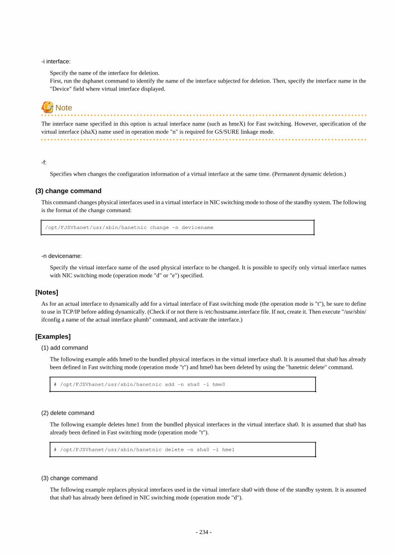
-i interface:
Specify the name of the interface for deletion.First, run the dsphanet command to identify the name of the interface subjected for deletion. Then, specify the interface name in the"Device" field where virtual interface displayed.
Note
The interface name specified in this option is actual interface name (such as hmeX) for Fast switching. However, specification of thevirtual interface (shaX) name used in operation mode "n" is required for GS/SURE linkage mode.
-f:
Specifies when changes the configuration information of a virtual interface at the same time. (Permanent dynamic deletion.)
(3) change command
This command changes physical interfaces used in a virtual interface in NIC switching mode to those of the standby system. The followingis the format of the change command:
/opt/FJSVhanet/usr/sbin/hanetnic change -n devicename
-n devicename:
Specify the virtual interface name of the used physical interface to be changed. It is possible to specify only virtual interface nameswith NIC switching mode (operation mode "d" or "e") specified.
[Notes]
As for an actual interface to dynamically add for a virtual interface of Fast switching mode (the operation mode is "t"), be sure to defineto use in TCP/IP before adding dynamically. (Check if or not there is /etc/hostname.interface file. If not, create it. Then execute "/usr/sbin/ifconfig a name of the actual interface plumb" command, and activate the interface.)
[Examples]
(1) add command
The following example adds hme0 to the bundled physical interfaces in the virtual interface sha0. It is assumed that sha0 has alreadybeen defined in Fast switching mode (operation mode "t") and hme0 has been deleted by using the "hanetnic delete" command.
# /opt/FJSVhanet/usr/sbin/hanetnic add -n sha0 -i hme0
(2) delete command
The following example deletes hme1 from the bundled physical interfaces in the virtual interface sha0. It is assumed that sha0 hasalready been defined in Fast switching mode (operation mode "t").
# /opt/FJSVhanet/usr/sbin/hanetnic delete -n sha0 -i hme1
(3) change command
The following example replaces physical interfaces used in the virtual interface sha0 with those of the standby system. It is assumedthat sha0 has already been defined in NIC switching mode (operation mode "d").
- 234 -
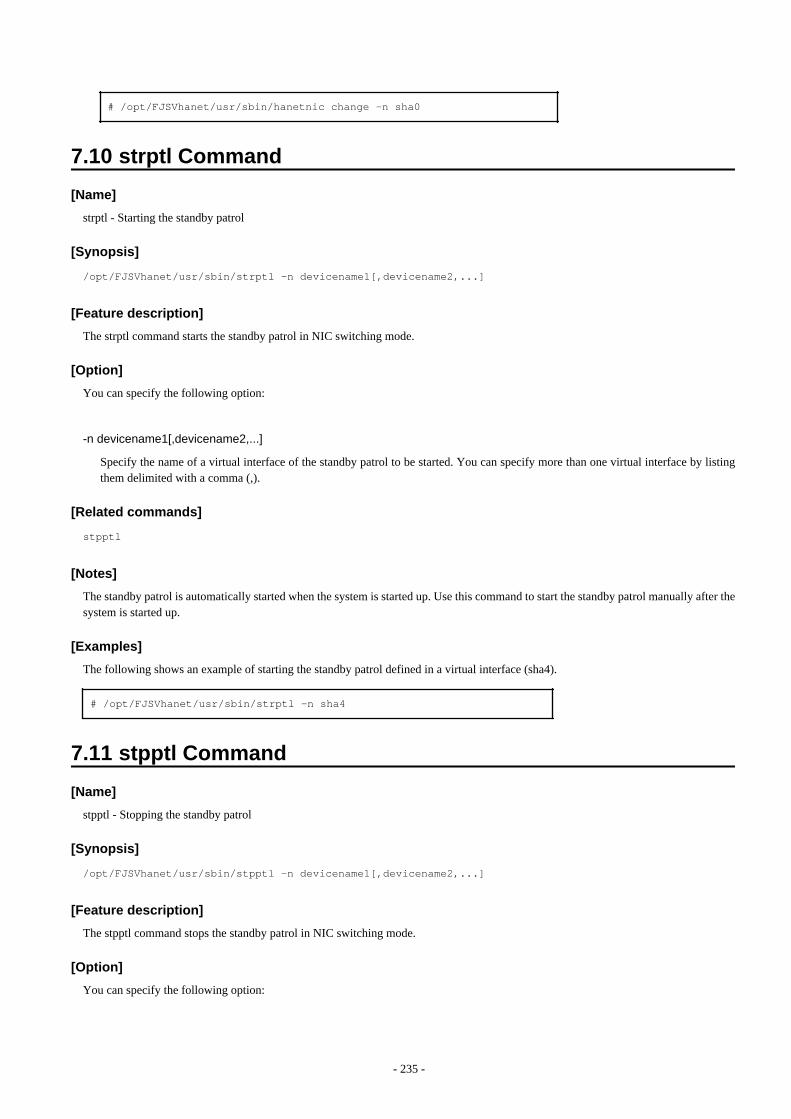
# /opt/FJSVhanet/usr/sbin/hanetnic change -n sha0
7.10 strptl Command
[Name]
strptl - Starting the standby patrol
[Synopsis]
/opt/FJSVhanet/usr/sbin/strptl -n devicename1[,devicename2,...]
[Feature description]
The strptl command starts the standby patrol in NIC switching mode.
[Option]
You can specify the following option:
-n devicename1[,devicename2,...]
Specify the name of a virtual interface of the standby patrol to be started. You can specify more than one virtual interface by listingthem delimited with a comma (,).
[Related commands]
stpptl
[Notes]
The standby patrol is automatically started when the system is started up. Use this command to start the standby patrol manually after thesystem is started up.
[Examples]
The following shows an example of starting the standby patrol defined in a virtual interface (sha4).
# /opt/FJSVhanet/usr/sbin/strptl -n sha4
7.11 stpptl Command
[Name]
stpptl - Stopping the standby patrol
[Synopsis]
/opt/FJSVhanet/usr/sbin/stpptl -n devicename1[,devicename2,...]
[Feature description]
The stpptl command stops the standby patrol in NIC switching mode.
[Option]
You can specify the following option:
- 235 -

-n devicename1[,devicename2,...]
Specify the name of a virtual interface of the standby patrol to be stopped. You can specify more than one virtual interface by listingthem delimited with a comma (,).
[Related commands]
strptl
[Notes]
The standby patrol is automatically stopped when the system is shut down. Use this command to stop the standby patrol manually afterthe system is started up.
[Examples]
The following shows an example of stopping the standby patrol defined in a virtual interface (sha4).
# /opt/FJSVhanet/usr/sbin/stpptl -n sha4
7.12 hanetbackup Command
[Name]
hanetbackup - Backing up the environment definition files
[Synopsis]
/opt/FJSVhanet/usr/sbin/hanetbackup [-d backupdir]
[Feature description]
The hanetbackup command backs up the environment definition files used by Redundant Line Control function. The backup files arenamed "hanetYYYYMMDD.bk". YYYYMMDD is the information obtained when the command is executed (YYYY, MM, and DD standsfor the year, month and day, respectively).
[Option]
You can specify the following option:
-d backupdir
Specify a directory to which backup environment definition files should be saved. If this option is omitted, the backup files will besaved to under /tmp.
[Related commands]
hanetrestore
[Notes]
If the backup command is executed more than once on the same day using the same output destination, the backup file will be overwritten.Before executing this command, save as required the file that has been output using this command.
[Examples]
The following shows an example of outputting environment definition files to under /tmp.
# /opt/FJSVhanet/usr/sbin/hanetbackup
- 236 -
7.13 hanetrestore Command
[Name]
hanetrestore - Restoring the environment definition files
[Synopsis]
/opt/FJSVhanet/usr/sbin/hanetrestore -f backupfilename
[Feature description]
The hanetrestore command restores the environment definition files used by Redundant Line Control function.
[Option]
You can specify the following options:
-f backupfilename
Specify a file created using the backup command.
[Related commands]
hanetbackup
[Notes]
- After executing this command, be sure to reboot the system.
- Do not execute this command when the environment setting is completed. If executed, there is a possibility that a conflict will occurin the definition information, which makes it not possible to work properly. In this case, delete the definition information by a resethanetcommand and set the environment again. See "7.15 resethanet Command" for the detail of a resethanet command.
- The supported environment files for restoring the environment definition files with this command are the packages (FJSVhanet) withversion 2.3 or later. The packages (FJSVhanet) prior to version 2.2 are not supported.
[Examples]
The following shows an example of restoring a file (/tmp/hanet20041129.bk) created using the backup command.
# /opt/FJSVhanet/usr/sbin/hanetrestore -f /tmp/hanet20041129.bk
7.14 hanethvrsc Command
[Name]
hanethvrsc - Sets the information of a virtual interface to register in the cluster resources.
[Synopsis]
/opt/FJSVhanet/usr/sbin/hanethvrsc command [args]
[Feature description]
hanethvrsc command makes it possible to create/delete/display the information of a virtual interface to register in the resources ofPRIMECLUSTER.
- 237 -
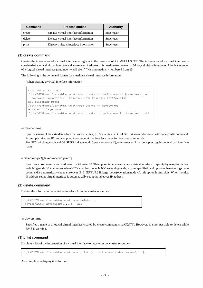
Command Process outline Authority
create Creates virtual interface information Super user
delete Deletes virtual interface information Super user
print Displays virtual interface information Super user
(1) create command
Creates the information of a virtual interface to register in the resources of PRIMECLUSTER. The information of a virtual interface isconsisted of a logical virtual interface and a takeover IP address. It is possible to create up to 64 logical virtual interfaces. A logical numberof a logical virtual interface (a number to add after ":") is automatically numbered from 65.
The following is the command format for creating a virtual interface information:
- When creating a virtual interface information
Fast switching mode:/opt/FJSVhanet/usr/sbin/hanethvrsc create -n devicename -i {takeover-ipv4 | takeover-ipv6/prefix | takeover-ipv4,takeover-ipv6/prefix}NIC switching mode:/opt/FJSVhanet/usr/sbin/hanethvrsc create -n devicenameGS/SURE linkage mode:/opt/FJSVhanet/usr/sbin/hanethvrsc create -n devicename [-i takeover-ipv4]
-n devicename:
Specify a name of the virtual interface for Fast switching, NIC switching or GS/SURE linkage mode created with hanetconfig command.A multiple takeover IP can be applied to a single virtual interface name for Fast switching mode.For NIC switching mode and GS/SURE linkage mode (operation mode 'c'), one takeover IP can be applied against one virtual interfacename.
-i takeover-ipv4[,takeover-ipv6/prefix]:
Specifies a host name or an IP address of a takeover IP. This option is necessary when a virtual interface to specify by -n option is Fastswitching mode. Not necessary when NIC switching mode. In NIC switching mode, a value specified by -i option of hanetconfig createcommand is automatically set as a takeover IP. In GS/SURE linkage mode (operation mode 'c'), this option is omissible. When it omits,IP address set as virtual interface is automatically set up as takeover IP address.
(2) delete command
Deletes the information of a virtual interface from the cluster resources.
/opt/FJSVhanet/usr/sbin/hanethvrsc delete -n {devicename1[,devicename2,...] | all}
-n devicename:
Specifies a name of a logical virtual interface created by create command (shaXX:YY). However, it is not possible to delete whileRMS is working.
(3) print command
Displays a list of the information of a virtual interface to register in the cluster resources.
/opt/FJSVhanet/usr/sbin/hanethvrsc print [-n devicename1[,devicename2,...]]
An example of a display is as follows:
- 238 -
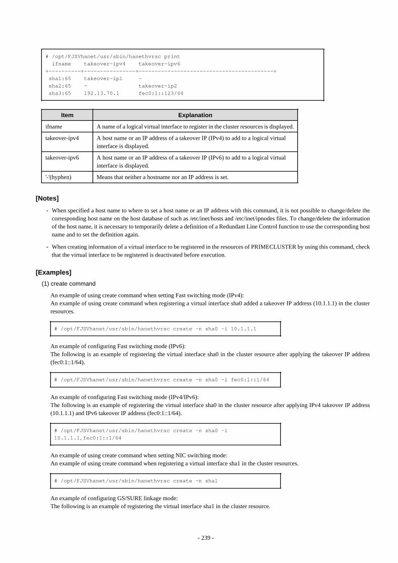
# /opt/FJSVhanet/usr/sbin/hanethvrsc print ifname takeover-ipv4 takeover-ipv6+----------+----------------+------------------------------------------+ sha1:65 takeover-ip1 - sha2:65 - takeover-ip2 sha3:65 192.13.70.1 fec0:1::123/64
Item Explanation
ifname A name of a logical virtual interface to register in the cluster resources is displayed.
takeover-ipv4 A host name or an IP address of a takeover IP (IPv4) to add to a logical virtualinterface is displayed.
takeover-ipv6 A host name or an IP address of a takeover IP (IPv6) to add to a logical virtualinterface is displayed.
'-'(hyphen) Means that neither a hostname nor an IP address is set.
[Notes]
- When specified a host name to where to set a host name or an IP address with this command, it is not possible to change/delete thecorresponding host name on the host database of such as /etc/inet/hosts and /etc/inet/ipnodes files. To change/delete the informationof the host name, it is necessary to temporarily delete a definition of a Redundant Line Control function to use the corresponding hostname and to set the definition again.
- When creating information of a virtual interface to be registered in the resources of PRIMECLUSTER by using this command, checkthat the virtual interface to be registered is deactivated before execution.
[Examples]
(1) create command
An example of using create command when setting Fast switching mode (IPv4):An example of using create command when registering a virtual interface sha0 added a takeover IP address (10.1.1.1) in the clusterresources.
# /opt/FJSVhanet/usr/sbin/hanethvrsc create -n sha0 -i 10.1.1.1
An example of configuring Fast switching mode (IPv6):The following is an example of registering the virtual interface sha0 in the cluster resource after applying the takeover IP address(fec0:1::1/64).
# /opt/FJSVhanet/usr/sbin/hanethvrsc create -n sha0 -i fec0:1::1/64
An example of configuring Fast switching mode (IPv4/IPv6):The following is an example of registering the virtual interface sha0 in the cluster resource after applying IPv4 takeover IP address(10.1.1.1) and IPv6 takeover IP address (fec0:1::1/64).
# /opt/FJSVhanet/usr/sbin/hanethvrsc create -n sha0 -i 10.1.1.1,fec0:1::1/64
An example of using create command when setting NIC switching mode:An example of using create command when registering a virtual interface sha1 in the cluster resources.
# /opt/FJSVhanet/usr/sbin/hanethvrsc create -n sha1
An example of configuring GS/SURE linkage mode:The following is an example of registering the virtual interface sha1 in the cluster resource.
- 239 -

# /opt/FJSVhanet/usr/sbin/hanethvrsc create -n sha1 -i 192.168.80.10
(2) delete command
An example of using create command when deleting a logical virtual interface sha1:65 from the cluster resources.
# /opt/FJSVhanet/usr/sbin/hanethvrsc delete -n sha1:65
(3) print command
An example of displaying a list of the information of a virtual interface to register to the cluster resources.
# /opt/FJSVhanet/usr/sbin/hanethvrsc print
7.15 resethanet Command
[Name]
resethanet - Initializes the information of virtual interface configuration and reactivates a Redundant Line Control function.
[Synopsis]
/opt/FJSVhanet/usr/sbin/resethanet -i | -s
[Feature description]
resethanet commands initializes the information of virtual interface configuration and reactivates a Redundant Line Control function. Theinitialized configuration information is as follows.
- The information of virtual interface configuration (the definition information set by hanetconfig command)
- The monitor-to information (the definition information set by hanetpoll command)
The parameters set by hanetpoll on command, hanetparam command, and hanetobserv command are not initialized.
[Option]
Specify the following options:
-i:
Specify to initialize the information of virtual interface configuration. Do not specify this option except to stop using a Redundant LineControl function during the operation, or to recreate the information of virtual interface configuration.
-s:
Specify to reactivate a Redundant Line Control function. This option validates changed content of the setting without rebooting asystem when changed the information of virtual interface configuration.
(1) Initializing the configuration information
Initialize the configuration information of a virtual interface.
# /opt/FJSVhanet/usr/sbin/resethanet -i
- 240 -
-i:
Initializes the configuration information of a virtual interface and makes it the status of no definition. However, if even one virtualinterface is registered as cluster resources in the corresponding system, it is not possible to initialize.
(2) Reactivating a Redundant Line Control function
Reactivates a Redundant Line Control function.
# /opt/FJSVhanet/usr/sbin/resethanet -s
-s:
Reactivates a Redundant Line Control function. However, if RMS is activated at PRIMECLUSTER operation in a correspondingsystem, it is not possible to reactivate.
[Notes]
- When the configuration information is initialized with the command, it cannot be returned to the original state prior to initialization.Users are recommended to save the information using the hanetbackup command.
- If the shared-IP non-global of the Solaris Zones is using the virtual interface, stop the Solaris Zones then change the network settingbefore initializing the virtual interface configuration.
- When you execute this command, please stop RMS beforehand.
[Examples]
The following is an example of initialize the configuration information of a virtual interface.
# /opt/FJSVhanet/usr/sbin/resethanet -i
The following is an example of reactivates a Redundant Line Control Function.
# /opt/FJSVhanet/usr/sbin/resethanet -s
7.16 hanetgw Command
[Name]
hanetgw - Setting, deleting, and displaying a virtual gateway configuration definition of GS/SURE linkage mode.
[Synopsis]
/opt/FJSVhanet/usr/sbin/hanetgw command [args]
[Feature description]
The hanetgw command creates/deletes/displays the virtual gateway required for operating in GS/SURE linkage mode. The virtual gatewayis used to communicate in GS/SURE linkage mode. By creating the virtual gateway, the virtual IP address is automatically selected as thelocal IP address which is used for communication. Moreover, the host route through the virtual gateway for the communication target isautomatically registered when a virtual interface is activated.
Command Process outline Authority
create Creates configuration information Super user
delete Deletes configuration information Super user
print Displays configuration information General user
- 241 -

(1) create command
Set the virtual gateway address for the virtual interface in GS/SURE linkage mode.The command format for setting the virtual gateway is as follows.
/opt/FJSVhanet/usr/sbin/hanetgw create -n devicename -g gwaddr
-n devicename
Specify the virtual interface in GS/SURE linkage mode.
-g gwaddr
Specify the host name or IP address for the virtual gateway information. This host name or IP address should be associated with an IPaddress in a network database including the /etc/hosts file.
(2) delete command
Use the delete command to delete the virtual gateway information. The command format is as follows.
/opt/FJSVhanet/usr/sbin/hanetgw delete -n {devicename1[,devicename2,...] | all}
-n devicename1[,devicename2,...]
Specify the name of the virtual interface whose information you want to delete.
-n all
Delete all the defined virtual gateway information.
(3) print command
Displays the contents of the settings for the virtual gateway information. The command format for displaying the virtual gatewayinformation is as follows.
/opt/FJSVhanet/usr/sbin/hanetgw print [-n devicename1[,devicename2,...]]
Shown below is an example of the displayed virtual gateway information.
# /opt/FJSVhanet/usr/sbin/hanetgw print ifname GW Address+------+----------------+ sha0 192.168.80.254 sha10 192.168.90.254
Display Contents
ifname Virtual interface on which the virtual gateway is set
GW Address Host name or IP address set for the virtual gateway
- 242 -
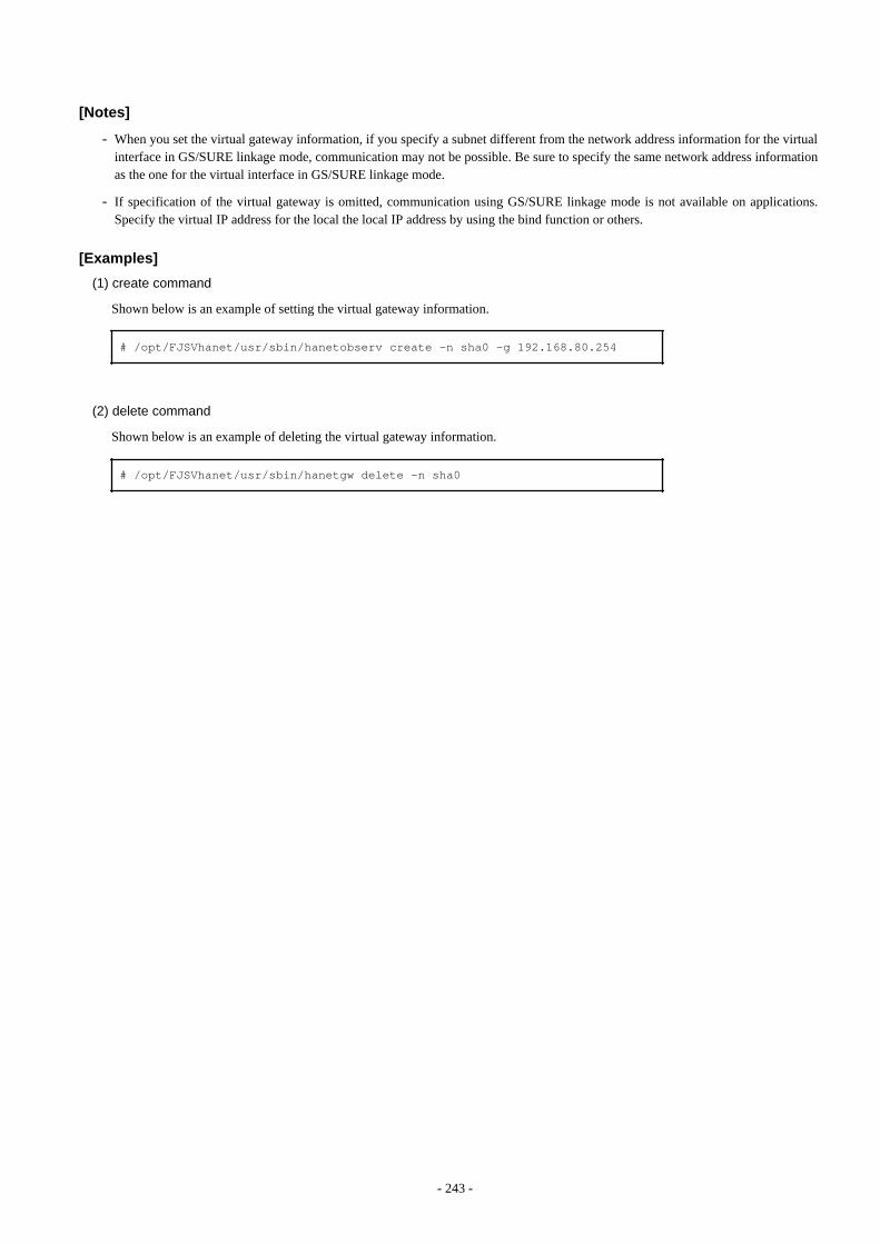
[Notes]
- When you set the virtual gateway information, if you specify a subnet different from the network address information for the virtualinterface in GS/SURE linkage mode, communication may not be possible. Be sure to specify the same network address informationas the one for the virtual interface in GS/SURE linkage mode.
- If specification of the virtual gateway is omitted, communication using GS/SURE linkage mode is not available on applications.Specify the virtual IP address for the local the local IP address by using the bind function or others.
[Examples]
(1) create command
Shown below is an example of setting the virtual gateway information.
# /opt/FJSVhanet/usr/sbin/hanetobserv create -n sha0 -g 192.168.80.254
(2) delete command
Shown below is an example of deleting the virtual gateway information.
# /opt/FJSVhanet/usr/sbin/hanetgw delete -n sha0
- 243 -
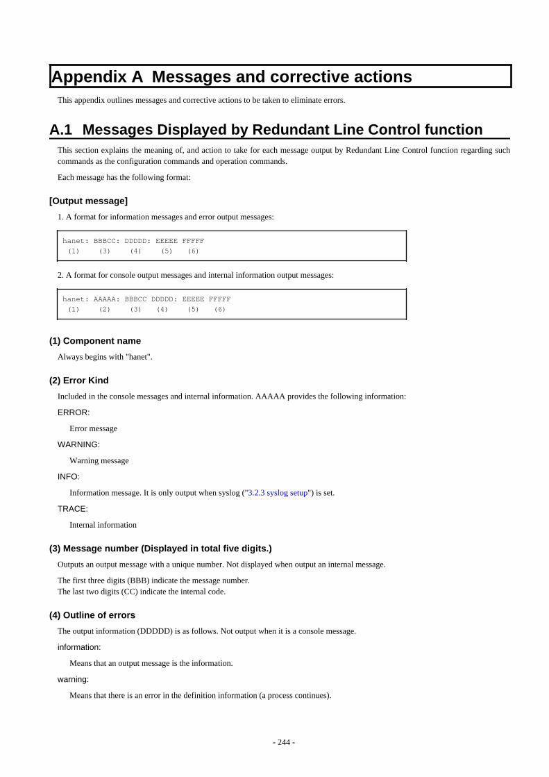
Appendix A Messages and corrective actionsThis appendix outlines messages and corrective actions to be taken to eliminate errors.
A.1 Messages Displayed by Redundant Line Control functionThis section explains the meaning of, and action to take for each message output by Redundant Line Control function regarding suchcommands as the configuration commands and operation commands.
Each message has the following format:
[Output message]
1. A format for information messages and error output messages:
hanet: BBBCC: DDDDD: EEEEE FFFFF (1) (3) (4) (5) (6)
2. A format for console output messages and internal information output messages:
hanet: AAAAA: BBBCC DDDDD: EEEEE FFFFF (1) (2) (3) (4) (5) (6)
(1) Component name
Always begins with "hanet".
(2) Error Kind
Included in the console messages and internal information. AAAAA provides the following information:
ERROR:
Error message
WARNING:
Warning message
INFO:
Information message. It is only output when syslog ("3.2.3 syslog setup") is set.
TRACE:
Internal information
(3) Message number (Displayed in total five digits.)
Outputs an output message with a unique number. Not displayed when output an internal message.
The first three digits (BBB) indicate the message number.The last two digits (CC) indicate the internal code.
(4) Outline of errors
The output information (DDDDD) is as follows. Not output when it is a console message.
information:
Means that an output message is the information.
warning:
Means that there is an error in the definition information (a process continues).
- 244 -
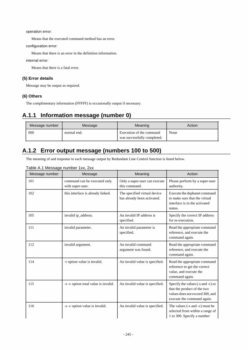
operation error:
Means that the executed command method has an error.
configuration error:
Means that there is an error in the definition information.
internal error:
Means that there is a fatal error.
(5) Error details
Message may be output as required.
(6) Others
The complimentary information (FFFFF) is occasionally output if necessary.
A.1.1 Information message (number 0)
Message number Message Meaning Action
000 normal end. Execution of the commandwas successfully completed.
None
A.1.2 Error output message (numbers 100 to 500)The meaning of and response to each message output by Redundant Line Control function is listed below.
Table A.1 Message number 1xx, 2xx
Message number Message Meaning Action
101 command can be executed onlywith super-user.
Only a super-user can executethis command.
Please perform by a super-userauthority.
102 this interface is already linked. The specified virtual devicehas already been activated.
Execute the dsphanet commandto make sure that the virtualinterface is in the activatedstatus.
105 invalid ip_address. An invalid IP address isspecified.
Specify the correct IP addressfor re-execution.
111 invalid parameter. An invalid parameter isspecified.
Read the appropriate commandreference, and execute thecommand again.
112 invalid argument. An invalid commandargument was found.
Read the appropriate commandreference, and execute thecommand again.
114 -r option value is invalid. An invalid value is specified. Read the appropriate commandreference to get the correctvalue, and execute thecommand again.
115 -s -c option total value is invalid. An invalid value is specified. Specify the values (-s and -c) sothat the product of the twovalues does not exceed 300, andexecute the command again.
116 -s -c option value is invalid. An invalid value is specified. The values (-s and -c) must beselected from within a range of1 to 300. Specify a number
- 245 -
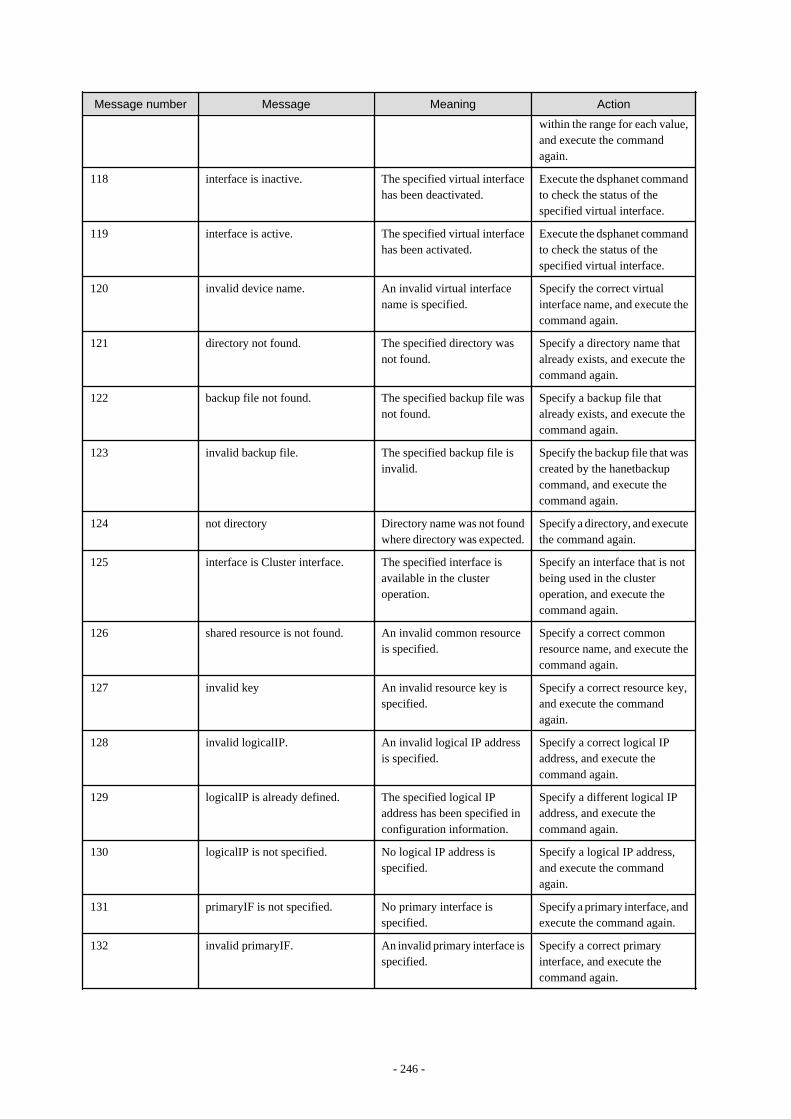
Message number Message Meaning Action
within the range for each value,and execute the commandagain.
118 interface is inactive. The specified virtual interfacehas been deactivated.
Execute the dsphanet commandto check the status of thespecified virtual interface.
119 interface is active. The specified virtual interfacehas been activated.
Execute the dsphanet commandto check the status of thespecified virtual interface.
120 invalid device name. An invalid virtual interfacename is specified.
Specify the correct virtualinterface name, and execute thecommand again.
121 directory not found. The specified directory wasnot found.
Specify a directory name thatalready exists, and execute thecommand again.
122 backup file not found. The specified backup file wasnot found.
Specify a backup file thatalready exists, and execute thecommand again.
123 invalid backup file. The specified backup file isinvalid.
Specify the backup file that wascreated by the hanetbackupcommand, and execute thecommand again.
124 not directory Directory name was not foundwhere directory was expected.
Specify a directory, and executethe command again.
125 interface is Cluster interface. The specified interface isavailable in the clusteroperation.
Specify an interface that is notbeing used in the clusteroperation, and execute thecommand again.
126 shared resource is not found. An invalid common resourceis specified.
Specify a correct commonresource name, and execute thecommand again.
127 invalid key An invalid resource key isspecified.
Specify a correct resource key,and execute the commandagain.
128 invalid logicalIP. An invalid logical IP addressis specified.
Specify a correct logical IPaddress, and execute thecommand again.
129 logicalIP is already defined. The specified logical IPaddress has been specified inconfiguration information.
Specify a different logical IPaddress, and execute thecommand again.
130 logicalIP is not specified. No logical IP address isspecified.
Specify a logical IP address,and execute the commandagain.
131 primaryIF is not specified. No primary interface isspecified.
Specify a primary interface, andexecute the command again.
132 invalid primaryIF. An invalid primary interface isspecified.
Specify a correct primaryinterface, and execute thecommand again.
- 246 -
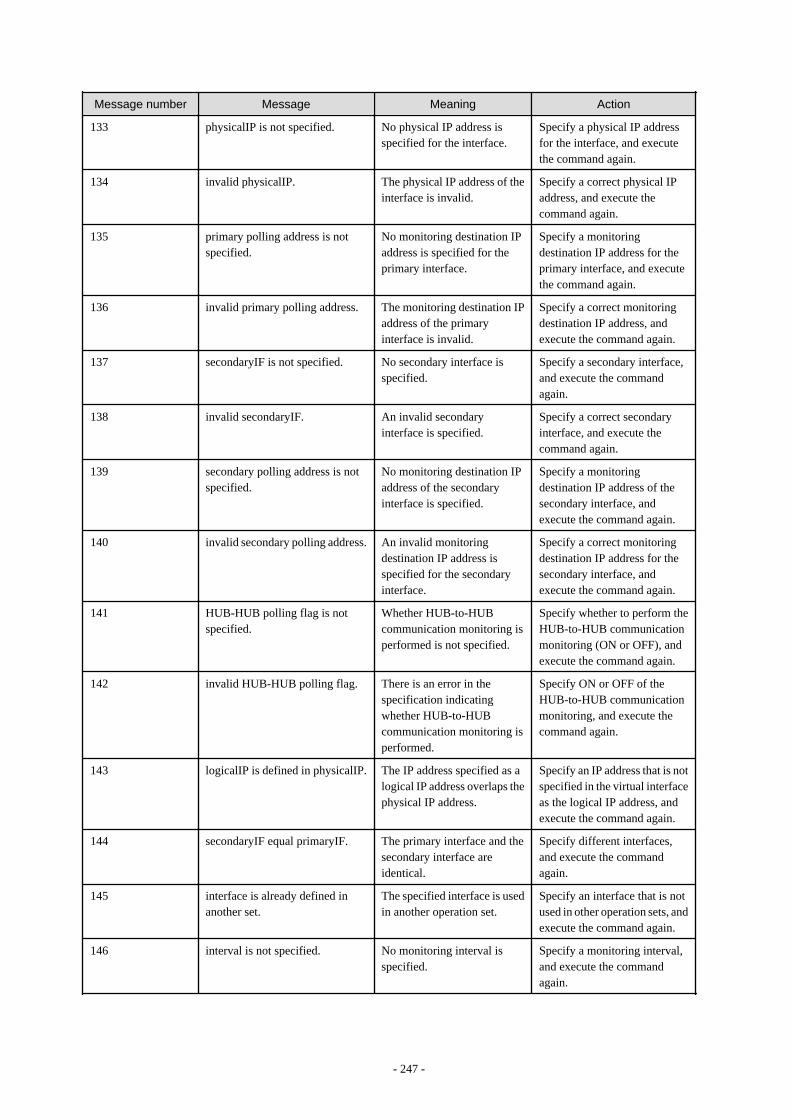
Message number Message Meaning Action
133 physicalIP is not specified. No physical IP address isspecified for the interface.
Specify a physical IP addressfor the interface, and executethe command again.
134 invalid physicalIP. The physical IP address of theinterface is invalid.
Specify a correct physical IPaddress, and execute thecommand again.
135 primary polling address is notspecified.
No monitoring destination IPaddress is specified for theprimary interface.
Specify a monitoringdestination IP address for theprimary interface, and executethe command again.
136 invalid primary polling address. The monitoring destination IPaddress of the primaryinterface is invalid.
Specify a correct monitoringdestination IP address, andexecute the command again.
137 secondaryIF is not specified. No secondary interface isspecified.
Specify a secondary interface,and execute the commandagain.
138 invalid secondaryIF. An invalid secondaryinterface is specified.
Specify a correct secondaryinterface, and execute thecommand again.
139 secondary polling address is notspecified.
No monitoring destination IPaddress of the secondaryinterface is specified.
Specify a monitoringdestination IP address of thesecondary interface, andexecute the command again.
140 invalid secondary polling address. An invalid monitoringdestination IP address isspecified for the secondaryinterface.
Specify a correct monitoringdestination IP address for thesecondary interface, andexecute the command again.
141 HUB-HUB polling flag is notspecified.
Whether HUB-to-HUBcommunication monitoring isperformed is not specified.
Specify whether to perform theHUB-to-HUB communicationmonitoring (ON or OFF), andexecute the command again.
142 invalid HUB-HUB polling flag. There is an error in thespecification indicatingwhether HUB-to-HUBcommunication monitoring isperformed.
Specify ON or OFF of theHUB-to-HUB communicationmonitoring, and execute thecommand again.
143 logicalIP is defined in physicalIP. The IP address specified as alogical IP address overlaps thephysical IP address.
Specify an IP address that is notspecified in the virtual interfaceas the logical IP address, andexecute the command again.
144 secondaryIF equal primaryIF. The primary interface and thesecondary interface areidentical.
Specify different interfaces,and execute the commandagain.
145 interface is already defined inanother set.
The specified interface is usedin another operation set.
Specify an interface that is notused in other operation sets, andexecute the command again.
146 interval is not specified. No monitoring interval isspecified.
Specify a monitoring interval,and execute the commandagain.
- 247 -
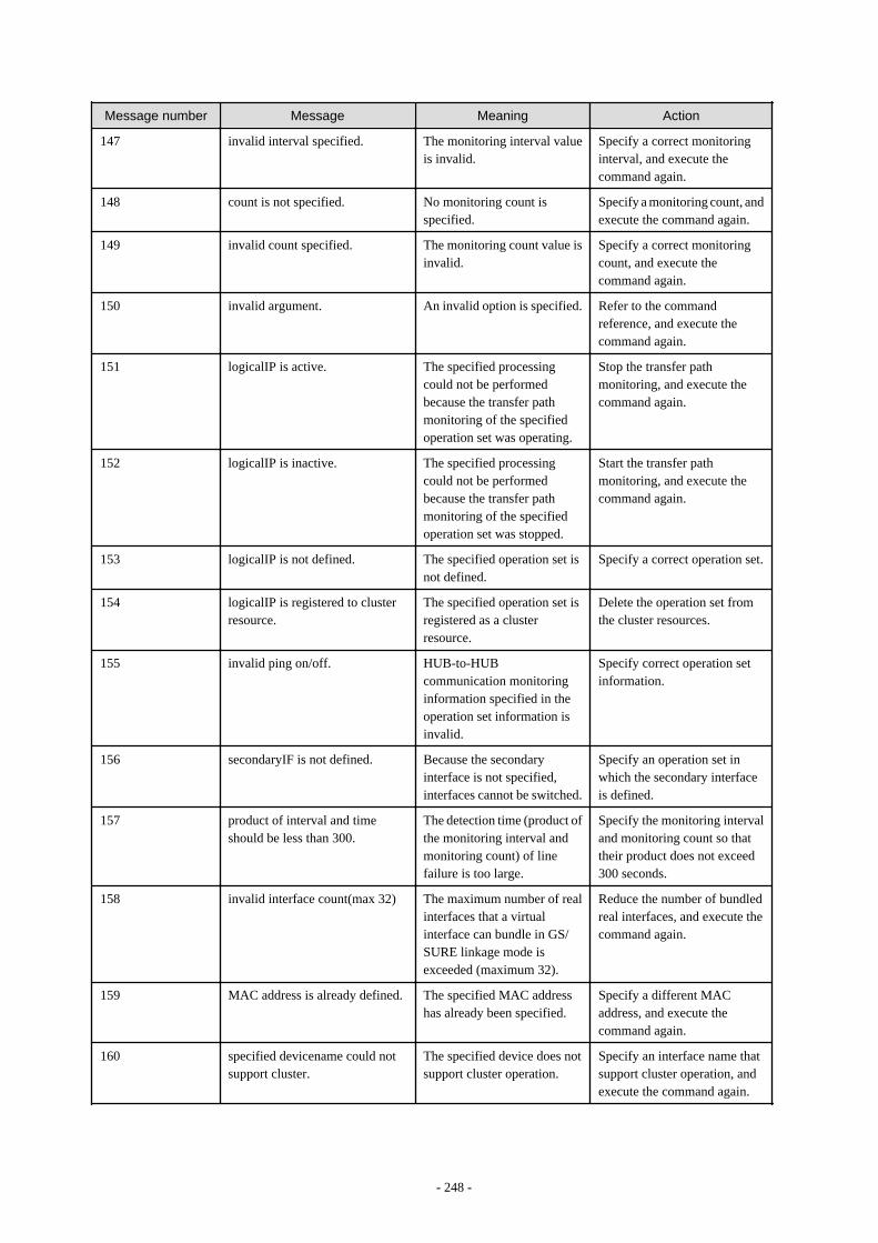
Message number Message Meaning Action
147 invalid interval specified. The monitoring interval valueis invalid.
Specify a correct monitoringinterval, and execute thecommand again.
148 count is not specified. No monitoring count isspecified.
Specify a monitoring count, andexecute the command again.
149 invalid count specified. The monitoring count value isinvalid.
Specify a correct monitoringcount, and execute thecommand again.
150 invalid argument. An invalid option is specified. Refer to the commandreference, and execute thecommand again.
151 logicalIP is active. The specified processingcould not be performedbecause the transfer pathmonitoring of the specifiedoperation set was operating.
Stop the transfer pathmonitoring, and execute thecommand again.
152 logicalIP is inactive. The specified processingcould not be performedbecause the transfer pathmonitoring of the specifiedoperation set was stopped.
Start the transfer pathmonitoring, and execute thecommand again.
153 logicalIP is not defined. The specified operation set isnot defined.
Specify a correct operation set.
154 logicalIP is registered to clusterresource.
The specified operation set isregistered as a clusterresource.
Delete the operation set fromthe cluster resources.
155 invalid ping on/off. HUB-to-HUBcommunication monitoringinformation specified in theoperation set information isinvalid.
Specify correct operation setinformation.
156 secondaryIF is not defined. Because the secondaryinterface is not specified,interfaces cannot be switched.
Specify an operation set inwhich the secondary interfaceis defined.
157 product of interval and timeshould be less than 300.
The detection time (product ofthe monitoring interval andmonitoring count) of linefailure is too large.
Specify the monitoring intervaland monitoring count so thattheir product does not exceed300 seconds.
158 invalid interface count(max 32) The maximum number of realinterfaces that a virtualinterface can bundle in GS/SURE linkage mode isexceeded (maximum 32).
Reduce the number of bundledreal interfaces, and execute thecommand again.
159 MAC address is already defined. The specified MAC addresshas already been specified.
Specify a different MACaddress, and execute thecommand again.
160 specified devicename could notsupport cluster.
The specified device does notsupport cluster operation.
Specify an interface name thatsupport cluster operation, andexecute the command again.
- 248 -
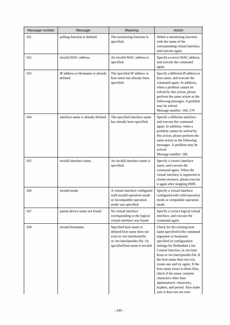
Message number Message Meaning Action
161 polling function is defined. The monitoring function isspecified.
Delete a monitoring functionwith the name of thecorresponding virtual interface,and execute again.
162 invalid MAC address. An invalid MAC address isspecified.
Specify a correct MAC address,and execute the commandagain.
163 IP address or Hostname is alreadydefined.
The specified IP address orhost name has already beenspecified.
Specify a different IP address orhost name, and execute thecommand again. In addition,when a problem cannot besolved by this action, pleaseperform the same action as thefollowing messages. A problemmay be solved.Message number: 169, 170
164 interface name is already defined. The specified interface namehas already been specified.
Specify a different interface,and execute the commandagain. In addition, when aproblem cannot be solved bythis action, please perform thesame action as the followingmessages. A problem may besolved.Message number: 166
165 invalid interface name. An invalid interface name isspecified.
Specify a correct interfacename, and execute thecommand again. When thevirtual interface is registered incluster resource, please executeit again after stopping RMS.
166 invalid mode. A virtual interface configuredwith invalid operation modeor incompatible operationmode was specified.
Specify a virtual interfaceconfigured with valid operationmode or compatible operationmode.
167 parent device name not found. No virtual interfacecorresponding to the logicalvirtual interface was found.
Specify a correct logical virtualinterface, and execute thecommand again.
168 invalid hostname. Specified host name ordefined host name does notexist in /etc/inet/hostsfileor /etc/inet/ipnodes file. Or,specified host name is invalid.
Check for the existing hostname specified in the commandargument or hostnamespecified in configurationsettings for Redundant LineControl function, in /etc/inet/hosts or /etc/inet/ipnodes file. Ifthe host name does not exit,create one and try again. If thehost name exists in these files,check if the name containscharacters other thanalphanumeric characters,hyphen, and period. Also makesure it does not use non-
- 249 -

Message number Message Meaning Action
alphanumeric characters for thefirst and last character. If itcontains these characters,change the name and re-executethe command.
169 physical interface name is alreadydefined.
The specified physicalinterface name has alreadybeen specified.
Specify a different physicalinterface name, and execute thecommand again. This messagemay also be output if thespecified physical interface isshared with another virtualinterface when changing theconfiguration definition. In thiscase, delete another virtualinterface in advance, or specifyanother physical interface thatis not shared with anothervirtual interface. In addition,when a problem cannot besolved by this action, pleaseperform the same action as thefollowing messages. A problemmay be solved.Message number: 166
170 invalid physical interface name. An invalid physical interfacename is specified.
Specify the correct name of thephysical interface (the name ofthe virtual interface when themode is "p" or "q"), and executeagain. When setting a standbypatrol function, check that twophysical interfaces are definedthat configure a virtualinterface to be monitored. Inaddition, when a problemcannot be solved by this action,please perform the same actionas the following messages. Aproblem may be solved.Message number: 164
171 trunking interface list is notspecified.
No interface that operates intrunking mode is specified.
Specify an interface, andexecute the command again.
172 mode p interface is defined. A virtual interface in mode Pis specified.
Delete the interface in mode P,and execute the commandagain.
173 mode c interface is activated. An interface in mode C isactivated.
Inactivate the interface in modeC, and execute the commandagain.
174 ifname is not defined inhanetconfig.
The specified virtual interfacename is not specified inconfiguration information.
Create configurationinformation using thehanetconfig command, andexecute the command again.
- 250 -
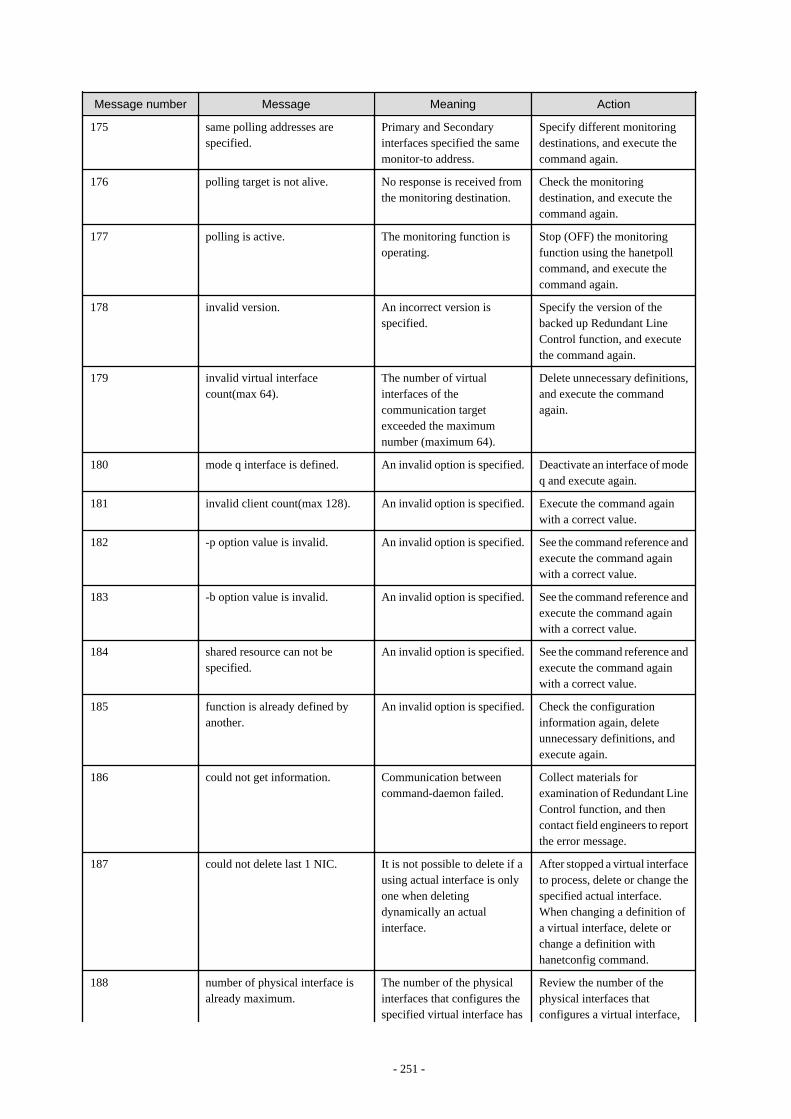
Message number Message Meaning Action
175 same polling addresses arespecified.
Primary and Secondaryinterfaces specified the samemonitor-to address.
Specify different monitoringdestinations, and execute thecommand again.
176 polling target is not alive. No response is received fromthe monitoring destination.
Check the monitoringdestination, and execute thecommand again.
177 polling is active. The monitoring function isoperating.
Stop (OFF) the monitoringfunction using the hanetpollcommand, and execute thecommand again.
178 invalid version. An incorrect version isspecified.
Specify the version of thebacked up Redundant LineControl function, and executethe command again.
179 invalid virtual interfacecount(max 64).
The number of virtualinterfaces of thecommunication targetexceeded the maximumnumber (maximum 64).
Delete unnecessary definitions,and execute the commandagain.
180 mode q interface is defined. An invalid option is specified. Deactivate an interface of modeq and execute again.
181 invalid client count(max 128). An invalid option is specified. Execute the command againwith a correct value.
182 -p option value is invalid. An invalid option is specified. See the command reference andexecute the command againwith a correct value.
183 -b option value is invalid. An invalid option is specified. See the command reference andexecute the command againwith a correct value.
184 shared resource can not bespecified.
An invalid option is specified. See the command reference andexecute the command againwith a correct value.
185 function is already defined byanother.
An invalid option is specified. Check the configurationinformation again, deleteunnecessary definitions, andexecute again.
186 could not get information. Communication betweencommand-daemon failed.
Collect materials forexamination of Redundant LineControl function, and thencontact field engineers to reportthe error message.
187 could not delete last 1 NIC. It is not possible to delete if ausing actual interface is onlyone when deletingdynamically an actualinterface.
After stopped a virtual interfaceto process, delete or change thespecified actual interface.When changing a definition ofa virtual interface, delete orchange a definition withhanetconfig command.
188 number of physical interface isalready maximum.
The number of the physicalinterfaces that configures thespecified virtual interface has
Review the number of thephysical interfaces thatconfigures a virtual interface,
- 251 -
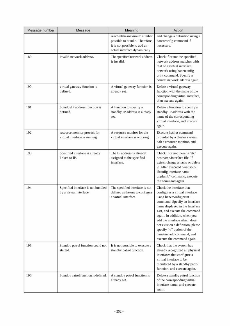
Message number Message Meaning Action
reached the maximum numberpossible to bundle. Therefore,it is not possible to add anactual interface dynamically.
and change a definition using ahanetconfig command ifnecessary.
189 invalid network address. The specified network addressis invalid.
Check if or not the specifiednetwork address matches withthat of a virtual interfacenetwork using hanetconfigprint command. Specify acorrect network address again.
190 virtual gateway function isdefined.
A virtual gateway function isalready set.
Delete a virtual gatewayfunction with the name of thecorresponding virtual interface,then execute again.
191 StandbyIP address function isdefined.
A function to specify astandby IP address is alreadyset.
Delete a function to specify astandby IP address with thename of the correspondingvirtual interface, and executeagain.
192 resource monitor process forvirtual interface is running.
A resource monitor for thevirtual interface is working.
Execute hvshut commandprovided by a cluster system,halt a resource monitor, andexecute again.
193 Specified interface is alreadylinked to IP.
The IP address is alreadyassigned to the specifiedinterface.
Check if or not there is /etc/hostname.interface file. Ifexists, change a name or deleteit. After executed "/usr/sbin/ifconfig interface nameunplumb" command, executethe command again.
194 Specified interface is not bundledby a virtual interface.
The specified interface is notdefined as the one to configurea virtual interface.
Check the interface thatconfigures a virtual interfaceusing hanetconfig printcommand. Specify an interfacename displayed in the InterfaceList, and execute the commandagain. In addition, when youadd the interface which doesnot exist on a definition, pleasespecify "-f" option of thehanetnic add command, andexecute the command again.
195 Standby patrol function could notstarted.
It is not possible to execute astandby patrol function.
Check that the system hasalready recognized all physicalinterfaces that configure avirtual interface to bemonitored by a standby patrolfunction, and execute again.
196 Standby patrol function is defined. A standby patrol function isalready set.
Delete a standby patrol functionof the corresponding virtualinterface name, and executeagain.
- 252 -

Message number Message Meaning Action
197 specified physical interface isalready unlinked.
Activation of the specifiedphysical interface is alreadydeleted.
Using dsphanet command,check that the specifiedphysical interface is not usedyet.
198 address family of takeover IPaddress incompatible.
The specified address form ofa takeover IP address (anaddress family) is notcompatible with that of asetting virtual interface.
Make an address form of atakeover IP address compatiblewith that of a setting virtualinterface and execute again.
199 invalid takeover IP address. The specified takeover IPaddress is invalid.
Check a value of the specifiedtakeover IP address and executeagain.
200 invalid hostname or prefix value. The specified host name orprefix value is invalid.
Check the specified host nameor prefix value and executeagain.
201 dual stack interface can not bespecified.
It is not possible to specify avirtual interface of dual stackconfiguration.
Delete a definition of thecorresponding virtual interfaceand define newly.
202 address family of polling IPaddress incompatible.
The specified address form ofa monitor-to IP address (anaddress family) is notcompatible with that of asetting virtual interface.
Make an address form of amonitor-to IP addresscompatible with that of a settingvirtual interface and executeagain.
203 interfaces defined as clusterresources still exist.
One or more virtual interfacesregistered as cluster resourcesexist.
Delete the cluster resources andexecute the command again.
204 interface defined as clusterresource is still active.
A virtual interface is active ascluster resources.
Stop RMS and execute again.
205 mode can't be changed for dualstack interface.
Mode can't be changed if thevirtual IF is a dual stack.
Temporary delete theconfiguration information ofthe virtual interface andreconfigure.
206 mode can't be changed for IPv6interface.
Mode cannot be changed if thevirtual IF is IPv6.
Temporary delete theconfiguration information ofthe virtual interface andreconfigure.
207 order of physical interface isdifferent or invalid physicalinterface name.
Order of the interfaces isincorrect or the name of theinterface is invalid.
Check the contents of theinterface and retry.
208 configuration is not defined. Valid configurationinformation or monitoringtarget's information is notconfigured.
Configure the validconfiguration information ormonitoring target'sinformation.
209 specified address family is notdefined.
The specified address type(address family) of the virtualinterface is undefined.
Ensure the specified addressmatches the address format ofconfigured virtual interface.
210 invalid address family. The specified address type(address family) does notmatch the address type of thevirtual interface.
Ensure the specified addressmatches the address format ofconfigured virtual interface.
- 253 -
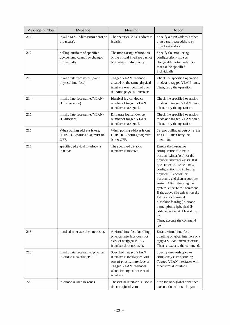
Message number Message Meaning Action
211 invalid MAC address(multicast orbroadcast).
The specified MAC address isinvalid.
Specify a MAC address otherthan a multicast address orbroadcast address.
212 polling attribute of specifieddevicename cannot be changedindividually.
The monitoring informationof the virtual interface cannotbe changed individually.
Specify the monitoringconfiguration value aschangeable virtual interfacethat can be specifiedindividually.
213 invalid interface name.(samephysical interface)
Tagged VLAN interfacecreated on the same physicalinterface was specified overthe same physical interface.
Check the specified operationmode and tagged VLAN name.Then, retry the operation.
214 invalid interface name.(VLAN-ID is the same)
Identical logical devicenumber of tagged VLANinterface is assigned.
Check the specified operationmode and tagged VLAN name.Then, retry the operation.
215 invalid interface name.(VLAN-ID different)
Disparate logical devicenumber of tagged VLANinterface is assigned.
Check the specified operationmode and tagged VLAN name.Then, retry the operation.
216 When polling address is one,HUB-HUB polling flag must beOFF.
When polling address is one,HUB-HUB polling flag mustbe set OFF.
Set two polling targets or set theflag OFF, then retry theoperation.
217 specified physical interface isinactive.
The specified physicalinterface is inactive.
Ensure the hostnameconfiguration file (/etc/hostname.interface) for thephysical interface exists. If itdoes no exist, create a newconfiguration file includingphysical IP address orhostname and then reboot thesystem After rebooting thesystem, execute the command.If the above file exists, run thefollowing command:/usr/sbin/ifconfig [interfacename] plumb [physical IPaddress] netmask + broadcast +upThen, execute the commandagain.
218 bundled interface does not exist. A virtual interface bundlingphysical interface does notexist or a tagged VLANinterface does not exist.
Ensure virtual interfacebundling physical interface or atagged VLAN interface exists.Then re-execute the command.
219 invalid interface name.(physicalinterface is overlapped)
Specified Tagged VLANinterface is overlapped withpart of physical interface orTagged VLAN interfaceswhich belongs other virtualinterface.
Specify un-overlapped orcompletely correspondingTagged VLAN interfaces withother virtual interface.
220 interface is used in zones. The virtual interface is used inthe non-global zone.
Stop the non-global zone thenexecute the command again.
- 254 -
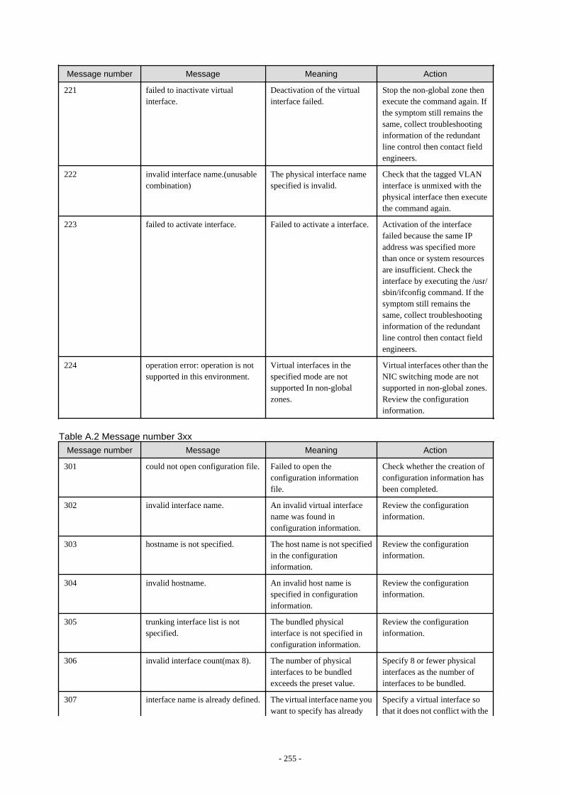
Message number Message Meaning Action
221 failed to inactivate virtualinterface.
Deactivation of the virtualinterface failed.
Stop the non-global zone thenexecute the command again. Ifthe symptom still remains thesame, collect troubleshootinginformation of the redundantline control then contact fieldengineers.
222 invalid interface name.(unusablecombination)
The physical interface namespecified is invalid.
Check that the tagged VLANinterface is unmixed with thephysical interface then executethe command again.
223 failed to activate interface. Failed to activate a interface. Activation of the interfacefailed because the same IPaddress was specified morethan once or system resourcesare insufficient. Check theinterface by executing the /usr/sbin/ifconfig command. If thesymptom still remains thesame, collect troubleshootinginformation of the redundantline control then contact fieldengineers.
224 operation error: operation is notsupported in this environment.
Virtual interfaces in thespecified mode are notsupported In non-globalzones.
Virtual interfaces other than theNIC switching mode are notsupported in non-global zones.Review the configurationinformation.
Table A.2 Message number 3xx
Message number Message Meaning Action
301 could not open configuration file. Failed to open theconfiguration informationfile.
Check whether the creation ofconfiguration information hasbeen completed.
302 invalid interface name. An invalid virtual interfacename was found inconfiguration information.
Review the configurationinformation.
303 hostname is not specified. The host name is not specifiedin the configurationinformation.
Review the configurationinformation.
304 invalid hostname. An invalid host name isspecified in configurationinformation.
Review the configurationinformation.
305 trunking interface list is notspecified.
The bundled physicalinterface is not specified inconfiguration information.
Review the configurationinformation.
306 invalid interface count(max 8). The number of physicalinterfaces to be bundledexceeds the preset value.
Specify 8 or fewer physicalinterfaces as the number ofinterfaces to be bundled.
307 interface name is already defined. The virtual interface name youwant to specify has already
Specify a virtual interface sothat it does not conflict with the
- 255 -
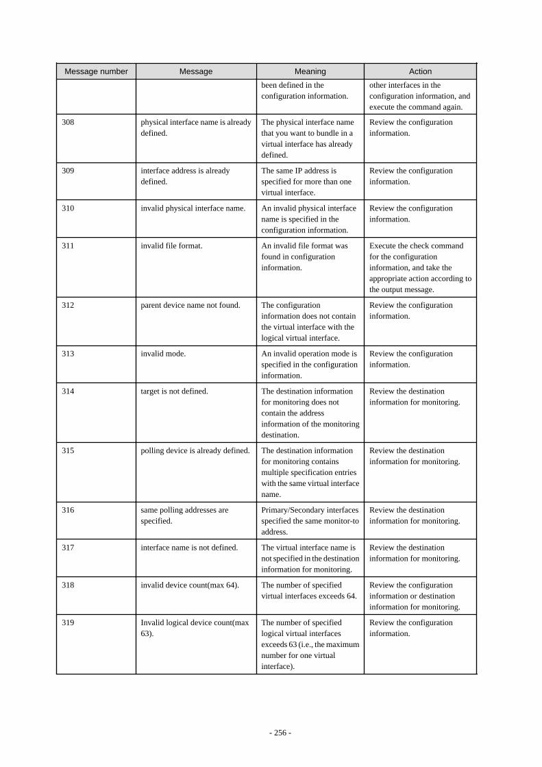
Message number Message Meaning Action
been defined in theconfiguration information.
other interfaces in theconfiguration information, andexecute the command again.
308 physical interface name is alreadydefined.
The physical interface namethat you want to bundle in avirtual interface has alreadydefined.
Review the configurationinformation.
309 interface address is alreadydefined.
The same IP address isspecified for more than onevirtual interface.
Review the configurationinformation.
310 invalid physical interface name. An invalid physical interfacename is specified in theconfiguration information.
Review the configurationinformation.
311 invalid file format. An invalid file format wasfound in configurationinformation.
Execute the check commandfor the configurationinformation, and take theappropriate action according tothe output message.
312 parent device name not found. The configurationinformation does not containthe virtual interface with thelogical virtual interface.
Review the configurationinformation.
313 invalid mode. An invalid operation mode isspecified in the configurationinformation.
Review the configurationinformation.
314 target is not defined. The destination informationfor monitoring does notcontain the addressinformation of the monitoringdestination.
Review the destinationinformation for monitoring.
315 polling device is already defined. The destination informationfor monitoring containsmultiple specification entrieswith the same virtual interfacename.
Review the destinationinformation for monitoring.
316 same polling addresses arespecified.
Primary/Secondary interfacesspecified the same monitor-toaddress.
Review the destinationinformation for monitoring.
317 interface name is not defined. The virtual interface name isnot specified in the destinationinformation for monitoring.
Review the destinationinformation for monitoring.
318 invalid device count(max 64). The number of specifiedvirtual interfaces exceeds 64.
Review the configurationinformation or destinationinformation for monitoring.
319 Invalid logical device count(max63).
The number of specifiedlogical virtual interfacesexceeds 63 (i.e., the maximumnumber for one virtualinterface).
Review the configurationinformation.
- 256 -
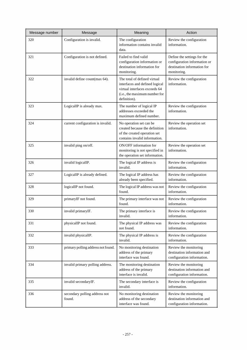
Message number Message Meaning Action
320 Configuration is invalid. The configurationinformation contains invaliddata.
Review the configurationinformation.
321 Configuration is not defined. Failed to find validconfiguration information ordestination information formonitoring.
Define the settings for theconfiguration information ordestination information formonitoring.
322 invalid define count(max 64). The total of defined virtualinterfaces and defined logicalvirtual interfaces exceeds 64(i.e., the maximum number fordefinition).
Review the configurationinformation.
323 LogicalIP is already max. The number of logical IPaddresses exceeded themaximum defined number.
Review the configurationinformation.
324 current configuration is invalid. No operation set can becreated because the definitionof the created operation setcontains invalid information.
Review the operation setinformation.
325 invalid ping on/off. ON/OFF information formonitoring is not specified inthe operation set information.
Review the operation setinformation.
326 invalid logicalIP. The logical IP address isinvalid.
Review the configurationinformation.
327 LogicalIP is already defined. The logical IP address hasalready been specified.
Review the configurationinformation.
328 logicalIP not found. The logical IP address was notfound.
Review the configurationinformation.
329 primaryIF not found. The primary interface was notfound.
Review the configurationinformation.
330 invalid primaryIF. The primary interface isinvalid.
Review the configurationinformation.
331 physicalIP not found. The physical IP address wasnot found.
Review the configurationinformation.
332 invalid physicalIP. The physical IP address isinvalid.
Review the configurationinformation.
333 primary polling address not found. No monitoring destinationaddress of the primaryinterface was found.
Review the monitoringdestination information andconfiguration information.
334 invalid primary polling address. The monitoring destinationaddress of the primaryinterface is invalid.
Review the monitoringdestination information andconfiguration information.
335 invalid secondaryIF. The secondary interface isinvalid.
Review the configurationinformation.
336 secondary polling address notfound.
No monitoring destinationaddress of the secondaryinterface was found.
Review the monitoringdestination information andconfiguration information.
- 257 -
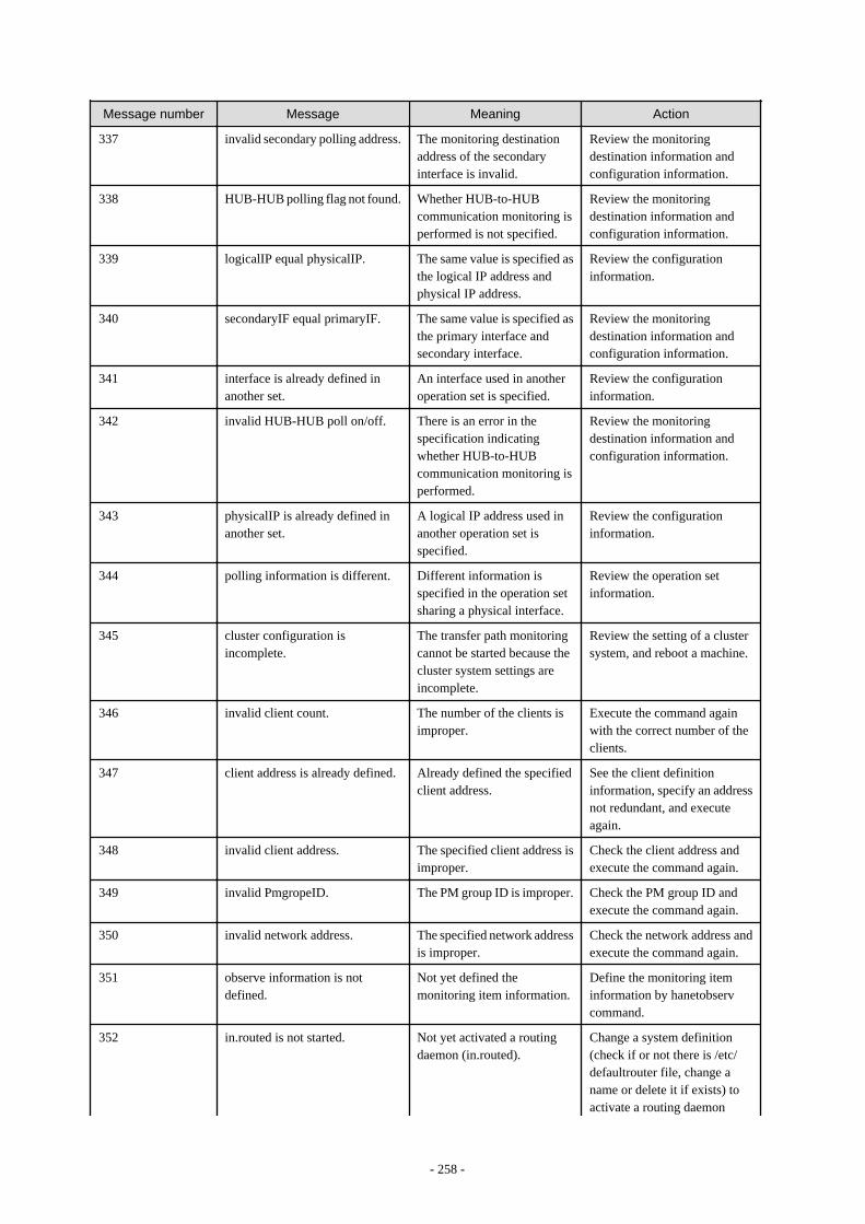
Message number Message Meaning Action
337 invalid secondary polling address. The monitoring destinationaddress of the secondaryinterface is invalid.
Review the monitoringdestination information andconfiguration information.
338 HUB-HUB polling flag not found. Whether HUB-to-HUBcommunication monitoring isperformed is not specified.
Review the monitoringdestination information andconfiguration information.
339 logicalIP equal physicalIP. The same value is specified asthe logical IP address andphysical IP address.
Review the configurationinformation.
340 secondaryIF equal primaryIF. The same value is specified asthe primary interface andsecondary interface.
Review the monitoringdestination information andconfiguration information.
341 interface is already defined inanother set.
An interface used in anotheroperation set is specified.
Review the configurationinformation.
342 invalid HUB-HUB poll on/off. There is an error in thespecification indicatingwhether HUB-to-HUBcommunication monitoring isperformed.
Review the monitoringdestination information andconfiguration information.
343 physicalIP is already defined inanother set.
A logical IP address used inanother operation set isspecified.
Review the configurationinformation.
344 polling information is different. Different information isspecified in the operation setsharing a physical interface.
Review the operation setinformation.
345 cluster configuration isincomplete.
The transfer path monitoringcannot be started because thecluster system settings areincomplete.
Review the setting of a clustersystem, and reboot a machine.
346 invalid client count. The number of the clients isimproper.
Execute the command againwith the correct number of theclients.
347 client address is already defined. Already defined the specifiedclient address.
See the client definitioninformation, specify an addressnot redundant, and executeagain.
348 invalid client address. The specified client address isimproper.
Check the client address andexecute the command again.
349 invalid PmgropeID. The PM group ID is improper. Check the PM group ID andexecute the command again.
350 invalid network address. The specified network addressis improper.
Check the network address andexecute the command again.
351 observe information is notdefined.
Not yet defined themonitoring item information.
Define the monitoring iteminformation by hanetobservcommand.
352 in.routed is not started. Not yet activated a routingdaemon (in.routed).
Change a system definition(check if or not there is /etc/defaultrouter file, change aname or delete it if exists) toactivate a routing daemon
- 258 -
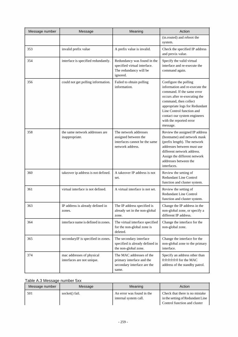
Message number Message Meaning Action
(in.routed) and reboot thesystem.
353 invalid prefix value A prefix value is invalid. Check the specified IP addressand previx value.
354 interface is specified redundantly. Redundancy was found in thespecified virtual interface.The redundancy will beignored.
Specify the valid virtualinterface and re-execute thecommand again.
356 could not get polling information. Failed to obtain pollinginformation.
Configure the pollinginformation and re-execute thecommand. If the same erroroccurs after re-executing thecommand, then collectappropriate logs for RedundantLine Control function andcontact our system engineerswith the reported errormessage.
358 the same network addresses areinappropriate.
The network addressesassigned between theinterfaces cannot be the samenetwork address.
Review the assigned IP address(hostname) and network mask(prefix length). The networkaddresses between must usedifferent network address.Assign the different networkaddresses between theinterfaces.
360 takeover ip address is not defined. A takeover IP address is notset.
Review the setting ofRedundant Line Controlfunction and cluster system.
361 virtual interface is not defined. A virtual interface is not set. Review the setting ofRedundant Line Controlfunction and cluster system.
363 IP address is already defined inzones.
The IP address specified isalready set in the non-globalzone.
Change the IP address in thenon-global zone, or specify adifferent IP address.
364 interface name is defined in zones. The virtual interface specifiedfor the non-global zone isdeleted.
Change the interface for thenon-global zone.
365 secondaryIF is specified in zones. The secondary interfacespecified is already defined inthe non-global zone.
Change the interface for thenon-global zone to the primaryinterface.
374 mac addresses of physicalinterfaces are not unique.
The MAC addresses of theprimary interface and thesecondary interface are thesame.
Specify an address other than0:0:0:0:0:0 for the MACaddress of the standby patrol.
Table A.3 Message number 5xx
Message number Message Meaning Action
501 socket() fail. An error was found in theinternal system call.
Check that there is no mistakein the setting of Redundant LineControl function and cluster
- 259 -

Message number Message Meaning Action
system. After checked there isno mistake, execute a commandagain. If the same phenomenonoccurs, collect materials forexamination of Redundant LineControl function and clustersystem, and contact fieldengineers to report the errormessage. See the manual of acluster system as to thematerials necessary forexamining a cluster system.
502 ioctl(SIOCGIFCONF) fail. An error was found in theinternal system call.
Check that there is no mistakein the setting of Redundant LineControl function and clustersystem. After checked there isno mistake, execute a commandagain. If the same phenomenonoccurs, collect materials forexamination of Redundant LineControl function and clustersystem, and contact fieldengineers to report the errormessage. See the manual of acluster system as to thematerials necessary forexamining a cluster system.
510 could not allocate memory. An error was found in theinternal system call.
Execute a command again. Ifthe same phenomenon occurs,collect materials forexamination of Redundant LineControl function and clustersystem, and then contact fieldengineers to report the errormessage. See the manual of acluster system as to thematerials necessary forexamining a cluster system.
511 could not open file. An error was found in theinternal system call.
Execute a command again. Ifthe same phenomenon occurs,collect materials forexamination of Redundant LineControl function, and thencontact field engineers to reportthe error message.
512 could not read file. An error was found in theinternal system call.
Execute a command again. Ifthe same phenomenon occurs,collect materials forexamination of Redundant LineControl function, and thencontact field engineers to reportthe error message.
513 could not write file. An error was found in theinternal system call.
Execute a command again. Ifthe same phenomenon occurs,
- 260 -
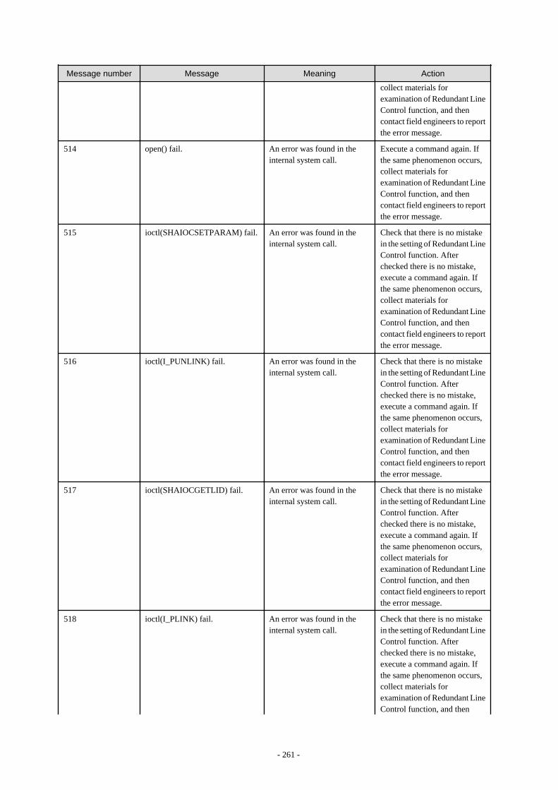
Message number Message Meaning Action
collect materials forexamination of Redundant LineControl function, and thencontact field engineers to reportthe error message.
514 open() fail. An error was found in theinternal system call.
Execute a command again. Ifthe same phenomenon occurs,collect materials forexamination of Redundant LineControl function, and thencontact field engineers to reportthe error message.
515 ioctl(SHAIOCSETPARAM) fail. An error was found in theinternal system call.
Check that there is no mistakein the setting of Redundant LineControl function. Afterchecked there is no mistake,execute a command again. Ifthe same phenomenon occurs,collect materials forexamination of Redundant LineControl function, and thencontact field engineers to reportthe error message.
516 ioctl(I_PUNLINK) fail. An error was found in theinternal system call.
Check that there is no mistakein the setting of Redundant LineControl function. Afterchecked there is no mistake,execute a command again. Ifthe same phenomenon occurs,collect materials forexamination of Redundant LineControl function, and thencontact field engineers to reportthe error message.
517 ioctl(SHAIOCGETLID) fail. An error was found in theinternal system call.
Check that there is no mistakein the setting of Redundant LineControl function. Afterchecked there is no mistake,execute a command again. Ifthe same phenomenon occurs,collect materials forexamination of Redundant LineControl function, and thencontact field engineers to reportthe error message.
518 ioctl(I_PLINK) fail. An error was found in theinternal system call.
Check that there is no mistakein the setting of Redundant LineControl function. Afterchecked there is no mistake,execute a command again. Ifthe same phenomenon occurs,collect materials forexamination of Redundant LineControl function, and then
- 261 -
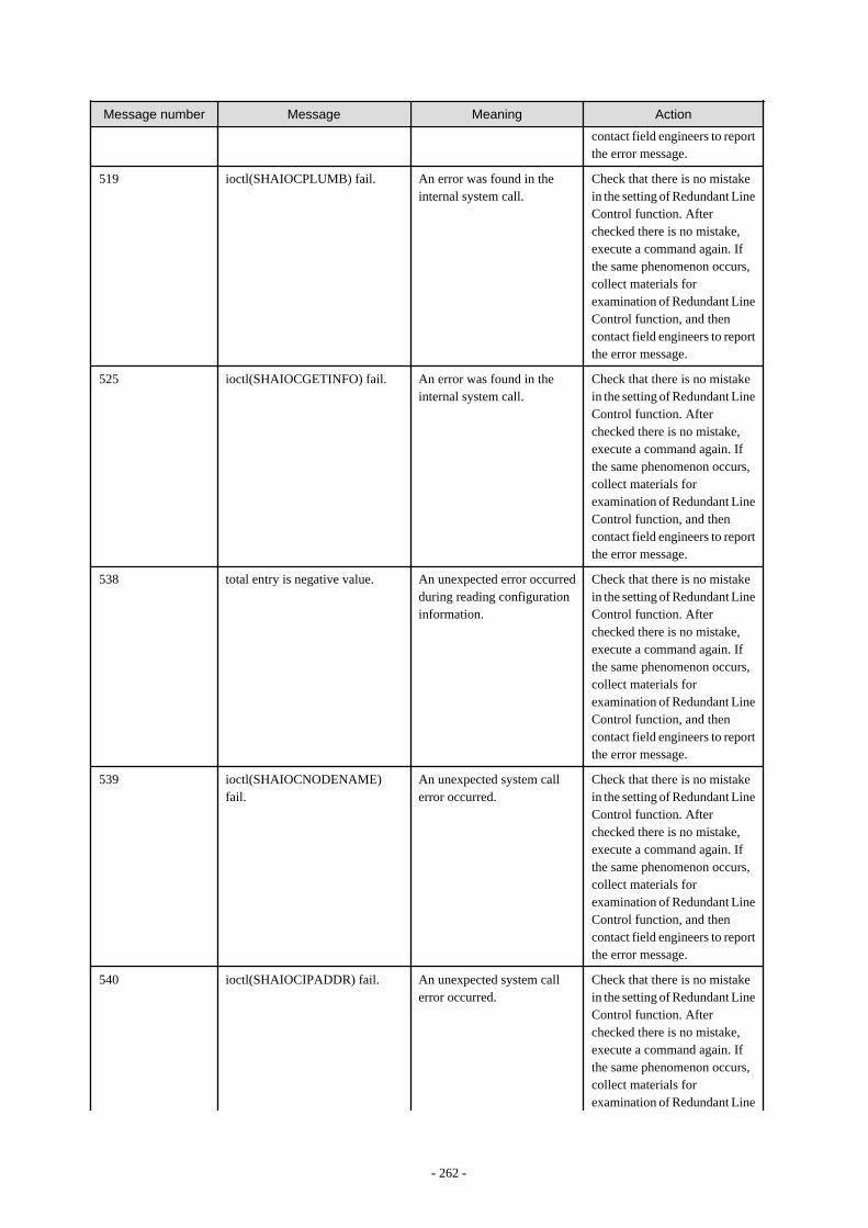
Message number Message Meaning Action
contact field engineers to reportthe error message.
519 ioctl(SHAIOCPLUMB) fail. An error was found in theinternal system call.
Check that there is no mistakein the setting of Redundant LineControl function. Afterchecked there is no mistake,execute a command again. Ifthe same phenomenon occurs,collect materials forexamination of Redundant LineControl function, and thencontact field engineers to reportthe error message.
525 ioctl(SHAIOCGETINFO) fail. An error was found in theinternal system call.
Check that there is no mistakein the setting of Redundant LineControl function. Afterchecked there is no mistake,execute a command again. Ifthe same phenomenon occurs,collect materials forexamination of Redundant LineControl function, and thencontact field engineers to reportthe error message.
538 total entry is negative value. An unexpected error occurredduring reading configurationinformation.
Check that there is no mistakein the setting of Redundant LineControl function. Afterchecked there is no mistake,execute a command again. Ifthe same phenomenon occurs,collect materials forexamination of Redundant LineControl function, and thencontact field engineers to reportthe error message.
539 ioctl(SHAIOCNODENAME)fail.
An unexpected system callerror occurred.
Check that there is no mistakein the setting of Redundant LineControl function. Afterchecked there is no mistake,execute a command again. Ifthe same phenomenon occurs,collect materials forexamination of Redundant LineControl function, and thencontact field engineers to reportthe error message.
540 ioctl(SHAIOCIPADDR) fail. An unexpected system callerror occurred.
Check that there is no mistakein the setting of Redundant LineControl function. Afterchecked there is no mistake,execute a command again. Ifthe same phenomenon occurs,collect materials forexamination of Redundant Line
- 262 -
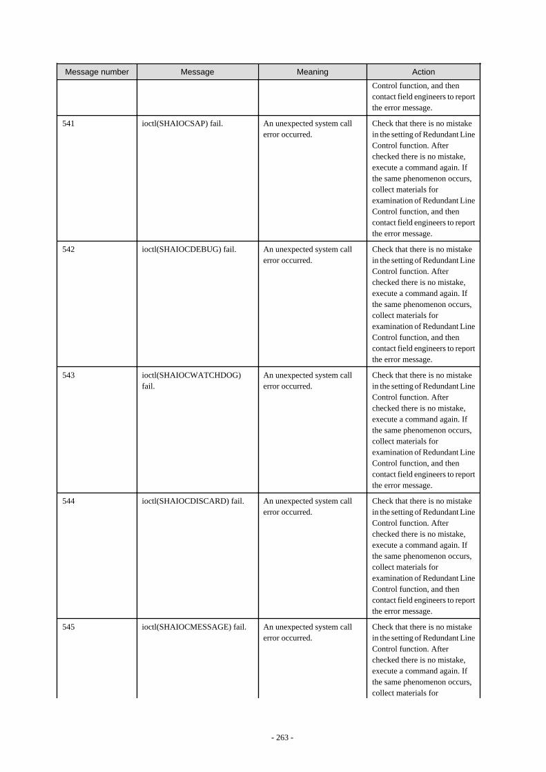
Message number Message Meaning Action
Control function, and thencontact field engineers to reportthe error message.
541 ioctl(SHAIOCSAP) fail. An unexpected system callerror occurred.
Check that there is no mistakein the setting of Redundant LineControl function. Afterchecked there is no mistake,execute a command again. Ifthe same phenomenon occurs,collect materials forexamination of Redundant LineControl function, and thencontact field engineers to reportthe error message.
542 ioctl(SHAIOCDEBUG) fail. An unexpected system callerror occurred.
Check that there is no mistakein the setting of Redundant LineControl function. Afterchecked there is no mistake,execute a command again. Ifthe same phenomenon occurs,collect materials forexamination of Redundant LineControl function, and thencontact field engineers to reportthe error message.
543 ioctl(SHAIOCWATCHDOG)fail.
An unexpected system callerror occurred.
Check that there is no mistakein the setting of Redundant LineControl function. Afterchecked there is no mistake,execute a command again. Ifthe same phenomenon occurs,collect materials forexamination of Redundant LineControl function, and thencontact field engineers to reportthe error message.
544 ioctl(SHAIOCDISCARD) fail. An unexpected system callerror occurred.
Check that there is no mistakein the setting of Redundant LineControl function. Afterchecked there is no mistake,execute a command again. Ifthe same phenomenon occurs,collect materials forexamination of Redundant LineControl function, and thencontact field engineers to reportthe error message.
545 ioctl(SHAIOCMESSAGE) fail. An unexpected system callerror occurred.
Check that there is no mistakein the setting of Redundant LineControl function. Afterchecked there is no mistake,execute a command again. Ifthe same phenomenon occurs,collect materials for
- 263 -

Message number Message Meaning Action
examination of Redundant LineControl function, and thencontact field engineers to reportthe error message.
546 unexpected error. An unexpected system callerror occurred.
Execute a command again. Ifthe same phenomenon occurs,collect materials forexamination of Redundant LineControl function, and thencontact field engineers to reportthe error message.
547 ioctl(SIOCGIFFLAGS) fail. An unexpected system callerror occurred.
Check that there is no mistakein the setting of Redundant LineControl function. Afterchecked there is no mistake,execute a command again. Ifthe same phenomenon occurs,collect materials forexamination of Redundant LineControl function, and thencontact field engineers to reportthe error message.
548 ioctl(SIOCGIFNUM) fail. An unexpected system callerror occurred.
Check that there is no mistakein the setting of Redundant LineControl function. Afterchecked there is no mistake,execute a command again. Ifthe same phenomenon occurs,collect materials forexamination of Redundant LineControl function, and thencontact field engineers to reportthe error message.
549 polling process is inactive. An internal process was notexecuted.
Collect materials forexamination of Redundant LineControl function, and thencontact field engineers to reportthe error message.
550 opendir failed. An unexpected system callerror occurred.
Check that there is no mistakein the setting of Redundant LineControl function. Afterchecked there is no mistake,execute a command again. Ifthe same phenomenon occurs,collect materials forexamination of Redundant LineControl function, and thencontact field engineers to reportthe error message.
551 semaphore lock failed. An error was found in theinternal system call.
Collect materials forexamination of Redundant LineControl function, and thencontact field engineers to reportthe error message.
- 264 -
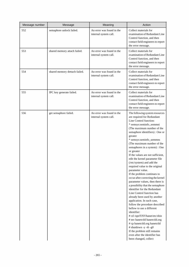
Message number Message Meaning Action
552 semaphore unlock failed. An error was found in theinternal system call.
Collect materials forexamination of Redundant LineControl function, and thencontact field engineers to reportthe error message.
553 shared memory attach failed. An error was found in theinternal system call.
Collect materials forexamination of Redundant LineControl function, and thencontact field engineers to reportthe error message.
554 shared memory dettach failed. An error was found in theinternal system call.
Collect materials forexamination of Redundant LineControl function, and thencontact field engineers to reportthe error message.
555 IPC key generate failed. An error was found in theinternal system call.
Collect materials forexamination of Redundant LineControl function, and thencontact field engineers to reportthe error message.
556 get semaphore failed. An error was found in theinternal system call.
The following system resourcesare required for RedundantLine Control function:* semsys:seminfo_semmni(The maximum number of thesemaphore identifiers) : One orgreater* semsys:seminfo_semmns(The maximum number of thesemaphores in a system) : Oneor greaterIf the values are not sufficient,edit the kernel parameter file(/etc/system) and add therequired value to the originalparameter value.If the problem continues tooccur after correcting the kernelparameter values, then there isa possibility that the semaphoreidentifier for the RedundantLine Control function hasalready been used by anotherapplication. In such case,follow the procedure describedbellow to use a differentidentifier:# cd /opt/FJSVhanet/etc/sbin# mv hanetctld hanetctld.org# cp hanetctld.org hanetctld# shutdown -y -i6 -g0If the problem still remainseven after the identifier hasbeen changed, collect
- 265 -

Message number Message Meaning Action
examination materials ofRedundant Line Controlfunction and contact fieldengineers.
557 get shared memory segmentidentifier failed.
An error was found in theinternal system call.
The following system resourcesare required for RedundantLine Control function:* shmsys:shminfo_shmmax(The maximum size of theshared memory segment) :5120 or greater* shmsys:shminfo_shmmni(The maximum number of theshared memory segments) : twoor greaterIf the values are not sufficient,edit the kernel parameter file(/etc/system) and add therequired value to the originalparameter value.Additionally, do not specifyshmsys:shminfo_shmmin(minimum size of the shared memorysegment).If the problem continues tooccur after correcting the kernelparameter values, then there isa possibility that the sharedmemory identifier for theRedundant Line Controlfunction has already been usedby another application. In suchcase, follow the proceduredescribed bellow to use adifferent identifier:# cd /opt/FJSVhanet/etc/sbin# mv hanetselecthanetselect.org# cp hanetselect.org hanetselectIf the problem still remainseven after the identifier hasbeen changed, collectexamination materials ofRedundant Line Controlfunction, and contact fieldengineers.
558 control semaphore failed. An error was found in theinternal system call.
Collect materials forexamination of Redundant LineControl function, and thencontact field engineers to reportthe error message.
559 internal error. An internal error occurred. Collect materials forexamination of Redundant LineControl function, and then
- 266 -
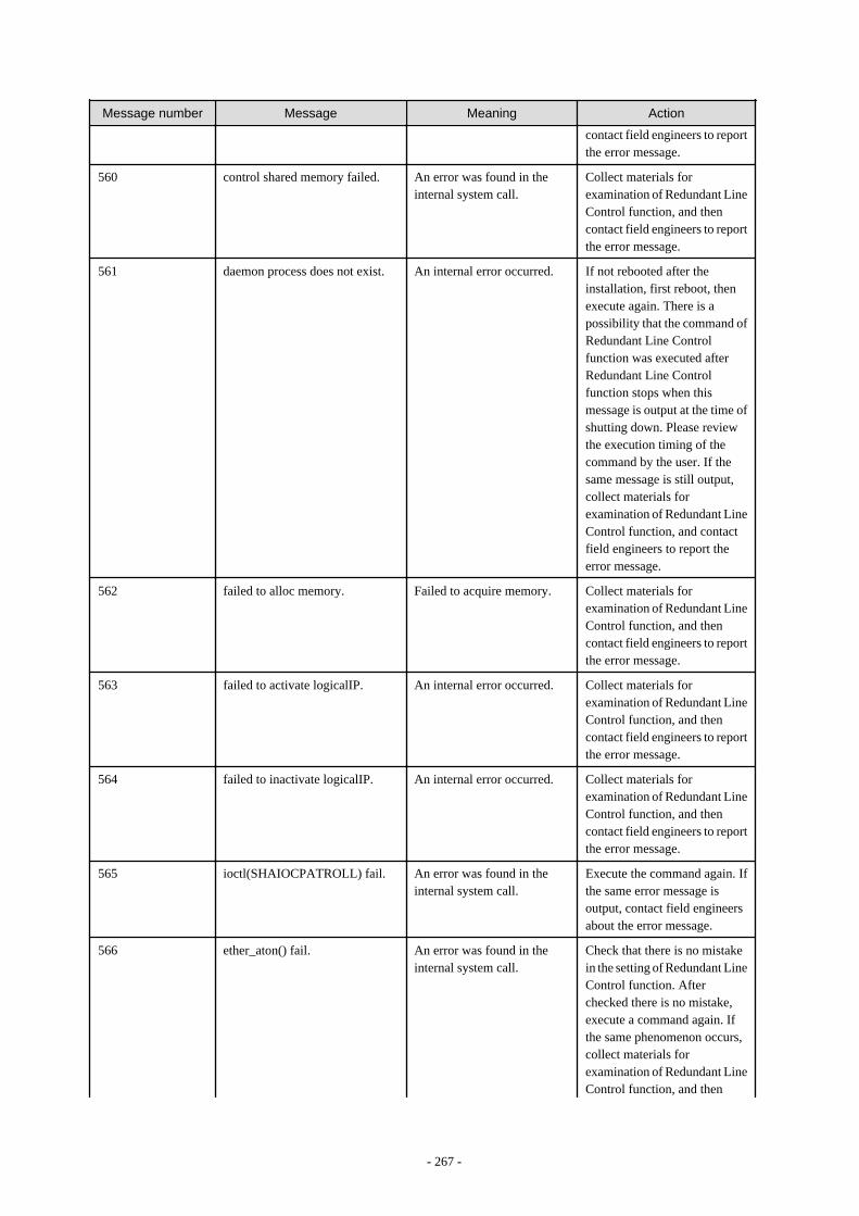
Message number Message Meaning Action
contact field engineers to reportthe error message.
560 control shared memory failed. An error was found in theinternal system call.
Collect materials forexamination of Redundant LineControl function, and thencontact field engineers to reportthe error message.
561 daemon process does not exist. An internal error occurred. If not rebooted after theinstallation, first reboot, thenexecute again. There is apossibility that the command ofRedundant Line Controlfunction was executed afterRedundant Line Controlfunction stops when thismessage is output at the time ofshutting down. Please reviewthe execution timing of thecommand by the user. If thesame message is still output,collect materials forexamination of Redundant LineControl function, and contactfield engineers to report theerror message.
562 failed to alloc memory. Failed to acquire memory. Collect materials forexamination of Redundant LineControl function, and thencontact field engineers to reportthe error message.
563 failed to activate logicalIP. An internal error occurred. Collect materials forexamination of Redundant LineControl function, and thencontact field engineers to reportthe error message.
564 failed to inactivate logicalIP. An internal error occurred. Collect materials forexamination of Redundant LineControl function, and thencontact field engineers to reportthe error message.
565 ioctl(SHAIOCPATROLL) fail. An error was found in theinternal system call.
Execute the command again. Ifthe same error message isoutput, contact field engineersabout the error message.
566 ether_aton() fail. An error was found in theinternal system call.
Check that there is no mistakein the setting of Redundant LineControl function. Afterchecked there is no mistake,execute a command again. Ifthe same phenomenon occurs,collect materials forexamination of Redundant LineControl function, and then
- 267 -
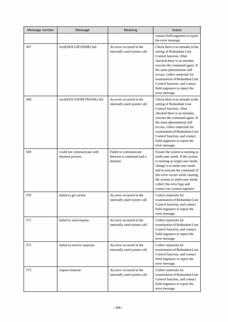
Message number Message Meaning Action
contact field engineers to reportthe error message.
567 ioctl(SIOCGIFADDR) fail. An error occurred in theinternally used system call.
Check there is no mistake in thesetting of Redundant LineControl function. Afterchecked there is no mistake,execute the command again. Ifthe same phenomenon stilloccurs, collect materials forexamination of Redundant LineControl function, and contactfield engineers to report theerror message.
568 ioctl(SIOCGIFNETMASK) fail. An error occurred in theinternally used system call.
Check there is no mistake in thesetting of Redundant LineControl function. Afterchecked there is no mistake,execute the command again. Ifthe same phenomenon stilloccurs, collect materials forexamination of Redundant LineControl function, and contactfield engineers to report theerror message.
569 could not communicate withdaemon process.
Failed to communicatebetween a command and adaemon.
Ensure the system is running asmulti-user mode. If the systemis running as single user mode,change it to multi-user modeand re-execute the command. Ifthis error occurs while runningthe system as multi-user mode,collect the error logs andcontact our system engineer.
570 failed to get socket. An error occurred in theinternally used system call.
Collect materials forexamination of Redundant LineControl function, and contactfield engineers to report theerror message.
571 failed to send request. An error occurred in theinternally used system call.
Collect materials forexamination of Redundant LineControl function, and contactfield engineers to report theerror message.
572 failed to receive response. An error occurred in theinternally used system call.
Collect materials forexamination of Redundant LineControl function, and contactfield engineers to report theerror message.
573 request timeout. An error occurred in theinternally used system call.
Collect materials forexamination of Redundant LineControl function, and contactfield engineers to report theerror message.
- 268 -
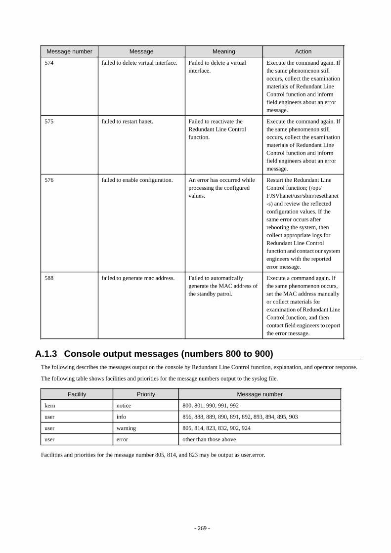
Message number Message Meaning Action
574 failed to delete virtual interface. Failed to delete a virtualinterface.
Execute the command again. Ifthe same phenomenon stilloccurs, collect the examinationmaterials of Redundant LineControl function and informfield engineers about an errormessage.
575 failed to restart hanet. Failed to reactivate theRedundant Line Controlfunction.
Execute the command again. Ifthe same phenomenon stilloccurs, collect the examinationmaterials of Redundant LineControl function and informfield engineers about an errormessage.
576 failed to enable configuration. An error has occurred whileprocessing the configuredvalues.
Restart the Redundant LineControl function; (/opt/FJSVhanet/usr/sbin/resethanet-s) and review the reflectedconfiguration values. If thesame error occurs afterrebooting the system, thencollect appropriate logs forRedundant Line Controlfunction and contact our systemengineers with the reportederror message.
588 failed to generate mac address. Failed to automaticallygenerate the MAC address ofthe standby patrol.
Execute a command again. Ifthe same phenomenon occurs,set the MAC address manuallyor collect materials forexamination of Redundant LineControl function, and thencontact field engineers to reportthe error message.
A.1.3 Console output messages (numbers 800 to 900)The following describes the messages output on the console by Redundant Line Control function, explanation, and operator response.
The following table shows facilities and priorities for the message numbers output to the syslog file.
Facility Priority Message number
kern notice 800, 801, 990, 991, 992
user info 856, 888, 889, 890, 891, 892, 893, 894, 895, 903
user warning 805, 814, 823, 832, 902, 924
user error other than those above
Facilities and priorities for the message number 805, 814, and 823 may be output as user.error.
- 269 -
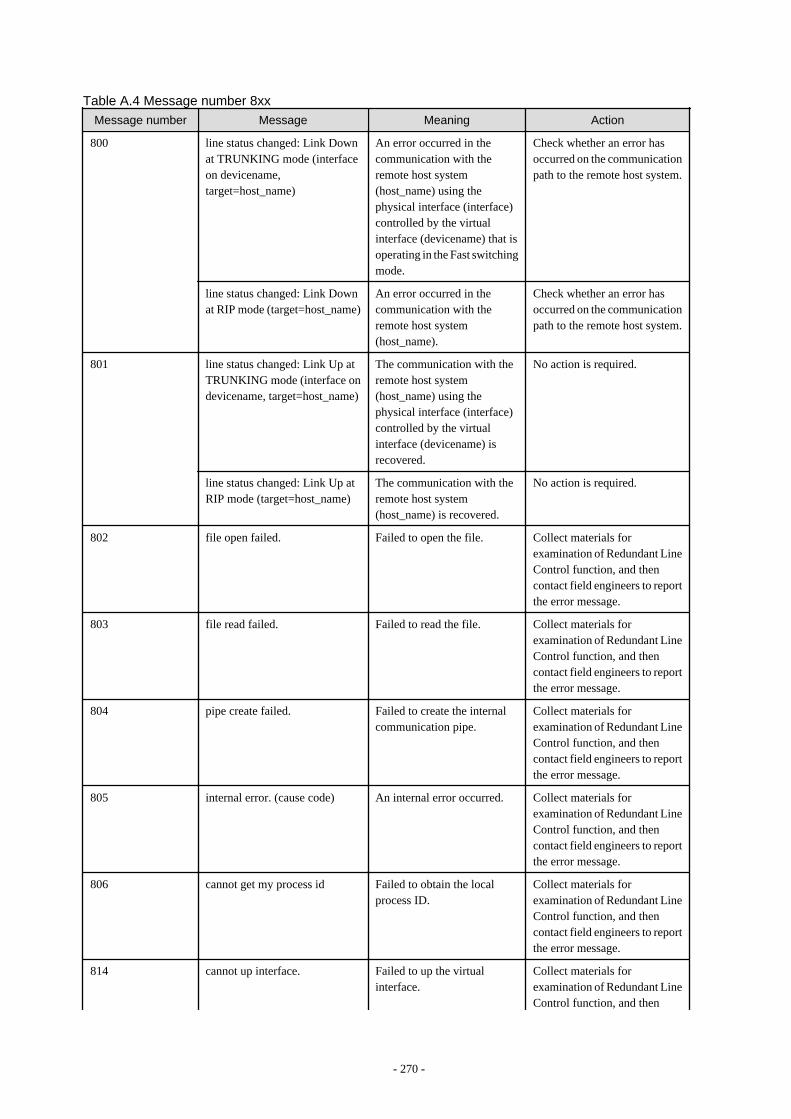
Table A.4 Message number 8xxMessage number Message Meaning Action
800 line status changed: Link Downat TRUNKING mode (interfaceon devicename,target=host_name)
An error occurred in thecommunication with theremote host system(host_name) using thephysical interface (interface)controlled by the virtualinterface (devicename) that isoperating in the Fast switchingmode.
Check whether an error hasoccurred on the communicationpath to the remote host system.
line status changed: Link Downat RIP mode (target=host_name)
An error occurred in thecommunication with theremote host system(host_name).
Check whether an error hasoccurred on the communicationpath to the remote host system.
801 line status changed: Link Up atTRUNKING mode (interface ondevicename, target=host_name)
The communication with theremote host system(host_name) using thephysical interface (interface)controlled by the virtualinterface (devicename) isrecovered.
No action is required.
line status changed: Link Up atRIP mode (target=host_name)
The communication with theremote host system(host_name) is recovered.
No action is required.
802 file open failed. Failed to open the file. Collect materials forexamination of Redundant LineControl function, and thencontact field engineers to reportthe error message.
803 file read failed. Failed to read the file. Collect materials forexamination of Redundant LineControl function, and thencontact field engineers to reportthe error message.
804 pipe create failed. Failed to create the internalcommunication pipe.
Collect materials forexamination of Redundant LineControl function, and thencontact field engineers to reportthe error message.
805 internal error. (cause code) An internal error occurred. Collect materials forexamination of Redundant LineControl function, and thencontact field engineers to reportthe error message.
806 cannot get my process id Failed to obtain the localprocess ID.
Collect materials forexamination of Redundant LineControl function, and thencontact field engineers to reportthe error message.
814 cannot up interface. Failed to up the virtualinterface.
Collect materials forexamination of Redundant LineControl function, and then
- 270 -
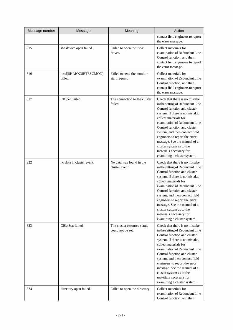
Message number Message Meaning Action
contact field engineers to reportthe error message.
815 sha device open failed. Failed to open the "sha"driver.
Collect materials forexamination of Redundant LineControl function, and thencontact field engineers to reportthe error message.
816 ioctl(SHAIOCSETRSCMON)failed.
Failed to send the monitorstart request.
Collect materials forexamination of Redundant LineControl function, and thencontact field engineers to reportthe error message.
817 ClOpen failed. The connection to the clusterfailed.
Check that there is no mistakein the setting of Redundant LineControl function and clustersystem. If there is no mistake,collect materials forexamination of Redundant LineControl function and clustersystem, and then contact fieldengineers to report the errormessage. See the manual of acluster system as to thematerials necessary forexamining a cluster system.
822 no data in cluster event. No data was found in thecluster event.
Check that there is no mistakein the setting of Redundant LineControl function and clustersystem. If there is no mistake,collect materials forexamination of Redundant LineControl function and clustersystem, and then contact fieldengineers to report the errormessage. See the manual of acluster system as to thematerials necessary forexamining a cluster system.
823 ClSetStat failed. The cluster resource statuscould not be set.
Check that there is no mistakein the setting of Redundant LineControl function and clustersystem. If there is no mistake,collect materials forexamination of Redundant LineControl function and clustersystem, and then contact fieldengineers to report the errormessage. See the manual of acluster system as to thematerials necessary forexamining a cluster system.
824 directory open failed. Failed to open the directory. Collect materials forexamination of Redundant LineControl function, and then
- 271 -

Message number Message Meaning Action
contact field engineers to reportthe error message.
825 signal send failed. Failed to send the signal. Collect materials forexamination of Redundant LineControl function, and thencontact field engineers to reportthe error message.
826 command can be executed onlywith super-user.
The execution-time authorityis invalid.
Collect materials forexamination of Redundant LineControl function, and thencontact field engineers to reportthe error message.
827 could not allocate memory. Failed to obtain the memory. Collect materials forexamination of Redundant LineControl function, and thencontact field engineers to reportthe error message.
828 fork failed. The fork () failed. Collect materials forexamination of Redundant LineControl function, and thencontact field engineers to reportthe error message.
829 child process execute failed. Failed to generate the childprocess.
Collect materials forexamination of Redundant LineControl function, and thencontact field engineers to reportthe error message.
830 getmsg failed. Failed to receive the data fromthe "sha" driver.
Collect materials forexamination of Redundant LineControl function, and thencontact field engineers to reportthe error message.
831 shared library address get failed. Failed to obtain the sharedlibrary address.
Collect materials forexamination of Redundant LineControl function, and thencontact field engineers to reportthe error message.
832 poll failed. The poll () failed. Collect materials forexamination of Redundant LineControl function, and thencontact field engineers to reportthe error message.
833 ioctl(SHAIOCSETIPADDR)failed.
Failed to notify the IP address. Collect materials forexamination of Redundant LineControl function, and thencontact field engineers to reportthe error message.
840 polling device name is notdefined in configurationinformation. polling is notstarted.ifname=interface(details)
The transmission linemonitoring cannot be startedbecause the definitioninformation of the virtualinterface is disabled.
The host name that is defined asthe IP address of the virtualinterface may be deleted from /etc/inet/hosts file. Check the
- 272 -
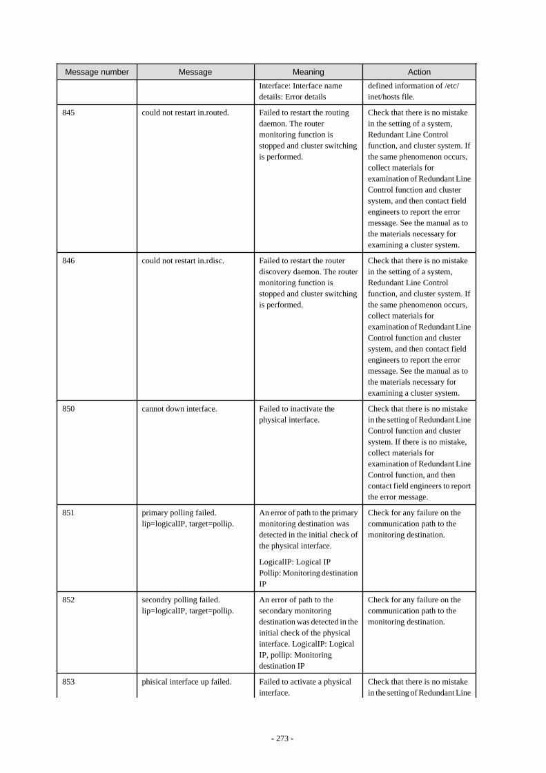
Message number Message Meaning Action
Interface: Interface namedetails: Error details
defined information of /etc/inet/hosts file.
845 could not restart in.routed. Failed to restart the routingdaemon. The routermonitoring function isstopped and cluster switchingis performed.
Check that there is no mistakein the setting of a system,Redundant Line Controlfunction, and cluster system. Ifthe same phenomenon occurs,collect materials forexamination of Redundant LineControl function and clustersystem, and then contact fieldengineers to report the errormessage. See the manual as tothe materials necessary forexamining a cluster system.
846 could not restart in.rdisc. Failed to restart the routerdiscovery daemon. The routermonitoring function isstopped and cluster switchingis performed.
Check that there is no mistakein the setting of a system,Redundant Line Controlfunction, and cluster system. Ifthe same phenomenon occurs,collect materials forexamination of Redundant LineControl function and clustersystem, and then contact fieldengineers to report the errormessage. See the manual as tothe materials necessary forexamining a cluster system.
850 cannot down interface. Failed to inactivate thephysical interface.
Check that there is no mistakein the setting of Redundant LineControl function and clustersystem. If there is no mistake,collect materials forexamination of Redundant LineControl function, and thencontact field engineers to reportthe error message.
851 primary polling failed.lip=logicalIP, target=pollip.
An error of path to the primarymonitoring destination wasdetected in the initial check ofthe physical interface.
LogicalIP: Logical IPPollip: Monitoring destinationIP
Check for any failure on thecommunication path to themonitoring destination.
852 secondry polling failed.lip=logicalIP, target=pollip.
An error of path to thesecondary monitoringdestination was detected in theinitial check of the physicalinterface. LogicalIP: LogicalIP, pollip: Monitoringdestination IP
Check for any failure on thecommunication path to themonitoring destination.
853 phisical interface up failed. Failed to activate a physicalinterface.
Check that there is no mistakein the setting of Redundant Line
- 273 -
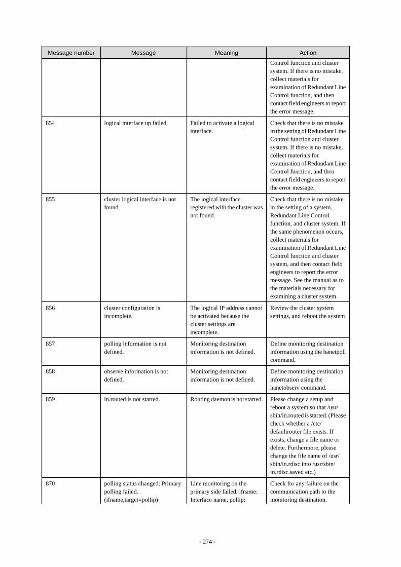
Message number Message Meaning Action
Control function and clustersystem. If there is no mistake,collect materials forexamination of Redundant LineControl function, and thencontact field engineers to reportthe error message.
854 logical interface up failed. Failed to activate a logicalinterface.
Check that there is no mistakein the setting of Redundant LineControl function and clustersystem. If there is no mistake,collect materials forexamination of Redundant LineControl function, and thencontact field engineers to reportthe error message.
855 cluster logical interface is notfound.
The logical interfaceregistered with the cluster wasnot found.
Check that there is no mistakein the setting of a system,Redundant Line Controlfunction, and cluster system. Ifthe same phenomenon occurs,collect materials forexamination of Redundant LineControl function and clustersystem, and then contact fieldengineers to report the errormessage. See the manual as tothe materials necessary forexamining a cluster system.
856 cluster configuration isincomplete.
The logical IP address cannotbe activated because thecluster settings areincomplete.
Review the cluster systemsettings, and reboot the system
857 polling information is notdefined.
Monitoring destinationinformation is not defined.
Define monitoring destinationinformation using the hanetpollcommand.
858 observe information is notdefined.
Monitoring destinationinformation is not defined.
Define monitoring destinationinformation using thehanetobserv command.
859 in.routed is not started. Routing daemon is not started. Please change a setup andreboot a system so that /usr/sbin/in.routed is started. (Pleasecheck whether a /etc/defaultrouter file exists. Ifexists, change a file name ordelete. Furthermore, pleasechange the file name of /usr/sbin/in.rdisc into /usr/sbin/in.rdisc.saved etc.)
870 polling status changed: Primarypolling failed.(ifname,target=pollip)
Line monitoring on theprimary side failed. ifname:Interface name, pollip:
Check for any failure on thecommunication path to themonitoring destination.
- 274 -
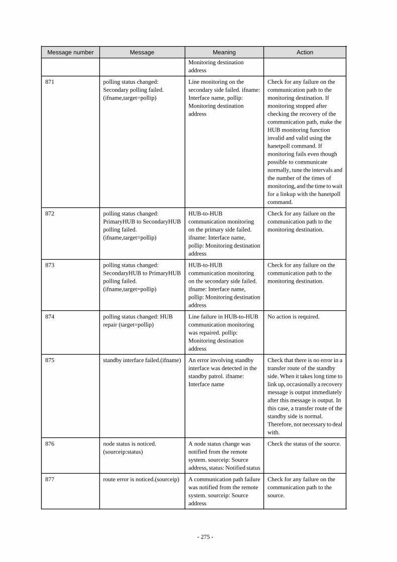
Message number Message Meaning Action
Monitoring destinationaddress
871 polling status changed:Secondary polling failed.(ifname,target=pollip)
Line monitoring on thesecondary side failed. ifname:Interface name, pollip:Monitoring destinationaddress
Check for any failure on thecommunication path to themonitoring destination. Ifmonitoring stopped afterchecking the recovery of thecommunication path, make theHUB monitoring functioninvalid and valid using thehanetpoll command. Ifmonitoring fails even thoughpossible to communicatenormally, tune the intervals andthe number of the times ofmonitoring, and the time to waitfor a linkup with the hanetpollcommand.
872 polling status changed:PrimaryHUB to SecondaryHUBpolling failed.(ifname,target=pollip)
HUB-to-HUBcommunication monitoringon the primary side failed.ifname: Interface name,pollip: Monitoring destinationaddress
Check for any failure on thecommunication path to themonitoring destination.
873 polling status changed:SecondaryHUB to PrimaryHUBpolling failed.(ifname,target=pollip)
HUB-to-HUBcommunication monitoringon the secondary side failed.ifname: Interface name,pollip: Monitoring destinationaddress
Check for any failure on thecommunication path to themonitoring destination.
874 polling status changed: HUBrepair (target=pollip)
Line failure in HUB-to-HUBcommunication monitoringwas repaired. pollip:Monitoring destinationaddress
No action is required.
875 standby interface failed.(ifname) An error involving standbyinterface was detected in thestandby patrol. ifname:Interface name
Check that there is no error in atransfer route of the standbyside. When it takes long time tolink up, occasionally a recoverymessage is output immediatelyafter this message is output. Inthis case, a transfer route of thestandby side is normal.Therefore, not necessary to dealwith.
876 node status is noticed.(sourceip:status)
A node status change wasnotified from the remotesystem. sourceip: Sourceaddress, status: Notified status
Check the status of the source.
877 route error is noticed.(sourceip) A communication path failurewas notified from the remotesystem. sourceip: Sourceaddress
Check for any failure on thecommunication path to thesource.
- 275 -
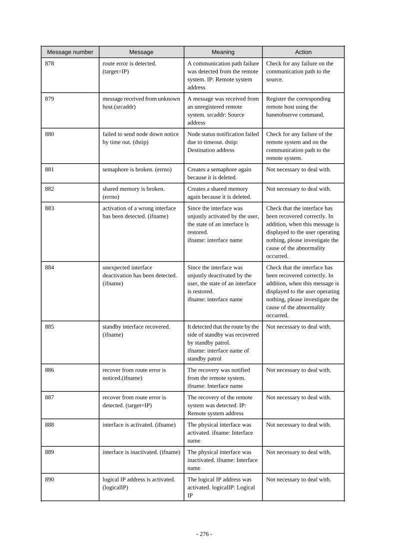
Message number Message Meaning Action
878 route error is detected.(target=IP)
A communication path failurewas detected from the remotesystem. IP: Remote systemaddress
Check for any failure on thecommunication path to thesource.
879 message received from unknownhost.(srcaddr)
A message was received froman unregistered remotesystem. srcaddr: Sourceaddress
Register the correspondingremote host using thehanetobserve command.
880 failed to send node down noticeby time out. (dstip)
Node status notification faileddue to timeout. dstip:Destination address
Check for any failure of theremote system and on thecommunication path to theremote system.
881 semaphore is broken. (errno) Creates a semaphore againbecause it is deleted.
Not necessary to deal with.
882 shared memory is broken.(errno)
Creates a shared memoryagain because it is deleted.
Not necessary to deal with.
883 activation of a wrong interfacehas been detected. (ifname)
Since the interface wasunjustly activated by the user,the state of an interface isrestored.ifname: interface name
Check that the interface hasbeen recovered correctly. Inaddition, when this message isdisplayed to the user operatingnothing, please investigate thecause of the abnormalityoccurred.
884 unexpected interfacedeactivation has been detected.(ifname)
Since the interface wasunjustly deactivated by theuser, the state of an interfaceis restored.ifname: interface name
Check that the interface hasbeen recovered correctly. Inaddition, when this message isdisplayed to the user operatingnothing, please investigate thecause of the abnormalityoccurred.
885 standby interface recovered.(ifname)
It detected that the route by theside of standby was recoveredby standby patrol.ifname: interface name ofstandby patrol
Not necessary to deal with.
886 recover from route error isnoticed.(ifname)
The recovery was notifiedfrom the remote system.ifname: Interface name
Not necessary to deal with.
887 recover from route error isdetected. (target=IP)
The recovery of the remotesystem was detected. IP:Remote system address
Not necessary to deal with.
888 interface is activated. (ifname) The physical interface wasactivated. ifname: Interfacename
Not necessary to deal with.
889 interface is inactivated. (ifname) The physical interface wasinactivated. ifname: Interfacename
Not necessary to deal with.
890 logical IP address is activated.(logicalIP)
The logical IP address wasactivated. logicalIP: LogicalIP
Not necessary to deal with.
- 276 -
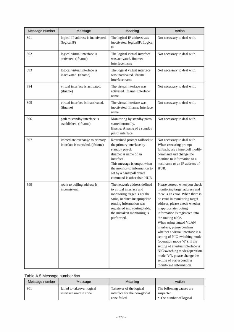
Message number Message Meaning Action
891 logical IP address is inactivated.(logicalIP)
The logical IP address wasinactivated. logicalIP: LogicalIP
Not necessary to deal with.
892 logical virtual interface isactivated. (ifname)
The logical virtual interfacewas activated. ifname:Interface name
Not necessary to deal with.
893 logical virtual interface isinactivated. (ifname)
The logical virtual interfacewas inactivated. ifname:Interface name
Not necessary to deal with.
894 virtual interface is activated.(ifname)
The virtual interface wasactivated. ifname: Interfacename
Not necessary to deal with.
895 virtual interface is inactivated.(ifname)
The virtual interface wasinactivated. ifname: Interfacename
Not necessary to deal with.
896 path to standby interface isestablished. (ifname)
Monitoring by standby patrolstarted normally.Ifname: A name of a standbypatrol interface.
Not necessary to deal with.
897 immediate exchange to primaryinterface is canceled. (ifname)
Restrained prompt failback tothe primary interface bystandby patrol.ifname: A name of aninterface.This message is output whenthe monitor-to information toset by a hanetpoll createcommand is other than HUB.
Not necessary to deal with.When executing promptfailback, use a hanetpoll modifycommand and change themonitor-to information to ahost name or an IP address ofHUB.
899 route to polling address isinconsistent.
The network address definedto virtual interface andmonitoring target is not thesame, or since inappropriaterouting information wasregistered into routing table,the mistaken monitoring isperformed.
Please correct, when you checkmonitoring target address andthere is an error. When there isno error in monitoring targetaddress, please check whetherinappropriate routinginformation is registered intothe routing table.When using tagged VLANinterface, please confirmwhether a virtual interface is asetting of NIC switching mode(operation mode "d"). If thesetting of a virtual interface isNIC switching mode (operationmode "e"), please change thesetting of correspondingmonitoring information.
Table A.5 Message number 9xx
Message number Message Meaning Action
901 failed to takeover logicalinterface used in zone.
Takeover of the logicalinterface for the non-globalzone failed.
The following causes aresuspected:* The number of logical
- 277 -

Message number Message Meaning Action
interfaces reaches themaximum.* The same IP address is usedfor two or more interfaces in thesystem.* The same IP address is usedfor the other node andIPv6.Check the networkinterface and networkenvironment in the system.
902 logical interface of zone wasadded to a secondaryIF.
The logical interface for thenon-global zone was added tothe secondary interface.
The secondary interface is set tothe network interface of thenon-global zone. Changing theinterface to the primaryinterface is highlyrecommended. However, thiswill not affect ongoingoperations because the logicalinterface for the non-globalzone will automatically betaken over to the primaryinterface.
903 succeeded in takeover logicalinterface used in zone.
The logical interface for thenon-global zone wassucceeded.
Not necessary to deal with.
908 hanetctld restarted. GLS control daemon has beenrestarted.
No action is required.
909 failed to restart daemon. Stop of the daemon wasdetected and restart was tried,but failed.
Collect materials forexamination of Redundant LineControl function, and thencontact field engineers to reportthe error message.
924 physical interface is not running.(ifname)
An interface is not linked up.ifname: Interface name
Check whether NIC or HUBfailures occur.
925 exchange interface is canceled.(ifname)
Stops switching NICs becausethe interface of the switchingtarget is not linked up.ifname: Interface name
Check whether NIC or HUBfailures occur.
973 failed to startup self-checking. The self-checking functionfailed to start.
Follow the instructions of thepreviously displayed message.
974 sha driver error has beendetected.
GLS driver error has beendetected.
Follow "2.3.6 Self-checkingfunction" to take theappropriate action.
976 hanetctld error has beendetected.
GLS daemon error has beendetected.
If a recovery message of 977isdisplayed, no action is required.If not displayed, follow "2.3.6Self-checking function" to takethe appropriate action.
977 hanetctld recovery has beendetected.
GLS daemon recovery hasbeen detected.
No action is required.
- 278 -
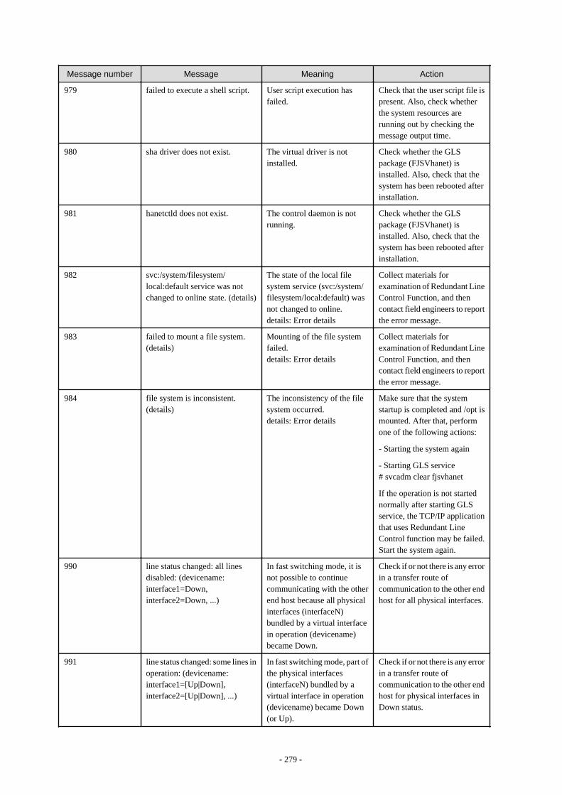
Message number Message Meaning Action
979 failed to execute a shell script. User script execution hasfailed.
Check that the user script file ispresent. Also, check whetherthe system resources arerunning out by checking themessage output time.
980 sha driver does not exist. The virtual driver is notinstalled.
Check whether the GLSpackage (FJSVhanet) isinstalled. Also, check that thesystem has been rebooted afterinstallation.
981 hanetctld does not exist. The control daemon is notrunning.
Check whether the GLSpackage (FJSVhanet) isinstalled. Also, check that thesystem has been rebooted afterinstallation.
982 svc:/system/filesystem/local:default service was notchanged to online state. (details)
The state of the local filesystem service (svc:/system/filesystem/local:default) wasnot changed to online.details: Error details
Collect materials forexamination of Redundant LineControl Function, and thencontact field engineers to reportthe error message.
983 failed to mount a file system.(details)
Mounting of the file systemfailed.details: Error details
Collect materials forexamination of Redundant LineControl Function, and thencontact field engineers to reportthe error message.
984 file system is inconsistent.(details)
The inconsistency of the filesystem occurred.details: Error details
Make sure that the systemstartup is completed and /opt ismounted. After that, performone of the following actions:
- Starting the system again
- Starting GLS service# svcadm clear fjsvhanet
If the operation is not startednormally after starting GLSservice, the TCP/IP applicationthat uses Redundant LineControl function may be failed.Start the system again.
990 line status changed: all linesdisabled: (devicename:interface1=Down,interface2=Down, ...)
In fast switching mode, it isnot possible to continuecommunicating with the otherend host because all physicalinterfaces (interfaceN)bundled by a virtual interfacein operation (devicename)became Down.
Check if or not there is any errorin a transfer route ofcommunication to the other endhost for all physical interfaces.
991 line status changed: some lines inoperation: (devicename:interface1=[Up|Down],interface2=[Up|Down], ...)
In fast switching mode, part ofthe physical interfaces(interfaceN) bundled by avirtual interface in operation(devicename) became Down(or Up).
Check if or not there is any errorin a transfer route ofcommunication to the other endhost for physical interfaces inDown status.
- 279 -
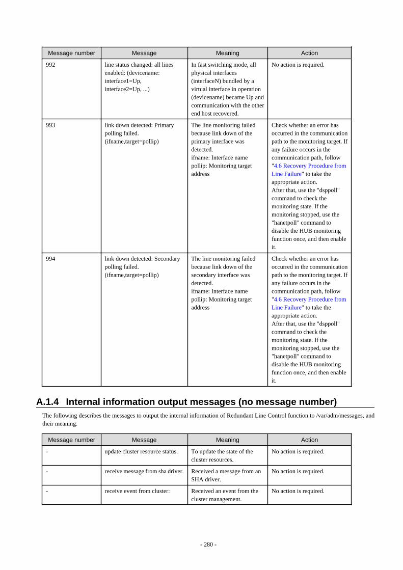
Message number Message Meaning Action
992 line status changed: all linesenabled: (devicename:interface1=Up,interface2=Up, ...)
In fast switching mode, allphysical interfaces(interfaceN) bundled by avirtual interface in operation(devicename) became Up andcommunication with the otherend host recovered.
No action is required.
993 link down detected: Primarypolling failed.(ifname,target=pollip)
The line monitoring failedbecause link down of theprimary interface wasdetected.ifname: Interface namepollip: Monitoring targetaddress
Check whether an error hasoccurred in the communicationpath to the monitoring target. Ifany failure occurs in thecommunication path, follow"4.6 Recovery Procedure fromLine Failure" to take theappropriate action.After that, use the "dsppoll"command to check themonitoring state. If themonitoring stopped, use the"hanetpoll" command todisable the HUB monitoringfunction once, and then enableit.
994 link down detected: Secondarypolling failed.(ifname,target=pollip)
The line monitoring failedbecause link down of thesecondary interface wasdetected.ifname: Interface namepollip: Monitoring targetaddress
Check whether an error hasoccurred in the communicationpath to the monitoring target. Ifany failure occurs in thecommunication path, follow"4.6 Recovery Procedure fromLine Failure" to take theappropriate action.After that, use the "dsppoll"command to check themonitoring state. If themonitoring stopped, use the"hanetpoll" command todisable the HUB monitoringfunction once, and then enableit.
A.1.4 Internal information output messages (no message number)The following describes the messages to output the internal information of Redundant Line Control function to /var/adm/messages, andtheir meaning.
Message number Message Meaning Action
- update cluster resource status. To update the state of thecluster resources.
No action is required.
- receive message from sha driver. Received a message from anSHA driver.
No action is required.
- receive event from cluster: Received an event from thecluster management.
No action is required.
- 280 -

Message number Message Meaning Action
- polling To control a monitoringfunction.
No action is required.
- in.routed killed. To terminate an in.routeddaemon process.
No action is required.
- in.rdisc killed. To terminate an in.rdiscdaemon process.
No action is required.
- child proc exit. A monitoring processterminated.
No action is required.
A.1.5 DR connection script error output messagesIn a DR connection script of the Redundant Line Control function, a message is output when not possible to continue communication bydisconnecting the corresponding virtual interface and the actual interface due to a certain reason, or when failed to disconnect or connectdetecting an error in the workings of a DR connection script. The messages displayed in a DR connection script of the Redundant LineControl function are as follows:
Code Message Meaning Action
0001 When the DR processing isexecuted for this NIC, thecommunication is disconnected.The DR processing is stopped.devicename=XX interface=YY
When executed a DR processto an interface YY that avirtual interface XX bundles,the communication isdisconnected. Stops the DRprocess.
Deactivate a virtual interfaceXX, delete a definition of avirtual interface XX, andexecute a DR process again.
0002 The interface is Cluster interface.The DR processing is stopped.action=ZZ devicename=XXinterface=YY
A virtual interface XX thatbundles an interface YY isalready registered as thecluster resource. Stops a DRprocess.
Delete a definition of the clusterenvironment and execute a DRprocess again.
0003 hanetnic command abnormalend.action=ZZ devicename=XXinterface=YY
Ended abnormally by ahanetnic command (ZZsubcommand) while having aDR process to an interface YYthat is bundled into a virtualinterface XX.
Check that there is no mistakein the setting of Redundant LineControl function. Afterchecked there is no mistake,execute a DR process again. Ifthe same phenomenon occurs,contact field engineers to reportthe error message.
0004 strptl command abnormal end.devicename=XX interface=YY
Ended abnormally by an strptlcommand while executing aDR process to an interface YYthat is bundled into a virtualinterface XX.
Check that there is no mistakein the setting of Redundant LineControl function. Afterchecked there is no mistake,execute a strptl commandagain. If the same phenomenonoccurs, contact field engineersto report the error message.
0005 stpptl command abnormal end.devicename=XX interface=YY
Ended abnormally by an stpptlcommand while executing aDR process to an interface YYthat is bundled into a virtualinterface XX.
Check that there is no mistakein the setting of Redundant LineControl function. Afterchecked there is no mistake,execute a DR process again. Ifthe same phenomenon occurs,contact field engineers to reportthe error message.
- 281 -
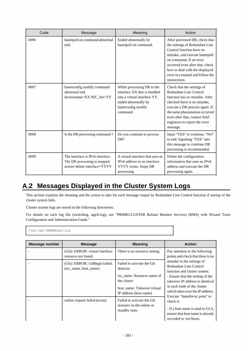
Code Message Meaning Action
0006 hanetpoll on command abnormalend.
Ended abnormally byhanetpoll on command.
After processed DR, check thatthe settings of Redundant LineControl function have nomistake, and execute hanetpollon command. If an erroroccurred even after that, checkhow to deal with the displayederror in a manual and follow theinstructions.
0007 hanetconfig modify commandabnormal end.devicename=XX NIC_list=YY
While processing DR to theinterface XX that is bundledinto a virtual interface YY,ended abnormally byhanetconfig modifycommand.
Check that the settings ofRedundant Line Controlfunction has no mistake. Afterchecked there is no mistake,execute a DR process again. Ifthe same phenomenon occurredeven after that, contact fieldengineers to report the errormessage.
0008 Is the DR processing continued ? Do you continue to processDR?
Input "YES" to continue, "NO"to end. Inputting "YES" intothis message to continue DRprocessing is recommended.
0009 The interface is IPv6 interface.The DR processing is stopped.action=delete interface=YYYY
A virtual interface that uses anIPv6 address in an interfaceYYYY exists. Stops DRprocessing.
Delete the configurationinformation that uses an IPv6address and execute the DRprocessing again.
A.2 Messages Displayed in the Cluster System LogsThis section explains the meaning and the action to take for each message output by Redundant Line Control function if startup of thecluster system fails.
Cluster system logs are stored in the following directories:
For details on each log file (switchlog, appX.log), see "PRIMECLUSTER Reliant Monitor Services (RMS) with Wizard ToolsConfiguration and Administration Guide."
/var/opt/SMAWRrms/log
Message number Message Meaning Action
- (Gls): ERROR: virtual interfaceresource not found.
There is no resource setting. Pay attention to the followingpoints and check that there is nomistake in the settings ofRedundant Line Controlfunction and cluster system.- Ensure that the setting of thetakeover IP address is identicalin each node of the clusterwhich takes over the IP address.Execute "hanethvrsc print" tocheck it.
- If a host name is used in GLS,ensure that host name is alreadyrecorded in /etc/hosts.
- (Gls): ERROR: GdBegin failed.(rsc_name, host_name)
Failed to activate the Glsdetector.
rsc_name: Resource name ofthe cluster
host_name: Takeover virtualIP address (host name)
- online request failed.(errno) Failed to activate the Glsresource in the online orstandby state.
- 282 -
Message number Message Meaning Action
19: An appropriate is notrecognized by GLS.
203: Failed to activate thetakeover virtual interface.
- Ensure that the IP addresssetting of RMS Wizard isidentical to that of the GLStakeover IP address.
If those settings are not correct,see the following sections toconfigure the settings correctly.After that, reboot the system orexecute resethanet -s.
"3.3 Additional system setup"
"3.4 Changing system setup"
"3.5 Deleting configurationinformation"
"5.2 Adding configuration forCluster System"
If those settings are correct orthe same phenomenon stilloccurs after configuring thesettings, collect materials forexamination of Redundant LineControl function and clustersystem, and then contact fieldengineers to report the errormessage.
- 283 -
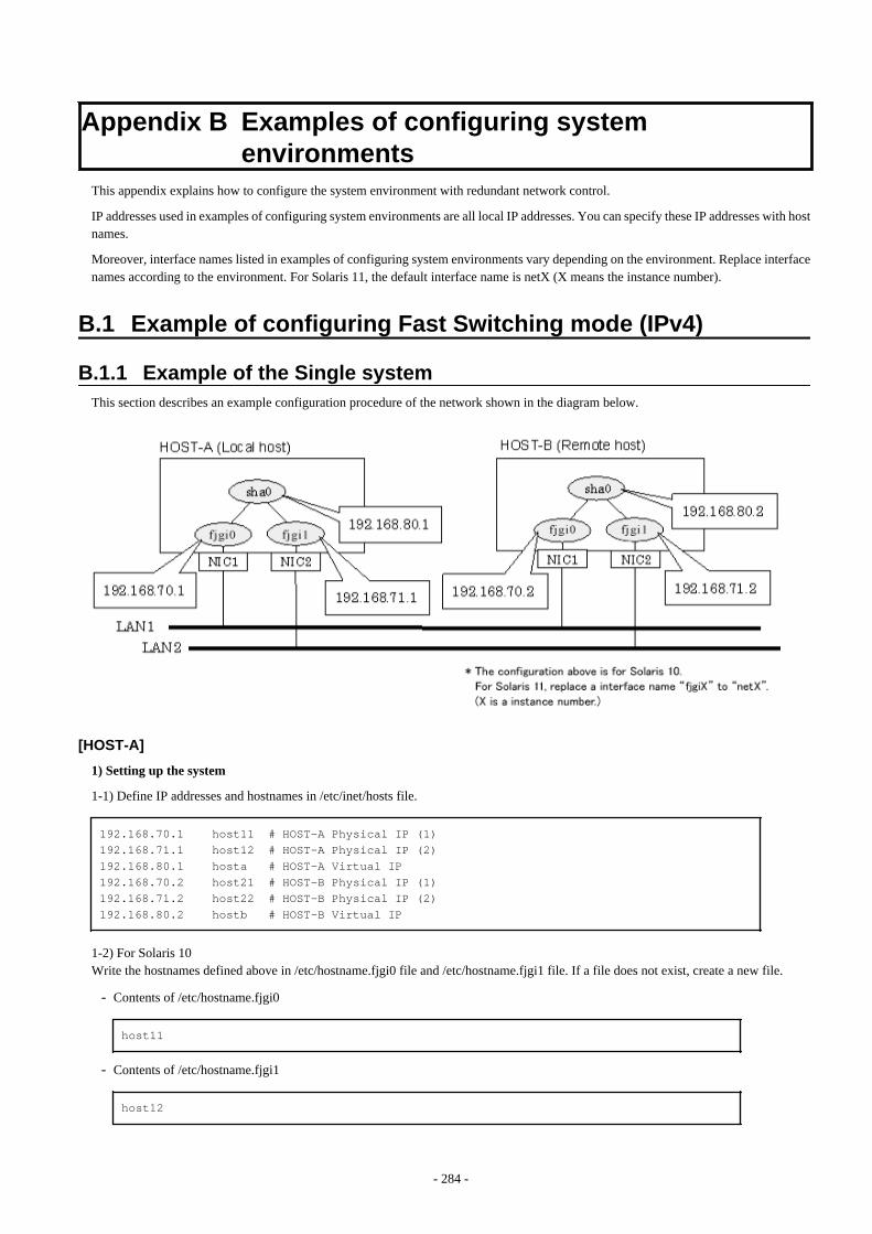
Appendix B Examples of configuring systemenvironments
This appendix explains how to configure the system environment with redundant network control.
IP addresses used in examples of configuring system environments are all local IP addresses. You can specify these IP addresses with hostnames.
Moreover, interface names listed in examples of configuring system environments vary depending on the environment. Replace interfacenames according to the environment. For Solaris 11, the default interface name is netX (X means the instance number).
B.1 Example of configuring Fast Switching mode (IPv4)
B.1.1 Example of the Single systemThis section describes an example configuration procedure of the network shown in the diagram below.
[HOST-A]
1) Setting up the system
1-1) Define IP addresses and hostnames in /etc/inet/hosts file.
192.168.70.1 host11 # HOST-A Physical IP (1)192.168.71.1 host12 # HOST-A Physical IP (2)192.168.80.1 hosta # HOST-A Virtual IP192.168.70.2 host21 # HOST-B Physical IP (1)192.168.71.2 host22 # HOST-B Physical IP (2)192.168.80.2 hostb # HOST-B Virtual IP
1-2) For Solaris 10Write the hostnames defined above in /etc/hostname.fjgi0 file and /etc/hostname.fjgi1 file. If a file does not exist, create a new file.
- Contents of /etc/hostname.fjgi0
host11
- Contents of /etc/hostname.fjgi1
host12
- 284 -
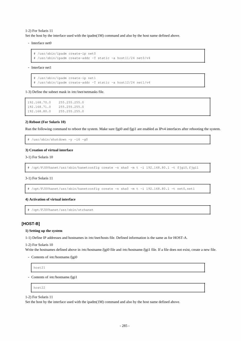
1-2) For Solaris 11Set the host by the interface used with the ipadm(1M) command and also by the host name defined above.
- Interface net0
# /usr/sbin/ipadm create-ip net0# /usr/sbin/ipadm create-addr -T static -a host11/24 net0/v4
- Interface net1
# /usr/sbin/ipadm create-ip net1# /usr/sbin/ipadm create-addr -T static -a host12/24 net1/v4
1-3) Define the subnet mask in /etc/inet/netmasks file.
192.168.70.0 255.255.255.0192.168.71.0 255.255.255.0192.168.80.0 255.255.255.0
2) Reboot (For Solaris 10)
Run the following command to reboot the system. Make sure fjgi0 and fjgi1 are enabled as IPv4 interfaces after rebooting the system.
# /usr/sbin/shutdown -y -i6 -g0
3) Creation of virtual interface
3-1) For Solaris 10
# /opt/FJSVhanet/usr/sbin/hanetconfig create -n sha0 -m t -i 192.168.80.1 -t fjgi0,fjgi1
3-1) For Solaris 11
# /opt/FJSVhanet/usr/sbin/hanetconfig create -n sha0 -m t -i 192.168.80.1 -t net0,net1
4) Activation of virtual interface
# /opt/FJSVhanet/usr/sbin/strhanet
[HOST-B]
1) Setting up the system
1-1) Define IP addresses and hostnames in /etc/inet/hosts file. Defined information is the same as for HOST-A.
1-2) For Solaris 10Write the hostnames defined above in /etc/hostname.fjgi0 file and /etc/hostname.fjgi1 file. If a file does not exist, create a new file.
- Contents of /etc/hostname.fjgi0
host21
- Contents of /etc/hostname.fjgi1
host22
1-2) For Solaris 11Set the host by the interface used with the ipadm(1M) command and also by the host name defined above.
- 285 -
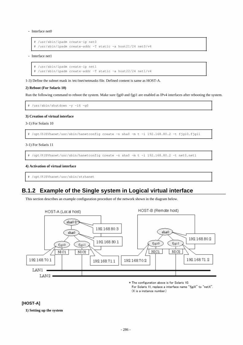
- Interface net0
# /usr/sbin/ipadm create-ip net0# /usr/sbin/ipadm create-addr -T static -a host21/24 net0/v4
- Interface net1
# /usr/sbin/ipadm create-ip net1# /usr/sbin/ipadm create-addr -T static -a host22/24 net1/v4
1-3) Define the subnet mask in /etc/inet/netmasks file. Defined content is same as HOST-A.
2) Reboot (For Solaris 10)
Run the following command to reboot the system. Make sure fjgi0 and fjgi1 are enabled as IPv4 interfaces after rebooting the system.
# /usr/sbin/shutdown -y -i6 -g0
3) Creation of virtual interface
3-1) For Solaris 10
# /opt/FJSVhanet/usr/sbin/hanetconfig create -n sha0 -m t -i 192.168.80.2 -t fjgi0,fjgi1
3-1) For Solaris 11
# /opt/FJSVhanet/usr/sbin/hanetconfig create -n sha0 -m t -i 192.168.80.2 -t net0,net1
4) Activation of virtual interface
# /opt/FJSVhanet/usr/sbin/strhanet
B.1.2 Example of the Single system in Logical virtual interfaceThis section describes an example configuration procedure of the network shown in the diagram below.
[HOST-A]
1) Setting up the system
- 286 -
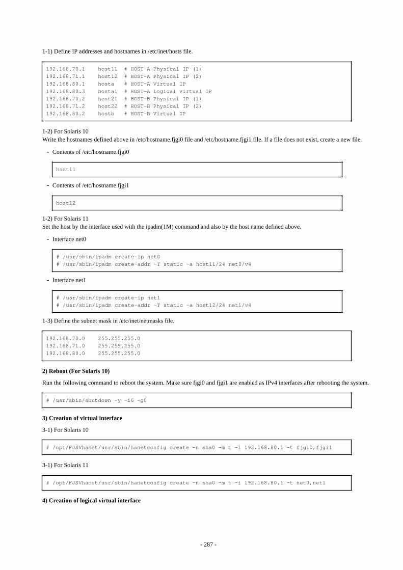
1-1) Define IP addresses and hostnames in /etc/inet/hosts file.
192.168.70.1 host11 # HOST-A Physical IP (1)192.168.71.1 host12 # HOST-A Physical IP (2)192.168.80.1 hosta # HOST-A Virtual IP192.168.80.3 hosta1 # HOST-A Logical virtual IP 192.168.70.2 host21 # HOST-B Physical IP (1)192.168.71.2 host22 # HOST-B Physical IP (2)192.168.80.2 hostb # HOST-B Virtual IP
1-2) For Solaris 10Write the hostnames defined above in /etc/hostname.fjgi0 file and /etc/hostname.fjgi1 file. If a file does not exist, create a new file.
- Contents of /etc/hostname.fjgi0
host11
- Contents of /etc/hostname.fjgi1
host12
1-2) For Solaris 11Set the host by the interface used with the ipadm(1M) command and also by the host name defined above.
- Interface net0
# /usr/sbin/ipadm create-ip net0# /usr/sbin/ipadm create-addr -T static -a host11/24 net0/v4
- Interface net1
# /usr/sbin/ipadm create-ip net1# /usr/sbin/ipadm create-addr -T static -a host12/24 net1/v4
1-3) Define the subnet mask in /etc/inet/netmasks file.
192.168.70.0 255.255.255.0192.168.71.0 255.255.255.0192.168.80.0 255.255.255.0
2) Reboot (For Solaris 10)
Run the following command to reboot the system. Make sure fjgi0 and fjgi1 are enabled as IPv4 interfaces after rebooting the system.
# /usr/sbin/shutdown -y -i6 -g0
3) Creation of virtual interface
3-1) For Solaris 10
# /opt/FJSVhanet/usr/sbin/hanetconfig create -n sha0 -m t -i 192.168.80.1 -t fjgi0,fjgi1
3-1) For Solaris 11
# /opt/FJSVhanet/usr/sbin/hanetconfig create -n sha0 -m t -i 192.168.80.1 -t net0,net1
4) Creation of logical virtual interface
- 287 -

# /opt/FJSVhanet/usr/sbin/hanetconfig create -n sha0:2 -i 192.168.80.3
5) Activation of virtual interface and logical virtual interface
# /opt/FJSVhanet/usr/sbin/strhanet
[HOST-B]
1) Setting up the system
1-1) Define IP addresses and hostnames in /etc/inet/hosts file. Defined information is the same as for HOST-A.
1-2) For Solaris 10Write the hostnames defined above in /etc/hostname.fjgi0 file and /etc/hostname.fjgi1 file. If a file does not exist, create a new file.
- Contents of /etc/hostname.fjgi0
host21
- Contents of /etc/hostname.fjgi1
host22
1-2) For Solaris 11Set the host by the interface used with the ipadm(1M) command and also by the host name defined above.
- Interface net0
# /usr/sbin/ipadm create-ip net0# /usr/sbin/ipadm create-addr -T static -a host21/24 net0/v4
- Interface net1
# /usr/sbin/ipadm create-ip net1# /usr/sbin/ipadm create-addr -T static -a host22/24 net1/v4
1-3) Define the subnet mask in /etc/inet/netmasks file. Defined content is same as HOST-A.
2) Reboot (For Solaris 10)
Run the following command to reboot the system. Make sure fjgi0 and fjgi1 are enabled as IPv4 interfaces after rebooting the system.
# /usr/sbin/shutdown -y -i6 -g0
3) Creation of virtual interface
3-1) For Solaris 10
# /opt/FJSVhanet/usr/sbin/hanetconfig create -n sha0 -m t -i 192.168.80.2 -t fjgi0,fjgi1
3-1) For Solaris 11
# /opt/FJSVhanet/usr/sbin/hanetconfig create -n sha0 -m t -i 192.168.80.2 -t net0,net1
4) Activation of virtual interface
# /opt/FJSVhanet/usr/sbin/strhanet
- 288 -
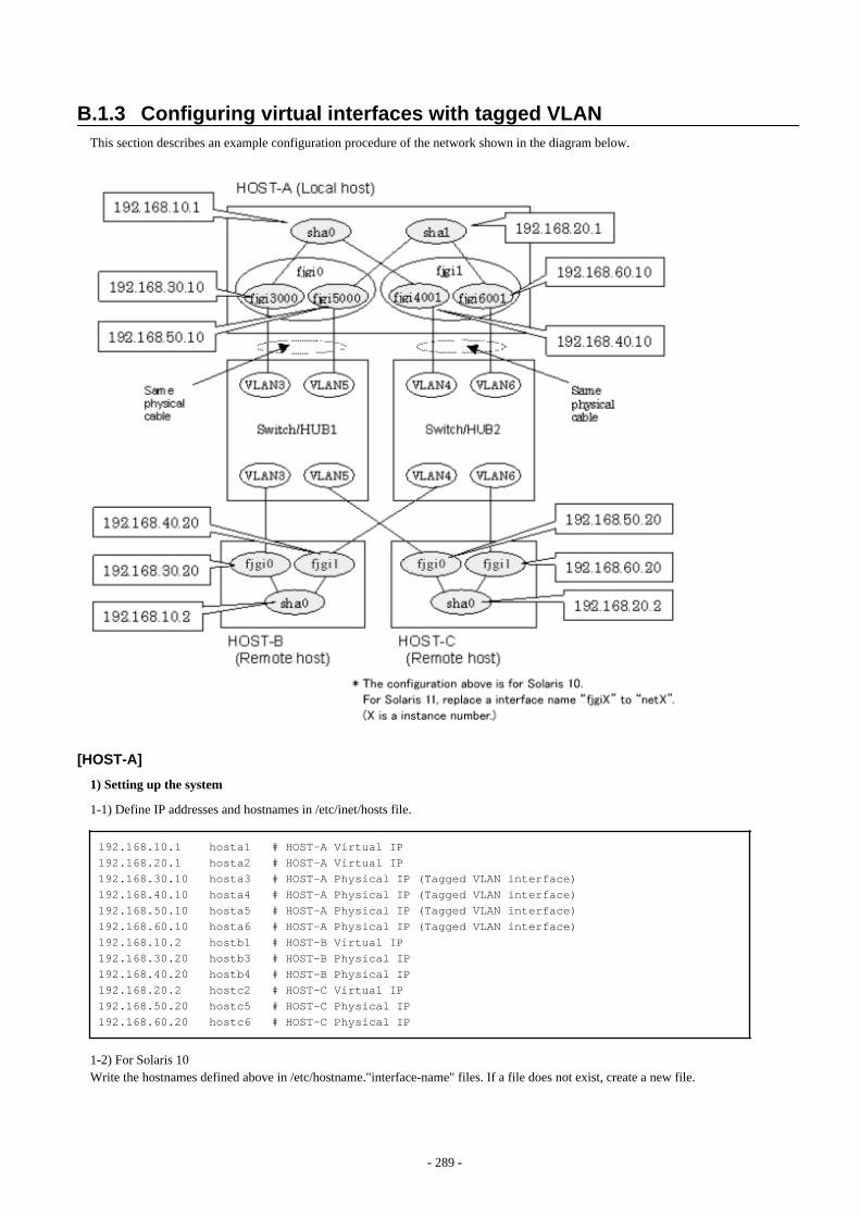
B.1.3 Configuring virtual interfaces with tagged VLANThis section describes an example configuration procedure of the network shown in the diagram below.
[HOST-A]
1) Setting up the system
1-1) Define IP addresses and hostnames in /etc/inet/hosts file.
192.168.10.1 hosta1 # HOST-A Virtual IP192.168.20.1 hosta2 # HOST-A Virtual IP192.168.30.10 hosta3 # HOST-A Physical IP (Tagged VLAN interface)192.168.40.10 hosta4 # HOST-A Physical IP (Tagged VLAN interface)192.168.50.10 hosta5 # HOST-A Physical IP (Tagged VLAN interface)192.168.60.10 hosta6 # HOST-A Physical IP (Tagged VLAN interface)192.168.10.2 hostb1 # HOST-B Virtual IP192.168.30.20 hostb3 # HOST-B Physical IP192.168.40.20 hostb4 # HOST-B Physical IP192.168.20.2 hostc2 # HOST-C Virtual IP192.168.50.20 hostc5 # HOST-C Physical IP192.168.60.20 hostc6 # HOST-C Physical IP
1-2) For Solaris 10Write the hostnames defined above in /etc/hostname."interface-name" files. If a file does not exist, create a new file.
- 289 -

- Contents of /etc/hostname.fjgi3000
hosta3
- Contents of /etc/hostname.fjgi4001
hosta4
- Contents of /etc/hostname.fjgi5000
hosta5
- Contents of /etc/hostname.fjgi6001
hosta6
1-2) For Solaris 11Set the host by the interface used with the dladm(1M) command and the ipadm(1M) command and also by the host name defined above.
- Interface net3000
# /usr/sbin/dladm create-vlan -l net0 -v 3# /usr/sbin/ipadm create-ip net3000# /usr/sbin/ipadm create-addr -T static -a hosta3/24 net3000/v4
- Interface net4001
# /usr/sbin/dladm create-vlan -l net1 -v 4# /usr/sbin/ipadm create-ip net4001# /usr/sbin/ipadm create-addr -T static -a hosta4/24 net4001/v4
- Interface net5000
# /usr/sbin/dladm create-vlan -l net0 -v 5# /usr/sbin/ipadm create-ip net5000# /usr/sbin/ipadm create-addr -T static -a hosta5/24 net5000/v4
- Interface net6001
# /usr/sbin/dladm create-vlan -l net1 -v 6# /usr/sbin/ipadm create-ip net6001# /usr/sbin/ipadm create-addr -T static -a hosta6/24 net6001/v4
1-3) Define the subnet mask in /etc/inet/netmasks file.
192.168.10.0 255.255.255.0192.168.20.0 255.255.255.0
2) Reboot (For Solaris 10)
Run the following command to reboot the system. Make sure fjgi3000, fjgi4001, fjgi5000 and fjgi6001 are enabled as IPv4 interfaces afterrebooting the system.
# /usr/sbin/shutdown -y -i6 -g0
3) Creation of virtual interface
3-1) For Solaris 10
- 290 -

# /opt/FJSVhanet/usr/sbin/hanetconfig create -n sha0 -m t -i 192.168.10.1 -t fjgi3000,fjgi4001# /opt/FJSVhanet/usr/sbin/hanetconfig create -n sha1 -m t -i 192.168.20.1 -t fjgi5000,fjgi6001
3-1) For Solaris 11
# /opt/FJSVhanet/usr/sbin/hanetconfig create -n sha0 -m t -i 192.168.10.1 -t net3000,net4001# /opt/FJSVhanet/usr/sbin/hanetconfig create -n sha1 -m t -i 192.168.20.1 -t net5000,net6001
4) Activation of virtual interface
# /opt/FJSVhanet/usr/sbin/strhanet
[HOST-B]
1) Setting up the system
1-1) Define IP addresses and hostnames in /etc/inet/hosts file. Defined information is the same as for HOST-A.
1-2) For Solaris 10Write the hostnames defined above in /etc/hostname.fjgi0 file and /etc/hostname.fjgi1 file. If a file does not exist, create a new file.
- Contents of /etc/hostname.fjgi0
hostb3
- Contents of /etc/hostname.fjgi1
hostb4
1-2) For Solaris 11Set the host by the interface used with the ipadm(1M) command and also by the host name defined above.
- Interface net0
# /usr/sbin/ipadm create-ip net0# /usr/sbin/ipadm create-addr -T static -a hostb3/24 net0/v4
- Interface net1
# /usr/sbin/ipadm create-ip net1# /usr/sbin/ipadm create-addr -T static -a hostb4/24 net1/v4
1-3) Define the subnet mask in /etc/inet/netmasks file. Defined content is same as HOST-A.
2) Reboot (For Solaris 10)
Run the following command to reboot the system. Make sure fjgi0 and fjgi1 are enabled as IPv4 interfaces after rebooting the system.
# /usr/sbin/shutdown -y -i6 -g0
3) Creation of virtual interface
3-1) For Solaris 10
# /opt/FJSVhanet/usr/sbin/hanetconfig create -n sha0 -m t -i 192.168.10.2 -t fjgi0,fjgi1
3-1) For Solaris 11
- 291 -

# /opt/FJSVhanet/usr/sbin/hanetconfig create -n sha0 -m t -i 192.168.10.2 -t net0,net1
4) Activation of virtual interface
# /opt/FJSVhanet/usr/sbin/strhanet
[HOST-C]
1) Setting up the system
1-1) Define IP addresses and hostnames in /etc/inet/hosts file. Defined information is the same as for HOST-A.
1-2) For Solaris 10Write the hostnames defined above in /etc/hostname.fjgi0 file and /etc/hostname.fjgi1 file. If a file does not exist, create a new file.
- Contents of /etc/hostname.fjgi0
hostc5
- Contents of /etc/hostname.fjgi1
hostc6
1-2) For Solaris 11Set the host by the interface used with the ipadm(1M) command and also by the host name defined above.
- Interface net0
# /usr/sbin/ipadm create-ip net0# /usr/sbin/ipadm create-addr -T static -a hostc5/24 net0/v4
- Interface net1
# /usr/sbin/ipadm create-ip net1# /usr/sbin/ipadm create-addr -T static -a hostc6/24 net1/v4
1-3) Define the subnet mask in /etc/inet/netmasks file. Defined content is same as HOST-A.
2) Reboot (For Solaris 10)
Run the following command to reboot the system. Make sure hme0 and hme1 are enabled as IPv4 interfaces after rebooting the system.
# /usr/sbin/shutdown -y -i6 -g0
3) Creation of virtual interface
3-1) For Solaris 10
# /opt/FJSVhanet/usr/sbin/hanetconfig create -n sha0 -m t -i 192.168.20.2 -t fjgi0,fjgi1
3-1) For Solaris 11
# /opt/FJSVhanet/usr/sbin/hanetconfig create -n sha0 -m t -i 192.168.20.2 -t net0,net1
4) Activation of virtual interface
# /opt/FJSVhanet/usr/sbin/strhanet
- 292 -

B.1.4 Example of the Cluster system (1:1 Standby)This section describes an example configuration procedure of the network shown in the diagram below.
For configuring the cluster system, refer to the Cluster system manual.In this section, description of private LAN is omitted. The dotted line indicates that the interface is inactive.
[HOST-A]
1) Setting up the system
1-1) Define IP addresses and hostnames in /etc/inet/hosts file.
192.168.70.1 host11 # HOST-A Physical IP (1)192.168.71.1 host12 # HOST-A Physical IP (2)192.168.80.1 hosta # HOST-A Virtual IP192.168.70.2 host21 # HOST-B Physical IP (1)192.168.71.2 host22 # HOST-B Physical IP (2)192.168.80.2 hostb # HOST-B Virtual IP192.168.80.3 hosta1 # Takeover virtual IP
1-2) For Solaris 10Write the hostnames defined above in /etc/hostname.fjgi0 file and /etc/hostname.fjgi1 file. If a file does not exist, create a new file.
- Contents of /etc/hostname.fjgi0
host11
- Contents of /etc/hostname.fjgi1
host12
- 293 -

1-2) For Solaris 11Set the host by the interface used with the ipadm(1M) command and also by the host name defined above.
- Interface net0
# /usr/sbin/ipadm create-ip net0# /usr/sbin/ipadm create-addr -T static -a host11/24 net0/v4
- Interface net1
# /usr/sbin/ipadm create-ip net1# /usr/sbin/ipadm create-addr -T static -a host12/24 net1/v4
1-3) Define the subnet mask in /etc/inet/netmasks file.
192.168.70.0 255.255.255.0192.168.71.0 255.255.255.0192.168.80.0 255.255.255.0
2) Reboot (For Solaris 10)
Run the following command to reboot the system. Make sure fjgi0 and fjgi1 are enabled as IPv4 interfaces after rebooting the system.
# /usr/sbin/shutdown -y -i6 -g0
3) Creation of virtual interface
3-1) For Solaris 10
# /opt/FJSVhanet/usr/sbin/hanetconfig create -n sha0 -m t -i 192.168.80.1 -t fjgi0,fjgi1
3-1) For Solaris 11
# /opt/FJSVhanet/usr/sbin/hanetconfig create -n sha0 -m t -i 192.168.80.1 -t net0,net1
4) Creation of takeover virtual interface
# /opt/FJSVhanet/usr/sbin/hanethvrsc create -n sha0 -i 192.168.80.3
[HOST-B]
1) Setting up the system
1-1) Define IP addresses and hostnames in /etc/inet/hosts file. Defined information is the same as for HOST-A.
1-2) For Solaris 10Write the hostnames defined above in /etc/hostname.fjgi0 file and /etc/hostname.fjgi1 file. If a file does not exist, create a new file.
- Contents of /etc/hostname.fjgi0
host21
- Contents of /etc/hostname.fjgi1
host22
1-2) For Solaris 11Set the host by the interface used with the ipadm(1M) command and also by the host name defined above.
- 294 -
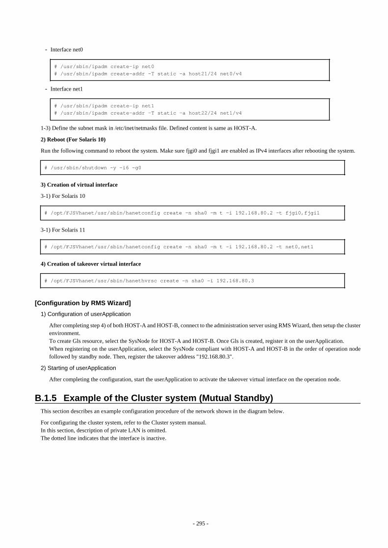
- Interface net0
# /usr/sbin/ipadm create-ip net0# /usr/sbin/ipadm create-addr -T static -a host21/24 net0/v4
- Interface net1
# /usr/sbin/ipadm create-ip net1# /usr/sbin/ipadm create-addr -T static -a host22/24 net1/v4
1-3) Define the subnet mask in /etc/inet/netmasks file. Defined content is same as HOST-A.
2) Reboot (For Solaris 10)
Run the following command to reboot the system. Make sure fjgi0 and fjgi1 are enabled as IPv4 interfaces after rebooting the system.
# /usr/sbin/shutdown -y -i6 -g0
3) Creation of virtual interface
3-1) For Solaris 10
# /opt/FJSVhanet/usr/sbin/hanetconfig create -n sha0 -m t -i 192.168.80.2 -t fjgi0,fjgi1
3-1) For Solaris 11
# /opt/FJSVhanet/usr/sbin/hanetconfig create -n sha0 -m t -i 192.168.80.2 -t net0,net1
4) Creation of takeover virtual interface
# /opt/FJSVhanet/usr/sbin/hanethvrsc create -n sha0 -i 192.168.80.3
[Configuration by RMS Wizard]
1) Configuration of userApplication
After completing step 4) of both HOST-A and HOST-B, connect to the administration server using RMS Wizard, then setup the clusterenvironment.To create Gls resource, select the SysNode for HOST-A and HOST-B. Once Gls is created, register it on the userApplication.When registering on the userApplication, select the SysNode compliant with HOST-A and HOST-B in the order of operation nodefollowed by standby node. Then, register the takeover address "192.168.80.3".
2) Starting of userApplication
After completing the configuration, start the userApplication to activate the takeover virtual interface on the operation node.
B.1.5 Example of the Cluster system (Mutual Standby)This section describes an example configuration procedure of the network shown in the diagram below.
For configuring the cluster system, refer to the Cluster system manual.In this section, description of private LAN is omitted. The dotted line indicates that the interface is inactive.
- 295 -
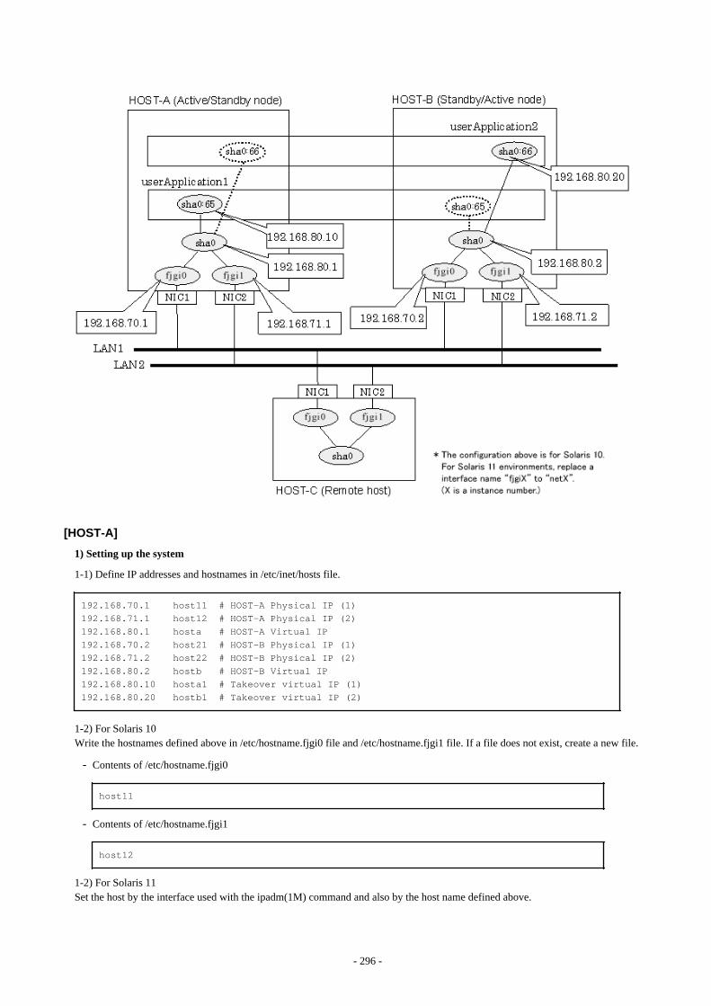
[HOST-A]
1) Setting up the system
1-1) Define IP addresses and hostnames in /etc/inet/hosts file.
192.168.70.1 host11 # HOST-A Physical IP (1)192.168.71.1 host12 # HOST-A Physical IP (2)192.168.80.1 hosta # HOST-A Virtual IP192.168.70.2 host21 # HOST-B Physical IP (1)192.168.71.2 host22 # HOST-B Physical IP (2)192.168.80.2 hostb # HOST-B Virtual IP192.168.80.10 hosta1 # Takeover virtual IP (1)192.168.80.20 hostb1 # Takeover virtual IP (2)
1-2) For Solaris 10Write the hostnames defined above in /etc/hostname.fjgi0 file and /etc/hostname.fjgi1 file. If a file does not exist, create a new file.
- Contents of /etc/hostname.fjgi0
host11
- Contents of /etc/hostname.fjgi1
host12
1-2) For Solaris 11Set the host by the interface used with the ipadm(1M) command and also by the host name defined above.
- 296 -
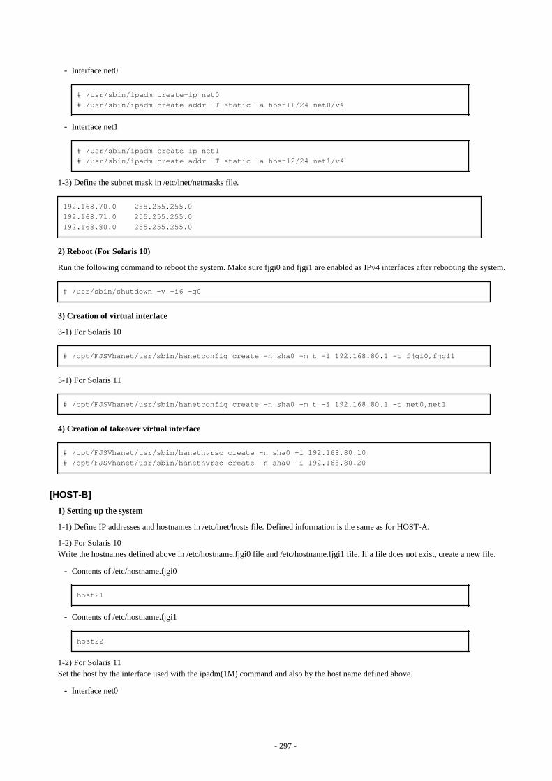
- Interface net0
# /usr/sbin/ipadm create-ip net0# /usr/sbin/ipadm create-addr -T static -a host11/24 net0/v4
- Interface net1
# /usr/sbin/ipadm create-ip net1# /usr/sbin/ipadm create-addr -T static -a host12/24 net1/v4
1-3) Define the subnet mask in /etc/inet/netmasks file.
192.168.70.0 255.255.255.0192.168.71.0 255.255.255.0192.168.80.0 255.255.255.0
2) Reboot (For Solaris 10)
Run the following command to reboot the system. Make sure fjgi0 and fjgi1 are enabled as IPv4 interfaces after rebooting the system.
# /usr/sbin/shutdown -y -i6 -g0
3) Creation of virtual interface
3-1) For Solaris 10
# /opt/FJSVhanet/usr/sbin/hanetconfig create -n sha0 -m t -i 192.168.80.1 -t fjgi0,fjgi1
3-1) For Solaris 11
# /opt/FJSVhanet/usr/sbin/hanetconfig create -n sha0 -m t -i 192.168.80.1 -t net0,net1
4) Creation of takeover virtual interface
# /opt/FJSVhanet/usr/sbin/hanethvrsc create -n sha0 -i 192.168.80.10# /opt/FJSVhanet/usr/sbin/hanethvrsc create -n sha0 -i 192.168.80.20
[HOST-B]
1) Setting up the system
1-1) Define IP addresses and hostnames in /etc/inet/hosts file. Defined information is the same as for HOST-A.
1-2) For Solaris 10Write the hostnames defined above in /etc/hostname.fjgi0 file and /etc/hostname.fjgi1 file. If a file does not exist, create a new file.
- Contents of /etc/hostname.fjgi0
host21
- Contents of /etc/hostname.fjgi1
host22
1-2) For Solaris 11Set the host by the interface used with the ipadm(1M) command and also by the host name defined above.
- Interface net0
- 297 -
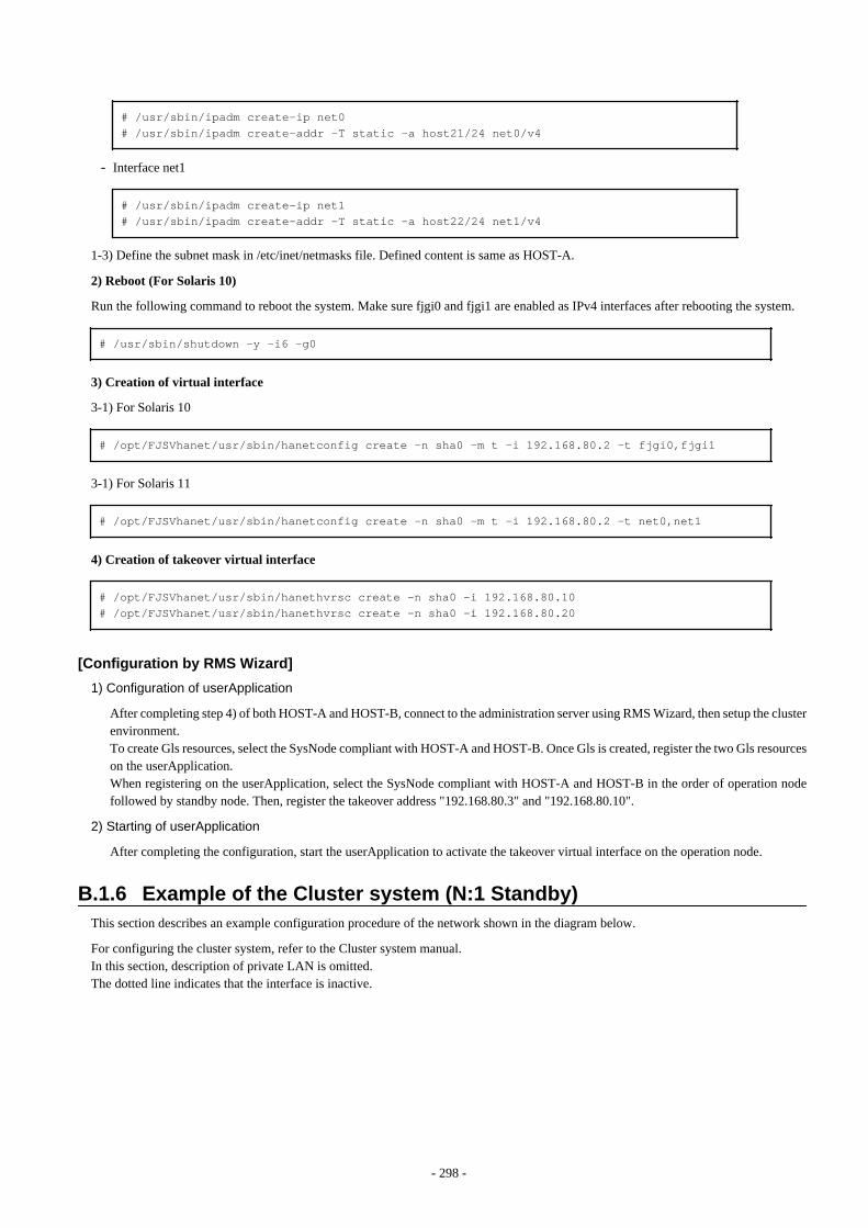
# /usr/sbin/ipadm create-ip net0# /usr/sbin/ipadm create-addr -T static -a host21/24 net0/v4
- Interface net1
# /usr/sbin/ipadm create-ip net1# /usr/sbin/ipadm create-addr -T static -a host22/24 net1/v4
1-3) Define the subnet mask in /etc/inet/netmasks file. Defined content is same as HOST-A.
2) Reboot (For Solaris 10)
Run the following command to reboot the system. Make sure fjgi0 and fjgi1 are enabled as IPv4 interfaces after rebooting the system.
# /usr/sbin/shutdown -y -i6 -g0
3) Creation of virtual interface
3-1) For Solaris 10
# /opt/FJSVhanet/usr/sbin/hanetconfig create -n sha0 -m t -i 192.168.80.2 -t fjgi0,fjgi1
3-1) For Solaris 11
# /opt/FJSVhanet/usr/sbin/hanetconfig create -n sha0 -m t -i 192.168.80.2 -t net0,net1
4) Creation of takeover virtual interface
# /opt/FJSVhanet/usr/sbin/hanethvrsc create -n sha0 -i 192.168.80.10# /opt/FJSVhanet/usr/sbin/hanethvrsc create -n sha0 -i 192.168.80.20
[Configuration by RMS Wizard]
1) Configuration of userApplication
After completing step 4) of both HOST-A and HOST-B, connect to the administration server using RMS Wizard, then setup the clusterenvironment.To create Gls resources, select the SysNode compliant with HOST-A and HOST-B. Once Gls is created, register the two Gls resourceson the userApplication.When registering on the userApplication, select the SysNode compliant with HOST-A and HOST-B in the order of operation nodefollowed by standby node. Then, register the takeover address "192.168.80.3" and "192.168.80.10".
2) Starting of userApplication
After completing the configuration, start the userApplication to activate the takeover virtual interface on the operation node.
B.1.6 Example of the Cluster system (N:1 Standby)This section describes an example configuration procedure of the network shown in the diagram below.
For configuring the cluster system, refer to the Cluster system manual.In this section, description of private LAN is omitted. The dotted line indicates that the interface is inactive.
- 298 -
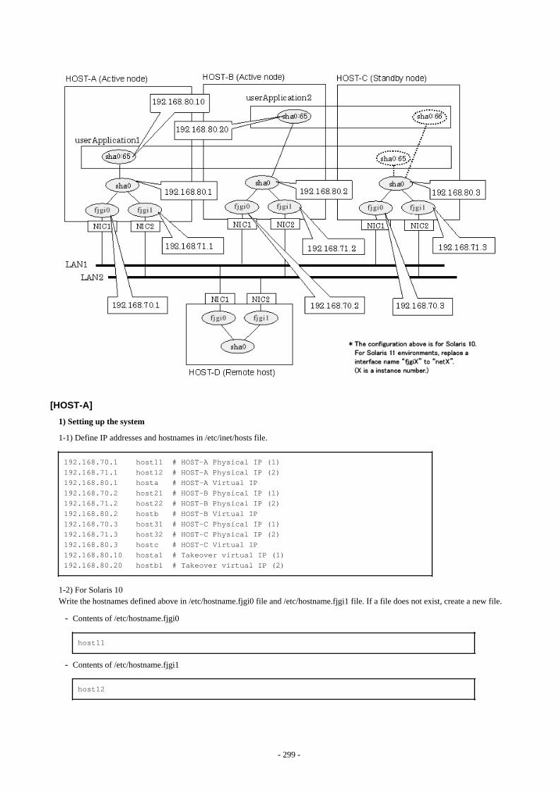
[HOST-A]
1) Setting up the system
1-1) Define IP addresses and hostnames in /etc/inet/hosts file.
192.168.70.1 host11 # HOST-A Physical IP (1)192.168.71.1 host12 # HOST-A Physical IP (2)192.168.80.1 hosta # HOST-A Virtual IP192.168.70.2 host21 # HOST-B Physical IP (1)192.168.71.2 host22 # HOST-B Physical IP (2)192.168.80.2 hostb # HOST-B Virtual IP192.168.70.3 host31 # HOST-C Physical IP (1)192.168.71.3 host32 # HOST-C Physical IP (2)192.168.80.3 hostc # HOST-C Virtual IP192.168.80.10 hosta1 # Takeover virtual IP (1)192.168.80.20 hostb1 # Takeover virtual IP (2)
1-2) For Solaris 10Write the hostnames defined above in /etc/hostname.fjgi0 file and /etc/hostname.fjgi1 file. If a file does not exist, create a new file.
- Contents of /etc/hostname.fjgi0
host11
- Contents of /etc/hostname.fjgi1
host12
- 299 -

1-2) For Solaris 11Set the host by the interface used with the ipadm(1M) command and also by the host name defined above.
- Interface net0
# /usr/sbin/ipadm create-ip net0# /usr/sbin/ipadm create-addr -T static -a host11/24 net0/v4
- Interface net1
# /usr/sbin/ipadm create-ip net1# /usr/sbin/ipadm create-addr -T static -a host12/24 net1/v4
1-3) Define the subnet mask in /etc/inet/netmasks file.
192.168.70.0 255.255.255.0192.168.71.0 255.255.255.0192.168.80.0 255.255.255.0
2) Reboot (For Solaris 10)
Run the following command to reboot the system. Make sure fjgi0 and fjgi1 are enabled as IPv4 interfaces after rebooting the system.
# /usr/sbin/shutdown -y -i6 -g0
3) Creation of virtual interface
3-1) For Solaris 10
# /opt/FJSVhanet/usr/sbin/hanetconfig create -n sha0 -m t -i 192.168.80.1 -t fjgi0,fjgi1
3-1) For Solaris 11
# /opt/FJSVhanet/usr/sbin/hanetconfig create -n sha0 -m t -i 192.168.80.1 -t net0,net1
4) Creation of takeover virtual interface
# /opt/FJSVhanet/usr/sbin/hanethvrsc create -n sha0 -i 192.168.80.10
[HOST-B]
1) Setting up the system
1-1) Define IP addresses and hostnames in /etc/inet/hosts file. Defined information is the same as for HOST-A.
1-2) For Solaris 10Write the hostnames defined above in /etc/hostname.fjgi0 file and /etc/hostname.fjgi1 file. If a file does not exist, create a new file.
- Contents of /etc/hostname.fjgi0
host21
- Contents of /etc/hostname.fjgi1
host22
1-2) For Solaris 11Set the host by the interface used with the ipadm(1M) command and also by the host name defined above.
- 300 -

- Interface net0
# /usr/sbin/ipadm create-ip net0# /usr/sbin/ipadm create-addr -T static -a host21/24 net0/v4
- Interface net1
# /usr/sbin/ipadm create-ip net1# /usr/sbin/ipadm create-addr -T static -a host22/24 net1/v4
1-3) Define the subnet mask in /etc/inet/netmasks file. Defined content is same as HOST-A.
2) Reboot (For Solaris 10)
Run the following command to reboot the system. Make sure fjgi0 and fjgi1 are enabled as IPv4 interfaces after rebooting the system.
# /usr/sbin/shutdown -y -i6 -g0
3) Creation of virtual interface
3-1) For Solaris 10
# /opt/FJSVhanet/usr/sbin/hanetconfig create -n sha0 -m t -i 192.168.80.2 -t fjgi0,fjgi1
3-1) For Solaris 11
# /opt/FJSVhanet/usr/sbin/hanetconfig create -n sha0 -m t -i 192.168.80.2 -t net0,net1
4) Creation of takeover virtual interface
# /opt/FJSVhanet/usr/sbin/hanethvrsc create -n sha0 -i 192.168.80.20
[HOST-C]
1) Setting up the system
1-1) Define IP addresses and hostnames in /etc/inet/hosts file. Defined information is the same as for HOST-A.
1-2) For Solaris 10Write the hostnames defined above in /etc/hostname.fjgi0 file and /etc/hostname.fjgi1 file. If a file does not exist, create a new file.
- Contents of /etc/hostname.fjgi0
host31
- Contents of /etc/hostname.fjgi1
host32
1-2) For Solaris 11Set the host by the interface used with the ipadm(1M) command and also by the host name defined above.
- Interface net0
# /usr/sbin/ipadm create-ip net0# /usr/sbin/ipadm create-addr -T static -a host31/24 net0/v4
- Interface net1
- 301 -
# /usr/sbin/ipadm create-ip net1# /usr/sbin/ipadm create-addr -T static -a host32/24 net1/v4
1-3) Define the subnet mask in /etc/inet/netmasks file. Defined content is same as HOST-A.
2) Reboot (For Solaris 10)
Run the following command to reboot the system. Make sure fjgi0 and fjgi1 are enabled as IPv4 interfaces after rebooting the system.
# /usr/sbin/shutdown -y -i6 -g0
3) Creation of virtual interface
3-1) For Solaris 10
# /opt/FJSVhanet/usr/sbin/hanetconfig create -n sha0 -m t -i 192.168.80.3 -t fjgi0,fjgi1
3-1) For Solaris 11
# /opt/FJSVhanet/usr/sbin/hanetconfig create -n sha0 -m t -i 192.168.80.3 -t net0,net1
4) Creation of takeover virtual interface
# /opt/FJSVhanet/usr/sbin/hanethvrsc create -n sha0 -i 192.168.80.10# /opt/FJSVhanet/usr/sbin/hanethvrsc create -n sha0 -i 192.168.80.20
[Configuration by RMS Wizard]
1) Configuration of userApplication
After completing step 4) of HOST-A, HOST-B, and HOST-C connect to the administration server using RMS Wizard, then setup thecluster environment.To create Gls resources, select the SysNode compliant with HOST-A, HOST-B, and HOST-C. Once Gls is created, register the twoGls resources on the userApplication.When registering on the userApplication, select the SysNode compliant with HOST-A, HOST-B, and HOST-C in the order of operationnode followed by standby node. Then, register the takeover address "192.168.80.3" and "192.168.80.10".
2) Starting of userApplication
After completing the configuration, start the userApplication to activate the takeover virtual interface on the operation node.
B.1.7 Example of the Cluster system (Cascade)This section describes an example configuration procedure of the network shown in the diagram below.
For configuring the cluster system, refer to the Cluster system manual.In this section, description of private LAN is omitted. The dotted line indicates that the interface is inactive.
- 302 -
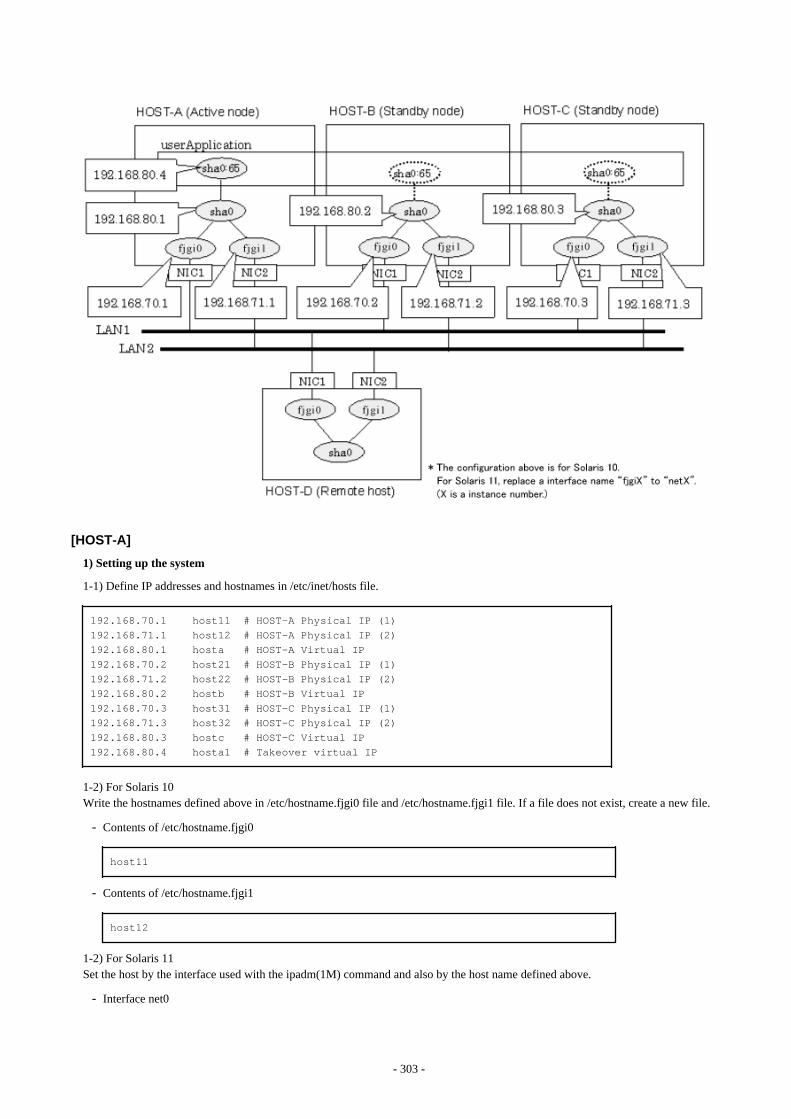
[HOST-A]
1) Setting up the system
1-1) Define IP addresses and hostnames in /etc/inet/hosts file.
192.168.70.1 host11 # HOST-A Physical IP (1)192.168.71.1 host12 # HOST-A Physical IP (2)192.168.80.1 hosta # HOST-A Virtual IP192.168.70.2 host21 # HOST-B Physical IP (1)192.168.71.2 host22 # HOST-B Physical IP (2)192.168.80.2 hostb # HOST-B Virtual IP192.168.70.3 host31 # HOST-C Physical IP (1)192.168.71.3 host32 # HOST-C Physical IP (2)192.168.80.3 hostc # HOST-C Virtual IP192.168.80.4 hosta1 # Takeover virtual IP
1-2) For Solaris 10Write the hostnames defined above in /etc/hostname.fjgi0 file and /etc/hostname.fjgi1 file. If a file does not exist, create a new file.
- Contents of /etc/hostname.fjgi0
host11
- Contents of /etc/hostname.fjgi1
host12
1-2) For Solaris 11Set the host by the interface used with the ipadm(1M) command and also by the host name defined above.
- Interface net0
- 303 -
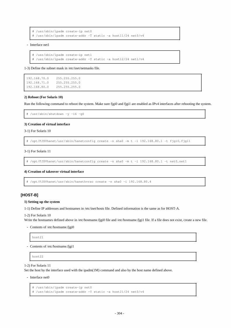
# /usr/sbin/ipadm create-ip net0# /usr/sbin/ipadm create-addr -T static -a host11/24 net0/v4
- Interface net1
# /usr/sbin/ipadm create-ip net1# /usr/sbin/ipadm create-addr -T static -a host12/24 net1/v4
1-3) Define the subnet mask in /etc/inet/netmasks file.
192.168.70.0 255.255.255.0192.168.71.0 255.255.255.0192.168.80.0 255.255.255.0
2) Reboot (For Solaris 10)
Run the following command to reboot the system. Make sure fjgi0 and fjgi1 are enabled as IPv4 interfaces after rebooting the system.
# /usr/sbin/shutdown -y -i6 -g0
3) Creation of virtual interface
3-1) For Solaris 10
# /opt/FJSVhanet/usr/sbin/hanetconfig create -n sha0 -m t -i 192.168.80.1 -t fjgi0,fjgi1
3-1) For Solaris 11
# /opt/FJSVhanet/usr/sbin/hanetconfig create -n sha0 -m t -i 192.168.80.1 -t net0,net1
4) Creation of takeover virtual interface
# /opt/FJSVhanet/usr/sbin/hanethvrsc create -n sha0 -i 192.168.80.4
[HOST-B]
1) Setting up the system
1-1) Define IP addresses and hostnames in /etc/inet/hosts file. Defined information is the same as for HOST-A.
1-2) For Solaris 10Write the hostnames defined above in /etc/hostname.fjgi0 file and /etc/hostname.fjgi1 file. If a file does not exist, create a new file.
- Contents of /etc/hostname.fjgi0
host21
- Contents of /etc/hostname.fjgi1
host22
1-2) For Solaris 11Set the host by the interface used with the ipadm(1M) command and also by the host name defined above.
- Interface net0
# /usr/sbin/ipadm create-ip net0# /usr/sbin/ipadm create-addr -T static -a host21/24 net0/v4
- 304 -

- Interface net1
# /usr/sbin/ipadm create-ip net1# /usr/sbin/ipadm create-addr -T static -a host22/24 net1/v4
1-3) Define the subnet mask in /etc/inet/netmasks file. Defined content is same as HOST-A.
2) Reboot(For Solaris 10)
Run the following command to reboot the system. Make sure fjgi0 and fjgi1 are enabled as IPv4 interfaces after rebooting the system.
# /usr/sbin/shutdown -y -i6 -g0
3) Creation of virtual interface
3-1) For Solaris 10
# /opt/FJSVhanet/usr/sbin/hanetconfig create -n sha0 -m t -i 192.168.80.2 -t fjgi0,fjgi1
3-1) For Solaris 11
# /opt/FJSVhanet/usr/sbin/hanetconfig create -n sha0 -m t -i 192.168.80.2 -t net0,net1
4) Creation of takeover virtual interface
# /opt/FJSVhanet/usr/sbin/hanethvrsc create -n sha0 -i 192.168.80.4
[HOST-C]
1) Setting up the system
1-1) Define IP addresses and hostnames in /etc/inet/hosts file. Defined information is the same as for HOST-A.
1-2) For Solaris 10Write the hostnames defined above in /etc/hostname.fjgi0 file and /etc/hostname.fjgi1 file. If a file does not exist, create a new file.
- Contents of /etc/hostname.fjgi0
host31
- Contents of /etc/hostname.fjgi1
host32
1-2) For Solaris 11Set the host by the interface used with the ipadm(1M) command and also by the host name defined above.
- Interface net0
# /usr/sbin/ipadm create-ip net0# /usr/sbin/ipadm create-addr -T static -a host31/24 net0/v4
- Interface net1
# /usr/sbin/ipadm create-ip net1# /usr/sbin/ipadm create-addr -T static -a host32/24 net1/v4
1-3) Define the subnet mask in /etc/inet/netmasks file. Defined content is same as HOST-A.
2) Reboot (For Solaris 10)
- 305 -
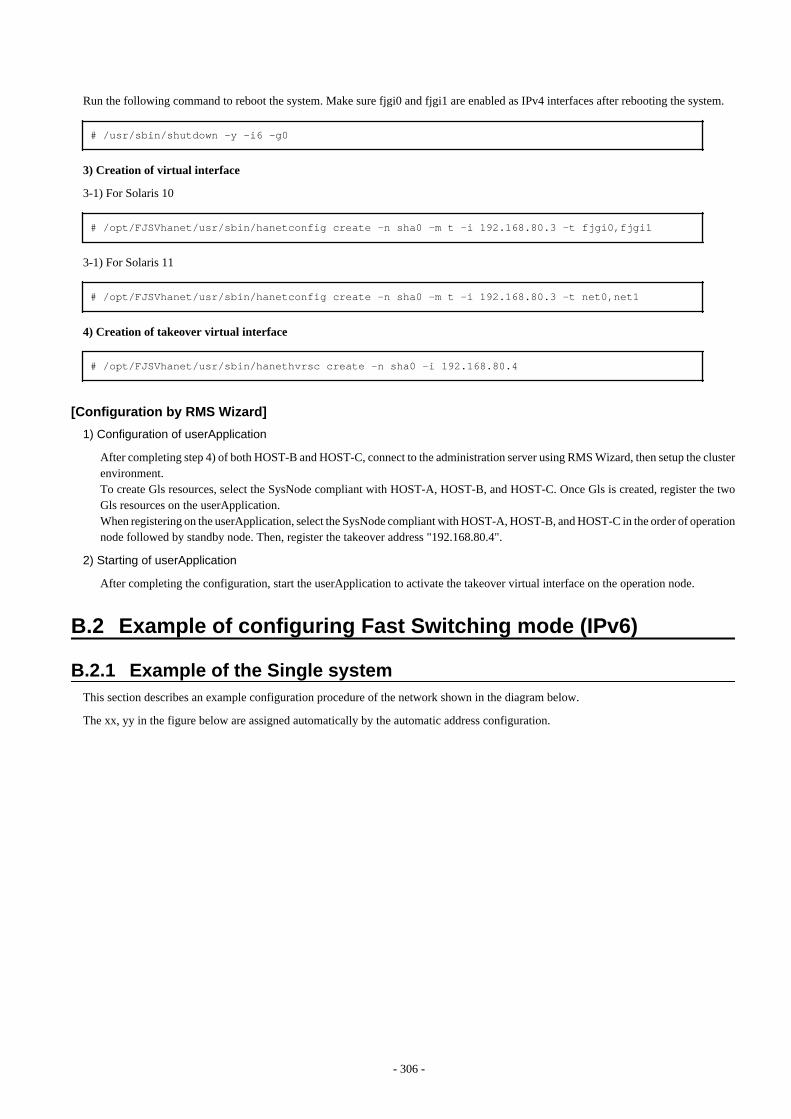
Run the following command to reboot the system. Make sure fjgi0 and fjgi1 are enabled as IPv4 interfaces after rebooting the system.
# /usr/sbin/shutdown -y -i6 -g0
3) Creation of virtual interface
3-1) For Solaris 10
# /opt/FJSVhanet/usr/sbin/hanetconfig create -n sha0 -m t -i 192.168.80.3 -t fjgi0,fjgi1
3-1) For Solaris 11
# /opt/FJSVhanet/usr/sbin/hanetconfig create -n sha0 -m t -i 192.168.80.3 -t net0,net1
4) Creation of takeover virtual interface
# /opt/FJSVhanet/usr/sbin/hanethvrsc create -n sha0 -i 192.168.80.4
[Configuration by RMS Wizard]
1) Configuration of userApplication
After completing step 4) of both HOST-B and HOST-C, connect to the administration server using RMS Wizard, then setup the clusterenvironment.To create Gls resources, select the SysNode compliant with HOST-A, HOST-B, and HOST-C. Once Gls is created, register the twoGls resources on the userApplication.When registering on the userApplication, select the SysNode compliant with HOST-A, HOST-B, and HOST-C in the order of operationnode followed by standby node. Then, register the takeover address "192.168.80.4".
2) Starting of userApplication
After completing the configuration, start the userApplication to activate the takeover virtual interface on the operation node.
B.2 Example of configuring Fast Switching mode (IPv6)
B.2.1 Example of the Single systemThis section describes an example configuration procedure of the network shown in the diagram below.
The xx, yy in the figure below are assigned automatically by the automatic address configuration.
- 306 -
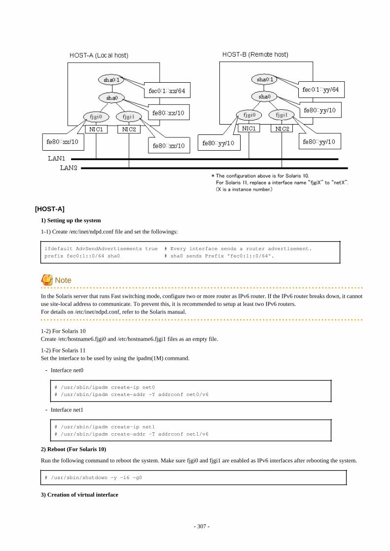
[HOST-A]
1) Setting up the system
1-1) Create /etc/inet/ndpd.conf file and set the followings:
ifdefault AdvSendAdvertisements true # Every interface sends a router advertisement.prefix fec0:1::0/64 sha0 # sha0 sends Prefix "fec0:1::0/64".
Note
In the Solaris server that runs Fast switching mode, configure two or more router as IPv6 router. If the IPv6 router breaks down, it cannotuse site-local address to communicate. To prevent this, it is recommended to setup at least two IPv6 routers.For details on /etc/inet/ndpd.conf, refer to the Solaris manual.
1-2) For Solaris 10Create /etc/hostname6.fjgi0 and /etc/hostname6.fjgi1 files as an empty file.
1-2) For Solaris 11Set the interface to be used by using the ipadm(1M) command.
- Interface net0
# /usr/sbin/ipadm create-ip net0# /usr/sbin/ipadm create-addr -T addrconf net0/v6
- Interface net1
# /usr/sbin/ipadm create-ip net1# /usr/sbin/ipadm create-addr -T addrconf net1/v6
2) Reboot (For Solaris 10)
Run the following command to reboot the system. Make sure fjgi0 and fjgi1 are enabled as IPv6 interfaces after rebooting the system.
# /usr/sbin/shutdown -y -i6 -g0
3) Creation of virtual interface
- 307 -

3-1) For Solaris 10
# /opt/FJSVhanet/usr/sbin/hanetconfig create inet6 -n sha0 -m t -t fjgi0,fjgi1
3-1) For Solaris 11
# /opt/FJSVhanet/usr/sbin/hanetconfig create inet6 -n sha0 -m t -t net0,net1
4) Activation of virtual interface
# /opt/FJSVhanet/usr/sbin/strhanet
[HOST-B]
1) Setting up the system
1-1) Create /etc/inet/ndpd.conf file. Defined information is the same as for HOST-A.
1-2) For Solaris 10Create /etc/hostname6.fjgi0 and /etc/hostname6.fjgi1 file as an empty file.
1-2) For Solaris 11Set the interface to be used by using the ipadm(1M) command.
- Interface net0
# /usr/sbin/ipadm create-ip net0# /usr/sbin/ipadm create-addr -T addrconf net0/v6
- Interface net1
# /usr/sbin/ipadm create-ip net1# /usr/sbin/ipadm create-addr -T addrconf net1/v6
2) Reboot (For Solaris 10)
Run the following command to reboot the system. Make sure fjgi0 and fjgi1 are enabled as IPv6 interfaces after rebooting the system.
# /usr/sbin/shutdown -y -i6 -g0
3) Creation of virtual interface
3-1) For Solaris 10
# /opt/FJSVhanet/usr/sbin/hanetconfig create inet6 -n sha0 -m t -t fjgi0,fjgi1
3-1) For Solaris 11
# /opt/FJSVhanet/usr/sbin/hanetconfig create inet6 -n sha0 -m t -t net0,net1
4) Activation of virtual interface
# /opt/FJSVhanet/usr/sbin/strhanet
B.2.2 Example of the Single system in Logical virtual interfaceThis section describes an example configuration procedure of the network shown in the diagram below.
The xx, yy in the figure below are assigned automatically by the automatic address configuration.
- 308 -
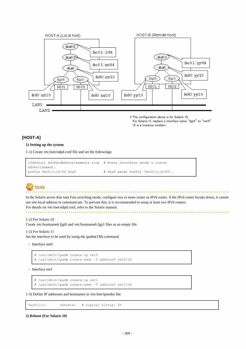
[HOST-A]
1) Setting up the system
1-1) Create /etc/inet/ndpd.conf file and set the followings:
ifdefault AdvSendAdvertisements true # Every interface sends a router advertisement.prefix fec0:1::0/64 sha0 # sha0 sends Prefix "fec0:1::0/64".
Note
In the Solaris server that runs Fast switching mode, configure two or more router as IPv6 router. If the IPv6 router breaks down, it cannotuse site-local address to communicate. To prevent this, it is recommended to setup at least two IPv6 routers.For details on /etc/inet/ndpd.conf, refer to the Solaris manual.
1-2) For Solaris 10Create /etc/hostname6.fjgi0 and /etc/hostname6.fjgi1 files as an empty file.
1-2) For Solaris 11Set the interface to be used by using the ipadm(1M) command.
- Interface net0
# /usr/sbin/ipadm create-ip net0# /usr/sbin/ipadm create-addr -T addrconf net0/v6
- Interface net1
# /usr/sbin/ipadm create-ip net1# /usr/sbin/ipadm create-addr -T addrconf net1/v6
1-3) Define IP addresses and hostnames in /etc/inet/ipnodes file.
fec0:1::1 v6hosta1 # Logical virtual IP
2) Reboot (For Solaris 10)
- 309 -
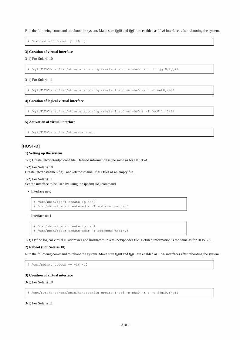
Run the following command to reboot the system. Make sure fjgi0 and fjgi1 are enabled as IPv6 interfaces after rebooting the system.
# /usr/sbin/shutdown -y -i6 -g
3) Creation of virtual interface
3-1) For Solaris 10
# /opt/FJSVhanet/usr/sbin/hanetconfig create inet6 -n sha0 -m t -t fjgi0,fjgi1
3-1) For Solaris 11
# /opt/FJSVhanet/usr/sbin/hanetconfig create inet6 -n sha0 -m t -t net0,net1
4) Creation of logical virtual interface
# /opt/FJSVhanet/usr/sbin/hanetconfig create inet6 -n sha0:2 -i fec0:1::1/64
5) Activation of virtual interface
# /opt/FJSVhanet/usr/sbin/strhanet
[HOST-B]
1) Setting up the system
1-1) Create /etc/inet/ndpd.conf file. Defined information is the same as for HOST-A.
1-2) For Solaris 10Create /etc/hostname6.fjgi0 and /etc/hostname6.fjgi1 files as an empty file.
1-2) For Solaris 11Set the interface to be used by using the ipadm(1M) command.
- Interface net0
# /usr/sbin/ipadm create-ip net0# /usr/sbin/ipadm create-addr -T addrconf net0/v6
- Interface net1
# /usr/sbin/ipadm create-ip net1# /usr/sbin/ipadm create-addr -T addrconf net1/v6
1-3) Define logical virtual IP addresses and hostnames in /etc/inet/ipnodes file. Defined information is the same as for HOST-A.
2) Reboot (For Solaris 10)
Run the following command to reboot the system. Make sure fjgi0 and fjgi1 are enabled as IPv6 interfaces after rebooting the system.
# /usr/sbin/shutdown -y -i6 -g0
3) Creation of virtual interface
3-1) For Solaris 10
# /opt/FJSVhanet/usr/sbin/hanetconfig create inet6 -n sha0 -m t -t fjgi0,fjgi1
3-1) For Solaris 11
- 310 -
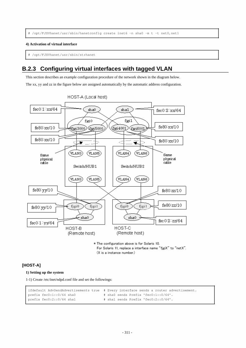
# /opt/FJSVhanet/usr/sbin/hanetconfig create inet6 -n sha0 -m t -t net0,net1
4) Activation of virtual interface
# /opt/FJSVhanet/usr/sbin/strhanet
B.2.3 Configuring virtual interfaces with tagged VLANThis section describes an example configuration procedure of the network shown in the diagram below.
The xx, yy and zz in the figure below are assigned automatically by the automatic address configuration.
[HOST-A]
1) Setting up the system
1-1) Create /etc/inet/ndpd.conf file and set the followings:
ifdefault AdvSendAdvertisements true # Every interface sends a router advertisement.prefix fec0:1::0/64 sha0 # sha0 sends Prefix "fec0:1::0/64".prefix fec0:2::0/64 sha1 # sha1 sends Prefix "fec0:2::0/64".
- 311 -
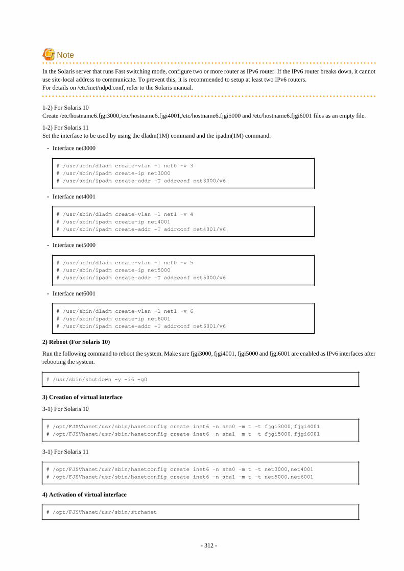
Note
In the Solaris server that runs Fast switching mode, configure two or more router as IPv6 router. If the IPv6 router breaks down, it cannotuse site-local address to communicate. To prevent this, it is recommended to setup at least two IPv6 routers.For details on /etc/inet/ndpd.conf, refer to the Solaris manual.
1-2) For Solaris 10Create /etc/hostname6.fjgi3000,/etc/hostname6.fjgi4001,/etc/hostname6.fjgi5000 and /etc/hostname6.fjgi6001 files as an empty file.
1-2) For Solaris 11Set the interface to be used by using the dladm(1M) command and the ipadm(1M) command.
- Interface net3000
# /usr/sbin/dladm create-vlan -l net0 -v 3# /usr/sbin/ipadm create-ip net3000# /usr/sbin/ipadm create-addr -T addrconf net3000/v6
- Interface net4001
# /usr/sbin/dladm create-vlan -l net1 -v 4# /usr/sbin/ipadm create-ip net4001# /usr/sbin/ipadm create-addr -T addrconf net4001/v6
- Interface net5000
# /usr/sbin/dladm create-vlan -l net0 -v 5# /usr/sbin/ipadm create-ip net5000# /usr/sbin/ipadm create-addr -T addrconf net5000/v6
- Interface net6001
# /usr/sbin/dladm create-vlan -l net1 -v 6# /usr/sbin/ipadm create-ip net6001# /usr/sbin/ipadm create-addr -T addrconf net6001/v6
2) Reboot (For Solaris 10)
Run the following command to reboot the system. Make sure fjgi3000, fjgi4001, fjgi5000 and fjgi6001 are enabled as IPv6 interfaces afterrebooting the system.
# /usr/sbin/shutdown -y -i6 -g0
3) Creation of virtual interface
3-1) For Solaris 10
# /opt/FJSVhanet/usr/sbin/hanetconfig create inet6 -n sha0 -m t -t fjgi3000,fjgi4001# /opt/FJSVhanet/usr/sbin/hanetconfig create inet6 -n sha1 -m t -t fjgi5000,fjgi6001
3-1) For Solaris 11
# /opt/FJSVhanet/usr/sbin/hanetconfig create inet6 -n sha0 -m t -t net3000,net4001# /opt/FJSVhanet/usr/sbin/hanetconfig create inet6 -n sha1 -m t -t net5000,net6001
4) Activation of virtual interface
# /opt/FJSVhanet/usr/sbin/strhanet
- 312 -
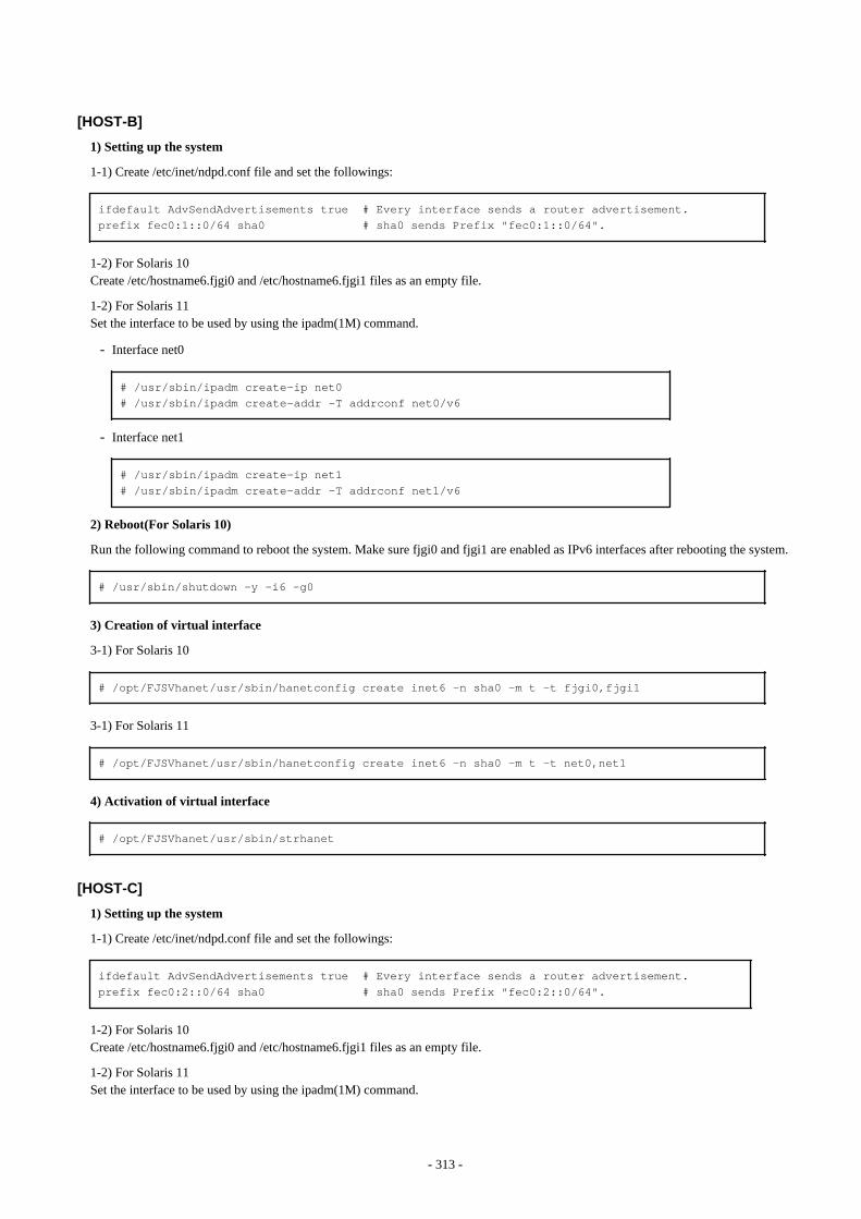
[HOST-B]
1) Setting up the system
1-1) Create /etc/inet/ndpd.conf file and set the followings:
ifdefault AdvSendAdvertisements true # Every interface sends a router advertisement.prefix fec0:1::0/64 sha0 # sha0 sends Prefix "fec0:1::0/64".
1-2) For Solaris 10Create /etc/hostname6.fjgi0 and /etc/hostname6.fjgi1 files as an empty file.
1-2) For Solaris 11Set the interface to be used by using the ipadm(1M) command.
- Interface net0
# /usr/sbin/ipadm create-ip net0# /usr/sbin/ipadm create-addr -T addrconf net0/v6
- Interface net1
# /usr/sbin/ipadm create-ip net1# /usr/sbin/ipadm create-addr -T addrconf net1/v6
2) Reboot(For Solaris 10)
Run the following command to reboot the system. Make sure fjgi0 and fjgi1 are enabled as IPv6 interfaces after rebooting the system.
# /usr/sbin/shutdown -y -i6 -g0
3) Creation of virtual interface
3-1) For Solaris 10
# /opt/FJSVhanet/usr/sbin/hanetconfig create inet6 -n sha0 -m t -t fjgi0,fjgi1
3-1) For Solaris 11
# /opt/FJSVhanet/usr/sbin/hanetconfig create inet6 -n sha0 -m t -t net0,net1
4) Activation of virtual interface
# /opt/FJSVhanet/usr/sbin/strhanet
[HOST-C]
1) Setting up the system
1-1) Create /etc/inet/ndpd.conf file and set the followings:
ifdefault AdvSendAdvertisements true # Every interface sends a router advertisement.prefix fec0:2::0/64 sha0 # sha0 sends Prefix "fec0:2::0/64".
1-2) For Solaris 10Create /etc/hostname6.fjgi0 and /etc/hostname6.fjgi1 files as an empty file.
1-2) For Solaris 11Set the interface to be used by using the ipadm(1M) command.
- 313 -
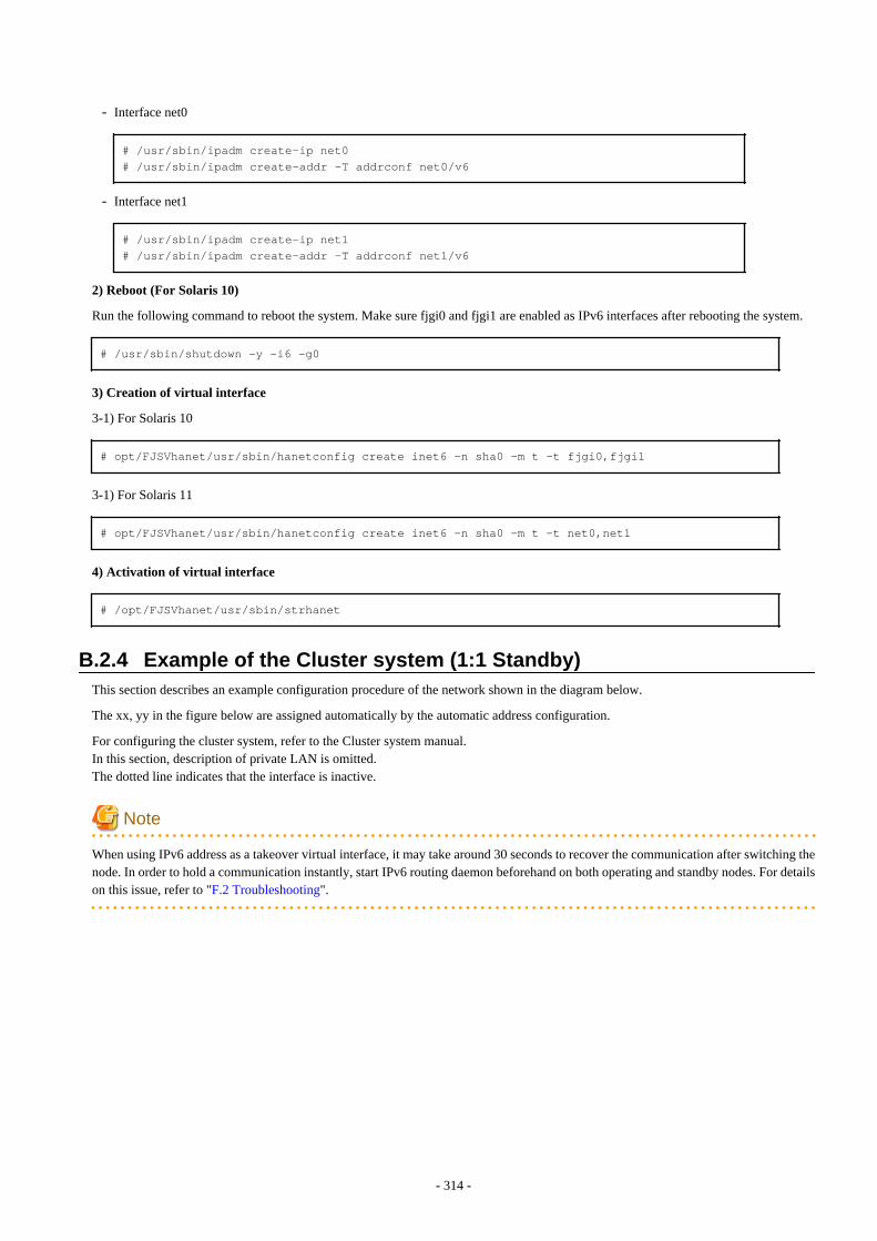
- Interface net0
# /usr/sbin/ipadm create-ip net0# /usr/sbin/ipadm create-addr -T addrconf net0/v6
- Interface net1
# /usr/sbin/ipadm create-ip net1# /usr/sbin/ipadm create-addr -T addrconf net1/v6
2) Reboot (For Solaris 10)
Run the following command to reboot the system. Make sure fjgi0 and fjgi1 are enabled as IPv6 interfaces after rebooting the system.
# /usr/sbin/shutdown -y -i6 -g0
3) Creation of virtual interface
3-1) For Solaris 10
# opt/FJSVhanet/usr/sbin/hanetconfig create inet6 -n sha0 -m t -t fjgi0,fjgi1
3-1) For Solaris 11
# opt/FJSVhanet/usr/sbin/hanetconfig create inet6 -n sha0 -m t -t net0,net1
4) Activation of virtual interface
# /opt/FJSVhanet/usr/sbin/strhanet
B.2.4 Example of the Cluster system (1:1 Standby)This section describes an example configuration procedure of the network shown in the diagram below.
The xx, yy in the figure below are assigned automatically by the automatic address configuration.
For configuring the cluster system, refer to the Cluster system manual.In this section, description of private LAN is omitted. The dotted line indicates that the interface is inactive.
Note
When using IPv6 address as a takeover virtual interface, it may take around 30 seconds to recover the communication after switching thenode. In order to hold a communication instantly, start IPv6 routing daemon beforehand on both operating and standby nodes. For detailson this issue, refer to "F.2 Troubleshooting".
- 314 -
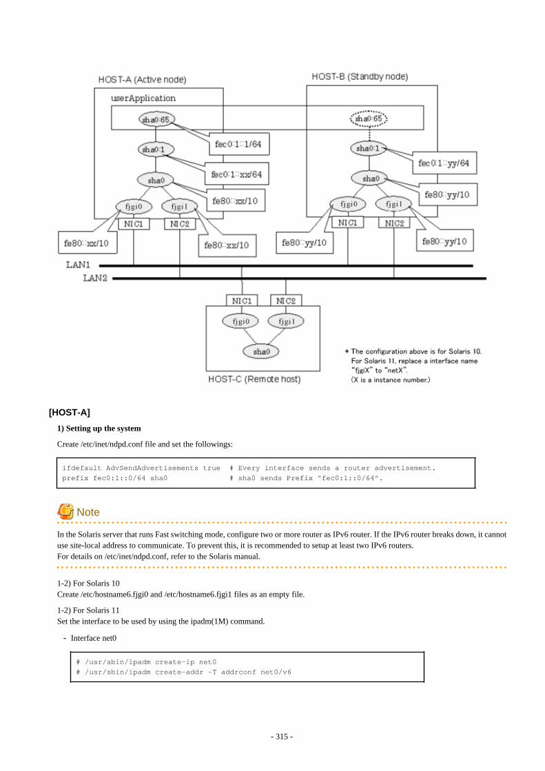
[HOST-A]
1) Setting up the system
Create /etc/inet/ndpd.conf file and set the followings:
ifdefault AdvSendAdvertisements true # Every interface sends a router advertisement.prefix fec0:1::0/64 sha0 # sha0 sends Prefix "fec0:1::0/64".
Note
In the Solaris server that runs Fast switching mode, configure two or more router as IPv6 router. If the IPv6 router breaks down, it cannotuse site-local address to communicate. To prevent this, it is recommended to setup at least two IPv6 routers.For details on /etc/inet/ndpd.conf, refer to the Solaris manual.
1-2) For Solaris 10Create /etc/hostname6.fjgi0 and /etc/hostname6.fjgi1 files as an empty file.
1-2) For Solaris 11Set the interface to be used by using the ipadm(1M) command.
- Interface net0
# /usr/sbin/ipadm create-ip net0# /usr/sbin/ipadm create-addr -T addrconf net0/v6
- 315 -
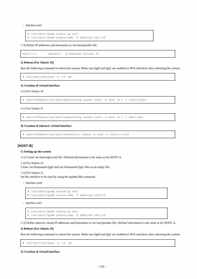
- Interface net1
# /usr/sbin/ipadm create-ip net1# /usr/sbin/ipadm create-addr -T addrconf net1/v6
1-3) Define IP addresses and hostnames in /etc/inet/ipnodes file.
fec0:1::1 v6hosta1 # Takeover virtual IP
2) Reboot (For Solaris 10)
Run the following command to reboot the system. Make sure fjgi0 and fjgi1 are enabled as IPv6 interfaces after rebooting the system.
# /usr/sbin/shutdown -y -i6 -g0
3) Creation of virtual interface
3-1) For Solaris 10
# /opt/FJSVhanet/usr/sbin/hanetconfig create inet6 -n sha0 -m t -t fjgi0,fjgi1
3-1) For Solaris 11
# /opt/FJSVhanet/usr/sbin/hanetconfig create inet6 -n sha0 -m t -t net0,net1
4) Creation of takeover virtual interface
# /opt/FJSVhanet/usr/sbin/hanethvrsc create -n sha0 -i fec0:1::1/64
[HOST-B]
1) Setting up the system
1-1) Create /etc/inet/ndpd.conf file. Defined information is the same as for HOST-A.
1-2) For Solaris 10Create /etc/hostname6.fjgi0 and /etc/hostname6.fjgi1 files as an empty file.
1-2) For Solaris 11Set the interface to be used by using the ipadm(1M) command.
- Interface net0
# /usr/sbin/ipadm create-ip net0# /usr/sbin/ipadm create-addr -T addrconf net0/v6
- Interface net1
# /usr/sbin/ipadm create-ip net1# /usr/sbin/ipadm create-addr -T addrconf net1/v6
1-3) Define takeover virtual IP addresses and hostnames in /etc/inet/ipnodes file. Defined information is the same as for HOST-A.
2) Reboot (For Solaris 10)
Run the following command to reboot the system. Make sure fjgi0 and fjgi1 are enabled as IPv6 interfaces after rebooting the system.
# /usr/sbin/shutdown -y -i6 -g0
3) Creation of virtual interface
- 316 -
3-1) For Solaris 10
# /opt/FJSVhanet/usr/sbin/hanetconfig create inet6 -n sha0 -m t -t fjgi0,fjgi1
3-1) For Solaris 11
# /opt/FJSVhanet/usr/sbin/hanetconfig create inet6 -n sha0 -m t -t net0,net1
4) Creation of takeover virtual interface
# /opt/FJSVhanet/usr/sbin/hanethvrsc create -n sha0 -i fec0:1::1/64
[Configuration by RMS Wizard]
1) Configuration of userApplication
After completing step 4) of both HOST-A and HOST-B, connect to the administration server using RMS Wizard, then setup the clusterenvironment.To create Gls resource, select the SysNode compliant with HOST-A and HOST-B. Once Gls is created, register it on theuserApplication.When registering on the userApplication, select the SysNode compliant with HOST-A and HOST-B in the order of operation nodefollowed by standby node. Then, register the takeover address "fec0:1::1".
2) Starting of userApplication
After completing the configuration, start the userApplication to activate the takeover virtual interface on the operation node.
B.2.5 Example of the Cluster system (Mutual standby)This section describes an example configuration procedure of the network shown in the diagram below.
The xx, yy in the figure below are assigned automatically by the automatic address configuration.
For configuring the cluster system, refer to the Cluster system manual.In this section, description of private LAN is omitted. The dotted line indicates that the interface is inactive.
Note
When using IPv6 address as a takeover virtual interface, it may take around 30 seconds to recover the communication after switching thenode. In order to hold a communication instantly, start IPv6 routing daemon beforehand on both operating and standby nodes. For detailson this issue, refer to "F.2 Troubleshooting".
- 317 -
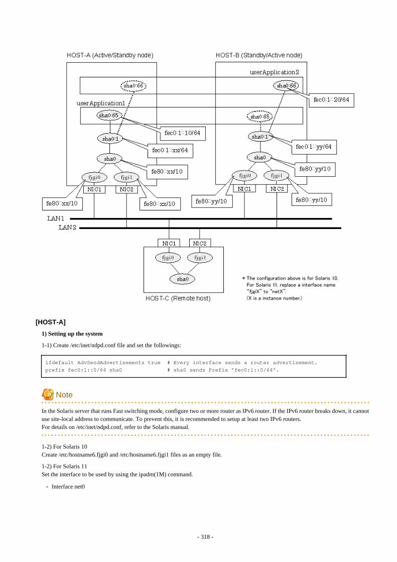
[HOST-A]
1) Setting up the system
1-1) Create /etc/inet/ndpd.conf file and set the followings:
ifdefault AdvSendAdvertisements true # Every interface sends a router advertisement.prefix fec0:1::0/64 sha0 # sha0 sends Prefix "fec0:1::0/64".
Note
In the Solaris server that runs Fast switching mode, configure two or more router as IPv6 router. If the IPv6 router breaks down, it cannotuse site-local address to communicate. To prevent this, it is recommended to setup at least two IPv6 routers.For details on /etc/inet/ndpd.conf, refer to the Solaris manual.
1-2) For Solaris 10Create /etc/hostname6.fjgi0 and /etc/hostname6.fjgi1 files as an empty file.
1-2) For Solaris 11Set the interface to be used by using the ipadm(1M) command.
- Interface net0
- 318 -
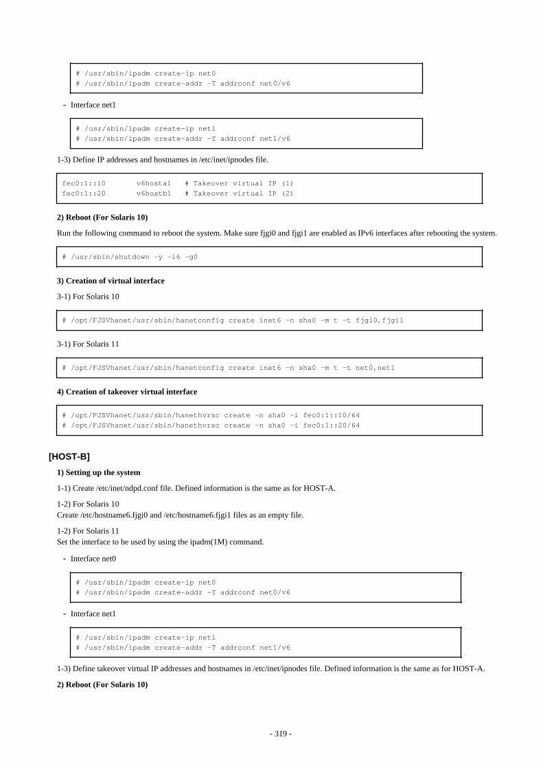
# /usr/sbin/ipadm create-ip net0# /usr/sbin/ipadm create-addr -T addrconf net0/v6
- Interface net1
# /usr/sbin/ipadm create-ip net1# /usr/sbin/ipadm create-addr -T addrconf net1/v6
1-3) Define IP addresses and hostnames in /etc/inet/ipnodes file.
fec0:1::10 v6hosta1 # Takeover virtual IP (1)fec0:1::20 v6hostb1 # Takeover virtual IP (2)
2) Reboot (For Solaris 10)
Run the following command to reboot the system. Make sure fjgi0 and fjgi1 are enabled as IPv6 interfaces after rebooting the system.
# /usr/sbin/shutdown -y -i6 -g0
3) Creation of virtual interface
3-1) For Solaris 10
# /opt/FJSVhanet/usr/sbin/hanetconfig create inet6 -n sha0 -m t -t fjgi0,fjgi1
3-1) For Solaris 11
# /opt/FJSVhanet/usr/sbin/hanetconfig create inet6 -n sha0 -m t -t net0,net1
4) Creation of takeover virtual interface
# /opt/FJSVhanet/usr/sbin/hanethvrsc create -n sha0 -i fec0:1::10/64# /opt/FJSVhanet/usr/sbin/hanethvrsc create -n sha0 -i fec0:1::20/64
[HOST-B]
1) Setting up the system
1-1) Create /etc/inet/ndpd.conf file. Defined information is the same as for HOST-A.
1-2) For Solaris 10Create /etc/hostname6.fjgi0 and /etc/hostname6.fjgi1 files as an empty file.
1-2) For Solaris 11Set the interface to be used by using the ipadm(1M) command.
- Interface net0
# /usr/sbin/ipadm create-ip net0# /usr/sbin/ipadm create-addr -T addrconf net0/v6
- Interface net1
# /usr/sbin/ipadm create-ip net1# /usr/sbin/ipadm create-addr -T addrconf net1/v6
1-3) Define takeover virtual IP addresses and hostnames in /etc/inet/ipnodes file. Defined information is the same as for HOST-A.
2) Reboot (For Solaris 10)
- 319 -

Run the following command to reboot the system. Make sure fjgi0 and fjgi1 are enabled as IPv6 interfaces after rebooting the system.
# /usr/sbin/shutdown -y -i6 -g0
3) Creation of virtual interface
3-1) For Solaris 10
# /opt/FJSVhanet/usr/sbin/hanetconfig create inet6 -n sha0 -m t -t fjgi0,fjgi1
3-1) For Solaris 11
# /opt/FJSVhanet/usr/sbin/hanetconfig create inet6 -n sha0 -m t -t net0,net1
4) Creation of takeover virtual interface
# /opt/FJSVhanet/usr/sbin/hanethvrsc create -n sha0 -i fec0:1::10/64# /opt/FJSVhanet/usr/sbin/hanethvrsc create -n sha0 -i fec0:1::20/64
[Configuration by RMS Wizard]
1) Configuration of userApplication
After completing step 4) of both HOST-A and HOST-B, connect to the administration server using RMS Wizard, then setup the clusterenvironment.To create Gls resources, select the SysNode compliant with HOST-A and HOST-B. Once Gls is created, register the two Gls resourceson the userApplication.When registering on the userApplication, select the SysNode compliant with HOST-A and HOST-B in the order of operation nodefollowed by standby node. Then, register the takeover address "fec0:1::10" and "fec0:1::20".
2) Starting of userApplication
After completing the configuration, start the userApplication to activate the takeover virtual interface on the operation node.
B.2.6 Example of the Cluster system (N:1 Standby)This section describes an example configuration procedure of the network shown in the diagram below.
The values for xx, yy and zz in the IP address of the figure below are assigned automatically by the automatic address configuration.
For configuring the cluster system, refer to the Cluster system manual.In this section, description of private LAN is omitted. The dotted line indicates that the interface is inactive.
Note
When using IPv6 address as a takeover virtual interface, it may take around 30 seconds to recover the communication after switching thenode. In order to hold a communication instantly, start IPv6 routing daemon beforehand on both operating and standby nodes. For detailson this issue, refer to "F.2 Troubleshooting".
- 320 -
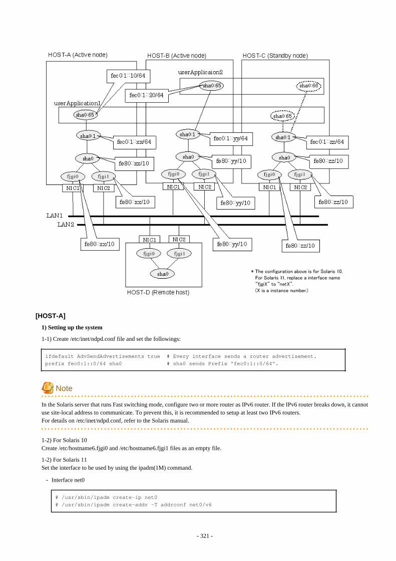
[HOST-A]
1) Setting up the system
1-1) Create /etc/inet/ndpd.conf file and set the followings:
ifdefault AdvSendAdvertisements true # Every interface sends a router advertisement.prefix fec0:1::0/64 sha0 # sha0 sends Prefix "fec0:1::0/64".
Note
In the Solaris server that runs Fast switching mode, configure two or more router as IPv6 router. If the IPv6 router breaks down, it cannotuse site-local address to communicate. To prevent this, it is recommended to setup at least two IPv6 routers.For details on /etc/inet/ndpd.conf, refer to the Solaris manual.
1-2) For Solaris 10Create /etc/hostname6.fjgi0 and /etc/hostname6.fjgi1 files as an empty file.
1-2) For Solaris 11Set the interface to be used by using the ipadm(1M) command.
- Interface net0
# /usr/sbin/ipadm create-ip net0# /usr/sbin/ipadm create-addr -T addrconf net0/v6
- 321 -
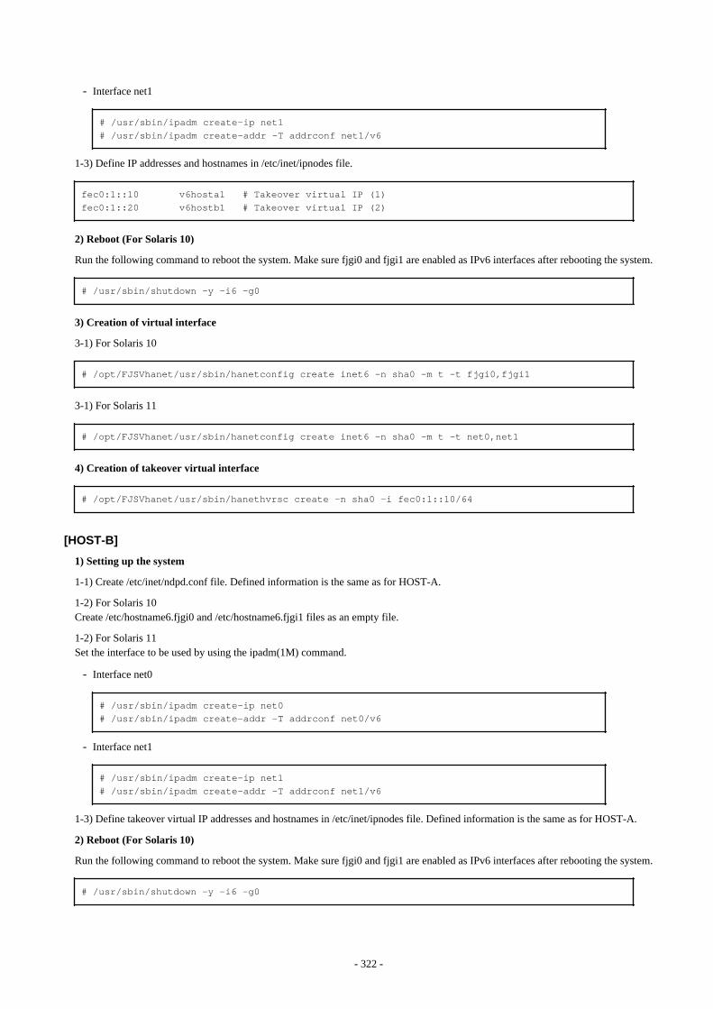
- Interface net1
# /usr/sbin/ipadm create-ip net1# /usr/sbin/ipadm create-addr -T addrconf net1/v6
1-3) Define IP addresses and hostnames in /etc/inet/ipnodes file.
fec0:1::10 v6hosta1 # Takeover virtual IP (1)fec0:1::20 v6hostb1 # Takeover virtual IP (2)
2) Reboot (For Solaris 10)
Run the following command to reboot the system. Make sure fjgi0 and fjgi1 are enabled as IPv6 interfaces after rebooting the system.
# /usr/sbin/shutdown -y -i6 -g0
3) Creation of virtual interface
3-1) For Solaris 10
# /opt/FJSVhanet/usr/sbin/hanetconfig create inet6 -n sha0 -m t -t fjgi0,fjgi1
3-1) For Solaris 11
# /opt/FJSVhanet/usr/sbin/hanetconfig create inet6 -n sha0 -m t -t net0,net1
4) Creation of takeover virtual interface
# /opt/FJSVhanet/usr/sbin/hanethvrsc create -n sha0 -i fec0:1::10/64
[HOST-B]
1) Setting up the system
1-1) Create /etc/inet/ndpd.conf file. Defined information is the same as for HOST-A.
1-2) For Solaris 10Create /etc/hostname6.fjgi0 and /etc/hostname6.fjgi1 files as an empty file.
1-2) For Solaris 11Set the interface to be used by using the ipadm(1M) command.
- Interface net0
# /usr/sbin/ipadm create-ip net0# /usr/sbin/ipadm create-addr -T addrconf net0/v6
- Interface net1
# /usr/sbin/ipadm create-ip net1# /usr/sbin/ipadm create-addr -T addrconf net1/v6
1-3) Define takeover virtual IP addresses and hostnames in /etc/inet/ipnodes file. Defined information is the same as for HOST-A.
2) Reboot (For Solaris 10)
Run the following command to reboot the system. Make sure fjgi0 and fjgi1 are enabled as IPv6 interfaces after rebooting the system.
# /usr/sbin/shutdown -y -i6 -g0
- 322 -
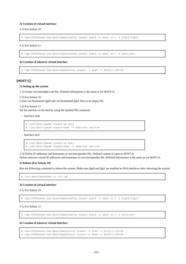
3) Creation of virtual interface
3-1) For Solaris 10
# /opt/FJSVhanet/usr/sbin/hanetconfig create inet6 -n sha0 -m t -t fjgi0,fjgi1
3-1) For Solaris 11
# /opt/FJSVhanet/usr/sbin/hanetconfig create inet6 -n sha0 -m t -t net0,net1
4) Creation of takeover virtual interface
# /opt/FJSVhanet/usr/sbin/hanethvrsc create -n sha0 -i fec0:1::20/64
[HOST-C]
1) Setting up the system
1-1) Create /etc/inet/ndpd.conf file. Defined information is the same as for HOST-A.
1-2) For Solaris 10Create /etc/hostname6.fjgi0 and /etc/hostname6.fjgi1 files as an empty file.
1-2) For Solaris 11Set the interface to be used by using the ipadm(1M) command.
- Interface net0
# /usr/sbin/ipadm create-ip net0# /usr/sbin/ipadm create-addr -T addrconf net0/v6
- Interface net1
# /usr/sbin/ipadm create-ip net1# /usr/sbin/ipadm create-addr -T addrconf net1/v6
1-3) Define IP addresses and hostnames in /etc/inet/ipnodes file. Defined content is same as HOST-A.Define takeover virtual IP addresses and hostnames in /etc/inet/ipnodes file. Defined information is the same as for HOST-A.
2) Reboot (For Solaris 10)
Run the following command to reboot the system. Make sure fjgi0 and fjgi1 are enabled as IPv6 interfaces after rebooting the system.
# /usr/sbin/shutdown -y -i6 -g0
3) Creation of virtual interface
3-1) For Solaris 10
# /opt/FJSVhanet/usr/sbin/hanetconfig create inet6 -n sha0 -m t -t fjgi0,fjgi1
3-1) For Solaris 11
# /opt/FJSVhanet/usr/sbin/hanetconfig create inet6 -n sha0 -m t -t net0,net1
4) Creation of takeover virtual interface
# /opt/FJSVhanet/usr/sbin/hanethvrsc create -n sha0 -i fec0:1::10/64# /opt/FJSVhanet/usr/sbin/hanethvrsc create -n sha0 -i fec0:1::20/64
- 323 -
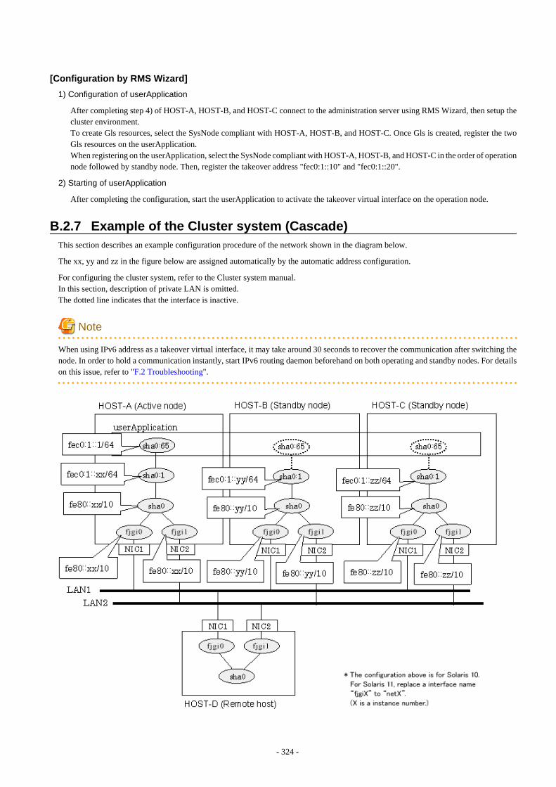
[Configuration by RMS Wizard]
1) Configuration of userApplication
After completing step 4) of HOST-A, HOST-B, and HOST-C connect to the administration server using RMS Wizard, then setup thecluster environment.To create Gls resources, select the SysNode compliant with HOST-A, HOST-B, and HOST-C. Once Gls is created, register the twoGls resources on the userApplication.When registering on the userApplication, select the SysNode compliant with HOST-A, HOST-B, and HOST-C in the order of operationnode followed by standby node. Then, register the takeover address "fec0:1::10" and "fec0:1::20".
2) Starting of userApplication
After completing the configuration, start the userApplication to activate the takeover virtual interface on the operation node.
B.2.7 Example of the Cluster system (Cascade)This section describes an example configuration procedure of the network shown in the diagram below.
The xx, yy and zz in the figure below are assigned automatically by the automatic address configuration.
For configuring the cluster system, refer to the Cluster system manual.In this section, description of private LAN is omitted. The dotted line indicates that the interface is inactive.
Note
When using IPv6 address as a takeover virtual interface, it may take around 30 seconds to recover the communication after switching thenode. In order to hold a communication instantly, start IPv6 routing daemon beforehand on both operating and standby nodes. For detailson this issue, refer to "F.2 Troubleshooting".
- 324 -
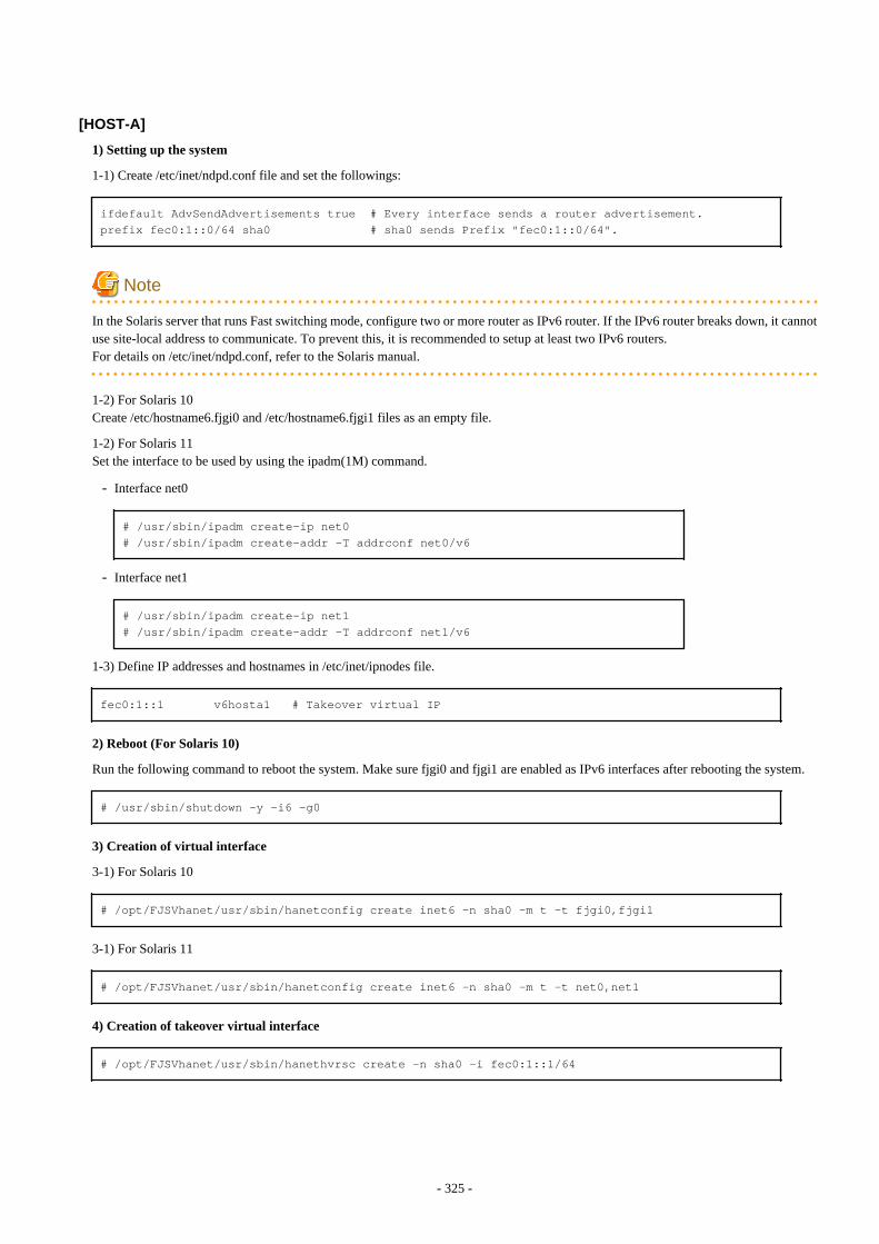
[HOST-A]
1) Setting up the system
1-1) Create /etc/inet/ndpd.conf file and set the followings:
ifdefault AdvSendAdvertisements true # Every interface sends a router advertisement.prefix fec0:1::0/64 sha0 # sha0 sends Prefix "fec0:1::0/64".
Note
In the Solaris server that runs Fast switching mode, configure two or more router as IPv6 router. If the IPv6 router breaks down, it cannotuse site-local address to communicate. To prevent this, it is recommended to setup at least two IPv6 routers.For details on /etc/inet/ndpd.conf, refer to the Solaris manual.
1-2) For Solaris 10Create /etc/hostname6.fjgi0 and /etc/hostname6.fjgi1 files as an empty file.
1-2) For Solaris 11Set the interface to be used by using the ipadm(1M) command.
- Interface net0
# /usr/sbin/ipadm create-ip net0# /usr/sbin/ipadm create-addr -T addrconf net0/v6
- Interface net1
# /usr/sbin/ipadm create-ip net1# /usr/sbin/ipadm create-addr -T addrconf net1/v6
1-3) Define IP addresses and hostnames in /etc/inet/ipnodes file.
fec0:1::1 v6hosta1 # Takeover virtual IP
2) Reboot (For Solaris 10)
Run the following command to reboot the system. Make sure fjgi0 and fjgi1 are enabled as IPv6 interfaces after rebooting the system.
# /usr/sbin/shutdown -y -i6 -g0
3) Creation of virtual interface
3-1) For Solaris 10
# /opt/FJSVhanet/usr/sbin/hanetconfig create inet6 -n sha0 -m t -t fjgi0,fjgi1
3-1) For Solaris 11
# /opt/FJSVhanet/usr/sbin/hanetconfig create inet6 -n sha0 -m t -t net0,net1
4) Creation of takeover virtual interface
# /opt/FJSVhanet/usr/sbin/hanethvrsc create -n sha0 -i fec0:1::1/64
- 325 -

[HOST-B]
1) Setting up the system
1-1) Create /etc/inet/ndpd.conf file. Defined information is the same as for HOST-A.
1-2) For Solaris 10Create /etc/hostname6.fjgi0 and /etc/hostname6.fjgi1 files as an empty file.
1-2) For Solaris 11Set the interface to be used by using the ipadm(1M) command.
- Interface net0
# /usr/sbin/ipadm create-ip net0# /usr/sbin/ipadm create-addr -T addrconf net0/v6
- Interface net1
# /usr/sbin/ipadm create-ip net1# /usr/sbin/ipadm create-addr -T addrconf net1/v6
1-3) Define takeover virtual IP addresses and hostnames in /etc/inet/ipnodes file. Defined information is the same as for HOST-A.
2) Reboot (For Solaris 10)
Run the following command to reboot the system. Make sure fjgi0 and fjgi1 are enabled as IPv6 interfaces after rebooting the system.
# /usr/sbin/shutdown -y -i6 -g0
3) Creation of virtual interface
3-1) For Solaris 10
# /opt/FJSVhanet/usr/sbin/hanetconfig create inet6 -n sha0 -m t -t fjgi0,fjgi1
3-1) For Solaris 11
# /opt/FJSVhanet/usr/sbin/hanetconfig create inet6 -n sha0 -m t -t net0,net1
4) Creation of takeover virtual interface
# /opt/FJSVhanet/usr/sbin/hanethvrsc create -n sha0 -i fec0:1::1/64
[HOST-C]
1) Setting up the system
1-1) Create /etc/inet/ndpd.conf file. Defined information is the same as for HOST-A.
1-2) For Solaris 10Create /etc/hostname6.fjgi0 and /etc/hostname6.fjgi1 files as an empty file.
1-2) For Solaris 11Set the interface to be used by using the ipadm(1M) command.
- Interface net0
# /usr/sbin/ipadm create-ip net0# /usr/sbin/ipadm create-addr -T addrconf net0/v6
- Interface net1
- 326 -
# /usr/sbin/ipadm create-ip net1# /usr/sbin/ipadm create-addr -T addrconf net1/v6
1-3) Define takeover virtual IP addresses and hostnames in /etc/inet/ipnodes file. Defined information is the same as for HOST-A.
2) Reboot (For Solaris 10)
Run the following command to reboot the system. Make sure fjgi0 and fjgi1 are enabled as IPv6 interfaces after rebooting the system.
# /usr/sbin/shutdown -y -i6 -g0
3) Creation of virtual interface
3-1) For Solaris 10
# /opt/FJSVhanet/usr/sbin/hanetconfig create inet6 -n sha0 -m t -t fjgi0,fjgi1
3-1) For Solaris 11
# /opt/FJSVhanet/usr/sbin/hanetconfig create inet6 -n sha0 -m t -t net0,net1
4) Creation of takeover virtual interface
# /opt/FJSVhanet/usr/sbin/hanethvrsc create -n sha0 -i fec0:1::1/64
[Configuration by RMS Wizard]
1) Configuration of userApplication
After completing step 4) of both HOST-B and HOST-C, connect to the administration server using RMS Wizar, then setup the clusterenvironment.To create Gls resources, select the SysNode compliant with HOST-A, HOST-B, and HOST-C. Once Gls is created, register the twoGls resources on the userApplication.When registering on the userApplication, select the SysNode compliant with HOST-A, HOST-B, and HOST-C in the order of operationnode followed by standby node. Then, register the takeover address "fec0:1::1".
2) Starting of userApplication
After completing the configuration, start the userApplication to activate the takeover virtual interface on the operation node.
B.3 Example of configuring Fast Switching mode (IPv4/IPv6)
B.3.1 Example of the Single systemThis section describes an example configuration procedure of the network shown in the diagram below.
The xx, yy in the figure below are assigned automatically by the automatic address configuration.
- 327 -
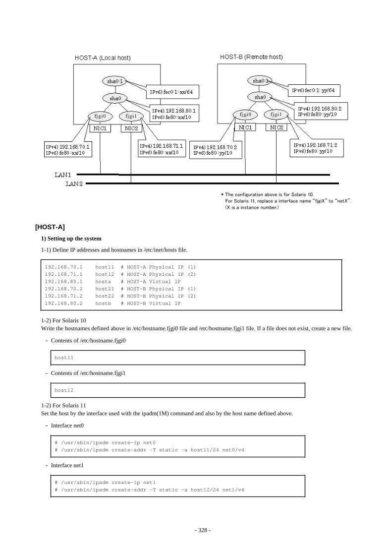
[HOST-A]
1) Setting up the system
1-1) Define IP addresses and hostnames in /etc/inet/hosts file.
192.168.70.1 host11 # HOST-A Physical IP (1)192.168.71.1 host12 # HOST-A Physical IP (2)192.168.80.1 hosta # HOST-A Virtual IP192.168.70.2 host21 # HOST-B Physical IP (1)192.168.71.2 host22 # HOST-B Physical IP (2)192.168.80.2 hostb # HOST-B Virtual IP
1-2) For Solaris 10Write the hostnames defined above in /etc/hostname.fjgi0 file and /etc/hostname.fjgi1 file. If a file does not exist, create a new file.
- Contents of /etc/hostname.fjgi0
host11
- Contents of /etc/hostname.fjgi1
host12
1-2) For Solaris 11Set the host by the interface used with the ipadm(1M) command and also by the host name defined above.
- Interface net0
# /usr/sbin/ipadm create-ip net0# /usr/sbin/ipadm create-addr -T static -a host11/24 net0/v4
- Interface net1
# /usr/sbin/ipadm create-ip net1# /usr/sbin/ipadm create-addr -T static -a host12/24 net1/v4
- 328 -
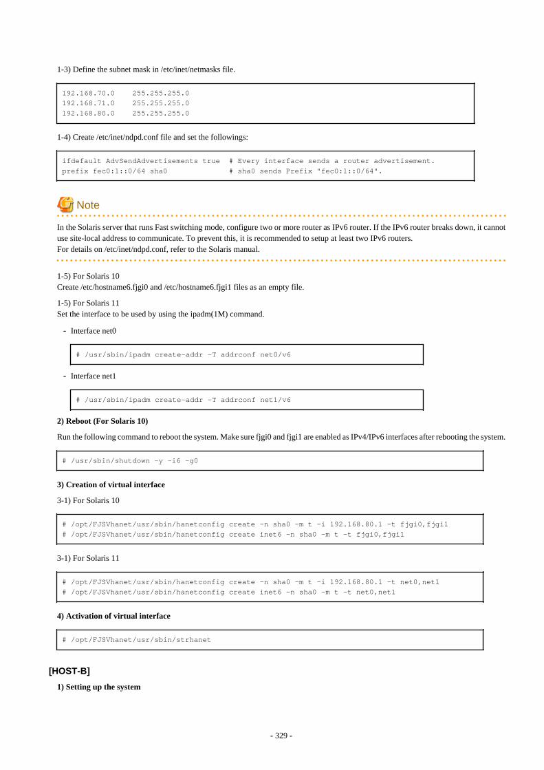
1-3) Define the subnet mask in /etc/inet/netmasks file.
192.168.70.0 255.255.255.0192.168.71.0 255.255.255.0192.168.80.0 255.255.255.0
1-4) Create /etc/inet/ndpd.conf file and set the followings:
ifdefault AdvSendAdvertisements true # Every interface sends a router advertisement.prefix fec0:1::0/64 sha0 # sha0 sends Prefix "fec0:1::0/64".
Note
In the Solaris server that runs Fast switching mode, configure two or more router as IPv6 router. If the IPv6 router breaks down, it cannotuse site-local address to communicate. To prevent this, it is recommended to setup at least two IPv6 routers.For details on /etc/inet/ndpd.conf, refer to the Solaris manual.
1-5) For Solaris 10Create /etc/hostname6.fjgi0 and /etc/hostname6.fjgi1 files as an empty file.
1-5) For Solaris 11Set the interface to be used by using the ipadm(1M) command.
- Interface net0
# /usr/sbin/ipadm create-addr -T addrconf net0/v6
- Interface net1
# /usr/sbin/ipadm create-addr -T addrconf net1/v6
2) Reboot (For Solaris 10)
Run the following command to reboot the system. Make sure fjgi0 and fjgi1 are enabled as IPv4/IPv6 interfaces after rebooting the system.
# /usr/sbin/shutdown -y -i6 -g0
3) Creation of virtual interface
3-1) For Solaris 10
# /opt/FJSVhanet/usr/sbin/hanetconfig create -n sha0 -m t -i 192.168.80.1 -t fjgi0,fjgi1# /opt/FJSVhanet/usr/sbin/hanetconfig create inet6 -n sha0 -m t -t fjgi0,fjgi1
3-1) For Solaris 11
# /opt/FJSVhanet/usr/sbin/hanetconfig create -n sha0 -m t -i 192.168.80.1 -t net0,net1# /opt/FJSVhanet/usr/sbin/hanetconfig create inet6 -n sha0 -m t -t net0,net1
4) Activation of virtual interface
# /opt/FJSVhanet/usr/sbin/strhanet
[HOST-B]
1) Setting up the system
- 329 -
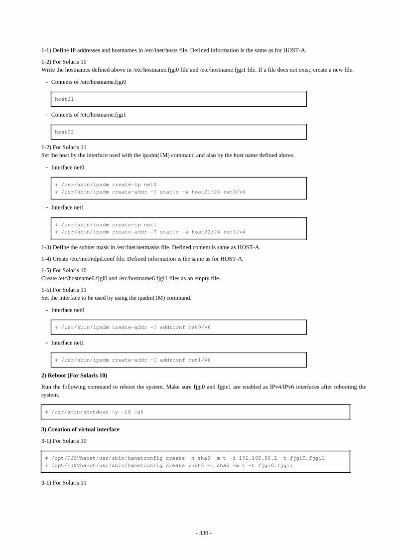
1-1) Define IP addresses and hostnames in /etc/inet/hosts file. Defined information is the same as for HOST-A.
1-2) For Solaris 10Write the hostnames defined above in /etc/hostname.fjgi0 file and /etc/hostname.fjgi1 file. If a file does not exist, create a new file.
- Contents of /etc/hostname.fjgi0
host21
- Contents of /etc/hostname.fjgi1
host22
1-2) For Solaris 11Set the host by the interface used with the ipadm(1M) command and also by the host name defined above.
- Interface net0
# /usr/sbin/ipadm create-ip net0# /usr/sbin/ipadm create-addr -T static -a host21/24 net0/v4
- Interface net1
# /usr/sbin/ipadm create-ip net1# /usr/sbin/ipadm create-addr -T static -a host22/24 net1/v4
1-3) Define the subnet mask in /etc/inet/netmasks file. Defined content is same as HOST-A.
1-4) Create /etc/inet/ndpd.conf file. Defined information is the same as for HOST-A.
1-5) For Solaris 10Create /etc/hostname6.fjgi0 and /etc/hostname6.fjgi1 files as an empty file.
1-5) For Solaris 11Set the interface to be used by using the ipadm(1M) command.
- Interface net0
# /usr/sbin/ipadm create-addr -T addrconf net0/v6
- Interface net1
# /usr/sbin/ipadm create-addr -T addrconf net1/v6
2) Reboot (For Solaris 10)
Run the following command to reboot the system. Make sure fjgi0 and fjgie1 are enabled as IPv4/IPv6 interfaces after rebooting thesystem.
# /usr/sbin/shutdown -y -i6 -g0
3) Creation of virtual interface
3-1) For Solaris 10
# /opt/FJSVhanet/usr/sbin/hanetconfig create -n sha0 -m t -i 192.168.80.2 -t fjgi0,fjgi1# /opt/FJSVhanet/usr/sbin/hanetconfig create inet6 -n sha0 -m t -t fjgi0,fjgi1
3-1) For Solaris 11
- 330 -
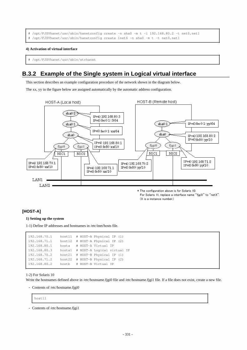
# /opt/FJSVhanet/usr/sbin/hanetconfig create -n sha0 -m t -i 192.168.80.2 -t net0,net1# /opt/FJSVhanet/usr/sbin/hanetconfig create inet6 -n sha0 -m t -t net0,net1
4) Activation of virtual interface
# /opt/FJSVhanet/usr/sbin/strhanet
B.3.2 Example of the Single system in Logical virtual interfaceThis section describes an example configuration procedure of the network shown in the diagram below.
The xx, yy in the figure below are assigned automatically by the automatic address configuration.
[HOST-A]
1) Setting up the system
1-1) Define IP addresses and hostnames in /etc/inet/hosts file.
192.168.70.1 host11 # HOST-A Physical IP (1)192.168.71.1 host12 # HOST-A Physical IP (2)192.168.80.1 hosta # HOST-A Virtual IP192.168.80.3 hosta1 # HOST-A Logical virtual IP 192.168.70.2 host21 # HOST-B Physical IP (1)192.168.71.2 host22 # HOST-B Physical IP (2)192.168.80.2 hostb # HOST-B Virtual IP
1-2) For Solaris 10Write the hostnames defined above in /etc/hostname.fjgi0 file and /etc/hostname.fjgi1 file. If a file does not exist, create a new file.
- Contents of /etc/hostname.fjgi0
host11
- Contents of /etc/hostname.fjgi1
- 331 -
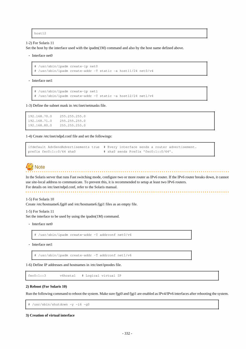
host12
1-2) For Solaris 11Set the host by the interface used with the ipadm(1M) command and also by the host name defined above.
- Interface net0
# /usr/sbin/ipadm create-ip net0# /usr/sbin/ipadm create-addr -T static -a host11/24 net0/v4
- Interface net1
# /usr/sbin/ipadm create-ip net1# /usr/sbin/ipadm create-addr -T static -a host12/24 net1/v4
1-3) Define the subnet mask in /etc/inet/netmasks file.
192.168.70.0 255.255.255.0192.168.71.0 255.255.255.0192.168.80.0 255.255.255.0
1-4) Create /etc/inet/ndpd.conf file and set the followings:
ifdefault AdvSendAdvertisements true # Every interface sends a router advertisement.prefix fec0:1::0/64 sha0 # sha0 sends Prefix "fec0:1::0/64".
Note
In the Solaris server that runs Fast switching mode, configure two or more router as IPv6 router. If the IPv6 router breaks down, it cannotuse site-local address to communicate. To prevent this, it is recommended to setup at least two IPv6 routers.For details on /etc/inet/ndpd.conf, refer to the Solaris manual.
1-5) For Solaris 10Create /etc/hostname6.fjgi0 and /etc/hostname6.fjgi1 files as an empty file.
1-5) For Solaris 11Set the interface to be used by using the ipadm(1M) command.
- Interface net0
# /usr/sbin/ipadm create-addr -T addrconf net0/v6
- Interface net1
# /usr/sbin/ipadm create-addr -T addrconf net1/v6
1-6) Define IP addresses and hostnames in /etc/inet/ipnodes file.
fec0:1::3 v6hosta1 # Logical virtual IP
2) Reboot (For Solaris 10)
Run the following command to reboot the system. Make sure fjgi0 and fjgi1 are enabled as IPv4/IPv6 interfaces after rebooting the system.
# /usr/sbin/shutdown -y -i6 -g0
3) Creation of virtual interface
- 332 -

3-1) For Solaris 10
# /opt/FJSVhanet/usr/sbin/hanetconfig create -n sha0 -m t -i 192.168.80.1 -t fjgi0,fjgi1# /opt/FJSVhanet/usr/sbin/hanetconfig create inet6 -n sha0 -m t -t fjgi0,fjgi1
3-1) For Solaris 11
# /opt/FJSVhanet/usr/sbin/hanetconfig create -n sha0 -m t -i 192.168.80.1 -t net0,net1# /opt/FJSVhanet/usr/sbin/hanetconfig create inet6 -n sha0 -m t -t net0,net1
4) Creation of logical virtual interface
# /opt/FJSVhanet/usr/sbin/hanetconfig create -n sha0:2 -i 192.168.80.3# /opt/FJSVhanet/usr/sbin/hanetconfig create inet6 -n sha0:2 -i fec0:1::3/64
5) Activation of virtual interface
# /opt/FJSVhanet/usr/sbin/strhanet
[HOST-B]
1) Setting up the system
1-1) Define IP addresses and hostnames in /etc/inet/hosts file. Defined information is the same as for HOST-A.
1-2) For Solaris 10Write the hostnames defined above in /etc/hostname.fjgi0 file and /etc/hostname.fjgi1 file. If a file does not exist, create a new file.
- Contents of /etc/hostname.fjgi0
host21
- Contents of /etc/hostname.fjgi1
host22
1-2) For Solaris 11Set the host by the interface used with the ipadm(1M) command and also by the host name defined above.
- Interface net0
# /usr/sbin/ipadm create-ip net0# /usr/sbin/ipadm create-addr -T static -a host21/24 net0/v4
- Interface net1
# /usr/sbin/ipadm create-ip net1# /usr/sbin/ipadm create-addr -T static -a host22/24 net1/v4
1-3) Define the subnet mask in /etc/inet/netmasks file. Defined content is same as HOST-A.
1-4) Create /etc/inet/ndpd.conf file. Defined information is the same as for HOST-A.
1-5) For Solaris 10Create /etc/hostname6.fjgi0 and /etc/hostname6.fjgi1 files as an empty file.
1-5) For Solaris 11Set the interface to be used by using the ipadm(1M) command.
- Interface net0
- 333 -
# /usr/sbin/ipadm create-addr -T addrconf net0/v6
- Interface net1
# /usr/sbin/ipadm create-addr -T addrconf net1/v6
1-6) Define IP addresses and hostnames in /etc/inet/ipnodes file. Defined content is same as HOST-A.
2) Reboot (For Solaris 10)
Run the following command to reboot the system. Make sure fjgi0 and fjgi1 are enabled as IPv4/IPv6 interfaces after rebooting the system.
# /usr/sbin/shutdown -y -i6 -g0
3) Creation of virtual interface
3-1) For Solaris 10
# /opt/FJSVhanet/usr/sbin/hanetconfig create -n sha0 -m t -i 192.168.80.2 -t fjgi0,fjgi1# /opt/FJSVhanet/usr/sbin/hanetconfig create inet6 -n sha0 -m t -t fjgi0,fjgi1
3-1) For Solaris 11
# /opt/FJSVhanet/usr/sbin/hanetconfig create -n sha0 -m t -i 192.168.80.2 -t net0,net1# /opt/FJSVhanet/usr/sbin/hanetconfig create inet6 -n sha0 -m t -t net0,net1
4) Activation of virtual interface
# /opt/FJSVhanet/usr/sbin/strhanet
B.3.3 Configuring virtual interfaces with tagged VLANThis section describes an example configuration procedure of the network shown in the diagram below.
The xx, yy and zz in the figure below are assigned automatically by the automatic address configuration.
- 334 -
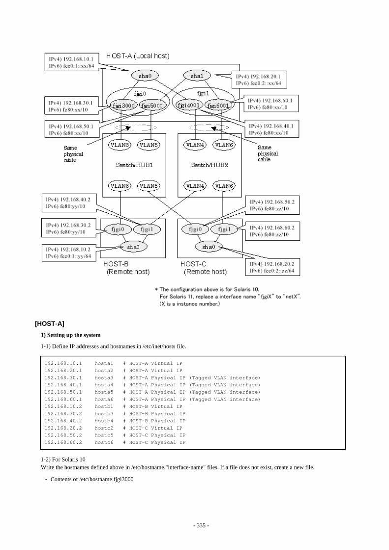
[HOST-A]
1) Setting up the system
1-1) Define IP addresses and hostnames in /etc/inet/hosts file.
192.168.10.1 hosta1 # HOST-A Virtual IP192.168.20.1 hosta2 # HOST-A Virtual IP192.168.30.1 hosta3 # HOST-A Physical IP (Tagged VLAN interface)192.168.40.1 hosta4 # HOST-A Physical IP (Tagged VLAN interface)192.168.50.1 hosta5 # HOST-A Physical IP (Tagged VLAN interface)192.168.60.1 hosta6 # HOST-A Physical IP (Tagged VLAN interface)192.168.10.2 hostb1 # HOST-B Virtual IP192.168.30.2 hostb3 # HOST-B Physical IP192.168.40.2 hostb4 # HOST-B Physical IP192.168.20.2 hostc2 # HOST-C Virtual IP192.168.50.2 hostc5 # HOST-C Physical IP192.168.60.2 hostc6 # HOST-C Physical IP
1-2) For Solaris 10Write the hostnames defined above in /etc/hostname."interface-name" files. If a file does not exist, create a new file.
- Contents of /etc/hostname.fjgi3000
- 335 -
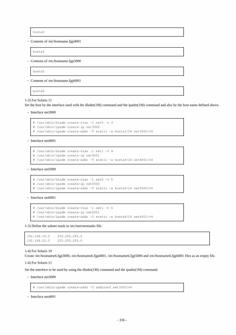
hosta3
- Contents of /etc/hostname.fjgi4001
hosta4
- Contents of /etc/hostname.fjgi5000
hosta5
- Contents of /etc/hostname.fjgi6001
hosta6
1-2) For Solaris 11Set the host by the interface used with the dladm(1M) command and the ipadm(1M) command and also by the host name defined above.
- Interface net3000
# /usr/sbin/dladm create-vlan -l net0 -v 3# /usr/sbin/ipadm create-ip net3000# /usr/sbin/ipadm create-addr -T static -a hosta3/24 net3000/v4
- Interface net4001
# /usr/sbin/dladm create-vlan -l net1 -v 4# /usr/sbin/ipadm create-ip net4001# /usr/sbin/ipadm create-addr -T static -a hosta4/24 net4001/v4
- Interface net5000
# /usr/sbin/dladm create-vlan -l net0 -v 5# /usr/sbin/ipadm create-ip net5000# /usr/sbin/ipadm create-addr -T static -a hosta5/24 net5000/v4
- Interface net6001
# /usr/sbin/dladm create-vlan -l net1 -v 6# /usr/sbin/ipadm create-ip net6001# /usr/sbin/ipadm create-addr -T static -a hosta6/24 net6001/v4
1-3) Define the subnet mask in /etc/inet/netmasks file.
192.168.10.0 255.255.255.0192.168.20.0 255.255.255.0
1-4) For Solaris 10Create /etc/hostname6.fjgi3000, /etc/hostname6.fjgi4001, /etc/hostname6.fjgi5000 and /etc/hostname6.fjgi6001 files as an empty file.
1-4) For Solaris 11
Set the interface to be used by using the dladm(1M) command and the ipadm(1M) command.
- Interface net3000
# /usr/sbin/ipadm create-addr -T addrconf net3000/v6
- Interface net4001
- 336 -
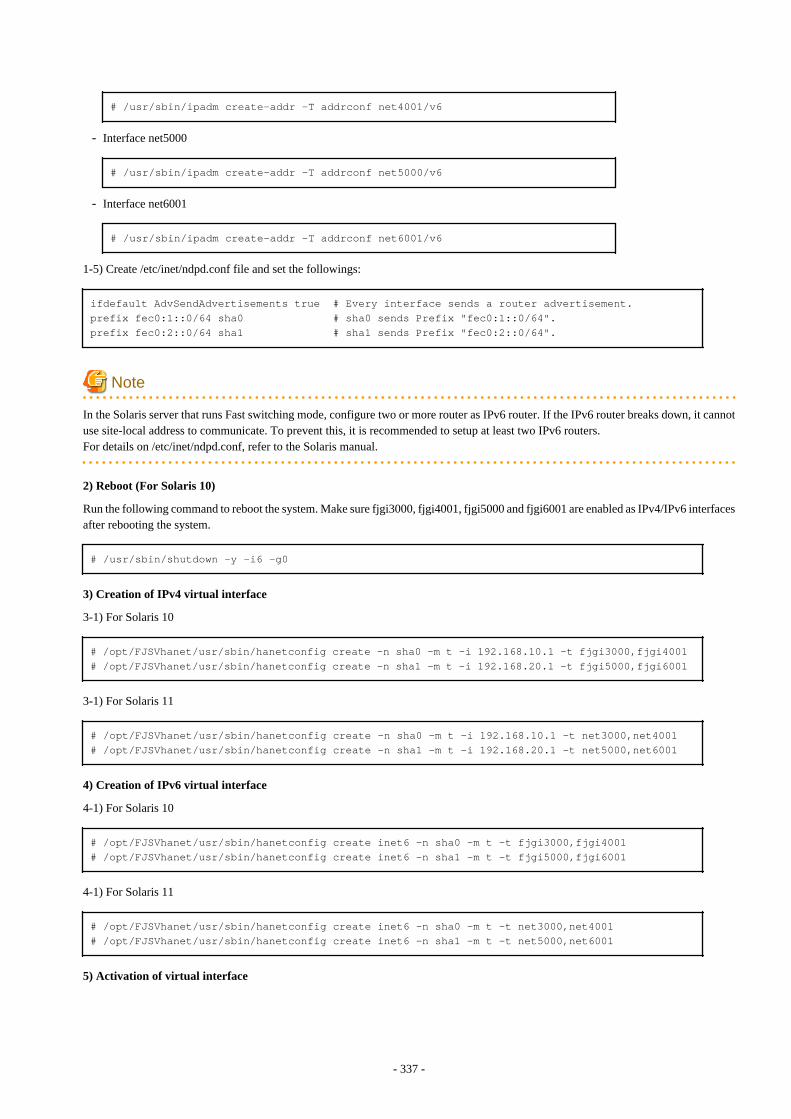
# /usr/sbin/ipadm create-addr -T addrconf net4001/v6
- Interface net5000
# /usr/sbin/ipadm create-addr -T addrconf net5000/v6
- Interface net6001
# /usr/sbin/ipadm create-addr -T addrconf net6001/v6
1-5) Create /etc/inet/ndpd.conf file and set the followings:
ifdefault AdvSendAdvertisements true # Every interface sends a router advertisement.prefix fec0:1::0/64 sha0 # sha0 sends Prefix "fec0:1::0/64".prefix fec0:2::0/64 sha1 # sha1 sends Prefix "fec0:2::0/64".
Note
In the Solaris server that runs Fast switching mode, configure two or more router as IPv6 router. If the IPv6 router breaks down, it cannotuse site-local address to communicate. To prevent this, it is recommended to setup at least two IPv6 routers.For details on /etc/inet/ndpd.conf, refer to the Solaris manual.
2) Reboot (For Solaris 10)
Run the following command to reboot the system. Make sure fjgi3000, fjgi4001, fjgi5000 and fjgi6001 are enabled as IPv4/IPv6 interfacesafter rebooting the system.
# /usr/sbin/shutdown -y -i6 -g0
3) Creation of IPv4 virtual interface
3-1) For Solaris 10
# /opt/FJSVhanet/usr/sbin/hanetconfig create -n sha0 -m t -i 192.168.10.1 -t fjgi3000,fjgi4001# /opt/FJSVhanet/usr/sbin/hanetconfig create -n sha1 -m t -i 192.168.20.1 -t fjgi5000,fjgi6001
3-1) For Solaris 11
# /opt/FJSVhanet/usr/sbin/hanetconfig create -n sha0 -m t -i 192.168.10.1 -t net3000,net4001# /opt/FJSVhanet/usr/sbin/hanetconfig create -n sha1 -m t -i 192.168.20.1 -t net5000,net6001
4) Creation of IPv6 virtual interface
4-1) For Solaris 10
# /opt/FJSVhanet/usr/sbin/hanetconfig create inet6 -n sha0 -m t -t fjgi3000,fjgi4001# /opt/FJSVhanet/usr/sbin/hanetconfig create inet6 -n sha1 -m t -t fjgi5000,fjgi6001
4-1) For Solaris 11
# /opt/FJSVhanet/usr/sbin/hanetconfig create inet6 -n sha0 -m t -t net3000,net4001# /opt/FJSVhanet/usr/sbin/hanetconfig create inet6 -n sha1 -m t -t net5000,net6001
5) Activation of virtual interface
- 337 -
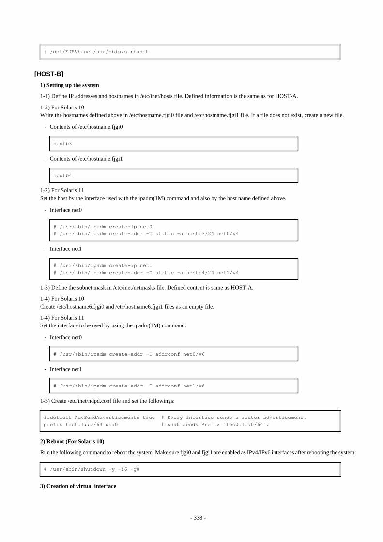
# /opt/FJSVhanet/usr/sbin/strhanet
[HOST-B]
1) Setting up the system
1-1) Define IP addresses and hostnames in /etc/inet/hosts file. Defined information is the same as for HOST-A.
1-2) For Solaris 10Write the hostnames defined above in /etc/hostname.fjgi0 file and /etc/hostname.fjgi1 file. If a file does not exist, create a new file.
- Contents of /etc/hostname.fjgi0
hostb3
- Contents of /etc/hostname.fjgi1
hostb4
1-2) For Solaris 11Set the host by the interface used with the ipadm(1M) command and also by the host name defined above.
- Interface net0
# /usr/sbin/ipadm create-ip net0# /usr/sbin/ipadm create-addr -T static -a hostb3/24 net0/v4
- Interface net1
# /usr/sbin/ipadm create-ip net1# /usr/sbin/ipadm create-addr -T static -a hostb4/24 net1/v4
1-3) Define the subnet mask in /etc/inet/netmasks file. Defined content is same as HOST-A.
1-4) For Solaris 10Create /etc/hostname6.fjgi0 and /etc/hostname6.fjgi1 files as an empty file.
1-4) For Solaris 11Set the interface to be used by using the ipadm(1M) command.
- Interface net0
# /usr/sbin/ipadm create-addr -T addrconf net0/v6
- Interface net1
# /usr/sbin/ipadm create-addr -T addrconf net1/v6
1-5) Create /etc/inet/ndpd.conf file and set the followings:
ifdefault AdvSendAdvertisements true # Every interface sends a router advertisement.prefix fec0:1::0/64 sha0 # sha0 sends Prefix "fec0:1::0/64".
2) Reboot (For Solaris 10)
Run the following command to reboot the system. Make sure fjgi0 and fjgi1 are enabled as IPv4/IPv6 interfaces after rebooting the system.
# /usr/sbin/shutdown -y -i6 -g0
3) Creation of virtual interface
- 338 -

3-1) For Solaris 10
# /opt/FJSVhanet/usr/sbin/hanetconfig create -n sha0 -m t -i 192.168.10.2 -t fjgi0,fjgi1# /opt/FJSVhanet/usr/sbin/hanetconfig create inet6 -n sha0 -m t -t fjgi0,fjgi1
3-1) For Solaris 11
# /opt/FJSVhanet/usr/sbin/hanetconfig create -n sha0 -m t -i 192.168.10.2 -t net0,net1# /opt/FJSVhanet/usr/sbin/hanetconfig create inet6 -n sha0 -m t -t net0,net1
4) Activation of virtual interface
# /opt/FJSVhanet/usr/sbin/strhanet
[HOST-C]
1) Setting up the system
1-1) Define IP addresses and hostnames in /etc/inet/hosts file. Defined information is the same as for HOST-A.
1-2) For Solaris 10Write the hostnames defined above in /etc/hostname.fjgi0 file and /etc/hostname.fjgi1 file. If a file does not exist, create a new file.
- Contents of /etc/hostname.fjgi0
hostc5
- Contents of /etc/hostname.fjgi1
hostc6
1-2) For Solaris 11Set the host by the interface used with the ipadm(1M) command and also by the host name defined above.
- Interface net0
# /usr/sbin/ipadm create-ip net0# /usr/sbin/ipadm create-addr -T static -a hostc5/24 net0/v4
- Interface net1
# /usr/sbin/ipadm create-ip net1# /usr/sbin/ipadm create-addr -T static -a hostc6/24 net1/v4
1-3) Define the subnet mask in /etc/inet/netmasks file. Defined content is same as HOST-A.
1-4) For Solaris 10Create /etc/hostname6.hfjgi0 and /etc/hostname6.fjgi1 files as an empty file.
1-4) For Solaris 11Set the interface to be used by using the ipadm(1M) command.
- Interface net0
# /usr/sbin/ipadm create-addr -T addrconf net0/v6
- Interface net1
# /usr/sbin/ipadm create-addr -T addrconf net1/v6
- 339 -
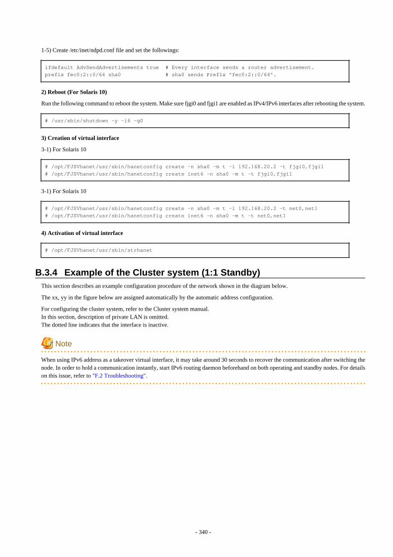
1-5) Create /etc/inet/ndpd.conf file and set the followings:
ifdefault AdvSendAdvertisements true # Every interface sends a router advertisement.prefix fec0:2::0/64 sha0 # sha0 sends Prefix "fec0:2::0/64".
2) Reboot (For Solaris 10)
Run the following command to reboot the system. Make sure fjgi0 and fjgi1 are enabled as IPv4/IPv6 interfaces after rebooting the system.
# /usr/sbin/shutdown -y -i6 -g0
3) Creation of virtual interface
3-1) For Solaris 10
# /opt/FJSVhanet/usr/sbin/hanetconfig create -n sha0 -m t -i 192.168.20.2 -t fjgi0,fjgi1# /opt/FJSVhanet/usr/sbin/hanetconfig create inet6 -n sha0 -m t -t fjgi0,fjgi1
3-1) For Solaris 10
# /opt/FJSVhanet/usr/sbin/hanetconfig create -n sha0 -m t -i 192.168.20.2 -t net0,net1# /opt/FJSVhanet/usr/sbin/hanetconfig create inet6 -n sha0 -m t -t net0,net1
4) Activation of virtual interface
# /opt/FJSVhanet/usr/sbin/strhanet
B.3.4 Example of the Cluster system (1:1 Standby)This section describes an example configuration procedure of the network shown in the diagram below.
The xx, yy in the figure below are assigned automatically by the automatic address configuration.
For configuring the cluster system, refer to the Cluster system manual.In this section, description of private LAN is omitted. The dotted line indicates that the interface is inactive.
Note
When using IPv6 address as a takeover virtual interface, it may take around 30 seconds to recover the communication after switching thenode. In order to hold a communication instantly, start IPv6 routing daemon beforehand on both operating and standby nodes. For detailson this issue, refer to "F.2 Troubleshooting".
- 340 -
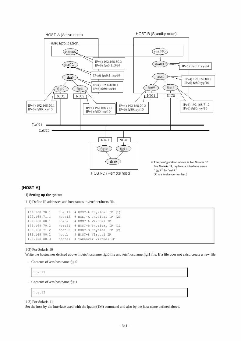
[HOST-A]
1) Setting up the system
1-1) Define IP addresses and hostnames in /etc/inet/hosts file.
192.168.70.1 host11 # HOST-A Physical IP (1)192.168.71.1 host12 # HOST-A Physical IP (2)192.168.80.1 hosta # HOST-A Virtual IP192.168.70.2 host21 # HOST-B Physical IP (1)192.168.71.2 host22 # HOST-B Physical IP (2)192.168.80.2 hostb # HOST-B Virtual IP192.168.80.3 hosta1 # Takeover virtual IP
1-2) For Solaris 10Write the hostnames defined above in /etc/hostname.fjgi0 file and /etc/hostname.fjgi1 file. If a file does not exist, create a new file.
- Contents of /etc/hostname.fjgi0
host11
- Contents of /etc/hostname.fjgi1
host12
1-2) For Solaris 11Set the host by the interface used with the ipadm(1M) command and also by the host name defined above.
- 341 -

- Interface net0
# /usr/sbin/ipadm create-ip net0# /usr/sbin/ipadm create-addr -T static -a host11/24 net0/v4
- Interface net1
# /usr/sbin/ipadm create-ip net1# /usr/sbin/ipadm create-addr -T static -a host12/24 net1/v4
1-3) Define the subnet mask in /etc/inet/netmasks file.
192.168.70.0 255.255.255.0192.168.71.0 255.255.255.0192.168.80.0 255.255.255.0
1-4) Create /etc/inet/ndpd.conf file and set the followings:
ifdefault AdvSendAdvertisements true # Every interface sends a router advertisement.prefix fec0:1::0/64 sha0 # sha0 sends Prefix "fec0:1::0/64".
Note
In the Solaris server that runs Fast switching mode, configure two or more router as IPv6 router. If the IPv6 router breaks down, it cannotuse site-local address to communicate. To prevent this, it is recommended to setup at least two IPv6 routers.For details on /etc/inet/ndpd.conf, refer to the Solaris manual.
1-5) For Solaris 10Create /etc/hostname6.fjgi0 and /etc/hostname6.fjgi1 files as an empty file.
1-5) For Solaris 11Set the interface to be used by using the ipadm(1M) command.
- Interface net0
# /usr/sbin/ipadm create-addr -T addrconf net0/v6
- Interface net1
# /usr/sbin/ipadm create-addr -T addrconf net1/v6
1-6) Define IP addresses and hostnames in /etc/inet/ipnodes file.
fec0:1::3 v6hosta1 # Takeover virtual IP
2) Reboot (For Solaris 10)
Run the following command to reboot the system. Make sure fjgi0 and fjgi1 are enabled as IPv4/IPv6 interfaces after rebooting the system.
# /usr/sbin/shutdown -y -i6 -g0
3) Creation of virtual interface
3-1) For Solaris 10
# /opt/FJSVhanet/usr/sbin/hanetconfig create -n sha0 -m t -i 192.168.80.1 -t fjgi0,fjgi1# /opt/FJSVhanet/usr/sbin/hanetconfig create inet6 -n sha0 -m t -t fjgi0,fjgi1
- 342 -

3-1) For Solaris 11
# /opt/FJSVhanet/usr/sbin/hanetconfig create -n sha0 -m t -i 192.168.80.1 -t net0,net1# /opt/FJSVhanet/usr/sbin/hanetconfig create inet6 -n sha0 -m t -t net0,net1
4) Creation of takeover virtual interface
# /opt/FJSVhanet/usr/sbin/hanethvrsc create -n sha0 -i 192.168.80.3,fec0:1::3/64
[HOST-B]
1) Setting up the system
1-1) Define IP addresses and hostnames in /etc/inet/hosts file. Defined information is the same as for HOST-A.
1-2) For Solaris 10Write the hostnames defined above in /etc/hostname.fjgi0 file and /etc/hostname.fjgi1 file. If a file does not exist, create a new file.
- Contents of /etc/hostname.fjgi0
host21
- Contents of /etc/hostname.fjgi1
host22
1-2) For Solaris 11Set the host by the interface used with the ipadm(1M) command and also by the host name defined above.
- Interface net0
# /usr/sbin/ipadm create-ip net0# /usr/sbin/ipadm create-addr -T static -a host21/24 net0/v4
- Interface net1
# /usr/sbin/ipadm create-ip net1# /usr/sbin/ipadm create-addr -T static -a host22/24 net1/v4
1-3) Define the subnet mask in /etc/inet/netmasks file. Defined content is same as HOST-A.
1-4) Create /etc/inet/ndpd.conf file. Defined information is the same as for HOST-A.
1-5) For Solaris 10Create /etc/hostname6.fjgi0 and /etc/hostname6.fjgi1 files as an empty file.
1-5) For Solaris 11Set the interface to be used by using the ipadm(1M) command.
- Interface net0
# /usr/sbin/ipadm create-addr -T addrconf net0/v6
- Interface net1
# /usr/sbin/ipadm create-addr -T addrconf net1/v6
1-6) Define IP addresses and hostnames in /etc/inet/ipnodes file. Defined content is same as HOST-A.
2) Reboot (For Solaris 10)
Run the following command to reboot the system. Make sure fjgi0 and fjgi1 are enabled as IPv4/IPv6 interfaces after rebooting the system.
- 343 -

# /usr/sbin/shutdown -y -i6 -g0
3) Creation of virtual interface
3-1) For Solaris 10
# /opt/FJSVhanet/usr/sbin/hanetconfig create -n sha0 -m t -i 192.168.80.2 -t fjgi0,fjgi1# /opt/FJSVhanet/usr/sbin/hanetconfig create inet6 -n sha0 -m t -t fjgi0,fjgi1
3-1) For Solaris 11
# /opt/FJSVhanet/usr/sbin/hanetconfig create -n sha0 -m t -i 192.168.80.2 -t net0,net1# /opt/FJSVhanet/usr/sbin/hanetconfig create inet6 -n sha0 -m t -t net0,net1
4) Creation of takeover virtual interface
# /opt/FJSVhanet/usr/sbin/hanethvrsc create -n sha0 -i 192.168.80.3,fec0:1::3/64
[Configuration by RMS Wizard]
1) Configuration of userApplication
After completing step 4) of both HOST-A and HOST-B, connect to the administration server using RMS Wizard, then setup the clusterenvironment.To create Gls resource, select the SysNode for HOST-A and HOST-B. Once Gls is created, register it on the userApplication.When registering on the userApplication, select the SysNode compliant with HOST-A and HOST-B in the order of operation nodefollowed by standby node. Then, register the takeover address "192.168.80.3 - fec0:1::3".
2) Starting of userApplication
After completing the configuration, start the userApplication to activate the takeover virtual interface on the operation node.
B.3.5 Example of the Cluster system (Mutual standby)This section describes an example configuration procedure of the network shown in the diagram below.
The xx, yy in the figure below are assigned automatically by the automatic address configuration.
For configuring the cluster system, refer to the Cluster system manual.In this section, description of private LAN is omitted. The dotted line indicates that the interface is inactive.
Note
When using IPv6 address as a takeover virtual interface, it may take around 30 seconds to recover the communication after switching thenode. In order to hold a communication instantly, start IPv6 routing daemon beforehand on both operating and standby nodes. For detailson this issue, refer to "F.2 Troubleshooting".
- 344 -
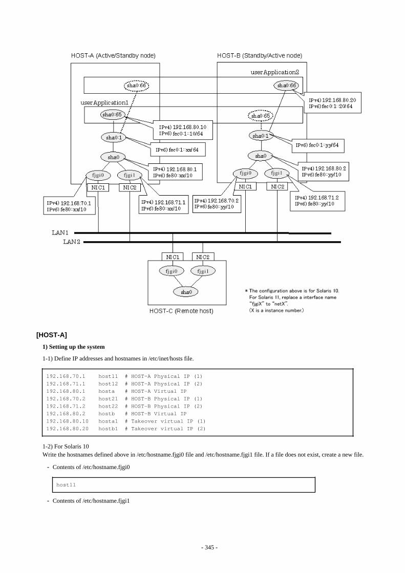
[HOST-A]
1) Setting up the system
1-1) Define IP addresses and hostnames in /etc/inet/hosts file.
192.168.70.1 host11 # HOST-A Physical IP (1)192.168.71.1 host12 # HOST-A Physical IP (2)192.168.80.1 hosta # HOST-A Virtual IP192.168.70.2 host21 # HOST-B Physical IP (1)192.168.71.2 host22 # HOST-B Physical IP (2)192.168.80.2 hostb # HOST-B Virtual IP192.168.80.10 hosta1 # Takeover virtual IP (1)192.168.80.20 hostb1 # Takeover virtual IP (2)
1-2) For Solaris 10Write the hostnames defined above in /etc/hostname.fjgi0 file and /etc/hostname.fjgi1 file. If a file does not exist, create a new file.
- Contents of /etc/hostname.fjgi0
host11
- Contents of /etc/hostname.fjgi1
- 345 -
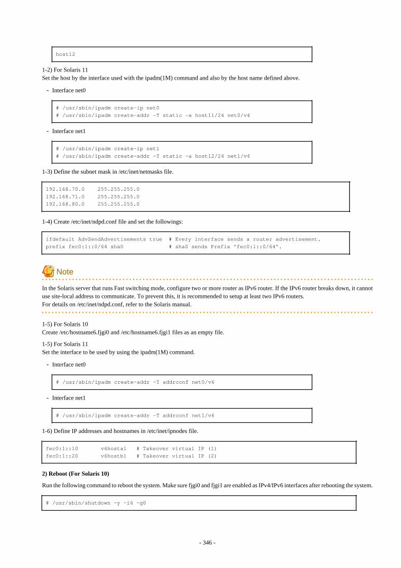
host12
1-2) For Solaris 11Set the host by the interface used with the ipadm(1M) command and also by the host name defined above.
- Interface net0
# /usr/sbin/ipadm create-ip net0# /usr/sbin/ipadm create-addr -T static -a host11/24 net0/v4
- Interface net1
# /usr/sbin/ipadm create-ip net1# /usr/sbin/ipadm create-addr -T static -a host12/24 net1/v4
1-3) Define the subnet mask in /etc/inet/netmasks file.
192.168.70.0 255.255.255.0192.168.71.0 255.255.255.0192.168.80.0 255.255.255.0
1-4) Create /etc/inet/ndpd.conf file and set the followings:
ifdefault AdvSendAdvertisements true # Every interface sends a router advertisement.prefix fec0:1::0/64 sha0 # sha0 sends Prefix "fec0:1::0/64".
Note
In the Solaris server that runs Fast switching mode, configure two or more router as IPv6 router. If the IPv6 router breaks down, it cannotuse site-local address to communicate. To prevent this, it is recommended to setup at least two IPv6 routers.For details on /etc/inet/ndpd.conf, refer to the Solaris manual.
1-5) For Solaris 10Create /etc/hostname6.fjgi0 and /etc/hostname6.fjgi1 files as an empty file.
1-5) For Solaris 11Set the interface to be used by using the ipadm(1M) command.
- Interface net0
# /usr/sbin/ipadm create-addr -T addrconf net0/v6
- Interface net1
# /usr/sbin/ipadm create-addr -T addrconf net1/v6
1-6) Define IP addresses and hostnames in /etc/inet/ipnodes file.
fec0:1::10 v6hosta1 # Takeover virtual IP (1)fec0:1::20 v6hostb1 # Takeover virtual IP (2)
2) Reboot (For Solaris 10)
Run the following command to reboot the system. Make sure fjgi0 and fjgi1 are enabled as IPv4/IPv6 interfaces after rebooting the system.
# /usr/sbin/shutdown -y -i6 -g0
- 346 -

3) Creation of virtual interface
3-1) For Solaris 10
# /opt/FJSVhanet/usr/sbin/hanetconfig create -n sha0 -m t -i 192.168.80.1 -t fjgi0,fjgi1# /opt/FJSVhanet/usr/sbin/hanetconfig create inet6 -n sha0 -m t -t fjgi0,fjgi1
3-1) For Solaris 11
# /opt/FJSVhanet/usr/sbin/hanetconfig create -n sha0 -m t -i 192.168.80.1 -t net0,net1# /opt/FJSVhanet/usr/sbin/hanetconfig create inet6 -n sha0 -m t -t net0,net1
4) Creation of takeover virtual interface
# /opt/FJSVhanet/usr/sbin/hanethvrsc create -n sha0 -i 192.168.80.10,fec0:1::10/64# /opt/FJSVhanet/usr/sbin/hanethvrsc create -n sha0 -i 192.168.80.20,fec0:1::20/64
[HOST-B]
1) Setting up the system
1-1) Define IP addresses and hostnames in /etc/inet/hosts file. Defined information is the same as for HOST-A.
1-2) For Solaris 10Write the hostnames defined above in /etc/hostname.fjgi0 file and /etc/hostname.fjgi1 file. If a file does not exist, create a new file.
- Contents of /etc/hostname.fjgi0
host21
- Contents of /etc/hostname.fjgi1
host22
1-2) For Solaris 11Set the host by the interface used with the ipadm(1M) command and also by the host name defined above.
- Interface net0
# /usr/sbin/ipadm create-ip net0# /usr/sbin/ipadm create-addr -T static -a host21/24 net0/v4
- Interface net1
# /usr/sbin/ipadm create-ip net1# /usr/sbin/ipadm create-addr -T static -a host22/24 net1/v4
1-3) Define the subnet mask in /etc/inet/netmasks file. Defined content is same as HOST-A.
1-4) Create /etc/inet/ndpd.conf file. Defined information is the same as for HOST-A.
1-5) For Solaris 10Create /etc/hostname6.fjgi0 and /etc/hostname6.fjgi1 files as an empty file.
1-5) For Solaris 11Set the interface to be used by using the ipadm(1M) command.
- Interface net0
# /usr/sbin/ipadm create-addr -T addrconf net0/v6
- 347 -
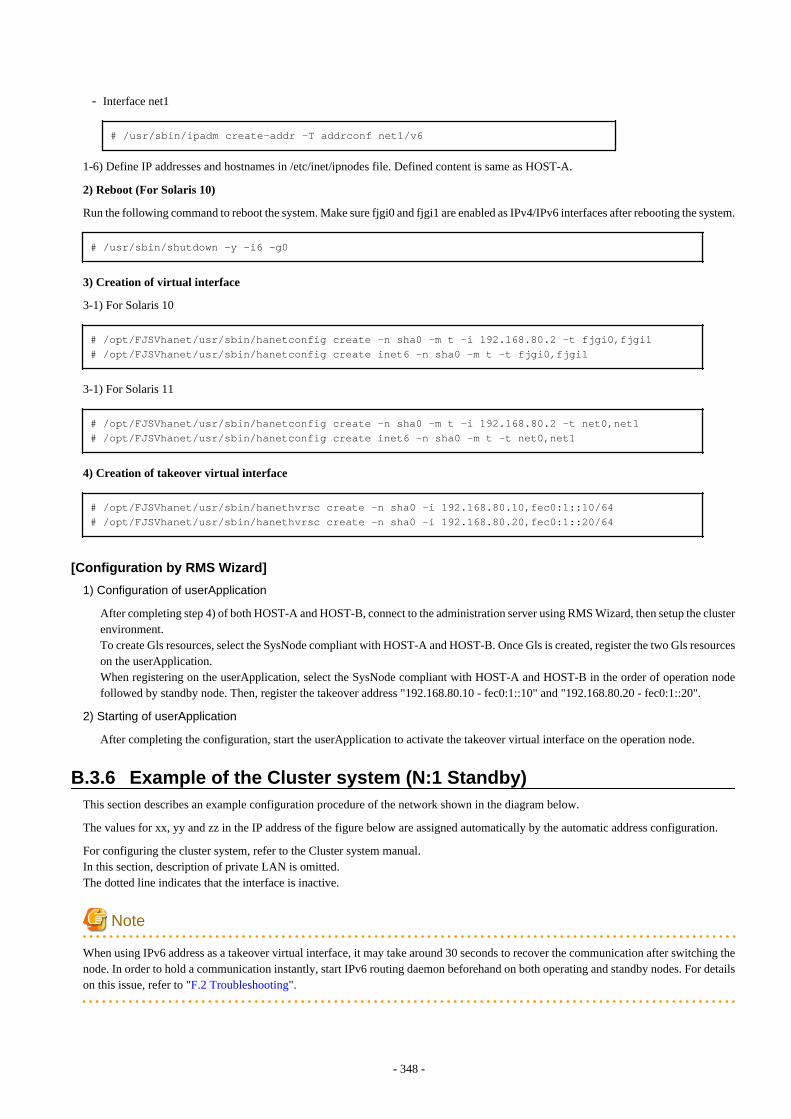
- Interface net1
# /usr/sbin/ipadm create-addr -T addrconf net1/v6
1-6) Define IP addresses and hostnames in /etc/inet/ipnodes file. Defined content is same as HOST-A.
2) Reboot (For Solaris 10)
Run the following command to reboot the system. Make sure fjgi0 and fjgi1 are enabled as IPv4/IPv6 interfaces after rebooting the system.
# /usr/sbin/shutdown -y -i6 -g0
3) Creation of virtual interface
3-1) For Solaris 10
# /opt/FJSVhanet/usr/sbin/hanetconfig create -n sha0 -m t -i 192.168.80.2 -t fjgi0,fjgi1# /opt/FJSVhanet/usr/sbin/hanetconfig create inet6 -n sha0 -m t -t fjgi0,fjgi1
3-1) For Solaris 11
# /opt/FJSVhanet/usr/sbin/hanetconfig create -n sha0 -m t -i 192.168.80.2 -t net0,net1# /opt/FJSVhanet/usr/sbin/hanetconfig create inet6 -n sha0 -m t -t net0,net1
4) Creation of takeover virtual interface
# /opt/FJSVhanet/usr/sbin/hanethvrsc create -n sha0 -i 192.168.80.10,fec0:1::10/64# /opt/FJSVhanet/usr/sbin/hanethvrsc create -n sha0 -i 192.168.80.20,fec0:1::20/64
[Configuration by RMS Wizard]
1) Configuration of userApplication
After completing step 4) of both HOST-A and HOST-B, connect to the administration server using RMS Wizard, then setup the clusterenvironment.To create Gls resources, select the SysNode compliant with HOST-A and HOST-B. Once Gls is created, register the two Gls resourceson the userApplication.When registering on the userApplication, select the SysNode compliant with HOST-A and HOST-B in the order of operation nodefollowed by standby node. Then, register the takeover address "192.168.80.10 - fec0:1::10" and "192.168.80.20 - fec0:1::20".
2) Starting of userApplication
After completing the configuration, start the userApplication to activate the takeover virtual interface on the operation node.
B.3.6 Example of the Cluster system (N:1 Standby)This section describes an example configuration procedure of the network shown in the diagram below.
The values for xx, yy and zz in the IP address of the figure below are assigned automatically by the automatic address configuration.
For configuring the cluster system, refer to the Cluster system manual.In this section, description of private LAN is omitted. The dotted line indicates that the interface is inactive.
Note
When using IPv6 address as a takeover virtual interface, it may take around 30 seconds to recover the communication after switching thenode. In order to hold a communication instantly, start IPv6 routing daemon beforehand on both operating and standby nodes. For detailson this issue, refer to "F.2 Troubleshooting".
- 348 -
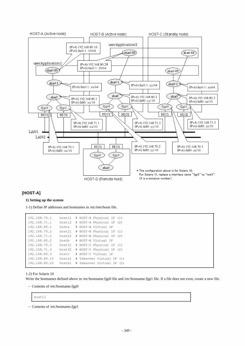
[HOST-A]
1) Setting up the system
1-1) Define IP addresses and hostnames in /etc/inet/hosts file.
192.168.70.1 host11 # HOST-A Physical IP (1)192.168.71.1 host12 # HOST-A Physical IP (2)192.168.80.1 hosta # HOST-A Virtual IP192.168.70.2 host21 # HOST-B Physical IP (1)192.168.71.2 host22 # HOST-B Physical IP (2)192.168.80.2 hostb # HOST-B Virtual IP192.168.70.3 host31 # HOST-C Physical IP (1)192.168.71.3 host32 # HOST-C Physical IP (2)192.168.80.3 hostc # HOST-C Virtual IP192.168.80.10 hosta1 # Takeover virtual IP (1)192.168.80.20 hostb1 # Takeover virtual IP (2)
1-2) For Solaris 10Write the hostnames defined above in /etc/hostname.fjgi0 file and /etc/hostname.fjgi1 file. If a file does not exist, create a new file.
- Contents of /etc/hostname.fjgi0
host11
- Contents of /etc/hostname.fjgi1
- 349 -

host12
1-2) For Solaris 11Set the host by the interface used with the ipadm(1M) command and also by the host name defined above.
- Interface net0
# /usr/sbin/ipadm create-ip net0# /usr/sbin/ipadm create-addr -T static -a host11/24 net0/v4
- Interface net1
# /usr/sbin/ipadm create-ip net1# /usr/sbin/ipadm create-addr -T static -a host12/24 net1/v4
1-3) Define the subnet mask in /etc/inet/netmasks file.
192.168.70.0 255.255.255.0192.168.71.0 255.255.255.0192.168.80.0 255.255.255.0
1-4) Create /etc/inet/ndpd.conf file and set the followings:
ifdefault AdvSendAdvertisements true # Every interface sends a router advertisement.prefix fec0:1::0/64 sha0 # sha0 sends Prefix "fec0:1::0/64".
Note
In the Solaris server that runs Fast switching mode, configure two or more router as IPv6 router. If the IPv6 router breaks down, it cannotuse site-local address to communicate. To prevent this, it is recommended to setup at least two IPv6 routers.For details on /etc/inet/ndpd.conf, refer to the Solaris manual.
1-5) For Solaris 10Create /etc/hostname6.fjgi0 and /etc/hostname6.fjgi1 files as an empty file.
1-5) For Solaris 11Set the interface to be used by using the ipadm(1M) command.
- Interface net0
# /usr/sbin/ipadm create-addr -T addrconf net0/v6
- Interface net1
# /usr/sbin/ipadm create-addr -T addrconf net1/v6
1-6) Define IP addresses and hostnames in /etc/inet/ipnodes file.
fec0:1::10 v6hosta1 # Takeover virtual IP (1)fec0:1::20 v6hostb1 # Takeover virtual IP (2)
2) Reboot (For Solaris 10)
Run the following command to reboot the system. Make sure fjgi0 and fjgi1 are enabled as IPv4/IPv6 interfaces after rebooting the system.
# /usr/sbin/shutdown -y -i6 -g0
- 350 -

3) Creation of virtual interface
3-1) For Solaris 10
# /opt/FJSVhanet/usr/sbin/hanetconfig create -n sha0 -m t -i 192.168.80.1 -t fjgi0,fjgi1# /opt/FJSVhanet/usr/sbin/hanetconfig create inet6 -n sha0 -m t -t fjgi0,fjgi1
3-1) For Solaris 11
# /opt/FJSVhanet/usr/sbin/hanetconfig create -n sha0 -m t -i 192.168.80.1 -t net0,net1# /opt/FJSVhanet/usr/sbin/hanetconfig create inet6 -n sha0 -m t -t net0,net1
4) Creation of takeover virtual interface
# /opt/FJSVhanet/usr/sbin/hanethvrsc create -n sha0 -i 192.168.80.10,fec0:1::10/64
[HOST-B]
1) Setting up the system
1-1) Define IP addresses and hostnames in /etc/inet/hosts file. Defined information is the same as for HOST-A.
1-2) For Solaris 10Write the hostnames defined above in /etc/hostname.fjgi0 file and /etc/hostname.fjgi1 file. If a file does not exist, create a new file.
- Contents of /etc/hostname.fjgi0
host21
- Contents of /etc/hostname.fjgi1
host22
1-2) For Solaris 11Set the host by the interface used with the ipadm(1M) command and also by the host name defined above.
- Interface net0
# /usr/sbin/ipadm create-ip net0# /usr/sbin/ipadm create-addr -T static -a host21/24 net0/v4
- Interface net1
# /usr/sbin/ipadm create-ip net1# /usr/sbin/ipadm create-addr -T static -a host22/24 net1/v4
1-3) Define the subnet mask in /etc/inet/netmasks file. Defined content is same as HOST-A.
1-4) Create /etc/inet/ndpd.conf file. Defined information is the same as for HOST-A.
1-5) For Solaris 10Create /etc/hostname6.fjgi0 and /etc/hostname6.fjgi1 files as an empty file.
1-5) For Solaris 11Set the interface to be used by using the ipadm(1M) command.
- Interface net0
# /usr/sbin/ipadm create-addr -T addrconf net0/v6
- 351 -

- Interface net1
# /usr/sbin/ipadm create-addr -T addrconf net1/v6
1-6) Define IP addresses and hostnames in /etc/inet/ipnodes file. Defined content is same as HOST-A.
2) Reboot (For Solaris 10)
Run the following command to reboot the system. Make sure fjgi0 and fjgi1 are enabled as IPv4/IPv6 interfaces after rebooting the system.
# /usr/sbin/shutdown -y -i6 -g0
3) Creation of virtual interface
3-1) For Solaris 10
# /opt/FJSVhanet/usr/sbin/hanetconfig create -n sha0 -m t -i 192.168.80.2 -t fjgi0,fjgi1# /opt/FJSVhanet/usr/sbin/hanetconfig create inet6 -n sha0 -m t -t fjgi0,fjgi1
3-1) For Solaris 11
# /opt/FJSVhanet/usr/sbin/hanetconfig create -n sha0 -m t -i 192.168.80.2 -t net0,net1# /opt/FJSVhanet/usr/sbin/hanetconfig create inet6 -n sha0 -m t -t net0,net1
4) Creation of takeover virtual interface
# /opt/FJSVhanet/usr/sbin/hanethvrsc create -n sha0 -i 192.168.80.20,fec0:1::20/64
[HOST-C]
1) Setting up the system
1-1) Define IP addresses and hostnames in /etc/inet/hosts file. Defined information is the same as for HOST-A.
1-2) For Solaris 10Write the hostnames defined above in /etc/hostname.fjgi0 file and /etc/hostname.fjgi1 file. If a file does not exist, create a new file.
- Contents of /etc/hostname.fjgi0
host31
- Contents of /etc/hostname.fjgi1
host32
1-2) For Solaris 11Set the host by the interface used with the ipadm(1M) command and also by the host name defined above.
- Interface net0
# /usr/sbin/ipadm create-ip net0# /usr/sbin/ipadm create-addr -T static -a host31/24 net0/v4
- Interface net1
# /usr/sbin/ipadm create-ip net1# /usr/sbin/ipadm create-addr -T static -a host32/24 net1/v4
1-3) Define the subnet mask in /etc/inet/netmasks file. Defined content is same as HOST-A.
- 352 -
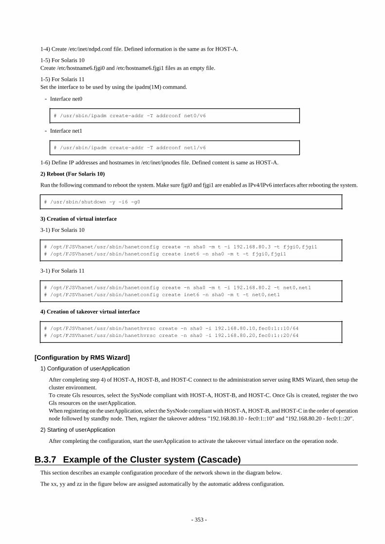
1-4) Create /etc/inet/ndpd.conf file. Defined information is the same as for HOST-A.
1-5) For Solaris 10Create /etc/hostname6.fjgi0 and /etc/hostname6.fjgi1 files as an empty file.
1-5) For Solaris 11Set the interface to be used by using the ipadm(1M) command.
- Interface net0
# /usr/sbin/ipadm create-addr -T addrconf net0/v6
- Interface net1
# /usr/sbin/ipadm create-addr -T addrconf net1/v6
1-6) Define IP addresses and hostnames in /etc/inet/ipnodes file. Defined content is same as HOST-A.
2) Reboot (For Solaris 10)
Run the following command to reboot the system. Make sure fjgi0 and fjgi1 are enabled as IPv4/IPv6 interfaces after rebooting the system.
# /usr/sbin/shutdown -y -i6 -g0
3) Creation of virtual interface
3-1) For Solaris 10
# /opt/FJSVhanet/usr/sbin/hanetconfig create -n sha0 -m t -i 192.168.80.3 -t fjgi0,fjgi1# /opt/FJSVhanet/usr/sbin/hanetconfig create inet6 -n sha0 -m t -t fjgi0,fjgi1
3-1) For Solaris 11
# /opt/FJSVhanet/usr/sbin/hanetconfig create -n sha0 -m t -i 192.168.80.2 -t net0,net1# /opt/FJSVhanet/usr/sbin/hanetconfig create inet6 -n sha0 -m t -t net0,net1
4) Creation of takeover virtual interface
# /opt/FJSVhanet/usr/sbin/hanethvrsc create -n sha0 -i 192.168.80.10,fec0:1::10/64# /opt/FJSVhanet/usr/sbin/hanethvrsc create -n sha0 -i 192.168.80.20,fec0:1::20/64
[Configuration by RMS Wizard]
1) Configuration of userApplication
After completing step 4) of HOST-A, HOST-B, and HOST-C connect to the administration server using RMS Wizard, then setup thecluster environment.To create Gls resources, select the SysNode compliant with HOST-A, HOST-B, and HOST-C. Once Gls is created, register the twoGls resources on the userApplication.When registering on the userApplication, select the SysNode compliant with HOST-A, HOST-B, and HOST-C in the order of operationnode followed by standby node. Then, register the takeover address "192.168.80.10 - fec0:1::10" and "192.168.80.20 - fec0:1::20".
2) Starting of userApplication
After completing the configuration, start the userApplication to activate the takeover virtual interface on the operation node.
B.3.7 Example of the Cluster system (Cascade)This section describes an example configuration procedure of the network shown in the diagram below.
The xx, yy and zz in the figure below are assigned automatically by the automatic address configuration.
- 353 -
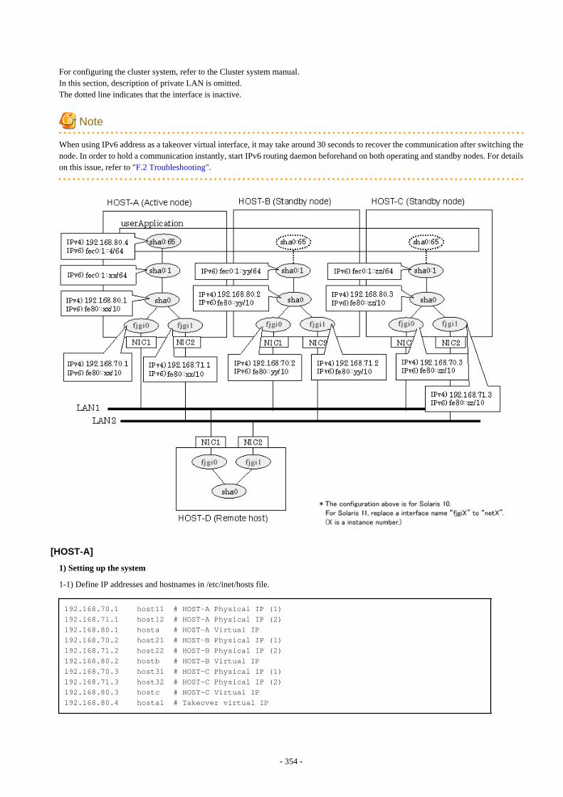
For configuring the cluster system, refer to the Cluster system manual.In this section, description of private LAN is omitted. The dotted line indicates that the interface is inactive.
Note
When using IPv6 address as a takeover virtual interface, it may take around 30 seconds to recover the communication after switching thenode. In order to hold a communication instantly, start IPv6 routing daemon beforehand on both operating and standby nodes. For detailson this issue, refer to "F.2 Troubleshooting".
[HOST-A]
1) Setting up the system
1-1) Define IP addresses and hostnames in /etc/inet/hosts file.
192.168.70.1 host11 # HOST-A Physical IP (1)192.168.71.1 host12 # HOST-A Physical IP (2)192.168.80.1 hosta # HOST-A Virtual IP192.168.70.2 host21 # HOST-B Physical IP (1)192.168.71.2 host22 # HOST-B Physical IP (2)192.168.80.2 hostb # HOST-B Virtual IP192.168.70.3 host31 # HOST-C Physical IP (1)192.168.71.3 host32 # HOST-C Physical IP (2)192.168.80.3 hostc # HOST-C Virtual IP192.168.80.4 hosta1 # Takeover virtual IP
- 354 -

1-2) For Solaris 10Write the hostnames defined above in /etc/hostname.fjgi0 file and /etc/hostname.fjgi1 file. If a file does not exist, create a new file.
- Contents of /etc/hostname.fjgi0
host11
- Contents of /etc/hostname.fjgi1
host12
1-2) For Solaris 11Set the host by the interface used with the ipadm(1M) command and also by the host name defined above.
- Interface net0
# /usr/sbin/ipadm create-ip net0# /usr/sbin/ipadm create-addr -T static -a host11/24 net0/v4
- Interface net1
# /usr/sbin/ipadm create-ip net1# /usr/sbin/ipadm create-addr -T static -a host12/24 net1/v4
1-3) Define the subnet mask in /etc/inet/netmasks file.
192.168.70.0 255.255.255.0192.168.71.0 255.255.255.0192.168.80.0 255.255.255.0
1-4) Create /etc/inet/ndpd.conf file and set the followings:
ifdefault AdvSendAdvertisements true # Every interface sends a router advertisement.prefix fec0:1::0/64 sha0 # sha0 sends Prefix "fec0:1::0/64".
Note
In the Solaris server that runs Fast switching mode, configure two or more router as IPv6 router. If the IPv6 router breaks down, it cannotuse site-local address to communicate. To prevent this, it is recommended to setup at least two IPv6 routers.For details on /etc/inet/ndpd.conf, refer to the Solaris manual.
1-5) For Solaris 10Create /etc/hostname6.fjgi0 and /etc/hostname6.fjgi1 files as an empty file.
1-5) For Solaris 11Set the interface to be used by using the ipadm(1M) command.
- Interface net0
# /usr/sbin/ipadm create-addr -T addrconf net0/v6
- Interface net1
# /usr/sbin/ipadm create-addr -T addrconf net1/v6
1-6) Define IP addresses and hostnames in /etc/inet/ipnodes file.
- 355 -

fec0:1::4 v6hosta1 # Takeover virtual IP
2) Reboot (For Solaris 10)
Run the following command to reboot the system. Make sure fjgi0 and fjgi1 are enabled as IPv4/IPv6 interfaces after rebooting the system.
# /usr/sbin/shutdown -y -i6 -g0
3) Creation of virtual interface
3-1) For Solaris 10
# /opt/FJSVhanet/usr/sbin/hanetconfig create -n sha0 -m t -i 192.168.80.1 -t fjgi0,fjgi1# /opt/FJSVhanet/usr/sbin/hanetconfig create inet6 -n sha0 -m t -t fjgi0,fjgi1
3-1) For Solaris 11
# /opt/FJSVhanet/usr/sbin/hanetconfig create -n sha0 -m t -i 192.168.80.1 -t net0,net1# /opt/FJSVhanet/usr/sbin/hanetconfig create inet6 -n sha0 -m t -t net0,net1
4) Creation of takeover virtual interface
# /opt/FJSVhanet/usr/sbin/hanethvrsc create -n sha0 -i 192.168.80.4,fec0:1::4/64
[HOST-B]
1) Setting up the system
1-1) Define IP addresses and hostnames in /etc/inet/hosts file. Defined information is the same as for HOST-A.
1-2) For Solaris 10
Write the hostnames defined above in /etc/hostname.fjgi0 file and /etc/hostname.fjgi1 file. If a file does not exist, create a new file.
- Contents of /etc/hostname.fjgi0
host21
- Contents of /etc/hostname.fjgi1
host22
1-2) For Solaris 11Set the host by the interface used with the ipadm(1M) command and also by the host name defined above.
- Interface net0
# /usr/sbin/ipadm create-ip net0# /usr/sbin/ipadm create-addr -T static -a host21/24 net0/v4
- Interface net1
# /usr/sbin/ipadm create-ip net1# /usr/sbin/ipadm create-addr -T static -a host22/24 net1/v4
1-3) Define the subnet mask in /etc/inet/netmasks file. Defined content is same as HOST-A.
1-4) Create /etc/inet/ndpd.conf file. Defined information is the same as for HOST-A.
1-5) For Solaris 10Create /etc/hostname6.fjgi0 and /etc/hostname6.fjgi1 files as an empty file.
- 356 -
1-5) For Solaris 11Set the interface to be used by using the ipadm(1M) command.
- Interface net0
# /usr/sbin/ipadm create-addr -T addrconf net0/v6
- Interface net1
# /usr/sbin/ipadm create-addr -T addrconf net1/v6
1-6) Define IP addresses and hostnames in /etc/inet/ipnodes file. Defined content is same as HOST-A.
2) Reboot (For Solaris 10)
Run the following command to reboot the system. Make sure fjgi0 and fjgi1 are enabled as IPv4/IPv6 interfaces after rebooting the system.
# /usr/sbin/shutdown -y -i6 -g0
3) Creation of virtual interface
3-1) For Solaris 10
# /opt/FJSVhanet/usr/sbin/hanetconfig create -n sha0 -m t -i 192.168.80.2 -t fjgi0,fjgi1# /opt/FJSVhanet/usr/sbin/hanetconfig create inet6 -n sha0 -m t -t fjgi0,fjgi1
3-1) For Solaris 11
# /opt/FJSVhanet/usr/sbin/hanetconfig create -n sha0 -m t -i 192.168.80.2 -t net0,net1# /opt/FJSVhanet/usr/sbin/hanetconfig create inet6 -n sha0 -m t -t net0,net1
4) Creation of takeover virtual interface
# /opt/FJSVhanet/usr/sbin/hanethvrsc create -n sha0 -i 192.168.80.4,fec0:1::4/64
[HOST-C]
1) Setting up the system
1-1) Define IP addresses and hostnames in /etc/inet/hosts file. Defined information is the same as for HOST-A.
1-2) For Solaris 10Write the hostnames defined above in /etc/hostname.fjgi0 file and /etc/hostname.fjgi1 file. If a file does not exist, create a new file.
- Contents of /etc/hostname.fjgi0
host31
- Contents of /etc/hostname.fjgi1
host32
1-2) For Solaris 11Set the host by the interface used with the ipadm(1M) command and also by the host name defined above.
- Interface net0
# /usr/sbin/ipadm create-ip net0# /usr/sbin/ipadm create-addr -T static -a host31/24 net0/v4
- 357 -
- Interface net1
# /usr/sbin/ipadm create-ip net1# /usr/sbin/ipadm create-addr -T static -a host32/24 net1/v4
1-3) Define the subnet mask in /etc/inet/netmasks file. Defined content is same as HOST-A.
1-4) Create /etc/inet/ndpd.conf file. Defined information is the same as for HOST-A.
1-5) For Solaris 10Create /etc/hostname6.fjgi0 and /etc/hostname6.fjgi1 files as an empty file.
1-5) For Solaris 11Set the interface to be used by using the ipadm(1M) command.
- Interface net0
# /usr/sbin/ipadm create-addr -T addrconf net0/v6
- Interface net1
# /usr/sbin/ipadm create-addr -T addrconf net1/v6
1-6) Define IP addresses and hostnames in /etc/inet/ipnodes file. Defined content is same as HOST-A.
2) Reboot (For Solaris 10)
Run the following command to reboot the system. Make sure fjgi0 and fjgi1 are enabled as IPv4/IPv6 interfaces after rebooting the system.
# /usr/sbin/shutdown -y -i6 -g0
3) Creation of virtual interface
3-1) For Solaris 10
# /opt/FJSVhanet/usr/sbin/hanetconfig create -n sha0 -m t -i 192.168.80.3 -t fjgi0,fjgi1# /opt/FJSVhanet/usr/sbin/hanetconfig create inet6 -n sha0 -m t -t fjgi0,fjgi1
3-1) For Solaris 11
# /opt/FJSVhanet/usr/sbin/hanetconfig create -n sha0 -m t -i 192.168.80.3 -t net0,net1# /opt/FJSVhanet/usr/sbin/hanetconfig create inet6 -n sha0 -m t -t net0,net1
4) Creation of takeover virtual interface
# /opt/FJSVhanet/usr/sbin/hanethvrsc create -n sha0 -i 192.168.80.4,fec0:1::4/64
[Configuration by RMS Wizard]
1) Configuration of userApplication
After completing step 4) of both HOST-B and HOST-C, connect to the administration server using RMS Wizard, then setup the clusterenvironment.To create Gls resources, select the SysNode compliant with HOST-A, HOST-B, and HOST-C. Once Gls is created, register the twoGls resources on the userApplication.When registering on the userApplication, select the SysNode compliant with HOST-A, HOST-B, and HOST-C in the order of operationnode followed by standby node. Then, register the takeover address "192.168.80.4 - fec0:1::4".
2) Starting of userApplication
After completing the configuration, start the userApplication to activate the takeover virtual interface on the operation node.
- 358 -
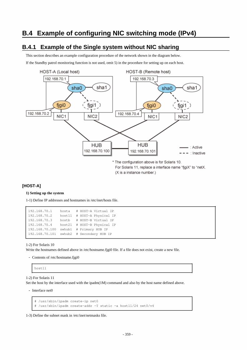
B.4 Example of configuring NIC switching mode (IPv4)
B.4.1 Example of the Single system without NIC sharingThis section describes an example configuration procedure of the network shown in the diagram below.
If the Standby patrol monitoring function is not used, omit 5) in the procedure for setting up on each host.
[HOST-A]
1) Setting up the system
1-1) Define IP addresses and hostnames in /etc/inet/hosts file.
192.168.70.1 hosta # HOST-A Virtual IP192.168.70.2 host11 # HOST-A Physical IP192.168.70.3 hostb # HOST-B Virtual IP192.168.70.4 host21 # HOST-B Physical IP192.168.70.100 swhub1 # Primary HUB IP192.168.70.101 swhub2 # Secondary HUB IP
1-2) For Solaris 10Write the hostnames defined above in /etc/hostname.fjgi0 file. If a file does not exist, create a new file.
- Contents of /etc/hostname.fjgi0
host11
1-2) For Solaris 11Set the host by the interface used with the ipadm(1M) command and also by the host name defined above.
- Interface net0
# /usr/sbin/ipadm create-ip net0# /usr/sbin/ipadm create-addr -T static -a host11/24 net0/v4
1-3) Define the subnet mask in /etc/inet/netmasks file.
- 359 -
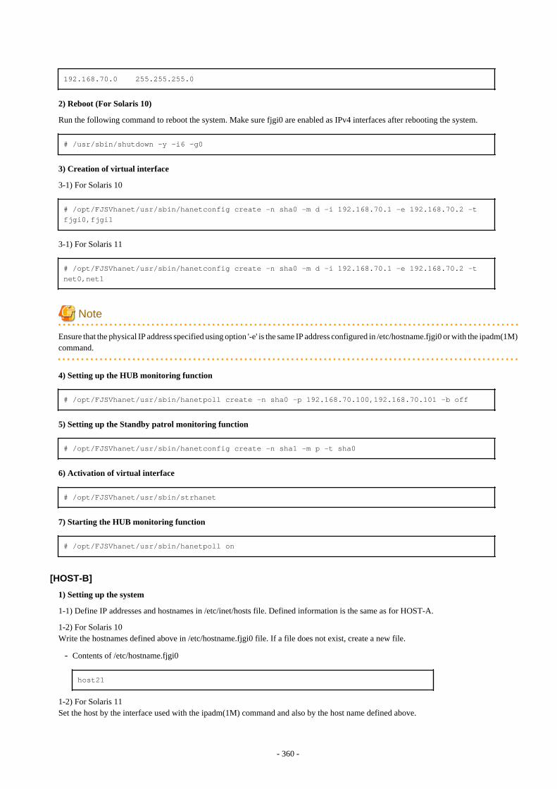
192.168.70.0 255.255.255.0
2) Reboot (For Solaris 10)
Run the following command to reboot the system. Make sure fjgi0 are enabled as IPv4 interfaces after rebooting the system.
# /usr/sbin/shutdown -y -i6 -g0
3) Creation of virtual interface
3-1) For Solaris 10
# /opt/FJSVhanet/usr/sbin/hanetconfig create -n sha0 -m d -i 192.168.70.1 -e 192.168.70.2 -t fjgi0,fjgi1
3-1) For Solaris 11
# /opt/FJSVhanet/usr/sbin/hanetconfig create -n sha0 -m d -i 192.168.70.1 -e 192.168.70.2 -t net0,net1
Note
Ensure that the physical IP address specified using option '-e' is the same IP address configured in /etc/hostname.fjgi0 or with the ipadm(1M)command.
4) Setting up the HUB monitoring function
# /opt/FJSVhanet/usr/sbin/hanetpoll create -n sha0 -p 192.168.70.100,192.168.70.101 -b off
5) Setting up the Standby patrol monitoring function
# /opt/FJSVhanet/usr/sbin/hanetconfig create -n sha1 -m p -t sha0
6) Activation of virtual interface
# /opt/FJSVhanet/usr/sbin/strhanet
7) Starting the HUB monitoring function
# /opt/FJSVhanet/usr/sbin/hanetpoll on
[HOST-B]
1) Setting up the system
1-1) Define IP addresses and hostnames in /etc/inet/hosts file. Defined information is the same as for HOST-A.
1-2) For Solaris 10Write the hostnames defined above in /etc/hostname.fjgi0 file. If a file does not exist, create a new file.
- Contents of /etc/hostname.fjgi0
host21
1-2) For Solaris 11Set the host by the interface used with the ipadm(1M) command and also by the host name defined above.
- 360 -
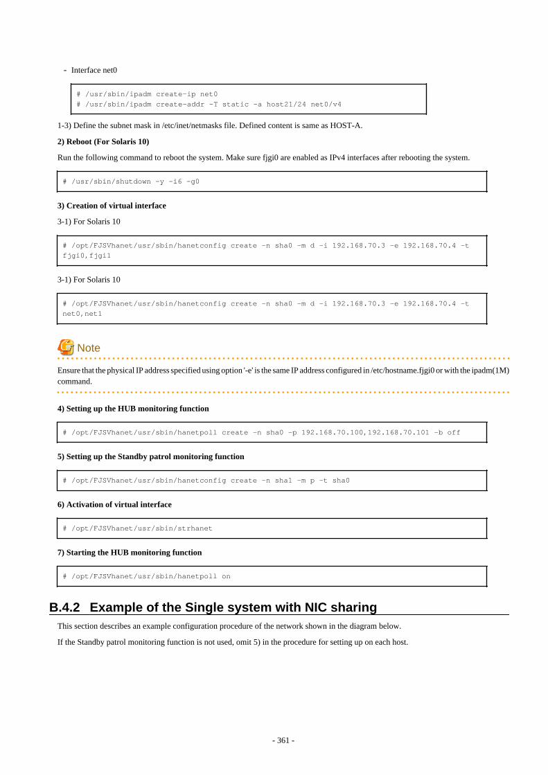
- Interface net0
# /usr/sbin/ipadm create-ip net0# /usr/sbin/ipadm create-addr -T static -a host21/24 net0/v4
1-3) Define the subnet mask in /etc/inet/netmasks file. Defined content is same as HOST-A.
2) Reboot (For Solaris 10)
Run the following command to reboot the system. Make sure fjgi0 are enabled as IPv4 interfaces after rebooting the system.
# /usr/sbin/shutdown -y -i6 -g0
3) Creation of virtual interface
3-1) For Solaris 10
# /opt/FJSVhanet/usr/sbin/hanetconfig create -n sha0 -m d -i 192.168.70.3 -e 192.168.70.4 -t fjgi0,fjgi1
3-1) For Solaris 10
# /opt/FJSVhanet/usr/sbin/hanetconfig create -n sha0 -m d -i 192.168.70.3 -e 192.168.70.4 -t net0,net1
Note
Ensure that the physical IP address specified using option '-e' is the same IP address configured in /etc/hostname.fjgi0 or with the ipadm(1M)command.
4) Setting up the HUB monitoring function
# /opt/FJSVhanet/usr/sbin/hanetpoll create -n sha0 -p 192.168.70.100,192.168.70.101 -b off
5) Setting up the Standby patrol monitoring function
# /opt/FJSVhanet/usr/sbin/hanetconfig create -n sha1 -m p -t sha0
6) Activation of virtual interface
# /opt/FJSVhanet/usr/sbin/strhanet
7) Starting the HUB monitoring function
# /opt/FJSVhanet/usr/sbin/hanetpoll on
B.4.2 Example of the Single system with NIC sharingThis section describes an example configuration procedure of the network shown in the diagram below.
If the Standby patrol monitoring function is not used, omit 5) in the procedure for setting up on each host.
- 361 -
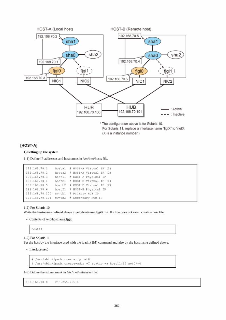
[HOST-A]
1) Setting up the system
1-1) Define IP addresses and hostnames in /etc/inet/hosts file.
192.168.70.1 hosta1 # HOST-A Virtual IP (1)192.168.70.2 hosta2 # HOST-A Virtual IP (2)192.168.70.3 host11 # HOST-A Physical IP192.168.70.4 hostb1 # HOST-B Virtual IP (1)192.168.70.5 hostb2 # HOST-B Virtual IP (2)192.168.70.6 host21 # HOST-B Physical IP192.168.70.100 swhub1 # Primary HUB IP192.168.70.101 swhub2 # Secondary HUB IP
1-2) For Solaris 10Write the hostnames defined above in /etc/hostname.fjgi0 file. If a file does not exist, create a new file.
- Contents of /etc/hostname.fjgi0
host11
1-2) For Solaris 11Set the host by the interface used with the ipadm(1M) command and also by the host name defined above.
- Interface net0
# /usr/sbin/ipadm create-ip net0# /usr/sbin/ipadm create-addr -T static -a host11/24 net0/v4
1-3) Define the subnet mask in /etc/inet/netmasks file.
192.168.70.0 255.255.255.0
- 362 -
2) Reboot (For Solaris 10)
Run the following command to reboot the system. Make sure fjgi0 are enabled as IPv4 interfaces after rebooting the system.
# /usr/sbin/shutdown -y -i6 -g0
3) Creation of virtual interface
3-1) For Solaris 10
# /opt/FJSVhanet/usr/sbin/hanetconfig create -n sha0 -m d -i 192.168.70.1 -e 192.168.70.3 -t fjgi0,fjgi1# /opt/FJSVhanet/usr/sbin/hanetconfig copy -n sha0,sha1 -i 192.168.70.2
3-1) For Solaris 11
# /opt/FJSVhanet/usr/sbin/hanetconfig create -n sha0 -m d -i 192.168.70.1 -e 192.168.70.3 -t net0,net1# /opt/FJSVhanet/usr/sbin/hanetconfig copy -n sha0,sha1 -i 192.168.70.2
Note
Ensure that the physical IP address specified using option '-e' is the same IP address configured in /etc/hostname.fjgi0 with the ipadm(1M)command.
4) Setting up the HUB monitoring function
# /opt/FJSVhanet/usr/sbin/hanetpoll create -n sha0 -p 192.168.70.100,192.168.70.101 -b off# /opt/FJSVhanet/usr/sbin/hanetpoll copy -n sha0,sha1
5) Setting up the Standby patrol monitoring function
# /opt/FJSVhanet/usr/sbin/hanetconfig create -n sha2 -m p -t sha0
6) Activation of virtual interface
# /opt/FJSVhanet/usr/sbin/strhanet
7) Starting the HUB monitoring function
# /opt/FJSVhanet/usr/sbin/hanetpoll on
[HOST-B]
1) Setting up the system
1-1) Define IP addresses and hostnames in /etc/inet/hosts file. Defined information is the same as for HOST-A.
1-2) For Solaris 10Write the hostnames defined above in /etc/hostname.fjgi0 file. If a file does not exist, create a new file.
- Contents of /etc/hostname.fjgi0
host21
1-2) For Solaris 11Set the host by the interface used with the ipadm(1M) command and also by the host name defined above.
- 363 -
- Interface net0
# /usr/sbin/ipadm create-ip net0# /usr/sbin/ipadm create-addr -T static -a host21/24 net0/v4
1-3) Define the subnet mask in /etc/inet/netmasks file. Defined content is same as HOST-A.
2) Reboot (For Solaris 10)
Run the following command to reboot the system. Make sure fjgi0 are enabled as IPv4 interfaces after rebooting the system.
# /usr/sbin/shutdown -y -i6 -g0
3) Creation of virtual interface
3-1) For Solaris 10
# /opt/FJSVhanet/usr/sbin/hanetconfig create -n sha0 -m d -i 192.168.70.4 -e 192.168.70.6 -t fjgi0,fjgi1# /opt/FJSVhanet/usr/sbin/hanetconfig copy -n sha0,sha1 -i 192.168.70.5
3-1) For Solaris 11
# /opt/FJSVhanet/usr/sbin/hanetconfig create -n sha0 -m d -i 192.168.70.4 -e 192.168.70.6 -t net0,net1# /opt/FJSVhanet/usr/sbin/hanetconfig copy -n sha0,sha1 -i 192.168.70.5
Note
Ensure that the physical IP address specified using option '-e' is the same IP address configured in /etc/hostname.fjgi0 with the ipadm(1M)command.
4) Setting up the HUB monitoring function
# /opt/FJSVhanet/usr/sbin/hanetpoll create -n sha0 -p 192.168.70.100,192.168.70.101 -b off# /opt/FJSVhanet/usr/sbin/hanetpoll copy -n sha0,sha1
5) Setting up the Standby patrol monitoring function
# /opt/FJSVhanet/usr/sbin/hanetconfig create -n sha2 -m p -t sha0
6) Activation of virtual interface
# /opt/FJSVhanet/usr/sbin/strhanet
7) Starting the HUB monitoring function
# /opt/FJSVhanet/usr/sbin/hanetpoll on
B.4.3 Example of the Single system in Physical IP address takeoverfunction
This section describes an example configuration procedure of the network shown in the diagram below.
If the Standby patrol monitoring function is not used, omit 5) in the procedure for setting up on each host.
- 364 -
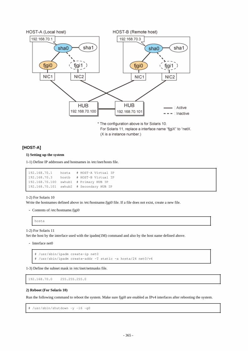
[HOST-A]
1) Setting up the system
1-1) Define IP addresses and hostnames in /etc/inet/hosts file.
192.168.70.1 hosta # HOST-A Virtual IP192.168.70.3 hostb # HOST-B Virtual IP192.168.70.100 swhub1 # Primary HUB IP192.168.70.101 swhub2 # Secondary HUB IP
1-2) For Solaris 10Write the hostnames defined above in /etc/hostname.fjgi0 file. If a file does not exist, create a new file.
- Contents of /etc/hostname.fjgi0
hosta
1-2) For Solaris 11Set the host by the interface used with the ipadm(1M) command and also by the host name defined above.
- Interface net0
# /usr/sbin/ipadm create-ip net0# /usr/sbin/ipadm create-addr -T static -a hosta/24 net0/v4
1-3) Define the subnet mask in /etc/inet/netmasks file.
192.168.70.0 255.255.255.0
2) Reboot (For Solaris 10)
Run the following command to reboot the system. Make sure fjgi0 are enabled as IPv4 interfaces after rebooting the system.
# /usr/sbin/shutdown -y -i6 -g0
- 365 -
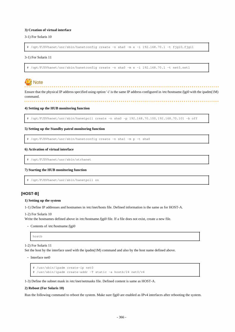
3) Creation of virtual interface
3-1) For Solaris 10
# /opt/FJSVhanet/usr/sbin/hanetconfig create -n sha0 -m e -i 192.168.70.1 -t fjgi0,fjgi1
3-1) For Solaris 11
# /opt/FJSVhanet/usr/sbin/hanetconfig create -n sha0 -m e -i 192.168.70.1 -t net0,net1
Note
Ensure that the physical IP address specified using option '-i' is the same IP address configured in /etc/hostname.fjgi0 with the ipadm(1M)command.
4) Setting up the HUB monitoring function
# /opt/FJSVhanet/usr/sbin/hanetpoll create -n sha0 -p 192.168.70.100,192.168.70.101 -b off
5) Setting up the Standby patrol monitoring function
# /opt/FJSVhanet/usr/sbin/hanetconfig create -n sha1 -m p -t sha0
6) Activation of virtual interface
# /opt/FJSVhanet/usr/sbin/strhanet
7) Starting the HUB monitoring function
# /opt/FJSVhanet/usr/sbin/hanetpoll on
[HOST-B]
1) Setting up the system
1-1) Define IP addresses and hostnames in /etc/inet/hosts file. Defined information is the same as for HOST-A.
1-2) For Solaris 10Write the hostnames defined above in /etc/hostname.fjgi0 file. If a file does not exist, create a new file.
- Contents of /etc/hostname.fjgi0
hostb
1-2) For Solaris 11Set the host by the interface used with the ipadm(1M) command and also by the host name defined above.
- Interface net0
# /usr/sbin/ipadm create-ip net0# /usr/sbin/ipadm create-addr -T static -a hostb/24 net0/v4
1-3) Define the subnet mask in /etc/inet/netmasks file. Defined content is same as HOST-A.
2) Reboot (For Solaris 10)
Run the following command to reboot the system. Make sure fjgi0 are enabled as IPv4 interfaces after rebooting the system.
- 366 -
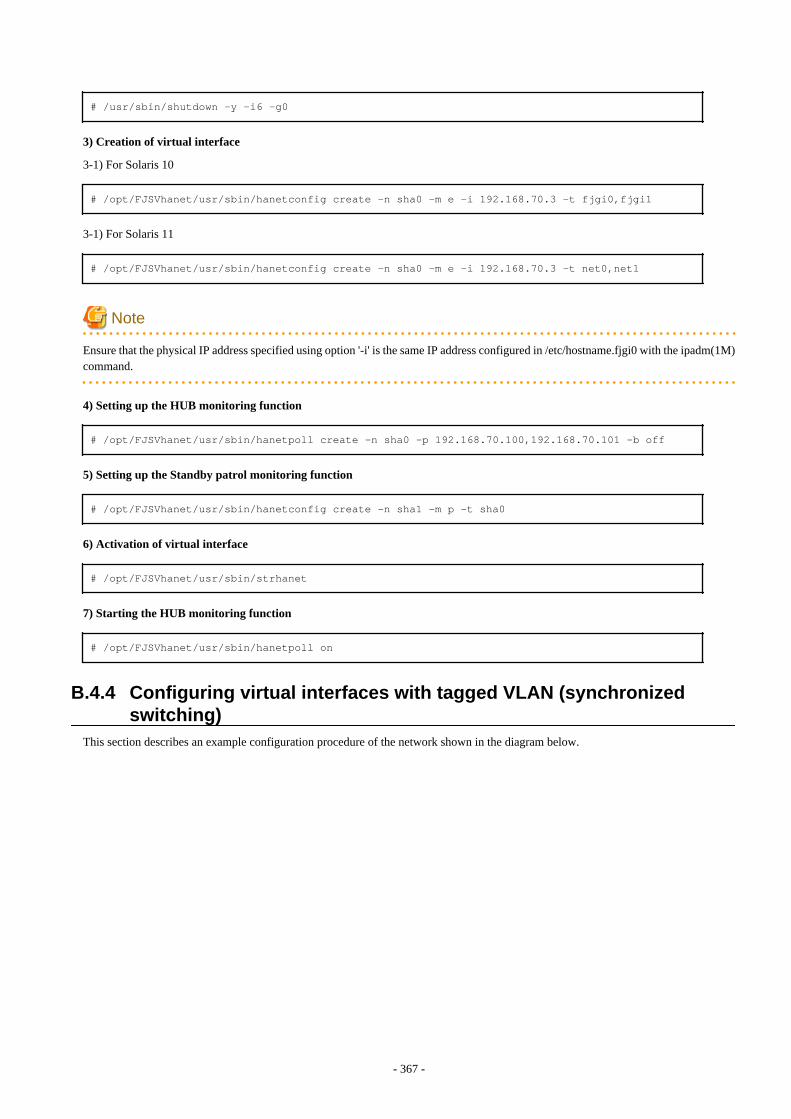
# /usr/sbin/shutdown -y -i6 -g0
3) Creation of virtual interface
3-1) For Solaris 10
# /opt/FJSVhanet/usr/sbin/hanetconfig create -n sha0 -m e -i 192.168.70.3 -t fjgi0,fjgi1
3-1) For Solaris 11
# /opt/FJSVhanet/usr/sbin/hanetconfig create -n sha0 -m e -i 192.168.70.3 -t net0,net1
Note
Ensure that the physical IP address specified using option '-i' is the same IP address configured in /etc/hostname.fjgi0 with the ipadm(1M)command.
4) Setting up the HUB monitoring function
# /opt/FJSVhanet/usr/sbin/hanetpoll create -n sha0 -p 192.168.70.100,192.168.70.101 -b off
5) Setting up the Standby patrol monitoring function
# /opt/FJSVhanet/usr/sbin/hanetconfig create -n sha1 -m p -t sha0
6) Activation of virtual interface
# /opt/FJSVhanet/usr/sbin/strhanet
7) Starting the HUB monitoring function
# /opt/FJSVhanet/usr/sbin/hanetpoll on
B.4.4 Configuring virtual interfaces with tagged VLAN (synchronizedswitching)
This section describes an example configuration procedure of the network shown in the diagram below.
- 367 -
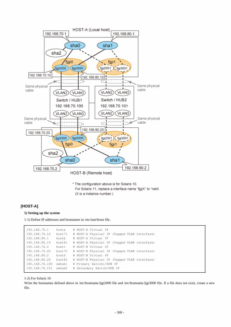
[HOST-A]
1) Setting up the system
1-1) Define IP addresses and hostnames in /etc/inet/hosts file.
192.168.70.1 hosta # HOST-A Virtual IP192.168.70.10 host71 # HOST-A Physical IP (Tagged VLAN interface)192.168.80.1 hostb # HOST-A Virtual IP192.168.80.10 host81 # HOST-A Physical IP (Tagged VLAN interface)192.168.70.2 hostc # HOST-B Virtual IP192.168.70.20 host72 # HOST-B Physical IP (Tagged VLAN interface)192.168.80.2 hostd # HOST-B Virtual IP192.168.80.20 host82 # HOST-B Physical IP (Tagged VLAN interface)192.168.70.100 swhub1 # Primary Switchi/HUB IP192.168.70.101 swhub2 # Secondary Switch/HUB IP
1-2) For Solaris 10Write the hostnames defined above in /etc/hostname.fjgi2000 file and /etc/hostname.fjgi3000 file. If a file does not exist, create a newfile.
- 368 -
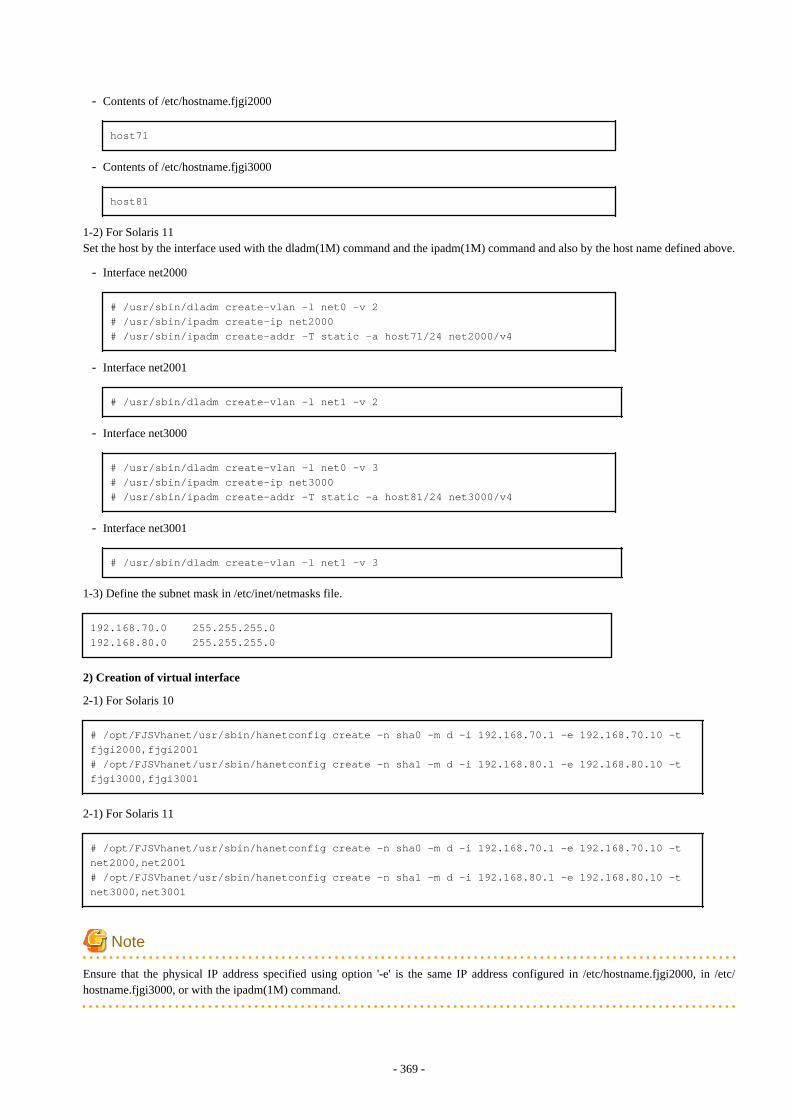
- Contents of /etc/hostname.fjgi2000
host71
- Contents of /etc/hostname.fjgi3000
host81
1-2) For Solaris 11Set the host by the interface used with the dladm(1M) command and the ipadm(1M) command and also by the host name defined above.
- Interface net2000
# /usr/sbin/dladm create-vlan -l net0 -v 2# /usr/sbin/ipadm create-ip net2000# /usr/sbin/ipadm create-addr -T static -a host71/24 net2000/v4
- Interface net2001
# /usr/sbin/dladm create-vlan -l net1 -v 2
- Interface net3000
# /usr/sbin/dladm create-vlan -l net0 -v 3# /usr/sbin/ipadm create-ip net3000# /usr/sbin/ipadm create-addr -T static -a host81/24 net3000/v4
- Interface net3001
# /usr/sbin/dladm create-vlan -l net1 -v 3
1-3) Define the subnet mask in /etc/inet/netmasks file.
192.168.70.0 255.255.255.0192.168.80.0 255.255.255.0
2) Creation of virtual interface
2-1) For Solaris 10
# /opt/FJSVhanet/usr/sbin/hanetconfig create -n sha0 -m d -i 192.168.70.1 -e 192.168.70.10 -t fjgi2000,fjgi2001# /opt/FJSVhanet/usr/sbin/hanetconfig create -n sha1 -m d -i 192.168.80.1 -e 192.168.80.10 -t fjgi3000,fjgi3001
2-1) For Solaris 11
# /opt/FJSVhanet/usr/sbin/hanetconfig create -n sha0 -m d -i 192.168.70.1 -e 192.168.70.10 -t net2000,net2001# /opt/FJSVhanet/usr/sbin/hanetconfig create -n sha1 -m d -i 192.168.80.1 -e 192.168.80.10 -t net3000,net3001
Note
Ensure that the physical IP address specified using option '-e' is the same IP address configured in /etc/hostname.fjgi2000, in /etc/hostname.fjgi3000, or with the ipadm(1M) command.
- 369 -
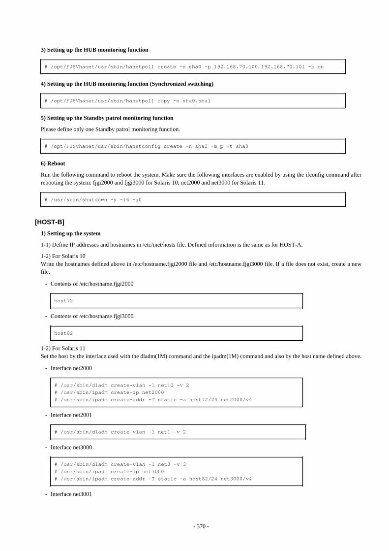
3) Setting up the HUB monitoring function
# /opt/FJSVhanet/usr/sbin/hanetpoll create -n sha0 -p 192.168.70.100,192.168.70.101 -b on
4) Setting up the HUB monitoring function (Synchronized switching)
# /opt/FJSVhanet/usr/sbin/hanetpoll copy -n sha0,sha1
5) Setting up the Standby patrol monitoring function
Please define only one Standby patrol monitoring function.
# /opt/FJSVhanet/usr/sbin/hanetconfig create -n sha2 -m p -t sha0
6) Reboot
Run the following command to reboot the system. Make sure the following interfaces are enabled by using the ifconfig command afterrebooting the system: fjgi2000 and fjgi3000 for Solaris 10; net2000 and net3000 for Solaris 11.
# /usr/sbin/shutdown -y -i6 -g0
[HOST-B]
1) Setting up the system
1-1) Define IP addresses and hostnames in /etc/inet/hosts file. Defined information is the same as for HOST-A.
1-2) For Solaris 10Write the hostnames defined above in /etc/hostname.fjgi2000 file and /etc/hostname.fjgi3000 file. If a file does not exist, create a newfile.
- Contents of /etc/hostname.fjgi2000
host72
- Contents of /etc/hostname.fjgi3000
host82
1-2) For Solaris 11Set the host by the interface used with the dladm(1M) command and the ipadm(1M) command and also by the host name defined above.
- Interface net2000
# /usr/sbin/dladm create-vlan -l neti0 -v 2# /usr/sbin/ipadm create-ip net2000# /usr/sbin/ipadm create-addr -T static -a host72/24 net2000/v4
- Interface net2001
# /usr/sbin/dladm create-vlan -l net1 -v 2
- Interface net3000
# /usr/sbin/dladm create-vlan -l net0 -v 3# /usr/sbin/ipadm create-ip net3000# /usr/sbin/ipadm create-addr -T static -a host82/24 net3000/v4
- Interface net3001
- 370 -
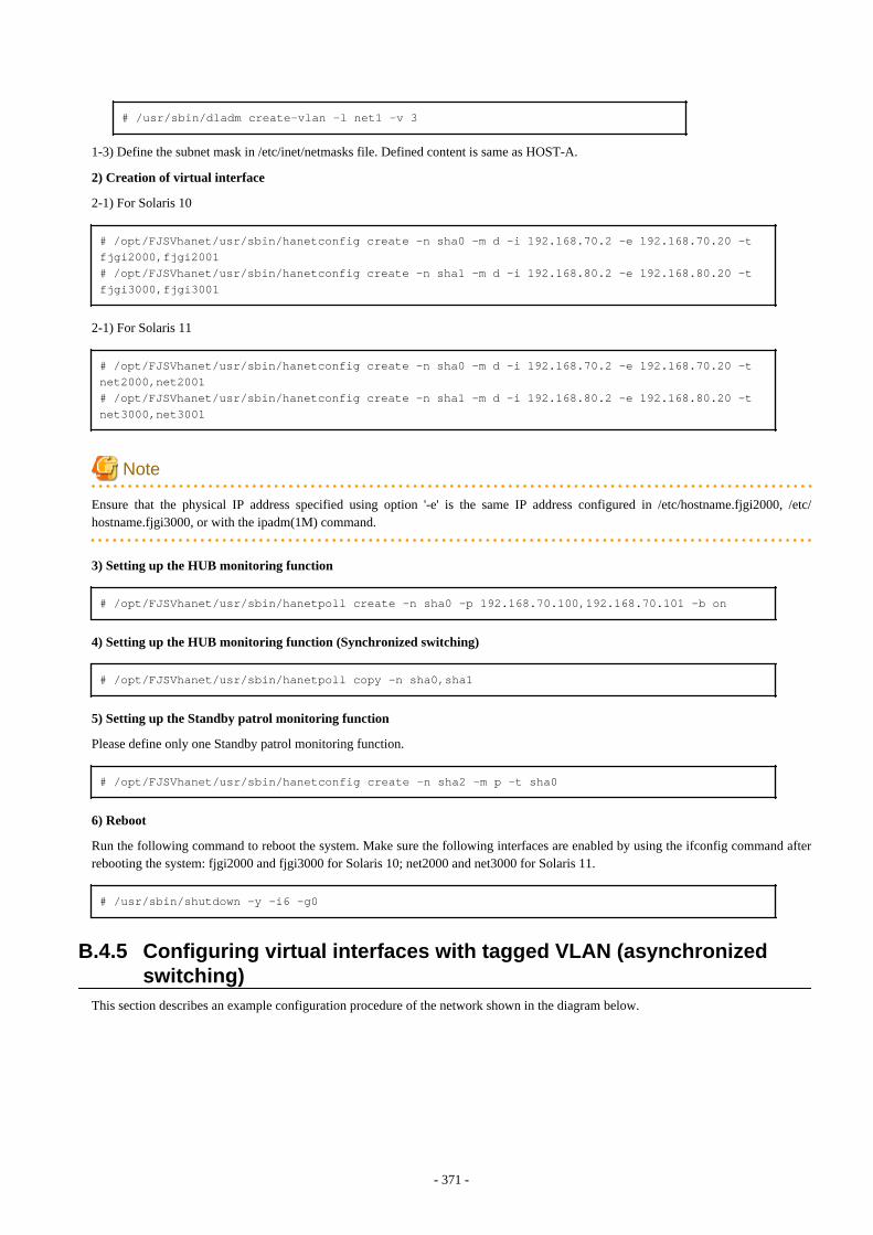
# /usr/sbin/dladm create-vlan -l net1 -v 3
1-3) Define the subnet mask in /etc/inet/netmasks file. Defined content is same as HOST-A.
2) Creation of virtual interface
2-1) For Solaris 10
# /opt/FJSVhanet/usr/sbin/hanetconfig create -n sha0 -m d -i 192.168.70.2 -e 192.168.70.20 -t fjgi2000,fjgi2001# /opt/FJSVhanet/usr/sbin/hanetconfig create -n sha1 -m d -i 192.168.80.2 -e 192.168.80.20 -t fjgi3000,fjgi3001
2-1) For Solaris 11
# /opt/FJSVhanet/usr/sbin/hanetconfig create -n sha0 -m d -i 192.168.70.2 -e 192.168.70.20 -t net2000,net2001# /opt/FJSVhanet/usr/sbin/hanetconfig create -n sha1 -m d -i 192.168.80.2 -e 192.168.80.20 -t net3000,net3001
Note
Ensure that the physical IP address specified using option '-e' is the same IP address configured in /etc/hostname.fjgi2000, /etc/hostname.fjgi3000, or with the ipadm(1M) command.
3) Setting up the HUB monitoring function
# /opt/FJSVhanet/usr/sbin/hanetpoll create -n sha0 -p 192.168.70.100,192.168.70.101 -b on
4) Setting up the HUB monitoring function (Synchronized switching)
# /opt/FJSVhanet/usr/sbin/hanetpoll copy -n sha0,sha1
5) Setting up the Standby patrol monitoring function
Please define only one Standby patrol monitoring function.
# /opt/FJSVhanet/usr/sbin/hanetconfig create -n sha2 -m p -t sha0
6) Reboot
Run the following command to reboot the system. Make sure the following interfaces are enabled by using the ifconfig command afterrebooting the system: fjgi2000 and fjgi3000 for Solaris 10; net2000 and net3000 for Solaris 11.
# /usr/sbin/shutdown -y -i6 -g0
B.4.5 Configuring virtual interfaces with tagged VLAN (asynchronizedswitching)
This section describes an example configuration procedure of the network shown in the diagram below.
- 371 -
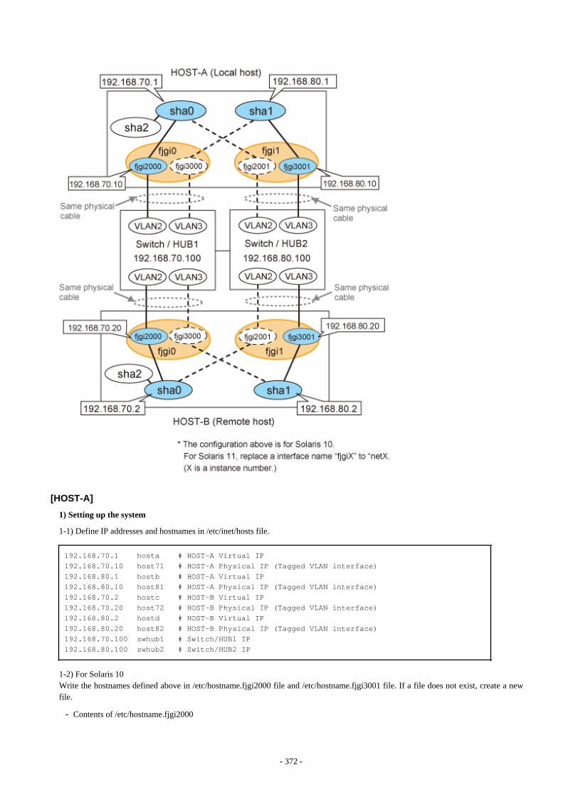
[HOST-A]
1) Setting up the system
1-1) Define IP addresses and hostnames in /etc/inet/hosts file.
192.168.70.1 hosta # HOST-A Virtual IP192.168.70.10 host71 # HOST-A Physical IP (Tagged VLAN interface)192.168.80.1 hostb # HOST-A Virtual IP192.168.80.10 host81 # HOST-A Physical IP (Tagged VLAN interface)192.168.70.2 hostc # HOST-B Virtual IP192.168.70.20 host72 # HOST-B Physical IP (Tagged VLAN interface)192.168.80.2 hostd # HOST-B Virtual IP192.168.80.20 host82 # HOST-B Physical IP (Tagged VLAN interface)192.168.70.100 swhub1 # Switch/HUB1 IP192.168.80.100 swhub2 # Switch/HUB2 IP
1-2) For Solaris 10Write the hostnames defined above in /etc/hostname.fjgi2000 file and /etc/hostname.fjgi3001 file. If a file does not exist, create a newfile.
- Contents of /etc/hostname.fjgi2000
- 372 -
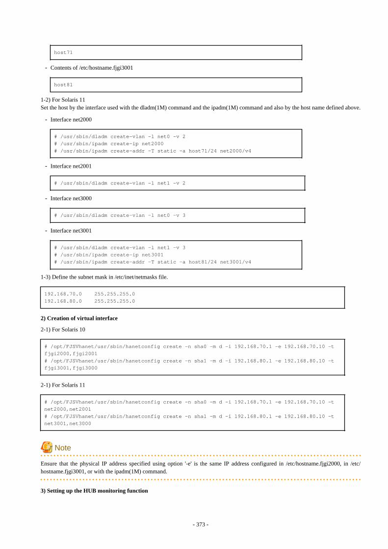
host71
- Contents of /etc/hostname.fjgi3001
host81
1-2) For Solaris 11Set the host by the interface used with the dladm(1M) command and the ipadm(1M) command and also by the host name defined above.
- Interface net2000
# /usr/sbin/dladm create-vlan -l net0 -v 2# /usr/sbin/ipadm create-ip net2000# /usr/sbin/ipadm create-addr -T static -a host71/24 net2000/v4
- Interface net2001
# /usr/sbin/dladm create-vlan -l net1 -v 2
- Interface net3000
# /usr/sbin/dladm create-vlan -l net0 -v 3
- Interface net3001
# /usr/sbin/dladm create-vlan -l net1 -v 3# /usr/sbin/ipadm create-ip net3001# /usr/sbin/ipadm create-addr -T static -a host81/24 net3001/v4
1-3) Define the subnet mask in /etc/inet/netmasks file.
192.168.70.0 255.255.255.0192.168.80.0 255.255.255.0
2) Creation of virtual interface
2-1) For Solaris 10
# /opt/FJSVhanet/usr/sbin/hanetconfig create -n sha0 -m d -i 192.168.70.1 -e 192.168.70.10 -t fjgi2000,fjgi2001# /opt/FJSVhanet/usr/sbin/hanetconfig create -n sha1 -m d -i 192.168.80.1 -e 192.168.80.10 -t fjgi3001,fjgi3000
2-1) For Solaris 11
# /opt/FJSVhanet/usr/sbin/hanetconfig create -n sha0 -m d -i 192.168.70.1 -e 192.168.70.10 -t net2000,net2001# /opt/FJSVhanet/usr/sbin/hanetconfig create -n sha1 -m d -i 192.168.80.1 -e 192.168.80.10 -t net3001,net3000
Note
Ensure that the physical IP address specified using option '-e' is the same IP address configured in /etc/hostname.fjgi2000, in /etc/hostname.fjgi3001, or with the ipadm(1M) command.
3) Setting up the HUB monitoring function
- 373 -
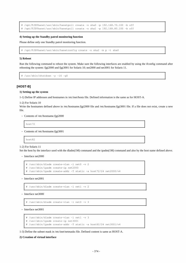
# /opt/FJSVhanet/usr/sbin/hanetpoll create -n sha0 -p 192.168.70.100 -b off# /opt/FJSVhanet/usr/sbin/hanetpoll create -n sha1 -p 192.168.80.100 -b off
4) Setting up the Standby patrol monitoring function
Please define only one Standby patrol monitoring function.
# /opt/FJSVhanet/usr/sbin/hanetconfig create -n sha2 -m p -t sha0
5) Reboot
Run the following command to reboot the system. Make sure the following interfaces are enabled by using the ifconfig command afterrebooting the system: fjgi2000 and fjgi3001 for Solaris 10; net2000 and net3001 for Solaris 11.
# /usr/sbin/shutdown -y -i6 -g0
[HOST-B]
1) Setting up the system
1-1) Define IP addresses and hostnames in /etc/inet/hosts file. Defined information is the same as for HOST-A.
1-2) For Solaris 10Write the hostnames defined above in /etc/hostname.fjgi2000 file and /etc/hostname.fjgi3001 file. If a file does not exist, create a newfile.
- Contents of /etc/hostname.fjgi2000
host72
- Contents of /etc/hostname.fjgi3001
host82
1-2) For Solaris 11Set the host by the interface used with the dladm(1M) command and the ipadm(1M) command and also by the host name defined above.
- Interface net2000
# /usr/sbin/dladm create-vlan -l net0 -v 2# /usr/sbin/ipadm create-ip net2000# /usr/sbin/ipadm create-addr -T static -a host72/24 net2000/v4
- Interface net2001
# /usr/sbin/dladm create-vlan -l net1 -v 2
- Interface net3000
# /usr/sbin/dladm create-vlan -l net0 -v 3
- Interface net3001
# /usr/sbin/dladm create-vlan -l net1 -v 3# /usr/sbin/ipadm create-ip net3001# /usr/sbin/ipadm create-addr -T static -a host82/24 net3001/v4
1-3) Define the subnet mask in /etc/inet/netmasks file. Defined content is same as HOST-A.
2) Creation of virtual interface
- 374 -

2-1) For Solaris 10
# /opt/FJSVhanet/usr/sbin/hanetconfig create -n sha0 -m d -i 192.168.70.2 -e 192.168.70.20 -t fjgi2000,fjgi2001# /opt/FJSVhanet/usr/sbin/hanetconfig create -n sha1 -m d -i 192.168.80.2 -e 192.168.80.20 -t fjgi3001,fjgi3000
2-1) For Solaris 11
# /opt/FJSVhanet/usr/sbin/hanetconfig create -n sha0 -m d -i 192.168.70.2 -e 192.168.70.20 -t net2000,net2001# /opt/FJSVhanet/usr/sbin/hanetconfig create -n sha1 -m d -i 192.168.80.2 -e 192.168.80.20 -t net3001,net3000
Note
Ensure that the physical IP address specified using option '-e' is the same IP address configured in /etc/hostname.fjgi2000, in /etc/hostname.fjgi3001, or with the ipadm(1M) command.
3) Setting up the HUB monitoring function
# /opt/FJSVhanet/usr/sbin/hanetpoll create -n sha0 -p 192.168.70.100 -b off# /opt/FJSVhanet/usr/sbin/hanetpoll create -n sha1 -p 192.168.80.100 -b off
4) Setting up the Standby patrol monitoring function
Please define only one Standby patrol monitoring function.
# /opt/FJSVhanet/usr/sbin/hanetconfig create -n sha2 -m p -t sha0
5) Reboot
Run the following command to reboot the system. Make sure the following interfaces are enabled by using the ifconfig command afterrebooting the system: fjgi2000 and fjgi3001 for Solaris 10; net2000 and net3001 for Solaris 11.
# /usr/sbin/shutdown -y -i6 -g0
B.4.6 Example of the Cluster system (1:1 Standby)This section describes an example configuration procedure of the network shown in the diagram below.
For configuring the cluster system, refer to the Cluster system manual.In this section, description of private LAN is omitted. The dotted line indicates that the interface is inactive.
If the Standby patrol monitoring function is not used, omit 5) and 8) in the procedure for setting up on each host.
- 375 -
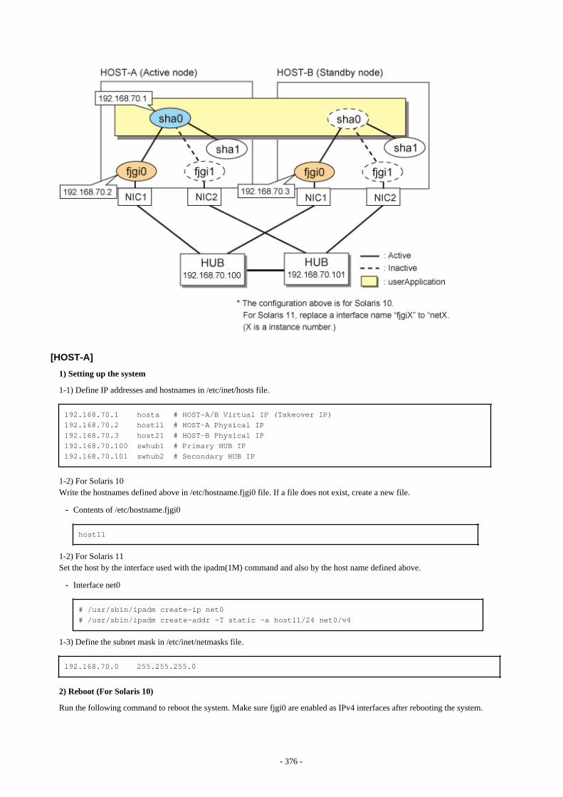
[HOST-A]
1) Setting up the system
1-1) Define IP addresses and hostnames in /etc/inet/hosts file.
192.168.70.1 hosta # HOST-A/B Virtual IP (Takeover IP)192.168.70.2 host11 # HOST-A Physical IP192.168.70.3 host21 # HOST-B Physical IP192.168.70.100 swhub1 # Primary HUB IP192.168.70.101 swhub2 # Secondary HUB IP
1-2) For Solaris 10Write the hostnames defined above in /etc/hostname.fjgi0 file. If a file does not exist, create a new file.
- Contents of /etc/hostname.fjgi0
host11
1-2) For Solaris 11Set the host by the interface used with the ipadm(1M) command and also by the host name defined above.
- Interface net0
# /usr/sbin/ipadm create-ip net0# /usr/sbin/ipadm create-addr -T static -a host11/24 net0/v4
1-3) Define the subnet mask in /etc/inet/netmasks file.
192.168.70.0 255.255.255.0
2) Reboot (For Solaris 10)
Run the following command to reboot the system. Make sure fjgi0 are enabled as IPv4 interfaces after rebooting the system.
- 376 -
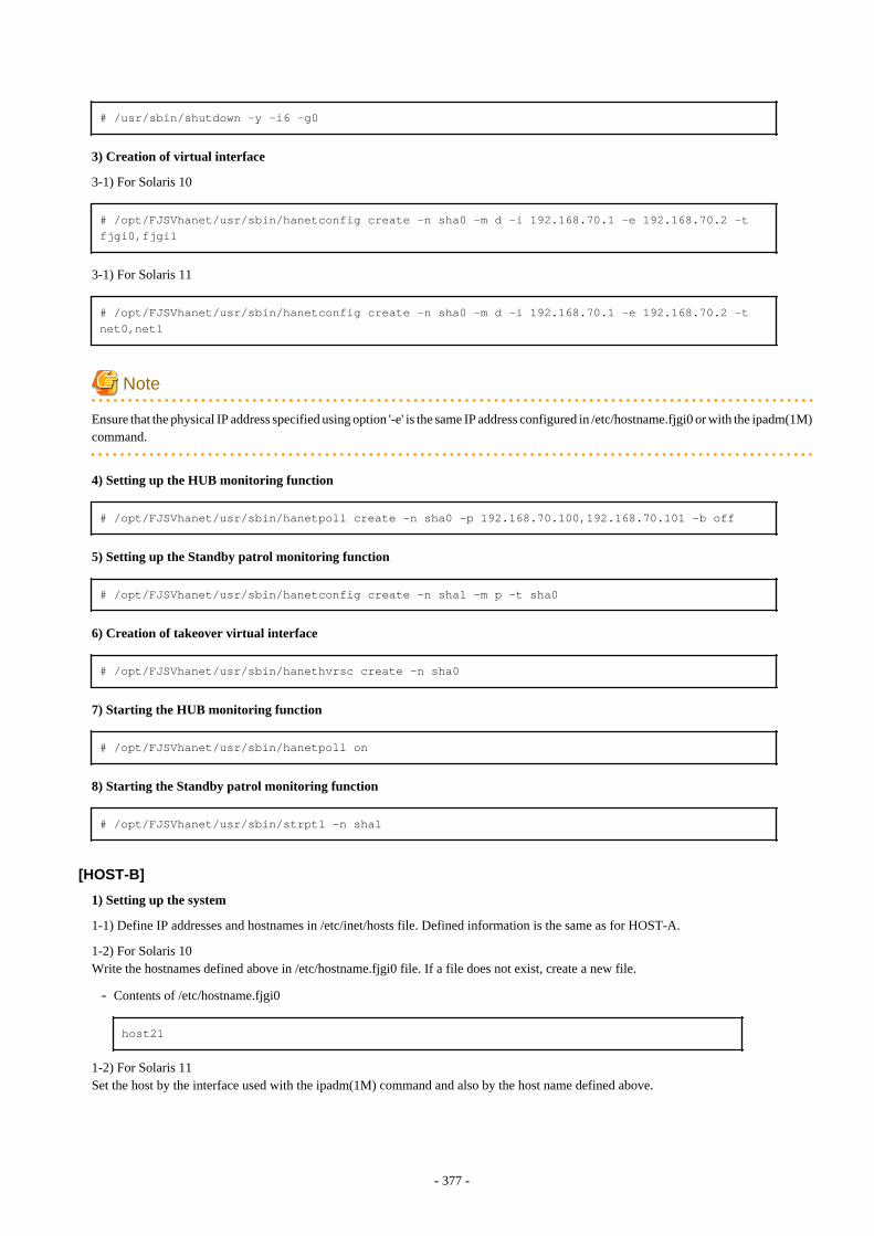
# /usr/sbin/shutdown -y -i6 -g0
3) Creation of virtual interface
3-1) For Solaris 10
# /opt/FJSVhanet/usr/sbin/hanetconfig create -n sha0 -m d -i 192.168.70.1 -e 192.168.70.2 -t fjgi0,fjgi1
3-1) For Solaris 11
# /opt/FJSVhanet/usr/sbin/hanetconfig create -n sha0 -m d -i 192.168.70.1 -e 192.168.70.2 -t net0,net1
Note
Ensure that the physical IP address specified using option '-e' is the same IP address configured in /etc/hostname.fjgi0 or with the ipadm(1M)command.
4) Setting up the HUB monitoring function
# /opt/FJSVhanet/usr/sbin/hanetpoll create -n sha0 -p 192.168.70.100,192.168.70.101 -b off
5) Setting up the Standby patrol monitoring function
# /opt/FJSVhanet/usr/sbin/hanetconfig create -n sha1 -m p -t sha0
6) Creation of takeover virtual interface
# /opt/FJSVhanet/usr/sbin/hanethvrsc create -n sha0
7) Starting the HUB monitoring function
# /opt/FJSVhanet/usr/sbin/hanetpoll on
8) Starting the Standby patrol monitoring function
# /opt/FJSVhanet/usr/sbin/strptl -n sha1
[HOST-B]
1) Setting up the system
1-1) Define IP addresses and hostnames in /etc/inet/hosts file. Defined information is the same as for HOST-A.
1-2) For Solaris 10Write the hostnames defined above in /etc/hostname.fjgi0 file. If a file does not exist, create a new file.
- Contents of /etc/hostname.fjgi0
host21
1-2) For Solaris 11Set the host by the interface used with the ipadm(1M) command and also by the host name defined above.
- 377 -
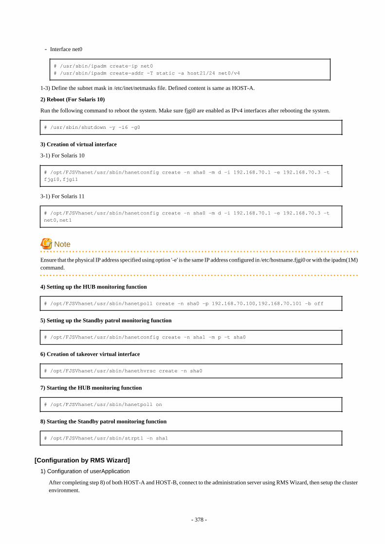
- Interface net0
# /usr/sbin/ipadm create-ip net0# /usr/sbin/ipadm create-addr -T static -a host21/24 net0/v4
1-3) Define the subnet mask in /etc/inet/netmasks file. Defined content is same as HOST-A.
2) Reboot (For Solaris 10)
Run the following command to reboot the system. Make sure fjgi0 are enabled as IPv4 interfaces after rebooting the system.
# /usr/sbin/shutdown -y -i6 -g0
3) Creation of virtual interface
3-1) For Solaris 10
# /opt/FJSVhanet/usr/sbin/hanetconfig create -n sha0 -m d -i 192.168.70.1 -e 192.168.70.3 -t fjgi0,fjgi1
3-1) For Solaris 11
# /opt/FJSVhanet/usr/sbin/hanetconfig create -n sha0 -m d -i 192.168.70.1 -e 192.168.70.3 -t net0,net1
Note
Ensure that the physical IP address specified using option '-e' is the same IP address configured in /etc/hostname.fjgi0 or with the ipadm(1M)command.
4) Setting up the HUB monitoring function
# /opt/FJSVhanet/usr/sbin/hanetpoll create -n sha0 -p 192.168.70.100,192.168.70.101 -b off
5) Setting up the Standby patrol monitoring function
# /opt/FJSVhanet/usr/sbin/hanetconfig create -n sha1 -m p -t sha0
6) Creation of takeover virtual interface
# /opt/FJSVhanet/usr/sbin/hanethvrsc create -n sha0
7) Starting the HUB monitoring function
# /opt/FJSVhanet/usr/sbin/hanetpoll on
8) Starting the Standby patrol monitoring function
# /opt/FJSVhanet/usr/sbin/strptl -n sha1
[Configuration by RMS Wizard]
1) Configuration of userApplication
After completing step 8) of both HOST-A and HOST-B, connect to the administration server using RMS Wizard, then setup the clusterenvironment.
- 378 -

To create Gls resource, select the SysNode for HOST-A and HOST-B. Once Gls is created, register it on the userApplication.When registering on the userApplication, select the SysNode compliant with HOST-A and HOST-B in the order of operation nodefollowed by standby node. Then, register the takeover address "192.168.70.1".
2) Starting of userApplication
After completing the configuration, start the userApplication to activate the takeover virtual interface on the operation node.
B.4.7 Example of the Cluster system (Mutual standby) without NIC sharingThis section describes an example configuration procedure of the network shown in the diagram below.
For configuring the cluster system, refer to the Cluster system manual.In this section, description of private LAN is omitted. The dotted line indicates that the interface is inactive.
If the Standby patrol monitoring function is not used, omit 5) and 8) in the procedure for setting up on each host.
[HOST-A]
1) Setting up the system
1-1) Define IP addresses and hostnames in /etc/inet/hosts file.
192.168.70.1 hosta # HOST-A/B Virtual IP (Takeover IP1)192.168.70.2 host11 # HOST-A Physical IP (1)192.168.70.3 host21 # HOST-B Physical IP (1)192.168.71.1 hostb # HOST-A/B Virtual IP (Takeover IP2)
- 379 -
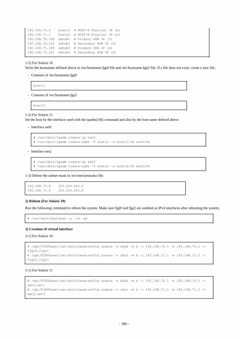
192.168.71.2 host12 # HOST-A Physical IP (2)192.168.71.3 host22 # HOST-B Physical IP (2)192.168.70.100 swhub1 # Primary HUB IP (1)192.168.70.101 swhub2 # Secondary HUB IP (1)192.168.71.100 swhub3 # Primary HUB IP (2)192.168.71.101 swhub4 # Secondary HUB IP (2)
1-2) For Solaris 10Write the hostnames defined above in /etc/hostname.fjgi0 file and /etc/hostname.fjgi2 file. If a file does not exist, create a new file.
- Contents of /etc/hostname.fjgi0
host11
- Contents of /etc/hostname.fjgi2
host12
1-2) For Solaris 11Set the host by the interface used with the ipadm(1M) command and also by the host name defined above.
- Interface net0
# /usr/sbin/ipadm create-ip net0# /usr/sbin/ipadm create-addr -T static -a host11/24 net0/v4
- Interface net2
# /usr/sbin/ipadm create-ip net2# /usr/sbin/ipadm create-addr -T static -a host12/24 net2/v4
1-3) Define the subnet mask in /etc/inet/netmasks file.
192.168.70.0 255.255.255.0192.168.71.0 255.255.255.0
2) Reboot (For Solaris 10)
Run the following command to reboot the system. Make sure fjgi0 and fjgi2 are enabled as IPv4 interfaces after rebooting the system.
# /usr/sbin/shutdown -y -i6 -g0
3) Creation of virtual interface
3-1) For Solaris 10
# /opt/FJSVhanet/usr/sbin/hanetconfig create -n sha0 -m d -i 192.168.70.1 -e 192.168.70.2 -t fjgi0,fjgi1# /opt/FJSVhanet/usr/sbin/hanetconfig create -n sha1 -m d -i 192.168.71.1 -e 192.168.71.2 -t fjgi2,fjgi3
3-1) For Solaris 11
# /opt/FJSVhanet/usr/sbin/hanetconfig create -n sha0 -m d -i 192.168.70.1 -e 192.168.70.2 -t net0,net1# /opt/FJSVhanet/usr/sbin/hanetconfig create -n sha1 -m d -i 192.168.71.1 -e 192.168.71.2 -t net2,net3
- 380 -
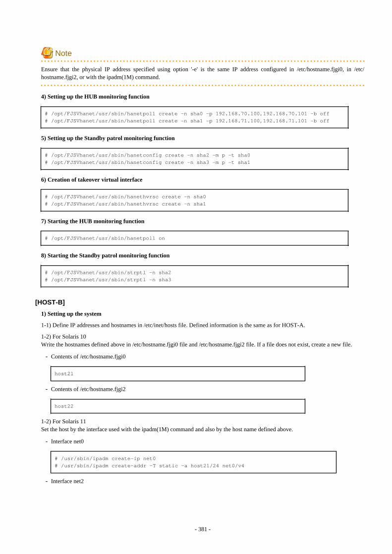
Note
Ensure that the physical IP address specified using option '-e' is the same IP address configured in /etc/hostname.fjgi0, in /etc/hostname.fjgi2, or with the ipadm(1M) command.
4) Setting up the HUB monitoring function
# /opt/FJSVhanet/usr/sbin/hanetpoll create -n sha0 -p 192.168.70.100,192.168.70.101 -b off# /opt/FJSVhanet/usr/sbin/hanetpoll create -n sha1 -p 192.168.71.100,192.168.71.101 -b off
5) Setting up the Standby patrol monitoring function
# /opt/FJSVhanet/usr/sbin/hanetconfig create -n sha2 -m p -t sha0# /opt/FJSVhanet/usr/sbin/hanetconfig create -n sha3 -m p -t sha1
6) Creation of takeover virtual interface
# /opt/FJSVhanet/usr/sbin/hanethvrsc create -n sha0# /opt/FJSVhanet/usr/sbin/hanethvrsc create -n sha1
7) Starting the HUB monitoring function
# /opt/FJSVhanet/usr/sbin/hanetpoll on
8) Starting the Standby patrol monitoring function
# /opt/FJSVhanet/usr/sbin/strptl -n sha2# /opt/FJSVhanet/usr/sbin/strptl -n sha3
[HOST-B]
1) Setting up the system
1-1) Define IP addresses and hostnames in /etc/inet/hosts file. Defined information is the same as for HOST-A.
1-2) For Solaris 10Write the hostnames defined above in /etc/hostname.fjgi0 file and /etc/hostname.fjgi2 file. If a file does not exist, create a new file.
- Contents of /etc/hostname.fjgi0
host21
- Contents of /etc/hostname.fjgi2
host22
1-2) For Solaris 11Set the host by the interface used with the ipadm(1M) command and also by the host name defined above.
- Interface net0
# /usr/sbin/ipadm create-ip net0# /usr/sbin/ipadm create-addr -T static -a host21/24 net0/v4
- Interface net2
- 381 -
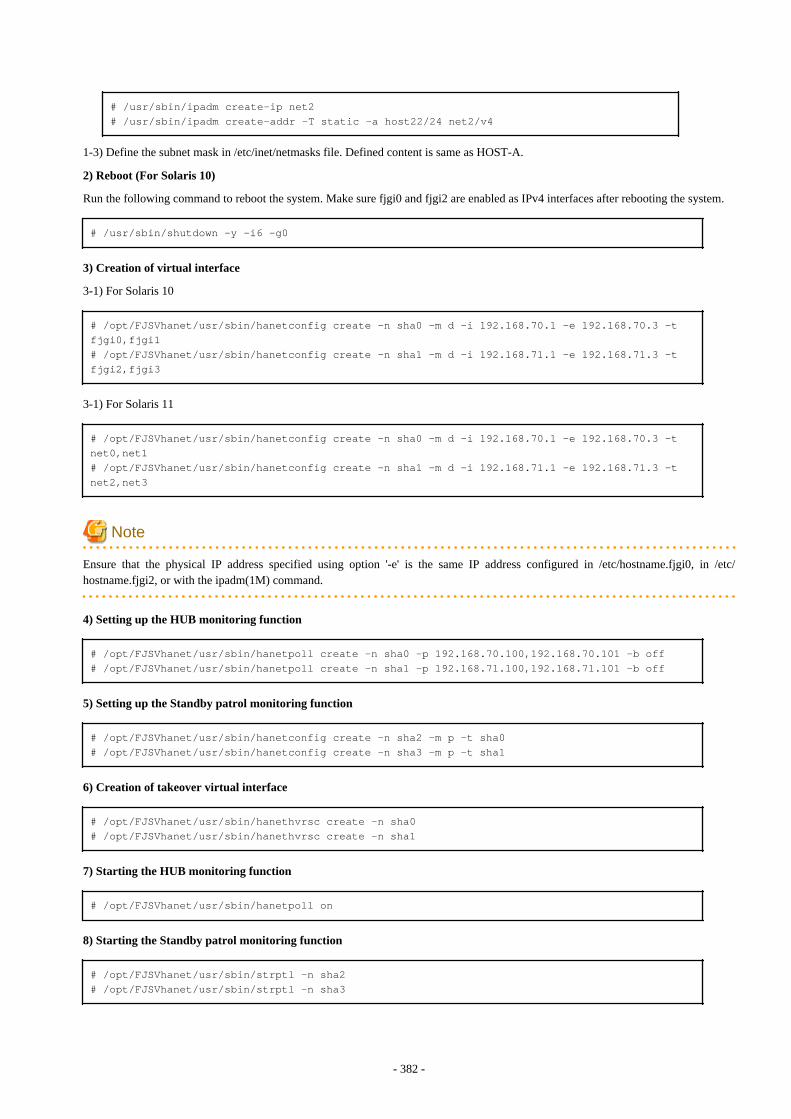
# /usr/sbin/ipadm create-ip net2# /usr/sbin/ipadm create-addr -T static -a host22/24 net2/v4
1-3) Define the subnet mask in /etc/inet/netmasks file. Defined content is same as HOST-A.
2) Reboot (For Solaris 10)
Run the following command to reboot the system. Make sure fjgi0 and fjgi2 are enabled as IPv4 interfaces after rebooting the system.
# /usr/sbin/shutdown -y -i6 -g0
3) Creation of virtual interface
3-1) For Solaris 10
# /opt/FJSVhanet/usr/sbin/hanetconfig create -n sha0 -m d -i 192.168.70.1 -e 192.168.70.3 -t fjgi0,fjgi1# /opt/FJSVhanet/usr/sbin/hanetconfig create -n sha1 -m d -i 192.168.71.1 -e 192.168.71.3 -t fjgi2,fjgi3
3-1) For Solaris 11
# /opt/FJSVhanet/usr/sbin/hanetconfig create -n sha0 -m d -i 192.168.70.1 -e 192.168.70.3 -t net0,net1# /opt/FJSVhanet/usr/sbin/hanetconfig create -n sha1 -m d -i 192.168.71.1 -e 192.168.71.3 -t net2,net3
Note
Ensure that the physical IP address specified using option '-e' is the same IP address configured in /etc/hostname.fjgi0, in /etc/hostname.fjgi2, or with the ipadm(1M) command.
4) Setting up the HUB monitoring function
# /opt/FJSVhanet/usr/sbin/hanetpoll create -n sha0 -p 192.168.70.100,192.168.70.101 -b off# /opt/FJSVhanet/usr/sbin/hanetpoll create -n sha1 -p 192.168.71.100,192.168.71.101 -b off
5) Setting up the Standby patrol monitoring function
# /opt/FJSVhanet/usr/sbin/hanetconfig create -n sha2 -m p -t sha0# /opt/FJSVhanet/usr/sbin/hanetconfig create -n sha3 -m p -t sha1
6) Creation of takeover virtual interface
# /opt/FJSVhanet/usr/sbin/hanethvrsc create -n sha0# /opt/FJSVhanet/usr/sbin/hanethvrsc create -n sha1
7) Starting the HUB monitoring function
# /opt/FJSVhanet/usr/sbin/hanetpoll on
8) Starting the Standby patrol monitoring function
# /opt/FJSVhanet/usr/sbin/strptl -n sha2# /opt/FJSVhanet/usr/sbin/strptl -n sha3
- 382 -
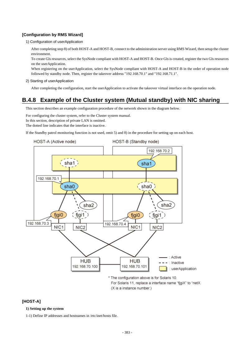
[Configuration by RMS Wizard]
1) Configuration of userApplication
After completing step 8) of both HOST-A and HOST-B, connect to the administration server using RMS Wizard, then setup the clusterenvironment.To create Gls resources, select the SysNode compliant with HOST-A and HOST-B. Once Gls is created, register the two Gls resourceson the userApplication.When registering on the userApplication, select the SysNode compliant with HOST-A and HOST-B in the order of operation nodefollowed by standby node. Then, register the takeover address "192.168.70.1" and "192.168.71.1".
2) Starting of userApplication
After completing the configuration, start the userApplication to activate the takeover virtual interface on the operation node.
B.4.8 Example of the Cluster system (Mutual standby) with NIC sharingThis section describes an example configuration procedure of the network shown in the diagram below.
For configuring the cluster system, refer to the Cluster system manual.In this section, description of private LAN is omitted. The dotted line indicates that the interface is inactive.
If the Standby patrol monitoring function is not used, omit 5) and 8) in the procedure for setting up on each host.
[HOST-A]
1) Setting up the system
1-1) Define IP addresses and hostnames in /etc/inet/hosts file.
- 383 -
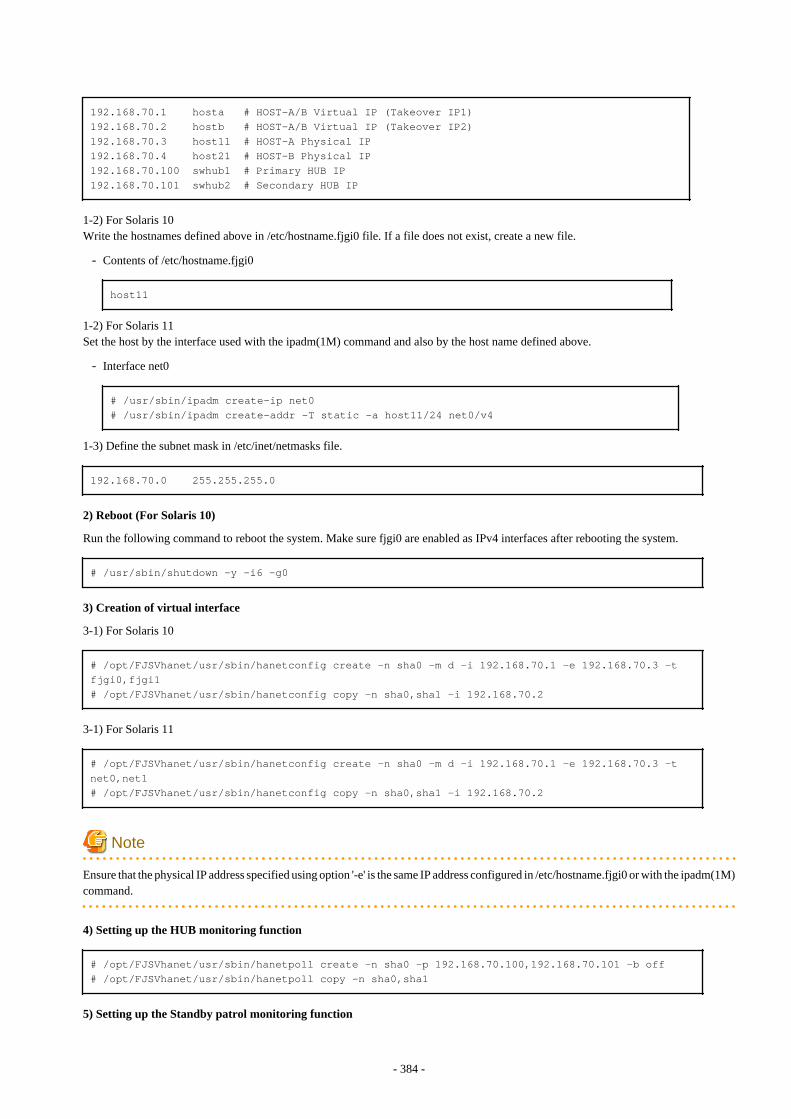
192.168.70.1 hosta # HOST-A/B Virtual IP (Takeover IP1)192.168.70.2 hostb # HOST-A/B Virtual IP (Takeover IP2)192.168.70.3 host11 # HOST-A Physical IP192.168.70.4 host21 # HOST-B Physical IP192.168.70.100 swhub1 # Primary HUB IP192.168.70.101 swhub2 # Secondary HUB IP
1-2) For Solaris 10Write the hostnames defined above in /etc/hostname.fjgi0 file. If a file does not exist, create a new file.
- Contents of /etc/hostname.fjgi0
host11
1-2) For Solaris 11Set the host by the interface used with the ipadm(1M) command and also by the host name defined above.
- Interface net0
# /usr/sbin/ipadm create-ip net0# /usr/sbin/ipadm create-addr -T static -a host11/24 net0/v4
1-3) Define the subnet mask in /etc/inet/netmasks file.
192.168.70.0 255.255.255.0
2) Reboot (For Solaris 10)
Run the following command to reboot the system. Make sure fjgi0 are enabled as IPv4 interfaces after rebooting the system.
# /usr/sbin/shutdown -y -i6 -g0
3) Creation of virtual interface
3-1) For Solaris 10
# /opt/FJSVhanet/usr/sbin/hanetconfig create -n sha0 -m d -i 192.168.70.1 -e 192.168.70.3 -t fjgi0,fjgi1# /opt/FJSVhanet/usr/sbin/hanetconfig copy -n sha0,sha1 -i 192.168.70.2
3-1) For Solaris 11
# /opt/FJSVhanet/usr/sbin/hanetconfig create -n sha0 -m d -i 192.168.70.1 -e 192.168.70.3 -t net0,net1# /opt/FJSVhanet/usr/sbin/hanetconfig copy -n sha0,sha1 -i 192.168.70.2
Note
Ensure that the physical IP address specified using option '-e' is the same IP address configured in /etc/hostname.fjgi0 or with the ipadm(1M)command.
4) Setting up the HUB monitoring function
# /opt/FJSVhanet/usr/sbin/hanetpoll create -n sha0 -p 192.168.70.100,192.168.70.101 -b off# /opt/FJSVhanet/usr/sbin/hanetpoll copy -n sha0,sha1
5) Setting up the Standby patrol monitoring function
- 384 -
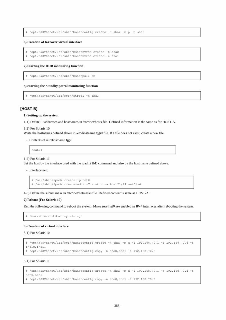
# /opt/FJSVhanet/usr/sbin/hanetconfig create -n sha2 -m p -t sha0
6) Creation of takeover virtual interface
# /opt/FJSVhanet/usr/sbin/hanethvrsc create -n sha0# /opt/FJSVhanet/usr/sbin/hanethvrsc create -n sha1
7) Starting the HUB monitoring function
# /opt/FJSVhanet/usr/sbin/hanetpoll on
8) Starting the Standby patrol monitoring function
# /opt/FJSVhanet/usr/sbin/strptl -n sha2
[HOST-B]
1) Setting up the system
1-1) Define IP addresses and hostnames in /etc/inet/hosts file. Defined information is the same as for HOST-A.
1-2) For Solaris 10Write the hostnames defined above in /etc/hostname.fjgi0 file. If a file does not exist, create a new file.
- Contents of /etc/hostname.fjgi0
host21
1-2) For Solaris 11Set the host by the interface used with the ipadm(1M) command and also by the host name defined above.
- Interface net0
# /usr/sbin/ipadm create-ip net0# /usr/sbin/ipadm create-addr -T static -a host21/24 net0/v4
1-3) Define the subnet mask in /etc/inet/netmasks file. Defined content is same as HOST-A.
2) Reboot (For Solaris 10)
Run the following command to reboot the system. Make sure fjgi0 are enabled as IPv4 interfaces after rebooting the system.
# /usr/sbin/shutdown -y -i6 -g0
3) Creation of virtual interface
3-1) For Solaris 10
# /opt/FJSVhanet/usr/sbin/hanetconfig create -n sha0 -m d -i 192.168.70.1 -e 192.168.70.4 -t fjgi0,fjgi1# /opt/FJSVhanet/usr/sbin/hanetconfig copy -n sha0,sha1 -i 192.168.70.2
3-1) For Solaris 11
# /opt/FJSVhanet/usr/sbin/hanetconfig create -n sha0 -m d -i 192.168.70.1 -e 192.168.70.4 -t net0,net1# /opt/FJSVhanet/usr/sbin/hanetconfig copy -n sha0,sha1 -i 192.168.70.2
- 385 -
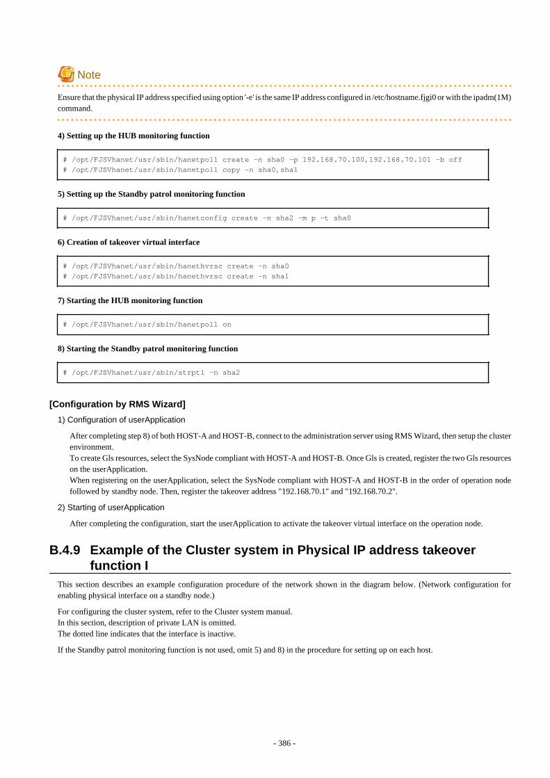
Note
Ensure that the physical IP address specified using option '-e' is the same IP address configured in /etc/hostname.fjgi0 or with the ipadm(1M)command.
4) Setting up the HUB monitoring function
# /opt/FJSVhanet/usr/sbin/hanetpoll create -n sha0 -p 192.168.70.100,192.168.70.101 -b off# /opt/FJSVhanet/usr/sbin/hanetpoll copy -n sha0,sha1
5) Setting up the Standby patrol monitoring function
# /opt/FJSVhanet/usr/sbin/hanetconfig create -n sha2 -m p -t sha0
6) Creation of takeover virtual interface
# /opt/FJSVhanet/usr/sbin/hanethvrsc create -n sha0# /opt/FJSVhanet/usr/sbin/hanethvrsc create -n sha1
7) Starting the HUB monitoring function
# /opt/FJSVhanet/usr/sbin/hanetpoll on
8) Starting the Standby patrol monitoring function
# /opt/FJSVhanet/usr/sbin/strptl -n sha2
[Configuration by RMS Wizard]
1) Configuration of userApplication
After completing step 8) of both HOST-A and HOST-B, connect to the administration server using RMS Wizard, then setup the clusterenvironment.To create Gls resources, select the SysNode compliant with HOST-A and HOST-B. Once Gls is created, register the two Gls resourceson the userApplication.When registering on the userApplication, select the SysNode compliant with HOST-A and HOST-B in the order of operation nodefollowed by standby node. Then, register the takeover address "192.168.70.1" and "192.168.70.2".
2) Starting of userApplication
After completing the configuration, start the userApplication to activate the takeover virtual interface on the operation node.
B.4.9 Example of the Cluster system in Physical IP address takeoverfunction I
This section describes an example configuration procedure of the network shown in the diagram below. (Network configuration forenabling physical interface on a standby node.)
For configuring the cluster system, refer to the Cluster system manual.In this section, description of private LAN is omitted. The dotted line indicates that the interface is inactive.
If the Standby patrol monitoring function is not used, omit 5) and 8) in the procedure for setting up on each host.
- 386 -
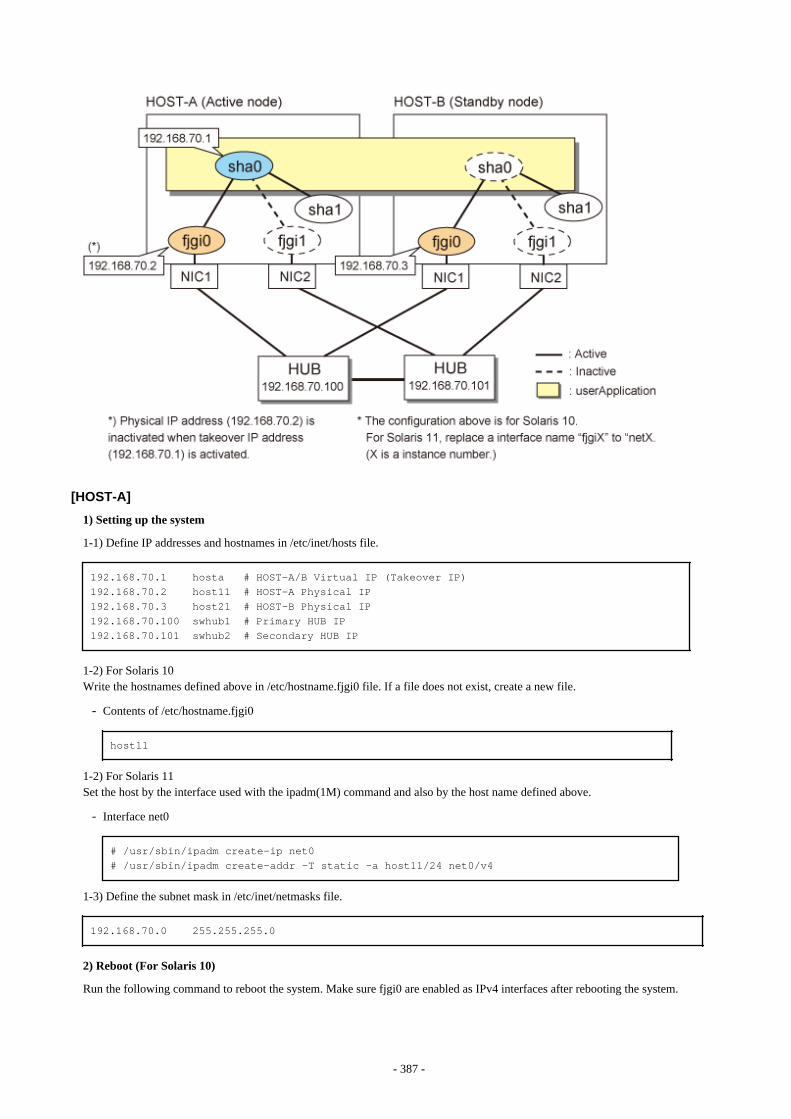
[HOST-A]
1) Setting up the system
1-1) Define IP addresses and hostnames in /etc/inet/hosts file.
192.168.70.1 hosta # HOST-A/B Virtual IP (Takeover IP)192.168.70.2 host11 # HOST-A Physical IP192.168.70.3 host21 # HOST-B Physical IP192.168.70.100 swhub1 # Primary HUB IP192.168.70.101 swhub2 # Secondary HUB IP
1-2) For Solaris 10Write the hostnames defined above in /etc/hostname.fjgi0 file. If a file does not exist, create a new file.
- Contents of /etc/hostname.fjgi0
host11
1-2) For Solaris 11Set the host by the interface used with the ipadm(1M) command and also by the host name defined above.
- Interface net0
# /usr/sbin/ipadm create-ip net0# /usr/sbin/ipadm create-addr -T static -a host11/24 net0/v4
1-3) Define the subnet mask in /etc/inet/netmasks file.
192.168.70.0 255.255.255.0
2) Reboot (For Solaris 10)
Run the following command to reboot the system. Make sure fjgi0 are enabled as IPv4 interfaces after rebooting the system.
- 387 -
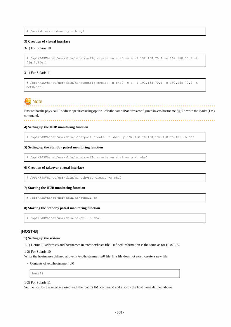
# /usr/sbin/shutdown -y -i6 -g0
3) Creation of virtual interface
3-1) For Solaris 10
# /opt/FJSVhanet/usr/sbin/hanetconfig create -n sha0 -m e -i 192.168.70.1 -e 192.168.70.2 -t fjgi0,fjgi1
3-1) For Solaris 11
# /opt/FJSVhanet/usr/sbin/hanetconfig create -n sha0 -m e -i 192.168.70.1 -e 192.168.70.2 -t net0,net1
Note
Ensure that the physical IP address specified using option '-e' is the same IP address configured in /etc/hostname.fjgi0 or with the ipadm(1M)command.
4) Setting up the HUB monitoring function
# /opt/FJSVhanet/usr/sbin/hanetpoll create -n sha0 -p 192.168.70.100,192.168.70.101 -b off
5) Setting up the Standby patrol monitoring function
# /opt/FJSVhanet/usr/sbin/hanetconfig create -n sha1 -m p -t sha0
6) Creation of takeover virtual interface
# /opt/FJSVhanet/usr/sbin/hanethvrsc create -n sha0
7) Starting the HUB monitoring function
# /opt/FJSVhanet/usr/sbin/hanetpoll on
8) Starting the Standby patrol monitoring function
# /opt/FJSVhanet/usr/sbin/strptl -n sha1
[HOST-B]
1) Setting up the system
1-1) Define IP addresses and hostnames in /etc/inet/hosts file. Defined information is the same as for HOST-A.
1-2) For Solaris 10Write the hostnames defined above in /etc/hostname.fjgi0 file. If a file does not exist, create a new file.
- Contents of /etc/hostname.fjgi0
host21
1-2) For Solaris 11Set the host by the interface used with the ipadm(1M) command and also by the host name defined above.
- 388 -
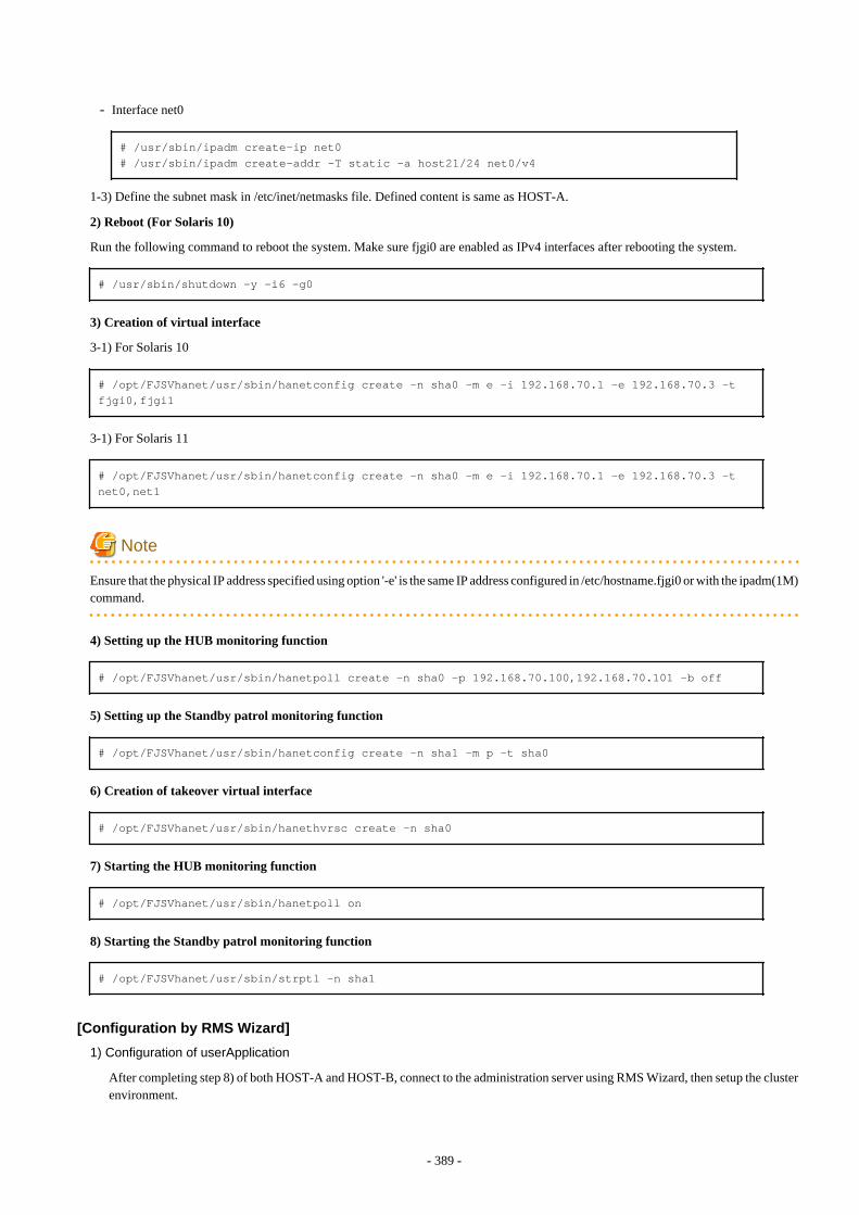
- Interface net0
# /usr/sbin/ipadm create-ip net0# /usr/sbin/ipadm create-addr -T static -a host21/24 net0/v4
1-3) Define the subnet mask in /etc/inet/netmasks file. Defined content is same as HOST-A.
2) Reboot (For Solaris 10)
Run the following command to reboot the system. Make sure fjgi0 are enabled as IPv4 interfaces after rebooting the system.
# /usr/sbin/shutdown -y -i6 -g0
3) Creation of virtual interface
3-1) For Solaris 10
# /opt/FJSVhanet/usr/sbin/hanetconfig create -n sha0 -m e -i 192.168.70.1 -e 192.168.70.3 -t fjgi0,fjgi1
3-1) For Solaris 11
# /opt/FJSVhanet/usr/sbin/hanetconfig create -n sha0 -m e -i 192.168.70.1 -e 192.168.70.3 -t net0,net1
Note
Ensure that the physical IP address specified using option '-e' is the same IP address configured in /etc/hostname.fjgi0 or with the ipadm(1M)command.
4) Setting up the HUB monitoring function
# /opt/FJSVhanet/usr/sbin/hanetpoll create -n sha0 -p 192.168.70.100,192.168.70.101 -b off
5) Setting up the Standby patrol monitoring function
# /opt/FJSVhanet/usr/sbin/hanetconfig create -n sha1 -m p -t sha0
6) Creation of takeover virtual interface
# /opt/FJSVhanet/usr/sbin/hanethvrsc create -n sha0
7) Starting the HUB monitoring function
# /opt/FJSVhanet/usr/sbin/hanetpoll on
8) Starting the Standby patrol monitoring function
# /opt/FJSVhanet/usr/sbin/strptl -n sha1
[Configuration by RMS Wizard]
1) Configuration of userApplication
After completing step 8) of both HOST-A and HOST-B, connect to the administration server using RMS Wizard, then setup the clusterenvironment.
- 389 -
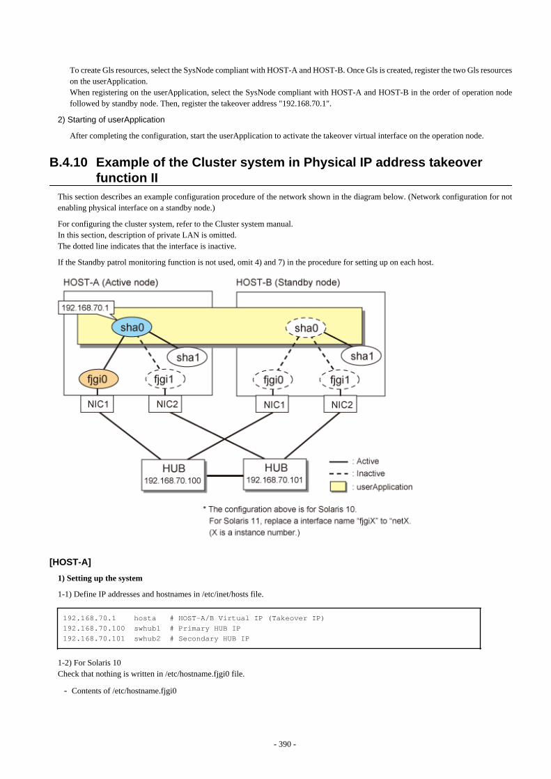
To create Gls resources, select the SysNode compliant with HOST-A and HOST-B. Once Gls is created, register the two Gls resourceson the userApplication.When registering on the userApplication, select the SysNode compliant with HOST-A and HOST-B in the order of operation nodefollowed by standby node. Then, register the takeover address "192.168.70.1".
2) Starting of userApplication
After completing the configuration, start the userApplication to activate the takeover virtual interface on the operation node.
B.4.10 Example of the Cluster system in Physical IP address takeoverfunction II
This section describes an example configuration procedure of the network shown in the diagram below. (Network configuration for notenabling physical interface on a standby node.)
For configuring the cluster system, refer to the Cluster system manual.In this section, description of private LAN is omitted. The dotted line indicates that the interface is inactive.
If the Standby patrol monitoring function is not used, omit 4) and 7) in the procedure for setting up on each host.
[HOST-A]
1) Setting up the system
1-1) Define IP addresses and hostnames in /etc/inet/hosts file.
192.168.70.1 hosta # HOST-A/B Virtual IP (Takeover IP)192.168.70.100 swhub1 # Primary HUB IP192.168.70.101 swhub2 # Secondary HUB IP
1-2) For Solaris 10Check that nothing is written in /etc/hostname.fjgi0 file.
- Contents of /etc/hostname.fjgi0
- 390 -
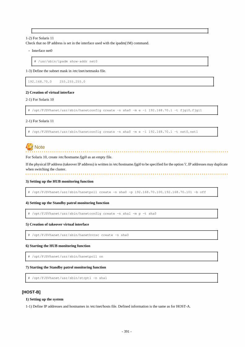
1-2) For Solaris 11Check that no IP address is set in the interface used with the ipadm(1M) command.
- Interface net0
# /usr/sbin/ipadm show-addr net0
1-3) Define the subnet mask in /etc/inet/netmasks file.
192.168.70.0 255.255.255.0
2) Creation of virtual interface
2-1) For Solaris 10
# /opt/FJSVhanet/usr/sbin/hanetconfig create -n sha0 -m e -i 192.168.70.1 -t fjgi0,fjgi1
2-1) For Solaris 11
# /opt/FJSVhanet/usr/sbin/hanetconfig create -n sha0 -m e -i 192.168.70.1 -t net0,net1
Note
For Solaris 10, create /etc/hostname.fjgi0 as an empty file.
If the physical IP address (takeover IP address) is written in /etc/hostname.fjgi0 to be specified for the option 'i', IP addresses may duplicatewhen switching the cluster.
3) Setting up the HUB monitoring function
# /opt/FJSVhanet/usr/sbin/hanetpoll create -n sha0 -p 192.168.70.100,192.168.70.101 -b off
4) Setting up the Standby patrol monitoring function
# /opt/FJSVhanet/usr/sbin/hanetconfig create -n sha1 -m p -t sha0
5) Creation of takeover virtual interface
# /opt/FJSVhanet/usr/sbin/hanethvrsc create -n sha0
6) Starting the HUB monitoring function
# /opt/FJSVhanet/usr/sbin/hanetpoll on
7) Starting the Standby patrol monitoring function
# /opt/FJSVhanet/usr/sbin/strptl -n sha1
[HOST-B]
1) Setting up the system
1-1) Define IP addresses and hostnames in /etc/inet/hosts file. Defined information is the same as for HOST-A.
- 391 -
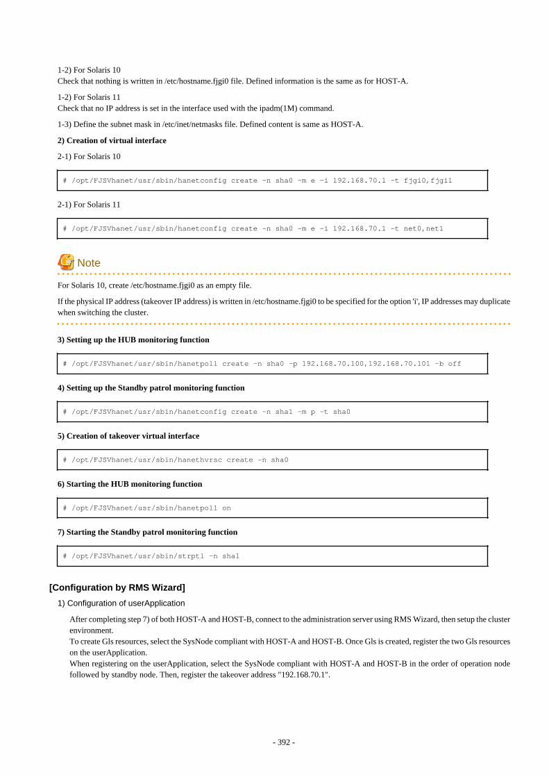
1-2) For Solaris 10Check that nothing is written in /etc/hostname.fjgi0 file. Defined information is the same as for HOST-A.
1-2) For Solaris 11Check that no IP address is set in the interface used with the ipadm(1M) command.
1-3) Define the subnet mask in /etc/inet/netmasks file. Defined content is same as HOST-A.
2) Creation of virtual interface
2-1) For Solaris 10
# /opt/FJSVhanet/usr/sbin/hanetconfig create -n sha0 -m e -i 192.168.70.1 -t fjgi0,fjgi1
2-1) For Solaris 11
# /opt/FJSVhanet/usr/sbin/hanetconfig create -n sha0 -m e -i 192.168.70.1 -t net0,net1
Note
For Solaris 10, create /etc/hostname.fjgi0 as an empty file.
If the physical IP address (takeover IP address) is written in /etc/hostname.fjgi0 to be specified for the option 'i', IP addresses may duplicatewhen switching the cluster.
3) Setting up the HUB monitoring function
# /opt/FJSVhanet/usr/sbin/hanetpoll create -n sha0 -p 192.168.70.100,192.168.70.101 -b off
4) Setting up the Standby patrol monitoring function
# /opt/FJSVhanet/usr/sbin/hanetconfig create -n sha1 -m p -t sha0
5) Creation of takeover virtual interface
# /opt/FJSVhanet/usr/sbin/hanethvrsc create -n sha0
6) Starting the HUB monitoring function
# /opt/FJSVhanet/usr/sbin/hanetpoll on
7) Starting the Standby patrol monitoring function
# /opt/FJSVhanet/usr/sbin/strptl -n sha1
[Configuration by RMS Wizard]
1) Configuration of userApplication
After completing step 7) of both HOST-A and HOST-B, connect to the administration server using RMS Wizard, then setup the clusterenvironment.To create Gls resources, select the SysNode compliant with HOST-A and HOST-B. Once Gls is created, register the two Gls resourceson the userApplication.When registering on the userApplication, select the SysNode compliant with HOST-A and HOST-B in the order of operation nodefollowed by standby node. Then, register the takeover address "192.168.70.1".
- 392 -
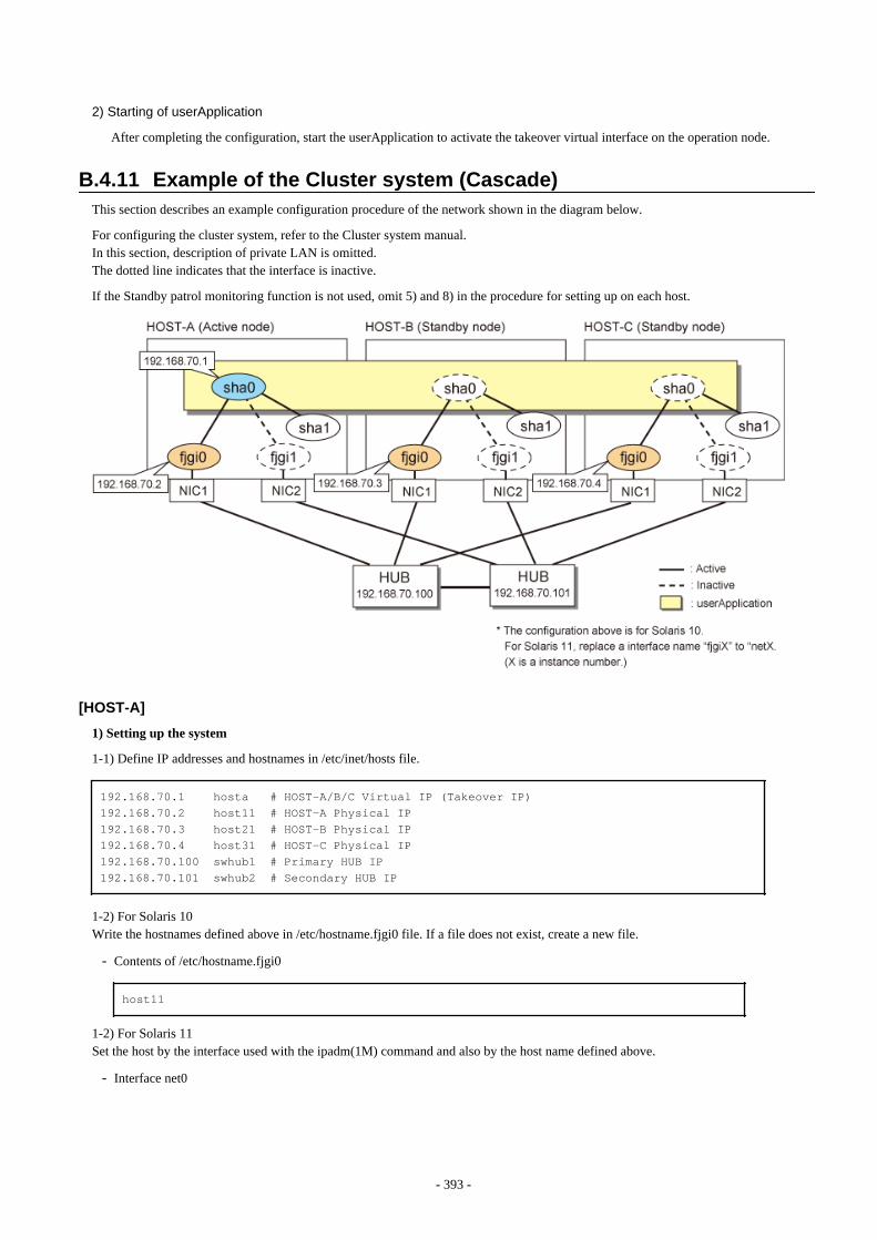
2) Starting of userApplication
After completing the configuration, start the userApplication to activate the takeover virtual interface on the operation node.
B.4.11 Example of the Cluster system (Cascade)This section describes an example configuration procedure of the network shown in the diagram below.
For configuring the cluster system, refer to the Cluster system manual.In this section, description of private LAN is omitted. The dotted line indicates that the interface is inactive.
If the Standby patrol monitoring function is not used, omit 5) and 8) in the procedure for setting up on each host.
[HOST-A]
1) Setting up the system
1-1) Define IP addresses and hostnames in /etc/inet/hosts file.
192.168.70.1 hosta # HOST-A/B/C Virtual IP (Takeover IP)192.168.70.2 host11 # HOST-A Physical IP192.168.70.3 host21 # HOST-B Physical IP192.168.70.4 host31 # HOST-C Physical IP192.168.70.100 swhub1 # Primary HUB IP192.168.70.101 swhub2 # Secondary HUB IP
1-2) For Solaris 10Write the hostnames defined above in /etc/hostname.fjgi0 file. If a file does not exist, create a new file.
- Contents of /etc/hostname.fjgi0
host11
1-2) For Solaris 11Set the host by the interface used with the ipadm(1M) command and also by the host name defined above.
- Interface net0
- 393 -
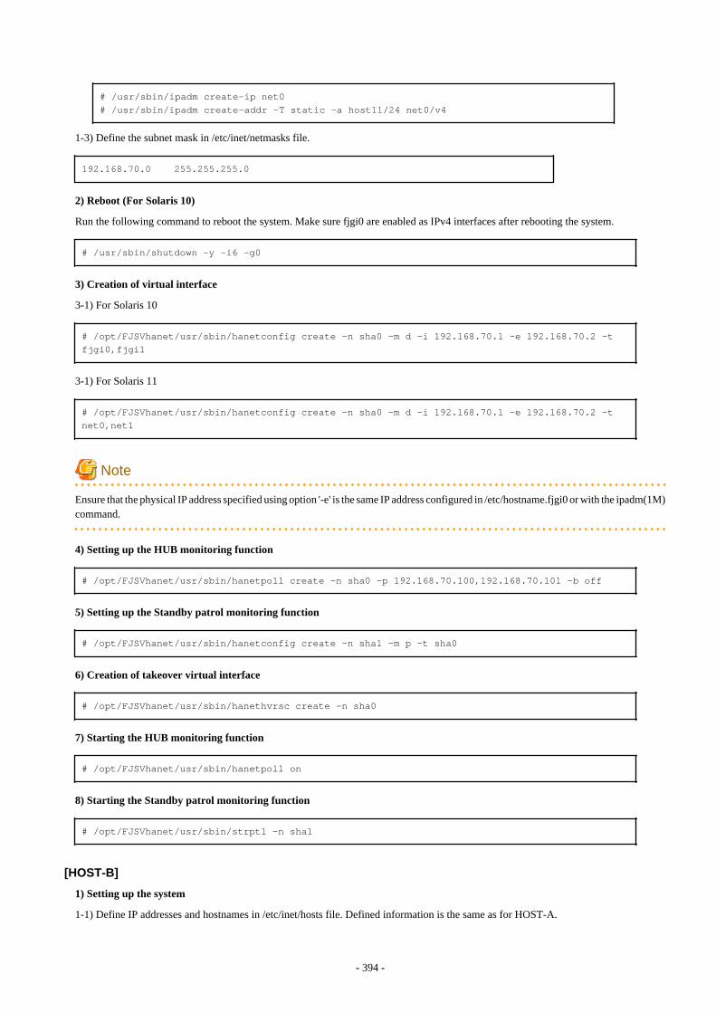
# /usr/sbin/ipadm create-ip net0# /usr/sbin/ipadm create-addr -T static -a host11/24 net0/v4
1-3) Define the subnet mask in /etc/inet/netmasks file.
192.168.70.0 255.255.255.0
2) Reboot (For Solaris 10)
Run the following command to reboot the system. Make sure fjgi0 are enabled as IPv4 interfaces after rebooting the system.
# /usr/sbin/shutdown -y -i6 -g0
3) Creation of virtual interface
3-1) For Solaris 10
# /opt/FJSVhanet/usr/sbin/hanetconfig create -n sha0 -m d -i 192.168.70.1 -e 192.168.70.2 -t fjgi0,fjgi1
3-1) For Solaris 11
# /opt/FJSVhanet/usr/sbin/hanetconfig create -n sha0 -m d -i 192.168.70.1 -e 192.168.70.2 -t net0,net1
Note
Ensure that the physical IP address specified using option '-e' is the same IP address configured in /etc/hostname.fjgi0 or with the ipadm(1M)command.
4) Setting up the HUB monitoring function
# /opt/FJSVhanet/usr/sbin/hanetpoll create -n sha0 -p 192.168.70.100,192.168.70.101 -b off
5) Setting up the Standby patrol monitoring function
# /opt/FJSVhanet/usr/sbin/hanetconfig create -n sha1 -m p -t sha0
6) Creation of takeover virtual interface
# /opt/FJSVhanet/usr/sbin/hanethvrsc create -n sha0
7) Starting the HUB monitoring function
# /opt/FJSVhanet/usr/sbin/hanetpoll on
8) Starting the Standby patrol monitoring function
# /opt/FJSVhanet/usr/sbin/strptl -n sha1
[HOST-B]
1) Setting up the system
1-1) Define IP addresses and hostnames in /etc/inet/hosts file. Defined information is the same as for HOST-A.
- 394 -
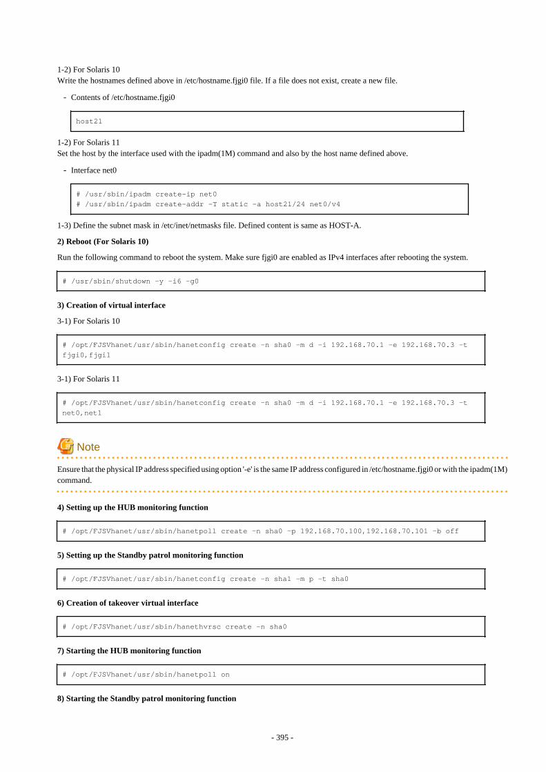
1-2) For Solaris 10Write the hostnames defined above in /etc/hostname.fjgi0 file. If a file does not exist, create a new file.
- Contents of /etc/hostname.fjgi0
host21
1-2) For Solaris 11Set the host by the interface used with the ipadm(1M) command and also by the host name defined above.
- Interface net0
# /usr/sbin/ipadm create-ip net0# /usr/sbin/ipadm create-addr -T static -a host21/24 net0/v4
1-3) Define the subnet mask in /etc/inet/netmasks file. Defined content is same as HOST-A.
2) Reboot (For Solaris 10)
Run the following command to reboot the system. Make sure fjgi0 are enabled as IPv4 interfaces after rebooting the system.
# /usr/sbin/shutdown -y -i6 -g0
3) Creation of virtual interface
3-1) For Solaris 10
# /opt/FJSVhanet/usr/sbin/hanetconfig create -n sha0 -m d -i 192.168.70.1 -e 192.168.70.3 -t fjgi0,fjgi1
3-1) For Solaris 11
# /opt/FJSVhanet/usr/sbin/hanetconfig create -n sha0 -m d -i 192.168.70.1 -e 192.168.70.3 -t net0,net1
Note
Ensure that the physical IP address specified using option '-e' is the same IP address configured in /etc/hostname.fjgi0 or with the ipadm(1M)command.
4) Setting up the HUB monitoring function
# /opt/FJSVhanet/usr/sbin/hanetpoll create -n sha0 -p 192.168.70.100,192.168.70.101 -b off
5) Setting up the Standby patrol monitoring function
# /opt/FJSVhanet/usr/sbin/hanetconfig create -n sha1 -m p -t sha0
6) Creation of takeover virtual interface
# /opt/FJSVhanet/usr/sbin/hanethvrsc create -n sha0
7) Starting the HUB monitoring function
# /opt/FJSVhanet/usr/sbin/hanetpoll on
8) Starting the Standby patrol monitoring function
- 395 -
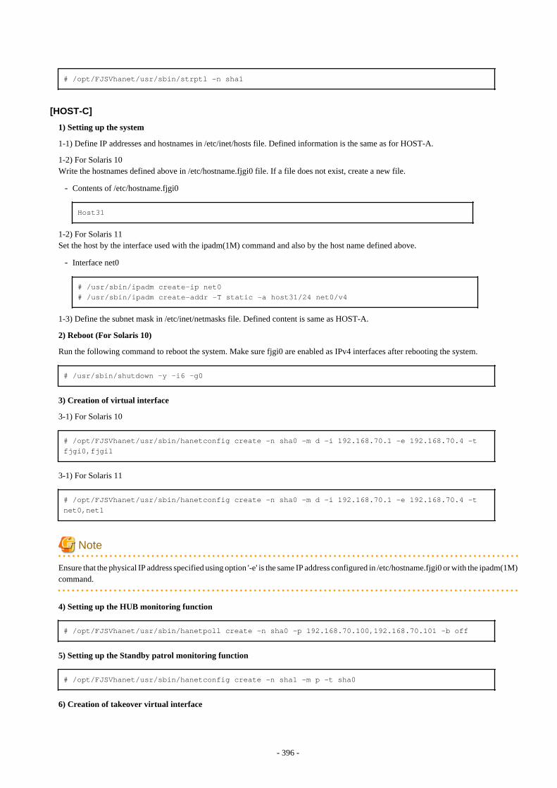
# /opt/FJSVhanet/usr/sbin/strptl -n sha1
[HOST-C]
1) Setting up the system
1-1) Define IP addresses and hostnames in /etc/inet/hosts file. Defined information is the same as for HOST-A.
1-2) For Solaris 10Write the hostnames defined above in /etc/hostname.fjgi0 file. If a file does not exist, create a new file.
- Contents of /etc/hostname.fjgi0
Host31
1-2) For Solaris 11Set the host by the interface used with the ipadm(1M) command and also by the host name defined above.
- Interface net0
# /usr/sbin/ipadm create-ip net0# /usr/sbin/ipadm create-addr -T static -a host31/24 net0/v4
1-3) Define the subnet mask in /etc/inet/netmasks file. Defined content is same as HOST-A.
2) Reboot (For Solaris 10)
Run the following command to reboot the system. Make sure fjgi0 are enabled as IPv4 interfaces after rebooting the system.
# /usr/sbin/shutdown -y -i6 -g0
3) Creation of virtual interface
3-1) For Solaris 10
# /opt/FJSVhanet/usr/sbin/hanetconfig create -n sha0 -m d -i 192.168.70.1 -e 192.168.70.4 -t fjgi0,fjgi1
3-1) For Solaris 11
# /opt/FJSVhanet/usr/sbin/hanetconfig create -n sha0 -m d -i 192.168.70.1 -e 192.168.70.4 -t net0,net1
Note
Ensure that the physical IP address specified using option '-e' is the same IP address configured in /etc/hostname.fjgi0 or with the ipadm(1M)command.
4) Setting up the HUB monitoring function
# /opt/FJSVhanet/usr/sbin/hanetpoll create -n sha0 -p 192.168.70.100,192.168.70.101 -b off
5) Setting up the Standby patrol monitoring function
# /opt/FJSVhanet/usr/sbin/hanetconfig create -n sha1 -m p -t sha0
6) Creation of takeover virtual interface
- 396 -
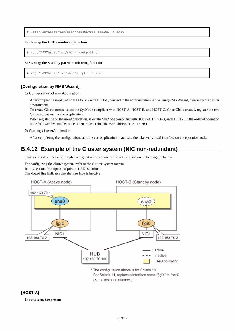
# /opt/FJSVhanet/usr/sbin/hanethvrsc create -n sha0
7) Starting the HUB monitoring function
# /opt/FJSVhanet/usr/sbin/hanetpoll on
8) Starting the Standby patrol monitoring function
# /opt/FJSVhanet/usr/sbin/strptl -n sha1
[Configuration by RMS Wizard]
1) Configuration of userApplication
After completing step 8) of both HOST-B and HOST-C, connect to the administration server using RMS Wizard, then setup the clusterenvironment.To create Gls resources, select the SysNode compliant with HOST-A, HOST-B, and HOST-C. Once Gls is created, register the twoGls resources on the userApplication.When registering on the userApplication, select the SysNode compliant with HOST-A, HOST-B, and HOST-C in the order of operationnode followed by standby node. Then, register the takeover address "192.168.70.1".
2) Starting of userApplication
After completing the configuration, start the userApplication to activate the takeover virtual interface on the operation node.
B.4.12 Example of the Cluster system (NIC non-redundant)This section describes an example configuration procedure of the network shown in the diagram below.
For configuring the cluster system, refer to the Cluster system manual.In this section, description of private LAN is omitted. The dotted line indicates that the interface is inactive.
[HOST-A]
1) Setting up the system
- 397 -
1-1) Define IP addresses and hostnames in /etc/inet/hosts file.
192.168.70.1 hosta # HOST-A/B Virtual IP (Takeover IP)192.168.70.2 host11 # HOST-A Physical IP192.168.70.3 host21 # HOST-B Physical IP192.168.70.100 swhub1 # Primary HUB IP
1-2) For Solaris 10Write the hostnames defined above in /etc/hostname.fjgi0 file. If a file does not exist, create a new file.
- Contents of /etc/hostname.fjgi0
host11
1-2) For Solaris 11Set the host by the interface used with the ipadm(1M) command and also by the host name defined above.
- Interface net0
# /usr/sbin/ipadm create-ip net0# /usr/sbin/ipadm create-addr -T static -a host11/24 net0/v4
1-3) Define the subnet mask in /etc/inet/netmasks file.
192.168.70.0 255.255.255.0
2) Reboot (For Solaris 10)
Run the following command to reboot the system. Make sure fjgi0 are enabled as IPv4 interfaces after rebooting the system.
# /usr/sbin/shutdown -y -i6 -g0
3) Creation of virtual interface
3-1) For Solaris 10
# /opt/FJSVhanet/usr/sbin/hanetconfig create -n sha0 -m d -i 192.168.70.1 -e 192.168.70.2 -t fjgi0
3-1) For Solaris 11
# /opt/FJSVhanet/usr/sbin/hanetconfig create -n sha0 -m d -i 192.168.70.1 -e 192.168.70.2 -t net0
Note
Ensure that the physical IP address specified using option '-e' is the same IP address configured in /etc/hostname.fjgi0 or with the ipadm(1M)command.
4) Setting up the HUB monitoring function
# /opt/FJSVhanet/usr/sbin/hanetpoll create -n sha0 -p 192.168.70.100 -b off
5) Creation of takeover virtual interface
# /opt/FJSVhanet/usr/sbin/hanethvrsc create -n sha0
- 398 -
6) Starting the HUB monitoring function
# /opt/FJSVhanet/usr/sbin/hanetpoll on
[HOST-B]
1) Setting up the system
1-1) Define IP addresses and hostnames in /etc/inet/hosts file. Defined information is the same as for HOST-A.
1-2) For Solaris 10Write the hostnames defined above in /etc/hostname.fjgi0 file. If a file does not exist, create a new file.
- Contents of /etc/hostname.fjgi0
host21
1-2) For Solaris 11Set the host by the interface used with the ipadm(1M) command and also by the host name defined above.
- Interface net0
# /usr/sbin/ipadm create-ip net0# /usr/sbin/ipadm create-addr -T static -a host21/24 net0/v4
1-3) Define the subnet mask in /etc/inet/netmasks file. Defined content is same as HOST-A.
2) Reboot (For Solaris 10)
Run the following command to reboot the system. Make sure fjgi0 are enabled as IPv4 interfaces after rebooting the system.
# /usr/sbin/shutdown -y -i6 -g0
3) Creation of virtual interface
3-1) For Solaris 10
# /opt/FJSVhanet/usr/sbin/hanetconfig create -n sha0 -m d -i 192.168.70.1 -e 192.168.70.3 -t fjgi0
3-1) For Solaris 11
# /opt/FJSVhanet/usr/sbin/hanetconfig create -n sha0 -m d -i 192.168.70.1 -e 192.168.70.3 -t net0
Note
Ensure that the physical IP address specified using option '-e' is the same IP address configured in /etc/hostname.fjgi0 or with the ipadm(1M)command.
4) Setting up the HUB monitoring function
# /opt/FJSVhanet/usr/sbin/hanetpoll create -n sha0 -p 192.168.70.100 -b off
5) Creation of takeover virtual interface
# /opt/FJSVhanet/usr/sbin/hanethvrsc create -n sha0
- 399 -
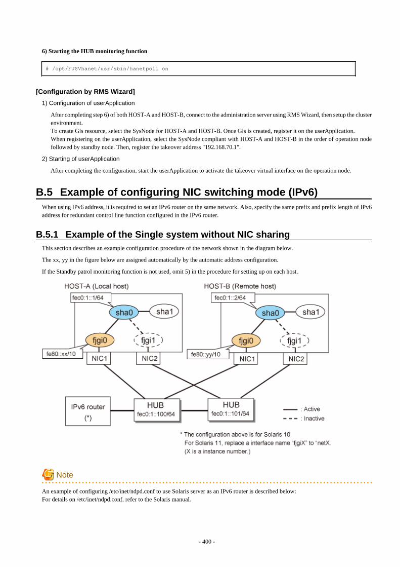
6) Starting the HUB monitoring function
# /opt/FJSVhanet/usr/sbin/hanetpoll on
[Configuration by RMS Wizard]
1) Configuration of userApplication
After completing step 6) of both HOST-A and HOST-B, connect to the administration server using RMS Wizard, then setup the clusterenvironment.To create Gls resource, select the SysNode for HOST-A and HOST-B. Once Gls is created, register it on the userApplication.When registering on the userApplication, select the SysNode compliant with HOST-A and HOST-B in the order of operation nodefollowed by standby node. Then, register the takeover address "192.168.70.1".
2) Starting of userApplication
After completing the configuration, start the userApplication to activate the takeover virtual interface on the operation node.
B.5 Example of configuring NIC switching mode (IPv6)When using IPv6 address, it is required to set an IPv6 router on the same network. Also, specify the same prefix and prefix length of IPv6address for redundant control line function configured in the IPv6 router.
B.5.1 Example of the Single system without NIC sharingThis section describes an example configuration procedure of the network shown in the diagram below.
The xx, yy in the figure below are assigned automatically by the automatic address configuration.
If the Standby patrol monitoring function is not used, omit 5) in the procedure for setting up on each host.
Note
An example of configuring /etc/inet/ndpd.conf to use Solaris server as an IPv6 router is described below:For details on /etc/inet/ndpd.conf, refer to the Solaris manual.
- 400 -
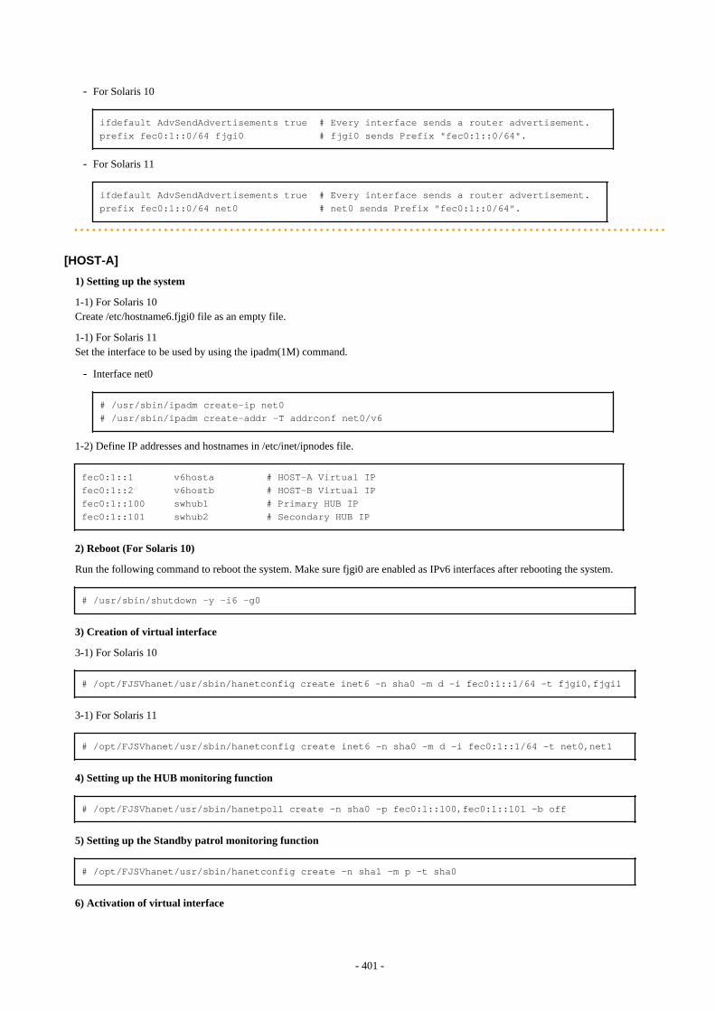
- For Solaris 10
ifdefault AdvSendAdvertisements true # Every interface sends a router advertisement.prefix fec0:1::0/64 fjgi0 # fjgi0 sends Prefix "fec0:1::0/64".
- For Solaris 11
ifdefault AdvSendAdvertisements true # Every interface sends a router advertisement.prefix fec0:1::0/64 net0 # net0 sends Prefix "fec0:1::0/64".
[HOST-A]
1) Setting up the system
1-1) For Solaris 10Create /etc/hostname6.fjgi0 file as an empty file.
1-1) For Solaris 11Set the interface to be used by using the ipadm(1M) command.
- Interface net0
# /usr/sbin/ipadm create-ip net0# /usr/sbin/ipadm create-addr -T addrconf net0/v6
1-2) Define IP addresses and hostnames in /etc/inet/ipnodes file.
fec0:1::1 v6hosta # HOST-A Virtual IPfec0:1::2 v6hostb # HOST-B Virtual IPfec0:1::100 swhub1 # Primary HUB IPfec0:1::101 swhub2 # Secondary HUB IP
2) Reboot (For Solaris 10)
Run the following command to reboot the system. Make sure fjgi0 are enabled as IPv6 interfaces after rebooting the system.
# /usr/sbin/shutdown -y -i6 -g0
3) Creation of virtual interface
3-1) For Solaris 10
# /opt/FJSVhanet/usr/sbin/hanetconfig create inet6 -n sha0 -m d -i fec0:1::1/64 -t fjgi0,fjgi1
3-1) For Solaris 11
# /opt/FJSVhanet/usr/sbin/hanetconfig create inet6 -n sha0 -m d -i fec0:1::1/64 -t net0,net1
4) Setting up the HUB monitoring function
# /opt/FJSVhanet/usr/sbin/hanetpoll create -n sha0 -p fec0:1::100,fec0:1::101 -b off
5) Setting up the Standby patrol monitoring function
# /opt/FJSVhanet/usr/sbin/hanetconfig create -n sha1 -m p -t sha0
6) Activation of virtual interface
- 401 -
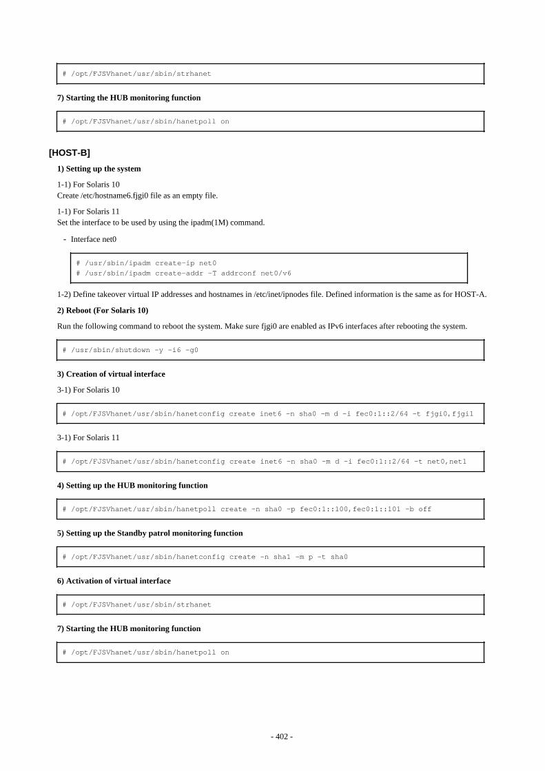
# /opt/FJSVhanet/usr/sbin/strhanet
7) Starting the HUB monitoring function
# /opt/FJSVhanet/usr/sbin/hanetpoll on
[HOST-B]
1) Setting up the system
1-1) For Solaris 10Create /etc/hostname6.fjgi0 file as an empty file.
1-1) For Solaris 11Set the interface to be used by using the ipadm(1M) command.
- Interface net0
# /usr/sbin/ipadm create-ip net0# /usr/sbin/ipadm create-addr -T addrconf net0/v6
1-2) Define takeover virtual IP addresses and hostnames in /etc/inet/ipnodes file. Defined information is the same as for HOST-A.
2) Reboot (For Solaris 10)
Run the following command to reboot the system. Make sure fjgi0 are enabled as IPv6 interfaces after rebooting the system.
# /usr/sbin/shutdown -y -i6 -g0
3) Creation of virtual interface
3-1) For Solaris 10
# /opt/FJSVhanet/usr/sbin/hanetconfig create inet6 -n sha0 -m d -i fec0:1::2/64 -t fjgi0,fjgi1
3-1) For Solaris 11
# /opt/FJSVhanet/usr/sbin/hanetconfig create inet6 -n sha0 -m d -i fec0:1::2/64 -t net0,net1
4) Setting up the HUB monitoring function
# /opt/FJSVhanet/usr/sbin/hanetpoll create -n sha0 -p fec0:1::100,fec0:1::101 -b off
5) Setting up the Standby patrol monitoring function
# /opt/FJSVhanet/usr/sbin/hanetconfig create -n sha1 -m p -t sha0
6) Activation of virtual interface
# /opt/FJSVhanet/usr/sbin/strhanet
7) Starting the HUB monitoring function
# /opt/FJSVhanet/usr/sbin/hanetpoll on
- 402 -
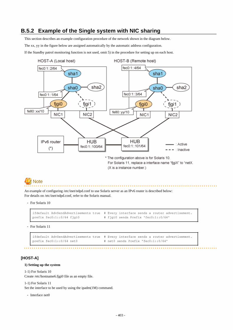
B.5.2 Example of the Single system with NIC sharingThis section describes an example configuration procedure of the network shown in the diagram below.
The xx, yy in the figure below are assigned automatically by the automatic address configuration.
If the Standby patrol monitoring function is not used, omit 5) in the procedure for setting up on each host.
Note
An example of configuring /etc/inet/ndpd.conf to use Solaris server as an IPv6 router is described below:For details on /etc/inet/ndpd.conf, refer to the Solaris manual.
- For Solaris 10
ifdefault AdvSendAdvertisements true # Every interface sends a router advertisement.prefix fec0:1::0/64 fjgi0 # fjgi0 sends Prefix "fec0:1::0/64"
- For Solaris 11
ifdefault AdvSendAdvertisements true # Every interface sends a router advertisement.prefix fec0:1::0/64 net0 # net0 sends Prefix "fec0:1::0/64"
[HOST-A]
1) Setting up the system
1-1) For Solaris 10Create /etc/hostname6.fjgi0 file as an empty file.
1-1) For Solaris 11Set the interface to be used by using the ipadm(1M) command.
- Interface net0
- 403 -
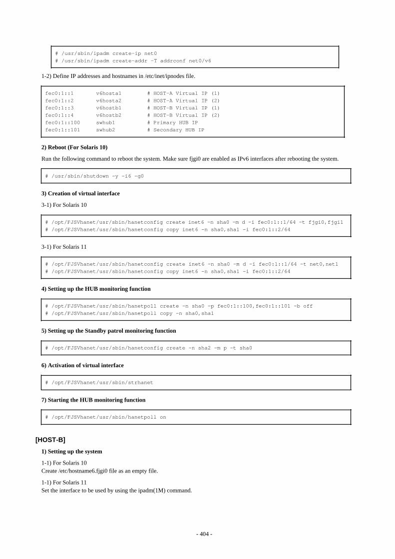
# /usr/sbin/ipadm create-ip net0# /usr/sbin/ipadm create-addr -T addrconf net0/v6
1-2) Define IP addresses and hostnames in /etc/inet/ipnodes file.
fec0:1::1 v6hosta1 # HOST-A Virtual IP (1)fec0:1::2 v6hosta2 # HOST-A Virtual IP (2)fec0:1::3 v6hostb1 # HOST-B Virtual IP (1)fec0:1::4 v6hostb2 # HOST-B Virtual IP (2)fec0:1::100 swhub1 # Primary HUB IPfec0:1::101 swhub2 # Secondary HUB IP
2) Reboot (For Solaris 10)
Run the following command to reboot the system. Make sure fjgi0 are enabled as IPv6 interfaces after rebooting the system.
# /usr/sbin/shutdown -y -i6 -g0
3) Creation of virtual interface
3-1) For Solaris 10
# /opt/FJSVhanet/usr/sbin/hanetconfig create inet6 -n sha0 -m d -i fec0:1::1/64 -t fjgi0,fjgi1# /opt/FJSVhanet/usr/sbin/hanetconfig copy inet6 -n sha0,sha1 -i fec0:1::2/64
3-1) For Solaris 11
# /opt/FJSVhanet/usr/sbin/hanetconfig create inet6 -n sha0 -m d -i fec0:1::1/64 -t net0,net1# /opt/FJSVhanet/usr/sbin/hanetconfig copy inet6 -n sha0,sha1 -i fec0:1::2/64
4) Setting up the HUB monitoring function
# /opt/FJSVhanet/usr/sbin/hanetpoll create -n sha0 -p fec0:1::100,fec0:1::101 -b off# /opt/FJSVhanet/usr/sbin/hanetpoll copy -n sha0,sha1
5) Setting up the Standby patrol monitoring function
# /opt/FJSVhanet/usr/sbin/hanetconfig create -n sha2 -m p -t sha0
6) Activation of virtual interface
# /opt/FJSVhanet/usr/sbin/strhanet
7) Starting the HUB monitoring function
# /opt/FJSVhanet/usr/sbin/hanetpoll on
[HOST-B]
1) Setting up the system
1-1) For Solaris 10Create /etc/hostname6.fjgi0 file as an empty file.
1-1) For Solaris 11Set the interface to be used by using the ipadm(1M) command.
- 404 -
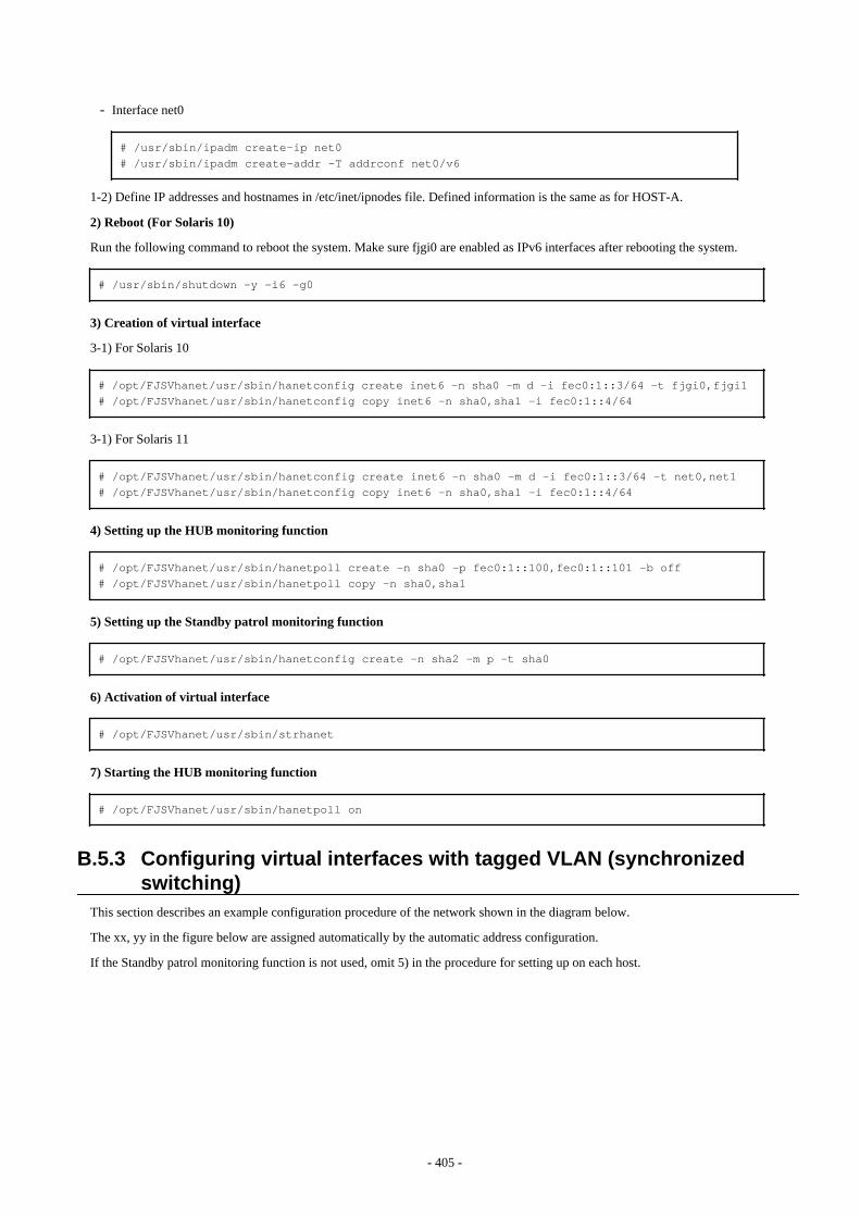
- Interface net0
# /usr/sbin/ipadm create-ip net0# /usr/sbin/ipadm create-addr -T addrconf net0/v6
1-2) Define IP addresses and hostnames in /etc/inet/ipnodes file. Defined information is the same as for HOST-A.
2) Reboot (For Solaris 10)
Run the following command to reboot the system. Make sure fjgi0 are enabled as IPv6 interfaces after rebooting the system.
# /usr/sbin/shutdown -y -i6 -g0
3) Creation of virtual interface
3-1) For Solaris 10
# /opt/FJSVhanet/usr/sbin/hanetconfig create inet6 -n sha0 -m d -i fec0:1::3/64 -t fjgi0,fjgi1# /opt/FJSVhanet/usr/sbin/hanetconfig copy inet6 -n sha0,sha1 -i fec0:1::4/64
3-1) For Solaris 11
# /opt/FJSVhanet/usr/sbin/hanetconfig create inet6 -n sha0 -m d -i fec0:1::3/64 -t net0,net1# /opt/FJSVhanet/usr/sbin/hanetconfig copy inet6 -n sha0,sha1 -i fec0:1::4/64
4) Setting up the HUB monitoring function
# /opt/FJSVhanet/usr/sbin/hanetpoll create -n sha0 -p fec0:1::100,fec0:1::101 -b off# /opt/FJSVhanet/usr/sbin/hanetpoll copy -n sha0,sha1
5) Setting up the Standby patrol monitoring function
# /opt/FJSVhanet/usr/sbin/hanetconfig create -n sha2 -m p -t sha0
6) Activation of virtual interface
# /opt/FJSVhanet/usr/sbin/strhanet
7) Starting the HUB monitoring function
# /opt/FJSVhanet/usr/sbin/hanetpoll on
B.5.3 Configuring virtual interfaces with tagged VLAN (synchronizedswitching)
This section describes an example configuration procedure of the network shown in the diagram below.
The xx, yy in the figure below are assigned automatically by the automatic address configuration.
If the Standby patrol monitoring function is not used, omit 5) in the procedure for setting up on each host.
- 405 -
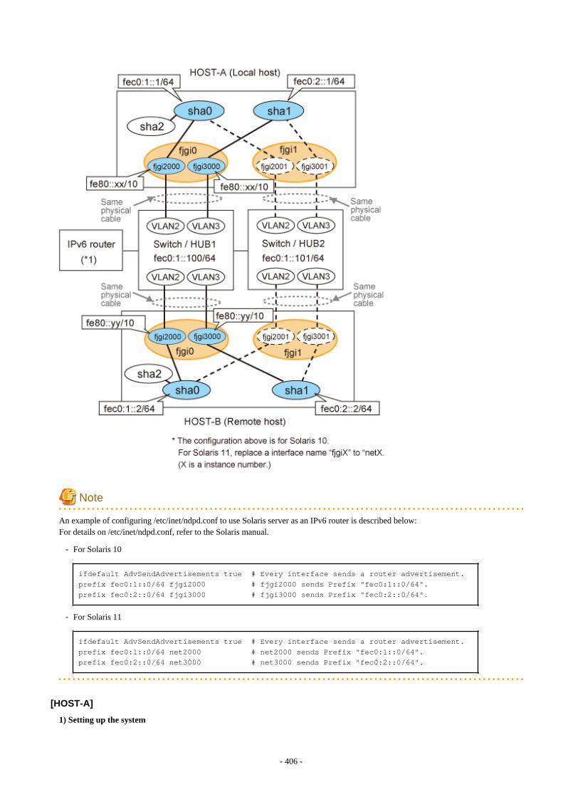
Note
An example of configuring /etc/inet/ndpd.conf to use Solaris server as an IPv6 router is described below:For details on /etc/inet/ndpd.conf, refer to the Solaris manual.
- For Solaris 10
ifdefault AdvSendAdvertisements true # Every interface sends a router advertisement.prefix fec0:1::0/64 fjgi2000 # fjgi2000 sends Prefix "fec0:1::0/64".prefix fec0:2::0/64 fjgi3000 # fjgi3000 sends Prefix "fec0:2::0/64".
- For Solaris 11
ifdefault AdvSendAdvertisements true # Every interface sends a router advertisement.prefix fec0:1::0/64 net2000 # net2000 sends Prefix "fec0:1::0/64".prefix fec0:2::0/64 net3000 # net3000 sends Prefix "fec0:2::0/64".
[HOST-A]
1) Setting up the system
- 406 -

1-1) For Solaris 10Create /etc/hostname6.fjgi2000 and /etc/hostname6.fjgi3000 file as an empty file.
1-1) For Solaris 11Set the interface to be used by using the dladm(1M) command and the ipadm(1M) command.
- Interface net2000
# /usr/sbin/dladm create-vlan -l net0 -v 2# /usr/sbin/ipadm create-ip net2000# /usr/sbin/ipadm create-addr -T addrconf net2000/v6
- Interface net2001
# /usr/sbin/dladm create-vlan -l net1 -v 2
- Interface net3000
# /usr/sbin/dladm create-vlan -l net0 -v 3# /usr/sbin/ipadm create-ip net3000# /usr/sbin/ipadm create-addr -T addrconf net3000/v6
- Interface net3001
# /usr/sbin/dladm create-vlan -l net1 -v 3
1-2) Define IP addresses and hostnames in /etc/inet/ipnodes file.
fec0:1::1 v6hosta1 # HOST-A Virtual IP(1)fec0:2::1 v6hosta2 # HOST-A Virtual IP(2)fec0:1::2 v6hostb1 # HOST-B Virtual IP(1)fec0:2::2 v6hostb2 # HOST-B Virtual IP(2)fec0:1::100 swhub1 # primary HUB IPfec0:1::101 swhub2 # secondary HUB IP
2) Creation of virtual interface
2-1) For Solaris 10
# /opt/FJSVhanet/usr/sbin/hanetconfig create inet6 -n sha0 -m d -i fec0:1::1/64 -t fjgi2000,fjgi2001# /opt/FJSVhanet/usr/sbin/hanetconfig create inet6 -n sha1 -m d -i fec0:2::1/64 -t fjgi3000,fjgi3001
2-1) For Solaris 11
# /opt/FJSVhanet/usr/sbin/hanetconfig create inet6 -n sha0 -m d -i fec0:1::1/64 -t net2000,net2001# /opt/FJSVhanet/usr/sbin/hanetconfig create inet6 -n sha1 -m d -i fec0:2::1/64 -t net3000,net3001
3) Setting up the HUB monitoring function
# /opt/FJSVhanet/usr/sbin/hanetpoll create -n sha0 -p fec0:1::100,fec0:1::101 -b on
4) Setting up the HUB monitoring function (Synchronized switching)
# /opt/FJSVhanet/usr/sbin/hanetpoll copy -n sha0,sha1
- 407 -

5) Setting up the Standby patrol monitoring function
Please define only one Standby patrol monitoring function.
# /opt/FJSVhanet/usr/sbin/hanetconfig create -n sha2 -m p -t sha0
6) Reboot
Run the following command to reboot the system. Using the ifconfig command, make sure that fjgi2000 and fjgi3000 for Solaris 10,net2000 and net 3000 for Solaris 11 are enabled as IPv6 interfaces after rebooting the system.
# /usr/sbin/shutdown -y -i6 -g0
[HOST-B]
1) Setting up the system
1-1) For Solaris 10Create /etc/hostname6.fjgi2000 and /etc/hostname6.fjgi3000 file as an empty file.
1-1) For Solaris 11Set the interface to be used by using the dladm(1M) command and the ipadm(1M) command.
- Interface net2000
# /usr/sbin/dladm create-vlan -l net0 -v 2# /usr/sbin/ipadm create-ip net2000# /usr/sbin/ipadm create-addr -T addrconf net2000/v6
- Interface net2001
# /usr/sbin/dladm create-vlan -l net1 -v 2
- Interface net3000
# /usr/sbin/dladm create-vlan -l net0 -v 3# /usr/sbin/ipadm create-ip net3000# /usr/sbin/ipadm create-addr -T addrconf net3000/v6
- Interface net3001
# /usr/sbin/dladm create-vlan -l net1 -v 3
1-2) Define IP addresses and hostnames in /etc/inet/ipnodes file. Defined information is the same as for HOST-A.
2) Creation of virtual interface
2-1) For Solaris 10
# /opt/FJSVhanet/usr/sbin/hanetconfig create inet6 -n sha0 -m d -i fec0:1::2/64 -t fjgi2000,fjgi2001# /opt/FJSVhanet/usr/sbin/hanetconfig create inet6 -n sha1 -m d -i fec0:2::2/64 -t fjgi3000,fjgi3001
2-1) For Solaris 11
# /opt/FJSVhanet/usr/sbin/hanetconfig create inet6 -n sha0 -m d -i fec0:1::2/64 -t net2000,net2001# /opt/FJSVhanet/usr/sbin/hanetconfig create inet6 -n sha1 -m d -i fec0:2::2/64 -t net3000,net3001
- 408 -
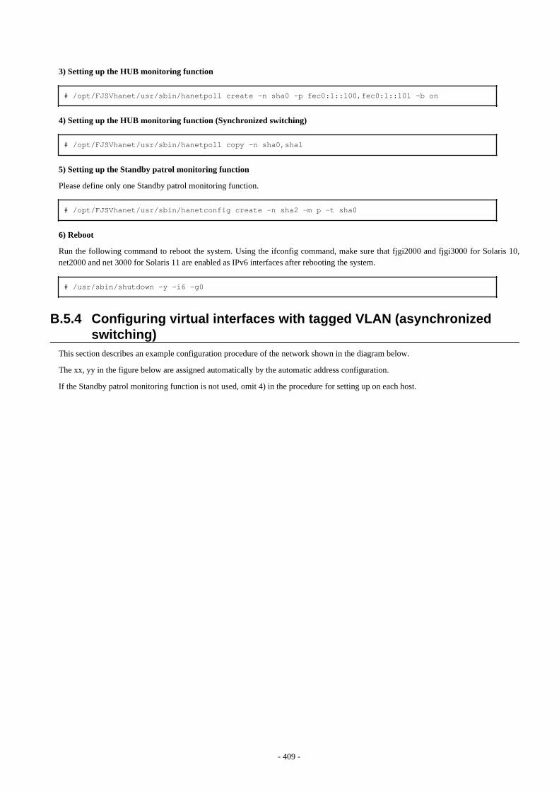
3) Setting up the HUB monitoring function
# /opt/FJSVhanet/usr/sbin/hanetpoll create -n sha0 -p fec0:1::100,fec0:1::101 -b on
4) Setting up the HUB monitoring function (Synchronized switching)
# /opt/FJSVhanet/usr/sbin/hanetpoll copy -n sha0,sha1
5) Setting up the Standby patrol monitoring function
Please define only one Standby patrol monitoring function.
# /opt/FJSVhanet/usr/sbin/hanetconfig create -n sha2 -m p -t sha0
6) Reboot
Run the following command to reboot the system. Using the ifconfig command, make sure that fjgi2000 and fjgi3000 for Solaris 10,net2000 and net 3000 for Solaris 11 are enabled as IPv6 interfaces after rebooting the system.
# /usr/sbin/shutdown -y -i6 -g0
B.5.4 Configuring virtual interfaces with tagged VLAN (asynchronizedswitching)
This section describes an example configuration procedure of the network shown in the diagram below.
The xx, yy in the figure below are assigned automatically by the automatic address configuration.
If the Standby patrol monitoring function is not used, omit 4) in the procedure for setting up on each host.
- 409 -
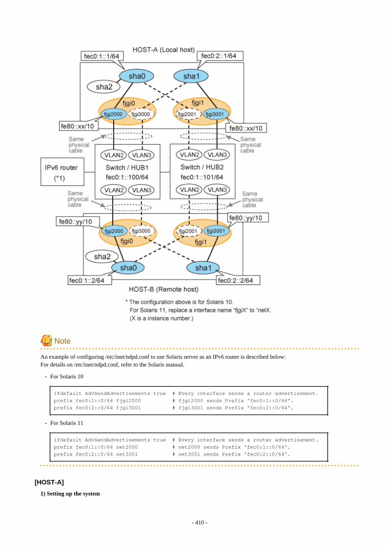
Note
An example of configuring /etc/inet/ndpd.conf to use Solaris server as an IPv6 router is described below:For details on /etc/inet/ndpd.conf, refer to the Solaris manual.
- For Solaris 10
ifdefault AdvSendAdvertisements true # Every interface sends a router advertisement.prefix fec0:1::0/64 fjgi2000 # fjgi2000 sends Prefix "fec0:1::0/64".prefix fec0:2::0/64 fjgi3001 # fjgi3001 sends Prefix "fec0:2::0/64".
- For Solaris 11
ifdefault AdvSendAdvertisements true # Every interface sends a router advertisement.prefix fec0:1::0/64 net2000 # net2000 sends Prefix "fec0:1::0/64".prefix fec0:2::0/64 net3001 # net3001 sends Prefix "fec0:2::0/64".
[HOST-A]
1) Setting up the system
- 410 -
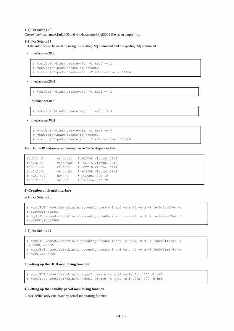
1-1) For Solaris 10Create /etc/hostname6.fjgi2000 and /etc/hostname6.fjgi3001 file as an empty file.
1-1) For Solaris 11Set the interface to be used by using the dladm(1M) command and the ipadm(1M) command.
- Interface net2000
# /usr/sbin/dladm create-vlan -l net0 -v 2# /usr/sbin/ipadm create-ip net2000# /usr/sbin/ipadm create-addr -T addrconf net2000/v6
- Interface net2001
# /usr/sbin/dladm create-vlan -l net1 -v 2
- Interface net3000
# /usr/sbin/dladm create-vlan -l net0 -v 3
- Interface net3001
# /usr/sbin/dladm create-vlan -l net1 -v 3# /usr/sbin/ipadm create-ip net3001# /usr/sbin/ipadm create-addr -T addrconf net3001/v6
1-2) Define IP addresses and hostnames in /etc/inet/ipnodes file.
fec0:1::1 v6hosta1 # HOST-A Virtual IP(1)fec0:2::1 v6hosta2 # HOST-A Virtual IP(2)fec0:1::2 v6hostb1 # HOST-B Virtual IP(1)fec0:2::2 v6hostB2 # HOST-B Virtual IP(2)fec0:1::100 swhub1 # Switch/HUB1 IPfec0:2::100 swhub2 # Switch/HUB2 IP
2) Creation of virtual interface
2-1) For Solaris 10
# /opt/FJSVhanet/usr/sbin/hanetconfig create inet6 -n sha0 -m d -i fec0:1::1/64 -t fjgi2000,fjgi2001# /opt/FJSVhanet/usr/sbin/hanetconfig create inet6 -n sha1 -m d -i fec0:2::1/64 -t fjgi3001,fjgi3000
2-1) For Solaris 11
# /opt/FJSVhanet/usr/sbin/hanetconfig create inet6 -n sha0 -m d -i fec0:1::1/64 -t net2000,net2001# /opt/FJSVhanet/usr/sbin/hanetconfig create inet6 -n sha1 -m d -i fec0:2::1/64 -t net3001,net3000
3) Setting up the HUB monitoring function
# /opt/FJSVhanet/usr/sbin/hanetpoll create -n sha0 -p fec0:1::100 -b off# /opt/FJSVhanet/usr/sbin/hanetpoll create -n sha1 -p fec0:2::100 -b off
4) Setting up the Standby patrol monitoring function
Please define only one Standby patrol monitoring function.
- 411 -

# /opt/FJSVhanet/usr/sbin/hanetconfig create -n sha2 -m p -t sha0
5) Reboot
Run the following command to reboot the system. Using the ifconfig command, make sure that fjgi2000 and fjgi3001 for Solaris 10,net2000 and net 3001 for Solaris 11 are enabled as IPv6 interfaces after rebooting the system.
# /usr/sbin/shutdown -y -i6 -g0
[HOST-B]
1) Setting up the system
1-1) For Solaris 10Create /etc/hostname6.fjgi2000 and /etc/hostname6.fjgi3001 file as an empty file.
1-1) For Solaris 11Set the interface to be used by using the dladm(1M) command and the ipadm(1M) command.
- Interface net2000
# /usr/sbin/dladm create-vlan -l net0 -v 2# /usr/sbin/ipadm create-ip net2000# /usr/sbin/ipadm create-addr -T addrconf net2000/v6
- Interface net2001
# /usr/sbin/dladm create-vlan -l net1 -v 2
- Interface net3000
# /usr/sbin/dladm create-vlan -l net0 -v 3
- Interface net3001
# /usr/sbin/dladm create-vlan -l net1 -v 3# /usr/sbin/ipadm create-ip net3001# /usr/sbin/ipadm create-addr -T addrconf net3001/v6
1-2) Define IP addresses and hostnames in /etc/inet/ipnodes file. Defined information is the same as for HOST-A.
2) Creation of virtual interface
2-1) For Solaris 10
# /opt/FJSVhanet/usr/sbin/hanetconfig create inet6 -n sha0 -m d -i fec0:1::2/64 -t fjgi2000,fjgi2001# /opt/FJSVhanet/usr/sbin/hanetconfig create inet6 -n sha1 -m d -i fec0:2::2/64 -t fjgi3001,fjgi3000
2-1) For Solaris 11
# /opt/FJSVhanet/usr/sbin/hanetconfig create inet6 -n sha0 -m d -i fec0:1::2/64 -t net2000,net2001# /opt/FJSVhanet/usr/sbin/hanetconfig create inet6 -n sha1 -m d -i fec0:2::2/64 -t net3001,net3000
3) Setting up the HUB monitoring function
- 412 -
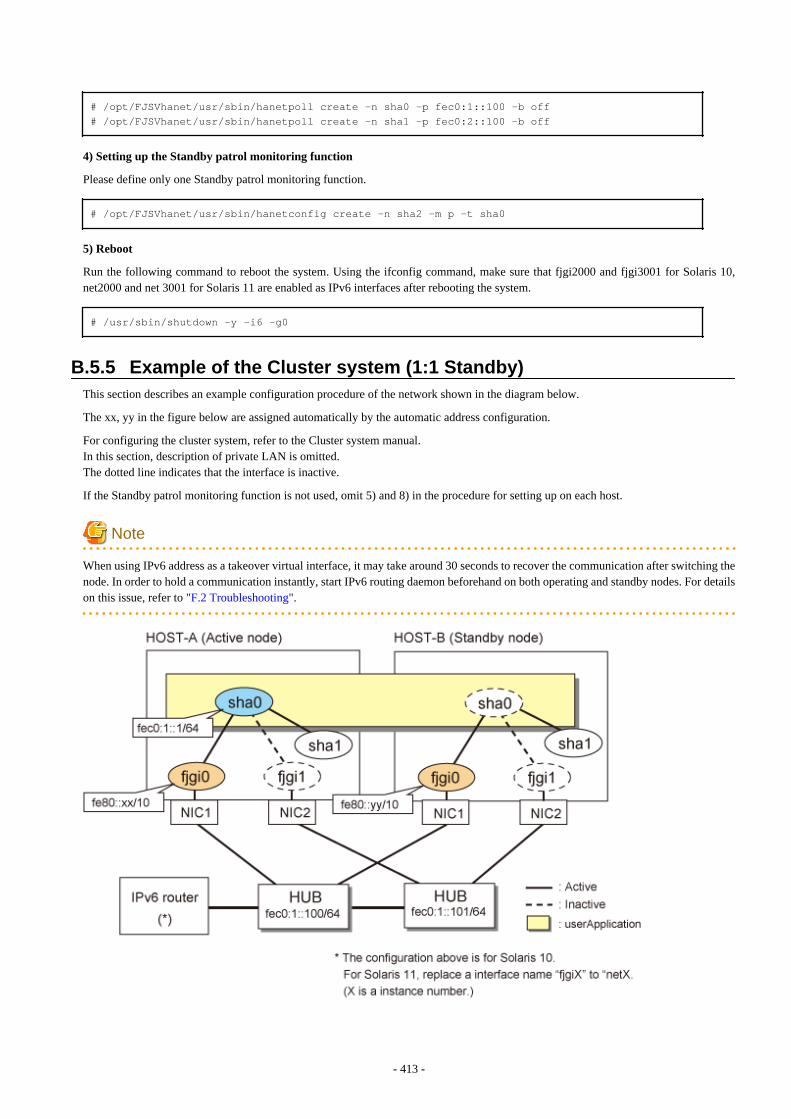
# /opt/FJSVhanet/usr/sbin/hanetpoll create -n sha0 -p fec0:1::100 -b off# /opt/FJSVhanet/usr/sbin/hanetpoll create -n sha1 -p fec0:2::100 -b off
4) Setting up the Standby patrol monitoring function
Please define only one Standby patrol monitoring function.
# /opt/FJSVhanet/usr/sbin/hanetconfig create -n sha2 -m p -t sha0
5) Reboot
Run the following command to reboot the system. Using the ifconfig command, make sure that fjgi2000 and fjgi3001 for Solaris 10,net2000 and net 3001 for Solaris 11 are enabled as IPv6 interfaces after rebooting the system.
# /usr/sbin/shutdown -y -i6 -g0
B.5.5 Example of the Cluster system (1:1 Standby)This section describes an example configuration procedure of the network shown in the diagram below.
The xx, yy in the figure below are assigned automatically by the automatic address configuration.
For configuring the cluster system, refer to the Cluster system manual.In this section, description of private LAN is omitted. The dotted line indicates that the interface is inactive.
If the Standby patrol monitoring function is not used, omit 5) and 8) in the procedure for setting up on each host.
Note
When using IPv6 address as a takeover virtual interface, it may take around 30 seconds to recover the communication after switching thenode. In order to hold a communication instantly, start IPv6 routing daemon beforehand on both operating and standby nodes. For detailson this issue, refer to "F.2 Troubleshooting".
- 413 -
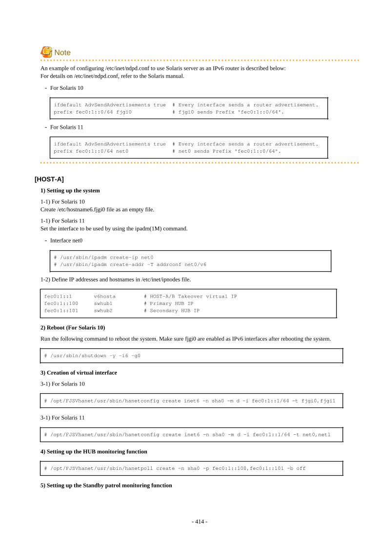
Note
An example of configuring /etc/inet/ndpd.conf to use Solaris server as an IPv6 router is described below:For details on /etc/inet/ndpd.conf, refer to the Solaris manual.
- For Solaris 10
ifdefault AdvSendAdvertisements true # Every interface sends a router advertisement.prefix fec0:1::0/64 fjgi0 # fjgi0 sends Prefix "fec0:1::0/64".
- For Solaris 11
ifdefault AdvSendAdvertisements true # Every interface sends a router advertisement.prefix fec0:1::0/64 net0 # net0 sends Prefix "fec0:1::0/64".
[HOST-A]
1) Setting up the system
1-1) For Solaris 10Create /etc/hostname6.fjgi0 file as an empty file.
1-1) For Solaris 11Set the interface to be used by using the ipadm(1M) command.
- Interface net0
# /usr/sbin/ipadm create-ip net0# /usr/sbin/ipadm create-addr -T addrconf net0/v6
1-2) Define IP addresses and hostnames in /etc/inet/ipnodes file.
fec0:1::1 v6hosta # HOST-A/B Takeover virtual IPfec0:1::100 swhub1 # Primary HUB IPfec0:1::101 swhub2 # Secondary HUB IP
2) Reboot (For Solaris 10)
Run the following command to reboot the system. Make sure fjgi0 are enabled as IPv6 interfaces after rebooting the system.
# /usr/sbin/shutdown -y -i6 -g0
3) Creation of virtual interface
3-1) For Solaris 10
# /opt/FJSVhanet/usr/sbin/hanetconfig create inet6 -n sha0 -m d -i fec0:1::1/64 -t fjgi0,fjgi1
3-1) For Solaris 11
# /opt/FJSVhanet/usr/sbin/hanetconfig create inet6 -n sha0 -m d -i fec0:1::1/64 -t net0,net1
4) Setting up the HUB monitoring function
# /opt/FJSVhanet/usr/sbin/hanetpoll create -n sha0 -p fec0:1::100,fec0:1::101 -b off
5) Setting up the Standby patrol monitoring function
- 414 -
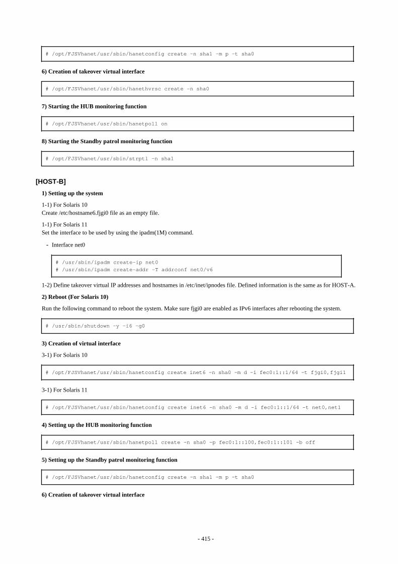
# /opt/FJSVhanet/usr/sbin/hanetconfig create -n sha1 -m p -t sha0
6) Creation of takeover virtual interface
# /opt/FJSVhanet/usr/sbin/hanethvrsc create -n sha0
7) Starting the HUB monitoring function
# /opt/FJSVhanet/usr/sbin/hanetpoll on
8) Starting the Standby patrol monitoring function
# /opt/FJSVhanet/usr/sbin/strptl -n sha1
[HOST-B]
1) Setting up the system
1-1) For Solaris 10Create /etc/hostname6.fjgi0 file as an empty file.
1-1) For Solaris 11Set the interface to be used by using the ipadm(1M) command.
- Interface net0
# /usr/sbin/ipadm create-ip net0# /usr/sbin/ipadm create-addr -T addrconf net0/v6
1-2) Define takeover virtual IP addresses and hostnames in /etc/inet/ipnodes file. Defined information is the same as for HOST-A.
2) Reboot (For Solaris 10)
Run the following command to reboot the system. Make sure fjgi0 are enabled as IPv6 interfaces after rebooting the system.
# /usr/sbin/shutdown -y -i6 -g0
3) Creation of virtual interface
3-1) For Solaris 10
# /opt/FJSVhanet/usr/sbin/hanetconfig create inet6 -n sha0 -m d -i fec0:1::1/64 -t fjgi0,fjgi1
3-1) For Solaris 11
# /opt/FJSVhanet/usr/sbin/hanetconfig create inet6 -n sha0 -m d -i fec0:1::1/64 -t net0,net1
4) Setting up the HUB monitoring function
# /opt/FJSVhanet/usr/sbin/hanetpoll create -n sha0 -p fec0:1::100,fec0:1::101 -b off
5) Setting up the Standby patrol monitoring function
# /opt/FJSVhanet/usr/sbin/hanetconfig create -n sha1 -m p -t sha0
6) Creation of takeover virtual interface
- 415 -

# /opt/FJSVhanet/usr/sbin/hanethvrsc create -n sha0
7) Starting the HUB monitoring function
# /opt/FJSVhanet/usr/sbin/hanetpoll on
8) Starting the Standby patrol monitoring function
# /opt/FJSVhanet/usr/sbin/strptl -n sha1
[Configuration by Cluster Admin View]
1) Configuration of userApplication
After completing step 8) of both HOST-A and HOST-B, connect to the administration server using Cluster Admin View, then setupthe cluster environment.To create Gls resource, select the SysNode compliant with HOST-A and HOST-B. Once Gls is created, register it on theuserApplication.When registering on the userApplication, select the SysNode compliant with HOST-A and HOST-B in the order of operation nodefollowed by standby node. Then, register the takeover address "fec0:1::1".
2) Starting of userApplication
After completing the configuration, start the userApplication to activate the takeover virtual interface on the operation node.
B.5.6 Example of the Cluster system (Mutual standby) without NIC sharingThis section describes an example configuration procedure of the network shown in the diagram below.
The xx, yy in the figure below are assigned automatically by the automatic address configuration.
For configuring the cluster system, refer to the Cluster system manual.In this section, description of private LAN is omitted. The dotted line indicates that the interface is inactive.
If the Standby patrol monitoring function is not used, omit 5) and 8) in the procedure for setting up on each host.
Note
When using IPv6 address as a takeover virtual interface, it may take around 30 seconds to recover the communication after switching thenode. In order to hold a communication instantly, start IPv6 routing daemon beforehand on both operating and standby nodes. For detailson this issue, refer to "F.2 Troubleshooting".
- 416 -
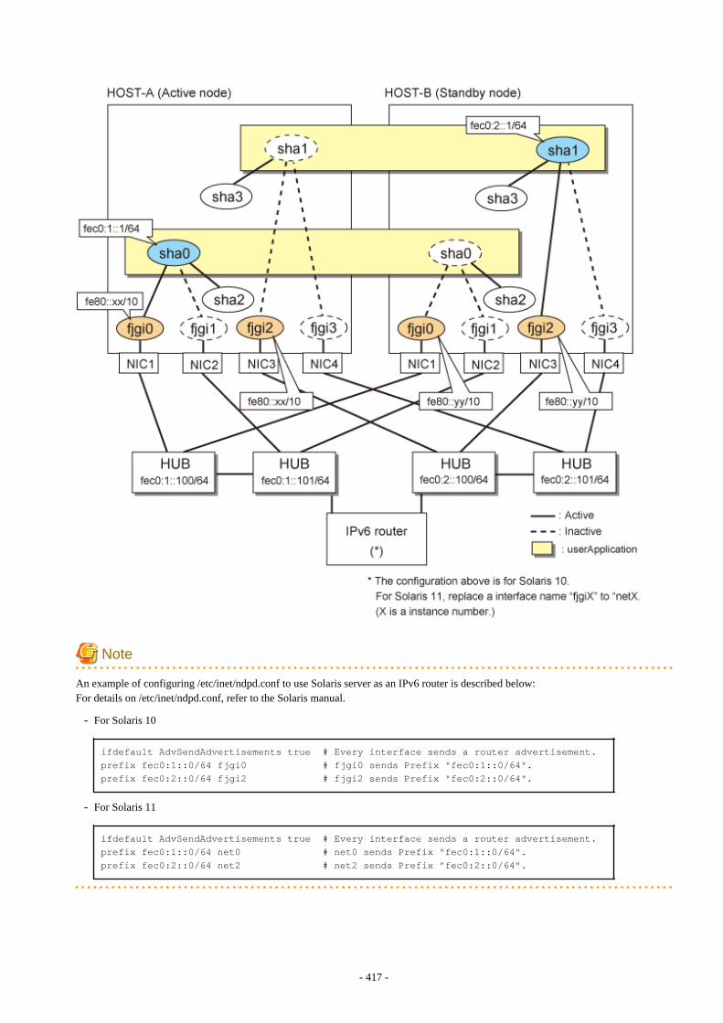
Note
An example of configuring /etc/inet/ndpd.conf to use Solaris server as an IPv6 router is described below:For details on /etc/inet/ndpd.conf, refer to the Solaris manual.
- For Solaris 10
ifdefault AdvSendAdvertisements true # Every interface sends a router advertisement.prefix fec0:1::0/64 fjgi0 # fjgi0 sends Prefix "fec0:1::0/64".prefix fec0:2::0/64 fjgi2 # fjgi2 sends Prefix "fec0:2::0/64".
- For Solaris 11
ifdefault AdvSendAdvertisements true # Every interface sends a router advertisement.prefix fec0:1::0/64 net0 # net0 sends Prefix "fec0:1::0/64".prefix fec0:2::0/64 net2 # net2 sends Prefix "fec0:2::0/64".
- 417 -
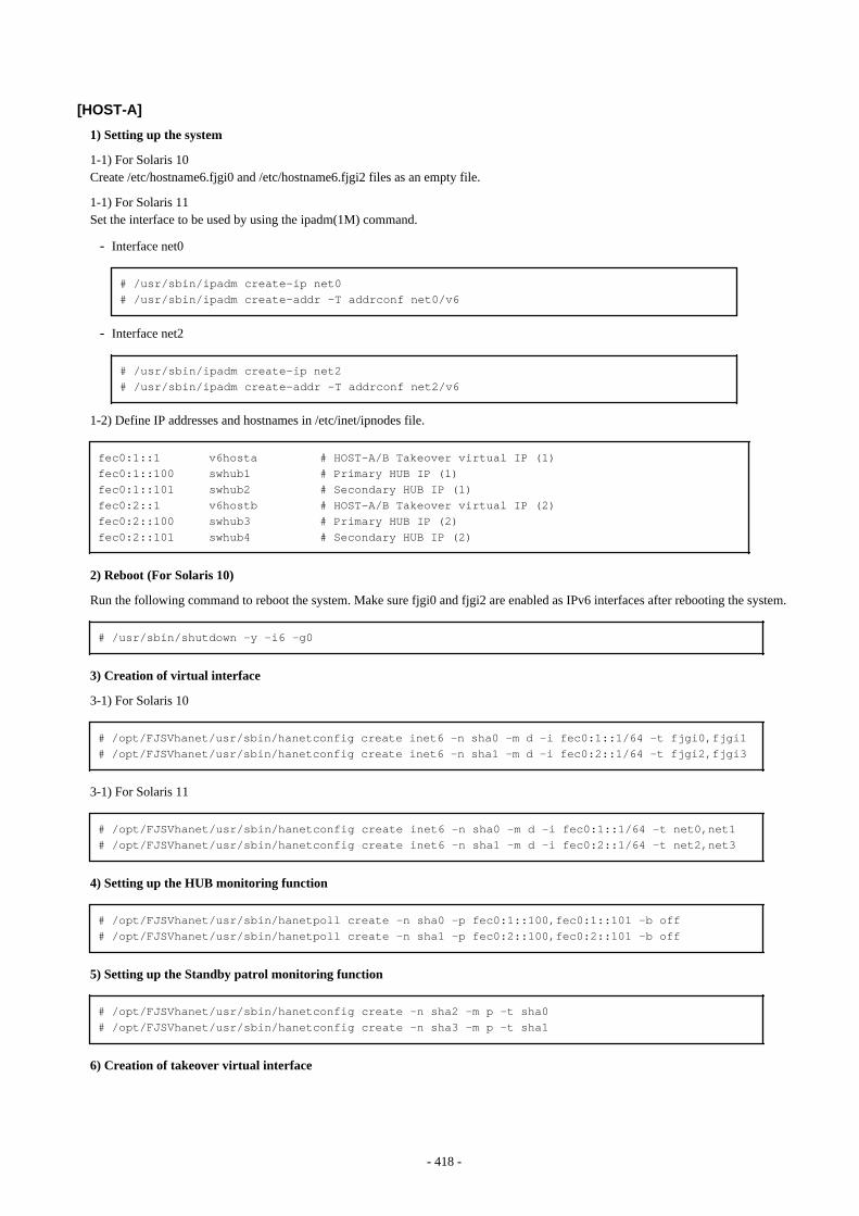
[HOST-A]
1) Setting up the system
1-1) For Solaris 10Create /etc/hostname6.fjgi0 and /etc/hostname6.fjgi2 files as an empty file.
1-1) For Solaris 11Set the interface to be used by using the ipadm(1M) command.
- Interface net0
# /usr/sbin/ipadm create-ip net0# /usr/sbin/ipadm create-addr -T addrconf net0/v6
- Interface net2
# /usr/sbin/ipadm create-ip net2# /usr/sbin/ipadm create-addr -T addrconf net2/v6
1-2) Define IP addresses and hostnames in /etc/inet/ipnodes file.
fec0:1::1 v6hosta # HOST-A/B Takeover virtual IP (1)fec0:1::100 swhub1 # Primary HUB IP (1)fec0:1::101 swhub2 # Secondary HUB IP (1)fec0:2::1 v6hostb # HOST-A/B Takeover virtual IP (2)fec0:2::100 swhub3 # Primary HUB IP (2)fec0:2::101 swhub4 # Secondary HUB IP (2)
2) Reboot (For Solaris 10)
Run the following command to reboot the system. Make sure fjgi0 and fjgi2 are enabled as IPv6 interfaces after rebooting the system.
# /usr/sbin/shutdown -y -i6 -g0
3) Creation of virtual interface
3-1) For Solaris 10
# /opt/FJSVhanet/usr/sbin/hanetconfig create inet6 -n sha0 -m d -i fec0:1::1/64 -t fjgi0,fjgi1# /opt/FJSVhanet/usr/sbin/hanetconfig create inet6 -n sha1 -m d -i fec0:2::1/64 -t fjgi2,fjgi3
3-1) For Solaris 11
# /opt/FJSVhanet/usr/sbin/hanetconfig create inet6 -n sha0 -m d -i fec0:1::1/64 -t net0,net1# /opt/FJSVhanet/usr/sbin/hanetconfig create inet6 -n sha1 -m d -i fec0:2::1/64 -t net2,net3
4) Setting up the HUB monitoring function
# /opt/FJSVhanet/usr/sbin/hanetpoll create -n sha0 -p fec0:1::100,fec0:1::101 -b off# /opt/FJSVhanet/usr/sbin/hanetpoll create -n sha1 -p fec0:2::100,fec0:2::101 -b off
5) Setting up the Standby patrol monitoring function
# /opt/FJSVhanet/usr/sbin/hanetconfig create -n sha2 -m p -t sha0# /opt/FJSVhanet/usr/sbin/hanetconfig create -n sha3 -m p -t sha1
6) Creation of takeover virtual interface
- 418 -
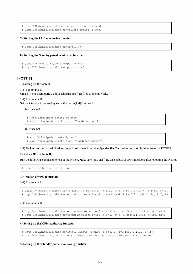
# /opt/FJSVhanet/usr/sbin/hanethvrsc create -n sha0# /opt/FJSVhanet/usr/sbin/hanethvrsc create -n sha1
7) Starting the HUB monitoring function
# /opt/FJSVhanet/usr/sbin/hanetpoll on
8) Starting the Standby patrol monitoring function
# /opt/FJSVhanet/usr/sbin/strptl -n sha2# /opt/FJSVhanet/usr/sbin/strptl -n sha3
[HOST-B]
1) Setting up the system
1-1) For Solaris 10Create /etc/hostname6.fjgi0 and /etc/hostname6.fjgi2 files as an empty file.
1-1) For Solaris 11Set the interface to be used by using the ipadm(1M) command.
- Interface net0
# /usr/sbin/ipadm create-ip net0# /usr/sbin/ipadm create-addr -T addrconf net0/v6
- Interface net2
# /usr/sbin/ipadm create-ip net2# /usr/sbin/ipadm create-addr -T addrconf net2/v6
1-2) Define takeover virtual IP addresses and hostnames in /etc/inet/ipnodes file. Defined information is the same as for HOST-A.
2) Reboot (For Solaris 10)
Run the following command to reboot the system. Make sure fjgi0 and fjgi2 are enabled as IPv6 interfaces after rebooting the system.
# /usr/sbin/shutdown -y -i6 -g0
3) Creation of virtual interface
3-1) For Solaris 10
# /opt/FJSVhanet/usr/sbin/hanetconfig create inet6 -n sha0 -m d -i fec0:1::1/64 -t fjgi0,fjgi1# /opt/FJSVhanet/usr/sbin/hanetconfig create inet6 -n sha1 -m d -i fec0:2::1/64 -t fjgi2,fjgi3
3-1) For Solaris 11
# /opt/FJSVhanet/usr/sbin/hanetconfig create inet6 -n sha0 -m d -i fec0:1::1/64 -t net0,net1# /opt/FJSVhanet/usr/sbin/hanetconfig create inet6 -n sha1 -m d -i fec0:2::1/64 -t net2,net3
4) Setting up the HUB monitoring function
# /opt/FJSVhanet/usr/sbin/hanetpoll create -n sha0 -p fec0:1::100,fec0:1::101 -b off# /opt/FJSVhanet/usr/sbin/hanetpoll create -n sha1 -p fec0:2::100,fec0:2::101 -b off
5) Setting up the Standby patrol monitoring function
- 419 -
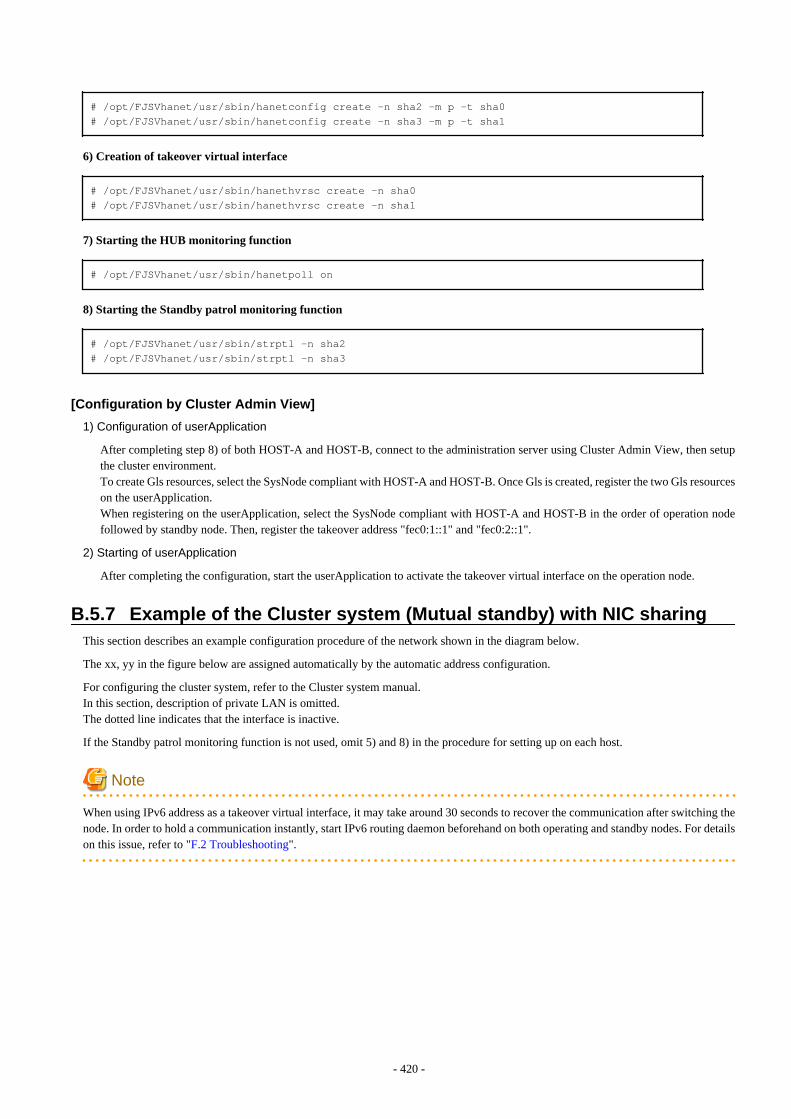
# /opt/FJSVhanet/usr/sbin/hanetconfig create -n sha2 -m p -t sha0# /opt/FJSVhanet/usr/sbin/hanetconfig create -n sha3 -m p -t sha1
6) Creation of takeover virtual interface
# /opt/FJSVhanet/usr/sbin/hanethvrsc create -n sha0# /opt/FJSVhanet/usr/sbin/hanethvrsc create -n sha1
7) Starting the HUB monitoring function
# /opt/FJSVhanet/usr/sbin/hanetpoll on
8) Starting the Standby patrol monitoring function
# /opt/FJSVhanet/usr/sbin/strptl -n sha2# /opt/FJSVhanet/usr/sbin/strptl -n sha3
[Configuration by Cluster Admin View]
1) Configuration of userApplication
After completing step 8) of both HOST-A and HOST-B, connect to the administration server using Cluster Admin View, then setupthe cluster environment.To create Gls resources, select the SysNode compliant with HOST-A and HOST-B. Once Gls is created, register the two Gls resourceson the userApplication.When registering on the userApplication, select the SysNode compliant with HOST-A and HOST-B in the order of operation nodefollowed by standby node. Then, register the takeover address "fec0:1::1" and "fec0:2::1".
2) Starting of userApplication
After completing the configuration, start the userApplication to activate the takeover virtual interface on the operation node.
B.5.7 Example of the Cluster system (Mutual standby) with NIC sharingThis section describes an example configuration procedure of the network shown in the diagram below.
The xx, yy in the figure below are assigned automatically by the automatic address configuration.
For configuring the cluster system, refer to the Cluster system manual.In this section, description of private LAN is omitted. The dotted line indicates that the interface is inactive.
If the Standby patrol monitoring function is not used, omit 5) and 8) in the procedure for setting up on each host.
Note
When using IPv6 address as a takeover virtual interface, it may take around 30 seconds to recover the communication after switching thenode. In order to hold a communication instantly, start IPv6 routing daemon beforehand on both operating and standby nodes. For detailson this issue, refer to "F.2 Troubleshooting".
- 420 -
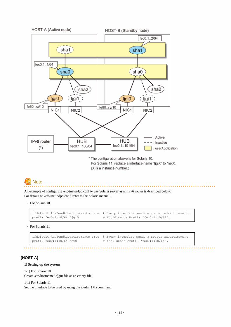
Note
An example of configuring /etc/inet/ndpd.conf to use Solaris server as an IPv6 router is described below:For details on /etc/inet/ndpd.conf, refer to the Solaris manual.
- For Solaris 10
ifdefault AdvSendAdvertisements true # Every interface sends a router advertisement.prefix fec0:1::0/64 fjgi0 # fjgi0 sends Prefix "fec0:1::0/64".
- For Solaris 11
ifdefault AdvSendAdvertisements true # Every interface sends a router advertisement.prefix fec0:1::0/64 net0 # net0 sends Prefix "fec0:1::0/64".
[HOST-A]
1) Setting up the system
1-1) For Solaris 10Create /etc/hostname6.fjgi0 file as an empty file.
1-1) For Solaris 11Set the interface to be used by using the ipadm(1M) command.
- 421 -
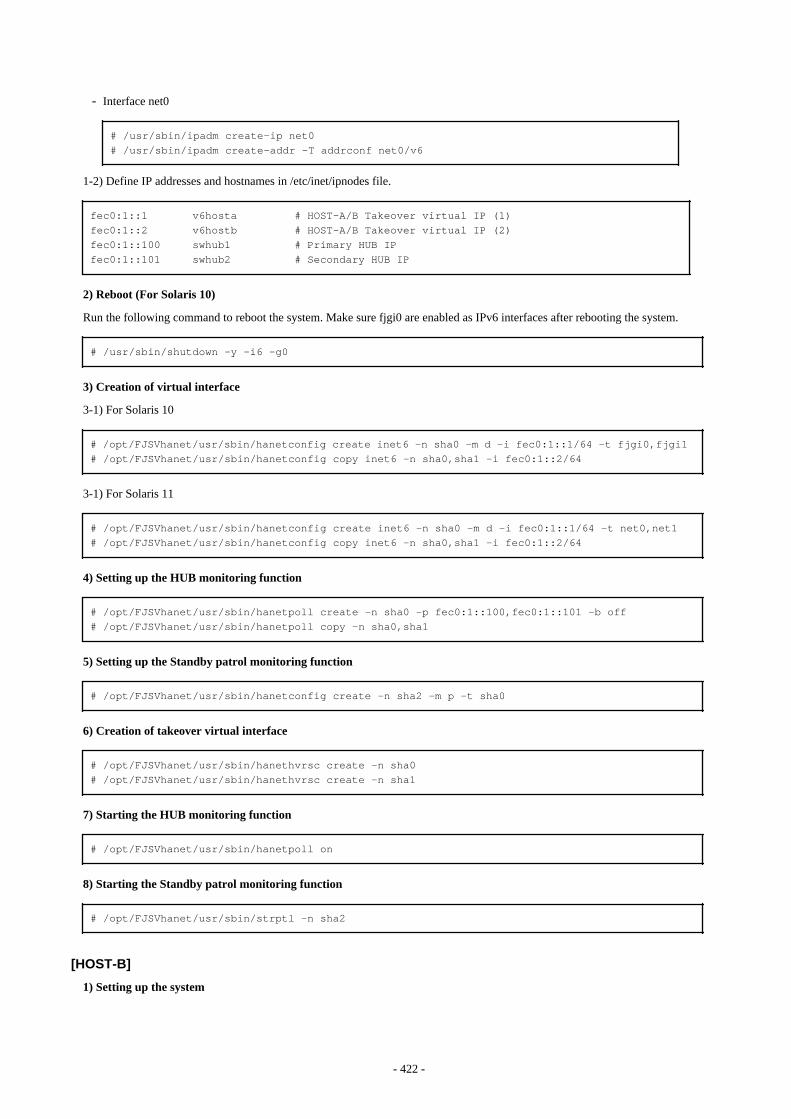
- Interface net0
# /usr/sbin/ipadm create-ip net0# /usr/sbin/ipadm create-addr -T addrconf net0/v6
1-2) Define IP addresses and hostnames in /etc/inet/ipnodes file.
fec0:1::1 v6hosta # HOST-A/B Takeover virtual IP (1)fec0:1::2 v6hostb # HOST-A/B Takeover virtual IP (2)fec0:1::100 swhub1 # Primary HUB IPfec0:1::101 swhub2 # Secondary HUB IP
2) Reboot (For Solaris 10)
Run the following command to reboot the system. Make sure fjgi0 are enabled as IPv6 interfaces after rebooting the system.
# /usr/sbin/shutdown -y -i6 -g0
3) Creation of virtual interface
3-1) For Solaris 10
# /opt/FJSVhanet/usr/sbin/hanetconfig create inet6 -n sha0 -m d -i fec0:1::1/64 -t fjgi0,fjgi1# /opt/FJSVhanet/usr/sbin/hanetconfig copy inet6 -n sha0,sha1 -i fec0:1::2/64
3-1) For Solaris 11
# /opt/FJSVhanet/usr/sbin/hanetconfig create inet6 -n sha0 -m d -i fec0:1::1/64 -t net0,net1# /opt/FJSVhanet/usr/sbin/hanetconfig copy inet6 -n sha0,sha1 -i fec0:1::2/64
4) Setting up the HUB monitoring function
# /opt/FJSVhanet/usr/sbin/hanetpoll create -n sha0 -p fec0:1::100,fec0:1::101 -b off# /opt/FJSVhanet/usr/sbin/hanetpoll copy -n sha0,sha1
5) Setting up the Standby patrol monitoring function
# /opt/FJSVhanet/usr/sbin/hanetconfig create -n sha2 -m p -t sha0
6) Creation of takeover virtual interface
# /opt/FJSVhanet/usr/sbin/hanethvrsc create -n sha0# /opt/FJSVhanet/usr/sbin/hanethvrsc create -n sha1
7) Starting the HUB monitoring function
# /opt/FJSVhanet/usr/sbin/hanetpoll on
8) Starting the Standby patrol monitoring function
# /opt/FJSVhanet/usr/sbin/strptl -n sha2
[HOST-B]
1) Setting up the system
- 422 -
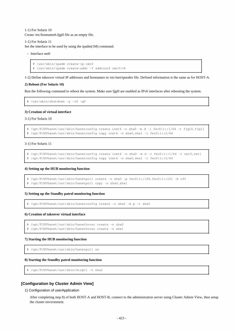
1-1) For Solaris 10Create /etc/hostname6.fjgi0 file as an empty file.
1-1) For Solaris 11Set the interface to be used by using the ipadm(1M) command.
- Interface net0
# /usr/sbin/ipadm create-ip net0# /usr/sbin/ipadm create-addr -T addrconf net0/v6
1-2) Define takeover virtual IP addresses and hostnames in /etc/inet/ipnodes file. Defined information is the same as for HOST-A.
2) Reboot (For Solaris 10)
Run the following command to reboot the system. Make sure fjgi0 are enabled as IPv6 interfaces after rebooting the system.
# /usr/sbin/shutdown -y -i6 -g0
3) Creation of virtual interface
3-1) For Solaris 10
# /opt/FJSVhanet/usr/sbin/hanetconfig create inet6 -n sha0 -m d -i fec0:1::1/64 -t fjgi0,fjgi1# /opt/FJSVhanet/usr/sbin/hanetconfig copy inet6 -n sha0,sha1 -i fec0:1::2/64
3-1) For Solaris 11
# /opt/FJSVhanet/usr/sbin/hanetconfig create inet6 -n sha0 -m d -i fec0:1::1/64 -t net0,net1# /opt/FJSVhanet/usr/sbin/hanetconfig copy inet6 -n sha0,sha1 -i fec0:1::2/64
4) Setting up the HUB monitoring function
# /opt/FJSVhanet/usr/sbin/hanetpoll create -n sha0 -p fec0:1::100,fec0:1::101 -b off# /opt/FJSVhanet/usr/sbin/hanetpoll copy -n sha0,sha1
5) Setting up the Standby patrol monitoring function
# /opt/FJSVhanet/usr/sbin/hanetconfig create -n sha2 -m p -t sha0
6) Creation of takeover virtual interface
# /opt/FJSVhanet/usr/sbin/hanethvrsc create -n sha0# /opt/FJSVhanet/usr/sbin/hanethvrsc create -n sha1
7) Starting the HUB monitoring function
# /opt/FJSVhanet/usr/sbin/hanetpoll on
8) Starting the Standby patrol monitoring function
# /opt/FJSVhanet/usr/sbin/strptl -n sha2
[Configuration by Cluster Admin View]
1) Configuration of userApplication
After completing step 8) of both HOST-A and HOST-B, connect to the administration server using Cluster Admin View, then setupthe cluster environment.
- 423 -
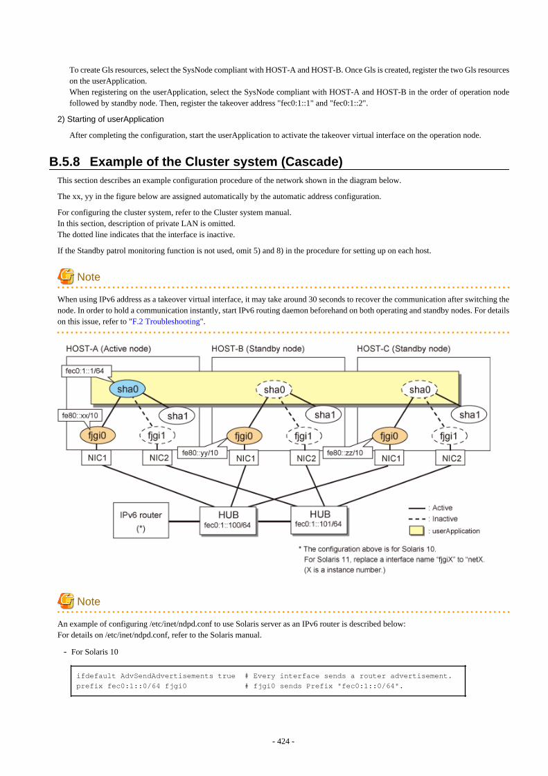
To create Gls resources, select the SysNode compliant with HOST-A and HOST-B. Once Gls is created, register the two Gls resourceson the userApplication.When registering on the userApplication, select the SysNode compliant with HOST-A and HOST-B in the order of operation nodefollowed by standby node. Then, register the takeover address "fec0:1::1" and "fec0:1::2".
2) Starting of userApplication
After completing the configuration, start the userApplication to activate the takeover virtual interface on the operation node.
B.5.8 Example of the Cluster system (Cascade)This section describes an example configuration procedure of the network shown in the diagram below.
The xx, yy in the figure below are assigned automatically by the automatic address configuration.
For configuring the cluster system, refer to the Cluster system manual.In this section, description of private LAN is omitted. The dotted line indicates that the interface is inactive.
If the Standby patrol monitoring function is not used, omit 5) and 8) in the procedure for setting up on each host.
Note
When using IPv6 address as a takeover virtual interface, it may take around 30 seconds to recover the communication after switching thenode. In order to hold a communication instantly, start IPv6 routing daemon beforehand on both operating and standby nodes. For detailson this issue, refer to "F.2 Troubleshooting".
Note
An example of configuring /etc/inet/ndpd.conf to use Solaris server as an IPv6 router is described below:For details on /etc/inet/ndpd.conf, refer to the Solaris manual.
- For Solaris 10
ifdefault AdvSendAdvertisements true # Every interface sends a router advertisement.prefix fec0:1::0/64 fjgi0 # fjgi0 sends Prefix "fec0:1::0/64".
- 424 -
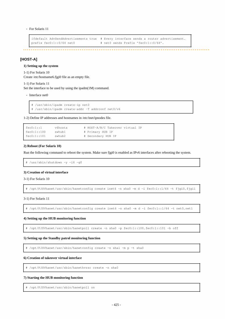
- For Solaris 11
ifdefault AdvSendAdvertisements true # Every interface sends a router advertisement.prefix fec0:1::0/64 net0 # net0 sends Prefix "fec0:1::0/64".
[HOST-A]
1) Setting up the system
1-1) For Solaris 10Create /etc/hostname6.fjgi0 file as an empty file.
1-1) For Solaris 11Set the interface to be used by using the ipadm(1M) command.
- Interface net0
# /usr/sbin/ipadm create-ip net0# /usr/sbin/ipadm create-addr -T addrconf net0/v6
1-2) Define IP addresses and hostnames in /etc/inet/ipnodes file.
fec0:1::1 v6hosta # HOST-A/B/C Takeover virtual IPfec0:1::100 swhub1 # Primary HUB IPfec0:1::101 swhub2 # Secondary HUB IP
2) Reboot (For Solaris 10)
Run the following command to reboot the system. Make sure fjgi0 is enabled as IPv6 interfaces after rebooting the system.
# /usr/sbin/shutdown -y -i6 -g0
3) Creation of virtual interface
3-1) For Solaris 10
# /opt/FJSVhanet/usr/sbin/hanetconfig create inet6 -n sha0 -m d -i fec0:1::1/64 -t fjgi0,fjgi1
3-1) For Solaris 11
# /opt/FJSVhanet/usr/sbin/hanetconfig create inet6 -n sha0 -m d -i fec0:1::1/64 -t net0,net1
4) Setting up the HUB monitoring function
# /opt/FJSVhanet/usr/sbin/hanetpoll create -n sha0 -p fec0:1::100,fec0:1::101 -b off
5) Setting up the Standby patrol monitoring function
# /opt/FJSVhanet/usr/sbin/hanetconfig create -n sha1 -m p -t sha0
6) Creation of takeover virtual interface
# /opt/FJSVhanet/usr/sbin/hanethvrsc create -n sha0
7) Starting the HUB monitoring function
# /opt/FJSVhanet/usr/sbin/hanetpoll on
- 425 -
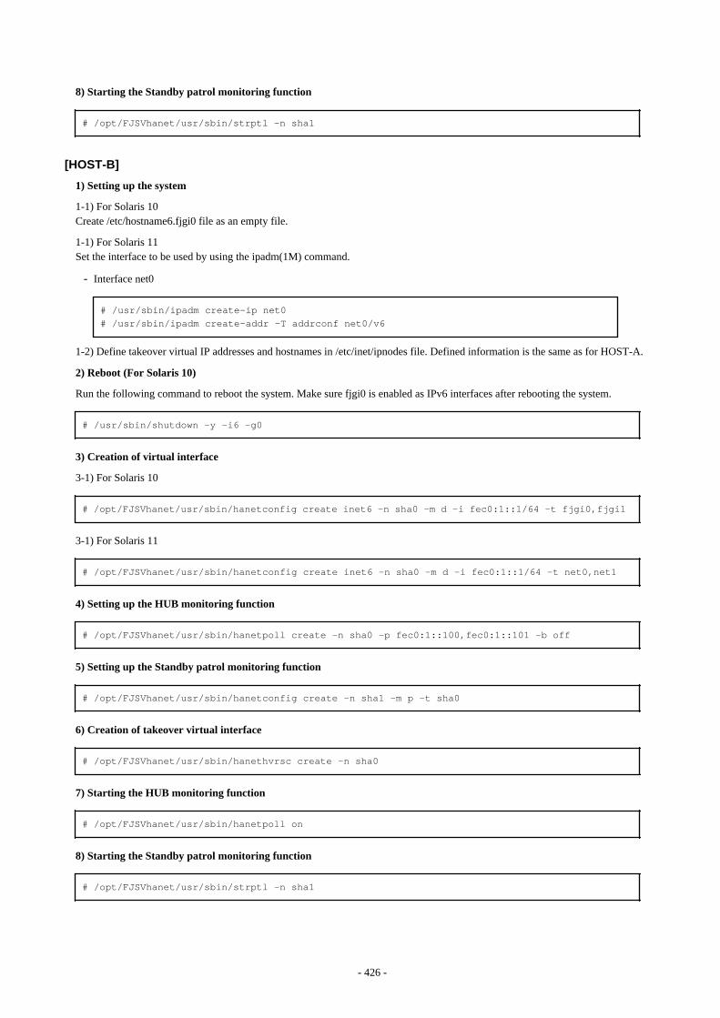
8) Starting the Standby patrol monitoring function
# /opt/FJSVhanet/usr/sbin/strptl -n sha1
[HOST-B]
1) Setting up the system
1-1) For Solaris 10Create /etc/hostname6.fjgi0 file as an empty file.
1-1) For Solaris 11Set the interface to be used by using the ipadm(1M) command.
- Interface net0
# /usr/sbin/ipadm create-ip net0# /usr/sbin/ipadm create-addr -T addrconf net0/v6
1-2) Define takeover virtual IP addresses and hostnames in /etc/inet/ipnodes file. Defined information is the same as for HOST-A.
2) Reboot (For Solaris 10)
Run the following command to reboot the system. Make sure fjgi0 is enabled as IPv6 interfaces after rebooting the system.
# /usr/sbin/shutdown -y -i6 -g0
3) Creation of virtual interface
3-1) For Solaris 10
# /opt/FJSVhanet/usr/sbin/hanetconfig create inet6 -n sha0 -m d -i fec0:1::1/64 -t fjgi0,fjgi1
3-1) For Solaris 11
# /opt/FJSVhanet/usr/sbin/hanetconfig create inet6 -n sha0 -m d -i fec0:1::1/64 -t net0,net1
4) Setting up the HUB monitoring function
# /opt/FJSVhanet/usr/sbin/hanetpoll create -n sha0 -p fec0:1::100,fec0:1::101 -b off
5) Setting up the Standby patrol monitoring function
# /opt/FJSVhanet/usr/sbin/hanetconfig create -n sha1 -m p -t sha0
6) Creation of takeover virtual interface
# /opt/FJSVhanet/usr/sbin/hanethvrsc create -n sha0
7) Starting the HUB monitoring function
# /opt/FJSVhanet/usr/sbin/hanetpoll on
8) Starting the Standby patrol monitoring function
# /opt/FJSVhanet/usr/sbin/strptl -n sha1
- 426 -
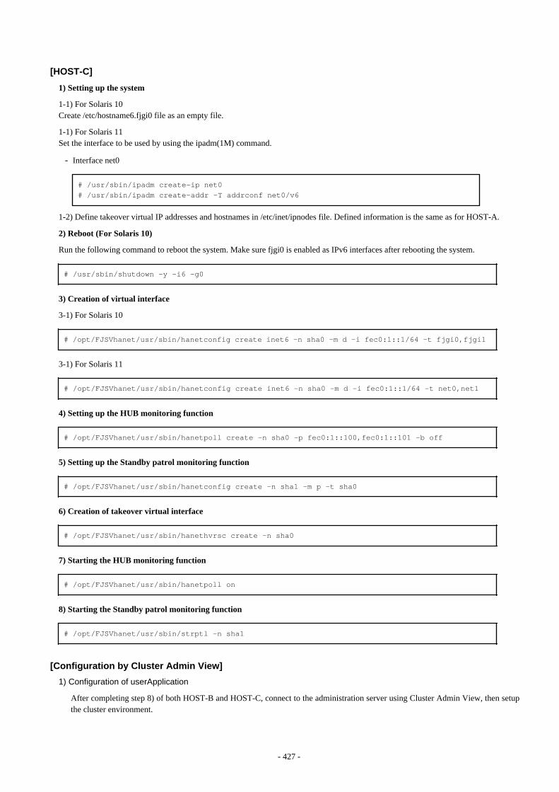
[HOST-C]
1) Setting up the system
1-1) For Solaris 10Create /etc/hostname6.fjgi0 file as an empty file.
1-1) For Solaris 11Set the interface to be used by using the ipadm(1M) command.
- Interface net0
# /usr/sbin/ipadm create-ip net0# /usr/sbin/ipadm create-addr -T addrconf net0/v6
1-2) Define takeover virtual IP addresses and hostnames in /etc/inet/ipnodes file. Defined information is the same as for HOST-A.
2) Reboot (For Solaris 10)
Run the following command to reboot the system. Make sure fjgi0 is enabled as IPv6 interfaces after rebooting the system.
# /usr/sbin/shutdown -y -i6 -g0
3) Creation of virtual interface
3-1) For Solaris 10
# /opt/FJSVhanet/usr/sbin/hanetconfig create inet6 -n sha0 -m d -i fec0:1::1/64 -t fjgi0,fjgi1
3-1) For Solaris 11
# /opt/FJSVhanet/usr/sbin/hanetconfig create inet6 -n sha0 -m d -i fec0:1::1/64 -t net0,net1
4) Setting up the HUB monitoring function
# /opt/FJSVhanet/usr/sbin/hanetpoll create -n sha0 -p fec0:1::100,fec0:1::101 -b off
5) Setting up the Standby patrol monitoring function
# /opt/FJSVhanet/usr/sbin/hanetconfig create -n sha1 -m p -t sha0
6) Creation of takeover virtual interface
# /opt/FJSVhanet/usr/sbin/hanethvrsc create -n sha0
7) Starting the HUB monitoring function
# /opt/FJSVhanet/usr/sbin/hanetpoll on
8) Starting the Standby patrol monitoring function
# /opt/FJSVhanet/usr/sbin/strptl -n sha1
[Configuration by Cluster Admin View]
1) Configuration of userApplication
After completing step 8) of both HOST-B and HOST-C, connect to the administration server using Cluster Admin View, then setupthe cluster environment.
- 427 -
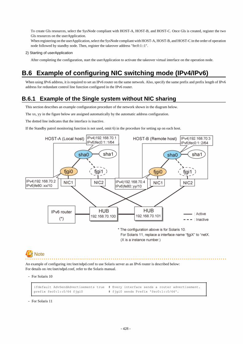
To create Gls resources, select the SysNode compliant with HOST-A, HOST-B, and HOST-C. Once Gls is created, register the twoGls resources on the userApplication.When registering on the userApplication, select the SysNode compliant with HOST-A, HOST-B, and HOST-C in the order of operationnode followed by standby node. Then, register the takeover address "fec0:1::1".
2) Starting of userApplication
After completing the configuration, start the userApplication to activate the takeover virtual interface on the operation node.
B.6 Example of configuring NIC switching mode (IPv4/IPv6)When using IPv6 address, it is required to set an IPv6 router on the same network. Also, specify the same prefix and prefix length of IPv6address for redundant control line function configured in the IPv6 router.
B.6.1 Example of the Single system without NIC sharingThis section describes an example configuration procedure of the network shown in the diagram below.
The xx, yy in the figure below are assigned automatically by the automatic address configuration.
The dotted line indicates that the interface is inactive.
If the Standby patrol monitoring function is not used, omit 6) in the procedure for setting up on each host.
Note
An example of configuring /etc/inet/ndpd.conf to use Solaris server as an IPv6 router is described below:For details on /etc/inet/ndpd.conf, refer to the Solaris manual.
- For Solaris 10
ifdefault AdvSendAdvertisements true # Every interface sends a router advertisement.prefix fec0:1::0/64 fjgi0 # fjgi0 sends Prefix "fec0:1::0/64".
- For Solaris 11
- 428 -
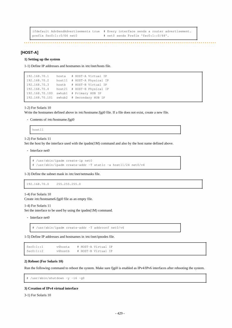
ifdefault AdvSendAdvertisements true # Every interface sends a router advertisement.prefix fec0:1::0/64 net0 # net0 sends Prefix "fec0:1::0/64".
[HOST-A]
1) Setting up the system
1-1) Define IP addresses and hostnames in /etc/inet/hosts file.
192.168.70.1 hosta # HOST-A Virtual IP192.168.70.2 host11 # HOST-A Physical IP192.168.70.3 hostb # HOST-B Virtual IP192.168.70.4 host21 # HOST-B Physical IP192.168.70.100 swhub1 # Primary HUB IP192.168.70.101 swhub2 # Secondary HUB IP
1-2) For Solaris 10Write the hostnames defined above in /etc/hostname.fjgi0 file. If a file does not exist, create a new file.
- Contents of /etc/hostname.fjgi0
host11
1-2) For Solaris 11Set the host by the interface used with the ipadm(1M) command and also by the host name defined above.
- Interface net0
# /usr/sbin/ipadm create-ip net0# /usr/sbin/ipadm create-addr -T static -a host11/24 net0/v4
1-3) Define the subnet mask in /etc/inet/netmasks file.
192.168.70.0 255.255.255.0
1-4) For Solaris 10Create /etc/hostname6.fjgi0 file as an empty file.
1-4) For Solaris 11Set the interface to be used by using the ipadm(1M) command.
- Interface net0
# /usr/sbin/ipadm create-addr -T addrconf net0/v6
1-5) Define IP addresses and hostnames in /etc/inet/ipnodes file.
fec0:1::1 v6hosta # HOST-A Virtual IPfec0:1::2 v6hostb # HOST-B Virtual IP
2) Reboot (For Solaris 10)
Run the following command to reboot the system. Make sure fjgi0 is enabled as IPv4/IPv6 interfaces after rebooting the system.
# /usr/sbin/shutdown -y -i6 -g0
3) Creation of IPv4 virtual interface
3-1) For Solaris 10
- 429 -
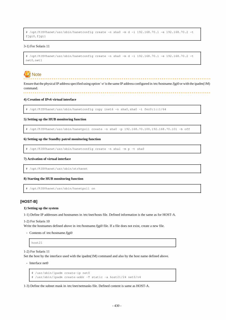
# /opt/FJSVhanet/usr/sbin/hanetconfig create -n sha0 -m d -i 192.168.70.1 -e 192.168.70.2 -t fjgi0,fjgi1
3-1) For Solaris 11
# /opt/FJSVhanet/usr/sbin/hanetconfig create -n sha0 -m d -i 192.168.70.1 -e 192.168.70.2 -t net0,net1
Note
Ensure that the physical IP address specified using option '-e' is the same IP address configured in /etc/hostname.fjgi0 or with the ipadm(1M)command.
4) Creation of IPv6 virtual interface
# /opt/FJSVhanet/usr/sbin/hanetconfig copy inet6 -n sha0,sha0 -i fec0:1::1/64
5) Setting up the HUB monitoring function
# /opt/FJSVhanet/usr/sbin/hanetpoll create -n sha0 -p 192.168.70.100,192.168.70.101 -b off
6) Setting up the Standby patrol monitoring function
# /opt/FJSVhanet/usr/sbin/hanetconfig create -n sha1 -m p -t sha0
7) Activation of virtual interface
# /opt/FJSVhanet/usr/sbin/strhanet
8) Starting the HUB monitoring function
# /opt/FJSVhanet/usr/sbin/hanetpoll on
[HOST-B]
1) Setting up the system
1-1) Define IP addresses and hostnames in /etc/inet/hosts file. Defined information is the same as for HOST-A.
1-2) For Solaris 10Write the hostnames defined above in /etc/hostname.fjgi0 file. If a file does not exist, create a new file.
- Contents of /etc/hostname.fjgi0
host21
1-2) For Solaris 11Set the host by the interface used with the ipadm(1M) command and also by the host name defined above.
- Interface net0
# /usr/sbin/ipadm create-ip net0# /usr/sbin/ipadm create-addr -T static -a host21/24 net0/v4
1-3) Define the subnet mask in /etc/inet/netmasks file. Defined content is same as HOST-A.
- 430 -
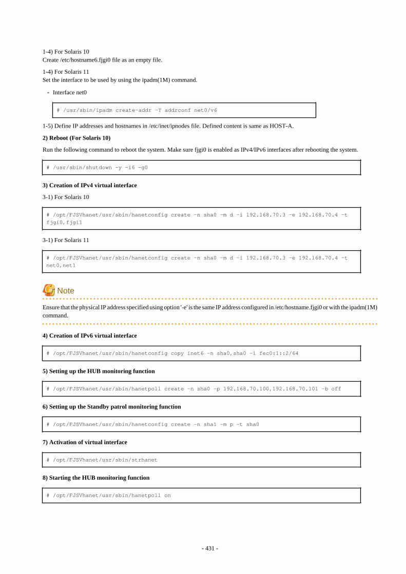
1-4) For Solaris 10Create /etc/hostname6.fjgi0 file as an empty file.
1-4) For Solaris 11Set the interface to be used by using the ipadm(1M) command.
- Interface net0
# /usr/sbin/ipadm create-addr -T addrconf net0/v6
1-5) Define IP addresses and hostnames in /etc/inet/ipnodes file. Defined content is same as HOST-A.
2) Reboot (For Solaris 10)
Run the following command to reboot the system. Make sure fjgi0 is enabled as IPv4/IPv6 interfaces after rebooting the system.
# /usr/sbin/shutdown -y -i6 -g0
3) Creation of IPv4 virtual interface
3-1) For Solaris 10
# /opt/FJSVhanet/usr/sbin/hanetconfig create -n sha0 -m d -i 192.168.70.3 -e 192.168.70.4 -t fjgi0,fjgi1
3-1) For Solaris 11
# /opt/FJSVhanet/usr/sbin/hanetconfig create -n sha0 -m d -i 192.168.70.3 -e 192.168.70.4 -t net0,net1
Note
Ensure that the physical IP address specified using option '-e' is the same IP address configured in /etc/hostname.fjgi0 or with the ipadm(1M)command.
4) Creation of IPv6 virtual interface
# /opt/FJSVhanet/usr/sbin/hanetconfig copy inet6 -n sha0,sha0 -i fec0:1::2/64
5) Setting up the HUB monitoring function
# /opt/FJSVhanet/usr/sbin/hanetpoll create -n sha0 -p 192.168.70.100,192.168.70.101 -b off
6) Setting up the Standby patrol monitoring function
# /opt/FJSVhanet/usr/sbin/hanetconfig create -n sha1 -m p -t sha0
7) Activation of virtual interface
# /opt/FJSVhanet/usr/sbin/strhanet
8) Starting the HUB monitoring function
# /opt/FJSVhanet/usr/sbin/hanetpoll on
- 431 -
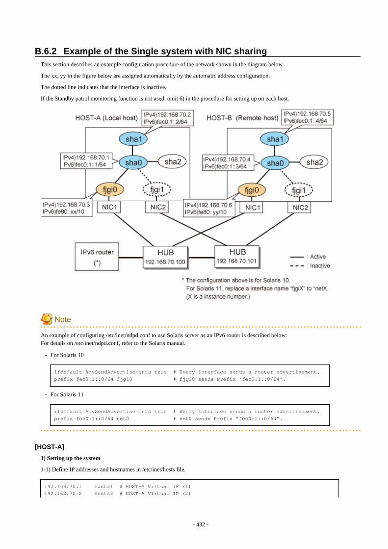
B.6.2 Example of the Single system with NIC sharingThis section describes an example configuration procedure of the network shown in the diagram below.
The xx, yy in the figure below are assigned automatically by the automatic address configuration.
The dotted line indicates that the interface is inactive.
If the Standby patrol monitoring function is not used, omit 6) in the procedure for setting up on each host.
Note
An example of configuring /etc/inet/ndpd.conf to use Solaris server as an IPv6 router is described below:For details on /etc/inet/ndpd.conf, refer to the Solaris manual.
- For Solaris 10
ifdefault AdvSendAdvertisements true # Every interface sends a router advertisement.prefix fec0:1::0/64 fjgi0 # fjgi0 sends Prefix "fec0:1::0/64".
- For Solaris 11
ifdefault AdvSendAdvertisements true # Every interface sends a router advertisement.prefix fec0:1::0/64 net0 # net0 sends Prefix "fec0:1::0/64".
[HOST-A]
1) Setting up the system
1-1) Define IP addresses and hostnames in /etc/inet/hosts file.
192.168.70.1 hosta1 # HOST-A Virtual IP (1)192.168.70.2 hosta2 # HOST-A Virtual IP (2)
- 432 -
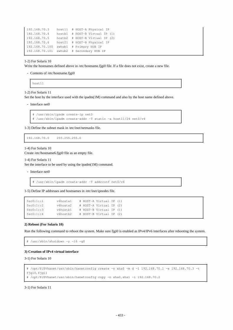
192.168.70.3 host11 # HOST-A Physical IP192.168.70.4 hostb1 # HOST-B Virtual IP (1)192.168.70.5 hostb2 # HOST-B Virtual IP (2)192.168.70.6 host21 # HOST-B Physical IP192.168.70.100 swhub1 # Primary HUB IP192.168.70.101 swhub2 # Secondary HUB IP
1-2) For Solaris 10Write the hostnames defined above in /etc/hostname.fjgi0 file. If a file does not exist, create a new file.
- Contents of /etc/hostname.fjgi0
host11
1-2) For Solaris 11Set the host by the interface used with the ipadm(1M) command and also by the host name defined above.
- Interface net0
# /usr/sbin/ipadm create-ip net0# /usr/sbin/ipadm create-addr -T static -a host11/24 net0/v4
1-3) Define the subnet mask in /etc/inet/netmasks file.
192.168.70.0 255.255.255.0
1-4) For Solaris 10Create /etc/hostname6.fjgi0 file as an empty file.
1-4) For Solaris 11Set the interface to be used by using the ipadm(1M) command.
- Interface net0
# /usr/sbin/ipadm create-addr -T addrconf net0/v6
1-5) Define IP addresses and hostnames in /etc/inet/ipnodes file.
fec0:1::1 v6hosta1 # HOST-A Virtual IP (1)fec0:1::2 v6hosta2 # HOST-A Virtual IP (2)fec0:1::3 v6hostb1 # HOST-B Virtual IP (1)fec0:1::4 v6hostb2 # HOST-B Virtual IP (2)
2) Reboot (For Solaris 10)
Run the following command to reboot the system. Make sure fjgi0 is enabled as IPv4/IPv6 interfaces after rebooting the system.
# /usr/sbin/shutdown -y -i6 -g0
3) Creation of IPv4 virtual interface
3-1) For Solaris 10
# /opt/FJSVhanet/usr/sbin/hanetconfig create -n sha0 -m d -i 192.168.70.1 -e 192.168.70.3 -t fjgi0,fjgi1# /opt/FJSVhanet/usr/sbin/hanetconfig copy -n sha0,sha1 -i 192.168.70.2
3-1) For Solaris 11
- 433 -
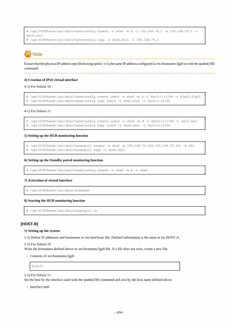
# /opt/FJSVhanet/usr/sbin/hanetconfig create -n sha0 -m d -i 192.168.70.1 -e 192.168.70.3 -t net0,net1# /opt/FJSVhanet/usr/sbin/hanetconfig copy -n sha0,sha1 -i 192.168.70.2
Note
Ensure that the physical IP address specified using option '-e' is the same IP address configured in /etc/hostname.fjgi0 or with the ipadm(1M)command.
4) Creation of IPv6 virtual interface
4-1) For Solaris 10
# /opt/FJSVhanet/usr/sbin/hanetconfig create inet6 -n sha0 -m d -i fec0:1::1/64 -t fjgi0,fjgi1# /opt/FJSVhanet/usr/sbin/hanetconfig copy inet6 -n sha0,sha1 -i fec0:1::2/64
4-1) For Solaris 11
# /opt/FJSVhanet/usr/sbin/hanetconfig create inet6 -n sha0 -m d -i fec0:1::1/64 -t net0,net1# /opt/FJSVhanet/usr/sbin/hanetconfig copy inet6 -n sha0,sha1 -i fec0:1::2/64
5) Setting up the HUB monitoring function
# /opt/FJSVhanet/usr/sbin/hanetpoll create -n sha0 -p 192.168.70.100,192.168.70.101 -b off# /opt/FJSVhanet/usr/sbin/hanetpoll copy -n sha0,sha1
6) Setting up the Standby patrol monitoring function
# /opt/FJSVhanet/usr/sbin/hanetconfig create -n sha2 -m p -t sha0
7) Activation of virtual interface
# /opt/FJSVhanet/usr/sbin/strhanet
8) Starting the HUB monitoring function
# /opt/FJSVhanet/usr/sbin/hanetpoll on
[HOST-B]
1) Setting up the system
1-1) Define IP addresses and hostnames in /etc/inet/hosts file. Defined information is the same as for HOST-A.
1-2) For Solaris 10Write the hostnames defined above in /etc/hostname.fjgi0 file. If a file does not exist, create a new file.
- Contents of /etc/hostname.fjgi0
host21
1-2) For Solaris 11Set the host by the interface used with the ipadm(1M) command and also by the host name defined above.
- Interface net0
- 434 -
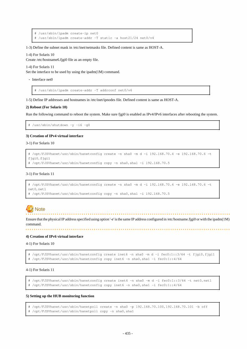
# /usr/sbin/ipadm create-ip net0# /usr/sbin/ipadm create-addr -T static -a host21/24 net0/v4
1-3) Define the subnet mask in /etc/inet/netmasks file. Defined content is same as HOST-A.
1-4) For Solaris 10Create /etc/hostname6.fjgi0 file as an empty file.
1-4) For Solaris 11Set the interface to be used by using the ipadm(1M) command.
- Interface net0
# /usr/sbin/ipadm create-addr -T addrconf net0/v6
1-5) Define IP addresses and hostnames in /etc/inet/ipnodes file. Defined content is same as HOST-A.
2) Reboot (For Solaris 10)
Run the following command to reboot the system. Make sure fjgi0 is enabled as IPv4/IPv6 interfaces after rebooting the system.
# /usr/sbin/shutdown -y -i6 -g0
3) Creation of IPv4 virtual interface
3-1) For Solaris 10
# /opt/FJSVhanet/usr/sbin/hanetconfig create -n sha0 -m d -i 192.168.70.4 -e 192.168.70.6 -t fjgi0,fjgi1# /opt/FJSVhanet/usr/sbin/hanetconfig copy -n sha0,sha1 -i 192.168.70.5
3-1) For Solaris 11
# /opt/FJSVhanet/usr/sbin/hanetconfig create -n sha0 -m d -i 192.168.70.4 -e 192.168.70.6 -t net0,net1# /opt/FJSVhanet/usr/sbin/hanetconfig copy -n sha0,sha1 -i 192.168.70.5
Note
Ensure that the physical IP address specified using option '-e' is the same IP address configured in /etc/hostname.fjgi0 or with the ipadm(1M)command.
4) Creation of IPv6 virtual interface
4-1) For Solaris 10
# /opt/FJSVhanet/usr/sbin/hanetconfig create inet6 -n sha0 -m d -i fec0:1::3/64 -t fjgi0,fjgi1# /opt/FJSVhanet/usr/sbin/hanetconfig copy inet6 -n sha0,sha1 -i fec0:1::4/64
4-1) For Solaris 11
# /opt/FJSVhanet/usr/sbin/hanetconfig create inet6 -n sha0 -m d -i fec0:1::3/64 -t net0,net1# /opt/FJSVhanet/usr/sbin/hanetconfig copy inet6 -n sha0,sha1 -i fec0:1::4/64
5) Setting up the HUB monitoring function
# /opt/FJSVhanet/usr/sbin/hanetpoll create -n sha0 -p 192.168.70.100,192.168.70.101 -b off# /opt/FJSVhanet/usr/sbin/hanetpoll copy -n sha0,sha1
- 435 -
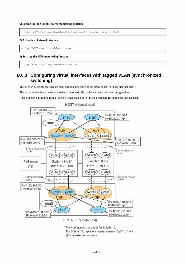
6) Setting up the Standby patrol monitoring function
# /opt/FJSVhanet/usr/sbin/hanetconfig create -n sha2 -m p -t sha0
7) Activation of virtual interface
# /opt/FJSVhanet/usr/sbin/strhanet
8) Starting the HUB monitoring function
# /opt/FJSVhanet/usr/sbin/hanetpoll on
B.6.3 Configuring virtual interfaces with tagged VLAN (synchronizedswitching)
This section describes an example configuration procedure of the network shown in the diagram below.
The xx, yy in the figure below are assigned automatically by the automatic address configuration.
If the Standby patrol monitoring function is not used, omit 6) in the procedure for setting up on each host.
- 436 -
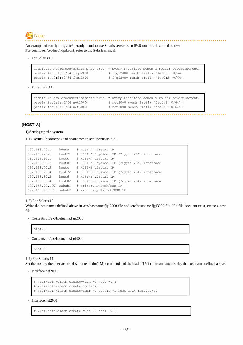
Note
An example of configuring /etc/inet/ndpd.conf to use Solaris server as an IPv6 router is described below:For details on /etc/inet/ndpd.conf, refer to the Solaris manual.
- For Solaris 10
ifdefault AdvSendAdvertisements true # Every interface sends a router advertisement.prefix fec0:1::0/64 fjgi2000 # fjgi2000 sends Prefix "fec0:1::0/64".prefix fec0:2::0/64 fjgi3000 # fjgi3000 sends Prefix "fec0:2::0/64".
- For Solaris 11
ifdefault AdvSendAdvertisements true # Every interface sends a router advertisement.prefix fec0:1::0/64 net2000 # net2000 sends Prefix "fec0:1::0/64".prefix fec0:2::0/64 net3000 # net3000 sends Prefix "fec0:2::0/64".
[HOST-A]
1) Setting up the system
1-1) Define IP addresses and hostnames in /etc/inet/hosts file.
192.168.70.1 hosta # HOST-A Virtual IP192.168.70.3 host71 # HOST-A Physical IP (Tagged VLAN interface)192.168.80.1 hostb # HOST-A Virtual IP192.168.80.3 host81 # HOST-A Physical IP (Tagged VLAN interface)192.168.70.2 hostc # HOST-B Virtual IP192.168.70.4 host72 # HOST-B Physical IP (Tagged VLAN interface)192.168.80.2 hostd # HOST-B Virtual IP192.168.80.4 host82 # HOST-B Physical IP (Tagged VLAN interface)192.168.70.100 swhub1 # primary Switch/HUB IP192.168.70.101 swhub2 # secondary Switch/HUB IP
1-2) For Solaris 10Write the hostnames defined above in /etc/hostname.fjgi2000 file and /etc/hostname.fjgi3000 file. If a file does not exist, create a newfile.
- Contents of /etc/hostname.fjgi2000
host71
- Contents of /etc/hostname.fjgi3000
host81
1-2) For Solaris 11Set the host by the interface used with the dladm(1M) command and the ipadm(1M) command and also by the host name defined above.
- Interface net2000
# /usr/sbin/dladm create-vlan -l net0 -v 2# /usr/sbin/ipadm create-ip net2000# /usr/sbin/ipadm create-addr -T static -a host71/24 net2000/v4
- Interface net2001
# /usr/sbin/dladm create-vlan -l net1 -v 2
- 437 -
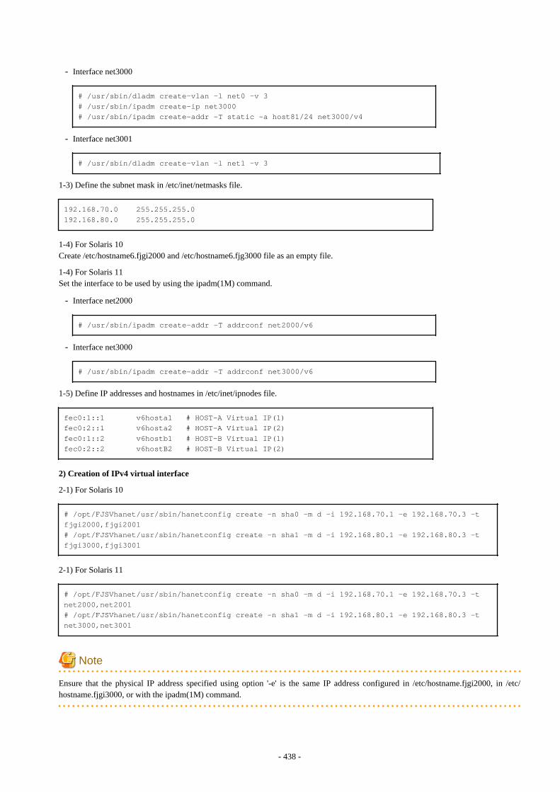
- Interface net3000
# /usr/sbin/dladm create-vlan -l net0 -v 3# /usr/sbin/ipadm create-ip net3000# /usr/sbin/ipadm create-addr -T static -a host81/24 net3000/v4
- Interface net3001
# /usr/sbin/dladm create-vlan -l net1 -v 3
1-3) Define the subnet mask in /etc/inet/netmasks file.
192.168.70.0 255.255.255.0192.168.80.0 255.255.255.0
1-4) For Solaris 10Create /etc/hostname6.fjgi2000 and /etc/hostname6.fjg3000 file as an empty file.
1-4) For Solaris 11Set the interface to be used by using the ipadm(1M) command.
- Interface net2000
# /usr/sbin/ipadm create-addr -T addrconf net2000/v6
- Interface net3000
# /usr/sbin/ipadm create-addr -T addrconf net3000/v6
1-5) Define IP addresses and hostnames in /etc/inet/ipnodes file.
fec0:1::1 v6hosta1 # HOST-A Virtual IP(1)fec0:2::1 v6hosta2 # HOST-A Virtual IP(2)fec0:1::2 v6hostb1 # HOST-B Virtual IP(1)fec0:2::2 v6hostB2 # HOST-B Virtual IP(2)
2) Creation of IPv4 virtual interface
2-1) For Solaris 10
# /opt/FJSVhanet/usr/sbin/hanetconfig create -n sha0 -m d -i 192.168.70.1 -e 192.168.70.3 -t fjgi2000,fjgi2001# /opt/FJSVhanet/usr/sbin/hanetconfig create -n sha1 -m d -i 192.168.80.1 -e 192.168.80.3 -t fjgi3000,fjgi3001
2-1) For Solaris 11
# /opt/FJSVhanet/usr/sbin/hanetconfig create -n sha0 -m d -i 192.168.70.1 -e 192.168.70.3 -t net2000,net2001# /opt/FJSVhanet/usr/sbin/hanetconfig create -n sha1 -m d -i 192.168.80.1 -e 192.168.80.3 -t net3000,net3001
Note
Ensure that the physical IP address specified using option '-e' is the same IP address configured in /etc/hostname.fjgi2000, in /etc/hostname.fjgi3000, or with the ipadm(1M) command.
- 438 -
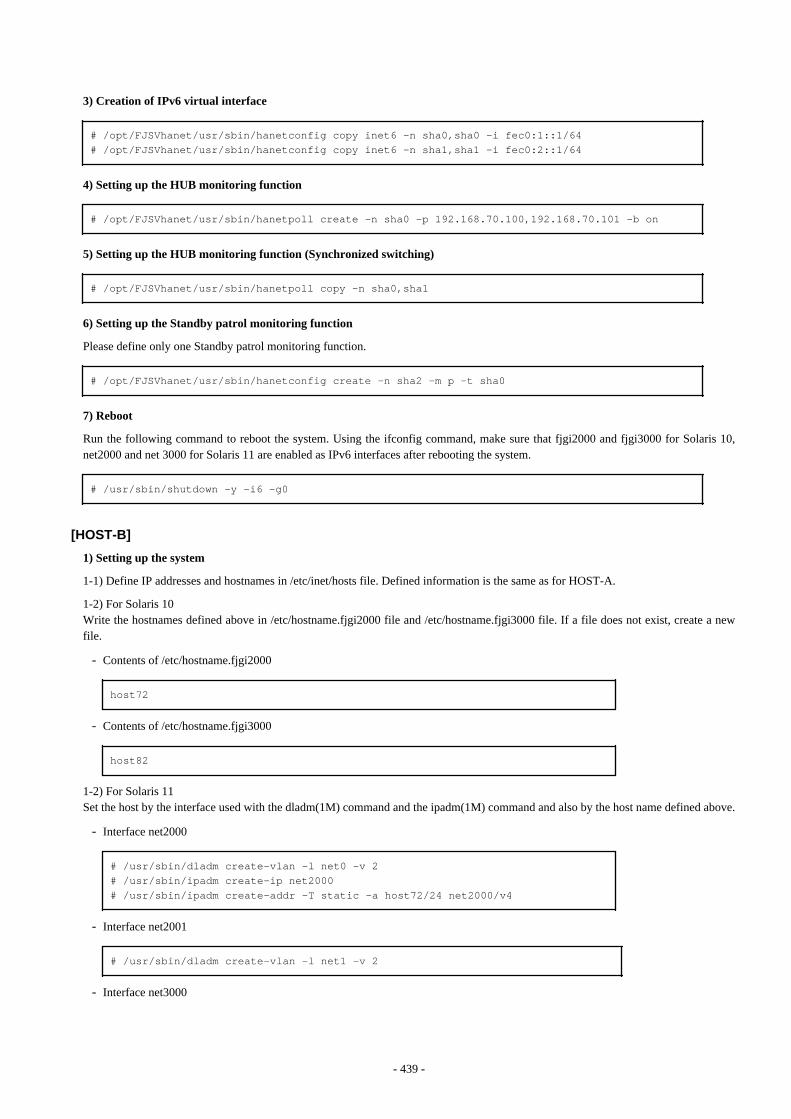
3) Creation of IPv6 virtual interface
# /opt/FJSVhanet/usr/sbin/hanetconfig copy inet6 -n sha0,sha0 -i fec0:1::1/64# /opt/FJSVhanet/usr/sbin/hanetconfig copy inet6 -n sha1,sha1 -i fec0:2::1/64
4) Setting up the HUB monitoring function
# /opt/FJSVhanet/usr/sbin/hanetpoll create -n sha0 -p 192.168.70.100,192.168.70.101 -b on
5) Setting up the HUB monitoring function (Synchronized switching)
# /opt/FJSVhanet/usr/sbin/hanetpoll copy -n sha0,sha1
6) Setting up the Standby patrol monitoring function
Please define only one Standby patrol monitoring function.
# /opt/FJSVhanet/usr/sbin/hanetconfig create -n sha2 -m p -t sha0
7) Reboot
Run the following command to reboot the system. Using the ifconfig command, make sure that fjgi2000 and fjgi3000 for Solaris 10,net2000 and net 3000 for Solaris 11 are enabled as IPv6 interfaces after rebooting the system.
# /usr/sbin/shutdown -y -i6 -g0
[HOST-B]
1) Setting up the system
1-1) Define IP addresses and hostnames in /etc/inet/hosts file. Defined information is the same as for HOST-A.
1-2) For Solaris 10Write the hostnames defined above in /etc/hostname.fjgi2000 file and /etc/hostname.fjgi3000 file. If a file does not exist, create a newfile.
- Contents of /etc/hostname.fjgi2000
host72
- Contents of /etc/hostname.fjgi3000
host82
1-2) For Solaris 11Set the host by the interface used with the dladm(1M) command and the ipadm(1M) command and also by the host name defined above.
- Interface net2000
# /usr/sbin/dladm create-vlan -l net0 -v 2# /usr/sbin/ipadm create-ip net2000# /usr/sbin/ipadm create-addr -T static -a host72/24 net2000/v4
- Interface net2001
# /usr/sbin/dladm create-vlan -l net1 -v 2
- Interface net3000
- 439 -

# /usr/sbin/dladm create-vlan -l net0 -v 3# /usr/sbin/ipadm create-ip net3000# /usr/sbin/ipadm create-addr -T static -a host82/24 net3000/v4
- Interface net3001
# /usr/sbin/dladm create-vlan -l net1 -v 3
1-3) Define the subnet mask in /etc/inet/netmasks file. Defined content is same as HOST-A.
1-4) For Solaris 10Create /etc/hostname6.fjgi2000 and /etc/hostname6.fjgi3000 file as an empty file.
1-4) For Solaris 11Set the interface to be used by using the ipadm(1M) command.
- Interface net2000
# /usr/sbin/ipadm create-addr -T addrconf net2000/v6
- Interface net3000
# /usr/sbin/ipadm create-addr -T addrconf net3000/v6
1-5) Define IP addresses and hostnames in /etc/inet/ipnodes file. Defined content is same as HOST-A.
2) Creation of IPv4 virtual interface
2-1) For Solaris 10
# /opt/FJSVhanet/usr/sbin/hanetconfig create -n sha0 -m d -i 192.168.70.2 -e 192.168.70.4 -t fjgi2000,fjgi2001# /opt/FJSVhanet/usr/sbin/hanetconfig create -n sha1 -m d -i 192.168.80.2 -e 192.168.80.4 -t fjgi3000,fjgi3001
2-1) For Solaris 11
# /opt/FJSVhanet/usr/sbin/hanetconfig create -n sha0 -m d -i 192.168.70.2 -e 192.168.70.4 -t net2000,net2001# /opt/FJSVhanet/usr/sbin/hanetconfig create -n sha1 -m d -i 192.168.80.2 -e 192.168.80.4 -t net3000,net3001
Note
Ensure that the physical IP address specified using option '-e' is the same IP address configured in /etc/hostname.fjgi2000, in /etc/hostname.fjgi3000, or with the ipadm(1M) command.
3) Creation of IPv6 virtual interface
# /opt/FJSVhanet/usr/sbin/hanetconfig copy inet6 -n sha0,sha0 -i fec0:1::2/64# /opt/FJSVhanet/usr/sbin/hanetconfig copy inet6 -n sha1,sha1 -i fec0:2::2/64
4) Setting up the HUB monitoring function
# /opt/FJSVhanet/usr/sbin/hanetpoll create -n sha0 -p 192.168.70.100,192.168.70.101 -b on
5) Setting up the HUB monitoring function (Synchronized switching)
- 440 -
# /opt/FJSVhanet/usr/sbin/hanetpoll copy -n sha0,sha1
6) Setting up the Standby patrol monitoring function
Please define only one Standby patrol monitoring function.
# /opt/FJSVhanet/usr/sbin/hanetconfig create -n sha2 -m p -t sha0
7) Reboot
Run the following command to reboot the system. Using the ifconfig command, make sure that fjgi2000 and fjgi3000 for Solaris 10,net2000 and net 3000 for Solaris 11 are enabled as IPv6 interfaces after rebooting the system.
# /usr/sbin/shutdown -y -i6 -g0
B.6.4 Configuring virtual interfaces with tagged VLAN (asynchronizedswitching)
This section describes an example configuration procedure of the network shown in the diagram below.
The xx, yy in the figure below are assigned automatically by the automatic address configuration.
If the Standby patrol monitoring function is not used, omit 5) in the procedure for setting up on each host.
- 441 -
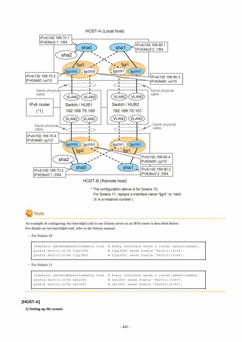
Note
An example of configuring /etc/inet/ndpd.conf to use Solaris server as an IPv6 router is described below:For details on /etc/inet/ndpd.conf, refer to the Solaris manual.
- For Solaris 10
ifdefault AdvSendAdvertisements true # Every interface sends a router advertisement.prefix fec0:1::0/64 fjgi2000 # fjgi2000 sends Prefix "fec0:1::0/64".prefix fec0:2::0/64 fjgi3001 # fjgi3001 sends Prefix "fec0:2::0/64".
- For Solaris 11
ifdefault AdvSendAdvertisements true # Every interface sends a router advertisement.prefix fec0:1::0/64 net2000 # net2000 sends Prefix "fec0:1::0/64".prefix fec0:2::0/64 net3001 # net3001 sends Prefix "fec0:2::0/64".
[HOST-A]
1) Setting up the system
- 442 -

1-1) Define IP addresses and hostnames in /etc/inet/hosts file.
192.168.70.1 hosta # HOST-A Virtual IP192.168.70.3 host71 # HOST-A Physical IP (Tagged VLAN interface)192.168.80.1 hostb # HOST-A Virtual IP192.168.80.3 host81 # HOST-A Physical IP (Tagged VLAN interface)192.168.70.2 hostc # HOST-B Virtual IP192.168.70.4 host72 # HOST-B Physical IP (Tagged VLAN interface)192.168.80.2 hostd # HOST-B Virtual IP192.168.80.4 host82 # HOST-B Physical IP (Tagged VLAN interface)192.168.70.100 swhub1 # Switch/HUB1 IP192.168.80.100 swhub2 # Switch/HUB2 IP
1-2) For Solaris 10Write the hostnames defined above in /etc/hostname.fjgi2000 file and /etc/hostname.fjgi3001 file. If a file does not exist, create a newfile.
- Contents of /etc/hostname.fjgi2000
host71
- Contents of /etc/hostname.fjgi3001
host81
1-2) For Solaris 11Set the host by the interface used with the dladm(1M) command and the ipadm(1M) command and also by the host name defined above.
- Interface net2000
# /usr/sbin/dladm create-vlan -l net0 -v 2# /usr/sbin/ipadm create-ip net2000# /usr/sbin/ipadm create-addr -T static -a host71/24 net2000/v4
- Interface net2001
# /usr/sbin/dladm create-vlan -l net1 -v 2
- Interface net3000
# /usr/sbin/dladm create-vlan -l net0 -v 3
- Interface net3001
# /usr/sbin/dladm create-vlan -l net1 -v 3# /usr/sbin/ipadm create-ip net3001# /usr/sbin/ipadm create-addr -T static -a host81/24 net3001/v4
1-3) Define the subnet mask in /etc/inet/netmasks file.
192.168.70.0 255.255.255.0192.168.80.0 255.255.255.0
1-4) For Solaris 10Create /etc/hostname6.fjgi12000 and /etc/hostname6.fjgi3001 file as an empty file.
1-4) For Solaris 11Set the interface to be used by using the ipadm(1M) command.
- 443 -
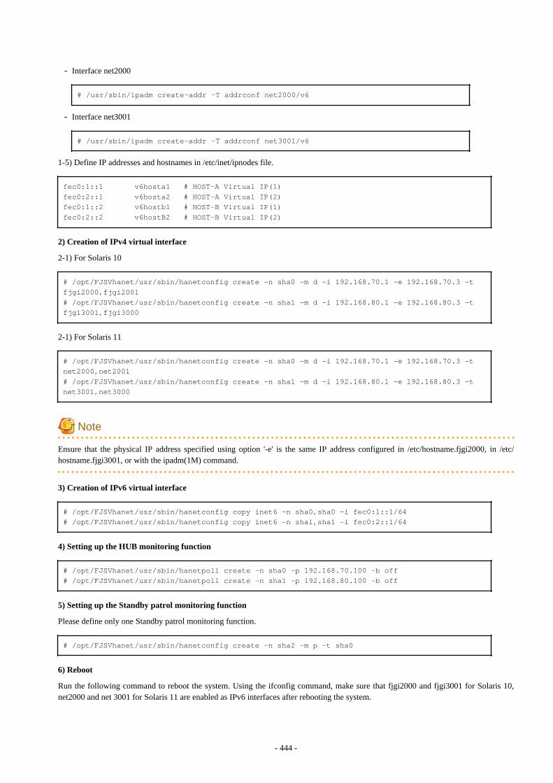
- Interface net2000
# /usr/sbin/ipadm create-addr -T addrconf net2000/v6
- Interface net3001
# /usr/sbin/ipadm create-addr -T addrconf net3001/v6
1-5) Define IP addresses and hostnames in /etc/inet/ipnodes file.
fec0:1::1 v6hosta1 # HOST-A Virtual IP(1)fec0:2::1 v6hosta2 # HOST-A Virtual IP(2)fec0:1::2 v6hostb1 # HOST-B Virtual IP(1)fec0:2::2 v6hostB2 # HOST-B Virtual IP(2)
2) Creation of IPv4 virtual interface
2-1) For Solaris 10
# /opt/FJSVhanet/usr/sbin/hanetconfig create -n sha0 -m d -i 192.168.70.1 -e 192.168.70.3 -t fjgi2000,fjgi2001# /opt/FJSVhanet/usr/sbin/hanetconfig create -n sha1 -m d -i 192.168.80.1 -e 192.168.80.3 -t fjgi3001,fjgi3000
2-1) For Solaris 11
# /opt/FJSVhanet/usr/sbin/hanetconfig create -n sha0 -m d -i 192.168.70.1 -e 192.168.70.3 -t net2000,net2001# /opt/FJSVhanet/usr/sbin/hanetconfig create -n sha1 -m d -i 192.168.80.1 -e 192.168.80.3 -t net3001,net3000
Note
Ensure that the physical IP address specified using option '-e' is the same IP address configured in /etc/hostname.fjgi2000, in /etc/hostname.fjgi3001, or with the ipadm(1M) command.
3) Creation of IPv6 virtual interface
# /opt/FJSVhanet/usr/sbin/hanetconfig copy inet6 -n sha0,sha0 -i fec0:1::1/64# /opt/FJSVhanet/usr/sbin/hanetconfig copy inet6 -n sha1,sha1 -i fec0:2::1/64
4) Setting up the HUB monitoring function
# /opt/FJSVhanet/usr/sbin/hanetpoll create -n sha0 -p 192.168.70.100 -b off# /opt/FJSVhanet/usr/sbin/hanetpoll create -n sha1 -p 192.168.80.100 -b off
5) Setting up the Standby patrol monitoring function
Please define only one Standby patrol monitoring function.
# /opt/FJSVhanet/usr/sbin/hanetconfig create -n sha2 -m p -t sha0
6) Reboot
Run the following command to reboot the system. Using the ifconfig command, make sure that fjgi2000 and fjgi3001 for Solaris 10,net2000 and net 3001 for Solaris 11 are enabled as IPv6 interfaces after rebooting the system.
- 444 -
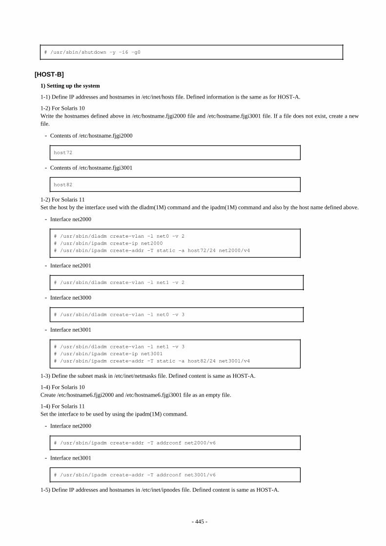
# /usr/sbin/shutdown -y -i6 -g0
[HOST-B]
1) Setting up the system
1-1) Define IP addresses and hostnames in /etc/inet/hosts file. Defined information is the same as for HOST-A.
1-2) For Solaris 10Write the hostnames defined above in /etc/hostname.fjgi2000 file and /etc/hostname.fjgi3001 file. If a file does not exist, create a newfile.
- Contents of /etc/hostname.fjgi2000
host72
- Contents of /etc/hostname.fjgi3001
host82
1-2) For Solaris 11Set the host by the interface used with the dladm(1M) command and the ipadm(1M) command and also by the host name defined above.
- Interface net2000
# /usr/sbin/dladm create-vlan -l net0 -v 2# /usr/sbin/ipadm create-ip net2000# /usr/sbin/ipadm create-addr -T static -a host72/24 net2000/v4
- Interface net2001
# /usr/sbin/dladm create-vlan -l net1 -v 2
- Interface net3000
# /usr/sbin/dladm create-vlan -l net0 -v 3
- Interface net3001
# /usr/sbin/dladm create-vlan -l net1 -v 3# /usr/sbin/ipadm create-ip net3001# /usr/sbin/ipadm create-addr -T static -a host82/24 net3001/v4
1-3) Define the subnet mask in /etc/inet/netmasks file. Defined content is same as HOST-A.
1-4) For Solaris 10Create /etc/hostname6.fjgi2000 and /etc/hostname6.fjgi3001 file as an empty file.
1-4) For Solaris 11Set the interface to be used by using the ipadm(1M) command.
- Interface net2000
# /usr/sbin/ipadm create-addr -T addrconf net2000/v6
- Interface net3001
# /usr/sbin/ipadm create-addr -T addrconf net3001/v6
1-5) Define IP addresses and hostnames in /etc/inet/ipnodes file. Defined content is same as HOST-A.
- 445 -

2) Creation of IPv4 virtual interface
2-1) For Solaris 10
# /opt/FJSVhanet/usr/sbin/hanetconfig create -n sha0 -m d -i 192.168.70.2 -e 192.168.70.4 -t fjgi2000,fjgi2001# /opt/FJSVhanet/usr/sbin/hanetconfig create -n sha1 -m d -i 192.168.80.2 -e 192.168.80.4 -t fjgi3001,fjgi3000
2-1) For Solaris 11
# /opt/FJSVhanet/usr/sbin/hanetconfig create -n sha0 -m d -i 192.168.70.2 -e 192.168.70.4 -t net2000,net2001# /opt/FJSVhanet/usr/sbin/hanetconfig create -n sha1 -m d -i 192.168.80.2 -e 192.168.80.4 -t net3001,net3000
Note
Ensure that the physical IP address specified using option '-e' is the same IP address configured in /etc/hostname.fjgi2000, in /etc/hostname.fjgi3001, or with the ipadm(1M) command.
3) Creation of IPv6 virtual interface
# /opt/FJSVhanet/usr/sbin/hanetconfig copy inet6 -n sha0,sha0 -i fec0:1::2/64# /opt/FJSVhanet/usr/sbin/hanetconfig copy inet6 -n sha1,sha1 -i fec0:2::2/64
4) Setting up the HUB monitoring function
# /opt/FJSVhanet/usr/sbin/hanetpoll create -n sha0 -p 192.168.70.100 -b off# /opt/FJSVhanet/usr/sbin/hanetpoll create -n sha1 -p 192.168.80.100 -b off
5) Setting up the Standby patrol monitoring function
Please define only one Standby patrol monitoring function.
# /opt/FJSVhanet/usr/sbin/hanetconfig create -n sha2 -m p -t sha0
6) Reboot
Run the following command to reboot the system. Using the ifconfig command, make sure that fjgi2000 and fjgi3001 for Solaris 10,net2000 and net 3001 for Solaris 11 are enabled as IPv4/IPv6 interfaces after rebooting the system.
# /usr/sbin/shutdown -y -i6 -g0
B.6.5 Example of the Cluster system (1:1 Standby) without NIC sharingThis section describes an example configuration procedure of the network shown in the diagram below.
The xx, yy in the figure below are assigned automatically by the automatic address configuration.
For configuring the cluster system, refer to the Cluster system manual.In this section, description of private LAN is omitted. The dotted line indicates that the interface is inactive.
If the Standby patrol monitoring function is not used, omit 6) and 9) in the procedure for setting up on each host.
- 446 -

Note
When using IPv6 address as a takeover virtual interface, it may take around 30 seconds to recover the communication after switching thenode. In order to hold a communication instantly, start IPv6 routing daemon beforehand on both operating and standby nodes. For detailson this issue, refer to "F.2 Troubleshooting".
Note
An example of configuring /etc/inet/ndpd.conf to use Solaris server as an IPv6 router is described below:For details on /etc/inet/ndpd.conf, refer to the Solaris manual.
- For Solaris 10
ifdefault AdvSendAdvertisements true # Every interface sends a router advertisement.prefix fec0:1::0/64 fjgi0 # fjgi0 sends Prefix "fec0:1::0/64".
- For Solaris 11
ifdefault AdvSendAdvertisements true # Every interface sends a router advertisement.prefix fec0:1::0/64 net0 # net0 sends Prefix "fec0:1::0/64".
[HOST-A]
1) Setting up the system
1-1) Define IP addresses and hostnames in /etc/inet/hosts file.
192.168.70.1 hosta # HOST-A/B Takeover virtual IP192.168.70.2 host11 # HOST-A Physical IP192.168.70.3 host21 # HOST-B Physical IP
- 447 -
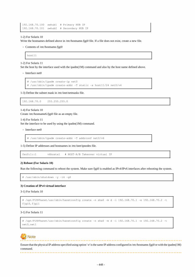
192.168.70.100 swhub1 # Primary HUB IP192.168.70.101 swhub2 # Secondary HUB IP
1-2) For Solaris 10Write the hostnames defined above in /etc/hostname.fjgi0 file. If a file does not exist, create a new file.
- Contents of /etc/hostname.fjgi0
host11
1-2) For Solaris 11Set the host by the interface used with the ipadm(1M) command and also by the host name defined above.
- Interface net0
# /usr/sbin/ipadm create-ip net0# /usr/sbin/ipadm create-addr -T static -a host11/24 net0/v4
1-3) Define the subnet mask in /etc/inet/netmasks file.
192.168.70.0 255.255.255.0
1-4) For Solaris 10Create /etc/hostname6.fjgi0 file as an empty file.
1-4) For Solaris 11Set the interface to be used by using the ipadm(1M) command.
- Interface net0
# /usr/sbin/ipadm create-addr -T addrconf net0/v6
1-5) Define IP addresses and hostnames in /etc/inet/ipnodes file.
fec0:1::1 v6hosta1 # HOST-A/B Takeover virtual IP
2) Reboot (For Solaris 10)
Run the following command to reboot the system. Make sure fjgi0 is enabled as IPv4/IPv6 interfaces after rebooting the system.
# /usr/sbin/shutdown -y -i6 -g0
3) Creation of IPv4 virtual interface
3-1) For Solaris 10
# /opt/FJSVhanet/usr/sbin/hanetconfig create -n sha0 -m d -i 192.168.70.1 -e 192.168.70.2 -t fjgi0,fjgi1
3-1) For Solaris 11
# /opt/FJSVhanet/usr/sbin/hanetconfig create -n sha0 -m d -i 192.168.70.1 -e 192.168.70.2 -t net0,net1
Note
Ensure that the physical IP address specified using option '-e' is the same IP address configured in /etc/hostname.fjgi0 or with the ipadm(1M)command.
- 448 -
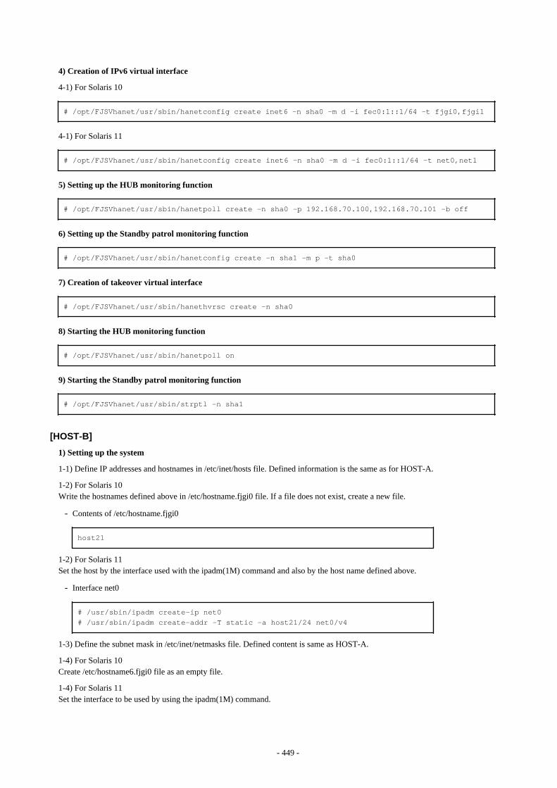
4) Creation of IPv6 virtual interface
4-1) For Solaris 10
# /opt/FJSVhanet/usr/sbin/hanetconfig create inet6 -n sha0 -m d -i fec0:1::1/64 -t fjgi0,fjgi1
4-1) For Solaris 11
# /opt/FJSVhanet/usr/sbin/hanetconfig create inet6 -n sha0 -m d -i fec0:1::1/64 -t net0,net1
5) Setting up the HUB monitoring function
# /opt/FJSVhanet/usr/sbin/hanetpoll create -n sha0 -p 192.168.70.100,192.168.70.101 -b off
6) Setting up the Standby patrol monitoring function
# /opt/FJSVhanet/usr/sbin/hanetconfig create -n sha1 -m p -t sha0
7) Creation of takeover virtual interface
# /opt/FJSVhanet/usr/sbin/hanethvrsc create -n sha0
8) Starting the HUB monitoring function
# /opt/FJSVhanet/usr/sbin/hanetpoll on
9) Starting the Standby patrol monitoring function
# /opt/FJSVhanet/usr/sbin/strptl -n sha1
[HOST-B]
1) Setting up the system
1-1) Define IP addresses and hostnames in /etc/inet/hosts file. Defined information is the same as for HOST-A.
1-2) For Solaris 10Write the hostnames defined above in /etc/hostname.fjgi0 file. If a file does not exist, create a new file.
- Contents of /etc/hostname.fjgi0
host21
1-2) For Solaris 11Set the host by the interface used with the ipadm(1M) command and also by the host name defined above.
- Interface net0
# /usr/sbin/ipadm create-ip net0# /usr/sbin/ipadm create-addr -T static -a host21/24 net0/v4
1-3) Define the subnet mask in /etc/inet/netmasks file. Defined content is same as HOST-A.
1-4) For Solaris 10Create /etc/hostname6.fjgi0 file as an empty file.
1-4) For Solaris 11Set the interface to be used by using the ipadm(1M) command.
- 449 -
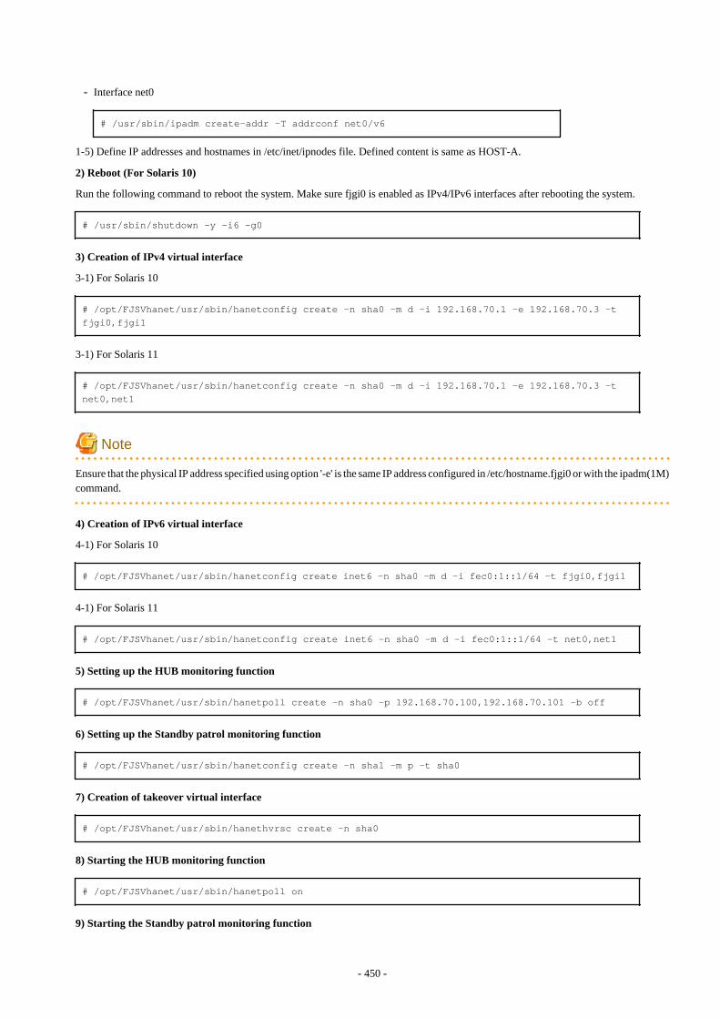
- Interface net0
# /usr/sbin/ipadm create-addr -T addrconf net0/v6
1-5) Define IP addresses and hostnames in /etc/inet/ipnodes file. Defined content is same as HOST-A.
2) Reboot (For Solaris 10)
Run the following command to reboot the system. Make sure fjgi0 is enabled as IPv4/IPv6 interfaces after rebooting the system.
# /usr/sbin/shutdown -y -i6 -g0
3) Creation of IPv4 virtual interface
3-1) For Solaris 10
# /opt/FJSVhanet/usr/sbin/hanetconfig create -n sha0 -m d -i 192.168.70.1 -e 192.168.70.3 -t fjgi0,fjgi1
3-1) For Solaris 11
# /opt/FJSVhanet/usr/sbin/hanetconfig create -n sha0 -m d -i 192.168.70.1 -e 192.168.70.3 -t net0,net1
Note
Ensure that the physical IP address specified using option '-e' is the same IP address configured in /etc/hostname.fjgi0 or with the ipadm(1M)command.
4) Creation of IPv6 virtual interface
4-1) For Solaris 10
# /opt/FJSVhanet/usr/sbin/hanetconfig create inet6 -n sha0 -m d -i fec0:1::1/64 -t fjgi0,fjgi1
4-1) For Solaris 11
# /opt/FJSVhanet/usr/sbin/hanetconfig create inet6 -n sha0 -m d -i fec0:1::1/64 -t net0,net1
5) Setting up the HUB monitoring function
# /opt/FJSVhanet/usr/sbin/hanetpoll create -n sha0 -p 192.168.70.100,192.168.70.101 -b off
6) Setting up the Standby patrol monitoring function
# /opt/FJSVhanet/usr/sbin/hanetconfig create -n sha1 -m p -t sha0
7) Creation of takeover virtual interface
# /opt/FJSVhanet/usr/sbin/hanethvrsc create -n sha0
8) Starting the HUB monitoring function
# /opt/FJSVhanet/usr/sbin/hanetpoll on
9) Starting the Standby patrol monitoring function
- 450 -
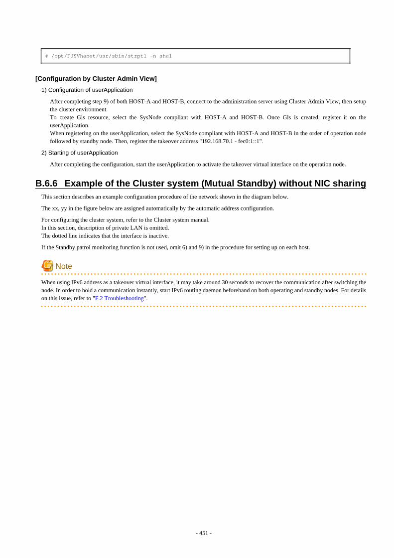
# /opt/FJSVhanet/usr/sbin/strptl -n sha1
[Configuration by Cluster Admin View]
1) Configuration of userApplication
After completing step 9) of both HOST-A and HOST-B, connect to the administration server using Cluster Admin View, then setupthe cluster environment.To create Gls resource, select the SysNode compliant with HOST-A and HOST-B. Once Gls is created, register it on theuserApplication.When registering on the userApplication, select the SysNode compliant with HOST-A and HOST-B in the order of operation nodefollowed by standby node. Then, register the takeover address "192.168.70.1 - fec0:1::1".
2) Starting of userApplication
After completing the configuration, start the userApplication to activate the takeover virtual interface on the operation node.
B.6.6 Example of the Cluster system (Mutual Standby) without NIC sharingThis section describes an example configuration procedure of the network shown in the diagram below.
The xx, yy in the figure below are assigned automatically by the automatic address configuration.
For configuring the cluster system, refer to the Cluster system manual.In this section, description of private LAN is omitted. The dotted line indicates that the interface is inactive.
If the Standby patrol monitoring function is not used, omit 6) and 9) in the procedure for setting up on each host.
Note
When using IPv6 address as a takeover virtual interface, it may take around 30 seconds to recover the communication after switching thenode. In order to hold a communication instantly, start IPv6 routing daemon beforehand on both operating and standby nodes. For detailson this issue, refer to "F.2 Troubleshooting".
- 451 -
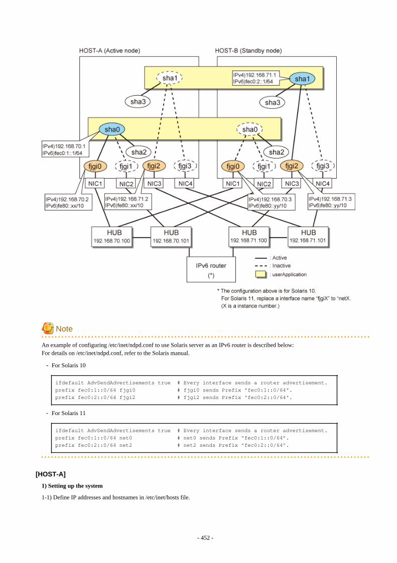
Note
An example of configuring /etc/inet/ndpd.conf to use Solaris server as an IPv6 router is described below:For details on /etc/inet/ndpd.conf, refer to the Solaris manual.
- For Solaris 10
ifdefault AdvSendAdvertisements true # Every interface sends a router advertisement.prefix fec0:1::0/64 fjgi0 # fjgi0 sends Prefix "fec0:1::0/64".prefix fec0:2::0/64 fjgi2 # fjgi2 sends Prefix "fec0:2::0/64".
- For Solaris 11
ifdefault AdvSendAdvertisements true # Every interface sends a router advertisement.prefix fec0:1::0/64 net0 # net0 sends Prefix "fec0:1::0/64".prefix fec0:2::0/64 net2 # net2 sends Prefix "fec0:2::0/64".
[HOST-A]
1) Setting up the system
1-1) Define IP addresses and hostnames in /etc/inet/hosts file.
- 452 -

192.168.70.1 hosta # HOST-A/B Virtual IP (Takeover IP1)192.168.70.2 host11 # HOST-A Physical IP (1)192.168.70.3 host21 # HOST-B Physical IP (1)192.168.71.1 hostb # HOST-A/B Virtual IP (Takeover IP2)192.168.71.2 host12 # HOST-A Physical IP (2)192.168.71.3 host22 # HOST-B Physical IP (2)192.168.70.100 swhub1 # Primary HUB IP (1)192.168.70.101 swhub2 # Secondary HUB IP (1)192.168.71.100 swhub3 # Primary HUB IP (2)192.168.71.101 swhub4 # Secondary HUB IP (2)
1-2) For Solaris 10Write the hostnames defined above in /etc/hostname.fjgi0 file and /etc/hostname.fjgi2 file. If a file does not exist, create a new file.
- Contents of /etc/hostname.fjgi0
host11
- Contents of /etc/hostname.fjgi2
host12
1-2) For Solaris 11Set the host by the interface used with the ipadm(1M) command and also by the host name defined above.
- Interface net0
# /usr/sbin/ipadm create-ip net0# /usr/sbin/ipadm create-addr -T static -a host11/24 net0/v4
- Interface net2
# /usr/sbin/ipadm create-ip net2# /usr/sbin/ipadm create-addr -T static -a host12/24 net2/v4
1-3) Define the subnet mask in /etc/inet/netmasks file.
192.168.70.0 255.255.255.0192.168.71.0 255.255.255.0
1-4) For Solaris 10Create /etc/hostname6.fjgi0 and /etc/hostname6.fjgi2 files as an empty file.
1-4) For Solaris 11Set the interface to be used by using the ipadm(1M) command.
- Interface net0
# /usr/sbin/ipadm create-addr -T addrconf net0/v6
- Interface net2
# /usr/sbin/ipadm create-addr -T addrconf net2/v6
1-5) Define IP addresses and hostnames in /etc/inet/ipnodes file.
fec0:1::1 v6hosta # HOST-A/B Takeover virtual IP (1)fec0:2::1 v6hostb # HOST-A/B Takeover virtual IP (2)
- 453 -
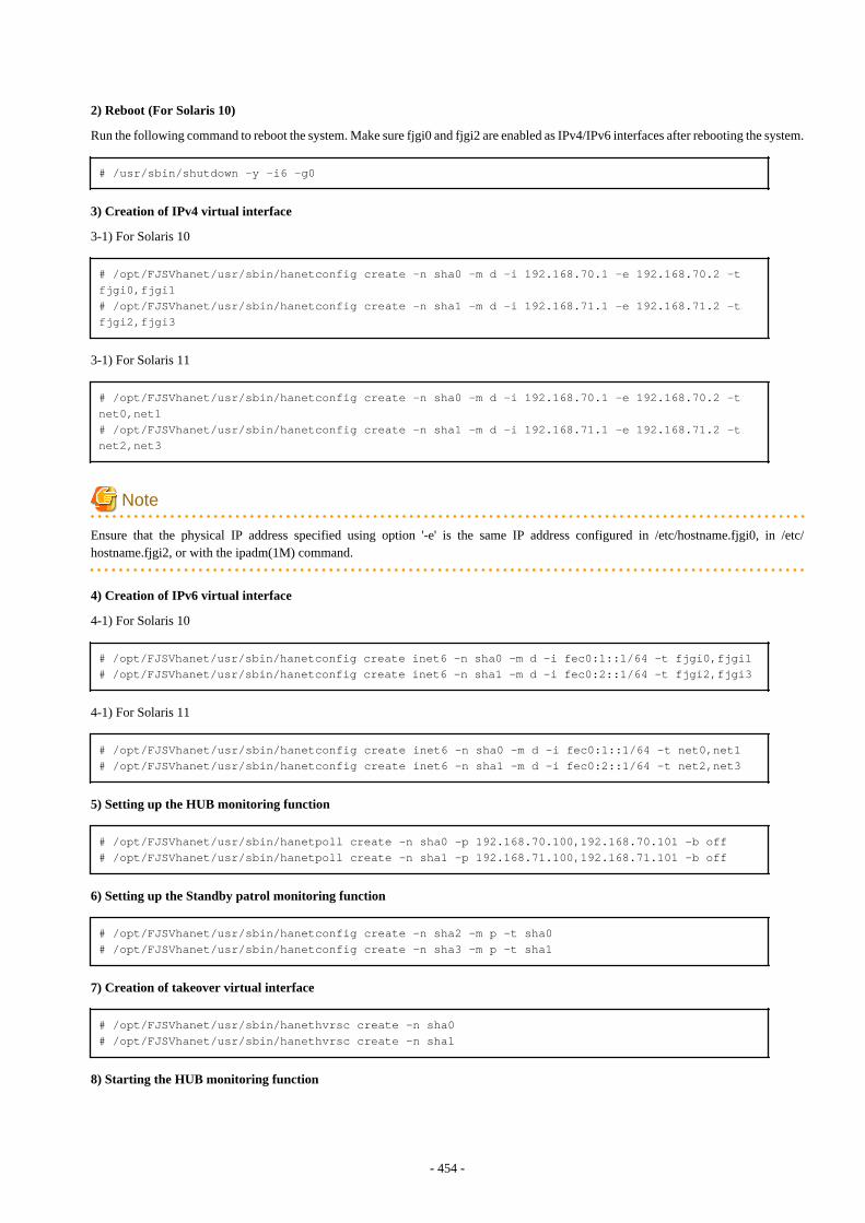
2) Reboot (For Solaris 10)
Run the following command to reboot the system. Make sure fjgi0 and fjgi2 are enabled as IPv4/IPv6 interfaces after rebooting the system.
# /usr/sbin/shutdown -y -i6 -g0
3) Creation of IPv4 virtual interface
3-1) For Solaris 10
# /opt/FJSVhanet/usr/sbin/hanetconfig create -n sha0 -m d -i 192.168.70.1 -e 192.168.70.2 -t fjgi0,fjgi1# /opt/FJSVhanet/usr/sbin/hanetconfig create -n sha1 -m d -i 192.168.71.1 -e 192.168.71.2 -t fjgi2,fjgi3
3-1) For Solaris 11
# /opt/FJSVhanet/usr/sbin/hanetconfig create -n sha0 -m d -i 192.168.70.1 -e 192.168.70.2 -t net0,net1# /opt/FJSVhanet/usr/sbin/hanetconfig create -n sha1 -m d -i 192.168.71.1 -e 192.168.71.2 -t net2,net3
Note
Ensure that the physical IP address specified using option '-e' is the same IP address configured in /etc/hostname.fjgi0, in /etc/hostname.fjgi2, or with the ipadm(1M) command.
4) Creation of IPv6 virtual interface
4-1) For Solaris 10
# /opt/FJSVhanet/usr/sbin/hanetconfig create inet6 -n sha0 -m d -i fec0:1::1/64 -t fjgi0,fjgi1# /opt/FJSVhanet/usr/sbin/hanetconfig create inet6 -n sha1 -m d -i fec0:2::1/64 -t fjgi2,fjgi3
4-1) For Solaris 11
# /opt/FJSVhanet/usr/sbin/hanetconfig create inet6 -n sha0 -m d -i fec0:1::1/64 -t net0,net1# /opt/FJSVhanet/usr/sbin/hanetconfig create inet6 -n sha1 -m d -i fec0:2::1/64 -t net2,net3
5) Setting up the HUB monitoring function
# /opt/FJSVhanet/usr/sbin/hanetpoll create -n sha0 -p 192.168.70.100,192.168.70.101 -b off# /opt/FJSVhanet/usr/sbin/hanetpoll create -n sha1 -p 192.168.71.100,192.168.71.101 -b off
6) Setting up the Standby patrol monitoring function
# /opt/FJSVhanet/usr/sbin/hanetconfig create -n sha2 -m p -t sha0# /opt/FJSVhanet/usr/sbin/hanetconfig create -n sha3 -m p -t sha1
7) Creation of takeover virtual interface
# /opt/FJSVhanet/usr/sbin/hanethvrsc create -n sha0# /opt/FJSVhanet/usr/sbin/hanethvrsc create -n sha1
8) Starting the HUB monitoring function
- 454 -

# /opt/FJSVhanet/usr/sbin/hanetpoll on
9) Starting the Standby patrol monitoring function
# /opt/FJSVhanet/usr/sbin/strptl -n sha2# /opt/FJSVhanet/usr/sbin/strptl -n sha3
[HOST-B]
1) Setting up the system
1-1) Define IP addresses and hostnames in /etc/inet/hosts file. Defined information is the same as for HOST-A.
1-2) For Solaris 10Write the hostnames defined above in /etc/hostname.fjgi0 file and /etc/hostname.fjgi2 file. If a file does not exist, create a new file.
- Contents of /etc/hostname.fjgi0
host21
- Contents of /etc/hostname.fjgi2
host22
1-2) For Solaris 11Set the host by the interface used with the ipadm(1M) command and also by the host name defined above.
- Interface net0
# /usr/sbin/ipadm create-ip net0# /usr/sbin/ipadm create-addr -T static -a host21/24 net0/v4
- Interface net2
# /usr/sbin/ipadm create-ip net2# /usr/sbin/ipadm create-addr -T static -a host22/24 net2/v4
1-3) Define the subnet mask in /etc/inet/netmasks file. Defined content is same as HOST-A.
1-4) For Solaris 10Create /etc/hostname6.fjgi0 and /etc/hostname6.fjgi2 files as an empty file.
1-4) For Solaris 11Set the interface to be used by using the ipadm(1M) command.
- Interface net0
# /usr/sbin/ipadm create-addr -T addrconf net0/v6
- Interface net2
# /usr/sbin/ipadm create-addr -T addrconf net2/v6
1-5) Define IP addresses and hostnames in /etc/inet/ipnodes file. Defined content is same as HOST-A.
2) Reboot (For Solaris 10)
Run the following command to reboot the system. Make sure fjgi0 and fjgi2 are enabled as IPv4/IPv6 interfaces after rebooting the system.
# /usr/sbin/shutdown -y -i6 -g0
- 455 -
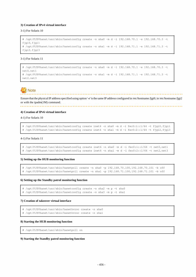
3) Creation of IPv4 virtual interface
3-1) For Solaris 10
# /opt/FJSVhanet/usr/sbin/hanetconfig create -n sha0 -m d -i 192.168.70.1 -e 192.168.70.3 -t fjgi0,fjgi1# /opt/FJSVhanet/usr/sbin/hanetconfig create -n sha1 -m d -i 192.168.71.1 -e 192.168.71.3 -t fjgi2,fjgi3
3-1) For Solaris 11
# /opt/FJSVhanet/usr/sbin/hanetconfig create -n sha0 -m d -i 192.168.70.1 -e 192.168.70.3 -t net0,net1# /opt/FJSVhanet/usr/sbin/hanetconfig create -n sha1 -m d -i 192.168.71.1 -e 192.168.71.3 -t net2,net3
Note
Ensure that the physical IP address specified using option '-e' is the same IP address configured in /etc/hostname.fjgi0, in /etc/hostname.fjgi2or with the ipadm(1M) command.
4) Creation of IPv6 virtual interface
4-1) For Solaris 10
# /opt/FJSVhanet/usr/sbin/hanetconfig create inet6 -n sha0 -m d -i fec0:1::1/64 -t fjgi0,fjgi1# /opt/FJSVhanet/usr/sbin/hanetconfig create inet6 -n sha1 -m d -i fec0:2::1/64 -t fjgi2,fjgi3
4-1) For Solaris 11
# /opt/FJSVhanet/usr/sbin/hanetconfig create inet6 -n sha0 -m d -i fec0:1::1/64 -t net0,net1# /opt/FJSVhanet/usr/sbin/hanetconfig create inet6 -n sha1 -m d -i fec0:2::1/64 -t net2,net3
5) Setting up the HUB monitoring function
# /opt/FJSVhanet/usr/sbin/hanetpoll create -n sha0 -p 192.168.70.100,192.168.70.101 -b off# /opt/FJSVhanet/usr/sbin/hanetpoll create -n sha1 -p 192.168.71.100,192.168.71.101 -b off
6) Setting up the Standby patrol monitoring function
# /opt/FJSVhanet/usr/sbin/hanetconfig create -n sha2 -m p -t sha0# /opt/FJSVhanet/usr/sbin/hanetconfig create -n sha3 -m p -t sha1
7) Creation of takeover virtual interface
# /opt/FJSVhanet/usr/sbin/hanethvrsc create -n sha0# /opt/FJSVhanet/usr/sbin/hanethvrsc create -n sha1
8) Starting the HUB monitoring function
# /opt/FJSVhanet/usr/sbin/hanetpoll on
9) Starting the Standby patrol monitoring function
- 456 -
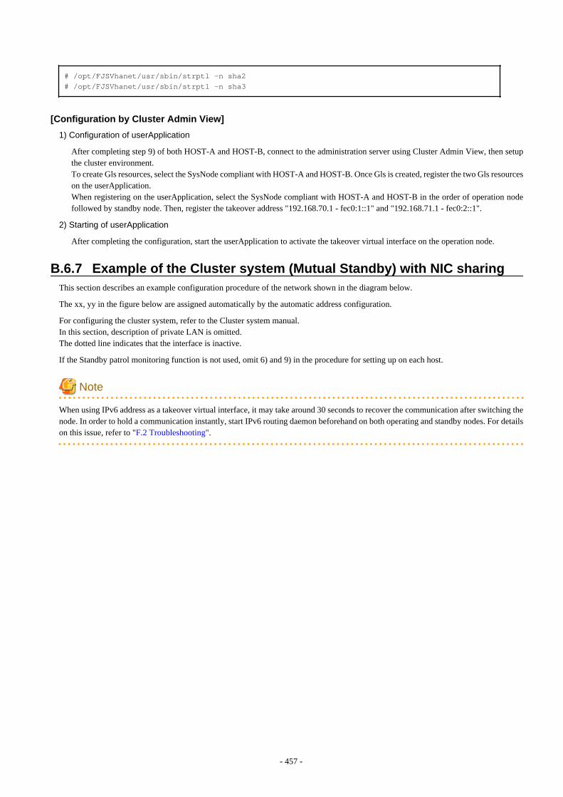
# /opt/FJSVhanet/usr/sbin/strptl -n sha2# /opt/FJSVhanet/usr/sbin/strptl -n sha3
[Configuration by Cluster Admin View]
1) Configuration of userApplication
After completing step 9) of both HOST-A and HOST-B, connect to the administration server using Cluster Admin View, then setupthe cluster environment.To create Gls resources, select the SysNode compliant with HOST-A and HOST-B. Once Gls is created, register the two Gls resourceson the userApplication.When registering on the userApplication, select the SysNode compliant with HOST-A and HOST-B in the order of operation nodefollowed by standby node. Then, register the takeover address "192.168.70.1 - fec0:1::1" and "192.168.71.1 - fec0:2::1".
2) Starting of userApplication
After completing the configuration, start the userApplication to activate the takeover virtual interface on the operation node.
B.6.7 Example of the Cluster system (Mutual Standby) with NIC sharingThis section describes an example configuration procedure of the network shown in the diagram below.
The xx, yy in the figure below are assigned automatically by the automatic address configuration.
For configuring the cluster system, refer to the Cluster system manual.In this section, description of private LAN is omitted. The dotted line indicates that the interface is inactive.
If the Standby patrol monitoring function is not used, omit 6) and 9) in the procedure for setting up on each host.
Note
When using IPv6 address as a takeover virtual interface, it may take around 30 seconds to recover the communication after switching thenode. In order to hold a communication instantly, start IPv6 routing daemon beforehand on both operating and standby nodes. For detailson this issue, refer to "F.2 Troubleshooting".
- 457 -
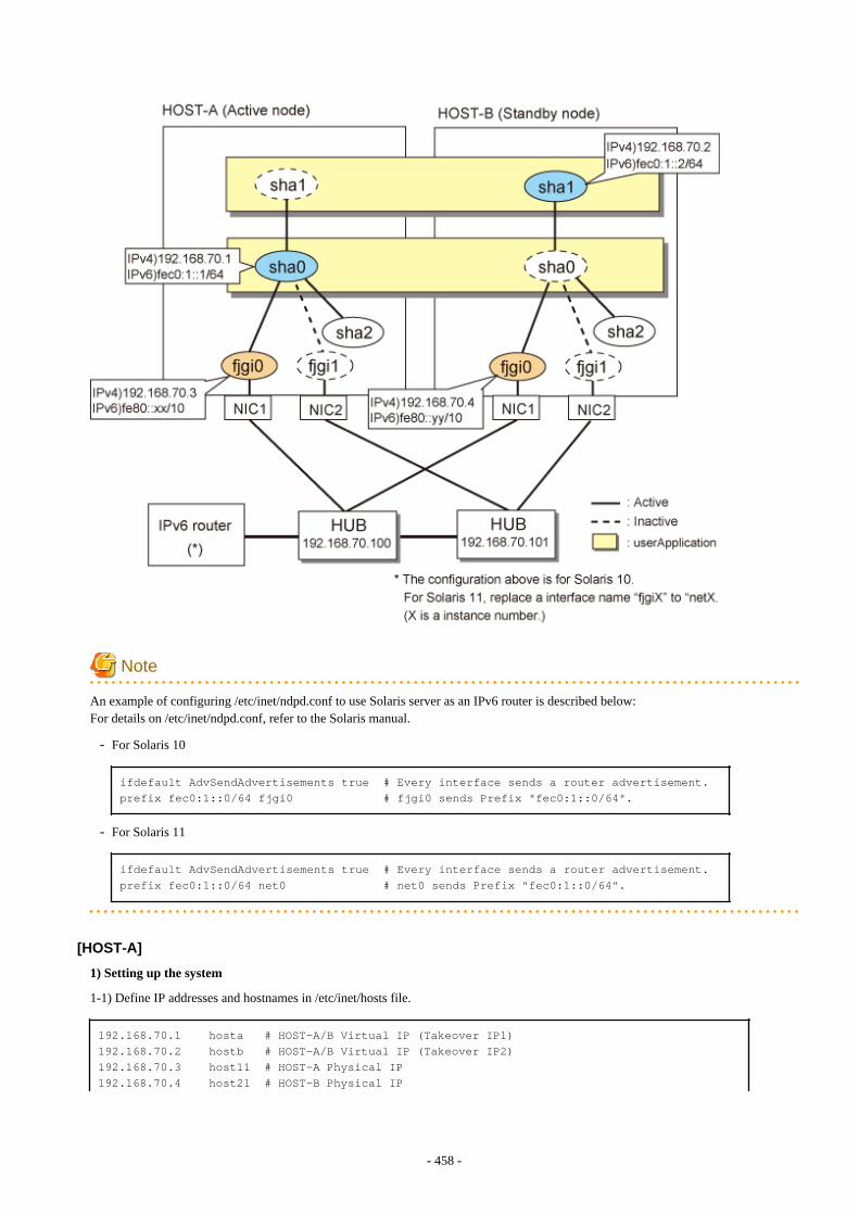
Note
An example of configuring /etc/inet/ndpd.conf to use Solaris server as an IPv6 router is described below:For details on /etc/inet/ndpd.conf, refer to the Solaris manual.
- For Solaris 10
ifdefault AdvSendAdvertisements true # Every interface sends a router advertisement.prefix fec0:1::0/64 fjgi0 # fjgi0 sends Prefix "fec0:1::0/64".
- For Solaris 11
ifdefault AdvSendAdvertisements true # Every interface sends a router advertisement.prefix fec0:1::0/64 net0 # net0 sends Prefix "fec0:1::0/64".
[HOST-A]
1) Setting up the system
1-1) Define IP addresses and hostnames in /etc/inet/hosts file.
192.168.70.1 hosta # HOST-A/B Virtual IP (Takeover IP1)192.168.70.2 hostb # HOST-A/B Virtual IP (Takeover IP2)192.168.70.3 host11 # HOST-A Physical IP192.168.70.4 host21 # HOST-B Physical IP
- 458 -
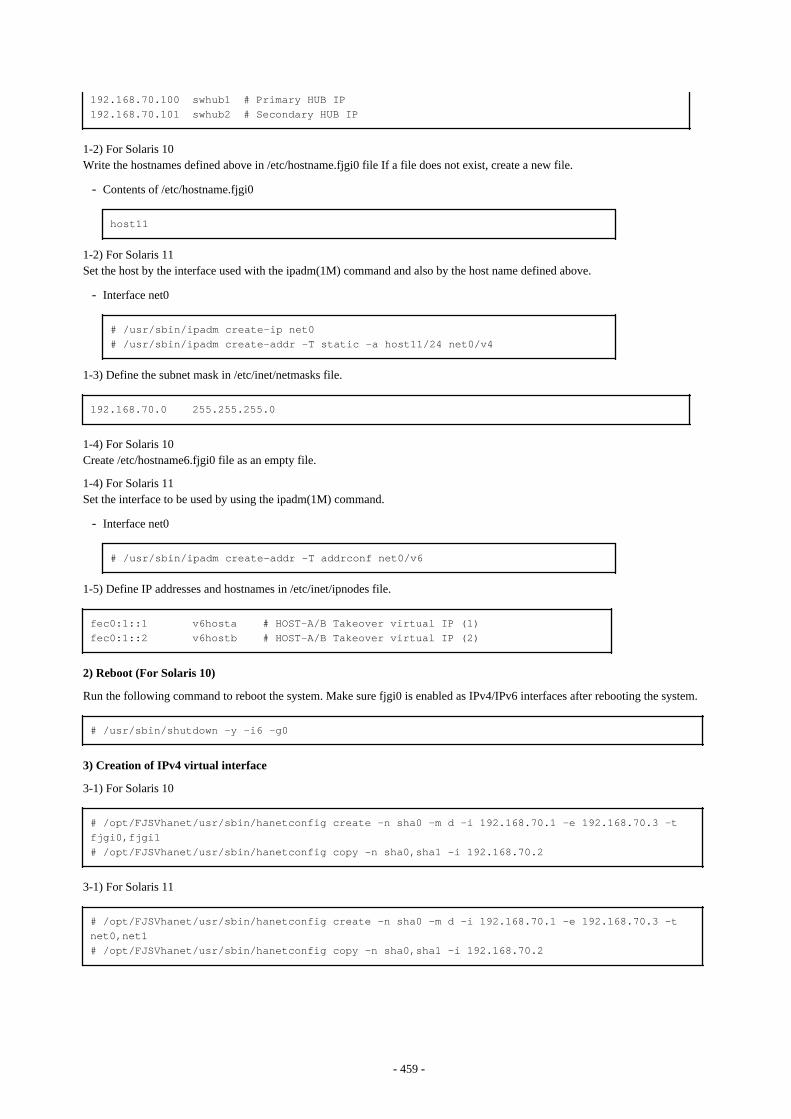
192.168.70.100 swhub1 # Primary HUB IP192.168.70.101 swhub2 # Secondary HUB IP
1-2) For Solaris 10Write the hostnames defined above in /etc/hostname.fjgi0 file If a file does not exist, create a new file.
- Contents of /etc/hostname.fjgi0
host11
1-2) For Solaris 11Set the host by the interface used with the ipadm(1M) command and also by the host name defined above.
- Interface net0
# /usr/sbin/ipadm create-ip net0# /usr/sbin/ipadm create-addr -T static -a host11/24 net0/v4
1-3) Define the subnet mask in /etc/inet/netmasks file.
192.168.70.0 255.255.255.0
1-4) For Solaris 10Create /etc/hostname6.fjgi0 file as an empty file.
1-4) For Solaris 11Set the interface to be used by using the ipadm(1M) command.
- Interface net0
# /usr/sbin/ipadm create-addr -T addrconf net0/v6
1-5) Define IP addresses and hostnames in /etc/inet/ipnodes file.
fec0:1::1 v6hosta # HOST-A/B Takeover virtual IP (1)fec0:1::2 v6hostb # HOST-A/B Takeover virtual IP (2)
2) Reboot (For Solaris 10)
Run the following command to reboot the system. Make sure fjgi0 is enabled as IPv4/IPv6 interfaces after rebooting the system.
# /usr/sbin/shutdown -y -i6 -g0
3) Creation of IPv4 virtual interface
3-1) For Solaris 10
# /opt/FJSVhanet/usr/sbin/hanetconfig create -n sha0 -m d -i 192.168.70.1 -e 192.168.70.3 -t fjgi0,fjgi1# /opt/FJSVhanet/usr/sbin/hanetconfig copy -n sha0,sha1 -i 192.168.70.2
3-1) For Solaris 11
# /opt/FJSVhanet/usr/sbin/hanetconfig create -n sha0 -m d -i 192.168.70.1 -e 192.168.70.3 -t net0,net1# /opt/FJSVhanet/usr/sbin/hanetconfig copy -n sha0,sha1 -i 192.168.70.2
- 459 -
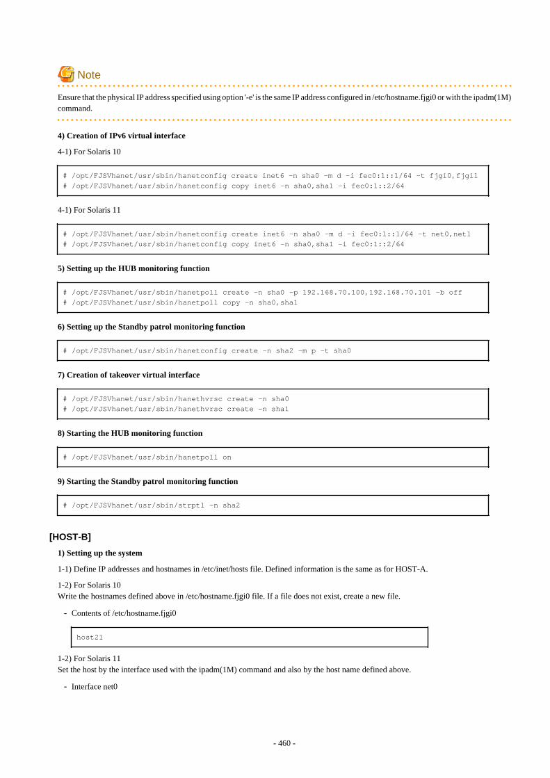
Note
Ensure that the physical IP address specified using option '-e' is the same IP address configured in /etc/hostname.fjgi0 or with the ipadm(1M)command.
4) Creation of IPv6 virtual interface
4-1) For Solaris 10
# /opt/FJSVhanet/usr/sbin/hanetconfig create inet6 -n sha0 -m d -i fec0:1::1/64 -t fjgi0,fjgi1# /opt/FJSVhanet/usr/sbin/hanetconfig copy inet6 -n sha0,sha1 -i fec0:1::2/64
4-1) For Solaris 11
# /opt/FJSVhanet/usr/sbin/hanetconfig create inet6 -n sha0 -m d -i fec0:1::1/64 -t net0,net1# /opt/FJSVhanet/usr/sbin/hanetconfig copy inet6 -n sha0,sha1 -i fec0:1::2/64
5) Setting up the HUB monitoring function
# /opt/FJSVhanet/usr/sbin/hanetpoll create -n sha0 -p 192.168.70.100,192.168.70.101 -b off# /opt/FJSVhanet/usr/sbin/hanetpoll copy -n sha0,sha1
6) Setting up the Standby patrol monitoring function
# /opt/FJSVhanet/usr/sbin/hanetconfig create -n sha2 -m p -t sha0
7) Creation of takeover virtual interface
# /opt/FJSVhanet/usr/sbin/hanethvrsc create -n sha0# /opt/FJSVhanet/usr/sbin/hanethvrsc create -n sha1
8) Starting the HUB monitoring function
# /opt/FJSVhanet/usr/sbin/hanetpoll on
9) Starting the Standby patrol monitoring function
# /opt/FJSVhanet/usr/sbin/strptl -n sha2
[HOST-B]
1) Setting up the system
1-1) Define IP addresses and hostnames in /etc/inet/hosts file. Defined information is the same as for HOST-A.
1-2) For Solaris 10Write the hostnames defined above in /etc/hostname.fjgi0 file. If a file does not exist, create a new file.
- Contents of /etc/hostname.fjgi0
host21
1-2) For Solaris 11Set the host by the interface used with the ipadm(1M) command and also by the host name defined above.
- Interface net0
- 460 -
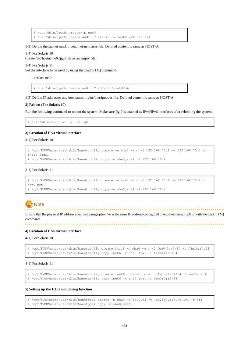
# /usr/sbin/ipadm create-ip net0# /usr/sbin/ipadm create-addr -T static -a host21/24 net0/v4
1-3) Define the subnet mask in /etc/inet/netmasks file. Defined content is same as HOST-A.
1-4) For Solaris 10Create /etc/hostname6.fjgi0 file as an empty file.
1-4) For Solaris 11Set the interface to be used by using the ipadm(1M) command.
- Interface net0
# /usr/sbin/ipadm create-addr -T addrconf net0/v6
1-5) Define IP addresses and hostnames in /etc/inet/ipnodes file. Defined content is same as HOST-A.
2) Reboot (For Solaris 10)
Run the following command to reboot the system. Make sure fjgi0 is enabled as IPv4/IPv6 interfaces after rebooting the system.
# /usr/sbin/shutdown -y -i6 -g0
3) Creation of IPv4 virtual interface
3-1) For Solaris 10
# /opt/FJSVhanet/usr/sbin/hanetconfig create -n sha0 -m d -i 192.168.70.1 -e 192.168.70.4 -t fjgi0,fjgi1# /opt/FJSVhanet/usr/sbin/hanetconfig copy -n sha0,sha1 -i 192.168.70.2
3-1) For Solaris 11
# /opt/FJSVhanet/usr/sbin/hanetconfig create -n sha0 -m d -i 192.168.70.1 -e 192.168.70.4 -t net0,net1# /opt/FJSVhanet/usr/sbin/hanetconfig copy -n sha0,sha1 -i 192.168.70.2
Note
Ensure that the physical IP address specified using option '-e' is the same IP address configured in /etc/hostname.fjgi0 or with the ipadm(1M)command.
4) Creation of IPv6 virtual interface
4-1) For Solaris 10
# /opt/FJSVhanet/usr/sbin/hanetconfig create inet6 -n sha0 -m d -i fec0:1::1/64 -t fjgi0,fjgi1# /opt/FJSVhanet/usr/sbin/hanetconfig copy inet6 -n sha0,sha1 -i fec0:1::2/64
4-1) For Solaris 11
# /opt/FJSVhanet/usr/sbin/hanetconfig create inet6 -n sha0 -m d -i fec0:1::1/64 -t net0,net1# /opt/FJSVhanet/usr/sbin/hanetconfig copy inet6 -n sha0,sha1 -i fec0:1::2/64
5) Setting up the HUB monitoring function
# /opt/FJSVhanet/usr/sbin/hanetpoll create -n sha0 -p 192.168.70.100,192.168.70.101 -b off# /opt/FJSVhanet/usr/sbin/hanetpoll copy -n sha0,sha1
- 461 -
6) Setting up the Standby patrol monitoring function
# /opt/FJSVhanet/usr/sbin/hanetconfig create -n sha2 -m p -t sha0
7) Creation of takeover virtual interface
# /opt/FJSVhanet/usr/sbin/hanethvrsc create -n sha0# /opt/FJSVhanet/usr/sbin/hanethvrsc create -n sha1
8) Starting the HUB monitoring function
# /opt/FJSVhanet/usr/sbin/hanetpoll on
9) Starting the Standby patrol monitoring function
# /opt/FJSVhanet/usr/sbin/strptl -n sha2
[Configuration by Cluster Admin View]
1) Configuration of userApplication
After completing step 9) of both HOST-A and HOST-B, connect to the administration server using Cluster Admin View, then setupthe cluster environment.To create Gls resources, select the SysNode compliant with HOST-A and HOST-B. Once Gls is created, register the two Gls resourceson the userApplication.When registering on the userApplication, select the SysNode compliant with HOST-A and HOST-B in the order of operation nodefollowed by standby node. Then, register the takeover address "192.168.70.1 - fec0:1::1" and "192.168.70.2 - fec0:1::2".
2) Starting of userApplication
After completing the configuration, start the userApplication to activate the takeover virtual interface on the operation node.
B.6.8 Example of the Cluster system (Cascade)This section describes an example configuration procedure of the network shown in the diagram below.
The xx, yy and zz in the figure below are assigned automatically by the automatic address configuration.
For configuring the cluster system, refer to the Cluster system manual.In this section, description of private LAN is omitted. The dotted line indicates that the interface is inactive.
If the Standby patrol monitoring function is not used, omit 6) and 9) in the procedure for setting up on each host.
Note
When using IPv6 address as a takeover virtual interface, it may take around 30 seconds to recover the communication after switching thenode. In order to hold a communication instantly, start IPv6 routing daemon beforehand on both operating and standby nodes. For detailson this issue, refer to "F.2 Troubleshooting".
- 462 -
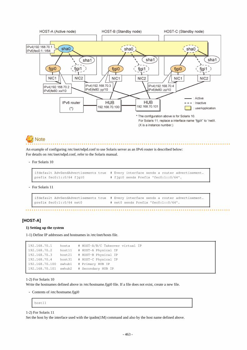
Note
An example of configuring /etc/inet/ndpd.conf to use Solaris server as an IPv6 router is described below:For details on /etc/inet/ndpd.conf, refer to the Solaris manual.
- For Solaris 10
ifdefault AdvSendAdvertisements true # Every interface sends a router advertisement.prefix fec0:1::0/64 fjgi0 # fjgi0 sends Prefix "fec0:1::0/64".
- For Solaris 11
ifdefault AdvSendAdvertisements true # Every interface sends a router advertisement.prefix fec0:1::0/64 net0 # net0 sends Prefix "fec0:1::0/64".
[HOST-A]
1) Setting up the system
1-1) Define IP addresses and hostnames in /etc/inet/hosts file.
192.168.70.1 hosta # HOST-A/B/C Takeover virtual IP192.168.70.2 host11 # HOST-A Physical IP192.168.70.3 host21 # HOST-B Physical IP192.168.70.4 host31 # HOST-C Physical IP192.168.70.100 swhub1 # Primary HUB IP192.168.70.101 swhub2 # Secondary HUB IP
1-2) For Solaris 10Write the hostnames defined above in /etc/hostname.fjgi0 file. If a file does not exist, create a new file.
- Contents of /etc/hostname.fjgi0
host11
1-2) For Solaris 11Set the host by the interface used with the ipadm(1M) command and also by the host name defined above.
- 463 -
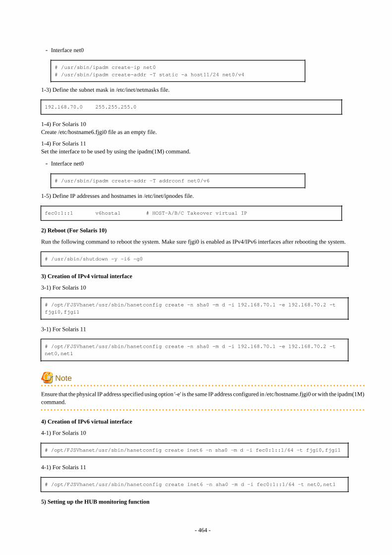
- Interface net0
# /usr/sbin/ipadm create-ip net0# /usr/sbin/ipadm create-addr -T static -a host11/24 net0/v4
1-3) Define the subnet mask in /etc/inet/netmasks file.
192.168.70.0 255.255.255.0
1-4) For Solaris 10Create /etc/hostname6.fjgi0 file as an empty file.
1-4) For Solaris 11Set the interface to be used by using the ipadm(1M) command.
- Interface net0
# /usr/sbin/ipadm create-addr -T addrconf net0/v6
1-5) Define IP addresses and hostnames in /etc/inet/ipnodes file.
fec0:1::1 v6hosta1 # HOST-A/B/C Takeover virtual IP
2) Reboot (For Solaris 10)
Run the following command to reboot the system. Make sure fjgi0 is enabled as IPv4/IPv6 interfaces after rebooting the system.
# /usr/sbin/shutdown -y -i6 -g0
3) Creation of IPv4 virtual interface
3-1) For Solaris 10
# /opt/FJSVhanet/usr/sbin/hanetconfig create -n sha0 -m d -i 192.168.70.1 -e 192.168.70.2 -t fjgi0,fjgi1
3-1) For Solaris 11
# /opt/FJSVhanet/usr/sbin/hanetconfig create -n sha0 -m d -i 192.168.70.1 -e 192.168.70.2 -t net0,net1
Note
Ensure that the physical IP address specified using option '-e' is the same IP address configured in /etc/hostname.fjgi0 or with the ipadm(1M)command.
4) Creation of IPv6 virtual interface
4-1) For Solaris 10
# /opt/FJSVhanet/usr/sbin/hanetconfig create inet6 -n sha0 -m d -i fec0:1::1/64 -t fjgi0,fjgi1
4-1) For Solaris 11
# /opt/FJSVhanet/usr/sbin/hanetconfig create inet6 -n sha0 -m d -i fec0:1::1/64 -t net0,net1
5) Setting up the HUB monitoring function
- 464 -
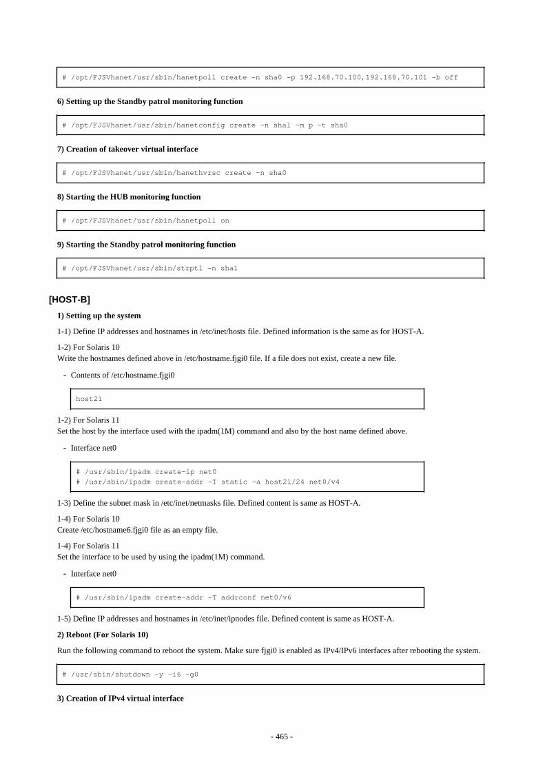
# /opt/FJSVhanet/usr/sbin/hanetpoll create -n sha0 -p 192.168.70.100,192.168.70.101 -b off
6) Setting up the Standby patrol monitoring function
# /opt/FJSVhanet/usr/sbin/hanetconfig create -n sha1 -m p -t sha0
7) Creation of takeover virtual interface
# /opt/FJSVhanet/usr/sbin/hanethvrsc create -n sha0
8) Starting the HUB monitoring function
# /opt/FJSVhanet/usr/sbin/hanetpoll on
9) Starting the Standby patrol monitoring function
# /opt/FJSVhanet/usr/sbin/strptl -n sha1
[HOST-B]
1) Setting up the system
1-1) Define IP addresses and hostnames in /etc/inet/hosts file. Defined information is the same as for HOST-A.
1-2) For Solaris 10Write the hostnames defined above in /etc/hostname.fjgi0 file. If a file does not exist, create a new file.
- Contents of /etc/hostname.fjgi0
host21
1-2) For Solaris 11Set the host by the interface used with the ipadm(1M) command and also by the host name defined above.
- Interface net0
# /usr/sbin/ipadm create-ip net0# /usr/sbin/ipadm create-addr -T static -a host21/24 net0/v4
1-3) Define the subnet mask in /etc/inet/netmasks file. Defined content is same as HOST-A.
1-4) For Solaris 10Create /etc/hostname6.fjgi0 file as an empty file.
1-4) For Solaris 11Set the interface to be used by using the ipadm(1M) command.
- Interface net0
# /usr/sbin/ipadm create-addr -T addrconf net0/v6
1-5) Define IP addresses and hostnames in /etc/inet/ipnodes file. Defined content is same as HOST-A.
2) Reboot (For Solaris 10)
Run the following command to reboot the system. Make sure fjgi0 is enabled as IPv4/IPv6 interfaces after rebooting the system.
# /usr/sbin/shutdown -y -i6 -g0
3) Creation of IPv4 virtual interface
- 465 -
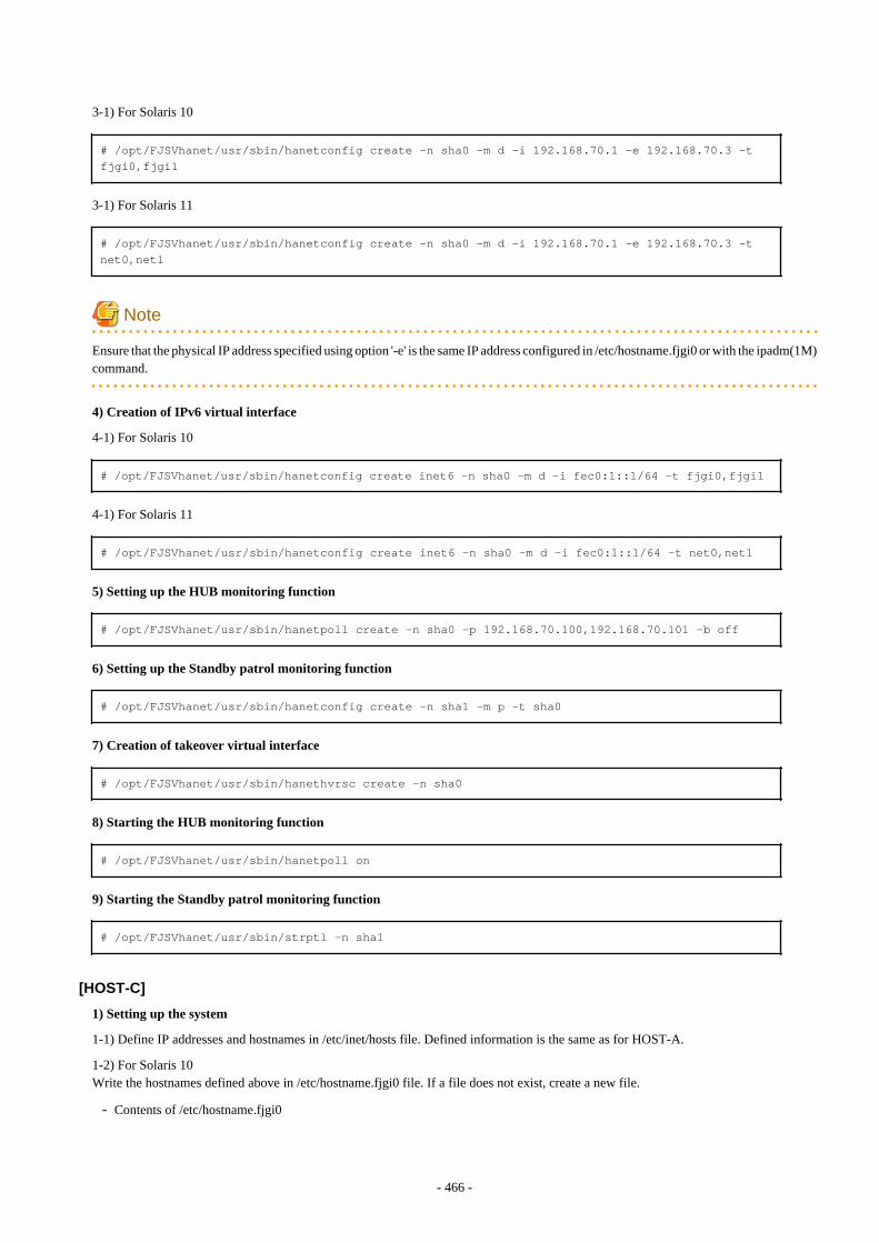
3-1) For Solaris 10
# /opt/FJSVhanet/usr/sbin/hanetconfig create -n sha0 -m d -i 192.168.70.1 -e 192.168.70.3 -t fjgi0,fjgi1
3-1) For Solaris 11
# /opt/FJSVhanet/usr/sbin/hanetconfig create -n sha0 -m d -i 192.168.70.1 -e 192.168.70.3 -t net0,net1
Note
Ensure that the physical IP address specified using option '-e' is the same IP address configured in /etc/hostname.fjgi0 or with the ipadm(1M)command.
4) Creation of IPv6 virtual interface
4-1) For Solaris 10
# /opt/FJSVhanet/usr/sbin/hanetconfig create inet6 -n sha0 -m d -i fec0:1::1/64 -t fjgi0,fjgi1
4-1) For Solaris 11
# /opt/FJSVhanet/usr/sbin/hanetconfig create inet6 -n sha0 -m d -i fec0:1::1/64 -t net0,net1
5) Setting up the HUB monitoring function
# /opt/FJSVhanet/usr/sbin/hanetpoll create -n sha0 -p 192.168.70.100,192.168.70.101 -b off
6) Setting up the Standby patrol monitoring function
# /opt/FJSVhanet/usr/sbin/hanetconfig create -n sha1 -m p -t sha0
7) Creation of takeover virtual interface
# /opt/FJSVhanet/usr/sbin/hanethvrsc create -n sha0
8) Starting the HUB monitoring function
# /opt/FJSVhanet/usr/sbin/hanetpoll on
9) Starting the Standby patrol monitoring function
# /opt/FJSVhanet/usr/sbin/strptl -n sha1
[HOST-C]
1) Setting up the system
1-1) Define IP addresses and hostnames in /etc/inet/hosts file. Defined information is the same as for HOST-A.
1-2) For Solaris 10Write the hostnames defined above in /etc/hostname.fjgi0 file. If a file does not exist, create a new file.
- Contents of /etc/hostname.fjgi0
- 466 -
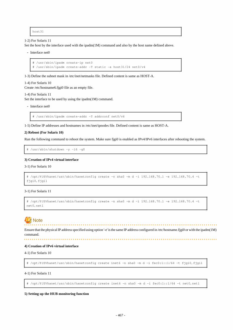
host31
1-2) For Solaris 11Set the host by the interface used with the ipadm(1M) command and also by the host name defined above.
- Interface net0
# /usr/sbin/ipadm create-ip net0# /usr/sbin/ipadm create-addr -T static -a host31/24 net0/v4
1-3) Define the subnet mask in /etc/inet/netmasks file. Defined content is same as HOST-A.
1-4) For Solaris 10Create /etc/hostname6.fjgi0 file as an empty file.
1-4) For Solaris 11Set the interface to be used by using the ipadm(1M) command.
- Interface net0
# /usr/sbin/ipadm create-addr -T addrconf net0/v6
1-5) Define IP addresses and hostnames in /etc/inet/ipnodes file. Defined content is same as HOST-A.
2) Reboot (For Solaris 10)
Run the following command to reboot the system. Make sure fjgi0 is enabled as IPv4/IPv6 interfaces after rebooting the system.
# /usr/sbin/shutdown -y -i6 -g0
3) Creation of IPv4 virtual interface
3-1) For Solaris 10
# /opt/FJSVhanet/usr/sbin/hanetconfig create -n sha0 -m d -i 192.168.70.1 -e 192.168.70.4 -t fjgi0,fjgi1
3-1) For Solaris 11
# /opt/FJSVhanet/usr/sbin/hanetconfig create -n sha0 -m d -i 192.168.70.1 -e 192.168.70.4 -t net0,net1
Note
Ensure that the physical IP address specified using option '-e' is the same IP address configured in /etc/hostname.fjgi0 or with the ipadm(1M)command.
4) Creation of IPv6 virtual interface
4-1) For Solaris 10
# /opt/FJSVhanet/usr/sbin/hanetconfig create inet6 -n sha0 -m d -i fec0:1::1/64 -t fjgi0,fjgi1
4-1) For Solaris 11
# /opt/FJSVhanet/usr/sbin/hanetconfig create inet6 -n sha0 -m d -i fec0:1::1/64 -t net0,net1
5) Setting up the HUB monitoring function
- 467 -
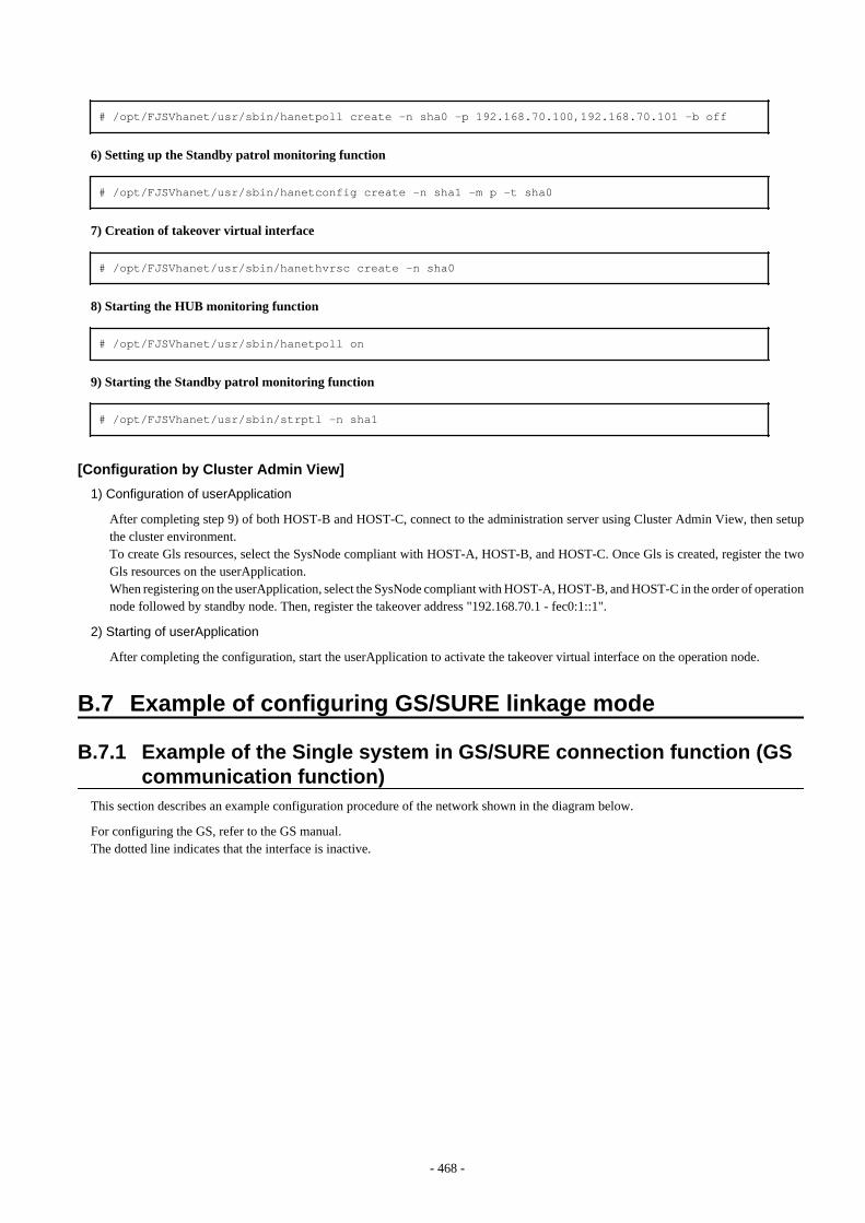
# /opt/FJSVhanet/usr/sbin/hanetpoll create -n sha0 -p 192.168.70.100,192.168.70.101 -b off
6) Setting up the Standby patrol monitoring function
# /opt/FJSVhanet/usr/sbin/hanetconfig create -n sha1 -m p -t sha0
7) Creation of takeover virtual interface
# /opt/FJSVhanet/usr/sbin/hanethvrsc create -n sha0
8) Starting the HUB monitoring function
# /opt/FJSVhanet/usr/sbin/hanetpoll on
9) Starting the Standby patrol monitoring function
# /opt/FJSVhanet/usr/sbin/strptl -n sha1
[Configuration by Cluster Admin View]
1) Configuration of userApplication
After completing step 9) of both HOST-B and HOST-C, connect to the administration server using Cluster Admin View, then setupthe cluster environment.To create Gls resources, select the SysNode compliant with HOST-A, HOST-B, and HOST-C. Once Gls is created, register the twoGls resources on the userApplication.When registering on the userApplication, select the SysNode compliant with HOST-A, HOST-B, and HOST-C in the order of operationnode followed by standby node. Then, register the takeover address "192.168.70.1 - fec0:1::1".
2) Starting of userApplication
After completing the configuration, start the userApplication to activate the takeover virtual interface on the operation node.
B.7 Example of configuring GS/SURE linkage mode
B.7.1 Example of the Single system in GS/SURE connection function (GScommunication function)
This section describes an example configuration procedure of the network shown in the diagram below.
For configuring the GS, refer to the GS manual.The dotted line indicates that the interface is inactive.
- 468 -
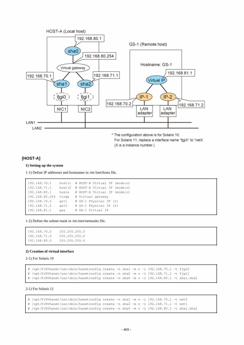
[HOST-A]
1) Setting up the system
1-1) Define IP addresses and hostnames in /etc/inet/hosts file.
192.168.70.1 host11 # HOST-A Virtual IP (mode:n)192.168.71.1 host12 # HOST-A Virtual IP (mode:n)192.168.80.1 hosta # HOST-A Virtual IP (mode:c)192.168.80.254 virgw # Virtual gateway192.168.70.2 gs11 # GS-1 Physical IP (1)192.168.71.2 gs12 # GS-1 Physical IP (2)192.168.81.1 gsa # GS-1 Virtual IP
1-2) Define the subnet mask in /etc/inet/netmasks file.
192.168.70.0 255.255.255.0192.168.71.0 255.255.255.0192.168.80.0 255.255.255.0
2) Creation of virtual interface
2-1) For Solaris 10
# /opt/FJSVhanet/usr/sbin/hanetconfig create -n sha1 -m n -i 192.168.70.1 -t fjgi0# /opt/FJSVhanet/usr/sbin/hanetconfig create -n sha2 -m n -i 192.168.71.1 -t fjgi1# /opt/FJSVhanet/usr/sbin/hanetconfig create -n sha0 -m c -i 192.168.80.1 -t sha1,sha2
2-1) For Solaris 11
# /opt/FJSVhanet/usr/sbin/hanetconfig create -n sha1 -m n -i 192.168.70.1 -t net0# /opt/FJSVhanet/usr/sbin/hanetconfig create -n sha2 -m n -i 192.168.71.1 -t net1# /opt/FJSVhanet/usr/sbin/hanetconfig create -n sha0 -m c -i 192.168.80.1 -t sha1,sha2
- 469 -
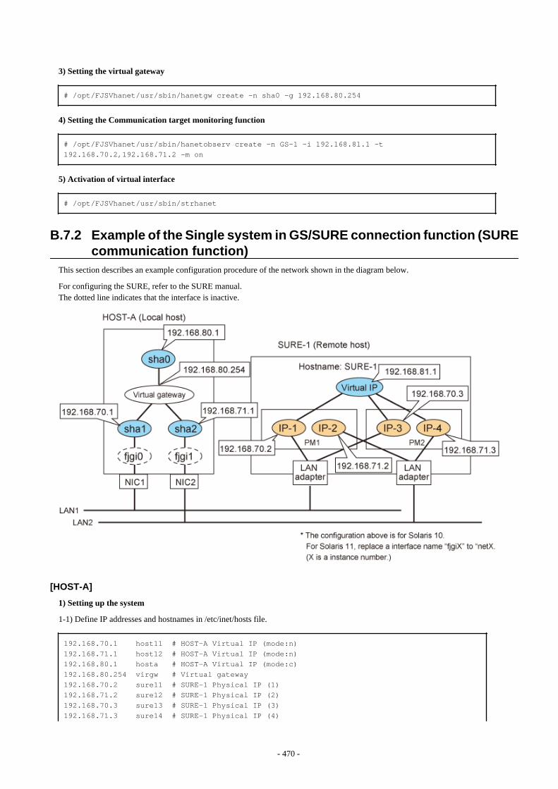
3) Setting the virtual gateway
# /opt/FJSVhanet/usr/sbin/hanetgw create -n sha0 -g 192.168.80.254
4) Setting the Communication target monitoring function
# /opt/FJSVhanet/usr/sbin/hanetobserv create -n GS-1 -i 192.168.81.1 -t 192.168.70.2,192.168.71.2 -m on
5) Activation of virtual interface
# /opt/FJSVhanet/usr/sbin/strhanet
B.7.2 Example of the Single system in GS/SURE connection function (SUREcommunication function)
This section describes an example configuration procedure of the network shown in the diagram below.
For configuring the SURE, refer to the SURE manual.The dotted line indicates that the interface is inactive.
[HOST-A]
1) Setting up the system
1-1) Define IP addresses and hostnames in /etc/inet/hosts file.
192.168.70.1 host11 # HOST-A Virtual IP (mode:n)192.168.71.1 host12 # HOST-A Virtual IP (mode:n)192.168.80.1 hosta # HOST-A Virtual IP (mode:c)192.168.80.254 virgw # Virtual gateway192.168.70.2 sure11 # SURE-1 Physical IP (1)192.168.71.2 sure12 # SURE-1 Physical IP (2)192.168.70.3 sure13 # SURE-1 Physical IP (3)192.168.71.3 sure14 # SURE-1 Physical IP (4)
- 470 -

192.168.81.1 surea # SURE-1 Virtual IP (1)192.168.81.2 sureb # SURE-1 Virtual IP (2)
1-2) Define the subnet mask in /etc/inet/netmasks file.
192.168.70.0 255.255.255.0192.168.71.0 255.255.255.0192.168.80.0 255.255.255.0
2) Creation of virtual interface
2-1) For Solaris 10
# /opt/FJSVhanet/usr/sbin/hanetconfig create -n sha1 -m n -i 192.168.70.1 -t fjgi0# /opt/FJSVhanet/usr/sbin/hanetconfig create -n sha2 -m n -i 192.168.71.1 -t fjgi1# /opt/FJSVhanet/usr/sbin/hanetconfig create -n sha0 -m c -i 192.168.80.1 -t sha1,sha2
2-1) For Solaris 11
# /opt/FJSVhanet/usr/sbin/hanetconfig create -n sha1 -m n -i 192.168.70.1 -t net0# /opt/FJSVhanet/usr/sbin/hanetconfig create -n sha2 -m n -i 192.168.71.1 -t net1# /opt/FJSVhanet/usr/sbin/hanetconfig create -n sha0 -m c -i 192.168.80.1 -t sha1,sha2
3) Setting the virtual gateway
# /opt/FJSVhanet/usr/sbin/hanetgw create -n sha0 -g 192.168.80.254
4) Setting the Communication target monitoring function
# /opt/FJSVhanet/usr/sbin/hanetobserv create -n SURE-1 -i 192.168.81.1 -t 192.168.70.2:1,192.168.71.2:1,192.168.70.3:2,192.168.71.3:2 -m on -r on
5) Activation of virtual interface
# /opt/FJSVhanet/usr/sbin/strhanet
B.7.3 Example of the Single system in GS/SURE connection function (GSHot-standby)
This section describes an example of configuring an environment for GS Hot-standby.
For configuring the GS, refer to the GS manual.The dotted line indicates that the interface is inactive.
- 471 -
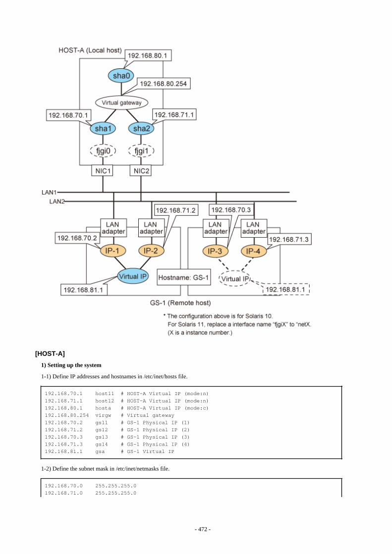
[HOST-A]
1) Setting up the system
1-1) Define IP addresses and hostnames in /etc/inet/hosts file.
192.168.70.1 host11 # HOST-A Virtual IP (mode:n)192.168.71.1 host12 # HOST-A Virtual IP (mode:n)192.168.80.1 hosta # HOST-A Virtual IP (mode:c)192.168.80.254 virgw # Virtual gateway192.168.70.2 gs11 # GS-1 Physical IP (1)192.168.71.2 gs12 # GS-1 Physical IP (2)192.168.70.3 gs13 # GS-1 Physical IP (3)192.168.71.3 gs14 # GS-1 Physical IP (4)192.168.81.1 gsa # GS-1 Virtual IP
1-2) Define the subnet mask in /etc/inet/netmasks file.
192.168.70.0 255.255.255.0192.168.71.0 255.255.255.0
- 472 -
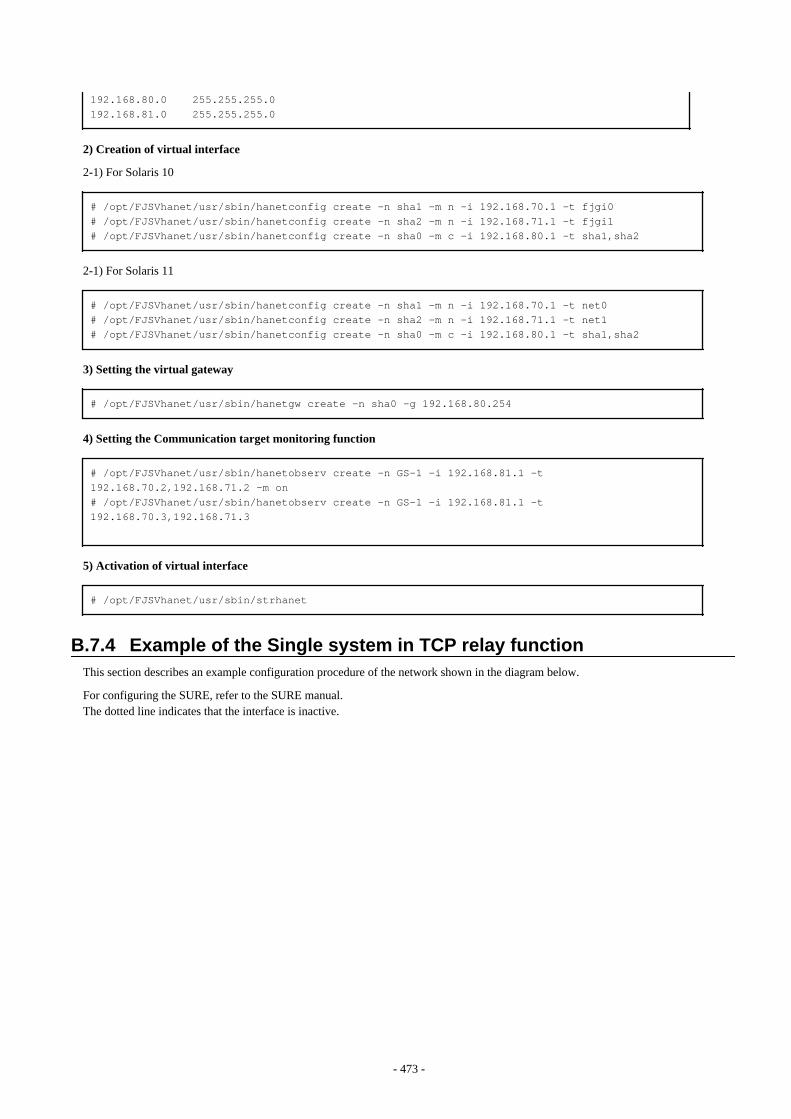
192.168.80.0 255.255.255.0192.168.81.0 255.255.255.0
2) Creation of virtual interface
2-1) For Solaris 10
# /opt/FJSVhanet/usr/sbin/hanetconfig create -n sha1 -m n -i 192.168.70.1 -t fjgi0# /opt/FJSVhanet/usr/sbin/hanetconfig create -n sha2 -m n -i 192.168.71.1 -t fjgi1# /opt/FJSVhanet/usr/sbin/hanetconfig create -n sha0 -m c -i 192.168.80.1 -t sha1,sha2
2-1) For Solaris 11
# /opt/FJSVhanet/usr/sbin/hanetconfig create -n sha1 -m n -i 192.168.70.1 -t net0# /opt/FJSVhanet/usr/sbin/hanetconfig create -n sha2 -m n -i 192.168.71.1 -t net1# /opt/FJSVhanet/usr/sbin/hanetconfig create -n sha0 -m c -i 192.168.80.1 -t sha1,sha2
3) Setting the virtual gateway
# /opt/FJSVhanet/usr/sbin/hanetgw create -n sha0 -g 192.168.80.254
4) Setting the Communication target monitoring function
# /opt/FJSVhanet/usr/sbin/hanetobserv create -n GS-1 -i 192.168.81.1 -t 192.168.70.2,192.168.71.2 -m on# /opt/FJSVhanet/usr/sbin/hanetobserv create -n GS-1 -i 192.168.81.1 -t 192.168.70.3,192.168.71.3
5) Activation of virtual interface
# /opt/FJSVhanet/usr/sbin/strhanet
B.7.4 Example of the Single system in TCP relay functionThis section describes an example configuration procedure of the network shown in the diagram below.
For configuring the SURE, refer to the SURE manual.The dotted line indicates that the interface is inactive.
- 473 -
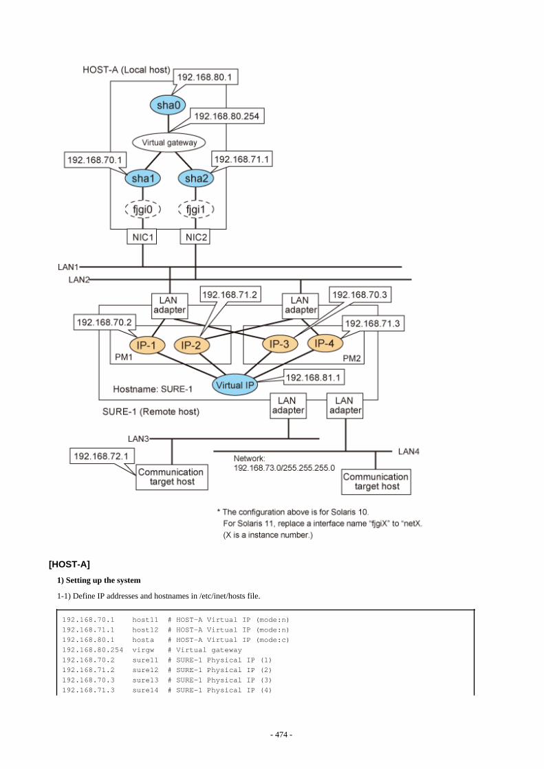
[HOST-A]
1) Setting up the system
1-1) Define IP addresses and hostnames in /etc/inet/hosts file.
192.168.70.1 host11 # HOST-A Virtual IP (mode:n)192.168.71.1 host12 # HOST-A Virtual IP (mode:n)192.168.80.1 hosta # HOST-A Virtual IP (mode:c)192.168.80.254 virgw # Virtual gateway192.168.70.2 sure11 # SURE-1 Physical IP (1)192.168.71.2 sure12 # SURE-1 Physical IP (2)192.168.70.3 sure13 # SURE-1 Physical IP (3)192.168.71.3 sure14 # SURE-1 Physical IP (4)
- 474 -
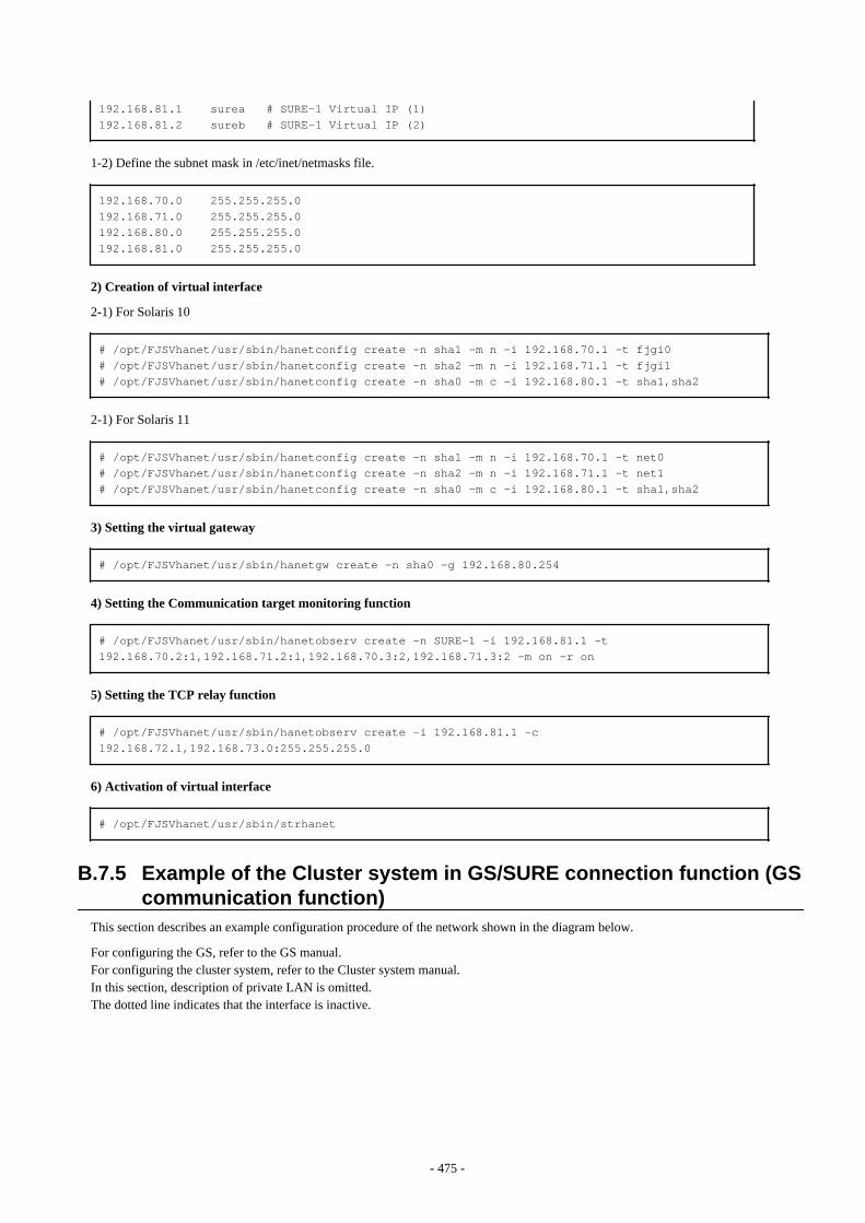
192.168.81.1 surea # SURE-1 Virtual IP (1)192.168.81.2 sureb # SURE-1 Virtual IP (2)
1-2) Define the subnet mask in /etc/inet/netmasks file.
192.168.70.0 255.255.255.0192.168.71.0 255.255.255.0192.168.80.0 255.255.255.0192.168.81.0 255.255.255.0
2) Creation of virtual interface
2-1) For Solaris 10
# /opt/FJSVhanet/usr/sbin/hanetconfig create -n sha1 -m n -i 192.168.70.1 -t fjgi0# /opt/FJSVhanet/usr/sbin/hanetconfig create -n sha2 -m n -i 192.168.71.1 -t fjgi1# /opt/FJSVhanet/usr/sbin/hanetconfig create -n sha0 -m c -i 192.168.80.1 -t sha1,sha2
2-1) For Solaris 11
# /opt/FJSVhanet/usr/sbin/hanetconfig create -n sha1 -m n -i 192.168.70.1 -t net0# /opt/FJSVhanet/usr/sbin/hanetconfig create -n sha2 -m n -i 192.168.71.1 -t net1# /opt/FJSVhanet/usr/sbin/hanetconfig create -n sha0 -m c -i 192.168.80.1 -t sha1,sha2
3) Setting the virtual gateway
# /opt/FJSVhanet/usr/sbin/hanetgw create -n sha0 -g 192.168.80.254
4) Setting the Communication target monitoring function
# /opt/FJSVhanet/usr/sbin/hanetobserv create -n SURE-1 -i 192.168.81.1 -t 192.168.70.2:1,192.168.71.2:1,192.168.70.3:2,192.168.71.3:2 -m on -r on
5) Setting the TCP relay function
# /opt/FJSVhanet/usr/sbin/hanetobserv create -i 192.168.81.1 -c 192.168.72.1,192.168.73.0:255.255.255.0
6) Activation of virtual interface
# /opt/FJSVhanet/usr/sbin/strhanet
B.7.5 Example of the Cluster system in GS/SURE connection function (GScommunication function)
This section describes an example configuration procedure of the network shown in the diagram below.
For configuring the GS, refer to the GS manual.For configuring the cluster system, refer to the Cluster system manual.In this section, description of private LAN is omitted. The dotted line indicates that the interface is inactive.
- 475 -
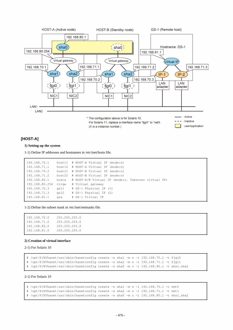
[HOST-A]
1) Setting up the system
1-1) Define IP addresses and hostnames in /etc/inet/hosts file.
192.168.70.1 host11 # HOST-A Virtual IP (mode:n)192.168.71.1 host12 # HOST-A Virtual IP (mode:n)192.168.70.2 host21 # HOST-B Virtual IP (mode:n)192.168.71.2 host22 # HOST-B Virtual IP (mode:n)192.168.80.1 hosta # HOST-A/B Virtual IP (mode:c, Takeover virtual IP)192.168.80.254 virgw # Virtual gateway192.168.70.3 gs11 # GS-1 Physical IP (1)192.168.71.3 gs12 # GS-1 Physical IP (2)192.168.81.1 gsa # GS-1 Virtual IP
1-2) Define the subnet mask in /etc/inet/netmasks file.
192.168.70.0 255.255.255.0192.168.71.0 255.255.255.0192.168.80.0 255.255.255.0192.168.81.0 255.255.255.0
2) Creation of virtual interface
2-1) For Solaris 10
# /opt/FJSVhanet/usr/sbin/hanetconfig create -n sha1 -m n -i 192.168.70.1 -t fjgi0# /opt/FJSVhanet/usr/sbin/hanetconfig create -n sha2 -m n -i 192.168.71.1 -t fjgi1# /opt/FJSVhanet/usr/sbin/hanetconfig create -n sha0 -m c -i 192.168.80.1 -t sha1,sha2
2-1) For Solaris 10
# /opt/FJSVhanet/usr/sbin/hanetconfig create -n sha1 -m n -i 192.168.70.1 -t net0# /opt/FJSVhanet/usr/sbin/hanetconfig create -n sha2 -m n -i 192.168.71.1 -t net1# /opt/FJSVhanet/usr/sbin/hanetconfig create -n sha0 -m c -i 192.168.80.1 -t sha1,sha2
- 476 -

3) Setting the virtual gateway
# /opt/FJSVhanet/usr/sbin/hanetgw create -n sha0 -g 192.168.80.254
4) Setting the Communication target monitoring function
Setting the Remote host monitoring information: # /opt/FJSVhanet/usr/sbin/hanetobserv create -n GS-1 -i 192.168.81.1 -t 192.168.70.3,192.168.71.3 -m on -r on
Setting the Standby node monitoring information: # /opt/FJSVhanet/usr/sbin/hanetobserv create -n HOST-B -i 192.168.80.1 -t 192.168.70.2,192.168.71.2 -m on -r on
Note
When configuring standby node monitoring information, it is necessary to specify the takeover IP address for '-i' option.
5) Creation of takeover virtual interface
# /opt/FJSVhanet/usr/sbin/hanethvrsc create -n sha0
[HOST-B]
1) Setting up the system
1-1) Define IP addresses and hostnames in /etc/inet/hosts file. Defined information is the same as for HOST-A.
1-2) Define the subnet mask in /etc/inet/netmasks file. Defined content is same as HOST-A.
2) Creation of virtual interface
2-1) For Solaris 10
# /opt/FJSVhanet/usr/sbin/hanetconfig create -n sha1 -m n -i 192.168.70.2 -t fjgi0# /opt/FJSVhanet/usr/sbin/hanetconfig create -n sha2 -m n -i 192.168.71.2 -t fjgi1# /opt/FJSVhanet/usr/sbin/hanetconfig create -n sha0 -m c -i 192.168.80.1 -t sha1,sha2
2-1) For Solaris 11
# /opt/FJSVhanet/usr/sbin/hanetconfig create -n sha1 -m n -i 192.168.70.2 -t net0# /opt/FJSVhanet/usr/sbin/hanetconfig create -n sha2 -m n -i 192.168.71.2 -t net1# /opt/FJSVhanet/usr/sbin/hanetconfig create -n sha0 -m c -i 192.168.80.1 -t sha1,sha2
3) Setting the virtual gateway
# /opt/FJSVhanet/usr/sbin/hanetgw create -n sha0 -g 192.168.80.254
4) Setting the Communication target monitoring function
Setting the Remote host monitoring information: # /opt/FJSVhanet/usr/sbin/hanetobserv create -n GS-1 -i 192.168.81.1 -t 192.168.70.3,192.168.71.3 -m on -r on
Setting the Active node monitoring information:
- 477 -
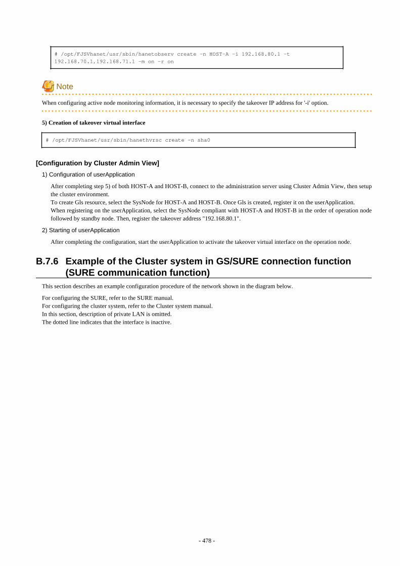
# /opt/FJSVhanet/usr/sbin/hanetobserv create -n HOST-A -i 192.168.80.1 -t 192.168.70.1,192.168.71.1 -m on -r on
Note
When configuring active node monitoring information, it is necessary to specify the takeover IP address for '-i' option.
5) Creation of takeover virtual interface
# /opt/FJSVhanet/usr/sbin/hanethvrsc create -n sha0
[Configuration by Cluster Admin View]
1) Configuration of userApplication
After completing step 5) of both HOST-A and HOST-B, connect to the administration server using Cluster Admin View, then setupthe cluster environment.To create Gls resource, select the SysNode for HOST-A and HOST-B. Once Gls is created, register it on the userApplication.When registering on the userApplication, select the SysNode compliant with HOST-A and HOST-B in the order of operation nodefollowed by standby node. Then, register the takeover address "192.168.80.1".
2) Starting of userApplication
After completing the configuration, start the userApplication to activate the takeover virtual interface on the operation node.
B.7.6 Example of the Cluster system in GS/SURE connection function(SURE communication function)
This section describes an example configuration procedure of the network shown in the diagram below.
For configuring the SURE, refer to the SURE manual.For configuring the cluster system, refer to the Cluster system manual.In this section, description of private LAN is omitted. The dotted line indicates that the interface is inactive.
- 478 -
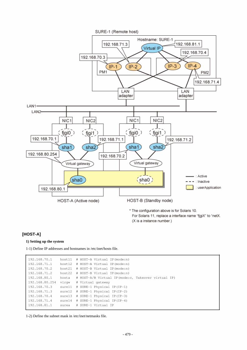
[HOST-A]
1) Setting up the system
1-1) Define IP addresses and hostnames in /etc/inet/hosts file.
192.168.70.1 host11 # HOST-A Virtual IP(mode:n)192.168.71.1 host12 # HOST-A Virtual IP(mode:n)192.168.70.2 host21 # HOST-B Virtual IP(mode:n)192.168.71.2 host22 # HOST-B Virtual IP(mode:n)192.168.80.1 hosta # HOST-A/B Virtual IP(mode:c, Takeover virtual IP)192.168.80.254 virgw # Virtual gateway192.168.70.3 sure11 # SURE-1 Physical IP(IP-1)192.168.71.3 sure12 # SURE-1 Physical IP(IP-2)192.168.70.4 sure13 # SURE-1 Physical IP(IP-3)192.168.71.4 sure14 # SURE-1 Physical IP(IP-4)192.168.81.1 surea # SURE-1 Virtual IP
1-2) Define the subnet mask in /etc/inet/netmasks file.
- 479 -
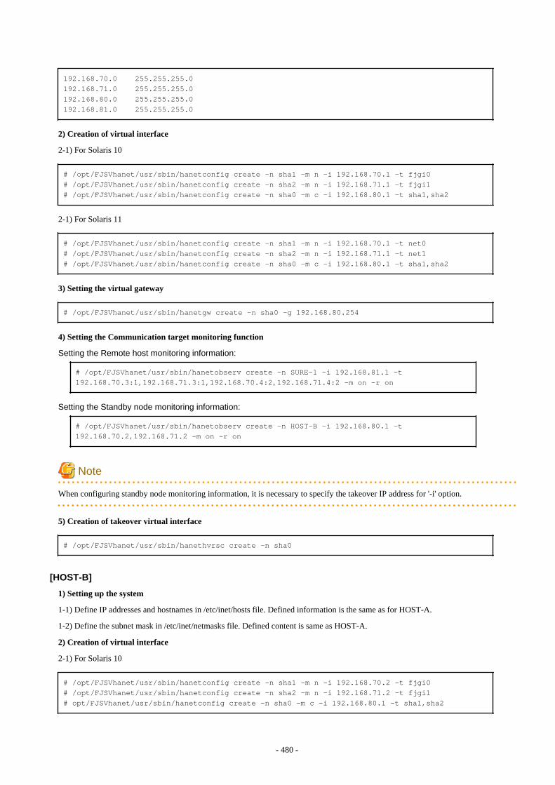
192.168.70.0 255.255.255.0192.168.71.0 255.255.255.0192.168.80.0 255.255.255.0192.168.81.0 255.255.255.0
2) Creation of virtual interface
2-1) For Solaris 10
# /opt/FJSVhanet/usr/sbin/hanetconfig create -n sha1 -m n -i 192.168.70.1 -t fjgi0# /opt/FJSVhanet/usr/sbin/hanetconfig create -n sha2 -m n -i 192.168.71.1 -t fjgi1# /opt/FJSVhanet/usr/sbin/hanetconfig create -n sha0 -m c -i 192.168.80.1 -t sha1,sha2
2-1) For Solaris 11
# /opt/FJSVhanet/usr/sbin/hanetconfig create -n sha1 -m n -i 192.168.70.1 -t net0# /opt/FJSVhanet/usr/sbin/hanetconfig create -n sha2 -m n -i 192.168.71.1 -t net1# /opt/FJSVhanet/usr/sbin/hanetconfig create -n sha0 -m c -i 192.168.80.1 -t sha1,sha2
3) Setting the virtual gateway
# /opt/FJSVhanet/usr/sbin/hanetgw create -n sha0 -g 192.168.80.254
4) Setting the Communication target monitoring function
Setting the Remote host monitoring information: # /opt/FJSVhanet/usr/sbin/hanetobserv create -n SURE-1 -i 192.168.81.1 -t 192.168.70.3:1,192.168.71.3:1,192.168.70.4:2,192.168.71.4:2 -m on -r on
Setting the Standby node monitoring information: # /opt/FJSVhanet/usr/sbin/hanetobserv create -n HOST-B -i 192.168.80.1 -t 192.168.70.2,192.168.71.2 -m on -r on
Note
When configuring standby node monitoring information, it is necessary to specify the takeover IP address for '-i' option.
5) Creation of takeover virtual interface
# /opt/FJSVhanet/usr/sbin/hanethvrsc create -n sha0
[HOST-B]
1) Setting up the system
1-1) Define IP addresses and hostnames in /etc/inet/hosts file. Defined information is the same as for HOST-A.
1-2) Define the subnet mask in /etc/inet/netmasks file. Defined content is same as HOST-A.
2) Creation of virtual interface
2-1) For Solaris 10
# /opt/FJSVhanet/usr/sbin/hanetconfig create -n sha1 -m n -i 192.168.70.2 -t fjgi0# /opt/FJSVhanet/usr/sbin/hanetconfig create -n sha2 -m n -i 192.168.71.2 -t fjgi1# opt/FJSVhanet/usr/sbin/hanetconfig create -n sha0 -m c -i 192.168.80.1 -t sha1,sha2
- 480 -
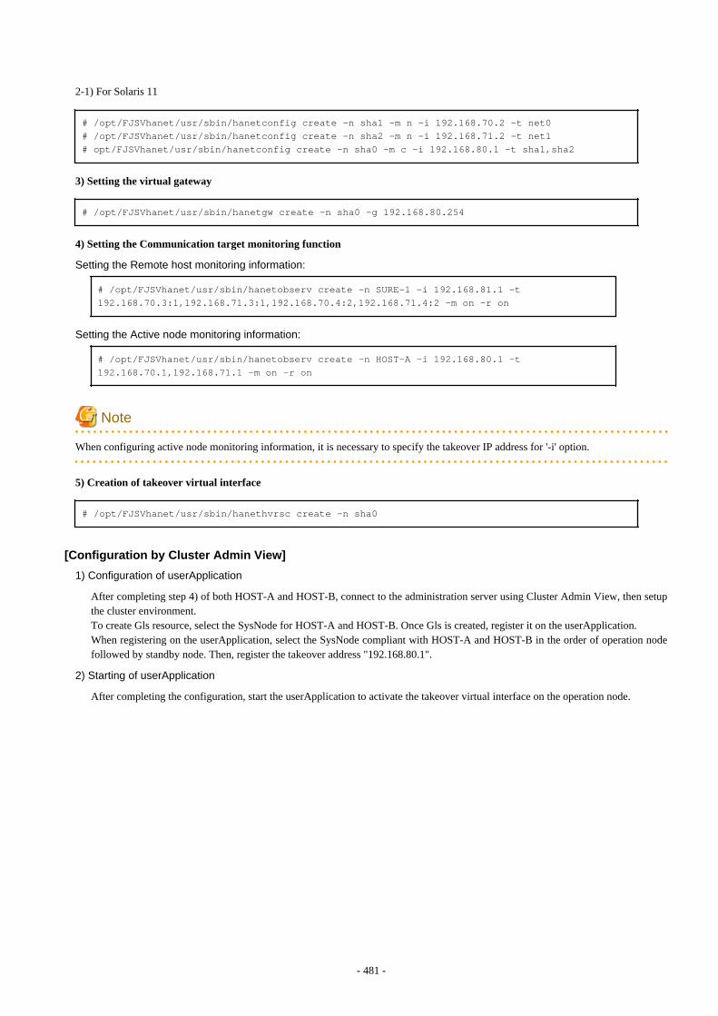
2-1) For Solaris 11
# /opt/FJSVhanet/usr/sbin/hanetconfig create -n sha1 -m n -i 192.168.70.2 -t net0# /opt/FJSVhanet/usr/sbin/hanetconfig create -n sha2 -m n -i 192.168.71.2 -t net1# opt/FJSVhanet/usr/sbin/hanetconfig create -n sha0 -m c -i 192.168.80.1 -t sha1,sha2
3) Setting the virtual gateway
# /opt/FJSVhanet/usr/sbin/hanetgw create -n sha0 -g 192.168.80.254
4) Setting the Communication target monitoring function
Setting the Remote host monitoring information: # /opt/FJSVhanet/usr/sbin/hanetobserv create -n SURE-1 -i 192.168.81.1 -t 192.168.70.3:1,192.168.71.3:1,192.168.70.4:2,192.168.71.4:2 -m on -r on
Setting the Active node monitoring information: # /opt/FJSVhanet/usr/sbin/hanetobserv create -n HOST-A -i 192.168.80.1 -t 192.168.70.1,192.168.71.1 -m on -r on
Note
When configuring active node monitoring information, it is necessary to specify the takeover IP address for '-i' option.
5) Creation of takeover virtual interface
# /opt/FJSVhanet/usr/sbin/hanethvrsc create -n sha0
[Configuration by Cluster Admin View]
1) Configuration of userApplication
After completing step 4) of both HOST-A and HOST-B, connect to the administration server using Cluster Admin View, then setupthe cluster environment.To create Gls resource, select the SysNode for HOST-A and HOST-B. Once Gls is created, register it on the userApplication.When registering on the userApplication, select the SysNode compliant with HOST-A and HOST-B in the order of operation nodefollowed by standby node. Then, register the takeover address "192.168.80.1".
2) Starting of userApplication
After completing the configuration, start the userApplication to activate the takeover virtual interface on the operation node.
- 481 -
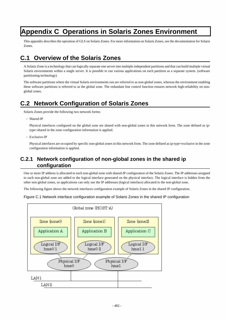
Appendix C Operations in Solaris Zones EnvironmentThis appendix describes the operation of GLS on Solaris Zones. For more information on Solaris Zones, see the documentation for SolarisZones.
C.1 Overview of the Solaris ZonesA Solaris Zone is a technology that can logically separate one server into multiple independent partitions and that can build multiple virtualSolaris environments within a single server. It is possible to run various applications on each partition as a separate system. (softwarepartitioning technology)
The software partitions where the virtual Solaris environments run are referred to as non-global zones, whereas the environment enablingthese software partitions is referred to as the global zone. The redundant line control function ensures network high-reliability on non-global zones.
C.2 Network Configuration of Solaris ZonesSolaris Zones provide the following two network forms:
- Shared-IP
Physical interfaces configured on the global zone are shared with non-global zones in this network form. The zone defined as ip-type=shared in the zone configuration information is applied.
- Exclusive-IP
Physical interfaces are occupied by specific non-global zones in this network form. The zone defined as ip-type=exclusive in the zoneconfiguration information is applied.
C.2.1 Network configuration of non-global zones in the shared ipconfiguration
One or more IP address is allocated to each non-global zone with shared-IP configuration of the Solaris Zones. The IP addresses assignedto each non-global zone are added to the logical interface generated on the physical interface. The logical interface is hidden from theother non-global zones, so applications can only use the IP addresses (logical interface) allocated to the non-global zone.
The following figure shows the network interfaces configuration example of Solaris Zones in the shared IP configuration.
Figure C.1 Network interface configuration example of Solaris Zones in the shared IP configuration
- 482 -
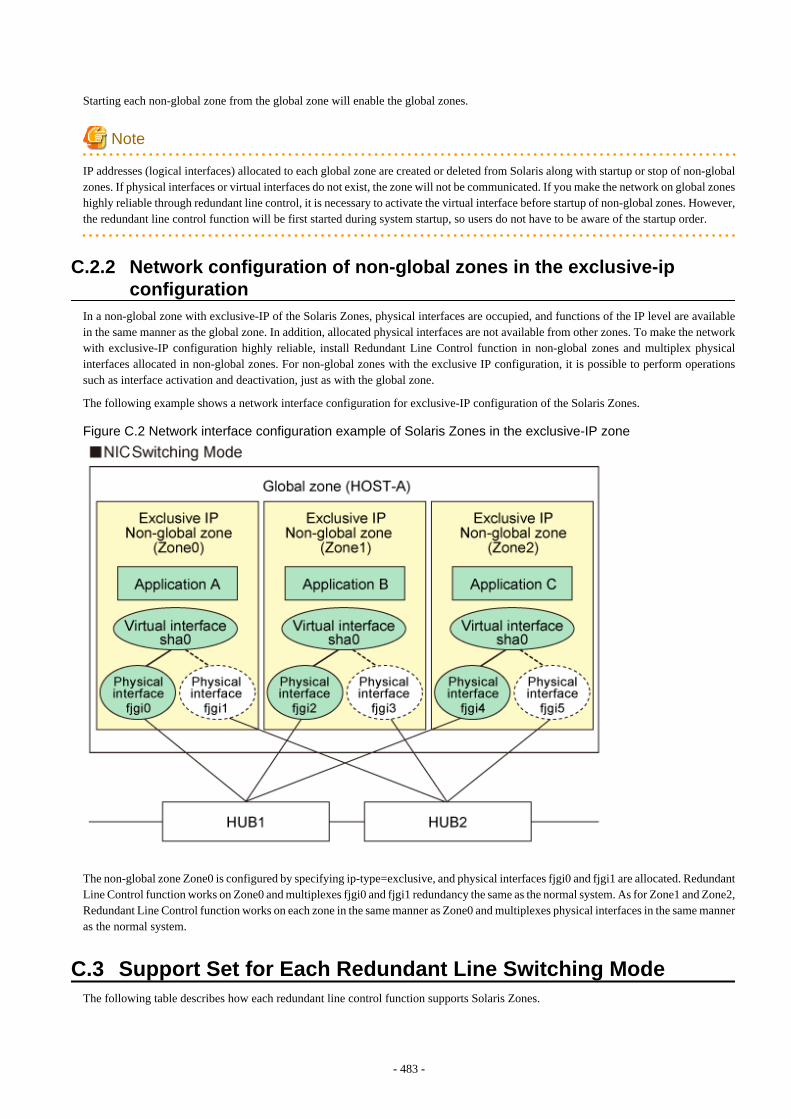
Starting each non-global zone from the global zone will enable the global zones.
Note
IP addresses (logical interfaces) allocated to each global zone are created or deleted from Solaris along with startup or stop of non-globalzones. If physical interfaces or virtual interfaces do not exist, the zone will not be communicated. If you make the network on global zoneshighly reliable through redundant line control, it is necessary to activate the virtual interface before startup of non-global zones. However,the redundant line control function will be first started during system startup, so users do not have to be aware of the startup order.
C.2.2 Network configuration of non-global zones in the exclusive-ipconfiguration
In a non-global zone with exclusive-IP of the Solaris Zones, physical interfaces are occupied, and functions of the IP level are availablein the same manner as the global zone. In addition, allocated physical interfaces are not available from other zones. To make the networkwith exclusive-IP configuration highly reliable, install Redundant Line Control function in non-global zones and multiplex physicalinterfaces allocated in non-global zones. For non-global zones with the exclusive IP configuration, it is possible to perform operationssuch as interface activation and deactivation, just as with the global zone.
The following example shows a network interface configuration for exclusive-IP configuration of the Solaris Zones.
Figure C.2 Network interface configuration example of Solaris Zones in the exclusive-IP zone
The non-global zone Zone0 is configured by specifying ip-type=exclusive, and physical interfaces fjgi0 and fjgi1 are allocated. RedundantLine Control function works on Zone0 and multiplexes fjgi0 and fjgi1 redundancy the same as the normal system. As for Zone1 and Zone2,Redundant Line Control function works on each zone in the same manner as Zone0 and multiplexes physical interfaces in the same manneras the normal system.
C.3 Support Set for Each Redundant Line Switching ModeThe following table describes how each redundant line control function supports Solaris Zones.
- 483 -

[Shared-IP Zones]
The following table shows the support for each redundant mode on the shared-IP zone.
Table C.1 Redundant mode supported on the shared-IP zone
Redundant mode Support
Fast switching mode Supported
NIC switching mode Supported
Virtual NIC mode Supported
GS/SURE linkage mode Supported
[Exclusive-IP Zones]
The following table shows two network configurations are available on the exclusive-IP zones.
- Redundant configuration on the exclusive-IP zones
Configure and use the virtual interface that make a redundant NIC assigned on the exclusive-IP zones.
- Redundant configuration on the global zones
Configure the virtual interface that configures the redundant NIC on the global zones and use this virtual interface on the exclusive-IP zones.
The following table shows the support for each redundant mode on the exclusive-IP zones and the virtual network configurationssupported in each mode.
Table C.2 Redundant mode supported on the exclusive-IP zones
Redundant mode Support Corresponding virtual networkconfiguration on the Global zone
Fast switching mode Unsupported -
NIC switching mode Supported Redundant configuration on the exclusive-IP zones
Virtual NIC mode Supported Redundant configuration on the global zone
GS/SURE linkage mode Unsupported -
Information
- When you make the shared-IP zone network highly reliable through NIC switching, use physical IP takeover (operation mode "e").If you use logical IP takeover (operation mode "d"), the redundant line control function will activate a logical IP address as a takeoverIP address as well as Solaris will activate another logical IP address during zone startup, which means the unnecessary IP address notused by the zone will be activated. If you add the zone settings after setting logical IP takeover (operation mode "d"), it is not necessaryto change it to physical IP takeover (operation mode "e").
- The virtual IP address, logical IP address, and physical IP address allocated through redundant line control of the global zone can beused in the global zone only. The operating system will allocate IP addresses to the non-global zone during zone startup.
- In the environment of Solaris 11.1 or later, the following configuration enables to make a redundant using the same physical NIC onthe exclusive-IP zones and the global zone.
- Create VNIC to each physical NIC on the global zone and make the VNIC redundant on the exclusive-IP zones.
- Directly make the physical NIC redundant on the global zone.
- To use the virtual NIC mode on the exclusive-IP zones, see "Exclusive-IP zones" in "PRIMECLUSTER Global Link ServicesConfiguration and Administration Guide: Redundant Line Control Function for Virtual NIC Mode."
- 484 -
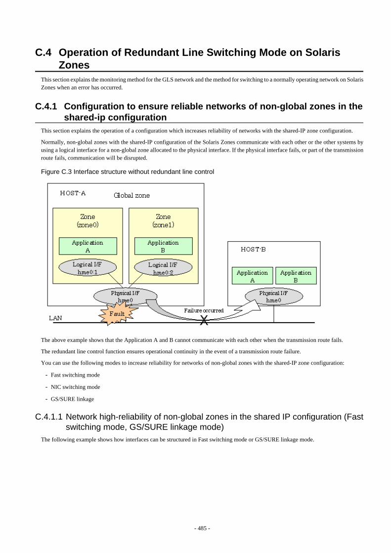
C.4 Operation of Redundant Line Switching Mode on SolarisZones
This section explains the monitoring method for the GLS network and the method for switching to a normally operating network on SolarisZones when an error has occurred.
C.4.1 Configuration to ensure reliable networks of non-global zones in theshared-ip configuration
This section explains the operation of a configuration which increases reliability of networks with the shared-IP zone configuration.
Normally, non-global zones with the shared-IP configuration of the Solaris Zones communicate with each other or the other systems byusing a logical interface for a non-global zone allocated to the physical interface. If the physical interface fails, or part of the transmissionroute fails, communication will be disrupted.
Figure C.3 Interface structure without redundant line control
The above example shows that the Application A and B cannot communicate with each other when the transmission route fails.
The redundant line control function ensures operational continuity in the event of a transmission route failure.
You can use the following modes to increase reliability for networks of non-global zones with the shared-IP zone configuration:
- Fast switching mode
- NIC switching mode
- GS/SURE linkage
C.4.1.1 Network high-reliability of non-global zones in the shared IP configuration (Fastswitching mode, GS/SURE linkage mode)
The following example shows how interfaces can be structured in Fast switching mode or GS/SURE linkage mode.
- 485 -
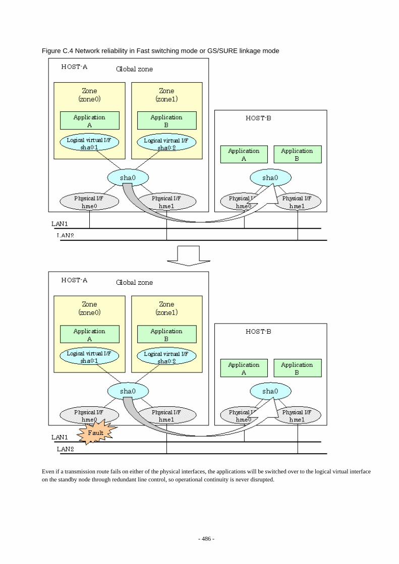
Figure C.4 Network reliability in Fast switching mode or GS/SURE linkage mode
Even if a transmission route fails on either of the physical interfaces, the applications will be switched over to the logical virtual interfaceon the standby node through redundant line control, so operational continuity is never disrupted.
- 486 -
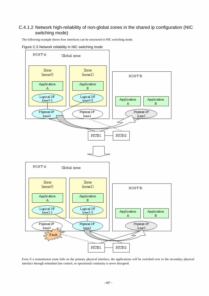
C.4.1.2 Network high-reliability of non-global zones in the shared ip configuration (NICswitching mode)
The following example shows how interfaces can be structured in NIC switching mode.
Figure C.5 Network reliability in NIC switching mode
Even if a transmission route fails on the primary physical interface, the applications will be switched over to the secondary physicalinterface through redundant line control, so operational continuity is never disrupted.
- 487 -
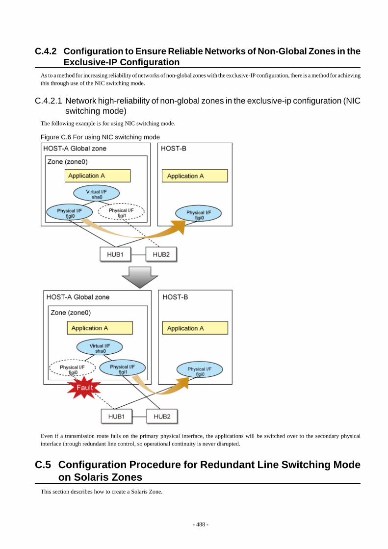
C.4.2 Configuration to Ensure Reliable Networks of Non-Global Zones in theExclusive-IP Configuration
As to a method for increasing reliability of networks of non-global zones with the exclusive-IP configuration, there is a method for achievingthis through use of the NIC switching mode.
C.4.2.1 Network high-reliability of non-global zones in the exclusive-ip configuration (NICswitching mode)
The following example is for using NIC switching mode.
Figure C.6 For using NIC switching mode
Even if a transmission route fails on the primary physical interface, the applications will be switched over to the secondary physicalinterface through redundant line control, so operational continuity is never disrupted.
C.5 Configuration Procedure for Redundant Line Switching Modeon Solaris Zones
This section describes how to create a Solaris Zone.
- 488 -
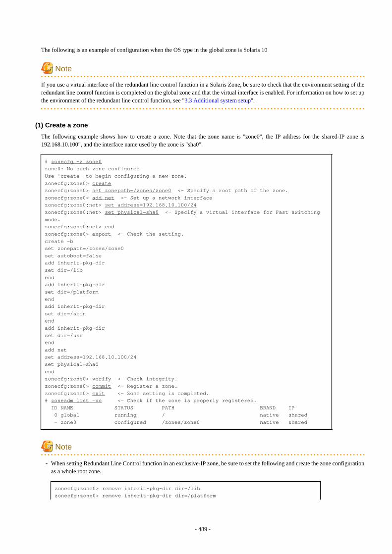
The following is an example of configuration when the OS type in the global zone is Solaris 10
Note
If you use a virtual interface of the redundant line control function in a Solaris Zone, be sure to check that the environment setting of theredundant line control function is completed on the global zone and that the virtual interface is enabled. For information on how to set upthe environment of the redundant line control function, see "3.3 Additional system setup".
(1) Create a zone
The following example shows how to create a zone. Note that the zone name is "zone0", the IP address for the shared-IP zone is192.168.10.100", and the interface name used by the zone is "sha0".
# zonecfg -z zone0zone0: No such zone configuredUse 'create' to begin configuring a new zone.zonecfg:zone0> createzonecfg:zone0> set zonepath=/zones/zone0 <- Specify a root path of the zone.zonecfg:zone0> add net <- Set up a network interfacezonecfg:zone0:net> set address=192.168.10.100/24zonecfg:zone0:net> set physical=sha0 <- Specify a virtual interface for Fast switching mode.zonecfg:zone0:net> endzonecfg:zone0> export <- Check the setting.create -bset zonepath=/zones/zone0set autoboot=falseadd inherit-pkg-dirset dir=/libendadd inherit-pkg-dirset dir=/platformendadd inherit-pkg-dirset dir=/sbinendadd inherit-pkg-dirset dir=/usrendadd netset address=192.168.10.100/24set physical=sha0endzonecfg:zone0> verify <- Check integrity.zonecfg:zone0> commit <- Register a zone.zonecfg:zone0> exit <- Zone setting is completed.# zoneadm list -vc <- Check if the zone is properly registered. ID NAME STATUS PATH BRAND IP 0 global running / native shared - zone0 configured /zones/zone0 native shared
Note
- When setting Redundant Line Control function in an exclusive-IP zone, be sure to set the following and create the zone configurationas a whole root zone.
zonecfg:zone0> remove inherit-pkg-dir dir=/libzonecfg:zone0> remove inherit-pkg-dir dir=/platform
- 489 -
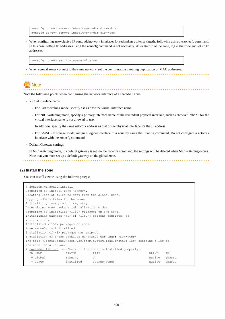
zonecfg:zone0> remove inherit-pkg-dir dir=/sbinzonecfg:zone0> remove inherit-pkg-dir dir=/usr
- When configuring an exclusive-IP zone, add network interfaces for redundancy after setting the following using the zonecfg command.In this case, setting IP addresses using the zonecfg command is not necessary. After startup of the zone, log in the zone and set up IPaddresses.
zonecfg:zone0> set ip-type=exclusive
- When sereval zones connect to the same network, set the configuration avoiding duplication of MAC addresses.
Note
Note the following points when configuring the network interface of a shared-IP zone.
- Virtual interface name
- For Fast switching mode, specify "shaX" for the virtual interface name.
- For NIC switching mode, specify a primary interface name of the redundant physical interface, such as "hmeX". "shaX" for thevirtual interface name is not allowed to use.
In addition, specify the same network address as that of the physical interface for the IP address.
- For GS/SURE linkage mode, assign a logical interface to a zone by using the ifconfig command. Do not configure a networkinterface with the zonecfg command.
- Default Gateway settings
In NIC switching mode, if a default gateway is set via the zonecfg command, the settings will be deleted when NIC switching occurs.Note that you must set up a default gateway on the global zone.
(2) Install the zone
You can install a zone using the following steps;
# zoneadm -z zone0 installPreparing to install zone <zone0>.Creating list of files to copy from the global zone.Copying <3370> files to the zone.Initializing zone product registry.Determining zone package initialization order.Preparing to initialize <1150> packages on the zone.Initializing package <40> of <1150>: percent complete: 3%. . . . . . . .Initialized <1150> packages on zone.Zone <zone0> is initialized.Installation of <2> packages was skipped.Installation of these packages generated warnings: <SUNWvtsr>The file </zones/zone0/root/var/sadm/system/logs/install_log> contains a log ofthe zone installation.# zoneadm list -vc <- Check if the zone is installed properly. ID NAME STATUS PATH BRAND IP 0 global running / native shared - zone0 installed /zones/zone0 native shared
- 490 -
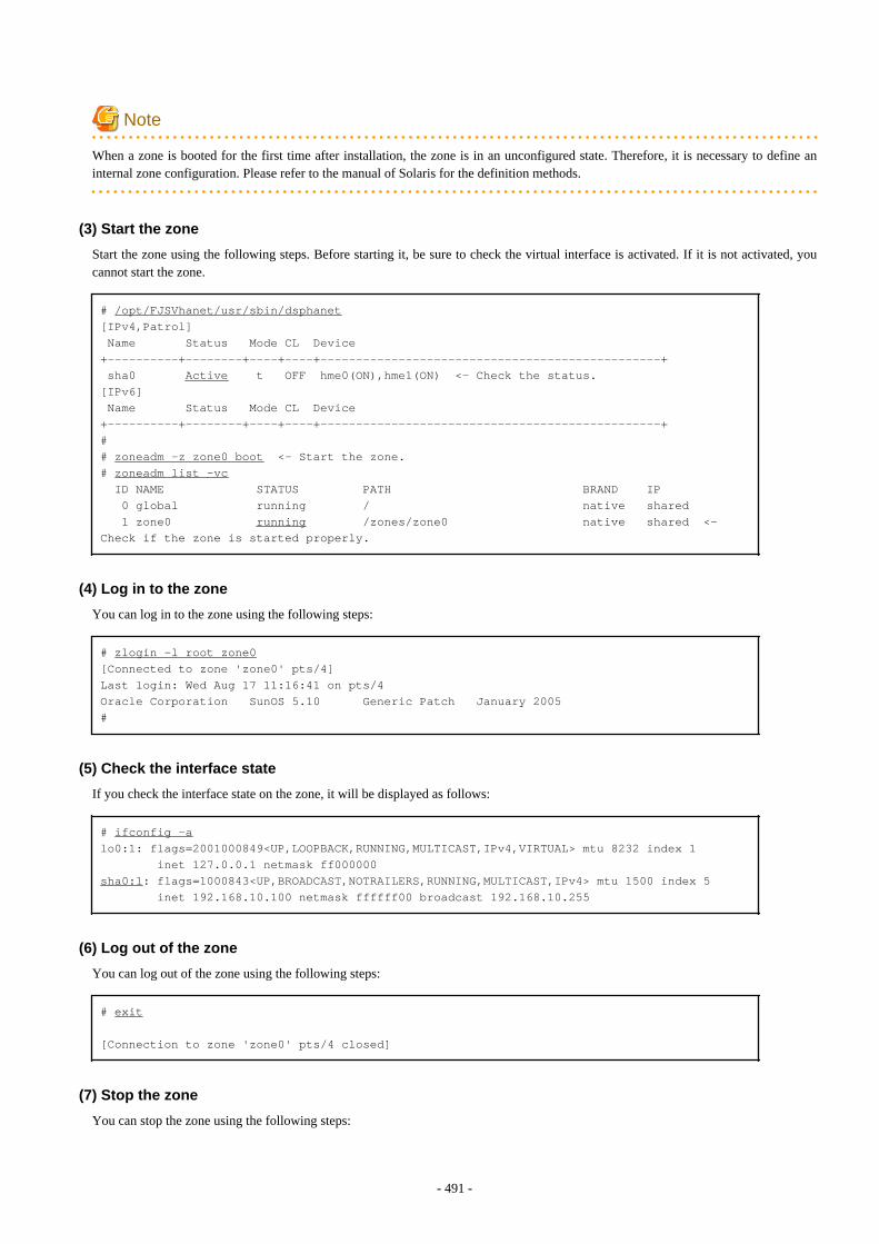
Note
When a zone is booted for the first time after installation, the zone is in an unconfigured state. Therefore, it is necessary to define aninternal zone configuration. Please refer to the manual of Solaris for the definition methods.
(3) Start the zone
Start the zone using the following steps. Before starting it, be sure to check the virtual interface is activated. If it is not activated, youcannot start the zone.
# /opt/FJSVhanet/usr/sbin/dsphanet[IPv4,Patrol] Name Status Mode CL Device+----------+--------+----+----+------------------------------------------------+ sha0 Active t OFF hme0(ON),hme1(ON) <- Check the status.[IPv6] Name Status Mode CL Device+----------+--------+----+----+------------------------------------------------+# # zoneadm -z zone0 boot <- Start the zone.# zoneadm list -vc ID NAME STATUS PATH BRAND IP 0 global running / native shared 1 zone0 running /zones/zone0 native shared <- Check if the zone is started properly.
(4) Log in to the zone
You can log in to the zone using the following steps:
# zlogin -l root zone0[Connected to zone 'zone0' pts/4]Last login: Wed Aug 17 11:16:41 on pts/4Oracle Corporation SunOS 5.10 Generic Patch January 2005#
(5) Check the interface state
If you check the interface state on the zone, it will be displayed as follows:
# ifconfig -alo0:1: flags=2001000849<UP,LOOPBACK,RUNNING,MULTICAST,IPv4,VIRTUAL> mtu 8232 index 1 inet 127.0.0.1 netmask ff000000sha0:1: flags=1000843<UP,BROADCAST,NOTRAILERS,RUNNING,MULTICAST,IPv4> mtu 1500 index 5 inet 192.168.10.100 netmask ffffff00 broadcast 192.168.10.255
(6) Log out of the zone
You can log out of the zone using the following steps:
# exit
[Connection to zone 'zone0' pts/4 closed]
(7) Stop the zone
You can stop the zone using the following steps:
- 491 -
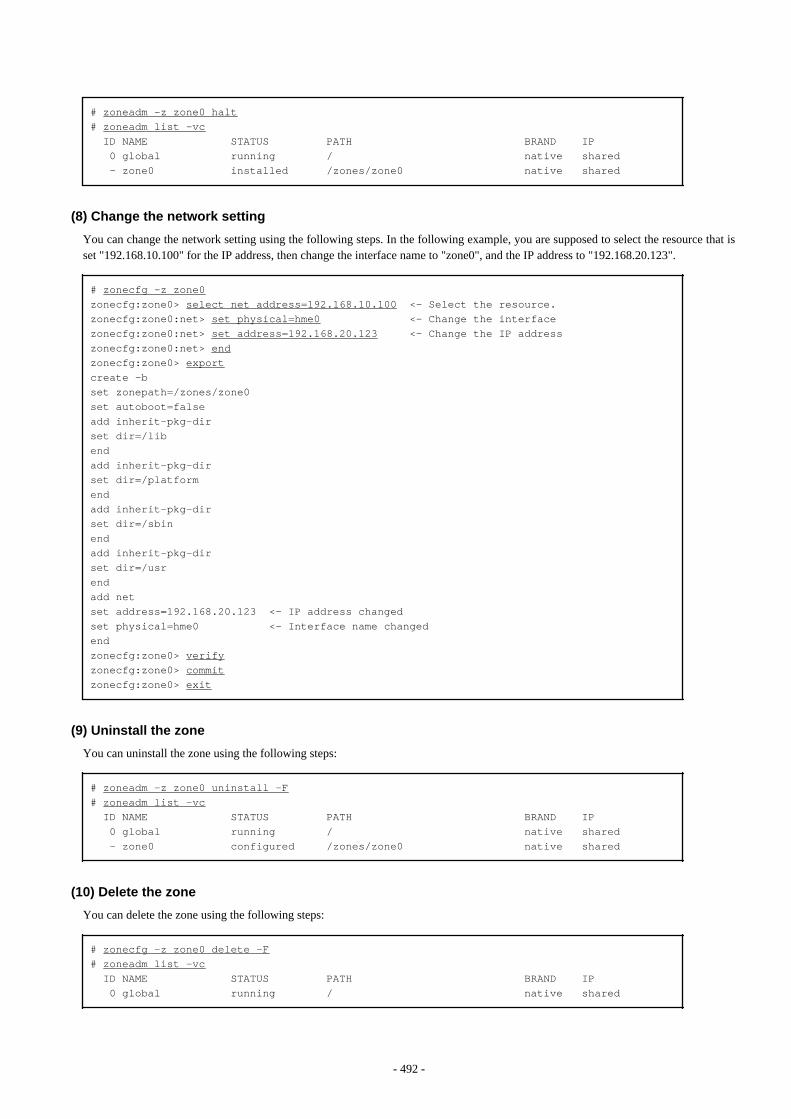
# zoneadm -z zone0 halt# zoneadm list -vc ID NAME STATUS PATH BRAND IP 0 global running / native shared - zone0 installed /zones/zone0 native shared
(8) Change the network setting
You can change the network setting using the following steps. In the following example, you are supposed to select the resource that isset "192.168.10.100" for the IP address, then change the interface name to "zone0", and the IP address to "192.168.20.123".
# zonecfg -z zone0zonecfg:zone0> select net address=192.168.10.100 <- Select the resource.zonecfg:zone0:net> set physical=hme0 <- Change the interfacezonecfg:zone0:net> set address=192.168.20.123 <- Change the IP addresszonecfg:zone0:net> endzonecfg:zone0> exportcreate -bset zonepath=/zones/zone0set autoboot=falseadd inherit-pkg-dirset dir=/libendadd inherit-pkg-dirset dir=/platformendadd inherit-pkg-dirset dir=/sbinendadd inherit-pkg-dirset dir=/usrendadd netset address=192.168.20.123 <- IP address changedset physical=hme0 <- Interface name changedendzonecfg:zone0> verifyzonecfg:zone0> commitzonecfg:zone0> exit
(9) Uninstall the zone
You can uninstall the zone using the following steps:
# zoneadm -z zone0 uninstall -F# zoneadm list -vc ID NAME STATUS PATH BRAND IP 0 global running / native shared - zone0 configured /zones/zone0 native shared
(10) Delete the zone
You can delete the zone using the following steps:
# zonecfg -z zone0 delete -F# zoneadm list -vc ID NAME STATUS PATH BRAND IP 0 global running / native shared
- 492 -

See
For further details, see the "Solaris 10 OS" manual.
C.6 Examples of Configuring System EnvironmentsThis appendix explains how to configure the system environment with redundant network control.
IP addresses used in examples of configuring system environments are all local IP addresses. You can specify these IP addresses with hostnames.
Moreover, interface names listed in examples of configuring system environments vary depending on the environment. Replace interfacenames according to the environment. For Solaris 11, the default interface name is netX (X means the instance number).
C.6.1 Configuration Example to Ensure Network Reliability of Non-GlobalZones in the Shared-IP Configuration
This section explains how to configure highly reliable networks of non-global zones with the shared IP configuration.
C.6.1.1 Example of configuration with Fast switching mode (IPv4)This section describes an example configuration procedure of the network shown in the diagram below.
[HOST-A]
1) Setting up the system
1-1) Define IP addresses and hostnames in /etc/inet/hosts file.
192.168.70.1 host11 # HOST-A Physical IP (1)192.168.71.1 host12 # HOST-A Physical IP (2)192.168.80.1 hosta # HOST-A Virtual IP192.168.70.2 host21 # HOST-B Physical IP (1)192.168.71.2 host22 # HOST-B Physical IP (2)192.168.80.2 hostb # HOST-B Virtual IP192.168.80.10 zone0 # zone0 Logical IP
- 493 -

1-2) For Solaris 10Write the hostnames defined above in /etc/hostname.fjgi0 file and /etc/hostname.fjgi1 file. If a file does not exist, create a new file.
- Contents of /etc/hostname.fjgi0
host11
- Contents of /etc/hostname.fjgi1
host12
1-2) For Solaris 11
Set the host by the interface used with the ipadm(1M) command and also by the host name defined above.
- Interface net0
# /usr/sbin/ipadm create-ip net0# /usr/sbin/ipadm create-addr -T static -a host11/24 net0/v4
- Interface net1
# /usr/sbin/ipadm create-ip net1# /usr/sbin/ipadm create-addr -T static -a host12/24 net1/v4
1-3) Define the subnet mask in /etc/inet/netmasks file.
192.168.70.0 255.255.255.0192.168.71.0 255.255.255.0192.168.80.0 255.255.255.0
2) Reboot (For Solaris 10)
Run the following command to reboot the system. Make sure fjgi0 and fjgi1 are enabled as IPv4 interfaces after rebooting the system.
# /usr/sbin/shutdown -y -i6 -g0
3) Creation of virtual interface
3-1) For Solaris 10
# /opt/FJSVhanet/usr/sbin/hanetconfig create -n sha0 -m t -i 192.168.80.1 -t fjgi0,fjgi1
3-1) For Solaris 11
# /opt/FJSVhanet/usr/sbin/hanetconfig create -n sha0 -m t -i 192.168.80.1 -t net0,net1
4) Activation of virtual interface
# /opt/FJSVhanet/usr/sbin/strhanet
5) Set up a zone
Set up a zone by executing the following command:
# /usr/sbin/zonecfg -z zone0
5-1) Create a zone.
- 494 -
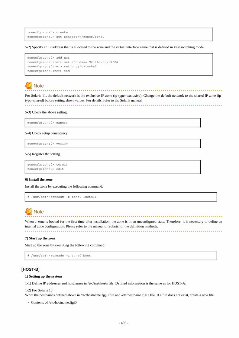
zonecfg:zone0> createzonecfg:zone0> set zonepath=/zones/zone0
5-2) Specify an IP address that is allocated to the zone and the virtual interface name that is defined in Fast switching mode.
zonecfg:zone0> add netzonecfg:zone0:net> set address=192.168.80.10/24zonecfg:zone0:net> set physical=sha0zonecfg:zone0:net> end
Note
For Solaris 11, the default network is the exclusive-IP zone (ip-type=exclusive). Change the default network to the shared IP zone (ip-type=shared) before setting above values. For details, refer to the Solaris manual.
5-3) Check the above setting.
zonecfg:zone0> export
5-4) Check setup consistency.
zonecfg:zone0> verify
5-5) Register the setting.
zonecfg:zone0> commitzonecfg:zone0> exit
6) Install the zone
Install the zone by executing the following command:
# /usr/sbin/zoneadm -z zone0 install
Note
When a zone is booted for the first time after installation, the zone is in an unconfigured state. Therefore, it is necessary to define aninternal zone configuration. Please refer to the manual of Solaris for the definition methods.
7) Start up the zone
Start up the zone by executing the following command:
# /usr/sbin/zoneadm -z zone0 boot
[HOST-B]
1) Setting up the system
1-1) Define IP addresses and hostnames in /etc/inet/hosts file. Defined information is the same as for HOST-A.
1-2) For Solaris 10Write the hostnames defined above in /etc/hostname.fjgi0 file and /etc/hostname.fjgi1 file. If a file does not exist, create a new file.
- Contents of /etc/hostname.fjgi0
- 495 -
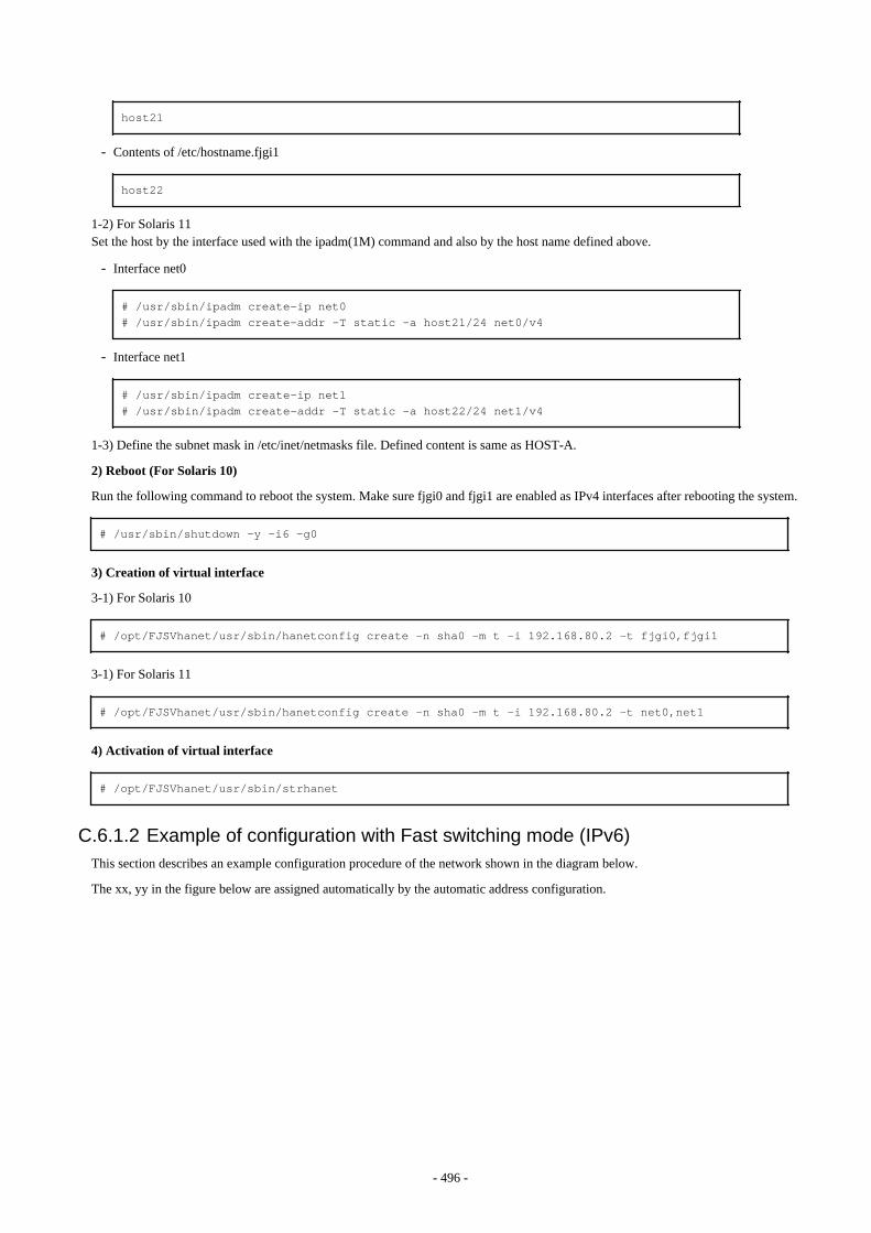
host21
- Contents of /etc/hostname.fjgi1
host22
1-2) For Solaris 11Set the host by the interface used with the ipadm(1M) command and also by the host name defined above.
- Interface net0
# /usr/sbin/ipadm create-ip net0# /usr/sbin/ipadm create-addr -T static -a host21/24 net0/v4
- Interface net1
# /usr/sbin/ipadm create-ip net1# /usr/sbin/ipadm create-addr -T static -a host22/24 net1/v4
1-3) Define the subnet mask in /etc/inet/netmasks file. Defined content is same as HOST-A.
2) Reboot (For Solaris 10)
Run the following command to reboot the system. Make sure fjgi0 and fjgi1 are enabled as IPv4 interfaces after rebooting the system.
# /usr/sbin/shutdown -y -i6 -g0
3) Creation of virtual interface
3-1) For Solaris 10
# /opt/FJSVhanet/usr/sbin/hanetconfig create -n sha0 -m t -i 192.168.80.2 -t fjgi0,fjgi1
3-1) For Solaris 11
# /opt/FJSVhanet/usr/sbin/hanetconfig create -n sha0 -m t -i 192.168.80.2 -t net0,net1
4) Activation of virtual interface
# /opt/FJSVhanet/usr/sbin/strhanet
C.6.1.2 Example of configuration with Fast switching mode (IPv6)This section describes an example configuration procedure of the network shown in the diagram below.
The xx, yy in the figure below are assigned automatically by the automatic address configuration.
- 496 -

[HOST-A]
1) Setting up the system
1-1) Create /etc/inet/ndpd.conf file and set the followings:
ifdefault AdvSendAdvertisements true # Every interface sends a router advertisement.prefix fec0:1::0/64 sha0 # sha0 sends Prefix "fec0:1::0/64".
Note
In the Solaris server that runs Fast switching mode, configure two or more router as IPv6 router. If the IPv6 router breaks down, it cannotuse site-local address to communicate. To prevent this, it is recommended to setup at least two IPv6 routers.For details on /etc/inet/ndpd.conf, refer to the Solaris manual.
1-2) For Solaris 10Create /etc/hostname6.fjgi0 and /etc/hostname6.fjgi1 files as an empty file.
1-2) For Solaris 11Set the interface to be used by using the ipadm(1M) command.
- Interface net0
# /usr/sbin/ipadm create-ip net0# /usr/sbin/ipadm create-addr -T addrconf net0/v6
- Interface net1
# /usr/sbin/ipadm create-ip net1# /usr/sbin/ipadm create-addr -T addrconf net1/v6
2) Reboot (For Solaris 10)
Run the following command to reboot the system. Make sure fjgi0 and fjgi1 are enabled as IPv6 interfaces after rebooting the system.
- 497 -
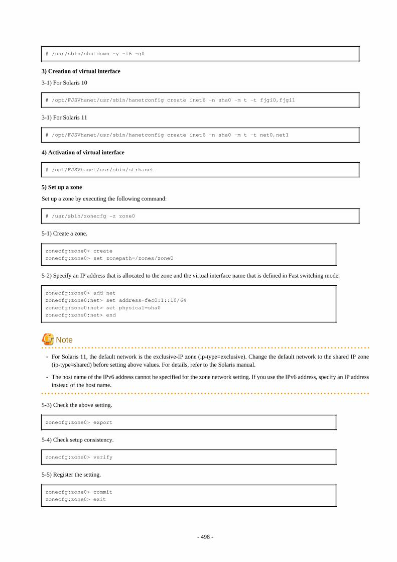
# /usr/sbin/shutdown -y -i6 -g0
3) Creation of virtual interface
3-1) For Solaris 10
# /opt/FJSVhanet/usr/sbin/hanetconfig create inet6 -n sha0 -m t -t fjgi0,fjgi1
3-1) For Solaris 11
# /opt/FJSVhanet/usr/sbin/hanetconfig create inet6 -n sha0 -m t -t net0,net1
4) Activation of virtual interface
# /opt/FJSVhanet/usr/sbin/strhanet
5) Set up a zone
Set up a zone by executing the following command:
# /usr/sbin/zonecfg -z zone0
5-1) Create a zone.
zonecfg:zone0> createzonecfg:zone0> set zonepath=/zones/zone0
5-2) Specify an IP address that is allocated to the zone and the virtual interface name that is defined in Fast switching mode.
zonecfg:zone0> add netzonecfg:zone0:net> set address=fec0:1::10/64zonecfg:zone0:net> set physical=sha0zonecfg:zone0:net> end
Note
- For Solaris 11, the default network is the exclusive-IP zone (ip-type=exclusive). Change the default network to the shared IP zone(ip-type=shared) before setting above values. For details, refer to the Solaris manual.
- The host name of the IPv6 address cannot be specified for the zone network setting. If you use the IPv6 address, specify an IP addressinstead of the host name.
5-3) Check the above setting.
zonecfg:zone0> export
5-4) Check setup consistency.
zonecfg:zone0> verify
5-5) Register the setting.
zonecfg:zone0> commitzonecfg:zone0> exit
- 498 -
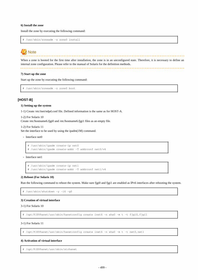
6) Install the zone
Install the zone by executing the following command:
# /usr/sbin/zoneadm -z zone0 install
Note
When a zone is booted for the first time after installation, the zone is in an unconfigured state. Therefore, it is necessary to define aninternal zone configuration. Please refer to the manual of Solaris for the definition methods.
7) Start up the zone
Start up the zone by executing the following command:
# /usr/sbin/zoneadm -z zone0 boot
[HOST-B]
1) Setting up the system
1-1) Create /etc/inet/ndpd.conf file. Defined information is the same as for HOST-A.
1-2) For Solaris 10Create /etc/hostname6.fjgi0 and /etc/hostname6.fjgi1 files as an empty file.
1-2) For Solaris 11Set the interface to be used by using the ipadm(1M) command.
- Interface net0
# /usr/sbin/ipadm create-ip net0# /usr/sbin/ipadm create-addr -T addrconf net0/v6
- Interface net1
# /usr/sbin/ipadm create-ip net1# /usr/sbin/ipadm create-addr -T addrconf net1/v6
2) Reboot (For Solaris 10)
Run the following command to reboot the system. Make sure fjgi0 and fjgi1 are enabled as IPv6 interfaces after rebooting the system.
# /usr/sbin/shutdown -y -i6 -g0
3) Creation of virtual interface
3-1) For Solaris 10
# /opt/FJSVhanet/usr/sbin/hanetconfig create inet6 -n sha0 -m t -t fjgi0,fjgi1
3-1) For Solaris 11
# /opt/FJSVhanet/usr/sbin/hanetconfig create inet6 -n sha0 -m t -t net0,net1
4) Activation of virtual interface
# /opt/FJSVhanet/usr/sbin/strhanet
- 499 -
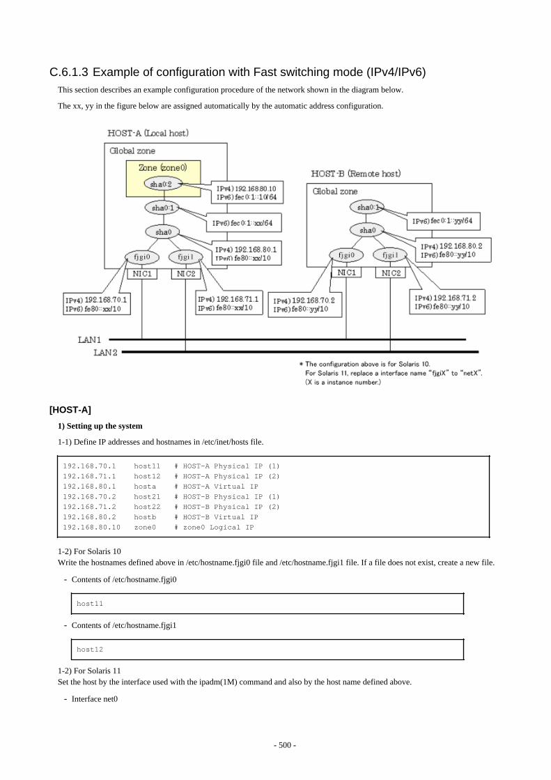
C.6.1.3 Example of configuration with Fast switching mode (IPv4/IPv6)This section describes an example configuration procedure of the network shown in the diagram below.
The xx, yy in the figure below are assigned automatically by the automatic address configuration.
[HOST-A]
1) Setting up the system
1-1) Define IP addresses and hostnames in /etc/inet/hosts file.
192.168.70.1 host11 # HOST-A Physical IP (1)192.168.71.1 host12 # HOST-A Physical IP (2)192.168.80.1 hosta # HOST-A Virtual IP192.168.70.2 host21 # HOST-B Physical IP (1)192.168.71.2 host22 # HOST-B Physical IP (2)192.168.80.2 hostb # HOST-B Virtual IP192.168.80.10 zone0 # zone0 Logical IP
1-2) For Solaris 10Write the hostnames defined above in /etc/hostname.fjgi0 file and /etc/hostname.fjgi1 file. If a file does not exist, create a new file.
- Contents of /etc/hostname.fjgi0
host11
- Contents of /etc/hostname.fjgi1
host12
1-2) For Solaris 11Set the host by the interface used with the ipadm(1M) command and also by the host name defined above.
- Interface net0
- 500 -

# /usr/sbin/ipadm create-ip net0# /usr/sbin/ipadm create-addr -T static -a host11/24 net0/v4
- Interface net1
# /usr/sbin/ipadm create-ip net1# /usr/sbin/ipadm create-addr -T static -a host12/24 net1/v4
1-3) Define the subnet mask in /etc/inet/netmasks file.
192.168.70.0 255.255.255.0192.168.71.0 255.255.255.0192.168.80.0 255.255.255.0
1-4) Create /etc/inet/ndpd.conf file and set the followings:
ifdefault AdvSendAdvertisements true # Every interface sends a router advertisement.prefix fec0:1::0/64 sha0 # sha0 sends Prefix "fec0:1::0/64".
Note
In the Solaris server that runs Fast switching mode, configure two or more router as IPv6 router. If the IPv6 router breaks down, it cannotuse site-local address to communicate. To prevent this, it is recommended to setup at least two IPv6 routers.For details on /etc/inet/ndpd.conf, refer to the Solaris manual.
1-5) For Solaris 10Create /etc/hostname6.fjgi0 and /etc/hostname6.fjgi1 files as an empty file.
1-5) For Solaris 11Set the interface to be used by using the ipadm(1M) command.
- Interface net0
# /usr/sbin/ipadm create-addr -T addrconf net0/v6
- Interface net1
# /usr/sbin/ipadm create-addr -T addrconf net1/v6
2) Reboot (For Solaris 10)
Run the following command to reboot the system. Make sure fjgi0 and fjgi1 are enabled as IPv4/IPv6 interfaces after rebooting the system.
# /usr/sbin/shutdown -y -i6 -g0
3) Creation of virtual interface
3-1) For Solaris 10
# /opt/FJSVhanet/usr/sbin/hanetconfig create -n sha0 -m t -i 192.168.80.1 -t fjgi0,fjgi1# /opt/FJSVhanet/usr/sbin/hanetconfig create inet6 -n sha0 -m t -t fjgi0,fjgi1
3-1) For Solaris 11
# /opt/FJSVhanet/usr/sbin/hanetconfig create -n sha0 -m t -i 192.168.80.1 -t net0,net1# /opt/FJSVhanet/usr/sbin/hanetconfig create inet6 -n sha0 -m t -t net0,net1
- 501 -
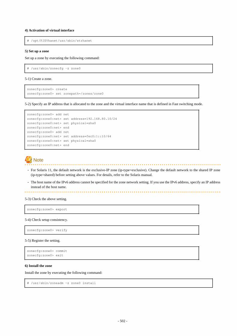
4) Activation of virtual interface
# /opt/FJSVhanet/usr/sbin/strhanet
5) Set up a zone
Set up a zone by executing the following command:
# /usr/sbin/zonecfg -z zone0
5-1) Create a zone.
zonecfg:zone0> createzonecfg:zone0> set zonepath=/zones/zone0
5-2) Specify an IP address that is allocated to the zone and the virtual interface name that is defined in Fast switching mode.
zonecfg:zone0> add netzonecfg:zone0:net> set address=192.168.80.10/24zonecfg:zone0:net> set physical=sha0zonecfg:zone0:net> endzonecfg:zone0> add netzonecfg:zone0:net> set address=fec0:1::10/64zonecfg:zone0:net> set physical=sha0zonecfg:zone0:net> end
Note
- For Solaris 11, the default network is the exclusive-IP zone (ip-type=exclusive). Change the default network to the shared IP zone(ip-type=shared) before setting above values. For details, refer to the Solaris manual.
- The host name of the IPv6 address cannot be specified for the zone network setting. If you use the IPv6 address, specify an IP addressinstead of the host name.
5-3) Check the above setting.
zonecfg:zone0> export
5-4) Check setup consistency.
zonecfg:zone0> verify
5-5) Register the setting.
zonecfg:zone0> commitzonecfg:zone0> exit
6) Install the zone
Install the zone by executing the following command:
# /usr/sbin/zoneadm -z zone0 install
- 502 -

Note
When a zone is booted for the first time after installation, the zone is in an unconfigured state. Therefore, it is necessary to define aninternal zone configuration. Please refer to the manual of Solaris for the definition methods.
7) Start up the zone
Start up the zone by executing the following command:
# /usr/sbin/zoneadm -z zone0 boot
[HOST-B]
1) Setting up the system
1-1) Define IP addresses and hostnames in /etc/inet/hosts file. Defined information is the same as for HOST-A.
1-2) For Solaris 10Write the hostnames defined above in /etc/hostname.fjgi0 file and /etc/hostname.fjgi1 file. If a file does not exist, create a new file.
- Contents of /etc/hostname.fjgi0
host21
- Contents of /etc/hostname.fjgi1
host22
1-2) For Solaris 11Set the host by the interface used with the ipadm(1M) command and also by the host name defined above.
- Interface net0
# /usr/sbin/ipadm create-ip net0# /usr/sbin/ipadm create-addr -T static -a host21/24 net0/v4
- Interface net1
# /usr/sbin/ipadm create-ip net1# /usr/sbin/ipadm create-addr -T static -a host22/24 net1/v4
1-3) Define the subnet mask in /etc/inet/netmasks file. Defined content is same as HOST-A.
1-4) Create /etc/inet/ndpd.conf file. Defined information is the same as for HOST-A.
1-5) For Solaris 10Create /etc/hostname6.fjgi0 and /etc/hostname6.fjgi1 files as an empty file.
1-5) For Solaris 11Set the interface to be used by using the ipadm(1M) command.
- Interface net0
# /usr/sbin/ipadm create-addr -T addrconf net0/v6
- Interface net1
# /usr/sbin/ipadm create-addr -T addrconf net1/v6
2) Reboot (For Slaris 10)
- 503 -
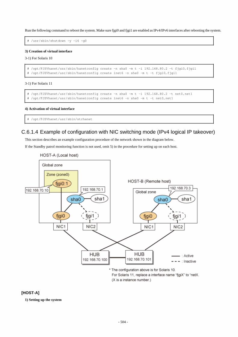
Run the following command to reboot the system. Make sure fjgi0 and fjgi1 are enabled as IPv4/IPv6 interfaces after rebooting the system.
# /usr/sbin/shutdown -y -i6 -g0
3) Creation of virtual interface
3-1) For Solaris 10
# /opt/FJSVhanet/usr/sbin/hanetconfig create -n sha0 -m t -i 192.168.80.2 -t fjgi0,fjgi1# /opt/FJSVhanet/usr/sbin/hanetconfig create inet6 -n sha0 -m t -t fjgi0,fjgi1
3-1) For Solaris 11
# /opt/FJSVhanet/usr/sbin/hanetconfig create -n sha0 -m t -i 192.168.80.2 -t net0,net1# /opt/FJSVhanet/usr/sbin/hanetconfig create inet6 -n sha0 -m t -t net0,net1
4) Activation of virtual interface
# /opt/FJSVhanet/usr/sbin/strhanet
C.6.1.4 Example of configuration with NIC switching mode (IPv4 logical IP takeover)This section describes an example configuration procedure of the network shown in the diagram below.
If the Standby patrol monitoring function is not used, omit 5) in the procedure for setting up on each host.
[HOST-A]
1) Setting up the system
- 504 -
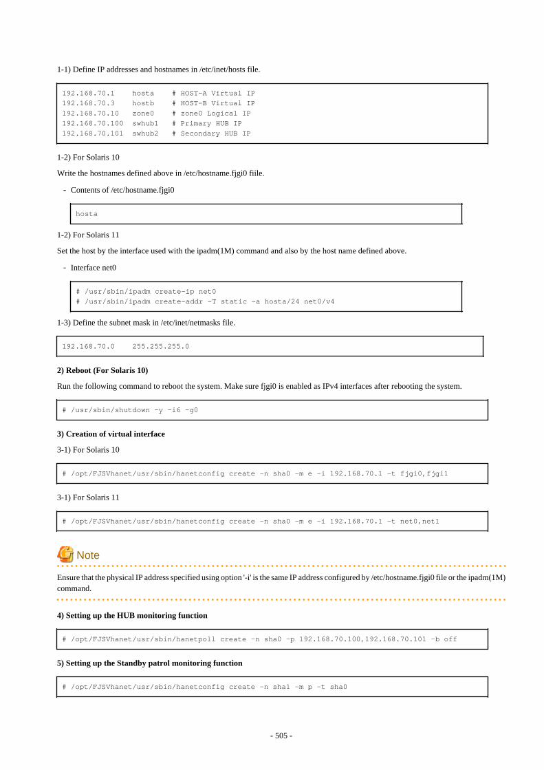
1-1) Define IP addresses and hostnames in /etc/inet/hosts file.
192.168.70.1 hosta # HOST-A Virtual IP192.168.70.3 hostb # HOST-B Virtual IP192.168.70.10 zone0 # zone0 Logical IP192.168.70.100 swhub1 # Primary HUB IP192.168.70.101 swhub2 # Secondary HUB IP
1-2) For Solaris 10
Write the hostnames defined above in /etc/hostname.fjgi0 fiile.
- Contents of /etc/hostname.fjgi0
hosta
1-2) For Solaris 11
Set the host by the interface used with the ipadm(1M) command and also by the host name defined above.
- Interface net0
# /usr/sbin/ipadm create-ip net0# /usr/sbin/ipadm create-addr -T static -a hosta/24 net0/v4
1-3) Define the subnet mask in /etc/inet/netmasks file.
192.168.70.0 255.255.255.0
2) Reboot (For Solaris 10)
Run the following command to reboot the system. Make sure fjgi0 is enabled as IPv4 interfaces after rebooting the system.
# /usr/sbin/shutdown -y -i6 -g0
3) Creation of virtual interface
3-1) For Solaris 10
# /opt/FJSVhanet/usr/sbin/hanetconfig create -n sha0 -m e -i 192.168.70.1 -t fjgi0,fjgi1
3-1) For Solaris 11
# /opt/FJSVhanet/usr/sbin/hanetconfig create -n sha0 -m e -i 192.168.70.1 -t net0,net1
Note
Ensure that the physical IP address specified using option '-i' is the same IP address configured by /etc/hostname.fjgi0 file or the ipadm(1M)command.
4) Setting up the HUB monitoring function
# /opt/FJSVhanet/usr/sbin/hanetpoll create -n sha0 -p 192.168.70.100,192.168.70.101 -b off
5) Setting up the Standby patrol monitoring function
# /opt/FJSVhanet/usr/sbin/hanetconfig create -n sha1 -m p -t sha0
- 505 -
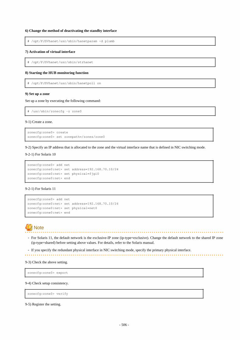
6) Change the method of deactivating the standby interface
# /opt/FJSVhanet/usr/sbin/hanetparam -d plumb
7) Activation of virtual interface
# /opt/FJSVhanet/usr/sbin/strhanet
8) Starting the HUB monitoring function
# /opt/FJSVhanet/usr/sbin/hanetpoll on
9) Set up a zone
Set up a zone by executing the following command:
# /usr/sbin/zonecfg -z zone0
9-1) Create a zone.
zonecfg:zone0> createzonecfg:zone0> set zonepath=/zones/zone0
9-2) Specify an IP address that is allocated to the zone and the virtual interface name that is defined in NIC switching mode.
9-2-1) For Solaris 10
zonecfg:zone0> add netzonecfg:zone0:net> set address=192.168.70.10/24zonecfg:zone0:net> set physical=fjgi0zonecfg:zone0:net> end
9-2-1) For Solaris 11
zonecfg:zone0> add netzonecfg:zone0:net> set address=192.168.70.10/24zonecfg:zone0:net> set physical=net0zonecfg:zone0:net> end
Note
- For Solaris 11, the default network is the exclusive-IP zone (ip-type=exclusive). Change the default network to the shared IP zone(ip-type=shared) before setting above values. For details, refer to the Solaris manual.
- If you specify the redundant physical interface in NIC switching mode, specify the primary physical interface.
9-3) Check the above setting.
zonecfg:zone0> export
9-4) Check setup consistency.
zonecfg:zone0> verify
9-5) Register the setting.
- 506 -
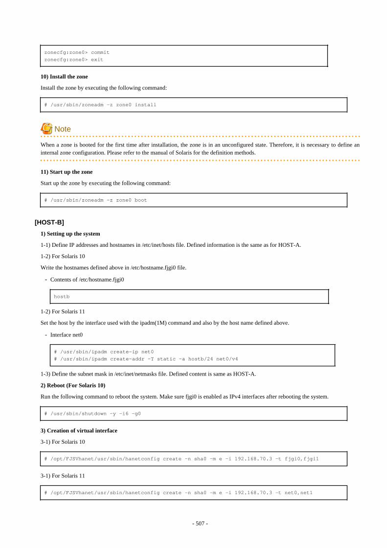
zonecfg:zone0> commitzonecfg:zone0> exit
10) Install the zone
Install the zone by executing the following command:
# /usr/sbin/zoneadm -z zone0 install
Note
When a zone is booted for the first time after installation, the zone is in an unconfigured state. Therefore, it is necessary to define aninternal zone configuration. Please refer to the manual of Solaris for the definition methods.
11) Start up the zone
Start up the zone by executing the following command:
# /usr/sbin/zoneadm -z zone0 boot
[HOST-B]
1) Setting up the system
1-1) Define IP addresses and hostnames in /etc/inet/hosts file. Defined information is the same as for HOST-A.
1-2) For Solaris 10
Write the hostnames defined above in /etc/hostname.fjgi0 file.
- Contents of /etc/hostname.fjgi0
hostb
1-2) For Solaris 11
Set the host by the interface used with the ipadm(1M) command and also by the host name defined above.
- Interface net0
# /usr/sbin/ipadm create-ip net0# /usr/sbin/ipadm create-addr -T static -a hostb/24 net0/v4
1-3) Define the subnet mask in /etc/inet/netmasks file. Defined content is same as HOST-A.
2) Reboot (For Solaris 10)
Run the following command to reboot the system. Make sure fjgi0 is enabled as IPv4 interfaces after rebooting the system.
# /usr/sbin/shutdown -y -i6 -g0
3) Creation of virtual interface
3-1) For Solaris 10
# /opt/FJSVhanet/usr/sbin/hanetconfig create -n sha0 -m e -i 192.168.70.3 -t fjgi0,fjgi1
3-1) For Solaris 11
# /opt/FJSVhanet/usr/sbin/hanetconfig create -n sha0 -m e -i 192.168.70.3 -t net0,net1
- 507 -
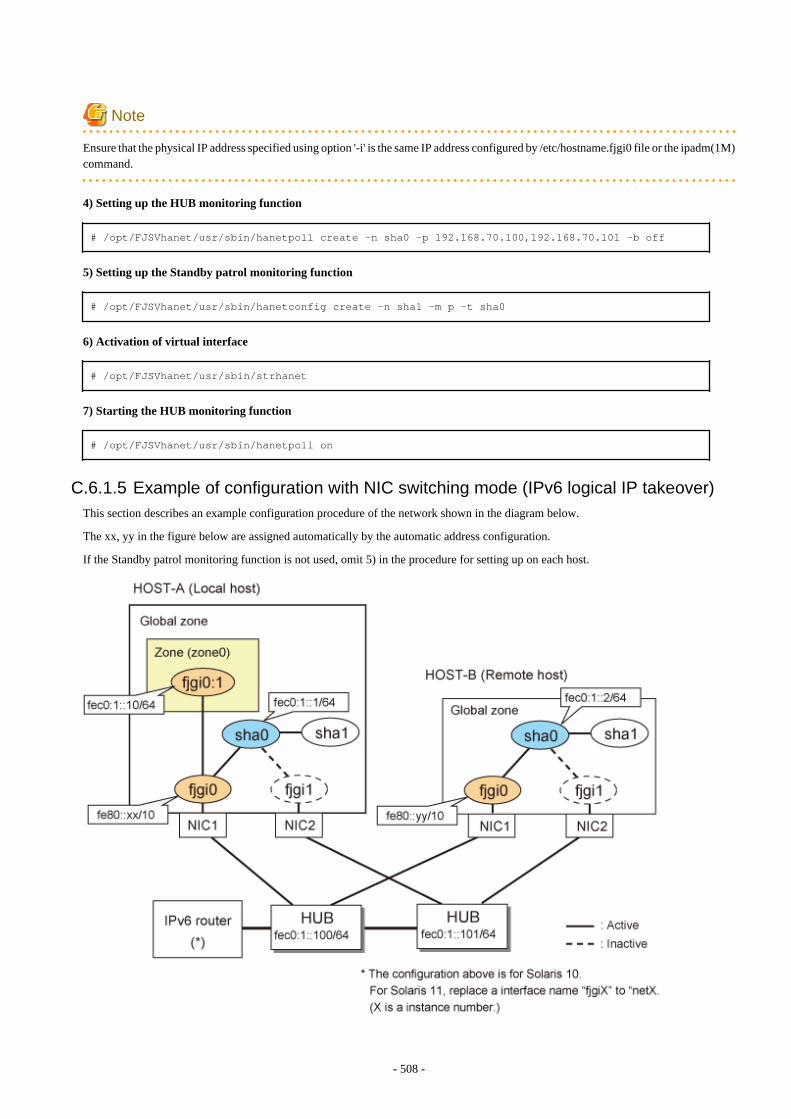
Note
Ensure that the physical IP address specified using option '-i' is the same IP address configured by /etc/hostname.fjgi0 file or the ipadm(1M)command.
4) Setting up the HUB monitoring function
# /opt/FJSVhanet/usr/sbin/hanetpoll create -n sha0 -p 192.168.70.100,192.168.70.101 -b off
5) Setting up the Standby patrol monitoring function
# /opt/FJSVhanet/usr/sbin/hanetconfig create -n sha1 -m p -t sha0
6) Activation of virtual interface
# /opt/FJSVhanet/usr/sbin/strhanet
7) Starting the HUB monitoring function
# /opt/FJSVhanet/usr/sbin/hanetpoll on
C.6.1.5 Example of configuration with NIC switching mode (IPv6 logical IP takeover)This section describes an example configuration procedure of the network shown in the diagram below.
The xx, yy in the figure below are assigned automatically by the automatic address configuration.
If the Standby patrol monitoring function is not used, omit 5) in the procedure for setting up on each host.
- 508 -
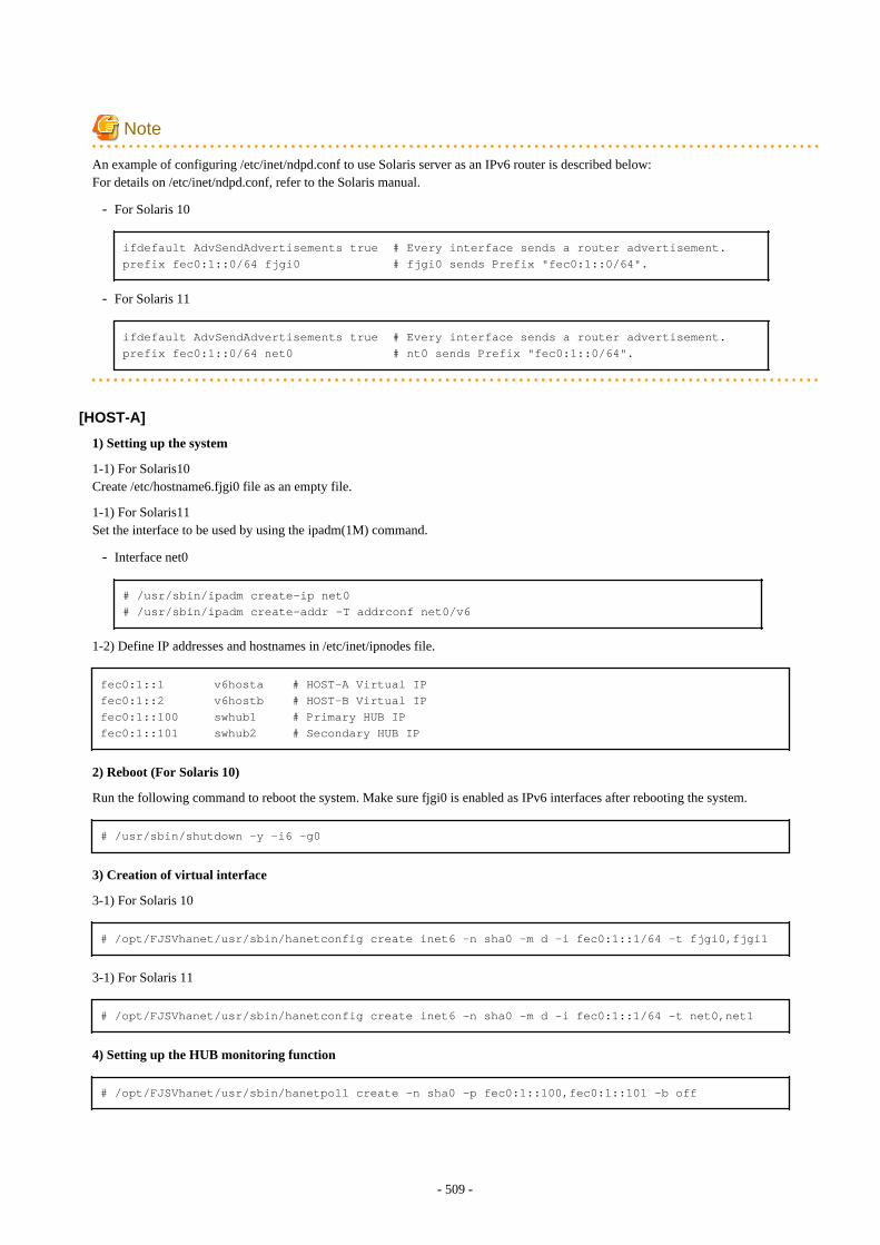
Note
An example of configuring /etc/inet/ndpd.conf to use Solaris server as an IPv6 router is described below:For details on /etc/inet/ndpd.conf, refer to the Solaris manual.
- For Solaris 10
ifdefault AdvSendAdvertisements true # Every interface sends a router advertisement.prefix fec0:1::0/64 fjgi0 # fjgi0 sends Prefix "fec0:1::0/64".
- For Solaris 11
ifdefault AdvSendAdvertisements true # Every interface sends a router advertisement.prefix fec0:1::0/64 net0 # nt0 sends Prefix "fec0:1::0/64".
[HOST-A]
1) Setting up the system
1-1) For Solaris10Create /etc/hostname6.fjgi0 file as an empty file.
1-1) For Solaris11Set the interface to be used by using the ipadm(1M) command.
- Interface net0
# /usr/sbin/ipadm create-ip net0# /usr/sbin/ipadm create-addr -T addrconf net0/v6
1-2) Define IP addresses and hostnames in /etc/inet/ipnodes file.
fec0:1::1 v6hosta # HOST-A Virtual IPfec0:1::2 v6hostb # HOST-B Virtual IPfec0:1::100 swhub1 # Primary HUB IPfec0:1::101 swhub2 # Secondary HUB IP
2) Reboot (For Solaris 10)
Run the following command to reboot the system. Make sure fjgi0 is enabled as IPv6 interfaces after rebooting the system.
# /usr/sbin/shutdown -y -i6 -g0
3) Creation of virtual interface
3-1) For Solaris 10
# /opt/FJSVhanet/usr/sbin/hanetconfig create inet6 -n sha0 -m d -i fec0:1::1/64 -t fjgi0,fjgi1
3-1) For Solaris 11
# /opt/FJSVhanet/usr/sbin/hanetconfig create inet6 -n sha0 -m d -i fec0:1::1/64 -t net0,net1
4) Setting up the HUB monitoring function
# /opt/FJSVhanet/usr/sbin/hanetpoll create -n sha0 -p fec0:1::100,fec0:1::101 -b off
- 509 -
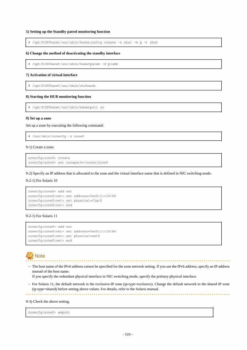
5) Setting up the Standby patrol monitoring function
# /opt/FJSVhanet/usr/sbin/hanetconfig create -n sha1 -m p -t sha0
6) Change the method of deactivating the standby interface
# /opt/FJSVhanet/usr/sbin/hanetparam -d plumb
7) Activation of virtual interface
# /opt/FJSVhanet/usr/sbin/strhanet
8) Starting the HUB monitoring function
# /opt/FJSVhanet/usr/sbin/hanetpoll on
9) Set up a zone
Set up a zone by executing the following command:
# /usr/sbin/zonecfg -z zone0
9-1) Create a zone.
zonecfg:zone0> createzonecfg:zone0> set zonepath=/zones/zone0
9-2) Specify an IP address that is allocated to the zone and the virtual interface name that is defined in NIC switching mode.
9-2-1) For Solaris 10
zonecfg:zone0> add netzonecfg:zone0:net> set address=fec0:1::10/64zonecfg:zone0:net> set physical=fjgi0zonecfg:zone0:net> end
9-2-1) For Solaris 11
zonecfg:zone0> add netzonecfg:zone0:net> set address=fec0:1::10/64zonecfg:zone0:net> set physical=net0zonecfg:zone0:net> end
Note
- The host name of the IPv6 address cannot be specified for the zone network setting. If you use the IPv6 address, specify an IP addressinstead of the host name.If you specify the redundant physical interface in NIC switching mode, specify the primary physical interface.
- For Solaris 11, the default network is the exclusive-IP zone (ip-type=exclusive). Change the default network to the shared IP zone(ip-type=shared) before setting above values. For details, refer to the Solaris manual.
9-3) Check the above setting.
zonecfg:zone0> export
- 510 -
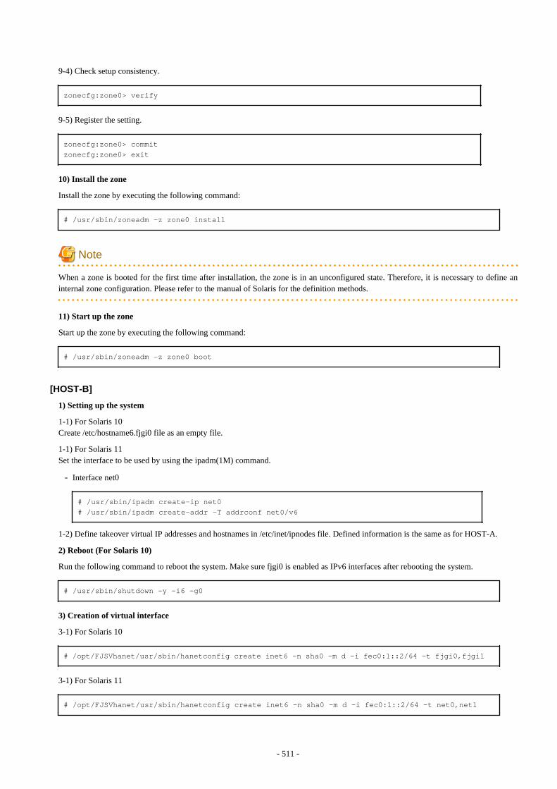
9-4) Check setup consistency.
zonecfg:zone0> verify
9-5) Register the setting.
zonecfg:zone0> commitzonecfg:zone0> exit
10) Install the zone
Install the zone by executing the following command:
# /usr/sbin/zoneadm -z zone0 install
Note
When a zone is booted for the first time after installation, the zone is in an unconfigured state. Therefore, it is necessary to define aninternal zone configuration. Please refer to the manual of Solaris for the definition methods.
11) Start up the zone
Start up the zone by executing the following command:
# /usr/sbin/zoneadm -z zone0 boot
[HOST-B]
1) Setting up the system
1-1) For Solaris 10Create /etc/hostname6.fjgi0 file as an empty file.
1-1) For Solaris 11Set the interface to be used by using the ipadm(1M) command.
- Interface net0
# /usr/sbin/ipadm create-ip net0# /usr/sbin/ipadm create-addr -T addrconf net0/v6
1-2) Define takeover virtual IP addresses and hostnames in /etc/inet/ipnodes file. Defined information is the same as for HOST-A.
2) Reboot (For Solaris 10)
Run the following command to reboot the system. Make sure fjgi0 is enabled as IPv6 interfaces after rebooting the system.
# /usr/sbin/shutdown -y -i6 -g0
3) Creation of virtual interface
3-1) For Solaris 10
# /opt/FJSVhanet/usr/sbin/hanetconfig create inet6 -n sha0 -m d -i fec0:1::2/64 -t fjgi0,fjgi1
3-1) For Solaris 11
# /opt/FJSVhanet/usr/sbin/hanetconfig create inet6 -n sha0 -m d -i fec0:1::2/64 -t net0,net1
- 511 -
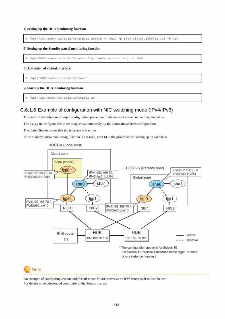
4) Setting up the HUB monitoring function
# /opt/FJSVhanet/usr/sbin/hanetpoll create -n sha0 -p fec0:1::100,fec0:1::101 -b off
5) Setting up the Standby patrol monitoring function
# /opt/FJSVhanet/usr/sbin/hanetconfig create -n sha1 -m p -t sha0
6) Activation of virtual interface
# /opt/FJSVhanet/usr/sbin/strhanet
7) Starting the HUB monitoring function
# /opt/FJSVhanet/usr/sbin/hanetpoll on
C.6.1.6 Example of configuration with NIC switching mode (IPv4/IPv6)This section describes an example configuration procedure of the network shown in the diagram below.
The xx, yy in the figure below are assigned automatically by the automatic address configuration.
The dotted line indicates that the interface is inactive.
If the Standby patrol monitoring function is not used, omit 6) in the procedure for setting up on each host.
Note
An example of configuring /etc/inet/ndpd.conf to use Solaris server as an IPv6 router is described below:For details on /etc/inet/ndpd.conf, refer to the Solaris manual.
- 512 -
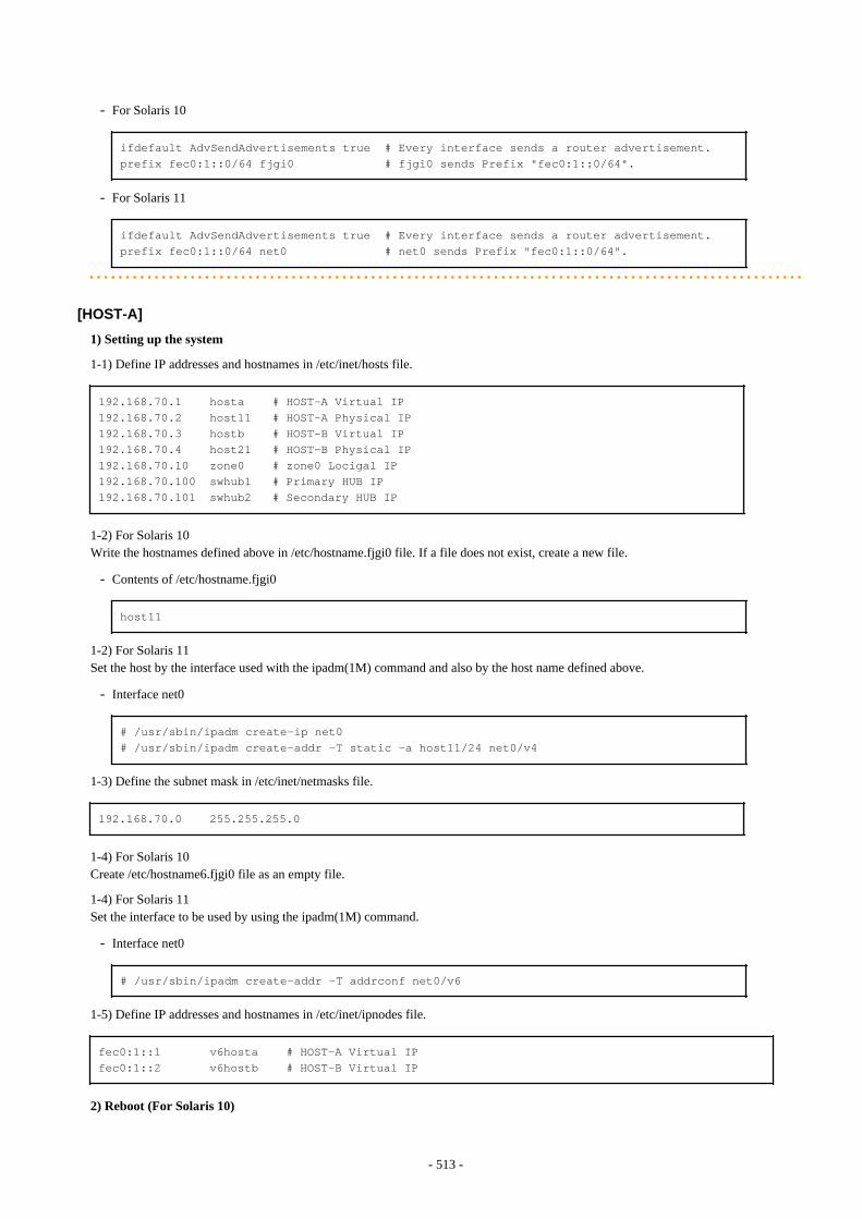
- For Solaris 10
ifdefault AdvSendAdvertisements true # Every interface sends a router advertisement.prefix fec0:1::0/64 fjgi0 # fjgi0 sends Prefix "fec0:1::0/64".
- For Solaris 11
ifdefault AdvSendAdvertisements true # Every interface sends a router advertisement.prefix fec0:1::0/64 net0 # net0 sends Prefix "fec0:1::0/64".
[HOST-A]
1) Setting up the system
1-1) Define IP addresses and hostnames in /etc/inet/hosts file.
192.168.70.1 hosta # HOST-A Virtual IP192.168.70.2 host11 # HOST-A Physical IP192.168.70.3 hostb # HOST-B Virtual IP192.168.70.4 host21 # HOST-B Physical IP192.168.70.10 zone0 # zone0 Locigal IP192.168.70.100 swhub1 # Primary HUB IP192.168.70.101 swhub2 # Secondary HUB IP
1-2) For Solaris 10Write the hostnames defined above in /etc/hostname.fjgi0 file. If a file does not exist, create a new file.
- Contents of /etc/hostname.fjgi0
host11
1-2) For Solaris 11Set the host by the interface used with the ipadm(1M) command and also by the host name defined above.
- Interface net0
# /usr/sbin/ipadm create-ip net0# /usr/sbin/ipadm create-addr -T static -a host11/24 net0/v4
1-3) Define the subnet mask in /etc/inet/netmasks file.
192.168.70.0 255.255.255.0
1-4) For Solaris 10Create /etc/hostname6.fjgi0 file as an empty file.
1-4) For Solaris 11Set the interface to be used by using the ipadm(1M) command.
- Interface net0
# /usr/sbin/ipadm create-addr -T addrconf net0/v6
1-5) Define IP addresses and hostnames in /etc/inet/ipnodes file.
fec0:1::1 v6hosta # HOST-A Virtual IPfec0:1::2 v6hostb # HOST-B Virtual IP
2) Reboot (For Solaris 10)
- 513 -
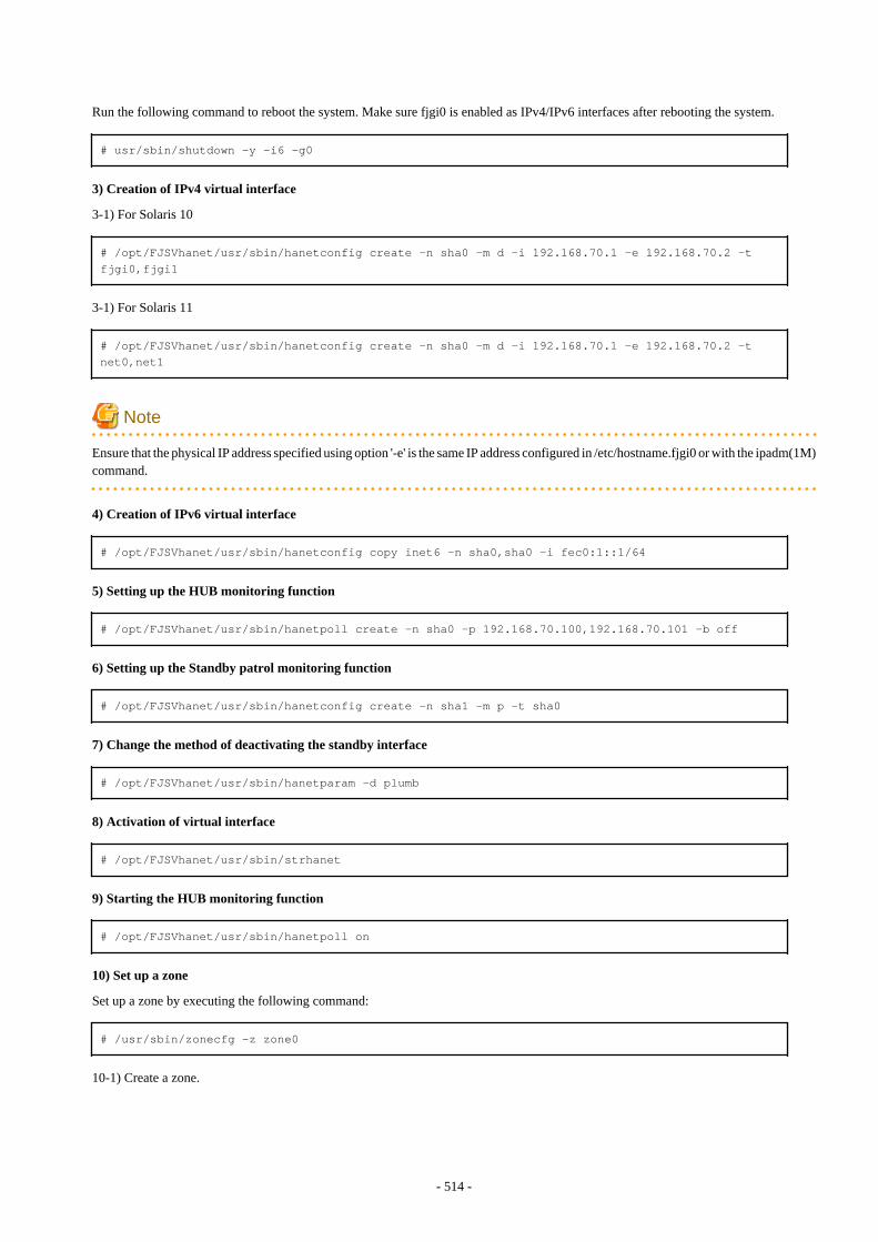
Run the following command to reboot the system. Make sure fjgi0 is enabled as IPv4/IPv6 interfaces after rebooting the system.
# usr/sbin/shutdown -y -i6 -g0
3) Creation of IPv4 virtual interface
3-1) For Solaris 10
# /opt/FJSVhanet/usr/sbin/hanetconfig create -n sha0 -m d -i 192.168.70.1 -e 192.168.70.2 -t fjgi0,fjgi1
3-1) For Solaris 11
# /opt/FJSVhanet/usr/sbin/hanetconfig create -n sha0 -m d -i 192.168.70.1 -e 192.168.70.2 -t net0,net1
Note
Ensure that the physical IP address specified using option '-e' is the same IP address configured in /etc/hostname.fjgi0 or with the ipadm(1M)command.
4) Creation of IPv6 virtual interface
# /opt/FJSVhanet/usr/sbin/hanetconfig copy inet6 -n sha0,sha0 -i fec0:1::1/64
5) Setting up the HUB monitoring function
# /opt/FJSVhanet/usr/sbin/hanetpoll create -n sha0 -p 192.168.70.100,192.168.70.101 -b off
6) Setting up the Standby patrol monitoring function
# /opt/FJSVhanet/usr/sbin/hanetconfig create -n sha1 -m p -t sha0
7) Change the method of deactivating the standby interface
# /opt/FJSVhanet/usr/sbin/hanetparam -d plumb
8) Activation of virtual interface
# /opt/FJSVhanet/usr/sbin/strhanet
9) Starting the HUB monitoring function
# /opt/FJSVhanet/usr/sbin/hanetpoll on
10) Set up a zone
Set up a zone by executing the following command:
# /usr/sbin/zonecfg -z zone0
10-1) Create a zone.
- 514 -
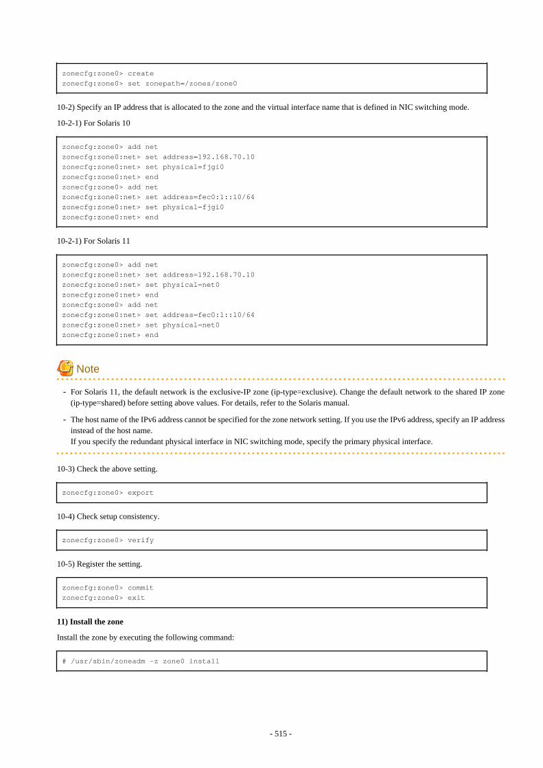
zonecfg:zone0> createzonecfg:zone0> set zonepath=/zones/zone0
10-2) Specify an IP address that is allocated to the zone and the virtual interface name that is defined in NIC switching mode.
10-2-1) For Solaris 10
zonecfg:zone0> add netzonecfg:zone0:net> set address=192.168.70.10zonecfg:zone0:net> set physical=fjgi0zonecfg:zone0:net> endzonecfg:zone0> add netzonecfg:zone0:net> set address=fec0:1::10/64zonecfg:zone0:net> set physical=fjgi0zonecfg:zone0:net> end
10-2-1) For Solaris 11
zonecfg:zone0> add netzonecfg:zone0:net> set address=192.168.70.10zonecfg:zone0:net> set physical=net0zonecfg:zone0:net> endzonecfg:zone0> add netzonecfg:zone0:net> set address=fec0:1::10/64zonecfg:zone0:net> set physical=net0zonecfg:zone0:net> end
Note
- For Solaris 11, the default network is the exclusive-IP zone (ip-type=exclusive). Change the default network to the shared IP zone(ip-type=shared) before setting above values. For details, refer to the Solaris manual.
- The host name of the IPv6 address cannot be specified for the zone network setting. If you use the IPv6 address, specify an IP addressinstead of the host name.If you specify the redundant physical interface in NIC switching mode, specify the primary physical interface.
10-3) Check the above setting.
zonecfg:zone0> export
10-4) Check setup consistency.
zonecfg:zone0> verify
10-5) Register the setting.
zonecfg:zone0> commitzonecfg:zone0> exit
11) Install the zone
Install the zone by executing the following command:
# /usr/sbin/zoneadm -z zone0 install
- 515 -

Note
When a zone is booted for the first time after installation, the zone is in an unconfigured state. Therefore, it is necessary to define aninternal zone configuration. Please refer to the manual of Solaris for the definition methods.
12) Start up the zone
Start up the zone by executing the following command:
# /usr/sbin/zoneadm -z zone0 boot
[HOST-B]
1) Setting up the system
1-1) Define IP addresses and hostnames in /etc/inet/hosts file. Defined information is the same as for HOST-A.
1-2) For Solaris 10Write the hostnames defined above in /etc/hostname.fjgi0 file. If a file does not exist, create a new file.
- Contents of /etc/hostname.fjgi0
host21
1-2) For Solaris 11Set the host by the interface used with the ipadm(1M) command and also by the host name defined above.
- Interface net0
# /usr/sbin/ipadm create-ip net0# /usr/sbin/ipadm create-addr -T static -a host21/24 net0/v4
1-3) Define the subnet mask in /etc/inet/netmasks file. Defined content is same as HOST-A.
1-4) For Solaris 10Create /etc/hostname6.fjgi0 file as an empty file.
1-4) For Solaris 11Set the interface to be used by using the ipadm(1M) command.
- Interface net0
# /usr/sbin/ipadm create-addr -T addrconf net0/v6
1-5) Define IP addresses and hostnames in /etc/inet/ipnodes file. Defined content is same as HOST-A.
2) Reboot (For Solaris 10)
Run the following command to reboot the system. Make sure fjgi0 is enabled as IPv4/IPv6 interfaces after rebooting the system.
# /usr/sbin/shutdown -y -i6 -g0
3) Creation of IPv4 virtual interface
3-1) For Solaris 10
# /opt/FJSVhanet/usr/sbin/hanetconfig create -n sha0 -m d -i 192.168.70.3 -e 192.168.70.4 -t fjgi0,fjgi1
3-1) For Solaris 11
- 516 -
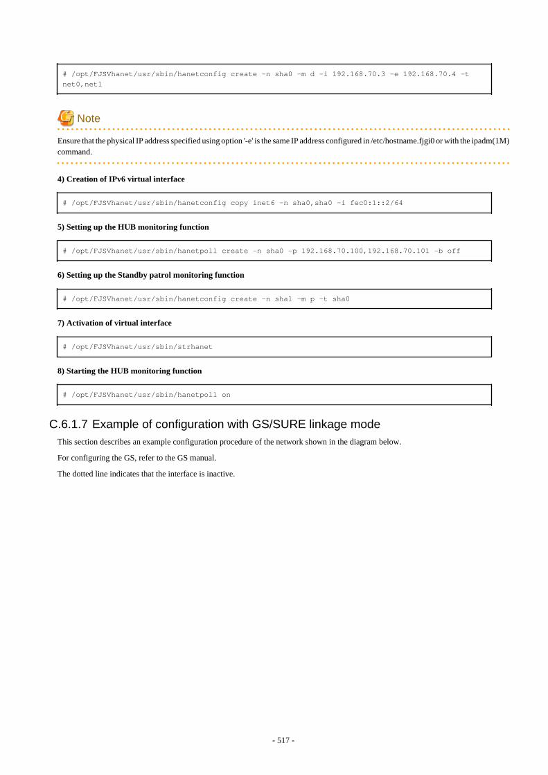
# /opt/FJSVhanet/usr/sbin/hanetconfig create -n sha0 -m d -i 192.168.70.3 -e 192.168.70.4 -t net0,net1
Note
Ensure that the physical IP address specified using option '-e' is the same IP address configured in /etc/hostname.fjgi0 or with the ipadm(1M)command.
4) Creation of IPv6 virtual interface
# /opt/FJSVhanet/usr/sbin/hanetconfig copy inet6 -n sha0,sha0 -i fec0:1::2/64
5) Setting up the HUB monitoring function
# /opt/FJSVhanet/usr/sbin/hanetpoll create -n sha0 -p 192.168.70.100,192.168.70.101 -b off
6) Setting up the Standby patrol monitoring function
# /opt/FJSVhanet/usr/sbin/hanetconfig create -n sha1 -m p -t sha0
7) Activation of virtual interface
# /opt/FJSVhanet/usr/sbin/strhanet
8) Starting the HUB monitoring function
# /opt/FJSVhanet/usr/sbin/hanetpoll on
C.6.1.7 Example of configuration with GS/SURE linkage modeThis section describes an example configuration procedure of the network shown in the diagram below.
For configuring the GS, refer to the GS manual.
The dotted line indicates that the interface is inactive.
- 517 -
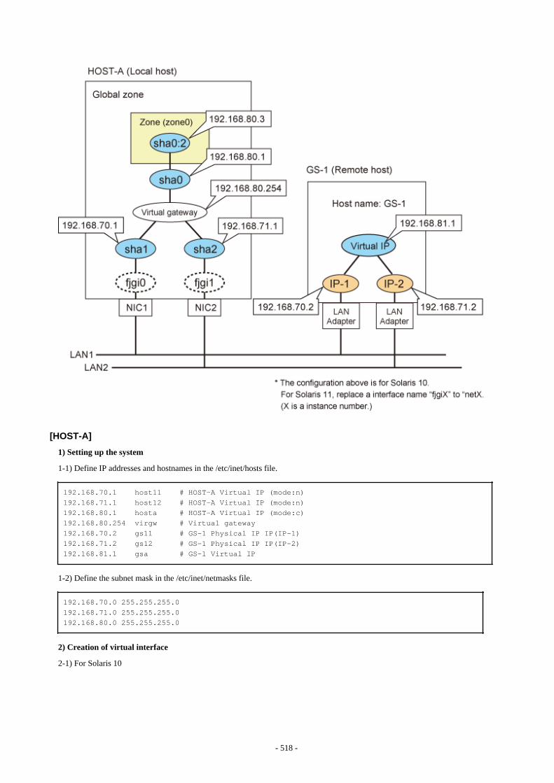
[HOST-A]
1) Setting up the system
1-1) Define IP addresses and hostnames in the /etc/inet/hosts file.
192.168.70.1 host11 # HOST-A Virtual IP (mode:n)192.168.71.1 host12 # HOST-A Virtual IP (mode:n)192.168.80.1 hosta # HOST-A Virtual IP (mode:c)192.168.80.254 virgw # Virtual gateway192.168.70.2 gs11 # GS-1 Physical IP IP(IP-1)192.168.71.2 gs12 # GS-1 Physical IP IP(IP-2)192.168.81.1 gsa # GS-1 Virtual IP
1-2) Define the subnet mask in the /etc/inet/netmasks file.
192.168.70.0 255.255.255.0192.168.71.0 255.255.255.0192.168.80.0 255.255.255.0
2) Creation of virtual interface
2-1) For Solaris 10
- 518 -
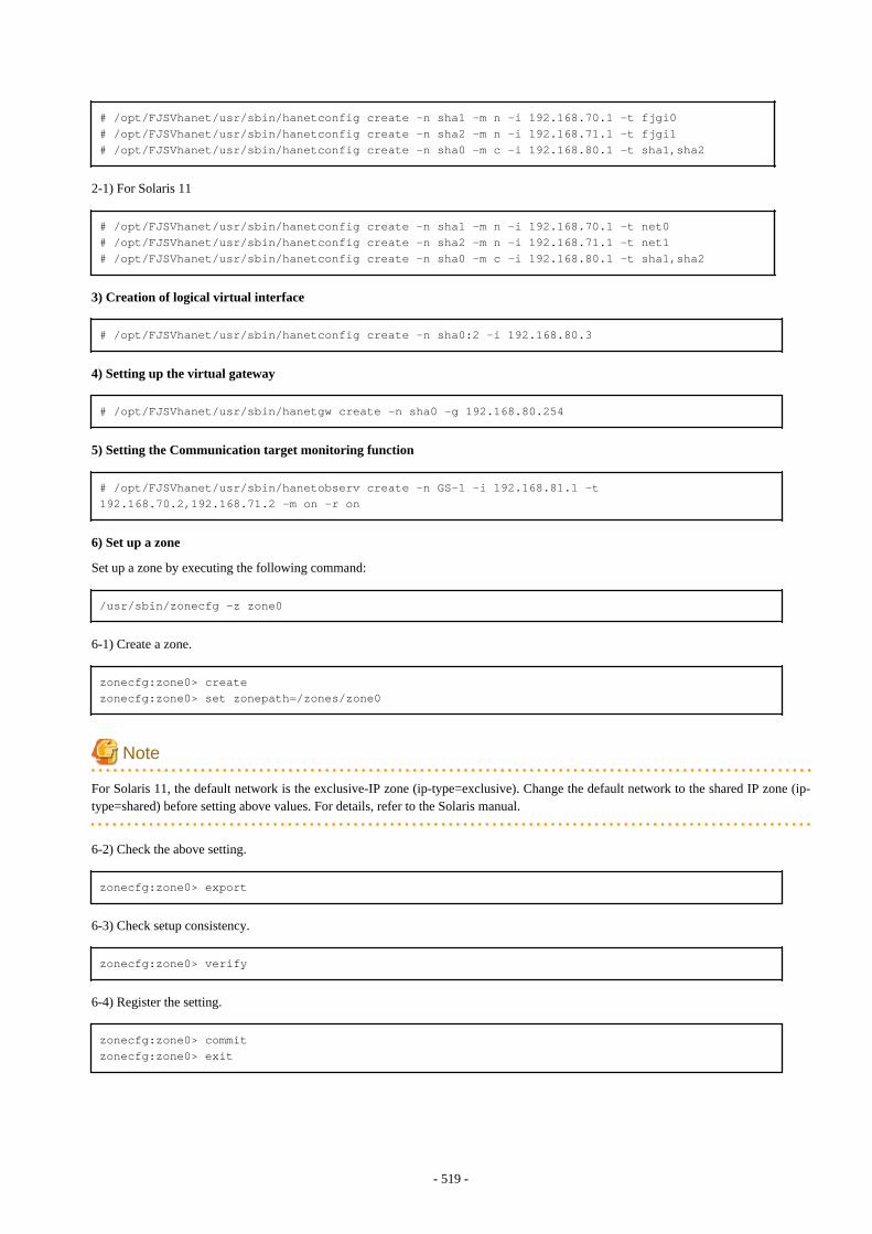
# /opt/FJSVhanet/usr/sbin/hanetconfig create -n sha1 -m n -i 192.168.70.1 -t fjgi0# /opt/FJSVhanet/usr/sbin/hanetconfig create -n sha2 -m n -i 192.168.71.1 -t fjgi1# /opt/FJSVhanet/usr/sbin/hanetconfig create -n sha0 -m c -i 192.168.80.1 -t sha1,sha2
2-1) For Solaris 11
# /opt/FJSVhanet/usr/sbin/hanetconfig create -n sha1 -m n -i 192.168.70.1 -t net0# /opt/FJSVhanet/usr/sbin/hanetconfig create -n sha2 -m n -i 192.168.71.1 -t net1# /opt/FJSVhanet/usr/sbin/hanetconfig create -n sha0 -m c -i 192.168.80.1 -t sha1,sha2
3) Creation of logical virtual interface
# /opt/FJSVhanet/usr/sbin/hanetconfig create -n sha0:2 -i 192.168.80.3
4) Setting up the virtual gateway
# /opt/FJSVhanet/usr/sbin/hanetgw create -n sha0 -g 192.168.80.254
5) Setting the Communication target monitoring function
# /opt/FJSVhanet/usr/sbin/hanetobserv create -n GS-1 -i 192.168.81.1 -t 192.168.70.2,192.168.71.2 -m on -r on
6) Set up a zone
Set up a zone by executing the following command:
/usr/sbin/zonecfg -z zone0
6-1) Create a zone.
zonecfg:zone0> createzonecfg:zone0> set zonepath=/zones/zone0
Note
For Solaris 11, the default network is the exclusive-IP zone (ip-type=exclusive). Change the default network to the shared IP zone (ip-type=shared) before setting above values. For details, refer to the Solaris manual.
6-2) Check the above setting.
zonecfg:zone0> export
6-3) Check setup consistency.
zonecfg:zone0> verify
6-4) Register the setting.
zonecfg:zone0> commitzonecfg:zone0> exit
- 519 -
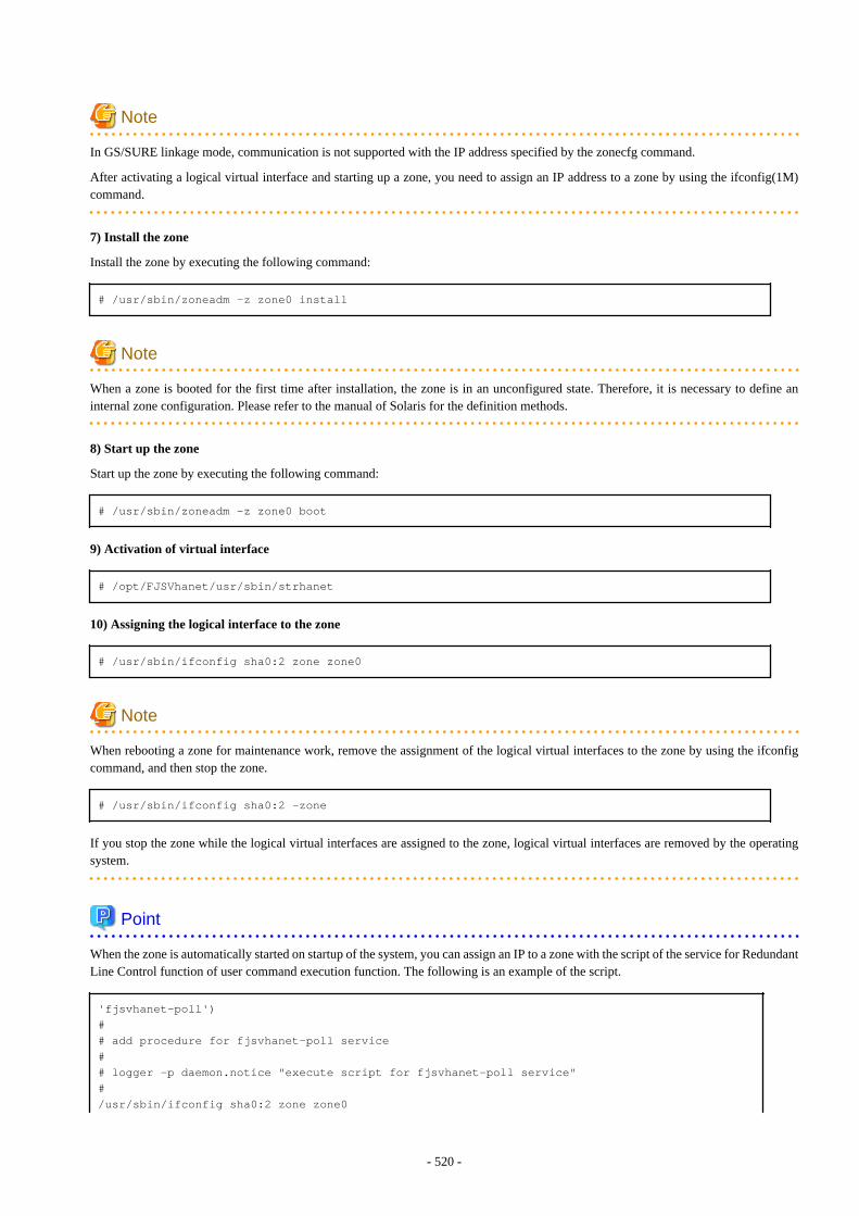
Note
In GS/SURE linkage mode, communication is not supported with the IP address specified by the zonecfg command.
After activating a logical virtual interface and starting up a zone, you need to assign an IP address to a zone by using the ifconfig(1M)command.
7) Install the zone
Install the zone by executing the following command:
# /usr/sbin/zoneadm -z zone0 install
Note
When a zone is booted for the first time after installation, the zone is in an unconfigured state. Therefore, it is necessary to define aninternal zone configuration. Please refer to the manual of Solaris for the definition methods.
8) Start up the zone
Start up the zone by executing the following command:
# /usr/sbin/zoneadm -z zone0 boot
9) Activation of virtual interface
# /opt/FJSVhanet/usr/sbin/strhanet
10) Assigning the logical interface to the zone
# /usr/sbin/ifconfig sha0:2 zone zone0
Note
When rebooting a zone for maintenance work, remove the assignment of the logical virtual interfaces to the zone by using the ifconfigcommand, and then stop the zone.
# /usr/sbin/ifconfig sha0:2 -zone
If you stop the zone while the logical virtual interfaces are assigned to the zone, logical virtual interfaces are removed by the operatingsystem.
Point
When the zone is automatically started on startup of the system, you can assign an IP to a zone with the script of the service for RedundantLine Control function of user command execution function. The following is an example of the script.
'fjsvhanet-poll')## add procedure for fjsvhanet-poll service## logger -p daemon.notice "execute script for fjsvhanet-poll service"#/usr/sbin/ifconfig sha0:2 zone zone0
- 520 -
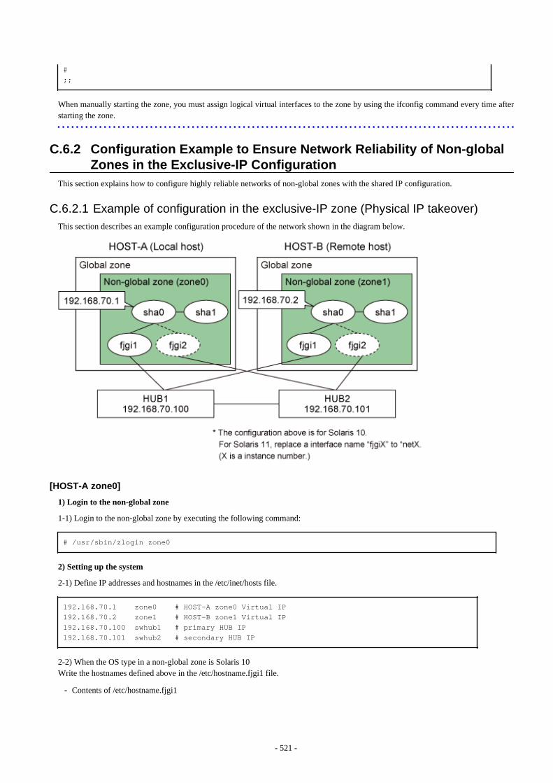
#;;
When manually starting the zone, you must assign logical virtual interfaces to the zone by using the ifconfig command every time afterstarting the zone.
C.6.2 Configuration Example to Ensure Network Reliability of Non-globalZones in the Exclusive-IP Configuration
This section explains how to configure highly reliable networks of non-global zones with the shared IP configuration.
C.6.2.1 Example of configuration in the exclusive-IP zone (Physical IP takeover)This section describes an example configuration procedure of the network shown in the diagram below.
[HOST-A zone0]
1) Login to the non-global zone
1-1) Login to the non-global zone by executing the following command:
# /usr/sbin/zlogin zone0
2) Setting up the system
2-1) Define IP addresses and hostnames in the /etc/inet/hosts file.
192.168.70.1 zone0 # HOST-A zone0 Virtual IP 192.168.70.2 zone1 # HOST-B zone1 Virtual IP 192.168.70.100 swhub1 # primary HUB IP192.168.70.101 swhub2 # secondary HUB IP
2-2) When the OS type in a non-global zone is Solaris 10Write the hostnames defined above in the /etc/hostname.fjgi1 file.
- Contents of /etc/hostname.fjgi1
- 521 -

zone0
2-2) When the OS type in a non-global zone is Solaris 11Set the host by the interface used with the ipadm(1M) command and also by the host name defined above.
- Interface net1
# /usr/sbin/ipadm create-ip net1# /usr/sbin/ipadm create-addr -T static -a zone0/24 net1/v4
2-3) Define the subnet mask in the /etc/inet/netmasks file.
192.168.70.0 255.255.255.0
3) Reboot (For Solaris 10)
Run the following command to reboot the non-global zone. Run this command from the non-global zone. Make sure fjgi1 is enabled byrunning the ifconfig command after rebooting the system.
# /usr/sbin/shutdown -y -i6 -g0
4) Creation of virtual interface
4-1) For Solaris 10
# /opt/FJSVhanet/usr/sbin/hanetconfig create -n sha0 -m e -i 192.168.70.1 -t fjgi1,fjgi2
4-1) For Solaris 11
# /opt/FJSVhanet/usr/sbin/hanetconfig create -n sha0 -m e -i 192.168.70.1 -t net1,net2
Note
Ensure that the physical IP address specified using option '-i' is the same IP address configured in /etc/hostname.fjgi1 or with the ipadm(1M)command.
5) Setting up the HUB monitoring function
# /opt/FJSVhanet/usr/sbin/hanetpoll create -n sha0 -p 192.168.70.100,192.168.70.101 -b off
6) Setting up the Standby patrol monitoring function
# /opt/FJSVhanet/usr/sbin/hanetconfig create -n sha1 -m p -t sha0
7) Activation of virtual interface
# /opt/FJSVhanet/usr/sbin/strhanet
8) Starting the HUB monitoring function
# /opt/FJSVhanet/usr/sbin/hanetpoll on
[HOST-B zone1]
1) Login to the non-global zone
- 522 -

1-1) Login to the non-global zone by executing the following command:
# /usr/sbin/zlogin zone1
2) Setting up the system
2-1) Define IP addresses and hostnames in the /etc/inet/hosts file. Defined information is the same as for HOST-A zone0.2-2) When the OS type in a non-global zone is Solaris 10Write the hostnames defined above in the /etc/hostname.fjgi1 file.
- Contents of /etc/hostname.fjgi1
zone1
2-2) When the OS type in a non-global zone is Solaris 11Set the host by the interface used with the ipadm(1M) command and also by the host name defined above.
- Interface net1
# /usr/sbin/ipadm create-ip net1# /usr/sbin/ipadm create-addr -T static -a zone1/24 net1/v4
2-3) Define the subnet mask in the /etc/inet/netmasks file. Defined content is same as for HOST-A zone0.
3) Reboot (For Solaris 10)
Run the following command to reboot the non-global zone. Run this command from the non-global zone. Make sure fjgi1 is enabled byrunning the ifconfig command after rebooting the system.
# /usr/sbin/shutdown -y -i6 -g0
4) Creation of virtual interface
4-1) For Solaris 10
# /opt/FJSVhanet/usr/sbin/hanetconfig create -n sha0 -m e -i 192.168.70.2 -t fjgi1,fjgi2
4-1) For Solaris 11
# /opt/FJSVhanet/usr/sbin/hanetconfig create -n sha0 -m e -i 192.168.70.2 -t net1,net2
Note
Ensure that the physical IP address specified using option '-i' is the same IP address configured in /etc/hostname.fjgi1 or with the ipadm(1M)command.
5) Setting up the HUB monitoring function
# /opt/FJSVhanet/usr/sbin/hanetpoll create -n sha0 -p 192.168.70.100,192.168.70.101 -b off
6) Setting up the Standby patrol monitoring function
# /opt/FJSVhanet/usr/sbin/hanetconfig create -n sha1 -m p -t sha0
7) Activation of virtual interface
# /opt/FJSVhanet/usr/sbin/strhanet
- 523 -
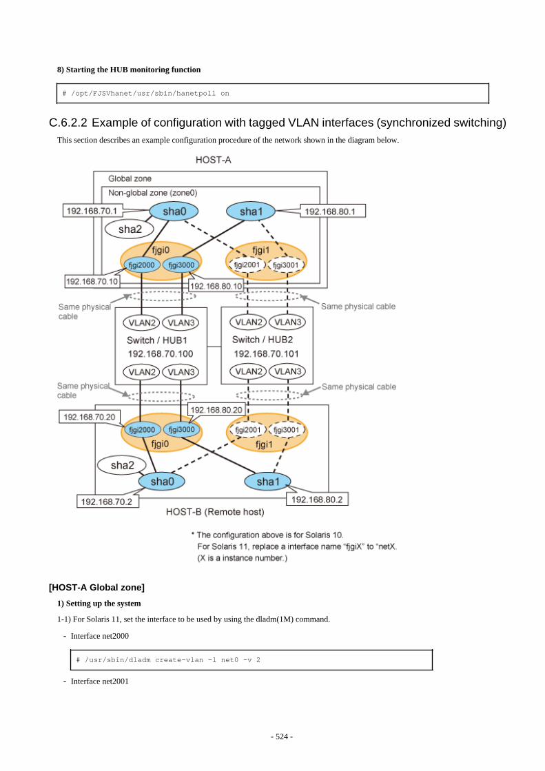
8) Starting the HUB monitoring function
# /opt/FJSVhanet/usr/sbin/hanetpoll on
C.6.2.2 Example of configuration with tagged VLAN interfaces (synchronized switching)This section describes an example configuration procedure of the network shown in the diagram below.
[HOST-A Global zone]
1) Setting up the system
1-1) For Solaris 11, set the interface to be used by using the dladm(1M) command.
- Interface net2000
# /usr/sbin/dladm create-vlan -l net0 -v 2
- Interface net2001
- 524 -
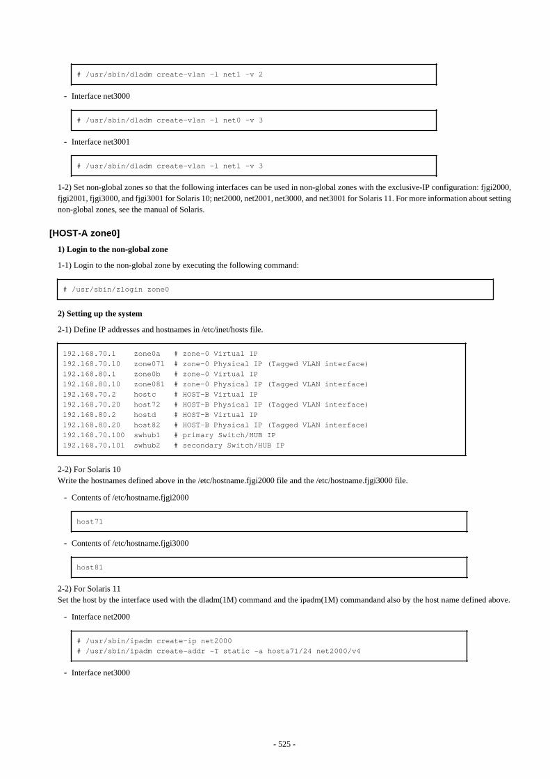
# /usr/sbin/dladm create-vlan -l net1 -v 2
- Interface net3000
# /usr/sbin/dladm create-vlan -l net0 -v 3
- Interface net3001
# /usr/sbin/dladm create-vlan -l net1 -v 3
1-2) Set non-global zones so that the following interfaces can be used in non-global zones with the exclusive-IP configuration: fjgi2000,fjgi2001, fjgi3000, and fjgi3001 for Solaris 10; net2000, net2001, net3000, and net3001 for Solaris 11. For more information about settingnon-global zones, see the manual of Solaris.
[HOST-A zone0]
1) Login to the non-global zone
1-1) Login to the non-global zone by executing the following command:
# /usr/sbin/zlogin zone0
2) Setting up the system
2-1) Define IP addresses and hostnames in /etc/inet/hosts file.
192.168.70.1 zone0a # zone-0 Virtual IP192.168.70.10 zone071 # zone-0 Physical IP (Tagged VLAN interface)192.168.80.1 zone0b # zone-0 Virtual IP192.168.80.10 zone081 # zone-0 Physical IP (Tagged VLAN interface)192.168.70.2 hostc # HOST-B Virtual IP192.168.70.20 host72 # HOST-B Physical IP (Tagged VLAN interface)192.168.80.2 hostd # HOST-B Virtual IP192.168.80.20 host82 # HOST-B Physical IP (Tagged VLAN interface)192.168.70.100 swhub1 # primary Switch/HUB IP192.168.70.101 swhub2 # secondary Switch/HUB IP
2-2) For Solaris 10Write the hostnames defined above in the /etc/hostname.fjgi2000 file and the /etc/hostname.fjgi3000 file.
- Contents of /etc/hostname.fjgi2000
host71
- Contents of /etc/hostname.fjgi3000
host81
2-2) For Solaris 11Set the host by the interface used with the dladm(1M) command and the ipadm(1M) commandand also by the host name defined above.
- Interface net2000
# /usr/sbin/ipadm create-ip net2000# /usr/sbin/ipadm create-addr -T static -a hosta71/24 net2000/v4
- Interface net3000
- 525 -
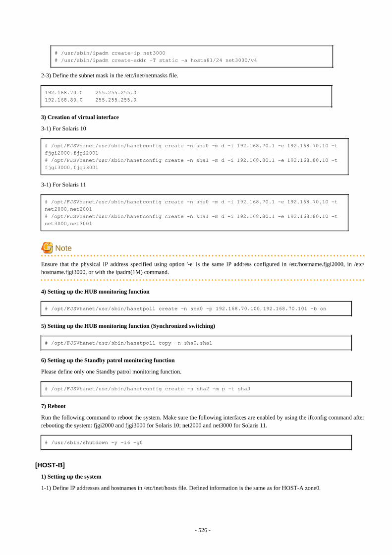
# /usr/sbin/ipadm create-ip net3000# /usr/sbin/ipadm create-addr -T static -a hosta81/24 net3000/v4
2-3) Define the subnet mask in the /etc/inet/netmasks file.
192.168.70.0 255.255.255.0192.168.80.0 255.255.255.0
3) Creation of virtual interface
3-1) For Solaris 10
# /opt/FJSVhanet/usr/sbin/hanetconfig create -n sha0 -m d -i 192.168.70.1 -e 192.168.70.10 -t fjgi2000,fjgi2001# /opt/FJSVhanet/usr/sbin/hanetconfig create -n sha1 -m d -i 192.168.80.1 -e 192.168.80.10 -t fjgi3000,fjgi3001
3-1) For Solaris 11
# /opt/FJSVhanet/usr/sbin/hanetconfig create -n sha0 -m d -i 192.168.70.1 -e 192.168.70.10 -t net2000,net2001# /opt/FJSVhanet/usr/sbin/hanetconfig create -n sha1 -m d -i 192.168.80.1 -e 192.168.80.10 -t net3000,net3001
Note
Ensure that the physical IP address specified using option '-e' is the same IP address configured in /etc/hostname.fjgi2000, in /etc/hostname.fjgi3000, or with the ipadm(1M) command.
4) Setting up the HUB monitoring function
# /opt/FJSVhanet/usr/sbin/hanetpoll create -n sha0 -p 192.168.70.100,192.168.70.101 -b on
5) Setting up the HUB monitoring function (Synchronized switching)
# /opt/FJSVhanet/usr/sbin/hanetpoll copy -n sha0,sha1
6) Setting up the Standby patrol monitoring function
Please define only one Standby patrol monitoring function.
# /opt/FJSVhanet/usr/sbin/hanetconfig create -n sha2 -m p -t sha0
7) Reboot
Run the following command to reboot the system. Make sure the following interfaces are enabled by using the ifconfig command afterrebooting the system: fjgi2000 and fjgi3000 for Solaris 10; net2000 and net3000 for Solaris 11.
# /usr/sbin/shutdown -y -i6 -g0
[HOST-B]
1) Setting up the system
1-1) Define IP addresses and hostnames in /etc/inet/hosts file. Defined information is the same as for HOST-A zone0.
- 526 -
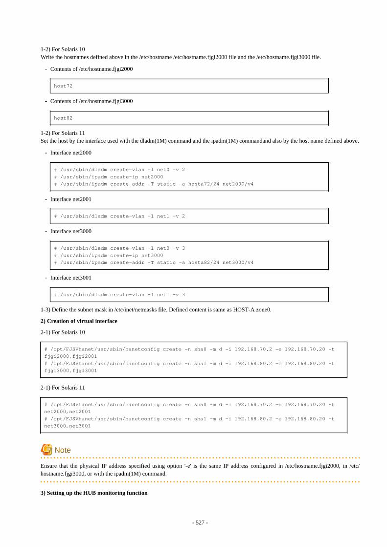
1-2) For Solaris 10Write the hostnames defined above in the /etc/hostname /etc/hostname.fjgi2000 file and the /etc/hostname.fjgi3000 file.
- Contents of /etc/hostname.fjgi2000
host72
- Contents of /etc/hostname.fjgi3000
host82
1-2) For Solaris 11Set the host by the interface used with the dladm(1M) command and the ipadm(1M) commandand also by the host name defined above.
- Interface net2000
# /usr/sbin/dladm create-vlan -l net0 -v 2# /usr/sbin/ipadm create-ip net2000# /usr/sbin/ipadm create-addr -T static -a hosta72/24 net2000/v4
- Interface net2001
# /usr/sbin/dladm create-vlan -l net1 -v 2
- Interface net3000
# /usr/sbin/dladm create-vlan -l net0 -v 3# /usr/sbin/ipadm create-ip net3000# /usr/sbin/ipadm create-addr -T static -a hosta82/24 net3000/v4
- Interface net3001
# /usr/sbin/dladm create-vlan -l net1 -v 3
1-3) Define the subnet mask in /etc/inet/netmasks file. Defined content is same as HOST-A zone0.
2) Creation of virtual interface
2-1) For Solaris 10
# /opt/FJSVhanet/usr/sbin/hanetconfig create -n sha0 -m d -i 192.168.70.2 -e 192.168.70.20 -t fjgi2000,fjgi2001# /opt/FJSVhanet/usr/sbin/hanetconfig create -n sha1 -m d -i 192.168.80.2 -e 192.168.80.20 -t fjgi3000,fjgi3001
2-1) For Solaris 11
# /opt/FJSVhanet/usr/sbin/hanetconfig create -n sha0 -m d -i 192.168.70.2 -e 192.168.70.20 -t net2000,net2001# /opt/FJSVhanet/usr/sbin/hanetconfig create -n sha1 -m d -i 192.168.80.2 -e 192.168.80.20 -t net3000,net3001
Note
Ensure that the physical IP address specified using option '-e' is the same IP address configured in /etc/hostname.fjgi2000, in /etc/hostname.fjgi3000, or with the ipadm(1M) command.
3) Setting up the HUB monitoring function
- 527 -
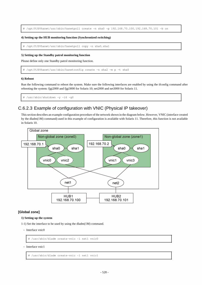
# /opt/FJSVhanet/usr/sbin/hanetpoll create -n sha0 -p 192.168.70.100,192.168.70.101 -b on
4) Setting up the HUB monitoring function (Synchronized switching)
# /opt/FJSVhanet/usr/sbin/hanetpoll copy -n sha0,sha1
5) Setting up the Standby patrol monitoring function
Please define only one Standby patrol monitoring function.
# /opt/FJSVhanet/usr/sbin/hanetconfig create -n sha2 -m p -t sha0
6) Reboot
Run the following command to reboot the system. Make sure the following interfaces are enabled by using the ifconfig command afterrebooting the system: fjgi2000 and fjgi3000 for Solaris 10; net2000 and net3000 for Solaris 11.
# /usr/sbin/shutdown -y -i6 -g0
C.6.2.3 Example of configuration with VNIC (Physical IP takeover)This section describes an example configuration procedure of the network shown in the diagram below. However, VNIC (interface createdby the dladm(1M) command) used in this example of configuration is available with Solaris 11. Therefore, this function is not availablein Solaris 10.
[Global zone]
1) Setting up the system
1-1) Set the interface to be used by using the dladm(1M) command.
- Interface vnic0
# /usr/sbin/dladm create-vnic -l net1 vnic0
- Interface vnic1
# /usr/sbin/dladm create-vnic -l net1 vnic1
- 528 -
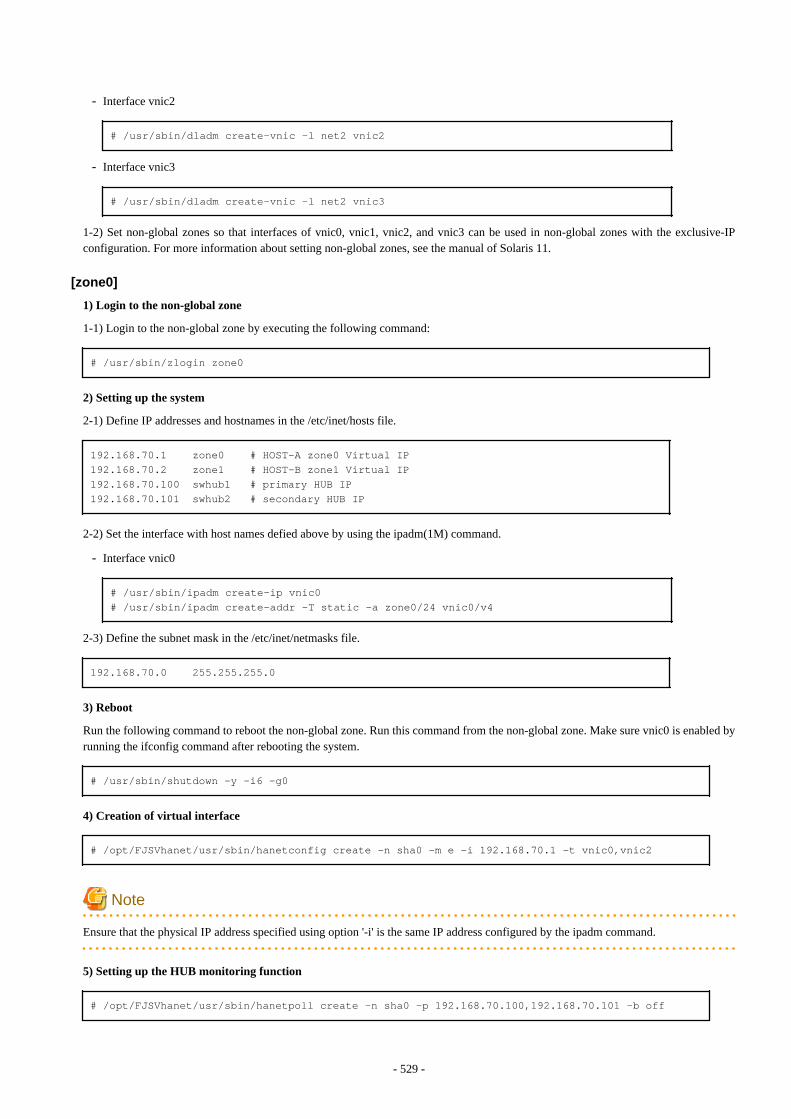
- Interface vnic2
# /usr/sbin/dladm create-vnic -l net2 vnic2
- Interface vnic3
# /usr/sbin/dladm create-vnic -l net2 vnic3
1-2) Set non-global zones so that interfaces of vnic0, vnic1, vnic2, and vnic3 can be used in non-global zones with the exclusive-IPconfiguration. For more information about setting non-global zones, see the manual of Solaris 11.
[zone0]
1) Login to the non-global zone
1-1) Login to the non-global zone by executing the following command:
# /usr/sbin/zlogin zone0
2) Setting up the system
2-1) Define IP addresses and hostnames in the /etc/inet/hosts file.
192.168.70.1 zone0 # HOST-A zone0 Virtual IP192.168.70.2 zone1 # HOST-B zone1 Virtual IP192.168.70.100 swhub1 # primary HUB IP192.168.70.101 swhub2 # secondary HUB IP
2-2) Set the interface with host names defied above by using the ipadm(1M) command.
- Interface vnic0
# /usr/sbin/ipadm create-ip vnic0# /usr/sbin/ipadm create-addr -T static -a zone0/24 vnic0/v4
2-3) Define the subnet mask in the /etc/inet/netmasks file.
192.168.70.0 255.255.255.0
3) Reboot
Run the following command to reboot the non-global zone. Run this command from the non-global zone. Make sure vnic0 is enabled byrunning the ifconfig command after rebooting the system.
# /usr/sbin/shutdown -y -i6 -g0
4) Creation of virtual interface
# /opt/FJSVhanet/usr/sbin/hanetconfig create -n sha0 -m e -i 192.168.70.1 -t vnic0,vnic2
Note
Ensure that the physical IP address specified using option '-i' is the same IP address configured by the ipadm command.
5) Setting up the HUB monitoring function
# /opt/FJSVhanet/usr/sbin/hanetpoll create -n sha0 -p 192.168.70.100,192.168.70.101 -b off
- 529 -
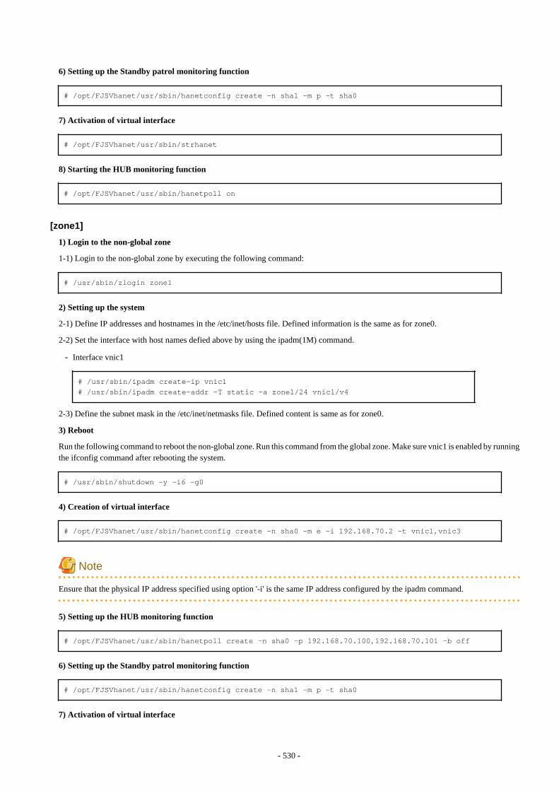
6) Setting up the Standby patrol monitoring function
# /opt/FJSVhanet/usr/sbin/hanetconfig create -n sha1 -m p -t sha0
7) Activation of virtual interface
# /opt/FJSVhanet/usr/sbin/strhanet
8) Starting the HUB monitoring function
# /opt/FJSVhanet/usr/sbin/hanetpoll on
[zone1]
1) Login to the non-global zone
1-1) Login to the non-global zone by executing the following command:
# /usr/sbin/zlogin zone1
2) Setting up the system
2-1) Define IP addresses and hostnames in the /etc/inet/hosts file. Defined information is the same as for zone0.
2-2) Set the interface with host names defied above by using the ipadm(1M) command.
- Interface vnic1
# /usr/sbin/ipadm create-ip vnic1# /usr/sbin/ipadm create-addr -T static -a zone1/24 vnic1/v4
2-3) Define the subnet mask in the /etc/inet/netmasks file. Defined content is same as for zone0.
3) Reboot
Run the following command to reboot the non-global zone. Run this command from the global zone. Make sure vnic1 is enabled by runningthe ifconfig command after rebooting the system.
# /usr/sbin/shutdown -y -i6 -g0
4) Creation of virtual interface
# /opt/FJSVhanet/usr/sbin/hanetconfig create -n sha0 -m e -i 192.168.70.2 -t vnic1,vnic3
Note
Ensure that the physical IP address specified using option '-i' is the same IP address configured by the ipadm command.
5) Setting up the HUB monitoring function
# /opt/FJSVhanet/usr/sbin/hanetpoll create -n sha0 -p 192.168.70.100,192.168.70.101 -b off
6) Setting up the Standby patrol monitoring function
# /opt/FJSVhanet/usr/sbin/hanetconfig create -n sha1 -m p -t sha0
7) Activation of virtual interface
- 530 -

# /opt/FJSVhanet/usr/sbin/strhanet
8) Starting the HUB monitoring function
# /opt/FJSVhanet/usr/sbin/hanetpoll on
- 531 -
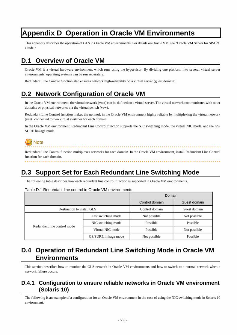
Appendix D Operation in Oracle VM EnvironmentsThis appendix describes the operation of GLS in Oracle VM environments. For details on Oracle VM, see "Oracle VM Server for SPARCGuide."
D.1 Overview of Oracle VMOracle VM is a virtual hardware environment which runs using the hypervisor. By dividing one platform into several virtual serverenvironments, operating systems can be run separately.
Redundant Line Control function also ensures network high-reliability on a virtual server (guest domain).
D.2 Network Configuration of Oracle VMIn the Oracle VM environment, the virtual network (vnet) can be defined on a virtual server. The virtual network communicates with otherdomains or physical networks via the virtual switch (vsw).
Redundant Line Control function makes the network in the Oracle VM environment highly reliable by multiplexing the virtual network(vnet) connected to two virtual switches for each domain.
In the Oracle VM environment, Redundant Line Control function supports the NIC switching mode, the virtual NIC mode, and the GS/SURE linkage mode.
Note
Redundant Line Control function multiplexes networks for each domain. In the Oracle VM environment, install Redundant Line Controlfunction for each domain.
D.3 Support Set for Each Redundant Line Switching ModeThe following table describes how each redundant line control function is supported in Oracle VM environments.
Table D.1 Redundant line control in Oracle VM environments
Domain
Control domain Guest domain
Destination to install GLS Control domain Guest domain
Redundant line control mode
Fast switching mode Not possible Not possible
NIC switching mode Possible Possible
Virtual NIC mode Possible Not possible
GS/SURE linkage mode Not possible Possible
D.4 Operation of Redundant Line Switching Mode in Oracle VMEnvironments
This section describes how to monitor the GLS network in Oracle VM environments and how to switch to a normal network when anetwork failure occurs.
D.4.1 Configuration to ensure reliable networks in Oracle VM environment(Solaris 10)
The following is an example of a configuration for an Oracle VM environment in the case of using the NIC switching mode in Solaris 10environment.
- 532 -
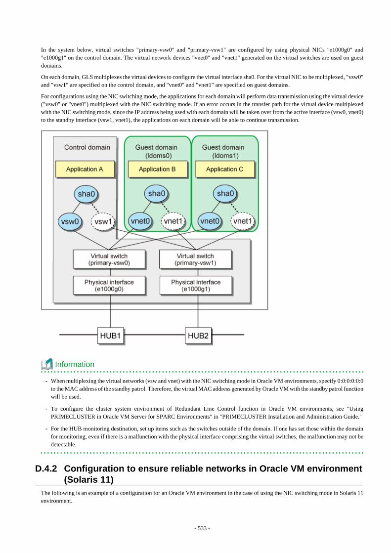
In the system below, virtual switches "primary-vsw0" and "primary-vsw1" are configured by using physical NICs "e1000g0" and"e1000g1" on the control domain. The virtual network devices "vnet0" and "vnet1" generated on the virtual switches are used on guestdomains.
On each domain, GLS multiplexes the virtual devices to configure the virtual interface sha0. For the virtual NIC to be multiplexed, "vsw0"and "vsw1" are specified on the control domain, and "vnet0" and "vnet1" are specified on guest domains.
For configurations using the NIC switching mode, the applications for each domain will perform data transmission using the virtual device("vsw0" or "vnet0") multiplexed with the NIC switching mode. If an error occurs in the transfer path for the virtual device multiplexedwith the NIC switching mode, since the IP address being used with each domain will be taken over from the active interface (vsw0, vnet0)to the standby interface (vsw1, vnet1), the applications on each domain will be able to continue transmission.
Information
- When multiplexing the virtual networks (vsw and vnet) with the NIC switching mode in Oracle VM environments, specify 0:0:0:0:0:0to the MAC address of the standby patrol. Therefore, the virtual MAC address generated by Oracle VM with the standby patrol functionwill be used.
- To configure the cluster system environment of Redundant Line Control function in Oracle VM environments, see "UsingPRIMECLUSTER in Oracle VM Server for SPARC Environments" in "PRIMECLUSTER Installation and Administration Guide."
- For the HUB monitoring destination, set up items such as the switches outside of the domain. If one has set those within the domainfor monitoring, even if there is a malfunction with the physical interface comprising the virtual switches, the malfunction may not bedetectable.
D.4.2 Configuration to ensure reliable networks in Oracle VM environment(Solaris 11)
The following is an example of a configuration for an Oracle VM environment in the case of using the NIC switching mode in Solaris 11environment.
- 533 -
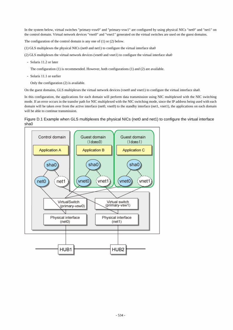
In the system below, virtual switches "primary-vsw0" and "primary-vsw1" are configured by using physical NICs "net0" and "net1" onthe control domain. Virtual network devices "vnet0" and "vnet1" generated on the virtual switches are used on the guest domains.
The configuration of the control domain is any one of (1) or (2) below.
(1) GLS multiplexes the physical NICs (net0 and net1) to configure the virtual interface sha0
(2) GLS multiplexes the virtual network devices (vnet0 and vnet1) to configure the virtual interface sha0
- Solaris 11.2 or later
The configuration (1) is recommended. However, both configurations (1) and (2) are available.
- Solaris 11.1 or earlier
Only the configuration (2) is available.
On the guest domains, GLS multiplexes the virtual network devices (vnet0 and vnet1) to configure the virtual interface sha0.
In this configuration, the applications for each domain will perform data transmission using NIC multiplexed with the NIC switchingmode. If an error occurs in the transfer path for NIC multiplexed with the NIC switching mode, since the IP address being used with eachdomain will be taken over from the active interface (net0, vnet0) to the standby interface (net1, vnet1), the applications on each domainwill be able to continue transmission.
Figure D.1 Example when GLS multiplexes the physical NICs (net0 and net1) to configure the virtual interfacesha0
- 534 -
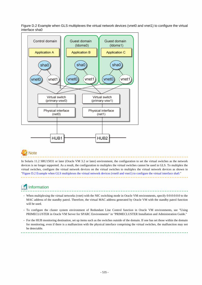
Figure D.2 Example when GLS multiplexes the virtual network devices (vnet0 and vnet1) to configure the virtualinterface sha0
Note
In Solaris 11.2 SRU15031 or later (Oracle VM 3.2 or later) environment, the configuration to set the virtual switches as the networkdevices is no longer supported. As a result, the configuration to multiplex the virtual switches cannot be used in GLS. To multiplex thevirtual switches, configure the virtual network devices on the virtual switches to multiplex the virtual network devices as shown in"Figure D.2 Example when GLS multiplexes the virtual network devices (vnet0 and vnet1) to configure the virtual interface sha0."
Information
- When multiplexing the virtual networks (vnet) with the NIC switching mode in Oracle VM environments, specify 0:0:0:0:0:0 to theMAC address of the standby patrol. Therefore, the virtual MAC address generated by Oracle VM with the standby patrol functionwill be used.
- To configure the cluster system environment of Redundant Line Control function in Oracle VM environments, see "UsingPRIMECLUSTER in Oracle VM Server for SPARC Environments" in "PRIMECLUSTER Installation and Administration Guide."
- For the HUB monitoring destination, set up items such as the switches outside of the domain. If one has set those within the domainfor monitoring, even if there is a malfunction with the physical interface comprising the virtual switches, the malfunction may notbe detectable.
- 535 -
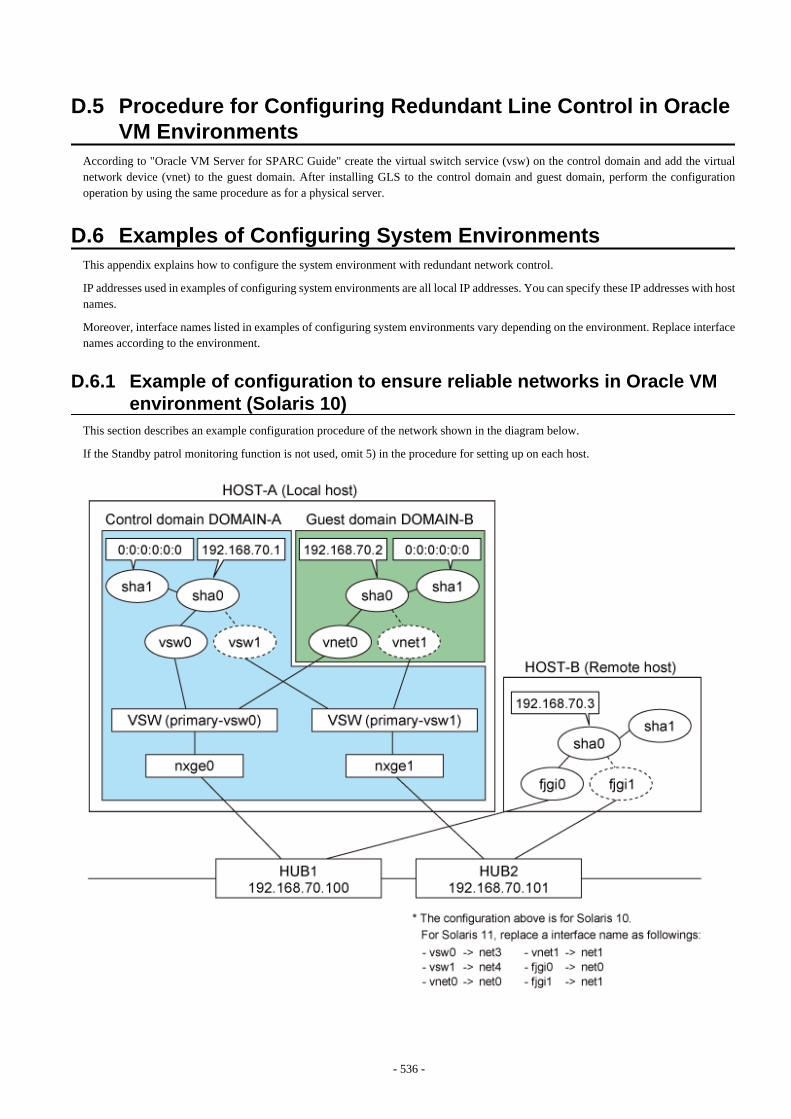
D.5 Procedure for Configuring Redundant Line Control in OracleVM Environments
According to "Oracle VM Server for SPARC Guide" create the virtual switch service (vsw) on the control domain and add the virtualnetwork device (vnet) to the guest domain. After installing GLS to the control domain and guest domain, perform the configurationoperation by using the same procedure as for a physical server.
D.6 Examples of Configuring System EnvironmentsThis appendix explains how to configure the system environment with redundant network control.
IP addresses used in examples of configuring system environments are all local IP addresses. You can specify these IP addresses with hostnames.
Moreover, interface names listed in examples of configuring system environments vary depending on the environment. Replace interfacenames according to the environment.
D.6.1 Example of configuration to ensure reliable networks in Oracle VMenvironment (Solaris 10)
This section describes an example configuration procedure of the network shown in the diagram below.
If the Standby patrol monitoring function is not used, omit 5) in the procedure for setting up on each host.
- 536 -
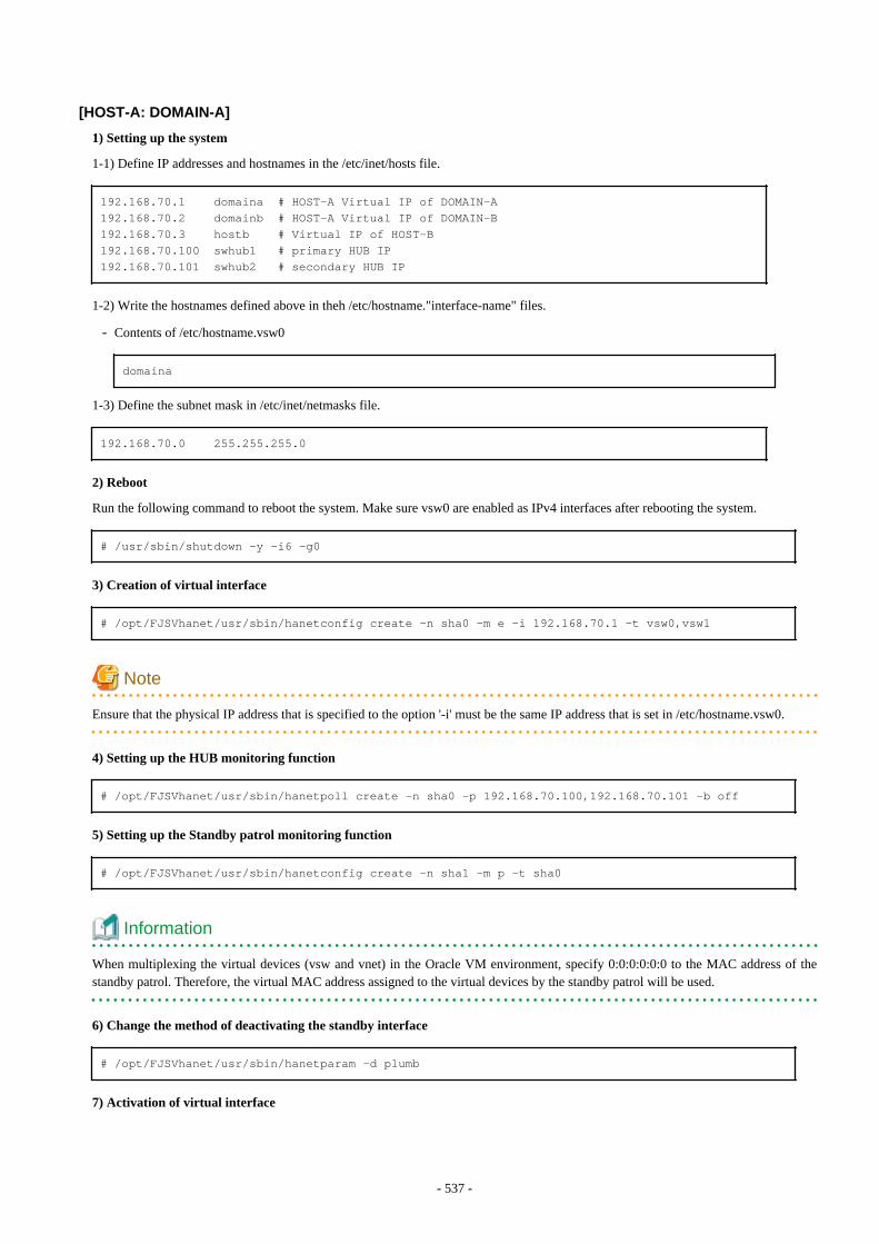
[HOST-A: DOMAIN-A]
1) Setting up the system
1-1) Define IP addresses and hostnames in the /etc/inet/hosts file.
192.168.70.1 domaina # HOST-A Virtual IP of DOMAIN-A192.168.70.2 domainb # HOST-A Virtual IP of DOMAIN-B192.168.70.3 hostb # Virtual IP of HOST-B 192.168.70.100 swhub1 # primary HUB IP192.168.70.101 swhub2 # secondary HUB IP
1-2) Write the hostnames defined above in theh /etc/hostname."interface-name" files.
- Contents of /etc/hostname.vsw0
domaina
1-3) Define the subnet mask in /etc/inet/netmasks file.
192.168.70.0 255.255.255.0
2) Reboot
Run the following command to reboot the system. Make sure vsw0 are enabled as IPv4 interfaces after rebooting the system.
# /usr/sbin/shutdown -y -i6 -g0
3) Creation of virtual interface
# /opt/FJSVhanet/usr/sbin/hanetconfig create -n sha0 -m e -i 192.168.70.1 -t vsw0,vsw1
Note
Ensure that the physical IP address that is specified to the option '-i' must be the same IP address that is set in /etc/hostname.vsw0.
4) Setting up the HUB monitoring function
# /opt/FJSVhanet/usr/sbin/hanetpoll create -n sha0 -p 192.168.70.100,192.168.70.101 -b off
5) Setting up the Standby patrol monitoring function
# /opt/FJSVhanet/usr/sbin/hanetconfig create -n sha1 -m p -t sha0
Information
When multiplexing the virtual devices (vsw and vnet) in the Oracle VM environment, specify 0:0:0:0:0:0 to the MAC address of thestandby patrol. Therefore, the virtual MAC address assigned to the virtual devices by the standby patrol will be used.
6) Change the method of deactivating the standby interface
# /opt/FJSVhanet/usr/sbin/hanetparam -d plumb
7) Activation of virtual interface
- 537 -
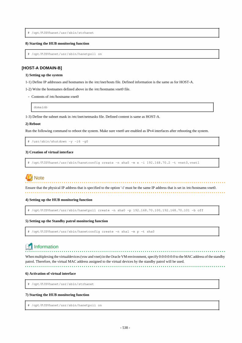
# /opt/FJSVhanet/usr/sbin/strhanet
8) Starting the HUB monitoring function
# /opt/FJSVhanet/usr/sbin/hanetpoll on
[HOST-A DOMAIN-B]
1) Setting up the system
1-1) Define IP addresses and hostnames in the /etc/inet/hosts file. Defined information is the same as for HOST-A.
1-2) Write the hostnames defined above in the /etc/hostname.vnet0 file.
- Contents of /etc/hostname.vnet0
domainb
1-3) Define the subnet mask in /etc/inet/netmasks file. Defined content is same as HOST-A.
2) Reboot
Run the following command to reboot the system. Make sure vnet0 are enabled as IPv4 interfaces after rebooting the system.
# /usr/sbin/shutdown -y -i6 -g0
3) Creation of virtual interface
# /opt/FJSVhanet/usr/sbin/hanetconfig create -n sha0 -m e -i 192.168.70.2 -t vnet0,vnet1
Note
Ensure that the physical IP address that is specified to the option '-i' must be the same IP address that is set in /etc/hostname.vnet0.
4) Setting up the HUB monitoring function
# /opt/FJSVhanet/usr/sbin/hanetpoll create -n sha0 -p 192.168.70.100,192.168.70.101 -b off
5) Setting up the Standby patrol monitoring function
# /opt/FJSVhanet/usr/sbin/hanetconfig create -n sha1 -m p -t sha0
Information
When multiplexing the virtualdevices (vsw and vnet) in the Oracle VM environment, specify 0:0:0:0:0:0 to the MAC address of the standbypatrol. Therefore, the virtual MAC address assigned to the virtual devices by the standby patrol will be used.
6) Activation of virtual interface
# /opt/FJSVhanet/usr/sbin/strhanet
7) Starting the HUB monitoring function
# /opt/FJSVhanet/usr/sbin/hanetpoll on
- 538 -

[HOST-B]
1) Setting up the system
1-1) Define IP addresses and hostnames in the /etc/inet/hosts file. Defined information is the same as for HOST-A DOMAIN-A.
1-2) Write the hostnames defined above in the /etc/hostname.fjgi0 file.
- Contents of /etc/hostname.fjgi0
hostb
1-3) Define the subnet mask in the /etc/inet/netmasks file. Defined content is same as HOST-A.
2) Reboot
Run the following command to reboot the system. Make sure fjgi0 are enabled as IPv4 interfaces after rebooting the system.
# /usr/sbin/shutdown -y -i6 -g0
3) Creation of virtual interface
# /opt/FJSVhanet/usr/sbin/hanetconfig create -n sha0 -m e -i 192.168.70.3 -t fjgi0,fjgi1
Note
Ensure that the physical IP address that is specified to the option '-e' must be the same IP address that is set in /etc/hostname.fjgi0.
4) Setting up the HUB monitoring function
# /opt/FJSVhanet/usr/sbin/hanetpoll create -n sha0 -p 192.168.70.100,192.168.70.101 -b off
5) Setting up the Standby patrol monitoring function
# /opt/FJSVhanet/usr/sbin/hanetconfig create -n sha1 -m p -t sha0
6) Activation of virtual interface
# /opt/FJSVhanet/usr/sbin/strhanet
7) Starting the HUB monitoring function
# /opt/FJSVhanet/usr/sbin/hanetpoll on
D.6.2 Example of configuration to ensure reliable networks in Oracle VMenvironment (Solaris 11)
This section describes an example configuration procedure of the network shown in the diagram below.
If the Standby patrol monitoring function is not used, omit 4) in the procedure for setting up on each host.
- 539 -

[HOST-A: DOMAIN-A]
1) Setting up the system
1-1) Define IP addresses and hostnames in the /etc/inet/hosts file.
192.168.70.1 domaina # HOST-A Virtual IP of DOMAIN-A192.168.70.2 domainb # HOST-A Virtual IP of DOMAIN-B192.168.70.3 hostb # Virtual IP of HOST-B 192.168.70.100 swhub1 # primary HUB IP192.168.70.101 swhub2 # secondary HUB IP
1-2) By using the ipadm(1M) command, configure the settings with the interface to be used and the host names defined in step 1-1).
- Interface to be used: net0
# /usr/sbin/ipadm create-ip net0# /usr/sbin/ipadm create-addr -T static -a domaina/24 net0/v4
- 1-3) Define the subnet mask in /etc/inet/netmasks file.
192.168.70.0 255.255.255.0
2) Creation of virtual interface
# /opt/FJSVhanet/usr/sbin/hanetconfig create -n sha0 -m e -i 192.168.70.1 -t net0,net1
- 540 -
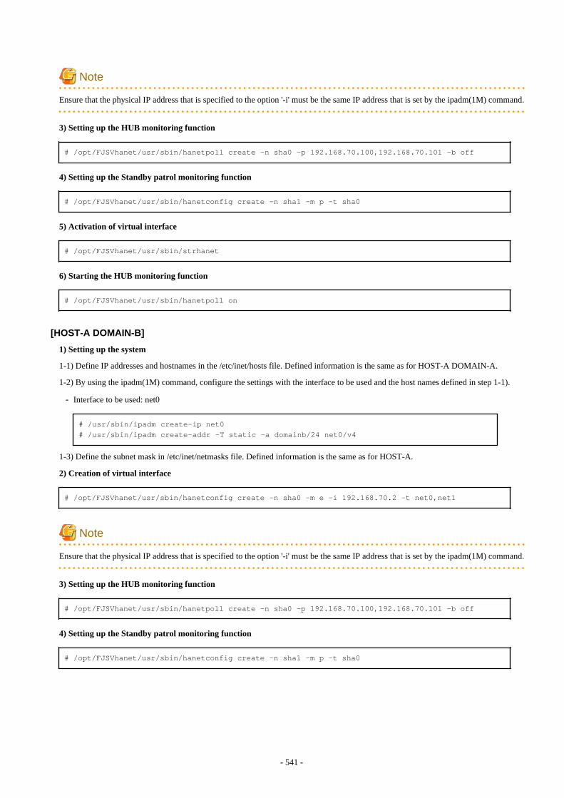
Note
Ensure that the physical IP address that is specified to the option '-i' must be the same IP address that is set by the ipadm(1M) command.
3) Setting up the HUB monitoring function
# /opt/FJSVhanet/usr/sbin/hanetpoll create -n sha0 -p 192.168.70.100,192.168.70.101 -b off
4) Setting up the Standby patrol monitoring function
# /opt/FJSVhanet/usr/sbin/hanetconfig create -n sha1 -m p -t sha0
5) Activation of virtual interface
# /opt/FJSVhanet/usr/sbin/strhanet
6) Starting the HUB monitoring function
# /opt/FJSVhanet/usr/sbin/hanetpoll on
[HOST-A DOMAIN-B]
1) Setting up the system
1-1) Define IP addresses and hostnames in the /etc/inet/hosts file. Defined information is the same as for HOST-A DOMAIN-A.
1-2) By using the ipadm(1M) command, configure the settings with the interface to be used and the host names defined in step 1-1).
- Interface to be used: net0
# /usr/sbin/ipadm create-ip net0# /usr/sbin/ipadm create-addr -T static -a domainb/24 net0/v4
1-3) Define the subnet mask in /etc/inet/netmasks file. Defined information is the same as for HOST-A.
2) Creation of virtual interface
# /opt/FJSVhanet/usr/sbin/hanetconfig create -n sha0 -m e -i 192.168.70.2 -t net0,net1
Note
Ensure that the physical IP address that is specified to the option '-i' must be the same IP address that is set by the ipadm(1M) command.
3) Setting up the HUB monitoring function
# /opt/FJSVhanet/usr/sbin/hanetpoll create -n sha0 -p 192.168.70.100,192.168.70.101 -b off
4) Setting up the Standby patrol monitoring function
# /opt/FJSVhanet/usr/sbin/hanetconfig create -n sha1 -m p -t sha0
- 541 -
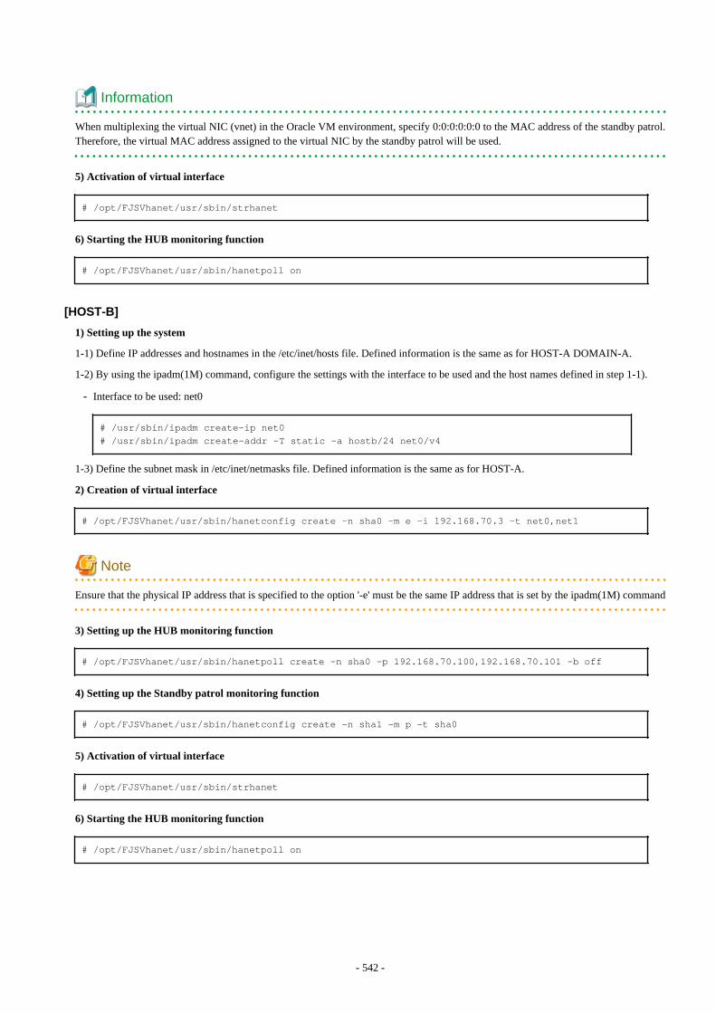
Information
When multiplexing the virtual NIC (vnet) in the Oracle VM environment, specify 0:0:0:0:0:0 to the MAC address of the standby patrol.Therefore, the virtual MAC address assigned to the virtual NIC by the standby patrol will be used.
5) Activation of virtual interface
# /opt/FJSVhanet/usr/sbin/strhanet
6) Starting the HUB monitoring function
# /opt/FJSVhanet/usr/sbin/hanetpoll on
[HOST-B]
1) Setting up the system
1-1) Define IP addresses and hostnames in the /etc/inet/hosts file. Defined information is the same as for HOST-A DOMAIN-A.
1-2) By using the ipadm(1M) command, configure the settings with the interface to be used and the host names defined in step 1-1).
- Interface to be used: net0
# /usr/sbin/ipadm create-ip net0# /usr/sbin/ipadm create-addr -T static -a hostb/24 net0/v4
1-3) Define the subnet mask in /etc/inet/netmasks file. Defined information is the same as for HOST-A.
2) Creation of virtual interface
# /opt/FJSVhanet/usr/sbin/hanetconfig create -n sha0 -m e -i 192.168.70.3 -t net0,net1
Note
Ensure that the physical IP address that is specified to the option '-e' must be the same IP address that is set by the ipadm(1M) command
3) Setting up the HUB monitoring function
# /opt/FJSVhanet/usr/sbin/hanetpoll create -n sha0 -p 192.168.70.100,192.168.70.101 -b off
4) Setting up the Standby patrol monitoring function
# /opt/FJSVhanet/usr/sbin/hanetconfig create -n sha1 -m p -t sha0
5) Activation of virtual interface
# /opt/FJSVhanet/usr/sbin/strhanet
6) Starting the HUB monitoring function
# /opt/FJSVhanet/usr/sbin/hanetpoll on
- 542 -
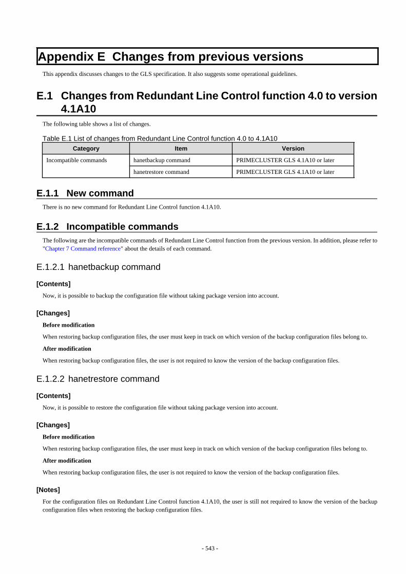
Appendix E Changes from previous versionsThis appendix discusses changes to the GLS specification. It also suggests some operational guidelines.
E.1 Changes from Redundant Line Control function 4.0 to version4.1A10
The following table shows a list of changes.
Table E.1 List of changes from Redundant Line Control function 4.0 to 4.1A10
Category Item Version
Incompatible commands hanetbackup command PRIMECLUSTER GLS 4.1A10 or later
hanetrestore command PRIMECLUSTER GLS 4.1A10 or later
E.1.1 New commandThere is no new command for Redundant Line Control function 4.1A10.
E.1.2 Incompatible commandsThe following are the incompatible commands of Redundant Line Control function from the previous version. In addition, please refer to"Chapter 7 Command reference" about the details of each command.
E.1.2.1 hanetbackup command
[Contents]
Now, it is possible to backup the configuration file without taking package version into account.
[Changes]
Before modification
When restoring backup configuration files, the user must keep in track on which version of the backup configuration files belong to.
After modification
When restoring backup configuration files, the user is not required to know the version of the backup configuration files.
E.1.2.2 hanetrestore command
[Contents]
Now, it is possible to restore the configuration file without taking package version into account.
[Changes]
Before modification
When restoring backup configuration files, the user must keep in track on which version of the backup configuration files belong to.
After modification
When restoring backup configuration files, the user is not required to know the version of the backup configuration files.
[Notes]
For the configuration files on Redundant Line Control function 4.1A10, the user is still not required to know the version of the backupconfiguration files when restoring the backup configuration files.
- 543 -
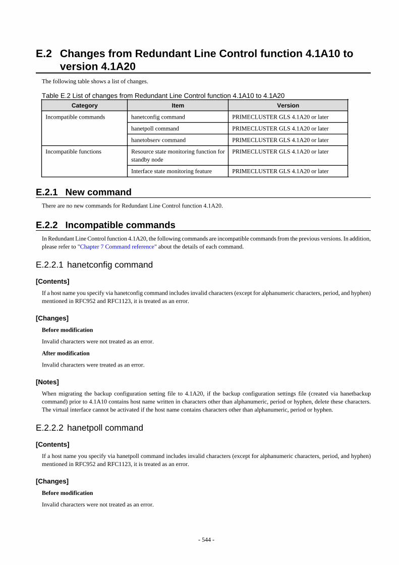
E.2 Changes from Redundant Line Control function 4.1A10 toversion 4.1A20
The following table shows a list of changes.
Table E.2 List of changes from Redundant Line Control function 4.1A10 to 4.1A20
Category Item Version
Incompatible commands hanetconfig command PRIMECLUSTER GLS 4.1A20 or later
hanetpoll command PRIMECLUSTER GLS 4.1A20 or later
hanetobserv command PRIMECLUSTER GLS 4.1A20 or later
Incompatible functions Resource state monitoring function forstandby node
PRIMECLUSTER GLS 4.1A20 or later
Interface state monitoring feature PRIMECLUSTER GLS 4.1A20 or later
E.2.1 New commandThere are no new commands for Redundant Line Control function 4.1A20.
E.2.2 Incompatible commandsIn Redundant Line Control function 4.1A20, the following commands are incompatible commands from the previous versions. In addition,please refer to "Chapter 7 Command reference" about the details of each command.
E.2.2.1 hanetconfig command
[Contents]
If a host name you specify via hanetconfig command includes invalid characters (except for alphanumeric characters, period, and hyphen)mentioned in RFC952 and RFC1123, it is treated as an error.
[Changes]
Before modification
Invalid characters were not treated as an error.
After modification
Invalid characters were treated as an error.
[Notes]
When migrating the backup configuration setting file to 4.1A20, if the backup configuration settings file (created via hanetbackupcommand) prior to 4.1A10 contains host name written in characters other than alphanumeric, period or hyphen, delete these characters.The virtual interface cannot be activated if the host name contains characters other than alphanumeric, period or hyphen.
E.2.2.2 hanetpoll command
[Contents]
If a host name you specify via hanetpoll command includes invalid characters (except for alphanumeric characters, period, and hyphen)mentioned in RFC952 and RFC1123, it is treated as an error.
[Changes]
Before modification
Invalid characters were not treated as an error.
- 544 -
After modification
Invalid characters were treated as an error.
[Notes]
When migrating the backup configuration setting file to 4.1A20, if the backup configuration settings file (created via hanetbackupcommand) prior to 4.1A10 contains host name written in characters other than alphanumeric, period or hyphen, delete these characters.The virtual interface cannot be activated if the host name contains characters other than alphanumeric, period or hyphen.
E.2.2.3 hanetobserv command
[Contents]
If a host name you specify via hanetobserv command includes invalid characters (except for alphanumeric characters, period, and hyphen)mentioned in RFC952 and RFC1123, it is treated as an error. For details on this issue, refer to "7.5 hanetobserv Command".
[Changes]
Before modification
Invalid characters were not treated as an error.
After modification
Invalid characters were treated as an error.
[Notes]
When migrating the backup configuration setting file to 4.1A20, if the backup configuration settings file (created via hanetbackupcommand) prior to 4.1A10 contains host name written in characters other than alphanumeric, period or hyphen, delete these characters.The virtual interface cannot be activated if the host name contains characters other than alphanumeric, period or hyphen.
E.2.3 Other incompatibles
E.2.3.1 Resource state monitoring function for standby node
[Contents]
When creating cluster application, it is possible to convert standby node of GLS resource into "Standby" state by setting a value of"StandbyTransition" attribute. If neglecting this configuration, it will not monitor the status of standby node of GLS resource. For reference,see "5.1.4 Monitoring resource status of standby node".
[Changes]
Before modification
GLS resource is set to "Offline" and it does not monitor the standby node of GLS resource state.
After modification
GLS resource is converted as "Standby" status and it monitors the standby node of GLS resource status.
[Notes]
- For GS/SURE linkage mode, the virtual interface on standby node side is inactive and its monitoring function stops. Therefore, itcannot monitor the GLS resource on the standby node. Unlike other modes, GS/SURE linkage mode does not require to specify"StandbyTransition" attribute because it does not run the resource monitoring.
- When attempting to restore the configuration file for 4.1A10 to the cluster system of version 4.1A20 or later using the backup functionof a cluster system, the value "StandbyTransistion" attribute will not be set as the default value. If this configuration is used withoutany modification, it does not monitor the GLS resource status in standby node. In such case, temporary stop the cluster applicationand use RMS Wizard to apply the "StandbyTransition" attribute in the configuration file.
- 545 -
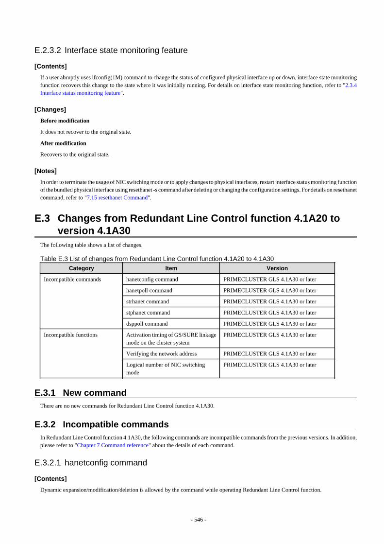
E.2.3.2 Interface state monitoring feature
[Contents]
If a user abruptly uses ifconfig(1M) command to change the status of configured physical interface up or down, interface state monitoringfunction recovers this change to the state where it was initially running. For details on interface state monitoring function, refer to "2.3.4Interface status monitoring feature".
[Changes]
Before modification
It does not recover to the original state.
After modification
Recovers to the original state.
[Notes]
In order to terminate the usage of NIC switching mode or to apply changes to physical interfaces, restart interface status monitoring functionof the bundled physical interface using resethanet -s command after deleting or changing the configuration settings. For details on resethanetcommand, refer to "7.15 resethanet Command".
E.3 Changes from Redundant Line Control function 4.1A20 toversion 4.1A30
The following table shows a list of changes.
Table E.3 List of changes from Redundant Line Control function 4.1A20 to 4.1A30
Category Item Version
Incompatible commands hanetconfig command PRIMECLUSTER GLS 4.1A30 or later
hanetpoll command PRIMECLUSTER GLS 4.1A30 or later
strhanet command PRIMECLUSTER GLS 4.1A30 or later
stphanet command PRIMECLUSTER GLS 4.1A30 or later
dsppoll command PRIMECLUSTER GLS 4.1A30 or later
Incompatible functions Activation timing of GS/SURE linkagemode on the cluster system
PRIMECLUSTER GLS 4.1A30 or later
Verifying the network address PRIMECLUSTER GLS 4.1A30 or later
Logical number of NIC switchingmode
PRIMECLUSTER GLS 4.1A30 or later
E.3.1 New commandThere are no new commands for Redundant Line Control function 4.1A30.
E.3.2 Incompatible commandsIn Redundant Line Control function 4.1A30, the following commands are incompatible commands from the previous versions. In addition,please refer to "Chapter 7 Command reference" about the details of each command.
E.3.2.1 hanetconfig command
[Contents]
Dynamic expansion/modification/deletion is allowed by the command while operating Redundant Line Control function.
- 546 -
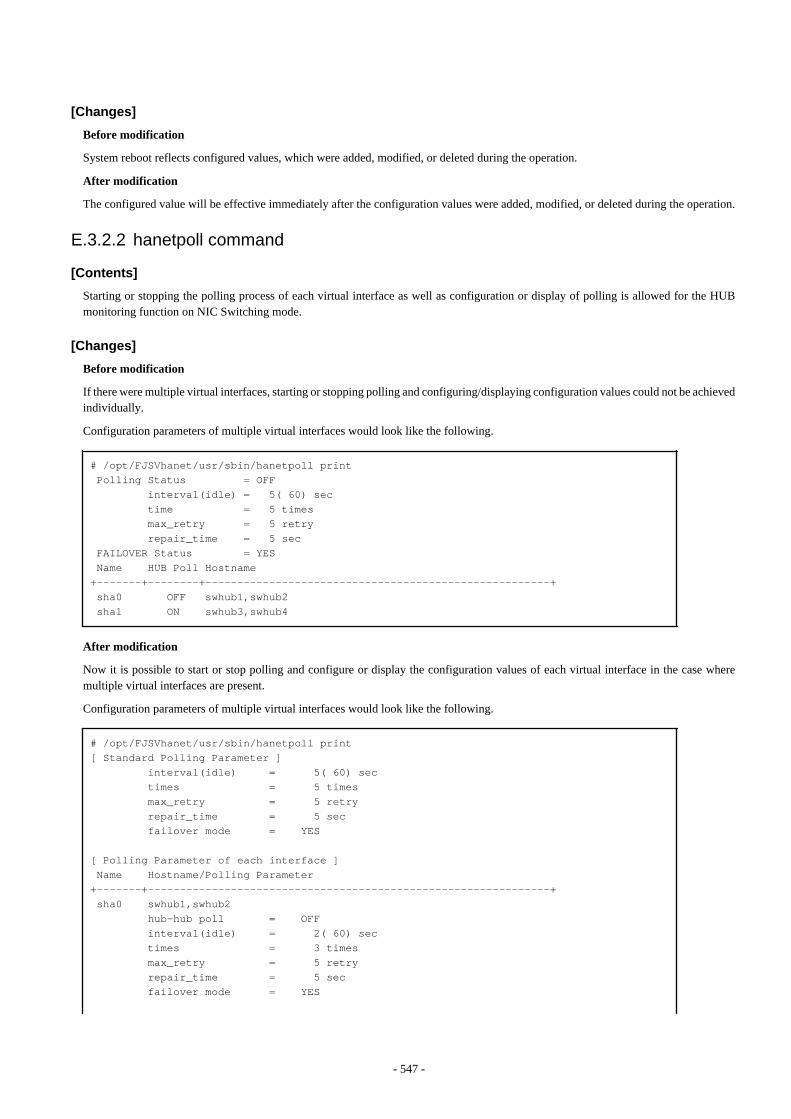
[Changes]
Before modification
System reboot reflects configured values, which were added, modified, or deleted during the operation.
After modification
The configured value will be effective immediately after the configuration values were added, modified, or deleted during the operation.
E.3.2.2 hanetpoll command
[Contents]
Starting or stopping the polling process of each virtual interface as well as configuration or display of polling is allowed for the HUBmonitoring function on NIC Switching mode.
[Changes]
Before modification
If there were multiple virtual interfaces, starting or stopping polling and configuring/displaying configuration values could not be achievedindividually.
Configuration parameters of multiple virtual interfaces would look like the following.
# /opt/FJSVhanet/usr/sbin/hanetpoll print Polling Status = OFF interval(idle) = 5( 60) sec time = 5 times max_retry = 5 retry repair_time = 5 sec FAILOVER Status = YES Name HUB Poll Hostname+-------+--------+------------------------------------------------------+ sha0 OFF swhub1,swhub2 sha1 ON swhub3,swhub4
After modification
Now it is possible to start or stop polling and configure or display the configuration values of each virtual interface in the case wheremultiple virtual interfaces are present.
Configuration parameters of multiple virtual interfaces would look like the following.
# /opt/FJSVhanet/usr/sbin/hanetpoll print[ Standard Polling Parameter ] interval(idle) = 5( 60) sec times = 5 times max_retry = 5 retry repair_time = 5 sec failover mode = YES
[ Polling Parameter of each interface ] Name Hostname/Polling Parameter+-------+---------------------------------------------------------------+ sha0 swhub1,swhub2 hub-hub poll = OFF interval(idle) = 2( 60) sec times = 3 times max_retry = 5 retry repair_time = 5 sec failover mode = YES
- 547 -
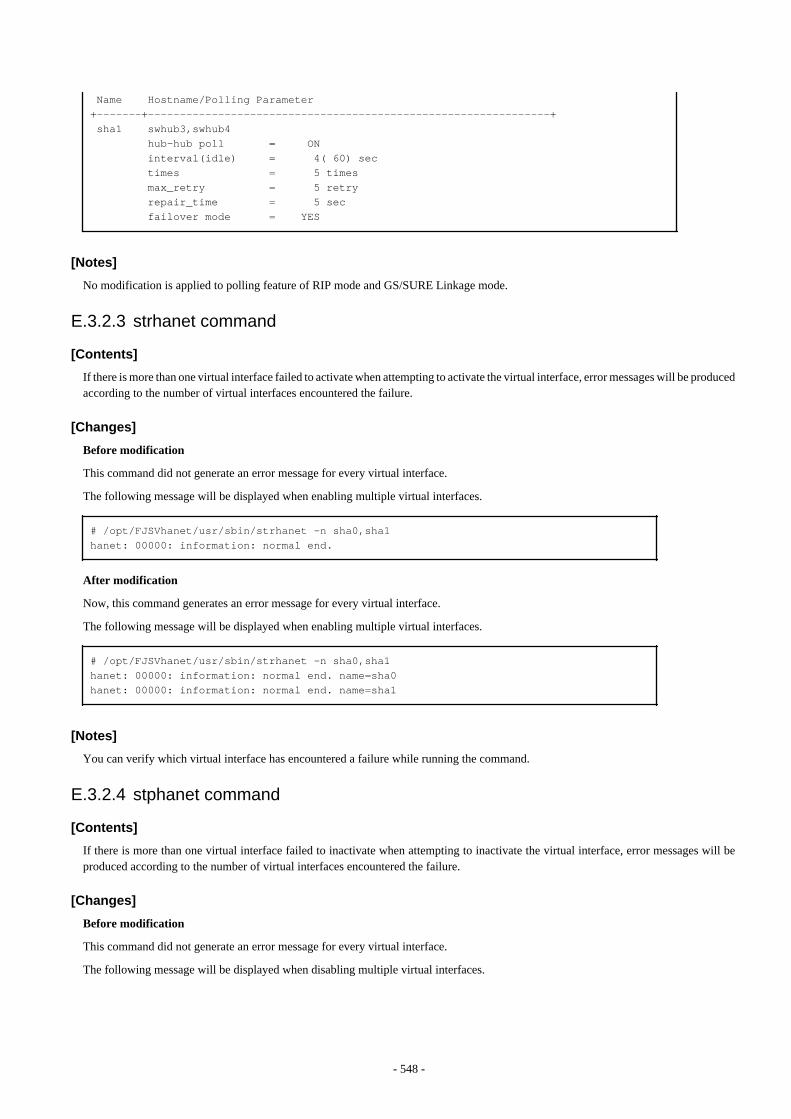
Name Hostname/Polling Parameter+-------+---------------------------------------------------------------+ sha1 swhub3,swhub4 hub-hub poll = ON interval(idle) = 4( 60) sec times = 5 times max_retry = 5 retry repair_time = 5 sec failover mode = YES
[Notes]
No modification is applied to polling feature of RIP mode and GS/SURE Linkage mode.
E.3.2.3 strhanet command
[Contents]
If there is more than one virtual interface failed to activate when attempting to activate the virtual interface, error messages will be producedaccording to the number of virtual interfaces encountered the failure.
[Changes]
Before modification
This command did not generate an error message for every virtual interface.
The following message will be displayed when enabling multiple virtual interfaces.
# /opt/FJSVhanet/usr/sbin/strhanet -n sha0,sha1hanet: 00000: information: normal end.
After modification
Now, this command generates an error message for every virtual interface.
The following message will be displayed when enabling multiple virtual interfaces.
# /opt/FJSVhanet/usr/sbin/strhanet -n sha0,sha1hanet: 00000: information: normal end. name=sha0hanet: 00000: information: normal end. name=sha1
[Notes]
You can verify which virtual interface has encountered a failure while running the command.
E.3.2.4 stphanet command
[Contents]
If there is more than one virtual interface failed to inactivate when attempting to inactivate the virtual interface, error messages will beproduced according to the number of virtual interfaces encountered the failure.
[Changes]
Before modification
This command did not generate an error message for every virtual interface.
The following message will be displayed when disabling multiple virtual interfaces.
- 548 -
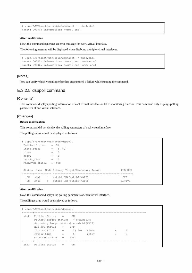
# /opt/FJSVhanet/usr/sbin/stphanet -n sha0,sha1hanet: 00000: information: normal end.
After modification
Now, this command generates an error message for every virtual interface.
The following message will be displayed when disabling multiple virtual interfaces.
# /opt/FJSVhanet/usr/sbin/stphanet -n sha0,sha1hanet: 00000: information: normal end. name=sha0hanet: 00000: information: normal end. name=sha1
[Notes]
You can verify which virtual interface has encountered a failure while running the command.
E.3.2.5 dsppoll command
[Contents]
This command displays polling information of each virtual interface on HUB monitoring function. This command only displays pollingparameters of one virtual interface.
[Changes]
Before modification
This command did not display the polling parameters of each virtual interface.
The polling status would be displayed as follows.
# /opt/FJSVhanet/usr/sbin/dsppoll Polling Status = ON inter(idle) = 5( 60) times = 5 retry = 5 repair_time = 5 FAILOVER Status = YES
Status Name Mode Primary Target/Secondary Target HUB-HUB+------+------+----+-------------------------------------------+-------+ ON sha0 d swhub1(ON)/swhub2(WAIT) OFF ON sha1 d swhub3(ON)/swhub4(WAIT) ACTIVE
After modification
Now, this command displays the polling parameters of each virtual interface.
The polling status would be displayed as follows.
# /opt/FJSVhanet/usr/sbin/dsppoll+------+-----------------------------------------------------------------------+ sha0 Polling Status = ON Primary Target(status) = swhub1(ON) Secondary Target(status) = swhub2(WAIT) HUB-HUB status = OFF interval(idle) = 2( 60) times = 3 repair_time = 5 retry = 5 FAILOVER Status = YES+------+-----------------------------------------------------------------------+ sha1 Polling Status = ON
- 549 -
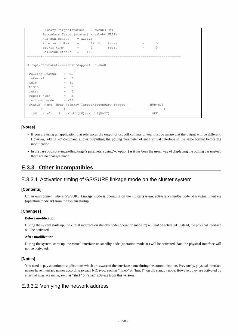
Primary Target(status) = swhub3(ON) Secondary Target(status) = swhub4(WAIT) HUB-HUB status = ACTIVE interval(idle) = 4( 60) times = 5 repair_time = 5 retry = 5 FAILOVER Status = YES+------+-----------------------------------------------------------------------+
# /opt/FJSVhanet/usr/sbin/dsppoll -n sha0
Polling Status = ON interval = 2 idle = 60 times = 3 retry = 5 repair_time = 5 failover mode = YES Status Name Mode Primary Target/Secondary Target HUB-HUB+------+------+----+-------------------------------------------+-------+ ON sha0 d swhub1(ON)/swhub2(WAIT) OFF
[Notes]
- If you are using an application that references the output of dsppoll command, you must be aware that the output will be different.However, adding '-n' command allows outputting the polling parameter of each virtual interface in the same format before themodification.
- In the case of displaying polling target's parameters using '-c' option (as it has been the usual way of displaying the polling parameter),there are no changes made.
E.3.3 Other incompatibles
E.3.3.1 Activation timing of GS/SURE linkage mode on the cluster system
[Contents]
On an environment where GS/SURE Linkage mode is operating on the cluster system, activate a standby node of a virtual interface(operation mode 'n') from the system startup.
[Changes]
Before modification
During the system starts up, the virtual interface on standby node (operation mode 'n') will not be activated. Instead, the physical interfacewill be activated.
After modification
During the system starts up, the virtual interface on standby node (operation mode 'n') will be activated. But, the physical interface willnot be activated.
[Notes]
You need to pay attention to applications which are aware of the interface name during the communication. Previously, physical interfacenames have interface names according to each NIC type, such as "hme0" or "hme1", on the standby node. However, they are activated bya virtual interface name, such as "sha1" or "sha2" activate from this version.
E.3.3.2 Verifying the network address
- 550 -
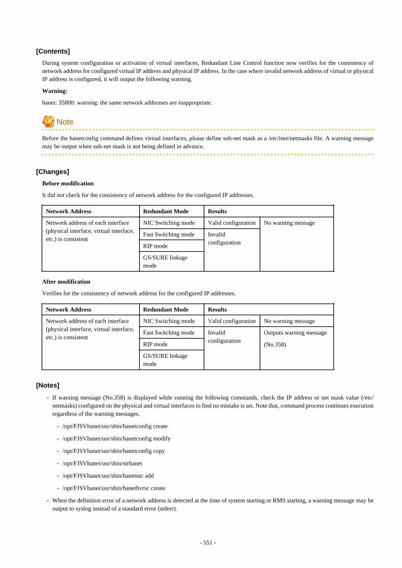
[Contents]
During system configuration or activation of virtual interfaces, Redundant Line Control function now verifies for the consistency ofnetwork address for configured virtual IP address and physical IP address. In the case where invalid network address of virtual or physicalIP address is configured, it will output the following warning.
Warning:
hanet: 35800: warning: the same network addresses are inappropriate.
Note
Before the hanetconfig command defines virtual interfaces, please define sub-net mask as a /etc/inet/netmasks file. A warning messagemay be output when sub-net mask is not being defined in advance.
[Changes]
Before modification
It did not check for the consistency of network address for the configured IP addresses.
Network Address Redundant Mode Results
Network address of each interface(physical interface, virtual interface,etc.) is consistent
NIC Switching mode Valid configuration No warning message
Fast Switching mode Invalidconfiguration
RIP mode
GS/SURE linkagemode
After modification
Verifies for the consistency of network address for the configured IP addresses.
Network Address Redundant Mode Results
Network address of each interface(physical interface, virtual interface,etc.) is consistent
NIC Switching mode Valid configuration No warning message
Fast Switching mode Invalidconfiguration
Outputs warning message
(No.358)RIP mode
GS/SURE linkagemode
[Notes]
- If warning message (No.358) is displayed while running the following commands, check the IP address or net mask value (/etc/netmasks) configured on the physical and virtual interfaces to find no mistake is set. Note that, command process continues executionregardless of the warning messages.
- /opt/FJSVhanet/usr/sbin/hanetconfig create
- /opt/FJSVhanet/usr/sbin/hanetconfig modify
- /opt/FJSVhanet/usr/sbin/hanetconfig copy
- /opt/FJSVhanet/usr/sbin/strhanet
- /opt/FJSVhanet/usr/sbin/hanetnic add
- /opt/FJSVhanet/usr/sbin/hanethvrsc create
- When the definition error of a network address is detected at the time of system starting or RMS starting, a warning message may beoutput to syslog instead of a standard error (stderr).
- 551 -
E.3.3.3 Logical number of NIC switching mode
[Contents]
In NIC switching mode (logical IP takeover), logical interfaces to which takeover IP addresses are added are changed.
[Changes]
Before modification
Logical interface names to which takeover IP addresses are added are assigned in the order of definition for virtual interfaces.
After modification
Logical interface names to which takeover IP addresses are added are automatically assigned in the order of activation by the operatingsystem.
E.4 Changes from Redundant Line Control function 4.1A30 toversion 4.1A40
The following table shows a list of changes.
Table E.4 List of changes from Redundant Line Control function 4.1A30 to 4.1A40
Category Item Version
Incompatiblecommand
None -
Incompatiblefunctions
Check for consistency between Solaris Zones andnetwork configuration
PRIMECLUSTER GLS 4.1A40 or later
Reserve takeover virtual interface for fastswitching mode
PRIMECLUSTER GLS 4.1A40 or later
E.4.1 New commandThere are no new commands for Redundant Line Control function 4.1A40.
E.4.2 Incompatible commandNo commands in the Redundant Line Control function 4.1A40 are incompatible from the previous versions.
E.4.3 Other incompatibles
E.4.3.1 Check for consistency between Solaris Zones and network configuration
[Contents]
If the Solaris Zone is already set on the system in fast switching or NIC switching mode, check consistency between the Solaris Zonesand network configuration.
If one of the following warning messages is output during environment settings, it is necessary to check the network configuration in theSolaris Zones.
Messages:
hanet: 36301: warning: IP address is already defined in zones. zone=<zone_name>hanet: 36401: warning: interface name is defined in zones. zone=<zone_name>hanet: 36501: warning: secondaryIF is specified in zones. zone=<zone_name>
- 552 -
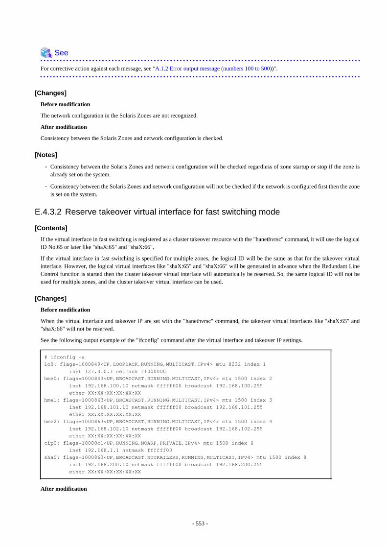
See
For corrective action against each message, see "A.1.2 Error output message (numbers 100 to 500))".
[Changes]
Before modification
The network configuration in the Solaris Zones are not recognized.
After modification
Consistency between the Solaris Zones and network configuration is checked.
[Notes]
- Consistency between the Solaris Zones and network configuration will be checked regardless of zone startup or stop if the zone isalready set on the system.
- Consistency between the Solaris Zones and network configuration will not be checked if the network is configured first then the zoneis set on the system.
E.4.3.2 Reserve takeover virtual interface for fast switching mode
[Contents]
If the virtual interface in fast switching is registered as a cluster takeover resource with the "hanethvrsc" command, it will use the logicalID No.65 or later like "shaX:65" and "shaX:66".
If the virtual interface in fast switching is specified for multiple zones, the logical ID will be the same as that for the takeover virtualinterface. However, the logical virtual interfaces like "shaX:65" and "shaX:66" will be generated in advance when the Redundant LineControl function is started then the cluster takeover virtual interface will automatically be reserved. So, the same logical ID will not beused for multiple zones, and the cluster takeover virtual interface can be used.
[Changes]
Before modification
When the virtual interface and takeover IP are set with the "hanethvrsc" command, the takeover virtual interfaces like "shaX:65" and"shaX:66" will not be reserved.
See the following output example of the "ifconfig" command after the virtual interface and takeover IP settings.
# ifconfig -alo0: flags=1000849<UP,LOOPBACK,RUNNING,MULTICAST,IPv4> mtu 8232 index 1 inet 127.0.0.1 netmask ff000000hme0: flags=1000843<UP,BROADCAST,RUNNING,MULTICAST,IPv4> mtu 1500 index 2 inet 192.168.100.10 netmask ffffff00 broadcast 192.168.100.255 ether XX:XX:XX:XX:XX:XXhme1: flags=1000863<UP,BROADCAST,RUNNING,MULTICAST,IPv4> mtu 1500 index 3 inet 192.168.101.10 netmask ffffff00 broadcast 192.168.101.255 ether XX:XX:XX:XX:XX:XXhme2: flags=1000863<UP,BROADCAST,RUNNING,MULTICAST,IPv4> mtu 1500 index 4 inet 192.168.102.10 netmask ffffff00 broadcast 192.168.102.255 ether XX:XX:XX:XX:XX:XXcip0: flags=10080c1<UP,RUNNING,NOARP,PRIVATE,IPv4> mtu 1500 index 6 inet 192.168.1.1 netmask ffffff00sha0: flags=1000863<UP,BROADCAST,NOTRAILERS,RUNNING,MULTICAST,IPv4> mtu 1500 index 8 inet 192.168.200.10 netmask ffffff00 broadcast 192.168.200.255 ether XX:XX:XX:XX:XX:XX
After modification
- 553 -
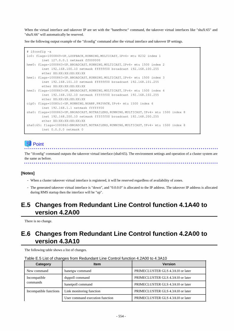
When the virtual interface and takeover IP are set with the "hanethvrsc" command, the takeover virtual interfaces like "shaX:65" and"shaX:66" will automatically be reserved.
See the following output example of the "ifconfig" command after the virtual interface and takeover IP settings.
# ifconfig -alo0: flags=1000849<UP,LOOPBACK,RUNNING,MULTICAST,IPv4> mtu 8232 index 1 inet 127.0.0.1 netmask ff000000hme0: flags=1000843<UP,BROADCAST,RUNNING,MULTICAST,IPv4> mtu 1500 index 2 inet 192.168.100.10 netmask ffffff00 broadcast 192.168.100.255 ether XX:XX:XX:XX:XX:XXhme1: flags=1000863<UP,BROADCAST,RUNNING,MULTICAST,IPv4> mtu 1500 index 3 inet 192.168.101.10 netmask ffffff00 broadcast 192.168.101.255 ether XX:XX:XX:XX:XX:XXhme2: flags=1000863<UP,BROADCAST,RUNNING,MULTICAST,IPv4> mtu 1500 index 4 inet 192.168.102.10 netmask ffffff00 broadcast 192.168.102.255 ether XX:XX:XX:XX:XX:XXcip0: flags=10080c1<UP,RUNNING,NOARP,PRIVATE,IPv4> mtu 1500 index 6 inet 192.168.1.1 netmask ffffff00sha0: flags=1000863<UP,BROADCAST,NOTRAILERS,RUNNING,MULTICAST,IPv4> mtu 1500 index 8 inet 192.168.200.10 netmask ffffff00 broadcast 192.168.200.255 ether XX:XX:XX:XX:XX:XXsha0:65: flags=1000862<BROADCAST,NOTRAILERS,RUNNING,MULTICAST,IPv4> mtu 1500 index 8 inet 0.0.0.0 netmask 0
Point
The "ifconfig" command outputs the takeover virtual interface (sha0:65). The environment settings and operation of a cluster system arethe same as before.
[Notes]
- When a cluster takeover virtual interface is registered, it will be reserved regardless of availability of zones.
- The generated takeover virtual interface is "down", and "0.0.0.0" is allocated to the IP address. The takeover IP address is allocatedduring RMS startup then the interface will be "up".
E.5 Changes from Redundant Line Control function 4.1A40 toversion 4.2A00
There is no change.
E.6 Changes from Redundant Line Control function 4.2A00 toversion 4.3A10
The following table shows a list of changes.
Table E.5 List of changes from Redundant Line Control function 4.2A00 to 4.3A10
Category Item Version
New command hanetgw command PRIMECLUSTER GLS 4.3A10 or later
Incompatiblecommands
dsppoll command PRIMECLUSTER GLS 4.3A10 or later
hanetpoll command PRIMECLUSTER GLS 4.3A10 or later
Incompatible functions Link monitoring function PRIMECLUSTER GLS 4.3A10 or later
User command execution function PRIMECLUSTER GLS 4.3A10 or later
- 554 -

Category Item Version
Virtual gateway PRIMECLUSTER GLS 4.3A10 or later
Standby patrol PRIMECLUSTER GLS 4.3A10 or later
RIP mode PRIMECLUSTER GLS 4.3A10 or later
Self-checking function PRIMECLUSTER GLS 4.3A10 or later
E.6.1 New command
E.6.1.1 hanetgw command
[Contents]
Commands to set, delete, and display virtual gateways required when using GS/SURE linkage mode are added. For details, see "7.16hanetgw Command".
[Changes]
Before modification
Commands to set, delete, and display virtual gateways required when using GS/SURE linkage mode were not provided.
After modification
Commands to set, delete, and display virtual gateways required when using GS/SURE linkage mode are added.
E.6.2 Incompatible commandsIn Redundant Line Control function 4.3A10, the following commands are incompatible commands from the previous versions.
In addition, please refer to "Chapter 7 Command reference" about the details of each command.
E.6.2.1 dsppoll command
[Contents]
For the monitoring information for each virtual interface, this changes the status displayed with "Polling Status."
[Changes]
Before modification
If there is even just one enabled HUB monitoring, the "Polling Status" will be displayed as ON.
If there is not even one enabled HUB monitoring, the "Polling Status" will be displayed as OFF.
After modification
If the HUB monitoring for the specified virtual interface is enabled, the "Polling Status" will be displayed as ON.
If the HUB monitoring for the specified virtual interface is disabled, the "Polling Status" will be displayed as OFF.
E.6.2.2 hanetpoll command
[Contents]
The condition for settings to be enabled is changed in the case that parameters of the HUB monitoring function are set to the specificvirtual interface by using the -n option of the hanetpoll on command.
[Changes]
Before modification
- 555 -
If parameters of the HUB monitoring function are changed after adding the definition of the virtual interface, the settings are enabled afterrestarting the Redundant Line Control function.
After modification
If parameters of the HUB monitoring function are changed after adding the definition of the virtual interface, the settings are enabledimmediately.
E.6.3 Other incompatibles
E.6.3.1 Link monitoring function
[Contents]
Enabling the link monitoring function in NIC switching mode allows NICs to be changed without waiting for a time out from the HUBmonitoring (HUB to HUB monitoring) when a NIC link is down.Moreover, to detect an error by the transfer path monitoring and switch NICs, check the link status of the target beforehand. If the targetis in the link down state and the state continues for 5 seconds or longer (when the standby patrol is set: 2.5 seconds or longer), restrictswitching NICs.This function is enabled by the -l option of the hanetpoll command.
[Changes]
Before modification
Even when the transmission route fails when a NIC link is down, the NIC is not changed until the failure is detected by the HUB monitoring(HUB to HUB monitoring).If an error is detected by the transfer path monitoring, switching is performed regardless of whether the link status of the target NIC.
After modification
When the transmission route fails when a NIC link is down, the NIC is changed without waiting for the failure detection by the HUBmonitoring (HUB to HUB monitoring).When an error is detected by the transfer path monitoring, restrict switching if the target NIC is in the link down state.
E.6.3.2 User command execution function (Setup file for NIC switching mode)
[Contents]
In NIC switching mode (Logical IP takeover), you can execute any command along with activation and inactivation of physical interfaces.
[Changes]
Before modification
In NIC switching mode (Logical IP takeover), scripts are not called on activation and inactivation of physical interfaces.
After modification
In NIC switching mode (Logical IP takeover), scripts are called on activation and inactivation of physical interfaces.
E.6.3.3 User command execution function (Setup file of the service for Redundant LineControl function)
[Contents]
The configuration file for Redundant Line Control function was added. For details see "3.6.10 Setting User command executionfunction."
[Changes]
Before modification
There is no corresponding script.
- 556 -
After modification
- /etc/opt/FJSVhanet/script/service.sh
You can start or restart an arbitrary service or application in conjunction with the transfer path monitoring service for Redundant LineControl function (svc:/network/fjsvhanet-poll) or the service for Redundant Line Control function (svc:/network/fjsvhanet).
- /etc/opt/FJSVhanet/script/monitor
You can start or restart an arbitrary service or application in conjunction with the self-checking function.
E.6.3.4 Virtual gateway
[Contents]
By setting a virtual gateway in GS/SURE linkage mode, applications for which local addresses cannot be fixed to virtual IP addressesbecome available.
[Changes]
Before modification
The requirement for user applications that can be operated in this mode is as follows:
- The virtual IP address of Redundant Line Control function is set so that it is fixed as a local IP address using the bind function orothers.
Thus, the Internet basic commands of Solaris such as ftp, telnet, and rlogin cannot be used in this mode.
After modification
The requirement for user applications that can be operated in this mode is as follows:
- Application using TCP/IP
E.6.3.5 Standby patrol
[Contents]
Specification of the MAC address which is used for the standby patrol can be omitted.
[Changes]
Before modification
You need to specify the MAC address when setting the standby patrol.
After modification
If you do not specify the MAC address when setting the standby patrol, the MAC address is automatically set.
E.6.3.6 RIP mode
[Contents]
RIP mode is removed.
[Changes]
Before modification
You can use RIP mode and Fast switching/RIP mode.
After modification
You cannot use RIP mode and Fast switching/RIP mode.
- 557 -
E.6.3.7 Self-checking function
[Contents]
This function periodically monitors the state of the control daemon and virtual driver by the self-checking function.
[Changes]
Before modification
The state of the control daemon and virtual driver are not monitored.
After modification
The state of the control daemon and virtual driver are monitored. If an error occurred in operation, the error can be notified to the user.Moreover, if the control daemon is stopped, it is automatically restarted.
E.6.3.8 Change of the error output message (205)
[Contents]
The error output message (205) is changed.
[Changes]
Before modification
20501: operation error: mode can't be changed for dual stack inteface.
After modification
20501: operation error: mode can't be changed for dual stack interface.
- 558 -
Appendix F Notice of supplemental informationThis appendix provides supplemental information regarding GLS.
F.1 Changing Methods of Activating and Inactivating InterfaceThis section describes how to activate or deactivate network interfaces controlled through redundant line control.
F.1.1 INTERSTAGE Traffic Director and Solaris ZonesIf you use "INTERSTAGE Traffic Director" or Solaris Zones for upper layers in NIC switching, it is necessary to change the method ofdeactivating standby physical interfaces by executing the following command:
# /opt/FJSVhanet/usr/sbin/hanetparam -d plumb
If you stop the "INTERSTAGE Traffic Director" or Solaris Zones, return the method of activating or deactivating the interfaces.
To return the method of deactivating the standby physical interfaces, execute the following command:
# /opt/FJSVhanet/usr/sbin/hanetparam -d unplumb
Note
The setting value is enabled when
- the system is rebooted,
- the virtual interfaces are deactivated or activated
- NIC is switched
Information
The changed value will be enabled in all the virtual interfaces in NIC switching.
F.2 TroubleshootingThe cause of the frequently occurred trouble when using a Redundant Line Control function and how to deal with it are explained in thissection.
F.2.1 Communication as expected cannot be performed (Common to IPv4and IPv6)
F.2.1.1 A default gateway is not set validPhenomenon:
A default gateway defined in /etc/defaultrouter at activation of a system is not valid.
Cause and how to deal with:
The setting of a default gateway defined in /etc/defaultrouter is set in /etc/rc2.d/S69inet at activation of a system. At this time, whenan interface of the same segment as that of the specified router, or when not activated, it is not possible to set a default gateway. In aRedundant Line Control function, a virtual interface is activated at activation of a userApplication in cluster operation. Therefore,occasionally not possible to set a default gateway.
- 559 -
Fast switching mode:
When using a virtual interface as a sending interface to a default gateway in cluster operation, change the timing to activate a virtualinterface by a hanetparam command.
NIC switching mode:
When using a physical IP address takeover function, and also when not activating an interface in a standby node, it is not possible touse a physical interface as a sending interface to a default gateway.
GS/SURE linkage mode:
It is not possible to use a virtual interface as a sending interface to a default gateway in cluster operation.
F.2.1.2 Fails to activate a system or an interface in the NIS environmentPhenomenon:
The following message is displayed and activation of a system or an interface hangs up.
ypbind[xxxx]: [ID xxxxxx daemon.error] NIS server not responding for domain "domain_name"; still trying
Cause and how to deal with:
When a system that a Redundant Line Control function works is set as an NIS client, occasionally not possible to connect NIS servertemporarily due to the process to deactivate an interface executed by a Redundant Line Control function. In such a case, if set a netmaskto an interface by an ifconfig command, occasionally the process to activate a system or an interface hangs up because an ifconfigcommand waits for the connection with NIS server to get a subnet mask.Be sure to set as follows when using a Redundant Line Control function in the NIS environment.
To specify "files" first in /etc/nsswitch.conf to refer "netmasks".
[Example of setting]
netmasks: files
or
netmasks: files [NOTFOUND=return] nis
As to accessing NIS server, design a network not to use an interface that is the target of control in a Redundant Line Control function(activation/deactivation) as possible.
F.2.1.3 Automatic address configuration lags behind for IPv6Phenomenon:
Automatic stateless address configuration for IPv6 may not operate instantly when activating IPv6. As a consequence, it takes time toadd site-local/global addresses.
Cause and how to deal with:
When activating an interface for IPv6, a link-local address is added to the physical interface to activate the physical interface. Toinstantly create site-local/global address by the automatic stateless address configuration, it transmits the "router solicitation message"to the adjacent router to request for router advertisement message from the router. However, once the interface activates, if spanningtree protocol (STP) is running on the HUB, it takes time to hold a communication. Thus it may fail to request router advertisementmessages. Because IPv6 router transmits the router advertisement message periodically and automatic stateless address automaticconfiguration runs after certain amount of time, it is possible to hold a communication of site-local/global addresses. Nevertheless, ifthe time interval parameter of transmitting the router advertisement message is set for a considerably long time, it may consume a longtime until the automatic stateless address configuration starts and to hold a communication. In such case, either establish a link foroperation NIC and standby NIC or modify the router setting so that a router transmits the router advertisement message within a fewerminutes interval.
- 560 -
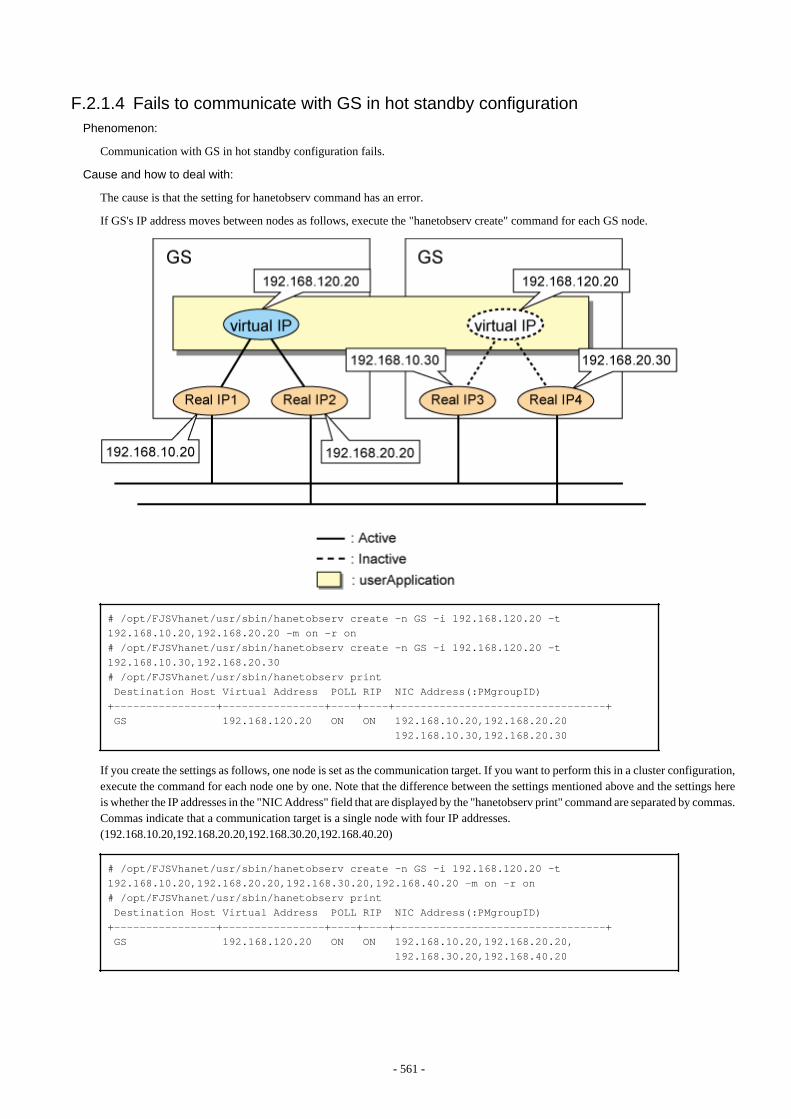
F.2.1.4 Fails to communicate with GS in hot standby configurationPhenomenon:
Communication with GS in hot standby configuration fails.
Cause and how to deal with:
The cause is that the setting for hanetobserv command has an error.
If GS's IP address moves between nodes as follows, execute the "hanetobserv create" command for each GS node.
# /opt/FJSVhanet/usr/sbin/hanetobserv create -n GS -i 192.168.120.20 -t 192.168.10.20,192.168.20.20 -m on -r on# /opt/FJSVhanet/usr/sbin/hanetobserv create -n GS -i 192.168.120.20 -t 192.168.10.30,192.168.20.30# /opt/FJSVhanet/usr/sbin/hanetobserv print Destination Host Virtual Address POLL RIP NIC Address(:PMgroupID)+----------------+----------------+----+----+---------------------------------+ GS 192.168.120.20 ON ON 192.168.10.20,192.168.20.20 192.168.10.30,192.168.20.30
If you create the settings as follows, one node is set as the communication target. If you want to perform this in a cluster configuration,execute the command for each node one by one. Note that the difference between the settings mentioned above and the settings hereis whether the IP addresses in the "NIC Address" field that are displayed by the "hanetobserv print" command are separated by commas.Commas indicate that a communication target is a single node with four IP addresses.(192.168.10.20,192.168.20.20,192.168.30.20,192.168.40.20)
# /opt/FJSVhanet/usr/sbin/hanetobserv create -n GS -i 192.168.120.20 -t 192.168.10.20,192.168.20.20,192.168.30.20,192.168.40.20 -m on -r on# /opt/FJSVhanet/usr/sbin/hanetobserv print Destination Host Virtual Address POLL RIP NIC Address(:PMgroupID)+----------------+----------------+----+----+---------------------------------+ GS 192.168.120.20 ON ON 192.168.10.20,192.168.20.20, 192.168.30.20,192.168.40.20
- 561 -
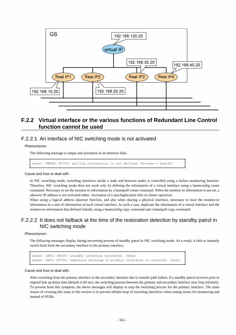
F.2.2 Virtual interface or the various functions of Redundant Line Controlfunction cannot be used
F.2.2.1 An interface of NIC switching mode is not activatedPhenomenon:
The following message is output and activation of an interface fails.
hanet: ERROR: 85700: polling information is not defined. Devname = sha0(0)
Cause and how to deal with:
In NIC switching mode, switching interfaces inside a node and between nodes is controlled using a failure monitoring function.Therefore, NIC switching mode does not work only by defining the information of a virtual interface using a hanetconfig createcommand. Necessary to set the monitor-to information by a hanetpoll create command. When the monitor-to information is not set, atakeover IP address is not activated either. Activation of a userApplication fails in cluster operation.When using a logical address takeover function, and also when sharing a physical interface, necessary to have the monitor-toinformation in a unit of information of each virtual interface. In such a case, duplicate the information of a virtual interface and themonitor-to information that defined initially using a hanetconfig copy command and a hanetpoll copy command.
F.2.2.2 It does not failback at the time of the restoration detection by standby patrol inNIC switching mode
Phenomenon:
The following messages display during recovering process of standby patrol in NIC switching mode. As a result, it fails to instantlyswitch back from the secondary interface to the primary interface.
hanet: INFO: 88500: standby interface recovered. (sha1)hanet: INFO: 89700: immediate exchange to primary interface is canceled. (sha1)
Cause and how to deal with:
After switching from the primary interface to the secondary interface due to transfer path failure, if a standby patrol recovers prior toelapsed link up delay time (default is 60 sec), the switching process between the primary and secondary interface may loop infinitely.To prevent from this symptom, the above messages will display to stop the switching process for the primary interface. The mainreason of covering this issue in this section is to prevent infinite loop of switching interfaces when setting routes for monitoring andinstead of HUBs.
- 562 -
F.2.2.3 Error detection message displays for standby patrol in NIC switching modePhenomenon:
The following message is output and activation of an interface fails.
hanet: WARNING: 87500: standby interface failed.
Cause and how to deal with:
On the network where VLAN switch exists on the transfer path monitored via standby patrol function, this error occurs if the followingtwo circumstances take place:
1) Connecting a redundant NIC to a port of disparate VLAN identifier.2) Connecting one of a redundant NIC or both redundant NICs to tagged member port of the switch.
The VLAN switch cannot communicate in between the ports where VLAN identifiers are disparate. Therefore, when connectingredundant NIC to disparate VLAN identifier, transmitting the monitoring frame fails between standby NIC and operation NIC,consequentially outputting 875 message. Additionally, even if VLAN identifiers are the same port and this port is set to tag member,and in the condition where the NIC does not support tagged VLAN (IEE802.1Q compliance), it still fails to retrieve tag frame fromthe switch. Once again, transmitting the monitoring frame fails outputting 875 message. To rectify this problem, double check theVLAN configuration of the switch and make sure VLAN identifier is identical on the port connecting redundant NIC. If the NIC youare using does not support tagged VLAN, set the port of the switch as non-tag member.
F.2.2.4 Command aborts and Redundant Line Control function startup failsSymptom
Executing hanetconfig create/delete command, hanetpoll create/delete command, dsphanet command, and dsppoll commands outputthe following error message and aborts. Also, the virtual interface fails to activate during the system startup."hanet: 56100: internal error: daemon process does not exist."
Cause and workaround
The problem is most likely occurred due to cut off of symbolic link that was linked to initialization script for Redundant Line Controlfunction. The user might have performed illegal operation to generate this issue. Therefore, the initialization script of Redundant LineControl function did not run during the system startup in which have caused activation failure of the virtual interface as well as startupfailure of GLS daemon (hanetcltd). In such a case, the command also aborts since the GLS daemon is not running. To resolve this issue, refer to the following recovery procedure to create the symbolic link under /etc/rc2.d and /etc/rc3.d that links tothe initialization script and reboot the system.
[Recovery Procedure]
# ln -s /etc/init.d/hanet /etc/rc2.d/S32hanet# ln -s /etc/init.d/hanet99 /etc/rc3.d/S99hanet
F.2.2.5 Solaris Zones cannot be startedSymptom
If the virtual interface in fast switching or physical interface in NIC switching is specified for the network setting, the following errormessage will be output and zone startup will fail:
# zoneadm -z zone0 bootcould not verify net address=192.168.80.10 physical=sha0: No such device or addresszoneadm: zone zone0 failed to verify
or
# zoneadm -z zone0 bootzoneadm: zone 'zone0': hme0:1: could not bring interface up: address in use by
- 563 -
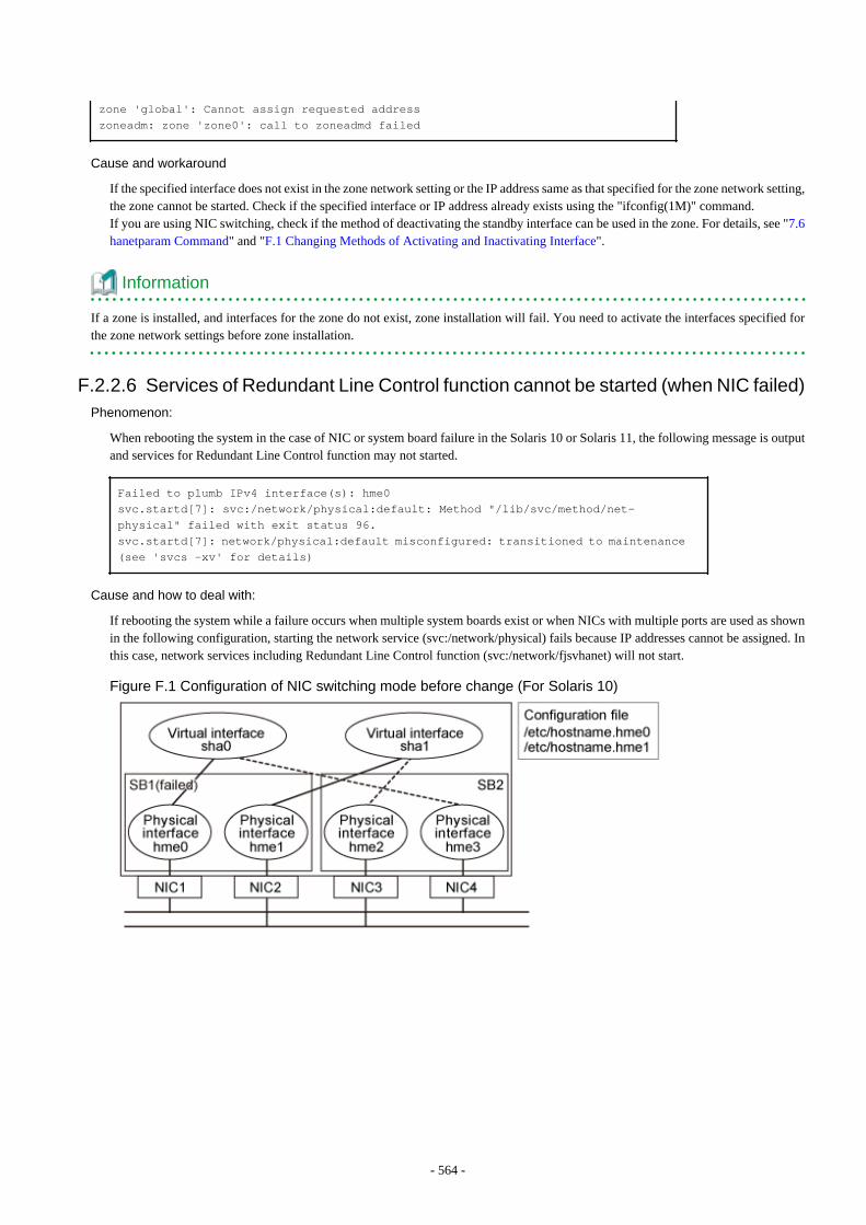
zone 'global': Cannot assign requested addresszoneadm: zone 'zone0': call to zoneadmd failed
Cause and workaround
If the specified interface does not exist in the zone network setting or the IP address same as that specified for the zone network setting,the zone cannot be started. Check if the specified interface or IP address already exists using the "ifconfig(1M)" command.If you are using NIC switching, check if the method of deactivating the standby interface can be used in the zone. For details, see "7.6hanetparam Command" and "F.1 Changing Methods of Activating and Inactivating Interface".
Information
If a zone is installed, and interfaces for the zone do not exist, zone installation will fail. You need to activate the interfaces specified forthe zone network settings before zone installation.
F.2.2.6 Services of Redundant Line Control function cannot be started (when NIC failed)Phenomenon:
When rebooting the system in the case of NIC or system board failure in the Solaris 10 or Solaris 11, the following message is outputand services for Redundant Line Control function may not started.
Failed to plumb IPv4 interface(s): hme0svc.startd[7]: svc:/network/physical:default: Method "/lib/svc/method/net-physical" failed with exit status 96.svc.startd[7]: network/physical:default misconfigured: transitioned to maintenance (see 'svcs -xv' for details)
Cause and how to deal with:
If rebooting the system while a failure occurs when multiple system boards exist or when NICs with multiple ports are used as shownin the following configuration, starting the network service (svc:/network/physical) fails because IP addresses cannot be assigned. Inthis case, network services including Redundant Line Control function (svc:/network/fjsvhanet) will not start.
Figure F.1 Configuration of NIC switching mode before change (For Solaris 10)
- 564 -
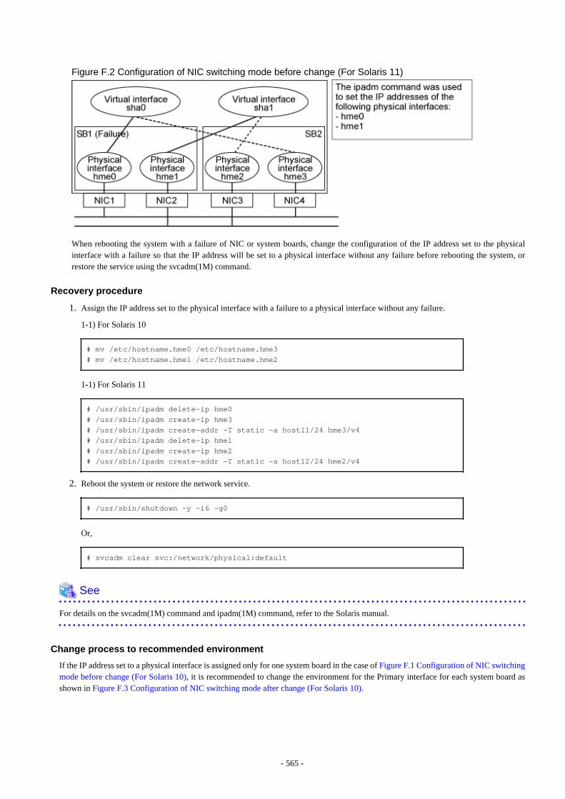
Figure F.2 Configuration of NIC switching mode before change (For Solaris 11)
When rebooting the system with a failure of NIC or system boards, change the configuration of the IP address set to the physicalinterface with a failure so that the IP address will be set to a physical interface without any failure before rebooting the system, orrestore the service using the svcadm(1M) command.
Recovery procedure
1. Assign the IP address set to the physical interface with a failure to a physical interface without any failure.
1-1) For Solaris 10
# mv /etc/hostname.hme0 /etc/hostname.hme3# mv /etc/hostname.hme1 /etc/hostname.hme2
1-1) For Solaris 11
# /usr/sbin/ipadm delete-ip hme0 # /usr/sbin/ipadm create-ip hme3 # /usr/sbin/ipadm create-addr -T static -a host11/24 hme3/v4 # /usr/sbin/ipadm delete-ip hme1 # /usr/sbin/ipadm create-ip hme2 # /usr/sbin/ipadm create-addr -T static -a host12/24 hme2/v4
2. Reboot the system or restore the network service.
# /usr/sbin/shutdown -y -i6 -g0
Or,
# svcadm clear svc:/network/physical:default
See
For details on the svcadm(1M) command and ipadm(1M) command, refer to the Solaris manual.
Change process to recommended environment
If the IP address set to a physical interface is assigned only for one system board in the case of Figure F.1 Configuration of NIC switchingmode before change (For Solaris 10), it is recommended to change the environment for the Primary interface for each system board asshown in Figure F.3 Configuration of NIC switching mode after change (For Solaris 10).
- 565 -
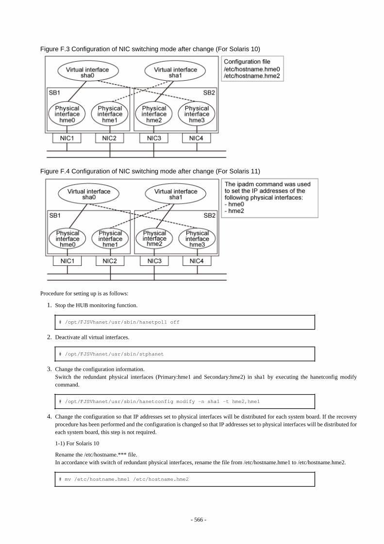
Figure F.3 Configuration of NIC switching mode after change (For Solaris 10)
Figure F.4 Configuration of NIC switching mode after change (For Solaris 11)
Procedure for setting up is as follows:
1. Stop the HUB monitoring function.
# /opt/FJSVhanet/usr/sbin/hanetpoll off
2. Deactivate all virtual interfaces.
# /opt/FJSVhanet/usr/sbin/stphanet
3. Change the configuration information.Switch the redundant physical interfaces (Primary:hme1 and Secondary:hme2) in sha1 by executing the hanetconfig modifycommand.
# /opt/FJSVhanet/usr/sbin/hanetconfig modify -n sha1 -t hme2,hme1
4. Change the configuration so that IP addresses set to physical interfaces will be distributed for each system board. If the recoveryprocedure has been performed and the configuration is changed so that IP addresses set to physical interfaces will be distributed foreach system board, this step is not required.
1-1) For Solaris 10
Rename the /etc/hostname.*** file.In accordance with switch of redundant physical interfaces, rename the file from /etc/hostname.hme1 to /etc/hostname.hme2.
# mv /etc/hostname.hme1 /etc/hostname.hme2
- 566 -
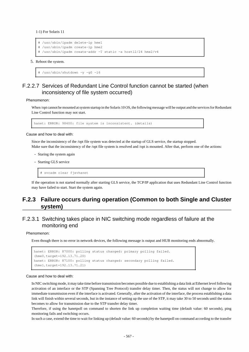
1-1) For Solaris 11
# /usr/sbin/ipadm delete-ip hme1# /usr/sbin/ipadm create-ip hme2# /usr/sbin/ipadm create-addr -T static -a host12/24 hme2/v4
5. Reboot the system.
# /usr/sbin/shutdown -y -g0 -i6
F.2.2.7 Services of Redundant Line Control function cannot be started (wheninconsistency of file system occurred)
Phenomenon:
When /opt cannot be mounted at system startup in the Solaris 10 OS, the following message will be output and the services for RedundantLine Control function may not start.
hanet: ERROR: 98400: file system is inconsistent. (details)
Cause and how to deal with:
Since the inconsistency of the /opt file system was detected at the startup of GLS service, the startup stopped.Make sure that the inconsistency of the /opt file system is resolved and /opt is mounted. After that, perform one of the actions:
- Staring the system again
- Starting GLS service
# svcadm clear fjsvhanet
If the operation is not started normally after starting GLS service, the TCP/IP application that uses Redundant Line Control functionmay have failed to start. Start the system again.
F.2.3 Failure occurs during operation (Common to both Single and Clustersystem)
F.2.3.1 Switching takes place in NIC switching mode regardless of failure at themonitoring end
Phenomenon:
Even though there is no error in network devices, the following message is output and HUB monitoring ends abnormally.
hanet: ERROR: 87000: polling status changed: primary polling failed. (hme0,target=192.13.71.20)hanet: ERROR: 87100: polling status changed: secondary polling failed. (hme1,target=192.13.71.21)
Cause and how to deal with:
In NIC switching mode, it may take time before transmission becomes possible due to establishing a data link at Ethernet level followingactivation of an interface or the STP (Spanning Tree Protocol) transfer delay timer. Then, the status will not change to allow forimmediate transmission even if the interface is activated. Generally, after the activation of the interface, the process establishing a datalink will finish within several seconds, but in the instance of setting up the use of the STP, it may take 30 to 50 seconds until the statusbecomes to allow for transmission due to the STP transfer delay timer.Therefore, if using the hanetpoll on command to shorten the link up completion waiting time (default value: 60 seconds), pingmonitoring fails and switching occurs.In such a case, extend the time to wait for linking up (default value: 60 seconds) by the hanetpoll on command according to the transfer
- 567 -
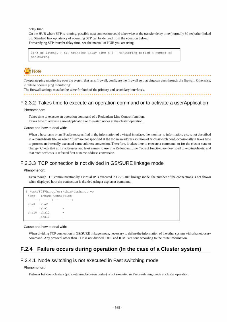
delay time.On the HUB where STP is running, possible next connection could take twice as the transfer delay time (normally 30 sec) after linkedup. Standard link up latency of operating STP can be derived from the equation below.For verifying STP transfer delay time, see the manual of HUB you are using.
link up latency > STP transfer delay time x 2 + monitoring period x number of monitoring
Note
To operate ping monitoring over the system that runs firewall, configure the firewall so that ping can pass through the firewall. Otherwise,it fails to operate ping monitoring.The firewall settings must be the same for both of the primary and secondary interfaces.
F.2.3.2 Takes time to execute an operation command or to activate a userApplicationPhenomenon:
Takes time to execute an operation command of a Redundant Line Control function.Takes time to activate a userApplication or to switch nodes at the cluster operation.
Cause and how to deal with:
When a host name or an IP address specified in the information of a virtual interface, the monitor-to information, etc. is not describedin /etc/inet/hosts file, or when "files" are not specified at the top in an address solution of /etc/nsswitch.conf, occasionally it takes timeto process an internally executed name-address conversion. Therefore, it takes time to execute a command, or for the cluster state tochange. Check that all IP addresses and host names to use in a Redundant Line Control function are described in /etc/inet/hosts, andthat /etc/inet/hosts is referred first at name-address conversion.
F.2.3.3 TCP connection is not divided in GS/SURE linkage modePhenomenon:
Even though TCP communication by a virtual IP is executed in GS/SURE linkage mode, the number of the connections is not shownwhen displayed how the connection is divided using a dsphanet command.
# /opt/FJSVhanet/usr/sbin/dsphanet -c Name IFname Connection+------+------+----------+ sha0 sha2 - sha1 - sha10 sha12 - sha11 -
Cause and how to deal with:
When dividing TCP connection in GS/SURE linkage mode, necessary to define the information of the other system with a hanetobservcommand. Any protocol other than TCP is not divided. UDP and ICMP are sent according to the route information.
F.2.4 Failure occurs during operation (In the case of a Cluster system)
F.2.4.1 Node switching is not executed in Fast switching modePhenomenon:
Failover between clusters (job switching between nodes) is not executed in Fast switching mode at cluster operation.
- 568 -
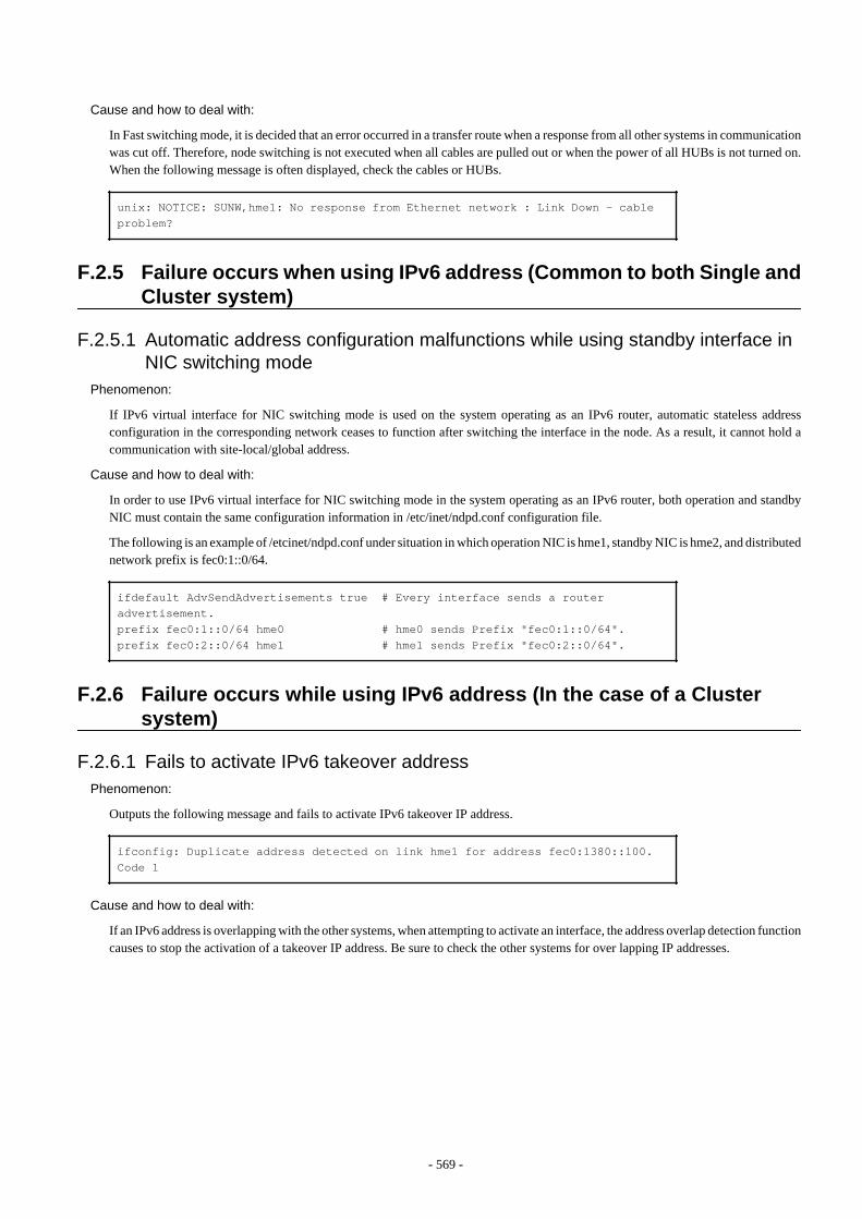
Cause and how to deal with:
In Fast switching mode, it is decided that an error occurred in a transfer route when a response from all other systems in communicationwas cut off. Therefore, node switching is not executed when all cables are pulled out or when the power of all HUBs is not turned on.When the following message is often displayed, check the cables or HUBs.
unix: NOTICE: SUNW,hme1: No response from Ethernet network : Link Down - cable problem?
F.2.5 Failure occurs when using IPv6 address (Common to both Single andCluster system)
F.2.5.1 Automatic address configuration malfunctions while using standby interface inNIC switching mode
Phenomenon:
If IPv6 virtual interface for NIC switching mode is used on the system operating as an IPv6 router, automatic stateless addressconfiguration in the corresponding network ceases to function after switching the interface in the node. As a result, it cannot hold acommunication with site-local/global address.
Cause and how to deal with:
In order to use IPv6 virtual interface for NIC switching mode in the system operating as an IPv6 router, both operation and standbyNIC must contain the same configuration information in /etc/inet/ndpd.conf configuration file.
The following is an example of /etcinet/ndpd.conf under situation in which operation NIC is hme1, standby NIC is hme2, and distributednetwork prefix is fec0:1::0/64.
ifdefault AdvSendAdvertisements true # Every interface sends a router advertisement.prefix fec0:1::0/64 hme0 # hme0 sends Prefix "fec0:1::0/64".prefix fec0:2::0/64 hme1 # hme1 sends Prefix "fec0:2::0/64".
F.2.6 Failure occurs while using IPv6 address (In the case of a Clustersystem)
F.2.6.1 Fails to activate IPv6 takeover addressPhenomenon:
Outputs the following message and fails to activate IPv6 takeover IP address.
ifconfig: Duplicate address detected on link hme1 for address fec0:1380::100. Code 1
Cause and how to deal with:
If an IPv6 address is overlapping with the other systems, when attempting to activate an interface, the address overlap detection functioncauses to stop the activation of a takeover IP address. Be sure to check the other systems for over lapping IP addresses.
- 569 -
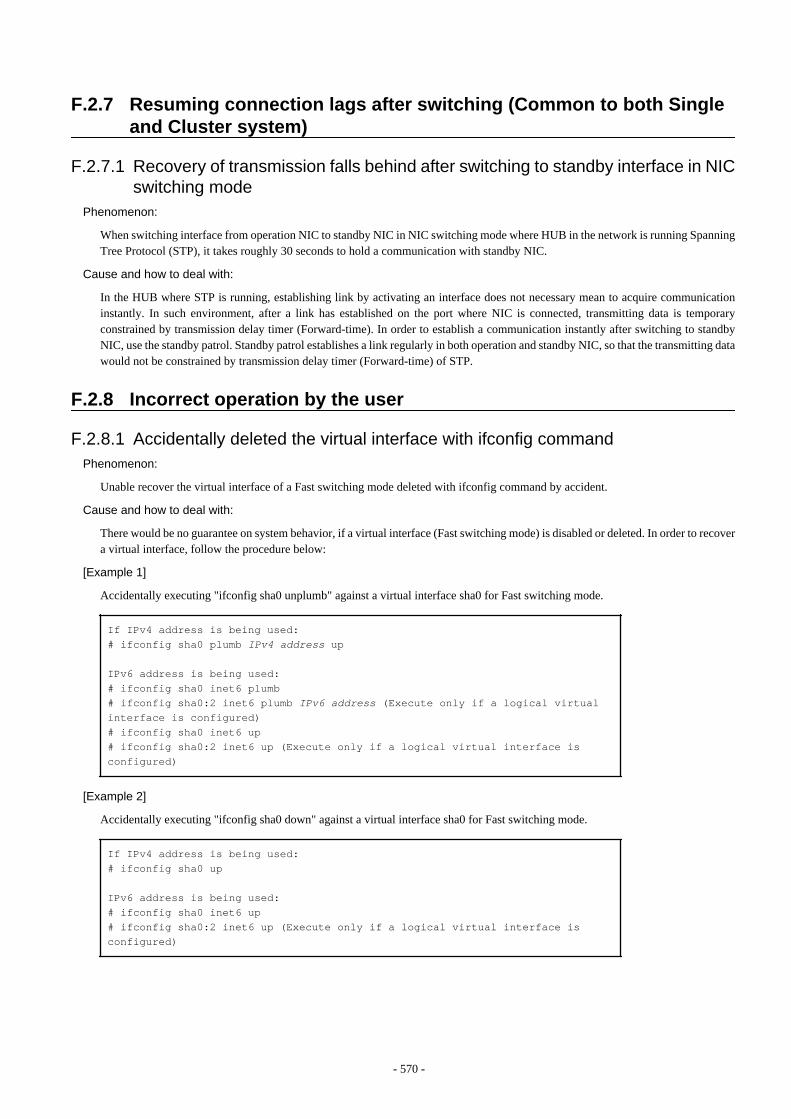
F.2.7 Resuming connection lags after switching (Common to both Singleand Cluster system)
F.2.7.1 Recovery of transmission falls behind after switching to standby interface in NICswitching mode
Phenomenon:
When switching interface from operation NIC to standby NIC in NIC switching mode where HUB in the network is running SpanningTree Protocol (STP), it takes roughly 30 seconds to hold a communication with standby NIC.
Cause and how to deal with:
In the HUB where STP is running, establishing link by activating an interface does not necessary mean to acquire communicationinstantly. In such environment, after a link has established on the port where NIC is connected, transmitting data is temporaryconstrained by transmission delay timer (Forward-time). In order to establish a communication instantly after switching to standbyNIC, use the standby patrol. Standby patrol establishes a link regularly in both operation and standby NIC, so that the transmitting datawould not be constrained by transmission delay timer (Forward-time) of STP.
F.2.8 Incorrect operation by the user
F.2.8.1 Accidentally deleted the virtual interface with ifconfig commandPhenomenon:
Unable recover the virtual interface of a Fast switching mode deleted with ifconfig command by accident.
Cause and how to deal with:
There would be no guarantee on system behavior, if a virtual interface (Fast switching mode) is disabled or deleted. In order to recovera virtual interface, follow the procedure below:
[Example 1]
Accidentally executing "ifconfig sha0 unplumb" against a virtual interface sha0 for Fast switching mode.
If IPv4 address is being used:# ifconfig sha0 plumb IPv4 address up
IPv6 address is being used:# ifconfig sha0 inet6 plumb# ifconfig sha0:2 inet6 plumb IPv6 address (Execute only if a logical virtual interface is configured)# ifconfig sha0 inet6 up# ifconfig sha0:2 inet6 up (Execute only if a logical virtual interface is configured)
[Example 2]
Accidentally executing "ifconfig sha0 down" against a virtual interface sha0 for Fast switching mode.
If IPv4 address is being used:# ifconfig sha0 up
IPv6 address is being used:# ifconfig sha0 inet6 up# ifconfig sha0:2 inet6 up (Execute only if a logical virtual interface is configured)
- 570 -
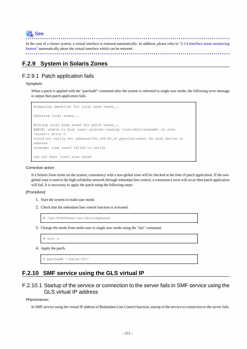
See
In the case of a cluster system, a virtual interface is restored automatically. In addition, please refer to "2.3.4 Interface status monitoringfeature" automatically about the virtual interface which can be restored.
F.2.9 System in Solaris Zones
F.2.9.1 Patch application failsSymptom:
When a patch is applied with the "patchadd" command after the system is rebooted in single user mode, the following error messageis output then patch application fails.
Preparing checklist for local zone check...
Checking local zones...
Booting local zone zone0 for patch check...ERROR: unable to boot zone: problem running </usr/sbin/zoneadm> on zone <zone0>: Error 0could not verify net address=192.168.80.10 physical=sha0: No such device or addresszoneadm: zone zone0 failed to verify
Can not boot local zone zone0
Corrective action:
If a Solaris Zone exists on the system, consistency with a non-global zone will be checked at the time of patch application. If the non-global zone is used in the high-reliability network through redundant line control, a consistency error will occur then patch applicationwill fail. It is necessary to apply the patch using the following steps:
[Procedure]
1. Start the system in multi-user mode.
2. Check that the redundant line control function is activated.
# /opt/FJSVhanet/usr/sbin/dsphanet
3. Change the mode from multi-user to single user mode using the "init" command.
# init s
4. Apply the patch.
# patchadd "<Patch-ID>"
F.2.10 SMF service using the GLS virtual IP
F.2.10.1 Startup of the service or connection to the server fails in SMF service using theGLS virtual IP address
Phenomenon:
In SMF service using the virtual IP address of Redundant Line Control function, startup of the service or connection to the server fails.
- 571 -

Cause and how to deal with:
The cause is that SMF service (routing or name service) requiring the virtual IP address is started up without waiting the service forRedundant Line Control function, which activates the virtual IP address.If the service uses the virtual IP address, set as the service starts up after the virtual IP address is activated.For details, see "3.6.10.3 Settings of the service for Redundant Line Control function".
- 572 -
Glossary Active interface
An interface currently used for communication.
[Related article] Standby interface
Automatic fail-back function
A function to automatically fail back without any operator when the failed LAN recovered. See a standby patrol function (automaticfail-back if a failure occurs) or a standby patrol function (immediate automatic fail-back) for the detail.
Cluster failover function (failover function)
A function to fail over between clusters if all physical interfaces bundled by a virtual interface caused an error or if an active nodepanicked or hung when operating clusters.
DR
Dynamic Reconfiguration
Dynamic switching function
A function to switch to a standby interface while an active interface is active.
ESF
Enhanced Support Facility
Fast switching mode
Fast switching mode keeps the communication alive during transfer route failure and increases the total throughput by multiplexingtransfer routes between servers on the same network.
Global zone
A global zone is the global view of the Solaris operating environment. There is always one global zone per Solaris instance. Eachsoftware partition that is created within the Solaris instance can be managed and controlled in the global zone.
[Related article] Solaris Zones, Non-global zone (Zone)
GLS
Stands for Global Link Services.
GS/SURE linkage mode
GS/SURE linkage mode multiplexes transfer routes between global server/SURE SYSTEM and ExINCA lies on the same network.This mode provides functionality of transfer route failover during transfer route failure in which implements high availability.
HUB monitoring function
A function to monitor from an active interface to a HUB connected to an active interface. It switches to a standby interface if detectedan error.
[Related article] Inter-HUB monitoring function, Line monitoring
HUB-to-HUB monitoring function
A function to monitor an error in the connection between the HUBs (cascade connection). The monitoring range is from an activeinterface to a HUB connected to an active interface, and to the one connected to a standby interface. This function includes themonitoring range of a HUB monitoring function. However, it does not monitor a standby interface.
[Related article] HUB monitoring function
- 573 -
LAN
Local area network
LAN card
The same meaning as that of NIC.
Line monitoring
The same meaning as that of HUB monitoring function.
[Related article] Inter-HUB monitoring function
Logical interface
A logical interface created in a different name to the same one physical interface. For instance, a logical interface to a physical interfaceeth0 is eth0:X (X is 0, 1, 2...)
[Related article] Logical IP address
Logical IP address (logical IP)
An IP address assigned to a logical interface.
[Related article] Logical interface
Logical IP address takeover function
A function to take over a logical IP address from cluster to cluster. It is possible to take over a logical IP address if switching from anactive node to a standby node occurred between clusters. A physical IP address is not taken over in this case.
Logical virtual interface
Logical virtual interface is a logical interface created as distinguished name for a virtual interface. For example, a logical virtualinterface for the virtual interface sha0 is represented as sha0:X (X refers to 2,3..64).
Note that if X becomes larger than 65, they are then used as a takeover virtual interface on a cluster environment.
Monitoring frame
A Monitoring frame is an unique frame GLS handles to monitor the transfer paths. Fast switching mode uses this feature to monitorassociate host. For NIC switching mode, it uses this feature as standby patrol function to monitor standby interfaces.
[Related article] Standby patrol function, HUB monitoring function, Inter-HUB monitoring function
NIC
Stands for Network Interface Card. Also called a LAN card.
NIC sharing function
A function to create more than one piece of configuration information by sharing the NIC if the adding physical IP address is the samein all NICs and configuration information. Use this function to assign more than one IP to a pair of the redundant NICs. Use this toexecute cluster mutual standby operation as well.
NIC switching mode
A mode to realize high reliability by exclusively using a redundant NIC and switching when an error occurred. It is necessary to connecta redundant NIC in the same network in this mode.
Non-global zone (Zone)
Each non-global zone has a security boundary around it. The security boundary is maintained by allowing zones to only communicatebetween themselves using networking APIs.
[Related article] Solaris Zones, Global zone
- 574 -
PHP
PCI Hot Plug
Physical interface
An interface created for the NIC equipped with in a system.
[Related article] Physical interface
Physical IP address (physical IP)
An IP address assigned to a physical interface.
[Related article] Physical interface
Physical IP address takeover function
Physical IP address takeover function is a function that takes over physical IP addresses between redundant NICs. On a cluster operation,it consists with two separate functions, they are Physical IP address takeover function I and IP address takeover function II.
Physical IP address takeover function I
This function takes over physical IP addresses between a cluster environment. Apply hanetconfig command with -e option beforecreating a virtual interface. It could takeover the physical IP address when switching occurs from operation node and standby node oncluster environment. Moreover, it activates physical interface on standby node of the cluster.
Physical IP address takeover function II
This function takes over physical IP addresses between a cluster environment. Apply hanetconfig command without -e option beforecreating a virtual interface. It could takeover the physical IP address when switching occurs from operation node and standby node oncluster environment. Moreover, it does not activate physical interface on standby node of the cluster.
Primary interface
An interface to use for communication initially in NIC switching mode.
[Related article] Secondary interface
Real interface
The same meaning as that of a physical interface.
Redundant Line Control function
A function to realize high reliability of communication by making a network line redundant.
RMS
Reliant Monitor Services.
RMS Wizard
A software package composed of various configuration and administration tools used to create and manage applications in an RMSconfiguration. For details, see "PRIMECLUSTER Installation and Administration Guide".
Secondary interface
An interface initially standing by in NIC switching mode. It switches from a standby interface to an active interface if an error occurredin a primary interface.
SIS
Stands for Scalable Internet Services.
- 575 -
Solaris Zones
Solaris Zones isolate software applications and services using flexible, software-defined boundaries. This software partitioning enablesadministrators to easily create many private execution environments in a single instance of the Solaris Operating System. It also enablesdynamic control of applications and resource priorities. For details, see the "Solaris 10 manual".
Standby interface
An interface currently not used for communication, but to be used after switched.
[Related article] Active interface
Standby patrol function
A function to monitor the status of a standby interface in NIC switching mode. Monitoring a standby interface regularly detects afailure of NIC switching in advance. Standby patrol is to send a monitoring frame from a standby interface to an active interface andmonitor its response. The monitoring range is from a standby interface to a HUB connected to a standby interface, a HUB connectedto an active interface, and an active interface. This includes the monitoring range of an inter-HUB monitoring function. Therefore, itis not necessary to use an inter-HUB monitoring function when using a standby patrol function. The monitoring range of inter-HUBmonitoring is from an active interface to a HUB connected to an active interface and the one connected to a standby interface, withoutincluding a standby interface.
[Related article] Standby patrol function (automatic fail-back if a failure occurs), Standby patrol function (immediate automatic fail-back)
Standby patrol function (automatic fail-back if a failure occurs)
A standby patrol function to automatically incorporate the failed interface as a standby interface when it recovered. This functionautomatically incorporates the failed primary interface as a standby interface when it recovered. This makes it possible to fail back toa primary interface if an error occurred in a secondary interface.
[Related article] Standby patrol function, Standby patrol function (immediate automatic fail-back)
Standby patrol function (immediate automatic fail-back)
A standby patrol function to fail back immediately after the failed interface recovered. When the failed primary interface recovered,this function immediately fails it back as an active interface. A secondary interface is incorporated as a standby interface in this case.
[Related article] Standby patrol function, Standby patrol function (automatic fail-back if a failure occurs)
Tagged VLAN (IEEE802.1Q)
Tagged VLAN attaches an identifier called a "tag" to communication packets of each network allow to build multiple virtual networkson the same physical line.
Tagged VLAN interface
Tagged VLAN interface is a logical interface generated from a NIC that supports Tagged VLAN functionality (IEEE802.1Q).
Takeover virtual interface
Takeover virtual interface is an interface of GLS, which takes over an interface between the cluster nodes. Takeover virtual interfaceis configured with a logical virtual interface containing logical number of 65 or later.
User command execution function
This refers execution of a command manually operated by the user.
[Related article] NIC switching mode, GS/SURE linkage mode
Virtual gateway
A virtual gateway used in GS/SURE linkage mode. By setting a virtual gateway, a virtual IP is automatically selected as a local IPaddress used for communication.
- 576 -
Virtual interface
An interface created for a Redundant Line Control Function to deal with a redundant NIC as one virtual NIC. The virtual interfacename is described as shaX (X is 0, 1, 2...)
[Related article] Virtual IP address
Virtual IP address (virtual IP)
An IP address assigned to a virtual interface.
[Related article] Virtual interface
Virtual NIC mode
This mode enables the highly reliable communication by exclusively using a pair of the NICs which were grouped on the same networkas a single virtual interface.
VLAN
Virtual LAN
Web-Based Admin View
This is a common base enabling use of the Graphic User Interface of PRIMECLUSTER. This interface is in Java. For details, see"PRIMECLUSTER Installation and Administration Guide".
XSCF
eXtended System Control Facility
- 577 -

Index[A]
Active interface.......................................................................573Automatic fail-back function.............................................39,573
[C]Cluster failover function (failover function).......................... 573
[D]DR......................................................................120,141,281,573dsphanet Command................................................................ 205dsppoll Command...................................................................229Dynamic Reconfiguration.......................................................112Dynamic switching function...................................................573
[E]ESF......................................................................................... 573
[F]Fast switching mode............................................. 1,12,62,66,573Fault monitoring function...............................................13,18,24
[G]Global zone.............................................................................573GLS.........................................................................................573GS/SURE connection function................2,468,470,471,475,478GS/SURE linkage mode....................................... 2,21,63,69,573
[H]hanetbackup Command.......................................................... 236hanetconfig Command............................................................191hanetgw Command................................................................. 241hanethvrsc Command............................................................. 237hanetnic Command................................................................. 232hanetobserv Command........................................................... 209hanetparam Command............................................................217hanetpoll Command................................................................221hanetrestore Command........................................................... 237HUB-to-HUB monitoring feature........................................32,33HUB-to-HUB monitoring function........................................ 573HUB monitoring function....................................................31,90HUB monitoring function..................................................91,573
[I]Interface status monitoring feature........................................... 55
[L]LAN........................................................................................ 574LAN card................................................................................ 574Line monitoring...................................................................... 574Logical interface..................................................................... 574Logical IP address.................................................................. 574Logical IP address takeover function..................................... 574Logical virtual interface.....................................286,308,331,574logical virtual interfaces........................................................... 30
[M]Monitoring frame....................................................................574
[N]NIC......................................................................................... 574NIC sharing function.............................................................. 574NIC switching mode.............................................1,16,63,67,574Non-global zone (Zone)..........................................................574
[P]PHP...........................................................................130,141,575physical interface............................................................28,30,42Physical interface....................................................................575Physical IP address................................................................. 575Physical IP address takeover function............................. 364,575Physical IP address takeover function I...........................386,575Physical IP address takeover function II......................... 390,575Primary interface.................................................................... 575
[R]Real interface..........................................................................575Redundant Line Control function................. 56,118,184,244,575resethanet Command.............................................................. 240RMS Wizard........................................................................... 575
[S]Secondary interface................................................................ 575Sharing physical interface........................................................ 90SIS.......................................................................................... 575Solaris Zones............................................................ 559,563,576Standby interface.................................................................... 576Standby patrol function.............................................. 38,100,576Standby patrol function (automatic fail-back if a failure occurs)................................................................................................ 576Standby patrol function (immediate automatic failback)....... 576stphanet Command................................................................. 204stpptl Command......................................................................235strhanet Command..................................................................202strptl Command...................................................................... 235Switching function...............................................................14,19
[T]Tagged VLAN........................................................................ 576Tagged VLAN interface................................. 55,56,114,176,576Takeover virtual interface.........................................181,182,576TCP relay function...............................................................3,473
[U]User command execution function.................................... 44,101User command execution....................................................... 576
[V]Virtual gateway.......................................................................576virtual interfaces....................................................................... 26virtual interface.........................................................................35Virtual interface......................................................................577Virtual IP address (virtual IP).................................................577Virtual NIC mode................................................................ 2,577VLAN..................................................................................... 577
- 578 -

[W]Web-Based Admin View........................................................577
[X]XSCF...................................................................................... 577
- 579 -