reeach on a pieoelecic eneg havee ih roaing magneic eciaion
TRANSCRIPT
Vol:.(1234567890)
Journal of Electronic Materials (2021) 50:3228–3240https://doi.org/10.1007/s11664-021-08910-y
1 3
ORIGINAL RESEARCH ARTICLE
Research on a Piezoelectric Energy Harvester with Rotating Magnetic Excitation
Zhe Wang1 · Lipeng He1 · Zheng Zhang1 · Ziming Zhou1 · Jianwen Zhou1 · Guangming Cheng2
Received: 19 January 2021 / Accepted: 26 March 2021 / Published online: 24 April 2021 © The Minerals, Metals & Materials Society 2021
AbstractThis paper presents a piezoelectric energy harvester with rotational magnetic excitation. Through the rotation of the rotating body, the intermittent magnetic force between the driving magnet and the tip magnetic mass drives the piezoelectric ele-ment to vibrate nonlinearly to generate electrical energy. The working principle and vibration model of the proposed energy harvester are studied theoretically and experimentally. With two driving magnets, 5-g tip magnetic mass, and 8-mm radial excitation distances, the piezoelectric energy harvester captures energy efficiently. The results demonstrate that the piezo-electric energy harvester produces three resonance frequencies of 5 Hz, 8 Hz, and 10 Hz. When the rotation frequency is 8 Hz, the maximum open-circuit voltages of the primary and auxiliary piezoelectric beam is 63.24 V and 30.38 V, respectively. The primary and auxiliary piezoelectric beam gets the maximum average power with external resistance is 125 KΩ and 75 KΩ, respectively. The maximum average power of the primary and auxiliary piezoelectric beam is 12.24 mW and 3.92 mW, respectively. At the maximum power of the primary and auxiliary piezoelectric beam, the voltage across the resistance is 39.12 V and 17.12 V, respectively.
Keywords Piezoelectric energy harvester · magnetic coupling · nonlinear vibration · rotational motion
Introduction
In recent years, portable electronic devices, micro-electro-mechanical systems and wireless sensor networks have been extensively used in municipal, military, medical and indus-trial production. Traditional batteries have problems such as low energy density, the need for periodic replacement or charging, and environmental pollution, and it is difficult to meet the needs of the rapid development of microelectronic products. Collecting vibration energy from the surround-ing environment can solve these costly and tedious battery replacement problems. Achieving this goal depends on the progress of energy harvesting technology, which converts useless mechanical energy in the environment into useful
electrical energy to power certain microelectronic devices.1 There is a lot of mechanical energy in the environment in the form of vibration. Therefore, mechanical energy harvesting technology has been the subject of research by many schol-ars.2 Research scholars have proposed a variety of vibration energy recovery methods, mainly including electrostatic conversion,3,4 electromagnetic conversion,5,6 piezoelectric conversion,7,8 and triboelectric conversion.9,10 Piezoelectric energy harvesters (PEH) have received widespread attention due to their large output energy density, simple structure, and ease of processing, as well as miniaturization and inte-grated comfort.
Most piezoelectric energy harvesting systems (PEHS) are used as linear vibration resonators, where system per-formance is largely dependent on the resonance frequency. Conventional PEH consists of single or double cantilever beams with quality assurance at the free end. It is a typi-cal linear resonator and has good performance in a narrow bandwidth.11 The linear energy harvester operates at the first resonance frequency. The power generation has the best per-formance when the external excitation frequency matches the natural frequency of the system. The power generation performance will be quickly weakened when the external
* Lipeng He [email protected]
* Ziming Zhou [email protected]
1 School of Mechatronic Engineering, Changchun University of Technology, Changchun, Jilin, China
2 Institute of Precision Machinery, Zhejiang Normal University, Jinhua, China
3229Research on a Piezoelectric Energy Harvester with Rotating Magnetic Excitation
1 3
excitation frequency drifts. To develop systems with broad-band energy harvesting capabilities, many types of research have been done.
Adjusting the resonance frequency of PEH provides an opportunity to improve the efficiency of power gen-eration.12,13 Automatically or manually adjusting natural frequencies can widen the energy capture band. The most commonly used method in frequency tuning is to regulate the stiffness or mass of the system. Chen et al.14 designed a cantilever plate energy harvester. Two boxes were added at the two free edges along the free fixed direction, and a roll-ing ball was placed in each box. The center of mass of the structure is changed by the ball rolling in the box to adjust the natural frequency of the structure. This tuning PEH can collect power in the frequency band from 16 Hz to 25 Hz. Shi et al.15 proposed a broadband piezoelectric energy harvester with active self-tuning frequency. It can actively tune the resonance frequency by changing the position of the mass of the T-shaped section to match the external exci-tation frequency. Static deflection and overall volume will increase due to changes in system stiffness and mass of the system. The scheme is complicated in design and superior in the mechanical loss.
Multiple degrees-of-freedom (DOF) energy harvesting is one strategy for achieving broadband goals. Bistable behav-ior of the single DOF PEH occurs near the first resonance frequency. Therefore, the 2-DOF PEH can simultaneously obtain the bistable characteristics of the harvester in the first and second resonance regions, which can expand the operating frequency bandwidth.16,17 Yuan et al.18 presented the six-DOF PEH based on the parallel mechanism. Harvest energy through multi-directional linear vibration or multi-axis rotary vibration. Suresh et al.19 developed a 2-DOF system with a dynamic magnifier. The elastic amplifier combines a four-bar mechanism and a helical spring. Lan et al.20 investigated the galloping based PEH, analytically the potential advantages of the 2-DOF galloping based PEH over the conventional single DOF galloping based PEH.
Nonlinear piezoelectric vibration energy harvesting technology is a different strategy for broadband energy capture. Compared with linear PEH, nonlinear PEH has the characteristics of a wide frequency band and higher power generation efficiency. One of the main ways to intro-duce nonlinear stiffness is through the nonlinear magnetic force.21 The nonlinearity caused by the magnetic force also plays an important role in widening the frequency band and improving energy-trapping efficiency. Shu et al.22 pro-posed an energy harvesting device based on non-contact rotating magnetic attraction. Because of frequency up-con-version, it exhibits a broadband frequency response. Zhao et al.23 proposed a method to collect wind energy using magnetic coupling and flextensional amplification mecha-nisms to achieve high robustness. Na et al.24 proposed a
new type of wind energy harvester driven by alternating magnetic coupling. The deflection of each piezoelectric cantilever is achieved by the alternating magnetic coupling effect between the tip-end mass permanent magnet and the pair of permanent magnets rotating on the disc rotor with Savonius turbine blades. As the wind speed increases from 2.5 m/s to 6.5 m/s, the deflection and output power of a single piezoelectric bimorph cantilever tends to increase linearly.
The organic combination of multiple broadband meas-ures is a new method to achieve broadband energy harvest-ing. It uses a variety of broadband methods to overcome the defects of a single broadband mechanism, improve the over-all efficiency of the energy harvester, and expand the band-width of the energy harvester.25,26 Wang et al.27 proposed a bistable 2-DOF PEH with magnetic coupling. The parasitic oscillator can produce two resonance peaks, and magnetic coupling introduces nonlinear dynamics, thereby achieving broadband electrical output. Nguyen et al.28 presented the magnetically coupled 2-DOF energy harvester with second-ary intrawell resonances. Higher electrical power is gener-ated and the operating frequency bandwidth is increased. Xie et al.29 designed a T-shaped magnetically coupled PEH with multiple resonance frequencies. Under low-frequency excitation, it can achieve an ultra-wide working frequency range.
This paper introduces the development of a PEH with rotational magnetic excitation for much more improvement of the output voltage and the bandwidth of the PEH. The PEH exhibits multimodal characteristics when vibrating. This multimodality can produce a close multiple resonance frequencies band which covers the low-range frequencies of the rotational machines and maximize the power output at the corresponding resonance frequency. The working princi-ple of the prototype and the dynamic model of the vibration system is shown. A circuit with an AC/DC converter and an energy storage device is used to convert the generated AC power into DC power and store it in a capacitor. In the experiment, prototypes of energy harvesters with different structural parameters were produced and tested. The open-circuit voltage of the PEH was measured, and the optimal resistance for maximum power was determined. The results demonstrate that the prototype device shows an excellent harvesting performance under low-frequency vibration. This paper is structured as follows: the "Design and Working Principle" section presents the design of PEH with rotational magnetic excitation and its operating principle. In the "Mod-eling and Analysis" section, a theoretical model is described to characterize the PEH with rotational magnetic excitation. The "Experiments and Results" section details the configura-tions, results, and discussions of the experiment. Finally, the "Conclusion" section shows an overall conclusion about the PEH with rotational magnetic excitation.

3230 Z. Wang et al.
1 3
Design and Working Principle
The model diagram of the proposed piezoelectric energy harvesting system (PEHS) is demonstrated in Fig. 1. The rotating body and the driving magnet constitute an excitation system, which drives the cantilever beam to swing. There are three types of excitation systems including one driving magnet, two driving magnets, and three driving magnets. The vibration system consists of a pedestal, primary piezo-electric beam (PPB), auxiliary piezoelectric beam (APB), intermediate mass, and tip magnetic mass. The two ends of the PPB are attached to the intermediate mass and the ped-estal, respectively. One end of the APB is set on the inter-mediate mass in a manner perpendicular to the horizontal plane. The tip magnetic mass is at the free end of the APB.
The external driving element drives the revolving host and driving magnet to rotate. The repulsive magnetic force between the rectangular permanent magnets drives the APB to vibrate. The APB drives the PPB to vibrate. By adjusting prototype parameters of the PEHS, multiple close resonance frequencies are obtained. The nonlinearity of the entire system is caused by local piecewise linearity, and non-linear magnetic coupling is incorporated into the system. Multiple resonance peaks are generated and the operating frequency bandwidth is broadened. The vibration mode of the designed PEH with rotational magnetic excitation is illustrated in Fig. 2. The positional relationship between the
driving magnet and the tip magnetic mass is indicated. The excitation distance between the two magnets is Z, and the displacement offset of the rotation axis is X.
Modeling and Analysis
In order to derive the electromechanical coupling dynam-ics model, the extended Hamilton principle is introduced as shown in Ref.30
where � is the contradistinction operator; T is the kinetic energy of the PEHS; U is the potential energy of the PEHS; W is the virtual work produced by non-conservative forces. The kinetic energy of a 2-DOF PEH with magnetic coupling can be expressed as:
where mb is the mass per unit length of the rectangular pie-zoelectric beam (RPB); m1 is the mass of the intermediate-mass; m2 is the mass of the rectangular magnet mass; l is the length of the RPB; w1 and w2 is the longitudinal motions of the subsystem PPB and APB masses, respectively. The RPB comprises a copper substrate and piezoelectric elements.
(1)∫t2
t1
(�T − �U + �W)dt = 0
(2)T =
1
2 ∫l
0
mbw21dy+
1
2 ∫l
0
mb(w22+ w2
1)dx
+1
2m1w
21+
1
2m2
(w21+ w2
2
)
Fig. 1 The model diagram of the PEHS.Fig. 2 Motion trajectory of the PEH with rotational magnetic excita-tion.

3231Research on a Piezoelectric Energy Harvester with Rotating Magnetic Excitation
1 3
The piezoelectric element is a piezoelectric ceramic rectan-gular sheet. Two piezoelectric elements are surface-bonded on both sides of the copper substrate by an enhanced cou-pling approach with edge elements.
The potential energy of a PEH with rotational magnetic excitation can be expressed as:
where V1 and V2 are the voltages generated by the sub-systems PPB and APB, respectively; Cp1 and Cp2 are the clamped capacitance of the subsystem PPB and APB piezo-electric patch element, respectively; EI is the stiffness of the RPB; Jp is the electromechanical coupling term; K is the effective stiffness of the nonlinear configuration.
where � is the density of the material; hs is the height of the copper substrate; bs is the width of the copper substrate; Es is Young’s modulus of the copper substrate; hp is the height of the piezoelectric element; bp is the width of the piezo-electric element; Ep is Young’s modulus of the piezoelectric element. Fm is the normal magnetic force between the two rectangular permanent magnets.
The normal force Fm can be written as:31
where t is time; v is the rotational speed of the revolving host; n is the number of a driving magnet; Fmag is the repul-sive magnetic force between rectangular permanent magnets.
The repulsion magnetic force between two rectangular per-manent magnets is expressed as:32
(3)
U =1
2 ∫l
0
EI
(�2w1
�x2
)2
dx +1
2 ∫l
0
EI
(�2w2
�y2
)2
dy
− Jp
(V1 ∫
l
0
�2w1
�x2dx + V2 ∫
l
0
�2w2
�x2dy
)−
1
2Cp1V
21
−1
2Cp2V
22+ ∫
l
0
mbgw1dy + ∫l
0
mbgw2dx
+ ∫y
0
Fmdy +1
2K(w1 + w2)
2 + m1gw1
+ m2g(w1 + w2)
(4)mb = bs�shs + 2bp�php
(5)EI =
2
3Epbp
[(hs
2+ |hp
)3
−
(hs
2
)3]
+1
12Esbsh
2s
(6)Fm = Fmag|sin (vn�t)|
where Lm represents the length of the rectangular magnet; Wm represents the width of the rectangular magnet; Hm rep-resents the height of the rectangular magnet; μk denotes the permeability of the rectangular magnet; Br represents the magnetic flux density on the polar surface of the magnet; Z represents the distance between two rectangular magnets.
Given that generated voltage is the key performance measure of the PEH, the force F exerted on the free end of the piezoelectric bimorph must be related to output voltage. According to the Euler–Bernoulli beam theory, the open cir-cuit output voltage of a cantilever-type PEH under an exter-nal excitation force F from ambient vibration is given by33
where g31 is the piezoelectric voltage coefficient, tm is the thickness of the substrate plate, t is the thickness of the piezoelectric cantilever, Em is the Young’s modulus of the substrate plate, Ep is the Young’s modulus of the PZT, lp is the length of the PZT beam, bp is the width of the PZT beam. It can be seen that the output voltage of the piezoelectric energy system is related to the magnitude of the magnetic force and the mass of the mass magnet.
The output power of the PEHS is expressed as:
The Lagrangian function of the PEHS is defined as the difference between kinetic energy and potential energy:
(7)
Fmag =2
1(1 + 3Z)×WmHm
2�k
×B2r
�2
×
⎛⎜⎜⎜⎜⎜⎜⎝
tan−1WmHm
2Z
�W2
m+ H2
m+ 4Z2
− tan−1WmHm
2�Lm + Z
��W2
m+ H2
m+ 4
�Lm + Z
�2
⎞⎟⎟⎟⎟⎟⎟⎠
2
(8)Vo =3�(1 − �)�g31lp
�tbp
[Fm +
(m1 + m2
)g]
(9)� =tm
t
(10)� =Em
Ep
(11)� = �4(1 − �)2 − 2�(2�2 − 3� + 2
)(1 − �) + 1
(12)P =V2oRl
(Rl + Rp)2
(13)L = T − U

3232 Z. Wang et al.
1 3
Considering the main mechanical and electrical damping. The virtual work performed by the nonconservative force can be given by the following formula:
where c1 and c2 are the equivalent damping coefficient of the subsystem PPB and APB, respectively; Q is the charge of the piezoelectric element.
The PEH with rotational magnetic excitation generates multiple resonance peaks. By adjusting the peak resonance frequency, the energy collection frequency bandwidth can be widened. Figure 3 shows a theoretical model of electrome-chanical coupling of the PEHS. Therefore, the control equation of the 2-DOF PEH with magnetic coupling model as:
(14)𝛿W = ∫
l
0
c1w1𝛿w1dy + ∫l
0
c2w2𝛿w2dx
+ Q𝛿V − Fm𝛿w2
(15)
M1w1 + c1w1 + c2(w1 − w2) + k1w1 + k2(w1 − w2)
+ Fm + 𝜃1V1 − 𝜃2V2 = 0
M2w2 + c2(w2 − w1) + k2(w2 − w1)
− Fm + 𝜃2V2 = 0
Cp1V1 +V1
R1
− 𝜃1w1 = 0
Cp2V2 +V2
R2
− 𝜃2w2 = 0
where M1 and M2 are the equivalent masses of the subsystem PPB and APB, respectively; k1 and k2 are the equivalent stiff-ness of the subsystem PPB and APB, respectively; θ1 and θ2 are the electromechanical coupling coefficient of the sub-system PPB and APB, respectively; R is the total resistance including the external load resistance Rl and the piezoelec-tric element resistance Rp; R1 and R2 are the total resistance of the subsystem PPB and APB, respectively.
Experiments and Results
Experimental setup
The aim of this section is to validate the previous theoreti-cal findings and show the advantages of the proposed REH system. To study the performance of a PEH with rotational magnetic excitation, experimental tests were designed and conducted. The prototype of a PEH is illustrated in Fig. 4. The prototype consisted of a pedestal, PPB and APB, inter-mediate mass, tip magnetic mass, driving magnet, revolv-ing host, support frame, and bolts. The intermediate mass is indeed a right-angled L-shaped structure. The RPB is fixed on the base and the intermediate mass by fixing bolts. The RPB comprises a copper substrate and piezoelectric ele-ments. The piezoelectric element is a piezoelectric ceramic rectangular sheet. As the piezoelectric material is fragile, only the copper substrate is clamped. Two piezoelectric elements are surface-bonded on both sides of the copper substrate by an enhanced coupling approach with edge elements. The PPB is vertical to the horizontal plane. The APB is parallel to the horizontal plane. The tip magnetic mass is adhered to the free end of the APB by super glue. The driving magnet is inserted into the revolving host. The
Fig. 3 Piezoelectric vibration energy harvesting system model. Fig. 4 The photo of the PEH device.
3233Research on a Piezoelectric Energy Harvester with Rotating Magnetic Excitation
1 3
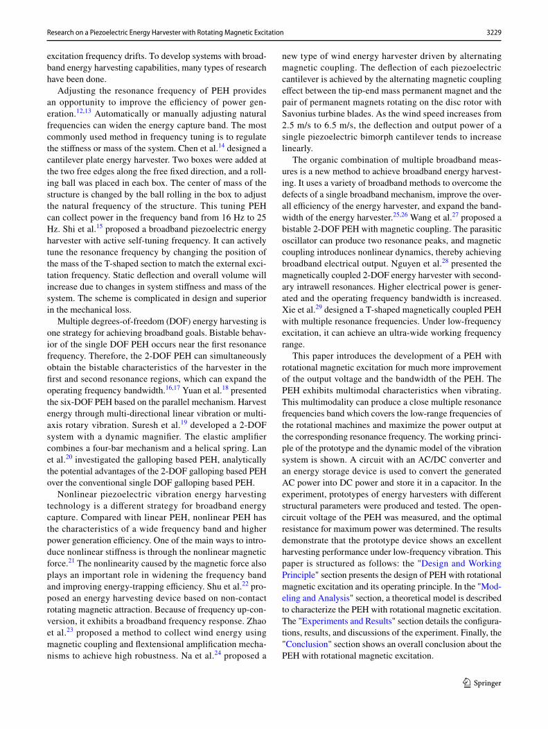
revolving host is penetrated by the optical axis and placed on the support frame. The pedestal and the support frame are fixed on the ocular platform by bolts. The revolving host, the intermediate-mass, and the pedestal are made of PLA mate-rial in an FDM 3D printer (JGAURORA). The parameters of the prototype are presented in Table I.
The experimental setup of the PEHS is illustrated in Fig. 5. The servo controller adjusts the servo motor rotation speed. The servo motor drives the revolving host to rotate. The periodic magnetic repulsive force causes the RPB and APB to vibrate. The vibration of the RPB and APB causes the piezoelectric element to generate electrical energy. A
digital oscilloscope (DS4043 RIGOL) is utilized to moni-tor the output voltage of the PEHS. Experimental data are processed and drawn by data analysis software (Origin). The PEHS generates AC, which transforms into DC to change the sensor. With the aim to accumulate the harvested power for possible use as DC current, a rectifier bridge and an energy storage device are used in the REHS device, as shown in Fig. 6. The open-circuit voltage of the PEH was measured, and the optimal resistance for maximum power was estab-lished. The resistance box (ZX21e FUYANG) introduces a piezoelectric system and is attached in parallel to the system circuit. The voltage across the resistance is measured and the power is calculated.
Experiment results
To seek out resonance frequencies, it is necessary to observe open-circuit voltages at distinct rotation frequency. Figure 7 illustrates the relation between the output open-circuit volt-age and rotation frequency when the number of driving mag-nets is different. The experimental measurement was per-formed when the weight of the tip magnetic mass was 6 g, the radial excitation distance was 10 mm and the transverse excitation spacing was 2 mm. The number of driving mag-nets affects the magnitude of the external excitation force of the piezoelectric cantilever in a rotation period. If the number of driving magnets is small, the piezoelectric can-tilever is excited less frequently in one rotation period, and the deformation is not large. More driving magnets causes too many excitation times in the same cycle, and the buffer time of the piezoelectric cantilever is less. In both cases, the open-circuit voltage output by the piezoelectric energy harvesting device is relatively small. The PEH has the best power generation effect with two driving magnets. As shown in Fig. 7, the PEHS generates three separate resonance fre-quencies. There are three peaks of voltage at 3 Hz, 7 Hz, and 12 Hz, respectively. The three peaks of the output voltage of the PPB are 39.06 V, 35 V, and 33.75 V. The three peaks of the output voltage of the APB are 24.04 V, 26.25 V, and 24.68 V.
In the experimental environment, the first resonance frequency is 3 Hz, the weight of the tip magnetic mass is 6 g, and the radial excitation distance is 10 mm. The PEHS introduces a resistance box to measure the voltage across the resistance and obtain the power. Figure 8a and c indicate the effect of resistance on the RMS voltage with different numbers of the driving magnets. The RMS voltage increases as the resistance increases. The maximum voltage across the resistance appears when there are two driving magnets. Because there are many excitations in the same cycle, the RPB is stressed multiple times and the vibration range is large. However, if there are too many excitations in the same cycle, the RPB will not respond and will lag. The maximum
Table I The parameters of the prototype
Parameter Value
Piezoelectric elementLength lp 0.04 mWidth bp 0.015 mHeight hp 0.0002 mDensity �
p7700 kg/m3
Young’s modulus Ep 70 GPaCoupling coefficient d31 −285 × 10−12 C/NThe copper substrateLength ls 0.06 mWidth bs 0.015 mHeight hs 0.0003 mDensity �
s7800 kg/m3
Young’s modulus Es 200 GPaRectangular permanent magnetHeight A 0.003 mHeight B 0.004 mHeight C 0.005 mVolume A V1 0.0000006 m3
Volume B V2 0.0000008 m3
Volume C V3 0.000001 m3
Residual flux density Br 1.2 T
Fig. 5 Experimental setup of the PEHS.

3234 Z. Wang et al.
1 3
voltages of the PPB and the APB are 33.44 V and 19.17 V, respectively.
Figure 8b and d shows the effect of resistance on the average power with different numbers of driving magnets. The average power of the PEHS changes as the resistance increases, showing a trend of increasing first and then decreasing. The maximum average power of the PEHS occurs when there are two driving magnets. The PPB out-put average power is 3.56 mW with a resistance of 125 KΩ. The APB output average power is 2.43 mW with a resistance of 75 KΩ.
To adjust the natural frequency of PEH with rotational magnetic excitation, the influence of the different weights of cutting-edge mass magnets on power generation perfor-mance was tested. Figure 9 shows the output voltage ver-sus the rotation frequency when the weight of the tip mass magnet is different. The experimental measurement was performed with 10 mm radial excitation interval and two driving magnets. PEH holds the largest open-circuit voltage when the weight of the tip magnetic mass is 5 g. There are three peaks of voltage at 5 Hz, 8 Hz, and 12 Hz, respec-tively. The three peaks of the output voltage of the PPB are
Fig. 6 The circuit schematic diagram of the system.
Fig. 7 The open-circuit voltage versus rotation frequency with different numbers of driving magnets: (a) the PPB, and (b) the APB.

3235Research on a Piezoelectric Energy Harvester with Rotating Magnetic Excitation
1 3
47.49 V, 57.81 V, and 38.75 V. The three peaks of the output voltage of the APB are 25.94 V, 28.56 V, and 17.65 V.
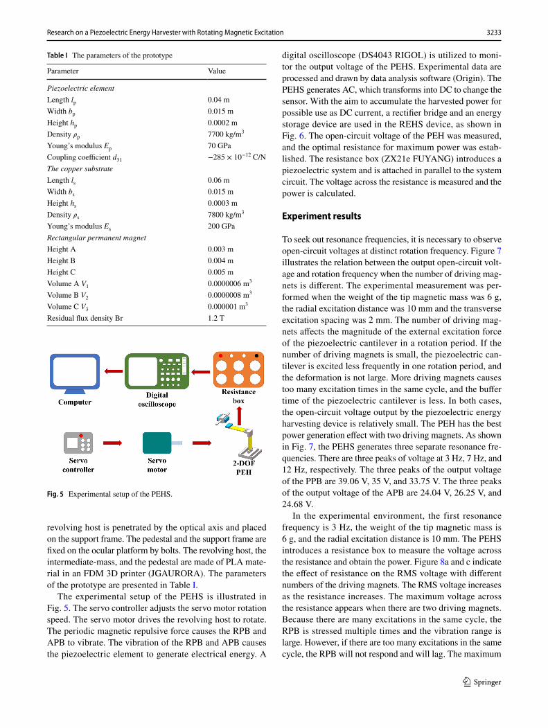
In the experimental environment, the first resonance fre-quency is 3 Hz, two driving magnets, and the radial excita-tion distance is 10 mm. Figure 10a and c indicates the effects of resistance on the RMS voltage at different weights of the tip magnetic mass. The RMS voltage increases as the resist-ance increases. The maximum voltage across the resistance appears when the weight of the tip magnetic mass is 5 g. The maximum voltages of the PPB and the APB are 46.43 V and 20.84 V, respectively.
Figure 10b and d shows the effects of resistance on the average power at the different weight of the tip magnetic mass. The average power of the PEHS changes as the
resistance increases, showing a trend of increasing first and then decreasing. The open-circuit voltage output from PEH is maximum when the weight of the tip magnetic mass is 5 g. The PPB output average power is 10.51 mW with a resist-ance of 125 KΩ. The APB output average power is 2.92 mW with a resistance of 75 KΩ.
The distance between magnets has a critical effect on the behavior of the system. Figure 11 displays the relationship between the output voltage of the PEHS and the rotation frequency when the radial excitation pitch is different. The experimental environment is that the weight of the tip mag-net is 5 g and there are two driving magnets. The magnetic force can be tailored by changing the radial excitation inter-val. The repulsive magnetic force decreases as the radial
Fig. 8 Resistance on the RMS voltage and the average power with different numbers of driving magnets: (a) and (b) the PPB; (c); and (d) the APB.

3236 Z. Wang et al.
1 3
separation of the two rectangular magnets increases. The magnitude of the voltage output by the PEHS is related to the vibration amplitude of the RPB. The open-circuit volt-age can be adjusted by changing the radial spacing of the two rectangular magnets. Arising out of the brittleness of the piezoelectric element, the radial excitation pitch can be limited indefinitely. The maximum value of the open-circuit voltage of the PEHS occurs at a radial excitation interval of 8 mm. There are three peaks of voltage at 5 Hz, 8 Hz, and 12 Hz, respectively. The three peaks of output voltage of the PPB are 49.37 V, 63.24 V, and 43.12 V. The three peaks of output voltage of the APB are 28.49 V, 30.38 V, and 32.81 V.
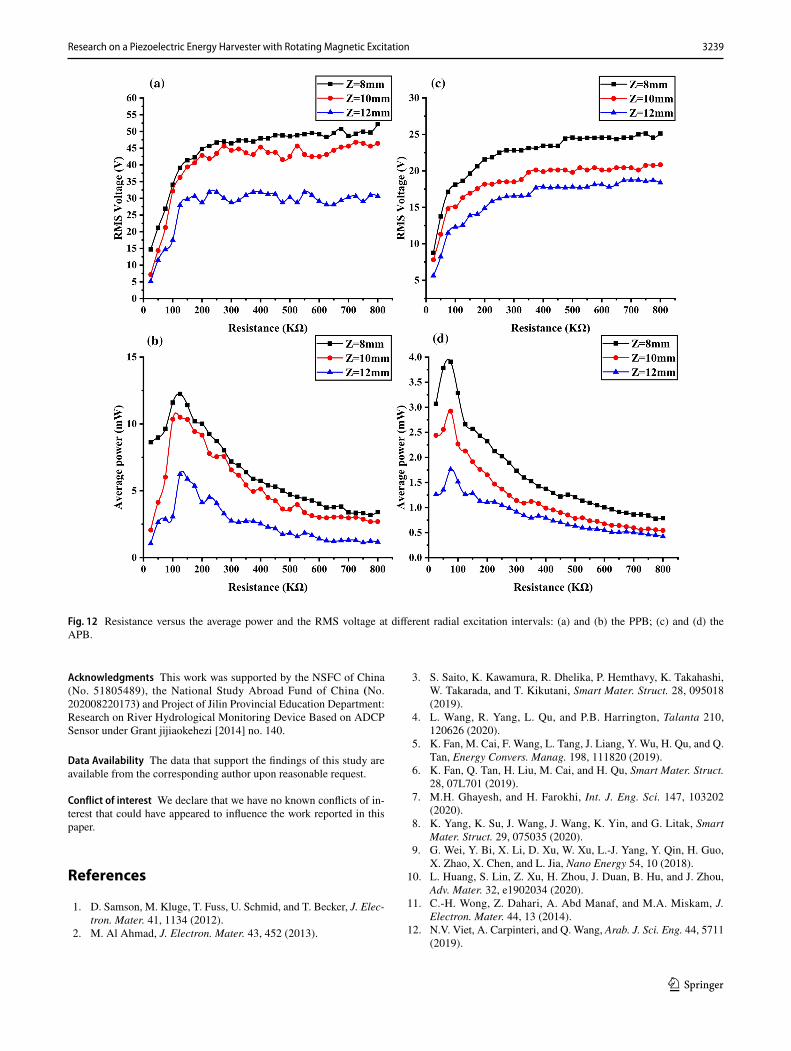
In the experimental environment, the first resonance fre-quency is 3 Hz, two driving magnets, and the weight of the tip magnetic mass is 5 g. Figure 12a and c shows the rela-tionship between the RMS voltage and the resistance when the different radial excitation interval. The RMS voltage increases as the resistance increases. The maximum volt-age across the resistance appears when the radial excitation interval is 8 mm. The maximum voltages of the PPB and the APB are 50.19 V and 25.12 V, respectively. Figure 12b and d indicates the effects of resistance on the average power at different radial excitation intervals. The average power of the PEHS changes as the resistance increases, displaying a trend of increasing first and then decreasing. The open-cir-cuit voltage output from PEH is maximum when the radial excitation interval is 8 mm. The PPB output average power is 12.24 mW with an external resistance of 125 KΩ. The APB output average power is 3.92 mW with a resistance of 75 KΩ.
Conclusions
This paper designs a PEH with rotational magnetic exci-tation in rotational motion, which can give rise to high voltage at low rotational frequency and produce multiple resonance peaks. The working principle of the prototype and the dynamic model of the vibration system is shown. A circuit with an AC/DC converter and an energy storage device is used to convert the generated AC power into DC power and stores it in a capacitor. In the experiment, prototypes of energy harvesters with different structural parameters were produced and tested. The open-circuit voltage of the PEH was measured, and the optimal resist-ance for maximum power was determined. The PEH with two driving magnets, 5 g tip magnetic mass, and 8 mm radial excitation distance has the best power generation effect. When the rotation frequency is 8 Hz, the maximum open-circuit voltages of the PPB and the APB is 63.24 V and 30.38 V, respectively. The PPB and the APB get the maximum power when the external resistance is 125 KΩ and 75 KΩ, respectively. The maximum output average power of the PPB and the APB is 12.24 mW and 3.92 mW, respectively. At the maximum power of the PPB and the APB, the voltage across the resistance is 39.12 V and 17.12 V, respectively. The proposed energy harvester can achieve a wide bandwidth of speed response and achieve high output performance with a small excitation force. This proves the great potential of the collector in broad-band rotational energy harvesting applications, such as tire condition monitoring, environmental monitoring, and condition monitoring of rotating machinery.
Fig. 9 The open-circuit voltage versus rotation frequency with different weight of the tip magnetic mass: (a) the PPB, and (b) the APB.
3237Research on a Piezoelectric Energy Harvester with Rotating Magnetic Excitation
1 3
Fig. 10 Resistance versus the RMS voltage and the average power at the different weight of the tip magnetic mass: (a) and (b) the PPB; (c) and (d) the APB.

3238 Z. Wang et al.
1 3
Fig. 11 The output voltage versus rotation frequency at different radial excitation intervals: (a) the PPB, and (b) the APB.
3239Research on a Piezoelectric Energy Harvester with Rotating Magnetic Excitation
1 3
Acknowledgments This work was supported by the NSFC of China (No. 51805489), the National Study Abroad Fund of China (No. 202008220173) and Project of Jilin Provincial Education Department: Research on River Hydrological Monitoring Device Based on ADCP Sensor under Grant jijiaokehezi [2014] no. 140.
Data Availability The data that support the findings of this study are available from the corresponding author upon reasonable request.
Conflict of interest We declare that we have no known conflicts of in-terest that could have appeared to influence the work reported in this paper.
References
1. D. Samson, M. Kluge, T. Fuss, U. Schmid, and T. Becker, J. Elec-tron. Mater. 41, 1134 (2012).
2. M. Al Ahmad, J. Electron. Mater. 43, 452 (2013).
3. S. Saito, K. Kawamura, R. Dhelika, P. Hemthavy, K. Takahashi, W. Takarada, and T. Kikutani, Smart Mater. Struct. 28, 095018 (2019).
4. L. Wang, R. Yang, L. Qu, and P.B. Harrington, Talanta 210, 120626 (2020).
5. K. Fan, M. Cai, F. Wang, L. Tang, J. Liang, Y. Wu, H. Qu, and Q. Tan, Energy Convers. Manag. 198, 111820 (2019).
6. K. Fan, Q. Tan, H. Liu, M. Cai, and H. Qu, Smart Mater. Struct. 28, 07L701 (2019).
7. M.H. Ghayesh, and H. Farokhi, Int. J. Eng. Sci. 147, 103202 (2020).
8. K. Yang, K. Su, J. Wang, J. Wang, K. Yin, and G. Litak, Smart Mater. Struct. 29, 075035 (2020).
9. G. Wei, Y. Bi, X. Li, D. Xu, W. Xu, L.-J. Yang, Y. Qin, H. Guo, X. Zhao, X. Chen, and L. Jia, Nano Energy 54, 10 (2018).
10. L. Huang, S. Lin, Z. Xu, H. Zhou, J. Duan, B. Hu, and J. Zhou, Adv. Mater. 32, e1902034 (2020).
11. C.-H. Wong, Z. Dahari, A. Abd Manaf, and M.A. Miskam, J. Electron. Mater. 44, 13 (2014).
12. N.V. Viet, A. Carpinteri, and Q. Wang, Arab. J. Sci. Eng. 44, 5711 (2019).
Fig. 12 Resistance versus the average power and the RMS voltage at different radial excitation intervals: (a) and (b) the PPB; (c) and (d) the APB.

3240 Z. Wang et al.
1 3
13. R. Del-Rio-Ruiz, J.J. Echevarria, X. Eguiluz, J.-M. Lopez-Garde, and J. Legarda, Electronics 9, 79 (2020).
14. C. Lihua, X. Jiangtao, P. Shiqing, and C. Liqi, Smart Mater. Struct. 29, 075001 (2020).
15. G. Shi, Y. Yang, J. Chen, Y. Peng, H. Xia, and Y. Xia, Smart Mater. Struct. 29, 055023 (2020).
16. M. Aramaki, T. Yoshimura, S. Murakami, K. Kanda, and N. Fujimura, Appl. Phys. Lett. 114, 133902 (2019).
17. C.K. Thein, F.M. Foong, and Y.-C. Shu, Mech. Syst. Signal Pro-cess. 132, 232 (2019).
18. G. Yuan, and D.H. Wang, Smart Mater. Struct. 26, 035022 (2017). 19. K. Suresh, K. Shankar, and C. Sujatha, Smart Mater. Struct. 28,
115016 (2019). 20. C. Lan, L. Tang, G. Hu, and W. Qin, Smart Mater. Struct. 28,
045018 (2019). 21. L. He, Z. Wang, X. Wu, Z. Zhang, D. Zhao, and X. Tian, Smart
Mater. Struct. 29, 055043 (2020). 22. Y.C. Shu, W.C. Wang, and Y.P. Chang, Smart Mater. Struct. 27,
125006 (2018). 23. L.-C. Zhao, H.-X. Zou, G. Yan, F.-R. Liu, T. Tan, K.-X. Wei, and
W.-M. Zhang, Energy Convers. Manag. 201, 112166 (2019).
24. Y. Na, M.-S. Lee, J.W. Lee and Y.H. Jeong, Appl. Energy 264, 114710 (2020).
25. L. Xiong, L. Tang, and B.R. Mace Appl. Phys. Lett. 108, 203901 (2016).
26. S. Sun, and P.W. Tse, Mech. Syst. Signal Process. 114, 467 (2019). 27. H. Wang, and L. Tang, Mech. Syst. Signal Process. 86, 29 (2017). 28. Nguyen, M.S., Yoon, Y.-J., and Kim, P., Int. J. Precis. Eng.
Manuf. Green Technol. 6(3):521 (2019). 29. Z. Xie, S. Zhou, J. Xiong, and W. Huang, J. Intell. Mater. Syst.
Struct. 30, 3136 (2019). 30. Q. He, Y. Xu, S. Lu, and Y. Shao, Meas. Sci. Technol. 28, 037002
(2017). 31. Z. Zhao, T. Wang, B. Zhang, and J. Shi, Math. Probl. Eng. 2019,
1 (2019). 32. A. Abdelkefi, and N. Barsallo, J. Intell. Mater. Syst. Struct. 25,
1771 (2014). 33. G. Zhou, Z. Li, Z. Zhu, B. Hao, and C. Tang, IEEE/ASME Trans.
Mechatron. 24, 700 (2019).
Publisher’s Note Springer Nature remains neutral with regard to jurisdictional claims in published maps and institutional affiliations.