ref qa process 12-1-15 handouts - home | northeast solar ... · pdf filesized to protect...
TRANSCRIPT

12/3/2015
1
December 1, 2015
The Solar Quality Assurance ProcessAn Overview for RI REF Installers
Presented by:Matt Piantedosi
CADMUS
Agenda• Overview of the RI REF Quality Assurance (QA) system
– Onsite inspections/reports– Self‐inspection reports– Current inspection results as of today
• RI Renewable Energy Growth (RE Growth) Program Requirements:– Electrical code and safety considerations
• PV Violations & Inspection Techniques– Based on the 2014 National Electrical Code
12/3/2015 2

12/3/2015
2
Outlining the QA Process
• Conduct inspections of all completed projects– Installer status– Special requests
• Schedule• Inspect
– Inspection Report– Corrective Action Report
• Summarize– MS Excel data– Monthly summary reports
12/3/2015 3
PV Quality Evaluation and Scoring Tool (PVQUEST)
12/3/2015 4

12/3/2015
3
Inspection Summary Tools
• Installer Summary Reports
– Most frequent installation issues
– Summary of inspection results by project
• Issue Frequency Report
– Program‐wide most common issues
– Installers needing support on most common issues
12/3/2015 5
Inspection Elements• What part of the system did the issue occur in?
• Inspectors have a custom checklist for each Inspection Element
• Installers know exactly where we found the issue and can better understand correction action requirements, taking faster action to address the findings
12/3/2015 6
‐Array‐String Inverter/ Microinverter‐TransformerlessInverter‐DC Disconnect‐AC Disconnect‐Load Side‐Connection/Supply Side Connection
‐Battery Backup‐Production MeterSubpanel‐DC Combiner/AC Combiner‐Junction Box‐Optimizer

12/3/2015
4
Example: Grounded Conductor Marking
12/3/20157
Text in body of report, photo stored in appendix
Text and photos stored together in report, organized by inspection element and type of action required by installer
Inspection Fields
12/3/2015 8
Grounding electrode conductor is sufficiently sized per NEC 690.47(C)
Grounding electrode conductor is properly bonded to the main premise grounding electrode system per NEC 690.47
PV backfeed breaker rating size is properly sized to protect circuit conductors Per 690.8(B)(1)
PV backfeed breaker is sufficiently sized to prevent nuisance tripping per NEC 690.8(B) and or 310.15

12/3/2015
5
Scoring
• 5‐point scale• Based on quantity of issues observed in each defect
category– Failure will require major or critical issues– Minor/incidental issues will result in scores of 3‐4
12/3/2015 9
Defect Category
Scenario 1 2 3 4 5 6 7 8 9 10
Incidental 2 3 3 0 0 0 2 0 3 1
Minor 1 1 2 0 0 1 0 2 2 1
Major 2 0 1 0 1 0 0 0 0 0
Critical 0 0 0 1 0 0 0 0 0 0
Overall Report Score 1 4 2 1 2 4 5 4 3 4
Old Scoring Matrix 1 4 2 1 2 4 5 4 4 4
Defect Category Observations
12/3/2015 10
PVQUEST Inspection Report Violations
Score Classification DescriptionRecommended Rebate Issuance Timeframe
5 No Issues No issues identified on site.Immediately Following
Inspection
4 Incidental
Issues not expected to impact system operation or safety. Examples: Installation debris left onsite, poor wire management, missing or incomplete labels, and installed equipment not matching program records but considered equivalent.
Immediately Following Inspection
3 Minor
Issues that pose a mid‐to long‐term risk of system failure or safety hazard.Examples: Bonding neutral to ground in a meter enclosure, insufficient clearance around boxes, undersized circuit protection, and improperly supported conductors.
Following Confirmation of Correction
2 Major
Issues deemed likely to impact system performance or safety in the short‐term, though not an immediate hazard. Examples: Missing equipment grounding, module microfractures, missing or undersized grounding electrode conductor, improperly secured PV modules, and missing or inadequate thermal expansion joints in long conduit runs.
Following Confirmation of Correction*
1 Critical
Issues that pose an immediate risk of system failure and/or safety hazard. Systems are often shut down during the inspection due to safety concerns. Examples: Exceeding current limits on busbars or conductors, exceeding inverter voltage limits, and use of non‐DC rated equipment in DC circuits.
Following Confirmation of Correction*

12/3/2015
6
Outputs of the QA Process
12/3/2015 11
Inspection Report• PDF Format• General Information
• Site Info• Installer Info• QA Score• Operational status
• Administrative Compliance• Equipment Verification• TSRF
• Program and Code Compliance• NEC• REF Minimum Technical Requirements
• Includes all issues found:• Corrective Action Required• Best Practice Recommendations• Issues Corrected Onsite
Outputs of the QA Process
12/3/2015 12
Corrective Action Report (CAR)• MS WORD Format• Lists ONLY issues requiring action by
installer• For each item, includes:
• Program Requirement• Program Deficiency• Inspector Comments
• Provides space/format for installer to respond:
• Installer Response (text)• Photos of Corrections Made (photos)• Signature lines for host customer and
installer representative

12/3/2015
7
Sample CAR Item
13
Violation ID (from report)
Requirement
Deficiency description
Inspector additional comments (if any)
Installer response line
Placeholder for correction photo(s)
CAR Items: ‐‐‐‐‐‐‐‐‐‐‐‐‐‐‐‐‐‐‐‐‐‐‐‐‐‐‐‐‐‐‐‐‐‐ A_EL12 Requirement: Conductors properly supported Deficiency Description: Circuit conductors are sagging and in contact with the roof and/or not supported and secured at least every 4.5' and within 12" of every outlet box, junction box, cabinet, or fitting, in violation of NEC Articles 338.10(B)(4) and 334.30. Inspector Comments: West side of array, multiple locations. Installer Response: Photos of Corrections Made: ‐‐‐‐‐‐‐‐‐‐‐‐‐‐‐‐‐‐‐‐‐‐‐‐‐‐‐‐‐‐‐‐‐‐
How Does the CAR Work?
• CAR issued for scores of 1 to 4, and will come via email with the inspection report
• Installer must use CAR to submit relevant proof of corrective action taken:– Photos– Comments/description– Dispute
• CAR corrections should be made as soon as feasible
12/3/2015 14

12/3/2015
8
Self‐Inspection Reports
• Avenue for qualified installers to expedite inspection process
– Including electrical subcontractors for a specific installer
• Expedited status can be granted by REF based on a number of consistent, high quality inspections
• An average score of > 4 must be maintained to continue as an expedited installer
12/3/2015 15
Self‐Inspection Memo
• Cadmus inspector reviews a report prepared and submitted by system installer
• Reports are scored using same scoring metric as field inspections
• Cadmus will still inspect 10% of sites submitted by an expedited installer
12/3/2015 16

Commerce Rhode Island SolarPhotovoltaic Self Inspection Report
InstructionsThe questions in this self inspection report are intended to collect key system installation
characteristics, including photographs, which will allow Commerce Rhode Island staff and contractors to
conduct a reasonable due diligence review, as a substitute for an onsite inspection. This report includes
a self inspection checklist and a descriptive photograph sheet. Installers wishing to complete a self
inspection must fill out all applicable fields. In cases where multiple pieces of equipment (e.g., two
different types of PV modules) are used, please copy/paste the relevant information table and fill it out
for both sets of equipment. Installers are encouraged, but not required, to attach an as built electrical
design drawing to this report.
Once completed, please submit this form in PDF format via email to [email protected]. For
technical questions on completing this self inspection report, contact [email protected].
System InformationGrant Number 1234567
System Owner Last Name Homeowner
Installation Company Solar Company
Installer Last Name Mr. Solar
Person Completing This Report Matt Piantedosi
Phone 617 673 7102
Email [email protected]
Report Date 2/12/2015
Self Inspection Checklist
Array and PV ModulesInspection Item Value
Module Quantity 23
Module Manufacturer SolarWorld
Module Model Number SW 275 mono black
Modules per String (or per circuit formicroinverters)
12, 13
Number of Strings per Input Circuit 2
Conductor Size/Insulation Type #10 AWG THHN/THWN 2
Describe grounding method for module frames,rails, metal roofing, and other metallic hardware(NEC 690.43).
Racking listed to bond module frames, #10 solidcopper on each rail.
If WEEBs (or equivalent) used, indicatenumber used per module.
N/A
SAMPLE
tioio
affaff andand co
tion.tion. ThisT reporto
ishingshing tot complpleteete aa self
ces off equipmentequipment (e.g.,(e two
ant informationtion tabletab and filll itit ouou
equired,q to attach ann asas builtb electrelectr
viavia emailemail to [email protected]@commerceri
PLonn report,repo contactonta [email protected]@C
12345671234567
MP
MPHomeownermeown
MP
MPSolarSo CompanyCompan
MP
MPMr.Mr. SolarS
MP
MP
ortrt Mattatt PiantPiaMM617 67367MMMattMMAMM22
AMAMMspection ChecklistChecklist
rayay andan PVPVModuleslesInspectionspec Itemem
SAModuleodule QuantityQuantitySA
duleule ManufacturerManufacturerSSe ModeldSNumbermberSperper StringString (o(ors)SS
2
Conductors supported and protected fromdamage.
Yes No N/A
All enclosures and splicing means rated foroutdoor/wet location use (e.g., no indoor wirenuts).
Yes No N/A
All roof penetrations are properly flashed andsealed (note that sealant is a supplement, not areplacement, to flashing).
Yes No N/A
DC conduit labeled as containing PV circuits (NEC690.31(G)(3) and 690.31(G)(4)).
Yes No N/A
DC DisconnectInspection Item Value
Max DC Ratings Voltage 600V Current 30A
Location Inverter Integrated
DC disconnect located near inverter and readilyaccessible.
Yes No N/A
DC characteristics label present (NEC 690.53). Yes No N/A
Disconnects all ungrounded conductors (notethat ungrounded arrays must disconnect bothpositive and negative conductors).
Yes No N/A
String Inverter (includes Transformerless units)Inspection Item Value
Quantity 1
Manufacturer SolarEdge
Model Number SE6000A US
AC Conductor size/insulation type #6 AWG THHN/THWN 2
DC Arc Fault Circuit Interrupter (AFCI) device Inverter Integrated Other
If Other, enter manufacturer/model
Rapid Shutdown device Inverter Integrated Other
If Other, enter manufacturer/model
Continuous grounding electrode conductororiginates at designated inverter terminal.
Yes No N/A
Microinverter/DC OptimizerInspection Item Value
Quantity 23
Manufacturer SolarEdge
Model Number P300
Inverter Breaker/Fuse Current Rating (A) N/A (for Optimizers)
AC Disconnect/AC CombinerInspection Item Value
Max Enclosure Ratings (AC) Voltage 240V Current 30A
Location(s) Inverter Integrated
Disconnect located near inverter and readilyaccessible.
Yes No N/A
AC characteristics label present (NEC 690.54). Yes No N/A
Disconnects all ungrounded conductors. Yes No N/A
SAMundingng electrodeelectrode conductorconductordesignatedted inverterter terminal.terminaAMpterer M
PLEECurrentCu 30A0A
EEENo N/AN
LELELLE
No N/AN/A
LLELELLENo N/AN/ALLELEPLPLPLLEerlesserless units))ValueVa PL
MP11
MP
MPSolarEdgearEdge
MP
MPSE6000ASE6000A USUS
MP
MPypepe #6#6 AWGA THHTHH
MP
MP
(AFCI)(AFCI) devicede MnverteMManufacturer/modelcturer/modelMMce MI
AMMnterter manufacturer/modelmanufacturer/model
AMMAMAinverter/DCinverte OptimizerOptimpectionpectio Itemem
SAQuantityuant
SAManufactureranufacturerSA
odeldel NumberNumbSSer SBreaker/Fuseaker/Fuse CuCuSSSnnect/Anect/S

3
Interconnection (Supply Side)Inspection Item Value
PV Service Disconnect Location Outdoor West wall of house
Enclosure Rating Voltage 240V Current 100A
Fuse Rating Voltage 250V Current 35A
Directories/labeling present on all servicedisconnects per NEC 230.2(E), 230.70(B), and690.56(B).
Yes No N/A
Grounded conductor bonded to enclosure (NEC250.24(C)).
Yes No N/A
Utility conductors connected to “Line” side ofdisconnecting means.
Yes No N/A
Interconnection (Load Side)
Photos RequiredFull Array Image(s)Include all modules for verifying system capacity.
Notes: SAMPLE
NN
EEEELELEotes:tes:
LE
S
4
Array Mounting/Flashing DetailClose shot of mounting bracket, connection to roof, and associated use of flashing/sealant.
Notes:
Under Array Wire Management
Notes:
Array GroundingShow typical grounding hardware installation.
Notes:
SAMding Acal AMPLELEPLE
groundingng hardwarehardware installationinstallatioAMSA

5
Wiring of Junction and/or Combiner BoxShow splice/termination method and conductor fittings.
Notes:
Balance of System (BOS) Overview PhotosShow general location/configuration of DC disconnect, inverter, production meter, panelboards, andother co located equipment.
SM
PL
DCC disconnect,disconnect, inverter,inverte productionPLEPLM
P6
Notes:
SAMPLE

7
DC Disconnect ExteriorShow nameplate/labeling details.
Notes: Disconnect integrated in inverter
DC Disconnect InteriorShow wiring details.
Notes:
SAMPLE
ed inin inverterinverter
AMAM8
String Inverter ExteriorShow sufficient detail to verify labeling.
Notes:
String Inverter InteriorShow wiring terminations.
Notes: See DC Disconnect Interior
AC Disconnect ExteriorShow nameplate/labeling details.
Notes: See DC Disconnect Exterior
Notes:otes SA
ringng InverterInverter InteriorrSwiring terminations.tionSASDiS

9
AC Disconnect InteriorShow wiring details.
Notes: See DC Disconnect Interior
Production Meter InteriorShow wiring of production meter enclosure.
Notes:
Load Side Interconnection Main Service Panel Exterior (Door Closed)Show labeling detail, if applicable.
N/A
Notes:
Load Side Interconnection Main Service Panel (Door Open)Show labeling detail and backfeed breaker.
N/A
Notes: SAAA
SAMPLE
e Interconnectiontion MainMain Serviceice PaP
SAlabelinglabeling detail,de if applicable.applica
SANotes:otes: SASdd SideSide InterconnectionInterconnectioSabelingn detailil andandSSS
10
Supply Side InterconnectionShow service entrance conductor tap detail.
Notes:
Supply Side Interconnection Disconnect ExteriorShow labeling/nameplate detail.
Notes:
SAMP
MPLterior
MPPLEPL
MP

11
Supply Side Interconnection Disconnect InteriorShow wiring/fuse details.
Notes:
SAMPLE

12/3/2015
12
Self‐Inspection Corrective Action
• Observed violations and corrections are listed on the memo, and sent to installer for response, similar to CAR process
• Photos can be added to table in word document
12/3/2015 23
Current Results from Commerce RI Inspections
PV Inspection Results: Systems by Severity of Issues Found
N=159
24
7%10%
18%
38%
27%
Renewable Energy Fund Inspection Violations as of 12/1/15
Critical Major Minor Incidental No Issues

12/3/2015
13
New Interconnection Requirements RI Renewable Energy Growth (RE Growth) Program ‐ Residential
• Section 4 of the RE Growth Program Tariff document (RIPUC No. 2151) outlines a metering configuration
• Solar PV installation shall be on a new utility meter
• Absolutely no connection to load side of existing utility meter
• Intended for the installer to replace existing utility meter enclosure with multi‐gang enclosure (i.e. replace existing 1‐gang with new 2‐gang)– Existing meter is utilized for existing service/loads
– New PV system/meter is a new “tenant” in the building
• Consideration should be taken for new disconnect/fuse location and marking…
25
Cadmus interpretation to:
CADMUS
New Interconnection Requirements RI Renewable Energy Growth (RE Growth) Program ‐ Residential
• Traditional Method Example– Supply‐side interconnection
• New Method Example
Cadmus interpretation to:
inside Main Service
Panelboard
Existing Utility Meter
PV Interconnection
Point
Utility PV
Meter
PV Inverter
outside
inside Main Service
Panelboard
Utility Meter
Fused PV Disconnect
Fused PV Disconnect
PV Inverter
PV Interconnection Conductors
MAX 10 FEET
Requires Disconnect Directory per690.56(B)
Requires Disconnect Directory per690.56(B)

12/3/2015
14

12/3/2015
15
Examples of Tapped SE ConductorsThe Wrong Way…
12/3/2015 30Courtesy of Mark Elsner, Town of Plymouth

12/3/2015
16
Examples of Tapped SE ConductorsThe Wrong Way…
12/3/2015 31CADMUS
Top PV Violations & Inspection Techniquesfrom the Sun to the Grid…
32

12/3/2015
17
Array Violations
33
Equipment Grounding System2014 NEC Article 690.43 / 250.4
• Approximately 15% of all inspections contain issues with Array equipment grounding
34CADMUS

12/3/2015
18
Equipment Grounding System2014 NEC Article 690.43 / 250.4(A)(5)
• All metal parts “likely to become energized”– Module frames
– Racking
– Metal roof
– Metal conduit/enclosures
• Low impedance ground‐fault current path back to the source or ground detector– Inverter or AC panelboard
35
Equipment Grounding System2014 NEC Article 690.43 / 250.4
• Article 250.4(A)(5) / 250.4(B)(4)
– The earth shall not be considered as an effective ground‐fault current path
– You can’t “just drive a ground rod”
36CADMUS

12/3/2015
19
Connection of Grounding and Bonding Equipment2014 NEC Article 250.8
• Listed pressure connectors
• Terminal bars
• Exothermic welding
• Machine screws – Standard or thread‐forming
– Engage 2 or more threads
– Secured with a nut
• Listed assembly/means– Read the instructions!!!
37
Module Frame Grounding2014 NEC Article 690.43
• Many methods per manufacturer’s instructions– Lay‐in lug
• Must be suitable for the environment in which it is installed– Contact with aluminum (usually tin‐plated copper)– Outdoor/wet locations (suitable for direct‐burial)
– Listed fitting• WEEB• Racking
– Plastic frame• No ground required
38

12/3/2015
20
Module Frame GroundingWrong Lugs – (Copper or Not Listed for Outdoor)
39CADMUS
Module Frame GroundingRight Fitting, Installed Wrong
40CADMUS

12/3/2015
21
41
Grounding the RackingWrong Screw (110.3(B) and 250.8)
CADMUS
Grounding the Racking2014 NEC Article 690.43
42
• Many methods per manufacturer’s instructions– Lay‐in lug
• Must be suitable for the environment in which it is installed
– Contact with aluminum (usually tin‐plated copper)
– Outdoor/wet locations (suitable for direct‐burial)
– Listed fitting• WEEB
– New racking‐integrated bonding• Check the model!
– Plastic (non‐metallic) racking• No ground required
CADMUS

12/3/2015
22
Grounding the RackingConsiderations
• Wire management
• Conductor type/material
• Size
• Splices
– Where permissible
– Not in lay‐in lugs
43
Grounding the RackingTrip Hazard
44CADMUS

12/3/2015
23
Common Array Violations
• DC conductors at array not properly supported and protected– Conductors shall be protected against physical damage (including those beneath array)
– Articles: • 300.4
• 338.10(B)(4)(b)
• 334.30
• 338.12(A)(1)
45
Approximately 25% of all inspections contain issues with conductor protection…
CADMUS 46

12/3/2015
24
CADMUS 47
CADMUS48

12/3/2015
25
CADMUS49
The Right Way…
CADMUS
PV conductors free from physical damage.50

12/3/2015
26
CADMUS
PV conductors supported from roof surface.
The Right Way…
51
CADMUS
CADMUS
End Clamp Too Close to Rail End
52
Most manufacturers specify at least ½” of space between the end clamp and the end of the rail to allow for thermal expansion and vibration.

12/3/2015
27
Measure Twice, Cut Once
53
PV Rainwater Collection System
54
1) No Flashing2) Lag Bolt not secure3) Probably missed the
rafter

12/3/2015
28
Conductors Entering BoxesNEC Article 314.17
• Conductors entering boxes shall be protected
• The raceway or cable shall be secured to such boxes and conduit bodies
55CADMUSCADMUS
Readily Accessible LocationsNEC Article 690.31(A)
• Ground‐mount arrays– In readily accessible
locations, conductors shall be guarded or installed in a raceway
• Language clarification to adopt standard practice
CADMUS
56

12/3/2015
29
PV conductors in readily accessible locations shall be installed in a raceway.
CADMUS57
PV conductors in readily accessible locations shall be guarded or installed in a raceway.
CADMUS
58

12/3/2015
30
The Right Way…
Readily accessible PV conductors properly guarded.
CADMUS59
Readily accessible PV conductors properly guarded.
CADMUS
The Right Way…
60

12/3/2015
31
Dissimilar MetalsBeyond the lugs…
61CADMUS CADMUS
Dissimilar MetalsBeyond the lugs…
62CADMUS

12/3/2015
32
Dissimilar MetalsBeyond the lugs…
63CADMUS
• Lay‐in lug– Must be suitable for the environment in which it is installed
• Outdoor/wet locations (suitable for direct‐burial)
64
Bonding BushingsRated for Outdoor Use?

12/3/2015
33
PV Output Violations
65
Common PV Output Violations
• Not properly sized for conditions
– 690.8 calculations
– 310.15 ampacity/temperature/conduit fill
• Not properly secured/supported
– Article 338.10(B)(4)(b) 334.30
• Not properly protected
– Article 338.12(A)(1)
66

12/3/2015
34
Unprotected PV output conductors.CADMUS
67
CADMUS
PV output conductors installed in conduit. 68
The Right Way…

12/3/2015
35
Common PV Output Violations
• Outdoor enclosures
– Not grounded in accordance with 250.8(A)
– Not installed “so as to prevent moisture from entering or accumulating…” in accordance with 314.15
– Penetrations not sealed, as required by 300.7(A)
– Indoor wire connectors, 110.3(B), 110.28
69
CADMUS
70

12/3/2015
36
CADMUS 71
CADMUS
Enclosures must be installed “so as to prevent moisture from entering or accumulating…” in accordance with 314.15 72

12/3/2015
37
CADMUS
Raceway must be sealed when passing between the interior and exterior of a building per 300.7(A) 73
74
Products in contact with conductor insulation should be rated for electrical applications. This is ONE example, there are many other products available.

12/3/2015
38
Common PV Output Violations
• PVC Expansion Fittings– Missing – Article 352.44
• Expansion fittings shall be provided where the length change is expected to be ¼ in. or greater in a straight run between securely mounted items:
– Boxes
– Cabinets
– Elbows
– Other conduit terminations
– Installed wrong
75
CADMUS
CADMUS

12/3/2015
39
The Right Way…
77
CADMUS
• Conductive materials enclosing conductors SHALL BE BONDED!– Plastic enclosure outside
– Metal inside
– Plastic DC disconnect
CADMUS
78
Bonding the RacewayNEC Article 250.4
CADMUSCADMUS

12/3/2015
40
• All PV systems with DC operating at 80 Volts or greater– Protected by listed “PV type” AFCI
• Or equivalent
CADMUS
79
DC AFCI ProtectionNEC Article 690.11
• All major brands NOW AVAILABLE– Inverters– Combiner boxes– Micro inverters (not required)
• Typically operate under 80 Volts DC
• CHECK THE MODEL!!!• Ensure AFCI mode is enabled
CADMUS
80
DC AFCI ProtectionNEC Article 690.11

12/3/2015
41
• PV system circuits on or in buildings shall include a rapid shutdown function:– 690.12(1) through (5)…
81
Rapid Shutdown of PV Systems on BuildingsNEC Article 690.12
• 690.12(1)– More than 10’ from an array
– More than 5’ inside a building
82
Rapid Shutdown of PV Systems on BuildingsNEC Article 690.12
CADMUSCADMUS

12/3/2015
42
• 690.12(2)– Within 10 seconds
• Under 30 Volts
• 240 Volt‐Amps (Watts)
– A typical module:
• ~250 Watts
• ~30 Volts
• 690.12(3)– Measured between:
• Any 2 conductors
• Any conductor and ground
83
Rapid Shutdown of PV Systems on BuildingsNEC Article 690.12
Source: UL.com
• 690.12(4)– Labeled per 690.56(B)
• Permanent plaque
• Location of all disconnecting means
84
Rapid Shutdown of PV Systems on BuildingsNEC Article 690.12

12/3/2015
43
• 690.56(C)
• Required even for microinverters!
85
Rapid Shutdown of PV Systems on BuildingsNEC Article 690.12
• Minimum 3/8” CAPSon Red
CADMUS
• 690.12(5)
– “Equipment that performs the rapid shutdown shall be listed and identified.”
86
Rapid Shutdown of PV Systems on BuildingsNEC Article 690.12

12/3/2015
44
• Intended to protect first responders
• Original proposal:
– Disconnect power directly under array
• Module‐level shutdown
• Compromise:
– Combiner‐level shutdown
87
About Article 690.12
Source: UL.com
• Open‐ended gray areas:
– Location of “rapid shutdown initiation method”
– Maximum number of switches
– Type of building
• Dwelling
• Commercial
88
About Article 690.12
CADMUS

12/3/2015
45
• Considerations:– Disconnect power within 10 seconds
– Inverters can store a charge for up to 5 minutes (UL 1741)
89
About Article 690.12
• What complies:– Microinverters
– AC modules
– DC‐to‐DC Optimizers/Converters
• May or may not depending on the model
90
About Article 690.12
CADMUS
CADMUS

12/3/2015
46
• What complies:– Exterior string inverters if either:
• Located within 10 feet of array
• Inside building within 5 feet
– “Contactor” or “Shunt Trip” Combiner Boxes/Disconnects• Must be listed for “Rapid Shutdown” as a system
– Many considerations & variations for full system compliance• Plans should be discussed with AHJ prior to installation
91
About Article 690.12
CADMUS
Inverter Violations
92
12/3/2015
47
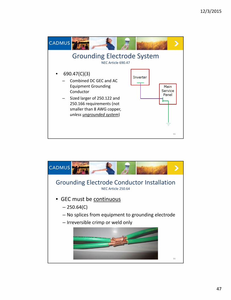
• 690.47(C)(3)
– Combined DC GEC and AC Equipment Grounding Conductor
– Sized larger of 250.122 and 250.166 requirements (not smaller than 8 AWG copper, unless ungrounded system)
93
Grounding Electrode SystemNEC Article 690.47
Grounding Electrode Conductor InstallationNEC Article 250.64
• GEC must be continuous
– 250.64(C)
– No splices from equipment to grounding electrode
– Irreversible crimp or weld only
94

12/3/2015
48
Disconnection of PV EquipmentNEC Article 690.15
• “Means shall be provided to disconnect equipment, such as inverters, batteries, and charge controllers, from all ungrounded conductors of all sources. If the equipment is energized from more than one source, the disconnecting means shall be grouped and identified.
95
Disconnection of PV EquipmentInside the “S” brand…
96
CADMUS
CADMUS
CADMUS

12/3/2015
49
Disconnection of PV EquipmentIn a Nutshell
• 690.15– Isolate inverter from all power
sources
• 690.17– DC disconnect requirements
• Externally operable• Simultaneously disconnect all ungrounded conductors
• Suitable for voltage and current (may or may not be “PV” type)
Some utilities require outdoor externally operable AC disconnect switches, but not the NEC.
97
CADMUS
Microinverter MountingBolt too long…
98CADMUS
Long bolts/hardware can cut into modules and short out. Extreme care should be taken to ensure module will not contact bolt under normal or weighted
conditions.

12/3/2015
50
Type NM CableNEC Article 334.12
• Prohibited in wet/damp locations
– Article 334.12(B)(4)
• Outdoor raceways are wet locations!
– Article 300.9
99
CADMUSCADMUSCADMUSCADMUS
Production Meter Violations
100

12/3/2015
51
Production Meter Violations• Article 250.24(A)(5)
– Neutral conductor bonded to frame
CADMUS101
Production Meter Violations• Article 110.3(B)
– Small conductors on lugs
102
CADMUSCADMUS

12/3/2015
52
PV Interconnection
103
• 705.12 Point of Connection
– (A) Supply Side
– (D) Load Side
104
Article 705.12
CADMUS

12/3/2015
53
Supply Side Interconnection NEC Article 705.12(A)
• Interconnection on utility side of main service disconnect
• Typically on customer side of utility meter– RE Growth program connection will
be on new utility meter
• “Second set” of service entrance conductors (Article 230)
• Utility conductors must be on line terminals of disconnect– These remain energized when
disconnect is opened (turned off) 105
CADMUS
Supply Side Interconnection Grounding Service‐Supplied Alternating‐Current Systems
• NEC Article 250.24(A)(1) – The GEC shall be made at any accessible
point from the load end of the:• Overhead service conductors
• Service drop
• Underground service conductors
• Service lateral
– To the terminal or bus to which the grounded service conductor is connected at the service disconnecting means
106CADMUS

12/3/2015
54
Supply Side Interconnection Disconnect Labeling and Grouping Example
• Interconnection inside main panelboard
– Supply side of main breaker
• Fused PV disconnect located outside
– Metal raceway between main panelboard and outdoor disconnect MAX 10 FEET per 705.31
• Panelboard and PV disconnect labeled per 705.10 and 705.12
• Article 690.56(B)
– Requires plaque in this situation
outside
inside
PV Interconnection Conductors
MAX 10 FEET
Fused PV Disconnect
Utility Meter
Main Service
PanelboardPV Inverter
107
Requires Disconnect Directory per690.56(B)
Requires Disconnect Directory per690.56(B)
Load Side InterconnectionNEC Article 705.12(D)
• Key sections include:1. Interconnection shall be made at dedicated OCPD2. Feeders, Taps, Busbar Interconnection3. Equipment shall be marked to indicate presence of all
sources
108CADMUS

12/3/2015
55
PV InterconnectionConsiderations…
• Terminal ratings should be followed:
– Conductor size
– Max conductors
109CADMUSCADMUS
Bus or Conductor Ampere Rating ‐ FeedersNEC Article 705.12(D)(2)(1)(a)
• Option (A)
• Feeder ampacity not less than sum of:– Primary source OCPD
– 125% of inverter current
110Source: IAEI.com

12/3/2015
56
Bus or Conductor Ampere Rating ‐ FeedersNEC Article 705.12(D)(2)(1)(b)
• Option (B)
• Feeder ampacity not less than primary source OCPD– Must add OCPD at interconnection
111Source: IAEI.com
Bus or Conductor Ampere Rating ‐ FeedersNEC Article 705.12(D)(2)(1)(b)
112Courtesy of Mark Elsner, Town of Plymouth
Existing conductors must be increased in size or
protected

12/3/2015
57
Bus or Conductor Ampere Rating ‐ BusbarsNEC Article 705.12(D)(2)(3)(a)
• Option (A) PV & Main less or equal to busbar
• Busbar ampacity not less than sum of:– Main OCPD
– 125% of inverter current
• PV breaker can be located anywhere113
Main Breaker100A
Busbar125A
100% of125A = 125A
125% PV Output18A
Main + PV = 118A
100% Busbar = 125A
118A feeds < 125A bus
Example:Inverter current = 14.4A14.4A x 125% = 18A
Bus or Conductor Ampere Rating ‐ BusbarsNEC Article 705.12(D)(2)(3)(b)
• Option (B) “120% Rule”
• 120% of busbar ampacity not less than sum of:– Main OCPD
– 125% of inverter current
• PV breaker must be at opposite end114
Main Breaker100A
Busbar100A
120% of100A = 120A
125% PV Output18A
Main + PV = 118A
120% Busbar = 120A
118A feeds < 120A bus
Example:Inverter current = 14.4A14.4A x 125% = 18A

12/3/2015
58
Bus or Conductor Ampere Rating ‐ BusbarsNEC Article 705.12(D)(2)(3)(c)
• Option (C) “AC Combiner Panelboard”
• Busbar ampacity not less than sum of:– All breaker ratings (PV or other loads)
– Excluding main OCPD
• Permanent warning label required115
Load Breaker20A
Busbar100A
PV Breakers80A total
Loads + PV = 100A
100% Busbar = 100A
100A loads & PV = 100A bus
Example:4 20A inverter breakers
4 x 20A = 80A
Wire Harness and Exposed Cable AFCI ProtectionNEC Article 705.12(D)(6)
• Intended for micro inverters
• Wire harness or cable output circuit rated:
– 240 Volts
– 30 Amps or less
• Not installed in a raceway, listed AFCI protection
– Circuit breaker, suitable for backfeed
116
CADMUS

12/3/2015
59
Wire Harness and Exposed Cable AFCI ProtectionNEC Article 705.12(D)(6)
Recommendation from the SEIA Codes and Standards Working Group and SolarABCs (http://www.solarabcs.org/) PV Industry Forum to remove 705.12(D)(6) from the 2017 Code. Why?
• No suitable devices are widely available on the market– Suitable for backfeed– 3‐pole, 3‐phase devices
• Requirements are not aligned with how Arc‐Fault protection as implemented for ac premises wiring 210.12
– Single phase 120 V circuits– Convenience outlets and zip cords– Outdoor circuits are exempted– Fire classified roof surface with PV modules evaluated for ignition
and flame spread
• Safety standards do not adequately cover PV applications (UL 1699)
– Backfeed– 3‐phase circuits– Nuisance tripping
117
Although double‐pole AFCI breakers are available, they are not suitable to be backfed, and would violate their listing in
this application.
CADMUS
PV System Labeling
• NEC Article 110.21(B)– Field Applied Hazard Marking shall meet the following
requirements: 1. The marking shall adequately warn of the hazard using effective
words and/or colors and/or symbols.
2. The label shall be permanently affixed to the equipment or wiring method and shall not be hand written.
Exception: Portions of the labels or markings that are variable, or that could be subject to change, shall be permitted to be hand written and shall be legible.
3. The label shall be of sufficient durability to withstand the environment involved.
118

12/3/2015
60
PV System Labeling
119690.31(G)(3) DC Conduit Label
690.13(B) PV System Disconnect
690.53 DC Power Source
690.54AC Power Source
690.17Disconnect Line/Load
Energized705.12(D)(3)
Multiple Sources
705.12(D)(2)(3)(b)PV Breaker
“Do Not Relocate”
690.56(B)Service Disconnect
Directory
Approximately 70% of all inspections contain issues with labeling…
DC Raceway LabelNEC Article 690.31(G)(3)
• On or inside a building
• New wording:
– Minimum 3/8” CAPS
on Red
120

12/3/2015
61
121
CADMUS
PV System DisconnectMoved to 690.13(B)
122CADMUS

12/3/2015
62
Disconnect Line/Load Energized690.17(E) Per
110.21(B)
ELECTRIC SHOCK HAZARDDO NOT TOUCH TERMINALS.
TERMINALS ON BOTH THE LINEAND LOAD SIDES MAY BE ENERGIZED IN THE
OPEN POSITION.
123
DC Power Source690.53
124
CADMUS
CADMUS

12/3/2015
63
DC Power SourceSolarEdge Application Notes
http://www.solaredge.com/files/pdfs/pv_power_source_labeling.pdf
125
DC Power SourceSolarEdge Application Notes
1. Rated maximum power point current
– Lower of following 2 values:
• Total STC DC power rating for all modules divided by nominal string voltage listed in item (2)
• Maximum input current rating of inverter
– For example:
• SE6000A‐US inverter w/ 7.28 kW array
• 7280W/350Vdc = 20.8A
• SE6000A‐US inverter max rating of 18A126
http://www.solaredge.com/files/pdfs/pv_power_source_labeling.pdf

12/3/2015
64
DC Power SourceSolarEdge Application Notes
127
2. Rated maximum power point voltage
– SolarEdge inverters operate on fixed voltage, determined by AC grid voltage:
• Single Phase Inverters– 208 Vac 325 Vdc nominal string voltage
– 240 Vac 350 Vdc nominal string voltage
– 277 Vac 400 Vdc nominal string voltage
http://www.solaredge.com/files/pdfs/pv_power_source_labeling.pdf
DC Power SourceSolarEdge Application Notes
128
3. Maximum system voltage– Modules not directly connected to DC output
circuit• When AC power is off, optimizer output is 1 Vdc per
optimizer
– During startup, voltage will be slightly higher than values in (2)
– SolarEdge labeling requirement:• All Single Phase Inverters
– 500 Vdc
http://www.solaredge.com/files/pdfs/pv_power_source_labeling.pdf

12/3/2015
65
DC Power SourceSolarEdge Application Notes
129
4. Maximum system current
– String current regulated by inverter
– Will never exceed max input current rating
– Optimizer output circuits limited to 15 Adc
– Inverters can be fully loaded with 1 or 2 strings:
• If 1 string 15 Adc
• If 2 strings 30 Adc
http://www.solaredge.com/files/pdfs/pv_power_source_labeling.pdf
AC Power Source690.54
130CADMUSCADMUS

12/3/2015
66
Dual Power Sources705.12(D)(3)
131
CADMUSCADMUS
“Do Not Relocate”705.12(D)(2)(3)(b)
Per110.21(B)
INVERTER OUTPUT CONNECTION;DO NOT RELOCATE
THIS OVERCURRENT DEVICE
132

12/3/2015
67
AC Combiner Panel705.12(D)(2)(3)(c)
Per110.21(B)
THIS EQUIPMENT FED BY MULTIPLE SOURCES.TOTAL RATING OF ALL OVERCURRENT DEVICES,
EXCLUDING MAIN SUPPLY OVERCURRENT DEVICE,SHALL NOT EXCEED AMPACITY OF BUSBAR.
133
Service Disconnect Directory690.56(B)
Per110.21(B)
134
CADMUS

12/3/2015
68
Inverter Directory690.15(A)(4)/705.10
135
CADMUS
What Else to Look ForStructural Issues
High leak/water damage potential Modules not properly secured, safety and property risk
136
CADMUS
CADMUSCADMUS
CADMUS

12/3/2015
69
Questions?
Matt Piantedosi, Cadmus
617‐673‐7102
Commerce Rhode Island
12/3/2015 137