reference design report for a 70 w single- phase inverter
TRANSCRIPT

Power Integrations 5245 Hellyer Avenue, San Jose, CA 95138 USA.
Tel: +1 408 414 9200 Fax: +1 408 414 9201 www.power.com
Title Reference Design Report for a 70 W Single-Phase Inverter using BridgeSwitchTM BRD1261C
Specification 180 VAC – 265 VAC Input, 0.35 ARMS Motor Phase Current, 6380 RPM for Electronically Commutated (EC) Centrifugal Fan
Application High-Voltage Single-Phase Brushless DC (BLDC) Motor for Fan Application
Author Applications Engineering Department
Document Number
RDR-872
Date March 23, 2021
Revision 1.1
Summary and Features
• BridgeSwitch – High-voltage half-bridge motor driver
• Integrated 600 V FREDFETs with ultra-soft, fast recovery diodes
• Inverter efficiency up to 97% using block commutation scheme
• Less than 60 °C package temperature at 29 °C ambient with no external heat sink
• Fully self-biased operation – no auxiliary power supply needed
• Supports low-side external bias operation for low no-load input power
• Integrated high-side and low-side cycle-by-cycle current limit on each BridgeSwitch device
• Instantaneous phase current information output on each BridgeSwitch device
• High-voltage DC bus monitoring with four undervoltage and one overvoltage thresholds
• Two-level device over-temperature protection
• Single-wire status update communication bus
PATENT INFORMATION The products and applications illustrated herein (including transformer construction and circuits external to the products) may be covered by one or more U.S. and foreign patents, or potentially by pending U.S. and foreign patent applications assigned to Power Integrations. A complete list of Power Integrations' patents may be found at www.power.com. Power Integrations grants its customers a license under certain patent rights as set forth at https://www.power.com/company/intellectual-property-licensing/.

RDR-872 BridgeSwitch BRD1261C Single-Phase Inverter 23-Mar-21
Page 2 of 40
Power Integrations, Inc. Tel: +1 408 414 9200 Fax: +1 408 414 9201 www.power.com
Table of Contents Introduction ......................................................................................................... 4 1 Inverter Specification ............................................................................................ 5 2 Schematic ............................................................................................................ 6 3 Circuit Description ................................................................................................ 7 44.1 Input Stage ................................................................................................... 7
4.2 Single-Phase BridgeSwitch Inverter ................................................................. 7
Self-Supply Operation .............................................................................. 7 4.2.1 Control Inputs......................................................................................... 8 4.2.2 Cycle-by-Cycle Current Limit .................................................................... 8 4.2.3 Instantaneous Phase Current Information ................................................ 8 4.2.4 High-Voltage DC Bus Monitoring .............................................................. 8 4.2.5 External System Monitor .......................................................................... 8 4.2.6 Status Communication Bus ...................................................................... 8 4.2.7 Interface Connector ................................................................................ 9 4.2.8
Printed Circuit Board Layout ................................................................................ 10 5 Bill of Materials .................................................................................................. 11 6 Performance Data .............................................................................................. 12 77.1 Efficiency .................................................................................................... 12
7.2 No-Load Input Power ................................................................................... 14
7.3 Thermal Performance................................................................................... 15
7.4 Start-Up Operation ...................................................................................... 17
7.5 Steady-State Operation ................................................................................ 18
Phase Current During Steady-State ........................................................ 18 7.5.1 Half-Bridge Voltages During Steady-State ............................................... 19 7.5.2 /INH and INL Input Signals During Steady-State ..................................... 20 7.5.3 Bypass Pin Voltages During Steady-State ................................................ 21 7.5.4 Phase Current Information Output (IPH) ................................................ 22 7.5.5 FREDFET Drain Voltage Slew Rate at Full Load ....................................... 23 7.5.6
Device and System Level Protection and Monitoring ............................................. 24 88.1 Integrated Cycle-by-Cycle Current Limit ........................................................ 24
8.2 Two-level Device Over-Temperature Protection ............................................. 25
8.3 High-Voltage DC Bus Monitoring ................................................................... 26
Undervoltage Thresholds ....................................................................... 26 8.3.1 Overvoltage Threshold .......................................................................... 28 8.3.2
Abnormal Motor Operation .................................................................................. 29 99.1 Motor Stall Conditions .................................................................................. 29
9.2 Motor Overload During Operation ................................................................. 31
9.3 Motor Winding Disconnect During Operation ................................................. 32
Appendix ........................................................................................................ 33 1010.1 Inverter Circuit Board Manual ....................................................................... 33
10.2 Status Word Encoding .................................................................................. 35
10.3 Test Bench Set-up ....................................................................................... 36
10.4 Inverter Output Power Measurement ............................................................ 37

23-Mar-21 RDR-872 BridgeSwitch BRD1261C Single-Phase Inverter
Page 3 of 40
Power Integrations Tel: +1 408 414 9200 Fax: +1 408 414 9201
www.power.com
10.5 Current Capability and Ambient Temperature ................................................ 38
Revision History .............................................................................................. 39 11 Important Note:
During operation, the reference design board is subject to hazards including high voltages, rotating parts,
bare wires, and hot surfaces. Energized DC bus capacitors require time to discharge after DC input disconnection.
All testing should use an isolation transformer to provide the AC input to the board.

RDR-872 BridgeSwitch BRD1261C Single-Phase Inverter 23-Mar-21
Page 4 of 40
Power Integrations, Inc. Tel: +1 408 414 9200 Fax: +1 408 414 9201 www.power.com
Introduction 1
This document is an engineering report describing a 70 W, 97% efficient, single-phase inverter for a high-voltage single-phase brushless DC (BLDC) motor application using BridgeSwitch motor driver IC. The single-phase BLDC motor is driven up to 0.35 ARMS phase current and an operational speed of up to 6380 RPM.
The single-phase inverter is implemented using two fully integrated BridgeSwitch (BRD1261C) devices in a small footprint surface mount package with exposed pads that enables heat dissipation through the PCB itself.
The design demonstrates the device performance, internal fault protections and system level monitoring enabled by the high level of integration of the BridgeSwitch half-bridge motor driver. It utilizes a simple control interface that incorporates the inverter control inputs, instantaneous phase current information signals and a single-wire status update communication bus. It also features an optional external supply input for externally-biased operation of the low-side bypass capacitors for low no-load input power consumption.
This document contains the inverter and motor specifications, schematic, bill of materials (BOM), printed circuit board (PCB) layout, performance data, inverter manual, and inverter test bench setup.
Figure 1 – Populated Circuit Board Photograph.

23-Mar-21 RDR-872 BridgeSwitch BRD1261C Single-Phase Inverter
Page 5 of 40
Power Integrations Tel: +1 408 414 9200 Fax: +1 408 414 9201
www.power.com
Inverter Specification 2
The table below provides the electrical specification of the single-phase inverter design. The results section provides actual performance data.
Description Symbol Min Typ Max Units Comment
Input
Voltage VIN 180 230 265 VAC 2 Wire – no P.E.
Frequency fLINE 47 50/60 64 Hz
Power PIN 72.2 W Inverter Input.
Output
Power POUT 70 W Inverter Output.
Motor Phase Current IMOTOR 0.35 Arms RMS Phase Current.
Output Speed ω 6380 RPM Motor Speed at 70W Inverter Output
Power.
PWM Carrier Frequency fPWM 10 kHz
Efficiency
Full load η 97 % Inverter Efficiency at 70W Inverter
Output Power in Self-Supplied Operation.
DC Bus Sensing1
OV Threshold VOV 422 V
Reported Through Status Communication Bus.
1st UV Threshold VUV100 247 V
2nd UV Threshold VUV85 212 V
3rd UV Threshold VUV70 177 V
4th UV Threshold VUV55 142 V
Overcurrent Protection2
Internal HS / LS FREDFET Overcurrent Threshold
ILIM(DEF) 1.5 A BridgeSwitch BRD1261C Default
Current Limit.
Notes: 1 Externally programmable through SM pin sensing resistor 2 Externally programmable through XL/XH pin resistors (1.5 A default current limit at 44.2 kΩ)
Table 1 – RD-872 Single-Phase Inverter Specifications.
RDR-872 BridgeSwitch BRD1261C Single-Phase Inverter 23-Mar-21
Page 6 of 40
Power Integrations, Inc. Tel: +1 408 414 9200 Fax: +1 408 414 9201 www.power.com
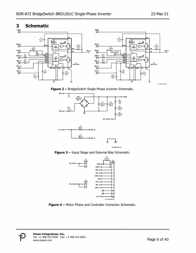
Schematic 3
Figure 2 – BridgeSwitch Single-Phase Inverter Schematic.
Figure 3 – Input Stage and External Bias Schematic.
Figure 4 – Motor Phase and Controller Connector Schematic.

23-Mar-21 RDR-872 BridgeSwitch BRD1261C Single-Phase Inverter
Page 7 of 40
Power Integrations Tel: +1 408 414 9200 Fax: +1 408 414 9201
www.power.com
Circuit Description 4
The schematic shows a single-phase inverter utilizing two BridgeSwitch devices. The circuit design drives a high-voltage, single-phase brushless DC (BLDC) motor with Hall sensors. BridgeSwitch integrates two 600 V, N-channel power FREDFETs with corresponding gate drives into a low-profile surface mount package. The BridgeSwitch power FREDFET features ultra-soft, fast recovery diode ideally suited for inverter drives. Both drivers are fully self-supplied thus eliminating the need for an auxiliary power supply.
In addition, BridgeSwitch incorporates internal fault protection and system level monitoring. Internal fault protection includes cycle-by-cycle current limit for both FREDFETs and a two-level thermal overload protection. On the other hand, system level monitoring includes high-voltage DC bus sensing with multi-level undervoltage thresholds and one overvoltage threshold. BridgeSwitch can also be configured using external sensors such as a thermistor for system temperature monitoring. A single-wire open-Drain bus communicates all detected faults or change of status to the system microcontroller.
Input Stage 4.1
The input stage consists of fuse F1, bridge diode BR1, inrush thermistor RT1, and input capacitor C1. Fuse F1 provides protection when there is an excessive input current. Bridge diode BR1 is used for input rectification and circuit protection in case the polarity of the input bus voltage is reversed. Thermistor RT1 is a negative temperature coefficient (NTC) device that initially presents a high resistance, which prevents large currents from flowing during turn-on therefore limiting inrush current. A bulk capacitor C1 is used for high input bus voltage.
Single-Phase BridgeSwitch Inverter 4.2
The two BridgeSwitch (BRD1261C) devices U1 and U2 form the single-phase inverter with the output of the inverter connected to the single-phase BLDC motor through connectors J1 and J2.
Self-Supply Operation 4.2.1
Capacitors C7 and C8 provide self-supply decoupling for the integrated low-side controller and gate driver. Internal high-voltage current sources charge C7 and C8. On the other hand, capacitors C3 and C4 provide self-supply decoupling for the integrated high-side controller and gate driver. Internal high-voltage current sources recharge C3 and C4 whenever the half-bridge voltage level of the respective device drops to the low-side source voltage level (i.e. the low-side FREDFET turns on).

RDR-872 BridgeSwitch BRD1261C Single-Phase Inverter 23-Mar-21
Page 8 of 40
Power Integrations, Inc. Tel: +1 408 414 9200 Fax: +1 408 414 9201 www.power.com
Control Inputs 4.2.2
Control input signals INL_U, /INH_U, and INL_V, /INH_V control the switching state of the integrated high-side and low-side power FREDFETs. The system microcontroller provides the required control input signals through pins 4, 5, 8, and 9 of the male header connector J3. The BridgeSwitch devices are compatible with 3.3 V and 5 V logic level control input signals. Series gate resistors R9, R10, R11, and R12 keep the signal integrity of these control signals.
Cycle-by-Cycle Current Limit 4.2.3
Resistor R7, R8, R14, and R16 set the cycle-by-cycle current limit level for the integrated low-side and high-side power FREDFETs. A selected value of 44.2 kΩ set the current limit to 100% of the default level. The BRD1261C device default current limit, ILIM(DEF), is
defined as 1.5 A typical with a di/dt value of 250 mA/µs.
Instantaneous Phase Current Information 4.2.4
The BridgeSwitch devices provide instantaneous phase current information of the low-side FREDFET Drain to Source current through the IPH pin output across resistors R13 and R15. The IPH pin output signals IPH_U and IPH_V of device U1 and U2 are available at pins 3 and 7 of the male header connector J3.
High-Voltage DC Bus Monitoring 4.2.5
BridgeSwitch device U2 monitors the DC input voltage through resistors R1, R2, and R3. The combined resistance of 7 MΩ sets four levels of undervoltage thresholds at 247 V, 212 V, 177 V, and 142 V. The overvoltage threshold is at 422 V. Capacitor C6 provides additional high frequency noise filtering at the SM pin of device U2.
External System Monitor 4.2.6
BridgeSwitch device U1 provides optional system monitor through its own SM pin. It can be configured as a system temperature sense with an external thermistor. Capacitor C5 provides additional high frequency noise filtering at the SM pin of device U1. The external system monitor input is available at pin 6 of the male header connector J3.
Status Communication Bus 4.2.7
The BridgeSwitch devices U1 and U2 report any detected internal and system status change through the communication bus (FAULT) connected to pin 2 of the male header connector J3. The two FAULT pins of the BridgeSwitch devices are tied together to form a single-wire bus. The status communication bus is an open-Drain architecture and the pull-up resistor R6 provides a pull-up supply to VDD at pin 1 of the male header connector J3.

23-Mar-21 RDR-872 BridgeSwitch BRD1261C Single-Phase Inverter
Page 9 of 40
Power Integrations Tel: +1 408 414 9200 Fax: +1 408 414 9201
www.power.com
Device ID 4.2.7.1
Each BridgeSwitch device assigns itself a unique device ID through the connection of pin 11 (ID pin). The pin connection can either be floating, connected to the SG pin or BPL pin. Device ID enables communication of faults from the actual devices to the system microcontroller. The ID pin of BridgeSwitch device U1 is configured to floating and
corresponds to a tID of 60 µs while the ID pin of BridgeSwitch device U2 is shorted to SG
and corresponds to a tID of 80 µs.
Interface Connector 4.2.8
The 12-position male header connector J3 interfaces with the system microcontroller for the control inputs, instantaneous phase current information, optional external system monitor and status communication bus.
External Supply 4.2.8.1
The 12-position male header connector J3 also provides an optional external supply input for the low-side bypass capacitors of the BridgeSwitch devices. It is available at pin 12 of the male header connector J3. A single input rail of 17 VDC is recommended to achieve low no-load input power consumption.

RDR-872 BridgeSwitch BRD1261C Single-Phase Inverter 23-Mar-21
Page 10 of 40
Power Integrations, Inc. Tel: +1 408 414 9200 Fax: +1 408 414 9201 www.power.com
Printed Circuit Board Layout 5
PCB thickness is 0.062 inches with a copper thickness of 2 ounces.
Figure 5 – Printed Circuit Layout, Top.
Figure 6 – Printed Circuit Layout, Bottom.

23-Mar-21 RDR-872 BridgeSwitch BRD1261C Single-Phase Inverter
Page 11 of 40
Power Integrations Tel: +1 408 414 9200 Fax: +1 408 414 9201
www.power.com
Bill of Materials 6Item Qty Ref Des Description Mfg Part Number Mfg
1 1 BR1 BRIDGE RECT, 1PHASE, 600 V, 2 A, 4-SIP, KBP KBP206G Diodes, Inc.
2 1 C1 100 µF, ±20%, 400 V, Aluminum Electrolytic Radial,
Can 12000 Hrs @ 105°C (12.5 x 52) 400BXW100MEFR12.5X50 Rubycon
3 1 C2 220 nF, 500 V, Ceramic, X7R, 1812 C1812C224KCRACTU Kemet
4 2 C3 C4 4.7 µF, ±10%, 25 V, Ceramic, X7R, 1206 GCM31CR71E475KA55L Murata
5 2 C5 C6 100 pF 200 V, Ceramic, NP0, 0603 C0603C101J2GAC7867 Kemet
6 2 C7 C8 1 µF, ±10%, 35V, Ceramic, X7R, 0603 C1608X7R1V105K080AE TDK
7 1 F1 2 A, 250 V, Slow, Long Time Lag, RST RST 2 Belfuse
8 2 J1 J2 CONN QC TAB 0.250 SOLDER 1287-ST KeyStone
9 1 J3 12 Position (1 x 12) Male header, 0.1 pitch, 0.126" (3.20 mm), Vertical, Au
PRPC012SFAN-RC Sullins Connector
10 1 R1 RES, 3 MΩ, 1%, 1/4 W, Thick Film, 1206 KTR18EZPF3004 Rohm
11 2 R2 R3 RES, 2.00 MΩ, 1%, 1/4 W, Thick Film, 1206 ERJ-8ENF2004V Panasonic
12 2 R4 R5 RES, 560 Ω, 5%, 1/10 W, Thick Film, 0603 ERJ-3GEYJ561V Panasonic
13 1 R6 RES, 4.7 kΩ, 5%, 1/10 W, Thick Film, 0603 ERJ-3GEYJ472V Panasonic
14 4 R7 R8
R14 R16 RES, 44.2 kΩ, 1%, 1/16 W, Thick Film, 0603 ERJ-3EKF4422V Panasonic
15 4 R9 R10 R11 R12
RES, 10 Ω, 5%, 1/10 W, Thick Film, 0603 ERJ-3GEYJ100V Panasonic
16 2 R13 R15 RES, 10.0 kΩ, 1%, 1/16 W, Thick Film, 0603 ERJ-3EKF1002V Panasonic
17 1 RT1 NTC Thermistor, 4 Ω, 5 A MF72-003D11 Cantherm
18 1 TP1 Test Point, WHT, THRU-HOLE MOUNT 5012 Keystone
19 1 TP2 Test Point, BLK, THRU-HOLE MOUNT 5011 Keystone
20 2 U1 U2 BridgeSwitch, Full Featured, Max. BLDC Motor Current 1.7 A (DC)
BRD1261C Power Integrations

RDR-872 BridgeSwitch BRD1261C Single-Phase Inverter 23-Mar-21
Page 12 of 40
Power Integrations, Inc. Tel: +1 408 414 9200 Fax: +1 408 414 9201 www.power.com
Performance Data 7
This section presents waveform plots and performance data of the BridgeSwitch single-phase inverter. An input voltage of 325 VDC was applied directly across the input capacitor C1 and the single-phase inverter is in self-supplied operation unless stated otherwise. Consequently, the fuse F1, inrush thermistor RT1 and bridge diode BR1 were disabled during operation and measurement. An external supply voltage of 17 VDC was applied to achieve externally-supplied low-side capacitor operation. Full-load operation describes the inverter operating 0.35 ARMS motor phase current, 6380 RPM, and 10 kHz PWM switching frequency using block commutation. All measurements were performed at 29 °C room ambient temperature.
Efficiency 7.1
The single-phase inverter efficiency was measured using DC input power at 325 VDC applied directly across input capacitor C1 and respective inverter RMS output power in self-supplied and externally-supplied operation.
Figure 7 – BRD1261C Single-Phase Inverter Efficiency.
92
93
94
95
96
97
98
99
100
10 20 30 40 50 60 70 80
Invert
er
Eff
icie
ncy (
%)
Inverter Output Power (W)
Self-Supplied EfficiencyExternally-Supplied Efficiency

23-Mar-21 RDR-872 BridgeSwitch BRD1261C Single-Phase Inverter
Page 13 of 40
Power Integrations Tel: +1 408 414 9200 Fax: +1 408 414 9201
www.power.com
DC Input
Voltage (V)
Speed
(RPM)
DC Input
Power (W)
Motor RMS
Phase Voltage
(V)
Motor RMS
Phase Current
(mA)
Inverter Output
Power
(W)
Inverter
Efficiency (%)
325.35 6380 72.20 303.35 354.29 70.56 97.73
325.37 5820 54.07 269.43 291.60 52.70 97.47
325.36 5030 36.44 230.73 245.74 35.27 96.79
325.38 3870 18.70 181.83 206.37 17.68 94.54
Table 2 – Single-phase inverter efficiency data in self-supplied operation
DC Input Voltage
(V)
Speed (RPM)
DC Input Power
(W)
Motor
RMS Phase
Voltage (V)
Motor
RMS Phase
Current (mA)
Inverter
Output Power
(W)
Inverter Efficiency
(%)
325.36 6380 71.65 302.08 352.12 70.24 98.03
325.39 5820 54.01 269.46 292.50 52.85 97.85
325.38 5030 36.20 230.17 246.71 35.25 97.38
325.40 3870 18.61 182.35 206.78 17.83 95.81
Table 3 – Single-phase inverter efficiency data in externally-supplied operation.

RDR-872 BridgeSwitch BRD1261C Single-Phase Inverter 23-Mar-21
Page 14 of 40
Power Integrations, Inc. Tel: +1 408 414 9200 Fax: +1 408 414 9201 www.power.com
No-Load Input Power 7.2
The single-phase inverter no-load input power was measured across different DC input voltages (255, 285, 325, and 375 VDC) applied directly across the input capacitor C1 corresponding to the following AC input voltages (180, 200, 230, and 265 VAC) in self-supplied and externally-supplied operation.
Figure 8 – No-Load Input Power.
0
50
100
150
200
250
300
350
400
240 255 270 285 300 315 330 345 360 375 390
No
-Lo
ad
In
pu
t P
ow
er
(mW
)
Input Voltage (VDC)
Self-Supplied No-LoadExternally-Supplied No-Load

23-Mar-21 RDR-872 BridgeSwitch BRD1261C Single-Phase Inverter
Page 15 of 40
Power Integrations Tel: +1 408 414 9200 Fax: +1 408 414 9201
www.power.com
Thermal Performance 7.3
The single-phase inverter thermal performance was measured using the DC input power at 325 VDC applied directly across the input capacitor C1 during half-load (35 W) and full-load (70 W) output power in self-supplied and externally-supplied operation at 29 °C room ambient temperature. Single-phase inverter thermal scan in self-supplied operation.
Figure 9 – 35 W Inverter Output Power.
Bx1: Half-Bridge U: 47.9 ºC.
Bx2: Half-Bridge V: 47.7 ºC.
Figure 10 – 70 W Inverter Output Power.
Bx1: Half-Bridge U: 53.6 ºC.
Bx2: Half-Bridge V: 55.0 ºC.
Single-phase inverter thermal scan in externally-supplied operation.
Figure 11 – 35 W Inverter Output Power.
Bx1: Half-Bridge U: 44.7 ºC. Bx2: Half-Bridge V: 45.8 ºC.
Figure 12 – 70 W Inverter Output Power.
Bx1: Half-Bridge U: 51.5 ºC. Bx2: Half-Bridge V: 52.9 ºC.

RDR-872 BridgeSwitch BRD1261C Single-Phase Inverter 23-Mar-21
Page 16 of 40
Power Integrations, Inc. Tel: +1 408 414 9200 Fax: +1 408 414 9201 www.power.com
The maximum device case temperature rise above the room ambient temperature in self-supplied and externally-supplied operation is illustrated below.
Figure 13 – Device Case Temperature Rise.
26.0
18.9
23.9
16.8
12
14
16
18
20
22
24
26
28
30
230 245 260 275 290 305 320 335 350 365
Ca
se T
em
pera
ture
Ris
e (
°C
)
Inverter Phase Current (mArms)
Self-Supplied BRD1261CExternally-Supplied BRD1261C

23-Mar-21 RDR-872 BridgeSwitch BRD1261C Single-Phase Inverter
Page 17 of 40
Power Integrations Tel: +1 408 414 9200 Fax: +1 408 414 9201
www.power.com
Start-Up Operation 7.4
Figure 14 – BPH and BPL-pin Voltages at Start-Up.
CH1: IPHASE, 500 mA / div.
CH2: VBPH, 10 V / div.
CH3: VBPL, 10 V / div. CH4: VINL, 5 V / div.
Time: 1 s / div.
Figure 15 – Motor and PWM Waveforms during Start-Up.
CH1: IPHASE, 500 mA / div.
CH2: VHB, 200 V / div. CH3: V/INH, 5 V / div.
CH4: VINL, 5 V / div.
Time: 1 s / div. Zoom: 50 ms / div.

RDR-872 BridgeSwitch BRD1261C Single-Phase Inverter 23-Mar-21
Page 18 of 40
Power Integrations, Inc. Tel: +1 408 414 9200 Fax: +1 408 414 9201 www.power.com
Steady-State Operation 7.5
Phase Current During Steady-State 7.5.1
Figure 16 – Phase Current at 35 W Inverter Output Power.
CH1: IPHASE, 300 mA / div. IPHASE,RMS: 247.4 mA. CH3: V/INH, 5 V / div.
CH4: VINL, 5 V / div.
Time: 10 ms / div. Zoom: 5 ms / div.
Figure 17 – Phase Current at 70 W Inverter Output Power.
CH1: IPHASE, 300 mA / div. IPHASE,RMS: 354.5 mA. CH3: V/INH, 5 V / div.
CH4: VINL, 5 V / div. Time: 10 ms / div.
Zoom: 5 ms / div.

23-Mar-21 RDR-872 BridgeSwitch BRD1261C Single-Phase Inverter
Page 19 of 40
Power Integrations Tel: +1 408 414 9200 Fax: +1 408 414 9201
www.power.com
Half-Bridge Voltages During Steady-State 7.5.2
Figure 18 – Half-Bridge Voltages at 35 W Inverter Output Power.
CH1: VHB(U), 100 V / div. VHB(U),MAX: 340.1 V. CH2: VHB(V), 100 V / div. VHB(V),MAX: 340.2 V.
Time: 2 ms / div.
Figure 19 – Half-Bridge Voltages at 70 W Inverter Output Power.
CH1: VHB(U), 100 V / div. VHB(U),MAX: 345.3 V.
CH2: VHB(V), 100 V / div. VHB(V),MAX: 345.0 V.
Time: 2 ms / div.

RDR-872 BridgeSwitch BRD1261C Single-Phase Inverter 23-Mar-21
Page 20 of 40
Power Integrations, Inc. Tel: +1 408 414 9200 Fax: +1 408 414 9201 www.power.com
/INH and INL Input Signals During Steady-State 7.5.3
Figure 20 – /INH and INL Signals at 35 W Inverter Output Power.
CH1: IPHASE, 500 mA / div. CH2: VHB, 200 V / div.
CH3: V/INH, 5 V / div.
CH4: VINL, 5 V / div. Time: 20 ms / div.
Zoom: 200 µs / div. fPWM: 10.05 kHz.
Figure 21 – /INH and INL Signals at 70 W Inverter Output Power.
CH1: IPHASE, 500 mA / div. CH2: VHB, 200 V / div.
CH3: V/INH, 5 V / div. CH4: VINL, 5 V / div.
Time: 20 ms / div.
Zoom: 200 µs / div. fPWM: 10.05 kHz.

23-Mar-21 RDR-872 BridgeSwitch BRD1261C Single-Phase Inverter
Page 21 of 40
Power Integrations Tel: +1 408 414 9200 Fax: +1 408 414 9201
www.power.com
Bypass Pin Voltages During Steady-State 7.5.4
Figure 22 – BPH and BPL-pin Voltages at 35 W Inverter Output
Power. CH1: IPHASE, 500 mA / div.
CH2: VBPH, 10 V / div.
CH3: VBPL, 10 V / div. CH4: VINL, 5 V / div.
Time: 20 ms / div. Zoom: 5 ms / div.
Figure 23 – BPH and BPL-pin Voltages at 70 W Inverter Output
Power. CH1: IPHASE, 500 mA / div.
CH2: VBPH, 10 V / div. CH3: VBPL, 10 V / div.
CH4: VINL, 5 V / div.
Time: 20 ms / div. Zoom: 5 ms / div.

RDR-872 BridgeSwitch BRD1261C Single-Phase Inverter 23-Mar-21
Page 22 of 40
Power Integrations, Inc. Tel: +1 408 414 9200 Fax: +1 408 414 9201 www.power.com
Phase Current Information Output (IPH) 7.5.5
Figure 24 – IPH Output Signal at 35 W Inverter Output Power.
CH1: IPHASE, 500 mA / div. CH2: VHB, 200 V / div.
CH4: VIPH, 1 V / div.
Time: 10 ms / div. Zoom: 2.5 ms / div.
Figure 25 – IPH Output Signal at 70 W Inverter Output Power.
CH1: IPHASE, 500 mA / div. CH2: VHB, 200 V / div.
CH4: VIPH, 1 V / div. Time: 10 ms / div.
Zoom: 2.5 ms / div.

23-Mar-21 RDR-872 BridgeSwitch BRD1261C Single-Phase Inverter
Page 23 of 40
Power Integrations Tel: +1 408 414 9200 Fax: +1 408 414 9201
www.power.com
FREDFET Drain Voltage Slew Rate at Full Load 7.5.6
Figure 26 – Drain Voltage (Turn-Off) 70 W Inverter Output Power.
CH1: IPHASE, 500 mA / div. CH2: VHB, 50 V / div.
CH3: V/INH, 5 V / div.
Time: 2 ms / div. Zoom: 100 ns / div. Turn-Off Slew Rate: 2.21 V / ns.
Figure 27 – Drain Voltage (Turn-On) 70 W Inverter Output Power.
CH1: IPHASE, 500 mA / div. CH2: VHB, 50 V / div.
CH3: V/INH, 5 V / div. Time: 2 ms / div.
Zoom: 100 ns / div. Turn-On Slew Rate: 2.12 V / ns.

RDR-872 BridgeSwitch BRD1261C Single-Phase Inverter 23-Mar-21
Page 24 of 40
Power Integrations, Inc. Tel: +1 408 414 9200 Fax: +1 408 414 9201 www.power.com
Device and System Level Protection and Monitoring 8
Integrated Cycle-by-Cycle Current Limit 8.1
Figures 28 and 29 illustrate the integrated cycle-by-cycle current limit of the BridgeSwitch devices. Resistor R14 and R16 were replaced by 133 kΩ (yielding a typical current limit of 0.630 A) to demonstrate the current limit.
Figure 28 – CH1: IPHASE, 500 mA / div. Ipk: 625 mA.
CH2: VHB, 100 V / div.
CH3: VFAULT, 5 V / div.
Time: 10 ms / div.
Zoom: 100 µs / div. Low-Side FET Overcurrent U1.
Figure 29 – CH1: IPHASE, 500 mA / div. Ipk: 592 mA.
CH2: VHB, 100 V / div.
CH3: VFAULT, 5 V / div. Time: 10 ms / div.
Zoom: 100 µs / div. Low-Side FET Overcurrent U2.

23-Mar-21 RDR-872 BridgeSwitch BRD1261C Single-Phase Inverter
Page 25 of 40
Power Integrations Tel: +1 408 414 9200 Fax: +1 408 414 9201
www.power.com
Two-level Device Over-Temperature Protection 8.2
Figures 30 and 31 illustrate two-level device over-temperature warning and protection of the BridgeSwitch devices. An external heat source is applied to device U1 during operation.
Figure 30 – CH1: IPHASE, 500 mA / div.
CH3: V/INH, 5 V / div. CH4: VINL, 5 V / div.
Time: 20 ms / div.
Zoom: 100 µs / div. Over-Temperature Warning U1.
Figure 31 – CH1: IPHASE, 500 mA / div.
CH3: V/INH, 5 V / div.
CH4: VINL, 5 V / div. Time: 20 ms / div.
Zoom: 100 µs / div. Over-Temperature Protection U1.

RDR-872 BridgeSwitch BRD1261C Single-Phase Inverter 23-Mar-21
Page 26 of 40
Power Integrations, Inc. Tel: +1 408 414 9200 Fax: +1 408 414 9201 www.power.com
High-Voltage DC Bus Monitoring 8.3
Undervoltage Thresholds 8.3.1
Figures 32 to 35 illustrate the four levels of undervoltage thresholds. BridgeSwitch device U2 senses the reduction in input voltage and provides the status report.
Figure 32 – 325 to 240 VDC, Slew Rate: 5 V / ms.
CH1: IPHASE, 1 A / div.
CH2: VDC INPUT, 50 V / div. CH3: VFAULT, 5 V / div.
Time: 20 ms / div.
Zoom: 100 µs / div. Undervoltage IUV100 U2.
Figure 33 – 240 to 200 VDC, Slew Rate: 5 V / ms.
CH1: IPHASE, 1 A / div.
CH2: VDC INPUT, 50 V / div. CH3: VFAULT, 5 V / div.
Time: 20 ms / div.
Zoom: 100 µs / div. Undervoltage IUV85 U2.

23-Mar-21 RDR-872 BridgeSwitch BRD1261C Single-Phase Inverter
Page 27 of 40
Power Integrations Tel: +1 408 414 9200 Fax: +1 408 414 9201
www.power.com
Figure 34 – 200 to 160 VDC, Slew Rate: 5 V / ms.
CH1: IPHASE, 1 A / div. CH2: VDC INPUT, 50 V / div.
CH3: VFAULT, 5 V / div.
Time: 20 ms / div.
Zoom: 100 µs / div. Undervoltage IUV70 U2.
Figure 35 – 160 to 130 VDC, Slew Rate: 5 V / ms.
CH1: IPHASE, 1 A / div.
CH2: VDC INPUT, 50 V / div. CH3: VFAULT, 5 V / div.
Time: 20 ms / div.
Zoom: 100 µs / div. Undervoltage IUV55 U2.

RDR-872 BridgeSwitch BRD1261C Single-Phase Inverter 23-Mar-21
Page 28 of 40
Power Integrations, Inc. Tel: +1 408 414 9200 Fax: +1 408 414 9201 www.power.com
Overvoltage Threshold 8.3.2
Figures 36 and 37 illustrate the overvoltage threshold and hysteresis. BridgeSwitch device U2 senses the increase in input voltage and provides the status report.
Figure 36 – 325 to 425 VDC, Slew Rate: 5 V / ms.
CH1: IPHASE, 1 A / div. CH2: VDC INPUT, 50 V / div.
CH3: VFAULT, 5 V / div.
Time: 20 ms / div.
Zoom: 100 µs / div. Overvoltage IOV U2.
Figure 37 – 425 to 325 VDC, Slew Rate: 5 V / ms.
CH1: IPHASE, 1 A / div.
CH2: VDC INPUT, 50 V / div. CH3: VFAULT, 5 V / div.
Time: 20 ms / div.
Zoom: 100 µs / div. Device Ready (no faults) U2.

23-Mar-21 RDR-872 BridgeSwitch BRD1261C Single-Phase Inverter
Page 29 of 40
Power Integrations Tel: +1 408 414 9200 Fax: +1 408 414 9201
www.power.com
Abnormal Motor Operation 9
This section provides the results of the abnormal operation tests performed on the RD-872 inverter board. The abnormal operation test complies with the abnormal test for appliances with motors as described in IEC 60335-1 standard (safety of household and similar electrical appliances). The abnormal operation tests cover the following:
1. Motor stall conditions 2. Motor operation during overload 3. Motor winding disconnect during operation
The test results demonstrate the integrated protection mechanism feature of BridgeSwitch under such abnormal operations without microcontroller intervention for protection.
Motor Stall Conditions 9.1
Figures 38 and 39 illustrate the motor stall during start-up and running operation. Motor is non-operational during testing with no damage to device or motor during or after testing.
Figure 38 – Motor Stalled During Start-Up Condition.
CH1: IPHASE, 500 mA / div. CH3: V/INH, 5 V / div.
CH4: VINL, 5 V / div.
Time: 20 ms / div.
Zoom: 100 µs / div. Low-Side FET Overcurrent U2.

RDR-872 BridgeSwitch BRD1261C Single-Phase Inverter 23-Mar-21
Page 30 of 40
Power Integrations, Inc. Tel: +1 408 414 9200 Fax: +1 408 414 9201 www.power.com
Figure 39 – Motor Stalled During Running Condition.
CH1: IPHASE, 500 mA / div. CH3: V/INH, 5 V / div.
CH4: VINL, 5 V / div.
Time: 20 ms / div.
Zoom: 100 µs / div. Low-Side FET Overcurrent U2.

23-Mar-21 RDR-872 BridgeSwitch BRD1261C Single-Phase Inverter
Page 31 of 40
Power Integrations Tel: +1 408 414 9200 Fax: +1 408 414 9201
www.power.com
Motor Overload During Operation 9.2
Figures 40 illustrates the motor overload during operation. Motor will stall upon overload during testing with no damage to device or motor during or after testing.
Figure 40 – CH1: IPHASE, 500 mA / div.
CH3: V/INH, 5 V / div. CH4: VINL, 5 V / div.
Time: 20 ms / div.
Zoom: 100 µs / div. Low-Side FET Overcurrent U1.

RDR-872 BridgeSwitch BRD1261C Single-Phase Inverter 23-Mar-21
Page 32 of 40
Power Integrations, Inc. Tel: +1 408 414 9200 Fax: +1 408 414 9201 www.power.com
Motor Winding Disconnect During Operation 9.3
Figures 41 illustrates the motor winding disconnect during operation. Winding disconnection results to a signal distortion in the FAULT bus. Overcurrent faults occur after the high-side driver not ready fault and the motor will stall during testing with no damage to device or motor during or after testing.
Figure 41 – CH1: IPHASE, 1 A / div.
CH2: VBPH, 10 V / div.
CH3: VFAULT, 5 V / div. CH4: VINL, 5 V / div.
Time: 10 ms / div.
Zoom: 100 µs / div. High-Side Driver Not Ready U1.

23-Mar-21 RDR-872 BridgeSwitch BRD1261C Single-Phase Inverter
Page 33 of 40
Power Integrations Tel: +1 408 414 9200 Fax: +1 408 414 9201
www.power.com
Appendix 10
Inverter Circuit Board Manual 10.1
Figure 42 illustrates the locations and functions of all connectors for the single-phase inverter board.
Figure 42 – Single-Phase Inverter Board Connectors.
The AC input required to operate the inverter board is connected through test points, TP1 and TP2.
The single motor winding is connected through quick-connect solder tabs, J1 and J2. The half-bridge output of device U1 is connected to J1 while the half-bridge output of device U2 is connected to J2.
The inverter control and external bias are connected through the male header connector, J3. Figure 43 illustrates the physical specifications of the male header connector J3. The functions tied to this connector include the pull-up supply for the communication bus, control input signals, optional system monitor input, phase current information output signals and the external supply for low-side capacitor bias. Table 4 illustrates the pin assignments and detailed information for the male header connector J3.

RDR-872 BridgeSwitch BRD1261C Single-Phase Inverter 23-Mar-21
Page 34 of 40
Power Integrations, Inc. Tel: +1 408 414 9200 Fax: +1 408 414 9201 www.power.com
Figure 43 – Inverter Control and External Bias Connector Specifications.
Pin
No
Signal Type Details
1 VDD Input Pull-up supply for communication for status update communication
bus, 3.3 V and 5 V compatible
2 FAULT Input/Output Single-wire, bidirectional communication bus (open-Drain)
3 IPH_U Output Instantaneous phase current information output of device U1
4 INL_U Input Gate-drive signal for low-side FREDFET of device U1, active high, 3.3
V and 5 V compatible
5 /INH_U Input Gate-drive signal for high-side FREDFET of device U1, active low, 3.3
V and 5 V compatible
6 SM Input System monitor input (e.g. high-voltage DC bus monitoring, system
level temperature monitoring)
7 IPH_V Output Instantaneous phase current information output of device U2
8 INL_V Input Gate-drive signal for low-side FREDFET of device U2, active high, 3.3
V and 5 V compatible
9 /INH_V Input Gate-drive signal for high-side FREDFET of device U2, active low, 3.3
V and 5 V compatible
10 GND n/a Ground reference for connector input and output signals, inverter and
system MCU
11 GND n/a Ground reference for connector input and output signals, inverter and
system MCU
12 +17V Input External supply for low-side bypass capacitor bias
Table 4 – Inverter Board Interface Connector Pin Assignments.

23-Mar-21 RDR-872 BridgeSwitch BRD1261C Single-Phase Inverter
Page 35 of 40
Power Integrations Tel: +1 408 414 9200 Fax: +1 408 414 9201
www.power.com
Status Word Encoding 10.2
BridgeSwitch uses a 7-bit word followed by a parity bit to report a status update. Table 5 summarizes how various conditions are encoded. The 7-bit word consists of five blocks with status changes grouped together that cannot occur at the same time. This enables simultaneous reporting of multiple fault conditions to the system MCU.
The status register entry in the bottom row (7-bit word “000 00 0 0”) encodes Device Ready status and is used to communicate a successful power-up sequence. The device also sends it to acknowledge a status request sent by the system MCU in case no fault condition is present at the time. The parity bit is generated using odd parity.
FAULT Bit 0 Bit 1 Bit 2 Bit 3 Bit 4 Bit 5 Bit 6
HV bus OV 0 0 1
HV bus UV 100% 0 1 0
HV bus UV 85% 0 1 1
HV bus UV 70% 1 0 0
HV bus UV 55% 1 0 1
System thermal fault 1 1 0
LS Driver not ready[1] 1 1 1
LS FET thermal warning 0 1
LS FET thermal shutdown 1 0
HS Driver not ready[2] 1 1
LS FET over-current 1
HS FET over-current 1
Device Ready (no faults) 0 0 0 0 0 0 0
Notes: 1. Includes XL-pin open/short circuit fault, IPH pin to XL pin short circuit, and trim bit corruption 2. Includes HS-to-LS communication loss, VBPH or internal 5 V rail out of range, and XH pin open/short-
circuit fault
Table 5 – Status Word Encoding.

RDR-872 BridgeSwitch BRD1261C Single-Phase Inverter 23-Mar-21
Page 36 of 40
Power Integrations, Inc. Tel: +1 408 414 9200 Fax: +1 408 414 9201 www.power.com
Test Bench Set-up 10.3
Figure 44 illustrates the test bench used to obtain the performance data of the single-phase inverter in this report. Table 6 details the specific equipment used in this report.
Figure 44 – Populated Circuit Board Photograph.
Test Bench Item Model/Specification
HV DC Source Keysight 6812B
Oscilloscope Tektronix MSO58
LV DC Source Topward 6303A
Input & Output Power Meter Yokogawa W310E
Single-Phase Motor NRG118/0800-3612 EC
Centrifugal Fan
RD-872 Single-Phase Inverter
Controller Board CY8CKIT-042 Pioneer Kit
Table 6 – Test Bench Details.

23-Mar-21 RDR-872 BridgeSwitch BRD1261C Single-Phase Inverter
Page 37 of 40
Power Integrations Tel: +1 408 414 9200 Fax: +1 408 414 9201
www.power.com
Inverter Output Power Measurement 10.4
Figure 45 illustrates the wattmeter configuration used to obtain the inverter input and output power in this report.
IO
VO
II
VI
+
-
DC Input
Figure 45 – Inverter Input and Output Power Measurement Diagram.

RDR-872 BridgeSwitch BRD1261C Single-Phase Inverter 23-Mar-21
Page 38 of 40
Power Integrations, Inc. Tel: +1 408 414 9200 Fax: +1 408 414 9201 www.power.com
Current Capability and Ambient Temperature 10.5
Figure 46 illustrates the RMS current capability of the RD-872 single-phase inverter board. It shows two curves with two BRD1261C devices operating in self-supplied or externally-supplied operation at the respective BPL pins. Each curve details the available continuous RMS current at different board ambient temperatures with a package temperature of 100 °C.
Figure 46 – Device Case Temperature Rise.
140
170
200
230
260
290
320
350
380
70 72 74 76 78 80 82 84 86
Invert
er
Ph
ase C
urr
en
t (m
Arm
s)
Ambient Temperature (°C)
Self-Supplied BRD1261CExternally-Supplied BRD1261C

23-Mar-21 RDR-872 BridgeSwitch BRD1261C Single-Phase Inverter
Page 39 of 40
Power Integrations Tel: +1 408 414 9200 Fax: +1 408 414 9201
www.power.com
Revision History 11
Date Author Revision Description & Changes Reviewed
23-Mar-21 NAM 1.1 Initial Release Apps & Mktg

RDR-872 BridgeSwitch BRD1261C Single-Phase Inverter 23-Mar-21
Page 40 of 40
Power Integrations, Inc. Tel: +1 408 414 9200 Fax: +1 408 414 9201 www.power.com
For the latest updates, visit our website: www.power.com Reference Designs are technical proposals concerning how to use Power Integrations’ gate drivers in particular applications and/or with certain power modules. These proposals are “as is” and are not subject to any qualification process. The suitability, implementation and qualification are the sole responsibility of the end user. The statements, technical information and recommendations contained herein are believed to be accurate as of the date hereof. All parameters, numbers, values and other technical data included in the technical information were calculated and determined to our best knowledge in accordance with the relevant technical norms (if any). They may base on assumptions or operational conditions that do not necessarily apply in general. We exclude any representation or warranty, express or implied, in relation to the accuracy or completeness of the statements, technical information and recommendations contained herein. No responsibility is accepted for the accuracy or sufficiency of any of the statements, technical information, recommendations or opinions communicated and any liability for any direct, indirect or consequential loss or damage suffered by any person arising therefrom is expressly disclaimed.
Power Integrations reserves the right to make changes to its products at any time to improve reliability or manufacturability. Power Integrations does not assume any liability arising from the use of any device or circuit described herein. POWER INTEGRATIONS MAKES NO WARRANTY HEREIN AND SPECIFICALLY DISCLAIMS ALL WARRANTIES INCLUDING, WITHOUT LIMITATION, THE IMPLIED WARRANTIES OF MERCHANTABILITY, FITNESS FOR A PARTICULAR PURPOSE, AND NON-INFRINGEMENT OF THIRD PARTY RIGHTS.
Patent Information The products and applications illustrated herein (including transformer construction and circuits’ external to the products) may be covered by one or more U.S. and foreign patents, or potentially by pending U.S. and foreign patent applications assigned to Power Integrations. A complete list of Power Integrations’ patents may be found at www.power.com. Power Integrations grants its customers a license under certain patent rights as set forth at http://www.power.com/ip.htm.
Power Integrations, the Power Integrations logo, CAPZero, ChiPhy, CHY, DPA-Switch, EcoSmart, E-Shield, eSIP, eSOP, HiperPLC, HiperPFS, HiperTFS, InnoSwitch, Innovation in Power Conversion, InSOP, LinkSwitch, LinkZero, LYTSwitch, SENZero, TinySwitch, TOPSwitch, PI, PI Expert, SCALE, SCALE-1, SCALE-2, SCALE-3 and SCALE-iDriver, are trademarks of Power Integrations, Inc. Other trademarks are property of their respective companies. ©2019, Power Integrations, Inc.
Power Integrations Worldwide Sales Support Locations WORLD HEADQUARTERS 5245 Hellyer Avenue San Jose, CA 95138, USA. Main: +1-408-414-9200
Customer Service:
Worldwide: +1-65-635-64480
Americas: +1-408-414-9621 e-mail: [email protected] CHINA (SHANGHAI)
Rm 2410, Charity Plaza, No. 88,
North Caoxi Road,
Shanghai, PRC 200030
Phone: +86-21-6354-6323 e-mail: [email protected] CHINA (SHENZHEN)
17/F, Hivac Building, No. 2, Keji
Nan 8th Road, Nanshan District,
Shenzhen, China, 518057
Phone: +86-755-8672-8689 e-mail: [email protected]
GERMANY (AC-DC/LED Sales)
Einsteinring 24
85609 Dornach/Aschheim
Germany
Tel: +49-89-5527-39100
e-mail: [email protected]
GERMANY (Gate Driver Sales) HellwegForum 1 59469 Ense Germany Tel: +49-2938-64-39990 e-mail: igbt-driver.sales@ power.com INDIA #1, 14th Main Road Vasanthanagar Bangalore-560052 India Phone: +91-80-4113-8020 e-mail: [email protected]
ITALY Via Milanese 20, 3rd. Fl. 20099 Sesto San Giovanni (MI) Italy Phone: +39-024-550-8701 e-mail: [email protected] JAPAN Yusen Shin-Yokohama 1-chome Bldg. 1-7-9, Shin-Yokohama, Kohoku-ku Yokohama-shi, Kanagawa 222-0033 Japan Phone: +81-45-471-1021 e-mail: [email protected] KOREA RM 602, 6FL Korea City Air Terminal B/D, 159-6 Samsung-Dong, Kangnam-Gu, Seoul, 135-728 Korea Phone: +82-2-2016-6610 e-mail: [email protected]
SINGAPORE 51 Newton Road, #19-01/05 Goldhill Plaza Singapore, 308900 Phone: +65-6358-2160 e-mail: [email protected]
TAIWAN 5F, No. 318, Nei Hu Rd., Sec. 1 Nei Hu District Taipei 11493, Taiwan R.O.C. Phone: +886-2-2659-4570 e-mail: [email protected] UK
Building 5, Suite 21
The Westbrook Centre
Milton Road
Cambridge
CB4 1YG
Phone: +44 (0) 7823-557484 e-mail: [email protected]