reference manual - gongkong
TRANSCRIPT

Cat. No. W342-E1-05 SYSMAC CS/CJ SeriesCS1G/H-CPU��H
REFERENCE MANUAL
CS1G/H-CPU��-ECS1W-SCB21/41CS1W-SCU21CJ1G/H-CPU��HCJ1G-CPU��CJ1W-SCU41Communications Commands

������������������ �������@@��� �������@@���� ������ �� �� ������ �� �������@@��� �����@@�� ������ ����������������������� !��������"������������ �����

iv

�������OMRON products are manufactured for use according to proper procedures by a qualified operatorand only for the purposes described in this manual.
The following conventions are used to indicate and classify precautions in this manual. Always heedthe information provided with them. Failure to heed precautions can result in injury to people or dam-age to property.
!DANGER Indicates an imminently hazardous situation which, if not avoided, will result in death orserious injury.
!WARNING Indicates a potentially hazardous situation which, if not avoided, could result in death orserious injury.
!Caution Indicates a potentially hazardous situation which, if not avoided, may result in minor ormoderate injury, or property damage.
����� ��������� �����All OMRON products are capitalized in this manual. The word “Unit” is also capitalized when it refers toan OMRON product, regardless of whether or not it appears in the proper name of the product.
The abbreviation “Ch,” which appears in some displays and on some OMRON products, often means“word” and is abbreviated “Wd” in documentation in this sense.
The abbreviation “PC” means Programmable Controller and is not used as an abbreviation for anythingelse.
�����������The following headings appear in the left column of the manual to help you locate different types ofinformation.
Note Indicates information of particular interest for efficient and convenient opera-tion of the product.
1,2,3... �� �������� ���������������������������������������������� �������
� OMRON, 1999All rights reserved. No part of this publication may be reproduced, stored in a retrieval system, or transmitted, in any form, orby any means, mechanical, electronic, photocopying, recording, or otherwise, without the prior written permission ofOMRON.
No patent liability is assumed with respect to the use of the information contained herein. Moreover, because OMRON is con-stantly striving to improve its high-quality products, the information contained in this manual is subject to change withoutnotice. Every precaution has been taken in the preparation of this manual. Nevertheless, OMRON assumes no responsibilityfor errors or omissions. Neither is any liability assumed for damages resulting from the use of the information contained inthis publication.
v

vi

TABLE OF CONTENTS
PRECAUTIONS . . . . . . . . . . . . . . . . . . . . . . . . . . . . . . . . . . . xi1 Intended Audience . . . . . . . . . . . . . . . . . . . . . . . . . . . . . . . . . . . . . . . . . . . . . . . . . . . . . . . . xii
2 General Precautions . . . . . . . . . . . . . . . . . . . . . . . . . . . . . . . . . . . . . . . . . . . . . . . . . . . . . . . xii
3 Safety Precautions. . . . . . . . . . . . . . . . . . . . . . . . . . . . . . . . . . . . . . . . . . . . . . . . . . . . . . . . . xii
4 Operating Environment Precautions . . . . . . . . . . . . . . . . . . . . . . . . . . . . . . . . . . . . . . . . . . . xiii
5 Application Precautions . . . . . . . . . . . . . . . . . . . . . . . . . . . . . . . . . . . . . . . . . . . . . . . . . . . . xiv
SECTION 1Introduction . . . . . . . . . . . . . . . . . . . . . . . . . . . . . . . . . . . . . . 1
1-1 Overview of Communications Commands . . . . . . . . . . . . . . . . . . . . . . . . . . . . . . . . . . . . . . 2
1-2 C-mode Commands. . . . . . . . . . . . . . . . . . . . . . . . . . . . . . . . . . . . . . . . . . . . . . . . . . . . . . . . 2
1-3 FINS Commands. . . . . . . . . . . . . . . . . . . . . . . . . . . . . . . . . . . . . . . . . . . . . . . . . . . . . . . . . . 4
SECTION 2Overview of C-mode Commands . . . . . . . . . . . . . . . . . . . . . 7
2-1 C-mode Commands. . . . . . . . . . . . . . . . . . . . . . . . . . . . . . . . . . . . . . . . . . . . . . . . . . . . . . . . 8
2-2 Command/Response Formats . . . . . . . . . . . . . . . . . . . . . . . . . . . . . . . . . . . . . . . . . . . . . . . . 9
2-3 Application Example. . . . . . . . . . . . . . . . . . . . . . . . . . . . . . . . . . . . . . . . . . . . . . . . . . . . . . . 14
2-4 Precautions in Using Programs from Previous PC Models . . . . . . . . . . . . . . . . . . . . . . . . . 15
SECTION 3Overview of FINS Commands. . . . . . . . . . . . . . . . . . . . . . . . 23
3-1 FINS Commands. . . . . . . . . . . . . . . . . . . . . . . . . . . . . . . . . . . . . . . . . . . . . . . . . . . . . . . . . . 24
3-2 Using FINS Commands . . . . . . . . . . . . . . . . . . . . . . . . . . . . . . . . . . . . . . . . . . . . . . . . . . . . 26
3-3 FINS Command and Response Frames . . . . . . . . . . . . . . . . . . . . . . . . . . . . . . . . . . . . . . . . 27
3-4 Settings for Sending FINS Commands . . . . . . . . . . . . . . . . . . . . . . . . . . . . . . . . . . . . . . . . . 29
3-5 FINS Commands with Host Link Protocol . . . . . . . . . . . . . . . . . . . . . . . . . . . . . . . . . . . . . . 37
SECTION 4C-mode Commands . . . . . . . . . . . . . . . . . . . . . . . . . . . . . . . . 59
4-1 C-mode Command List . . . . . . . . . . . . . . . . . . . . . . . . . . . . . . . . . . . . . . . . . . . . . . . . . . . . . 60
4-2 End Codes . . . . . . . . . . . . . . . . . . . . . . . . . . . . . . . . . . . . . . . . . . . . . . . . . . . . . . . . . . . . . . . 63
4-3 C-mode Command Details . . . . . . . . . . . . . . . . . . . . . . . . . . . . . . . . . . . . . . . . . . . . . . . . . . 65
SECTION 5FINS Commands . . . . . . . . . . . . . . . . . . . . . . . . . . . . . . . . . . 109
5-1 Command Lists . . . . . . . . . . . . . . . . . . . . . . . . . . . . . . . . . . . . . . . . . . . . . . . . . . . . . . . . . . . 110
5-2 Designating Command Parameters . . . . . . . . . . . . . . . . . . . . . . . . . . . . . . . . . . . . . . . . . . . . 119
5-3 FINS Commands. . . . . . . . . . . . . . . . . . . . . . . . . . . . . . . . . . . . . . . . . . . . . . . . . . . . . . . . . . 126
Index . . . . . . . . . . . . . . . . . . . . . . . . . . . . . . . . . . . . . . . . . . . . 181
Revision History . . . . . . . . . . . . . . . . . . . . . . . . . . . . . . . . . . . 185
vii

TABLE OF CONTENTS
viii
�����������������
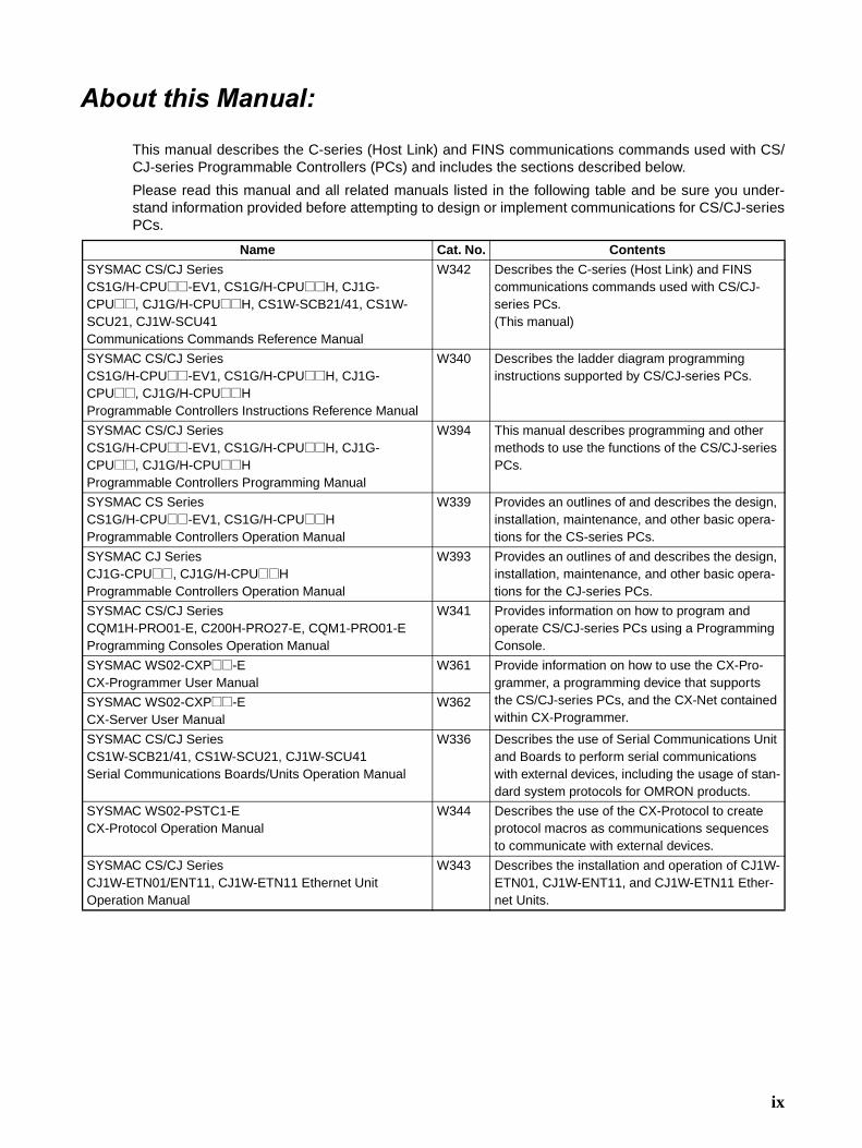
This manual describes the C-series (Host Link) and FINS communications commands used with CS/CJ-series Programmable Controllers (PCs) and includes the sections described below.
Please read this manual and all related manuals listed in the following table and be sure you under-stand information provided before attempting to design or implement communications for CS/CJ-seriesPCs.
Name Cat. No. Contents
SYSMAC CS/CJ Series CS1G/H-CPU@@-EV1, CS1G/H-CPU@@H, CJ1G-CPU@@, CJ1G/H-CPU@@H, CS1W-SCB21/41, CS1W-SCU21, CJ1W-SCU41Communications Commands Reference Manual
W342 Describes the C-series (Host Link) and FINS communications commands used with CS/CJ-series PCs.(This manual)
SYSMAC CS/CJ Series CS1G/H-CPU@@-EV1, CS1G/H-CPU@@H, CJ1G-CPU@@, CJ1G/H-CPU@@H Programmable Controllers Instructions Reference Manual
W340 Describes the ladder diagram programming instructions supported by CS/CJ-series PCs.
SYSMAC CS/CJ Series CS1G/H-CPU@@-EV1, CS1G/H-CPU@@H, CJ1G-CPU@@, CJ1G/H-CPU@@H Programmable Controllers Programming Manual
W394 This manual describes programming and other methods to use the functions of the CS/CJ-series PCs.
SYSMAC CS Series CS1G/H-CPU@@-EV1, CS1G/H-CPU@@HProgrammable Controllers Operation Manual
W339 Provides an outlines of and describes the design, installation, maintenance, and other basic opera-tions for the CS-series PCs.
SYSMAC CJ Series CJ1G-CPU@@, CJ1G/H-CPU@@HProgrammable Controllers Operation Manual
W393 Provides an outlines of and describes the design, installation, maintenance, and other basic opera-tions for the CJ-series PCs.
SYSMAC CS/CJ Series CQM1H-PRO01-E, C200H-PRO27-E, CQM1-PRO01-EProgramming Consoles Operation Manual
W341 Provides information on how to program and operate CS/CJ-series PCs using a Programming Console.
SYSMAC WS02-CXP@@-ECX-Programmer User Manual
W361 Provide information on how to use the CX-Pro-grammer, a programming device that supports the CS/CJ-series PCs, and the CX-Net contained within CX-Programmer.
SYSMAC WS02-CXP@@-ECX-Server User Manual
W362
SYSMAC CS/CJ Series CS1W-SCB21/41, CS1W-SCU21, CJ1W-SCU41Serial Communications Boards/Units Operation Manual
W336 Describes the use of Serial Communications Unit and Boards to perform serial communications with external devices, including the usage of stan-dard system protocols for OMRON products.
SYSMAC WS02-PSTC1-ECX-Protocol Operation Manual
W344 Describes the use of the CX-Protocol to create protocol macros as communications sequences to communicate with external devices.
SYSMAC CS/CJ Series CJ1W-ETN01/ENT11, CJ1W-ETN11 Ethernet Unit Operation Manual
W343 Describes the installation and operation of CJ1W-ETN01, CJ1W-ENT11, and CJ1W-ETN11 Ether-net Units.
ix

�����������������������������
Section 1 introduces the C-mode commands and FINS commands, and explains the relationshipbetween them.
Section 2 provides an overview of C-mode commands.
Section 3 provides an overview of FINS commands.
Section 4 provides detailed descriptions of the C-mode commands.
Section 5 provides detailed descriptions of the FINS commands.
!WARNING Failure to read and understand the information provided in this manual may result in per-sonal injury or death, damage to the product, or product failure. Please read each sectionin its entirety and be sure you understand the information provided in the section andrelated sections before attempting any of the procedures or operations given.
x

xi
PRECAUTIONS
This section provides general precautions for using the CS/CJ-series Programmable Controllers (PCs) and related devices.
The information contained in this section is important for the safe and reliable application of ProgrammableControllers. You must read this section and understand the information contained before attempting to set up oroperate a PC system.
1 Intended Audience . . . . . . . . . . . . . . . . . . . . . . . . . . . . . . . . . . . . . . . . . . . . . xii2 General Precautions . . . . . . . . . . . . . . . . . . . . . . . . . . . . . . . . . . . . . . . . . . . . xii3 Safety Precautions. . . . . . . . . . . . . . . . . . . . . . . . . . . . . . . . . . . . . . . . . . . . . . xii4 Operating Environment Precautions . . . . . . . . . . . . . . . . . . . . . . . . . . . . . . . . xiii5 Application Precautions . . . . . . . . . . . . . . . . . . . . . . . . . . . . . . . . . . . . . . . . . xiv

Intended Audience 1
1 Intended AudienceThis manual is intended for the following personnel, who must also haveknowledge of electrical systems (an electrical engineer or the equivalent).
• Personnel in charge of installing FA systems.
• Personnel in charge of designing FA systems.
• Personnel in charge of managing FA systems and facilities.
2 General PrecautionsThe user must operate the product according to the performance specifica-tions described in the operation manuals.
Before using the product under conditions which are not described in themanual or applying the product to nuclear control systems, railroad systems,aviation systems, vehicles, combustion systems, medical equipment, amuse-ment machines, safety equipment, and other systems, machines, and equip-ment that may have a serious influence on lives and property if usedimproperly, consult your OMRON representative.
Make sure that the ratings and performance characteristics of the product aresufficient for the systems, machines, and equipment, and be sure to providethe systems, machines, and equipment with double safety mechanisms.
This manual provides information for programming and operating the Unit. Besure to read this manual before attempting to use the Unit and keep this man-ual close at hand for reference during operation.
!WARNING It is extremely important that a PC and all PC Units be used for the specifiedpurpose and under the specified conditions, especially in applications that candirectly or indirectly affect human life. You must consult with your OMRONrepresentative before applying a PC System to the above-mentioned applica-tions.
3 Safety Precautions
!WARNING The CPU Unit refreshes I/O even when the program is stopped (i.e., even inPROGRAM mode). Confirm safety thoroughly in advance before changing thestatus of any part of memory allocated to I/O Units, Special I/O Units, or CPUBus Units. Any changes to the data allocated to any Unit may result in unex-pected operation of the loads connected to the Unit. Any of the following oper-ation may result in changes to memory status.
• Transferring I/O memory data to the CPU Unit from a ProgrammingDevice.
• Changing present values in memory from a Programming Device.
• Force-setting/-resetting bits from a Programming Device.
• Transferring I/O memory files from a Memory Card or EM file memory tothe CPU Unit.
• Transferring I/O memory from a host computer or from another PC on anetwork.
!WARNING Do not attempt to take any Unit apart while the power is being supplied. Doingso may result in electric shock.
xii

Operating Environment Precautions 4
!WARNING Do not touch any of the terminals or terminal blocks while the power is beingsupplied. Doing so may result in electric shock.
!WARNING Do not attempt to disassemble, repair, or modify any Units. Any attempt to doso may result in malfunction, fire, or electric shock.
!WARNING Do not touch the Power Supply Unit while power is being supplied or immedi-ately after power has been turned OFF. Doing so may result in electric shock.
!Caution Execute online edit only after confirming that no adverse effects will becaused by extending the cycle time. Otherwise, the input signals may not bereadable.
!Caution Confirm safety at the destination node before transferring a program toanother node or changing contents of the I/O memory area. Doing either ofthese without confirming safety may result in injury.
!Caution Tighten the screws on the terminal block of the AC Power Supply Unit to thetorque specified in the operation manual. Loose screws may result in burningor malfunction.
4 Operating Environment Precautions
!Caution Do not operate the control system in the following places:
• Locations subject to direct sunlight.
• Locations subject to temperatures or humidity outside the range specifiedin the specifications.
• Locations subject to condensation as the result of severe changes in tem-perature.
• Locations subject to corrosive or flammable gases.
• Locations subject to dust (especially iron dust) or salts.
• Locations subject to exposure to water, oil, or chemicals.
• Locations subject to shock or vibration.
!Caution Take appropriate and sufficient countermeasures when installing systems inthe following locations:
• Locations subject to static electricity or other forms of noise.
• Locations subject to strong electromagnetic fields.
• Locations subject to possible exposure to radioactivity.
• Locations close to power supplies.
!Caution The operating environment of the PC System can have a large effect on thelongevity and reliability of the system. Improper operating environments canlead to malfunction, failure, and other unforeseeable problems with the PCSystem. Be sure that the operating environment is within the specified condi-tions at installation and remains within the specified conditions during the lifeof the system.
xiii

Application Precautions 5
5 Application PrecautionsObserve the following precautions when using the PC System.
• You must use the CX-Programmer (programming software that runs onWindows) if you need to program more than one task. A ProgrammingConsole can be used to program only one cyclic task plus interrupt tasks.A Programming Console can, however, be used to edit multitask pro-grams originally created with the CX-Programmer.
!WARNING Always heed these precautions. Failure to abide by the following precautionscould lead to serious or possibly fatal injury.
• Always connect to a class-3 ground (to 100 � or less) when installing theUnits. Not connecting to a class-3 ground may result in electric shock.
• A class-3 ground (to 100 � or less) must be installed when shorting theGR and LG terminals on the Power Supply Unit.
• Always turn OFF the power supply to the PC before attempting any of thefollowing. Not turning OFF the power supply may result in malfunction orelectric shock.
• Mounting or dismounting Power Supply Units, I/O Units, CPU Units, In-ner Boards, or any other Units.
• Assembling the Units.
• Setting DIP switches or rotary switches.
• Connecting cables or wiring the system.
• Connecting or disconnecting the connectors.
!Caution Failure to abide by the following precautions could lead to faulty operation ofthe PC or the system, or could damage the PC or PC Units. Always heedthese precautions.
• When using a CS-series CS1 CPU Unit for the first time, install theCS1W-BAT01 Battery provided with the Unit and clear all memory areasfrom a Programming Device before starting to program. (Not required forCJ-series CPU Units.)
• When using the internal clock for a CS-series CS1 CPU Unit, turn ONpower after installing the battery and set the clock from a ProgrammingDevice or using the DATE(735) instruction. The clock will not start until thetime has been set. (Not required for CJ-series CPU Units.)
• Always turn ON power to the PC before turning ON power to the controlsystem. If the PC power supply is turned ON after the control power sup-ply, temporary errors may result in control system signals because theoutput terminals on DC Output Units and other Units will momentarily turnON when power is turned ON to the PC.
• Fail-safe measures must be taken by the customer to ensure safety in theevent that outputs from Output Units remain ON as a result of internal cir-cuit failures, which can occur in relays, transistors, and other elements.
• Fail-safe measures must be taken by the customer to ensure safety in theevent of incorrect, missing, or abnormal signals caused by broken signallines, momentary power interruptions, or other causes.
xiv

Application Precautions 5
• Interlock circuits, limit circuits, and similar safety measures in external cir-cuits (i.e., not in the Programmable Controller) must be provided by thecustomer.
• Do not turn OFF the power supply to the PC when data is being trans-ferred. In particular, do not turn OFF the power supply when reading orwriting a Memory Card. Also, do not remove the Memory Card when theBUSY indicator is lit. To remove a Memory Card, first press the memorycard power supply switch and then wait for the BUSY indicator to go outbefore removing the Memory Card.
• If the I/O Hold Bit is turned ON, the outputs from the PC will not be turnedOFF and will maintain their previous status when the PC is switched fromRUN or MONITOR mode to PROGRAM mode. Make sure that the exter-nal loads will not produce dangerous conditions when this occurs. (Whenoperation stops for a fatal error, including those produced with theFALS(007) instruction, all outputs from Output Unit will be turned OFFand only the internal output status will be maintained.)
• When supplying power at 200 to 240 VAC for CS-series PCs, alwaysremove the metal jumper from the voltage selector terminals. The productwill be destroyed if 200 to 240 VAC is supplied while the metal jumper isattached.
• Always use the power supply voltages specified in the operation manuals.An incorrect voltage may result in malfunction or burning.
• Take appropriate measures to ensure that the specified power with therated voltage and frequency is supplied. Be particularly careful in placeswhere the power supply is unstable. An incorrect power supply may resultin malfunction.
• Install external breakers and take other safety measures against short-cir-cuiting in external wiring. Insufficient safety measures against short-cir-cuiting may result in burning.
• Do not apply voltages to the Input Units in excess of the rated input volt-age. Excess voltages may result in burning.
• Do not apply voltages or connect loads to the Output Units in excess ofthe maximum switching capacity. Excess voltage or loads may result inburning.
• Disconnect the functional ground terminal when performing withstandvoltage tests. Not disconnecting the functional ground terminal may resultin burning.
• Install the Units properly as specified in the operation manuals. Improperinstallation of the Units may result in malfunction.
• Be sure that all the mounting screws, terminal screws, and cable connec-tor screws are tightened to the torque specified in the relevant manuals.Incorrect tightening torque may result in malfunction.
• Leave the label attached to the Unit when wiring. Removing the label mayresult in malfunction if foreign matter enters the Unit.
• Remove the label after the completion of wiring to ensure proper heat dis-sipation. Leaving the label attached may result in malfunction.
• Use crimp terminals for wiring. Do not connect bare stranded wiresdirectly to terminals. Connection of bare stranded wires may result inburning.
• Wire all connections correctly.
• Double-check all wiring and switch settings before turning ON the powersupply. Incorrect wiring may result in burning.
xv
Application Precautions 5
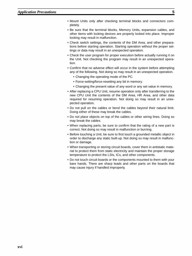
• Mount Units only after checking terminal blocks and connectors com-pletely.
• Be sure that the terminal blocks, Memory Units, expansion cables, andother items with locking devices are properly locked into place. Improperlocking may result in malfunction.
• Check switch settings, the contents of the DM Area, and other prepara-tions before starting operation. Starting operation without the proper set-tings or data may result in an unexpected operation.
• Check the user program for proper execution before actually running it onthe Unit. Not checking the program may result in an unexpected opera-tion.
• Confirm that no adverse effect will occur in the system before attemptingany of the following. Not doing so may result in an unexpected operation.
• Changing the operating mode of the PC.
• Force-setting/force-resetting any bit in memory.
• Changing the present value of any word or any set value in memory.
• After replacing a CPU Unit, resume operation only after transferring to thenew CPU Unit the contents of the DM Area, HR Area, and other datarequired for resuming operation. Not doing so may result in an unex-pected operation.
• Do not pull on the cables or bend the cables beyond their natural limit.Doing either of these may break the cables.
• Do not place objects on top of the cables or other wiring lines. Doing somay break the cables.
• When replacing parts, be sure to confirm that the rating of a new part iscorrect. Not doing so may result in malfunction or burning.
• Before touching a Unit, be sure to first touch a grounded metallic object inorder to discharge any static built-up. Not doing so may result in malfunc-tion or damage.
• When transporting or storing circuit boards, cover them in antistatic mate-rial to protect them from static electricity and maintain the proper storagetemperature to protect the LSIs, ICs, and other components.
• Do not touch circuit boards or the components mounted to them with yourbare hands. There are sharp leads and other parts on the boards thatmay cause injury if handled improperly.
xvi

1
SECTION 1Introduction
This section introduces the C-mode commands and FINS commands, and explains the relationship between them.
1-1 Overview of Communications Commands . . . . . . . . . . . . . . . . . . . . . . . . . . . 2
1-2 C-mode Commands. . . . . . . . . . . . . . . . . . . . . . . . . . . . . . . . . . . . . . . . . . . . . 2
1-3 FINS Commands. . . . . . . . . . . . . . . . . . . . . . . . . . . . . . . . . . . . . . . . . . . . . . . 4

Overview of Communications Commands Section 1-1
1-1 Overview of Communications Commands
Communications Commands Addressed to CS/CJ-series PCsA CS/CJ-series CPU Unit can receive the following communications com-mands.
C-mode Commands C-mode commands are specialized Host Link communications commands.They are issued by a host computer and sent to a CPU Unit. The devices thatcan be connected for serial communications are the CPU Unit, a Serial Com-munications Unit, and a Serial Communications Board.
FINS Commands FINS commands are message service communications commands. They donot depend on a particular transmission path. They can be used for communi-cations on various networks (Controller Link, Ethernet, etc.) and for serialcommunications (Host Link). They can be issued from a CPU Unit, Special I/OUnit, or host computer, and they can also be sent to any of these. The specificcommands that can be sent depend on the destination.
This manual explains commands sent to CS/CJ-series CPU Units, when thecommands are issued from a CPU Unit or a host computer connected by HostLink.
Note When the source of the commands is a CPU Unit, the FINS commands aresent by means of CMND(490)/SEND(090)/RECV(098). When the source is ahost computer, the FINS commands are issued using Host Link protocol.
1-2 C-mode CommandsThe following table lists the C-mode (Host Link) commands. For details, referto SECTION 4 C-mode Commands.
Communications commands
C-mode commands via Host Link
FINS commandsVia CMND(490)/SEND(090)/RECV(098)
Via Host Link
Type Header code
Name Function
I/O memoryreading
RR CIO AREA READ Reads the specified number of words beginning with the designated CIO word.
RL LR AREA READ Reads the specified number of words beginning with the designated LR word.
RH HR AREA READ Reads the specified number of words beginning with the designated HR word.
RC TIMER/COUNTER PV READ Reads the specified number of words of the timer/counter PV beginning with the designated word.
RG TIMER/COUNTER STATUS READ Reads the specified number of words of the timer/counter status beginning with the designated word.
RD DM AREA READ Reads the specified number of words beginning with the designated DM word.
RJ AR AREA READ Reads the specified number of words beginning with the designated AR word.
RE EM AREA READ Reads the specified number of words beginning with the designated EM word.
2

C-mode Commands Section 1-2
I/O memorywriting
WR CIO AREA WRITE Writes the specified data in word units beginning with the designated CIO word.
WL LR AREA WRITE Writes the specified data in word units beginning with the designated LR word.
WH HR AREA WRITE Writes the specified data in word units beginning with the designated HR word.
WC TIMER/COUNTER PV WRITE Writes the specified timer/counter PV data in word units beginning with the designated word.
WD DM AREA WRITE Writes the specified data in word units beginning with the designated DM word.
WJ AR AREA WRITE Writes the specified data in word units beginning with the designated AR word.
WE EM AREA WRITE Writes the specified data in word units beginning with the designated EM word.
Timer/counter SV reading
R# TIMER/COUNTER SV READ 1 Reads in four digits BCD the constant SV that is written as an operand of the designated timer/counter instruction.
R$ TIMER/COUNTER SV READ 2 Finds the specified timer/counter instruction, begin-ning with the designated program address, and reads the constant SV in four digits or the word in which the SV is stored.
R% TIMER/COUNTER SV READ 3 Finds the specified timer/counter instruction, begin-ning with the designated program address, and reads the constant SV in four digits (BCD) or the word in which the SV is stored.
Timer/counter SV changing
W# TIMER/COUNTER SV CHANGE 1 Changes the SV of the specified timer/counter instruction to a new constant SV.
W$ TIMER/COUNTER SV CHANGE 2 Finds the specified timer/counter instruction, begin-ning with the designated program address in the user program, and changes the constant SV in four digits (BCD) or the word in which the SV is stored to a new constant SV or storage word.
W% TIMER/COUNTER SV CHANGE 3 Finds the specified timer/counter instruction, begin-ning with the designated program address in the user program, and changes the constant SV in four digits (BCD) or the word in which the SV is stored to a new constant SV or storage word.
CPU Unit status MS STATUS READ Reads the CPU Unit’s operating conditions (operat-ing mode, forced set/reset status, and fatal errors).
SC STATUS CHANGE Changes the CPU Unit’s operating mode.
MF ERROR READ Reads the CPU Unit’s error information (i.e., all fatal or non-fatal errors currently in effect).
Forcedset/reset
KS FORCED SET Forcibly sets one designated bit.
KR FORCED RESET Forcibly resets one designated bit.
FK MULTIPLE FORCED SET/RESET Forcibly sets/resets/cancels multiple designated bits.
KC FORCED SET/RESET CANCEL Cancels all forced set/reset status.
PC model code reading
MM PC MODEL READ Reads the model code of the CPU Unit.
Testing TS TEST Returns, just as it is, a single block that was sent from the host computer.
Type Header code
Name Function
3

FINS Commands Section 1-3
1-3 FINS CommandsThe following table lists the FINS commands. For details, refer to SECTION 5FINS Commands.
Program area accessing
RP PROGRAM READ Reads, in one batch, the contents of the CPU Unit’s user program at the machine language (object) level.
WP PROGRAM WRITE Writes into the CPU Unit’s user program area the machine language (object) sent from the host com-puter.
I/O table creation MI I/O TABLE CREATE Creates an I/O table with the contents of the actual I/O configuration.
I/O memory area registration and reading
QQMR REGISTER I/O MEMORY Registers the I/O memory words or bits that are to be read.
QQIR READ I/O MEMORY Reads the registered I/O memory words/bits all at once.
Host Link commu-nicationsprocessing
XZ ABORT (command only) Aborts the operation being performed by a Host Link command, and then returns to the initial status.
�� INITIALIZE (command only) Initializes the transfer control procedures for all Host Link Units.
IC Undefined command (response only)
This is the response when the command header code cannot be decoded.
Type Header code
Name Function
Type Command code
Name Function
MR SR
I/O memory area access
01 01 MEMORY AREA READ Reads the contents of consecutive I/O memory area words.
01 02 MEMORY AREA WRITE Writes the contents of consecutive I/O memory area words.
01 03 MEMORY AREA FILL Writes the same data to the specified range of I/O memory area words.
01 04 MULTIPLE MEMORY AREA READ Reads the contents of specified non-consecutive I/O memory area words.
01 05 MEMORY AREA TRANSFER Copies the contents of consecutive I/O memory area words to another I/O memory area.
Parameter area access
02 01 PARAMETER AREA READ Reads the contents of consecutive parameter area words.
02 02 PARAMETER AREA WRITE Writes the contents of consecutive parameter area words.
02 03 PARAMETER AREA FILL (CLEAR) Clears the specified range of parameter area words.
Program area access
03 06 PROGRAM AREA READ Reads the UM (User Memory) area.
03 07 PROGRAM AREA WRITE Writes to the UM (User Memory) area.
03 08 PROGRAM AREA CLEAR Clears a specified range of the UM (User Memory) area.
Operating mode changes
04 01 RUN Changes the CPU Unit’s operating mode to RUN or MONITOR.
04 02 STOP Changes the CPU Unit’s operating mode to PROGRAM.
Machine configura-tion reading
05 01 CPU UNIT DATA READ Reads CPU Unit data.
05 02 CONNECTION DATA READ Reads the model numbers of the device corresponding to addresses.
4

FINS Commands Section 1-3
Status reading 06 01 CPU UNIT STATUS READ Reads the status of the CPU Unit.
06 20 CYCLE TIME READ Reads the maximum, minimum, and average cycle time.
Time data access 07 01 CLOCK READ Reads the present year, month, date, minute, second, and day of the week.
07 02 CLOCK WRITE Changes the present year, month, date, minute, second, or day of the week.
Message display 09 20 MESSAGE READ/CLEAR Reads and clears messages, and reads FAL/FALS messages.
Access rights 0C 01 ACCESS RIGHT ACQUIRE Acquires the access right as long as no other device holds it.
0C 02 ACCESS RIGHT FORCED ACQUIRE Acquires the access right even if another device already holds it.
0C 03 ACCESS RIGHT RELEASE Releases the access right that has been acquire.
Error log 21 01 ERROR CLEAR Clears errors or error messages.
21 02 ERROR LOG READ Reads the error log.
21 03 ERROR LOG CLEAR Clears all error log records.
File memory 22 01 FILE NAME READ Reads file device data.
22 02 SINGLE FILE READ Reads a specified length of file data from a specified position within a single file.
22 03 SINGLE FILE WRITE Writes a specified length of file data from a specified position within a single file.
22 04 FILE MEMORY FORMAT Formats (initializes) the file device.
22 05 FILE DELETE Deletes specified files stored in the file device.
22 07 FILE COPY Copies files from one file device to another file device in the same system.
22 08 FILE NAME CHANGE Changes a file name.
22 0A MEMORY AREA–FILE TRANSFER Transfers or compares data between the I/O memory area and the file device.
22 0B PARAMETER AREA–FILE TRANSFER Transfers or compares data between the parameter area and the file device.
22 0C PROGRAM AREA–FILE TRANSFER Transfers or compares data between the UM (User Memory) area and the file device.
22 15 DIRECTORY CREATE/DELETE Creates or deletes a directory.
Debugging 23 01 FORCED SET/RESET Force-sets or force-resets bits, or releases force-set status.
23 02 FORCED SET/RESET CANCEL Cancels all bits that have been force-set or force-reset.
Type Command code
Name Function
MR SR
5


7
SECTION 2Overview of C-mode Commands
This section provides an overview of C-mode (Host Link) commands.
2-1 C-mode Commands. . . . . . . . . . . . . . . . . . . . . . . . . . . . . . . . . . . . . . . . . . . . . 8
2-2 Command/Response Formats . . . . . . . . . . . . . . . . . . . . . . . . . . . . . . . . . . . . . 9
2-3 Application Example. . . . . . . . . . . . . . . . . . . . . . . . . . . . . . . . . . . . . . . . . . . . 14
2-4 Precautions in Using Programs from Previous PC Models . . . . . . . . . . . . . . 15
2-4-1 Using Host Computer Programs Written for C-series Host Link Units 15
2-4-2 C-mode Command Support . . . . . . . . . . . . . . . . . . . . . . . . . . . . . . . 18

C-mode Commands Section 2-1
2-1 C-mode CommandsC-mode (Host Link) commands form a command/response system for serialcommunications (Host Link Mode) to perform various control operationsbetween a CPU Unit and a host computer directly connected to it. Theseoperations include reading from and writing to I/O memory, changing operat-ing modes, executing forced set and forced reset operations, and so on.
Unlike FINS commands, C-mode commands can only be addressed to a CPUUnit, and they cannot be used for message service outside of the local net-work. They cannot be used for functions such as file operations.
C-mode (Host Link) commands can be sent from a host computer connectedto a CS/CJ-series Host Link Unit. Up to 32 PCs (Host Link Units) can be con-nected to a single host computer. For identification, each Host Link Unit isassigned a unit number from 0 to 31.
The length of a single unit of a command or response exchange is called a“frame.” A single frame contains a maximum of 131 characters of data. Char-acters are sent and received as ASCII.
Note For a CS/CJ-series PC, a “Host Link Unit” can be the CPU Unit, a Serial Com-munications Unit, or a Serial Communications Board.
A maximum of 30 words of data can be transferred for the first commandframe and a maximum of 31 words of data can be transferred for other com-mand frames when reading or writing word data in I/O memory. When read-ing/writing more than 30 words of data, the data transfer will be processed inmultiple transmissions, with 30 words in the first and up to 31 words in each ofthe following transmissions until the number of words set in the command hasbeen processed.
The frame formats for Host Link commands sent from a host computer andresponses returned by the PC receiving the commands are explained in thefollowing section.
Response
C-mode command
Response
C-mode command
8

Command/Response Formats Section 2-2
inator
2-2 Command/Response FormatsSingle-frame Commands If a command is not more than 131 characters long, communications can be
completed by sending a single command frame. This is called a “single-framecommand.”
Command Frame Format
• @: Must be attached at the beginning of the command.
• Unit number: Set in BCD from 0 to 31 for each Host Link Unit.
• Header code: Specified in two characters.
• Text: Set parameters corresponding to command code.
• FCS: Calculate 2-character FCS (frame check sequence) at hostcomputer. For details on calculating FCS, refer to FCS Cal-culations later in this section.
• Terminator: Set “*” and CR (CHR$(13)) as two characters to indicatethe end of the command.
Single-frame Response If a response is not more than 131 characters long, the communications canbe completed by returning one response frame. This is called a “single-frameresponse.”
Response Frame Format
• @: Must be attached at the beginning of the response.
• Unit number: Set in BCD from 0 to 31 for each Host Link Unit.
• Header code: The command code that was received is returned.
• End code: The results (error status, etc.) of command execution isreturned.
• Text: Returned only if there is read data.
• FCS: The 2-character FCS (frame check sequence) is returned.
• Terminator: Two characters indicating the end of the command, “*” andCR (CHR$(13)), are returned.
Unit number (BCD)
Header codeText
FCS
Terminator
Unit number (BCD)
End code (hexadecimal)Text
FCS
Term
Header code
9

Command/Response Formats Section 2-2
Error Response Formant If a reception error or an error in executing the command occurs, a responseis returned with no text.
Partitioned Commands If a command is longer than 131 characters, the command’s text is partitionedby sending a delimiter [CR code, CHR$(13)] instead of a terminator at the endof each command frame until the last one. A terminator is sent at the end ofthe last frame. The procedure is given below for three command frames.
Note When sending command frames for writing (WR, WL, WC, WD, etc.), be care-ful not to partition into separate frames data that is to be written into the sameword.
1,2,3... 1. From the host computer, attach a delimiter (CR) at the end of commandframe 1 and send the frame.
2. When the PC receives this delimiter (CR), it will return only a delimiter (CR)to the host computer.
3. From the host computer, attach a delimiter (CR) at the end of commandframe 2 and send the frame.
4. When the PC receives this delimiter (CR), it will return only a delimiter (CR)to the host computer.
5. From the host computer, attach a terminator (*CR) at the end of commandframe 3 and send the frame.
6. When the PC receives this terminator (*CR), it will return the response for-mat with a terminator (*CR) attached to the end.
Unit number (BCD)
End code (hexadecimal)
FCS
Terminator
Header code
10

Command/Response Formats Section 2-2
The following diagram shows the command format when there are more than131 characters.
Note A “delimiter” is a CR code [CHR$(13)] sent as a single character to indicatethe middle of a command or response.
Partitioned Responses If a response is more than 131 characters long, the response from the PC ispartitioned by returning a delimiter (CR code, CHR$(13)) instead of a termina-tor at the end of each frame until the last one. A terminator is returned at theend of the last frame.
In the following example procedure, the response is partitioned into threeframes.
1,2,3... 1. When the PC receives the command frame from the host computer, it re-turns response frame 1 with a delimiter (CR) at the end to the host com-puter.
2. Only a delimiter (CR) is sent from the host computer to the PC.
3. When the PC receives this delimiter (CR), it returns response frame 2 witha delimiter (CR) at the end to the host computer.
4. Only a delimiter (CR) is sent from the host computer to the PC.
5. When the PC receives this delimiter (CR), it returns response frame 3 witha terminator (*CR) at the end to the host computer.
128 characters max. 128 characters max.
PC
@U
nit n
umbe
r
Hea
der
code
Command frame 1 Command frame 2 Command frame 3
Response frame
Host Computer F
CS
Del
imite
r
Text
Text
FC
S
Del
imite
r
Text
FC
S
Term
inat
or
Del
imite
r
Del
imite
r
@U
nit n
umbe
r
Term
inat
or
Text
FC
S
End
cod
e
Hea
der
code
11

Command/Response Formats Section 2-2
The following diagram shows the response format when there are more than131 characters.
Note 1. Frames in partitioned commands or responses must have not more than128 characters including the delimiter/terminator.
2. Delimiters from the host computer are detected by the presence of a CRcode. The delimiter will be detected even if there is data in front of it.
128 characters max. 128 characters max.
PC
Command frame
Response frame 3
131 characters max.
Response frame 2Response frame 1D
elim
iter
@U
nit n
umbe
r
Term
inat
or
Text
FC
S
Hea
der
code
Hos
t com
pute
r
Del
imite
r
@U
nit n
umbe
r
Del
imite
r
Text
FC
S
End
cod
e
Hea
der
code
Del
imite
r
Text
FC
S
Term
inat
or
Text
FC
S
12

Command/Response Formats Section 2-2
FCS Calculations The PC calculates the FCS (Frame Check Sequence) value for each com-mand frame it receives, and it checks for errors by comparing that value withthe FCS value sent with the command frame. The host computer must calcu-late the FCS value when sending a command frame.
Also, when checking for errors in response frames, the host computer mustcalculate the FCS value for each response frame it receives and compare thatvalue to the FCS value sent in the response frame.
Note The FCS is an 8-bit value converted into two ASCII characters. The 8-bitvalue is the result of an exclusive OR sequentially performed between eachcharacter in a transmission, from the first character in the frame to the lastcharacter of the text in that frame. Non-ASCII data, however, may sometimesbe sent in the text data. If the data length is 7 bits, the leftmost bit of eachcharacter is masked before the FCS is calculated.
Unit number
Header codeText
FCS
Terminator
FCS calculation range
ASCIICode
Calculation result (See note.)
The value is converted to hexadecimal and handled as ASCII.
@ 40 0100 0000 EOR1 31 0011 0001 EOR0 30 0011 0000 EORR 52 0101 0010
1 31 0011 0001 0100 0010
4 Hex 2 Hex
•••
13

Application Example Section 2-3
2-3 Application Example
Sending a Host Link Command from a Host ComputerIn this example program, a Host Link command is sent from a host computerand a response is received.
10 ’CS1 SAMPLE PROGRAM FOR EXCEPTION20 CLOSE30 CLS40 OPEN “COM:E73”AS#150 *KEYIIN60 INPUT ”DATA–”,S70 IF S$=””THEN GOTO 19080 PRINT ”SEND DATA=”;S$90 ST$=S$100 INPUT ”SEND OK? Y or N?=”,BS110 IF B$=”Y” THEN GOTO 130 ELSE GOTO *KEYIN120 S$=ST$130 PRINT #T,S$ Sends command to PC.140 INPUT #1,R$ Receives command from PC.150 PRINT ”RECV DATA=”;R$160 IF MID$(R$,4,2)=”EX”THEN GOTO 210 Identifies command.170 IF RIGHT$(R$,1)<>”*”THEN S$=””:GOTO 130180 GOTO *KEYIN190 CLOSE 1200 END210 PRINT ”EXCEPTION!!DATA”220 GOTO 140
Explanation
1,2,3... 1. The host computer’s transmission/reception program is started up, and theHost Link command is input.
2. The Host Link command that was input is sent to the PC, and the data thatis received is displayed on the screen.
Note The example program up to this point does not include an error processingroutine in case reception is not normal (e.g., if there is no FCS). Include errorprocessing routines when creating an actual program.
400 *FCSCHCK410 L=LEN(RESPONSE$) Transmission/reception data420 Q=0:FCSCK$=””430 A$=RIGHT$(RESPONSE$,1)440 PRINT RESPONSE$,A$,L450 IF A$=”*”THEN LENGS=LEN(RESPONSE$)–3 ELSE LENGS=LEN(RESPONSE$)–2460 FCSP$=MID$(RESPONSE$,LENGS+1,2) FCS data that is received470 FOR I=1 TO LENGS Number of characters in FCS calculation480 Q=ASC(MID$(RESPONSE$1,1))XOR Q490 NEXT 1500 FCSD$=HEX$(Q)510 IF LEN(FCSD$) =1 THEN FCSD$=”0”+FCSD$ FCS calculation result520 IF FCSD$<>FCSP$ THEN FCSCK$=”ERR”530 PRINT ”FCSD$=”;FCSD$,”FCSP$=”;FCSP$,”FCSCK$=”;FCSCK$
Normal FCS reception: “ ” (space); abnormal FCS reception: “ERR”540 RETURN
14

Precautions in Using Programs from Previous PC Models Section 2-4
2-4 Precautions in Using Programs from Previous PC Models
2-4-1 Using Host Computer Programs Written for C-series Host Link Units
Number of Words per FrameThe numbers of words of text in each frame when using the following com-mands to read I/O memory are different for C-series Host Link Units and CS/CJ-series Units. The C-series Host Link Units will handle 29 words in the firstframe and 30 words in following frames, but CS/CJ-series Units will handle30 words in the first frame and 31 words in following frames.
The differences in the length of data read with each frame can cause hostcomputer programs previously used with C-series Host Link Unit to not workcorrectly with CS/CJ-series Units. Check the operations of the host computerprograms and correct them if necessary.
Header code Name
RR CIO AREA READ
RL LR AREA READ
RH HR AREA READ
RC TIMER/COUNTER PV READ
RG TIMER/COUNTER STATUS READ
Note: With the RG command, the number of words per frame is different to that for other C-mode commands. For details refer to Words per Frame for C-mode RG Command below.
RD DM AREA READ
RJ AR AREA READ
15

Precautions in Using Programs from Previous PC Models Section 2-4
Words per Frame for C-mode Commands (Except RG Command)
Words per Frame for C-mode RG Command
Units C Series CS/CJ Series CVM1 and CV Series Data words per frame
1st frame Other frames
C-series Host Link Units
C200H- LK101/LK201/LK202 Host Link Units
C500-LK103/LK203 Host Link Units3G2A5-LK101/LK201 Host Link Units3G2A6- LK101/LK201/LK202 Host Link Units
--- --- 29 words 30 words
Other Boards and Units
SRM1 built-in portsCPM1 built-in ports
CPM1A built-in ports
CQM1-CPU@@ built-in ports
C200HS-CPU@@ built-in portsC200HX/HG/HE-CPU@@ built-in ports
C200HW-COM@@ Communications Board ports
CS1G/H-CPU@@H built-in ports
CS1G/H-CPU@@ built-in ports
CJ1G/H-CPU@@H built-in portsCJ1G-CPU@@ built-in ports
CS1W-SCB21/41 Serial Communica-tions Board ports
CS1W-SCU21 Serial Communications Unit ports
CJ1W-SCU41 Serial Communications Unit ports
CVM1-CPU@@ built-in ports
CV-CPU@@ built-in portsCV500-LK201 Host Link Unit
30 words 31 words
Units C Series CS/CJ Series CVM1 and CV Series Data words per frame
1st frame Other frames
C-series Host Link Units
C200H- LK101/LK201/LK202 Host Link Units
--- --- 89 words 60 words
C500-LK103/LK203 Host Link Units3G2A5-LK101/LK201 Host Link Units3G2A6- LK101/LK201/LK202 Host Link Units
--- --- 89 words 89 words
Other Boards and Units
SRM1 built-in portsCPM1 built-in ports
CPM1A built-in ports
CQM1-CPU@@ built-in ports
CQM1H-CPU@@ built-in ports
CQM1H-SCB@@ built-in portsC200HX/HG/HE-CPU@@ built-in ports
C200HW-COM@@ Communications Board ports
CS1G/H-CPU@@H built-in ports
CS1G/H-CPU@@ built-in ports
CJ1G/H-CPU@@H built-in portsCJ1G-CPU@@ built-in ports
CS1W-SCB21/41 Serial Communica-tions Board ports
CS1W-SCU21 Serial Communications Unit ports
CJ1W-SCU41 Serial Communications Unit ports
CVM1-CPU@@ built-in ports
CV-CPU@@ built-in portsCV500-LK201 Host Link Unit
121 words 125 words
16

Precautions in Using Programs from Previous PC Models Section 2-4
Note The number of words per frame will be different in the following cases.
With CS/CJ-series CPU Unit built-in ports, CS/CJ-series Serial Communica-tions Units/Boards, C200HX/HG/HE CPU Unit built-in ports, or C200HS CPUUnit built-in ports, when 246 words of timer or counter completion flags areread, response is returned as shown in the following table.
The frame one before the last frame contains 124 words and the last framecontains 1 word. This also applies when the number of words is 246 + a multi-ple of 125 (i.e., 371 words, 496 words, 621 words, etc.).
With CS/CJ-series Unit built-in ports, when 121 words of timer or countercompletion flags are read, response is returned as shown in the followingtable.
With CVM1 and CV-series CPU Unit built-in ports or CVM1/CV-series HostLink Units, when 121 or 246 words of timer of counter completion flags areread, response is returned as shown in the following table.
Number of Words = 121
Number of Words = 246
The frame one before the last frame contains 125 words and the last framecontains the terminator only. This also applies when the number of words is246 + a multiple of 125 (i.e., 371 words, 496 words, 621 words, etc.). Forresponses containing the terminator only, “00*CR” (00 = FCS, CR = carriagereturn) is returned.
Response Format for MS CommandWith the MS command (STATUS READ), the response data format whenusing CVM1 or CV-series built-in ports or Host Link Units, is different to theresponse data format for other Units.
With CVM1 or CV-series built-in ports or Host Link Units, if FAL/FALS is notexecuted, spaces (ASCII 20) will be added to the response data. For otherUnits, FAL/FALS message data will added to response data only if FAL/FALSis executed.
1st frame 2nd frame 3rd frame
121 words 124 words 1 word
1st frame 2nd frame
120 words 1 word
1st frame 2nd frame
121 words 0 words (terminator only)
1st frame 2nd frame 3rd frame
121 words 125 words 0 words (terminator only)
17
Precautions in Using Programs from Previous PC Models Section 2-4
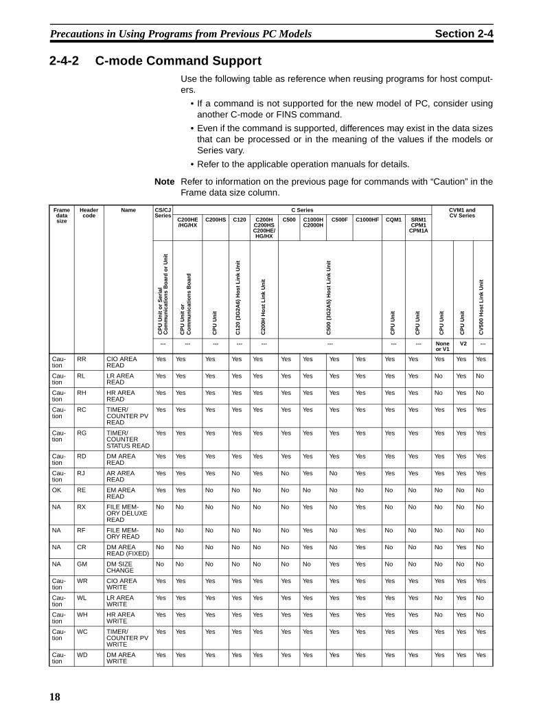
2-4-2 C-mode Command SupportUse the following table as reference when reusing programs for host comput-ers.
• If a command is not supported for the new model of PC, consider usinganother C-mode or FINS command.
• Even if the command is supported, differences may exist in the data sizesthat can be processed or in the meaning of the values if the models orSeries vary.
• Refer to the applicable operation manuals for details.
Note Refer to information on the previous page for commands with “Caution” in theFrame data size column.
Frame data size
Header code
Name CS/CJ Series
C Series CVM1 and CV Series
C200HE/HG/HX
C200HS C120 C200HC200HSC200HE/HG/HX
C500 C1000HC2000H
C500F C1000HF CQM1 SRM1CPM1
CPM1A
--- --- --- --- --- --- --- --- None or V1
V2 ---
Cau-tion
RR CIO AREA READ
Yes Yes Yes Yes Yes Yes Yes Yes Yes Yes Yes Yes Yes Yes
Cau-tion
RL LR AREA READ
Yes Yes Yes Yes Yes Yes Yes Yes Yes Yes Yes No Yes No
Cau-tion
RH HR AREA READ
Yes Yes Yes Yes Yes Yes Yes Yes Yes Yes Yes No Yes No
Cau-tion
RC TIMER/COUNTER PV READ
Yes Yes Yes Yes Yes Yes Yes Yes Yes Yes Yes Yes Yes Yes
Cau-tion
RG TIMER/COUNTER STATUS READ
Yes Yes Yes Yes Yes Yes Yes Yes Yes Yes Yes Yes Yes Yes
Cau-tion
RD DM AREA READ
Yes Yes Yes Yes Yes Yes Yes Yes Yes Yes Yes Yes Yes Yes
Cau-tion
RJ AR AREA READ
Yes Yes Yes No Yes No Yes No Yes Yes Yes Yes Yes Yes
OK RE EM AREA READ
Yes Yes No No No No No No No No No No No No
NA RX FILE MEM-ORY DELUXE READ
No No No No No No Yes No Yes No No No No No
NA RF FILE MEM-ORY READ
No No No No No No Yes No Yes No No No No No
NA CR DM AREA READ (FIXED)
No No No No No No Yes No Yes No No No Yes No
NA GM DM SIZE CHANGE
No No No No No No No Yes Yes No No No No No
Cau-tion
WR CIO AREA WRITE
Yes Yes Yes Yes Yes Yes Yes Yes Yes Yes Yes Yes Yes Yes
Cau-tion
WL LR AREA WRITE
Yes Yes Yes Yes Yes Yes Yes Yes Yes Yes Yes No Yes No
Cau-tion
WH HR AREA WRITE
Yes Yes Yes Yes Yes Yes Yes Yes Yes Yes Yes No Yes No
Cau-tion
WC TIMER/COUNTER PV WRITE
Yes Yes Yes Yes Yes Yes Yes Yes Yes Yes Yes Yes Yes Yes
Cau-tion
WD DM AREA WRITE
Yes Yes Yes Yes Yes Yes Yes Yes Yes Yes Yes Yes Yes Yes
CP
U U
nit
or
Ser
ial
Co
mm
un
icat
ion
s B
oar
d o
r U
nit
CP
U U
nit
or
Co
mm
un
icat
ion
s B
oar
d
CP
U U
nit
C12
0 (3
G2A
6) H
ost
Lin
k U
nit
C20
0H H
ost
Lin
k U
nit
C50
0 (3
G2A
5) H
ost
Lin
k U
nit
CP
U U
nit
CP
U U
nit
CP
U U
nit
CP
U U
nit
CV
500
Ho
st L
ink
Un
it
18

Precautions in Using Programs from Previous PC Models Section 2-4
Cau-tion
WJ AR AREA WRITE
Yes Yes Yes No No No Yes No Yes Yes Yes Yes Yes Yes
OK WE EM AREA WRITE
Yes Yes No No No No No No No No No No No No
NA R# TIMER/COUNTER SV READ 1
Yes Yes Yes Yes Yes Yes Yes Yes Yes Yes Yes No Yes No
NA R$ TIMER/COUNTER SV READ 2
Yes Yes Yes Yes Yes Yes Yes Yes Yes Yes Yes No Yes No
NA R% TIMER/COUNTER SV READ 3
Yes Yes Yes Yes Yes Yes Yes Yes Yes Yes No No Yes No
NA W# TIMER/COUNTER SV CHANGE 1
Yes Yes Yes Yes Yes Yes Yes Yes Yes Yes Yes No Yes No
NA W$ TIMER/COUNTER SV CHANGE 2
Yes Yes Yes Yes Yes Yes Yes Yes Yes Yes Yes No Yes No
NA W% TIMER/COUNTER SV CHANGE 3
Yes Yes Yes Yes Yes Yes Yes Yes Yes Yes No No Yes No
NA MS STATUS READ Yes Yes Yes Yes Yes Yes Yes Yes Yes Yes Yes Yes Yes Yes
NA SC STATUS CHANGE
Yes Yes Yes Yes Yes Yes Yes Yes Yes Yes Yes Yes Yes Yes
NA MF ERROR READ Yes Yes Yes Yes Yes Yes Yes Yes Yes Yes Yes Yes Yes Yes
NA KS FORCED SET Yes Yes Yes Yes Yes Yes Yes Yes Yes Yes Yes Yes Yes Yes
NA KR FORCED RESET
Yes Yes Yes Yes Yes Yes Yes Yes Yes Yes Yes Yes Yes Yes
NA FK MULTIPLE FORCED SET/RESET
Yes Yes Yes No Yes No No No No Yes Yes No Yes No
NA FR MULTIPLE FORCED SET/RESET STA-TUS READ
No Yes Yes No Yes No No No No No No No No No
NA KC FORCED SET/RESET CAN-CEL
Yes Yes Yes Yes Yes Yes Yes Yes Yes Yes Yes Yes Yes Yes
NA MM PC MODEL READ
Yes Yes Yes Yes Yes Yes Yes Yes Yes Yes Yes Yes Yes Yes
NA TS TEST Yes Yes Yes Yes Yes Yes Yes Yes Yes Yes Yes Yes Yes Yes
NA RP PROGRAM READ
Yes Yes Yes Yes Yes Yes Yes Yes Yes Yes Yes Yes Yes Yes
NA WP PROGRAM WRITE
Yes Yes Yes Yes Yes Yes Yes Yes Yes Yes Yes Yes Yes Yes
NA MI I/O TABLE CREATE
Yes Yes Yes Yes Yes Yes Yes Yes Yes No No Yes Yes Yes
NA QQMR/ QQIR
REGISTER/READ I/O MEMORY
Yes Yes Yes Yes Yes Yes Yes Yes Yes Yes Yes Yes Yes Yes
NA XZ ABORT (com-mand only)
Yes Yes Yes Yes Yes Yes Yes Yes Yes Yes Yes Yes Yes Yes
NA �� INITIALIZE (command only)
Yes Yes Yes Yes Yes Yes Yes Yes Yes Yes Yes Yes Yes Yes
Frame data size
Header code
Name CS/CJ Series
C Series CVM1 and CV Series
C200HE/HG/HX
C200HS C120 C200HC200HSC200HE/HG/HX
C500 C1000HC2000H
C500F C1000HF CQM1 SRM1CPM1
CPM1A
--- --- --- --- --- --- --- --- None or V1
V2 ---
CP
U U
nit
or
Ser
ial
Co
mm
un
icat
ion
s B
oar
d o
r U
nit
CP
U U
nit
or
Co
mm
un
icat
ion
s B
oar
d
CP
U U
nit
C12
0 (3
G2A
6) H
ost
Lin
k U
nit
C20
0H H
ost
Lin
k U
nit
C50
0 (3
G2A
5) H
ost
Lin
k U
nit
CP
U U
nit
CP
U U
nit
CP
U U
nit
CP
U U
nit
CV
500
Ho
st L
ink
Un
it
19

Precautions in Using Programs from Previous PC Models Section 2-4
Note The response data format for the MS command (STATUS READ) when usingCVM1 or CV-series built-in ports or Host Link Units, is different to theresponse data format for other Units. For details, refer to 4-3-23 STATUSREAD – – MS.
NA IC Undefined command (response only)
Yes Yes Yes Yes Yes Yes Yes Yes Yes Yes Yes Yes Yes Yes
NA EX TXD RESPONSE (response only)
No Yes No No No No No No No No No No No No
NA FA FINS MES-SAGE
Yes No No No No No No No No No No Yes Yes Yes
NA OF FINS MES-SAGE (slave- initiated)
Yes No No No No No No No No No No Yes Yes Yes
Frame data size
Header code
Name CS/CJ Series
C Series CVM1 and CV Series
C200HE/HG/HX
C200HS C120 C200HC200HSC200HE/HG/HX
C500 C1000HC2000H
C500F C1000HF CQM1 SRM1CPM1
CPM1A
--- --- --- --- --- --- --- --- None or V1
V2 ---
CP
U U
nit
or
Ser
ial
Co
mm
un
icat
ion
s B
oar
d o
r U
nit
CP
U U
nit
or
Co
mm
un
icat
ion
s B
oar
d
CP
U U
nit
C12
0 (3
G2A
6) H
ost
Lin
k U
nit
C20
0H H
ost
Lin
k U
nit
C50
0 (3
G2A
5) H
ost
Lin
k U
nit
CP
U U
nit
CP
U U
nit
CP
U U
nit
CP
U U
nit
CV
500
Ho
st L
ink
Un
it
20

Precautions in Using Programs from Previous PC Models Section 2-4
Manuals for Host Link Operations
PC Product Model (suffixes omitted) Manual type Catalog No.
CS/CJ Series Communications commands (C-mode and FINS)
CPU Unit CS1G/H-CPU@@HCS1G/H-CPU@@CJ1G/H-CPU@@HCJ1G-CPU@@
Reference Manual
W342-E1
Serial Communi-cations Unit/Board
CS1W-SCB21/41CS1W-SCU21CJ1W-SCU41
Serial Communications Unit/Board CS1W-SCB21/41CS1W-SCU21CJ1W-SCU41
Operation Manual
W336-E1
C200HX/HG/HE CPU Unit C200HX/HG/HE-CPU@@ Operation Manual
W303-E1
C200HX/HG/HE-CPU@@-Z Operation Manual
W322-E1
C200HS CPU Unit C200HS-CPU@@ Operation Manual
W235-E1
C Series Host Link Units C200H-LK101/201/202C500-LK201/2033G2A5-LK101/1033G2A6-LK101/201/202
System Manual
W143-E1
CQM1 CPU Unit CQM1-CPU@@ Programming Manual
W228-E1
CPM1 CPU Unit CPM1-@@@@@ Operation Manual
W262-E1
CPM1A CPU Unit CPM1A-@@@@@ Operation Manual
W317-E1
SRM1 CPU Unit SRM1-C@@ Operation Manual
W318-E1
CVM1 and CV Series
CPU Unit CVM1/CV-CPU@@ Operation Manual
W205-E1
Host Link Unit CV500-LK201
21

23
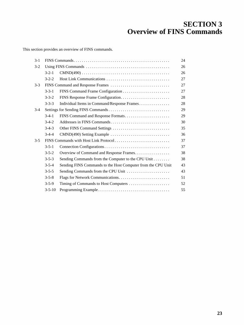
SECTION 3Overview of FINS Commands
This section provides an overview of FINS commands.
3-1 FINS Commands. . . . . . . . . . . . . . . . . . . . . . . . . . . . . . . . . . . . . . . . . . . . . . . 24
3-2 Using FINS Commands . . . . . . . . . . . . . . . . . . . . . . . . . . . . . . . . . . . . . . . . . 26
3-2-1 CMND(490) . . . . . . . . . . . . . . . . . . . . . . . . . . . . . . . . . . . . . . . . . . . 26
3-2-2 Host Link Communications . . . . . . . . . . . . . . . . . . . . . . . . . . . . . . . 27
3-3 FINS Command and Response Frames . . . . . . . . . . . . . . . . . . . . . . . . . . . . . 27
3-3-1 FINS Command Frame Configuration . . . . . . . . . . . . . . . . . . . . . . . 27
3-3-2 FINS Response Frame Configuration. . . . . . . . . . . . . . . . . . . . . . . . 28
3-3-3 Individual Items in Command/Response Frames . . . . . . . . . . . . . . . 28
3-4 Settings for Sending FINS Commands . . . . . . . . . . . . . . . . . . . . . . . . . . . . . . 29
3-4-1 FINS Command and Response Formats. . . . . . . . . . . . . . . . . . . . . . 29
3-4-2 Addresses in FINS Commands. . . . . . . . . . . . . . . . . . . . . . . . . . . . . 30
3-4-3 Other FINS Command Settings . . . . . . . . . . . . . . . . . . . . . . . . . . . . 35
3-4-4 CMND(490) Setting Example . . . . . . . . . . . . . . . . . . . . . . . . . . . . . 36
3-5 FINS Commands with Host Link Protocol . . . . . . . . . . . . . . . . . . . . . . . . . . . 37
3-5-1 Connection Configurations . . . . . . . . . . . . . . . . . . . . . . . . . . . . . . . . 37
3-5-2 Overview of Command and Response Frames. . . . . . . . . . . . . . . . . 38
3-5-3 Sending Commands from the Computer to the CPU Unit . . . . . . . . 38
3-5-4 Sending FINS Commands to the Host Computer from the CPU Unit 43
3-5-5 Sending Commands from the CPU Unit . . . . . . . . . . . . . . . . . . . . . 43
3-5-8 Flags for Network Communications. . . . . . . . . . . . . . . . . . . . . . . . . 51
3-5-9 Timing of Commands to Host Computers . . . . . . . . . . . . . . . . . . . . 52
3-5-10 Programming Example . . . . . . . . . . . . . . . . . . . . . . . . . . . . . . . . . . . 55

FINS Commands Section 3-1
3-1 FINS CommandsFINS commands form a command system for message services across differ-ent OMRON networks. They can be used for various control operations, suchas sending and receiving data, changing operating modes, executing forcedset and forced reset operations, performing file operations, and so on. FINScommands make it possible to freely communicate with Units in various net-works and on CPU Racks by simply specifying the network, node, and unit.
FINS commands have the following features:
1,2,3... 1. They are defined in the application level and do not depend on lower levels(i.e., the physical and data link levels). This allows them to be used acrossa variety of networks and CPU buses. Specifically, they can be used withEthernet, Controller Link, and Host Link networks, and between CPU Unitsand CPU Bus Units.
Note FINS commands can be sent with UDP/IP headers when usingEthernet and with Host Link command headers when using HostLink.
2. FINS commands can be used to access various kinds of devices besidesCPU Units. Devices such as CPU Units, CPU Bus Units, personal comput-ers (boards), and Inner Boards can be identified and specified by their unitaddresses.
3. FINS commands support network relay operations, so they can passthrough a network hierarchy to access devices on up to three network lev-els (including the local network).
Types of FINS Commands There are basically two kinds of FINS commands: Those addressed to CPUUnits and those addressed to CPU Bus Units. Among FINS commands forCPU Units, there are commands addressed to the various models of CPUUnit, such as the CS/CJ-series CPU Units, CV-series CPU Units, C200HX/HG/HE CPU Units, and so on. The basic code system is the same, but thedetailed specifications vary according to the CPU Unit.
Among FINS commands for CPU Bus Units, there are commands addressedto Controller Link Units, to CompoBus/D Master Units, to Ethernet Units, andso on.
CPU Bus Unit
Inner Board
CPU Unit Personal computer board
Network 1
Network 2
Network 3
24

FINS Commands Section 3-1
FINS Commands Addressed to CS/CJ-series CPU Units
CS/CJ-series CPU Units can receive FINS commands from a PC (CS/CJ,CVM1/CV, or C200HX/HG/HE(-Z) CPU Unit) or computer on another networkor from a host computer connected directly to the local network.
1,2,3... 1. A FINS command sent from a PC or computer on another network is trans-mitted to the CPU Unit from the Backplane of the CPU Rack, via a Com-munications Unit (Controller Link Unit, Ethernet Unit, etc.)
2. FINS commands sent from a host computer to a CPU Unit are sent with aHost Link header code and a terminator (as in the Host Link communica-tions mode).
The FINS commands available for CS/CJ-series CPU Units fall into the follow-ing broad categories. (Refer to the relative operation manuals for FINS com-mands addressed to other Units and Boards.)
• I/O memory area reading and writing
• Parameter area reading and writing
• Program area reading and writing
• Operating mode changes
• Machine configuration reading
• CPU Unit status reading
• Time data access
• Message reading and clearing
• Access rights acquisition and release
• Error log reading and clearing
• File operations
• Forced set/reset
PC on another network CS/CJ-series PC
CPU UnitCPU Unit
Computer
FINS command FINS command
Host computer
Communications Unit
CS1-series CPU Unit
Host computer
Serial communications (Host Link mode)
Communications Unit
CPU Unit
PC on network
FINS commandNetwork (Controller Link, Ethernet, etc.)
Computer on network
Communications Board
FINS command
25

Using FINS Commands Section 3-2
3-2 Using FINS CommandsFINS commands for CPU Units can be used by means of either CMND(490)or Host Link communications.
3-2-1 CMND(490)FINS commands can be sent to a CS/CJ-series CPU Unit by executingCMND(490) in the program of another PC (CPU Unit) on the network. Thebasic procedure is as follows:
1,2,3... 1. Store the command format of the FINS command (i.e., the command data)in an I/O memory area, such as the DM area.
2. In the same way, store the control data (number of bytes of transmissiondata, destination address, etc.) in an I/O memory area, such as the DM ar-ea.
3. Designate S (first command word), D (first response word), and C (firstcontrol word) for the CMND(490) operands, and execute the instruction.
4. When the FINS response is returned from the destination node (a CS/CJ-series CPU Unit), the data will be stored according to the response formatbeginning at the first response word.
Note FINS commands and responses are handled as binary data, and data is sentand received in binary format. (Host Link communications, however, are basi-cally in ASCII.)
CMND(490) execution
Command
Word
1 byte 1 byte
Command format data
1 byte 1 byte
Control data
Designates where to send, etc.
Communications Unit (Controller Link Unit, etc.)
CS/CJ-series CPU Unit
CS/CJ-series CPU Unit
Response frame
2 bytes 2,000 bytes max.
FINS header
2 bytes 1,998 bytes max.2 bytes
Automatically attached.
Command code
End code
Text
Word
Response format data
FINS header
Automatically attached.
Command code
Text
@CMND
S
D
C
Command frame
Res
pons
e
26

FINS Command and Response Frames Section 3-3
3-2-2 Host Link CommunicationsWith Host Link communications, a FINS command frame with a Host Linkheader and a terminator is sent from a host computer to a CS/CJ-series CPUUnit. The basic frame formats are shown below.
Note Host Link communications handle ASCII data, so data is sent and received inASCII. For that reason, FINS command and response frames must also besent and received in ASCII when they are handled using Host Link communi-cations.
Command Frame
Note A FINS command frame also consists of the destination node address, thesource node address, and other FINS command format data.
The CS/CJ-series CPU Unit that receives the command will return the follow-ing response frame to the host computer.
Response Frame
Note A FINS response frame also consists of the contents set (e.g., requested) atthe time of transmission and the FINS command response format data.
It is also possible to send a FINS command frame with a Host Link headerand terminator from a CS/CJ-series CPU Unit to a host computer connectedby Host Link System (unsolicited communications initiated by a slave).
3-3 FINS Command and Response FramesIf the data from the command code onwards is set in the words specified withS when a FINS command is sent by means of CMND(490), a FINS header willbe generated automatically and attached, and the FINS command frame willbe sent. When the FINS response frame is received, the FINS header will beautomatically removed and the response data from the command codeonwards will be stored as specified in the words specified with operand D.
When a FINS command is sent by Host Link communications, the header isattached before the FINS frame, and the FCS and terminator are attachedafter it.
3-3-1 FINS Command Frame Configuration
Host Link header FINS command frame (See note.)Host Link
FCS Host Link terminator
Host Link header FINS response frame (See note.) Host Link FCS Host Link terminator
FINS header (automatically attached for CMND(490))
Command code
Text
*Set in word specified for CMND(490) operand S onwards.
*With Host Link communications, the header, FCS, and terminator are attached before and after the frame.
27

FINS Command and Response Frames Section 3-3
3-3-2 FINS Response Frame Configuration
3-3-3 Individual Items in Command/Response FramesICFThe ICF (Information Control Field) is configured as shown in the followingdiagram.
RSVRSV (Reserved) is always 00.
GCTGCT (Gateway Count: Number of Bridges Passed Through) is always 02.
DNADestination network address. Specify within the following ranges.00: Local network01 to 7F: Remote network address (decimal: 1 to 127)
DA1Destination node address. Specify within the following ranges. 00: Internal communications in PC01 to 20: Node address in Controller Link Network (1 to 32 decimal)FF: Broadcast transmission
DA2Destination unit address. Specify within the following ranges.00: CPU UnitFE: Controller Link Unit or Ethernet Unit connected to network10 to 1F: CPU Bus UnitE1: Inner Board
SNASource network address. Specify within the following ranges.00: Local network01 to 7F: Remote network (1 to 127 decimal)
SA1Source node address. Specify within the following ranges.00: Internal communications in PC01 to 20: Node address in Controller Link Network (1 to 32 decimal)
SA2Source unit address. Specify within the following ranges.00: CPU Unit10 to 1F: CPU Bus Unit
FINS header (deleted automatically for CMND(490))
Command code
Text
*Set in word specified for CMND(490) operand D onwards.
*With Host Link communications, the header, FCS, and terminator are added before and after the frame.
End code
Bit
Always 0. Response (0: Required; 1: Not required)Data classification (0: Command; 1: Response)Bridges (0: Not used; 1: Used) Always 1.
28

Settings for Sending FINS Commands Section 3-4
SIDService ID. Used to identify the process generating the transmission. Set theSID to any number between 00 and FF
Note 1. The unit address for a CPU Bus Unit is 10 (hexadecimal) plus the unit num-ber set on the front panel of the CPU Bus Unit.
2. Refer to 3-4-2 Addresses in FINS Commands for information on unit ad-dresses and other addresses used in FINS commands.
3-4 Settings for Sending FINS Commands
Note 1. Set these as operands when executing CMND(490).
2. Do not set the gateway count when using CMND(490).
3-4-1 FINS Command and Response FormatsCommand Format As shown below, the command format basically consists of the command
code (four digits hexadecimal) and parameters (text).
Note The command code is a 2-byte code that expresses the content of the com-mand. A FINS command must begin with a 2-byte command code. If there isalso text, it is added after the command code.
Example: Command for Reading I/O Memory
Settings for sending FINS commands
Command format
Address
Network address
Unit address
Node address
Response required/not required
Communications port No. (See note 1.)
Number of retries (See note 1.)
Other
Response monitor time (See note 1.)
Gateway count (See note 2.)
Command code (See note.)4 digits hexadecimal(2 bytes)
Text (Various kinds of data)The length depends on the command code.
01 01 HexMemory area code
Beginning read address
Number of read elements
Command code Text
29

Settings for Sending FINS Commands Section 3-4
The following data would read 10 words starting from D00010.
Response Format As shown below, the response format basically consists of the command code(four digits hexadecimal), end code, and parameters (text).
Note The end code is a 2-byte code that shows the command execution result.(The first byte shows the general category, and the second byte shows thedetailed results.)
Example: Response from Reading I/O Memory
Actual response data would be as follows:
3-4-2 Addresses in FINS CommandsFINS commands are transmitted across networks and to various devices (vianetwork nodes). Designate the addresses as follows:
• Designate the device from which the command is to be sent, the networkthat the device is on, and the node through which the command is to tran-sit.
• Designate the device to which the command is to be sent, the network thedevice is on, and the node through which command is to transit.
Addresses must be provided for the network, node, and device (unit) to iden-tify them. FINS commands include these addresses (the transmission sourceand destination addresses) in the command/response frames.
01 01 Hex
Command code
First read address
000A Hex00 00 0A Hex82 Hex
Memory area code
Number of read elements
Parameters
End code (See note.)Command code4 digits hexadecimal(2 bytes)
Text (Various kinds of data)The length depends on the command code.
01 01 Hex
Command code Text
End code
End code
Read data
01 01 Hex
Command code
Text: 10 words (20 bytes) of read data.
00 00 Hex
Response code
30

Settings for Sending FINS Commands Section 3-4
Addresses for FINS Commands
Devices on the Same Network
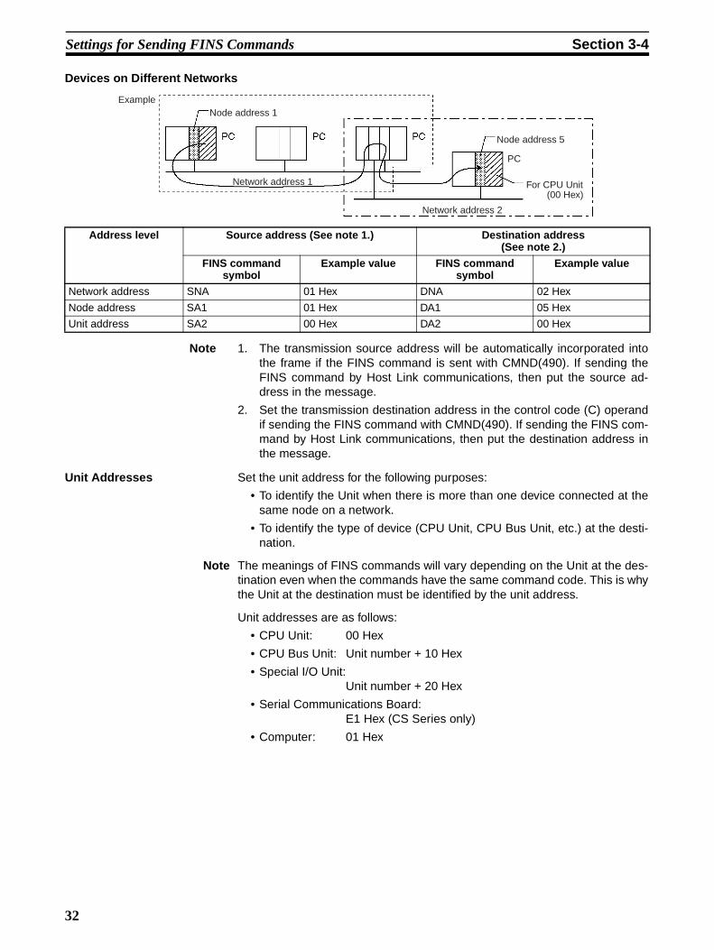
Note 1. The transmission source address will be automatically incorporated intothe frame if the FINS command is sent with CMND(490). If sending theFINS command by Host Link communications, then put the source ad-dress in the message.
2. Set the transmission destination address in the control code (C) operandif sending the FINS command with CMND(490). If sending the FINS com-mand by Host Link communications, then put the destination address inthe message.
Address Values Designation method
CMND(490) operand designation
Designation in frame when frame is created
Network address 1 to 127 (01 to 7F Hex)Local node address: 00 Hex
Yes Yes
Node address Internal Communications in PC: 00 HexFor Ethernet Unit: 01 to 7F Hex (1 to 126)For Controller Link: 01 to 20 Hex (1 to 32)
Yes Yes
Unit address �CPU Unit: 00 Hex
�CPU Bus Unit: Unit No.+ 10 Hex�Special I/O Unit: Unit No.+ 20 Hex�Inner Board: E1 Hex
�Computer: 01 Hex�Unit connected to network: FE Hex
Yes Yes
ExampleNode address 1 Node address 2 Node address 3
For CPU Unit
(00 Hex)
Address Source address (See note 1.) Destination address(See note 2.)
FINS command symbol
Example value FINS command symbol
Example value
Network address SNA 00 Hex DNA 00 Hex
Node address SA1 01 Hex DA1 03 Hex
Unit address SA2 00 Hex DA2 00 Hex
31
Settings for Sending FINS Commands Section 3-4
Devices on Different Networks
Note 1. The transmission source address will be automatically incorporated intothe frame if the FINS command is sent with CMND(490). If sending theFINS command by Host Link communications, then put the source ad-dress in the message.
2. Set the transmission destination address in the control code (C) operandif sending the FINS command with CMND(490). If sending the FINS com-mand by Host Link communications, then put the destination address inthe message.
Unit Addresses Set the unit address for the following purposes:
• To identify the Unit when there is more than one device connected at thesame node on a network.
• To identify the type of device (CPU Unit, CPU Bus Unit, etc.) at the desti-nation.
Note The meanings of FINS commands will vary depending on the Unit at the des-tination even when the commands have the same command code. This is whythe Unit at the destination must be identified by the unit address.
Unit addresses are as follows:
• CPU Unit: 00 Hex
• CPU Bus Unit: Unit number + 10 Hex
• Special I/O Unit:Unit number + 20 Hex
• Serial Communications Board:E1 Hex (CS Series only)
• Computer: 01 Hex
Address level Source address (See note 1.) Destination address(See note 2.)
FINS command symbol
Example value FINS command symbol
Example value
Network address SNA 01 Hex DNA 02 Hex
Node address SA1 01 Hex DA1 05 Hex
Unit address SA2 00 Hex DA2 00 Hex
ExampleNode address 1
Node address 5
For CPU Unit(00 Hex)
PC
Network address 1
Network address 2
32

Settings for Sending FINS Commands Section 3-4
• Communications Unit with the specified node address connected to net-work with the specified network address (Controller Link or Ethernet):
FE Hex
Note It is also possible to set the serial port (No. 1 to 4) for the destination device.(No. 0 indicates the device itself.)
Unit Addresses for Computers Connected to Serial Ports
The unit addresses for host computers connected to a CS/CJ serial port (e.g.,on a CPU Unit, Serial Communications Unit, or Serial Communications
Board) are shown in the following table.
For the SEND, RECV, and CMND instructions, the CPU Unit will add theproper unit address based on the unit address of the Unit/Board and the spec-ified serial port. It is not necessary to consider these addresses in the ladder-diagram program.
Summary of Addresses The three addresses used in FINS commands can be summarized as follows(refer to the following diagram):
Network AddressAn address that identifies the entire network. All nodes on the same networkhave the same network address.
Node AddressAn address that identifies an individual node on a network, such as a PC orhost computer.
Unit address 00 Hex Unit No. + 10 Hex E1 Hex 01 Hex
Contents Node address
Node address
Node address Node
address
Serial Communications Unit
Serial port 1Serial port 2
Serial Communications Board
Serial port 1Serial port 2
Serial port 1Serial port 2
CPU Unit
Unit/Board Serial port 1 Serial port 2
CPU Unit FC Hex FD Hex
Serial Communications Board
E4 Hex E5 Hex
Serial Communications Unit
80 Hex + 04 Hex x unit number
81 Hex + 04 Hex x unit number
33

Settings for Sending FINS Commands Section 3-4
Unit AddressFor a PC, an address that identifies the specific Unit that is participating in thecommunication in the PC. For a host computer, an address that identifies thespecific application that is participating in the communication in the computer.
PCNode address: 5
Ethernet networkNetwork address 1
PCNode address: 8
Node address: 8
PCNode address: 2
PCNode address: 3
ComputerNode address: 1
ComputerNode address: 11
PC
Node ad-dress: 7
Controller Link UnitUnit address: 12 Hex
Ethernet UnitUnit address: 15 Hex
Controller Link NetworkNetwork address 2
Communications Unit (Controller Link Unit)Unit address: 12 Hex
CPU UnitUnit address: 0 Hex
34

Settings for Sending FINS Commands Section 3-4
3-4-3 Other FINS Command Settings
Aside from the addresses, the following data must be set.
Note Unit address are fixed for Units and Boards, as well as for serial ports. For theSEND(090), RECV(098), and CMND(490) instructions, the CPU Unit will addthe proper unit address based on the unit address of the Unit/Board and thespecified serial port. It is not necessary to consider these addresses in theladder-diagram program.Serial Port 1: 80 Hex + 04 Hex x unit number for Serial Communications Units, E4 Hex forSerial Communications Boards, and FC Hex for the peripheral port on theCPU Unit.Serial Port 2: 81 Hex + 04 Hex x unit number for Serial Communications Units, E5 Hex forSerial Communications Boards, and FD Hex for the RS-232C port on the CPUUnit.
Setting Content Values Designation method
CMND(490) operand
designation
Designation in frame when
frame is created
Number of retries Number of times to retry sending the command.
0 to F Hex (0 to 15 times) Yes No
Port No. Logical communications port. CS/CJ-series CPU Units have 8 com-munications ports, so 8 communi-cations commands can be executed simultaneously. To exe-cute 9 or more commands, simul-taneously, it is necessary to set up exclusive control.
0 to 7 Hex Yes No
Serial port No. Specifies the number of the serial port of the Unit with Host Link capabilities.
0: Unit/Board
1: Serial port 1 for Serial Communications Board/ Unit or Peripheral port for CPU Unit
2: Serial port 2 for Serial Communications Board/ Unit or RS-232C port for CPU Unit
Yes No
Response moni-tor time
Monitors the time it takes to return a response. If a response is not returned within the designated time, a response timeout is gener-ated.
0001 to FFFF Hex (0.1 to 6,553.5 seconds)
Yes No
Response required/ not required (ICF bit 0)
Designates whether or not a response is required.
0 or 1 (bit) Yes Yes
Gateway count Designates the number of net-works that can be accessed.
Always 02 Hex (2 times). No Yes
35

Settings for Sending FINS Commands Section 3-4
3-4-4 CMND(490) Setting ExampleThe designated number of bytes of FINS command data from the first com-mand word designated by operand S is sent to the designated unit addressvia the node address on the network address designated by operand C, andthe response is stored for the number of bytes of data received starting fromD.
In this example, a command (MEMORY AREA READ: 0101 Hex) for readingD00010 to D00019 of the PC at node 02 is sent using CMND(490).
D00010: Memory area code (82 Hex), address 000A00Number of elements read: 10 = 0A Hex
S: First command word
D: First response word
C: First control word
S: First command word C: First control word
Command code
Beginning read addressMemory area code
Beginning read address
Number of elements read
D: First response word
Control code
End code
Read data
Read data
Number of command data bytes
Number of response data bytes
Destination network address
Destination unit addressDestination node address
Communications port numberNumber of retries
Response required/not required
Response monitor time
Serial port No.
0000
0000
0002
0300
0000
0101
0082
0A 00
0A00
0101
0800
1800
36

FINS Commands with Host Link Protocol Section 3-5
3-5 FINS Commands with Host Link ProtocolFINS commands can be sent and received using the Host Link protocolbetween interconnected host computers and PCs.
3-5-1 Connection ConfigurationsOne of the following two methods can be used to send and receive FINS com-mands using the Host Link protocol.
Sending from a Computer to a CPU Unit
Note The host computer can be connected to the peripheral port or RS-232C porton the CPU Unit or to a serial ports on a Serial Communications Unit/Board.The Host Link protocol must be used regardless of the point of connection.
CPU Unit Directly Connected to Host Computer
CPU Units on a Network
Sending from a CPU Unit to a Computer (Slave Initiation)
Note The host computer can be connected to the peripheral port or RS-232C porton the CPU Unit or to a serial ports on a Serial Communications Unit/Board.The Host Link protocol must be used regardless of the point of connection.
CPU Unit Directly Connected to Host Computer
Host Link
FINS command
CPU Unit
Host Link
FINS command
CPU Unit CPU Unit
Network (Controller Link, Ethernet, etc.)
Host Link
FINS command
CPU Unit
SEND(090)
RECV(098)
CMND(490)
37

FINS Commands with Host Link Protocol Section 3-5
CPU Unit Directly Connected to Host Computer on a Network
Note Host Link communications handle ASCII data, so data is sent and received inASCII. Hexadecimal values in FINS command and response frames must,therefore, also be sent and received in ASCII when they are handled usingHost Link communications.
3-5-2 Overview of Command and Response FramesWhen FINS commands and responses are sent or received using Host Linkcommunications, the frame must be preceded by a Host Link header and fol-lowed by a Host Link FCS and terminator as shown below.
Command Frame Use the following format to send FINS command frames.
Note A FINS command frame also consists of the response wait time, the destina-tion node address, the source node address, and other FINS command for-mat data.
Response Frame The CS/CJ-series CPU Unit that receives the command will return the follow-ing response frame to the host computer.
Note A FINS response frame also consists of the contents set at the time of trans-mission and the FINS command response format data.
3-5-3 Sending Commands from the Computer to the CPU Unit
Command Format from Host ComputerUse the following command format to send FINS commands from the hostcomputer to the CPU Unit.
Note The length of the command must be not more than 1,114 characters. FINScommands cannot be partitioned into separate frames for sending.
Host Link
FINS command
CPU Unit
SEND(090)
RECV(098)
CMND(490)
Network (Controller Link, Ethernet, etc.)
CPU Unit
Host Link header FINS command frame (See note.)Host Link
FCS Host Link terminator
Host Link header FINS response frame (See note.) Host Link FCS Host Link terminator
38

FINS Commands with Host Link Protocol Section 3-5
Sending Commands to a CPU Unit Directly Connected to the Host Computer
Note The following format is also applicable for a host computer connected to aSerial Communications Board or a Serial Communications Unit.
Sending Commands to a CPU Unit on a Network
Note The following format can also be used to send FINS commands to a CPU Unitconnected to the host computer.
Host Link Settings @The @ symbol must be attached to the beginning of the command.
Unit NumberThe unit number set is that of the destination CPU Unit connected to the hostcomputer. When the host computer is connected to a CPU Unit, the unit num-ber is designated in the PC Setup.
When the host computer is connected to a Serial Communications Board or aSerial Communications Unit, the unit number is the designated in the Setupfor the Board or Unit.
Header CodeThe header code distinguishes between different types of commands. Set“FA” (ASCII: 46, 41) when using FINS commands.
Response Wait TimeThe response wait time sets the time from when the CPU Unit receives acommand block until it starts to return a response. It can be set from 0 to F inhexadecimal, in units of 10 ms.
Example:
If F(15) is set, the response will begin to be returned 150 ms (15 � 10 ms)after the command block was received.
ICF (Information Control Field)Specifies whether or not there are network relays. Set “80” (ASCII: 38,30)
Unit No. Header code Response
wait time
FINS command code Text (1,080 characters = 540 bytes max.)
Terminator
ICF DA2 SA2 SID
FCS
x
*
x x x x
x xx xx x
Unit No. Header code Response
wait time
FINS command code Text (1,080 characters = 540 bytes max.)
Terminator
ICF RSV GCT DNA DA1
DA2 SNA SA1 SA2 SID
FCS
x x x x x x x
x x x x x x x x
x x *
39

FINS Commands with Host Link Protocol Section 3-5
when sending an FINS command to a CPU Unit on a network. Set “00”(ASCII: 30,30) when sending to a CPU Unit connected directly to the hostcomputer.
RSV (Reserved)Set “00” (ASCII: 30,30). Setting RSV is required only when sending to a CPUUnit on a network.
GCT (Gateway Count)This is the number of networks through which the transmission can berelayed. Set “02” (ASCII: 30,32). Setting GCT is required only when sendingto a CPU Unit on a network.
DNA, DA1, DA2Set the destination network, node, and unit addresses.
DNA (Destination Network Address)
Set between 00 and 7F Hex (0 and 127 decimal). Setting DNA is requiredonly when sending to a CPU Unit on a network.
DA1 (Destination Node Address)
Set within the following ranges. Setting DA1 is required only when sendingto a CPU Unit on a network.
Ethernet Unit: 01 to 7E Hex (1 to 126 decimal)
Controller Link Unit: 01 to 20 Hex (1 to 32 decimal)
SYSMAC NET: 01 to 7E Hex (1 to 126 decimal)
SYSMAC LINK: 01 to 3E Hex (1 to 62 decimal)
DA2 (Destination Unit Address)
Refer to 3-4-2 Addresses in FINS Commands for details on unit addresses.
In Host Link mode, it is assumed that the destination unit is the CPU Unit,so set “00” (ASCII: 30, 30).
SNA (Source Network Address), SA1 (Source Node Address)Set the source network and node addresses. Set both to “00” (ASCII: 30, 30)regardless of whether or not there is a network relay.
Setting SNA and SN1 is required only when sending to a CPU Unit on a net-work.
SA2 (Source Unit Address)Set the unit address of the Unit physically connected to the host computer.The setting changes depending on the connected Unit.
When connected to the CPU Unit, Serial Communications Board, or a SerialCommunications Unit, set “00” to indicate the CPU Unit (ASCII: 30, 30).
SID (Source ID)The SID is used as a counter when resending. It should normally be set to“00” (ASCII: 30, 30).
Command Code, TextSet the command code and text according to the FINS command andresponse formats.
FCS (Frame Check Sequence)Set a 2-character FCS. Refer to FCS Calculations under 2-2 Command/Response Formats for the FCS calculation method.
TerminatorThe terminator is a required delimiter at the end of a command. Set the termi-nator to *CR (ASCII: 2A, 0D).
40

FINS Commands with Host Link Protocol Section 3-5
Response Format from a CPU UnitThe following response format is used to return responses from the CPU Unitto the host computer.
Note The length of the response must be not more than 1,115 characters. Of this,the response data without the response code is 1,076 characters (538 bytes).
Responses from a CPU Unit Directly Connected to the Host Computer
Responses from a CPU Unit on a Network
Host Link Settings @The @ symbol must be attached to the beginning of the response.
Unit Number and Header CodeThe same unit number and header code specified in the FINS command thatwas received will be returned.
ICF (Information Control Field)For a CPU Unit on a network, “C0” (ASCII: 43, 30) will be returned. For a CPUUnit connected directly to the host computer, “40” (ASCII: 34,30) will bereturned.
RSV (Reserved)This section is reserved for the system. Set “00” (ASCII: 30,30).
GCT (Gateway Count)The same GCT that was specified in the command that was received will bereturned. Setting GCT is required in the response format only from a CPUUnit on a network.
DNA (Destination Network Address), DA1 (Destination Node Address),DA2 (Destination Unit Address)The same contents specified for SNA, SA1, and SA2 in the command thatwas received will be returned.
Unit No. Header code
FINS command code Data (1,076 characters = 538 bytes)
TerminatorFINS response code
ICF DA2 SA2 SID
FCS
x x x x
x x x x x x x x x x *
Unit No. Header code
FINS command code
Data (1,076 characters = 538 bytes))
Terminator
FINS response code
ICF RSV GCT DNA DA1
DA2 SNA SA1 SA2 SID
FCS
x x
x x x x x x x x x x x x x x x x
x x *
41

FINS Commands with Host Link Protocol Section 3-5
Setting DNA and DA1 is required for response formats only from a CPU Uniton a network.
SNA (Source Network Address), SA1 (Source Node Address), SA2(Source Unit Address)The same contents specified for DNA, DA1, and DA2 in the command thatwas received will be returned.
Setting SNA and SN1 is required for response formats only from a CPU Uniton a network.
SID (Source ID)The SID that was specified in the command that was received will bereturned.
Command Code, Response Code, TextThe command code, response code, and text corresponding to the FINS com-mand and response formats will be returned.
FCS (Frame Check Sequence)A 2-character FCS will be returned. Refer to FCS Calculations under 2-2Command/Response Formats for the FCS calculation method.
TerminatorThe terminator is a required delimiter at the end of a command. The termina-tor �CR (ASCII: 2A, 0D) will be returned.
Example: FINS Command Settings for Sending to CPU Unit on a NetworkWith Host Link communications, FINS command transmissions and recep-tions are handled in ASCII, so hexadecimal values in FINS command framesmust be sent as ASCII. For example, the hexadecimal value “0” would be “30Hex” in ASCII, and the hexadecimal value “A” would be “41 Hex” in ASCII.
The destination network address, node address, and unit number address areexplained using the following network as an example.
Sending a Command from a Host Computer to PC (A)The following addresses are specified to the CPU Unit at network address 5,node address 3:
Destination network address (DNA): 05 (30, 35)Destination node address (DA1): 03 (30, 33)Destination unit address (DA2): 00 (30, 30)(Command addressed to CPU Unit)
Sending a Command from a Host Computer to PC (B)The following addresses are specified to the CPU Unit at network address 10,node address 12:
Destination network address (DNA): 0A (30, 41)Destination node address (DA1): 0C (30, 43)Destination unit address (DA2): 00 (30, 30)(Command addressed to CPU Unit)
Host computer
Host Link
Controller Link, network address 5
Ethernet UnitNode 10
Ethernet network, network address 10
Controller Link UnitNode 3
Ethernet UnitNode 12
PC (B)PC (A)
42

FINS Commands with Host Link Protocol Section 3-5
3-5-4 Sending FINS Commands to the Host Computer from the CPU Unit
With normal Host Link communications, FINS commands are sent from thehost computer to the CPU Unit. Commands can also be sent, however, fromthe CPU Unit to the host computer. Any FINS command can be sent to thehost computer using SEND(090), which sends CPU Unit data to the hostcomputer, RECV(098), which receives data from the host computer, orCMND(490).
Slave-initiated communications allows the host computer to be notified (unso-licited communications) when an error is generated, for example, on a produc-tion line controlled by a CPU Unit. Since the host computer no longer needs toregularly communicate with the CPU Unit, the load on the host computer isreduced.
When an Ethernet Unit or Controller Link Unit are mounted to the Backplaneof the CPU Unit, commands can be sent to the host computer from a CPUUnit on a network on another level (up to three network levels).
Note In principle, send commands to the host computer only when one host com-puter is connected to one CPU Unit. If more than one CPU Unit is connectedto the host computer, the commands may collide with each other and preventnormal communications. Create a program that will exclusively control com-mands that are being sent to a host computer to which multiple CPU Units areconnected.
Considerations when Sending Commands from a CPU UnitConsider the following items when using instructions (SEND(090),RECV(098), and CMND (490)) to send commands from the CPU Unit.
1,2,3... 1. SEND(090), RECV(098), and CMND (490) executed by the CPU Unit areconverted to the same format for FINS commands that are sent to CPUUnits on networks.
2. A program must be created to process the commands received by the hostcomputer.
3. When instructions (SEND(090), RECV(098), and CMND (490)) are exe-cuted in a CPU Unit, some of the control data settings will be different. Re-fer to the relevant instruction specifications.
3-5-5 Sending Commands from the CPU UnitWhen controls are being implemented by sending commands from the localCPU Unit or another CPU Unit on a network to a host computer, three instruc-tions can be used in the user program: SEND(090), RECV(098), andCMND(490).
Send(090) Memory area data can be sent from the CPU Unit to the host computer byusing SEND(090).
Command Format Received by the Host ComputerThe FINS command transmitted to the host computer when SEND(090) isexecuted is MEMORY AREA WRITE (command code 0102). The commandformat received by the host computer is as shown in the following diagram.Refer to MEMORY AREA WRITE: 0102 in Section 5 FINS Commands fordetails.
43
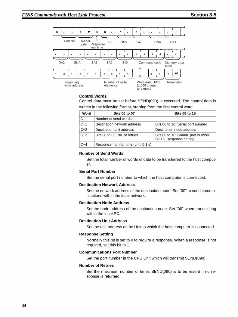
FINS Commands with Host Link Protocol Section 3-5
Control WordsControl data must be set before SEND(090) is executed. The control data is
written in the following format, starting from the first control word.
Number of Send Words
Set the total number of words of data to be transferred to the host comput-er.
Serial Port Number
Set the serial port number to which the host computer is connected.
Destination Network Address
Set the network address of the destination node. Set “00” to send commu-nications within the local network.
Destination Node Address
Set the node address of the destination node. Set “00” when transmittingwithin the local PC.
Destination Unit Address
Set the unit address of the Unit to which the host computer is connected.
Response Setting
Normally this bit is set to 0 to require a response. When a response is notrequired, set this bit to 1.
Communications Port Number
Set the port number in the CPU Unit which will transmit SEND(090).
Number of Retries
Set the maximum number of times SEND(090) is to be resent if no re-sponse is returned.
Unit No. Header code Response
wait time
ICF RSV GCT DNA DA1
DA2 SNA SA1 SA2 SID Command code Memory area code
Beginning write address
Number of write elements
Write data (1,068 characters max.)
FCS Terminator
x x x x x x x x x
x xx xx xx xx xx x
x xx xx xx xx x x x *
Word Bits 00 to 07 Bits 08 to 15
C Number of send words
C+1 Destination network address Bits 08 to 10: Serial port number
C+2 Destination unit address Destination node address
C+3 Bits 00 to 03: No. of retries Bits 08 to 10: Comm. port numberBit 15: Response setting
C+4 Response monitor time (unit: 0.1 s)
44

FINS Commands with Host Link Protocol Section 3-5
Response Monitor Time
If the Response Setting is set to require a response, set the response mon-itor time.
Control Word Settings
The setting range for each item is shown on the following table.
Note To execute SEND(090) normally, programming needs to be written to processthe data received by the host computer and return the proper response.
RECV(098) By using RECV(098), data from the host computer can be written to a mem-ory area in the CPU Unit.
Command Format Received by the Host ComputerThe FINS command transmitted to the host computer when RECV(098) isexecuted is MEMORY AREA READ (command code 0101). The commandformat received by the host computer is shown in the following diagram.
Refer to MEMORY AREA READ: 0101 in Section 5 FINS Commands fordetails
Item Setting
Number of send words 0001 to 010B (1 to 267 words)
Serial port number 00: CPU Unit/ Inner Board/CPU Bus Unit01: Port 102: Port 2
Destination network address
00: Local network
01 to 7F:Network address (1 to 127)
Destination node address 00: Internal communications in PC
01 to 7F:Node address (1 to 126) for Ethernet Unit
01 to 20:Node address (1 to 32) for Controller Link
Destination unit address I0 to 1F: Host Link Unit (Unit No. 0 to 15)
Response setting 0: Required1: Not required
Communications port number
0 to 7 (0 to 7)
Number of retries 0 to F (0 to 15)
Response monitor time 0000: Default
0001 to FFFF: 0.1 to 6,553.5 s (unit 0.1 s)
Unit No. Header code Response
wait time
ICF RSV GCT DNA DA1
DA2 SNA SA1 SA2 SID Command code Memory area code
Beginning read address
Number of read elements
FCS Terminator
x x x xx xxxx
x x x x x x x x x x x x
x x x x x x x x x x x x *
45

FINS Commands with Host Link Protocol Section 3-5
Control WordsControl data must be set before RECV(098) is executed. The control data is
written in the following format, starting from the first control word.
Number of Read Words
Set the total number of words of data to be read from the host computer.
Serial Port Number
Set the serial port number to which the host computer is connected.
Destination Network Address
Set the network address of the destination node (i.e., the computer). Set“00” to send communications within the local network.
Destination Node Address
Set the node address of the destination node (i.e., the computer). Set “00”when transmitting within the local PC.
Destination Unit Address
Set the unit address of the Unit to which the host computer is connected.
Communications Port Number
Set the port number in the CPU Unit which will transmit RECV(098).
Number of Retries
Set the maximum number of times RECV(098) is to be resent if no re-sponse is returned.
Response Monitor Time
Set the time to wait for a response
Control Word Settings
The setting range for each item is shown on the following table.
Word Bits 00 to 07 Bits 08 to 15
C Number of read words
C+1 Destination network address Bits 08 to 10: Serial port number
C+2 Destination unit address Destination node address
C+3 Bits 00 to 03: No. of retries Bits 08 to 10: Comm. port number
C+4 Response monitor time (unit: 0.1 s)
Item Setting
Number of read words 0001 to 010D (1 to 269 words)
Serial port number 00: CPU Unit, Inner Board, CPU Bus Unit01: Port 102: Port 2
Destination network address
00: Local network01 to 7F:Network address (1 to 127)
Destination node address 00: Internal communications in PC01 to 7E:Node address (1 to 126) for Ethernet Unit01 to 20:Node address (1 to 32) for Controller Link
Destination unit address 10 to 1F: Host Link Unit (Unit No. 0 to 15)
Response required/not required
0: Response required
1: Response not required
Communications port number
0 to 7 (0 to 7)
46

FINS Commands with Host Link Protocol Section 3-5
Note To execute RECV(098) normally, programming needs to be written to processthe command received by the host computer and return the proper data.
CMND(490) By using CMND(490), controls can be implemented by sending FINS com-mands to the host computer.
Command Format Received by the Host ComputerCMND(490) can be used to send any FINS command to the host computerThe command format received by the host computer is shown in the followingdiagram.
Control WordsControl data must be set before CMND(490) is executed. The control data is
written in the following format, starting from the first control word.
Number of Bytes of Command Data
Set the number of bytes of command data (including the command code)that are stored from the first command word
Number of Bytes of Response Data
Set the number of bytes of response data (including command code andend code) that are stored from the first response word.
Serial Port Number
Set the serial port number to which the host computer is connected.
Destination Network Address
Set the network address of the destination node (i.e., the computer). Set“00” to send communications within the local network.
Number of retries 0 to F (0 to 15)
Response monitor time 0000: Default0001 to FFFF: 0.1 to 6,553.5 s (unit 0.1 s)
Item Setting
Unit No. Header code Response
wait time
ICF RSV GCT DNA DA1
DA2 SNA SA1 SA2 SID Command code Data (1,080 characters max.)
FCS Terminator
x x x xxxx
x x x x x x x x x x x x x x
x x *
x x
Word Bits 00 to 07 Bits 08 to 15
C Number of bytes of command data
C+1 Number of bytes of response data
C+2 Destination network address Bits 08 to 10: Serial port number
C+3 Destination unit address Destination node address
C+4 Bits 00 to 03: No. of retries Bits 08 to 10: Comm. port numberBits 15: Response setting
C+5 Response monitor time
47

FINS Commands with Host Link Protocol Section 3-5
Destination Node Address
Set the node address of the destination node (i.e., the computer). Set “00”when transmitting within the local PC.
Destination Unit Address
Set the unit address of the Unit to which the host computer is connected.
Response Setting
Normally this bit is set to 0 to require a response. When a response is notrequired, set this bit to 1.
Communications Port Number
Set the port number in the CPU Unit which will transmit CMND(490).
Number of Retries
Set the maximum number of times CMND(490) is to be resent if no re-sponse is returned.
Response Monitor Time
If the Response Setting is set to require a response, set the response mon-itor time.
Note If response data longer than that set in the Number of Bytes of ResponseData is returned, all extra response data will not be stored. If response datashorter than that set in the Number of Bytes of Response Data is returned,the response data will be stored, and the remaining area will stay at its previ-ous values.
Control Word Settings
The setting range for each item is shown on the following table.
Note To execute CMND(490) normally, programming needs to be written to processthe command received by the host computer and return the proper response.
Item Setting
Number of bytes of com-mand data
0002 to 021E (2 to 542 bytes)
Number of bytes of response data
0002 to 021E (2 to 542 bytes)
Serial port number 00: CPU Unit, Inner Board, CPU Bus Unit01: Port 102: Port 2
Destination network address
00: Local network
01 to 7F:Network address (1 to 127)
Destination node address 00: Internal communications in PC
01 to 7E:Node address (1 to 126) for Ethernet Unit
01 to 20:Node address (1 to 32) for Controller Link
Destination unit address 10 to 1F: Host Link Unit (Unit No. 0 to 15)
Response setting 0: Required1: Not required
Communications port number
0 to 7 (0 to 7)
Number of retries 0 to F (0 to 15)
Response monitor time 0000: Default (2 s)
0001 to FFFF: 0.1 to 6,553.5 s (unit: 0.1 s)
48

FINS Commands with Host Link Protocol Section 3-5
3-5-6 Command Format Received by the Host ComputerFINS commands sent to the host computer are received at the host computerin the format shown below.
Unit NumberThe unit number of the host link port connected to the host computer is set.
Header CodeThe header code in FINS commands sent to the host computer is always setto “OF” (ASCII: 4F, 46).
Response Wait TimeThe response wait time in FINS commands sent to the host computer is fixedat to “0” (ASCII: 4F, 46).
ICF (Information Control Field)Specifies whether or not a response is required.
Response required: “80” (ASCII: 38,30)Response not required: “81” (ASCII: 38,31)
RSV (Reserved)Always set to “00” (ASCII: 30,30) in commands sent to the host computer.
GCT (Gateway Count)The number of networks through which the command is relayed subtractedfrom 2 is set.
Number of networks = 0: “02” (ASCII: 30,32)Number of networks = 1: “01” (ASCII: 30,32)Number of networks = 2: “00” (ASCII: 30,32)
DNA, DA1, DA2The addresses for the Host LInk Unit connected to the host computer are set.
DNA (Destination Network Address)
The network address (00 to 7F Hex) of the CPU Unit is set in hexadecimal.
DA1 (Destination Node Address)
The node address (01 to 7E Hex) of the CPU Unit is set in hexadecimal.
DA2 (Destination Unit Address)
The unit address of the Host Link port is set.
SNA, SA1, SA2The addresses for the source node (e.g., PC, FA computer) are set.
SNA (Source Network Address)
The network address (00 to 7F Hex) of the source is set in hexadecimal.
Unit No. Header code Response
wait time
ICF RSV GCT DNA DA1
DA2 SNA SA1 SA2 SID Command code Text (1,080 characters max.)
FCS Terminator
x x x xxxx
x x x x x x x x x x x x x x
x x *
x x
49

FINS Commands with Host Link Protocol Section 3-5
SA1 (Source Node Address)
The node address (01 to 7E Hex) of the source is set in hexadecimal.
SA2 (Source Unit Address)
The unit address of the source is set.
SID (Source ID)
Automatically set by the CPU Unit using SEND(090), RECV(098), andCMND(490).
3-5-7 Response Format Returned by the Host ComputerResponses to FINS commands received by the host computer are returned inthe format shown below.
ICF (Information Control Field)“C0” (ASCII: 43, 30) will be returned.
RSV (Reserved)“00” (ASCII: 30,30) is returned.
GCT (Gateway Count)“02” (ASCII: 30,32) is returned.
DNA (Destination Network Address), DA1 (Destination Node Address),DA2 (Destination Unit Address)The same contents specified for SNA, SA1, and SA2 in the command thatwas received will be returned.
SNA (Source Network Address), SA1 (Source Node Address), SA2(Source Unit Address)The same contents specified for DNA, DA1, and DA2 in the command thatwas received will be returned.
SID (Source ID)The SID that was specified in the command that was received will bereturned.
Command CodeThe command code that was specified in the command that was received willbe returned.
Note The length of the response cannot exceed 1,115 characters. Createresponses so that the response data without the response code is less than1,076 characters (538 bytes).
Unit No. Header code
FINS command code
Data (1,076 characters)
Terminator
FINS response code
ICF RSV GCT DNA DA1
DA2 SNA SA1 SA2 SID
FCS
x x
x x x x x x x x x x x x x x x x
x x *
x x
x x x xx x
50

FINS Commands with Host Link Protocol Section 3-5
3-5-8 Flags for Network CommunicationsThis section describes the flags in the Auxiliary Area that are used when exe-cuting SEND(090), RECV(098), and CMND(490).
Communications Port Enabled Flags
A Communications Port Enabled Flag turns ON when SEND(090),RECV(098), and CMND(490) can be executed. The Flag will turn OFF duringexecution of these commands and turn ON again when the command execu-tion is completed. When creating the ladder diagram, use these Flags as input
conditions when executing these instructions.
Communications Port Error Flags
A Communications Port Error Flag will turn ON in the following cases.
• When an error is generated during execution of SEND(090), RECV(098),or CMND(490).
• When an error response or retry error has been generated for the port.
These Flags will turn OFF when the corresponding Communications PortEnabled Flag is turned OFF at the start of operation or at the start of execut-
ing the SEND(090), RECV(098), or CMND(490).
Communications Port Completion Codes
The Communication Port Completion Code words will contain the FINS endcode after SEND(090), RECV(098), or CMND(490) has been executed.
If the Communications Port Enabled Flag turns OFF when operation is startedor SEND(090), RECV(098), or CMND(490) are executed, the contents of
these words will be cleared.
Word Bit Content
A202 08 to 15 Reserved
07 Communications Port Enabled Flag, Port No. 7
06 Communications Port Enabled Flag, Port No. 6
05 Communications Port Enabled Flag, Port No. 5
04 Communications Port Enabled Flag, Port No. 4
03 Communications Port Enabled Flag, Port No. 3
02 Communications Port Enabled Flag, Port No. 2
01 Communications Port Enabled Flag, Port No. 1
00 Communications Port Enabled Flag, Port No. 0
Word Bit Content
A219 15 to 08 Reserved
07 Communications Port Error Flag, Port No. 7
06 Communications Port Error Flag, Port No. 6
05 Communications Port Error Flag, Port No. 5
04 Communications Port Error Flag, Port No. 4
03 Communications Port Error Flag, Port No. 3
02 Communications Port Error Flag, Port No. 2
01 Communications Port Error Flag, Port No. 1
00 Communications Port Error Flag, Port No. 0
Word Content
A203 Communications Port Completion Code, Port No. 0
A204 Communications Port Completion Code, Port No. 1
A205 Communications Port Completion Code, Port No. 2
A206 Communications Port Completion Code, Port No. 3
A207 Communications Port Completion Code, Port No. 4
A208 Communications Port Completion Code, Port No. 5
51

FINS Commands with Host Link Protocol Section 3-5
Flag Transitions
3-5-9 Timing of Commands to Host ComputersCommands sent to a host computer are transmitted with the timing shownbelow.
Data Received from Host Computer
Command transmission to the host computer can commence even when theport is receiving a command from the host computer (1). The transmission ofa response to the command from the host computer is postponed until thetransmission of the command to the host computer is completed (2).
When a response is not required from the host computer, the Communica-tions Port Enabled Flag will turn ON when the command to the host computerhas passed from the CPU Unit to the port.
A209 Communications Port Completion Code, Port No. 6
A210 Communications Port Completion Code, Port No. 7
A211 to A218 Reserved
Word Content
Communications Port Enabled Flag
Network communications instructions (SEND(090)/RECV(098)/CMND(490))
Communications Port Error Flag
Communications end code
Command 1 being executed
Command 2 being executed
Command 3 being executed
End of previous processing
Normal end
Normal end
(No unit corresponding to unit address)
Response Required
Host computer Command
ResponseSerial Communications Board/Unit
Communications Port Enabled Flag
Command acknowledged Command completed
No Response Required
Host computer
Serial Communications Board/Unit
Command
Command Response
Communications Port Enabled Flag
Command acknowledged Command completed
(1)
(2)
(1)
(2)
Command
Response
52

FINS Commands with Host Link Protocol Section 3-5
Host Computer Receiving Data
At (1) in the diagram, the response to a command sent from the host com-puter is being transmitted from the port. In this case, the command transmis-sion to the host computer is postponed until the response transmission iscompleted (2).
When a response is not required from the host computer, the Communica-tions Port Enabled Flag will turn ON when the command to the host computerhas passed from the CPU Unit to the port.
Response Wait Time
When response wait time has been set in the command format from the hostcomputer, commands to the host computer will not be transmitted until theresponse time has elapsed (1). Transmission of responses to commands from
Response Required
Host computerCommand Response
ResponseSerial Communications Board/Unit
Communications Port Enabled Flag
Command acknowledged Command completed
No Response Required
Host computer
Serial Communications Board/Unit
Command
Response
Communications Port Enabled Flag
Command acknowledged Command completed
(1) (2)
(1) (2)
Command
Command
Response Required
Host computer Command
ResponseSerial Communications Board/Unit
Communications Port Enabled Flag
Command acknowledged Command completed
No Response Required
Host computer
Serial Communications Board/Unit
Command
Response
Communications Port Enabled Flag
Command acknowledged Command completed
Response wait time
Response wait time
(1)
(2)
(1)
(2)
Command
Response
Command
53

FINS Commands with Host Link Protocol Section 3-5
the host computer will be postponed until the command transmission to thehost computer has been completed.
When a response is not required from the host computer, the Communica-tions Port Enabled Flag will turn ON when the command to the host computerhas passed from the CPU Unit to the port.
54

FINS Commands with Host Link Protocol Section 3-5
3-5-10 Programming Example
1,2,3... 1. When the SEND(090)/RECV(098) Enabled Flag is ON, and the executioncondition CIO 000000 is ON, execution of the instructions for networktransmissions are started. CIO 012800 will remain ON from whenSEND(090) is started until execution has been completed.
Main execution condition
(070)XFER #000A D02000 D05030
012801
012802
000200
(011) KEEP 012800
A20204
000000
(021)@MOV #000A D00000
(021) @MOV #0001 D00001
(021)@MOV #0300 D00002(021) @MOV #0405 D00003
(021) @MOV #0000 D00004
(070) @XFER #000A 0100 D00010
(090)@SENDD00010 D00020 D00000
012800
(013) DIFU 012801
012800
A20204
012800
A21904
012803
012802 (011)
KEEP 012802
A20204
000001
(021) @MOV #000A D00100
(021)@MOV #0001 D00101
(021) @MOV #0400 D00102 (021)@MOV #0405 D00103
(021) @MOV #0030 D00104
(098)@RECVD01000 D02000 D00100
012802
000201
(013) DIFU 012801
012802
A20204
012802
A21904
A21904
012803
012802
END
(1)
(2)
(3)
(4)
(5)
(6)
(7)
(8)
(9)
(10)
(11)
(12)
55

FINS Commands with Host Link Protocol Section 3-5
2. Set the control data.
3. Transmit Data Stored
Stores 10 words of data starting from CIO 0100 to D00010 and later.
4. Execute SEND(090).
5. When the instruction for network communications has been completed(A20204: ON), CIO 012801 will turn ON, and the instruction for sending onthe network is completed.
6. Turns ON when an error is generated during execution of network commu-nications.
7. When the Communications Port Enabled Flag is ON and execution condi-tion CIO 000001 is ON, execution of the instruction for receiving via thenetwork (RECV(098)) is started.
8. Set the control data.
9. Execute RECV(098).
10. When the execution of network communications instructions has beencompleted (A20204: ON), CIO 012803 will turn ON, and the instruction forreceiving via the network is completed.
11. Turns ON when an error is generated during execution of network commu-nications.
12. Reception data processing
When there is no reception error, 10 words of data (starting from D02000)are stored from D05030 onwards.
Programming Example for Host Computer Side (BASIC): Send10 ’***************************************20 ’**** CS1W-SCU21 Serial Communications Unit ****30 ’**** Command to Host Computer (SEND(090)) ****40 ’**** Sample Send Program ****50 ’***************************************60 ’70 ’============ Initial Settings ============80 CLOSE 190 ON ERROR GOTO *EROPE100 DIM CHDATA$ (300) :’ Data array declaration110 OPEN ”COM:E73” AS #1 :’ Opens port.120 ’130 ’============ Main Process ============140 INPUT #1, COMMAND$ :’ Receives data from PC (line).
Number of send words: 10
Serial port 1 (peripheral port)Destination network address $00 (B network)
Destination node address $00 (B node)Destination unit address $00 (CPU Unit)Response required, Communications port No. 4Number of retries: 5
Response monitor time: 2 s ($0000: Default)
Number of receive words: 10Serial port 2Source network address $01Source node address $04
Source unit address $01 (Inner Board)Response required, Communications port No. 4
Number of retries: 5
Response monitor time: 4.8 s ($0030)
56

FINS Commands with Host Link Protocol Section 3-5
150 T$=LEFT$ (COMMAND$, LEN (COMMAND$) -3) :’ Checks FCS.160 GOSUB *FCS170 IF FCS$<>MID$ (COMMAND$, LEN (COMMAND$) -2, 2) THEN ENDCODE$=”1004”:GOTO *RESPONSE180 CMNDCODE$=MID$ (COMMAND$, 27, 4) :’ Checks command code.190 IF CMNDCODE$<>”0102” THEN ENDCODE$=”0401” :GOTO *RESPONSE200 FOR I=0 TO VAL (”&H”+MID$ (COMMAND$, 39, 4) ) -1 :’ Sets No. of write elements.210 CHDATA$ (I) =MID$(COMMAND$, 43+I*4, 4)220 PRINT “Data”;”:”;CHDATA$(I)230 NEXT I240 ENDCODE$=”0000” :’ Sets end code to “0000”.250 ’==========================================260 *RESPONSE :’ Creates a response frame.270 RSV$=MID$ (COMMAND$, 9, 2) :’ Returns received RSV, SID280 DA$=MID$ (COMMAND$, 19, 6) :’ without change.290 SA$=MID$ (COMMAND$, 13, 6) :’ Swaps DNA, DA1, DA2300 SID$=MID$ (COMMAND$, 25, 2) :’ with SNA, SA1, and SA2.310 T$=”@000F00C0”+RSV$+”02”+DA$+SA$+SID$+CMNDCODE$+ENDCODE$320 GOSUB *FCS330 RESPONSE$=T$+FCS$+”*”340 PRINT #1, RESPONSE$ :’ Transmits data to PC (line).350 GOTO 140360 ’370 ’===== FCS Calculation Subroutine =====380 *FCS :’ Adds FCS.390 L=LEN (T$)400 A=0410 FOR J=1 TO L420 TJ$=MID$ (T$, J, I)430 A+ASC (TJ$) XOR A440 NEXT J450 FCS$=HEX$ (A)460 IF LEN (FCS$) =1 THEN FCS$=”0”+FCS$470 RETURN480 ’490 ’========== Error processing ==========500 *EROPE510 PRINT ”ERL=”:ERL, ”ERR”;ERR520 CLOSE 1530 END
Programming Example for Host Computer Side (BASIC): Reception10 ’***************************************20 ’**** CS1W-SCU21 Serial Communications Unit ****30 ’**** Command to Host Computer (RECV(098)) ****40 ’**** Sample Reception Program ****50 ’***************************************60 ’70 ’============ Initial Settings ============80 CLOSE 190 ON ERROR GOTO *EROPE100 DIM CHDATA$ (300) :’ Data array declaration110 CHDATA$ (0) =”0000”:CHDATA$ (1) =”1111”:CHDATA$ (2) =”2222”120 CHDATA$ (3) =”3333”:CHDATA$ (4) =”4444”:CHDATA$ (5) =”5555”130 OPEN ”COM:E73” AS #1 :’ Opens port.140 ’150 ’============ Main Process ============160 RESPDATA$=””170 INPUT #1, COMMAND$ :’ Receives data from PC (line).180 T$=LEFT$ (COMMAND$, LEN (COMMAND$) -3) :’ Checks FCS.190 GOSUB *FCS200 IF FCS$<>MID$ (COMMAND$, LEN (COMMAND$) -2, 2) THEN ENDCODE$=”1004”:GOTO *RESPONSE210 CMNDCODE$=MID$ (COMMAND$, 27, 4) :’ Checks command code.220 IF CMNDCODE$<>”0101” THEN ENDCODE$=”0401” :GOTO *RESPONSE230 FOR I=0 TO VAL (”&H”+MID$ (COMMAND$, 39, 4) ) -1 :’ Sets No. of read elements.240 RESPDATA$=RESPDATA$+CHDATA$ (I)250 NEXT I260 PRINT ”Send data”;RESPDATA$270 ENDCODE$=”0000” :’ Sets end code to “0000”.280 ’==========================================290 *RESPONSE :’ Creates a response frame.300 RSV$=MID$ (COMMAND$, 9, 2) :’ Returns received RSV, SID310 DA$=MID$ (COMMAND$, 19, 6) :’ without change.320 SA$=MID$ (COMMAND$, 13, 6) :’ Swaps DNA, DA1, DA2330 SID$=MID$ (COMMAND$, 25, 2) :’ with SNA, SA1, and SA2.
57

FINS Commands with Host Link Protocol Section 3-5
340 T$=”@000F00C0”+RSV$+”02”+DA$+SA$+SID$+CMNDCODE$+ENDCODE$+RESPDATA$350 GOSUB *FCS360 RESPONSE$=T$+FCS$+”*”370 PRINT #1, RESPONSE$ :’ Transmits data to PC (line).380 GOTO 160390 ’400 ’===== FCS Calculation Subroutine =====410 *FCS :’ Adds FCS.420 L=LEN (T$)430 A=0440 FOR J=1 TO L450 TJ$=MID$ (T$, J, I)460 A+ASC (TJ$) XOR A470 NEXT J480 FCS$=HEX$ (A)490 IF LEN (FCS$) =1 THEN FCS$=”0”+FCS$500 RETURN510 ’520 ’========== Error processing ==========530 *EROPE540 PRINT ”ERL=”:ERL, ”ERR”;ERR550 CLOSE 1560 END
58

59
SECTION 4C-mode Commands
This section provides detailed descriptions of the C-mode commands.
4-1 C-mode Command List . . . . . . . . . . . . . . . . . . . . . . . . . . . . . . . . . . . . . . . . . . 60
4-2 End Codes . . . . . . . . . . . . . . . . . . . . . . . . . . . . . . . . . . . . . . . . . . . . . . . . . . . . 63
4-3 C-mode Command Details . . . . . . . . . . . . . . . . . . . . . . . . . . . . . . . . . . . . . . . 65
4-3-1 About this Section. . . . . . . . . . . . . . . . . . . . . . . . . . . . . . . . . . . . . . . 65
4-3-2 CIO AREA READ – – RR . . . . . . . . . . . . . . . . . . . . . . . . . . . . . . . . 66
4-3-3 LR AREA READ – – RL . . . . . . . . . . . . . . . . . . . . . . . . . . . . . . . . . 67
4-3-4 HR AREA READ – – RH . . . . . . . . . . . . . . . . . . . . . . . . . . . . . . . . 68
4-3-5 TIMER/COUNTER PV READ – – RC . . . . . . . . . . . . . . . . . . . . . . 69
4-3-6 TIMER/COUNTER STATUS READ – – RG . . . . . . . . . . . . . . . . . 70
4-3-7 DM AREA READ – – RD . . . . . . . . . . . . . . . . . . . . . . . . . . . . . . . . 71
4-3-8 AR AREA READ – – RJ . . . . . . . . . . . . . . . . . . . . . . . . . . . . . . . . . 72
4-3-9 EM AREA READ – – RE . . . . . . . . . . . . . . . . . . . . . . . . . . . . . . . . 73
4-3-10 CIO AREA WRITE – – WR . . . . . . . . . . . . . . . . . . . . . . . . . . . . . . 74
4-3-11 LR AREA WRITE – – WL . . . . . . . . . . . . . . . . . . . . . . . . . . . . . . . 75
4-3-12 HR AREA WRITE – – WH . . . . . . . . . . . . . . . . . . . . . . . . . . . . . . . 76
4-3-13 TIMER/COUNTER PV WRITE – – WC. . . . . . . . . . . . . . . . . . . . . 77
4-3-14 DM AREA WRITE – – WD. . . . . . . . . . . . . . . . . . . . . . . . . . . . . . . 78
4-3-15 AR AREA WRITE – – WJ. . . . . . . . . . . . . . . . . . . . . . . . . . . . . . . . 79
4-3-16 EM AREA WRITE – – WE . . . . . . . . . . . . . . . . . . . . . . . . . . . . . . . 80
4-3-17 TIMER/COUNTER SV READ 1 – – R# . . . . . . . . . . . . . . . . . . . . . 81
4-3-18 TIMER/COUNTER SV READ 2 – – R$ . . . . . . . . . . . . . . . . . . . . . 82
4-3-19 TIMER/COUNTER SV READ 3 – – R% . . . . . . . . . . . . . . . . . . . . 84
4-3-20 TIMER/COUNTER SV CHANGE 1 – – W# . . . . . . . . . . . . . . . . . 87
4-3-21 TIMER/COUNTER SV CHANGE 2 – – W$ . . . . . . . . . . . . . . . . . 88
4-3-22 TIMER/COUNTER SV CHANGE 3 – – W%. . . . . . . . . . . . . . . . . 90
4-3-23 STATUS READ – – MS . . . . . . . . . . . . . . . . . . . . . . . . . . . . . . . . . . 93
4-3-24 STATUS CHANGE – – SC . . . . . . . . . . . . . . . . . . . . . . . . . . . . . . . 94
4-3-25 ERROR READ – – MF . . . . . . . . . . . . . . . . . . . . . . . . . . . . . . . . . . 95
4-3-26 FORCED SET – – KS . . . . . . . . . . . . . . . . . . . . . . . . . . . . . . . . . . . 97
4-3-27 FORCED RESET – – KR. . . . . . . . . . . . . . . . . . . . . . . . . . . . . . . . . 98
4-3-28 MULTIPLE FORCED SET/RESET – – FK. . . . . . . . . . . . . . . . . . . 99
4-3-29 FORCED SET/RESET CANCEL – – KC . . . . . . . . . . . . . . . . . . . . 100
4-3-30 PC MODEL READ – – MM . . . . . . . . . . . . . . . . . . . . . . . . . . . . . . 101
4-3-31 TEST– – TS . . . . . . . . . . . . . . . . . . . . . . . . . . . . . . . . . . . . . . . . . . . 102
4-3-32 PROGRAM READ – – RP. . . . . . . . . . . . . . . . . . . . . . . . . . . . . . . . 102
4-3-33 PROGRAM WRITE – – WP . . . . . . . . . . . . . . . . . . . . . . . . . . . . . . 103
4-3-34 I/O TABLE GENERATE – – MI . . . . . . . . . . . . . . . . . . . . . . . . . . . 104
4-3-35 REGISTER I/O MEMORY – – QQMR . . . . . . . . . . . . . . . . . . . . . . 105
4-3-36 READ I/O MEMORY – – QQIR . . . . . . . . . . . . . . . . . . . . . . . . . . . 106
4-3-37 ABORT – – XZ. . . . . . . . . . . . . . . . . . . . . . . . . . . . . . . . . . . . . . . . . 107
4-3-38 INITIALIZE – – �� . . . . . . . . . . . . . . . . . . . . . . . . . . . . . . . . . . . . . 108
4-3-39 Undefined Command – – IC. . . . . . . . . . . . . . . . . . . . . . . . . . . . . . . 108

C-mode Command List Section 4-1
4-1 C-mode Command ListThe following table lists the C-mode commands (Host Link commands).
Type Header code
Name Function
I/O memoryreading
RR CIO AREA READ Reads the specified number of words beginning with the designated CIO word.
RL LR AREA READ Reads the specified number of words beginning with the designated LR word.
RH HR AREA READ Reads the specified number of words beginning with the designated HR word.
RC TIMER/COUNTER PV READ Reads the specified number of words of the timer/counter PV beginning with the designated word.
RG TIMER/COUNTER STATUS READ Reads the specified number of words of the timer/counter status beginning with the designated word.
RD DM AREA READ Reads the specified number of words beginning with the designated DM word.
RJ AR AREA READ Reads the specified number of words beginning with the designated AR word.
RE EM AREA READ Reads the specified number of words beginning with the designated EM word.
I/O memorywriting
WR CIO AREA WRITE Writes the specified data in word units beginning with the designated CIO word.
WL LR AREA WRITE Writes the specified data in word units beginning with the designated LR word.
WH HR AREA WRITE Writes the specified data in word units beginning with the designated HR word.
WC TIMER/COUNTER PV WRITE Writes the specified timer/counter PV data in word units beginning with the designated word.
WD DM AREA WRITE Writes the specified data in word units beginning with the designated DM word.
WJ AR AREA WRITE Writes the specified data in word units beginning with the designated AR word.
WE EM AREA WRITE Writes the specified data in word units beginning with the designated EM word.
Timer/counter SV reading
R# TIMER/COUNTER SV READ 1 Reads in four digits BCD the constant SV that is written as an operand of the designated timer/counter instruction.
R$ TIMER/COUNTER SV READ 2 Finds the specified timer/counter instruction, begin-ning with the designated program address, and reads the constant SV in four digits or the word in which the SV is stored.
R% TIMER/COUNTER SV READ 3 Finds the specified timer/counter instruction, begin-ning with the designated program address, and reads the constant SV in four digits (BCD) or the word in which the SV is stored.
60

C-mode Command List Section 4-1
C-mode Command Force Conditions
Timer/counter SV changing
W# TIMER/COUNTER SV CHANGE 1 Changes the SV (timer/counter number S) of the specified timer/counter instruction to a new constant SV.
W$ TIMER/COUNTER SV CHANGE 2 Finds the specified timer/counter instruction, begin-ning with the designated program address in the user program, and changes the constant SV in four digits (BCD) or the word in which the SV is stored to a new constant SV or storage word.
W% TIMER/COUNTER SV CHANGE 3 Finds the specified timer/counter instruction, begin-ning with the designated program address in the user program, and changes the constant SV in four digits (BCD) or the word in which the SV is stored to a new constant SV or storage word.
CPU Unit status MS STATUS READ Reads the CPU Unit’s operating conditions (operat-ing mode, forced set/reset status, and fatal errors).
SC STATUS CHANGE Changes the CPU Unit’s operating mode.
MF ERROR READ Reads the CPU Unit’s error information (i.e., all fatal or non-fatal errors currently in effect).
Forced set/reset KS FORCED SET Forcibly sets one designated bit.
KR FORCED RESET Forcibly resets one designated bit.
FK MULTIPLE FORCED SET/RESET Forcibly sets/resets/cancels multiple designated bits.
KC FORCED SET/RESET CANCEL Cancels all forced set/reset status.
PC model code reading
MM PC MODEL READ Reads the model code of the CPU Unit.
Testing TS TEST Returns, just as it is, a single block that was sent from the host computer.
Program area accessing
RP PROGRAM READ Reads, in one batch, the contents of the CPU Unit’s user program at the machine language (object) level.
WP PROGRAM WRITE Writes into the CPU Unit’s user program area the machine language (object) sent from the host com-puter.
I/O table creation MI I/O TABLE CREATE Creates an I/O table with the contents of the actual I/O configuration.
I/O memory area registration and reading
QQMR REGISTER I/O MEMORY Registers the I/O memory words or bits that are to be read.
QQIR READ I/O MEMORY Reads the registered I/O memory words/bits all at once.
Host Link commu-nicationsprocessing
XZ ABORT (command only) Aborts the operation being performed by a Host Link command, and then returns to the initial status.
�� INITIALIZE (command only) Initializes the transfer control procedures for all Host Link Units.
IC Undefined command (response only)
This is the response when the command header code cannot be decoded.
Header code
Name Single-frame comm
and
Multiple-frame
command
Single-frame
response
Multiple-frame
response
RUN MON PRG UM write
protect
UM read
protect
RR CIO AREA READ Valid Not valid Valid Valid Valid Valid Valid Valid Valid
RL LR AREA READ Valid Not valid Valid Valid Valid Valid Valid Valid Valid
RH HR AREA READ Valid Not valid Valid Valid Valid Valid Valid Valid Valid
RC PV READ Valid Not valid Valid Valid Valid Valid Valid Valid Valid
Type Header code
Name Function
61

C-mode Command List Section 4-1
RG TC STATUS READ Valid Not valid Valid Valid Valid Valid Valid Valid Valid
RD DM AREA READ Valid Not valid Valid Valid Valid Valid Valid Valid Valid
RJ AR AREA READ Valid Not valid Valid Valid Valid Valid Valid Valid Valid
RE EM AREA READ Valid Not valid Valid Valid Valid Valid Valid Valid Valid
WR CIO AREA WRITE Valid Valid Valid Not valid Not valid
Valid Valid Valid Valid
WL LR AREA WRITE Valid Valid Valid Not valid Not valid
Valid Valid Valid Valid
WH HR AREA WRITE Valid Valid Valid Not valid Not valid
Valid Valid Valid Valid
WC PV WRITE Valid Valid Valid Not valid Not valid
Valid Valid Valid Valid
WD DM AREA WRITE Valid Valid Valid Not valid Not valid
Valid Valid Valid Valid
WJ AR AREA WRITE Valid Valid Valid Not valid Not valid
Valid Valid Valid Valid
WE EM AREA WRITE Valid Valid Valid Not valid Not valid
Valid Valid Valid Valid
R# SV READ 1 Valid Not valid Valid Not valid Valid Valid Valid Valid Not valid
R$ SV READ 2 Valid Not valid Valid Not valid Valid Valid Valid Valid Not valid
R% SV READ 3 Valid Not valid Valid Not valid Valid Valid Valid Valid Not valid
W# SV CHANGE 1 Valid Not valid Valid Not valid Not valid
Valid Valid Not valid
Not valid
W$ SV CHANGE 2 Valid Not valid Valid Not valid Not valid
Valid Valid Not valid
Not valid
W% SV CHANGE 3 Valid Not valid Valid Not valid Not valid
Valid Valid Not valid
Not valid
MS STATUS READ Valid Not valid Valid Not valid Valid Valid Valid Valid Valid
SC STATUS CHANGE Valid Not valid Valid Not valid Valid Valid Valid Valid Valid
MF ERROR READ Valid Not valid Valid Not valid Valid Valid Valid Valid Valid
KS FORCED SET Valid Not valid Valid Not valid Not valid
Valid Valid Valid Valid
KR FORCED RESET Valid Not valid Valid Not valid Not valid
Valid Valid Valid Valid
FK MULTIPLE FORCEDSET/RESET
Valid Not valid Valid Not valid Not valid
Valid Valid Valid Valid
KC FORCED SET/RESET CANCEL
Valid Not valid Valid Not valid Not valid
Valid Valid Valid Valid
MM PC MODEL READ Valid Not valid Valid Not valid Valid Valid Valid Valid Valid
TS TEST Valid Not valid Valid Not valid Valid Valid Valid Valid Valid
RP PROGRAM READ Valid Not valid Valid Valid Valid Valid Valid Valid Not valid
WP PROGRAM WRITE
Valid Valid Valid Not valid Not valid
Not valid
Valid Not valid
Valid
MI I/O TABLEGENERATE
Valid Not valid Valid Not valid Not valid
Not valid
Valid Not valid
Valid
QQMR READ I/O MEM-ORY
Valid Valid Valid Not valid Valid Valid Valid Valid Valid
Header code
Name Single-frame comm
and
Multiple-frame
command
Single-frame
response
Multiple-frame
response
RUN MON PRG UM write
protect
UM read
protect
62

End Codes Section 4-2
4-2 End CodesEnd Code Summary These are the response (end) codes that are returned in the response frame.
When two or more errors occur, the end code for the first error will bereturned.
QQIR REGISTER I/OMEMORY
Valid Not valid Valid Valid Valid Valid Valid Valid Valid
XZ ABORT(command only)
Valid Valid Valid Valid Valid Valid Valid Valid Valid
�� INITIALIZE(command only)
Valid Valid Valid Valid Valid Valid Valid Valid Valid
IC Undefined com-mand (response only)
Valid Valid Valid Valid Valid Valid Valid Valid Valid
Header code
Name Single-frame comm
and
Multiple-frame
command
Single-frame
response
Multiple-frame
response
RUN MON PRG UM write
protect
UM read
protect
End code
Contents Probable cause Corrective measures
00 Normal completion No problem exists. ---
01 Not executable in RUN mode The command that was sent cannot be executed when the PC is in RUN mode.
Check the relation between the com-mand and the PC mode.
02 Not executable in MONITOR mode The command that was sent cannot be executed when the PC is in MON-ITOR mode.
03 UM write-protected The PC’s UM is write-protected. Turn OFF pin 1 of the CPU Unit’s DIP switch (SW1).
04 Address over The program address setting in an read or write command is above the highest program address.
Check the program.
0B Not executable in PROGRAM mode The command that was sent cannot be executed when the PC is in PRO-GRAM mode.
This code is not currently used.
13 FCS error The FCS is wrong. Check the FCS calculation method. If there was influence from noise, transfer the command again.
14 Format error The command format is wrong, or a command that cannot be divided has been divided, or the frame length is smaller than the minimum length for the applicable command.
Check the format and transfer the command again.
15 Entry number data error The data is outside of the specified range or too long.Hexadecimal data has not been specified.
Correct the data and transfer the command again.
16 Command not supported The operand specified in an SV Read or SV Change command does not exist in the program.
Check search data or the search starting point.
18 Frame length error The maximum frame length of 131 bytes was exceeded.(If the frame exceeds 280 bytes, the Reception Overflow Flag will be turned ON and there will not be a response.)
Check the command and divide it into multiple frames if necessary.
63
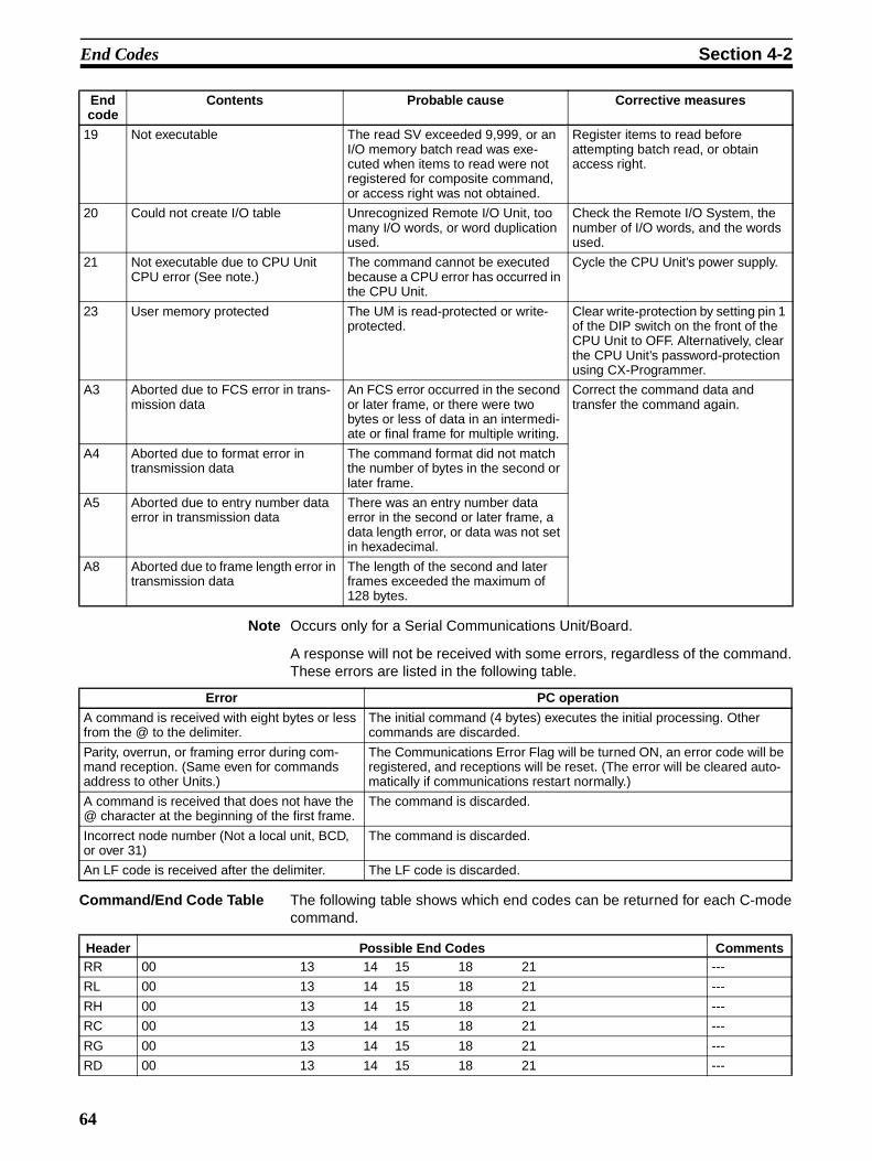
End Codes Section 4-2
Note Occurs only for a Serial Communications Unit/Board.
A response will not be received with some errors, regardless of the command.These errors are listed in the following table.
Command/End Code Table The following table shows which end codes can be returned for each C-modecommand.
19 Not executable The read SV exceeded 9,999, or an I/O memory batch read was exe-cuted when items to read were not registered for composite command, or access right was not obtained.
Register items to read before attempting batch read, or obtain access right.
20 Could not create I/O table Unrecognized Remote I/O Unit, too many I/O words, or word duplication used.
Check the Remote I/O System, the number of I/O words, and the words used.
21 Not executable due to CPU Unit CPU error (See note.)
The command cannot be executed because a CPU error has occurred in the CPU Unit.
Cycle the CPU Unit’s power supply.
23 User memory protected The UM is read-protected or write-protected.
Clear write-protection by setting pin 1 of the DIP switch on the front of the CPU Unit to OFF. Alternatively, clear the CPU Unit’s password-protection using CX-Programmer.
A3 Aborted due to FCS error in trans-mission data
An FCS error occurred in the second or later frame, or there were two bytes or less of data in an intermedi-ate or final frame for multiple writing.
Correct the command data and transfer the command again.
A4 Aborted due to format error in transmission data
The command format did not match the number of bytes in the second or later frame.
A5 Aborted due to entry number data error in transmission data
There was an entry number data error in the second or later frame, a data length error, or data was not set in hexadecimal.
A8 Aborted due to frame length error in transmission data
The length of the second and later frames exceeded the maximum of 128 bytes.
End code
Contents Probable cause Corrective measures
Error PC operation
A command is received with eight bytes or less from the @ to the delimiter.
The initial command (4 bytes) executes the initial processing. Other commands are discarded.
Parity, overrun, or framing error during com-mand reception. (Same even for commands address to other Units.)
The Communications Error Flag will be turned ON, an error code will be registered, and receptions will be reset. (The error will be cleared auto-matically if communications restart normally.)
A command is received that does not have the @ character at the beginning of the first frame.
The command is discarded.
Incorrect node number (Not a local unit, BCD, or over 31)
The command is discarded.
An LF code is received after the delimiter. The LF code is discarded.
Header Possible End Codes CommentsRR 00 13 14 15 18 21 ---
RL 00 13 14 15 18 21 ---
RH 00 13 14 15 18 21 ---
RC 00 13 14 15 18 21 ---
RG 00 13 14 15 18 21 ---
RD 00 13 14 15 18 21 ---
64

C-mode Command Details Section 4-3
4-3 C-mode Command Details
4-3-1 About this SectionWith C-mode command and response formats, a single character is indicatedby a single box. Each character is sent and received as a single byte in ASCII.
Execution Conditions The Execution Conditions table at the beginning of the description of eachcommand provides the following information.
Commands, SingleSingle command frames are used when there are 131 characters or less.
Commands, MultipleTells whether the command can be spit into multiple frames when there aremore than 131 characters.
Responses, SingleSingle response frames are used when there are 131 characters or less.
RJ 00 13 14 15 18 21 ---
RE 00 13 14 15 18 21 ---
WR 00 01 13 14 15 18 21 A3 A4 A5 A8 ---
WL 00 01 13 14 15 18 21 A3 A4 A5 A8 ---
WH 00 01 13 14 15 18 21 A3 A4 A5 A8 ---
WC 00 01 13 14 15 18 21 A3 A4 A5 A8 ---
WD 00 01 13 14 15 18 27 A3 A4 A5 A8 ---
WJ 00 01 13 14 15 18 21 A3 A4 A5 A8 ---
WE 00 01 13 14 15 18 21 A3 A4 A5 A8 ---
R# 00 13 14 15 16 18 21 23 ---
R$ 00 04 13 14 15 16 18 21 23 ---
R% 00 04 13 14 15 16 18 21 23 ---
W# 00 01 04 13 14 15 16 18 19 21 23 ---
W$ 00 01 04 13 14 15 16 18 19 21 23 ---
W% 00 01 04 13 14 15 16 18 19 21 23 ---
MS 00 13 14 18 21 ---
SC 00 13 14 15 18 19 21 ---
MF 00 01 02 13 14 15 18 19 21 ---
KS 00 01 13 14 15 18 21 ---
KR 00 01 13 14 15 18 21 ---
FK 00 01 13 14 15 18 21 ---
KC 00 01 13 14 15 18 21 ---
MM 00 13 14 18 21 ---
TS 13 14 18 21 ---
RP 00 13 14 18 19 21 23 ---
WP 00 01 02 13 14 15 18 19 21 23 A3 A4 A5 A8 ---
MI 00 01 02 03 13 14 18 19 20 ---
QQMR 00 13 14 15 18 21 A3 A4 A5 A8 ---
QQIR 00 13 14 18 19 ---
XZ --- No response
�� --- No response
IC --- No end code
Header Possible End Codes Comments
65

C-mode Command Details Section 4-3
Responses, MultipleTells whether the response can be spit into multiple frames when there aremore than 131 characters.
PC Modes, RUNTells if the CPU Unit will accept the command when the CPU Unit is in RUNmode.
PC Modes, MONITORTells if the CPU Unit will accept the command when the CPU Unit is in MONI-TOR mode.
PC Modes, PROGRAMTells if the CPU Unit will accept the command when the CPU Unit is in PRO-GRAM mode.
UM Area, Write-protectedTells if the CPU Unit will accept the command when the UM Area is write-pro-tected using the DIP switch on the CPU Unit.
UM Area, Read-protectedTells if the CPU Unit will accept the command when the UM Area is read-pro-tected using a Programming Device.
Note 1. WR Area words cannot be read or written using C-mode commands.
2. Timers 2048 to 4095 and counters 2048 to 4095 cannot be read or writtenand their SV cannot be read or written using C-mode commands.
3. D10000 to D32767 and E10000 to E32767 cannot be read or written usingC-mode commands.
4. SV can be read and written only in cyclic task 0. Also, timer SV can be readand written only when the timer number is not indirectly addressed.
4-3-2 CIO AREA READ – – RRReads the contents of the specified number of CIO words starting from thespecified word.
Command Format
Response Format
Limitations The text portion of the response’s first frame can contain up to 30 words. Ifmore than 30 words are read, the data will be returned in multiple frames.
In the second and later frames, the text portion of the response can containup to 31 words.
The INITIALIZE and ABORT commands can be sent instead of the delimiterfor multiple responses for this command. If other commands are sent, they willbe treated as delimiters.
@
FCS
x 101 x 100 x 103 x 102* ↵R R x 101 x 100 x 103 x 102 x 101 x 100
Unit No. (BCD) Header code
Beginning word (0000 to 6143)
No. of words (0001 to 6144)
Terminator
@ R Rx 101 x 100 x 161 x 160 x 163 x 162 x 161 x 160
FCS
* ↵
End code Read data (1 word)
Read data (for number of words read)
TerminatorUnit No. (BCD) Header code
66
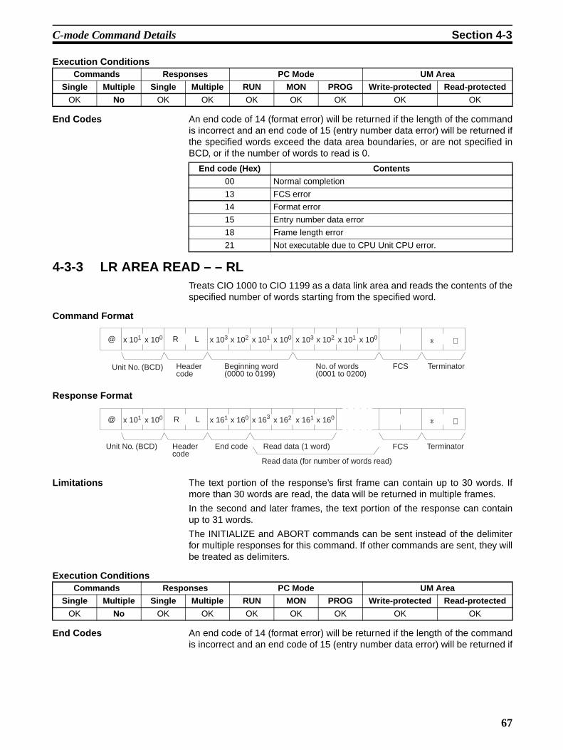
C-mode Command Details Section 4-3
Execution Conditions
End Codes An end code of 14 (format error) will be returned if the length of the commandis incorrect and an end code of 15 (entry number data error) will be returned ifthe specified words exceed the data area boundaries, or are not specified inBCD, or if the number of words to read is 0.
4-3-3 LR AREA READ – – RLTreats CIO 1000 to CIO 1199 as a data link area and reads the contents of thespecified number of words starting from the specified word.
Command Format
Response Format
Limitations The text portion of the response’s first frame can contain up to 30 words. Ifmore than 30 words are read, the data will be returned in multiple frames.
In the second and later frames, the text portion of the response can containup to 31 words.
The INITIALIZE and ABORT commands can be sent instead of the delimiterfor multiple responses for this command. If other commands are sent, they willbe treated as delimiters.
Execution Conditions
End Codes An end code of 14 (format error) will be returned if the length of the commandis incorrect and an end code of 15 (entry number data error) will be returned if
Commands Responses PC Mode UM Area
Single Multiple Single Multiple RUN MON PROG Write-protected Read-protected
OK No OK OK OK OK OK OK OK
End code (Hex) Contents
00 Normal completion
13 FCS error
14 Format error
15 Entry number data error
18 Frame length error
21 Not executable due to CPU Unit CPU error.
@
FCS
R Lx 101 x 100 x 103 x 102* ↵x 101 x 100 x 103 x 102 x 101 x 100
Unit No. (BCD) Header code
Beginning word (0000 to 0199)
No. of words (0001 to 0200)
Terminator
FCS
@ R Lx 101 x 100 x 161 x 160* ↵x 163 x 162 x 161 x 160
Unit No. (BCD) Header code
End code Read data (1 word)
Read data (for number of words read)
Terminator
Commands Responses PC Mode UM Area
Single Multiple Single Multiple RUN MON PROG Write-protected Read-protected
OK No OK OK OK OK OK OK OK
67

C-mode Command Details Section 4-3
the specified words exceed the data area boundaries, or are not specified inBCD, or if the number of words to read is 0.
Note The command is provided for compatibility with previous models. We recom-mend using CIO AREA READ (RR) whenever possible.
4-3-4 HR AREA READ – – RHReads the contents of the specified number of HR words starting from thespecified word.
Command Format
Response Format
Limitations The text portion of the response’s first frame can contain up to 30 words. Ifmore than 30 words are read, the data will be returned in multiple frames.
In the second and later frames, the text portion of the response can containup to 31 words.
The INITIALIZE and ABORT commands can be sent instead of the delimiterfor multiple responses for this command. If other commands are sent, they willbe treated as delimiters.
Execution Conditions
End Codes An end code of 14 (format error) will be returned if the length of the commandis incorrect and an end code of 15 (entry number data error) will be returned ifthe specified words exceed the data area boundaries, or are not specified inBCD, or if the number of words to read is 0.
End code (Hex) Contents
00 Normal completion
13 FCS error
14 Format error
15 Entry number data error
18 Frame length error
21 Not executable due to CPU Unit CPU error.
@
FCS
R Hx 101 x 100 x 103 x 102* ↵x 101 x 100 x 103 x 102 x 101 x 100
Unit No. (BCD)
Header code
Beginning word (0000 to 0511)
No. of words (0001 to 0512)
Terminator
@ R Hx 101 x 100 x 161 x 160* ↵x 163 x 162 x 161 x 160
FCSRead data (1 word)Header code
Unit No. (BCD)
End code Terminator
Read data (for number of words read)
Commands Responses PC Mode UM Area
Single Multiple Single Multiple RUN MON PROG Write-protected Read-protected
OK No OK OK OK OK OK OK OK
End code (Hex) Contents
00 Normal completion
13 FCS error
14 Format error
15 Entry number data error
68

C-mode Command Details Section 4-3
4-3-5 TIMER/COUNTER PV READ – – RCReads the contents of the specified number of timer/counter PVs (present val-ues T0000 to T2047 or C0000 to C2047) starting from the specified timer/counter.
Command Format
Response Format
Limitations The text portion of the response’s first frame can contain up to 30 words. Ifmore than 30 words are read, the data will be returned in multiple frames.
In the second and later frames, the text portion of the response can containup to 31 words.
The INITIALIZE and ABORT commands can be sent instead of the delimiterfor multiple responses for this command. If other commands are sent, they willbe treated as delimiters.
Designate 0000 to 2047 for timers and 2048 to 4095 for counters (add 2048 tothe actual counter number).
Timers T2048 to T4095 and counters T2048 to T4095 cannot be read.
Commands are divided among timers and counters for execution. If anattempt is made to designate across timers and counters, an end code of 15(entry number data error) will be returned.
Execution Conditions
End Codes An end code of 14 (format error) will be returned if the length of the commandis incorrect and an end code of 15 (entry number data error) will be returned ifthe specified words exceed the data area boundaries, or are not specified inBCD, or if the number of words to read is 0.
18 Frame length error
21 Not executable due to CPU Unit CPU error.
End code (Hex) Contents
@
FCS
R Cx 101 x 100 x 103 x 102* ↵x 101 x 100 x 103 x 102 x 101 x 100
No. of words(0001 to 2048)
Beginning word:Timer (0000 to 2047)Counter (2048 to 4095)
Header code
Unit No. (BCD) Terminator
@
FCS
R Cx 101 x 100* ↵x 103 x 102 x 101 x 100
TerminatorRead data (1 word)Read data (for number of words read)
Header code
Unit No. (BCD)
x 161 x 160
End code
Commands Responses PC Mode UM Area
Single Multiple Single Multiple RUN MON PROG Write-protected Read-protected
OK No OK OK OK OK OK OK OK
End code (Hex) Contents
00 Normal completion
13 FCS error
14 Format error
15 Entry number data error
69

C-mode Command Details Section 4-3
4-3-6 TIMER/COUNTER STATUS READ – – RGReads the ON/OFF status of the Completion Flags of the specified number oftimers/counters starting from the designated word (T0000 to T2047 or C0000to C2047).
Command Format
Response Format
Limitations The number of words per frame for response data is different to that for C-series Units. For details refer to ����� ������������������ �� ����� ���� �����������������.
The text portion of the response’s first frame can contain up to 121 words. Ifmore than 121 words are read, the data will be returned in multiple frames.
In the second and later frames, the text portion of the response can containup to 124 words.
The INITIALIZE and ABORT commands can be sent instead of the delimiterfor multiple responses for this command. If other commands are sent, they willbe treated as delimiters.
Designate 0000 to 2047 for timers and 2048 to 4095 for counters (add 2048 tothe actual counter number).
Timers T2048 to T4095 and counters C2048 to C4095 cannot be read.
Commands are divided with regard to timers and counters. If an attempt ismade to designate across timers and counters, an end code of 15 (entry num-ber data error) will be returned.
Execution Conditions
End Codes An end code of 14 (format error) will be returned if the length of the commandis incorrect and an end code of 15 (entry number data error) will be returned if
18 Frame length error
21 Not executable due to CPU Unit CPU error.
End code (Hex) Contents
@
FCS
R Gx 101 x 100 x 103 x 102* ↵x 101 x 100 x 103 x 102 x 101 x 100
Header code
Unit No. (BCD) No. of words(0001 to 2048)
TerminatorBeginning word:Timer (0000 to 2047)Counter (2048 to 4095)
@
FCS
R Gx 101 x 100 x 161 x 160* ↵
End codeHeader code
Unit No. (BCD)
TerminatorRead data(1 word)
Read data (for number of words read)
Commands Responses PC Mode UM Area
Single Multiple Single Multiple RUN MON PROG Write-protected Read-protected
OK No OK OK OK OK OK OK OK
70

C-mode Command Details Section 4-3
the specified words exceed the data area boundaries, or are not specified inBCD, or if the number of words to read is 0.
4-3-7 DM AREA READ – – RDReads the contents of the specified number of DM words starting from thespecified word (D00000 to D09999).
Command Format
Response Format
Limitations The DM Area is comprised of D00000 to D32767, but the range that can beread by this command is D00000 to D09999.
The text portion of the response’s first frame can contain up to 30 words. Ifmore than 30 words are read, the data will be returned in multiple frames.
In the second and later frames, the text portion of the response can containup to 31 words.
The INITIALIZE and ABORT commands can be sent instead of the delimiterfor multiple responses for this command. If other commands are sent, they willbe treated as delimiters.
Execution Conditions
End Codes An end code of 14 (format error) will be returned if the length of the commandis incorrect and an end code of 15 (entry number data error) will be returned ifthe specified words exceed the data area boundaries, or are not specified inBCD, or if the number of words to read is 0.
End code (Hex) Contents
00 Normal completion
13 FCS error
14 Format error
15 Entry number data error
18 Frame length error
21 Not executable due to CPU Unit CPU error.
@
FCS
R Dx 101 x 100 x 103 x 102* ↵x 101 x 100 x 103 x 102 x 101 x 100
Unit No. (BCD)
Header code
TerminatorBeginning word (0000 to 9999)
No. of words (0001 to 9999)
@ R Dx 101 x 100 x 161 x 160* ↵x 163 x 162 x 161 x 160
FCSUnit No. (BCD)
End codeHeader code
Read data (1 word)
Read data (for number of words read)
Terminator
Commands Responses PC Mode UM Area
Single Multiple Single Multiple RUN MON PROG Write-protected Read-protected
OK No OK OK OK OK OK OK OK
End code (Hex) Contents
00 Normal completion
13 FCS error
14 Format error
15 Entry number data error
71

C-mode Command Details Section 4-3
4-3-8 AR AREA READ – – RJReads the contents of the specified number of Auxiliary Area words (A000 toA959) starting from the specified word.
Command Format
Response Format
Limitations The text portion of the response’s first frame can contain up to 30 words. Ifmore than 30 words are read, the data will be returned in multiple frames.
In the second and later frames, the text portion of the response can containup to 31 words.
The INITIALIZE and ABORT commands can be sent instead of the delimiterfor multiple responses for this command. If other commands are sent, they willbe treated as delimiters.
Execution Conditions
End Codes An end code of 14 (format error) will be returned if the length of the commandis incorrect and an end code of 15 (entry number data error) will be returned ifthe specified words exceed the data area boundaries, or are not specified inBCD, or if the number of words to read is 0.
18 Frame length error
21 Not executable due to CPU Unit CPU error.
End code (Hex) Contents
@
FCS
R Jx 101 x 100 x 103 x 102* ↵x 101 x 100 x 103 x 102 x 101 x 100
TerminatorBeginning word (0000 to 0959)
Unit No. (BCD)
Header code
No. of words (0001 to 0960)
@
FCS
R Jx 101 x 100 x 161 x 160* ↵x 163 x 162 x 161 x 160
Unit No. (BCD)
End codeHeader code
Read data (1 word )
Read data (for number of words read)
Terminator
Commands Responses PC Mode UM Area
Single Multiple Single Multiple RUN MON PROG Write-protected Read-protected
OK No OK OK OK OK OK OK OK
End code (Hex) Contents
00 Normal completion
13 FCS error
14 Format error
15 Entry number data error
18 Frame length error
21 Not executable due to CPU Unit CPU error.
72
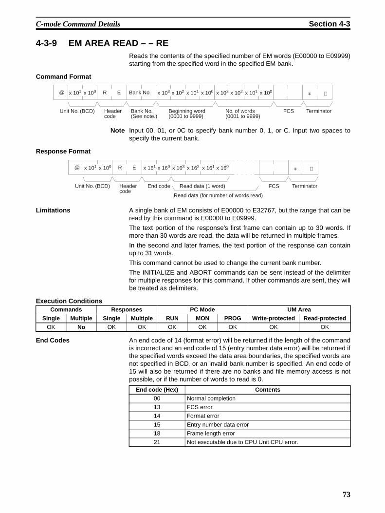
C-mode Command Details Section 4-3
4-3-9 EM AREA READ – – REReads the contents of the specified number of EM words (E00000 to E09999)starting from the specified word in the specified EM bank.
Command Format
Note Input 00, 01, or 0C to specify bank number 0, 1, or C. Input two spaces tospecify the current bank.
Response Format
Limitations A single bank of EM consists of E00000 to E32767, but the range that can beread by this command is E00000 to E09999.
The text portion of the response’s first frame can contain up to 30 words. Ifmore than 30 words are read, the data will be returned in multiple frames.
In the second and later frames, the text portion of the response can containup to 31 words.
This command cannot be used to change the current bank number.
The INITIALIZE and ABORT commands can be sent instead of the delimiterfor multiple responses for this command. If other commands are sent, they willbe treated as delimiters.
Execution Conditions
End Codes An end code of 14 (format error) will be returned if the length of the commandis incorrect and an end code of 15 (entry number data error) will be returned ifthe specified words exceed the data area boundaries, the specified words arenot specified in BCD, or an invalid bank number is specified. An end code of15 will also be returned if there are no banks and file memory access is notpossible, or if the number of words to read is 0.
@
FCS
R Ex 101 x 100 x 103 x 102* ↵x 101 x 100 x 103 x 102 x 101 x 100
Unit No. (BCD) Header code
TerminatorBeginning word (0000 to 9999)
No. of words (0001 to 9999)
Bank No.(See note.)
Bank No.
@ R Ex 101 x 100 x 161 x 160* ↵x 163 x 162 x 161 x 160
FCSUnit No. (BCD) End codeHeader code
Read data (1 word)
Read data (for number of words read)
Terminator
Commands Responses PC Mode UM Area
Single Multiple Single Multiple RUN MON PROG Write-protected Read-protected
OK No OK OK OK OK OK OK OK
End code (Hex) Contents
00 Normal completion
13 FCS error
14 Format error
15 Entry number data error
18 Frame length error
21 Not executable due to CPU Unit CPU error.
73

C-mode Command Details Section 4-3
4-3-10 CIO AREA WRITE – – WRWrites data to the CIO Area (CIO 0000 to CIO 6143) starting from the speci-fied word. Writing is done in word units.
Command Format
Response Format
Execution Conditions
End Codes An end code of 14 (format error) will be returned if the length of the commandis incorrect or the first word of write data is not in the first frame.
An end code of 15 (entry number data error) will be returned if the specifiedwrite data exceeds the data area boundaries, the beginning word is not speci-fied in BCD, or the write data is not hexadecimal. (An end code of A5 will bereturned instead of 15 for non-hexadecimal write data in multiple commandframes.)
@
FCS
W Rx 101 x 100 x 103 x 102* ↵x 101 x 100 x 163 x 162 x 161 x 160
Unit No. (BCD) Header code
Beginning word (0000 to 6143)
Write data (1 word)
Write data (for number of words to write)
Terminator
@ W Rx 101 x 100 x 161 x 160
FCS
* ↵
Unit No. (BCD) End codeHeader code
Terminator
Commands Responses PC Mode UM Area
Single Multiple Single Multiple RUN MON PROG Write-protected Read-protected
OK OK OK No No OK OK OK OK
End code (Hex) Contents
00 Normal completion
01 Not executable in RUN mode
13 FCS error
14 Format error
15 Entry number data error
18 Frame length error
21 Not executable due to CPU Unit CPU error.
A3 Aborted due to FCS error in transmit data
A4 Aborted due to format error in transmit data
A5 Aborted due to entry number data error in transmit data
A8 Aborted due to frame length error in transmit data
74

C-mode Command Details Section 4-3
4-3-11 LR AREA WRITE – – WLWrites data to the Link Area (CIO 1000 to CIO 1199) starting from the speci-fied word. Writing is done in word units.
Command Format
Response Forma
Execution Conditions
End Codes An end code of 14 (format error) will be returned if the length of the commandis incorrect.
An end code of 15 (entry number data error) will be returned if the specifiedwrite data exceeds the data area boundary, the beginning word is not speci-fied in BCD, or the write data is not hexadecimal. (An end code of A5 will bereturned instead of 15 for non-hexadecimal write data in multiple commandframes.)
Note The command is provided for compatibility with previous models. We recom-mend using CIO AREA WRITE (WR) whenever possible.
@
FCS
W Lx 101 x 100 x 103 x 102* ↵x 101 x 100 x 163 x 162 x 161 x 160
Unit No. (BCD) Header code
TerminatorWrite data (1 word)
Write data (for number of words to write )
Beginning word (000 to 0199)
@
FCS
W Lx 101 x 100 x 161 x 160* ↵
Unit No. (BCD) End codeHeader code
Terminator
Commands Responses PC Mode UM Area
Single Multiple Single Multiple RUN MON PROG Write-protected Read-protected
OK OK OK No No OK OK OK OK
End code (Hex) Contents
00 Normal completion
01 Not executable in RUN mode
13 FCS error
14 Format error
15 Entry number data error
18 Frame length error
21 Not executable due to CPU Unit CPU error.
A3 Aborted due to FCS error in transmit data
A4 Aborted due to format error in transmit data
A5 Aborted due to entry number data error in transmit data
A8 Aborted due to frame length error in transmit data
75

C-mode Command Details Section 4-3
4-3-12 HR AREA WRITE – – WHWrites data to the HR Area (H000 to H511) starting from the specified word.Writing is done in word units.
Command Format
Response Format
Execution Conditions
End Codes An end code of 14 (format error) will be returned if the length of the commandis incorrect or the first word of write data is not in the first frame.
An end code of 15 (entry number data error) will be returned if the specifiedwrite data exceeds the data area boundary, the beginning word is not speci-fied in BCD, or the write data is not hexadecimal. (An end code of A5 will bereturned instead of 15 for non-hexadecimal write data in multiple commandframes.)
@
FCS
W Hx 101 x 100 x 103 x 102* ↵x 101 x 100 x 163 x 162 x 161 x 160
Unit No. (BCD)
Header code
Beginning word (0000 to 0511)
Write data (for no. of words to write)
Write data (1 word) Terminator
@
FCS
W Hx 101 x 100 x 161 x 160* ↵
Unit No. (BCD)
End codeHeader code
Terminator
Commands Responses PC Mode UM Area
Single Multiple Single Multiple RUN MON PROG Write-protected Read-protected
OK OK OK No No OK OK OK OK
End code (Hex) Contents
00 Normal completion
01 Not executable in RUN mode
13 FCS error
14 Format error
15 Entry number data error
18 Frame length error
21 Not executable due to CPU Unit CPU error.
A3 Aborted due to FCS error in transmit data
A4 Aborted due to format error in transmit data
A5 Aborted due to entry number data error in transmit data
A8 Aborted due to frame length error in transmit data
76

C-mode Command Details Section 4-3
4-3-13 TIMER/COUNTER PV WRITE – – WCWrites the PVs (present values T0000 to T2047 or C0000 to C2047) of timers/counters starting from the specified word.
Command Format
Response Format
Limitations Commands are divided with regard to timers and counters. If an attempt ismade to designate across timers and counters, an end code of 15 (entry num-ber data error) will be returned.
Execution Conditions
End Codes An end code of 14 (format error) will be returned if the length of the commandis incorrect.
An end code of 15 (entry number data error) will be returned if the specifiedwrite data exceeds the data area boundary, the beginning word is not speci-fied in BCD, or the write data is not hexadecimal. (An end code of A5 will bereturned instead of 15 for non-hexadecimal write data in multiple commandframes.)
@
FCS
W Cx 101 x 100 x 103 x 102* ↵x 101 x 100 x 163 x 162 x 161 x 160
Unit No. (BCD) Header code
TerminatorBeginning wordTimer (0000 to 2047)Counter (2048 to 4095)
Write data (1 word)
Write data (for no. of PV to write)
@
FCS
W Cx 101 x 100 x 161 x 160* ↵
Unit No. (BCD) End codeHeader code
Terminator
Commands Responses PC Mode UM Area
Single Multiple Single Multiple RUN MON PROG Write-protected Read-protected
OK OK OK No No OK OK OK OK
End code (Hex) Contents
00 Normal completion
01 Not executable in RUN mode
13 FCS error
14 Format error
15 Entry number data error
18 Frame length error
21 Not executable due to CPU Unit CPU error.
A3 Aborted due to FCS error in transmit data
A4 Aborted due to format error in transmit data
A5 Aborted due to entry number data error in transmit data
A8 Aborted due to frame length error in transmit data
77

C-mode Command Details Section 4-3
4-3-14 DM AREA WRITE – – WDWrites data to the DM Area starting from the specified word (D00000 toD09999). Writing is done in word units.
Command Format
Response Format
Limitations The DM Area is comprised of D00000 to D32767, but the range that can beread by this command is D00000 to D09999.
Execution Conditions
End Codes An end code of 14 (format error) will be returned if the length of the commandis incorrect or the first word of write data is not in the first frame.
An end code of 15 (entry number data error) will be returned if the specifiedwrite data exceeds the data area boundary, the beginning word is not speci-fied in BCD, or the write data is not hexadecimal. (An end code of A5 will bereturned instead of 15 for non-hexadecimal write data in multiple commandframes.)
@
FCS
W Dx 101 x 100 x 103 x 102* ↵x 101 x 100 x 163 x 162 x 161 x 160
Unit No. (BCD) Header code
Beginning word (0000 to 9999)
Write data (1 word)
Write data (for number of words to write)
Terminator
@ W Dx 101 x 100 x 161 x 160* ↵
FCSUnit No. (BCD) Header code
TerminatorEnd code
Commands Responses PC Mode UM Area
Single Multiple Single Multiple RUN MON PROG Write-protected Read-protected
OK OK OK No No OK OK OK OK
End code (Hex) Contents
00 Normal completion
01 Not executable in RUN mode
13 FCS error
14 Format error
15 Entry number data error
18 Frame length error
21 Not executable due to CPU Unit CPU error.
A3 Aborted due to FCS error in transmit data
A4 Aborted due to format error in transmit data
A5 Aborted due to entry number data error in transmit data
A8 Aborted due to frame length error in transmit data
78

C-mode Command Details Section 4-3
4-3-15 AR AREA WRITE – – WJWrites data to the Auxiliary Area (A448 to A959) starting from the specifiedword. Writing is done in word units.
Command Format
Response Format
Execution Conditions
End Codes An end code of 14 (format error) will be returned if the length of the commandis incorrect or the first word of write data is not in the first frame.
An end code of 15 (entry number data error) will be returned if the specifiedwrite data exceeds the data area boundary, the beginning word is not speci-fied in BCD, or the write data is not hexadecimal. (An end code of A5 will bereturned instead of 15 for non-hexadecimal write data in multiple commandframes.)
@
FCS
W Jx 101 x 100 x 103 x 102* ↵x 101 x 100 x 163 x 162 x 161 x 160
Write data (for the number of words to write)
Write data (1 word)Beginning word (0448 to 0959)
Unit No. (BCD) Header code
Terminator
@
FCS
W Jx 101 x 100 x 161 x 160* ↵
Unit No. (BCD) End codeHeader code
Terminator
Commands Responses PC Mode UM Area
Single Multiple Single Multiple RUN MON PROG Write-protected Read-protected
OK OK OK No No OK OK OK OK
End code (Hex) Contents
00 Normal completion
01 Not executable in RUN mode
13 FCS error
14 Format error
15 Entry number data error
18 Frame length error
21 Not executable due to CPU Unit CPU error.
A3 Aborted due to FCS error in transmit data
A4 Aborted due to format error in transmit data
A5 Aborted due to entry number data error in transmit data
A8 Aborted due to frame length error in transmit data
79

C-mode Command Details Section 4-3
4-3-16 EM AREA WRITE – – WEWrites data to the specified EM Area bank starting from the specified word(E00000 to E09999). Writing is done in word units.
Command Format
Note Input 00 to 0C to specify bank number 0 to C. Input two spaces to specify thecurrent bank.
Response Format
Limitations The range that can be designated is E0000 to E9999. A single bank of EMconsists of E00000 to E32767, but the range that can be written by this com-mand is E00000 to E09999.
Execution Conditions
End Codes An end code of 14 (format error) will be returned if the length of the commandis incorrect or the first word of write data is not in the first frame.
An end code of 15 (entry number data error) will be returned if the specifiedwrite data exceeds the data area boundary, the beginning word is not speci-fied in BCD, or the write data is not hexadecimal. An end code of 15 will alsobe returned if there are no banks and file memory access is not possible. (Anend code of A5 will be returned instead of 15 for non-hexadecimal write datain multiple command frames.)
@
FCS
W Ex 101 x 100 x 103 x 102* ↵x 101 x 100 x 163 x 162 x 161 x 160
Unit No. (BCD) Header code
Beginning word (0000 to 9999)
Write data (1 word)
Write data (for number of words to write)
TerminatorBank No.(See note.)
Bank No.
@ W Ex 101 x 100 x 161 x 160* ↵
FCSUnit No. (BCD) Header code
TerminatorEnd code
Commands Responses PC Mode UM Area
Single Multiple Single Multiple RUN MON PROG Write-protected Read-protected
OK OK OK No No OK OK OK OK
End code (Hex) Contents
00 Normal completion
01 Not executable in RUN mode
13 FCS error
14 Format error
15 Entry number data error
18 Frame length error
21 Not executable due to CPU Unit CPU error.
A3 Aborted due to FCS error in transmit data
A4 Aborted due to format error in transmit data
A5 Aborted due to entry number data error in transmit data
A8 Aborted due to frame length error in transmit data
80

C-mode Command Details Section 4-3
4-3-17 TIMER/COUNTER SV READ 1 – – R#Reads the constant SV (4 digits BCD) written in the operands of designatedtimer/counter instructions from cyclic task 0. If there are multiple timer/counterinstructions designated in cyclic task 0, TIMER/COUNTER SV READ 1 willread the SV of the designated instruction with the lowest program address.
Command Format
Note “SP” represents a space (20 Hex).
Response Format
Parameters Timer/Counter Type (Command)Designate in ASCII characters the type of TC instruction for reading the con-stant SV.
Timer Counter Number (Command)Designate in four digits (BCD) the timer/counter number for reading the con-stant SV.
Limitations Timers T2048 to T4095 and counters C2048 to C4095 cannot be read.
The second word of the instruction must be a constant.
If there are multiple relevant instructions in the UM Area, a search will be con-ducted from program address 0, and the first instruction found will be read.
SV can be read only from cyclic task 0.
Execution Conditions
@
FCS
R #x 101 x 100* ↵x 103 x 102 x 101 x 100
Unit No. (BCD) Header code
TerminatorTimer/counter number
Timer/counter type
Instruction name Timer/counter type Timer/counter number (BCD)Char-
acter 1Char-
acter 2Char-
acter 3Char-
acter 4
HIGH-SPEED COUNTER WAIT
T M H W 0000 to 2047
TIMER WAIT T I M W
COUNTER WAIT C N T W
HIGH-SPEED TIMER T I M H
TOTALIZING TIMER T T I M
REVERSIBLE COUNTER C N T R
TIMER T I M (SP)
COUNTER C N T (SP)
@
FCS
R #x 101 x 100 x 161 x 160* ↵x 103 x 102 x 101 x 100
SV of instruction designated by command (constant)
TerminatorUnit No. (BCD) Header code
End code
Commands Responses PC Mode UM Area
Single Multiple Single Multiple RUN MON PROG Write-protected Read-protected
OK No OK No OK OK OK OK No
81

C-mode Command Details Section 4-3
End Codes An end code of 14 (format error) will be returned if the length of the commandis incorrect.
An end code of 15 (entry number data error) will be returned if the timer/counter type or timer/counter number is out of range (including hexadecimaldata).
An end code of 16 (command not supported) will be returned if the specifiedinstruction does not exist in the UM Area.
4-3-18 TIMER/COUNTER SV READ 2 – – R$From the specified program address onwards in cyclic task 0, TIMER/COUNTER SV READ 2 finds the specified timer/counter instruction and readsthe 4-digit constant SV that is set or the word address where the SV is stored.
Command Format
Note “SP” represents a space (20 Hex).
End code (Hex) Contents
00 Normal completion
13 FCS error
14 Format error
15 Entry number data error
16 Command not supported
18 Frame length error
21 Not executable due to CPU Unit CPU error.
23 User memory protected
Instruction name Timer/counter type Timer/counter number (BCD)Char-
acter 1Char-
acter 2Char-
acter 3Char-
acter 4
HIGH-SPEED COUNTER WAIT
T M H W 0000 to 2047
TIMER WAIT T I M W
COUNTER WAIT C N T W
HIGH-SPEED TIMER T I M H
TOTALIZING TIMER T T I M
REVERSIBLE COUNTER C N T R
TIMER T I M (SP)
COUNTER C N T (SP)
x 100 x 100@ R $x 100x 101 x 103 x 102 x 101 OP1 OP2 OP3 OP4 x 103 x 102 x 101 * ↵
Unit No. (BCD) Program address (BCD)
Timer/counter type Timer/counter number (BCD)
TerminatorFCSHeader code
82

C-mode Command Details Section 4-3
Response Format
Note “SP” represents a space (20 Hex).
Parameters Program Address (Command)Designates the program address in four digits decimal (BCD) for beginningthe search for the specified timer/counter.
Timer/Counter Type (Command)Designate in ASCII characters the timer/counter instruction type for readingthe constant SV or the word address in which it is stored.
Timer/Counter Number (Command)Designate in four digits (BCD) the timer/counter instruction number for read-ing the constant SV or the word address in which it is stored. (Data registerdesignation is not possible.)
Constant/Area Classification (Response)The constant or I/O memory area classification is returned, in ASCII, to thisparameter.
SV/Word Address (Response)The constant SV or the word address in which it is stored is returned to thisparameter.
Limitations Timers T2048 to T4095 and counters C2048 to C4095 cannot be read.
The SV of the first timer/counter found after the designated program addresswill be read.
If the SV is outside of range for the timer/counter type or number, an end codeof 16 (command not supported) will be returned.
Classification Constant/area classification SV or word addressCharac-
ter 1Charac-
ter 2Charac-
ter 3Charac-
ter 4
Constant C O N (SP) 0000 to 9999
CIO C I O (SP) 0000 to 6143
AR A R (SP) (SP) 0000 to 0959
HR H R (SP) (SP) 0000 to 0511
WR W R (SP) (SP) 0000 to 0511
Timer T I M (SP) 0000 to 2047
Counter C N T (SP) 0000 to 2047
DM D M (SP) (SP) 0000 to 9999
DM (indirect) D M � (SP) 0000 to 9999
EM current bank E M (SP) (SP) 0000 to 9999
EM (indirect) current bank
E M � (SP) 0000 to 9999
EM banks 0 to C E M 0 to C (SP) 0000 to 9999
EM (indirect) banks 0 to C
E M 0 to C � 0000 to 9999
Data register D R (SP) (SP) 0000 to 0015
Index register (indirect) , I R (SP) 0000 to 0015
x 160@ R $ OP1 OP2 OP3 OP4 x 100x 100x 101 x 161 x 103 x 102 x 101 ↵*
Unit No. (BCD) Header code
End code Constant/area classification
SV/word address TerminatorFCS
83

C-mode Command Details Section 4-3
If the SV is a DM or EM indirect address, only indirect BCD designations willbe read and an end code of 16 (command not supported) will be returned ifthe indirect designation is not BCD.
SV can be read only from cyclic task 0.
Execution Conditions
End Codes An end code of 14 (format error) will be returned if the length of the commandis incorrect.
An end code of 15 (entry number data error) will be returned if the programaddress is not specified in BCD or the operand/SV parameters are incorrect.
An end code of 16 (command not supported) will be returned if the specifiedinstruction does not exist in the UM Area.
4-3-19 TIMER/COUNTER SV READ 3 – – R%From the specified program address onwards in cyclic task 0, TIMER/COUNTER SV READ 3 finds the specified TC instruction and reads the con-stant SV that is set or the word address where the SV is stored. The SV that isread is a 4-digit decimal number (BCD).
Commands Responses PC Mode UM Area
Single Multiple Single Multiple RUN MON PROG Write-protected Read-protected
OK No OK No OK OK OK OK No
End code (Hex) Contents
00 Normal completion
04 Address over
13 FCS error
14 Format error
15 Entry number data error
16 Command not supported
18 Frame length error
21 Not executable due to CPU Unit CPU error.
23 User memory protected
84

C-mode Command Details Section 4-3
Command Format
Note “SP” represents a space (20 Hex).
Response Format
Instruction name Timer/counter type Timer/counter numberChar-
acter 1Char-
acter 2Char-
acter 3Char-
acter 4
HIGH-SPEED TIMER WAIT
T M H W 0000 to 2047
TIMER WAIT T I M W
COUNTER WAIT C N T W
HIGH-SPEED TIMER T I M H
TOTALIZING TIMER T T I M
REVERSIBLE COUNTER C N T R
TIMER T I M (SP)
COUNTER C N T (SP)
x 103OP4OP3OP2OP1@ R % x 102 x 102x 100x 101 x 105 x 104 x 103 x 100x 101x 101 x 100
↵*
Unit No. (BCD) Program address Timer/counter type Timer/counter number
TerminatorFCS
Header code
Classification Constant/area classification Constant or word addressCharac-
ter 1Charac-
ter 2Charac-
ter 3Charac-
ter 4
Constant C O N (SP) 0000 to 9999
CIO C I O (SP) 0000 to 6143
AR A R (SP) (SP) 0000 to 0959
HR H R (SP) (SP) 0000 to 0511
WR W R (SP) (SP) 0000 to 0511
Timer T I M (SP) 0000 to 2047
Counter C N T (SP) 0000 to 2047
DM D M (SP) (SP) 0000 to 9999
DM (indirect) D M � (SP) 0000 to 9999
EM current bank E M (SP) (SP) 0000 to 9999
EM (indirect) current bank
E M � (SP) 0000 to 9999
EM banks 0 to C E M 0 to C (SP) 0000 to 9999
EM (indirect) banks 0 to C
E M 0 to C � 0000 to 9999
Data register D R (SP) (SP) 0000 to 0015
Index register (indirect) , I R (SP) 0000 to 0015
@ R % OP1 OP2 OP3 OP4x 160 x 100x 100x 101 x 161 x 103 x 102 x 101 * ↵
Unit No. (BCD) Header code
End code Constant/area classification
SV/word address TerminatorFCS
85

C-mode Command Details Section 4-3
Note “SP” represents a space (20 Hex).
Parameters Program Address (Command)Designates the program address in six digits decimal (BCD) for beginning thesearch for the specified timer/counter.
Timer/Counter Type (Command)Designate the timer/counter instruction type for reading the constant SV or theword address in which it is stored.
Timer/Counter Number (Command)Designate the timer/counter instruction number for reading the constant SV orthe word address in which it is stored. (Index register designation is not possi-ble.)
Constant/Area Classification (Response)The constant or I/O memory area classification is returned, in ASCII, to thisparameter.
SV/Word Address (Response)The constant SV or the word address in which it is stored is returned to thisparameter.
Limitations Timers T2048 to T4095 and counters C2048 to C4095 cannot be read.
The SV of the first timer/counter found after the designated program addresswill be read.
If the SV is outside of range for the timer/counter type or number, an end codeof 16 (command not supported) will be returned.
If the SV is a DM or EM indirect address, only indirect BCD designations willbe read and an end code of 16 (command not supported) will be returned ifthe indirect designation is not BCD.
SV can be read only from cyclic task 0.
Execution Conditions
End Codes An end code of 14 (format error) will be returned if the length of the commandis incorrect.
An end code of 15 (entry number data error) will be returned if the programaddress is not specified in BCD, or if the timer/counter type or number is out ofrange (including hexadecimal data).
An end code of 16 (command not supported) will be returned if the specifiedinstruction does not exist in the program.
Commands Responses PC Mode UM Area
Single Multiple Single Multiple RUN MON PROG Write-protected Read-protected
OK No OK No OK OK OK OK No
End code (Hex) Contents
00 Normal completion
04 Address over
13 FCS error
14 Format error
15 Entry number data error
16 Command not supported
18 Frame length error
21 Not executable due to CPU Unit CPU error.
23 User memory protected
86

C-mode Command Details Section 4-3
4-3-20 TIMER/COUNTER SV CHANGE 1 – – W#Changes the SV of the designated timer/counter instruction to a new constantSV.
Command Format
Note “SP” represents a space (20 Hex).
Response Format
Parameters Timer/Counter Type (Command)Designate the timer/counter instruction type for changing the constant SV.
Timer/Counter Number (Command)Designate in four digits BCD the timer/counter instruction number for chang-ing the constant SV. (Index register designation is not possible.)
New Constant SV (Command)Designate the new constant SV in four digits hexadecimal.
Limitations Timers T2048 to T4095 and counters C2048 to C4095 cannot be read.
The command cannot be executed unless the SV is a constant.
If there are multiple relevant instructions in cyclic task 0, a search will be con-ducted from program address 0, and the first instruction found will be read.
The SV can be changed only in cyclic task 0.
If the SV is a DM or EM indirect address, only indirect BCD designations willbe read and an end code of 16 (command not supported) will be returned ifthe indirect designation is not BCD.
Execution Conditions
Instruction name Timer/counter type Timer/counter number (BCD)Char-
acter 1Char-
acter 2Char-
acter 3Char-
acter 4
HIGH-SPEED TIMER WAIT
T M H W 0000 to 2047
TIMER WAIT T I M W
COUNTER WAIT C N T W
HIGH-SPEED TIMER T I M H
TOTALIZING TIMER T T I M
REVERSIBLE COUNTER C N T R
TIMER T I M (SP)
COUNTER C N T (SP)
@ W # OP1 OP2 OP3 OP4x 100x 101 x 103 x 102 x 100x 101 ↵*x 103 x 102 x 100x 101
Unit No. (BCD) Header code
Timer/counter type Timer/counter number
SV (0000 to 9999 (BCD)) TerminatorFCS
@ W # x 160x 100x 101 x 161 ↵*
Unit No. (BCD) Header code
End code TerminatorFCS
Commands Responses PC Mode UM Area
Single Multiple Single Multiple RUN MON PROG Write-protected Read-protected
OK No OK No No OK OK No No
87

C-mode Command Details Section 4-3
End Codes An end code of 14 (format error) will be returned if the length of the commandis incorrect.
An end code of 15 (entry number data error) will be returned if the programaddress is not specified in BCD, or if the timer/counter type or number is out ofrange (including hexadecimal data).
An end code of 16 (command not supported) will be returned if the specifiedinstruction does not exist in the UM Area.
4-3-21 TIMER/COUNTER SV CHANGE 2 – – W$From the specified program address onwards in cyclic task 0, TIMER/COUNTER SV CHANGE 2 finds the specified timer/counter instruction andchanges the 4-digit constant SV (BCD) that is set, or the word address wherethe SV is stored, to a newly designated constant SV or storage word address.
Command Format
End code (Hex) Contents
00 Normal completion
01 Not executable in RUN mode
04 Address over
13 FCS error
14 Format error
15 Entry number data error
16 Command not supported
18 Frame length error
19 Not executable
21 Not executable due to CPU Unit CPU error.
23 User memory protected
Instruction name Timer/counter type Timer/counter numberCharac
ter 1Charac
ter 2Charac
ter 3Charac
ter 4
HIGH-SPEED TIMER WAIT
T M H W 0000 to 2047
TIMER WAIT T I M W
COUNTER WAIT C N T W
HIGH-SPEED TIMER T I M H
TOTALIZING TIMER T T I M
REVERSIBLE COUNTER C N T R
TIMER T I M (SP)
COUNTER C N T (SP)
OP4OP3OP2OP1@ W $ x 100x 100x 101 x 103 x 102 x 101 x 100x 103 x 102 x 101
OP4OP3OP2OP1 x 100x 103 x 102 x 101 * ↵
Unit No. (BCD) Program address
Timer/counter type Timer/counter numberHeader code
Constant/area classification New SV/word address TerminatorFCS
88

C-mode Command Details Section 4-3
Note “SP” represents a space (20 Hex).
Note “SP” represents a space (20 Hex).
Response Format
Parameters Program Address (Command)Designate the program address in four digits decimal (BCD) for beginning thesearch for the specified timer/counter instruction.
Timer/Counter Type (Command)Designate the timer/counter instruction type for changing the constant SV orthe word address in which it is stored.
Timer/Counter Number (Command)Designate the timer/counter instruction number for reading the constant SV.(Index register designation is not possible.) The range that can be designatedis the same as for R#.
Constant/Area Classification (Command)Designate the ASCII characters to express the new SV area classification orconstant.
New SV/Word Address (Command)Designate the newly set constant SV or the word address in which it is stored.
Limitations Timers T2048 to T4095 and counters C2048 to C4095 cannot be read.
The SV of the first timer/counter found after the designated program addresswill be read.
If the SV is outside of range for the timer/counter type or number, an end codeof 16 (command not supported) will be returned.
Classification Constant/area classification SV or word address (BCD)
Charac-ter 1
Charac-ter 2
Charac-ter 3
Charac-ter 4
Constant C O N (SP) 0000 to 9999
CIO C I O (SP) 0000 to 6143
AR A R (SP) (SP) 0000 to 0959
HR H R (SP) (SP) 0000 to 0511
WR W R (SP) (SP) 0000 to 0511
Timer T I M (SP) 0000 to 2047
Counter C N T (SP) 0000 to 2047
DM D M (SP) (SP) 0000 to 9999
DM (indirect) D M � (SP) 0000 to 9999
EM current bank E M (SP) (SP) 0000 to 9999
EM (indirect) current bank
E M � (SP) 0000 to 9999
EM banks 0 to C E M 0 to C (SP) 0000 to 9999
EM (indirect) 0 to C E M 0 to C � 0000 to 9999
Data register D R (SP) (SP) 0000 to 0015
Index register , I R (SP) 0000 to 0015
@ W $ x 160x 100x 101 x 161 * ↵
Unit No. (BCD) Header code
TerminatorFCSEnd code
89

C-mode Command Details Section 4-3
If the SV is a DM or EM indirect address, only indirect BCD designations willbe read and an end code of 16 (command not supported) will be returned ifthe indirect designation is not BCD.
The SV can be changed only in cyclic task 0.
Execution Conditions
End Codes An end code of 14 (format error) will be returned if the length of the commandis incorrect.
An end code of 15 (entry number data error) will be returned if the programaddress is not BCD, or if the timer/counter type or number is out of range(including hexadecimal data).
An end code of 16 (command not supported) will be returned if the specifiedinstruction does not exist in the UM Area.
4-3-22 TIMER/COUNTER SV CHANGE 3 – – W%From the specified program address onwards in cyclic task 0, TIMER/COUNTER SV CHANGE 3 finds the specified timer/counter instruction andchanges the 4-digit constant SV (BCD) that is set, or the word address wherethe SV is stored, to a newly designated constant SV or storage word address.
Commands Responses PC Mode UM Area
Single Multiple Single Multiple RUN MON PROG Write-protected Read-protected
OK No OK No No OK OK No No
End code (Hex) Contents
00 Normal completion
01 Not executable in RUN mode
04 Address over
13 FCS error
14 Format error
15 Entry number data error
16 Command not supported
18 Frame length error
19 Not executable
21 Not executable due to CPU Unit CPU error.
23 User memory protected
90

C-mode Command Details Section 4-3
Command Format
Note “SP” represents a space (20 Hex).
Note “SP” represents a space (20 Hex).
Instruction name Timer/counter type Timer/counter numberChar-
acter 1Char-
acter 2Char-
acter 3Char-
acter 4
HIGH-SPEED TIMER WAIT
T M H W 0000 to 2047
TIMER WAIT T I M W
COUNTER WAIT C N T W
HIGH-SPEED TIMER T I M H
TOTALIZING TIMER T T I M
REVERSIBLE COUNTER C N T R
TIMER T I M (SP)
COUNTER C N T (SP)
Classification Constant/area classification SV or word address (BCD)
Charac-ter 1
Charac-ter 2
Charac-ter 3
Charac-ter 4
Constant C O N (SP) 0000 to 9999
CIO C I O (SP) 0000 to 6143
AR A R (SP) (SP) 0000 to 0959
HR H R (SP) (SP) 0000 to 0511
WR W R (SP) (SP) 0000 to 0511
Timer T I M (SP) 0000 to 2047
Counter C N T (SP) 0000 to 2047
DM D M (SP) (SP) 0000 to 9999
DM (indirect) D M � (SP) 0000 to 9999
EM current bank E M (SP) (SP) 0000 to 9999
EM (indirect) current bank
E M � (SP) 0000 to 9999
EM banks 0 to C E M 0 to C (SP) 0000 to 9999
EM (indirect) 0 to C E M 0 to C � 0000 to 9999
Data register D R (SP) (SP) 0000 to 0015
Index register , I R (SP) 0000 to 0015
OP4OP3OP2OP1@ W x 102x 100x 101 x 105 x 104 x 103 x 100x 103 x 102 x 101
OP4OP3OP2OP1 x 100x 103 x 102 x 101 * ↵
Unit No. (BCD) Program address Timer/counter type Timer/counter numberHeader code
Constant/area classification New SV/word address TerminatorFCS
% x 100x 101
91

C-mode Command Details Section 4-3
Response Format
Parameters Program Address (Command)Designate the program address in six digits decimal (BCD) for beginning thesearch for the specified timer/counter instruction.
Timer/Counter Type (Command)Designate the timer/counter instruction type, in ASCII, for changing the con-stant SV or the word address in which it is stored.
Timer/Counter Number (Command)Designate in four digits BCD the timer/counter instruction number for readingthe constant SV. (Index register designation is not possible.)
Constant/Area Classification (Command)Designate the ASCII characters to express the constant or area classification.
New SV/Word Address (Command)Designate the newly set constant SV or the word address in which it is stored.
Limitations Timers T2048 to T4095 and counters C2048 to C4095 cannot be changed.
If the SV is a DM or EM indirect address, only indirect BCD designations willbe read and an end code of 16 (command not supported) will be returned ifthe indirect designation is not BCD.
The SV can be changed only in cyclic task 0.
Execution Conditions
End Codes An end code of 14 (format error) will be returned if the length of the commandis incorrect.
An end code of 15 (entry number data error) will be returned if the programaddress is not BCD, or if the timer/counter type or number is out of range(including hexadecimal data).
An end code of 15 (entry number data error) will be returned if a constant orarea classification is out of range (including hexadecimal data).
An end code of 16 (command not supported) will be returned if the specifiedinstruction does not exist in the UM Area.
@ W % x 160x 100x 101 x 161* ↵
Unit No. (BCD) Header code
TerminatorFCSEnd code
Commands Responses PC Mode UM Area
Single Multiple Single Multiple RUN MON PROG Write-protected Read-protected
OK No OK No No OK OK No No
End code (Hex) Contents
00 Normal completion
01 Not executable in RUN mode
04 Address over
13 FCS error
14 Format error
15 Entry number data error
16 Command not supported
18 Frame length error
19 Not executable
21 Not executable due to CPU Unit CPU error.
23 User memory protected
92

C-mode Command Details Section 4-3
4-3-23 STATUS READ – – MSReads the operating conditions (status) of the CPU Unit.
Command Format
Response Format
“Status data” consists of four digits (two bytes) hexadecimal. The leftmost byteindicates the CPU Unit operation mode, and the rightmost byte indicates thesize of the program area.
Parameters Message (Response)The message for any FAL/FALS occurring during command execution will bereturned.
@ M Sx 100x 101* ↵
Unit No. (BCD) Header code
TerminatorFCS
@ M S x 162x 100x 101 x 161 x 160 x 163 x 160x 161 * ↵
Unit No. (BCD) Header code
Status dataEnd code TerminatorFCSMessage
The message is attached only when there is a FAL/FALS message (always 16 characters)
15 14 13 12 11 10 9 8
0 0 0 0 0 0
9 8
0 0
1 0
1 1
x 163 x 162
Bit
Bit
Operation mode
PROGRAM mode
RUN mode
MONITOR mode
7 6 5 4 3 2 1 0
1 0 0 0
x 161 x 160
6 5
0 0
4
1
Bit
Bit
10K steps
1: UM not write-protected0: UM write-protected
Program area
0 1 0 20K steps
1 0 0 60K steps
1 0 1 120K steps
1 1 0 250K steps
0 11 30K steps
93

C-mode Command Details Section 4-3
Limitations RUN mode and MONITOR mode designations differ from those in STATUSWRITE.
Execution Conditions
End Codes An end code of 14 (format error) will be returned if the length of the commandis incorrect.
4-3-24 STATUS CHANGE – – SCChanges the CPU Unit operating mode.
Command Format
“Mode data” consists of two digits (one byte) hexadecimal. With the leftmosttwo bits, specify the CPU Unit operating mode. Set all of the remaining bits to“0.”
Response Format
Limitations RUN mode and MONITOR mode designations differ from those in STATUSREAD.
Commands Responses PC Mode UM Area
Single Multiple Single Multiple RUN MON PROG Write-protected Read-protected
OK No OK No OK OK OK OK OK
End code (Hex) Contents
00 Normal completion
13 FCS error
14 Format error
18 Frame length error
21 Not executable due to CPU Unit CPU error.
@ S Cx 100x 101 x 161 x 160 ↵*
Unit No. (BCD) Header code
TerminatorFCSMode data
RUN mode
7 6 5 4 3 2 1 0
0 0 0 0 0 0
1 0
0 0
1 0
1 1
x 161
PROGRAM mode
MONITOR mode
Bit
Bit Operation mode
This area is different from that of STATUS READ.
x 160
@ S Cx 100x 101 x 161 x 160 * ↵
TerminatorFCSUnit No. (BCD) Header code
End code
94

C-mode Command Details Section 4-3
Execution Conditions
End Codes An end code of 14 (format error) will be returned if the length of the commandis incorrect.
An end code of 15 (entry number data error) will be returned if the mode datais out of range.
4-3-25 ERROR READ – – MFReads CPU Unit error information.
Command Format
For the “error clear” parameter, specify 01 to clear errors and 00 to not clearerrors (BCD).
Response Format
Commands Responses PC Mode UM Area
Single Multiple Single Multiple RUN MON PROG Write-protected Read-protected
OK No OK No OK OK OK OK OK
End code (Hex) Contents
00 Normal completion
13 FCS error
14 Format error
15 Entry number data error
18 Frame length error
19 Not executable
21 Not executable due to CPU Unit CPU error.
@ M Fx 100x 101 x 101 x 100 * ↵
Unit No. (BCD) Header code
TerminatorFCSError clear
@ M Fx 100x 101 x 161 x 160 x 163 x 162 x 161 x 160 x 163 x 162 x 161 x 160 ↵*
Unit No. (BCD) Header code
End code Error information (1st word)
TerminatorFCSError information (2nd word)
95

C-mode Command Details Section 4-3
Limitations Only FAL and FALS numbers 0 to 99 can be read. For numbers 100 to 511,FAL/FALS number 00 will be set.
Execution Conditions
End Codes An end code of 14 (format error) will be returned if the length of the commandis incorrect.
An end code of 15 (entry number data error) will be returned if the error clearparameter is not set to 00 or 01.
15 14 13 12 11 10 9 8
0 0 0 0 0 0 0 0 0
x 163 x 162
7 6 5 4
x 161
3 2 1 0
x 160
1: Battery error (A40204)
1: Special I/O Unit error (OR of A40206 and A40207)1: FAL generated (A40215)1: Memory error (A40115)1: I/O bus error (A40114)
1: No end instruction error (FALS) (A40109 Program error)
1: System error (FALS) (A40106)
Bit
1st word
15 14 13 12 11 10 9 8
0 0 0
x 163 x 162
7 6 5 4
x 161
3 2 1 0
x 160
FAL, FALS No. (00 to 99 BCD)
1: I/O verify error (A40209)1: Cycle time overrun (A40108)1: Number duplication (A40113)
1: I/O setting error (A40110)1: SYSMAC BUS error (A40205
Bit
2nd word
Commands Responses PC Mode UM Area
Single Multiple Single Multiple RUN MON PROG Write-protected Read-protected
OK No OK No OK OK OK OK OK
End code (Hex) Contents
00 Normal completion
01 Not executable in RUN mode
02 Not executable in MONITOR mode
13 FCS error
14 Format error
15 Entry number data error
18 Frame length error
96

C-mode Command Details Section 4-3
4-3-26 FORCED SET – – KSForce sets the operating status of operands. (Only one bit at a time can beforce set.)
Command Format
Note “SP” represents a space (20 Hex).
Response Format
Execution Conditions
End Codes An end code of 14 (format error) will be returned if the length of the commandis incorrect, or if the bit is designated as other than 00 by the TIM/CNT desig-nation.
An end code of 15 (entry number data error) will be returned if the area classi-fication, word address, or bit parameter setting is out of range (including hexa-decimal data).
19 Not executable
21 Not executable due to CPU Unit CPU error.
End code (Hex) Contents
Classifica-tion
Area classification Wordaddress
Bit
Charac-ter 1
Charac-ter 2
Charac-ter 3
Charac-ter 4
CIO C I O (SP) 0000 to 6143 00 to 15
LR L R (SP) (SP) 0000 to 0199 00 to 15
WR W R (SP) (SP) 0000 to 0511 00 to15
HR H R (SP) (SP) 0000 to 0511 00 to 15
Timer T I M (SP) 0000 to 2047 Always 00
Counter C N T (SP) 0000 to 2047 Always 00
@ K Sx 100x 101 x 103 x 102 x 101 x 100 x 101 x 100 ↵*OP1 OP2 OP3 OP4
Unit No. (BCD) Header code
TerminatorFCSArea classification Word address Bit
@ K Sx 100x 101 x 161 x 160 ↵*
Unit No. (BCD) Header code
TerminatorFCSEnd code
Commands Responses PC Mode UM Area
Single Multiple Single Multiple RUN MON PROG Write-protected Read-protected
OK No OK No No OK OK OK OK
End code (Hex) Contents
00 Normal completion
01 Not executable in RUN mode
13 FCS error
14 Format error
15 Entry number data error
18 Frame length error
21 Not executable due to CPU Unit CPU error.
97

C-mode Command Details Section 4-3
4-3-27 FORCED RESET – – KRForce resets the operating status of operands. (Only one bit at a time can beforce set.)
Command Format
Note “SP” represents a space (20 Hex).
Response Format
Execution Conditions
End Codes An end code of 14 (format error) will be returned if the length of the commandis incorrect, or if the bit is designated as other than 00 by the TIM/CNT desig-nation.
An end code of 15 (entry number data error) will be returned if the area classi-fication, word address, or bit parameter setting is out of range (including hexa-decimal data).
Classifica-tion
Area classification Wordaddress
Bit
Charac-ter 1
Charac-ter 2
Charac-ter 3
Charac-ter 4
CIO C I O (SP) 0000 to 6143 00 to 15
LR L R (SP) (SP) 0000 to 0199 00 to 15
WR W R (SP) (SP) 0000 to 0511 00 to15
HR H R (SP) (SP) 0000 to 0511 00 to 15
Timer T I M (SP) 0000 to 2047 Always 00
Counter C N T (SP) 0000 to 2047 Always 00
@ K Rx 100x 101 x 103 x 102 x 101 x 100 x 101 x 100 ↵*OP1 OP2 OP3 OP4
Unit No. (BCD) Header code
TerminatorFCSArea classification Word address Bit
@ K Rx 100x 101 x 161 x 160 ↵*
Unit No. (BCD) Header code
TerminatorFCSEnd code
Commands Responses PC Mode UM Area
Single Multiple Single Multiple RUN MON PROG Write-protected Read-protected
OK No OK No No OK OK OK OK
End code (Hex) Contents
00 Normal completion
01 Not executable in RUN mode
13 FCS error
14 Format error
15 Entry number data error
18 Frame length error
21 Not executable due to CPU Unit CPU error.
98
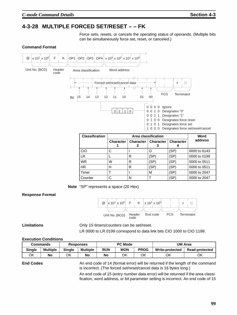
C-mode Command Details Section 4-3
4-3-28 MULTIPLE FORCED SET/RESET – – FKForce sets, resets, or cancels the operating status of operands. (Multiple bitscan be simultaneously force set, reset, or canceled.)
Command Format
Note “SP” represents a space (20 Hex).
Response Format
Limitations Only 15 timers/counters can be set/reset.
LR 0000 to LR 0199 correspond to data link bits CIO 1000 to CIO 1199.
Execution Conditions
End Codes An end code of 14 (format error) will be returned if the length of the commandis incorrect. (The forced set/reset/cancel data is 16 bytes long.)
An end code of 15 (entry number data error) will be returned if the area classi-fication, word address, or bit parameter setting is incorrect. An end code of 15
Classification Area classification WordaddressCharacter
1Character
2Character
3Character
4
CIO C I O (SP) 0000 to 6143
LR L R (SP) (SP) 0000 to 0199
WR W R (SP) (SP) 0000 to 0511
HR H R (SP) (SP) 0000 to 0511
Timer T I M (SP) 0000 to 2047
Counter C N T (SP) 0000 to 2047
*
@ F Kx 100x 101 x 103 x 102 x 101 x 100OP1 OP2 OP3 OP4
↵
15 14 13 12 11 10 01 00
Unit No. (BCD) Header code
Area classification Word address
Forced set/reset/cancel data
BitTerminatorFCS
0 0 0 0 Ignore0 0 1 0 Designates "0"0 0 1 1 Designates "1"0 1 0 0 Designates force reset0 1 0 1 Designates force set1 0 0 0 Designates force set/reset/cancel
3 2 1 0
@ F Kx 100x 101 x 161 x 160 ↵*
Unit No. (BCD) Header code
TerminatorFCSEnd code
Commands Responses PC Mode UM Area
Single Multiple Single Multiple RUN MON PROG Write-protected Read-protected
OK No OK No No OK OK OK OK
99

C-mode Command Details Section 4-3
will also be returned if the a data specification of 0 or 1 is used when a timeror counter is designated.
4-3-29 FORCED SET/RESET CANCEL – – KCCancels all forced set and forced reset bits (including those set by FORCEDSET, FORCED RESET, and MULTIPLE FORCED SET/RESET).
Command Format
Response Format
Execution Conditions
End Codes An end code of 14 (format error) will be returned if the length of the commandis incorrect. (The forced set/reset/cancel data can be 16 bytes long.)
End code (Hex) Contents
00 Normal completion
01 Not executable in RUN mode
13 FCS error
14 Format error
15 Entry number data error
18 Frame length error
21 Not executable due to CPU Unit CPU error.
@ K Cx 100x 101 ↵*
Unit No. (BCD) Header code
TerminatorFCS
@ K Cx 100x 101 x 161 x 160 ↵*
Unit No. (BCD) Header code
TerminatorFCSEnd code
Commands Responses PC Mode UM Area
Single Multiple Single Multiple RUN MON PROG Write-protected Read-protected
OK No OK No No OK OK OK OK
End code (Hex) Contents
00 Normal completion
01 Not executable in RUN mode
13 FCS error
14 Format error
15 Entry number data error
18 Frame length error
21 Not executable due to CPU Unit CPU error.
100

C-mode Command Details Section 4-3
4-3-30 PC MODEL READ – – MMReads the model code of the CPU Unit.
Command Format
Response Format
“Model code” indicates the model in two digits hexadecimal.
Execution Conditions
End Codes An end code of 14 (format error) will be returned if the length of the commandis incorrect.
@ M Mx 100x 101 ↵*
Unit No. (BCD) Header code
TerminatorFCS
Model code Model
30 CS/CJ
01 C250
02 C500
03 C120/C50
09 C250F
0A C500F
0B C120F
0E C2000
10 C1000H
11 C2000H/CQM1/CPM1
12 C20H/C28H/C40H, C200H, C200HS, C200HX/HG/HE (-ZE)
20 CV500
21 CV1000
22 CV2000
40 CVM1-CPU01-E
41 CVM1-CPU11-E
42 CVM1-CPU21-E
@ M Mx 100x 101 x 161 x 160 ↵*x 161 x 160
Unit No. (BCD) Header code
TerminatorFCSEnd code Model code
Commands Responses PC Mode UM Area
Single Multiple Single Multiple RUN MON PROG Write-protected Read-protected
OK No OK No OK OK OK OK OK
End code (Hex) Contents
00 Normal completion
13 FCS error
14 Format error
18 Frame length error
21 Not executable due to CPU Unit CPU error.
101

C-mode Command Details Section 4-3
4-3-31 TEST– – TSReturns, unaltered, one block of data transmitted from the host computer.
Command Format Specify any characters other than the carriage return.
Response Format The same characters specified in the command will be returned unaltered ifthe test is successful.
Limitations Between 0 and 122 characters can be sent.
If the command is correct, no end code will be returned.
Execution Conditions
End Codes An end code of 14 (format error) will be returned if a terminator is not receivedin the first frame.
4-3-32 PROGRAM READ – – RPReads the contents of the CPU Unit user’s program area in machine lan-guage. The contents are read as a block, from the beginning to the end.
Command Format
Response Format
Limitations The command cannot be executed if the UM Area is read-protected.
Data is read from the beginning of the UM Area to the maximum limit of theprogram area.
@ T Sx 100x 101 * ↵
Unit No. (BCD) Header code
Characters
122 characters max.
TerminatorFCS
@ T Sx 100x 101 * ↵
Unit No. (BCD) Header code
Characters
122 characters max.
TerminatorFCS
Commands Responses PC Mode UM Area
Single Multiple Single Multiple RUN MON PROG Write-protected Read-protected
OK No OK No OK OK OK OK OK
End code (Hex) Contents
13 FCS error
14 Format error
18 Frame length error
21 Not executable due to CPU Unit CPU error.
@ R Px 100x 101 ↵*
Unit No. (BCD) Header code
TerminatorFCS
@ R Px 100x 101 x 161 x 160 ↵*
Unit No. (BCD) Header code
End code Complete program TerminatorFCS
102

C-mode Command Details Section 4-3
The response’s first frame will contain 30 words of program data. The secondand later frames will contain 31 words except for the last frame, which willcontain up to 31 words.
The INITIALIZE and ABORT commands can be sent instead of the delimiterfor multiple responses for this command. If other commands are sent, they willbe treated as delimiters.
Execution Conditions
End Codes An end code of 14 (format error) will be returned if the length of the commandis incorrect.
4-3-33 PROGRAM WRITE – – WPWrites to the CPU Unit user’s program area the machine language programtransmitted from the host computer. The contents are written as a block, fromthe beginning.
Command Format
Response Format
Limitations The command cannot be executed while the UM Area is write-protected.
Data is written from the beginning of the UM Area to the maximum limit of theprogram area.
An error will not occur if the command attempts to write program data beyondthe maximum size of the program area.
The program data can be divided into multiple frames in units of 4 characters.
Execution Conditions
Commands Responses PC Mode UM Area
Single Multiple Single Multiple RUN MON PROG Write-protected Read-protected
OK No OK OK OK OK OK OK No
End code (Hex) Contents
00 Normal completion
13 FCS error
14 Format error
18 Frame length error
19 Not executable
21 Not executable due to CPU Unit CPU error.
23 User memory protected
@ W Px 100x 101 x 161 x 160 ↵*
Unit No. (BCD) Header code
Complete program TerminatorFCS
@ W Px 100x 101 x 161 x 160 ↵*
Unit No. (BCD) Header code
End code TerminatorFCS
Commands Responses PC Mode UM Area
Single Multiple Single Multiple RUN MON PROG Write-protected Read-protected
OK OK OK No No No OK No OK
103

C-mode Command Details Section 4-3
End Codes An end code of 14 (format error) will be returned if the length of the commandis incorrect (the total size of the program is not a multiple of 8 bytes) or the firstframe contains no program data.
An end code of 15 (entry number data error) will be returned if the specifiedwrite data is not hexadecimal.
4-3-34 I/O TABLE GENERATE – – MICorrects the registered I/O table to match the actual I/O table.
Command Format
Response Format
Limitations The write-protected end code for this command is different from that of theother commands.
Execution Conditions
End Codes An end code of 14 (format error) will be returned if the length of the commandis incorrect.
End code (Hex) Contents
00 Normal completion
01 Not executable in RUN mode
02 Not executable in MONITOR mode
13 FCS error
14 Format error
15 Entry number data error
18 Frame length error
19 Not executable
21 Not executable due to CPU Unit CPU error.
23 User memory protected
A3 Aborted due to FCS error in transmit data
A4 Aborted due to format error in transmit data
A5 Aborted due to entry number data error in transmit data
A8 Aborted due to frame length error in transmit data
@ M Ix 100x 101 ↵*
Unit No. (BCD) Header code
TerminatorFCS
@ M Ix 100x 101 x 161 x 160 ↵*
Unit No. (BCD) Header code
End code TerminatorFCS
Commands Responses PC Mode UM Area
Single Multiple Single Multiple RUN MON PROG Write-protected Read-protected
OK No OK No No No OK No OK
End code (Hex) Contents
00 Normal completion
01 Not executable in RUN mode
02 Not executable in MONITOR mode
03 UM write-protected
13 FCS error
104

C-mode Command Details Section 4-3
4-3-35 REGISTER I/O MEMORY – – QQMRPre-registers to the table all of the I/O memory area bits, words, and timers/counters that are to be read. The registered contents are retained until theyare overwritten or until the power is cut off, so they can be read by QQIR.(Refer to �������� !"�#$��� ���%�&�&�''#�.)
Command Format
Note “SP” represents a space (20 Hex).
Response Format
Limitations LR 0000 to LR 0199 correspond to data link bits CIO 1000 to CIO 1199.
14 Format error
18 Frame length error
19 Not executable
20 Could not create I/O table
21 Not executable due to CPU Unit CPU error.
End code (Hex) Contents
Classification Area classification Word address (BCD)Character
1Character
2Character
3Character
4
CIO C I O (SP) 0000 to 6143
LR L R (SP) (SP) 0000 to 0199
AR A R (SP) (SP) 0000 to 0959
HR H R (SP) (SP) 0000 to 0511
WR W R (SP) (SP) 0000 to 0511
Timer T I M (SP) 0000 to 2047
Counter C N T (SP) 0000 to 2047
DM D M (SP) (SP) 0000 to 9999
EM current bank E M (SP) (SP) 0000 to 9999
EM banks 0 to C E M 0 0 0000 to 9999
to
E M 0 C
@ Q Qx 100x 101 x 103 x 102 x 101 x 100M
x 103 x 102 x 101 x 100OP1 OP2 OP3 OP4 OP1 OP2 ↵*
Unit No. (BCD) Header code
TerminatorFCS
Area classification Word address Bit/word Data break
Word addressData break
R ,
,
Area classification Bit/word
Bit/word00 to 15: Bit designation (BCD)Word: Word data designation (ON/OFF data only when other than word is designated by T/C.)
@ Q Qx 100x 101 x 161 x 160M R ↵*
Unit No. (BCD) Header code End code TerminatorFCS
105

C-mode Command Details Section 4-3
The maximum number of items that can be registered is 128, and timer/counter word designation is counted as two items.
If all of the registered data is correct, it will be registered to the table.
EM can be read through the current bank or bank designation.
Bits and words can be specified in any order and they will be registered in theorder that they were specified.
The data can be divided into multiple frames.
Execution Conditions
End Codes An end code of 14 (format error) will be returned if the “,” data break betweentwo items is omitted. (The command will be considered correct if there is a “,”data break just before the FCS or at the beginning of a multiple-frame com-mand.)
An end code of 15 (entry number data error) will be returned if the area classi-fication, word address, or bit/word setting is out of range (including hexadeci-mal data).
4-3-36 READ I/O MEMORY – – QQIRReads the word and bit data, from multiple I/O memory areas, that was regis-tered with QQMR.
Command Format
Commands Responses PC Mode UM Area
Single Multiple Single Multiple RUN MON PROG Write-protected Read-protected
OK OK OK No OK OK OK OK OK
End code (Hex) Contents
00 Normal completion
13 FCS error
14 Format error
15 Entry number data error
18 Frame length error
19 Not executable
A3 Aborted due to FCS error in transmit data
A4 Aborted due to format error in transmit data
A5 Aborted due to entry number data error in transmit data
A8 Aborted due to frame length error in transmit data
@ Q Qx 100x 101 I R ↵*
Unit No. (BCD) Header code TerminatorFCS
106

C-mode Command Details Section 4-3
Response Format
Limitations The data is read in the same order in which it was registered with QQMR.
Execution Conditions
End Codes An end code of 14 (format error) will be returned if the length of the commandis incorrect.
An end code of 19 (not executable) will be returned if there is no registereddata.
4-3-37 ABORT – – XZAborts the Host Link command that is currently being processed, allowing thenext command to be received.
Command Format
Limitations Multiple responses to a command can be cancelled with this command.
An FCS code and terminator are required.
End Codes
The ABORT command does not receive a response.
End Codes There are no end codes with this command. (There is no response).
,
@ Q Qx 100x 101 x 161 x 160I R
x 163 x 162 x 161 x 160 ↵*
ON/OFF x 103 x 102 x 101 x 100
ON/OFF
Unit No. (BCD)
Header code End code Timer/counter word designation:ON: 1; OFF: 0 + word data (BCD)
Data break
Bit data ON/OFF
Word dataCIO, LR, AR, HR, WR, DM, EM and other word (Hex) data.
TerminatorFCS
, ,
,
Commands Responses PC Mode UM Area
Single Multiple Single Multiple RUN MON PROG Write-protected Read-protected
OK No OK OK OK OK OK OK OK
End code (Hex) Contents
00 Normal completion
13 FCS error
14 Format error
18 Frame length error
19 Not executable
21 Not executable due to CPU Unit CPU error.
@ X Zx 100x 101 ↵*
Unit No. (BCD) Header code
TerminatorFCS
107
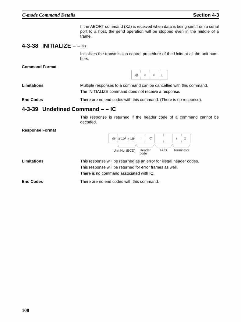
C-mode Command Details Section 4-3
If the ABORT command (XZ) is received when data is being sent from a serialport to a host, the send operation will be stopped even in the middle of aframe.
4-3-38 INITIALIZE – – ��Initializes the transmission control procedure of the Units at all the unit num-bers.
Command Format
Limitations Multiple responses to a command can be cancelled with this command.
The INITIALIZE command does not receive a response.
End Codes There are no end codes with this command. (There is no response).
4-3-39 Undefined Command – – ICThis response is returned if the header code of a command cannot bedecoded.
Response Format
Limitations This response will be returned as an error for illegal header codes.
This response will be returned for error frames as well.
There is no command associated with IC.
End Codes There are no end codes with this command.
↵@ **
@ I Cx 100x 101 ↵*
Unit No. (BCD) Header code
TerminatorFCS
108

109
SECTION 5FINS Commands
This section provides detailed descriptions of the FINS commands.
5-1 Command Lists . . . . . . . . . . . . . . . . . . . . . . . . . . . . . . . . . . . . . . . . . . . . . . . . 1105-1-1 FINS Commands . . . . . . . . . . . . . . . . . . . . . . . . . . . . . . . . . . . . . . . 1105-1-2 FINS Command Restrictions . . . . . . . . . . . . . . . . . . . . . . . . . . . . . . 1115-1-3 End Codes. . . . . . . . . . . . . . . . . . . . . . . . . . . . . . . . . . . . . . . . . . . . . 113
5-2 Designating Command Parameters . . . . . . . . . . . . . . . . . . . . . . . . . . . . . . . . . 1195-2-1 Designating I/O Memory (Variable) Area Addresses. . . . . . . . . . . . 1195-2-2 I/O Memory Address Designations . . . . . . . . . . . . . . . . . . . . . . . . . 122
5-3 FINS Commands. . . . . . . . . . . . . . . . . . . . . . . . . . . . . . . . . . . . . . . . . . . . . . . 1265-3-1 About this Section. . . . . . . . . . . . . . . . . . . . . . . . . . . . . . . . . . . . . . . 1265-3-2 MEMORY AREA READ: 01 01 . . . . . . . . . . . . . . . . . . . . . . . . . . . 1275-3-3 MEMORY AREA WRITE: 01 02 . . . . . . . . . . . . . . . . . . . . . . . . . . 1295-3-4 MEMORY AREA FILL: 01 03 . . . . . . . . . . . . . . . . . . . . . . . . . . . . 1305-3-5 MULTIPLE MEMORY AREA READ: 01 04 . . . . . . . . . . . . . . . . . 1315-3-6 MEMORY AREA TRANSFER: 01 05 . . . . . . . . . . . . . . . . . . . . . . 1335-3-7 PARAMETER AREA READ: 02 01 . . . . . . . . . . . . . . . . . . . . . . . . 1355-3-8 PARAMETER AREA WRITE: 02 02 . . . . . . . . . . . . . . . . . . . . . . . 1365-3-9 PARAMETER AREA CLEAR: 02 03 . . . . . . . . . . . . . . . . . . . . . . . 1385-3-10 PROGRAM AREA READ: 03 06 . . . . . . . . . . . . . . . . . . . . . . . . . . 1395-3-11 PROGRAM AREA WRITE: 03 07 . . . . . . . . . . . . . . . . . . . . . . . . . 1405-3-12 PROGRAM AREA CLEAR: 03 08 . . . . . . . . . . . . . . . . . . . . . . . . . 1415-3-13 RUN: 04 01. . . . . . . . . . . . . . . . . . . . . . . . . . . . . . . . . . . . . . . . . . . . 1425-3-14 STOP: 04 02 . . . . . . . . . . . . . . . . . . . . . . . . . . . . . . . . . . . . . . . . . . . 1435-3-15 CPU UNIT DATA READ: 05 01 . . . . . . . . . . . . . . . . . . . . . . . . . . . 1445-3-16 CONNECTION DATA READ: 05 02 . . . . . . . . . . . . . . . . . . . . . . . 1465-3-17 CPU UNIT STATUS READ: 06 01 . . . . . . . . . . . . . . . . . . . . . . . . . 1475-3-18 CYCLE TIME READ: 06 20 . . . . . . . . . . . . . . . . . . . . . . . . . . . . . . 1505-3-19 CLOCK READ: 07 01 . . . . . . . . . . . . . . . . . . . . . . . . . . . . . . . . . . . 1515-3-20 CLOCK WRITE: 07 02 . . . . . . . . . . . . . . . . . . . . . . . . . . . . . . . . . . 1515-3-21 MESSAGE READ: 09 20. . . . . . . . . . . . . . . . . . . . . . . . . . . . . . . . . 1525-3-22 MESSAGE CLEAR: 09 20. . . . . . . . . . . . . . . . . . . . . . . . . . . . . . . . 1545-3-23 FAL/FALS READ: 09 20 . . . . . . . . . . . . . . . . . . . . . . . . . . . . . . . . . 1555-3-24 ACCESS RIGHT ACQUIRE: 0C 01 . . . . . . . . . . . . . . . . . . . . . . . . 1565-3-25 ACCESS RIGHT FORCED ACQUIRE: 0C 02 . . . . . . . . . . . . . . . . 1585-3-26 ACCESS RIGHT RELEASE: 0C 03 . . . . . . . . . . . . . . . . . . . . . . . . 1605-3-27 ERROR CLEAR: 21 01 . . . . . . . . . . . . . . . . . . . . . . . . . . . . . . . . . . 1605-3-28 ERROR LOG READ: 21 02. . . . . . . . . . . . . . . . . . . . . . . . . . . . . . . 1625-3-29 ERROR LOG CLEAR: 21 03. . . . . . . . . . . . . . . . . . . . . . . . . . . . . . 1635-3-30 FILE NAME READ: 22 01 . . . . . . . . . . . . . . . . . . . . . . . . . . . . . . . 1645-3-31 SINGLE FILE READ: 22 02 . . . . . . . . . . . . . . . . . . . . . . . . . . . . . . 1665-3-32 SINGLE FILE WRITE: 22 03 . . . . . . . . . . . . . . . . . . . . . . . . . . . . . 1675-3-33 FILE MEMORY FORMAT: 22 04 . . . . . . . . . . . . . . . . . . . . . . . . . . 1695-3-34 FILE DELETE: 22 05. . . . . . . . . . . . . . . . . . . . . . . . . . . . . . . . . . . . 1705-3-35 FILE COPY: 22 07 . . . . . . . . . . . . . . . . . . . . . . . . . . . . . . . . . . . . . . 1715-3-36 FILE NAME CHANGE: 22 08 . . . . . . . . . . . . . . . . . . . . . . . . . . . . 1725-3-37 MEMORY AREA–FILE TRANSFER: 22 0A. . . . . . . . . . . . . . . . . 1735-3-38 PARAMETER AREA–FILE TRANSFER: 22 0B. . . . . . . . . . . . . . 1745-3-39 PROGRAM AREA–FILE TRANSFER: 22 0C . . . . . . . . . . . . . . . . 1765-3-40 CREATE/DELETE DIRECTORY: 22 15. . . . . . . . . . . . . . . . . . . . . 1785-3-41 FORCED SET/RESET: 23 01 . . . . . . . . . . . . . . . . . . . . . . . . . . . . . 1795-3-42 FORCED SET/RESET CANCEL: 23 02 . . . . . . . . . . . . . . . . . . . . . 180

Command Lists Section 5-1
5-1 Command Lists
5-1-1 FINS Commands
The following table lists the FINS commands.
Type Command code
Name Function
MR SR
I/O memory area access
01 01 MEMORY AREA READ Reads the contents of consecutive I/O memory area words.
01 02 MEMORY AREA WRITE Writes the contents of consecutive I/O memory area words.
01 03 MEMORY AREA FILL Writes the same data to the specified range of I/O memory area words.
01 04 MULTIPLE MEMORY AREA READ Reads the contents of specified non-consecutive I/O memory area words.
01 05 MEMORY AREA TRANSFER Copies the contents of consecutive I/O memory area words to another I/O memory area.
Parameter area access
02 01 PARAMETER AREA READ Reads the contents of consecutive parameter area words.
02 02 PARAMETER AREA WRITE Writes the contents of consecutive parameter area words.
02 03 PARAMETER AREA FILL (CLEAR) Writes the same data to the specified range of parameter area words.
Program area access
03 06 PROGRAM AREA READ Reads the UM (User Memory) area.
03 07 PROGRAM AREA WRITE Writes to the UM (User Memory) area.
03 08 PROGRAM AREA CLEAR Clears the UM (User Memory) area.
Operating mode changes
04 01 RUN Changes the CPU Unit’s operating mode to RUN or MONITOR.
04 02 STOP Changes the CPU Unit’s operating mode to PROGRAM.
Machine configura-tion reading
05 01 CPU UNIT DATA READ Reads CPU Unit data.
05 02 CONNECTION DATA READ Reads the model numbers of the device corresponding to addresses.
Status reading 06 01 CPU UNIT STATUS READ Reads the status of the CPU Unit.
06 20 CYCLE TIME READ Reads the maximum, minimum, and average cycle time.
Time data access 07 01 CLOCK READ Reads the present year, month, date, minute, second, and day of the week.
07 02 CLOCK WRITE Changes the present year, month, date, minute, second, or day of the week.
Message display 09 20 MESSAGE READ/CLEAR Reads and clears messages, and reads FAL/FALS messages.
Access rights 0C 01 ACCESS RIGHT ACQUIRE Acquires the access right as long as no other device holds it.
0C 02 ACCESS RIGHT FORCED ACQUIRE Acquires the access right even if another device already holds it.
0C 03 ACCESS RIGHT RELEASE Releases the access right that has been acquired.
Error log 21 01 ERROR CLEAR Clears errors or error messages.
21 02 ERROR LOG READ Reads the error log.
21 03 ERROR LOG POINTER CLEAR Clears the error log pointer.
110

Command Lists Section 5-1
5-1-2 FINS Command Restrictions
File memory 22 01 FILE NAME READ Reads file memory data.
22 02 SINGLE FILE READ Reads a specified length of file data from a specified position within a single file.
22 03 SINGLE FILE WRITE Writes a specified length of file data from a specified position within a single file.
22 04 FILE MEMORY FORMAT Formats (initializes) the file memory.
22 05 FILE DELETE Deletes specified files stored in the file memory.
22 07 FILE COPY Copies files from one file memory to another file memory in the same system.
22 08 FILE NAME CHANGE Changes a file name.
22 0A MEMORY AREA–FILE TRANSFER Transfers or compares data between the I/O memory area and the file memory.
22 0B PARAMETER AREA–FILE TRANSFER Transfers or compares data between the parameter area and the file memory.
22 0C PROGRAM AREA–FILE TRANSFER Transfers or compares data between the UM (User Memory) area and the file memory.
22 15 CREATE/DELETE DIRECTORY Creates or deletes a directory.
Debugging 23 01 FORCED SET/RESET Force-sets or force-resets bits, or releases force-set status.
23 02 FORCED SET/RESET CANCEL Cancels all bits that have been force-set
or force-reset.
Type Command code
Name PC status
RUN mode
MONI-TOR
mode
PRO-GRAM mode
Access right
UM read protec-
tion
DIP switch
UM pro-tection
MR SR
I/O memory area access
01 01 MEMORY AREA READ OK OK OK OK OK OK
02 MEMORY AREA WRITE OK OK OK OK OK OK
03 MEMORY AREA FILL OK OK OK OK OK OK
04 MULTIPLE MEMORY AREA READ
OK OK OK OK OK OK
05 MEMORY AREA TRANSFER
OK OK OK OK OK OK
Parameter area access
02 01 PARAMETER AREA READ
OK OK OK OK OK OK
02 PARAMETER AREA WRITE
OK OK OK Disabled OK Disabled
03 PARAMETER AREA CLEAR
OK OK OK Disabled OK Disabled
Program area access
03 06 PROGRAM AREA READ
OK OK OK OK Disabled OK
07 PROGRAM AREA WRITE
Disabled Disabled OK Disabled OK Disabled
08 PROGRAM AREA CLEAR
Disabled Disabled OK Disabled OK Disabled
Type Command code
Name Function
MR SR
111

Command Lists Section 5-1
Note 1. File-to-memory area transfers are not possible
2. File-to-program area transfers are not possible
3. Program area-to-file transfers are possible
Operating mode changes
04 01 RUN OK OK OK Disabled OK OK
02 STOP OK OK OK Disabled OK OK
Machine configuration reading
05 01 CPU UNIT DATA READ OK OK OK OK OK OK
02 CONNECTION DATA READ
OK OK OK OK OK OK
Statusreading
06 01 CPU UNIT STATUS READ
OK OK OK OK OK OK
20 CYCLE TIME READ OK OK Disabled OK OK OK
Time data access
07 01 CLOCK READ OK OK OK OK OK OK
02 CLOCK WRITE OK OK OK Disabled OK OK
Message display
09 20 MESSAGE READ/CLEAR
OK OK OK Disabled (MES-SAGE CLEAR only)
OK OK
Access rights 0C 01 ACCESS RIGHT ACQUIRE
OK OK OK Disabled OK OK
02 ACCESS RIGHT FORCED ACQUIRE
OK OK OK OK OK OK
03 ACCESS RIGHT RELEASE
OK OK OK OK OK OK
Error log 21 01 ERROR CLEAR OK OK OK Disabled OK OK
02 ERROR LOG READ OK OK OK OK OK OK
03 ERROR LOG CLEAR OK OK OK OK OK OK
File memory 22 01 FILE NAME READ OK OK OK OK OK OK
02 SINGLE FILE READ OK OK OK OK OK OK
03 SINGLE FILE WRITE OK OK OK Disabled OK OK
04 FILE MEMORY FORMAT
OK OK OK Disabled OK OK
05 FILE DELETE OK OK OK Disabled OK OK
07 FILE COPY OK OK OK Disabled OK OK
08 FILE NAME CHANGE OK OK OK Disabled OK OK
0A MEMORY AREA–FILE TRANSFER
OK OK OK Disabled OK OK
0B PARAMETER AREA–FILE TRANSFER
OK (note 1)
OK (note 1)
OK Disabled OK OK (note 1)
0C PROGRAM AREA–FILE TRANSFER
OK (note 2)
OK (note 2)
OK Disabled OK Disabled (note 3)
15 CREATE/DELETE DIRECTORY
OK OK OK Disabled OK OK
Debugging 23 01 FORCED SET/RESET Disabled OK OK OK OK OK
02 FORCED SET/RESET CANCEL
Disabled OK OK OK OK OK
Type Command code
Name PC status
RUN mode
MONI-TOR
mode
PRO-GRAM mode
Access right
UM read protec-
tion
DIP switch
UM pro-tection
MR SR
112

Command Lists Section 5-1
5-1-3 End CodesThe following table lists the main codes and the sub-codes, which combine toform the end code (response code) returned for a FINS command. The prob-able cause and corrections for each error code are also given.
Depending on the command, the destination code will sometimes make arequest of another node on a network. The other node is referred to as thethird node.
Main code Subcode Check point Probable cause Correction
00: Normal completion
00: Normal completion
--- --- ---
01: Service canceled
--- Service was cancelled. Check the capacity of the destina-tion area in the third node.
Data link status Service was cancelled. Check the status of the data link.
01: Local node error
01: Local node not in network
Network status of local node
Local node is not participat-ing in the network.
Connect the node to the network.
02: Token timeout
Maximum node address
Token doesn’t arrive. Set the local node to within the maximum node address.
03: Retries failed
--- Send was not possible during the specified number of retries.
Execute a communications test between the nodes and re-examine the system environment if it fails.
04: Too many send frames
Number of enabled send frames
Cannot send because maxi-mum number of event frames exceeded.
Check event execution on the net-work and reduce the number of events per cycle.Increase the maximum number of event frames.
05: Node address range error
Node address Node address setting error occurred.
Check the settings of the rotary switches to be sure that the address is within range and that each address is set only once in the same network.
06: Node address duplication
Node addresses The same node address has been set twice in the same network.
Change the address of one of the nodes with the same address.
02: Destination node error
01: Destination node not in net-work
INS indicator on Unit
The destination node is not in the network.
Add the destination node to the net-work.
02: Unit miss-ing
Instruction control data
There is no Unit with the specified unit address.
Check the destination unit address.
03: Third node missing
Instruction control data
The third node does not exist. Check the unit address of the third node. Check the node address of the third node in the send data for CMND(490).
Command data Broadcasting was specified. Specify only one node for the third node.
04: Destination node busy
--- The destination node is busy. Increase the number of retries or review the system so that the destination node does not receive so many messages.
05: Response timeout
--- The message was destroyed by noise.
Increase the number of retries or test communications between nodes to see if there is too much noise.
Instruction control data
The response monitor time is too short.
Increase the length of the response monitor time.
Error history The send/receive frame was discarded.
Take appropriate measures based on the error history.
113

Command Lists Section 5-1
03: Controller error
01: Communi-cations control-ler error
Unit/Board indicators
An error occurred in the communications controller.
Take appropriate measures based on the operation manuals for the related Units/Boards.
02: CPU Unit error
CPU Unit indicators at destination node
A CPU error occurred in the destination CPU Unit.
Clear the error from the CPU Unit based on its operation manuals.
03: Controller error
Board indicators A response was not returned because an error occurred in the Board.
Check network communications status and restart the Board. If the problem persists, replace the Board.
04: Unit number error
Unit number The unit number was set incorrectly.
Set the rotary switches correctly, being sure the unit numbers are within range and that each number is used only once.
04: Service unsupported
01: Undefined command
Command code The Unit/Board does not sup-port the specified command code.
Check the command code.
02: Not supported by model/version
Unit model and version
The command cannot be executed because the model or version is incorrect.
Check the model number and version.
05: Routing table error
01: Destination address setting error
Routing table The destination network or node address is not set in the routing tables.
Register the destination network and node in the routing tables.
02: No routing tables
Routing table Relaying is not possible because there are no routing tables.
Set routing tables in the source node, designation node, and relay nodes.
03: Routing table error
Routing table There is an error in the routing tables.
Set the routing tables correctly.
04: Too many relays
Network configuration
An attempt was made to send to a network that was over 3 networks away
Reconstruct the networks or change the routing tables so that commands are sent within a range of 3 networks or less.
10: Command format error
01: Command too long
Command data The command is longer than the maximum permissible length.
Check the command format and correct the command data.
02: Command too short
Command data The command is shorter than the minimum permissible length.
Check the command format and correct the command data.
03: Elements/ data don’t match
Command data The designated number of elements differs from the number of write data items.
Check the number of elements and set data for each element.
04: Command format error
Command data An incorrect format was used.
Check the command format and correct the command data.
05: Header error
Routing table Either the relay table in the local node or the local net-work table in the relay node is incorrect.
Set the routing tables correctly.
Main code Subcode Check point Probable cause Correction
114

Command Lists Section 5-1
11: Parameter error
01: Area classi-fication missing
Memory area code in command data
The specified word does not exist in the memory area or there is no EM Area.
Check the memory areas and parameter codes in the command and correct the command data.
02: Access size error
Access size specification in command data
The access size specifica-tion is incorrect or an odd word address is specified.
Check the memory areas and access size and correct the access size.
03: Address range error
Starting address in command data
The start address in com-mand process is beyond the accessible area.
Check the area being processed and set the correct range.
04: Address range exceeded
Starting address and number of elements in command data
The end address in com-mand process is beyond the accessible area.
Check the area being processed and set the correct range.
Data link tables The total number of words is beyond the limit.
Correct the data link tables.
06: Program missing
Program number in command data
FFFF Hex was not specified. Specify FFFF Hex.
09: Relational error
Command data A large–small relationship in the elements in the command data is incorrect.
Check the command data and correct the relationship between the elements.
Data link table A node not set in the common link parameters is set as a refresh parameter.
Correct the data link tables.
0A: Duplicate data access
I/O access in CPU Unit
Differential monitoring was specified during data tracing or data tracing was specified during differential monitoring.
Abort the current process or wait until it ends before executing the command.
Data link tables The same node address is specified more than once.
Correct the data link tables.
0B: Response too long
Number of ele-ments in com-mand data
The response format is longer than the maximum permissible length.
Check the command format and correct the number of elements.
0C: Parameter error
Parameters in command data
There is an error in one of the parameter settings.
Check the command data and correct the parameters.
Data link table file
There is an error in the file. Check the contents of the file.
20: Read not possible
02: Protected --- The program area is pro-tected.
Release protection from a Program-ming Device and then execute the command.
03: Table miss-ing
Table A table has not been regis-tered.
Register a table.
There is an error in the table. Correct the table.
04: Data missing
--- The search data does not exist.
---
05: Program missing
Program num-ber in command data
A non-existing program number has been specified.
Check the program numbers and specify a valid one.
06: File missing File name and file device
The file does not exist at the specified file device.
Check the path and file name, and correct them.
07: Data mismatch
Contents of memory being compared
A data being compared is not the same.
Check memory contents and use the correct data.
--- A file read operation failed. Check the contents of the file.
Main code Subcode Check point Probable cause Correction
115

Command Lists Section 5-1
21: Write not possible
01: Read-only --- The specified area is read-only.
If the area is protected using a switch setting, release protection and then execute the command. If the area is permanently read-only, the command cannot be executed.
02: Protected
Cannot write data link table
--- The program area is protected.
Release protection from a Programming Device and then execute the command.
PC Setup Writing is not possible because automatic data link table generation has been specified.
Change the PC Setup so that the data link tables can be manually written.
03: Cannot register
Number of files in file device
The file cannot be created because the limit has been exceeded.
Delete any unnecessary files or create more file memory.
Number of files open
The maximum number of files has already been opened for the system limit.
Close one or more files and then execute the command.
05: Program missing
Program number in command data
A non-existing program number has been specified.
Check the program numbers and specify a valid one.
06: File missing File name The file does not exist at the specified file device.
Correct the file name and then execute the command.
07: File name already exists
File name A file with the same name already exists in the specified file device.
Change the name of the file being written and then execute the command.
08: Cannot change
Contents of memory being changed
The change cannot be made because doing so would create a problem.
---
22: Not execut-able in current mode
01: Not possi-ble during execution
--- The mode is incorrect. Check the mode.
Data link status The data link is operating. Check the status of the data links.
02: Not possible while running
--- The mode is incorrect. Check the mode.
Data link status The data links are active. Check the status of the data links.
03: Wrong PC mode
--- The PC is in PROGRAM mode.
Check the modes of the PC and computer.
04: Wrong PC mode
--- The PC is in DEBUG mode. Check the modes of the PC and computer.
05: Wrong PC mode
--- The PC is in MONITOR mode.
Check the modes of the PC and computer.
06: Wrong PC mode
--- The PC is in RUN mode. Check the modes of the PC and computer.
07: Specified node not polling node
--- The specified node is not the polling node.
Check node functioning as the polling node for the network.
08: Step cannot be exe-cuted
--- The mode is incorrect. Check step status.
23: No such device
01: File device missing
Unit configuration
The specified memory does not exist as a file device.
Mount memory or format EM as file memory.
02: Memory missing
--- There is no file memory. Check the file memory to see if it is mounted.
03: Clock missing
--- There is no clock. Check the model.
24: Cannot start/stop
01: Table missing
Data link tables The data link tables have not been registered or they contain an error.
Set the data link tables.
Main code Subcode Check point Probable cause Correction
116

Command Lists Section 5-1
25: Unit error 02: Memory error
Contents of memory being processed
The contents of memory contains an error.
Transfer the correct contents to memory.
03: I/O setting error
I/O Unit configuration
The registered I/O tables do not agree with the actual I/O configuration.
Correct the I/O tables or the I/O configuration.
04: Too many I/O points
Number of I/O in registered I/O tables
There are too many I/O points and remote I/O points registered.
Change the registered I/O table so that it is within the limit.
05: CPU bus error
CPU bus line An error occurred in data transfer between the CPU and a CPU Bus Unit.
Check Units, Boards, and cables to be sure they are connected cor-rectly and then execute the ERROR CLEAR command.
06: I/O duplication
Rack numbers, Unit numbers, and I/O addresses in PC Setup
The same number/address was set more than once.
Check the PC Setup and correct the numbers/addresses so that each is used only once.
07: I/O bus error
I/O bus line An error occurred in data transfer between the CPU and an I/O Unit.
Check Units, Boards, and cables to be sure they are connected cor-rectly and then execute the ERROR CLEAR command.
09: SYSMAC BUS/2 error
SYSMAC BUS/2 transmission path
An error occurred in data transfer on the SYSMAC BUS/2 line.
Check Units, Boards, and cables to be sure they are connected cor-rectly and then execute the ERROR CLEAR command.
0A: CPU Bus Unit error
CPU Bus Unit transmission path
An error occurred in data transfer for a CPU Bus Unit.
Check Units, Boards, and cables to be sure they are connected cor-rectly and then execute the ERROR CLEAR command.
0D: SYSMAC BUS No. duplication
Word settings The same word is allocated more than once.
Check the I/O tables and correct the allocations.
0F: Memory error
Status of mem-ory being processed
A memory error has occurred in internal memory, a mem-ory card, or EM file memory.
For internal memory, write the cor-rect data and then execute the com-mand.
For a memory card or EM file mem-ory, the file data has been destroyed. Execute the FILE MEM-ORY FORMAT command.If the problem persists, replace the memory.
10: SYSMAC BUS termina-tor missing
--- Terminators have not been set.
Set the terminators correctly.
Main code Subcode Check point Probable cause Correction
117

Command Lists Section 5-1
Note In addition to the above end codes, there are also three flags provided in theend code, i.e., bits 6, 7, and 15. If bit 15 is ON, an error has occurred in a network relay operation.If bit 6 or 7 is ON, and error has occurred in the destination CPU Unit. If thisoccurs, refer to the operation manuals for the CPU Unit where the error
26: Command error
01: No protec-tion
Command protection for program area
The specified area is not protected.
An attempt was made to clear protection on an area that is not protected, i.e., there is no reason to clear protection.
02: Incorrect password
--- An incorrect password has been specified.
Specify the correct password.
04: Protected --- The specified area is protected.
Clear protection from a Programming Device and then execute the command.
Number of com-mands being executed
The node receiving the command is already process-ing 5 commands.
Wait for current processing to end or force the end of a current process and then execute the command.
05: Service already executing
--- The service is being executed.
Wait for the service to end or force the end of the service and then exe-cute the command.
06: Service stopped
--- The service is not being executed.
If necessary, start the service.
07: No execution right
LNK indicator on Unit/Board
The right to execute the service has not been obtained.
The local node is not in the data link. Execute the command from a node that is participating in the data link.
--- A response was not returned because a buffer error occurred.
Restart the Board. If the problem persists, replace the Board.
08: Settings not complete
Settings required before execution
The settings required before executing the service have not been made.
Make the required settings.
09: Necessary items not set
Command data The required elements have not been set in the command data.
Check the command format and set the required elements in the command data.
0A: Number already defined
Action numbers and transition numbers of pro-gram in program area
The specified action/ transi-tion number has already been registered in a previous program.
Check the action/transition numbers to ones that are not being used and then execute the command.
0B: Error will not clear
Cause of error being cleared
The cause of the error has not been removed.
Remove the cause of the error and then execute ERROR CLEAR.
30: Access right error
01: No access right
--- The access right is held by another device. (Online edit-ing is being executed from another node or ACCESS RIGHT ACQUIRE or ACCESS RIGHT FORCE ACQUIRE has been executed by another node.)
Wait until the access right is released and then execute the command.ACCESS RIGHT ACQUIRE or ACCESS RIGHT FORCE ACQUIRE can be executed to obtain the access right, but this may adversely affect processing by the node that previously held the access right.
40: Abort 01: Service aborted
--- Service was aborted with ABORT command.
---
Main code Subcode Check point Probable cause Correction
118

Designating Command Parameters Section 5-2
occurred and remove the cause of the error.The contents of the end code are shown in the following diagram.
Handling Network Relay Errors
SEND(090) and RECV(098) Check the path the command took using the routing tables. Check the endcode and take appropriate measures for the relay node where the erroroccurred.
CMND(490) The location of the relay error can be determined by using the data returnedas the response data for the instruction, as shown in the following diagram.Use this information to determine the node where the error occurred and takeappropriate measures
5-2 Designating Command Parameters
5-2-1 Designating I/O Memory (Variable) Area AddressesWhen reading from and writing to the I/O memory (variable) area, designate I/O memory area addresses as described below.
I/O memory designation involves the designation of the memory area codeand the address within the memory area code.
• Memory area codes are designated in one byte (two digits hexadecimal),as shown in the table in 5-2-2 I/O Memory Address Designations.
BitMain code Sub-code
1: Fatal CPU Unit error 1: Non-fatal CPU Unit error1: Network relay error (See following section.)
BitMain code Sub-code
1: Fatal CPU Unit error 1: Non-fatal CPU Unit error
1: Network relay error (See following section.)
BitD (First Re-sponse Word)
Command code
D+1
BitD+2 Error network address Error node address
Error network address: 00 to 7F (0 to 127)Error Node Address
Ethernet: 01 to 7E (1 to 128)SYSMAC NET: 01 to 7E (1 to 126)Controller Link: 01 to 20 (1 to 32)SYSMAC LINK: 01 to 3E (1 to 62)
119

Designating Command Parameters Section 5-2
• Addresses within memory area codes consist of a total of three bytes (sixdigits hexadecimal). Of these, two bytes (four digits hexadecimal) desig-nate the word and one byte (two digits hexadecimal) designates the bit.
Example: I/O memory readingBit 13 of CIO 0010, i.e., CIO 001013, is read.
Example: Reading W005
Element Data Configurations
Bit DesignationsWhen bits are designated, each bit is considered a single element. The datafor the element is expressed in one byte (ON: 01 Hex; OFF: 00 Hex). Whendata is written, this byte is transmitted. When data is read, this byte isreturned.
I/O memory address designation
Memory area code Address within I/O memory area designation
Word Bit
4 bytes (8 digits hexa-decimal)
� 1 byte (2 digits Hex) 2 bytes (4 digits Hex) 1 byte (2 digits Hex)
Memory area code + word + bit, in order
Set by classification (CIO, WR, etc.).Note: Also possible with forced status.
From 0000 Hex (Upper limit depends on memory area code.)
00 to 0F HexNote: Always 00 Hex for word address and Timer/Counter Com-pletion Flags.
ExampleBit 13 of CIO 0010: 30000A0D Hex
ExampleCIO: 30 Hex
Example0010: 000A in hexa-decimal
ExampleBit 13: 0D in hexadec-imal
Command code
I/O memory area designation (Area: CIO, Data type: Bit)Read address
Command code
I/O memory designation (Area: WR, Data type: Word)Read address
01 01 B1 0D 05 00
00 Hex: OFF01 Hex: ON
120

Designating Command Parameters Section 5-2
Bit Data with Forced StatusWhen bits are designated, each bit is considered as one element.
The data for each element is expressed in one byte (8 bits). Bit 00 indicatesthe specified bit data, and bit 01 indicates the forced status, When reading,this one byte is returned.
Word DesignationsWhen words are designated, each word is considered a single element. Thedata for the element is expressed in two bytes. Bits 0 to 15 correspond to bits0 to 15 of each word. When data is written, these two bytes are transmitted foreach word. When data is read, these two bytes are returned.
Word Data With Forced Status Data, Present Value (4 Bytes)
Current EM Bank Number (2 Bytes)
Bit 000: OFF1: ON
Bit 010: No forced status1: Forced status
Bits 0 to 7
Bits 8 to 15
Word data, PV bits 0 to 7 (4th byte)
Word data, PV bits 8 to 15 (3rd byte)
Word data, PV bits 0 to 7 forced status (2nd byte)
Word data, PV bits 8 to 15 forced status (1st byte)
0: Not forced1: Forced
Bits 0 to 7 (2nd byte)
Bits 8 to 15 (1st byte)
Bit 15 0: EM not used or all banks converted to file memory.
1: EM used.
Bits 0 to 14: Current bank number
121
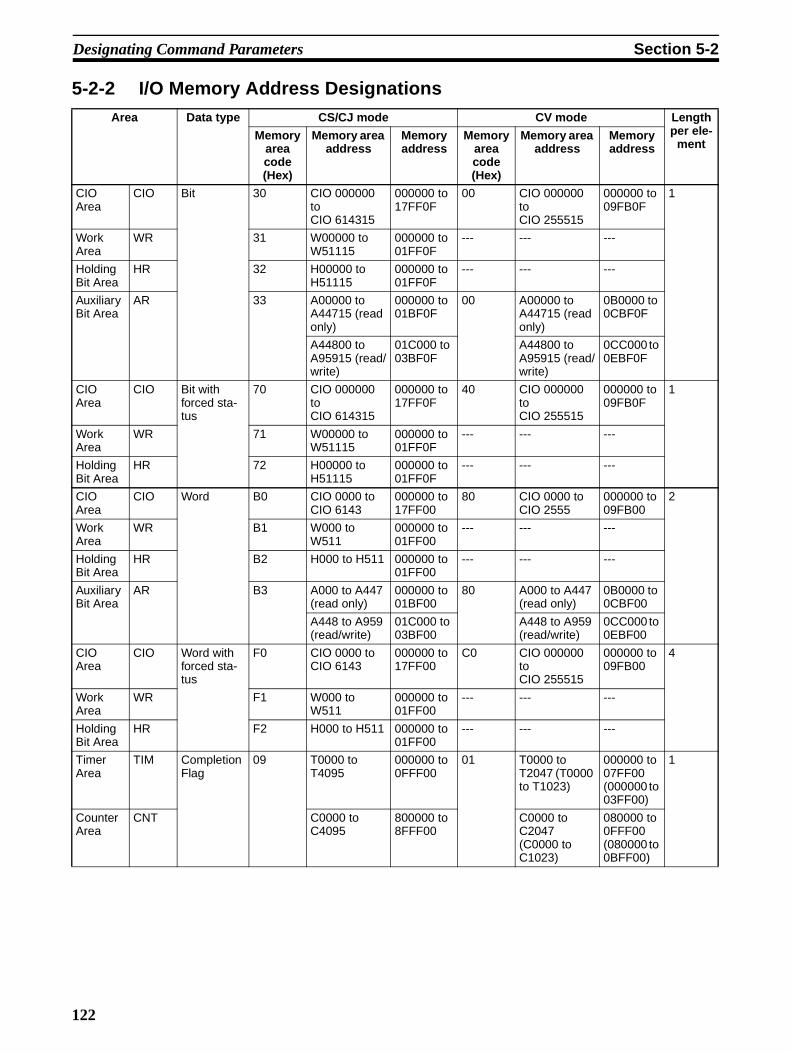
Designating Command Parameters Section 5-2
5-2-2 I/O Memory Address DesignationsArea Data type CS/CJ mode CV mode Length
per ele-ment
Memory area code (Hex)
Memory area address
Memory address
Memory area code (Hex)
Memory area address
Memory address
CIO Area
CIO Bit 30 CIO 000000 to CIO 614315
000000 to 17FF0F
00 CIO 000000 to CIO 255515
000000 to 09FB0F
1
Work Area
WR 31 W00000 to W51115
000000 to 01FF0F
--- --- ---
Holding Bit Area
HR 32 H00000 to H51115
000000 to 01FF0F
--- --- ---
Auxiliary Bit Area
AR 33 A00000 to A44715 (read only)
000000 to 01BF0F
00 A00000 to A44715 (read only)
0B0000 to 0CBF0F
A44800 to A95915 (read/write)
01C000 to 03BF0F
A44800 to A95915 (read/write)
0CC000 to 0EBF0F
CIO Area
CIO Bit with forced sta-tus
70 CIO 000000 to CIO 614315
000000 to 17FF0F
40 CIO 000000 to CIO 255515
000000 to 09FB0F
1
Work Area
WR 71 W00000 to W51115
000000 to 01FF0F
--- --- ---
Holding Bit Area
HR 72 H00000 to H51115
000000 to 01FF0F
--- --- ---
CIO Area
CIO Word B0 CIO 0000 to CIO 6143
000000 to 17FF00
80 CIO 0000 to CIO 2555
000000 to 09FB00
2
Work Area
WR B1 W000 to W511
000000 to 01FF00
--- --- ---
Holding Bit Area
HR B2 H000 to H511 000000 to 01FF00
--- --- ---
Auxiliary Bit Area
AR B3 A000 to A447 (read only)
000000 to 01BF00
80 A000 to A447 (read only)
0B0000 to 0CBF00
A448 to A959 (read/write)
01C000 to 03BF00
A448 to A959 (read/write)
0CC000 to 0EBF00
CIO Area
CIO Word with forced sta-tus
F0 CIO 0000 to CIO 6143
000000 to 17FF00
C0 CIO 000000 to CIO 255515
000000 to 09FB00
4
Work Area
WR F1 W000 to W511
000000 to 01FF00
--- --- ---
Holding Bit Area
HR F2 H000 to H511 000000 to 01FF00
--- --- ---
Timer Area
TIM Completion Flag
09 T0000 to T4095
000000 to 0FFF00
01 T0000 to T2047 (T0000 to T1023)
000000 to 07FF00 (000000 to 03FF00)
1
Counter Area
CNT C0000 to C4095
800000 to 8FFF00
C0000 to C2047 (C0000 to C1023)
080000 to 0FFF00 (080000 to 0BFF00)
122

Designating Command Parameters Section 5-2
Timer Area
TIM Completion Flag with forced sta-tus
49 T0000 to T4095
000000 to 0FFF00
41 T0000 to T2047 (T0000 to T1023)
000000 to 07FF00 (000000 to 03FF00)
1
Counter Area
CNT C0000 to C4095
800000 to 8FFF00
C0000 to C2047 (C0000 to C1023)
080000 to 0FFF00 (080000 to 0BFF00)
Timer Area
TIM PV 89 T0000 to T4095
000000 to 0FFF00
81 T0000 to T2047 (T0000 to T1023)
000000 to 07FF00 (000000 to 03FF00)
2
Counter Area
CNT C0000 to C4095
800000 to 8FFF00
C0000 to C2047 (C0000 to C1023)
080000 to 0FFF00 (080000 to 0BFF00)
DM Area DM Bit 02 D000000 to D3276715
000000 to 7FFF0F
--- --- --- 1
DM Word 82 D00000 to D32767
000000 to 7FFF00
82 D00000 to D32767
000000 to 7FFF00
2
EM Area EM (Bank 0 to C)
Bit 20 to 2C E0_0000000 to E0_3276715to
EC_0000000 to EC_3276715
000000 to 7FFF0F
--- --- --- 1
EM (Bank 0 to C)
Word A0 to AC E0_00000 to E0_32767
toEC_00000 to EC_32767
000000 to 7FFF00
to000000 to 7FFF00
90 to 97 E0_00000 to E0_32767
toE7_00000 to E7_32767
000000 to 7FFF00
to000000 to 7FFF00
2
EM (Cur-rent bank)
Word 98 E00000 to E32767
000000 to 7FFF00
98 E00000 to E32767
000000 to 7FFF00
2
EM (Cur-rent bank No.)
EM (Current bank No.)
BC --- 0F0000 9C --- 000600 2
Task Flag
TK Bit 06 TK0000 to TK0031
000000 to 001F00
--- --- --- 1
TK Status 46 TK0000 to TK0031
000000 to 001F00
--- --- --- 1
Index Register
IR PV DC IR00 to IR15 010000 to 010F00
--- --- --- 4
Data Register
DR PV BC DR00 to DR15
020000 to 020F00
9C DR0 to DR2 000300 to 000500
2
Area Data type CS/CJ mode CV mode Length per ele-
mentMemory
area code (Hex)
Memory area address
Memory address
Memory area code (Hex)
Memory area address
Memory address
123

Designating Command Parameters Section 5-2
Note The only current EM bank that can be read with FINS commands is the cur-rent EM bank that is set at the end of the cycle.
Clock Pulses Bit 07 1-min clock pulse1-s clock pulse0.2-s clock pulse
0.1-s clock pulse0.02-s clock pulse
000000
000100
000200
000300
000400
--- --- --- 1
Condition Flags Bit Error Flag (ER)
Carry Flag (CY)Greater Than Flag (>)Equals Flag (=)
Less Than Flag (<)Negative Flag (N)Overflow Flag (OF)
Underflow Flag (UF)
Greater Than or Equals Flag (>=)
Not Equal Flag (<>)Less Than or Equals Flag (<=)Always OFF Flag (ON)Always ON Flag (OFF)
100000
100100
100200
100300
100400
100500
100600
100700
100800
100900
100A00
100E00
100F00
--- --- 1
Access Error Flag
200100 --- --- 1
Area Data type CS/CJ mode CV mode Length per ele-
mentMemory
area code (Hex)
Memory area address
Memory address
Memory area code (Hex)
Memory area address
Memory address
124

Designating Command Parameters Section 5-2
Examples
Volume Labels and File Names
Volume labels are names registered in file memory. File names consist of 12bytes, as shown below. Be sure to follow this configuration when designatinga file name by means of command parameters.
Start the file name and extension in the most-significant bytes respectivelyand then fill in any unused bytes with 20 Hex.
If the file name or extension in response data is less than 8 or 3 bytes respec-tively, unused bytes will be filled with 20 Hex.
It is not permissible to specify 00 (Hex) or E5 (Hex) at the beginning of a filename. (Codes of 00 Hex or E5 Hex means “erased” in DOS.) It is also not per-missible to specify 7E Hex (–) at the first and second characters (consecutive)of a file name.
If a file name has no extension, fill both the period (2E Hex) and the extensionwith 20 Hex.
If the file name in response data has no extension, both the period (2E Hex)and the extension will be filled with 20 Hex.
Example Designation Contents
Memory area code
Address within memory area code
Word Bit
CIO 0010 B0000A00 Hex B0 Hex 000A Hex 00 Hex
CIO 001013(bit 13 of CIO 0010)
30000A0D Hex 30 Hex 000A Hex 0D Hex
W010 B10000A00 Hex B1 Hex 000A Hex 00 Hex
W01013(bit 13 of W010)
31000A0D Hex 31 Hex 000A Hex 0D Hex
H010 B2000A00 Hex B2 Hex 000A Hex 00 Hex
H01013(bit 13 of H010)
32000A0D Hex 32 Hex 000A Hex 0D Hex
CIO 001013 (bit 13 of CIO 0010), with forced status
70000A0D Hex 70 Hex 000A Hex 0D Hex
CIO 0010, with forced status
F0000A0D Hex F0 Hex 000A Hex 0D Hex
T0010 Completion Flag
09000A00 Hex 09 Hex 000A Hex 00 Hex
D00010 value 82000A00 Hex 82 Hex 000A Hex 00 Hex
E_3_00010 value A3000A00 Hex A3 Hex 000A Hex 00 Hex
Current EM bank 00010 value
98000A00 Hex 98 Hex 000A Hex 00 Hex
Volume label/file name (directory name)
Delimiter
Extension2E Hex
8 bytes 1 byte 3 bytes
125

FINS Commands Section 5-3
5-3 FINS Commands
5-3-1 About this SectionThis section describes the command and response formats for FINS com-mands. For each format, the data is arranged in order from left to right.
Command and Response Formats
Using CMND(490) When CMND(490) is used to send a FINS command, the command is storedin I/O memory from the rightmost word to the leftmost word, with a single wordrepresented as two boxes (four digits hexadecimal) in the format diagram.
In the following example, five words of data are written from D00010.
Command Format
The command format data is stored in the order shown below whenCMND(490) is used.
Response Format
The response format data is stored in the order shown below whenCMND(490) is used.
Command codeVariable classification
Beginning write address Number of elements to
write
Write data
01 02 82 00 0A 00 00 05
Command code
Variable classification, beginning write address
Beginning write address
Number of elements to write
Write data
Write data
01 02
82 00
0A 00
00 05
Command code
End code
Command code
End code
126

FINS Commands Section 5-3
Using Host Link Communications
When a FINS command is sent using Host Link communications, the HostLink header, response wait time, destination node address, and source nodeaddress are all placed before the command format, and the frame checksequence (FCS) and terminator are placed after the command format beforesending the command from the host computer.
Execution ConditionsThe Execution Conditions tables given for each command tell whether theCPU Unit can or cannot receive commands when it is in RUN, MONITOR, orPROGRAM mode, when another device has the access right, when commandprotection is in effect, and when the DIP switch is protected.
Access Right at Other Device
The Access right at other device column tells whether the CPU Unit can orcannot receive a command when another device has the access right to theCPU Unit.
Note The access right is the exclusive right of access to a particular device (theCPU Unit in this case) which prevents interruption by another device (i.e.,another Peripheral Device or Unit) when multiple commands are executed.When another device has the access right, the local device cannot executecommands marked by a “No” in the “Access right at other device” column.Conversely, other devices cannot execute this command when the localdevice has the access right.
UM Read Protection The UM read protection column tells whether the CPU Unit can or cannotreceive the command when UM (user memory) is protected from a PeripheralDevice.
DIP Switch UM Protection The DIP switch UM protection column tells whether the CPU Unit can or can-not receive a command when UM is write-protected by turning ON pin 1 of theDIP switch on the CPU Unit’s front panel.
5-3-2 MEMORY AREA READ: 01 01Reads the contents of the specified number of consecutive memory areawords starting from the specified word.
Execution Conditions
Command Format
Response Format
Access right at other device
UM read protection DIP switch UM protection
OK OK OK
RUN mode MONITOR mode PROGRAM mode
OK OK OK
I/O Memory area code
No. of items (binary)
Command code
01 01
Beginning address
End codeCommand code
01 01
Data (for number of items)
127

FINS Commands Section 5-3
Parameters I/O memory area code, beginning address, number of items (command)Specify the type of data read, the beginning address of the data to be read,and the number of items of data to be read (2 digits hexadecimal).
The memory areas that can be read are given in the following table (I/O Mem-ory Area Codes). Refer to 5-2-2 I/O Memory Address Designations for thespecific addresses that can be used.
Data (response)Indicates the data from the specified I/O memory area is returned insequence starting from the beginning address. The required number of bytesin total is calculated as follows:
Number of bytes required by each item x number of items
For details regarding data configuration, refer to Element Data Configurationson page 120.
End code (response)Refer to 5-1-3 End Codes for information on end codes.
Note 1. If the specified number of elements is 0000 Hex, nothing will be read anda normal response will be returned.
2. I/O memory can be read regardless of the operating mode of the CPU Unit.
I/O Memory Area Codes
Area Data type CS/CJ mode memory area
code (Hex)
CV mode memory area
code (Hex)
Bytes per element
CIO Area CIO Bit 30 00 1
Work Area WR 31 ---
Holding Bit Area HR 32 ---
Auxiliary Bit Area AR 33 00
CIO Area CIO Word B0 80 2
Work Area WR B1 ---
Holding Bit Area HR B2 ---
Auxiliary Bit Area AR B3 80
Timer Area TIM Completion Flag 09 01 1
Counter Area CNT
Timer Area TIM PV 89 81 2
Counter Area CNT
DM Area DM Bit 02 --- 1
DM Word 82 82 2
EM Area EM bank 0 to bank C
Bit 20 to 2C --- 1
EM bank 0 to bank C
Word A0 to AC 90 to 97 2
EM current bank
Word 98 98 2
EM current bank No.
EM current bank No. BC 9C 2
Task Flag TK Bit 06 --- 1
TK Status 46 --- 1
Index Register IR PV DC --- 4
Data Register DR PV BC 9C 2
Clock Pulses Bit 07 --- 1
Condition Flags Bit 1
128

FINS Commands Section 5-3
5-3-3 MEMORY AREA WRITE: 01 02Writes data to the specified number of consecutive words starting from thespecified word.
Execution Conditions
Command Format
Response Format
Parameters I/O memory area code, beginning address, number of items (command)Specify the type of data written, the beginning address of the data to be written, and the number of items of data to be written (2 digits hexadecimal).
The memory areas that can be written are given in the following table (I/OMemory Area Codes). Refer to 5-2-2 I/O Memory Address Designations forthe specific addresses that can be used.
Data (command)The data from the specified I/O memory area is returned in sequence starting from the beginning address. The required number of bytes in total is calculated as follows:
Number of bytes required by each item x number of items
For details regarding data configuration, refer to Element Data Configurationson page 120.
End code (response)Refer to 5-1-3 End Codes for information on end codes.
Comments If the number of items is designated as 0000 (Hex), a normal completion endcode will be returned without the write operation being executed.
To write (change) the timer PV or index register value, designate 0001 (Hex)for the number of items.
The MEMORY AREA WRITE command can be executed regardless of theCPU Unit’s operating mode. It is the user’s responsibility to program steps toprohibit this command from being executed when the CPU Unit is in RUNmode if such protection is necessary. Execute CPU UNIT STATUS READ(command code 0601) to read the CPU Unit’s mode. (Refer to 5-3-17 CPUUNIT STATUS READ: 06 01.)
When data is written to the Timer/Counter PV Area, the Completion Flags willnot be turned OFF (0).
Access right at other device
UM read protection DIP switch UM protection
OK OK OK
RUN mode MONITOR mode PROGRAM mode
OK OK OK
Command code
01 02
I/O memory area code
No. of items (binary)
Beginning address Data (for number of items)
Command code
01 02
End code
129

FINS Commands Section 5-3
I/O Memory Area Codes
5-3-4 MEMORY AREA FILL: 01 03Writes the same data to the specified number of consecutive memory areawords.
Execution Conditions
Command Format
Response Format
Parameters I/O memory area code, beginning address, number of items (command)Specify the type of data written, the beginning address of the data to be writ-ten, and the number of items of data to be written (2 digits hexadecimal).
Area Data type CS/CJ mode memory area
code (Hex)
CV mode memory area
code (Hex)
Bytes per element
CIO Area CIO Bit 30 00 1
Work Area WR 31 ---
Holding Bit Area HR 32 ---
Auxiliary Bit Area AR 33 00
CIO Area CIO Word B0 80 2
Work Area WR B1 ---
Holding Bit Area HR B2 ---
Auxiliary Bit Area AR B3 80
Timer Area TIM PV 89 81 2
Counter Area CNT
DM Area DM Bit 02 --- 1
DM Word 82 82 2
EM Area EM bank 0 to bank C
Bit 20 to 2C --- 1
EM bank 0 to bank C
Word A0 to AC 90 to 97 2
EM current bank
Word 98 98 2
Index Register IR PV DC --- 4
Data Register DR PV BC 9C 2
Access right at other device
UM read protection DIP switch UM protection
OK OK OK
RUN mode MONITOR mode PROGRAM mode
OK OK OK
Command code
01
I/O memory area code
03
DataBeginning address No. of items (binary)
End codeCommand code
01 03
130

FINS Commands Section 5-3
The memory areas that can be written are given in the following table (I/OMemory Area Codes). Refer to 5-2-2 I/O Memory Address Designations forthe specific addresses that can be used.
Data (command)Specify the data to be written to the memory area starting from the beginningaddress. The data to be written should consist of two bytes.
For details regarding data configuration, refer to Element Data Configurationson page 120.
End code (response)Refer to 5-1-3 End Codes for information on end codes.
Comments If the number of items is designated as 0000 (Hex), a normal completion endcode will be returned without the write operation being executed.
The MEMORY AREA FILL command can be executed regardless of the CPUUnit’s operating mode. It is the user’s responsibility to program steps to pro-hibit this command from being executed when the CPU Unit is in RUN mode ifsuch protection is necessary. Execute CPU UNIT STATUS READ (commandcode 0601) to read the CPU Unit’s mode. (Refer to 5-3-17 CPU UNIT STATUSREAD: 06 01.)
When data is written to the Timer/Counter PV Area, the Completion Flags willbe turned OFF (0).
Data cannot be written if the address is out of range.
If the specified area is force set or reset, clear the force set/reset to write thedata.
I/O Memory Area Codes
5-3-5 MULTIPLE MEMORY AREA READ: 01 04Reads in one batch the contents of the specified number of non-consecutive I/O memory area words, starting from the specified word.
Execution Conditions
Area Data type CS/CJ mode memory area
code (Hex)
CV mode memory area
code (Hex)
Bytes per element
CIO Area CIO Word B0 80 2
Work Area WR B1 ---
Holding Bit Area HR B2 ---
Auxiliary Bit Area AR B3 80
Timer Area TIM PV 89 81 2
Counter Area CNT
DM Area DM Word 82 82 2
EM Area EM bank 0 to bank C
Word A0 to AC 90 to 97 2
EM current bank
Word 98 98 2
Access right at other device
UM read protection DIP switch UM protection
OK OK OK
RUN mode MONITOR mode PROGRAM mode
OK OK OK
131

FINS Commands Section 5-3
Command Format
Response Format
Parameters I/O memory area code (command)Specify the type of data to read.
The memory areas that can be read are given in the following table (I/O Mem-ory Area Codes). Refer to 5-2-2 I/O Memory Address Designations for thespecific addresses that can be used.
Beginning address (command)Specify the first word/bit/flag to read.
I/O memory area code, data (response)Indicates the data type and contents of the designated I/O memory area(s).The data in the designated memory area(s) will be returned in the sequencespecified by the command.
The number of bytes that can be read for each item depends on the I/O mem-ory area that is read. For details regarding data configuration, refer to ElementData Configurations on page 120.
End code (response)Refer to 5-1-3 End Codes for information on end codes.
Comments The maximum number of elements that can be read with each commanddepends on the network as shown in the following table.
If nothing is specified after the command code, a normal response will bereturned, but nothing will be read.
If there is an error in the I/O memory area code or beginning address, the I/Omemory area will not be read.
I/O Memory Area Codes
Beginning addressCommand code
01 04
Beginning address
I/O memory area code I/O memory area code
Command code
01 04
End code Data
I/O memory area code
Data
I/O memory area code
Network Maximum number of elements
Controller Link Ethernet 167
SYSMAC LINK DeviceNet 89
Area Data type CS/CJ mode memory area
code (Hex)
CV mode memory area
code (Hex)
Bytes per element
CIO Area CIO Bit 30 00 1
Work Area WR 31 ---
Holding Bit Area HR 32 ---
Auxiliary Bit Area AR 33 00
CIO Area CIO Bit with forced sta-tus
70 40 1
Work Area WR 71 ---
Holding Bit Area HR 72 ---
132

FINS Commands Section 5-3
5-3-6 MEMORY AREA TRANSFER: 01 05Copies and transfers the contents of the specified number of consecutive I/Omemory area words to the specified I/O memory area.
Execution Conditions
Command Format
CIO Area CIO Word B0 80 2
Work Area WR B1 ---
Holding Bit Area HR B2 ---
Auxiliary Bit Area AR B3 80
CIO Area CIO Word with forced status
F0 C0 4
Work Area WR F1 ---
Holding Bit Area HR F2 ---
Timer Area TIM Completion Flag 09 01 1
Counter Area CNT
Timer Area TIM Completion Flag with forced status
49 41 1
Counter Area CNT
Timer Area TIM PV 89 81 2
Counter Area CNT
DM Area DM Bit 02 --- 1
DM Word 82 82 2
EM Area EM bank 0 to bank C
Bit 20 to 2C --- 1
EM bank 0 to bank C
Word A0 to AC 90 to 97 2
EM current bank
Word 98 98 2
EM current bank No.
EM current bank No.
BC 9C 2
Task Flag TK Bit 06 --- 1
TK Status 46 --- 1
Index Register IR PV DC --- 4
Data Register DR PV BC 9C 2
Clock Pulses Bit 07 --- 1
Condition Flags Bit 1
Area Data type CS/CJ mode memory area
code (Hex)
CV mode memory area
code (Hex)
Bytes per element
Access right at other device
UM read protection DIP switch UM protection
OK OK OK
RUN mode MONITOR mode PROGRAM mode
OK OK OK
Command code
01 05
Beginning address
I/O memory area code
Beginning address No. of items
DestinationSource
I/O memory area code
133

FINS Commands Section 5-3
Response Format
Parameters I/O memory area code and Beginning address (command)Specify the data area to transfer from and the data area to transfer to andspecify the positions for beginning the data transfer.
The memory areas that can be transferred are given in the following table (I/OMemory Area Codes). Refer to 5-2-2 I/O Memory Address Designations forthe specific addresses that can be used.
Number of items (command)Specify the number of words of data to transfer. (Each word consists of twobytes.) The specified number of words will be transferred in sequence fromthe source beginning address onwards to the destination beginning addressonwards.
End code (response)Refer to 5-1-3 End Codes for information on end codes.
Comments If the number of items is designated as 0000 (Hex), a normal completion endcode will be returned without the copy operation being executed.
It is the user’s responsibility to program steps to prohibit this command frombeing executed when the CPU Unit is in RUN mode if such protection is nec-essary. Execute CPU UNIT STATUS READ (command code 0601) to read theCPU Unit’s mode. (Refer to 5-3-17 CPU UNIT STATUS READ: 06 01.)
Even if data is written to the Timer/Counter PV Area, the Completion Flagswill not be turned OFF (0).
I/O Memory Area Codes
End codeCommand code
01 05
Area Data type CS/CJ mode memory area
code (Hex)
CV mode memory area
code (Hex)
Bytes per element
CIO Area CIO Word B0 80 2
Work Area WR B1 ---
Holding Bit Area HR B2 ---
Auxiliary Bit Area AR B3 80
Timer Area TIM PV 89 81 2
Counter Area CNT
DM Area DM Word 82 82 2
EM Area EM bank 0 to bank C
Word A0 to AC 90 to 97 2
EM current bank
Word 98 98 2
134

FINS Commands Section 5-3
5-3-7 PARAMETER AREA READ: 02 01Reads the contents of the specified number of consecutive CPU Unit parame-ter area words starting from the specified word.
Execution Conditions
Command Format
Response Format
Parameters Parameter area code (command and response)Specify the parameter area to read. The parameter area code is designated intwo bytes. The leftmost byte is always 80 (Hex) and the rightmost byte speci-fies the parameter area.
Beginning word (command and response)Specify the first word to read. The beginning word address specifies the rela-tive word address, with the beginning of the designated area as 0000 (Hex).
Parameter AreasThe areas that can be read are shown below, along with their parameter areacodes.
Number of words (command and response)Bits 0 to 14 are used to specify the number of words to be read. (Each wordconsists of 16 bits.) Bit 15 must be OFF (0) in the command format. When thecontent in the response format contains the last word of data in the specifiedparameter area, bit 15 will be ON (1). For example, it would indicate that the512th word of data is contained in the PC Setup area.
Data (response)The data in the specified parameter area will be returned in sequence startingfrom the beginning word. The leftmost bits (bits 8 to 15) of each word are read
Access right at other device
UM read protection DIP switch UM protection
OK OK OK
RUN mode MONITOR mode PROGRAM mode
OK OK OK
Command code
02 01
Parameter area code
Beginning word
No. of words
80
Command code
02 01
End code Parameter area code
Beginning word
No. of words Data
PC Setup Area
I/O Table Registration Area
Routing Table Area
CPU Bus Unit Setup Area
Parameter area code
Address range (Hex)
0000 to 01FF (512 words)
0000 to 04FF (1,280 words)
0000 to 01FF (512 words)
0000 to 143F (5184 words)
8010
8012
8013
8002
Parameter area code
0000 to 1F3F 8000 words)
8000
Address range (Hex)
135

FINS Commands Section 5-3
first, followed by the rightmost bits (bits 0 to 7). The required number of bytesin total for each read is calculated as follows:
Number of words x 2 (each word consists of 16 bits)
End code (response)Refer to 5-1-3 End Codes for information on end codes.
Comments All words in the specified parameter area must be read at the same time toensure complete data. A maximum of 498 words can be read with each com-mand. (One word = 16 bits.) To read larger parameter areas, use multiplecommands and specify the beginning word and number of words for each.
If more than 498 words is specified as the number of elements, the maximumnumber of words will be read and returned with a response code of 1108 Hex.
If the beginning word plus the number of words specified to read exceeds thecapacity of the specified area, the data read through the end of the area andthe actual number of words read will be returned with a response of 1104 Hex.
Except for the routing table area, each area must be read or written in itsentirety.
5-3-8 PARAMETER AREA WRITE: 02 02Writes data to the specified number of consecutive CPU Unit parameter areawords starting from the specified word.
Data can be written to the I/O table only when the CPU Unit is in PROGRAMmode.
Note Some PC Setup parameters cannot be written in RUN or MONITOR mode.
Execution Conditions
Command Format
Response Format
Parameters Parameter area code (command and response)Specify the parameter area to write. The parameter area code is designatedin two bytes. The leftmost byte is always 80 (Hex) and the rightmost bytespecifies the parameter area.
Beginning word (command and response)Specify the first word to write. The beginning word address specifies the rela-tive word address, with the beginning of the designated area as 0000 (Hex).
Access right at other device
UM read protection DIP switch UM protection
No OK No
RUN mode MONITOR mode PROGRAM mode
OK OK OK
02 02
Parameter area code
Beginning word
No. of words DataCommand code
End codeCommand code
02 02
136

FINS Commands Section 5-3
Parameter AreasThe areas that can be written to are shown below, along with their parameterarea codes.
Number of words (command)Bits 0 to 14 are used to specify the number of words to be written. (Each wordconsists of two bytes.) Bit 15 must be ON (1) when data is written to the lastword in the specified parameter area or no data will be written. If the numberof write words is set to 0000, no words will be written and a normal end codewill be returned.
Data (command)The data to be written. The leftmost bits (bits 15 to 8) of each word must bespecified first, followed by the rightmost bits (bits 7 to 0). The required numberof bytes in total for each write can be calculated as follows:
No. of words x 2 (each word consists of two bytes)
End code (response)Refer to 5-1-3 End Codes for information on end codes.
Comments Parameters will be written regardless of the operating mode of the CPU Unit.There are some settings in the PC Setup that cannot and will not be written ifthe CPU Unit is in RUN mode, but the end code will be 0000 nevertheless. It isthe user’s responsibility to program steps to prohibit this command from beingexecuted when the CPU Unit is in the RUN mode if such protection is neces-sary. Execute CPU UNIT STATUS READ (command code 0601) to read theCPU Unit’s mode. (Refer to 5-3-17 CPU UNIT STATUS READ: 06 01.)
Data can only be written to the I/O registration table when the CPU Unit is inPROGRAM mode.
All words in the specified parameter area must be written at the same time toensure complete data. A maximum of 498 words can be written with eachcommand. Nothing will be written if more than 498 words are specified. Towrite larger parameter areas, use multiple commands and specify the begin-ning word for each.
Except for the routing table area, each area must be read or written in itsentirety.
PC Setup Area
I/O Table Registration Area
Routing Table Area
CPU Bus Unit Setup Area
Parameter area code
Address range (Hex)
0000 to 01FF (512 words)
0000 to 04FF (1,280 words)
0000 to 01FF (512 words)
0000 to 143F (5184 words)
8010
8012
8013
8002
Parameter area code
0000 to 1F3F 8000 words)
8000
Address range (Hex)
Bits 0 to 7 (second byte)
Bits 8 to 15 (first byte)
Bit 15 OFF (0): Without last word data to be written.Bit 15 ON (1): With last word data to be written.Bits 0 to 14: No. of words to be written
137

FINS Commands Section 5-3
5-3-9 PARAMETER AREA CLEAR: 02 03Writes all zeros to the specified number of consecutive parameter area wordsto clear the previous data. The I/O table can be cleared only when the CPUUnit is in PROGRAM mode.
Note Some PC Setup parameters cannot be written in RUN or MONITOR mode.
Execution Conditions
Command Format
Response Format
Parameters Parameter area code (command)Specify the parameter area to clear.
Beginning word (command)Always 0000.
Number of words (command)Specify the number of words to clear. (One word = 16 bits.) If the number ofwrite words is set to 0000, no words will be written and a normal end code willbe returned.
Parameter AreasThe areas that can be written to are shown below, along with their parameterarea codes.
Data (command)Set to 0000. The number of words to be cleared is specified by the number ofwords in the command format. This parameter has two bytes (one word) ofdata.
End code (response)Refer to 5-1-3 End Codes for information on end codes.
Access right at other device
UM read protection DIP switch UM protection
No OK No
RUN mode MONITOR mode PROGRAM mode
OK OK OK
02 03
Parameter area code
Beginning word
No. of words
00 00 00 00
DataCommand code
End codeCommand code
02 03
PC Setup Area
I/O Table Registration Area
Routing Table Area
CPU Bus Unit Setup Area
Parameter area code
Address range (Hex)
0000 to 01FF (512 words)
0000 to 04FF (1,280 words)
0000 to 01FF (512 words)
0000 to 143F (5184 words)
8010
8012
8013
8002
Parameter area code
0000 to 1F3F 8000 words)
8000
Address range (Hex)
138

FINS Commands Section 5-3
Comments The PARAMETER AREA CLEAR command can be executed regardless ofthe CPU Unit’s mode. It is the user’s responsibility to program steps to prohibitthis command from being executed when the CPU Unit is in the RUN mode ifsuch protection is necessary. Execute CPU UNIT STATUS READ (commandcode 0601) to read the CPU Unit’s mode. (Refer to 5-3-17 CPU UNIT STATUSREAD: 06 01.)
Data can only be cleared from the I/O registration table when the CPU Unit isin PROGRAM mode. When data is cleared from the I/O registration table forCJ-series CPU Units, the CPU Unit enters the status where I/O is automati-cally allocated at power-ON and the status of mounted Units is reflected in theI/O registration table. It is not simply cleared to 0000 Hex.
Each parameter area must be cleared in its entirety.
5-3-10 PROGRAM AREA READ: 03 06Reads the contents of the specified number of consecutive program areawords starting from the specified word.
Execution Conditions
Command Format
Response Format
Parameters Program No. (command and response)Set to FFFF (Hex).
Beginning address (command and response)For the beginning address, the beginning of the program area is specified as arelative address of 00000000 (Hex). The beginning address must be a multi-ple of four.
Number of bytes (command and response)The number of bytes must be a multiple of four, and no greater than 992. Theleftmost bit (bit 15) indicates whether the data at the last address in the pro-gram area is included. If bit 15 is ON (1) when the response is returned, it indi-cates that the data at the last address in the program area is included in theread data. Bit 15 must be OFF (0) in the command format.
Access right at other device
UM read protection DIP switch UM protection
OK No OK
RUN mode MONITOR mode PROGRAM mode
OK OK OK
03 06
Program No.
Beginning word No. of bytes
FF FF
Command code
03 06 FF FF
Beginning address DataProgram No.
No. of bytes
End codeCommand code
139

FINS Commands Section 5-3
Data (response)The data in the specified program area will be returned in sequence startingfrom the beginning word.
End code (response)Refer to 5-1-3 End Codes for information on end codes.
Comments A maximum of 992 bytes can be read with each command. Partition the datainto units of 992 bytes or less and use as many commands as necessary toread from 00000000 (Hex) to the final address.
5-3-11 PROGRAM AREA WRITE: 03 07Writes data to the specified number of consecutive program area words start-ing from the specified word.
Execution Conditions
Command Format
Response Format
Parameters Program No. (command and response)Always FFFF (Hex).
Beginning word (command and response)For the beginning address, the beginning of the program area is specified as arelative address of 00000000 (Hex). The beginning address must be a multi-ple of four.
Number of bytes (command and response)Specify the number of bytes of data to write. The number of bytes must be amultiple of 4 and 996 or less. The leftmost bit (bit 15) is used to indicate whenprogram area writing is completed. Bit 15 must be ON (1) the last word ofdata.
Bits 0 to 7 (second byte)
Bits 8 to 15 (first byte)
Bit 15 OFF (0): Without last address dataBit 15 ON (1): With last address dataBits 0 to 14: Number of bytes read
Access right at other device
UM read protection DIP switch UM protection
No OK No
RUN mode MONITOR mode PROGRAM mode
No No OK
03 07
Program No.
Beginning word DataNo. of bytes
FF FF
Command code
03 07
Beginning wordProgram No.
FF FF
No. of bytes
End codeCommand code
140

FINS Commands Section 5-3
Data (command)Specify the data to be written by designating the beginning address and thenumber of bytes.
End code (response)Refer to 5-1-3 End Codes for information on end codes.
Comments The PROGRAM AREA WRITE command can be executed only when theCPU Unit is in PROGRAM mode.
A maximum of 996 bytes can be written with each command. Partition thedata into units of 996 bytes or less and use as many commands as necessaryto write from 00000000 (Hex) to the final address.
5-3-12 PROGRAM AREA CLEAR: 03 08Completely initializes the contents of the program area, from the beginning ofthe program area to the final program address.
Execution Conditions
Command Format
Response Format
Parameters Program No. (command)Set to FFFF (Hex).
Clear code (command)Without interrupt tasks: 00 (Hex)With interrupt tasks: 10 (Hex)
End code (response)Refer to 5-1-3 End Codes for information on end codes.
Comments The program area can be cleared even if it is read-protected from a Program-ming Device. When the program area is cleared, protection will also becleared.
Bits 0 to 7 (second byte)
Bits 8 to 15 (first byte)
Bit 15 OFF (0): Not last word of dataBit 15 ON (1): Last word of dataBits 0 to 14: Number of bytes written
Access right at other device
UM read protection DIP switch UM protection
No OK No
RUN mode MONITOR mode PROGRAM mode
No No OK
0803 FF FF
Program No.
Command code Clear code
0803
End codeCommand code
141

FINS Commands Section 5-3
Without Interrupt Tasks
In this mode, only one single cyclic task 0 is set up.
With Interrupt TasksIn this mode, one single cyclic task 0 and one or several interrupt tasks are set
up.
Note Interrupt tasks and cyclic tasks contain only one END(001) instruction afterexecution.
5-3-13 RUN: 04 01Changes the CPU Unit’s operating mode to MONITOR or RUN, enabling thePC to execute its program.
Note The CPU Unit will start operation when RUN is executed. You must confirmthe safety of the system before executing RUN.
Execution Conditions
Command Format
Response Format
Parameters Program number (command)Always FFFF (Hex).
Name Number Task No.
Power interrupt task 0 ---
Scheduled interrupt task 0 ---
I/O interrupt task 0 ---
Cyclic task 1 0
Name Number Task No.
Power interrupt task 1 1
Scheduled interrupt task 2 2
3
I/O interrupt task 32 100
.
.
131
Cyclic task 1 0
Access right at other device
UM read protection DIP switch UM protection
No OK OK
RUN mode MONITOR mode PROGRAM mode
OK OK OK
0104 FF FF
Program No.
Command code Mode
0104
End codeCommand code
142

FINS Commands Section 5-3
Mode (command)Set the CPU Unit’s operating mode as follows:
02 (Hex): Change to MONITOR mode.
04 (Hex): Change to RUN mode.
End code (response)Refer to 5-1-3 End Codes for information on end codes.
Comments If only the command code or only the command code and program numberare sent, the mode will be changed to MONITOR mode.
If the CPU Unit’s operating mode has already been changed to the intendedmode when this command is sent, a normal completion will be returned.
5-3-14 STOP: 04 02Changes the CPU Unit’s operating mode to PROGRAM, stopping programexecution.
Note The CPU Unit will stop operation when STOP is executed. You must confirmthe safety of the system before executing STOP.
Execution Conditions
Command Format
Response Format
Parameters Program number (command)Always FFFF (Hex).
End code (response)Refer to 5-1-3 End Codes for information on end codes.
Comments If the CPU Unit’s operating mode has already been changed to the intendedmode when this command is sent, a normal completion will be returned.
If only the command code or only the command code and program numberare to be sent, the operating mode will be changed to the PROGRAM mode.
Access right at other device
UM read protection DIP switch UM protection
No OK OK
RUN mode MONITOR mode PROGRAM mode
OK OK OK
Command code
0204
Program No.
FFFF
0204
End codeCommand code
143

FINS Commands Section 5-3
n
5-3-15 CPU UNIT DATA READ: 05 01Reads the following data:
• CPU Unit model
• CPU Bus Unit configuration
• CPU Unit version
• Remote I/O data
• Area data
• CPU Unit information
Execution Conditions
Command Format
Response Format The format is as shown below if 00 (Hex) is specified as the data to be read,i.e., from the CPU Unit model to the area data.
The format is as shown below if 01 (Hex) is specified as the data to be read,i.e., from the CPU Bus Unit configuration to the CPU Unit information.
The format is as shown below if nothing is entered as the data to be read, i.e.,all data from the CPU Unit model to the CPU Unit information.
Access right at other device
UM read protection DIP switch UM protection
OK OK OK
RUN mode MONITOR mode PROGRAM mode
OK OK OK
Command code
0105
Data
0105
CPU Unit model
CPU Unit version
For system use
Area data End codeCommand code
20 bytes 20 bytes 40 bytes 12 bytes
Remote I/O data
0105
CPU Bus Unit configuration
End codeCommand code
64 bytes
CPU Unit information
64 bytes0105
CPU Unit model
CPU Unit version
For system use
Area data End codeCommand code
20 bytes 20 bytes 40 bytes 12 bytes
Remote I/O data
CPU Bus Unit configuration
CPU Unit informatio
Data read for 00 (Hex) Data read for 01 (Hex)
144

FINS Commands Section 5-3
Parameters Data (command)
Specify the data to be read as follows:
CPU Unit model and version (response)Each is returned in not more than 20 bytes in ASCII (i.e. 20 ASCII characters).If the model or version requires less than 20 characters, the model field will befilled with spaces and the version field will be filled with null codes.
For system use (response)Reserved for system use.
Area data (response)The area data is configured as follows:
CPU Bus Unit configuration (response)Each CPU Bus Unit has a code assigned to it consisting of two ASCII charac-
Value 00 01
Data to be read CPU Unit modelCPU Unit versionArea data
CPU Bus Unit configurationRemote I/O dataCPU Unit information
Item Meaning Unit
DIP switch data Status of DIP switch on front panel of CPU Unit:Pins 0 to 7 correspond to bits 0 to 7 (ON: 1; OFF: 0)
---
Largest EM bank number
Largest number, 0 to D, in CPU Unit’s EM area. Bank
1st byte 2nd byte 34rh byte
DIP switch data
Largest EM bank numberReserved for system.
Program area size
IOM size
No. of DM words
EM size Memory card type
Memory card size
Timer/counter size
12th byte1st byte
Not used.
Item Meaning Unit
Program area size The size of PC Setup and program area K words (1K words = 1,024 words)
IOM size The size of the area (CIO, WR, HR, AR, timer/counter completion flags, TN) in which bit commands can be used (always 23).
K bytes (1K bytes = 1,024 bytes)
Number of DM words Total words in the DM area (always 32,768) Words
Timer/counter size Maximum number of timers/counters available (always 8)
x 1,024
EM non-file memory size Among the banks in the EM area, the number of banks (0 to D) without file memory.
Banks (1 bank = 32,766 words)
Memory card type 00: No memory card04: Flash memory
---
Memory card size Size of the memory card (0000 if there is no memory card)
K byte (1 word = 2 bytes)
145

FINS Commands Section 5-3
ters (two bytes). These codes are given in the numerical order according tothe unit number of the CPU Bus Units (unit 0 to 15).
ID Format
Remote I/O data (response)The number of SYSMAC BUS Master Units mounted in remote I/O systems isreturned in a single byte (00 to 02 Hex) as follows:
CPU Unit information (response)The total number of racks (CPU Racks + Expansion I/O Racks) connected tothe CPU Unit is returned in a single byte (8 bits) of data in the configurationshown below.
End code (response)Refer to 5-1-3 End Codes for information on end codes.
5-3-16 CONNECTION DATA READ: 05 02Reads the model number of the specified Units.
Execution Conditions
Command Format
ID for No. 1 All always 20 (32 bytes).
20 20 20 20
ID for No. 0 ID for No. 15
64th byte1st byte 32nd byte
Bits 00 to 14: Model ID
Bit 15: Unit presence (1: Present, 0: Not present)
No. of SYSMAC BUS Masters mounted (second byte)
Always 00 Hex (first byte)
00
7 6 5 4 3 2 1 0Bit
Number of Racks connected to the CPU Unit= CPU Rack + Expansion I/O Racks (1 to 8 Hex).
Not used.
Access right at other device
UM read protection DIP switch UM protection
OK OK OK
RUN mode MONITOR mode PROGRAM mode
OK OK OK
Command code
Unit address
0205
Number of items
146

FINS Commands Section 5-3
Response Format
Parameters Unit address (command and response)Specify the unit address of the first Unit whose connection data is to be read.If the specified Unit does not exist, the connection data is read from the nextUnit. Specify the following for the unit address.
CPU Unit: 00 (Hex)CPU Bus Unit: 10 + unit number (10 to 1F Hex)Special I/O Unit: 20 + unit number (20 to 7F Hex)Inner Board: E1 (Hex)
Number of items (command)Specify the number of items to be read. The number of items will be returnedin order for the number specified, beginning with the unit address set in the“unit address” parameter. Any number between 01 and 19 (hexadecimal) canbe specified. If the number of items is not specified, 19 Hex (25) will be used.
Number of Units (response)The number of Units for which the connection data is being returned. If bit 7 isON (1), it means that the data for the last Unit is being returned. The maxi-mum setting is 19 Hex (25). If the number of items is not specified, 19 Hex(25) will be used.
Unit address and model number (response)These response parameters show the unit address and model number. Themodel number is provided in up to 20 ASCII characters.
End code (response)Refer to 5-1-3 End Codes for information on end codes.
5-3-17 CPU UNIT STATUS READ: 06 01Reads the operating status of the CPU Unit.
Execution Conditions
Command Format
0205
Number of items
Unit addressModel number
Unit addressModel number
Data
End codeCommand code
20 bytes 20 bytes
Access right at other device
UM read protection DIP switch UM protection
OK OK OK
RUN mode MONITOR mode PROGRAM mode
OK OK OK
Command code
0106
147

FINS Commands Section 5-3
Response Format
Parameters Status (response)The operating status of the CPU Unit is as follows:
00: Stop (user program not being executed)
01: Run (user program being executed)
80: CPU on standby (waiting for a signal from a device such as a SYSMACBUS Remote I/O Slave Unit).
Mode (response)The CPU Unit operating mode is as follows:
00: PROGRAM
02: MONITOR
04: RUN
Fatal error data (response)Fatal error data for the CPU Unit is configured as follows:
Non-fatal error data (response)Non-fatal error data for the CPU Unit is configured as follows:
0106
Mode
Message Yes/no
Error code
Error message
Status
End codeCommand code
Fatal error data
Non-fatal error data
16 bytes
15 14 13 12 11 10 9 8 7 6 5 4 3 2 1 0
0
Bit
1: FALS error
1: Cycle time over1: Program error1: I/O setting error1: I/O point overflow1: Fatal Inner Board error1: Duplication error1: I/O bus error1: Memory error
Second byteFirst byte
0 0 0 0 00
148

FINS Commands Section 5-3
Note For details, refer to the CPU Unit’s operation manual.
Message yes/no (response)If MSG(046) has been executed, the bit corresponding to the message num-ber will be ON (1) as shown below. To read the messages generated byMSG(195), execute MESSAGE READ (command code 0920). Refer to 5-3-21MESSAGE READ: 09 20.
Error code (response)Among errors that occur when the command is executed, the error code indi-cates the most serious. If there are no errors, it will be 0000 (Hex).
Error message (response)Indicates messages from execution of FAL(006) or FALS(007). If there is noerror message, or if FAL(006) or FALS(007) are not being executed, 16spaces (ASCII 20) will be returned.
End code (response)Refer to 5-1-3 End Codes for information on end codes.
Comments To read the error log, read the appropriate Auxiliary Area words or executeERROR LOG READ command (command code 2102). Refer to 5-3-28ERROR LOG READ: 21 02.
15 14 13 12 11 10 9 8 7 6 5 4 3 2 1 0
Bit
1: Special I/O Unit setting error1: CS1 CPU Bus Unit setting error1: Battery error1: SYSMAC BUS error1: Special I/O Unit error1: CPU Bus Unit error1: Inner Board error1: I/O verification error1: PC Setup errorReserved for system.1: Basic I/O Unit error1: Interrupt task errorReserved for system.1: FAL error
Second byteFirst byte
Reserved for system.
15 8 7 6 5 4 3 2 1 0
0 0
Always 0.
Bit
Message No. 0 (0: no/1: yes)Message No. 1 (0: no/1: yes)Message No. 2 (0: no/1: yes)Message No. 3 (0: no/1: yes)Message No. 4 (0: no/1: yes)Message No. 5 (0: no/1: yes)Message No. 6 (0: no/1: yes)Message No. 7 (0: no/1: yes)
Second byteFirst byte
149

FINS Commands Section 5-3
5-3-18 CYCLE TIME READ: 06 20Initializes the PC’s cycle time history or reads the average, maximum, andminimum cycle time.
Execution Conditions
Command Format
Response Format The response format is as follows when the parameter is 00 Hex:
The response format is as follows when the parameter is 01 Hex (read):
Parameters Parameter code (command)Specify the operations for this command as follows:
00 (Hex): Initializes the cycle time.
01 (Hex): Reads the average, maximum, and minimum cycle time.
Average cycle time (response)The CPU Unit continuously calculates the cycle time, and remembers the pre-vious eight cycle times. The “average cycle times” is the average of theseeight cycle times, expressed as four bytes of binary data in 0.1-ms incre-ments.
The average cycle time is obtained as follows:
Average cycle time = (Sum of 8 previous cycle times)/8
In the following example the average cycle time is 65.0 ms.
Maximum cycle timeThe maximum cycle time is the maximum value, of the cycle time measuredafter the cycle time initialize request is received. It is expressed in four binarybytes, in increments of 0.1 ms.
Minimum cycle timeThe minimum cycle time is found in the same way as the maximum cycle timedescribed above.
Access right at other device
UM read protection DIP switch UM protection
OK OK OK
RUN mode MONITOR mode PROGRAM mode
OK OK No
2006
Command code Parameter
2006
End codeCommand code
2006
Average cycle time Max. cycle time Min. cycle timeEnd codeCommand code
0000 8A02
150

FINS Commands Section 5-3
End code (response)Refer to 5-1-3 End Codes for information on end codes.
Comments The maximum and minimum cycle times are initialized when operation isstarted.
5-3-19 CLOCK READ: 07 01Reads clock information.
Execution Conditions
Command Format
Response Format
Parameters Year, month, day, hour, minute, second, day of week (response)The year, month, day of month, hour, minute, and second are expressed inBCD.
Year: The rightmost two digits of the year. (1998, 1999, and 2000 areexpressed as 98, 99, and 00 respectively. 2096 and 2097 will be expressed as96 and 97.)
Hour: 00 to 23 (BCD).
Day of week: As follows:
End code (response)Refer to 5-1-3 End Codes for information on end codes.
5-3-20 CLOCK WRITE: 07 02Writes clock information.
Execution Conditions
Access right at other device
UM read protection DIP switch UM protection
OK OK OK
RUN mode MONITOR mode PROGRAM mode
OK OK OK
Command code
0107
0107
Year Day Hour MinuteEnd code
Month Second Day of weekCommand
code
Value (Hex) 00 01 02 03 04 05 06
Day of week Sun Mon Tues Wed Thur Fri Sat
Access right at other device
UM read protection DIP switch UM protection
No OK OK
RUN mode MONITOR mode PROGRAM mode
OK OK OK
151

FINS Commands Section 5-3
Command Format
Response Format
Parameters Year, month, day, hour, minute, second, day of week (response)The year, month, day of month, hour, minute, and second are expressed inBCD.
Year: The rightmost two digits of the year. (1998, 1999, and 2000 areexpressed as 98, 99, and 00 respectively. 2096 and 2097 will be expressed as96 and 97.)
Hour: 00 to 23 (BCD).
Day of week: As follows:
End code (response)Refer to 5-1-3 End Codes for information on end codes.
Comments If the second and the day of week are not specified, 00 (BCD) will be set asthe second and the previous value will be kept for the day.
If the second is specified, but the day of week is omitted, the previous settingwill not be changed.
The PC does not check the day of week from the day of month. This meansthat no error will occur even if the day of month and the day of week do notagree.
The PC automatically checks the range of the specified data. If any portion ofthe data is incorrect, the clock will not be set.
5-3-21 MESSAGE READ: 09 20Reads messages generated by MSG(195).
Execution Conditions
Command Format
0207
Year Month Day HourCommand
code Minute Second Day of week
0207
End codeCommand code
Value (Hex) 00 01 02 03 04 05 06
Day of week Sun Mon Tues Wed Thur Fri Sat
Access right at other device
UM read protection DIP switch UM protection
OK OK OK
RUN mode MONITOR mode PROGRAM mode
OK OK OK
2009
Message No. parameter
Command code
152

FINS Commands Section 5-3
Response Format
Parameters Message number parameter (command and response)In the command format, turn ON (1) the bits of the messages to be read. Inthe response format, the bits of the messages being returned will be ON (1). Ifno bits are turned ON in the command format, all bits will be OFF (0) in theresponse format and no further data will be returned.
Message (response)Each message is returned in numerical order, from smaller to larger, accord-ing to the message number. Each message consists of 32 ASCII characters(32 bytes). The total number of bytes of the messages is calculated as fol-lows:
The number of messages read � 32 bytes
If a message consists of less than 32 bytes, the remainder will be filled withspaces (20 Hex). If no message has been registered for a message numberthat has been requested, 32 bytes of spaces (20 Hex) will be returned.
End code (response)Refer to 5-1-3 End Codes for information on end codes.
Comments The MESSAGE READ, MESSAGE CLEAR (refer to 5-3-22 MESSAGECLEAR: 09 20), and FAL/FALS READ (refer to 5-3-23 FAL/FALS READ: 0920) commands share the same command code (0920). They are distin-guished by bits 14 and 15 of the two-byte parameter following the commandcode. To read MSG(195) messages, bits 14 and 15 must be OFF (0).
2009
Message MessageEnd code Message No. parameter
Command code
32 bytes 32 bytes
15 13 8 7 6 5 4 3 214 1 0
0 0 0 0
Second byteFirst byte
Set to 0 Message No. 0
Message No. 1Message No. 2Message No. 3Message No. 4
Message No. 5Message No. 6Message No. 7
00: Message read
153
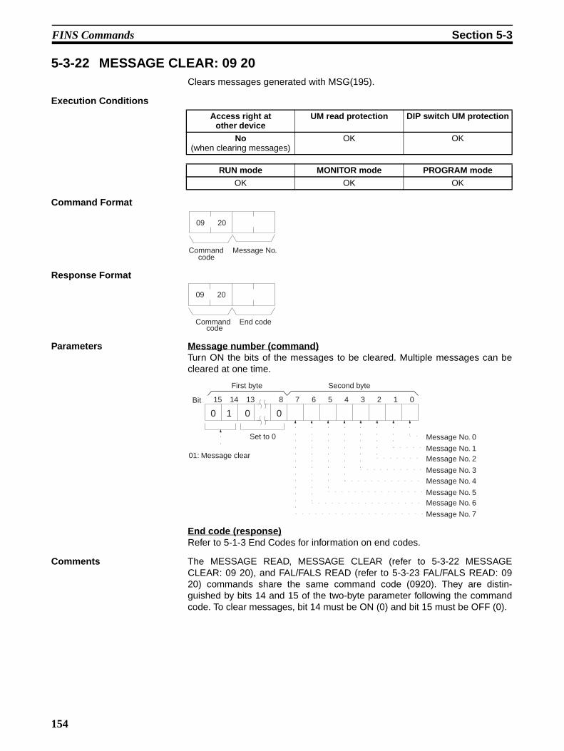
FINS Commands Section 5-3
5-3-22 MESSAGE CLEAR: 09 20Clears messages generated with MSG(195).
Execution Conditions
Command Format
Response Format
Parameters Message number (command)Turn ON the bits of the messages to be cleared. Multiple messages can becleared at one time.
End code (response)Refer to 5-1-3 End Codes for information on end codes.
Comments The MESSAGE READ, MESSAGE CLEAR (refer to 5-3-22 MESSAGECLEAR: 09 20), and FAL/FALS READ (refer to 5-3-23 FAL/FALS READ: 0920) commands share the same command code (0920). They are distin-guished by bits 14 and 15 of the two-byte parameter following the commandcode. To clear messages, bit 14 must be ON (0) and bit 15 must be OFF (0).
Access right at other device
UM read protection DIP switch UM protection
No (when clearing messages)
OK OK
RUN mode MONITOR mode PROGRAM mode
OK OK OK
2009
Command code
Message No.
Command code
2009
End code
15 13 8 7 6 5 4 3 214 1 0
0 1 0 0
Set to 0
Bit
Message No. 0
Message No. 1 Message No. 2
Message No. 3 Message No. 4
Message No. 5 Message No. 6
Message No. 7
Second byteFirst byte
01: Message clear
154
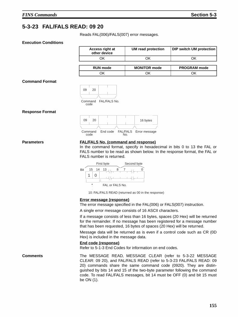
FINS Commands Section 5-3
5-3-23 FAL/FALS READ: 09 20Reads FAL(006)/FALS(007) error messages.
Execution Conditions
Command Format
Response Format
Parameters FAL/FALS No. (command and response)In the command format, specify in hexadecimal in bits 0 to 13 the FAL orFALS number to be read as shown below. In the response format, the FAL orFALS number is returned.
Error message (response)The error message specified in the FAL(006) or FALS(007) instruction.
A single error message consists of 16 ASCII characters.
If a message consists of less than 16 bytes, spaces (20 Hex) will be returnedfor the remainder. If no message has been registered for a message numberthat has been requested, 16 bytes of spaces (20 Hex) will be returned.
Message data will be returned as is even if a control code such as CR (0DHex) is included in the message data.
End code (response)Refer to 5-1-3 End Codes for information on end codes.
Comments The MESSAGE READ, MESSAGE CLEAR (refer to 5-3-22 MESSAGECLEAR: 09 20), and FAL/FALS READ (refer to 5-3-23 FAL/FALS READ: 0920) commands share the same command code (0920). They are distin-guished by bits 14 and 15 of the two-byte parameter following the commandcode. To read FAL/FALS messages, bit 14 must be OFF (0) and bit 15 mustbe ON (1).
Access right at other device
UM read protection DIP switch UM protection
OK OK OK
RUN mode MONITOR mode PROGRAM mode
OK OK OK
Command code
2009
FAL/FALS No.
2009
End codeCommand code
FAL/FALS No.
Error message
16 bytes
15 13 014
1 0
8 7
FAL or FALS No.
Bit
10: FAL/FALS READ (returned as 00 in the response)
Second byteFirst byte
155

FINS Commands Section 5-3
5-3-24 ACCESS RIGHT ACQUIRE: 0C 01Acquires the access right as long as no other device holds it. Execute theACCESS RIGHT ACQUIRE command when you need to execute commandscontinuously without being interrupted by other devices. As soon as the exe-cution of the commands has been completed, execute ACCESS RIGHTRELEASE (command code 0C03) to release the access right. (Refer to 5-3-26 ACCESS RIGHT RELEASE: 0C 03.) If another devices holds the accessright, the device will be identified in the response.
Execution Conditions
Command Format
Response Format
Parameters Program No. (command)Always FFFF (Hex).
End code (response)Refer to 5-1-3 End Codes for information on end codes.
Comments If any other device has the access right, the access right cannot be acquiredwith this command; use ACCESS RIGHT FORCED ACQUIRE (commandcode 0C01). (Refer to 5-3-25 ACCESS RIGHT FORCED ACQUIRE: 0C 02.)
When ACCESS RIGHT ACQUIRE (command code 0C01) is executed whileany other device has the access right, subsequent commands cannot be exe-cuted from the other device. This command should generally not be used dur-ing normal processing.
The following table shows which FINS commands can be executed even
when another device holds the access right.
Access right at other device
UM read protection DIP switch UM protection
No OK OK
RUN mode MONITOR mode PROGRAM mode
OK OK OK
Command code
010C
Program No.
FF FF
End codeCommand code
010C
Unit address of Unit with access rightNode number of device with access right
Network address of device with access right
If any other device holds the access right, the device will be identified.
Command code
Command name Command execution while another device
has access right
0101 MEMORY AREA READ Yes
0102 MEMORY AREA WRITE Yes
0103 MEMORY AREA FILL Yes
0104 MULTIPLE MEMORY AREA READ Yes
156

FINS Commands Section 5-3
Note ACCESS RIGHT ACQUIRE is used to prevent Programming Devices or otherUnits from taking the access right when more than one command is to be exe-cuted in succession. When finished, always execute ACCESS RIGHTRELEASE (0C03).
0105 MEMORY AREA TRANSFER Yes
0201 PARAMETER AREA READ Yes
0202 PARAMETER AREA WRITE No
0203 PARAMETER AREA CLEAR No
0306 PROGRAM AREA READ Yes
0307 PROGRAM AREA WRITE No
0308 PROGRAM AREA 5CLEAR No
0401 RUN No
0402 STOP No
0501 CPU UNIT DATA READ Yes
0502 CONNECTION DATA READ Yes
0601 CPU UNIT STATUS READ Yes
0620 CYCLE TIME READ Yes
0701 CLOCK READ Yes
0702 CLOCK WRITE No
0920 MESSAGE READ/CLEAR No
0C01 ACCESS RIGHT ACQUIRE No
0C02 ACCESS RIGHT FORCED ACQUIRE Yes
0C03 ACCESS RIGHT RELEASE Yes
2101 ERROR CLEAR No
2102 ERROR LOG READ Yes
2103 ERROR LOG CLEAR No
2201 FILE NAME READ Yes
2202 SINGLE FILE READ Yes
2203 SINGLE FILE WRITE No
2204 FILE MEMORY FORMAT No
2205 FILE DELETE No
2207 FILE COPY No
2208 FILE NAME CHANGE No
220A MEMORY AREA–FILE TRANSFER (I/O memory to file transfers only)
No
220B PARAMETER AREA–FILE TRANSFER No
220C PROGRAM AREA–FILE TRANSFER No
2215 CREATE/DELETE DIRECTORY No
2301 FORCED SET/RESET Yes
2302 FORCED SET/RESET CANCEL Yes
Command code
Command name Command execution while another device
has access right
157

FINS Commands Section 5-3
5-3-25 ACCESS RIGHT FORCED ACQUIRE: 0C 02Acquires the access right even if another device already holds it.
Execution Conditions
Command Format
Response Format
Parameters Program number (command)Always FFFF (Hex).
End code (response)Refer to 5-1-3 End Codes for information on end codes.
Comments Even if any other device has the access right, the access right can beacquired with this command and a normal end code will be returned.
When ACCESS RIGHT FORCED ACQUIRE (command code 0C02) is exe-cuted while any other device has the access right, subsequent commandscannot be executed from the other device. This command should generallynot be used during normal processing.
The following table shows which FINS commands can be executed even
when another device holds the access right.
Access right at other device
UM read protection DIP switch UM protection
OK OK OK
RUN mode MONITOR mode PROGRAM mode
OK OK OK
Command code
020C
Program No.
FF FF
Command code
020C
End code
Command code
Command name Command execution while another device
has access right
0101 MEMORY AREA READ Yes
0102 MEMORY AREA WRITE Yes
0103 MEMORY AREA FILL Yes
0104 MULTIPLE MEMORY AREA READ Yes
0105 MEMORY AREA TRANSFER Yes
0201 PARAMETER AREA READ Yes
0202 PARAMETER AREA WRITE No
0203 PARAMETER AREA CLEAR No
0306 PROGRAM AREA READ Yes
0307 PROGRAM AREA WRITE No
0308 PROGRAM AREA CLEAR No
0401 RUN No
0402 STOP No
158

FINS Commands Section 5-3
If this command is executed when another device holds the access right, anyprocessing being executed by that other device will be aborted. If possible,wait until all processing has been completed and then execute ACCESSRIGHT ACQUIRE (command code 0C01). (Refer to 5-3-24 ACCESS RIGHTACQUIRE: 0C 01.)
When the access right is forcibly acquired by this command, the device losingthe access right is not notified.
0501 CPU UNIT DATA READ Yes
0502 CONNECTION DATA READ Yes
0601 CPU UNIT STATUS READ Yes
0620 CYCLE TIME READ Yes
0701 CLOCK READ Yes
0702 CLOCK WRITE No
0920 MESSAGE CLEAR No
0C01 ACCESS RIGHT ACQUIRE No
0C02 ACCESS RIGHT FORCED ACQUIRE Yes
0C03 ACCESS RIGHT RELEASE Yes
2101 ERROR CLEAR No
2102 ERROR LOG READ Yes
2103 ERROR LOG CLEAR No
2201 FILE NAME READ Yes
2202 SINGLE FILE READ Yes
2203 SINGLE FILE WRITE No
2204 FILE MEMORY FORMAT No
2205 FILE DELETE No
2207 FILE COPY No
2208 FILE NAME CHANGE No
220A MEMORY AREA–FILE TRANSFER(I/O memory to file transfers only)
No
220B PARAMETER AREA–FILE TRANSFER No
220C PROGRAM AREA–FILE TRANSFER No
2215 CREATE/DELETE DIRECTORY No
2301 FORCED SET/RESET Yes
2302 FORCED SET/RESET CANCEL Yes
Command code
Command name Command execution while another device
has access right
159

FINS Commands Section 5-3
5-3-26 ACCESS RIGHT RELEASE: 0C 03Releases the access right regardless of what device holds it.
Execution Conditions
Command Format
Response Format
Parameters Program number (command)Always FFFF (Hex).
End code (response)Refer to 5-1-3 End Codes for information on end codes.
Comments The access right can be released by this command even when the accessright is held by another device. In that case a normal end code will bereturned. A normal end code will also be returned if this command is usedwhen the access right is already released.
5-3-27 ERROR CLEAR: 21 01Clears errors or error messages.
Execution Conditions
Command Format
Access right at other device
UM read protection DIP switch UM protection
OK OK OK
RUN mode MONITOR mode PROGRAM mode
OK OK OK
Command code
030C
Program No.
FF FF
030C
Command code
End code
Access right at other device
UM read protection DIP switch UM protection
No OK OK
RUN mode MONITOR mode PROGRAM mode
OK OK OK
Command code
0121
Error reset FAL no.
160

FINS Commands Section 5-3
Response Format
Parameters Error code to reset (command)The code of the error to be reset.
The following codes can be used regardless of the operating mode of the
CPU Unit:
The following codes can be used only when the CPU Unit is in PROGRAM
mode:
End code (response)Refer to 5-1-3 End Codes for information on end codes.
Comments If the specified error is not occurring, a normal end code will be returned.
Command code
0121
End code
Error code Meaning
FFFE Present error cleared. Resets the highest priority error.
008B Interrupt task error.
009A Basic I/O error.
009B PC Setup error.
02F0 Non-fatal Inner Board error.
0300 to 035F Special I/O Unit error.
00A0 to 00A1 SYSMAC BUS error.
0500 to 055F Special I/O Unit setting error.
00E7 I/O verification error. This error occurs if the I/O table differs from the actual I/O points in the System, e.g., an I/O Unit has been added or removed.
00F7 Battery error
0200 to 020F CPU Bus Unit error (the rightmost two digits are the unit number in BCD of the Unit that has the error). This error occurs if there is a parity error at the time of data transfer between the CPU Bus Unit and CPU Unit or if the CPU Bus Unit has a watchdog timer error.
0400 to 040F CPU Bus Unit setting error (the rightmost two digits are the unit number in BCD of the Unit that has the error).FAL(006) executed in the user program.
4101 to 42FF
Error code (Hex)
Meaning
FFFF All errors cleared.
809F Cycle time too long.
80C0 to 80C7 I/O bus error. This error occurs when there is an error in an I/O bus check or a Unit has been removed or added when power is turned on to the PC.
80E0 I/O setting error. This error occurs if the I/O table differs from actual I/O points in the System.
80E1 I/O points overflow
80E9 Duplication error. This error occurs if the same unit number is assigned to more than one Unit or the same word is allocated more than once.
80EA Basic I/O word duplication resulting from rack first word settings.
80F0 Program error.
80F1 Memory error. This error occurs if an error is found in the user program, PC Setup, Registered I/O Tables, routing tables, or CPU Bus Unit Setup memory.
82F0 Fatal Inner Board error.
C101 to C2FF FALS(007) executed.
161

FINS Commands Section 5-3
If the present error is one that can only be cleared when the CPU Unit is inPROGRAM mode, it will not be possible to clear it in MONITOR or RUN mode.
The cause of the error must be removed before executing ERROR CLEAR(command code 2101) or the same error will immediately occur again afterthe command is executed.
5-3-28 ERROR LOG READ: 21 02Reads the PC’s error log.
Execution Conditions
Command Format
Response Format
Parameters Beginning record number (command)Specify the first record to be read. (The first record number is 0000 Hex.)
Number of records (command, response)Specify the number of records to read. The number of read records will bereturned with the response.
Maximum number of stored records (response)Indicates the maximum number of records that can be stored. (Always 20records.)
Number of stored records (response)Indicates the number of records recorded at the time the command is exe-cuted.
Error log data (response)The specified error log records will be returned in sequence starting from thebeginning record number. The total number of bytes required is calculated asfollows:
No. of records x 10 bytes
Access right at other device
UM read protection DIP switch UM protection
OK OK OK
RUN mode MONITOR mode PROGRAM mode
OK OK OK
Command code
0221
Beginning record no.
No. of records
0221
Max. no. of stored records
No. of stored records
No. of records
Error log data
Error log data
End codeCommand code
10 bytes 10 bytes
162

FINS Commands Section 5-3
The configuration of each error record is as follows:
Error code 1, 2Refer to 5-3-27 ERROR CLEAR: 21 01 for information on error codes. Referto the relevant operation manual or installation guide for more details.
Each data record includes the minute, second, day of month, hour (0 to 23),year (the rightmost two digits), and month in BCD specifying the time that theerror occurred.
End code (response)Refer to 5-1-3 End Codes for information on end codes.
Comments The response will contain only the command code and end code if the begin-ning record number is higher than the number of records contained in the PC.
When the PC does not have the specified number of records, all the recordsthat have been stored in the PC will be read and an address range overflowerror will result.
If the data is too large and exceeds the permissible length of the response for-mat, the part in excess will not be read and a normal response will bereturned.
5-3-29 ERROR LOG CLEAR: 21 03Clears all error log pointers to 0.
Execution Conditions
Command Format
Response Format
End code (response)Refer to 5-1-3 End Codes for information on end codes.
Comments This command clears the number of error log records that are stored. It doesnot clear data from the error log area.
MinuteSecond
Day Hour Year MonthError code 2Error code 1
1st byte 10th byte
Access right at other device
UM read protection DIP switch UM protection
No OK OK
RUN mode MONITOR mode PROGRAM mode
OK OK OK
Command format
0321
Command format
0321
End code
163

FINS Commands Section 5-3
5-3-30 FILE NAME READ: 22 01Reads file data such as the names of files saved in file memory.
Execution Conditions
Command Format
Response Format
Parameters Disk number (command)The classification of the file memory with the file name to be read is specifiedas follows:8000 (Hex): Memory card8001 (Hex): EM file memory
Beginning file position (command)The first file to be read. (The first file number is 0000 Hex).
Number of files (command)The number of file names to be read between 0001 and 0014 (Hex). A maxi-mum number of 20 file names can be read at one time. If there are more filenames than that, add one to the number of response files when specifying thenext beginning file position. To read disk data only, specify 0000 (Hex) for boththe beginning file position and the number of file names. A response will bereturned for up to the number of files read.
Directory lengthIndicates the length of the absolute directory path. The maximum number ofcharacters is 65. To specify the root directory as the absolute directory path,specify 0000 (Hex) as the directory length.
Absolute directory pathIndicates the absolute path from the root directory. It begins with ¥ (5C Hex),and the drive name and colon (:) are not required. “¥” is used to delimit thelower directory. It is not required at the end of the final absolute path. No set-ting is required to specify the root directory itself.
Access right at other device
UM read protection DIP switch UM protection
OK OK OK
RUN mode MONITOR mode PROGRAM mode
OK OK OK
Command code
0122
Disk No. No. of files
Beginning file position
Directory length
Absolute directory path
Command code
0122
End code Disk data No. of files
File data File data
22 bytes22 bytes26 bytes
Read file data
164

FINS Commands Section 5-3
Disk data (response)Indicates the file memory data. The configuration is as follows:
Volume LabelThe volume label is the name registered with the file memory. For details onthe configuration, refer to Volume Labels and File Names on page 125.
Date and TimeThe date and time show the date and time that the volume label was created.
Total Capacity and Open CapacityThe total capacity and open capacity show the total capacity of the file mem-ory being used and the number of bytes still available (hexadecimal).
Total Number of FilesThe number of files recorded in the absolute directory path. Volume labels,hidden files, system files, subdirectories, the current directory (indicated by .),and the parent directory (indicated by . .) are all counted as files. (The rootdirectory can contain a volume label, but not a current directory or parentdirectory mark.)
Number of files (response)The number of files that have been read. Bit 15 is ON (1) if the last file isincluded.
File data (response)Each file data consists of 22 bytes. The specified files will be transmitted insequence starting from the first file. The total number of bytes required is cal-culated as follows:
Number of read files x 22 bytes
The configuration for each file data is as follows:
File NameSpecify the name of the file. Refer to Volume Labels and File Names onpage 125 for the structure of file names.
Date and TimeIndicates the date and time at which the file was created. (See the note belowfor details of the configuration.)
File CapacityIndicates the size (the number of bytes, in four digits hexadecimal) of the file.
Volume label
Date/time Total capacity Unused capacity Total no. of files
1st byte
12 bytes
26th byte
Bits 0 to 7 (second byte)
Bits 8 to 15 (first byte)
Bit 15 OFF (0): Without last file Bit 15 ON (1): With last word file Bits 0 to 14: No. of files read
Date/time File capacityFile name
1st byte
12 bytes
22th byte
Attribute
165

FINS Commands Section 5-3
Attribute
Note Date and Time Configuration:The data and time consists of 4 bytes (32 bits) and is configured in the wayshown below.
All data values are in binary.
Year: Add 1980 to the value returned. (The year is the number of years since1980.)
Second: Multiply the value returned by two. (The value returned is expressedin units of two seconds.)
End code (response)Refer to 5-1-3 End Codes for information on end codes.
5-3-31 SINGLE FILE READ: 22 02Reads the contents of a file stored in the file memory.
Execution Conditions
Command Format
Response Format
15 8 7 6 5 4 3 2 1 0
− −Bit
Second byteFirst byte
− −
Reserved area 1: Read-only file
1: Hidden file
1: System file1: Volume label1: Subdirectory
1: Archive file
31
Year(0 to 119)
25 24 21 1620 15 1011 5 4 0toto to to toto
2nd byte 3rd byte 4th byte1st byte
Month (1 to 12)
Minute (0 to 59)
Second (0 to 29)
Day(1 to 31)
Hour (0 to 23)
Bit
7 bits 5 bits6 bits5 bits 5 bits4 bits
Access right at other device
UM read protection DIP switch UM protection
OK OK OK
RUN mode MONITOR mode PROGRAM mode
OK OK OK
File positionDisk No.Command code
22
File name Data length
02 12 bytes
Absolute directory path
Directory length
File capacityEnd codeCommand code
22
Data length
02
File position Data
166

FINS Commands Section 5-3
Parameters Disk number (command)The classification of the file memory with the file name to be read is specifiedas follows:8000 (Hex): Memory card8001 (Hex): EM file memory
File name (command)Specify the name of the file to be read. For details on the configuration, referto Volume Labels and File Names on page 125.
File position (command)Specify the number of bytes (the relative byte address) from the start of thefile from which to start reading. (Files start at 00000000 Hex.)
Data length (command)Specify the number of bytes of data to read.
File capacity (response)The capacity (bytes) of the file that was read is returned.
File position (response)The position of the first data read is returned.
Data length (response)The number of bytes of data read is returned. If the last data in the file isincluded, the leftmost bit in this parameter will be ON.
Data (response)The specified data is returned in sequence starting from the specified byte.
Directory lengthIndicates the length of the absolute directory path. The maximum number ofcharacters is 65. To specify the root directory as the absolute directory path,specify 0000 (Hex) as the directory length.
Absolute directory pathIndicates the absolute path from the root directory. It begins with ¥ (5C Hex),and the drive name and colon (:) are not required. “¥” is used to delimit thelower directory. It is not required at the end of the final absolute path. No set-ting is required to specify the root directory itself.
End code (response)Refer to 5-1-3 End Codes for information on end codes.
Comments By specifying 0000 (Hex) as the file position and data length in the command,is possible to see if the file exists.
5-3-32 SINGLE FILE WRITE: 22 03Writes a new file to the file memory or appends or overwrites an existing filestored in the file memory. Designation can be made to protect existing files ifan attempt is made to create a new file of the same name as an existing file.
Execution ConditionsAccess right at
other deviceUM read protection DIP switch UM protection
No OK OK
RUN mode MONITOR mode PROGRAM mode
OK OK OK
167

FINS Commands Section 5-3
Command Format
Response Format
Parameters Disk number (command)The classification of the file memory with the file name to be read is specifiedas follows:8000 (Hex): Memory card8001 (Hex): EM file memory
Parameter code (command)As follows:
0000 (Hex)Writes a new file. If a file with the same name already exists, the new file willnot be created.
0001 (Hex)Writes a new file. If a file with the same name already exists, it will be overwrit-ten
0002 (Hex)Adds data to an existing file.
0003 (Hex)Overwrites an existing file.
File name (command)Specifies the name of the file to be written. For details on the configuration,refer to Volume Labels and File Names on page 125.
File position (command)Specifies the number of bytes from the start of the file from which to start writ-ing. (Files start at 00000000.) To create a new file or add data to an existingfile, specify 00000000 as the file position.
Data length (command)Specifies the number of bytes to be written.
File data (command)Specifies the data in sequence from the beginning position, in the amountspecified in “data length.”
Directory length (command)Indicates the length of the absolute directory path. The maximum number ofcharacters is 65. To specify the root directory as the absolute directory path,specify 0000 (Hex) as the directory length.
Absolute directory path (command)Indicates the absolute path from the root directory. It begins with ¥ (5C Hex),
Disk noCommand code
22
Data length
03
File positionFile nameParameter code
File data
12 bytes
Directory length
Absolute directory path
End codeCommand code
22 03
168

FINS Commands Section 5-3
and the drive name and colon (:) are not required. “¥” is used to delimit thelower directory. It is not required at the end of the final absolute path. No set-ting is required to specify the root directory itself.
End code (response)Refer to 5-1-3 End Codes for information on end codes.
Comments Writing a new file or modifying an existing file must be done within the capac-ity of the file memory or the SINGLE FILE WRITE command cannot be exe-cuted.
When SINGLE FILE WRITE is executed, the clock data of the CPU Unit willbe recorded as the date of the file.
5-3-33 FILE MEMORY FORMAT: 22 04Formats file memory. Always execute FILE MEMORY FORMAT (commandcode 2204) before using a memory card or EM area as file memory.
Execution Conditions
Command Format
Response Format
Parameters Disk number (command)The classification of the file memory to be formatted is specified as follows:8000 (Hex): Memory card8001 (Hex): EM file memory
End code (response)Refer to 5-1-3 End Codes for information on end codes.
Comments When FILE MEMORY FORMAT (command code 2204) is executed, all dataregistered to the file memory will be cleared. Before executing this command,check to be sure that it is okay to clear the data. Refer to file memory applica-tion procedures in the CPU Unit’s operation manual for details on using filememory.
FILE MEMORY FORMAT is also used to return EM memory that has beenconverted to file memory back to its original form.
Even if only the size of the file memory is changed, the entire file memory willbe formatted.
Note If the current EM bank is specified for file conversion in the PC Setup whenFILE MEMORY FORMAT is executed for the EM Area, an Area Missing error
Access right at other device
UM read protection DIP switch UM protection
No OK OK
RUN mode MONITOR mode PROGRAM mode
OK OK OK
Disk No.
Command code
22 04
End codeCommand code
22 04
169

FINS Commands Section 5-3
(end code 1101) will be returned and a PC Setup setting error will occur in theCPU Unit. These errors, however, will not occur if the current bank is EM0.
5-3-34 FILE DELETE: 22 05Deletes files registered to file memory.
Execution Conditions
Command Format
Response Format
Parameters Disk number (command)The classification of the file memory with the file to be deleted is specified asfollows:8000 (Hex): Memory card8001 (Hex): EM file memory
Number of files (command)Specify the number of files to be deleted.
File name (command)Specify the name of the file to be deleted. For details on the configuration,refer to Volume Labels and File Names on page 125.
Directory lengthIndicates the length of the absolute directory path. The maximum number ofcharacters is 65. To specify the root directory as the absolute directory path,specify 0000 (Hex) as the directory length.
Absolute directory pathIndicates the absolute path from the root directory. It begins with ¥ (5C Hex),and the drive name and colon (:) are not required. “¥” is used to delimit thelower directory. It is not required at the end of the final absolute path. No set-ting is required to specify the root directory itself.
Number of files (response)Indicates the number of files actually deleted.
End code (response)Refer to 5-1-3 End Codes for information on end codes.
Comments The specified files will be deleted in sequence. If non-existing file names havebeen specified, the PC will ignore them and the operation will continue.
Access right at other device
UM read protection DIP switch UM protection
No OK OK
RUN mode MONITOR mode PROGRAM mode
OK OK OK
Disk No.Command code
22 05
No. of files
File name File name
12 bytes 12 bytes
Directory length
Absolute directory path
End codeCommand code
22 05
No. of files
170

FINS Commands Section 5-3
5-3-35 FILE COPY: 22 07Copies a file from one file memory to another file memory connected to thesame CPU Unit.
Execution Conditions
Command Format
Response Format
Parameters Disk number (command)The classification of the copy source and copy destination file memory isspecified as follows:8000 (Hex): Memory card8001 (Hex): EM file memory
File name (command)Specify the file to be copied and a new name for the copy destination file.
Directory lengthIndicates the length of the absolute directory path. The maximum number ofcharacters is 65. To specify the root directory as the absolute directory path,specify 0000 (Hex) as the directory length.
Copy source and copy destination absolute directory pathIndicates the absolute path from the root directory. It begins with ¥ (5C Hex),and the drive name and colon (:) are not required. “¥” is used to delimit thelower directory. It is not required at the end of the final absolute path. No set-ting is required to specify the root directory itself.
End code (response)Refer to 5-1-3 End Codes for information on end codes.
Comments The file will not be copied if there is already a file of the same name at thedestination.
The file will not be copied if an existing file name is given at the copy destina-tion.
The copy destination file is given the same date as the copy source file.
Access right at other device
UM read protection DIP switch UM protection
No OK OK
RUN mode MONITOR mode PROGRAM mode
OK OK OK
Disk No.Command code
22 07
File name Disk No. File name
Source Destination
12 bytes 12 bytes
Directory length
Copy sourceabsolute di-rectory path
Directory length
Copy destination absolute directory
path
End codeCommand code
22 07
171

FINS Commands Section 5-3
5-3-36 FILE NAME CHANGE: 22 08Changes a registered file name.
Execution Conditions
Command Format
Response Format
Parameters Disk number (command)The classification of the file memory where the file name to be changed is reg-istered is specified as follows:8000 (Hex): Memory card8001 (Hex): EM file memory
Old and new file names (command)Specify the original file name and a new name for the file. For details on theconfiguration, refer to Volume Labels and File Names on page 125.
Directory length (command)Indicates the length of the absolute directory path. The maximum number ofcharacters is 65. To specify the root directory as the absolute directory path,specify 0000 (Hex) as the directory length.
Absolute directory path (command)Indicates the absolute path from the root directory. It begins with ¥ (5C Hex),and the drive name and colon (:) are not required. “¥” is used to delimit thelower directory. It is not required at the end of the final absolute path. No set-ting is required to specify the root directory itself.
End code (response)Refer to 5-1-3 End Codes for information on end codes.
Comments The file name will not be changed if an existing file name is specified for thenew file.
Even if the name of a file is changed, the date of the file will remainunchanged.
Directory names can also be changed. Specify the directory name in place ofthe file name.
Access right at other device
UM read protection DIP switch UM protection
No OK OK
RUN mode MONITOR mode PROGRAM mode
OK OK OK
Command code
22 08
Disk No. Old file name New file name
12 bytes 12 bytes
Directory length
Absolute directory path
Command code
22 08
End code
172

FINS Commands Section 5-3
5-3-37 MEMORY AREA–FILE TRANSFER: 22 0ATransfers or compares data between the I/O memory areas and the file mem-ory.
Execution Conditions
Command Format
Response Format
Parameters Parameter code (command)Specify the transfer/compare method as follows:
0000 (Hex)Data transfer from the I/O memory area to the file memory.
0001 (Hex)Data transfer from the file memory to the I/O memory area.
0002 (Hex)Data compared.
I/O memory area code, Beginning address (command)The memory area to be used for data transfer or comparison, and the firstaddress in the memory area to be transferred or compared.
The memory areas that can be written are given in the following table. Refer to5-2-2 I/O Memory Address Designations for the specific addresses that canbe used.
Access right at other device
UM read protection DIP switch UM protection
No OK OK
RUN mode MONITOR mode PROGRAM mode
OK OK OK
Command code
22 0A
File nameParameter code
Beginning address No. of items
Disk No.
Memory area specification
Memory area code
File specification
12 bytes
Directory length
Absolute directory path
22 0A
No. of itemsCommand code
End code
Area Data type Mode memory area code (Hex)
Bytes per element
CIO Area CIO Word B0 2
Work Area WR B1
Holding Bit Area HR B2
Auxiliary Bit Area AR B3
Timer Area TIM PV 89 2
Counter Area CNT
DM Area DM Word 82 2
EM Area EM bank 0 to bank C Word A0 to AC 2
EM current bank Word 98 2
173
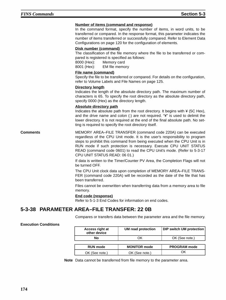
FINS Commands Section 5-3
Number of items (command and response)In the command format, specify the number of items, in word units, to betransferred or compared. In the response format, this parameter indicates thenumber of items transferred or successfully compared. Refer to Element DataConfigurations on page 120 for the configuration of elements.
Disk number (command)The classification of the file memory where the file to be transferred or com-pared is registered is specified as follows:8000 (Hex): Memory card8001 (Hex): EM file memory
File name (command)Specify the file to be transferred or compared. For details on the configuration,refer to Volume Labels and File Names on page 125.
Directory lengthIndicates the length of the absolute directory path. The maximum number ofcharacters is 65. To specify the root directory as the absolute directory path,specify 0000 (Hex) as the directory length.
Absolute directory pathIndicates the absolute path from the root directory. It begins with ¥ (5C Hex),and the drive name and colon (:) are not required. “¥” is used to delimit thelower directory. It is not required at the end of the final absolute path. No set-ting is required to specify the root directory itself.
Comments MEMORY AREA–FILE TRANSFER (command code 220A) can be executedregardless of the CPU Unit mode. It is the user’s responsibility to programsteps to prohibit this command from being executed when the CPU Unit is inRUN mode if such protection is necessary. Execute CPU UNIT STATUSREAD (command code 0601) to read the CPU Unit’s mode. (Refer to 5-3-17CPU UNIT STATUS READ: 06 01.)
If data is written to the Timer/Counter PV Area, the Completion Flags will notbe turned OFF.
The CPU Unit clock data upon completion of MEMORY AREA–FILE TRANS-FER (command code 220A) will be recorded as the date of the file that hasbeen transferred.
Files cannot be overwritten when transferring data from a memory area to filememory.
End code (response)Refer to 5-1-3 End Codes for information on end codes.
5-3-38 PARAMETER AREA–FILE TRANSFER: 22 0BCompares or transfers data between the parameter area and the file memory.
Execution Conditions
Note Data cannot be transferred from file memory to the parameter area.
Access right at other device
UM read protection DIP switch UM protection
No OK OK (See note.)
RUN mode MONITOR mode PROGRAM mode
OK (See note.) OK (See note.) OK
174

FINS Commands Section 5-3
Command Format
Response Format
Parameters Parameter code (command)Specify the transfer/compare method as follows:
0000 (Hex)Data transfer from the parameter area to the file memory.
0001 (Hex)Data transfer from the file memory to the parameter area.
0002 (Hex)Data compared.
Parameter area code (command)Specify the parameter area to be used for data transfer or comparison. Therightmost byte is always 80 (Hex), and the parameter area is specified withthe leftmost byte.
Beginning address (command)Specify the position in the parameter area for beginning the transfer or com-parison. The beginning of each parameter area is always 0000.
Parameter AreasThere are six parameter areas, each of which has consecutive wordaddresses beginning from 0000. The areas that can be written to are shownbelow, along with their parameter area codes.
Number of items (command and response)In the command format, the number of items is always FFFF (Hex) so that theentire parameter area is specified. In the response format, the number ofwords transferred is indicated when data is transferred. When data is com-pared, the response format indicates the position at which a verification erroroccurs or the number of words compared.
Disk number (command)The classification of the file memory where the file to be transferred or com-pared is registered is specified as follows:8000 (Hex): Memory card8001 (Hex): EM file memory
22 0B
File name
Parameter area specification File specification
Parameter area code
Beginning address
Disk No.Command code
Parameter code
No. of items
12 bytes
Directory length
Absolute directory path
22 0B
No. of itemsCommand code
End code
PC Setup Area
I/O Table Registration Area
Routing Table Area
CPU Bus Unit Setup Area
Parameter area code
Address range (Hex)
0000 to 01FF (512 words)
0000 to 04FF (1,280 words)
0000 to 01FF (512 words)
0000 to 143F (5184 words)
8010
8012
8013
8002
Parameter area code
0000 to 1F3F 8000 words)
8000
Address range (Hex)
175

FINS Commands Section 5-3
File name (command)Specify the file to be transferred or compared. For details on the configuration,refer to Volume Labels and File Names on page 125.
Directory length (command)Indicates the length of the absolute directory path. The maximum number ofcharacters is 65. To specify the root directory as the absolute directory path,specify 0000 (Hex) as the directory length.
Absolute directory path (command)Indicates the absolute path from the root directory. It begins with ¥ (5C Hex),and the drive name and colon (:) are not required. “¥” is used to delimit thelower directory. It is not required at the end of the final absolute path. No set-ting is required to specify the root directory itself.
End code (response)Refer to 5-1-3 End Codes for information on end codes.
Comments The clock data upon completion of a parameter area to file memory transferwill be recorded as the date of the file that has been transferred.
A file can be transferred to the I/O table only when the CPU Unit is in PRO-GRAM mode.
This command cannot be executed if any other device holds the access right.
Files cannot be overwritten when transferring data from the parameter area tofile memory.
5-3-39 PROGRAM AREA–FILE TRANSFER: 22 0CCompares or transfers data between the program area and the file memory.
Execution Conditions
Note 1. Data can be transferred from the program area to the file memory.
2. Data cannot be transferred from file memory to the program area in thesemodes.
Command Format
Access right at other device
UM read protection DIP switch UM protection
No OK No (See Note 1.)
RUN mode MONITOR mode PROGRAM mode
OK (See note 2.) OK (See note 2.) OK
22 0C
File nameParameter code
Program area specification File specification
Program No.
Beginning word No. of bytes Disk No.
FF FF 00 00 00 00
Command code
12 bytesFF FF FF FF
Directory length
Absolute directory path
176

FINS Commands Section 5-3
Response Format
Parameters Parameter code (command)Specify the transfer/compare method as follows:
0000 (Hex)Data transfer from the program area to the file memory.
0001 (Hex)Data transfer from the file memory to the program area.
0002 (Hex)Data compared.
Program number and beginning word (command)Always FFFF (Hex).
Beginning word (command)Always 00000000 (Hex).
Number of bytes (command)Specify the number of data bytes to be transferred or compared. AlwaysFFFFFFFF (Hex).
Disk number (command)The classification of the file memory where the file to be transferred or com-pared is registered is specified as follows:8000 (Hex): Memory card8001 (Hex): EM file memory
File name (command)Specify the name of the file to be transferred or compared. For details on theconfiguration, refer to Volume Labels and File Names on page 125.
Data length (response)When data is transferred, the data length parameter indicates the number ofbytes that have been transferred. When data is compared, this parameter indi-cates the amount of data that was compared with no errors, or the number ofbytes compared in a normal completion.
Directory length (response)Indicates the length of the absolute directory path. The maximum number ofcharacters is 65. To specify the root directory as the absolute directory path,specify 0000 (Hex) as the directory length.
Absolute directory path (response)Indicates the absolute path from the root directory. It begins with ¥ (5C Hex),and the drive name and colon (:) are not required. “¥” is used to delimit thelower directory. It is not required at the end of the final absolute path. No set-ting is required to specify the root directory itself.
End code (response)Refer to 5-1-3 End Codes for information on end codes.
Comments The clock data upon completion of a program area to file memory transfer willbe recorded as the date of the file that has been transferred.
This command cannot be executed if any other device holds the access rightor when memory is write-protected via pin 1 of the DIP switch on the frontpanel of the CPU Unit.
Command code
22 0C
End code Data length
177
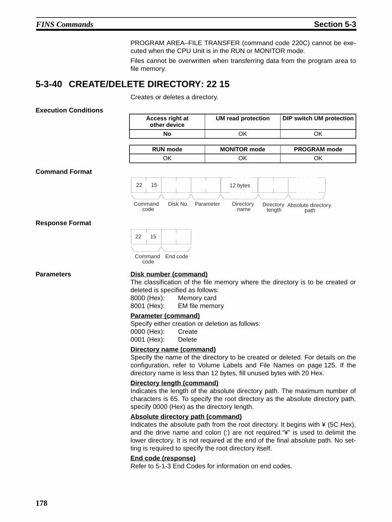
FINS Commands Section 5-3
PROGRAM AREA–FILE TRANSFER (command code 220C) cannot be exe-cuted when the CPU Unit is in the RUN or MONITOR mode.
Files cannot be overwritten when transferring data from the program area tofile memory.
5-3-40 CREATE/DELETE DIRECTORY: 22 15Creates or deletes a directory.
Execution Conditions
Command Format
Response Format
Parameters Disk number (command)The classification of the file memory where the directory is to be created ordeleted is specified as follows:8000 (Hex): Memory card8001 (Hex): EM file memory
Parameter (command)Specify either creation or deletion as follows:0000 (Hex): Create0001 (Hex): Delete
Directory name (command)Specify the name of the directory to be created or deleted. For details on theconfiguration, refer to Volume Labels and File Names on page 125. If thedirectory name is less than 12 bytes, fill unused bytes with 20 Hex.
Directory length (command)Indicates the length of the absolute directory path. The maximum number ofcharacters is 65. To specify the root directory as the absolute directory path,specify 0000 (Hex) as the directory length.
Absolute directory path (command)Indicates the absolute path from the root directory. It begins with ¥ (5C Hex),and the drive name and colon (:) are not required.“¥” is used to delimit thelower directory. It is not required at the end of the final absolute path. No set-ting is required to specify the root directory itself.
End code (response)Refer to 5-1-3 End Codes for information on end codes.
Access right at other device
UM read protection DIP switch UM protection
No OK OK
RUN mode MONITOR mode PROGRAM mode
OK OK OK
22 15
ParameterCommand code
Disk No.
12 bytes
Directory length
Absolute directory path
Directory name
22 15
Command code
End code
178

FINS Commands Section 5-3
Comments The CPU Unit’s clock data will be recorded as the date of any directory that iscreated.
5-3-41 FORCED SET/RESET: 23 01Force-sets (ON) or force-resets (OFF) bits/flags or releases force-set status.Bits/flags that are forced ON or OFF will remain ON or OFF and cannot bewritten to until the forced status is released.
Execution Conditions
Note “Forced status” means that the ON/OFF status of the bit/flag is forciblyretained and writing is prohibited.
Command Format
Response Format
Parameters Number of bits/flags (command)Specify the number of bits/flags to be controlled.
Set/reset designation (command)Specify the action to be taken for each bit/flag.
I/O memory area code (command)Specify the I/O memory area of the bit or flag to be controlled.
Bit/Flag (command)Specify the bit or flag to be controlled. The memory areas in which bits/flags
Access right at other device
UM read protection DIP switch UM protection
OK OK OK
RUN mode MONITOR mode PROGRAM mode
No OK OK
Command code
23 01
No. of bits/flags
Bit/flag Set/reset designation
Forced set/reset data
Bit/flag
Forced set/reset data
Set/reset designation
I/O memory area codeI/O memory area code
Command code
23 01
End code
Value (Hex)
Name Operation
0000 Forced reset Turns OFF (0) the bit/flag and places it in forced status. (See note.)
0001 Forced set Turns ON (1) the bit/flag and places it in forced status.
8000 Forced set/reset OFF release Turns OFF (0) the bit/flag and releases the forced status.
8001 Forced set/reset ON release Turns ON (1) the bit/flag and releases the forced status.
FFFF Forced set/reset release Releases the forced status while retaining the ON/OFF status.
179
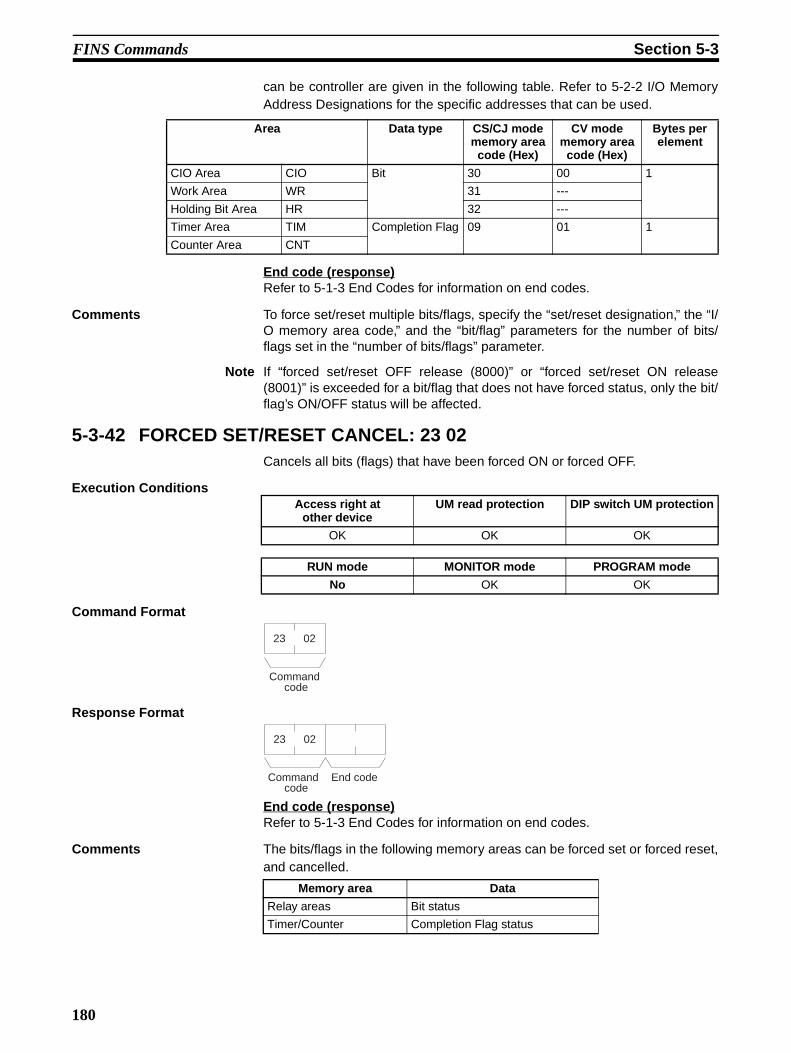
FINS Commands Section 5-3
can be controller are given in the following table. Refer to 5-2-2 I/O MemoryAddress Designations for the specific addresses that can be used.
End code (response)Refer to 5-1-3 End Codes for information on end codes.
Comments To force set/reset multiple bits/flags, specify the “set/reset designation,” the “I/O memory area code,” and the “bit/flag” parameters for the number of bits/flags set in the “number of bits/flags” parameter.
Note If “forced set/reset OFF release (8000)” or “forced set/reset ON release(8001)” is exceeded for a bit/flag that does not have forced status, only the bit/flag’s ON/OFF status will be affected.
5-3-42 FORCED SET/RESET CANCEL: 23 02Cancels all bits (flags) that have been forced ON or forced OFF.
Execution Conditions
Command Format
Response Format
End code (response)Refer to 5-1-3 End Codes for information on end codes.
Comments The bits/flags in the following memory areas can be forced set or forced reset,and cancelled.
Area Data type CS/CJ mode memory area
code (Hex)
CV mode memory area
code (Hex)
Bytes per element
CIO Area CIO Bit 30 00 1
Work Area WR 31 ---
Holding Bit Area HR 32 ---
Timer Area TIM Completion Flag 09 01 1
Counter Area CNT
Access right at other device
UM read protection DIP switch UM protection
OK OK OK
RUN mode MONITOR mode PROGRAM mode
No OK OK
Command code
23 02
Command code
23 02
End code
Memory area Data
Relay areas Bit status
Timer/Counter Completion Flag status
180
Index
���ABORT (XZ), 107
access rightacquiring, 5, 110, 112, 156, 158at another device, 127releasing, 5, 110, 112, 160
accessing I/O memory, 4accessing program area, 4, 61
accessing time data, 5, 110, 112
AR AREA READ (RJ), 72
AR AREA WRITE (WJ), 79
ASCII data, 27
bitscontrolling, 179–180
�CIO Area
reading, 131
CIO AREA READ (RR), 66
CIO AREA WRITE (WR), 74
clockreading, 151setting, 151
CMND(490), 26, 47, 51, 126setting example, 36
C-mode commands, 2command formats, 9details, 59–108execution conditions, 65force conditions, 61from host computer, 14list of, 2, 60overview, 7–21partitioned, 10partitioned responses, 11response formats, 9
command formatsfor C-mode commands, 9
commandsC-mode, 2
from host computer, 14overview, 7–21
communications, 2addressed to CS/CJ-series PCs, 2
FINS, 2, 4–5, 23–58parameters, 119partitioned, 10
commands for CV series PCsACCESS RIGHT RELEASE, 160
Communications Port Enabled Flags, 51
Communications Port Error Flags, 51
countersreading Completion Flag status, 131
CPU Unitstatus, 3, 61
cycle timereading, 150
#DA1, 28
DA2, 28
debugging, 5, 111–112
destination node number, 28
destination unit address, 28
DIP switch UM protection, 127
directoriescreating/deleting, 178
DM Areareading, 127, 131writing, 129–130
DM AREA READ (RD), 71
DM AREA WRITE (WD), 78
�EM AREA READ (RE), 73
EM AREA WRITE (WE), 80
end codes, 63–64, 113–121
environmentprecautions, xiii
error log, 5, 110, 112
ERROR READ (MF), 95
error response formatfor C-mode commands, 10
errorsclearing, 160, 163reading, 155, 162
execution conditionsfor C-mode commands, 65for FINS commands, 127
$FAL/FALS messages, 155
fatal error data, 148
FCS calculations, 13
file memory, 5, 111–112
files
181
Index
changing file names, 172comparing, 173–174, 176copying, 171deleting, 170file name configuration, 125reading, 164, 166transferring, 173–174, 176writing, 167
FINS commands, 2, 4–5, 110–111, 126–179addresses, 30command format, 29, 126command frame, 27command settings, 35detailed descriptions, 109execution conditions, 127explanation, 24list of, 4, 110overview, 23–58response format, 30, 126response frame, 27restrictions, 111–112settings for sending, 29timing, 52to CS/CJ-Series CPU Units, 25types of, 24using, 26with Host Link protocol, 37
flagsfor network communications, 51
force conditionsfor C-mode commands, 61
FORCED RESET (KR), 98
FORCED SET (KS), 97
forced set/reset, 3, 61
FORCED SET/RESET CANCEL (KC), 100
�Host Link communications, 27, 127
command frame, 27response frame, 27
Host Link FCS, 38
Host Link header, 38
Host Link terminator, 38
Host Link Unitsfor CS/CJ-series PCs, 8
HR AREA READ (RH), 68
HR AREA WRITE (WH), 76
%�&I/O memory
accessing, 4, 110–111addresses, 119–121reading, 2, 4, 60–61registering, 4, 61table of address designations, 122–127writing, 3, 60
I/O tablecreating, 4, 61
I/O TABLE GENERATE (MI), 104
INITIALIZE (**), 108
installationprecautions, xiii
LR AREA READ (RL), 67
LR AREA WRITE (WL), 75
��'machine configuration
reading, 4, 110, 112
memory areasaccessing I/O, 4comparing/transferring, 173reading, 127, 131transferring data, 133writing, 129–130
messages, 149clearing, 154displaying, 5, 110, 112reading, 152, 155
model code, 3, 61
model numbersreading model numbers of Units, 146reading PC model number, 144
MULTIPLE FORCED SET/RESET (FK), 99
non- fatal error data, 148
(online edit
precautions, xiii
operating environmentprecautions, xiii
operating modechanging, 4, 110, 112
�Parameter Areas
accessing, 4, 110–111clearing, 138comparing/transferring, 174
182

Index
reading, 135writing, 136
partitioned commands, 10
partitioned responses, 11
PCchanging to RUN mode, 142reading controller data, 144
PC model code reading, 3, 61
PC MODEL READ (MM), 101
precautionsapplication, xivgeneral, xioperating environment, xiiisafety, xii
programclearing, 141comparing/transferring, 176reading, 139writing to program area words, 140
program areaaccessing, 4, 61, 110–111
PROGRAM READ (RP), 102
PROGRAM WRITE (WP), 103
READ I/O MEMORY (QQIR), 106
RECV(098), 51
REGISTER I/O MEMORY (QQMR), 105
remote I/O systems, 146
response codes, 63–65, 113–119
response formatsfor C-mode commands, 9
responsespartitioned, 11
�SA1, 28
SA2, 28
safety precautions, xii
SEND(090), 51
service ID, 29
SID, 29
SNA, 28
source network address, 28
source node number, 28
source unit address, 28
statusreading, 5, 110, 112
STATUS CHANGE (SC), 94
STATUS READ (MS), 93
subdirectories, 178
)TEST (TS), 102
testing, 3, 61
time dataaccessing, 5, 110, 112
TIMER/COUNTER PV READ (RC), 69
TIMER/COUNTER PV WRITE (WC), 77
TIMER/COUNTER STATUS READ (RG), 70
TIMER/COUNTER SV CHANGE 1 (W#), 87
TIMER/COUNTER SV CHANGE 2 (W$), 88
TIMER/COUNTER SV CHANGE 3 (W%), 90
TIMER/COUNTER SV READ 1 (R#), 81
TIMER/COUNTER SV READ 2 (R$), 82
TIMER/COUNTER SV READ 3 (R%), 84
timersreading Completion Flag status, 131
��*UM read protection, 127
undefined command (IC), 108
volume labels, 125
183


185
Revision History
A manual revision code appears as a suffix to the catalog number on the front cover of the manual.
The following table outlines the changes made to the manual during each revision. Page numbers refer to the
previous version.Revision code Date Revised content
01 February 1999 Original production
02 September 1999 Page 18: Catalog number corrected for the CQM1 PC.Pages 31, 117: The S+2 beginning read address for the first command word corrected for CMND(490).
03 April 2000 Page 26: Internal communications setting added for DA1 and SA1.Page 28: Values for node address changed in table.Page 37: Last two sentences removed from SA2 description.
04 May 2001 Changes were made throughout the manual to include information for new products (CJ1G-CPU44/45 and CJ1W-SCU41). In addition, the following changes were made.Page 15: Information on words per frame and the response format for MS commands added.Page 18: Note added after first table.Page 45: Information on formats for commands to and responses from the host computer added.Page 57: Information on end code 23 changed.Page 60: Description of “UM Area, Read-protected” changed.Page 63: Information added under “Limitations.”Page 85: Text under second format diagram changed.Page 88: Some error names in the response format diagram changed.Page 118: Information on volume labels and file names changed.Page 125: Information under “Comments” changed.Page 131: Command format diagram changed.Pages 154, 157, 158, 160, 161, 163, 164, 166, 167: Description of directory length changed.Pages 155, 157, 158, 160, 161, 163, 165, 166, 167: Description of absolute directory path changed.Page 156: Information on attribute, and date and time added. “12 bytes” removed from response format diagram.Pages 158, 160: Reference added under “file name.”Page 160: Second paragraph under “Comments” removed.Page 161: Sentence added to first paragraph. Reference added under “old and new file names.”Page 167: Changes made to information under “directory name.”
05 October 2001 Changes were made throughout the manual to include information for new products (CS1G/H-CPU@@H and CJ1G/H-CPU@@H). In addition, the following changes were made.Page ix: Table updated.Page 16, 21: New models added.Page 49: Response Wait Time description corrected.Page 115: “06: Program missing” corrected.Page 117: “02: Parity of checksum” corrected.Page 118: “SFC” removed from “01: No access right.”Page 120: Two illustrations added and top illustration reworded.Page 125: “Hex” added.Page 128: Notes added.Page 132: Sentence added after table.Page 135: Addition made to bottom of page.Page 137: Sentence added toward end of 5-3-8.Page 139 and 140: Number corrected at end of 5-3-10 and 5-3-11.Page 140: Number of bytes description corrected.Page 141: “All clear” removed twice and “execution” changed to “cyclic” twice.Page 143: Addition made to command format and sentence added to end of 5-3-14.Page 144: End of CPU Unit model and version description corrected.Page 145: “Always 23” added to table.Page 151: Addition made to response format.Page 161: Last two lines removed.Page 162: End of 5-3-28 corrected.Page 178: Note moved.Page 179: Table column removed.
Cat. No. W342-E1-05
Revision code

W342-e1-5 02/02 Printed in U.S.A. ©2001 OMRON ELECTRONICS LLC Specifications subject to change without notice.
Sao Paulo 55.11.5564.6488
Buenos Aires 54.114.787.1129
Florida 954.227.2121
800.55.OMRON or 847.843.7900
OMRON ELECTRONICS LLC
1 Commerce DriveSchaumburg, IL 60173 USA800.55.OMRON (66766)
OMRON CANADA, INC.885 Milner AvenueScarborough, Ontario M1B 5V8416.286.6465
OMRON ON-LINEGlobal - http://www.omron.comUSA -http://www.omron.com/oeiCanada -http://www.omron.com/oci