reference manual - saltire simple copy and paste ... want to investigate the follower motion...
TRANSCRIPT

Reference Manual
PO Box 230755Tigard, OR 97281 0755
Analytix Cams 21Cam/Follower Design Software
TM


3Contents
© 2014 Saltire Software Inc.
Table of Contents...................................................................................... 6Welcome
............................................................................................. 6Features Overview
............................................................................................. 6Cams / Followers Supported
............................................................................................. 7System Requirements
............................................................................................. 7Planning Your Design
...................................................................................... 8The Display
............................................................................................. 9Cam/Follower Configuration Area
...................................................................................... 9Examples
............................................................................................. 10Example 1 - Plate Cam
............................................................................................. 14Example 2 - Barrel Cam
............................................................................................. 16Example 3 - Redesigning the Follower
............................................................................................. 18Integrating Cams Into Analytix
...................................................................................... 19Reference Section
............................................................................................. 19Tool Bar
............................................................................................. 20Cam - Follower Types and Data Fields
........................................................................................................ 21Plate
........................................................................................................ 23Barrel
........................................................................................................ 25Linear
............................................................................................. 26Cam / Follower Description Buttons
........................................................................................................ 27Clockwise / Counter Clockwise
........................................................................................................ 27Follower Orientation Below / Above
........................................................................................................ 27Internal / External Cam
........................................................................................................ 28Offset Left / Right
........................................................................................................ 28Barrel Rotating Left / Right
........................................................................................................ 28Upper / Lower Cam Surface

Analytix Cams 21 Reference Manual4
© 2014 Saltire Software Inc.
........................................................................................................ 28Linear Sliding Left / Right
............................................................................................. 29Data Table
........................................................................................................ 29Cam Angle / Displacement
........................................................................................................ 30s (Displacement)
........................................................................................................ 30v (Velocity)
........................................................................................................ 30a (Acceleration)
........................................................................................................ 30j (Jerk)
........................................................................................................ 30x (Cam Profile Coordinate)
........................................................................................................ 30y (Cam Profile Coordinate)
........................................................................................................ 31r (Cam Profile Polar Coordinate)
........................................................................................................ 31theta (Cam Profile Polar Coordinate)
........................................................................................................ 31r.o.c. (Radius of Curvature)
........................................................................................................ 31Pressure Angle
............................................................................................. 31Function Selection
............................................................................................. 34Analysis Area
............................................................................................. 34File Menu
........................................................................................................ 35New
........................................................................................................ 35Open
........................................................................................................ 35Save
........................................................................................................ 35Save As
........................................................................................................ 35Exit
............................................................................................. 35Edit Menu
........................................................................................................ 36Undo
........................................................................................................ 36Redo
........................................................................................................ 36Copy
........................................................................................................ 36Paste
........................................................................................................ 36Options
............................................................................................. 37Help Menu

5Contents
© 2014 Saltire Software Inc.
............................................................................................. 38Index
6
© 2014 Saltire Software Inc.
Analytix Cams 21 Reference Manual
Welcome
Welcome, and thank you for purchasing Analytix Cams 21. This design andanalysis software has the flexibility to allow you to start your designprocess with follower requirements, or with an existing cam profile.
Features Overview
Using Analytix Cams 21, you can focus on optimizingyour cam and follower design rather than spendingtime on tedious manual calculations.
Analytix Cams 21 also increases the reliability and performance of yourcam and follower designs by providing the tools to analyze critical aspectsof a design before physical prototyping or production.
During the design process, Analytix Cams 21 immediately providesgraphical and numerical analysis of critical data, such as cam profile,displacement, velocity, pressure angle, radius of curvature, accelerationand jerk.
Analytix Cams 21 supports convenient data input from external sourcesthrough simple copy and paste commands or with a text file. You can alsocopy graphic illustrations in the main window and paste them into otherapplications for generating reports and presentations.
Cams / Followers Supported
Analytix Cams 21 supports the following basic cam and follower types:
Plate Linear Barrel
Flat / Reciprocating ü
Flat / Oscillating ü
Roller / Reciprocating ü ü ü
Roller / Oscillating ü ü ü
Plate cams with roller followers may be either external or internal. Withlinear and barrel cams, either the top or bottom cam surface may be

Welcome 7
© 2014 Saltire Software Inc.
modeled.
System Requirements
Windows XP or later.
Processor - 1GHz
RAM - 512 MB
Disk Space - 600MB (32 bit)
1.5 GB (64 bit)
Planning Your Design
Before you begin your project, make sure you do the following:
· Decide whether your design approach is based on an existing cam,or based on follower requirements.
· Determine the general size of the cam and follower parameters,such as base circle radius, offset or follower radius.
This guide is written with the assumption that you have knowledge ofmechanical design and cam / follower design principles in particular.
To learn more, consult the following recommended books, which containinformative chapters on cam/follower design:

8
© 2014 Saltire Software Inc.
Analytix Cams 21 Reference Manual
· Design of Machinery, Robert L. Norton, McGraw Hill, 1992.
· Kinematics and Dynamics of Machinery, Charles E. Wilson, J. PeterSadler, Walter J. Michels, Harper & Row, 1983.
· Theory of Machines & Mechanisms, J.E. Shigley & J.J. Uicker,McGraw Hill, 1980
The Display
Here we outline the program elements used to create your Cam design.. Abrief description of each section of the display is provided below.
· Tool Bar - A strip across the top of the window contains thestandard file handling icons, Undo / Redo, Cut / Paste, and fileconfiguration buttons which relate to the Data Table, Function dialogand Cam/Follower Configuration area.
· Cam/Follower Configuration Area - This allows you to selectfrom a drop-down menu the combination of cam and follower youare designing. An illustration representing the cam and followercombination appears as you select from the menu. Furtherspecifications for each cam and follower type are identified with aselection of icons. Refer to the following information about theCam/Follower Configuration Area:
Cam/Follower Configuration Area Data Fields

The Display 9
© 2014 Saltire Software Inc.
Cam/Follower Configuration Area Buttons
· Function dialog - The Apply Function button on the tool bar opensthis dialog for selecting the cam profile curve.
· Data Table - Provides numerical data on cam profile, displacement,velocity, acceleration and jerk (abbreviated in the Data Table as s,v, a, j). This also provides a way to enter a cam profile when in thecam-to-graph mode.
· Analysis - Examine various graphs while defining the values andparameters for the cam and follower.
Cam/Follower Configuration Area
The Cam/Follower Configuration Area allows you to select from adrop-down menu the combination of cam and follower you are designing.
An illustration representing the cam and follower combination appears asyou select from the menu. Any special considerations for different camand follower types are identified.
Refer to the following information in the Reference section about theCam/Follower Configuration Area:
Cam/Follower Types and Data Fields
Cam/Follower Description Buttons
Examples
Analytix Cams presents you with two approaches to designing cams.
Follower-to-Cam - With this method you can quickly and easily createcam profiles based on existing follower requirements. In this mode, youcan design a cam from scratch. Once you have designed the cam, you maywant to investigate the follower motion resulting from using the cam with adifferent follower configuration. Any changes you make to the followergeometry parameters (such as follower offset, follower radius, and followerarm length) affect only the cam profile. The follower motion stays thesame.
In the follower-to-cam mode, you can use the Function window to piecetogether a desired follower motion, or you can paste values for follower

10
© 2014 Saltire Software Inc.
Analytix Cams 21 Reference Manual
displacement directly into the Data Table and Analytix Cams 21 willautomatically derive the cam profile for you.
Cam-to-Follower - If you have an existing cam and want to design orderive the follower motion, this design method lets you input the cam'scoordinates and manipulate parameters of the follower, such as followeroffset, follower radius, and follower arm length. Follower kinematics arederived by the program.
Example 1 - Plate Cam
The Specs
In this example, we design a plate cam with an external reciprocating rollerfollower. Due to design constraints, such as clearances, the base circleradius is 5, the roller offset is .5 and the follower radius is 1. The camrotates counter-clockwise and the follower offset is to the right. Betweencam angle of 0 and 90 degrees the follower has a full cycloidal rise to adisplacement of 1.5; between 90 and 180, a dwell and from 180 to 270degrees a full cycloidal fall back to 0.
Note: You may use any units of length (meters, inches, feet, etc.) as longas they are used consistently throughout the input process. Angles arealways measured in degrees.
Setting the Design Parameters
You can perform the following steps in any order, but you must define eachbefore you begin the "Entering Data" section.
1. Click Follower-to-Cam on the Tool Bar.
2. In the drop-down menu select the combination of cam and followeryou are using. For this example, select Plate-Reciprocating Roller.

Examples 11
© 2014 Saltire Software Inc.
3. Fill in the input parameters.
4. Click the buttons describing the geometric parameters of the cam. In this case we are using the default values.
.
Entering Data
1. In the Edit / Options the default number of Data Points is set to72. This is evenly divided to display data for every 5° of CamAngle. You can change this value to get more or less precision.
2. In the Data list box click and select Cam Angle values for input from0 to 90.
3. Click the Apply Function button to bring up the Function dialog.
4. The Initial Angle and Final Angle should match your selection above.
5. In the drop-down menu select Cycloidal and click the Full Rise
icon .
6. Enter 0 for Initial s and 1.5 for Final s.
· For Oscillating followers displacement will be in degrees.

12
© 2014 Saltire Software Inc.
Analytix Cams 21 Reference Manual
· For Reciprocating followers displacement units are consistentwith base circle radius and follower radius.
7. Click the Apply button to see the first quarter of your cam.
You can modify the data in the table by highlighting the appropriatecells and typing the new values into the table. Then, click Apply again.
8. The next section is the Dwell. Select the next section, highlight the Cam Angle field from 90 to 180 and click Apply Function toregister the new range in the Function dialog. Select Dwell in thedrop-down window. (The first and final displacements are equal.)Type 1.5 in the Initial s field. Click Apply again.
Examples 13
© 2014 Saltire Software Inc.
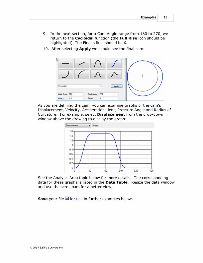
9. In the next section, for a Cam Angle range from 180 to 270, wereturn to the Cycloidal function (the Full Rise icon should behighlighted). The Final s field should be 0.
10. After selecting Apply we should see the final cam.
As you are defining the cam, you can examine graphs of the cam's Displacement, Velocity, Acceleration, Jerk, Pressure Angle and Radius ofCurvature. For example, select Displacement from the drop-downwindow above the drawing to display the graph:
See the Analysis Area topic below for more details. The correspondingdata for these graphs is listed in the Data Table. Resize the data windowand use the scroll bars for a better view.
Save your file for use in further examples below.
14
© 2014 Saltire Software Inc.
Analytix Cams 21 Reference Manual
Example 2 - Barrel Cam
The Specs
In this example, a barrel cam drives a reciprocating follower at a constantvelocity of 0.2 inches / degree between 50 and 200 degrees. Between 0and 50 a half rise cycloidal function smoothly blends in to the constantvelocity portion of the cam. Between 200 and 330 degrees, a 3-4-5polynomial function brings the displacement back to 0. If you have beenworking on another example, select File / New to begin a new model.
Setting the Design Parameters
You can perform the following steps in any order, but you must define eachbefore you begin the "Entering Data" section.
1. Click the Follower-to-Cam button in the Tool Bar.
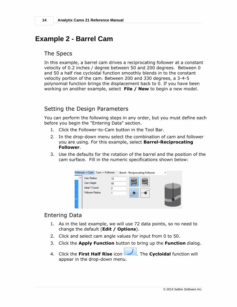
2. In the drop-down menu select the combination of cam and followeryou are using. For this example, select Barrel-ReciprocatingFollower.
3. Use the defaults for the rotation of the barrel and the position of thecam surface. Fill in the numeric specifications shown below:
Entering Data
1. As in the last example, we will use 72 data points, so no need tochange the default (Edit / Options).
2. Click and select cam angle values for input from 0 to 50.
3. Click the Apply Function button to bring up the Function dialog.
4. Click the First Half Rise icon . The Cycloidal function willappear in the drop-down menu.

Examples 15
© 2014 Saltire Software Inc.
5. Check the Initial and Final Angle values.
6. Enter the rest of the data and click Apply.
7. Select the next range from the Data Table, 50 to 200.
8. Enter the Initial s and Initial v. Analytix Cams calculates the Final s.
9. The final segment between 200 and 330 uses the 345-Polynomial
function, Second Half Rise .
10. After entering the Initial s and Initial v, here's how it should look:

16
© 2014 Saltire Software Inc.
Analytix Cams 21 Reference Manual
11. Here is the graph of the velocity:
12. Remember to Save your work for future reference.
Example 3 - Redesigning the Follower
In this example we assume you have manufactured the cam designed inexample 1 above. Now you want to redesign the follower system to meetnew requirements and see the effects on the follower motion.
In the Cam-to-Follower mode, you can change the x and y coordinates.Other than this, any modifications you make to the cam/followerparameters will cause the follower motion to change, but will not affectyour defined cam.
Examples 17
© 2014 Saltire Software Inc.
If you have not saved the previous two examples, find them in the Examples subdirectory of your installation. Alternatively you can use datafrom a text file or Excel.
Setting the Design Parameters
1. If you are using a previously saved file, ex1 for example, open it
.
2. Click the Cam-to-Follower button on the toolbar. The camcoordinate columns will appear first in the Data Table.
3. If you are using other data from a file or cutting and pasting, youmust configure the cam properties. See examples 1 and 2 and CamTypes and Description in the Reference section.
Entering Data q
If you are reading in a text file -
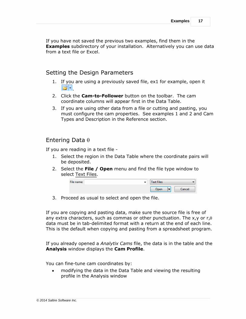
1. Select the region in the Data Table where the coordinate pairs willbe deposited.
2. Select the File / Open menu and find the file type window toselect Text Files.
3. Proceed as usual to select and open the file.
If you are copying and pasting data, make sure the source file is free ofany extra characters, such as commas or other punctuation. The x,y or r,qdata must be in tab-delimited format with a return at the end of each line.This is the default when copying and pasting from a spreadsheet program.
If you already opened a Analytix Cams file, the data is in the table and theAnalysis window displays the Cam Profile.
You can fine-tune cam coordinates by:
· modifying the data in the Data Table and viewing the resultingprofile in the Analysis window

18
© 2014 Saltire Software Inc.
Analytix Cams 21 Reference Manual
· modifying parameters in the Cam/Follower Configuration area.
Modifying follower parameters does not alter the cam profile in this mode.It only modifies the follower kinematics.
Integrating Cams Into Analytix
Analytix 21, the parent program of Analytix Cams 21, is a fully featuredmechanism design package which will import your cam diagram foranalysis in the context of a larger mechanism. You could add linkages,springs, dampers, masses, forces, etc. and analyze resultant forces,torques, tolerance stack-up, trace follower paths by animating themechanism and more. If you don't yet own a copy, you can try a demo.
Here are the simple steps to import your cam into Analytix 21:
1. Save your Analytix Cams file and exit the program.
2. Open Analytix 21 and select Add Cam from the Analysis menu.This opens a new copy of Analytix Cams.
3. In Analytix Cams open your .cam file and select Follower-to-Camor Cam-to-Follower.
· If you select the Follower-to-Cam mode, any changes you makein Analytix to follower parameters (such as follower arm length,follower offset, etc.) will modify the cam profile. The followerkinematics are preserved.
· If you select the Cam-to-Follower mode, changing followerparameters in Analytix will preserve the same cam profile andadjust the follower motion.
4. You can return to Analytix Cams 21 and make more extensivemodifications to the cam by double clicking the cam profile.
5. Exit Analytix Cams 21 and return to Analytix 21.
If you'd like to see more about Analytix 21's capabilities, you can take alook at the manual here.
Reference Section 19
© 2014 Saltire Software Inc.
Reference Section
Here follows a detailed description of the design tools by topic:
· Tool Bar
· Cam / Follower Types and Data Fields
· Cam / Follower Description Buttons
· Data Table
· Analysis Area
· Menus
· File
· Edit
· Help
Tool Bar
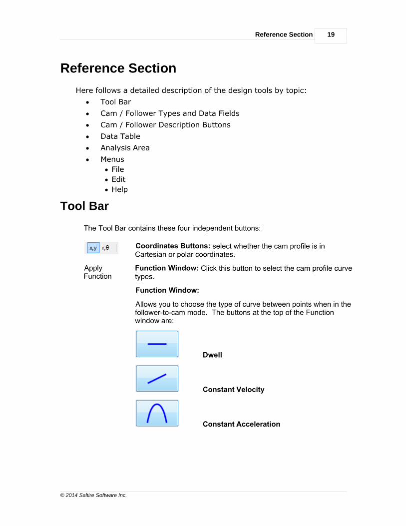
The Tool Bar contains these four independent buttons:
Coordinates Buttons: select whether the cam profile is inCartesian or polar coordinates.
ApplyFunction
Function Window: Click this button to select the cam profile curvetypes.
Function Window:
Allows you to choose the type of curve between points when in thefollower-to-cam mode. The buttons at the top of the Functionwindow are:
Dwell
Constant Velocity
Constant Acceleration

20
© 2014 Saltire Software Inc.
Analytix Cams 21 Reference Manual
Full Rise
First Half
Second Half
Single Dwell
Polynomial Spline
Follower-to-Cam Button: Click to indicate your design approach isfollower-to-cam.
Cam-to-Follower Button: Click to indicate your design approach iscam-to-follower.
Cam - Follower Types and Data Fields
Plate
Reciprocating Flat Face
Reciprocating Roller
Oscillating Flat Face
Oscillating Roller
Barrel
Reciprocating Follower
Oscillating Follower
Linear
Reciprocating Follower
Oscillating Follower

Reference Section 21
© 2014 Saltire Software Inc.
Plate
Reciprocating Flat Face
Base Circle Radius - This is the radius of cam's base circle. (The followerhas 0 displacement when it is lying on the base circle.)
Velocity Units - degrees/length
Buttons:
Clockwise / Counter Clockwise
Reciprocating Roller
Base Circle Radius - This is the radius of cam's base circle. (The followerhas 0 displacement when it is lying on the base circle.)
Offset e - The distance the follower is offset from the line going throughthe axis of the cam.
Follower Radius - The radius of the follower roller.
Velocity Units - degrees/length
Buttons:

22
© 2014 Saltire Software Inc.
Analytix Cams 21 Reference Manual
Clockwise / Counter Clockwise
Left / Right Follower Offset
Internal / External Cam
Oscillating Flat Face
Base Circle Radius - This is the radius of cam's base circle. (The followerhas 0 displacement when it is lying on the base circle.)
Distance AB - The distance from the cam axis to the pivot point of thefollower.
Base Angle ABC - The angle between the follower and the line betweenthe cam axis and the follower pivot when the follower lies on the basecircle.
Offset - The distance of the contact face of the follower from the pivotarm. Positive offset is in a direction toward the cam. Negative offset is ina direction away from the cam.
Velocity Units - degrees/degrees
Ø Note: Changing the base radius of the cam automatically changesthe base angle.
Reference Section 23
© 2014 Saltire Software Inc.
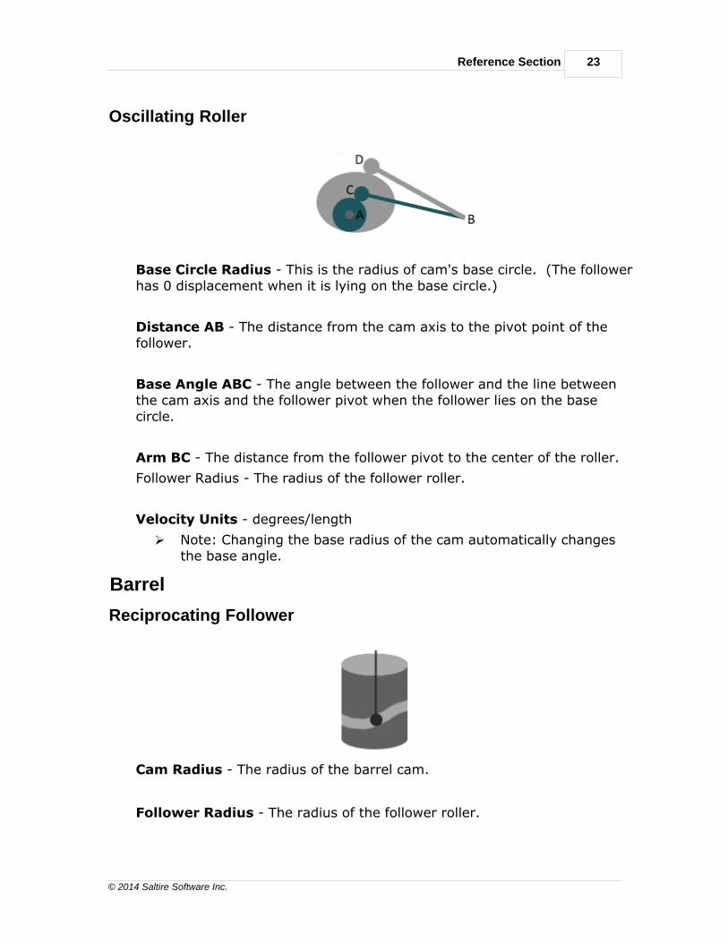
Oscillating Roller
Base Circle Radius - This is the radius of cam's base circle. (The followerhas 0 displacement when it is lying on the base circle.)
Distance AB - The distance from the cam axis to the pivot point of thefollower.
Base Angle ABC - The angle between the follower and the line betweenthe cam axis and the follower pivot when the follower lies on the basecircle.
Arm BC - The distance from the follower pivot to the center of the roller.
Follower Radius - The radius of the follower roller.
Velocity Units - degrees/length
Ø Note: Changing the base radius of the cam automatically changesthe base angle.
Barrel
Reciprocating Follower
Cam Radius - The radius of the barrel cam.
Follower Radius - The radius of the follower roller.

24
© 2014 Saltire Software Inc.
Analytix Cams 21 Reference Manual
Velocity Units - degrees/length
Ø Note: The x coordinate is the angle on the barrel cam measured indegrees.
Oscillating Follower
Cam Radius - The radius of the barrel cam.
Follower Radius - The radius of the follower roller.
Follower Arm - The length of the follower arm from the pivot point to thecenter of the roller.
Pivot X Coord. - The x coordinate of the pivot point. (The leading edge ofthe rectangle representing the cam is assumed to start at x coordinate 0.) A positive value for x positions the pivot to the right of the cam. Anegative value positions the pivot to the left of the cam.
Pivot Y Coord. - The Y coordinate of the pivot point. Y is measured fromthe base of the cam.
Initial Angle - The initial angle of the follower arm (measuredcounter-clockwise from the positive x axis). Angular displacements aremeasured with the initial angle as 0. Positive displacements representcounter-clockwise rotation of the follower.
Velocity Units - degrees/length
Ø Note: The x coordinate is the angle on the barrel cam measured indegrees. The pivot x coordinate can be positive or negative. Theinitial angle is the initial angle of the follower measured from the

Reference Section 25
© 2014 Saltire Software Inc.
positive x axis.
Linear
Reciprocating Follower
Cam Width - The width of the cam.
Follower Radius - The radius of the follower roller.
Velocity Units - degrees/length
Ø Note: Instead of cam angle, you see cam displacement.
Oscillating Follower
Cam Width - The width of the cam.
Follower Radius - The radius of the follower roller.
Follower Arm - The length of the follower arm from the pivot point to thecenter of the roller.
Pivot X Coord. - The x coordinate of the pivot point. (The leading edge ofthe rectangle representing the cam is assumed to start at x coordinate 0.) A positive value for x positions the pivot to the right of the cam. Anegative value positions the pivot to the left of the cam.
26
© 2014 Saltire Software Inc.
Analytix Cams 21 Reference Manual
Pivot Y Coord. - The Y coordinate of the pivot point. Y is measured fromthe base of the cam.
Initial Angle - The initial angle of the follower arm (measuredcounter-clockwise from the positive x axis). Angular displacements aremeasured with the initial angle as 0. Positive displacements representcounter-clockwise rotation of the follower.
Velocity Units - degrees/length
Ø Note: Instead of cam angle, you see cam displacement. The pivot xcoordinate can be positive or negative. The initial angle is the initialangle of the follower measured from the positive x axis.
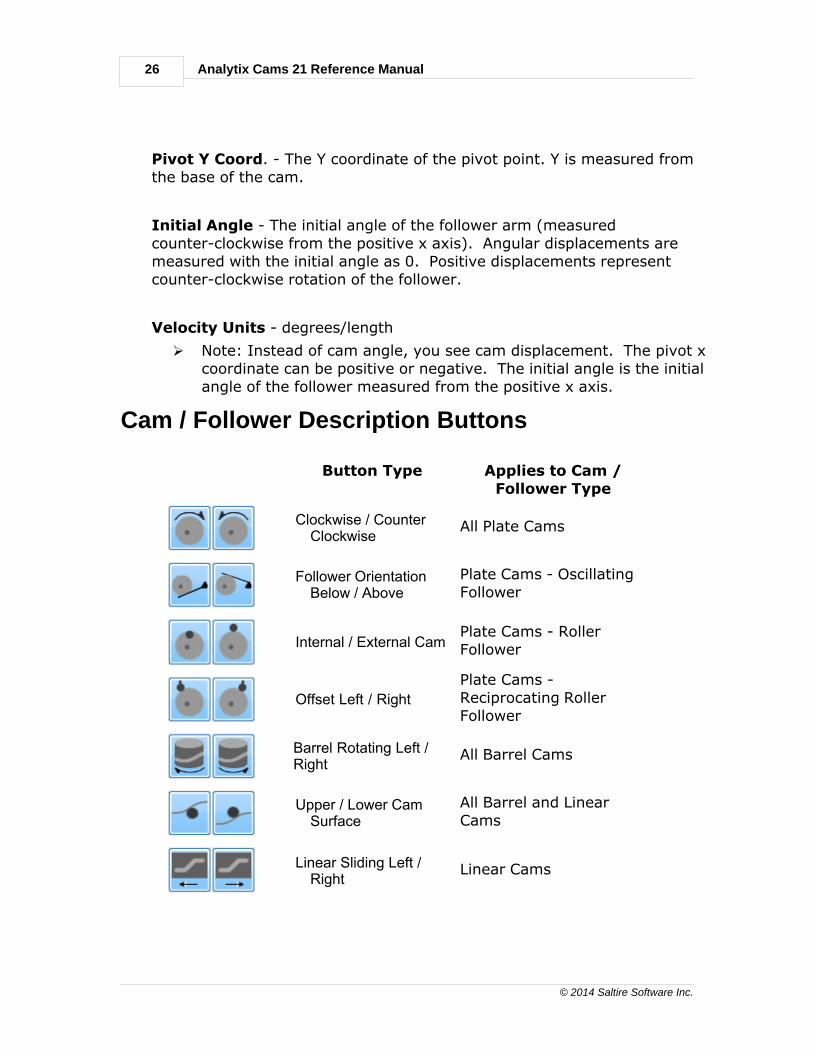
Cam / Follower Description Buttons
Button Type Applies to Cam /Follower Type
Clockwise / CounterClockwise
All Plate Cams
Follower OrientationBelow / Above
Plate Cams - OscillatingFollower
Internal / External CamPlate Cams - RollerFollower
Offset Left / Right
Plate Cams -Reciprocating RollerFollower
Barrel Rotating Left /Right
All Barrel Cams
Upper / Lower CamSurface
All Barrel and LinearCams
Linear Sliding Left /Right
Linear Cams

Reference Section 27
© 2014 Saltire Software Inc.
Clockwise / Counter Clockwise
Specifies the direction of the cam rotation.
Clockwise
Counter Clockwise
Follower Orientation Below / Above
Specifies the orientation of the follower.
Follower is below the cam.
Follower is above the cam.
Internal / External Cam
Specifies that the follower is internal or external to the surface of the cam.
Internal to the cam
External to the cam
28
© 2014 Saltire Software Inc.
Analytix Cams 21 Reference Manual
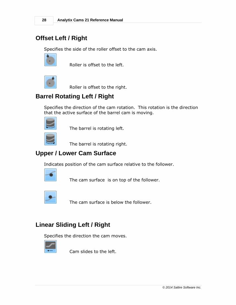
Offset Left / Right
Specifies the side of the roller offset to the cam axis.
Roller is offset to the left.
Roller is offset to the right.
Barrel Rotating Left / Right
Specifies the direction of the cam rotation. This rotation is the directionthat the active surface of the barrel cam is moving.
The barrel is rotating left.
The barrel is rotating right.
Upper / Lower Cam Surface
Indicates position of the cam surface relative to the follower.
The cam surface is on top of the follower.
The cam surface is below the follower.
Linear Sliding Left / Right
Specifies the direction the cam moves.
Cam slides to the left.
Reference Section 29
© 2014 Saltire Software Inc.
Cam slides to the right.
Data Table
The Data Table provides numerical data on displacement, velocity,acceleration and jerk (abbreviated in the Data Table as s, v, a, j). You canenter x / y or r / theta data manually into each cell. You can cut, copy andpaste from a text editor, spreadsheet or other Windows data, or you canhave the cam profile data synthesized by the application, using the Function dialog and the Cam/Follower Configuration options.
The Data Table contains vertical and horizontal scroll bars for viewing data.The columns in the table allow you to expand or reduce the width of acolumn by clicking and dragging the horizontal bar separating eachcolumn.
In the Edit / Options dialog the default number of Data Points is set to72. You can change this value to get more or less precision.
The items below appear as column headings in the Data Table.
Cam Angle
s (Displacement)
v (Velocity)
a (Acceleration)
j (Jerk)
x (Cam Profile Coordinate)
y (Cam Profile Coordinate)
r (Cam Profile Polar Coordinate)
theta (Cam Profile Polar Coordinate)
r.o.c. (Radius of Curvature)
Pressure Angle
Cam Angle / Displacement
Each row of the table represents the relationship between the cam and thefollower at a specific moment in the motion of the cam. The Cam Anglegives the number of degrees the cam has rotated at that moment. In the
30
© 2014 Saltire Software Inc.
Analytix Cams 21 Reference Manual
case of linear cams, this column displays the Cam Displacement.
s (Displacement)
This is the displacement of the follower away from the base displacement. (The base displacement is the location of the follower relative to the basecircle.)
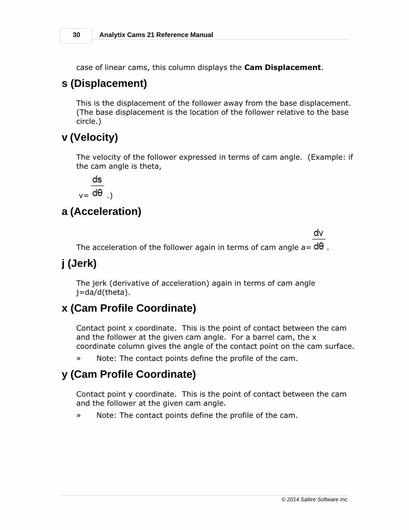
v (Velocity)
The velocity of the follower expressed in terms of cam angle. (Example: ifthe cam angle is theta,
v= .)
a (Acceleration)
The acceleration of the follower again in terms of cam angle a= .
j (Jerk)
The jerk (derivative of acceleration) again in terms of cam anglej=da/d(theta).
x (Cam Profile Coordinate)
Contact point x coordinate. This is the point of contact between the camand the follower at the given cam angle. For a barrel cam, the xcoordinate column gives the angle of the contact point on the cam surface.
» Note: The contact points define the profile of the cam.
y (Cam Profile Coordinate)
Contact point y coordinate. This is the point of contact between the camand the follower at the given cam angle.
» Note: The contact points define the profile of the cam.

Reference Section 31
© 2014 Saltire Software Inc.
r (Cam Profile Polar Coordinate)
Contact point r coordinate. This is the distance (for a given cam angle)from the point of contact between the cam and follower and the center ofthe cam base circle.
» Note: The contact points define the profile of the cam.
theta (Cam Profile Polar Coordinate)
Contact point theta coordinate. This is the orientation (for a given camangle) of the line from point of contact between the cam and follower andthe center of the base circle.
» Note: The contact points define the profile of the cam.
r.o.c. (Radius of Curvature)
r.o.c. gives the radius of curvature of the cam at the contact point.
Pressure Angle
Gives the angle between the direction of motion of the follower and thedirection of the axis in transmission. For flat face followers, the pressureangle is 0.
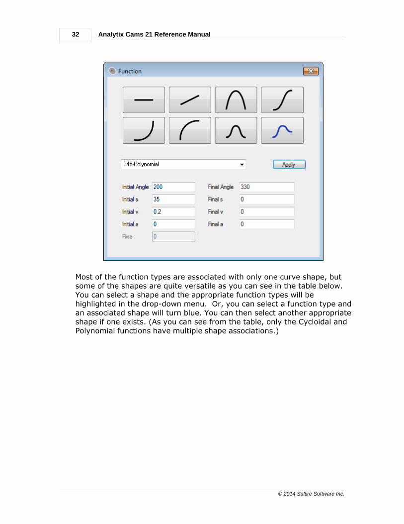
Function Selection
The Function dialog allows you to choose the type of curve between pointswhen in the Follower-to-Cam mode.
32
© 2014 Saltire Software Inc.
Analytix Cams 21 Reference Manual
Most of the function types are associated with only one curve shape, butsome of the shapes are quite versatile as you can see in the table below. You can select a shape and the appropriate function types will behighlighted in the drop-down menu. Or, you can select a function type andan associated shape will turn blue. You can then select another appropriateshape if one exists. (As you can see from the table, only the Cycloidal andPolynomial functions have multiple shape associations.)

Reference Section 33
© 2014 Saltire Software Inc.
Function Type Curve Shape
Dwell
Dwell
Constant
Velocity
Constant Velocity
Constant
Acceleration
Constant Acceleration
Cycloidal
Full Rise 1st Half Rise 2nd Half Rise
ModifiedHarmonic
Modified Harmonic
ModifiedTrapezoid
Full Rise
Modified Sine
Full Rise
345-Polynomial
Full Rise 1st Half Rise 2nd Half Rise Polynomial Spline
4567-Polynomial
Full Rise 1st Half Rise 2nd Half Rise Polynomial Spline
34
© 2014 Saltire Software Inc.
Analytix Cams 21 Reference Manual
Analysis Area
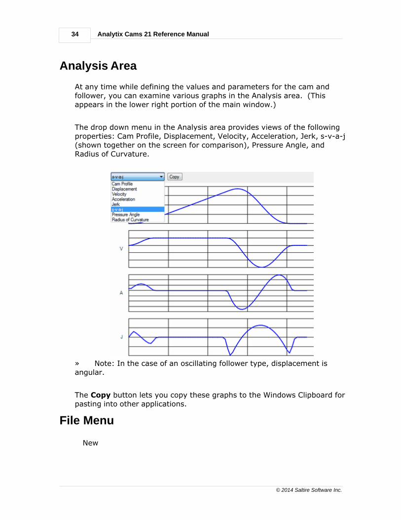
At any time while defining the values and parameters for the cam andfollower, you can examine various graphs in the Analysis area. (Thisappears in the lower right portion of the main window.)
The drop down menu in the Analysis area provides views of the followingproperties: Cam Profile, Displacement, Velocity, Acceleration, Jerk, s-v-a-j(shown together on the screen for comparison), Pressure Angle, andRadius of Curvature.
» Note: In the case of an oscillating follower type, displacement isangular.
The Copy button lets you copy these graphs to the Windows Clipboard forpasting into other applications.
File Menu
New

Reference Section 35
© 2014 Saltire Software Inc.
Open
Save
Save As
Exit
New
Displays a new Analytix Cams 21 window where you can create a newdesign.
Open
Displays an Open dialog box where you can select a design to open or datafrom a text file. Formats you can open include Analytix Cams 21 files(*.cam), or comma- or tab-delimited ASCII. If you open an ASCII file withx,y or r,theta pairs separated by carriage returns, the data will beautomatically inserted into the data table.
Save
Saves the current document using a name you've previously defined.
Save As
Opens the Save As dialog box, which allows you to name the document anddetermine the format in which to save it. Formats include DXF, CAM andtab-delimited ASCII.
Exit
Quits Analytix Cams 21. If you have made modifications to a previouslysaved document or have not yet saved the document, you are given thatoption.
Edit Menu
Undo
Redo
Copy
Paste
Options
36
© 2014 Saltire Software Inc.
Analytix Cams 21 Reference Manual
Undo
Reverses the last action to its previous state.
Redo
Works in conjunction with Undo to reverse the Undo command.
Copy
Leaves the selected text in the document and places a copy on theClipboard for later pasting.
Paste
Places the items on the Clipboard at the insertion point in the document.
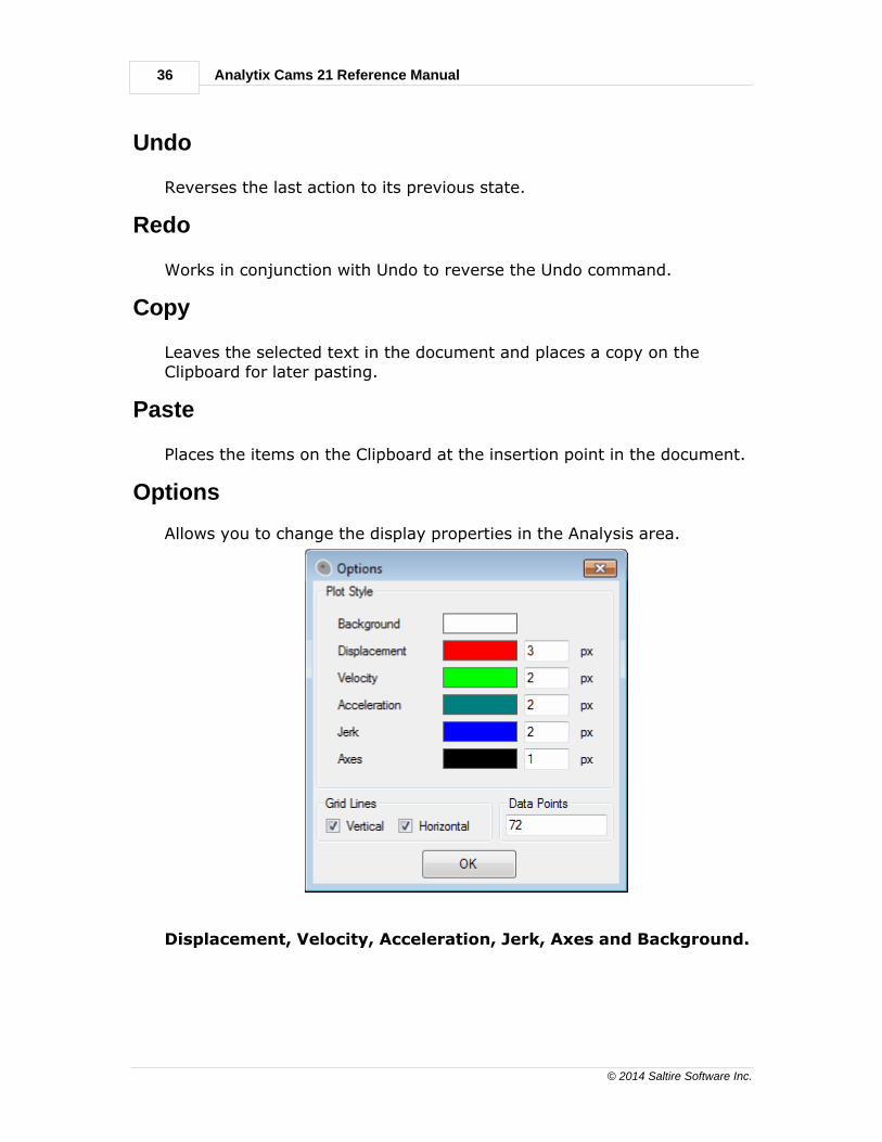
Options
Allows you to change the display properties in the Analysis area.
Displacement, Velocity, Acceleration, Jerk, Axes and Background.
Reference Section 37
© 2014 Saltire Software Inc.
Colors - Click the color box to change the color of the correspondingselection. Choose a Basic color from the Color pallet or click the DefineCustom Colors button to build your own special color.
Line Thickness - Next to the color box is the data entry box for linethickness. A value of 1 is the thinnest.
Grid Lines - Click the appropriate toggle box to display Vertical andHorizontal grid lines.
Data Points - The default is 72. You can change this value by enteringthe desired number.
Click OK to save your changes. To cancel any changes you just made,
click the red X box in the upper right corner of the dialog.
Help Menu
Use the Help menu to electronically access reference information about Analytix Cams 21.

38
© 2014 Saltire Software Inc.
Analytix Cams 21 Reference Manual
Index- A -a (Acceleration) 30
Acceleration 29
Analysis Area 34
Analytix 18
Angle 29, 31
- B -Barrel - Oscillating Follower Data Fields 24
Barrel - Reciprocating Follower Data Fields 23
Barrel cam example 14
Barrel Rotating Left 28
Barrel-Oscillating Follower 9
Barrel-Reciprocating Follower 9
Buttons 19, 27, 28
- C -Cam / Follower
Buttons 26
types and specifications 20
Cam Angle 29
Cam/Follower - Configuration area 9
Cam/Follower Configuration Area 9
Clipboard Button 34
Clockwise 27
Columns in the Data Table 29
Copy 36
Copy (Edit Menu) 36
Copying - to the Windows Clipboard 34
Cutting
Copying and Pasting Data 29
- D -Data Fields 21
Data Table 29
Displacement 29
Displacement - of oscillating follower type 34
- E -Eamples
Redesign 16
Edit Menu 35, 36
Edit Menu - Copy 36
Edit Menu - Options 36
Edit Menu - Paste 36
Edit Menu - Redo 36
Edit Menu - Undo 36
Examining Graphs in the Analysis Area 34
Examples
barrel - reciprocating follower 14
plate - reciprocating roller follower 10
Exit 35
Exit (File Menu) 35
- F -File Menu 34, 35
File Menu - Exit 35
File Menu - New 35
File Menu - Open 35
File Menu - Save 35
File Menu - Save As 35
Follower Orientation Below 27
- H -Help Menu 37
- I -Internal Cam 27
- J -j (Jerk) 30
Jerk 29

Index 39
© 2014 Saltire Software Inc.
- L -Linear - Reciprocating Follower Data Fields 25
Linear Sliding Left 28
Linear-Oscillating Follower 9
Linear-Reciprocating Follower 9
- M -Menus - Edit 36
Menus - File 35
- N -New 35
Numerical Data 29
- O -Offset Left 28
Open 35
Options 36
Options (Edit Menu) 36
- P -Paste 36
Plate - Oscillating Flat Face Data Fields 22
Plate - Oscillating Roller Data Fields 23
Plate cam example 10
Plate-Oscillating Flat Face 9
Plate-Oscillating Roller 9
Plate-Reciprocating Flat Face Data Fields 21
Plate-Reciprocating Roller 9
Plate-Reciprocating Roller Data Fields 21
Pressure Angle 31
- R -r (Cam Profile Polar Coordinate) 31
r.o.c. (Radius of Curvature) 31
Reciprocating Flat Face Data Fields 21
Reciprocating Roller Data Fields 21
Redo 36
Redo (Edit Menu) 36
- S -s (Displacement) 30
Save 35
Save (File Menu) 35
Save As 35
Save As (File Menu) 35
Selecting - a cam/follower combination 9
Synthesizing the Cam Profile 29
- T -theta (Cam Profile Polar Coordinate) 31
Tool Bar 19
Typing Data Into the Data Table 29
- U -Undo 36
Undo (Edit Menu) 36
Upper Cam Surface 28
- V -v (Velocity) 30
Velocity 29
- X -x (Cam Profile Coordinate) 30
- Y -y (Cam Profile Coordinate) 30