reference model for control and automation systems in ... model for control and... · control and...
TRANSCRIPT
Reference Model for
Control and Automation Systems in
Electrical Power
Version 1.2
October 12, 2005
Prepared by: Sandia National Laboratories’ Center for SCADA Security Jason Stamp, Technical Lead Michael Berg, Co-Technical Lead Michael Baca, Project Lead
This work was conducted for the DOE Office of Electricity Delivery and Energy Reliability under Contract M64SCADSNL
Sandia is a multiprogram laboratory operated by Sandia Corporation, a Lockheed Martin Company, for the United States Department of Energy’s
National Nuclear Security Administration under contract DE-AC04-94AL85000.

2
Contents 1 Executive Summary.................................................................................................3
2 Introduction..............................................................................................................4
2.1 SCADA Security......................................................................................................4
2.2 Technical Security Controls.....................................................................................5
3 Automation System Model ......................................................................................5
3.1 Infrastructure Equipment .........................................................................................8
3.1.1 Infrastructure System ...............................................................................8
3.1.2 Actuator....................................................................................................8
3.1.3 Sensor.......................................................................................................8
3.1.4 Field I/O...................................................................................................8
3.2 SCADA Field Equipment ........................................................................................9
3.2.1 I/O Controller ..........................................................................................9
3.2.2 Status Data Field Points ..........................................................................9
3.2.3 Command Data Field Points ...................................................................9
3.2.4 Local Automated Control.........................................................................9
3.3 Control Center........................................................................................................10
3.3.1 System Status Data.................................................................................10
3.3.2 System or Plant Automated Control ......................................................10
3.3.3 System Management Functions..............................................................10
3.3.4 Historical Status Data............................................................................10
3.3.5 Historian ................................................................................................11
3.3.6 Visual and Auditory Representation of Status .......................................11
3.3.7 Operator.................................................................................................11
3.3.8 Exported Data ........................................................................................11
3.3.9 Imported Data ........................................................................................11
3.4 Automation Oversight............................................................................................11
3.4.1 Business Objectives................................................................................11
3.4.2 Oversight Entity or Other SCADA System.............................................12
3.4.3 Regional Control Signal ........................................................................12
4 Utilizing the Model ................................................................................................12
4.1 Mapping Equipment to the Model .........................................................................12
4.2 Data Security..........................................................................................................13
4.3 Electronic Control and Analysis Categories ..........................................................15
4.4 Communication Channels......................................................................................16
4.5 Operation and Configuration .................................................................................16
5 Conclusion .............................................................................................................16
6 Acronyms...............................................................................................................17
7 References..............................................................................................................17
Figure 1: Example of object-role modeling .................................................................. 6 Figure 2: Object-role model for electric power control and automation systems ... 7

3
1 Executive Summary
Modern infrastructure automation systems are threatened by cyber attack. Their higher visibility in recent years and the increasing use of modern information technology (IT) components contribute to increased security risk. A means of analyzing these infrastructure automation systems is needed to help understand and study the many system relationships that affect the overall security of the system. Modeling these systems is a very cost effective means of addressing the problem of security from an overall system view. The reference model for control and automation systems introduced in this paper is based on object-role modeling, and develops fundamental concepts for security based on the analysis of the model. The reference model serves as a foundation for development of a structured approach to best apply technical security controls to SCADA systems in a way that is consistent with the operation and mission of that system. The model is applied to an electric power infrastructure for clarity, but can be adapted for control systems in other sectors. In order to determine an effective strategy to secure a automation systems operation it is necessary to identify system requirements, data categories, functionality, and the system’s internal interdependences. The model described in this paper can be used to identify the required information. The model can also help identify certain single points of failure in the system along with interdependencies that may not otherwise be obvious. The model can be analyzed for generalized security issues in automation systems and it can also be compared to a specific instantiated system. In the general case, using the objects and relationships, many classes and categories of security issues can be inferred. In the specific case, the general security issues identified can be sorted based on the characteristics of the actual system, and the most relevant security concerns may then be considered for remediation. During the course of a risk assessment, it is necessary to determine the impact upon the entire system should a given component fail or become compromised by an attacker. The model enables this determination by illustrating the data dependencies inherent in the process control system. This in turn allows evaluation of the failure or compromise of a component’s functionality in the system that will be directly impacted by its loss, as well as what control loops in the system will be diminished in operation or even completely disrupted. The model can be used to define categories of data sensitivity that correspond to the importance of these control loops. The model provides a structured, cost effective approach to address technical security in process control systems in a way that is consistent with the operation and mission of that system.

4
2 Introduction
Critical infrastructure systems include critical physical processes. These processes are controlled by automation systems which combine humans, computers, communications, and procedures. Automation systems are used to increase the efficiency of process control by trading off high personnel costs for low computer system costs. They also contribute to improved performance by taking advantage of faster computer control instead of human reaction times. These automation systems are often referred to as process control systems (PCS) or supervisory control and data acquisition (SCADA) systems, and the widespread use of such systems makes them critical to the safe, reliable, and efficient operation of many physical processes. Power system operation is becoming ever more complex in today's deregulated environment. Maintaining reliable service depends on increasingly sophisticated control and protection algorithms and also the automation equipment. At the same time, system and device limits are being tested. Interconnected dependent systems give rise to new classes of relationships, both physical and economical. Increased deployment of protection schemes designed to allow increased loading of devices and operation closer to transient and static system limits heightens the possibility of unstable modes resulting from typical stimuli. Complex control at the EMS (energy management systems) level worsens these issues. 2.1 SCADA Security
The term SCADA (supervisory control and data acquisition) is used to represent the communications components and control architecture that provides control capabilities to a power system. Most often included are elements in a power system responsible for system monitoring and control communications. For the purposes of this paper, the term SCADA includes all automation elements for the electrical infrastructure: EMS, protective relaying, AGC (automatic generation control), WAP (wide area protection), communications, etc. Collectively, the elements that make up a SCADA system provide the sensory and command interfaces between the bulk power system and its associated control functions. The link between SCADA and the reliability of the electrical system is well established, as evidenced by the 2003 North American blackout [1]. Because infrastructure operators depend on their automation systems to perform correctly, the infrastructure reliability is degraded by inadequate SCADA reliability and security.

5
2.2 Technical Security Controls
Sandia National Laboratories has authored papers on common vulnerabilities in infrastructure control systems [2] and security management strategies [3]. As clearly stated in these previous articles, technical security controls are only productive in maintaining a secure environment when they are applied in the context of a sustainable security program, which must be based on strong security administration. A SCADA security policy, system-specific security plans, implementation guidance for technology, configuration management, and overall auditing and enforcement are critical to achieve ongoing system security. The remainder of this paper will first introduce a model for infrastructure control systems that provides a discussion framework. Security issues will then be discussed in the context of the control model to describe fundamental concepts for security in automation systems.
3 Automation System Model
Some of the difficulties encountered in discussing security in an automation system are: the lack of security categories for operational data, the use of the same communication channels and network connections for multiple categories of data, and the wide variety of equipment deployed having differing subsets of capabilities between competing vendor’s equipment. The variations for both requirements and architecture that exist between industries and even between companies within the same industry further aggravate these difficulties. System requirements, data categories, and the system’s internal interdependences need to be identified to determine an effective strategy to secure the system’s operation. This paper proposes a model for automation systems that can be used to identify the required information. The model can also help identify certain single points of failure in the system along with interdependencies that may not otherwise be obvious. Object modeling summarizes system control elements logically. This model captures the object-role view of the automation and SCADA systems used in electric power systems, including the classes of objects that are present along with the ways in which they relate to each other (called roles). The roles may exist between one object to another directly, or they may be implied through the relationship of two objects to a third (or others). The improved understanding provided by object modeling is essential to understanding security requirements for automation systems. In object-role modeling, objects or “entity types” are represented as ovals. Roles are represented as a box and explain the relationship between the objects. Referring to Figure 1, the role is read as “Object 1 has relationship 1 to Object 2” and “Object 2 has relationship 2 to Object 1.” Subtype relationships are represented as an arrow. For example, “Object 2” has subtypes of “subtype 1” and “subtype 2.” Similarly, “subtype 1” is one type of “Object 2” and “subtype 2”

6
is another type of “Object 2.” It is worthwhile to point out that objects in the model are types or classes, and that there are frequently more than one instance of that object type in a system. The objects in the model serve as references for features and properties which are common across all instances of that object within the system. For a more thorough introduction to object-role modeling, see [4] and [5].
Object 1 Object 2relationship 2relationship 1 relationship 2relationship 1
subtype 1
subtype 2
Figure 1: Example of object-role modeling
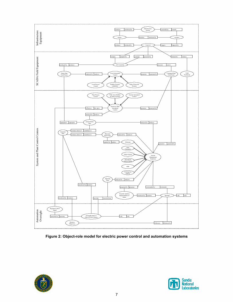
The proposed model for electric power automation systems is depicted in
Figure 2. Four levels of the model are depicted, including Infrastructure Equipment, Automation Field Equipment, the System and Plant Control Centers, and Automation Oversight. These categories, along with the objects and roles within each, are discussed in subsequent sections.
7
Sensor
Infrastructure
Systemmonitored bymonitors monitored bymonitors
monitored bymonitors monitored bymonitors
controlscontrolled by controlscontrolled by
Actuator
Field I/Oproduced byproduces produced byproduces triggered bytriggers triggered bytriggers
Operator
Visual & Auditory
Representation of
Status
sampled bysamples sampled bysamples generated bygenerates generated bygenerates
Status Data
Field Points
Local Automated
Control
Command Data
Field Points
producesproduced by producesproduced by sent toprocesses sent toprocesses
analyzesanalyzed by analyzesanalyzed by generated bygenerates generated bygenerates
System
Management
Functions
aggregatesaggregated aggregatesaggregated
generated bygenerates generated bygenerates
monitorsmonitored by monitorsmonitored by
commandscommanded by commandscommanded bygeneratesgenerated by generatesgenerated by
Operational
System Model
Oversight Entity or
Other SCADA System
monitorsmonitored by monitorsmonitored by
initiatesinitiated by initiatesinitiated by
Field
Technician
callscalls callscalls
analyzesanalyzed by analyzesanalyzed bySystem Status
Data
Historical
Status Data
updatesupdated by updatesupdated by
HMI
Contingency
Planner
Business
Objectivesinfluenced byinfluences influenced byinfluences
I/O Controller
Historian
State
Estimation
analyzesanalyzed by analyzesanalyzed by
System or Plant
Automated
Control
generated bygenerates generated bygenerates
Safety Protection
Systems
analyzesanalyzed by analyzesanalyzed by
monitorsmonitored by monitorsmonitored by
Exported
Data
Imported
Data
contributes tocontains subset of contributes tocontains subset of
contributes tocontains subset of contributes tocontains subset of
received fromprovides received fromprovides
analyzesanalyzed by analyzesanalyzed by
Stability Systems
(reliability)
Wide Area Stability
& Safety Systems
System Automated
Control
Regional Control
Signal
acts uponinfluences acts uponinfluences
generatesgenerated by generatesgenerated by callscalls callscalls
SCADA Field Equipment
System and Plant Control Centers
Automation
Oversight
Infrastructure
Equipment
Alarm System
Local Process
Control
Plant Process
Control
Figure 2: Object-role model for electric power control and automation systems

8
3.1 Infrastructure Equipment
The infrastructure equipment category of the model summarizes each of the non-electronic elements of the control system, along with the peripheral elements of the infrastructure system itself. Equipment in this category is typically located at substations, switchyards, and generating stations.
3.1.1 Infrastructure System
This object class consists of the physical assets that the SCADA system is in place to monitor and control. Examples include: generators, transformers, transmission lines, and motors.
3.1.2 Actuator
An actuator is a device that converts Field I/O into mechanical or electrical actions that will have some effect on the operation of the infrastructure system. Examples include: breakers that energize/de-energize electrical equipment, steam valves to control generator power, tap-changing transformers, excitation controllers, etc.
3.1.3 Sensor
A sensor is a device that monitors the state of an actuator or some property of the infrastructure system and generates an electrical representation of that property. In this model, sensors produce analog Field I/O; examples include current transformers (CTs), potential transformers (PTs), position sensors, temperature probes, pressure and speed sensors, etc.
3.1.4 Field I/O
Field I/O is the object used in this model to group together the analog signals generated by sensors and I/O controllers. The sensor data is connected to I/O controllers, and control data is utilized by actuators and generated by I/O controllers. This representation is useful because an actuator may be triggered by the output of a sensor or it may be triggered by the output of an I/O controller. In this model, Field I/O is an analog value consisting of a voltage or current signal. The Field I/O forms the boundary between the analog control system for the power infrastructure and the electronic automation system. Through the field I/O, the SCADA system interacts with the physical power system in that it provides control directives for the power system (which are largely based upon data feedback from the physical system itself).

9
3.2 SCADA Field Equipment
SCADA field equipment converts between analog Field I/O and digital field points. From the I/O controller on down, the control system elements are to some degree electronic and therefore subject to cyber security control practices. Most of the time, the field equipment functionality is provided by RTUs (Remote Telemetry Units or Remote Terminal Units), PLCs (Programmable Logic Controllers), and IEDs (Intelligent Electronic Devices). These terms refer to the end equipment that interfaces with the process control sensors and actuators. The computational intelligence of these devices may range from the primitive (i.e. simple A/D sampling and communication framing) to advanced (local management of processes through feedback control). These devices are often specialized hardware, with functionality restricted to the operational requirements of the target market. Equipment in this category requires close proximity to the infrastructure equipment to which it is interfaced. The SCADA field equipment is typically either co-located with the infrastructure equipment or it is placed in a nearby building.
3.2.1 I/O Controller
I/O controllers are the interface between the analog Field I/O and the rest of the digital process control system. I/O controllers sample analog Field I/O and generate digital status field points that represent that value. Conversely, I/O controllers process digital command field points and generate the corresponding analog Field I/O. I/O controllers may also perform basic calculations to provide field points for quantities such as active power, reactive power, and power factor that must be derived from other values that were directly measured.
3.2.2 Status Data Field Points
Status data field points are digital representations of sampled Field I/O. They are usually stored in registers within I/O controllers and are read from the I/O controller by other devices or functions in the process control system.
3.2.3 Command Data Field Points
Command data field points are digital values that cause the I/O controller to generate specific Field I/O. They are usually stored in registers within I/O controllers and are written to by other devices or functions within the process control system.
3.2.4 Local Automated Control
Local automated control represents automated actions configured to perform a certain command when certain status conditions are met. Examples include: protective relays in electric power systems, or automatic process shutdowns based on exceeding temperature or pressure thresholds.
10
3.3 Control Center
Control centers denote the operation headquarters for enterprise automation centers. In the control center, electronic systems like automatic generation control (AGC) and disturbance mitigation issue control directives based upon the data feedback. Furthermore, a human element is present in the system control processes, as system operators in the control center can execute power system control by interacting directly with the SCADA system. The human element is included in the automation system model because of its close association with automated system operations. The control center may be separated from the SCADA field equipment by some distance.
3.3.1 System Status Data
System status data is the aggregated set of status data field points. This object in the model may be satisfied with direct communication from the control center to all of the I/O controllers, or it may be satisfied through protocol translation and aggregation gateways (often called front-end processors, or FEPs). Sometimes, IEDs and RTUs may aggregate the field points of devices behind them.
3.3.2 System or Plant Automated Control
These automated control systems are protection, safety, and reliability systems that are in place to respond to changes in the system’s state that require an immediate response without human interaction (and typically at a speed that precludes a human operator). Control systems such as wide area protection (WAP) and automatic generation control (AGC) are examples from electric power. These control signals may extend to other SCADA or automation systems used by partner organizations (called regional control signals, discussed later).
3.3.3 System Management Functions
A system management function is a higher level coordination operation within the automation system. Human-machine interfaces (HMIs), state estimators, and contingency planners are each a type of system management function. A system management function typically contains a mixture of automated actions and actions initiated by a human operator. Some functions such as contingency planners display information to the operator, but do not allow control of the system (control is effected by the operator through the HMI).
3.3.4 Historical Status Data
Historical status data is archived system status data. Due to the large number of field points being monitored and the frequency at which they are updated, historical data almost invariably has some form of trending analysis applied to it. Common data trending methods include storing a single averaged value over some time interval and only storing values when they exceed a specified delta from the last stored value.

11
3.3.5 Historian
The historian is a system management function that converts incoming data into historical data and manages access to that historical data.
3.3.6 Visual and Auditory Representation of Status
Visual and auditory representations of status are the methods by which the information, actions, and operator control interfaces of the system management functions are presented to the SCADA operator, typically through the HMI and alarm subsystems. These representations include one-line diagrams and flow displays on a computer screen or on a wall display. Audible alerts are also used to notify the operators of problems or events that require their attention.
3.3.7 Operator
SCADA operators are the people who review the information presented by the system management functions and moderate or effect control for the SCADA system. SCADA operators are also referred to as “dispatchers” in some industry segments.
3.3.8 Exported Data
Exported data is the data that leaves the SCADA system to the business side of the infrastructure (for billing purposes), to other SCADA systems that activities must be coordinated with, or to an oversight entity which has the job of coordinating multiple infrastructure systems.
3.3.9 Imported Data
Imported data is the system status imported from other SCADA systems or from an oversight entity. The system management functions and the SCADA operator utilize this data to coordinate with other SCADA systems. The imported data could also include regional price signals for economic optimization.
3.4 Automation Oversight
The operation of infrastructures has changed from being considered historically as a public service to more of a business. As such, many data sharing requirements and hierarchical relationships have been added to the SCADA model.
3.4.1 Business Objectives
Many decisions are based on economic models (cost of inputs, processing, distribution, sale price, and contractual obligations). Given that the SCADA system accumulates information about the infrastructure, this data is ideally suited for consideration by the business side of the infrastructure operation, and many systems now export data from the SCADA system to the utility’s administrative network. In the reverse direction, business decisions influence the operation of the SCADA system.
12
3.4.2 Oversight Entity or Other SCADA System
In electric power, these entities could be termed independent system operators (ISOs), regional transmission operators (RTOs), power exchanges (PXs), or other SCADA systems within a control area. In the case of other SCADA systems, typically the operation of the one system relies on data from another. In some industries, there may be contractual or legal requirements for data transfer. Furthermore, it is likely that (where permissible) there will be a speaking relationship between oversight entities and SCADA operators.
3.4.3 Regional Control Signal
A regional control signal is generated by an oversight entity or another SCADA system to affect automated control across multiple SCADA systems. Examples include AGC or WAP signals. Often, these signals represent events that require immediate action to protect or maintain stability among multiple infrastructure entities.
4 Utilizing the Model
The model is intended to be used in one of two ways. First, the model can be analyzed for generalized security issues in automation systems. Using the objects and relationships, many classes and categories of security issues can be inferred, and the majority of the rest of this report investigates this. The model can also be compared to a specific instantiated system. The general security issues identified can be sorted based on the characteristics of the actual system, and the most relevant security concerns may be considered. When the model does not apply to an actual system, significant security analysis could be warranted as the differing architecture might have significant and novel security issues. (Or, perhaps the model does not effectively encapsulate the conditions that led to the development of the differing architecture, which may in fact be adequately secure and reliable. Careful analysis and consideration must be used to decide which is correct.) In the rest of this section, we will consider the general security issues that can be inferred from the reference model. 4.1 Mapping Equipment to the Model
Not every object and role in the model will be present in every process control system. For example, a small, independent manufacturing system is not likely to require the same type of real-time coordination and regional oversight as electric power distribution. As a result, the “Oversight Entity or Other SCADA System” object and any connected roles might not be present when the model is applied to that manufacturing system. With this consideration in mind, the model can now be applied to identify important categories of data, equipment, activities, and properties within the system that must be evaluated when designing security into the system. As previously stated, the model presented in this paper focuses on functionality in automation control systems. This mitigates much of the confusion that arises from the differing feature sets in various vendors’ equipment offerings. Any given

13
piece of automation control equipment will typically perform several functions from the model. In electric power, an RTU might contain integrated I/O controllers to sample the Field I/O directly. Sensors and basic I/O controllers are sometimes integrated to form “smart sensors” that output digital data. One vendor’s RTU might only provide local automated control functionality and rely on external smart sensors or other relays to provide status data field points. A modern protective relay will commonly contain sensors, Field I/O, an I/O controller, status data field points, command data field points, and local automated control. 4.2 Data Security
Referring to the model in Figure 2, several categories of data become apparent:
• Field I/O
• Status Data Field Points
• Command Data Field Points
• System Status Data
• Historical Status Data
• Exported Data
• Imported Data
• Regional Control Signals
Each of these data categories must be protected according to its criticality within the system. Since this paper defines Field I/O as consisting of analog values, physical access is required for direct manipulation. From a remote location, Field I/O can only be influenced indirectly by manipulating communication protocols that are converted to analog Field I/O by an I/O controller. Electronic communication with an I/O controller falls into the category of either status or command data field points. In currently deployed systems, status and command data field points only have physical protection. Local automated control functions that maintain safety and reliability in the system are closely tied to the status and command field points in both physical location and communication connectivity. This all underscores the need for an appropriate level of physical security for devices at the field equipment level that generate, store, and utilize these data field points. System status data is the aggregation of status data field points at the control center. Since this requires the transfer of the status field points across some communication medium, the integrity of this data transfer must be protected. The protection of this data in transit requires either physical protection of the transmission medium or the use of cryptographically secure integrity checks on the data. To prevent unauthorized disclosure of information, confidentiality services may also be necessary. Also at the control center, nearly all systems have a Historian function to store past samples of system status data. Several historian systems provide the

14
capability for host or user based access controls to limit access to historical data. However, such access controls appear to be infrequently utilized in actual deployments. The archived system data often carries significant value, as it relates strongly to production, maintenance, and system performance; therefore, protection of this data should be at the level of its importance. Exported data is a subset of system status data and historical status data (most often the latter, but occasionally the former). Since this data is being exported, it requires holes in the security perimeters that separate the control center from the business IT network, other SCADA systems, and any oversight entities. When exporting this subset of data, safeguards must be in place to insure that the entities to which this data is being exported only have access to the exported data subset and not to the entire system status data and historical status data from which the exported data is derived. External entities must not be able to modify the status or historical data within this SCADA system without authorization. Ideally, they will be provided with a copy of the data and will not have access to the original data sources. All of these details, coupled with the fact that multiple external entities will likely require portions of the exported data, strongly lend themselves to the segregation of the exported data into its own security enclave with security perimeters separating it from the rest of the SCADA system as well as from the external entities to whom the data is being exported. Imported data is interesting in that it resides at a similar level to the system status data generated by this SCADA system, but it is imported from systems outside of the control of this SCADA system. The use of imported data in completely automated operations is relatively rare, but is required in some situations; furthermore, the use of shared and imported data for human-in-the-loop management of system operations is widespread and growing. Importing this data into the SCADA system creates another hole in the security perimeters protecting the SCADA system, and extends some level of control to an external entity if imported data is utilized in automated control functions within this system. The trustworthiness and integrity of this data must be considered when designing the system management functions and when the SCADA operators are making operational decisions. The imported data should be checked for reasonableness, and if possible may be displayed on a separate system from the rest of the SCADA data to avoid mixing the two and creating breaches in the security perimeters. Regional control signals are command channels entering the system from external entities. While these control signals may be required for coordination with other entities and overall system stability, they also create another hole in the security perimeters protecting the SCADA system. The level of trust placed in regional control signals also raises questions about the possible consequences where a falsified control signal might be supplied to the control logic within the SCADA system. The consequences of this are largely hypothetical at this time due to the overall system complexity and other interactions.

15
4.3 Electronic Control and Analysis Categories
Referring to the model in Figure 2, several categories of control become apparent:
• Local automated controls
• System or plant automated controls
• System management functions
• Oversight entities or other SCADA systems
The local and system-wide automated control categories have a level of direct control over the SCADA system with little or no human interaction. Coupled with the fact that these control systems are frequently in place to protect equipment from damage and to quickly address undesirable system conditions, these control systems must be safe-guarded from interruption or compromise. The system management functions and oversight entities have a human involved in the decision making process. However, they also have control over the widest range of equipment and operation of the entire system, and therefore carry considerable risk from unauthorized manipulation of data or control. The model also attempts to capture the control loops inherent in the process control system. During the course of a risk assessment, it is necessary to determine the impact upon the entire system should a given component fail or become compromised by an attacker. Utilizing this model, the failure or compromise of a component can be evaluated for the functionality in the system that will be directly impacted by its loss, as well as what control loops in the system will be diminished in operation or even completely disrupted. It should be noted that multiple levels of control logic in the model must be operating reliably in order for the SCADA operators to have both an accurate representation of the system state as well as the required level of control over the system. The lessons learned from the 2003 northeast blackout about the reliability of SCADA software and its relationship to the stability and security of the entire system further support this observation. Although the blackout depended on tree contacts to get started and the grid’s electrical situation to propagate, the extent of the blackout was facilitated by problems with control functionality at many levels. Besides overgrown trees contacting power lines, the blackout was also triggered by overloads on lines that were mistaken for faults by the local automated controls. Next, the evolving situation was missed by the control center due to malfunctioning software that prevented the system status data from being properly reported to operators. Finally, the oversight entity also had problems with the analysis and display of their data, which left it blind to the problem until it had already grown out of control.

16
4.4 Communication Channels
Once the functionality in the model has been mapped to the equipment in the process control system that provides that functionality, the model can then be used to define categories of data sensitivity that correspond to the importance of the control loops in the system. Data dependencies in the model that are not contained within a single piece of equipment will occur over some communication media such as serial cables or IP based networks. Utilizing the data categories previously identified, the level of security required for the data traversing the communication media and for the media itself should be simple to determine. The communication channel needs to be protected at the level of the highest category of data carried through it. Transporting multiple categories of data on the same medium may also allow an adversary, who can gain access to that channel, access to multiple security domains of the system where much greater control can be influenced. Real-time and bandwidth requirements of each data category needs to be considered. For example, status and command data field points are typically of a real time nature; regional control signals are typically of a near real-time nature, and historical status data is of a loose real-time to non-real-time characteristic. Depending on the industry, imported and exported data might be real-time or non-real-time depending on the level of coordination required with the business side of operations or other SCADA systems. Care must be taken when utilizing the same communication channel for real-time communication and bulk transfers of non-real-time data as large transfers of data could disrupt the transmission of the critical real-time data. 4.5 Operation and Configuration
Finally, given the identification of elements that provide functionality in the acquisition, communication, analysis, and output of data, steps may be taken to protect the operation and configuration of critical platforms. In many cases, this leads to access control and authorization schemes for accessing these devices and functions. Access control can be time-based, host-based, user-based, or role-based, and can depend on multiple authentication factors. Given the criticality of SCADA and infrastructure operations, layers of access restriction will be necessary to adequately ensure the security of the system.
5 Conclusion
The security of automation control systems depends on the effective application of security principles and technology to the system. This paper has proposed a model that illuminates the categories of data, functionality, and interdependencies present in a SCADA system. The model serves as a foundation for development of a structured approach to best apply technical security controls to SCADA systems in a way that is consistent with the operation and mission of that system.

17
6 Acronyms
A/D ............ Analog to digital AGC........... Automatic generation control CT .............. Current transformer EMS........... Energy management system FEP............ Front-end processor HMI ............ Human-machine interface IED............. Intelligent electronic device I/O.............. Input/output IT................ Information technology PCS ........... Process control system PLC............ Programmable logic controller PT .............. Potential transformer PX.............. Power exchange RTO ........... Regional transmission organization RTU ........... Remote terminal unit SCADA ...... Supervisory control and data acquisition
7 References
[1] Final Report on the August 14, 2003 Blackout in the United States and Canada: Causes and Recommendations, U.S.-Canada Power System Outage Task Force, Washington, DC, April 2004.
[2] Common Vulnerabilities in Critical Infrastructure Control Systems, Jason Stamp, John Dillinger, William Young, and Jennifer DePoy, Sandia National Laboratories report SAND2003-1772C, Albuquerque, New Mexico (2003).
[3] Sustainable Security for Infrastructure SCADA, Jason Stamp, Phil Campbell, Jennifer DePoy, John Dillinger, and William Young, Sandia National Laboratories report SAND2003-4670C, Albuquerque, New Mexico (2003).
[4] Object-Role Modeling (ORM/NIAM), Terry Halpin, Microsoft Corporation, USA, http://www.orm.net/pdf/springer.pdf
[5] A Comparison of UML and ORM for Data Modeling, Terry Halpin, Anthony Bloesch, Viso Corporation (1998), http://www.orm.net/pdf/orm-emm98.pdf