reflected fluorescence -...
TRANSCRIPT

INSTRUCTIONS
This instruction manual is for the Olympus Reflected Fluorescence System. To ensure the safety, obtain optimum performance and to familiarize yourself fully with the use of this system, we recommend that you study this manual thoroughly before operating the microscope. Retain this instruction manual in an easily accessible place near the work desk for future reference.
A X 7 8 8 8
BX3-URABX3-RFASU-LH100HGAPOU-LH100HGU-RFL-TU-AN-2BX3-25ND6BX3-25ND25
REFLECTEDFLUORESCENCE
SYSTEM

This device complies with the requirements of both directive 2004/108/EC concerning
electromagnetic compatibility and directive 2006/95/EC concerning low voltage. The CE marking
indicates compliance with the above directives.

CONTENTS
Correct assembly and adjustments are critical for the reflected fluorescence system to exhibit its full performance. If you are going to assemble the reflected fluorescence system yourself, please carefully read section 8, “ASSEMBLY” (pages 24 to 27)
IMPORTANT -- Be sure to read this section for safe use of the equipment. -- 1-3
4-6
19
7,8
20-22
9-19
23
24-27
28
18
1 NOMENCLATURE
5 TROUBLESHOOTING GUIDE
4 SIMULTANEOUS FLUORESCENCE OBSERVATIONS
8 ASSEMBLY -- See this section for the replacement of the light bulb. --
9 LAMP HOUSING INSPECTION SHEET
· BX3-RFAS· BX3-URA
1 General Precautions for Observation ....................................................................................................................... 9
2 Selecting the Fluorescence Mirror Unit ................................................................................................................. 9
3 Turning the Power Supply Unit On ..............................................................................................................................11
4 Centering the Field Iris Diaphragm.............................................................................................................................11
5 Centering the Aperture Iris Diaphragm .................................................................................................................12
6 Centering the Mercury Burner ...........................................................................................................................................13
1 Simultaneous Reflected Fluorescence and Phase Contrast Observations ...........................18
8-1 Assembly Diagram .......................................................................................................................................................................... 24
8-2 Detailed Assembly Procedures ..................................................................................................................................... 25
2
7 Mounting the ND Filters ..............................................................................................................................................................16
8 Attaching the Light Shield Sheet ...................................................................................................................................17
n PROPER SELECTION OF THE POWER SUPPLY CORD .......................................................... 29,30
2 REFLECTED FLUORESCENCE OBSERVATION PROCEDURE
3 USING THE CONTROLS
6 SPECTRAL CHARACTERISTICS OF FILTERS
7 SPECIFICATIONS
Simultaneous Reflected Fluorescence and Transmitted Light NomarskiDifferential Interference Contrast (DIC) Observations ......................................................................................18

1
SAFETY PRECAUTIONS
IMPORTANT
1. This system is composed of precision instruments. Handle it with care and avoid subjecting it to sudden or severe impact.
2. The ultrahigh-pressure mercury burner used should be the USH-103OL that is a DC mercury burner manufactured and supplied by Olympus.
3. Make sure that a mercury burner is attached and that cables are plugged in firmly.4. The inside of the lamp housing is very hot and hazardous during lighting and for about 10 minutes after turning off. Do
not open the lamp housing in this period. (Page 11)5. Do not apply excessive force to the stoppers which are provided for some functions. Otherwise, the stopper or equipment
may be damaged.6. Do not attempt to open, disassemble or modify the power supply unit because it includes high voltage parts inside.7. Always use the power cord provided by Olympus. If no power cord is provided, please select the proper power cord by
referring to the section “PROPER SELECTION OF THE POWER SUPPLY CORD” at the end of this instruction manual. If the proper power cord is not used, product safety and performance cannot be guaranteed.
Before plugging the power cord to the power outlet, make sure that the main switch of the power supply unit is set to “ ” (OFF).
8. To ensure safety, be sure to ground the power supply unit. Otherwise, Olympus can no longer warrant the electrical safety performance of the system.
9. Before opening the lamp housing for replacement of the burner or any other internal part, set the main switch to “ ” (OFF), then unplug the lamp housing connection cable from the power supply unit, and wait for more than 10 minutes until the lamp housing cools down.
This system employs a UIS2 (Universal Infinity System 2) optical design, and should be used only with UIS2 microscopes, eyepieces, objectives and condensers for the BX3 series. (Some of the objectives/eyepieces for the UIS series are also usable. For details, please consult Olympus or the catalogues.)Less than optimum performance may result if inappropriate accessories are used.
Please also read the separately attached instruction manuals listed below to obtain comprehensive understanding of the system operating procedures.
Manual name Main contents
Reflected Fluorescence System (This manual)
Reflected fluorescence observation procedure using the BX3-URA or BX3-RFAS vertical illuminator and the reflected light observation procedure using the BX3-URA.
Information Readout System(U-CBS)
Management of information acquired from the BX3-RFAS cube and U-D7RES objective.
Microscope (BX43, BX53)
Operating procedures of each microscope.
Power Supply Unit(U-RFL-T)
Operating procedures of the power supply unit for the lamp housing for mercury burner.
10. The top panel of the lamp housing becomes very hot during operation. To prevent fire hazard, do not block the ventilation through the top panel.
11. The standard service life of the lamp housing is eight (8) years of use or 20,000 hours of total power ON period, whichever is the shorter period.
For details, see Inspection Sheet on page 28.

2 3
Safety Symbols
The following symbols are found on the microscope. Study the meaning of the symbols and always use the equipment in the safest possible manner.
Symbol Explanation
Indicates the presence of high voltage (1 kV or more). Take caution to guard against electric shock.
Indicates that the surface becomes hot, and should not be touched with bare hands.
Indicates a non-specific general hazard. Follow the description given after this symbol or in instruction manual.
Indicates that the main switch is ON.
Indicates that the main switch is OFF.
Caution indications
Caution indications are placed at parts where special precaution is required when handling and using the System. Always heed the warnings.
Caution indication position
· Lamp housing for mercury burner(U-LH100HG, U-LH100HGAPO)
· Illuminator(BX3-URA, BX3-RFAS)
· ND filter high voltage](BX3-25ND6, BX3-25ND25)
· ND filter slider(provided with BX3-RFAS)
· Power supply unit(U-RFL-T)
[Caution against high temperature]
[Caution against high voltage]
1 Getting Ready
1. This manual pertains only to the reflected fluorescence system. Before using this system together with the BX3 microscope and associated options, make sure that you have carefully read and understood their manuals, and understand how the system should be operated together.
2. The reflected fluorescence system is composed of precision instruments. Handle it with care and avoid subjecting it to sudden or severe impact.
3. Do not use the system where it is subjected to direct sunlight, high temperature and humidity, dust or vibrations.4. To allow heat from the unit to dissipate well, reserve clearances of at least 10 cm around the lamp housing and power
supply unit.5. The power cord can also be used to cut the power supply in case of emergency. To make this possible, the power supply
unit should be installed so that the power cord connector (on the rear of the power supply unit) or the power outlet is easily accessible for unplugging in case of emergency.
6. Before igniting the burner, make sure that a mercury burner is attached and the cords are connected properly.7. Avoid turning the lamp on-off repeatedly as this reduces the burner life considerably. The average service life of a mercury
burner is about 300 hours (USH103OL) with operating cycles of 2-hour ON and 30-minute OFF.

2 3
2 Maintenance and Storage
1. To clean the lenses and other glass components, simply blow dirty away using a commercially available blower and wipe gently using a piece of cleaning paper (or clean gauze).
If a lens is stained with fingerprints or oil smudges, wipe it gauze slightly moistened with commercially available absolute alcohol.
Since the absolute alcohol is highly flammable, it must be handled carefully. Be sure to keep it away from open flames or potential sources of electrical sparks --- for example, electrical
equipment that is being switched on or off. Also remember to always use it only in a well-ventilated room.
2. With any part of the system other than glass components gets dirty, do not use organic solvents but wipe it with a clean cloth. If the part is extremely dirty, use a lint-free, soft cloth slightly moistened with a diluted neutral detergent.
3. Do not disassemble or modify the parts of the system unless when instructed to do so in this manual. Otherwise, malfunction, reduced performance or accident may result.
4. The mercury burner has a service life period of 300 hours (USH-103OL, HBO103W/2). When the hour counter on the power supply unit indicates this value, set the main switch to “ ” (OFF) and wait for more than 10 minutes before replacing the mercury burner (Page 26). Unlike electric bulbs, the mercury burner seals high-pressure gas inside. If it continues to be used after the service life has expired, the glass tube may eventually explode due to accumulated distortion.
5. When not using the microscope, be sure set the main switch to “ ” (OFF). After confirming that the lamp housing has cooled down sufficiently, cover the microscope with the dust cover for storage.
6. When disposing of the system, always follow your local regulations and rules. If you have any question, contact Olympus.
3 Caution
If the system is used in a manner not specified by this manual, the safety of the user may be imperiled. In addition, the system equipment may also be damaged. Always use the system as outlined in this instruction manual.
The following symbols are used to set off text in this instruction manual.
: Indicates a potentially hazardous situation which, if not avoided, may result in minor or moderate injury or damage to the equipment or other property. It may also be used to alert against unsafe practices.
} : Indicates commentary (for ease of operation and maintenance).
CAUTION
CAUTION
4 5
1 NOMENCLATURE
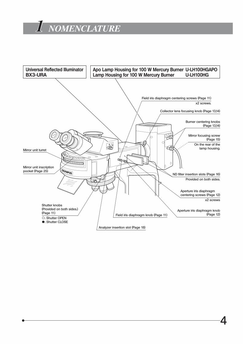
Mirror unit turret
Universal Reflected IlluminatorBX3-URA
Apo Lamp Housing for 100 W Mercury Burner U-LH100HGAPOLamp Housing for 100 W Mercury Burner U-LH100HG
Mirror unit inscriptionpocket (Page 25)
Shutter knobs(Provided on both sides.) (Page 11)
\: Shutter OPEN{: Shutter CLOSE
Field iris diaphragm knob (Page 11)
Analyzer insertion slot (Page 18)
Field iris diaphragm centering screws (Page 11)
x2 screws.
Collector lens focusing knob (Page 13,14)
Burner centering knobs (Page 13,14)
Mirror focusing screw (Page 15)
On the rear of thelamp housing.
ND filter insertion slots (Page 16)
Provided on both sides.
Aperture iris diaphragm centering screws (Page 12)
x2 screws
Aperture iris diaphragm knob (Page 12)

4 5
Coded Fluorescence IlluminatorBX3-RFAS
Lamp Housing for 100 W Mercury BurnerU-LH100HGAPOU-LH100HG
Mirror unit inscriptionpockets (Page 25)
Mirror unit turret
Shutter knobs (Provided on both sides.)(Page 11)
\: Shutter OPEN{: Shutter CLOSE
ND filter slider insertion slot(Page 16)
Insertion from right side.
Aperture iris diaphragm knob (Page 12)
Field iris diaphragm knob (Page 11)
Field iris diaphragm centering screws (Page 11)
Analyzer inlet
Stopper
ND filter slider for BX3-RFAS
Engaged filter name inscription
Stopper
Collector lens focusing knobBurner centering knobs
Mirror focusing screw
(On the rear of the lamp housing.)

6 7
Fluorescence Mirror Units
Indicator sheets
} Up to eight fluorescence mirror units can be mounted on the BX3-URA or BX3-RFAS.
} It is recommended that you use the U-FF dummy mirror unit (which does not contain a filter) when making your original fluorescence mirror unit (page 27).
Blank indicator sheets provided with the illuminator can be used to write the names of original fluorescence mirror units.
Power Supply UnitU-RFL-T/U-RX-T
ND FiltersBX3-25ND6, BX3-25ND25
Centering TargetU-CST
} For details, see the instruction manual provided with the U-RFL-T/U-RX-T.} Use the U-RFL-T when the light source is a mercury burner or use the U-RX-T when the light
source is a xenon burner.
Hour counter
Lamp ON LED
Main switch
I : ON : OFF
Lamp housing connector
Power cord connector

6 7
2 REFLECTED FLUORESCENCE OBSERVATION PROCEDURE
Preparation
Set the main switch to “ I ” (ON) and wait for the lamp brightness to stabilize (5 to 10 minutes after ignition).
Engage the fluorescence mirror unit matching the specimen in the light path.
Engage the objective in the light path and focus on the specimen
Adjust so that the entire field is uniform and brightest.
Adjust the brightness as required.
Engage an ND filter in the light path as required.
Place the specimen on the stage.
} If you need simultaneous observation of reflected fluorescence observation with the phase contrast observation or transmitted light Nomarski Differential Interference Contrast (DIC) observation, please read Chapter 4, “SIMULTANEOUS FLUORESCENCE OBSERVATION”. (Page 18)
(Controls Used) (Page)
· Attach the fluorescence mirror unit and objective matching the observation method. (Pages 9 to 10) · Center the mercury burner. (Pages 13 to 15)
Adjust the field iris diaphragm.
Adjust the aperture irisdiaphragm.
Observation
@Main switch (P.11)
2Slide holder3X-/Y-axis knobs
4Mirror unit turret
5Revolving nosepiece6Coarse/fine adjustment knobs
7ND filter (P.16)
8Collector lens focusing knob (P.13,14)
9Field iris diaphragm knob (P.11)
aAperture iris diaphragm knob (P.12)
bShutter knob (P.11)
BX3-URA BX3-RFAS
} Engage the shutter if you interrupt observation for a short time.

8 9
} Make a photocopy of the observation procedure pages and post it near your microscope.
9
a
7
5
2
8
3
6
b
1
4

8 9
3 USING THE CONTROLS
1 General Precautions for Observation
2 Selecting the Fluorescence Mirror Unit
1. Make sure that the power cord and connecting cables are plugged in securely.2. If you perform only transmitted light phase contrast or transmitted light DIC observations, leave one cube position on the
turret empty. This allows for transmission of white light. The turret must always be set to one of the click position. If it is deviated from a click position, the cover may be deformed
by heat.3. Always use Olympus immersion oil for oil immersion objectives.4. If you use an objective with correction collar, you can correct contrast degradation due to variation in cover glass thickness
by adjusting the correction collar.
Correction procedure
If the cover glass thickness is known, match the correction collar to the cover glass thickness using the collar scale provided. If the thickness is not known, turn the collection collar and adjust the fine adjustment knob to where the image contrast is best.
5. Engage the shutter if you interrupt observation for a short time. (Turning the mercury burner ON and OFF repeatedly will significantly shorten the life span of the burner.)6. Color fading of specimens This system features high excitation light intensity to ensure bright observation of dark fluorescence specimens. In consequence, after long period of observations using high-power objectives, the colors of specimens will fade quicker
than usual, causing the view (contrast) of fluorescent images to deteriorate. In such a case, slightly reduce the excitation light intensity to slow color fading down and improve the fluorescence
images. To reduce the excitation light intensity, use ND filters or aperture iris diaphragm as far as the observation is not affected
or use the shutter to limit the exposure of specimen to more than necessary light. Commercially-marketed color fading protection agent (DABCO, etc.) can also delay fading of specimen colors. The use
of fading protection agent is recommended especially when you perform high-magnification observations frequently.
Remember that the fading protection agents cannot be used with certain kinds of specimens.
Select the fluorescence mirror unit which matches the fluorochrome in use.} Usage according to the excitation light bandwidth: A set combining excitation filters for different bandwidth can be used according to the type of excitation light. The wide-band (W) set is normally used. However, when the fluorescence emitted from substances other than the
fluorescent stain is strong, the Narrow-band (N) set is recommendable.
CAUTION

10 11
Dichroic Mirror and Filter Configurations of Fluorescence Mirror Units
Excitation method
Mirror unit Dichroic mirror Excitation filter Barrier filter Applications
UU-FUW
DM410BP340-390
BA420IF· Autofluorescence observation · DAPI: DNA staining · Hoechest 33258, 33342: Chromosome U-FUN BP360-370
V U-FVN DM455 BP400-410 BA460IF· Catecholamine observation· Serotonin observation· Tetracyline: Bones, teeth
BV U-FBVW DM455 BP400-440 BA460IF
· Quinacrine, quinacrine mustard:Chromosome
· Thioflavine S: Lymphocyte· Acriflavine: Nucleic acid· ECFP
BU-FBW
DM505BP460-495
BA510IF
· FITC: Fluorescent antibody· Acridine orange: DNA, RNA· Auramine: Tubercle bacillus· EGFP, S65T, RSGFPU-FBN BP470-495
G U-FGW DM570 BP530-550 BA575IF· Rhodamine, TRITC:Florescent antibody· Propidium iodide: DNA· RFP
Y U-FYW DM600 BP545-580 BA610IF Texas Red: Fluorescent antibody
Combinations for color separation
U U-FUNA DM410 BP360-370 BA420-460For observing only the U-excitation stain when using U-excitation stain together with FITC.
BU-FBWA
DM505BP460-495
BA510-550For observing only the B-excitation stain when using B-excitation stain with TRITC or Texas Red.U-FBNA BP470-495
GU-FGWA
DM570BP530-550
BA575-625For observing only the G-excitation stain when using G-excitation stain together with Cy5.U-FGNA BP540-550
Exclusive combinations for fluorescent proteins
CFP U-FCFP DM455 BP425-445 BA460-510 For ECFP.
GFP U-FGFP DM490GFP BP460-480 BA495-540 For EGFP.
YFP U-FYFP DM515 BP470-500 BA515-560 For EYFP.
RFP U-FRFP DM565HQ BP535-555HQ BA570-625HQ For RFP.
mCherry U-FMCHE DM595 BP565-585 BA600-690 For mCherry.

10 11
3 Turning the Power Supply Unit On
Set the main switch to “ I ” (ON). The illumination light will stop flickering and will stabilize in 5 to 10 minutes after ignition.} The discharge type mercury burner may not be ignited from the beginning on rare occasions due to its characteristics.
In this case, set the main switch to “ ” (OFF), wait for 5 to 10 seconds, then set it again to “ I ” (ON).
· To extend the mercury burner life, do not turn it on and off at short interval. If you want to interrupt observation for a while in less than 2 hours after ignition, do not switch the power supply unit to off but simply close the shutter of the illuminator during the interruption period.
· The mercury burner cannot be reignited until the mercury vapor has cooled down and liquefied. Before re-igniting a mercury burner, wait for about 10 minutes after the last time it was turned off.
} For the sake of safety, the power supply to the lamp housing is shut down if the lamp housing is opened while the burner is on. If this happens, set the main switch to “ ” (OFF), wait for more than 10 minutes, and then set it again to “ I ” (ON). Whenever you want to open the lamp housing, make sure that it has cooled down enough after use.
After replacing the mercury burner, reset the hour counter by holding its reset button till “0.0” is displayed.
CAUTION
CAUTION
Fig. 1
4 Centering the Field Iris Diaphragm (Fig. 1)
1. Close the light path by sliding the shutter knob @ to position marked {.2. Engage a mirror unit other than the ones for U-excitation (U-FUW, U-FUN,
U-FUNA) in the light path by rotating the turret.3. Open the light path by sliding the shutter knob to position marked \.4 Engage the 10X objective in the light path, place the specimen on the
stage and bring the image into approximate focus.5. Pull out the field iris diaphragm knob 2 to minimize the field iris diameter.6. Fit the Allen screwdriver provided with the microscope frame in the two
field iris centering screws 3 and adjust so that the iris image comes at the center of the field of view.
7. While pushing in the field iris diaphragm knob 2, enlarge the field iris diaphragm until the field iris image inscribes the field of view. If eccentricity is found after this, try centering again.
8. Enlarge the field iris diaphragm.
Effects of Field Iris Diaphragm
The field iris diaphragm restricts the diameter of the beam of light entering the objective and thus excludes extraneous light, improving image contrast. The field iris diaphragm also functions to prevent color fading of fluorescent light in other part than the observed region.
1
3
2

12 13
5 Centering the Aperture Iris Diaphragm (BX3-URA) (Fig. 2)
} This operation is not required with the BX3-RFAS code fluorescence illuminator
1. Close the light path by sliding the shutter knob @ to position marked {.2. Engage a mirror unit other than the ones for U-excitation (U-FUW, U-FUN,
U-FUNA) in the light path by rotating the turret.3. Engage the 10X objective in the light path and lace the U-CST centering
target on the stage.4. Open the light path by sliding the shutter knob to position marked \.5. Move the white surface with cross lines of the U-CST until the cross lines
are overlaid on the center of field.6. Turn the revolving nosepiece to engage the empty place (the objective
cap should be removed) in the light path.7. Pull out the aperture iris diaphragm knob 2 to minimize the aperture iris
diameter.8. Pull out the field iris diaphragm knob 3 to minimize the field iris
diaphragm. Now the aperture iris image should be visible on the U-CST.9. Fit the Allen screwdriver in the two aperture iris centering screws | and
adjust so that the bright dot of the aperture iris image comes on the image center.
Effects of Aperture Iris Diaphragm
The aperture iris diagram helps adjust the brightness of the observed image and improve the contrast.
} The aperture iris diaphragm cannot be used as a substitute to the shutter even when it is stopped down to the minimum aperture.
Fig. 2
13
24

12 13
6 Centering the Mercury Burner
The mercury burner emits light by means of discharge produced when a current is supplied across the poles. If the positions of the poles are moved for example during replacement of the burner, the light would be improperly incident to the specimen and the observation image becomes dark. If this happens, it is necessary to adjust the positions of the poles. This operation is called the centering of mercury burner.
} The mercury burner centering is not required every time before observation, but is recommended after the burner has been replaced or the observation image is dark.
· Operation with BX3-RFAS
} Set the main switch of the power supply unit for lamp housing to “ I ” (ON) and wait until the illumination light stops flickering and its brightness is stabilized.
1. Close the shutter by sliding the shutter knob @ to position marked {.2. Engage a mirror unit other than the ones for U-excitation (U-FUW, U-FUN,
U-FUNA) in the light path. You may use a fluorescence mirror unit for U-excitation if you do not have other mirror units but, in this case, you must always view the images through an anti glare plate.
3. Engage the 10X objective in the light path and place the U-CST centering target on the stage.
4. While looking into the eyepieces, focus on the cross lines for reflected light (white surface).
5. While looking into the eyepieces, adjust the stage to bring the center of the cross lines for reflected light (on the white surface) on the center of the field of view.
6. Turn the revolving nosepiece to engage the empty position (the objective cap should be removed) in the light path.
7. Open the shutter by sliding the shutter knob @ to position marked \. The image by scattered light points will be projected on U-CST.8. While observing the image on U-CST, center the mercury burner by
following steps below.
Centering procedures for Mercury Burner
( i ) Turn the centering knob 3 (the upper knob) to adjust the image on U-CST to be the brightest.
(ii) Turn the centering knob | (the lower knob) to adjust the image on U-CST to be the brightest.} While adjusting ( i ) and (ii), the bright part of the image can be out
of the center of U-CST.(iii) Turn the collector lens focus knob 2 to bring only a part of light to
be remarkably bright. (See Fig. 5).} In actual, the bright part may not necessarily be displayed in the
upper left area as shown in Figure 5.(iv) Turn the centering knob 3 and | to adjust the center of the cross
lines of U-CST to be the brightest.(v) Repeat step (iii) and step (iv) to improve the accuracy for adjust-
ment.
This completes the centering of Mercury Burner.
9. Engage the 10X objective in the light path and while looking into eyepieces, turn the collector lens focus knob 2 to place to the brightest position.
Fig. 3
1
Fig. 4
4
32
Fig. 5

14 15
· Operation with BX3-URA
When the illuminator is the BX3-URA, project the lighting section between the poles (arc image) on the stage and adjust the positions of the poles while observing the arc image position.
} Set the main switch of the power supply unit for lamp housing to “ I ” (ON) and wait until the illumination light stops flickering and its brightness is stabilized.
1. Close the shutter by sliding the shutter knob @ to position marked {.2. Engage a mirror unit other than the ones for U-excitation (U-FUW, U-FUN,
U-FUNA) in the light path. You may use a fluorescence mirror unit for U-excitation if you do not have other mirror units but, in this case, you must always view the images through an anti glare plate.
3. Engage the 10X objective in the light path and place the U-CST centering target on the stage.
4. While looking into the eyepieces, focus on the cross lines for reflected light (white surface).
5. While looking into the eyepieces, adjust the stage to bring the center of the cross lines for reflected light (on the white surface) on the center of the field of view.
6. Turn the revolving nosepiece to engage the empty position (the objective cap should be removed) in the light path.
7. Open the shutter by setting the shutter knob @ to position marked \.8. While looking into the eyepieces, turn the collector lens focusing knob
| to project the arc image and mirror arc image on the U-CST (A in Fig. 7).
} The mirror arc image refers to the arc image projected from the reflection of the lighting section between the poles on the mirror built into the lamp housing.
} If the poles are displaced excessively, the arc image is not projected. In this case, try turning the burner centering knobs 2 3.
9. Bring the arc image on the center of the right (or left) half of the field by turning Turn the burner centering knobs 2 3 (B in Fig. 7).
} Turning the centering knob 2 moves the arc image in the vertical direction and turning the centering knob 3 moves the arc image in the horizontal direction.
Fig. 6
10. Insert the Allen screwdriver into the mirror focusing screw 5 (Fig. 8) on the rear panel of the lamp housing and turn the screw to focus on the mirror arc image (C in Fig. 7).
11. Overlay the arc image with the mirror arc image by turning the burner centering knobs 2 3 (D in Fig. 7).
} During observation, adjust the collector lens focusing knob | so that the observed field is uniform.
Fig. 7
} This figure shows the images of the field of view seen through the eyepieces during the mercury burner centering. The actual views may differ from these images depending on the condition of the lamp housing.
A
B
C
D
1 4
3
2

14 15
Precise Centering of the Mirror (Fig. 8)
} The mirror position has been adjusted and fixed at the factory. When you want to make your adjustments very strict and precise, perform the following procedure after completing the mercury burner centering adjustment described on the previous pages.
Note that, once this adjustment has been executed, the mirror can never be returned to the same status as the factory shipment status.
1. Using a pair of tweezers, etc., peel off the two blind seals 6 from the rear of the lamp housing.
2. Loosen the screws below the seals using the Allen screwdriver. The mirror is unclamped when these two screws are loosened.
3. Then peel off another couple of blind seals †. This exposes the mirror arc image centering holes.
4. Adjust the centering of the mirror arc image using the Allen screwdriver in these holes.
Fig. 8
7
5
6

16 17
7 Mounting the ND Filters
} Specimen color fading can be delayed by reducing the excitation light intensity with ND filters. Use the ND filters as far as they do not hinder observations.
} The figure in the model number of each ND filter represents its transmit-tance.
(Examples) · ND1.5: Transmittance 1.5% · ND6: Transmittance 6% · ND25: Transmittance 25%
Note that the metallic filter frame will be very hot if you leave the filter inserted for a long time while the mercury burner is on.
Do not leave the filter insertion positions in other positions than the click positions for a long period of time.
To switch the ND filter position, hold the ND filter slider by the top and bottom edges and slide it.
Operation with BX3-URA (Fig. 9)
1. Insert the filters required for the observation (BX3-25ND6, BX3-25ND25) 3 into the two ND filter insertion slots @ 2 Up to two filters can be inserted from both sides. Each filter should be inserted so that the filter name inscription faces toward the observer.
If a filter is inserted back to front (with the filter name inscription facing the opposite direction to the observer), the filter may be damaged.
The first click position of the filter engages the empty position in the light path, and inserting the filter till the second click position engages the filter.
CAUTION
Fig. 9
Fig. 10
1
3
2
1
3
24
Operation with BX3-RFAS (Fig. 10)
} Use the ND filter slider @ provided with the BX3-RFAS.1. If the stopper 2 is attached to the ND filter slider @, loosen and remove
the stopper 2 using the Allen screwdriver.2. Insert the ND filter slider into the ND filter slider insertion slot 3 on the
right side so that the filter name inscriptions face the front.3. Attach the stopper 2 again so that the ND filter slider does not slip out
accidentally.4. The filter positions that can be engaged in the light path include three
for the ND1.5/ND6/ND filters and one empty (\) position. Each filter can be engaged at the click position. The filter being engaged in the light path can be checked at the top
positions (left and right) | of the insertion slot. Please note that if you use filter slider when it does not click properly into
place, the illumination unevenness may occur or the slider frame may be heated.

16 17
Fig. 11
8 Attaching the Light Shield Sheet
} When a low-power objective is used in fluorescence observation, the fluorescence image may be degraded by the reflected light from the condenser and the area around it. In this case, use the light shield sheet.
1. Lower the condenser by turning the condenser knob.2. Insert the light shield sheet @ into the space on the stage.} When switching the observation method to transmitted light observation
(phase contrast, Nomarski, etc.), the light shield sheet @ should simply be placed on the window lens 2 only during fluorescence observation.
1
2

18 19
4 SIMULTANEOUS FLUORESCENCE OBSERVATIONS
} By properly combining equipment, this system can be used in transmitted light brightfield observation, transmitted phase contrast observation and transmitted light DIC observation in addition to the reflected fluorescence observation. With specimens that fade rapidly, fading can be minimized by initially using transmitted light phase contrast or transmitted light DIC observation for positioning. Reflected fluorescence observation can also be executed simultaneously with phase contrast or DIC observation.
1 Simultaneous Reflected Fluorescence and Phase Contrast Observations
} For details on using phase contrast observation, refer to the instruction manual provided with the phase contrast condenser or universal condenser.
The phase contrast observation requires a phase contrast condenser (U-PCD2) or a universal condenser (U-UCD8) and a Ph objective.
1. Engage a dummy mirror unit (or an empty position on the turret) in the light path.2. Rotate the phase contrast turret to show the same number as the Ph number shown on the objective.3. Adjust the optical axis between the ring slit and phase plate by centering them.4. Engage the mirror unit corresponding to the desired excitation into the light path and open the shutter.5. Adjust the transmitted light for optimum balance of fluorescence and phase contrast brightness, and you are ready for
observation.} To adjust the brightness of transmitted light, Use ND filters or adjust the transmitted light intensity.
2 Simultaneous Reflected Fluorescence and Transmitted Light Differential Interference Contrast (DIC) Observations
} For details on the transmitted light DIC observation, refer to the instruction manual provided with the U-UCD8 transmitted light universal condenser.
The transmitted light DIC observation requires the following accessories; @ universal condenser (U-UCD8); 2 transmitted light DIC slider (U-DICT, U-DICTS, U-DICTHR or U-DICTHC); 3 analyzer (U-AN-2); | revolving nosepiece for DIC (U-D6RE, U-D7RE or U-D7RES).
} In order for reflected fluorescence to be effective in the simultaneous observation, insert the U-AN-2 analyzer into the analyzer insertion slot above the dichroic mirror on the illuminator.
1. Engage the dummy mirror unit in the light path.2. Adjust the polarizer on the universal condenser to the “crossed Nicol” (complete extinction) status.3. Insert the transmitted light DIC slider into the position provided on the nosepiece.4. Rotate the turret on the universal condenser to select the Nomarski prism matching the objective and DIC slider to be
used for observation.5. Engage the objective to be used in the light path.6. Place the specimen on the stage and focus on the specimen.7. Adjust the field iris diaphragm of the transmitted light illumination unit (built into the microscope base) and the aperture
iris diaphragm of the universal condenser.8. Turn the prism movement knob on the transmitted light DIC slider to adjust contrast of the DIC image.9. Engage the mirror unit corresponding to the desired excitation in the light path and open the shutter.
} if you are frequency switching between reflected fluorescence observation and transmitted light Nomarski DIC observation but you do not need to use both simultaneously, then it will be more convenient for you to use the DIC mirror unit (U-FDICT) instead of an analyzer (U-AN-2). This facilitates the switching operation because the analyzer simultaneously enters the light path when the fluorescence mirror unit is switched to the DIC mirror unit.
10. Adjust the transmitted light intensity for optimum fluorescence and DIC image brightness.
Note

18 19
TROUBLESHOOTING GUIDE5 Under certain conditions, performance of the unit may be adversely affected by factors other than defects. If problems occur,
please review the following list and take remedial action as needed. If you cannot solve the problem after checking the entire list, please contact your local Olympus representative for assistance.
Problem Cause Remedy Page
1. Optical system
a) Burner is ON but nothing can be seen from eyepieces or light is dark.
Shutter is closed. Open the shutter. 4
ND filter is engaged in light path. Remove ND filter as required. 16
Fluorescence mirror unit is improperly engaged in light path.
Engage it correctly.4
Aperture and field iris diaphragms are not fully enlarged.
Center aperture iris diaphragm and field iris diaphragm, and then fully enlarge aperture iris diaphragm and field iris diaphragm.
11,12
Fluorescence mirror unit does not match specimen (excitation wavelength or fluorescence wavelength).
Use fluorescence mirror unit matching specimen. 10
b) Image is low quality, not sharp or poor in contrast.
Dirt/dust on objective or filter. Clean thoroughly. 3
Fluorescence mirror unit does not match specimen.
Use fluorescence mirror unit matching specimen.
10
c) Field of view is obscured or not evenly illuminated.
Objective is not correctly engaged in light path.
Make sure that revolving nosepiece clicks properly into place.
–
Fluorescence mirror unit is not correctly engaged in light path.
Engage fluorescence mirror unit correctly in light path.
–
Field iris diaphragm is set too small. Center aperture iris diaphragm and field iris diaphragm, and then fully enlarge field iris diaphragm.
11
ND slider is not stopped at click position.
Make sure that ND slider clicks properly into place.
16
Mercury burner is improperly centered. Center mercury burner. 13,14
d) Field contains dark, spot-like areas. Dirt or dust on burner or on burner side of collector lens.
Clean them.3
2. Electrical system . If the following remedy does not solve the problem, please contact Olympus.
a) Main switch cannot turn system ON. Power cord is not connected properly. Connect firmly. –
b) Even when the main switch is set to “ I ” (ON), the mercury burnerdoes not light.
Connectors are not connected properly. Connect firmly. –
Mercury burner is not attached. Attach mercury burner. 26
Safety device in lamp housing is active.
Set up the lamp socket correctly.26
Auto ignition is malfunctioning. Set main switch of power supply unit to “ ” (OFF) then “ I ” (ON) again. (OFF/ON can be repeated.)
11
c) Mercury burner flickers or is dark. It is soon after ignition. Wait for 10 minutes or more after ignition.
11
Burner life has expired. If hour counter indicates 300 hours (USH-103OL), replace mercury burner.
26
Burner is deviated from optical axis. Center mercury burner. 13,14

20 21
6 SPECTRAL CHARACTERISTICS OF FILTERS
1. U-excitation (Wide band)
U-FUW
Tran
smitt
ance
(%)
Wavelength (nm)
5. B-excitation (Wide band)
U-FBW
Tran
smitt
ance
(%)
Wavelength (nm)
2. U-excitation (Narrow band)
U-FUN
Tran
smitt
ance
(%)
Wavelength (nm)
6. B-excitation (Narrow band)
U-FBN
Tran
smitt
ance
(%)
Wavelength (nm)
3. V-excitation (Narrow band)
U-FVN
Tran
smitt
ance
(%)
Wavelength (nm)
7. G-excitation (Wide band)
U-FGW
Tran
smitt
ance
(%)
Wavelength (nm)
4. BV-excitation (Wide band)
U-FBVW
Tran
smitt
ance
(%)
Wavelength (nm)
8. Y-excitation (Wide band)
U-FYW
Tran
smitt
ance
(%)
Wavelength (nm)

20 21
Tran
smitt
ance
(%)
9. U-excitation, color separation (Narrow band)
U-FUNA
Tran
smitt
ance
(%)
Wavelength (nm)
13. G-excitation, color separation (Narrow band)
U-FGNA
Wavelength (nm)
Tran
smitt
ance
(%)
10. IB excitation, color separation (Wide band)
U-FBWA
Tran
smitt
ance
(%)
Wavelength (nm)
14. For cyan fluorescent protein (CFP)
U-FCFP
Wavelength (nm)
Tran
smitt
ance
(%)
11. IB excitation, color separation (Narrow band)
U-FBNA
Tran
smitt
ance
(%)
Wavelength (nm)
15. For green fluorescent protein (GFP)
U-FGFP
Wavelength (nm)
Tran
smitt
ance
(%)
12. G-excitation, color separation (Wide band)
U-FGWA
Tran
smitt
ance
(%)
Wavelength (nm)
16. For yellow fluorescent protein (YFP)
U-FYFP
Wavelength (nm)

22 23
Brig
htne
ss (%
)
Wavelength (nm)
For fluorochrome emission, a light beam having a specific wavelength is selected from a wide spectrum of wavelengths. The five major peaks of luminance are at wavelengths of 365/366, 404.7, 435, 546.1 and 577.0/579.1 nm. In addition, light beams having wavelengths of 334.2 and 490 nm (at rather low luminance) are also applicable to fluorochrome emission.
Typical Example of Emission Spectrum of Ultrahigh-VacuumMercury Burner Spectrum
17. For red fluorescent protein (RFP)
U-FRFP
Tran
smitt
ance
(%)
Wavelength (nm)
18. For mCherry
U-FMCHE
Tran
smitt
ance
(%)
Wavelength (nm)

22 23
7 SPECIFICATIONS
Item Specification
Vertical illuminator Universal Reflected IlluminatorBX3-URA
Coded Fluorescence IlluminatorBX3-RFAS
· UIS2 optical system
· Super-widefield: NA 26.5 · Widefield: NA 22
· Observation switching : Mirror unit turret carrying max. 8 mirror units.
· Aperture iris diaphragm and field iris diaphragm (Both centerable)
· Aperture iris diaphragm and field iris diaphragm (Aperture iris diaphragm centerable)
· Shutter provided
· Slider insertion slots@ Analyzer2 Polarizer3 ND filters
@ Analyzer2 ND filters (using the provided ND filter slider)
· Available observation modes@ Reflected fluorescence2 Reflected fluorescence + Transmitted DIC3 Reflected fluorescence + Phase contrast| Transmitted light
· Optional accessoriesU-CBS information readout control box:For acquisition of mirror unit position information
Lamp housing for mercury burner · Lamp housing for 100 W mercury burner U-LH100HG · Apo lamp housing for 100 W mercury U-LH100HGAPO · Mercury burner: USH-103OL (OLYMPUS) · Power supply unit U-RFL-T
Mercury burner · DC, 100 W, ultrahigh-pressure mercury burner · USH-103OL* (OLYMPUS) · Life: 300 hours (2-hour ON/30-min. OFF cycle)
Operating environment · Indoor use. · Altitude: Max. 2000 meters · Ambient temperature: 5° to 40°C (41° to 104° F) · Maximum relative humidity: 80% for temperatures up to 31°C (88°F), decreasing linearly through
70% at 34°C (93°F), 60% at 37°C (99°F), to 50% relative humidity at 40°C (104° F). · Supply voltage fluctuations; Not to exceed ±10% of the normal voltage. · Pollution degree: 2 (in accordance with IEC60664-1) · Installation/Overvoltage category: II (in accordance with IEC60664-1)
* The mercury burner, such as USH-102D (mfd. by Ushio) or HBO103W/2 (mfd. by OSRAM) can also be used, but their performances are not guaranteed.

4
1
3
6
5
2
24 25
ASSEMBLY
8-1 Assembly Diagram
The diagram below shows the sequence of assembly of the various modules. The numbers indicate the order of assembly.
The module numbers shown in the following diagram are merely the typical examples. For the modules with which the module numbers are not given, please consult your Olympus representative or the catalogues.
When assembling the microscope, make sure that all parts are free of dust and dirt, and avoid scratching any parts or touching glass surfaces.
Assembly steps enclosed in will be detailed on the subsequent pages.} All assembly operations are possible by using the Allen screwdriver ( ) provided with the microscope. The Allen wrench ( ) provided with the illuminator is used only for clamping the screws inside the illuminator. (to retain
the performance, have your Olympus representative conduct this work.)
· Be sure to insert the sliders in the orientations shown in the diagram. Otherwise, they cannot be fitted in click positions and engaged correctly in the light path.
· To prevent fire, install the lamp housing with the heat radiating fins positioned on the top and with sufficient space around the housing.
8
CAUTION
CAUTION
Eyepiece Observationtube
Fluorescencemirror unit
Turret cover
Anti glare plate
IlluminatorBX3-URABX3-RFAS
Objectives/Revolving nosepiece
Light shield sheet
Mercury burnerUSH-103OL
Heat radiating fins
Lamp housing clamping screws
Illuminator clamping screws
Lamp housing for mercury burnerU-LH100HGU-LH100HGAPO
Power supply unitU-RFL-T
ND filter slider (BX3-RFAS)
ND filter (BX3-URA)BX3-25ND6BX3-25ND25
ND filter (BX3-URA)BX3-25ND6BX3-25ND25
AnalyzerU-AN-2
Microscope frameBX3 series
24 25
8-2 Detailed Assembly Procedures
Fig. 12
Fig. 13
Fig. 14
Fig. 15
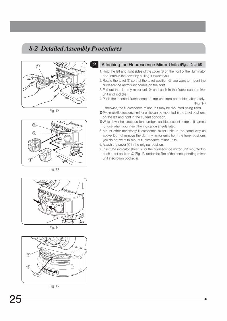
2 Attaching the Fluorescence Mirror Units (Figs. 12 to 15)
1. Hold the left and right sides of the cover @ on the front of the illuminator and remove the cover by pulling it toward you.
2. Rotate the turret 3 so that the turret position 2 you want to mount the fluorescence mirror unit comes on the front.
3. Pull out the dummy mirror unit | and push in the fluorescence mirror unit until it clicks.
4. Push the inserted fluorescence mirror unit from both sides alternately. (Fig. 14)
Otherwise, the fluorescence mirror unit may be mounted being tilted.} Two more fluorescence mirror units can be mounted in the turret positions
on the left and right in the current condition.} Write down the turret position numbers and fluorescent mirror unit names
for use when you insert the indication sheets later.5. Mount other necessary fluorescence mirror units in the same way as
above. Do not remove the dummy mirror units from the turret positions you do not want to mount fluorescence mirror units.
6. Attach the cover @ in the original position.7. Insert the indicator sheet 5 for the fluorescence mirror unit mounted in
each turret position 2 (Fig. 13) under the film of the corresponding mirror unit inscription pocket 6.
1
4
3
2
5
6

26 27
Fig. 16
Fig. 17
1. Loosen the socket clamping screw @ using the Allen screwdriver.2. Hold the upper section of lamp housing and pull it upward to remove
the socket section.
To prevent malfunctions, do not hold the lamp housing by the centering knobs 2.
3. Place the socket section upside down as shown in Fig. 17.} The lamp housing is equipped with the holder for transportation in the
factory shipment condition, or with an old burner when the burner is replaced. Remove the holder or old burner by loosening the two burner holding screws 3
4. Attach the + (positive) pole of the mercury burner | to the fixed mount on the upper side, then the − (negative) pole to the mount on the lower side.
· Be sure to use the USH-103OL (mfd, by OLYMPUS) burner. · Be careful and avoid leaving fingerprints or contaminants on
the mercury burner. Otherwise, there is a danger of explosion due to distortion of glass caused by the stains. If the burner is contaminated, clean it by wiping gently with gauze slightly moistened with absolute alcohol.
5. Attach the socket section with burner to the original position and tighten the clamping screw @.
· Align the external edges of the lamp housing with those on the socket section, and push the lamp housing straight down-ward.
· Attach the lamp housing on the lamp housing installation po-sition of the microscope system so that the heat radiating fins face upward. To prevent a fire hazard, reserve ample spaces above, below and on the rear of the lamp housing.
· Do not light the mercury burner while it is not mounted on the microscope because the UV rays in its light are harmful to your eyes.
· The UV rays in the light of the mercury burner may damage the specimen if this is sensitive to UV rays.
1
2
CAUTION
CAUTION
CAUTION
CAUTION
USH-103OL : 300 hours } This value assumes light cycles composed of 2 hours of
lighting and 30 minutes of extinction. Do not turn it on and off at a shorter cycle than the above, for this will shorten the service life of the burner.
After replacing the burner, reset the hour counter of the power supply unit to “0.0.”
Burner Service Life
43
3 Attaching the Mercury Burner and (Figs. 16 & 17) Lamp Housing5
6. Connect the connector of the lamp house to the power unit U-RFL-T.7. Connect the power cord to the power unit, and insert the power plug into
the outlet.

26 27
Making an Optional Fluorescence Mirror Unit
} You can also fabricate original fluorescence mirror units by fitting a commercially available barrier filter, excitation filter or dichroic mirror in the U-FF empty mirror unit frame.
Dimensions of Optical Parts
· Barrier filter · Excitation filter · Dichroic mirror
When disassembling and assembling the fluorescence mirror unit, place it so that the barrier filter frame comes on the top (as shown above) and handle it by taking care not to stain it with fingerprints, etc.
1. Disassemble the fluorescence mirror unit by lifting up the absorption filter frame.2. Fix the absorption filer in the absorption filter frame and the excitation filter in the main body respectively. Place each
filter by aligning the directions of the arrows located on the side surfaces toward the absorption filter frame and the main body respectively.
Fit the holder ring driver into the groove of the holder ring driver, and fix it by rotating the filter holder ring.} If the filter holder rings may exceed the absorption filter frame or the main body depending on the filter thickness, re-attach
the filter by placing the filter holder ring upside down. 3. Place the main body on the table as shown in the figure, and place the dichroic mirror on it gently.4. Move the absorption filter frame gently back to the original position.
Diameter 25 -0.1/-0.2 mm, max. thickness 6 mm.
26 -0.1/-0.3 x 38 -0.1/-0.3 mm, thickness 1 ±0.05 mm
Holder ring driver
Filter holder ring
Barrier filter frame
Main body
Barrier filter
Dichroic mirror
Interference film surface
Filter holder ring
Holder ring driver
Excitation filter
CAUTION

28 29
LAMP HOUSING INSPECTION SHEET
{ Study the instruction manual for the lamp housing before inspection.{ For safe use of the lamp housing, we recommend performing the following inspection periodically (every time you replace the
mercury burner and at least every 6 months).{ The table below identifies the check items to be observed. Put (X) if not applicable or ( ) if applicable.{ If there is any ( ) mark noted, immediately stop use of the product, and contact Olympus for detailed inspections or replace
the lamp housing.{ If you detect an abnormality other than that listed below or with other Olympus product, also stop the use of the product and
contact Olympus for detailed inspections.{ Note that the service, replacement and detailed inspections are charged after expiration of the warranty period.
If you have any questions, please contact Olympus.
Check results (Date)
Check items / / / /
1. More than 8 years have passed since original purchase or the total power ON time has exceeded 20,000 hours.
2. Illumination flickers when you move the lamp cable or lamp housing.
3. Lamp cable is unusually hot to the touch.
4. Scorching or burning odor is produced during use.
5. Deformation, backlash, or looseness, etc. when you assemble the lamp housing. (Impossibility of removing the top section of lamp housing when you attempt to replace the lamp bulb, etc.)
6. Discoloration, deformation or cracking of the lamp housing.
7. Melting, crack, deformation or solidification of the lamp cable or a wiring part.
8. Increased frequency of servicing compared to similar devices put into use at the same time as the lamp housing.
* When the Check Result columns become insufficient, copy this sheet.
9

28 29
n PROPER SELECTION OF THE POWER SUPPLY CORD
If no power supply cord is provided, please select the proper power supply cord for the equipment by referring to “ Specifications ” and “ Certified Cord ” below:CAUTION: In case you use a non-approved power supply cord for Olympus products, Olympus can no longer warrant the
electrical safety of the equipment.
Specifications
Voltage RatingCurrent RatingTemperature RatingLengthFittings Configuration
125V AC (for 100-120V AC area) or, 250V AC (for 220-240V AC area)6A minimum60˚C minimum3.05 m maximumGrounding type attachment plug cap. Opposite terminates in molded-on IEC configuration appliance coupling.
Table 1 Certified Cord
A power supply cord should be certified by one of the agencies listed in Table 1 , or comprised of cordage marked with an agency marking per Table 1 or marked per Table 2. The fittings are to be marked with at least one of agencies listed in Table 1. In case you are unable to buy locally in your country the power supply cord which is approved by one of the agencies mentioned in Table 1, please use replacements approved by any other equivalent and authorized agencies in your country.
Country AgencyCertification
Mark Country AgencyCertification
Mark
Argentina IRAM Italy IMQ
Australia SAA Japan JET, JQA, TÜV,UL-APEX/MITI
Austria ÖVE Netherlands KEMA
Belgium CEBEC Norway NEMKO
Canada CSA Spain AEE
Denmark DEMKO Sweden SEMKO
Finland FEI Switzerland SEV
France UTE United Kingdom
ASTABSI
Germany VDE U.S.A. UL
Ireland NSAI

30
Table 2 HAR Flexible Cord
APPROVAL ORGANIZATIONS AND CORDAGE HARMONIZATION MARKING METHODS
Approval Organization
Printed or Embossed Harmoni-zation Marking (May be located on jacket or insulation of internal wiring)
Alternative Marking Utilizing Black-Red-Yellow Thread (Length of color section in mm)
Black Red Yellow
Comite Electrotechnique Belge(CEBEC) CEBEC <HAR> 10 30 10
Verband Deutscher Elektrotechniker(VDE) e.V. Prüstelle <VDE> <HAR> 30 10 10
Union Technique de I´Electricite´(UTE) USE <HAR> 30 10 30
Instituto Italiano del Marchio diQualita´ (IMQ) IEMMEQU <HAR> 10 30 50
British Approvals Service for ElectricCables (BASEC) BASEC <HAR> 10 10 30
N.V. KEMA KEMA-KEUR <HAR> 10 30 30
SEMKO AB Svenska ElektriskaMaterielkontrollanstalter SEMKO <HAR> 10 10 50
Österreichischer Verband fürElektrotechnik (ÖVE) <ÖVE> <HAR> 30 10 50
Danmarks Elektriske Materialkontroll(DEMKO) <DEMKO> <HAR> 30 10 30
National Standards Authority of Ireland (NSAI) <NSAI> <HAR> 30 30 50
Norges Elektriske Materiellkontroll(NEMKO) NEMKO <HAR> 10 10 70
Asociacion Electrotecnica YElectronica Espanola (AEE) <UNED> <HAR> 30 10 70
Hellenic Organization forStandardization (ELOT) ELOT <HAR> 30 30 70
Instituto Portages da Qualidade(IPQ) np <HAR> 10 10 90
Schweizerischer ElektroTechnischer Verein (SEV) SEV <HAR> 10 30 90
Elektriska Inspektoratet SETI <HAR> 10 30 90
Underwriters Laboratories Inc. (UL) SV, SVT, SJ or SJT, 3 X 18AWG Canadian Standards Association (CSA) SV, SVT, SJ or SJT, 3 X 18AWG

30
MEMO


M-03