reflection correction for high accuracy transmittance ... · light; and where the upper and lower...
TRANSCRIPT

- ---- ------ ------
JOURNAL OF RESEARCH of the National Bureau of Standards - A. Physics and Chemistry Vol. 77A, No.6, November- December 1973
Reflection Correction for High-Accuracy Transmittance Measurements on Filter Glasses
K. D. Mielenz and R. Mavrodineanu
Institute for Materials Research, National Bureau of Standards, Washington, D.C. 20234
(July 27, 1973)
Multiple reflections in the sample compartment of a spectrophotometer constitute a source of systematic bias in transmittance measurements on filter glasses. This bias may be removed by applying a numerical correction obtained from measurements on tilted samples in polarized light. For a highaccuracy spectrophotometer, this correction was found to be of the order of several 10 - ' transmittance units , independent of polarization , but slightly wavelength dependent.
Key words : Correction for reflections; reflections, multiple; spectrophotometry, high accuracy; systematic bias in spectrophotometry; transmittance, correction.
1. Introduction
The sample compartment of most spectrophotometers is designed such that the monochromator exit slit is focused into the sample by a lens , and is refocused into the detector by another lens (fig. 1). This beam geometry is preferred by instrument designers for intensity reasons and other convenience gains, but may constitute a source of significant systematic errors of the measured data. One of these errors is caused by multiple reflections between the two lenses and the sample surfaces [1,2 , 3]. I
For high-accuracy applications thi s error can be eliminated by means of a numerical correction, aT, which converts the measured transmittance, TM ,
into the correct value
T = T.\/+aT. (1)
I Figures in brackets indicate the literature re ferences at the end of this paper.
EX IT SLIT
A simple but accurate method to determine this correction is described in this paper.
The specific spectrophotometric application discussed is the measurement of the transmittance of glass filters to an accuracy of ± 10- 4 transmittance units. For the particular high-accuracy spectrophotometer used [4], the correction aT was found to be of the order of several 10- 4 transmittance units, independent of polarization throughout the visible spectrum, and applicable for filters with widely different indices of refraction. The correction was found to be slightly wavelength dependent.
2. Theoretical Background
A detailed discussion of the reflection errors affecting the measurement of filter transmittances may be found in reference [3]. A summary is given here in order to provide the theoretical foundation for the experimental work described in section 3.
SA MPLE
DE TE CTOR ENTRANCE APERTURE
FIGURE 1. Sample-compartment optics oj a focused-beam spectrophotometer.
699
---------
The purpose of the measurement is assumed to be the determination of the normal-incidence transmittance,
(2a)
of a glass filter surrounded by air. The filter is characterized by its thickness t and complex refractive index n (1 + iK), so that for each wavelength A the normal-incidence internal transmittance 7i and Fresnel reflectance r appearing in eq (2a) are given by
7j = e-47r1tKt/ )", (2b)
r=(:;;r (2c)
This quantity 7 can be measured accurately with specially designed instrumentation in which the sample is placed normal to a collimated beam of light, the collimation being effected by off-axis mirror optics in a manner which reduces reflection errors to a negligible level [3, 5]. A conventional spectrophotometer does not permit such a direct measurement of 7 because of the above-mentioned reflection error, even if its lenses were arranged to produce a collimated rather than the usual focused beam.
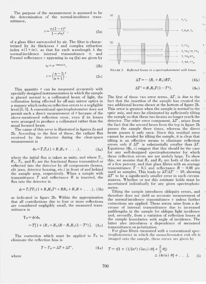
The cause of this error is illustrated in figures 2a and 2b. According to the first of these, the radiant flux received by the detector during the clear-space measurement is
where the initial flux is taken as unity, and where T1 ,
R 1, T2 , and R2 are the fractional fluxes transmitted or reflected into the detector by all components (lenses, slit jaws, detector housing, etc.) in front of and behind the sample area, respectively. When a sample with transmittance T and reflectance R is inserted, the flux into the detector is
as indicated in figure 2b. Within the approximation that all contributions due to four or more reRections are considered negligibly small, the measured transmittance is
TM=c/J/c/Jo
=T[I+(R 1 +R2)R-R 1R2(I-T2)]. (3c)
The correction which must be applied to TM to eliminate the reflection bias is
T- TIIf = !1T+!1T', (4a)
where
(0)
~ ~ '" -,: ,
' '-< I
I 0.
Ib) (
1 ~ ~ t- \,
T, TR2 TR, TT 2
T,TR 2 RT 2
FIGURE 2. Reflected beams in a spectrophotometer with lenses.
!1T=- (R 1 + R2)RT,
!1T' = R lR2T(l- TZ).
(4b) .J
I
(4c) I
The first of these two error terms, !1T, is due to the fact that the insertion of the sample has created the two additional beams shown at the bottom of figure 2b. This error is greatest when the sample is normal to the >
optic axis, and may be eliminated by sufficiently tilting the sample so that these two beams no longer reach the detector. The other error component, !1T' , arises from the fact that the second beam from the top in figure 2b passes the sample three times, whereas the direct 1 beam passes it only once. Since this residual error cannot be avoided by tilting the sample, it is clear that I tilting is an effective means to eliminate reflection errors only if !1T' is substantially smaller than !1T. Equations (4b, c) suggest that this should be the case for any well-designed spectrophotometer for which these reflection errors are not unduly large. To show this, we assume that Rl and R2 are both of the order of a few percent, and that glass filters with an average ~ transmittance T ~ 0.5 and reflectanCf~ R ~ 0.08 are I
used as samples. This leads to !1T/!1T' ~ 10, showing 1 !1T' to be a significantly smaller error in such circumstances. Whether or not this estimate holds must be ascertained individually for any given spectrophotometer.
Tilting the sample introduces obliquity errors, and ); therefore does not yield an accurate measurement of the normal-incidence transmittance 7 unless further corrections are applied. These errors arise from a decrease of internal transmittance due to increased pathlengths in the sample for oblique light incidence and, secondly, from a variation of reflection losses at the sample boundaries with angle of incidence. The latter also introduces a dependence of measured transmittance on polarization.
For glass filters measured with a conventional sp"ctrophotometer in which the monochromator exit slit is imaged onto the sample , these errors are given by
2 T = 7[1 + (l/2n 2 ) (JUT;) (e~+"3 e~)
± (4r/n) e~+ . .. ], (5)
700

where T is the measured transmittance (corrected for reRection errors); T, Ti, and r are the normal-incidence values of transmittance, internal transmittance, and Fresnel reRectance as given by eqs (2a, b, c); (JT and
~ (Jo are the tilt angle and the cone angle of the incident light; and where the upper and lower signs of the last term pertain to the two cases in which the light is S or P polarized in the tilt plane. Equation (5) was
" derived in reference [3] under the assumption that the I monochromator exit slit is sufficiently short to approxi-, mate a point source, and that the focusing lens is under-
filled so that the grating or prism constitutes the limiting aperture. This aperture is assumed to be square, subtending the same angle 2(Jo in the horizontal and vertical planes. The sample is assumed to be tilted only
" in one of these planes. The small-angle approximation given in eq (5) is estimated to be accurate to 10-4
transmittance units for angles (JT and (Jo up ·to about 100 •
For average transmittances and tilt angles of a few degrees, these obliquity effects are of the order of 10-3 transmittance units. Since this is the same magnitude as estimated above for the reRection error, it is
!. . clear that for a spectrophotometer with lenses an accurate measurement of the normal-incidence transmittance T cannot be achieved without numerical correction for either source of error. If the sample is tilted in order to reduce the reflection error, an obliquity correction must be applied. Vice versa, a reflection correction is necessary if the sample is normal to the optic axis so that obliquity effects are minimized. Although these two alternatives are equivalent, the latter was chosen in this work since it constitutes the simpler approach for routine measurements of transmittance.
3. Experimental Procedure
The preceding theoretical discussion does not permit a precise calculation of the required reRection correction. Representing fractional fluxes which actually reach the detector, the quantities RJ and R2 appearing in equations (4b, c) are complicated and generally unknown functions of the relative positions of sample compartment elements, lens curvatures, location of aperture stops, and other beam-geometry factors. This makes it necessary to measure thp. correction. Such a measurement may be performed as follows.
Each of a series of filters with different transmittances is measured for different known tilt angles (Jr, and for Sand P polarization of the incident light. This yields a set of raw data T M, such as plotted in figure 3a. These are transformed into corrected data T by adding the tilt-correction given by eq (5),
where the approximate values TAt and T At/ (1- 2r) were substituted for T and Ti on the right-hand side, and where estimates of nand r may be used. As indicated by figure 3b, these corrected transmittances T are constant for sufficiently large positive or negative tilt
.557 x/~·"~\x x/I- -x~x_ .556 -x--x--/ . s
50' 'f /0 \ 50' /
/
•
(a) --e~
.553 '--_-'--___ -'--___ -'--___ -'--___ -'--_
T
.557 i x~'x f ~/. ·~x -LIT
.---~/ . .~ x t x x x
.556 (b) -e~
-8 -4 0 4 8
FIGURE 3. (a) Measured transmittance T M versus tilt angle ()T
for 55 percentjilter in S andP polarized light at A = 574 nm. (b) The same data after application of tilt correction.
angles, but near normal incidence exhibit the 'reflection hump' whose height represents the desired reflection correction Ll T to be applied for this particular value of transmittance. From the measurements performed on all of the filters one may then determine the dependence of Ll T on T, as illustrated by figure 4. According to eq (4b), this dependence should be linear. In the work described here , these measurements were made as follows.
A series of four Schott NG-4 glass filters with nominal transmittances 0.1,0.2,0.3, and 0.5 , an evaporated metal·on-glass filter with a nominal transmittance 0.4, and a clear glass plate were used. All of these samples were 50 mm X 50 mm X 2 mm in size, and Rat and plane· parallel to within a few fringes of mercurygreen light. The spectrophotometer used to perform the measurements was fully described in a previous issue of this journal [4], and will not be discussed here_ The filters were placed in the sample compartment of this spectrophotometer on a vertical rectangular holder adapted to a rotary horizontal table with 10 cm diameter. This table had a scale divided in 3600 with a vernier reading to 5 min, and was held on the singlesample carriage of the spectrophotometer (see ref. [4], fig. 2) with a vertical mounting rod_ This sample carriage unit consists of a platform provided with vertical holders which can be moved laterally by a
701
---------- - - -

1.0
• 0.5
• • -T
O~ ____________ ~ ____________ ~ ___
o 0.5 1.0
FIGURE 4. Reflection correction 6. T versus T for A =574 nm.
rack and pinion arrangement. The platform, mounted on four ball bushings which ride on two horizontal rods, can be moved pneumatically across the optical axis. This remote-controlled movement is smooth, and the sample position in and out of the beam is reproducible within 0.025 mm.
A sheet polarizer of 9.5 cm diam was used to produce the Sand P polarized radiation. This polarizer was held in a ball bearing rotating mount with a circular scale divided from 0 to 360°. It was placed on the optical bench in front of the entrance slit of the predisperser-monochromator aggregate of the spectrophotometer between the circular neutral wedge and the flat front-surface mirror (see ref. [4], fig. 3). This placement of the polarizer on the source side of the spectrophotometer avoids the additional reflection errors which would occur if the polarizer were put in the sample compartment of the spectrophotometer, but requires that the monochromator does not significantly depolarize the incident radiation or rotate its plane of polarization. This was ascertained by testing the monochromator between crossed polarizers at the wavelengths at which the measurements were performed.
Each transmittance measurement was performed in Sand P polarized radiation and for tilt angles varying by ± 10° about the normal position. Each measurement resulted from the ratio 1110 of the attenuated to the un attenuated radiation value, each I and 10 being the average of 50 individual measurements. The measurements were repeated four times.
4. Results
Using the procedures outlined In section 3, the numerical values of the reflection correction !:l.T were determined for the four neutral-density glass
filters and the clear glass plate, at the wavelength >-. = 574 nm. This yielded the result represented by the straight line in figure 4; namely,
!:l.TIT = -8.9X 10⁻⁴, for >-.=574 nm. (7 a)
Each of the individual values of !:l.T could be measured to a precision better than 10- 4 transmittance units. There was no evidence suggesting a dependence of ' !:l.T on polarization. ,
Secondly, the measurements on the clear glass di plate were repeated for >-. = 400 nm and 650 nm. Together with the previously obtained result for 574 nm, this showed the wavelength dependence indicated in figure 5_ This dependence is also linear, . 1 and may be expressed as I
!:l.T/T=-1.26 X 10- 6 (>-, -574 nm), for T=O.92. (7b)
These results were then combined into the final empirical expression.
!:l.TIT = -8.9 X 10- 4 [1 + 1.4 X 10- 3 (>-' -574 nm)] , (8)
for the correction jj.T to be applied for different transmittances T and wavelengths >-.. This formula agrees with all individual measurements of !:l.T to within ± 5 X 10- 5 transmittance units.
The correction fiT so obtained represents only the first of the two error terms appearing in eq (4a), above. The exact value of the second term !:l.T' cannot be determined within the context of this paper, but a quantitative estimate may now be obtained as follows. From eqs (4b) and (7a) it may be seen that, for this spectrophotometer and for the appropriate value R - 0.08 for the filters used,
(9a)
Provided that this arithmetic average of Rl and R2 is not substantially different from their geometric average (R 1R2 )1/2 ,it follows from eq (4b) that
!:l.T' - 3.6 X 10- 5 T(l- T2), (9b)
I I I I 1.2f- -(6T1T) X 10-3 -
i ~
O.8~
1.0f-
-
0.6 '--.l...-1 ____ -'1 _____ -'-:-1 ____ ="~'-:-' 400 500 600 700
FIGURE 5. Reflection correction 6. T versus A for T = 0.92
t:
I
702

or tJ.T' - 1.4 X 10⁻⁵ for T= 0.577, for which this ~ ~. error is a maximum. Although this argument is not
mathematically exact, it suggests that the residual " reflection error tJ.T' is entirely negligible for the
spectrophotometer used here. According to eq (4b), the correction AT depends on
the reflectance R and, therefore, on the refractive index n of the sample. Using eqs (4b) and (2c) it is easily seen
f · that
d( AT) = _ 8r(R t + R 2 )T d u (n+ 1)2 n. (10)
For n = 1.5, r = 0.04, T = 0.5, and the above value (9a) for (R t + R 2 ), this is reduced to d(AT) - 3 X 10- 4
dn; showing that AT will not be affected by more than 10-4 transmittance units as long as dn < 0.3, or 1.2 < n < 1.8. Hence it may be concluded that the above values of AT are applicable to virtually all filter glasses. Other types of samples, such as coated glasses, will of course require a different correction. For example, measurements on the evaporated metal,on·glass filter with transmittance 0.4 at 474 nm yielded a value, AT = - 1.4 X 10⁻³ , which is about four times larger than indicated by figure 3 for uncoated samples.
S. Conclusion
Based upon this work, all transmittance measure, ments on glass filters with this high,accuracy spectro' photometer are performed with the sample accurately aligned normal to the optic axis. In addition to the re' flection correction given by eq (8) and the detector nonlinearity correction discussed in reference [4], an/number correction is applied to remove the resid· ual bias due to the nonparallel radiation in the sample compartment. This latter correction is given by eq (5) as
its magnitude is 1.3 X 10⁻⁴ transmittance units, or less, for the 1/10 cone of light (60 =0.05 rad) used. With these corrections applied, all measurements made with this high,accuracy spectrophotometer yield the normal, incidence transmittance T defined by eq (2a) within a 10-4 limit of instrumental accuracy.
This spectrophotometer was designed and con· structed to permit calibration of solid and liquid filters for transmittance with a well,defined accuracy (4). These filters are used as Standard Reference Materials (SRM's) to check the photometric scale of conventional spectrophotometers. SRM 930a consists of a set of three glass filters (Schott NG-4) with nominal trans· mittances 0.1, 0.2, and 0.3. Their transmittance values are certified to ± 0.5 percent of the value, this uncer' tainty being the sum of random and systematic errors. The latter are principally due to the inherent inhomogeneity and , instability of the glass, surface effects, and positioning the filters. They exceed by a large margin the instrumental corrections discussed in this paper. Hence, the certified transmittances of previously issued standard filters remain unaffected by these corrections.
6. References
[1] Gibson, K 5. , and Balcom, M. M. , J. Res . Nat. Bur. Stand. (U.S.), 38, 601 (1947).
[2] Goldring, L. 5. , Hawes, R. C. , Hare, G. H. , Beckman , A. 0 ., and Stickney, M. E., An al. Chern. 25,869 (1953).
[3] Mielenz, K D., J. Res. Nat. Bur. Stand. (U.S.), 76A (phys. and Chern.), No.5, 455-467 (Sept.-Oct. 1972).
[4] Mavrodineanu , R., J. Res. Nat. Bur. Stand. (U.S.) , 76A (phys. and Chern.), No.5, 405-425 (Sept.-Oct. 1972).
[5] Mielenz, K D. , Eckerle, K. L. , Madden , R. P ., and Reader, J., Appl. Optics 12, 1630 (1973).
(Paper 77A6-792)
703
l (