reflux classifiers
TRANSCRIPT

Knowledge Piece On
Reflux Classifier
BY Utsav Kant
Manager Operation (W#3)157800
09-09-2013
1
Introduction
A reflux classifier is a fluidised bed separator forclassifying and separating particles on the basisof size or density .
Reflux Classifier is a combination of a fluidisedbed separator, an autogenous dense mediumseparator and a lamella settler
2
Basic Chambers of Reflux classifier
The machine consists of Lamella Chamber,Mixing Chamber and Fluidisation Chamber
Upper Chamber is the Lamella Chamber, MiddleChamber is the Mixing Chamber, Bottom mostchamber is the Fluidisation Chamber
3
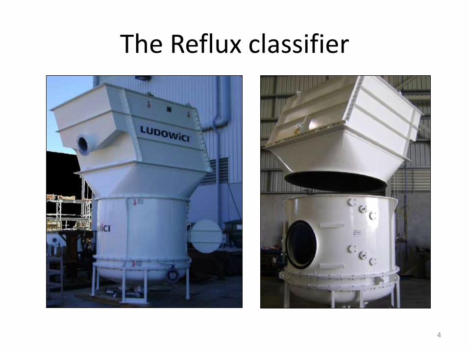
The Reflux classifier
4
Mixing and Fluidisation Chambers
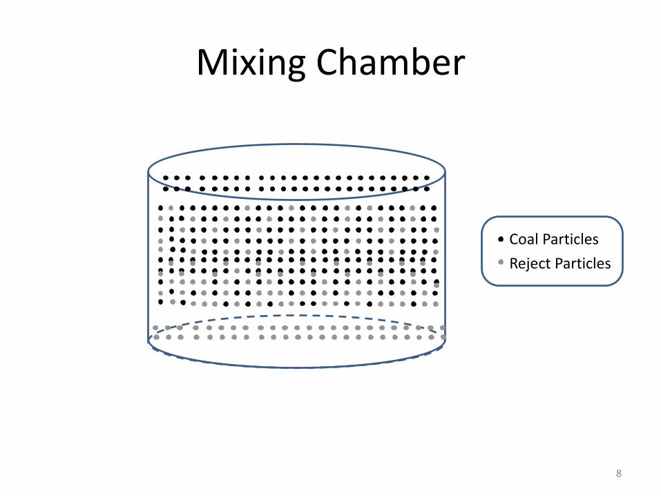
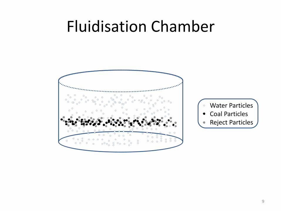
Reflux Classifier feed is introduced to theMixing Chamber via two square chutesextending trough the lamella section. At thebase of the mixing chamber, high pressurefluidisation water is introduced via 390alumina ceramic nozzles and flows upwardsinteracting with the slurry. The underflow isdrained from the bottom-centre of thefluidisation chamber via an automaticallycontrolled underflow valve
5
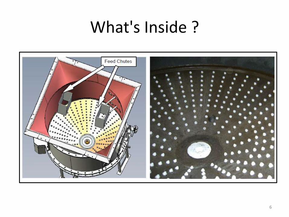
What's Inside ?
6
Phenomena in the Mixing chamber
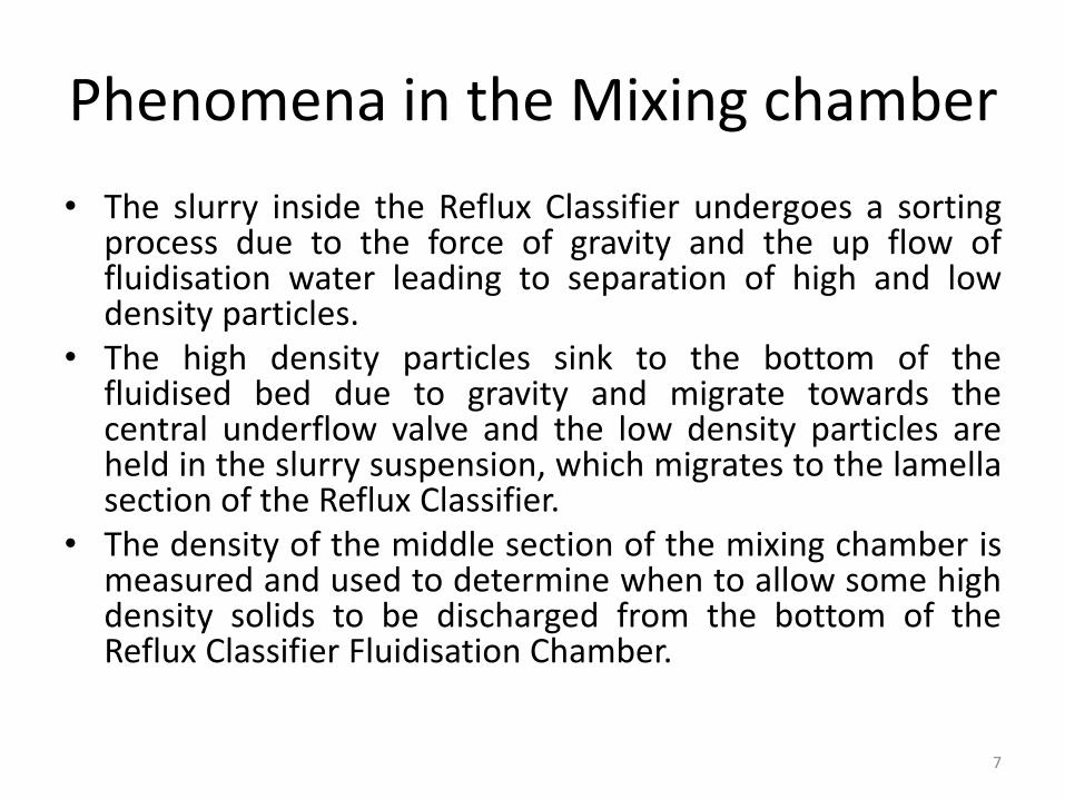
• The slurry inside the Reflux Classifier undergoes a sortingprocess due to the force of gravity and the up flow offluidisation water leading to separation of high and lowdensity particles.
• The high density particles sink to the bottom of thefluidised bed due to gravity and migrate towards thecentral underflow valve and the low density particles areheld in the slurry suspension, which migrates to the lamellasection of the Reflux Classifier.
• The density of the middle section of the mixing chamber ismeasured and used to determine when to allow some highdensity solids to be discharged from the bottom of theReflux Classifier Fluidisation Chamber.
7
Mixing Chamber
Coal Particles
Reject Particles
8
Fluidisation Chamber
Water ParticlesCoal ParticlesReject Particles
9
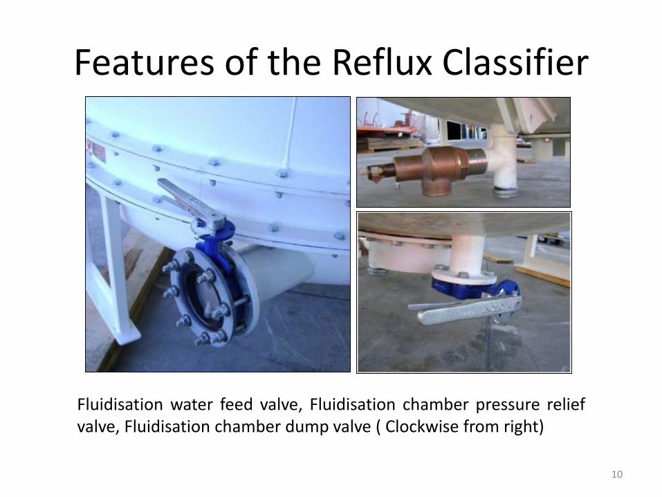
Features of the Reflux Classifier
Fluidisation water feed valve, Fluidisation chamber pressure reliefvalve, Fluidisation chamber dump valve ( Clockwise from right)
10
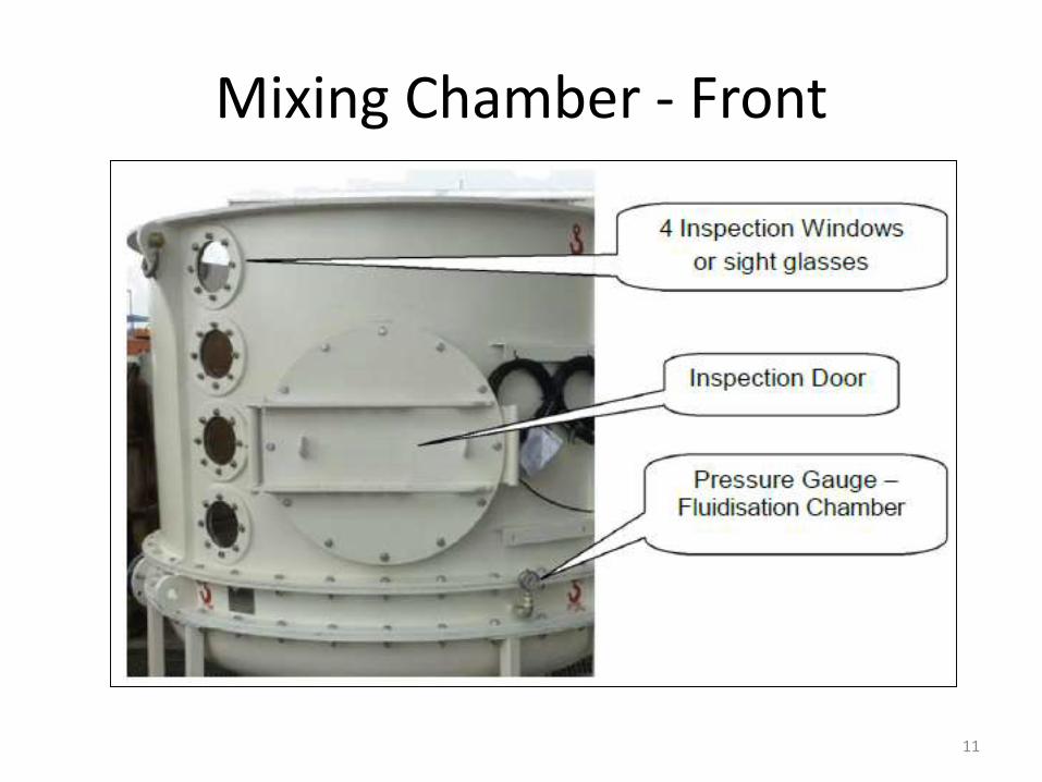
Mixing Chamber - Front
11
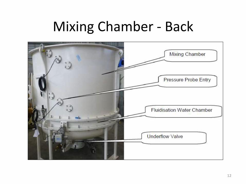
Mixing Chamber - Back
12
Lamella Chamber
• Arrays of inclined plates form lamellae and dividethe chamber into zones into which particles ofpredetermined size or density migrate. Particledifferentiation is controlled by plate length,inclination and spacing in each array, combinedwith fluidization rate.
• The addition of parallel inclined plates towardsthe overflow section improves sedimentationarea, resulting in increased throughput comparedto conventional separators.
13
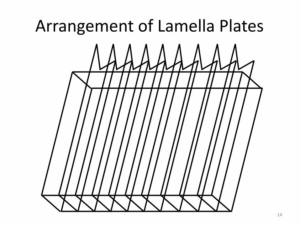
Arrangement of Lamella Plates
14
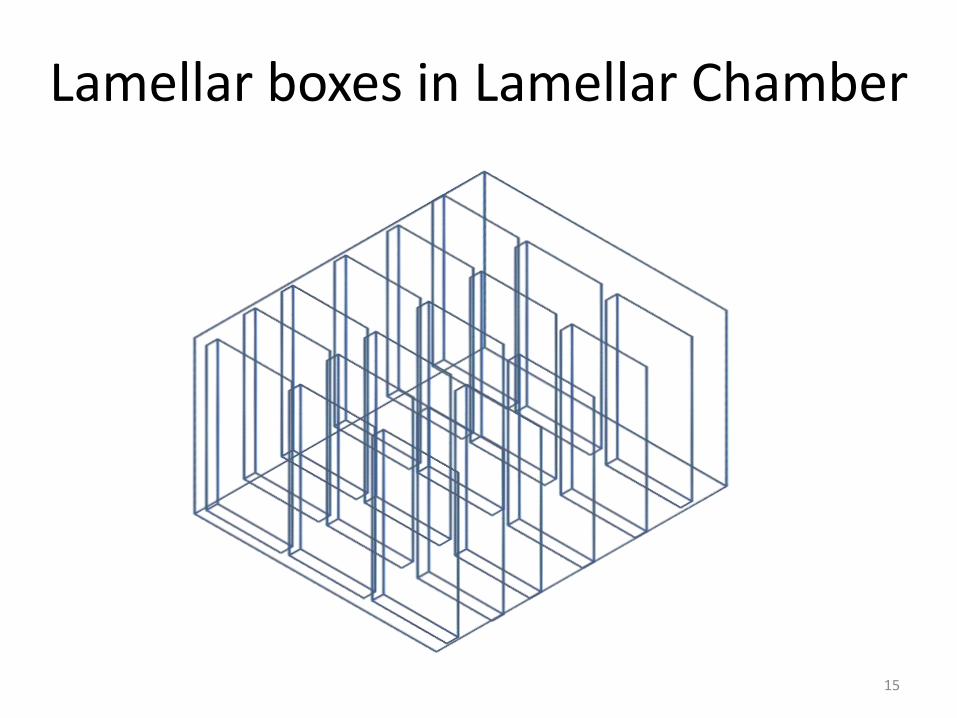
Lamellar boxes in Lamellar Chamber
15
Phenomena in Lamella chamber
• The lamella channels enhance the settling rate of anymisplaced high density solids, which slide down theplates and slowly re-circulate back into the feed zoneof the mixing chamber. This forms a slightly higherdensity zone under the lamella plates.
• The low density and small particles tend to overflowfrom the Reflux Classifier Lamellas in their first pass,whereas the slightly denser and larger particles willrequire the autogenous process density within thevessel to rise to enable them to be displaced tooverflow.
16
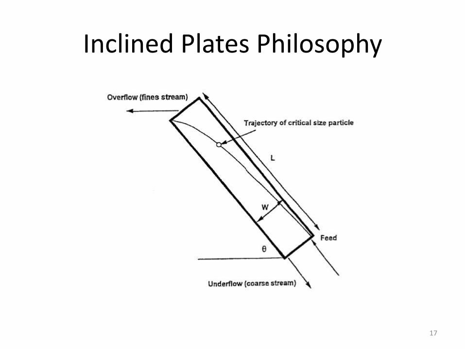
Inclined Plates Philosophy
17
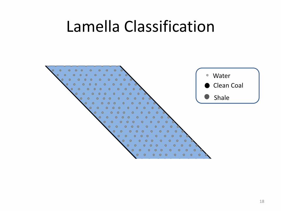
Lamella Classification
Water
Clean Coal
Shale
18
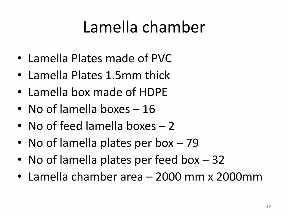
Lamella chamber
• Lamella Plates made of PVC
• Lamella Plates 1.5mm thick
• Lamella box made of HDPE
• No of lamella boxes – 16
• No of feed lamella boxes – 2
• No of lamella plates per box – 79
• No of lamella plates per feed box – 32
• Lamella chamber area – 2000 mm x 2000mm
19
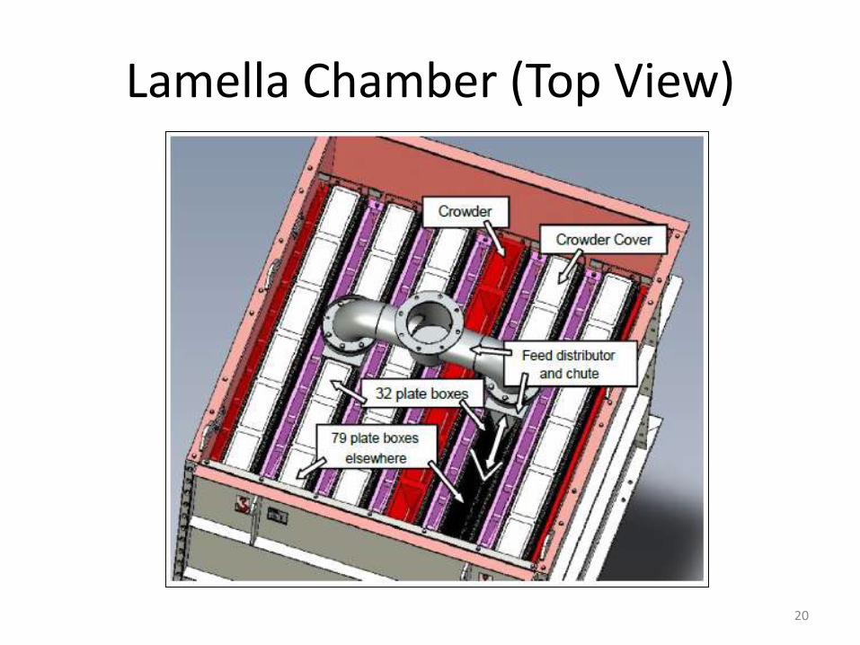
Lamella Chamber (Top View)
20
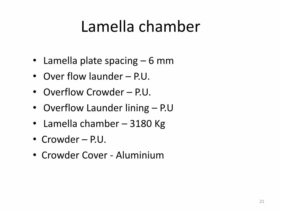
Lamella chamber
• Lamella plate spacing – 6 mm
• Over flow launder – P.U.
• Overflow Crowder – P.U.
• Overflow Launder lining – P.U
• Lamella chamber – 3180 Kg
• Crowder – P.U.
• Crowder Cover - Aluminium
21
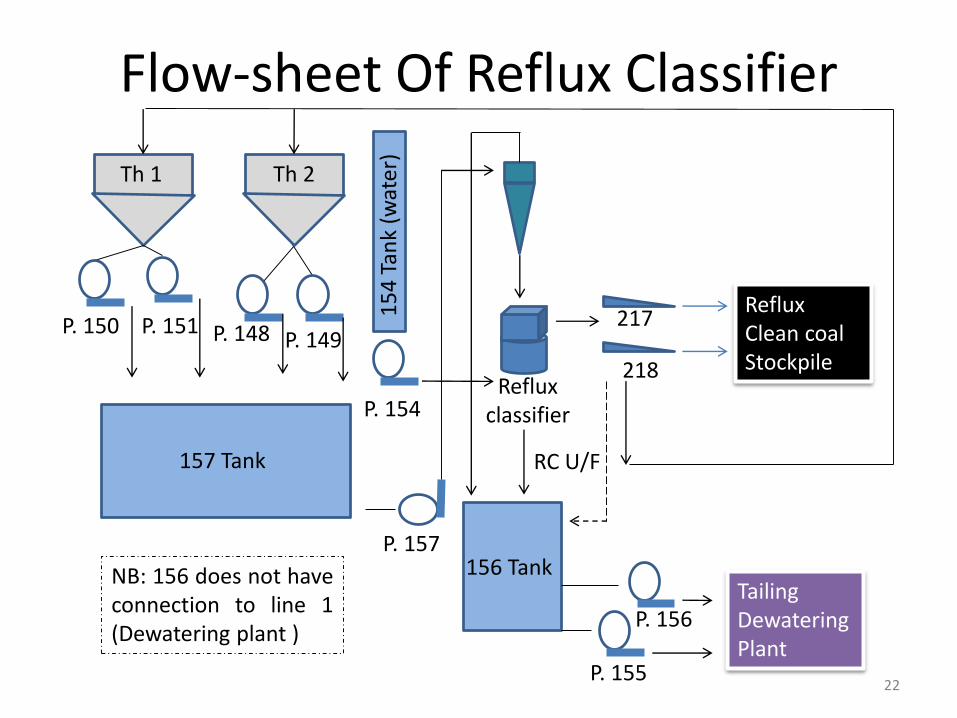
Flow-sheet Of Reflux Classifier
Th 1 Th 2
P. 150 P. 151 P. 148 P. 149
157 Tank
P. 157
Reflux classifier
156 Tank
P. 155
P. 156Tailing Dewatering Plant
217
218
RC U/F
Reflux Clean coalStockpile
NB: 156 does not haveconnection to line 1(Dewatering plant )
22
P. 1541
54
Tan
k (w
ater
)
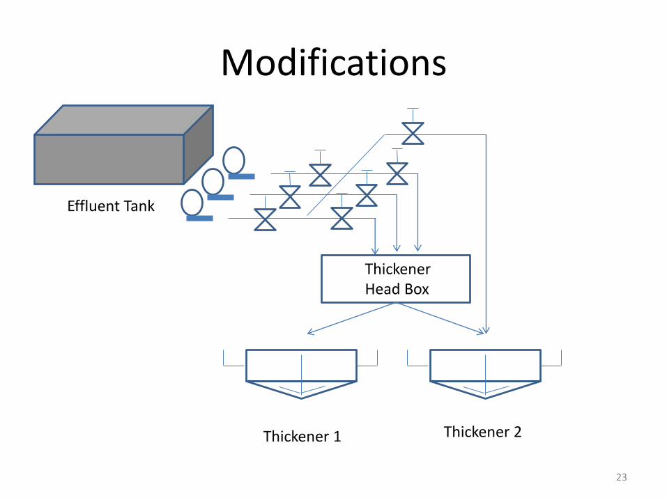
Modifications
Thickener 2Thickener 1
Thickener Head Box
Effluent Tank
23