reformer furnace outlet systems · reformer furnace outlet systems ... including ammonia plant...
TRANSCRIPT

BD Energy Systems, LLC.
Reformer Furnace Outlet Systems Design Considerations, Emergency Repair, and Enhanced Reliability
Daniel Barnett, Vice President of Engineering
Joe Price, Senior Process Engineer
BD Energy Systems, LLC— S. Dairy Ashford, Houston Texas
T: ‐ ‐ DD: ‐ ‐ E: [email protected]
[First published in “Nitrogen+Syngas” Number 324 ‐ July/August 2013]

Reformer Furnace Outlet Systems | 2
Executive Summary Reformer furnace outlet collection systems operate under severe service conditions that push the metalurgical limits of the
materials used. For that reason, reliable long‐term performance depends strongly on the operational control and
maintenance practices applied by the owners as well as the design margins and inherent robustness of the mechanical
design. Reformer outlet system components are also subject to service‐induced embrittlement due to the formation of
carbides and other compounds which results in loss of repair weldability in the outlet system components and complicates
any need for repair over the life of the system. This paper presents the significant operational and maintenance factors
that influence reformer outlet system reliability, discusses the adequacy of design margins typically applied, the failures
and the repair methods that have been successfully applied when outlet system failures occur, and design features that
can be applied to make the outlet system more robust and therefore more reliable.
CONTENTS
Executive Summary 2
Background - The Issue 3
Temperature / Pressure Limits of Outlet System Materials 3
The Issue Quantified 4
Discussion of Design Margin Adequacy 5
The Problems 7
Common Failures 7
Discussion of Common Repair Techniques 9
Learned Techniques 10
Potential Solutions 11
Operation and Maintenance Improvements 11
Improved Preparation 12
Long‐Term Improvements 13
Conclusions 13

Reformer Furnace Outlet Systems | 3
Background - The Issue Steam‐methane reformer furnaces, or SMRs, are used in a number of common synthesis gas production applications.
These may support the production of Ammonia, Methanol, Gas‐to‐Liquids, Hydrogen, or Reducing Gas. The operating
conditions of each process differ and there is also a range of conditions within each of these production applications
depending on the specific technology used in the plant. However, almost all applications result in outlet system conditions
that challenge the design limits of the materials of construction. In general, ammonia plant reformer furnaces have lower
operating temperatures but significantly higher pressures when compared to methanol and hydrogen applications while
reducing gas applications have lower pressure but even higher temperatures than methanol and hydrogen applications.
The table below shows the typical range of operating conditions for the reformer furnace outlet system for each of these
applications. Note that for the purposes of this comparison we are examining conventional designs therefore, we are not
including ammonia plant applications that incorporate the use of enriched air or excess air to the secondary reformer, nor
are we including methanol plant applications that incorporate the use of an oxygen‐fed secondary reformer.
Table 1 Typical Operating Conditions @ Reformer Furnace Outlet
Process Application Temperature Range (oF)
Pressure Range (psig)
% Methane Slip
%CH4
Conventional NH3 1525 1450 450 600 10 16
Conventional MeOH 1625 1550 250 350 3 7
Hydrogen / GTL 1650 1550 150 300 2 5
Reducing Gas 1750 1650 30 100 0.8 1.0
Temperature / Pressure Limits of Outlet System Materials
The material of choice for outlet pigtails is a wrought 800HT material due to its high strength and relatively high ductility. Mechanically, the pigtail is relied upon to provide the required flexibility within the system to avoid overstress of the end connections of the pigtail to the manifold and to the bottom of the catalyst tube. It also is sometimes pinched as a means to
isolate a tube leak. The use of 800HT material with relatively small diameter of 1 ¼‐1 ½‐ NPS is typically used. Outlet pigtail designs often push up to a
thickness/diameter ratio in the range of 0.15‐0.20
The material of choice for outlet manifolds varies somewhat among the reformer designers based on application. Some lower temperature designs having a design temperature in a range below 1525oF can use either 800HT material or the cast equivalent 20Cr‐32Ni alloy while those designs in a
temperature range above 1525oF tend to use the cast equivalent 20Cr‐32Ni alloy. Outlet manifold designs typically have thickness/diameter ratio closer to 0.10‐0.12 in order to limit thermal stresses through the thickness of the
manifold during temperature cycles.
Manifolds Cast
20Cr‐32Ni
Manifolds
800HT
Pigtails
800HT
Reformer Furnace Outlet Systems | 4
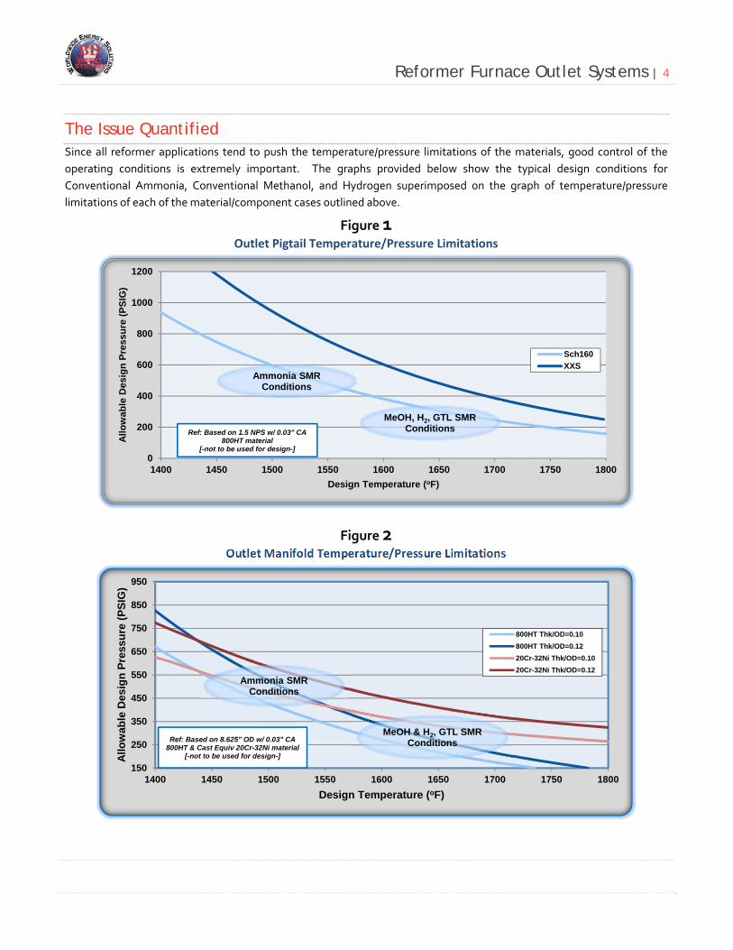
The Issue Quantified Since all reformer applications tend to push the temperature/pressure limitations of the materials, good control of the
operating conditions is extremely important. The graphs provided below show the typical design conditions for
Conventional Ammonia, Conventional Methanol, and Hydrogen superimposed on the graph of temperature/pressure
limitations of each of the material/component cases outlined above.
Figure 1 Outlet Pigtail Temperature/Pressure Limitations
Figure 2 Outlet Manifold Temperature/Pressure Limitations
0
200
400
600
800
1000
1200
1400 1450 1500 1550 1600 1650 1700 1750 1800
Allo
wab
le D
esig
n P
ress
ure
(P
SIG
)
Design Temperature (oF)
Sch160
XXSAmmonia SMR
Conditions
MeOH, H2, GTL SMR ConditionsRef: Based on 1.5 NPS w/ 0.03" CA
800HT material[-not to be used for design-]
150
250
350
450
550
650
750
850
950
1400 1450 1500 1550 1600 1650 1700 1750 1800
Allo
wab
le D
esig
n P
ress
ure
(P
SIG
)
Design Temperature (oF)
800HT Thk/OD=0.10
800HT Thk/OD=0.12
20Cr-32Ni Thk/OD=0.10
20Cr-32Ni Thk/OD=0.12
Ref: Based on 8.625" OD w/ 0.03" CA800HT & Cast Equiv 20Cr-32Ni material
[-not to be used for design-]
Ammonia SMR Conditions
MeOH & H2, GTL SMR Conditions

Reformer Furnace Outlet Systems | 5
Discussion of Design Margin Adequacy Design margins are applied to the operating temperature and pressure to allow for operating flexibility and survival of
operating upsets that may result in short‐term conditions that deviate from normal. For long‐term operations, design
margins also allow tolerance for imperfect flow distribution and heat input among the total population of catalyst tubes.
Uniformity of process flow to all catalyst tubes is confirmed with pressure drop checks carried out at the time of catalyst
loading. These checks confirm pressure drop uniformity within about +/‐5% which translates to a flow uniformity
tolerance of +/‐2.5% when catalyst is loaded using modern catalyst loading methods. However, as the reformer is put
through start‐up/operation/shut‐down temperature cycles the expansion/contraction of the catalyst tube length and
diameter results in some amount of settling and breakage of the catalyst. The greater the number of cycles, the more
catalyst settling and breakage is experienced. Over time this produces additional pressure drop through the catalyst
which is not uniform among all of the tubes. This creates greater deviation in flow uniformity over the life of the catalyst.
Likewise, uniformity of heat input to all of the catalyst tubes is considered to be within +/‐5% when the burners and the
flue gas collection tunnels (or coffins) are new. With operation however, the burner tip orifices can become restricted with
pipe scale or with coke accumulation due to the presence of heavier hydrocarbons and in some cases fuel gas orifices can
become enlarged due to oxidation and erosion. In addition, the dimensional consistency of the flue gas collection tunnels
can deviate over time which can open new flow paths for flue gas into the tunnel from the firebox, causing an imbalance of
flue gas flow in local areas. These factors can lead to a deterioration of heat input uniformity as the reformer ages without
proper attention to the importance of maintenance.
Overall combined heat input and flow uniformity tolerance may therefore start out at +/‐7.5% when the reformer and
catalyst is new but can easily deteriorate to +/‐15% or worse as the catalyst condition and heat input factors deteriorate.
When setting design margins it is important to understand that the temperature margin applied should consider the
reformer furnace application. The significance of this statement is clearly illustrated in the figure below. With reference to
Figure 3, a design temperature allowance of 50oF for conventional Ammonia reforming conditions allows a combined flow
uniformity and heat input uniformity tolerance of +/‐12‐14%. Historical operations have proven this allowance to be
generally acceptable for reliable performance in conventional ammonia service. To achieve a similar level of flow and heat
input uniformity tolerance for conventional methanol or hydrogen operating conditions requires a design temperature
allowance of 100oF or more. The reason for this difference relates to the proportion of incremental heat that is consumed
by additional reforming reaction versus that which goes directly to sensible heat. As previously noted in Table 1, there is a
greater percentage of unreacted methane remaining at the outlet of the catalyst tube (or methane slip) for the
conventional ammonia plant reformer conditions when compared to the unreacted methane remaining for the
conventional methanol and hydrogen conditions. As the remaining unreacted methane approaches zero, a greater portion
of the incremental heat input becomes sensible heat increasing temperature.
It should be noted that most conventional methanol and hydrogen plant reformer furnaces do not have a design
temperature allowance as high as 100oF; therefore, in order to achieve reliable performance they require tighter control of
operating conditions and greater attention to maintaining the condition of the burners and other factors that influence
heat input uniformity.
If we consider that the outlet system, no matter the application, should be designed to provide a relative heat input and
flow uniformity tolerance of +/‐13% then we arrive at a design margin approach as presented in Figure 4. With reference
to Figure 4, Conventional Ammonia reformer conditions with catalyst tube outlet methane slip in the 14‐16% range should
have an outlet system design margin of 50oF, Conventional Methanol reformer conditions with catalyst tube outlet

Reformer Furnace Outlet Systems | 6
methane slip in the 5‐6% range should have an outlet system design margin of at least 75oF, and Hydrogen reformer
catalyst tube outlet methane slip in the 3‐4% range should have an outlet system design margin of at least 100oF in order
to provide the same level of heat input tolerance and reliability.
Figure 3 Relative Heat/Flow Uniformity vs. Outlet Temperature Deviation
Figure 4 Relative Heat/Flow Uniformity vs. Outlet Temperature Deviation
‐150
‐100
‐50
0
50
100
150
‐15% ‐10% ‐5% 0% 5% 10% 15%
Catalyst Tu
be Outlet Temp Deviation [oF]
Relative Heat Input Uniformity Tolerance
2%
3%
4%
12%
16%
MethaneSlip
ConventionalMeOH, H2, & GTL
‐150
‐100
‐50
0
50
100
150
0% 2% 4% 6% 8% 10% 12% 14% 16% 18%
Catalyst Tu
be Outlet Temp Deviation [oF]
Design Methane Slip [% CH4]
13%
10%
5%
‐5%
‐10%
‐13%
Heat InputTolerance
Reformer Furnace Outlet Systems | 7
The Problems With long‐term operation of a reformer furnace, various pressure containing components [outlet reducer cones, pigtails,
collector manifolds, tees, transfer line connection transitions] of the outlet system are subjected to high stresses and creep
damage due to exposure to the temperature and pressure conditions as well as the effects of mechanical support system
deficiencies and deterioration of these supports over time. The design intent of any reformer outlet support system is to
maintain the stresses of all components of the system within their limits as the furnace cycles up in temperature to
operating conditions and back down to ambient conditions during shutdown. To achieve this design intent, the pigtails
must first be designed with sufficient flexibility to keep the stresses at the end connections within the allowable limits, and
the spring supports, fixed and/or sliding supports, and hangers must be designed to carry a consistent load while allowing
unrestricted thermal expansion as the system transitions from ambient conditions up to operating conditions. It is very
important that the support system provide consistent long‐term support of the loads over the life of the furnace. When
the support system fails to provide proper support of loads, any unsupported load is transmitted through the outlet system
to the fixed support points which often results in over‐stress and failure at locations where these stresses are concentrated.
In addition, as explained previously, reformer furnaces designed for Methanol and Hydrogen conditions may not have
sufficient design margin to maintain all components of the system within their design limitations when relative heat input
tolerances are considered. Therefore, some components may operate at elevated temperature conditions that will result
in premature aging of those components relative to the total population of components which may in turn result in
premature failure of those components.
Common Failures
Failures within the reformer furnace outlet system commonly fall into one or more of the categories listed below:
Outlet Pigtail Failures
Cracks and possible through‐wall failures at pigtail end connections to manifold branch fitting or to the cone at
the bottom of the catalyst tube
o Can be the result of weld detail used for connection [socket weld used?]
o Can be the result of under‐support of pigtail weight
o Can be the result of high temperature excursions
Excessive bulging and possible “fish mouth” fissuring due to high temperature at individual catalyst tube outlets
o Individual outlets can see high temperature due to flow reduction caused by catalyst crushing
o Individual outlets can see high temperature due to locally higher than average heat input due to burner
issues or flue gas flow distribution issues
o Individual outlets can see high temperature due to a combination of reduced flow and higher than
average heat input
Outlet Manifold Failures
Cracks and possible through‐wall failures along the length of the manifold [most common at welds]
Bowing or deformation of the manifold along the length [see Figure 5 photo]
o Can be the result of water coming into the manifold from pigtail low points or accumulating in a sagged
manifold following a shutdown
o Can be caused by long‐term under‐support or over‐support along the length of the manifold
o Can be caused by restriction of thermal movement at one or more support points

Reformer Furnace Outlet Systems | 8
Manifold to Tee or Tee to Cone Failure
Cracks at the welds between the manifold and the tee or between the tee and the cone [see Figures 5&6 photos] o Can be caused by under‐support or over‐support of the manifold weight causing high stress at the weld
connection to the tee
o Cracks in the weld to the cone can be caused by asymmetrical under or over‐support of the connecting
manifolds to the tee
o Above can be the result of restricted thermal movement at one or more of the support points
Cone to Transfer Line Pressure Shell Failure
Cracks at the welds between the cone and the transfer line pressure shell o Can be caused by failure or deficiency of the internal refractory lining of the cone causing overheating
of the connection between the high alloy cone and the lower grade alloy transfer line pressure shell
o Can be caused by improper insulation of the outside of the cone which reduces heat loss from the cone,
concentrates the thermal gradient, and increases the thermal stresses at the connection to the transfer
line pressure shell
Figure 5
Figure 6 [Ref: 2]

Reformer Furnace Outlet Systems | 9
Discussion of Common Repair Techniques
There are varied opinions regarding best practices for successful repair of reformer outlet systems. From the success
stories found, it is apparent that the best practice depends strongly on the specific set of circumstances. Breaking the
activities down to three basic steps is helpful when attempting to plan the best repair approach for each individual
situation.
The potential benefits of solution annealing relate to addressing the issue of carbide precipitation and embrittlement of
either 800HT or the cast equivalent 20Cr‐32Ni material. It is well‐established that service‐exposed 800HT and cast
equivalent 20Cr‐32Ni materials are subject to severe loss of repairability due to susceptibility to heat affected zone
cracking upon repair attempts. There are numerous references which conclude that high temperature solution annealing
and relatively rapid cooling is necessary in order to redistribute carbides and other precipitates into the material and
restore repairability. A number of reputable references [1, 2, 3] recommend that solution annealing be carried out at a
temperature of 2100‐2150oF for up to 6 hours (minimum 1 hour per inch of thickness) followed by rapid air cooling. This
practice has been found to sufficiently disperse precipitated carbides and and other precipitates back into the material
allowing subsequent removal of damage and repair welding to be done with proper care. Rapid cooling with fan driven air
prevents excessive re‐precipitation of these compounds.
Removal of cracks and adjacent damaged areas in preparation for repair welding is done following solution annealing.
The removal of through‐wall cracks around a segment of a weld circumference may be best carried out using grinding and
cutting methods that put relatively low heat into the adjacent area. Excessive heating of the material during this step can
lead to propagation of cracks around the circumference or into adjacent material in a manner sometimes referred to as
“spider cracking”. If the cracks do not extend through the entire thickness of a thick‐walled manifold or tee, it is
sometimes possible to use a small diameter electrode to arc‐gouge into the material to get below the root of the crack for
removal. The use of a small diameter electrode again limits the amount of heat input and the amount of material
removed.
Repair welding is done after confirmation that all cracks are removed. In some cases, “buttering” of the repair area using
small diameter weld consumables is often beneficial as a means to begin the fill of large or thick‐wall repairs. Buttering
can also help to put some distance between the main portion of the weld and the base material that may remain subject to
liquation cracking problems. Again, low heat input is beneficial.
Preparation ‐ Solution Annealing
Removal of Damage
Repair Welding ‐ Inspection

Reformer Furnace Outlet Systems | 10
Learned Techniques
Construction contractors experienced with the repair of reformer furnaces have many learned techniques for each of the
steps involved in repair of reformer outlet systems. Some of these techniques, on the surface, may appear to be minor
details. However, combined, they can mean the difference between a successful repair on the first try versus multiple
attempts to achieve the desired repair quality. A few examples are provided below:
When solution annealing with heating pads, use “booster” heating pads on adjacent branches and internal air flow
dams on adjacent branches if possible [access through the transfer line ID] to avoid excessive heat losses through
the branches.
Use of x‐ray to see extent of cracking to assure that the entire crack is removed and that material removed is
minimized.
Removal of damage using burring tools and pencil grinders puts less heat into the material than use of an arc
gouge. Arc gouge can be used in some cases; small diameter electrode can be effective to reduce heat input to
material.
Successful repair welding may also require altered techniques in order to achieve best results.
Use of small diameter weld rod in order to put less heat into the material, use of 332 stick if crack is not through‐
wall, and use 332 TIG rod with back purge if through‐wall.
Low‐temperature pre‐heat ~200oF or no preheat to reduce possible liquation cracking.
Weld examination in steps to assure quality [RT root pass, RT at 50% thickness, RT final].

Reformer Furnace Outlet Systems | 11
Potential Solutions Steps that can be taken to improve the reliability of reformer furnace outlet systems include those directed toward
improved control of flow and heat input uniformity, improved attention to maintenance and inspection, and improved
preparation to respond to problems or failures when they do occur. In addition, when it is time to replace the outlet
system there are basic changes that can be implemented to increase the design allowances and to improve the support
system to achieve a more forgiving and more robust design.
Operation and Maintenance Improvements
Improvements in operation and maintenance practices should concentrate on:
Maintaining stable control of critical operating parameters
Avoidance of unnecessary shutdowns
Monitoring of catalyst tube temperature uniformity
Proper maintenance of burners using a quantifiable method
Monitoring and adjustment of outlet system support springs to maintain proper support
Targeted turnaround inspections
Review of operating controls and emergency shutdown systems should be considered with a focus on maintaining the high
temperature components of the reformer within their limits while also avoiding severe thermal cycling and unnecessary
shutdown as much as practical. Critical control parameters such as feed flow, process steam flow, fuel firing, firebox draft,
and combustion air flow should be measured using 2 out of 3 sensing elements/transmitters to assure that the controlled
variable is reliably measured, alarmed, and protected within the ESD system.
Avoidance of unnecessary shutdowns and reduction in the total number of shutdowns will help to extend the useful life of
reforming catalysts by subjecting the catalyst to less severe crushing conditions. Less catalyst crushing should result in
less deterioration of flow uniformity among the tubes as the catalyst ages. If possible, a check of catalyst tube pressure
drop during a plant turnaround can provide useful information to judge the significance of any catalyst crushing
experienced after service and whether flow uniformity has been adversely impacted.
Burner firing uniformity is generally tuned by experienced operators based primarily on the visual appearance of the
burner throat and flame. Operators will generally attempt to achieve more uniform heating of the tubes by adjusting
manually positioned dampers in the combustion air ducting and burner wind‐boxes. Some reformers also have provisions
to adjust fuel flow to each burner but most rely upon the burner tip as a flow orifice to maintain uniform fuel flow to each
burner. In addition to these normal practices applied to assure reasonable burner firing uniformity, it is possible to carry
out a fuel flow uniformity test for each burner to assist operators in the identification of burners that require maintenance
cleaning or replacement. An outline for such a burner fuel flow uniformity test is provided below and further defined in
Figure 7. This system is a relatively minor adaptation of a commonly applied nitrogen pressurizing system used as part of
burner light‐off permissive systems to confirm that all manual burner valves are closed prior to opening the main fuel
supply. The change involves the addition of a restriction orifice in the nitrogen supply line and two pressure transmitters,
one upstream and one downstream of the restriction orifice. This system allows operations staff to carry out a flow
uniformity check for each of the burners very quickly as outlined.

Reformer Furnace Outlet Systems | 12
Burner fuel flow uniformity check
With all burner manual valves closed, main fuel gas supply isolated, and header pressurized with nitrogen o Open one burner valve o Measure and record RO differential pressure o Close burner manual valve and open another o Measure and record RO differential pressure o Repeat for all burners
Differential Pressure <95% of average indicates burner tips restricted o Tips should be cleaned or replaced as required
Differential Pressure >105% of average indicates orifices eroded/enlarged o Tips should be replaced as required
Figure 7 Diagram for Burner Fuel Flow Uniformity Check Method
Monitoring of outlet system spring and/or sliding supports on a periodic basis can provide needed information to assure
that spring supports remain within their working range and that the outlet system loads are properly supported during
long‐term operation.
Improved Preparation
Inspection during turnarounds is the best way to prepare for and detect potential problems with reformer furnace outlet
systems. Plans should be made for removal of external insulation or the opening of outlet system enclosure boxes as
appropriate for access to and inspection of some percentage of pigtails and manifold critical areas. This would include as a
minimum the following areas:
Pigtail end connections
Check pigtail OD to determine if bulging is a problem
Check end connection welds using PT
PT check of welds between manifolds and tee, tee and cone, and between manifold segments
Main Fuel Supply
Reformer Furnace Outlet Systems | 13
Maintain some number of spare pigtails, reinforcing fittings, manifold segments, tees, and cones for use during
turnarounds as a means to minimize time required for repairs and improve reliability of any repairs needed.
Long-Term Improvements
There are a number of long‐term improvements that can be considered as a means to achieve higher reliability in the
mechanical performance of the reformer furnace outlet system.
When it comes time to replace the outlet system;
Consider the use of a higher design margin for the outlet system components.
Consider the use of higher quality spring supports and hangers as a means to assure proper long‐term support of
outlet system loads. The use of constant spring supports rather than variable spring supports should also be
considered as a means to assure proper long‐term support.
If the outlet system supports are primarily based on the use of spring supports, consider the modification of the
support design to include sliding supports in strategic locations as a means to assure that over‐stress is avoided as
the spring supports relax with time.
Conclusions Achieving the desired level of reliability from reformer furnace outlet systems requires first, an understanding of the
factors that contribute to premature aging and failures. Second, it requires an understanding of the areas of the design
that are most at‐risk of failure and the issues with repair of these failures. Third, it requires an understanding of the actions
that can be taken to improve the long‐term performance and reliability of the system.
With adequate understanding and appropriate action, significant improvements in reliability can be achieved.
References:
1. Shi, S., Lippold, J.C., and Ramirez, J., “Hot Ductility Behavior and Repair Weldability of Service‐Aged, Heat‐
Resistant Stainless Steel Castings”. Welding Journal‐Vol 89: pages 210‐217, October 2010.
2. Penso, J., and Mead, H., “Repair Case Histories and Mitigation of Cast 20‐32 Nb Reducers”. API Roundtable
Discussion: Issues with Alloys in Hydrogen Service, API Spring Refining and Equipment Standards Meeting,
Dallas, May 2006.
3. Hoffman, J.J., and Gapinski, G.E., “Properties and Microstructures of Outlet Manifold Components”.
Ammonia Technical Manual (2001/2002), American Institute of Chemical Engineers, New York, pages 10‐21,
2002.