refractory wear & tear 101 page 2 - dalmiaocl.com · coefficient of thermal expansion and...
TRANSCRIPT

Now Precast Solutions For Feed Pipe
Now Precast Solutions For Feed PipeAny design, any shape, any size
duce kiln downtime, but also help increase campaign life in the feed pipe area.
The problemChoking of feed pipes has been long known to be a major issue with pet coke firing. SO3 fumes generated in this process travel towards the inlet and then try to move up-wards in the preheater through feed pipes. The fumes mix with falling charge and re-enter the kiln. The secondary air again pushes these fumes back through the inlet to create an unwanted circulation of gas-es loaded with SO3. Unwanted because in most cases these fumes react with lime to
Ask managers of production facilities any-where in the world, and one of their biggest concerns always is “unscheduled” downtime. A smaller concern in comparison is to find ways of reducing “scheduled” downtime for maintenance and repairs.
Dalmia-OCL’s technology team is aware of this challenge that plant managers face. The team strives to find solutions to common problems that customers face, in addition to focusing on R&D and providing pre- and post-sales technical support. Which is what led them to develop precast solutions as a reliable and superior option to not only re-
form a sticky sulphur spurrite-like compound that attaches itself to the inside surface of feed pipes and disturbs free flow of materi-al through it. Production has to be stopped, feed pipes need to be replaced, creating an undesirable situation that takes considerable time to address. One could use castables with anti-coating properties. But studies and recent applications have shown precasts are a better option.
Issues with castablesTo get the best performance out of any castable it needs to be heated first. A low-ce-ment castable needs to be heated at around
150 °C for 8 to 12 hours to remove its phys-ically-bonded water, and then again for 8 to 12 hours at around 250 °C to remove chemically-bonded water. For feed pipe area, it being too big and complicated, such an elaborate operation is unworkable. Actual heat-up occurs when material starts passing through, which means the castable is ex-posed to abrasion even before ceramic bonds have formed.
The same problem can also be seen in ar-eas such as tip casting, bull nose or cool-er where actual heat-up starts only when
Refractory Wear & Tear 101An interesting overview & aggregation of various factors affecting refractory performance
page
2Case ReportAnalysis into causeof refractory failure just 10 days after installation
page
4Dear Friend, The second issue of The Refractory Beat, your window into the world of Dalmia-OCL’s cement refractory business, is here. The highlight this time is a refresher on causes of refractory wear. The team has put together an infographic-style colourful centrespread that is easy to read and follow. I hope you like it.
The Refractory Beat is our way of saying ‘Hello!’. In a manner that is easy and relaxed, yet insightful and informative. The idea is to share technical knowhow you’d be richer for in an informal, tabloid-type format. At the same time, we get to use the platform to showcase our abilities, capabilities and experience with real-world cases.
We received very positive feedback for the inaugural issue, both formally and informally. Thank you for that. Do keep sharing how we could make this medium better – tell us which type of stories you’d like to see more of, which topics should we cover in our forthcoming issues etc. Email me at [email protected] with details, I look forward to hearing from you. Best wishes in advance for the festive season ahead. Sumanta MukhopadhyayGeneral Manager - Cement BU
Note from the Editor
Continued on last page...
September 2018, 2nd IssueA quarterly by Cement Refractory BU of Dalmia-OCL For private circulation only

When it comes to inquiry into the causes of refractory failure, there’s more going on inside your cement kiln than you’ve ever imagined. More often than not, there are factors at play that are outside the control of a refractory supplier. Such as mechanical condition of the kiln, choice of refractories, selection of bricks over castables and vice versa, and the process being employed including burnability of kiln feed, type of fuel being used, burner and production programme etc. This doesn’t mean that poor quality of refractories is never to blame. Of course it does. However as you will see in the cases below, that’s just one of several causes.
Wea
r-Pro
ne A
reas
InR
otar
y Ki
lns
1 ASR imbalanceASR (Alkali Sulphur Ratio) = (Na2O / 62) + (K2O / 94) + (Cl / 71) SO3 / 80ASR ~ 1: Alkali salts are balanced by Sulphur (desirable)ASR > 1: Alkali attack due to Alkali overload (Alkali bursting)ASR < 1: Sulphur attack due to Sulphur overload
ASR > 1 or Alkali attackWhile at the hot face brick temperatures are around 1200-1300 °C, at the cold face these hover around 200-300 °C. There’s a zone inside (Basic) bricks which is at around 800 °C. Dew-point of Alkali vapours is around 800-900 °C too. As a result, these vapours solidify on reaching this inner area of the brick with similar temperature, after penetrating the brick from the hot face side. The inner composition of the brick mutates due to infiltration by Alkali salts. This mutated area has a different coefficient of thermal expansion and elastic modu-lus than the rest of the brick. As soon as the brick is subjected to thermal shocks, expansion and con-traction of this modified area is different than that of other parts of the brick. As a result, cracks develop and propagate, ultimately causing the hot face area to spall off.
ASR < 1 or Sulphur attackMajority of chemical attacks are caused by Sulphur compounds or salts in gaseous or vapour condition. Primary air mixes with secondary air and burn-er’s flame to push these gases towards the kiln inlet. The gases try to move upward in the preheater area where they come in contact with charge coming downwards only to re-enter the kiln. Again they get driven out towards the in-let. In this way a gas cycle is created towards the inlet side of the kiln. Sulphur mixes with lime to form a spurrite-like compound (CaSO4) resulting in coating or ring formation which obstructs movement of material inside the kiln.
Alkali also attacks Alumina bricks to form compounds with low density and higher volume. Consequently, attacked areas expand, lose strength and spall off. This phenomenon is called Alkali bursting.
2 Clinker melt infiltration
3 REDOX reactions
Infiltration owing to an unfavourable clinker composition is observed only at the hot face, mostly adjacent to the thick clinker coating. The affected area is not as deep as in the case of Alkali attacks, though the process is similar. The affected area behaves like a different material than the parent body and spalls off.
It is a commonly known fact that manufacturers always try to reduce Iron con-tent in bricks for cement application. Iron in bricks comes from raw material of the brick and is always Trivalent Ferric (Fe3+) - all naturally occurring Iron is in the form of Fe2O3. Inside the kiln, firing with coal generates a lot of CO which tends to become CO2 by taking oxygen from wherever possible. The cement process is therefore reducing in nature. If Fe2O3 is present in the brick, it will get reduced to FeO or Bivalent Ferrous (Fe2+). This reduction of ferric to fer-rous is associated with a volume change which ultimately destroys the brick.
4 HydrationA phenomenon peculiar to Magnesia bricks causes any contact with water or moisture to trigger hydration which leads to disintegration of the brick. Magnesia (MgO) reacts with water (H2O) to form Magnesium Hydroxide (Mg(OH)2) or Brucite, which is also visible as white powder on the surface. Brucite has a bigger volume than the original Magnesia (periclase). The vol-ume expansion changes the physical proper-ties of bricks drastically reducing performance, leading to premature refractory failure. Hydra-tion is a very slow process. As the reaction pro-ceeds, Brucite content in bricks increases and volume stability is lost.
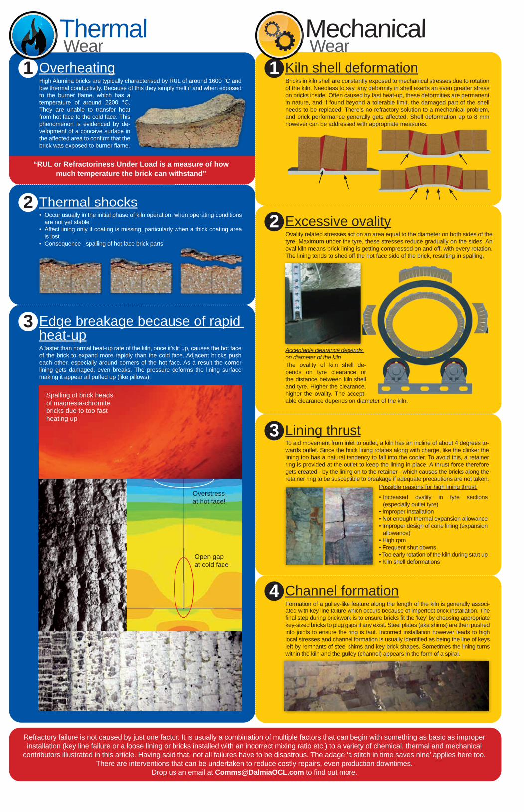
1 Kiln shell deformationBricks in kiln shell are constantly exposed to mechanical stresses due to rotation of the kiln. Needless to say, any deformity in shell exerts an even greater stress on bricks inside. Often caused by fast heat-up, these deformities are permanent in nature, and if found beyond a tolerable limit, the damaged part of the shell needs to be replaced. There’s no refractory solution to a mechanical problem, and brick performance generally gets affected. Shell deformation up to 8 mm however can be addressed with appropriate measures.
2 Excessive ovality
3 Lining thrust
4 Channel formation
Ovality related stresses act on an area equal to the diameter on both sides of the tyre. Maximum under the tyre, these stresses reduce gradually on the sides. An oval kiln means brick lining is getting compressed on and off, with every rotation. The lining tends to shed off the hot face side of the brick, resulting in spalling.
The ovality of kiln shell de-pends on tyre clearance or the distance between kiln shell and tyre. Higher the clearance, higher the ovality. The accept-able clearance depends on diameter of the kiln.
Acceptable clearance depends on diameter of the kiln
To aid movement from inlet to outlet, a kiln has an incline of about 4 degrees to-wards outlet. Since the brick lining rotates along with charge, like the clinker the lining too has a natural tendency to fall into the cooler. To avoid this, a retainer ring is provided at the outlet to keep the lining in place. A thrust force therefore gets created - by the lining on to the retainer - which causes the bricks along the retainer ring to be susceptible to breakage if adequate precautions are not taken.
Formation of a gulley-like feature along the length of the kiln is generally associ-ated with key line failure which occurs because of imperfect brick installation. The final step during brickwork is to ensure bricks fit the ‘key’ by choosing appropriate key-sized bricks to plug gaps if any exist. Steel plates (aka shims) are then pushed into joints to ensure the ring is taut. Incorrect installation however leads to high local stresses and channel formation is usually identified as being the line of keys left by remnants of steel shims and key brick shapes. Sometimes the lining turns within the kiln and the gulley (channel) appears in the form of a spiral.
Possible reasons for high lining thrust:
• Increased ovality in tyre sections (especially outlet tyre)
• Improper installation• Not enough thermal expansion allowance• Improper design of cone lining (expansion
allowance)• High rpm• Frequent shut downs• Too early rotation of the kiln during start up• Kiln shell deformations
Refractory failure is not caused by just one factor. It is usually a combination of multiple factors that can begin with something as basic as improper installation (key line failure or a loose lining or bricks installed with an incorrect mixing ratio etc.) to a variety of chemical, thermal and mechanical
contributors illustrated in this article. Having said that, not all failures have to be disastrous. The adage ‘a stitch in time saves nine’ applies here too. There are interventions that can be undertaken to reduce costly repairs, even production downtimes.
Drop us an email at [email protected] to find out more.
1 OverheatingHigh Alumina bricks are typically characterised by RUL of around 1600 °C and low thermal conductivity. Because of this they simply melt if and when exposed to the burner flame, which has a temperature of around 2200 °C. They are unable to transfer heat from hot face to the cold face. This phenomenon is evidenced by de-velopment of a concave surface in the affected area to confirm that the brick was exposed to burner flame.
“RUL or Refractoriness Under Load is a measure of how much temperature the brick can withstand”
3
2 Thermal shocks
Edge breakage because of rapid heat-up
• Occur usually in the initial phase of kiln operation, when operating conditions are not yet stable
• Affect lining only if coating is missing, particularly when a thick coating area is lost
• Consequence - spalling of hot face brick parts
A faster than normal heat-up rate of the kiln, once it’s lit up, causes the hot face of the brick to expand more rapidly than the cold face. Adjacent bricks push each other, especially around corners of the hot face. As a result the corner lining gets damaged, even breaks. The pressure deforms the lining surface making it appear all puffed up (like pillows).
Overstress at hot face!
Open gap at cold face
Spalling of brick heads of magnesia-chromite bricks due to too fast heating up

coating-repellent, long-lasting refractory lining which can be deployed in a short pe-riod of time. Precasts really have significant advantages:1. Precast shapes generally have a lining
thickness of 70-75 mm to make available extra space inside the feed pipe for great-er material flow and less choking
2. No heat-up is required since the material has already been fired at high tempera-tures and ceramic bonds are already de-veloped to resist abrasion when charge starts to flow through it
3. Due to simplicity of its design, shapes can be assembled quickly making replace-ment real convenient and easy
...continued from first page
Dalmia-OCL has developed precast shape designs based on simplicity of assembly, performance and thermal
conditions, which can be tailored to suit specific requirements.
Email [email protected] today to learn more.
• Tiles, each with thickness of 75 mm, designed of such dimension that 10 of them cover the full circumference
• Precise coupling between two adjacent tiles is achieved using the tongue and groove mechanism
• Tiles are made of high strength alkali resistant low cement castable – Dal-mia-Seven Cast 50NM dried at 450 °C and fired at high temperatures
• The pipe, made up of 1500 mm long modules largely, coupled with each other with a flange and ring design providing weight support; 4 rows of precast tiles can be accommodated in each 1500 mm module, locked into position via a belt of castable & metallic anchors at both ends
• Resulting inner diameter is 850 mm• Differently designed tiles arranged
for shorter pipe modules
Precast tile concept for Feed Pipe designed for a major Indian cement manufacturer
BackgroundKiln dia: 4.35 MArea of concern: 2nd tyre at 34 M
Problem• After deploying brick lining of 54 M, kiln
operations began in mid-June 2018• 1st red spot observed at 34 M 10 days later• 2nd red spot observed at 38 M after anoth-
er 10 days
Observations1. 3 rings of bricks were found missing at 34
M, one at 37.2 M and yet another at 37.8 M.2. It was clear that since the failure was lo-
calised to specific parts of the kiln, it wasn’t because of refractory quality.
3. It was evident that refractory failure in this case was because of shearing stress which had caused breakage around the middle of the bricks - most common type of failure due to ovality of kiln shell. It was therefore decided that ovality of the 2nd tyre area should be measured.
4. It was found that migration at the tyre was up to 30 mm compared to recommended level of 12-15 mm.
Analysis• Migration of 30 mm meant that the hot air
gap at the top between the chair plate and tyre was around 10 mm (against a desir-able level of 4 mm). This situation would accentuate ovality related stresses in an area equal to the diameter on both sides of the tyre i.e. in 30-38 M from outlet.
• Considering the kiln diameter of 4.35 M, a 10 mm air gap implies ovality of 0.7% in-stead of recommended 0.3%, or in this case a maximum tolerable limit of 0.4%
Recommendation• Employ shimming to reduce migration to
around 15 mm• 3 mm shim plates would do the job• Being a typical case of ovality induced re-
fractory failure, unless immediate action is taken, failure may occur again
Wear AnalysisCase Report:
How does one correctly assess kiln shell ovality? It all starts with mea-suring Creep or Migration. Creep is related to Air gap i.e. the difference between inside diameter of a tyre and outside diameter of the kiln shell. Air Gap decreases under hot conditions and is measured through Creep. More Creep means greater ovality, or higher stress therefore on refractory bricks.
Measuring CreepCreep is easily measured by marking both the kiln and tyre with a chalk at the same time. After a few rotations as the kiln goes forward (due to its smaller diameter), the chalkmark on the tyre falls behind. Measuring the distance between the two separat-ed marks and dividing that with the no. of rotations determines Creep (in mm/rev).
Creep and Air Gap are directly propor-tional to each other:
Creep = π x Air GapOr, Air Gap = Creep / π
Air Gap is not totally badA little bit of gap or clearance is re-quired for the kiln shell to expand when heating up so as to not get damaged by the tyre. There’s even a recommended or an ideal clearance measure under hot conditions:
Max clearance = kiln dia (mm) / 1000(For a kiln with diameter of 4800 mm, the max clearance is 4.8 mm)
Recommended Creep = Air Gap x π(Ideal creep for a 4800 mm kiln is 15 mm/rev)
Ovality, Creep & Air Gap
D
Air Gap A = D - d
Inside dia of tyre
Outside dia of kiln
Air Gap = A
d
How do you like The Refractory Beat? Bouquets, brickbats, suggestions & feedback - email us all at [email protected]. We’d love to hear from you.
clinker begins to arrive in the cooler. There have been cases where water in castable when exposed to high temperatures in these areas converts to steam and explodes. Steam escapes, castable lining weakens and begins to fall. It is absolutely imperative that a prop-er and rigorous heat-up schedule is therefore followed for best performance of castables. Pre-fired precast shapes however bypass this scenario altogether.
What makes Precast a better choicePre-fired precast feed pipe linings com-bine high-quality castables with a con-trolled manufacturing process to ensure a