refresh mini, midi & maxi and refresh ultima installation ... · refresh mini, midi & maxi...
TRANSCRIPT
Refresh Mini, Midi & Maxi
and Refresh Ultima
Installation, Operation and Maintenance Manual
Document No. F054
Issue: Final
REFRESH INSTALLATION, OPERATION AND MAINTENANCE MANUAL Overview
Page 2 of 70 Issue: Final
DISCLAIMER Whilst every care is taken in ensuring the information contained herein is accurate, no responsibility implied, or otherwise, is accepted for loss or damage incurred due to this information. It is the responsibility of the reader to ensure the method used is suitable in accordance with relevant health & safety legislation for his particular application and he should satisfy himself by conducting risk assessments and method statements before proceeding with a trial or sample component. The information in this publication may not be regarded as a guarantee for the proprieties of materials or products dealt with or of their processing. Copyright © Britannia Kitchen Ventilation Ltd 2014. All rights reserved. Any redistribution or reproduction of this manual, in part or entirely in any form is strictly prohibited. Revision History
Revision No. Section(s) Revised Revision Date By Whom
Draft All 28th January 2014 AST
Final All 26th March 2014 AST
Britannia Kitchen Ventilation Ltd. 10Highdown Road Sydenham Ind. Estate Leamington Spa Warwickshire CV31 1XT England Phone 01926-463540 Fax 01926-463541 Email sales@kitchen ventilation.co.uk Web www.kitchen-ventilation.co.uk Registered in England 3062962 Registered office Whisby Road, Lincoln, LN6 3QZ
REFRESHINSTALLATION, OPERATION AND MAINTENANCE MANUAL
Overview
Contents
1. Overview 5 1.1 Refresh Mini, Midi & Maxi Units 6 1.2 Refresh Ultima Unit 7
1.2.1 Glossary of Terms 9 1.3 System Overview 10
1.3.1 Functional Description 10
2. Assembly, Installation and Commissioning 17 2.1 Introduction 17
2.1.1 Risk Assessment 17 2.1.2 Access and Offloading 17 2.1.3 Warnings and Cautions 17 2.1.4 Receipt 17 2.1.5 Storage and Preservation 18
2.2 Assembly 18 2.2.1 Preparation for Unpacking 18 2.2.2 Unpacking Procedures 18 2.2.3 Preparation for Assembly 18 2.2.4 Refresh Mini, Midi & Maxi Assembly Procedures 19 2.2.5 Refresh Ultima Assembly Procedures 19
2.3 Installation 20 2.3.1 Preparation for Installation 20 2.3.2 Refresh Mini, Midi & Maxi Assembly Procedures 22 2.3.3 Refresh Ultima Installation Procedures 23
2.4 Commissioning 25 2.4.1 Pre-commissioning Procedures 25 2.4.2 Commissioning Procedures 25 2.4.3 Post Commissioning Procedures 26
3. Operation 27 3.1 Introduction 27
3.1.1 Warnings and Cautions 27 3.1.2 Operation Overview 27
3.2 Operating Procedures 28 3.2.1 Starting-up 28 3.2.2 Increasing the Speed of the Fans 28 3.2.3 Decreasing the Speed of the Fans 29 3.2.4 Muting an Active Alarm 29 3.2.5 Accessing the Information Screens 29 3.2.6 Accessing the “Configuration” Screen from the “Date/Time” Screen 29 3.2.7 Filter Status Screen 29 3.2.8 Shutting-down 30
3.3 Resetting the Filter Operational Hours 31
4. Maintenance 33 4.1 Introduction 33
4.1.1 Warnings and Cautions 33 4.1.2 Equipment, Tools, Consumables and PPE 34
4.2 Preventive Maintenance 35
Issue: Final Page 3 of 70
REFRESH INSTALLATION, OPERATION AND MAINTENANCE MANUAL Overview
4.2.1 Preventive Maintenance Overview 35 4.2.2 Preventive Maintenance Schedule 35 4.2.3 Preventive Maintenance Procedures 37
4.3 Fault Finding 44 4.3.1 Fault Finding Procedures 44
4.4 Corrective Maintenance 46 4.4.1 Maintenance Policy 46 4.4.2 Removal Procedures (Refresh Mini, Midi & Maxi) 46 4.4.3 Removal Procedures (Refresh Ultima) 50 4.4.4 Replacement Procedures (Refresh Mini, Midi & Maxi) 55 4.4.5 Replacement Procedures (Refresh Ultima) 60 4.4.6 Maintenance Checks and Visual Inspections 64
4.5 Spares 68 4.5.1 Spares Tables 68 4.5.2 Ordering Information 69
4.6 GA Diagrams 70 4.6.1 Refresh Mini, Midi & Maxi 70 4.6.2 Refresh Ultima 70
Page 4 of 70 Issue: Final
REFRESHINSTALLATION, OPERATION AND MAINTENANCE MANUAL
Overview
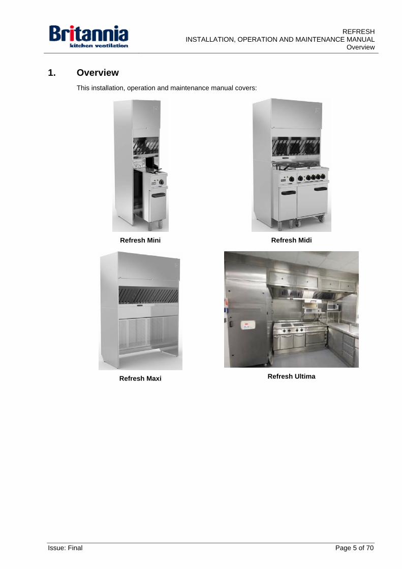
1. Overview
This installation, operation and maintenance manual covers:
Refresh Mini
Refresh Midi
Refresh Maxi
Refresh Ultima
Issue: Final Page 5 of 70
REFRESH INSTALLATION, OPERATION AND MAINTENANCE MANUAL Overview
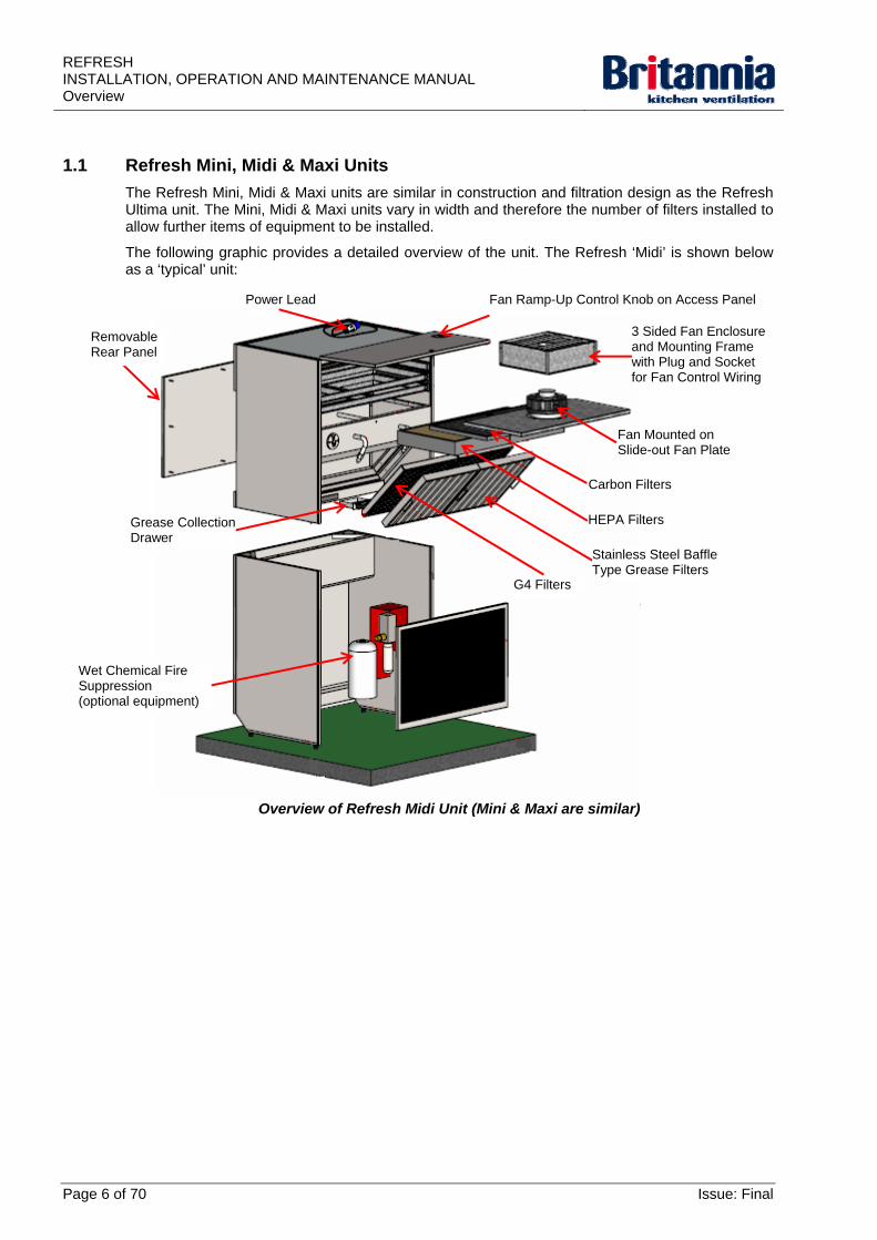
1.1 Refresh Mini, Midi & Maxi Units
The Refresh Mini, Midi & Maxi units are similar in construction and filtration design as the Refresh Ultima unit. The Mini, Midi & Maxi units vary in width and therefore the number of filters installed to allow further items of equipment to be installed.
The following graphic provides a detailed overview of the unit. The Refresh ‘Midi’ is shown below as a ‘typical’ unit:
Overview of Refresh Midi Unit (Mini & Maxi are similar)
Power Lead Fan Ramp-Up Control Knob on Access Panel
3 Sided Fan Enclosure and Mounting Frame with Plug and Socket for Fan Control Wiring
Removable Rear Panel
Fan Mounted on Slide-out Fan Plate
HEPA Filters
Stainless Steel Baffle Type Grease Filters
G4 Filters
Carbon Filters
Grease Collection Drawer
Wet Chemical Fire Suppression (optional equipment)
Page 6 of 70 Issue: Final
REFRESHINSTALLATION, OPERATION AND MAINTENANCE MANUAL
Overview
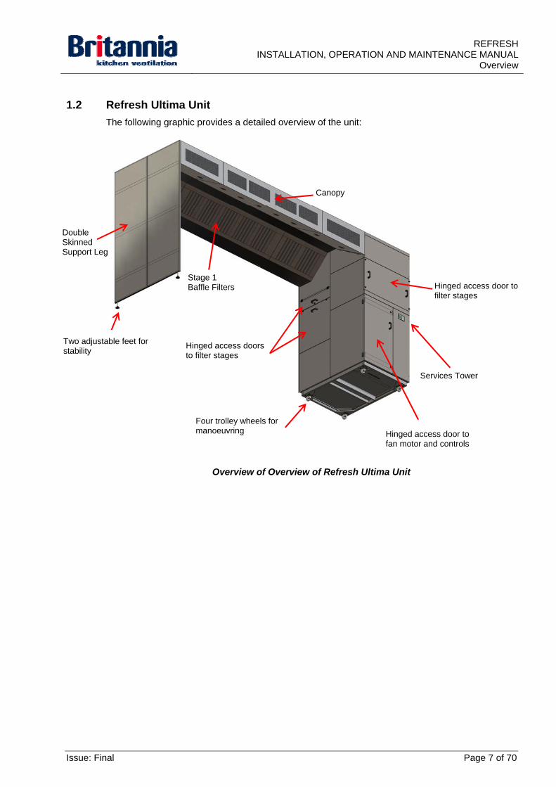
1.2 Refresh Ultima Unit
The following graphic provides a detailed overview of the unit:
Overview of Overview of Refresh Ultima Unit
Canopy
Double Skinned Support Leg
Stage 1 Baffle Filters Hinged access door to
filter stages
Four trolley wheels for manoeuvring
Hinged access doors to filter stages
Two adjustable feet for stability
Services Tower
Hinged access door to fan motor and controls
Issue: Final Page 7 of 70
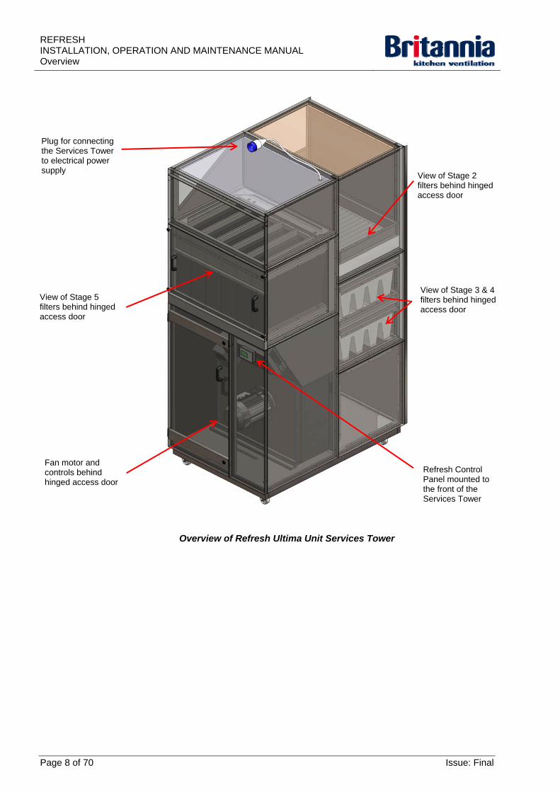
REFRESH INSTALLATION, OPERATION AND MAINTENANCE MANUAL Overview
Plug for connecting the Services Tower to electrical power supply
View of Stage 2 filters behind hinged access door
View of Stage 5 filters behind hinged access door
View of Stage 3 & 4 filters behind hinged access door
Fan motor and controls behind hinged access door
Overview of Refresh Ultima Unit Services Tower
Refresh Control Panel mounted to the front of the Services Tower
Page 8 of 70 Issue: Final
REFRESHINSTALLATION, OPERATION AND MAINTENANCE MANUAL
Overview
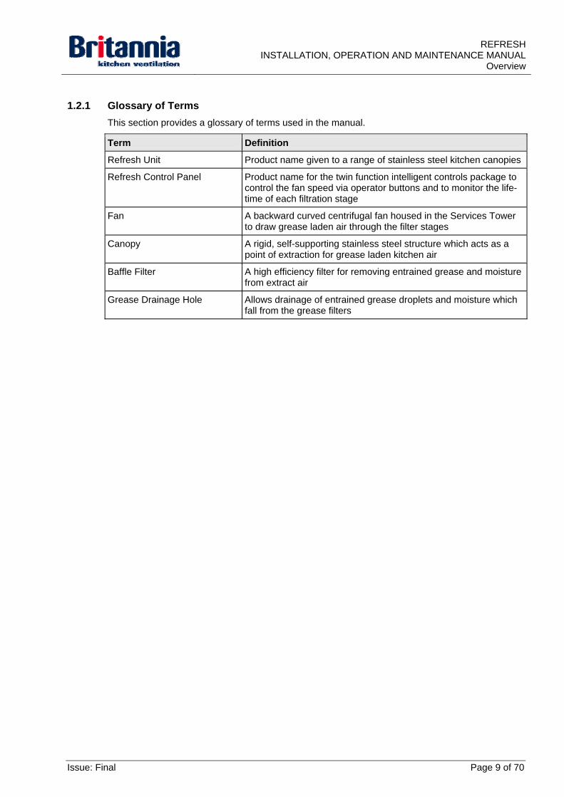
1.2.1 Glossary of Terms
This section provides a glossary of terms used in the manual.
Term Definition
Refresh Unit Product name given to a range of stainless steel kitchen canopies
Refresh Control Panel Product name for the twin function intelligent controls package to control the fan speed via operator buttons and to monitor the life-time of each filtration stage
Fan A backward curved centrifugal fan housed in the Services Tower to draw grease laden air through the filter stages
Canopy A rigid, self-supporting stainless steel structure which acts as a point of extraction for grease laden kitchen air
Baffle Filter A high efficiency filter for removing entrained grease and moisture from extract air
Grease Drainage Hole Allows drainage of entrained grease droplets and moisture which fall from the grease filters
Issue: Final Page 9 of 70
REFRESH INSTALLATION, OPERATION AND MAINTENANCE MANUAL Overview
1.3 System Overview
1.3.1 Functional Description
When cooking, hot, humid and grease laden air is extracted by the unit.
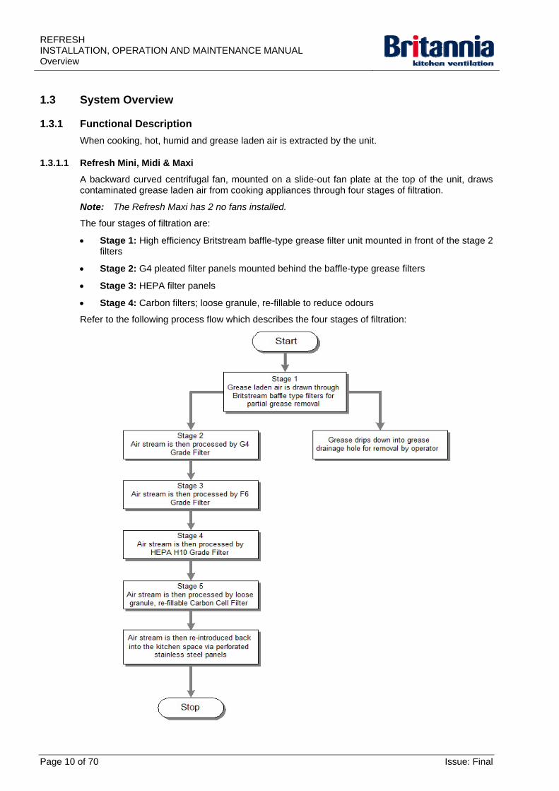
1.3.1.1 Refresh Mini, Midi & Maxi
A backward curved centrifugal fan, mounted on a slide-out fan plate at the top of the unit, draws contaminated grease laden air from cooking appliances through four stages of filtration.
Note: The Refresh Maxi has 2 no fans installed.
The four stages of filtration are:
Stage 1: High efficiency Britstream baffle-type grease filter unit mounted in front of the stage 2 filters
Stage 2: G4 pleated filter panels mounted behind the baffle-type grease filters
Stage 3: HEPA filter panels
Stage 4: Carbon filters; loose granule, re-fillable to reduce odours
Refer to the following process flow which describes the four stages of filtration:
Page 10 of 70 Issue: Final
REFRESHINSTALLATION, OPERATION AND MAINTENANCE MANUAL
Overview
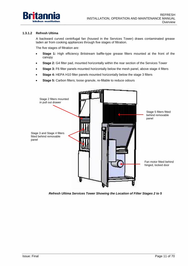
1.3.1.2 Refresh Ultima
A backward curved centrifugal fan (housed in the Services Tower) draws contaminated grease laden air from cooking appliances through five stages of filtration.
The five stages of filtration are:
Stage 1: High efficiency Britstream baffle-type grease filters mounted at the front of the canopy
Stage 2: G4 filter pad, mounted horizontally within the rear section of the Services Tower
Stage 3: F6 filter panels mounted horizontally below the mesh panel, above stage 4 filters
Stage 4: HEPA H10 filter panels mounted horizontally below the stage 3 filters
Stage 5: Carbon filters; loose granule, re-fillable to reduce odours
Refresh Ultima Services Tower Showing the Location of Filter Stages 2 to 5
Stage 2 filters mounted in pull out drawer
Stage 5 filters fitted behind removable panel
Stage 3 and Stage 4 filters fitted behind removable panel
Fan motor fitted behind hinged, locked door
Issue: Final Page 11 of 70
REFRESH INSTALLATION, OPERATION AND MAINTENANCE MANUAL Overview
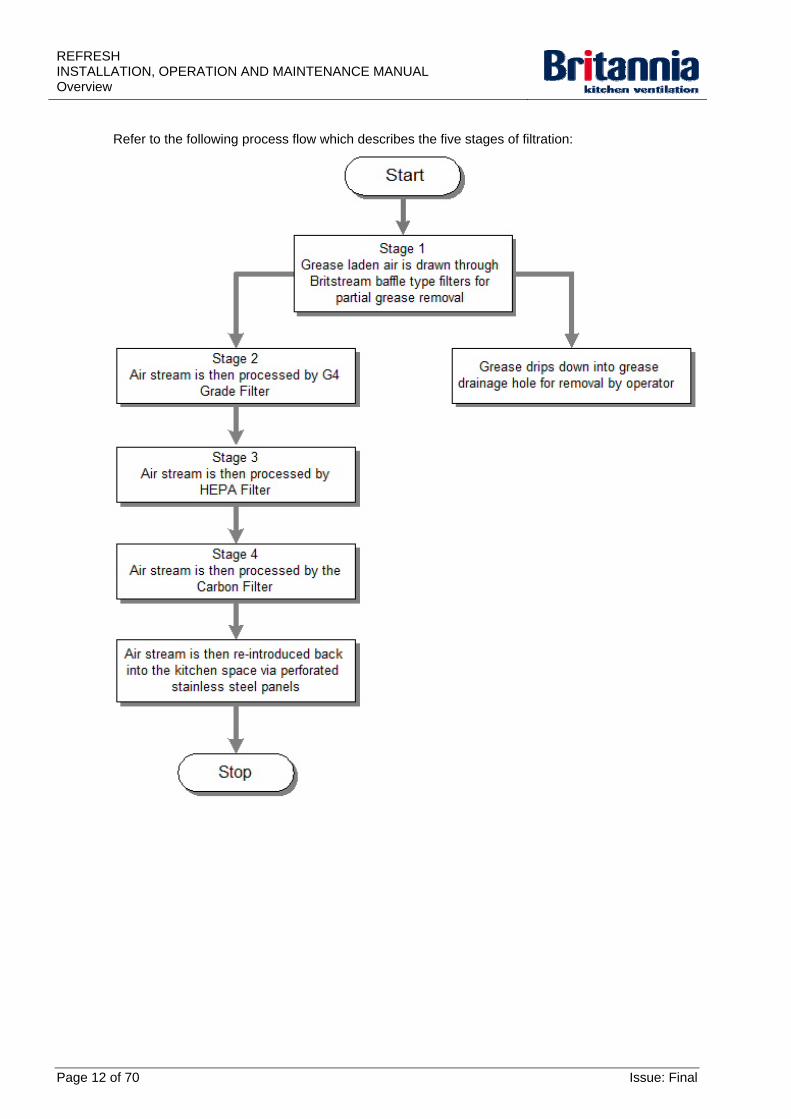
Refer to the following process flow which describes the five stages of filtration:
Page 12 of 70 Issue: Final
REFRESHINSTALLATION, OPERATION AND MAINTENANCE MANUAL
Overview
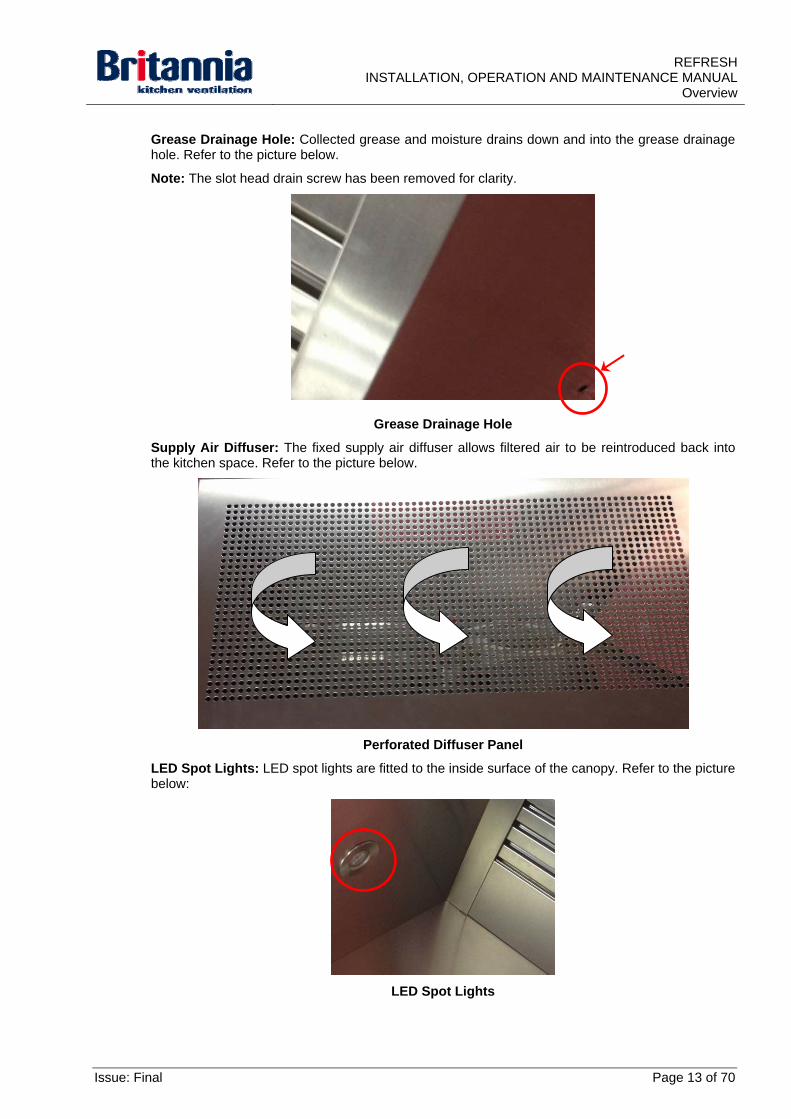
Grease Drainage Hole: Collected grease and moisture drains down and into the grease drainage hole. Refer to the picture below.
Note: The slot head drain screw has been removed for clarity.
Grease Drainage Hole
Supply Air Diffuser: The fixed supply air diffuser allows filtered air to be reintroduced back into the kitchen space. Refer to the picture below.
Perforated Diffuser Panel
LED Spot Lights: LED spot lights are fitted to the inside surface of the canopy. Refer to the picture below:
LED Spot Lights
Issue: Final Page 13 of 70
REFRESH INSTALLATION, OPERATION AND MAINTENANCE MANUAL Overview
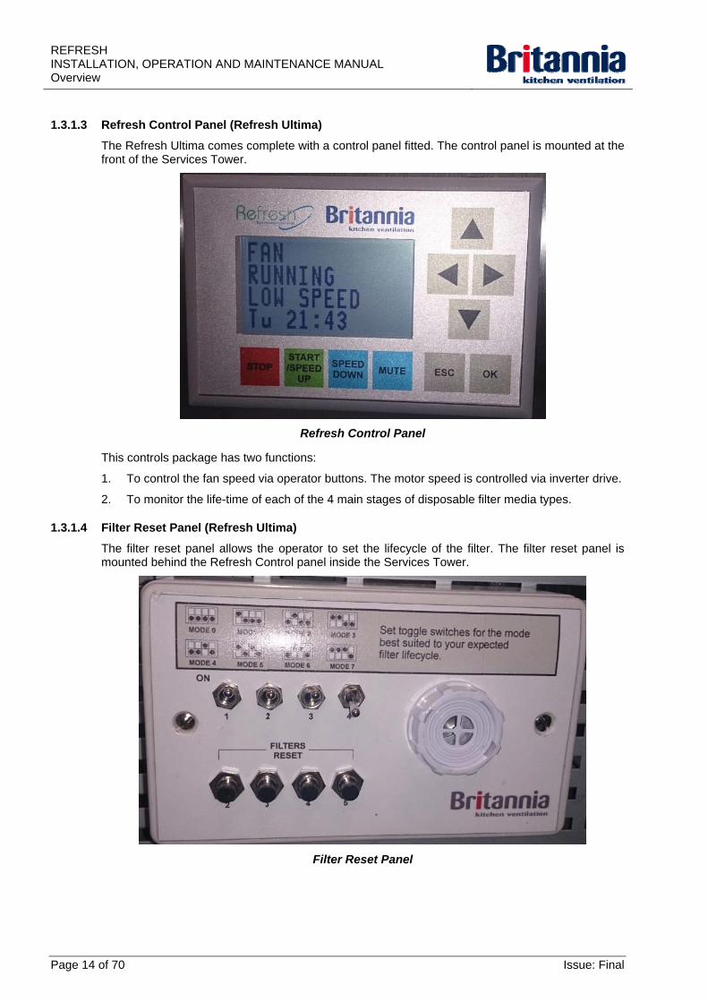
1.3.1.3 Refresh Control Panel (Refresh Ultima)
The Refresh Ultima comes complete with a control panel fitted. The control panel is mounted at the front of the Services Tower.
Refresh Control Panel
This controls package has two functions:
1. To control the fan speed via operator buttons. The motor speed is controlled via inverter drive.
2. To monitor the life-time of each of the 4 main stages of disposable filter media types.
1.3.1.4 Filter Reset Panel (Refresh Ultima)
The filter reset panel allows the operator to set the lifecycle of the filter. The filter reset panel is mounted behind the Refresh Control panel inside the Services Tower.
Filter Reset Panel
Page 14 of 70 Issue: Final
REFRESHINSTALLATION, OPERATION AND MAINTENANCE MANUAL
Overview
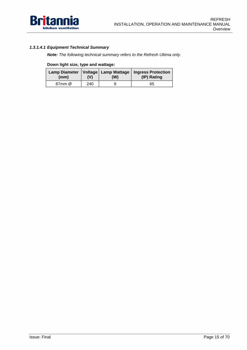
1.3.1.4.1 Equipment Technical Summary
Note: The following technical summary refers to the Refresh Ultima only.
Down light size, type and wattage:
Lamp Diameter (mm)
Voltage (V)
Lamp Wattage (W)
Ingress Protection (IP) Rating
87mm Ø 240 9 65
Issue: Final Page 15 of 70

REFRESH INSTALLATION, OPERATION AND MAINTENANCE MANUAL Overview
This page intentionally blank
Page 16 of 70 Issue: Final
REFRESHINSTALLATION, OPERATION AND MAINTENANCE MANUAL
Assembly, Installation and Commissioning
2. Assembly, Installation and Commissioning
2.1 Introduction
This section refers to all Refresh units.
2.1.1 Risk Assessment
A full risk assessment must be carried out before assembly and installation work commences on site. The risk assessment should identify all Personal Protective Equipment (PPE) requirements. This should be undertaken prior to the installation team arriving. Consideration should also be given to drafting a full method statement for the process.
2.1.2 Access and Offloading
A safe access route must be established into the area in which the Refresh Unit will be installed. This area is to be free from obstruction
A suitable offloading point must be identified before you begin to unload and it should be as close to the installation area as possible
2.1.3 Warnings and Cautions
WARNING: DO NOT INSTALL THIS EQUIPMENT FOR THE VENTILATION OF GAS, OIL OR SOLID
FUELLED EQUIPMENT. RISK TO THE HEALTH OF OPERATIVES CAUSED BY THE ACTUAL COMBUSTION PROCESS WHICH USES UP AVAILABLE OXYGEN FROM THE COOKING
SPACE AND CREATES TOXIC CARBON BASED GAS EMISSIONS. ONLY ELECTRICALLY POWERED EQUIPMENT MUST EVER BE VENTILATED BY THIS TYPE OF SYSTEM
WARNING: COMPETANT PERSONNEL FAMILIAR WITH THE ASSESSMENT OF HAZARDS AND RISKS ASSOCIATED WITH INDUSTRIAL ELECTRICAL AND VENTILATION EQUIPMENT SUCH AS
FANS AND AIR HANDLING UNITS SHOULD INSTALL THE PRODUCT.
WARNING: USE LIFTING EQUIPMENT WHICH HAS A SUITABLE SAFE WORKING LOAD FOR THE
EQUIPMENT BEING LIFTED.
WARNING: ENSURE STEPS, PODIUM STEPS, SCISSOR LIFT OR MOBILE SCAFFOLD TOWER ARE
SECURE AND STABLE BEFORE USE.
WARNING: MAKE SURE THE CANOPY IS FULLY SECURED BEFORE REMOVING THE SUPPORT
STANDS
Caution: Supplied packaging provides protection against scratches and scrapes only
2.1.4 Receipt
Step 1: Check the package is complete to the delivery note and that there are no missing items.
Step 2: Check the package is undamaged.
Step 3: Where items will not be unpacked straight away, check:
Step a) The shrink-wrap is complete and plastic banding is secure.
Step b) There are no edges protruding which can become damaged or cause injury. Where edges are exposed, cover using suitable protection.
Issue: Final Page 17 of 70
REFRESH INSTALLATION, OPERATION AND MAINTENANCE MANUAL Assembly, Installation and Commissioning
2.1.5 Storage and Preservation
2.1.5.1 Storage Caution:
Supplied packaging provides protection against scratches and scrapes only.
Items must not be stored in high traffic areas. No impact protection is provided.
2.1.5.2 Preservation
Items must be stored in dry conditions.
2.2 Assembly
2.2.1 Preparation for Unpacking
Step 1: Ensure you place items to be unpacked as near as possible to the site of installation.
Step 2: Ensure you have sufficient free space to work.
2.2.2 Unpacking Procedures
Step 1: Using a suitable tool, remove the plastic banding around the item
Step 2: Remove all packaging as necessary.
2.2.3 Preparation for Assembly
2.2.3.1 Personnel
Skilled site engineers
Senior site installation engineers (site Foreman).
2.2.3.2 Personal Protective Equipment (PPE)
The need for PPE must be identified once a full risk assessment has been carried out. Refer to Section 2.1.1 Risk Assessment.
Below is a list of PPE that must be worn when assembling BKV equipment:
Safety footwear with steel mid-sole, steel toe caps, padded ankle protection and high grip soles.
High visibility vest
Kevlar gloves
Carpenter gloves
Safety spectacles
Safety goggles.
Tools Required:
Suitable and approved lifting equipment
Adjustable support stands
Spirit level
Suitable hand tools]
Suitable spanner to tighten M10 fixings.
Drawings:
Refer to Section 4.6 GA Diagrams for reference.
Page 18 of 70 Issue: Final
REFRESHINSTALLATION, OPERATION AND MAINTENANCE MANUAL
Assembly, Installation and Commissioning
2.2.4 Refresh Mini, Midi & Maxi Assembly Procedures
The following procedures cover only the Refresh Midi, Maxi and Ultima units as these units require assembly. The refresh Mini is supplied a one-piece unit.
Step 1: Prepare a clear & level area around the proposed installation area in accordance with the drawings with approximately 1 metre clearance all-round the unit for access.
Note: The unit must be installed on a level surface.
Step 2: Install the bottom unit in the proposed installation area.
Step 3: Using the spirit level, make sure the bottom unit is level. Adjust the feet accordingly as necessary and then recheck the level.
Step 4: Using safe and suitable methods lift and then position the first half of the unit on top of the base and lock into position.
Step 5: Assemble the filters and cover panels to the unit as necessary.
2.2.5 Refresh Ultima Assembly Procedures
Services Tower:
Step 1: Prepare a clear & level area around the proposed installation area in accordance with the drawings with approximately 1 metre clearance all-round the unit for access.
Step 2: Safely locate the base of the refresh unit at the correct location and in accordance with the drawings.
WARNING: USE LIFTING EQUIPMENT WHICH HAS A SUITABLE SAFE WORKING LOAD FOR
THE EQUIPMENT BEING LIFTED.
Step 3: Using the lifting equipment], lift the first half of the Services Tower unit on top of the base and lock into position.
Step 4: Slide the second half of the Service Tower unit into position next to the first half ensuring it is flush.
Step 5: Using the M10 fixings, bolt the two sections of the Service Tower together.
Step 6: Using the spanner, tighten the M10 fixings to secure the two sections.
Canopy:
WARNING: USE LIFTING EQUIPMENT WHICH HAS A SUITABLE SAFE WORKING LOAD FOR THE
EQUIPMENT BEING LIFTED.
Step 1: Using the lifting equipment and height adjustable stands, assembly the canopy on a level surface.
Step 2: Place the spirit level on the outer edge of the upper valance to level each section.
Step 3: Assemble the unit from its component parts.
Issue: Final Page 19 of 70
REFRESH INSTALLATION, OPERATION AND MAINTENANCE MANUAL Assembly, Installation and Commissioning
2.3 Installation
2.3.1 Preparation for Installation
WARNING: DO NOT INSTALL THIS EQUIPMENT FOR THE VENTILATION OF GAS, OIL OR SOLID
FUELLED EQUIPMENT. RISK TO THE HEALTH OF OPERATIVES CAUSED BY THE ACTUAL COMBUSTION PROCESS WHICH USES UP AVAILABLE OXYGEN FROM THE COOKING
SPACE AND CREATES TOXIC CARBON BASED GAS EMISSIONS. ONLY ELECTRICALLY POWERED EQUIPMENT MUST EVER BE VENTILATED BY THIS TYPE OF SYSTEM
You must have the following completed documentation before installation of this equipment:
Site installation form
Manufacture and location drawings
Site survey form
Onsite inspection form
Risk assessments
Suitable Method Statements.
2.3.1.1 Personnel
Skilled site engineers
Senior site installation engineers (site Foreman).
2.3.1.2 Personal Protective Equipment (PPE)
The need for PPE must be identified once a full risk assessment has been carried out. Refer to Section 2.1.1 Risk Assessment.
Below is a list of PPE that must be worn when installing BKV equipment:
Site safety hard hat
Safety footwear with steel mid-sole, steel toe caps, padded ankle protection and high grip soles.
High visibility vest
High visibility coat
Kevlar gloves
Carpenter gloves
Safety spectacles
Safety goggles
Vented dust masks
Ear Defenders.
Page 20 of 70 Issue: Final
REFRESHINSTALLATION, OPERATION AND MAINTENANCE MANUAL
Assembly, Installation and Commissioning
2.3.1.3 Tools, Equipment, Consumables and Fixings Required
Tools:
Spirit level
Suitable spanner to tighten M6 fixings
Suitable tool to tighten the canopy to the kitchen wall (where necessary).
Equipment: Mobile tower scaffold
Podium steps
Steps (when required)
Scissor Lift (when required)
Suitable and approved lifting equipment
Adjustable support stands
Battery Powered Impact Drill
Battery Powered Hammer drills
Battery Powered Hand drills
Battery Powered Grinderette.
Consumables:
Unistrut
Fixings box containing an assortment of mechanical fixings and accessories
Silicone sealant.
Fixings:
M6 fixings
M10 fixings
Suitable screws, plugs or anchors as necessary (to fix the canopy against the wall).
2.3.1.4 General Installation Notes
To avoid the risk of accidents and damage to the kitchen Refresh Unit the following should be adhered to:
You must install the Refresh Unit in accordance with these instructions
Any installation work must be carried out by competent personnel
In all cases, a minimum of two competent personnel are required
Installation personnel should be fully trained in all relevant tools and equipment required to successfully install the Refresh Unit
A safe method of access to the fixing points must be gained by use of previously identified suitable access equipment
It is suggested that at least a small air change rate in the order of 10 to 15 air changes per hour be incorporated if possible. This will provide a small amount of background ventilation, create a negative pressure and help retain cooking odours within the kitchen space
Before installation, check the building structure to which the Refresh Unit is to be fitted for:
o Electric cables
o Gas pipes
o Water pipes.
Issue: Final Page 21 of 70
REFRESH INSTALLATION, OPERATION AND MAINTENANCE MANUAL Assembly, Installation and Commissioning
All equipment installed below the Refresh Unit must either be:
o Fully removable, or
o Mounted or positioned in such a way as to allow regular access to the filter grease drawer
o Mounted or positioned in such a way as to allow regular access to the door on the Inside face of the tower.
Refer to Section 4.6 GA Diagrams for reference.
This guide contains WARNINGS and Cautions regarding safety procedures that must be followed.
2.3.2 Refresh Mini, Midi & Maxi Assembly Procedures
The following procedures cover only the Refresh Midi, Maxi and Ultima units as these units require assembly. The refresh Mini is supplied a one-piece unit.
Step 1: Prepare a clear & level area around the proposed installation area in accordance with the drawings with approximately 1 metre clearance all-round the unit for access.
Note: The unit must be installed on a level surface.
Step 2: Install the bottom unit in the proposed installation area.
Step 3: Using the spirit level, make sure the bottom unit is level. Adjust the feet accordingly as necessary and then recheck the level.
Step 4: Using safe and suitable methods lift and then position the first half of the unit on top of the base and lock into position.
Step 5: Assemble the filters and cover panels to the unit as necessary.
Step 6: To secure the unit to the building fabric (by others), at the top rear of the unit use the 2 looped end retaining wires.
2.3.2.1 Installing the Unit
Please note the following step guidelines must be taken into consideration during the installation of BKV products.
WARNING: COMPETENT PERSONNEL FAMILIAR WITH THE ASSESSMENT OF HAZARDS AND RISKS ASSOCIATED WITH INDUSTRIAL ELECTRICAL AND VENTILATION EQUIPMENT SUCH AS
FANS AND AIR HANDLING UNITS SHOULD INSTALL THIS EQUIPMENT.
Step 1: Check the unit is correctly assembled. Refer to Section 2.2.4 Refresh Mini, Midi & Maxi Assembly Procedures.
Step 2: Where it is necessary to fix the unit against a wall:
Step a) Using the battery powered equipment, Unistrut and fixings from the fixings box, mount the unit against the wall.
Step b) Using the spirit level, make sure the unit is still level.
Step c) Using screws, plugs or anchors, fix the unit to the wall. Using a suitable tool, tighten the fixings until the unit is fully secure.
Step 3: Connect the main power lead to the incoming power supply.
Step 4: Install the required filters, blanks and panels into correct openings and positions.
Step 5: Complete the “On site final inspection” checklist.
Step 6: The customer site contact or main contractor must inspect the completed installation and sign the “Site installation form”. All comments, provisos or alternative instructions given must be noted on this form. Leave a copy with signee for their records.
Page 22 of 70 Issue: Final
REFRESHINSTALLATION, OPERATION AND MAINTENANCE MANUAL
Assembly, Installation and Commissioning
2.3.3 Refresh Ultima Installation Procedures
2.3.3.1 Installing the Canopy
Please note the following step guidelines must be taken into consideration during the installation of BKV products.
WARNING: COMPETENT PERSONNEL FAMILIAR WITH THE ASSESSMENT OF HAZARDS AND RISKS ASSOCIATED WITH INDUSTRIAL ELECTRICAL AND VENTILATION EQUIPMENT SUCH AS
FANS AND AIR HANDLING UNITS SHOULD INSTALL THIS EQUIPMENT.
WARNING: ENSURE STEPS, PODIUM STEPS, SCISSOR LIFT OR MOBILE SCAFFOLD TOWER ARE
SECURE AND STABLE BEFORE USE.
Step 1: Check the Services Tower and the canopy are correctly assembled. Refer to Section 2.2.4 Refresh Mini, Midi & Maxi Assembly Procedures.
Step 2: Position the steps, podium steps, scissor lift or mobile scaffold tower as necessary to aid installation.
Step 3: Safely secure the canopy to the lifting equipment.
WARNING: USE LIFTING EQUIPMENT WHICH HAS A SUITABLE SAFE WORKING LOAD FOR
THE EQUIPMENT BEING LIFTED.
Step 4: Using the lifting equipment, raise the canopy to the correct height then using the adjustable support stands safely support the canopy.
Step 5: Using the location holes on the Services Tower and the canopy, locate the two items together and then use the M6 fixings to secure. Using the spanner tighten the M6 fixings until fully secure.
Step 6: Using the holes in the canopy and the double-skinned support leg, locate the two items together and then use the M6 fixings to secure. Using the spanner tighten the M6 fixings until fully secure.
Step 7: Using a spirit level, check the lateral position of unit.
Step 8: Where applicable, using the battery powered equipment, Unistrut and fixings from the fixings box, mount the canopy to the wall.
Step 9: Using screws, plugs or anchors, fix the canopy to the wall. Using a suitable tool, tighten until the canopy is fully secure.
WARNING: MAKE SURE THE CANOPY IS FULLY SECURED BEFORE REMOVING THE
SUPPORT STANDS.
Step 10: Slowly lower down the support stands approximately 50mm and make sure the canopy is fully secured to the Services Tower and double-skinned support leg and also to the wall (as necessary). Further tighten the all fixings as necessary.
Step 11: Connect the main power lead to the incoming power supply.
Step 12: Peel back the poly coat to expose canopy joints. Do not remove protective film from the canopy. This will be done by others.
Step 13: Using the silicone sealant, seal:
Step a) Joins in the unit
Step b) Joints between walls and ceilings (where necessary).
Step 14: Install the required filters, blanks and panels into correct openings and positions.
Step 15: Complete the “On site final inspection” checklist.
Issue: Final Page 23 of 70
REFRESH INSTALLATION, OPERATION AND MAINTENANCE MANUAL Assembly, Installation and Commissioning
Step 16: The customer site contact or main contractor must inspect the completed installation and sign the “Site installation form”. All comments, provisos or alternative instructions given must be noted on this form. Leave a copy with signee for their records.
Page 24 of 70 Issue: Final
REFRESHINSTALLATION, OPERATION AND MAINTENANCE MANUAL
Assembly, Installation and Commissioning
2.4 Commissioning
2.4.1 Pre-commissioning Procedures
2.4.1.1 PPE
Suitable protective clothing.
2.4.1.2 Refresh Control Panel
Once all of the wiring has been completed and tested, the system is ready to be commissioned. Refer to Section 2.4.2 below.
2.4.2 Commissioning Procedures
2.4.2.1 Setting up the Filter Lifetime Monitoring
Note: The following procedures apply to the Refresh Ultima only.
Filter Life Expectancies
This will vary depending upon the establishment. For this reason the life expectancies can be reprogrammed to suit. However, the pre-set default times will be as per the maintenance table for “Medium category establishments” unless Britannia Kitchen Ventilation has been instructed to provide a different setup (in writing and prior to delivery). Refer to Section 4.2 Preventive Maintenance.
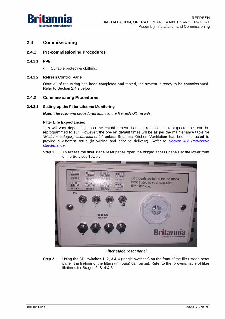
Step 1: To access the filter stage reset panel, open the hinged access panels at the lower front of the Services Tower.
Filter stage reset panel
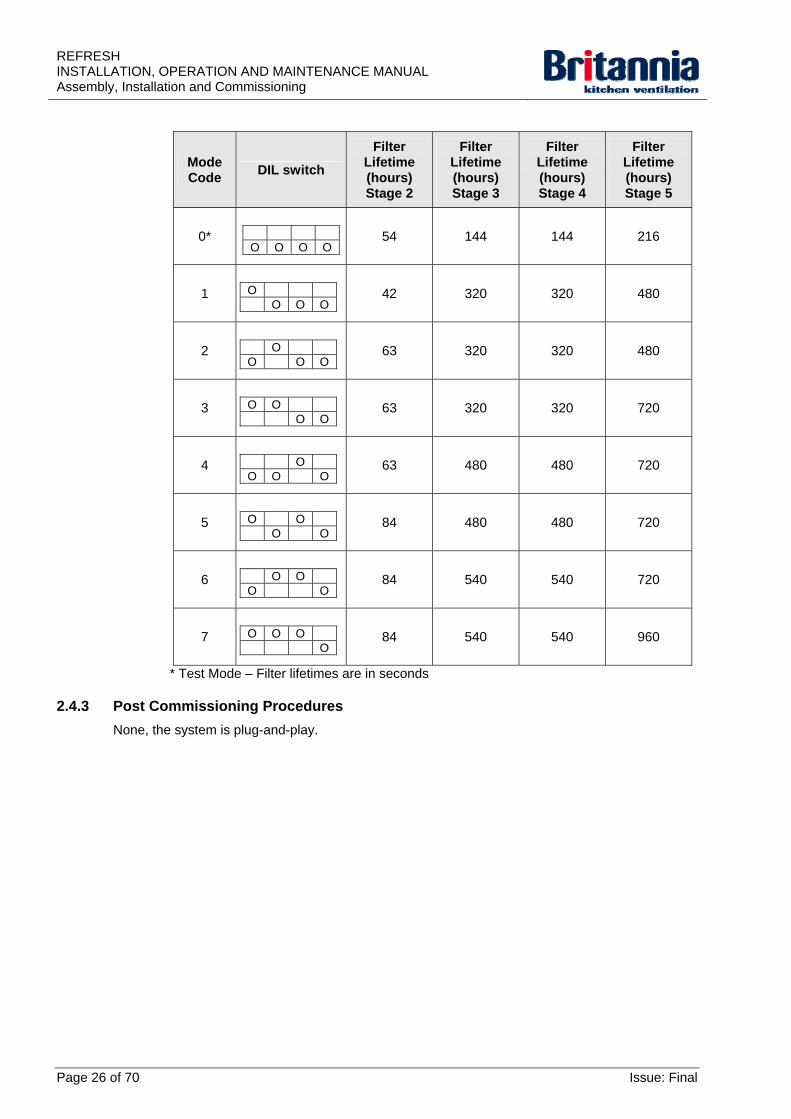
Step 2: Using the DIL switches 1, 2, 3 & 4 (toggle switches) on the front of the filter stage reset panel; the lifetime of the filters (in hours) can be set. Refer to the following table of filter lifetimes for Stages 2, 3, 4 & 5:
Issue: Final Page 25 of 70
REFRESH INSTALLATION, OPERATION AND MAINTENANCE MANUAL Assembly, Installation and Commissioning
Mode Code
DIL switch
Filter Lifetime (hours) Stage 2
Filter Lifetime (hours) Stage 3
Filter Lifetime (hours) Stage 4
Filter Lifetime (hours) Stage 5
0*
O O O O
54 144 144 216
1
O O O O
42 320 320 480
2
O O O O
63 320 320 480
3
O O O O
63 320 320 720
4
O O O O
63 480 480 720
5
O O O O
84 480 480 720
6
O O O O
84 540 540 720
7
O O O O
84 540 540 960
* Test Mode – Filter lifetimes are in seconds
2.4.3 Post Commissioning Procedures
None, the system is plug-and-play.
Page 26 of 70 Issue: Final
REFRESHINSTALLATION, OPERATION AND MAINTENANCE MANUAL
Operation
3. Operation
3.1 Introduction
This section provides operating instructions for the Refresh Control Panel. The Refresh Control Panel is installed in the Refresh Ultima only.
Warnings and Cautions use the following conventions:
WARNING - danger of death or to the health of personnel
Caution - danger of damage to equipment.
3.1.1 Warnings and Cautions Caution:
It is recommend that the end user should carry-out detailed in-house risk assessments for all aspects of operating Refresh Units.
3.1.2 Operation Overview
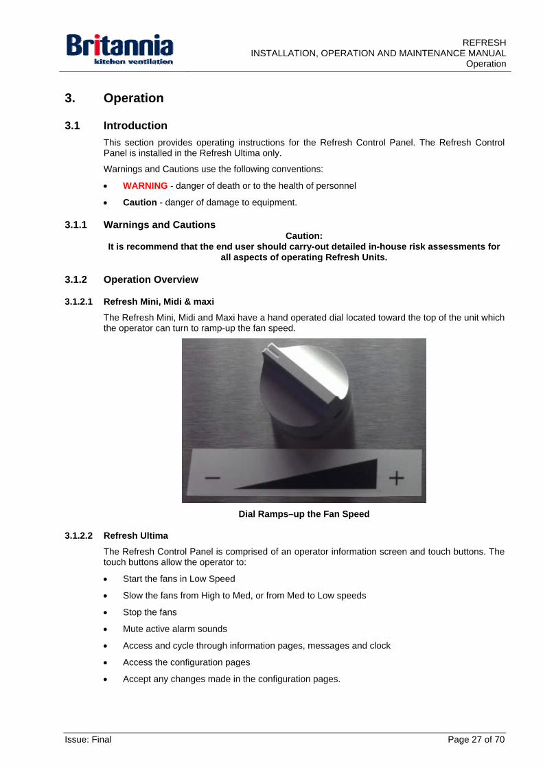
3.1.2.1 Refresh Mini, Midi & maxi
The Refresh Mini, Midi and Maxi have a hand operated dial located toward the top of the unit which the operator can turn to ramp-up the fan speed.
Dial Ramps–up the Fan Speed
3.1.2.2 Refresh Ultima
The Refresh Control Panel is comprised of an operator information screen and touch buttons. The touch buttons allow the operator to:
Start the fans in Low Speed
Slow the fans from High to Med, or from Med to Low speeds
Stop the fans
Mute active alarm sounds
Access and cycle through information pages, messages and clock
Access the configuration pages
Accept any changes made in the configuration pages.
Issue: Final Page 27 of 70
REFRESH INSTALLATION, OPERATION AND MAINTENANCE MANUAL Operation
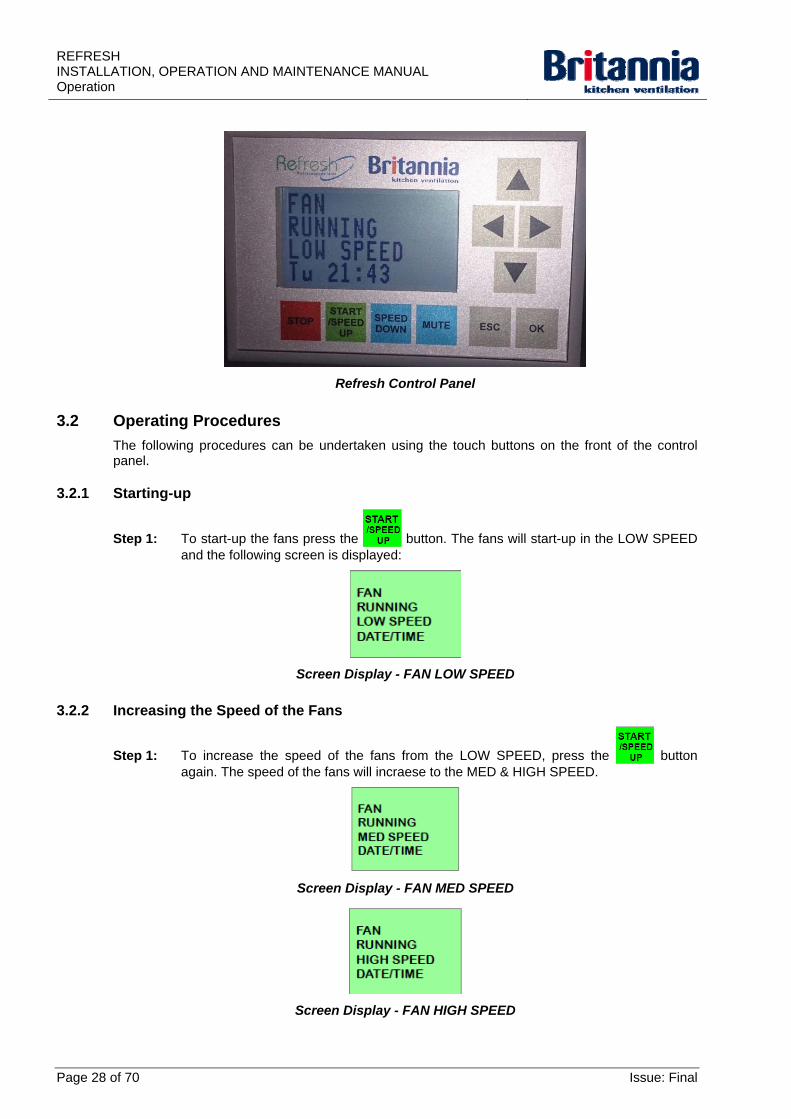
Refresh Control Panel
3.2 Operating Procedures
The following procedures can be undertaken using the touch buttons on the front of the control panel.
3.2.1 Starting-up
Step 1: To start-up the fans press the button. The fans will start-up in the LOW SPEED and the following screen is displayed:
Screen Display - FAN LOW SPEED
3.2.2 Increasing the Speed of the Fans
Step 1: To increase the speed of the fans from the LOW SPEED, press the button again. The speed of the fans will incraese to the MED & HIGH SPEED.
Screen Display - FAN MED SPEED
Screen Display - FAN HIGH SPEED
Page 28 of 70 Issue: Final
REFRESHINSTALLATION, OPERATION AND MAINTENANCE MANUAL
Operation
3.2.3 Decreasing the Speed of the Fans
Step 1: To decrease the speed of the fans from the MED & HIGH SPEED, press the button again. The speed of the fans will decraese from HIGH to MED SPEED or MED to LOW SPEED.
3.2.4 Muting an Active Alarm
Step 1: To mute an active alarm sound, press the button.
3.2.5 Accessing the Information Screens
The operator can access the following messages:
System status
Fan speed
Filter status.
Note: Only active messages are shown.
Step 1: To access the information screens, press the arrow buttons.
Step 2: To cycle through messages and clock screens, press the arrow buttons.
3.2.6 Accessing the “Configuration” Screen from the “Date/Time” Screen
Step 1: To access the “Configuration” screen from the “Date/Time” screen, press the button. The operator can make changes from the “Configuration” screen as necessary.
Step 2: To save changes made from the “Configuration” screen, press the button.
Step 3: To cancel changes made from the “Configuration” screen, press the button.
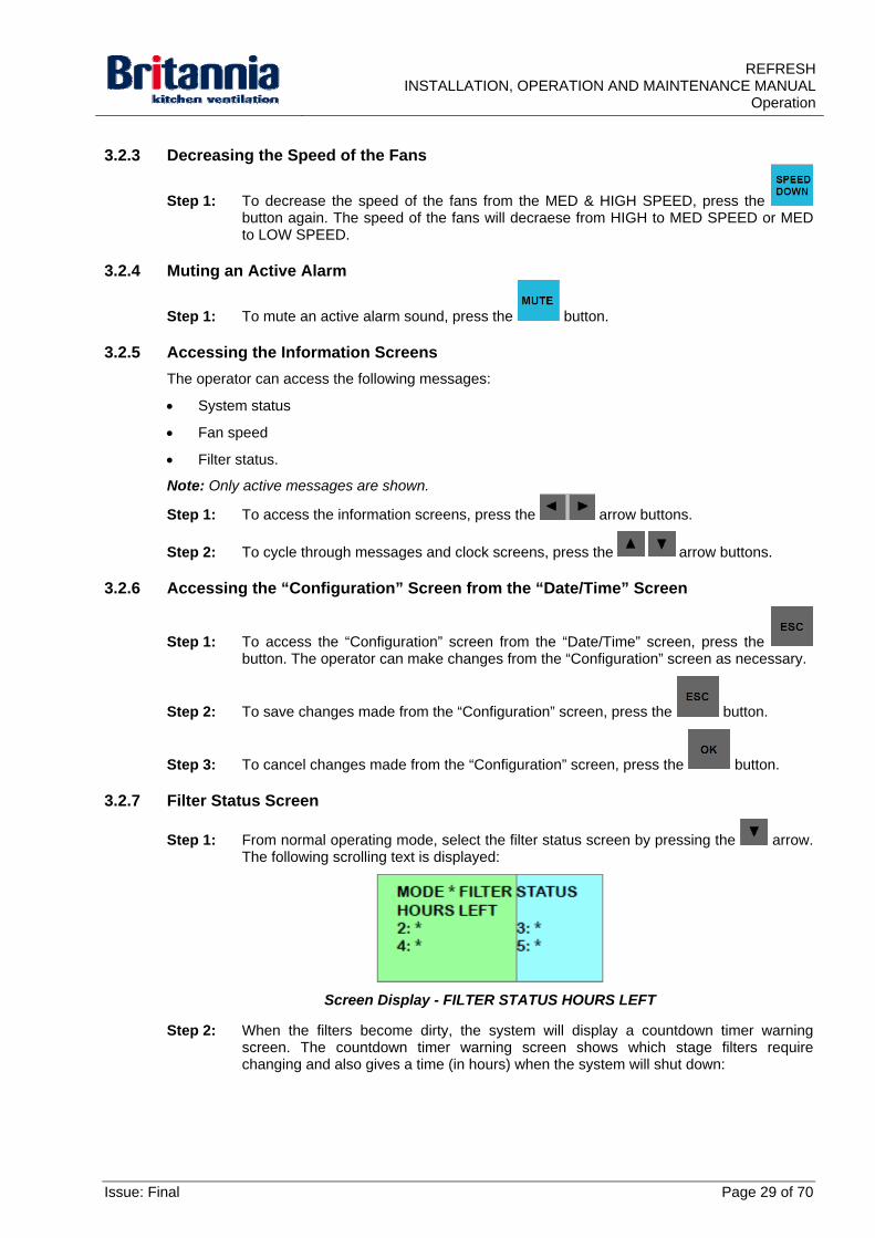
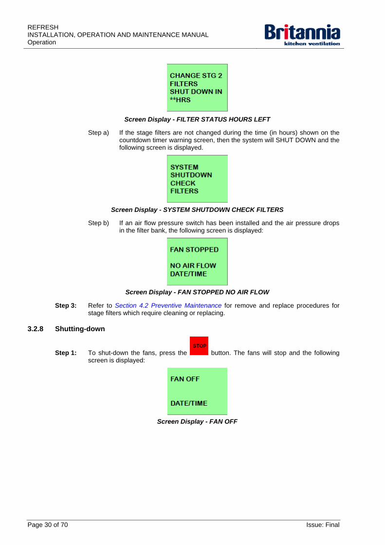
3.2.7 Filter Status Screen
Step 1: From normal operating mode, select the filter status screen by pressing the arrow. The following scrolling text is displayed:
Screen Display - FILTER STATUS HOURS LEFT
Step 2: When the filters become dirty, the system will display a countdown timer warning screen. The countdown timer warning screen shows which stage filters require changing and also gives a time (in hours) when the system will shut down:
Issue: Final Page 29 of 70
REFRESH INSTALLATION, OPERATION AND MAINTENANCE MANUAL Operation
Screen Display - FILTER STATUS HOURS LEFT
Step a) If the stage filters are not changed during the time (in hours) shown on the countdown timer warning screen, then the system will SHUT DOWN and the following screen is displayed.
Screen Display - SYSTEM SHUTDOWN CHECK FILTERS
Step b) If an air flow pressure switch has been installed and the air pressure drops in the filter bank, the following screen is displayed:
Screen Display - FAN STOPPED NO AIR FLOW
Step 3: Refer to Section 4.2 Preventive Maintenance for remove and replace procedures for stage filters which require cleaning or replacing.
3.2.8 Shutting-down
Step 1: To shut-down the fans, press the button. The fans will stop and the following screen is displayed:
Screen Display - FAN OFF
Page 30 of 70 Issue: Final
REFRESHINSTALLATION, OPERATION AND MAINTENANCE MANUAL
Operation
3.3 Resetting the Filter Operational Hours
The following procedures show how to stop the fans, remove and replace the stage filters which have become dirty and reset the filter operational hours:
Step 1: Shut-down the fans by pressing the button. The fans will stop.
Step 2: Remove the stage filters which are displayed on the screen (CHANGE STAGE 2 FILTERS is given in the above example). Refer to the following remove procedures as necessary:
Removing Stage 2 Filters
Removing Stage 3 Filters
Removing Stage 4 Filters
Removing Stage 5 Carbon Cells
Step 3: Replace the stage filters. Refer to the following replace procedures as necessary:
Replacing Stage 2 Filters
Replacing Stage 3 Filters
Replacing Stage 4 Filters
Replacing Stage 5 Carbon Cells
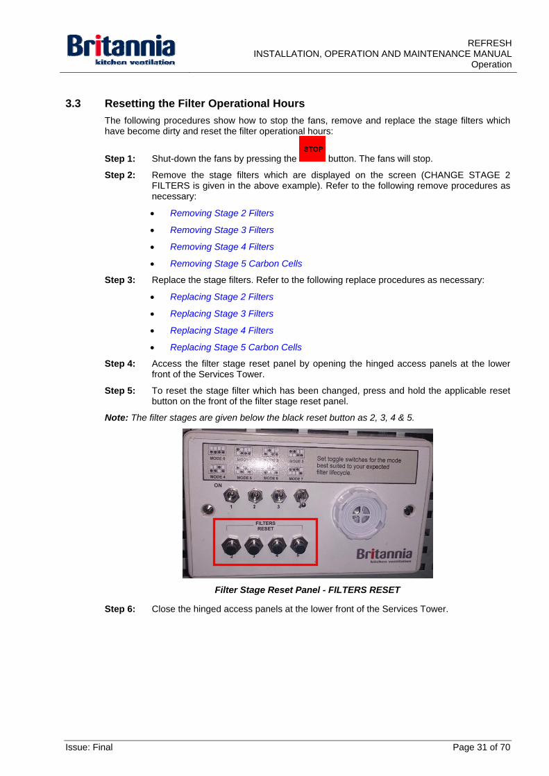
Step 4: Access the filter stage reset panel by opening the hinged access panels at the lower front of the Services Tower.
Step 5: To reset the stage filter which has been changed, press and hold the applicable reset button on the front of the filter stage reset panel.
Note: The filter stages are given below the black reset button as 2, 3, 4 & 5.
Filter Stage Reset Panel - FILTERS RESET
Step 6: Close the hinged access panels at the lower front of the Services Tower.
Issue: Final Page 31 of 70
REFRESH INSTALLATION, OPERATION AND MAINTENANCE MANUAL Operation
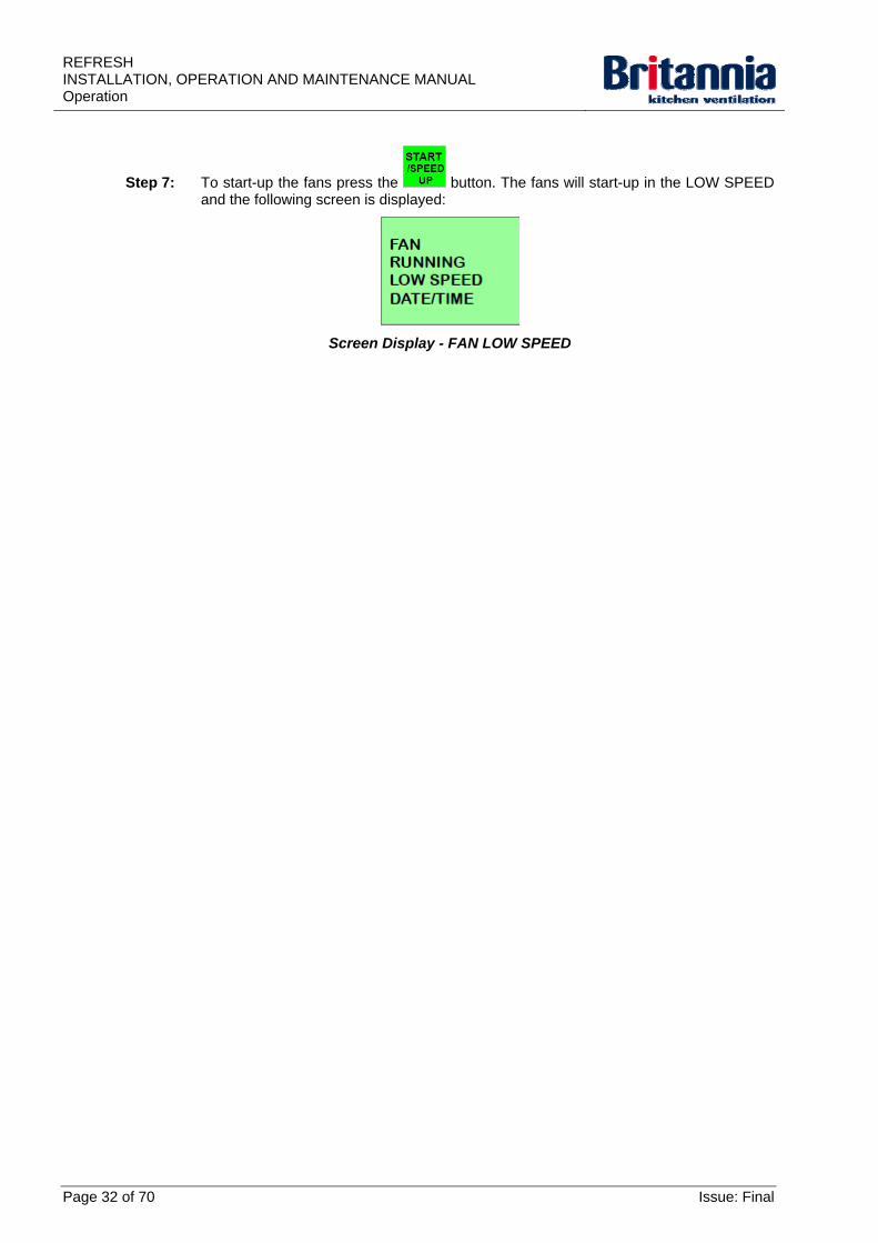
Step 7: To start-up the fans press the button. The fans will start-up in the LOW SPEED and the following screen is displayed:
Screen Display - FAN LOW SPEED
Page 32 of 70 Issue: Final
REFRESHINSTALLATION, OPERATION AND MAINTENANCE MANUAL
Maintenance
4. Maintenance
4.1 Introduction
Warnings and Cautions use the following conventions:
WARNING - danger of death or to the health of personnel
Caution - danger of damage to equipment.
4.1.1 Warnings and Cautions
WARNING: IF ANY INFORMATION PROVIDED IN THIS OPERATION AND MAINTENANCE MANUAL IS
NOT CLEAR YOU MUST STOP WORK AND CONTACT BRITANNIA KITCHEN VENTILATION.
WARNING: CLEANING AND MAINTENANCE MUST ONLY BE UNDERTAKEN BY COMPETENT PERSONNEL ONCE ALL EQUIPMENT SUCH AS OVENS, GRILLS AND FYERS ARE
SWITCHED OFF AND ALL SURFACES HAVE SUFFICIENTLY COOLED.
WARNING: FILTERS STAGES SHOULD ONLY BE REPLACED BY TRAINED OPERATIVES OR
BRITANNIA KITCHEN VENTILATION SERVICE TEAM, CONTACT BRITANNIA FOR FURTHER DETAILS.
WARNING: YOU SHOULD WEAR SUITABLE GRIPPING, CUT-RESISTANT WORK-GLOVES WHEN
HANDLING AND CLEANING THE REFRESH UNIT.
WARNING: ACCESS TO FILTERS FOR REMOVAL & REPLACEMENT WILL OFTEN MEAN REACHING
ABOVE HEAD HEIGHT. YOU MUST USE SUITABLE ACCESS EQUIPMENT AND SAFE WORKING PROCEDURES.
WARNING: YOU MUST WEAR SUITABLE RUBBER GLOVES WHEN CLEANING WITH ANY ACID
SOLUTIONS. SPECIAL PRECAUTIONS ARE NECESSARY WITH OXALIC ACID. SOLVENTS SHOULD NOT BE USED IN ENCLOSED PLACES.
WARNING: USE SUITABLE AND APPROVED EQUIPMENT WHEN WORKING AT HEIGHT.
WARNING: IF THE INTERNAL SURFACES OF THE SYSTEM ITSELF ARE NOT REGULARLY AND THOROUGHLY CLEANED, THEN THE RESIDUAL ODOURS OF DEPOSITED GREASE
THROUGHOUT THE SYSTEM WILL BE DETECTABLE IN THE RETURN SUPPLY AIR FLOW RE-ENTERING THE ROOM SPACE.
Caution: If primary filtration is not regularly cleaned & maintained, then hygiene and fire risks are
created down-stream.
Caution: The particulate filters are positioned to protect the fan and carbon filters. If they are not
monitored and replaced regularly, then the life-span of the carbon filters will be drastically reduced and the fan will become grease loaded and could start to run out of balance
causing long-term damage to bearings and impeller.
Issue: Final Page 33 of 70
REFRESH INSTALLATION, OPERATION AND MAINTENANCE MANUAL Maintenance
4.1.2 Equipment, Tools, Consumables and PPE
4.1.2.1 Equipment
Commercial Dishwasher
Suitable and approved access equipment
Bucket.
4.1.2.2 Tools
Allen key (6 mm)
Small flat bladed screwdriver.
4.1.2.3 Consumables
Lint free cleaning cloth
Clean dry soft cloth
Mild detergent (Fairy Liquid)
Commercial heavy duty detergent
100% isopropyl alcohol
Clean warm water
Suitable Acetone and Alcohol
Suitable Abrasive free stainless steel cleaning cream
Oxalic Acid
Suitable swab
Suitable impregnated nylon pads
Suitable scurf’s dressed with iron free abrasives
Suitable container to drain grease into.
4.1.2.4 PPE
Kevlar gloves (for general equipment handling and cleaning)
Rubber gloves (when cleaning using acid, alcohol and acetone).
Page 34 of 70 Issue: Final
REFRESHINSTALLATION, OPERATION AND MAINTENANCE MANUAL
Maintenance
4.2 Preventive Maintenance
4.2.1 Preventive Maintenance Overview
Britannia canopies and their components are designed to be easy to clean providing that cleaning intervals are not left too long. When too long a period is left between cleans, grease will become baked-on and require special attention. An enhanced aesthetic appearance will be achieved if the cleaned surface is finally wiped dry.
No grease filtration is 100% efficient and therefore there will always be a certain amount of grease carried through the filters and deposited on the internal surfaces of the filter housings, plenums and ductwork.
The amount of grease carried through any filtration system will depend very much on the type of cooking and ingredients used. If left unattended, this layer of grease on the non-visible surfaces of the Refresh Unit creates both hygiene and fire risks.
Regular inspections are recommended and should cover both the internal and external Refresh Unit surfaces, especially non-visible ones.
We strongly recommend that the end user should carry-out detailed in-house risk assessments for all aspects of maintaining Refresh Units.
When handling any components of a canopy, it is imperative that operatives wear proper, gripping, cut-resistant work-gloves for protection against metal edges, as well as the detergents and cleaning agents used. No matter how well finished a fabrication may be, it is easy to cut soft water-soaked skin during the cleaning process.
Canopies and their components by their very nature will have a coating of grease and therefore will be slippery and difficult to handle. Suitable gloves can be obtained easily through most suppliers of personal protective equipment. Access to filters for removal & replacement will often mean reaching above head height and as such, suitable access equipment and or safe working procedures may be required.
The life expectancy and efficiency of each component part of the Refresh Unit, relies upon careful maintenance of the entire system. If the maintenance of one component is neglected, then it can have a serious knock-on effect to other parts of the system rendering them useless or creating permanent damage.
In essence, good maintenance costs time and money and must be budgeted for. However, a lack of maintenance will inevitably cost many times as much in the longer term; due to repair bills, replacement parts, operator discomfort and occupational health risks.
A properly controlled and planned maintenance schedule must be implemented immediately in order that maximum system efficiency is achieved at all times so minimising occupational health risks to operatives. This will also reduce the likelihood of nuisance odours and fumes occurring.
4.2.1.1 Personnel
Skilled site engineers
Senior site installation engineers (site Foreman).
4.2.2 Preventive Maintenance Schedule
The frequency of preventive maintenance will depend upon:
The type of establishment
The level of output
The type of cooking
The regularity and duration of cooking.
Issue: Final Page 35 of 70
REFRESH INSTALLATION, OPERATION AND MAINTENANCE MANUAL Maintenance
Level of output and establishment types have been categorised as follows:
Light: pub & bar food, small cafes, coffee shops and tea shops
Light/medium: schools, hospitals, care homes, office and workplace kitchens
Medium: Italian, French, hotel, pub, pizza and supermarket restaurants
Medium/high: small, low output fast food restaurants, steak houses, kebab and chip shops
High: large, high output fast food, Mexican, Oriental and Asian restaurants
Very high: food production factories.
Deciding upon when cleaning should take place and how often, is mostly subjective and responsibility is ultimately with the manager of the facility.
Regular inspections are recommended and should cover both the internal and external canopy surfaces. As a very rough guide to cleaning schedules please refer to the following tables:
Cleaning and maintenance of kitchen canopies and associated items should only be carried out by suitably skilled and trained operatives, in the absence of such operatives a specialist sub-contractor should be engaged and retained for the purpose. If in-house staff members are to be used, they will require training in monitoring, testing and handling of the various components.
Failure to properly maintain the Refresh unit and its components will invalidate any warranties or guarantees.
Special care should be taken over the disposal of non-cleanable items to ensure that all relevant legislation is considered and adhered to.
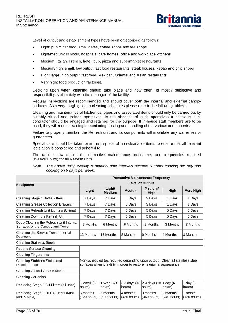
The table below details the corrective maintenance procedures and frequencies required (Weeks/Hours) for all Refresh units:
Note: The above daily, weekly & monthly time intervals assume 6 hours cooking per day and cooking on 5 days per week.
Preventive Maintenance Frequency
Level of Output Equipment
Light Light/
Medium Medium
Medium/High
High Very High
Cleaning Stage 1 Baffle Filters 7 Days 7 Days 5 Days 3 Days 1 Days 1 Days
Cleaning Grease Collection Drawers 7 Days 7 Days 5 Days 3 Days 1 Days 1 Days
Cleaning Refresh Unit Lighting (Ultima) 7 Days 7 Days 5 Days 5 Days 5 Days 5 Days
Cleaning Down the Refresh Unit 7 Days 7 Days 5 Days 5 Days 5 Days 5 Days
Deep Cleaning the Refresh Unit Internal Surfaces of the Canopy and Tower
6 Months 6 Months 6 Months 5 Months 3 Months 3 Months
Cleaning the Service Tower Internal Ductwork
12 Months 12 Months 8 Months 6 Months 4 Months 3 Months
Cleaning Stainless Steels
Routine Surface Cleaning
Cleaning Fingerprints
Cleaning Stubborn Stains and Discolouration
Cleaning Oil and Grease Marks
Cleaning Corrosion
Non-scheduled (as required depending upon output). Clean all stainless steel surfaces when it is dirty in order to restore its original appearance]
Replacing Stage 2 G4 Filters (all units) 1 Week (30 hours)
1 Week (30 hours)
2-3 days (18 hours)
2-3 days (18 hours)
1 day (6 hours)
1 day (6 hours)
Replacing Stage 3 HEPA Filters (Mini, Midi & Maxi)
6 months (720 hours)
5 months (600 hours)
4 months (480 hours)
3 months (360 hours)
2 months (240 hours)
1 month (120 hours)
Page 36 of 70 Issue: Final
REFRESHINSTALLATION, OPERATION AND MAINTENANCE MANUAL
Maintenance
Issue: Final Page 37 of 70
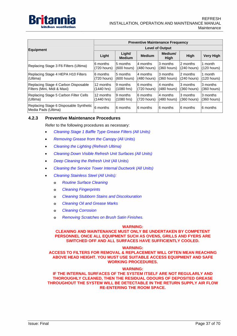
Preventive Maintenance Frequency
Level of Output Equipment
Light Light/
Medium Medium
Medium/ High
High Very High
Replacing Stage 3 F6 Filters (Ultima) 6 months (720 hours)
5 months (600 hours)
4 months (480 hours)
3 months (360 hours)
2 months (240 hours)
1 month (120 hours)
Replacing Stage 4 HEPA H10 Filters (Ultima)
6 months (720 hours)
5 months (600 hours)
4 months (480 hours)
3 months (360 hours)
2 months (240 hours)
1 month (120 hours)
Replacing Stage 4 Carbon Disposable Filters (Mini, Midi & Maxi)
12 months (1440 hrs)
9 months (1080 hrs)
6 months (720 hours)
4 months (480 hours)
3 months (360 hours)
3 months (360 hours)
Replacing Stage 5 Carbon Filter Cells (Ultima)
12 months (1440 hrs)
9 months (1080 hrs)
6 months (720 hours)
4 months (480 hours)
3 months (360 hours)
3 months (360 hours)
Replacing Stage 6 Disposable Synthetic Media Pads (Ultima)
6 months 6 months 6 months 6 months 6 months 6 months
4.2.3 Preventive Maintenance Procedures
Refer to the following procedures as necessary:
Cleaning Stage 1 Baffle Type Grease Filters (All Units)
Removing Grease from the Canopy (All Units)
Cleaning the Lighting (Refresh Ultima)
Cleaning Down Visible Refresh Unit Surfaces (All Units)
Deep Cleaning the Refresh Unit (All Units)
Cleaning the Service Tower Internal Ductwork (All Units)
Cleaning Stainless Steel (All Units):
o Routine Surface Cleaning
o Cleaning Fingerprints
o Cleaning Stubborn Stains and Discolouration
o Cleaning Oil and Grease Marks
o Cleaning Corrosion
o Removing Scratches on Brush Satin Finishes.
WARNING: CLEANING AND MAINTENANCE MUST ONLY BE UNDERTAKEN BY COMPETENT PERSONNEL ONCE ALL EQUIPMENT SUCH AS OVENS, GRILLS AND FYERS ARE
SWITCHED OFF AND ALL SURFACES HAVE SUFFICIENTLY COOLED.
WARNING: ACCESS TO FILTERS FOR REMOVAL & REPLACEMENT WILL OFTEN MEAN REACHING
ABOVE HEAD HEIGHT. YOU MUST USE SUITABLE ACCESS EQUIPMENT AND SAFE WORKING PROCEDURES.
WARNING: IF THE INTERNAL SURFACES OF THE SYSTEM ITSELF ARE NOT REGULARLY AND THOROUGHLY CLEANED, THEN THE RESIDUAL ODOURS OF DEPOSITED GREASE
THROUGHOUT THE SYSTEM WILL BE DETECTABLE IN THE RETURN SUPPLY AIR FLOW RE-ENTERING THE ROOM SPACE.
REFRESH INSTALLATION, OPERATION AND MAINTENANCE MANUAL Maintenance
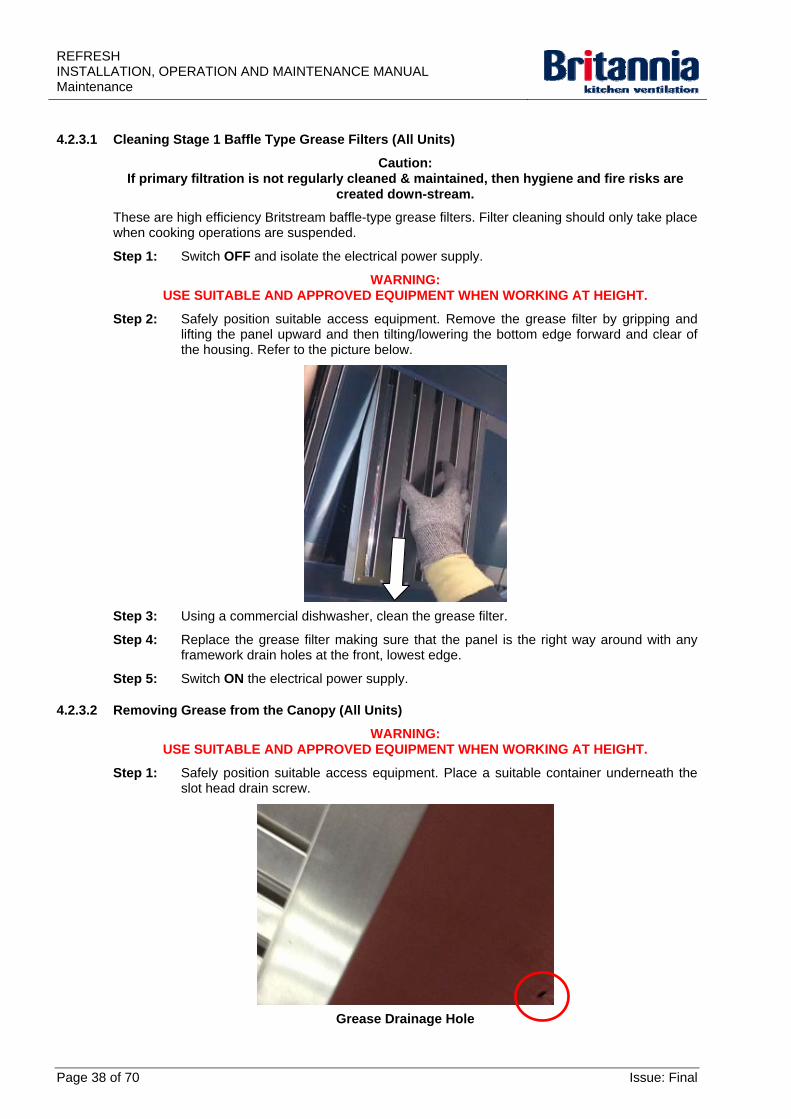
4.2.3.1 Cleaning Stage 1 Baffle Type Grease Filters (All Units)
Caution: If primary filtration is not regularly cleaned & maintained, then hygiene and fire risks are
created down-stream.
These are high efficiency Britstream baffle-type grease filters. Filter cleaning should only take place when cooking operations are suspended.
Step 1: Switch OFF and isolate the electrical power supply.
WARNING: USE SUITABLE AND APPROVED EQUIPMENT WHEN WORKING AT HEIGHT.
Step 2: Safely position suitable access equipment. Remove the grease filter by gripping and lifting the panel upward and then tilting/lowering the bottom edge forward and clear of the housing. Refer to the picture below.
Step 3: Using a commercial dishwasher, clean the grease filter.
Step 4: Replace the grease filter making sure that the panel is the right way around with any framework drain holes at the front, lowest edge.
Step 5: Switch ON the electrical power supply.
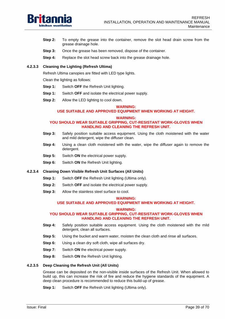
4.2.3.2 Removing Grease from the Canopy (All Units)
WARNING: USE SUITABLE AND APPROVED EQUIPMENT WHEN WORKING AT HEIGHT.
Step 1: Safely position suitable access equipment. Place a suitable container underneath the slot head drain screw.
Grease Drainage Hole
Page 38 of 70 Issue: Final
REFRESHINSTALLATION, OPERATION AND MAINTENANCE MANUAL
Maintenance
Step 2: To empty the grease into the container, remove the slot head drain screw from the grease drainage hole.
Step 3: Once the grease has been removed, dispose of the container.
Step 4: Replace the slot head screw back into the grease drainage hole.
4.2.3.3 Cleaning the Lighting (Refresh Ultima)
Refresh Ultima canopies are fitted with LED type lights.
Clean the lighting as follows:
Step 1: Switch OFF the Refresh Unit lighting.
Step 1: Switch OFF and isolate the electrical power supply.
Step 2: Allow the LED lighting to cool down.
WARNING: USE SUITABLE AND APPROVED EQUIPMENT WHEN WORKING AT HEIGHT.
WARNING: YOU SHOULD WEAR SUITABLE GRIPPING, CUT-RESISTANT WORK-GLOVES WHEN
HANDLING AND CLEANING THE REFRESH UNIT.
Step 3: Safely position suitable access equipment. Using the cloth moistened with the water and mild detergent, wipe the diffuser clean.
Step 4: Using a clean cloth moistened with the water, wipe the diffuser again to remove the detergent.
Step 5: Switch ON the electrical power supply.
Step 6: Switch ON the Refresh Unit lighting.
4.2.3.4 Cleaning Down Visible Refresh Unit Surfaces (All Units)
Step 1: Switch OFF the Refresh Unit lighting (Ultima only).
Step 2: Switch OFF and isolate the electrical power supply.
Step 3: Allow the stainless steel surface to cool.
WARNING: USE SUITABLE AND APPROVED EQUIPMENT WHEN WORKING AT HEIGHT.
WARNING: YOU SHOULD WEAR SUITABLE GRIPPING, CUT-RESISTANT WORK-GLOVES WHEN
HANDLING AND CLEANING THE REFRESH UNIT.
Step 4: Safely position suitable access equipment. Using the cloth moistened with the mild detergent, clean all surfaces.
Step 5: Using the bucket and warm water, moisten the clean cloth and rinse all surfaces.
Step 6: Using a clean dry soft cloth, wipe all surfaces dry.
Step 7: Switch ON the electrical power supply.
Step 8: Switch ON the Refresh Unit lighting.
4.2.3.5 Deep Cleaning the Refresh Unit (All Units)
Grease can be deposited on the non-visible inside surfaces of the Refresh Unit. When allowed to build up, this can increase the risk of fire and reduce the hygiene standards of the equipment. A deep clean procedure is recommended to reduce this build-up of grease.
Step 1: Switch OFF the Refresh Unit lighting (Ultima only).
Issue: Final Page 39 of 70
REFRESH INSTALLATION, OPERATION AND MAINTENANCE MANUAL Maintenance
Step 2: Switch OFF and isolate the electrical power supply.
Step 3: Allow the stainless steel surfaces to cool.
WARNING: USE SUITABLE AND APPROVED EQUIPMENT WHEN WORKING AT HEIGHT.
WARNING: YOU SHOULD WEAR SUITABLE GRIPPING, CUT-RESISTANT WORK-GLOVES WHEN
HANDLING AND CLEANING THE REFRESH UNIT.
Step 4: Safely position suitable access equipment. Using the cloth moistened with the Acetone or the Alcohol, clean all surfaces to remove oil and grease.
Step 5: Using the bucket and warm water, moisten the clean cloth and rinse all surfaces.
Step 6: Using a clean dry soft cloth, wipe all surfaces dry.
Step 7: Switch ON the electrical power supply.
Step 8: Switch ON the Refresh Unit lighting.
4.2.3.6 Cleaning the Service Tower Internal Ductwork (All Units)
Step 1: Clean the internal ductwork of the Refresh unit. Refer to Section 4.2.3.1.7 Cleaning Stainless Steel - ‘Cleaning Oil and Grease Marks’ below.
4.2.3.7 Cleaning Stainless Steel (All Units)
In general, stainless steel cleaning is carried out to restore the original surface appearance to prevent corrosion and maintain hygiene standards.
All grades of stainless steel will stain and discolour due to surface deposits and can never be accepted as completely maintenance free. In order to achieve maximum corrosion resistance the surface of the stainless steel must be kept clean.
Refer to the following procedures in this section as necessary:
Routine Surface Cleaning
Cleaning Fingerprints
Cleaning Stubborn Stains and Discolouration
Cleaning Oil and Grease Marks
Cleaning Corrosion
Removing Scratches on Brush Satin Finishes.
4.2.3.7.1 Routine Surface Cleaning
Step 1: Switch OFF and isolate the electrical power supply.
Step 2: Allow the stainless steel surface to cool.
WARNING: CLEANING AND MAINTENANCE MUST ONLY BE UNDERTAKEN BY COMPETENT PERSONNEL ONCE ALL EQUIPMENT SUCH AS OVENS, GRILLS AND FYERS ARE
SWITCHED OFF AND ALL SURFACES HAVE SUFFICIENTLY COOLED.
WARNING: USE SUITABLE AND APPROVED EQUIPMENT WHEN WORKING AT HEIGHT.
WARNING: YOU SHOULD WEAR SUITABLE GRIPPING, CUT-RESISTANT WORK-GLOVES WHEN
HANDLING AND CLEANING THE REFRESH UNIT.
Page 40 of 70 Issue: Final
REFRESHINSTALLATION, OPERATION AND MAINTENANCE MANUAL
Maintenance
Step 3: Safely position suitable access equipment. Using the cloth moistened with the mild detergent, clean all surfaces.
Step 4: Using the bucket and warm water, moisten the clean cloth and rinse all surfaces.
Step 5: Using a clean dry soft cloth, wipe all surfaces dry.
Step 6: Switch ON the electrical power supply.
4.2.3.7.2 Cleaning Fingerprints
Step 1: Switch OFF and isolate the electrical power supply.
Step 2: Allow the stainless steel surface to cool.
WARNING: CLEANING AND MAINTENANCE MUST ONLY BE UNDERTAKEN BY COMPETENT PERSONNEL ONCE ALL EQUIPMENT SUCH AS OVENS, GRILLS AND FYERS ARE
SWITCHED OFF AND ALL SURFACES HAVE SUFFICIENTLY COOLED.
WARNING: USE SUITABLE AND APPROVED EQUIPMENT WHEN WORKING AT HEIGHT.
WARNING: YOU SHOULD WEAR SUITABLE GRIPPING, CUT-RESISTANT WORK-GLOVES WHEN
HANDLING AND CLEANING THE REFRESH UNIT.
Step 3: Safely position suitable access equipment. Using the cloth and mild detergent, clean all surfaces.
Step 4: Using the bucket and warm water, moisten the clean cloth and rinse all surfaces.
Note: An organic solvent such as Acetone and Alcohol can also be used
Step 5: Using a clean dry soft cloth, wipe all surfaces dry.
Step 6: Switch ON the electrical power supply.
4.2.3.7.3 Cleaning Stubborn Stains and Discolouration
Step 1: Switch OFF and isolate the electrical power supply.
Step 2: Allow the stainless steel surface to cool.
WARNING: CLEANING AND MAINTENANCE MUST ONLY BE UNDERTAKEN BY COMPETENT PERSONNEL ONCE ALL EQUIPMENT SUCH AS OVENS, GRILLS AND FYERS ARE
SWITCHED OFF AND ALL SURFACES HAVE SUFFICIENTLY COOLED.
WARNING: USE SUITABLE AND APPROVED EQUIPMENT WHEN WORKING AT HEIGHT.
WARNING: YOU SHOULD WEAR SUITABLE GRIPPING, CUT-RESISTANT WORK-GLOVES WHEN
HANDLING AND CLEANING THE REFRESH UNIT.
Step 3: Safely position suitable access equipment. Using the cloth moistened with the cleaning cream, clean all surfaces.
Step 4: Using the bucket and warm water, moisten the clean cloth and rinse all surfaces.
Step 5: Using a clean dry soft cloth, wipe all surfaces dry.
Step 6: Switch ON the electrical power supply.
Issue: Final Page 41 of 70
REFRESH INSTALLATION, OPERATION AND MAINTENANCE MANUAL Maintenance
4.2.3.7.4 Cleaning Oil and Grease Marks
Step 1: Switch OFF and isolate the electrical power supply.
Step 2: Allow the stainless steel surface to cool.
WARNING: CLEANING AND MAINTENANCE MUST ONLY BE UNDERTAKEN BY COMPETENT PERSONNEL ONCE ALL EQUIPMENT SUCH AS OVENS, GRILLS AND FYERS ARE
SWITCHED OFF AND ALL SURFACES HAVE SUFFICIENTLY COOLED.
WARNING: USE SUITABLE AND APPROVED EQUIPMENT WHEN WORKING AT HEIGHT.
WARNING: YOU SHOULD WEAR SUITABLE GRIPPING, CUT-RESISTANT WORK-GLOVES WHEN
HANDLING AND CLEANING THE REFRESH UNIT.
Step 3: Safely position suitable access equipment. Using the cloth and mild detergent, clean all surfaces.
Note: An organic solvent such as Acetone and Alcohol can also be used
Step 4: Using the bucket and warm water, moisten the clean cloth and rinse all surfaces.
Step 5: Using a clean dry soft cloth, wipe all surfaces dry.
Step 6: Switch ON the electrical power supply.
4.2.3.7.5 Cleaning Corrosion
Step 1: Switch OFF and isolate the electrical power supply.
Step 2: Allow the stainless steel surface to cool.
WARNING: CLEANING AND MAINTENANCE MUST ONLY BE UNDERTAKEN BY COMPETENT PERSONNEL ONCE ALL EQUIPMENT SUCH AS OVENS, GRILLS AND FYERS ARE
SWITCHED OFF AND ALL SURFACES HAVE SUFFICIENTLY COOLED.
WARNING: USE SUITABLE AND APPROVED EQUIPMENT WHEN WORKING AT HEIGHT.
WARNING: YOU MUST WEAR SUITABLE RUBBER GLOVES WHEN CLEANING WITH ANY ACID
SOLUTIONS. SPECIAL PRECAUTIONS ARE NECESSARY WITH OXALIC ACID. SOLVENTS SHOULD NOT BE USED IN ENCLOSED PLACES.
Step 3: Safely position suitable access equipment. Using the rubber gloves and the swab moistened with the oxalic acid, wet the corroded surface and allow to the acid to stand for 14 to 20 minutes.
Step 4: Using the rubber gloves and clean warm water, wash the oxalic acid away.
WARNING: YOU SHOULD WEAR SUITABLE GRIPPING, CUT-RESISTANT WORK-GLOVES WHEN
HANDLING AND CLEANING THE REFRESH UNIT.
Step 5: Using the cloth moistened with the cleaning cream, clean the surfaces where the oxalic acid was applied.
WARNING: YOU SHOULD WEAR SUITABLE GRIPPING, CUT-RESISTANT WORK-GLOVES WHEN
HANDLING AND CLEANING THE REFRESH UNIT.
Step 6: Using the bucket and warm water, moisten the clean cloth and rinse the surfaces where the cleaning cream was applied.
Step 7: Using a clean dry soft cloth, wipe the surfaces dry.
Step 8: Switch ON the electrical power supply.
Page 42 of 70 Issue: Final
REFRESHINSTALLATION, OPERATION AND MAINTENANCE MANUAL
Maintenance
4.2.3.7.6 Removing Scratches on Brush Satin Finishes
Step 1: Switch OFF and isolate the electrical power supply.
Step 2: Allow the stainless steel surface to cool.
WARNING: CLEANING AND MAINTENANCE MUST ONLY BE UNDERTAKEN BY COMPETENT PERSONNEL ONCE ALL EQUIPMENT SUCH AS OVENS, GRILLS AND FYERS ARE
SWITCHED OFF AND ALL SURFACES HAVE SUFFICIENTLY COOLED.
WARNING: USE SUITABLE AND APPROVED EQUIPMENT WHEN WORKING AT HEIGHT.
WARNING: YOU SHOULD WEAR SUITABLE GRIPPING, CUT-RESISTANT WORK-GLOVES WHEN
HANDLING AND CLEANING THE REFRESH UNIT.
Step 3: Safely position suitable access equipment. Treat surface scratches as follows:
Step a) For light surface scratches; use the nylon pads to gently remove the scratches.
Step b) For deep surface scratches; use the scurf’s in the direction of polishing to remove the scratches.
Step 4: Switch ON the electrical power supply.
4.2.3.8 Recommended Cleaning and Maintenance Contractors
Britannia can provide a range of maintenance services, from a full maintenance contract including cleaning and replacement of filters, to individual service calls and onsite training.
4.2.3.9 Maintenance of Fire Suppression Systems (Where Installed)
Contact details of appropriate companies can be supplied if required.
Issue: Final Page 43 of 70
REFRESH INSTALLATION, OPERATION AND MAINTENANCE MANUAL Maintenance
4.3 Fault Finding
4.3.1 Fault Finding Procedures
4.3.1.1 Filter Status Screens
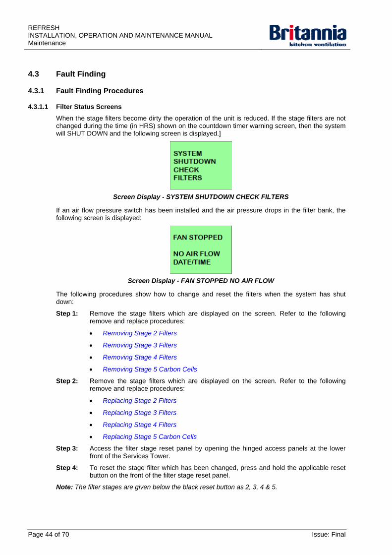
When the stage filters become dirty the operation of the unit is reduced. If the stage filters are not changed during the time (in HRS) shown on the countdown timer warning screen, then the system will SHUT DOWN and the following screen is displayed.]
Screen Display - SYSTEM SHUTDOWN CHECK FILTERS
If an air flow pressure switch has been installed and the air pressure drops in the filter bank, the following screen is displayed:
Screen Display - FAN STOPPED NO AIR FLOW
The following procedures show how to change and reset the filters when the system has shut down:
Step 1: Remove the stage filters which are displayed on the screen. Refer to the following remove and replace procedures:
Removing Stage 2 Filters
Removing Stage 3 Filters
Removing Stage 4 Filters
Removing Stage 5 Carbon Cells
Step 2: Remove the stage filters which are displayed on the screen. Refer to the following remove and replace procedures:
Replacing Stage 2 Filters
Replacing Stage 3 Filters
Replacing Stage 4 Filters
Replacing Stage 5 Carbon Cells
Step 3: Access the filter stage reset panel by opening the hinged access panels at the lower front of the Services Tower.
Step 4: To reset the stage filter which has been changed, press and hold the applicable reset button on the front of the filter stage reset panel.
Note: The filter stages are given below the black reset button as 2, 3, 4 & 5.
Page 44 of 70 Issue: Final
REFRESHINSTALLATION, OPERATION AND MAINTENANCE MANUAL
Maintenance
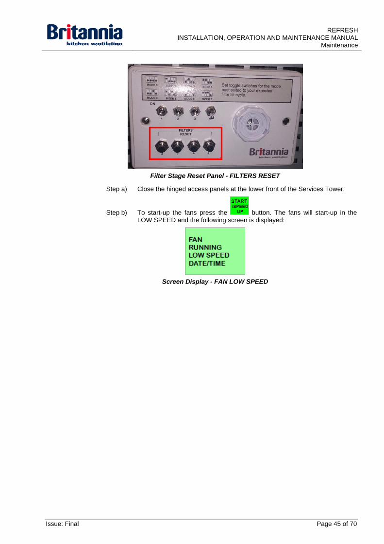
Filter Stage Reset Panel - FILTERS RESET
Step a) Close the hinged access panels at the lower front of the Services Tower.
Step b) To start-up the fans press the button. The fans will start-up in the LOW SPEED and the following screen is displayed:
Screen Display - FAN LOW SPEED
Issue: Final Page 45 of 70
REFRESH INSTALLATION, OPERATION AND MAINTENANCE MANUAL Maintenance
4.4 Corrective Maintenance
4.4.1 Maintenance Policy
Only suitably trained and competent personnel must carry out maintenance. Refer to Section 4.2.3.8 Recommended Cleaning and Maintenance Contractors for details of contractors suitable to maintain the equipment.
4.4.2 Removal Procedures (Refresh Mini, Midi & Maxi)
Refer to the following procedures as necessary:
Removing Stage 2 Filters
Removing Stage 3 Filters
Removing Stage 4 Carbon Filters
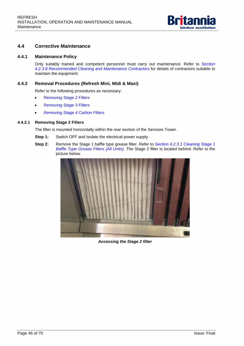
4.4.2.1 Removing Stage 2 Filters
The filter is mounted horizontally within the rear section of the Services Tower.
Step 1: Switch OFF and isolate the electrical power supply.
Step 2: Remove the Stage 1 baffle type grease filter. Refer to Section 4.2.3.1 Cleaning Stage 1 Baffle Type Grease Filters (All Units). The Stage 2 filter is located behind. Refer to the picture below.
Accessing the Stage 2 filter
Page 46 of 70 Issue: Final
REFRESHINSTALLATION, OPERATION AND MAINTENANCE MANUAL
Maintenance
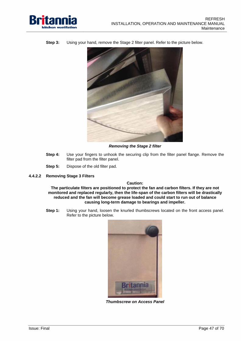
Step 3: Using your hand, remove the Stage 2 filter panel. Refer to the picture below.
Removing the Stage 2 filter
Step 4: Use your fingers to unhook the securing clip from the filter panel flange. Remove the filter pad from the filter panel.
Step 5: Dispose of the old filter pad.
4.4.2.2 Removing Stage 3 Filters
Caution: The particulate filters are positioned to protect the fan and carbon filters. If they are not
monitored and replaced regularly, then the life-span of the carbon filters will be drastically reduced and the fan will become grease loaded and could start to run out of balance
causing long-term damage to bearings and impeller.
Step 1: Using your hand, loosen the knurled thumbscrews located on the front access panel. Refer to the picture below.
Thumbscrew on Access Panel
Issue: Final Page 47 of 70
REFRESH INSTALLATION, OPERATION AND MAINTENANCE MANUAL Maintenance
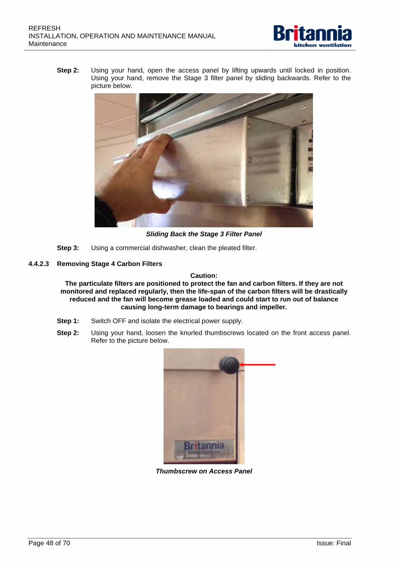
Step 2: Using your hand, open the access panel by lifting upwards until locked in position. Using your hand, remove the Stage 3 filter panel by sliding backwards. Refer to the picture below.
Sliding Back the Stage 3 Filter Panel
Step 3: Using a commercial dishwasher, clean the pleated filter.
4.4.2.3 Removing Stage 4 Carbon Filters
Caution: The particulate filters are positioned to protect the fan and carbon filters. If they are not
monitored and replaced regularly, then the life-span of the carbon filters will be drastically reduced and the fan will become grease loaded and could start to run out of balance
causing long-term damage to bearings and impeller.
Step 1: Switch OFF and isolate the electrical power supply.
Step 2: Using your hand, loosen the knurled thumbscrews located on the front access panel. Refer to the picture below.
Thumbscrew on Access Panel
Page 48 of 70 Issue: Final
REFRESHINSTALLATION, OPERATION AND MAINTENANCE MANUAL
Maintenance
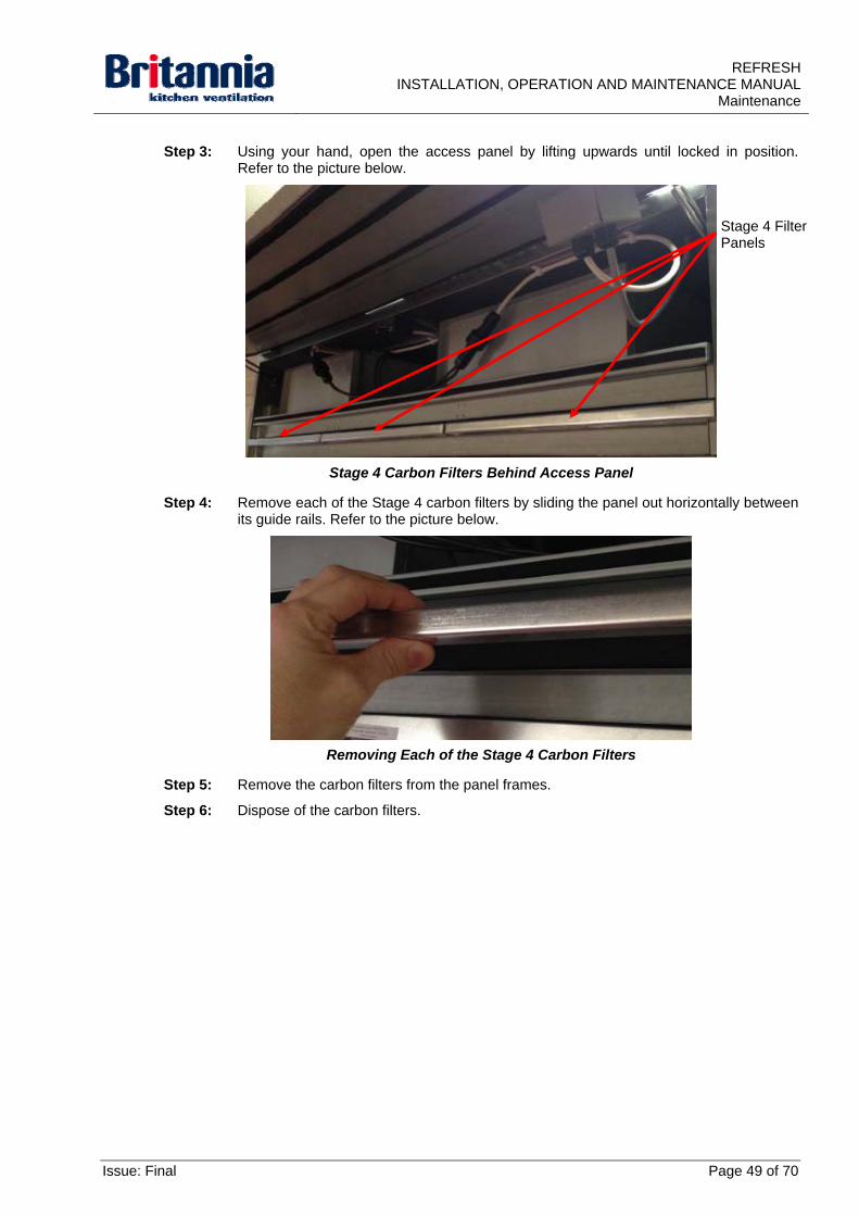
Step 3: Using your hand, open the access panel by lifting upwards until locked in position. Refer to the picture below.
Stage 4 Carbon Filters Behind Access Panel
Stage 4 Filter Panels
Step 4: Remove each of the Stage 4 carbon filters by sliding the panel out horizontally between its guide rails. Refer to the picture below.
Removing Each of the Stage 4 Carbon Filters
Step 5: Remove the carbon filters from the panel frames.
Step 6: Dispose of the carbon filters.
Issue: Final Page 49 of 70
REFRESH INSTALLATION, OPERATION AND MAINTENANCE MANUAL Maintenance
4.4.3 Removal Procedures (Refresh Ultima)
Refer to the following procedures as necessary:
Removing Stage 2 Filters
Removing Stage 3 Filters
Removing Stage 4 Filters
Removing Stage 5 Carbon Cells
Removing an LED Lamp
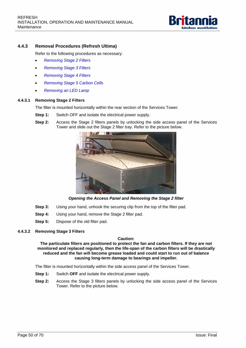
4.4.3.1 Removing Stage 2 Filters
The filter is mounted horizontally within the rear section of the Services Tower.
Step 1: Switch OFF and isolate the electrical power supply.
Step 2: Access the Stage 2 filters panels by unlocking the side access panel of the Services Tower and slide out the Stage 2 filter tray. Refer to the picture below.
Opening the Access Panel and Removing the Stage 2 filter
Step 3: Using your hand, unhook the securing clip from the top of the filter pad.
Step 4: Using your hand, remove the Stage 2 filter pad.
Step 5: Dispose of the old filter pad.
4.4.3.2 Removing Stage 3 Filters
Caution: The particulate filters are positioned to protect the fan and carbon filters. If they are not
monitored and replaced regularly, then the life-span of the carbon filters will be drastically reduced and the fan will become grease loaded and could start to run out of balance
causing long-term damage to bearings and impeller.
The filter is mounted horizontally within the side access panel of the Services Tower.
Step 1: Switch OFF and isolate the electrical power supply.
Step 2: Access the Stage 3 filters panels by unlocking the side access panel of the Services Tower. Refer to the picture below.
Page 50 of 70 Issue: Final
REFRESHINSTALLATION, OPERATION AND MAINTENANCE MANUAL
Maintenance
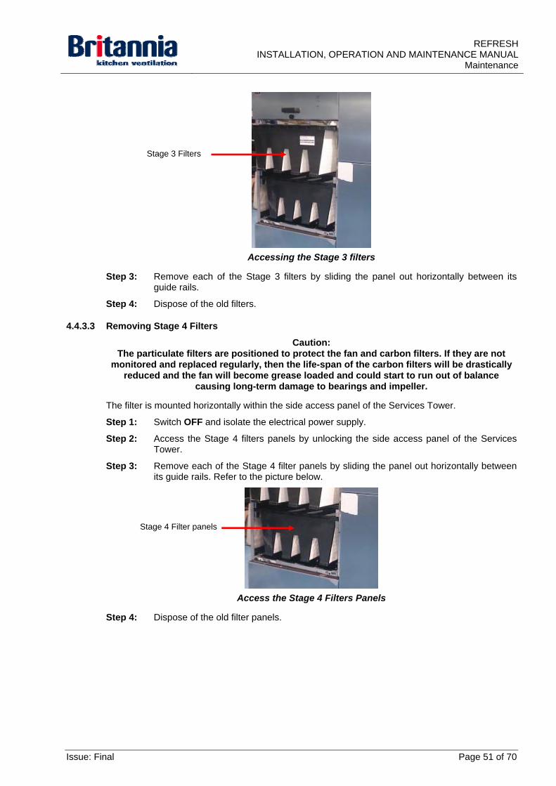
Accessing the Stage 3 filters
Stage 3 Filters
Step 3: Remove each of the Stage 3 filters by sliding the panel out horizontally between its guide rails.
Step 4: Dispose of the old filters.
4.4.3.3 Removing Stage 4 Filters
Caution: The particulate filters are positioned to protect the fan and carbon filters. If they are not
monitored and replaced regularly, then the life-span of the carbon filters will be drastically reduced and the fan will become grease loaded and could start to run out of balance
causing long-term damage to bearings and impeller.
The filter is mounted horizontally within the side access panel of the Services Tower.
Step 1: Switch OFF and isolate the electrical power supply.
Step 2: Access the Stage 4 filters panels by unlocking the side access panel of the Services Tower.
Step 3: Remove each of the Stage 4 filter panels by sliding the panel out horizontally between its guide rails. Refer to the picture below.
Access the Stage 4 Filters Panels
Stage 4 Filter panels
Step 4: Dispose of the old filter panels.
Issue: Final Page 51 of 70
REFRESH INSTALLATION, OPERATION AND MAINTENANCE MANUAL Maintenance
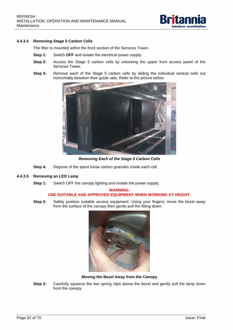
4.4.3.4 Removing Stage 5 Carbon Cells
The filter is mounted within the front section of the Services Tower.
Step 1: Switch OFF and isolate the electrical power supply.
Step 2: Access the Stage 5 carbon cells by unlocking the upper front access panel of the Services Tower.
Step 3: Remove each of the Stage 5 carbon cells by sliding the individual vertical cells out horizontally between their guide rails. Refer to the picture below.
Removing Each of the Stage 5 Carbon Cells
Step 4: Dispose of the spent loose carbon granules inside each cell.
4.4.3.5 Removing an LED Lamp
Step 1: Switch OFF the canopy lighting and isolate the power supply.
WARNING: USE SUITABLE AND APPROVED EQUIPMENT WHEN WORKING AT HEIGHT.
Step 2: Safely position suitable access equipment. Using your fingers, move the bezel away from the surface of the canopy then gently pull the fitting down.
Moving the Bezel Away from the Canopy
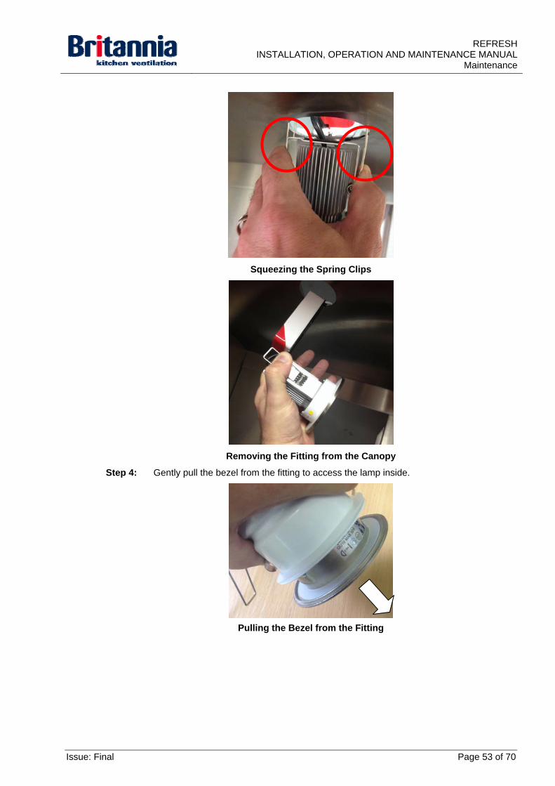
Step 3: Carefully squeeze the two spring clips above the bezel and gently pull the lamp down from the canopy.
Page 52 of 70 Issue: Final
REFRESHINSTALLATION, OPERATION AND MAINTENANCE MANUAL
Maintenance
Squeezing the Spring Clips
Removing the Fitting from the Canopy
Step 4: Gently pull the bezel from the fitting to access the lamp inside.
Pulling the Bezel from the Fitting
Issue: Final Page 53 of 70
REFRESH INSTALLATION, OPERATION AND MAINTENANCE MANUAL Maintenance
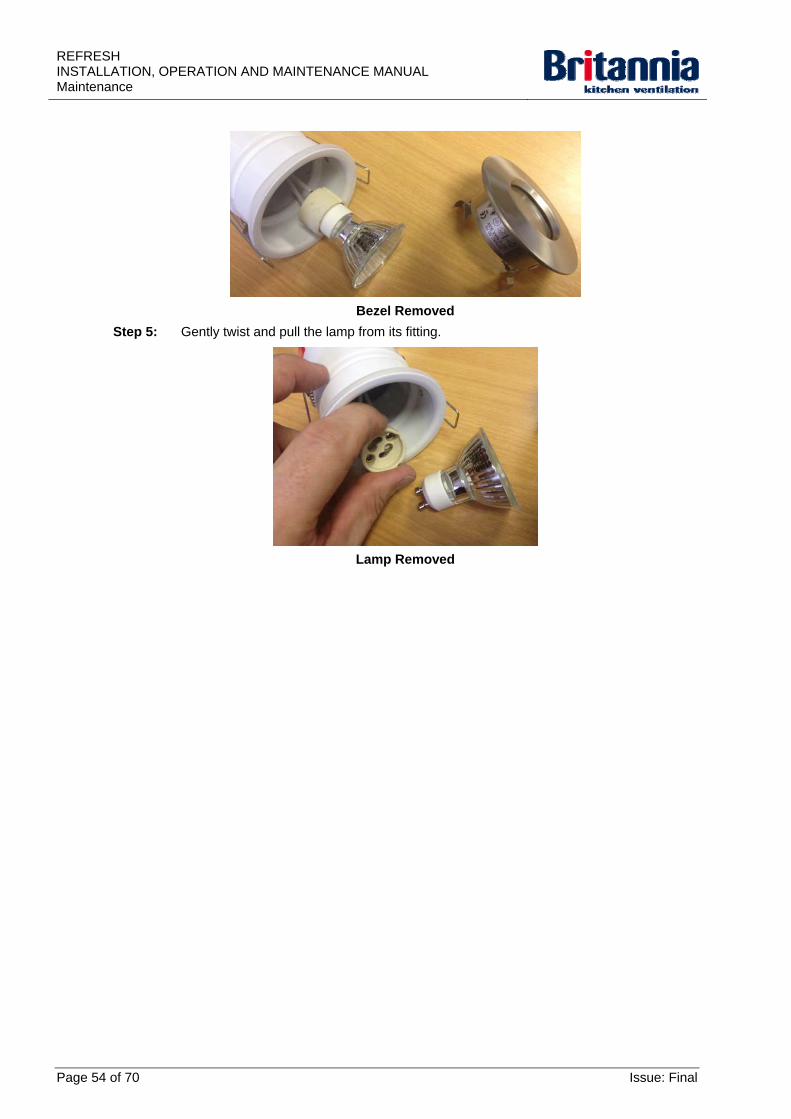
Bezel Removed
Step 5: Gently twist and pull the lamp from its fitting.
Lamp Removed
Page 54 of 70 Issue: Final
REFRESHINSTALLATION, OPERATION AND MAINTENANCE MANUAL
Maintenance
4.4.4 Replacement Procedures (Refresh Mini, Midi & Maxi)
Refer to the following procedures as necessary:
Replacing Stage 2 Filters
Replacing Stage 3 Filters
Replacing Stage 4 Carbon Filters
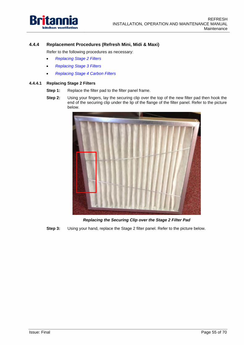
4.4.4.1 Replacing Stage 2 Filters
Step 1: Replace the filter pad to the filter panel frame.
Step 2: Using your fingers, lay the securing clip over the top of the new filter pad then hook the end of the securing clip under the lip of the flange of the filter panel. Refer to the picture below.
Replacing the Securing Clip over the Stage 2 Filter Pad
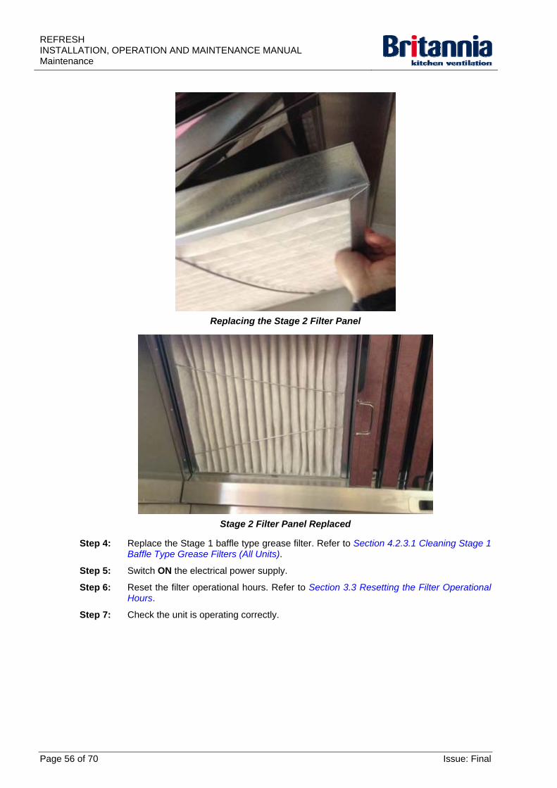
Step 3: Using your hand, replace the Stage 2 filter panel. Refer to the picture below.
Issue: Final Page 55 of 70
REFRESH INSTALLATION, OPERATION AND MAINTENANCE MANUAL Maintenance
Replacing the Stage 2 Filter Panel
Stage 2 Filter Panel Replaced
Step 4: Replace the Stage 1 baffle type grease filter. Refer to Section 4.2.3.1 Cleaning Stage 1 Baffle Type Grease Filters (All Units).
Step 5: Switch ON the electrical power supply.
Step 6: Reset the filter operational hours. Refer to Section 3.3 Resetting the Filter Operational Hours.
Step 7: Check the unit is operating correctly.
Page 56 of 70 Issue: Final
REFRESHINSTALLATION, OPERATION AND MAINTENANCE MANUAL
Maintenance
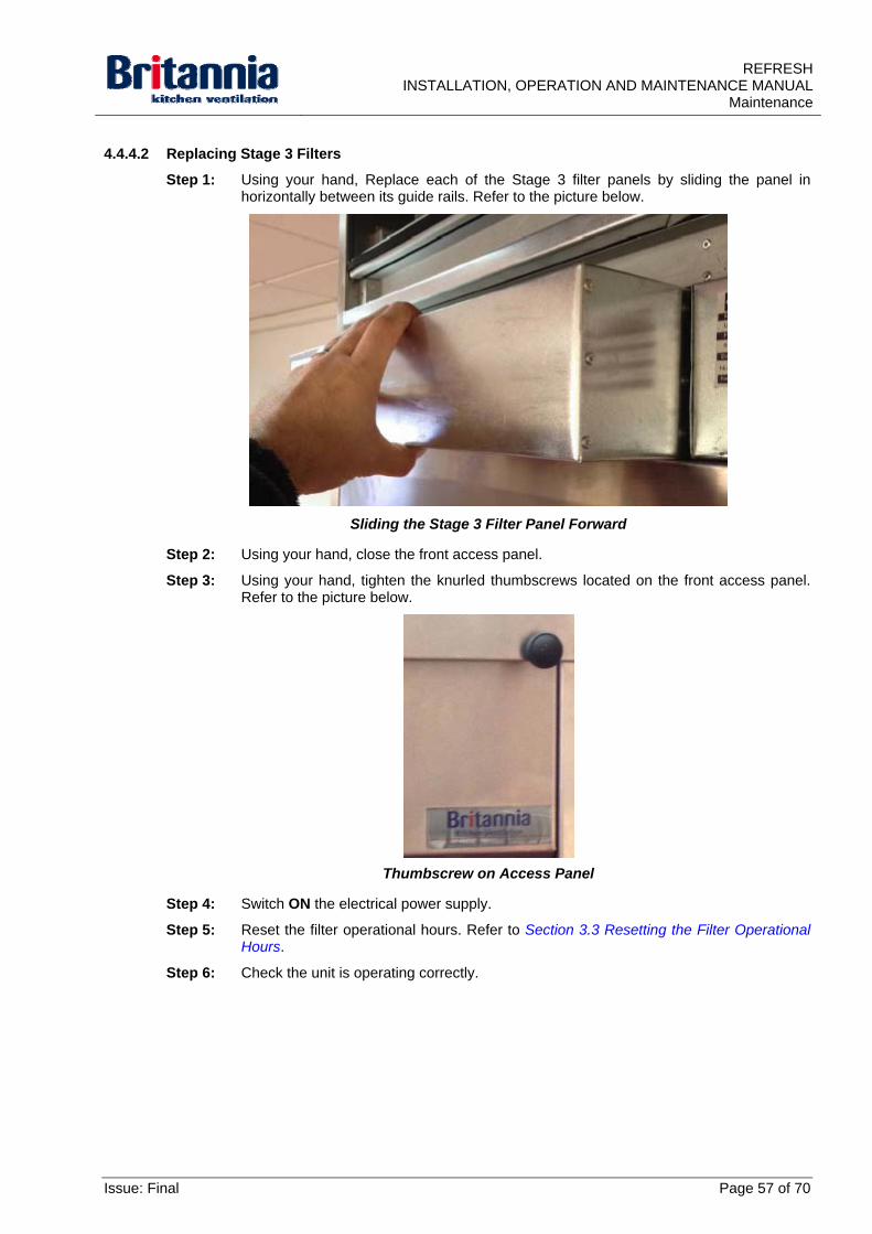
4.4.4.2 Replacing Stage 3 Filters
Step 1: Using your hand, Replace each of the Stage 3 filter panels by sliding the panel in horizontally between its guide rails. Refer to the picture below.
Sliding the Stage 3 Filter Panel Forward
Step 2: Using your hand, close the front access panel.
Step 3: Using your hand, tighten the knurled thumbscrews located on the front access panel. Refer to the picture below.
Thumbscrew on Access Panel
Step 4: Switch ON the electrical power supply.
Step 5: Reset the filter operational hours. Refer to Section 3.3 Resetting the Filter Operational Hours.
Step 6: Check the unit is operating correctly.
Issue: Final Page 57 of 70
REFRESH INSTALLATION, OPERATION AND MAINTENANCE MANUAL Maintenance
4.4.4.3 Replacing Stage 4 Carbon Filters
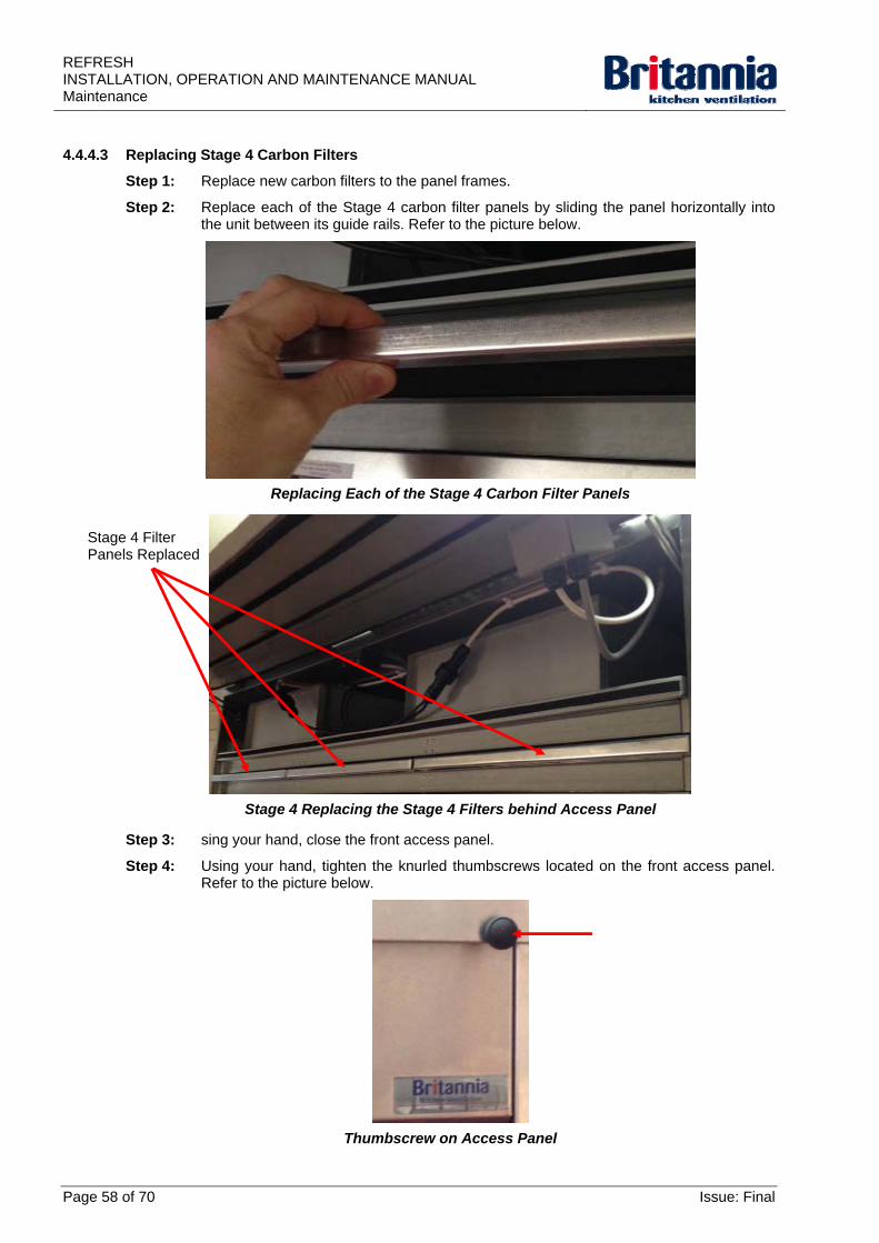
Step 1: Replace new carbon filters to the panel frames.
Step 2: Replace each of the Stage 4 carbon filter panels by sliding the panel horizontally into the unit between its guide rails. Refer to the picture below.
Replacing Each of the Stage 4 Carbon Filter Panels
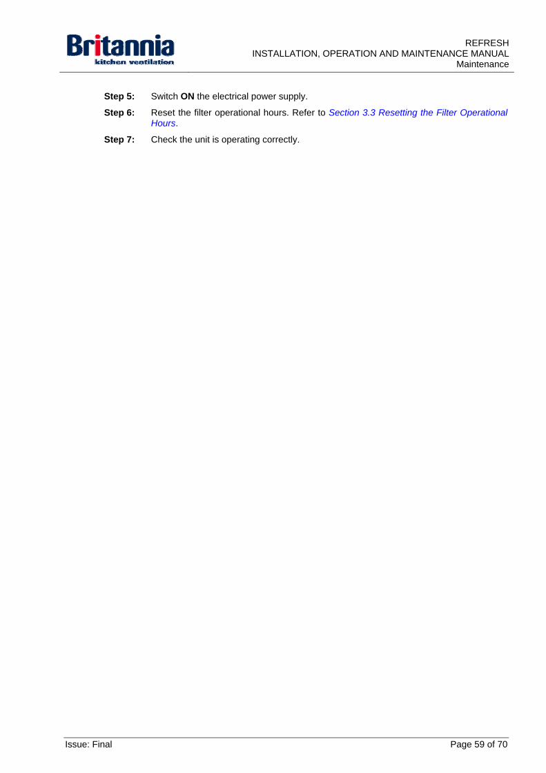
Stage 4 Replacing the Stage 4 Filters behind Access Panel
Stage 4 Filter Panels Replaced
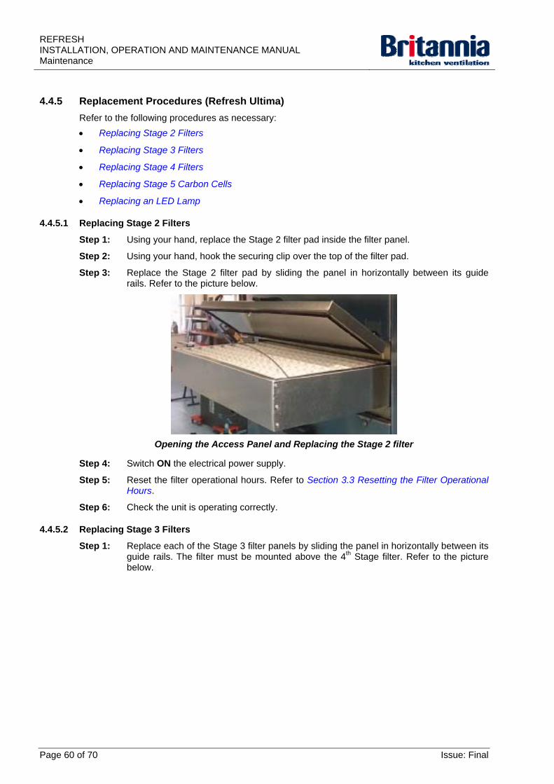
Step 3: sing your hand, close the front access panel.
Step 4: Using your hand, tighten the knurled thumbscrews located on the front access panel. Refer to the picture below.
Thumbscrew on Access Panel
Page 58 of 70 Issue: Final
REFRESHINSTALLATION, OPERATION AND MAINTENANCE MANUAL
Maintenance
Step 5: Switch ON the electrical power supply.
Step 6: Reset the filter operational hours. Refer to Section 3.3 Resetting the Filter Operational Hours.
Step 7: Check the unit is operating correctly.
Issue: Final Page 59 of 70
REFRESH INSTALLATION, OPERATION AND MAINTENANCE MANUAL Maintenance
4.4.5 Replacement Procedures (Refresh Ultima)
Refer to the following procedures as necessary:
Replacing Stage 2 Filters
Replacing Stage 3 Filters
Replacing Stage 4 Filters
Replacing Stage 5 Carbon Cells
Replacing an LED Lamp
4.4.5.1 Replacing Stage 2 Filters
Step 1: Using your hand, replace the Stage 2 filter pad inside the filter panel.
Step 2: Using your hand, hook the securing clip over the top of the filter pad.
Step 3: Replace the Stage 2 filter pad by sliding the panel in horizontally between its guide rails. Refer to the picture below.
Opening the Access Panel and Replacing the Stage 2 filter
Step 4: Switch ON the electrical power supply.
Step 5: Reset the filter operational hours. Refer to Section 3.3 Resetting the Filter Operational Hours.
Step 6: Check the unit is operating correctly.
4.4.5.2 Replacing Stage 3 Filters
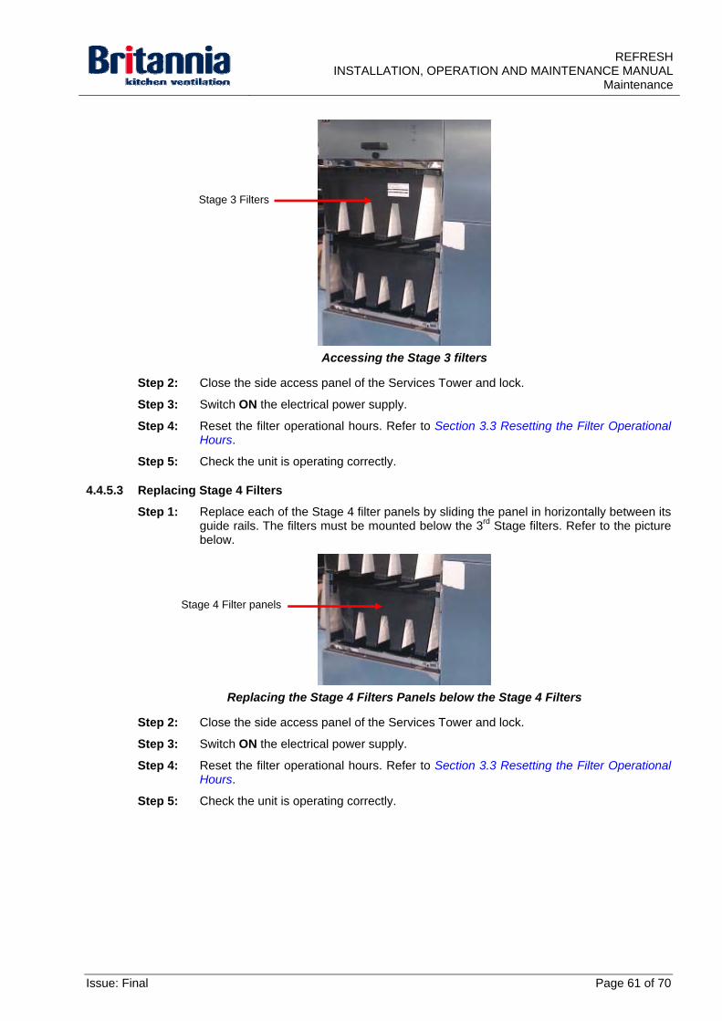
Step 1: Replace each of the Stage 3 filter panels by sliding the panel in horizontally between its guide rails. The filter must be mounted above the 4th Stage filter. Refer to the picture below.
Page 60 of 70 Issue: Final
REFRESHINSTALLATION, OPERATION AND MAINTENANCE MANUAL
Maintenance
Accessing the Stage 3 filters
Stage 3 Filters
Step 2: Close the side access panel of the Services Tower and lock.
Step 3: Switch ON the electrical power supply.
Step 4: Reset the filter operational hours. Refer to Section 3.3 Resetting the Filter Operational Hours.
Step 5: Check the unit is operating correctly.
4.4.5.3 Replacing Stage 4 Filters
Step 1: Replace each of the Stage 4 filter panels by sliding the panel in horizontally between its guide rails. The filters must be mounted below the 3rd Stage filters. Refer to the picture below.
Replacing the Stage 4 Filters Panels below the Stage 4 Filters
Stage 4 Filter panels
Step 2: Close the side access panel of the Services Tower and lock.
Step 3: Switch ON the electrical power supply.
Step 4: Reset the filter operational hours. Refer to Section 3.3 Resetting the Filter Operational Hours.
Step 5: Check the unit is operating correctly.
Issue: Final Page 61 of 70
REFRESH INSTALLATION, OPERATION AND MAINTENANCE MANUAL Maintenance
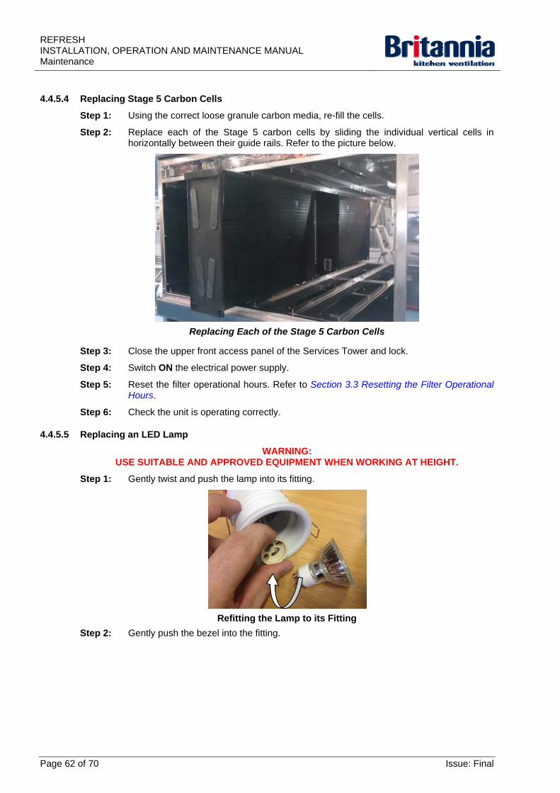
4.4.5.4 Replacing Stage 5 Carbon Cells
Step 1: Using the correct loose granule carbon media, re-fill the cells.
Step 2: Replace each of the Stage 5 carbon cells by sliding the individual vertical cells in horizontally between their guide rails. Refer to the picture below.
Replacing Each of the Stage 5 Carbon Cells
Step 3: Close the upper front access panel of the Services Tower and lock.
Step 4: Switch ON the electrical power supply.
Step 5: Reset the filter operational hours. Refer to Section 3.3 Resetting the Filter Operational Hours.
Step 6: Check the unit is operating correctly.
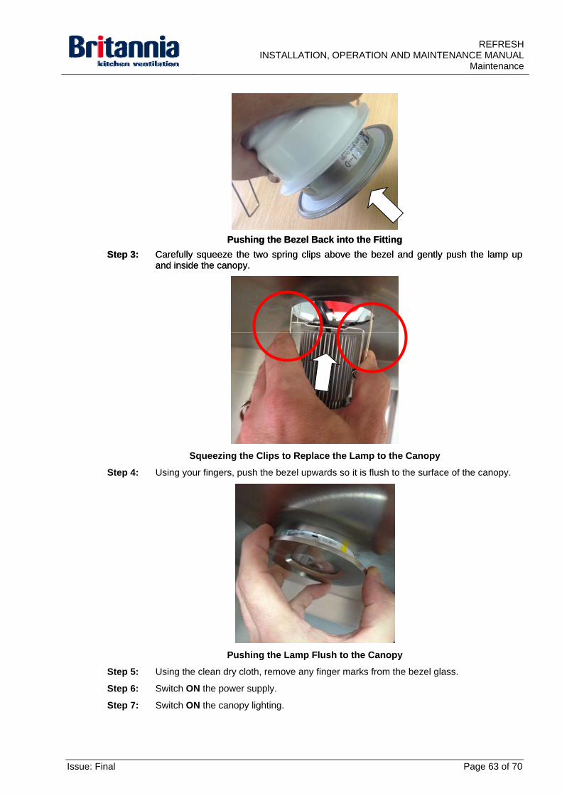
4.4.5.5 Replacing an LED Lamp
WARNING: USE SUITABLE AND APPROVED EQUIPMENT WHEN WORKING AT HEIGHT.
Step 1: Gently twist and push the lamp into its fitting.
Refitting the Lamp to its Fitting
Step 2: Gently push the bezel into the fitting.
Page 62 of 70 Issue: Final
REFRESHINSTALLATION, OPERATION AND MAINTENANCE MANUAL
Maintenance
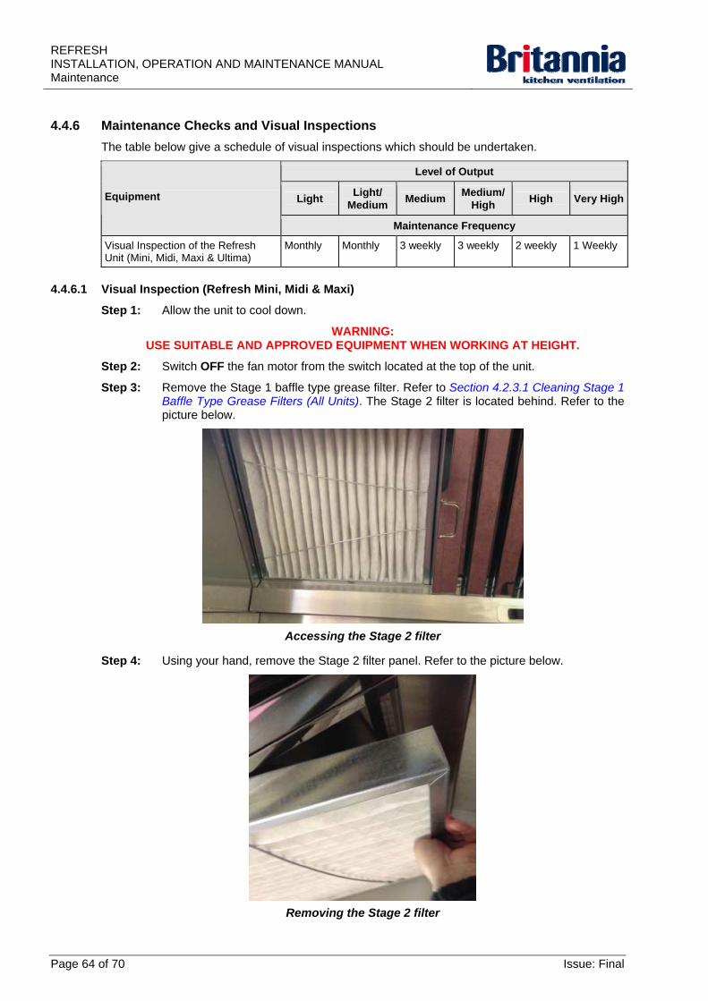
Pushing the Bezel Back into the Fitting Pushing the Bezel Back into the Fitting
Step 3: Carefully squeeze the two spring clips above the bezel and gently push the lamp up and inside the canopy.
Step 3: Carefully squeeze the two spring clips above the bezel and gently push the lamp up and inside the canopy.
Squeezing the Clips to Replace the Lamp to the Canopy
Step 4: Using your fingers, push the bezel upwards so it is flush to the surface of the canopy.
Pushing the Lamp Flush to the Canopy
Step 5: Using the clean dry cloth, remove any finger marks from the bezel glass.
Step 6: Switch ON the power supply.
Step 7: Switch ON the canopy lighting.
Issue: Final Page 63 of 70
REFRESH INSTALLATION, OPERATION AND MAINTENANCE MANUAL Maintenance
4.4.6 Maintenance Checks and Visual Inspections
The table below give a schedule of visual inspections which should be undertaken.
Level of Output
Light Light/
Medium Medium
Medium/ High
High Very HighEquipment
Maintenance Frequency
Visual Inspection of the Refresh Unit (Mini, Midi, Maxi & Ultima)
Monthly Monthly 3 weekly 3 weekly 2 weekly 1 Weekly
4.4.6.1 Visual Inspection (Refresh Mini, Midi & Maxi)
Step 1: Allow the unit to cool down.
WARNING: USE SUITABLE AND APPROVED EQUIPMENT WHEN WORKING AT HEIGHT.
Step 2: Switch OFF the fan motor from the switch located at the top of the unit.
Step 3: Remove the Stage 1 baffle type grease filter. Refer to Section 4.2.3.1 Cleaning Stage 1 Baffle Type Grease Filters (All Units). The Stage 2 filter is located behind. Refer to the picture below.
Accessing the Stage 2 filter
Step 4: Using your hand, remove the Stage 2 filter panel. Refer to the picture below.
Removing the Stage 2 filter
Page 64 of 70 Issue: Final
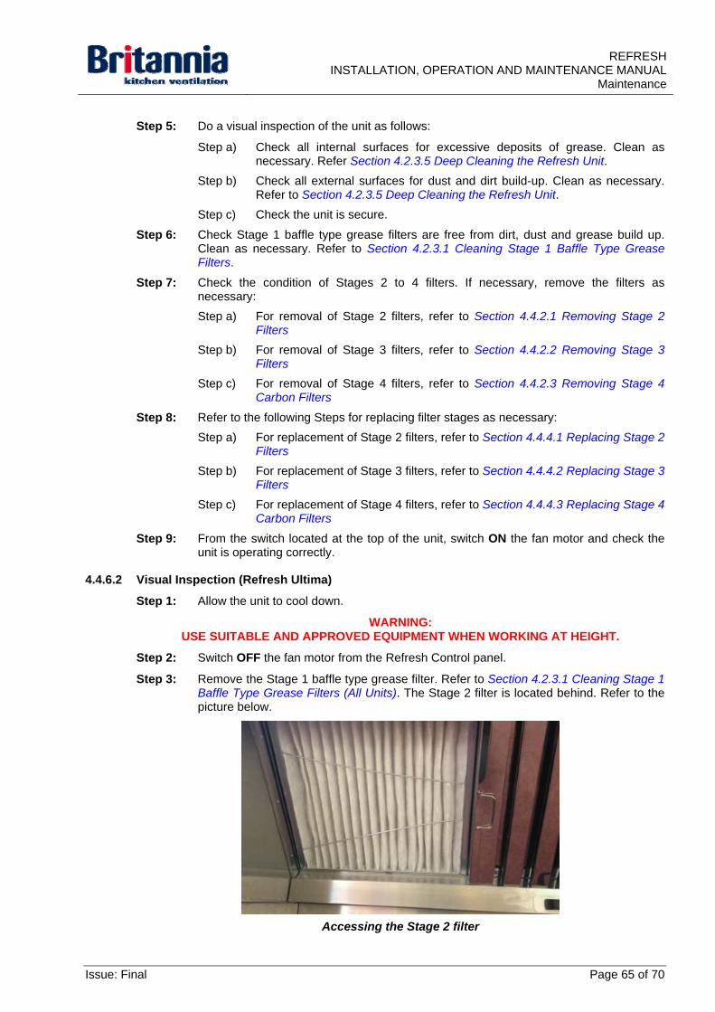
REFRESHINSTALLATION, OPERATION AND MAINTENANCE MANUAL
Maintenance
Step 5: Do a visual inspection of the unit as follows:
Step a) Check all internal surfaces for excessive deposits of grease. Clean as necessary. Refer Section 4.2.3.5 Deep Cleaning the Refresh Unit.
Step b) Check all external surfaces for dust and dirt build-up. Clean as necessary. Refer to Section 4.2.3.5 Deep Cleaning the Refresh Unit.
Step c) Check the unit is secure.
Step 6: Check Stage 1 baffle type grease filters are free from dirt, dust and grease build up. Clean as necessary. Refer to Section 4.2.3.1 Cleaning Stage 1 Baffle Type Grease Filters.
Step 7: Check the condition of Stages 2 to 4 filters. If necessary, remove the filters as necessary:
Step a) For removal of Stage 2 filters, refer to Section 4.4.2.1 Removing Stage 2 Filters
Step b) For removal of Stage 3 filters, refer to Section 4.4.2.2 Removing Stage 3 Filters
Step c) For removal of Stage 4 filters, refer to Section 4.4.2.3 Removing Stage 4 Carbon Filters
Step 8: Refer to the following Steps for replacing filter stages as necessary:
Step a) For replacement of Stage 2 filters, refer to Section 4.4.4.1 Replacing Stage 2 Filters
Step b) For replacement of Stage 3 filters, refer to Section 4.4.4.2 Replacing Stage 3 Filters
Step c) For replacement of Stage 4 filters, refer to Section 4.4.4.3 Replacing Stage 4 Carbon Filters
Step 9: From the switch located at the top of the unit, switch ON the fan motor and check the unit is operating correctly.
4.4.6.2 Visual Inspection (Refresh Ultima)
Step 1: Allow the unit to cool down.
WARNING: USE SUITABLE AND APPROVED EQUIPMENT WHEN WORKING AT HEIGHT.
Step 2: Switch OFF the fan motor from the Refresh Control panel.
Step 3: Remove the Stage 1 baffle type grease filter. Refer to Section 4.2.3.1 Cleaning Stage 1 Baffle Type Grease Filters (All Units). The Stage 2 filter is located behind. Refer to the picture below.
Accessing the Stage 2 filter
Issue: Final Page 65 of 70
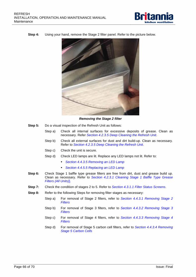
REFRESH INSTALLATION, OPERATION AND MAINTENANCE MANUAL Maintenance
Step 4: Using your hand, remove the Stage 2 filter panel. Refer to the picture below.
Removing the Stage 2 filter
Step 5: Do a visual inspection of the Refresh Unit as follows:
Step a) Check all internal surfaces for excessive deposits of grease. Clean as necessary. Refer Section 4.2.3.5 Deep Cleaning the Refresh Unit.
Step b) Check all external surfaces for dust and dirt build-up. Clean as necessary. Refer to Section 4.2.3.5 Deep Cleaning the Refresh Unit.
Step c) Check the unit is secure.
Step d) Check LED lamps are lit. Replace any LED lamps not lit. Refer to:
Section 4.4.3.5 Removing an LED Lamp
Section 4.4.5.5 Replacing an LED Lamp
Step 6: Check Stage 1 baffle type grease filters are free from dirt, dust and grease build up. Clean as necessary. Refer to Section 4.2.3.1 Cleaning Stage 1 Baffle Type Grease Filters (All Units)].
Step 7: Check the condition of stages 2 to 5. Refer to Section 4.3.1.1 Filter Status Screens.
Step 8: Refer to the following Steps for removing filter stages as necessary:
Step a) For removal of Stage 2 filters, refer to Section 4.4.3.1 Removing Stage 2 Filters
Step b) For removal of Stage 3 filters, refer to Section 4.4.3.2 Removing Stage 3 Filters
Step c) For removal of Stage 4 filters, refer to Section 4.4.3.3 Removing Stage 4 Filters
Step d) For removal of Stage 5 carbon cell filters, refer to Section 4.4.3.4 Removing Stage 5 Carbon Cells
Page 66 of 70 Issue: Final
REFRESHINSTALLATION, OPERATION AND MAINTENANCE MANUAL
Maintenance
Step 9: Refer to the following Steps for replacing filter stages as necessary:
Step a) For replacement of Stage 2 filters, refer to Section 4.4.5.1 Replacing Stage 2 Filters
Step b) For replacement of Stage 3 filters, refer to Section 4.4.5.2 Replacing Stage 3 Filters
Step c) For replacement of Stage 4 filters, refer to Section 4.4.5.3 Replacing Stage 4 Filters
Step d) For replacement of Stage 5 carbon cell filters, refer to Section 4.4.5.4 Replacing Stage 5 Carbon Cells
Step 10: Reset the filter operational hours. Refer to Section 3.3 Resetting the Filter Operational Hours.
Step 11: From the Refresh Control Panel, switch ON the fan motor Check the unit is operating correctly.
Issue: Final Page 67 of 70
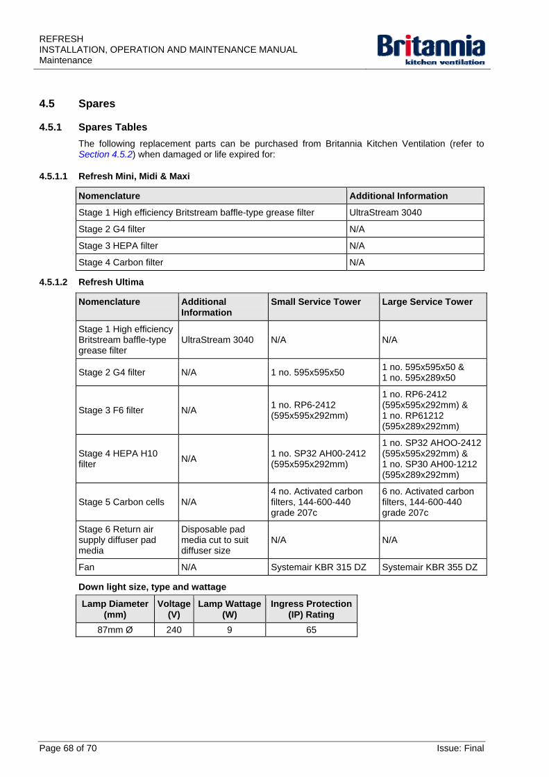
REFRESH INSTALLATION, OPERATION AND MAINTENANCE MANUAL Maintenance
4.5 Spares
4.5.1 Spares Tables
The following replacement parts can be purchased from Britannia Kitchen Ventilation (refer to Section 4.5.2) when damaged or life expired for:
4.5.1.1 Refresh Mini, Midi & Maxi
Nomenclature Additional Information
Stage 1 High efficiency Britstream baffle-type grease filter UltraStream 3040
Stage 2 G4 filter N/A
Stage 3 HEPA filter N/A
Stage 4 Carbon filter N/A
4.5.1.2 Refresh Ultima
Nomenclature Additional Information
Small Service Tower Large Service Tower
Stage 1 High efficiency Britstream baffle-type grease filter
UltraStream 3040 N/A N/A
Stage 2 G4 filter N/A 1 no. 595x595x50 1 no. 595x595x50 & 1 no. 595x289x50
Stage 3 F6 filter N/A 1 no. RP6-2412 (595x595x292mm)
1 no. RP6-2412 (595x595x292mm) & 1 no. RP61212 (595x289x292mm)
Stage 4 HEPA H10 filter
N/A 1 no. SP32 AH00-2412 (595x595x292mm)
1 no. SP32 AHOO-2412 (595x595x292mm) & 1 no. SP30 AH00-1212 (595x289x292mm)
Stage 5 Carbon cells N/A 4 no. Activated carbon filters, 144-600-440 grade 207c
6 no. Activated carbon filters, 144-600-440 grade 207c
Stage 6 Return air supply diffuser pad media
Disposable pad media cut to suit diffuser size
N/A N/A
Fan N/A Systemair KBR 315 DZ Systemair KBR 355 DZ
Down light size, type and wattage
Lamp Diameter (mm)
Voltage (V)
Lamp Wattage (W)
Ingress Protection (IP) Rating
87mm Ø 240 9 65
Page 68 of 70 Issue: Final
REFRESHINSTALLATION, OPERATION AND MAINTENANCE MANUAL
Maintenance
4.5.2 Ordering Information
Contact Britannia Kitchen Ventilation for pricing and availability of spare parts. Refer to the contact details below:
Britannia Kitchen Ventilation Ltd 10 Highdown Road Sydenham Industrial Estate Leamington Spa Warwickshire CV31 1XT England
Phone 01926-463540 Fax 01926-463541 Email sales@kitchen ventilation.co.uk Web www.kitchen-ventilation.co.uk
Use of components or replacement parts other than those supplied or recommended by Britannia Kitchen Ventilation Ltd will invalidate any warranties or guarantees.
Issue: Final Page 69 of 70
REFRESH INSTALLATION, OPERATION AND MAINTENANCE MANUAL Maintenance
Page 70 of 70 Issue: Final
4.6 GA Diagrams
4.6.1 Refresh Mini, Midi & Maxi
Drawing No. Drawing Title Revision
None Exploded View (Midi) -
4.6.2 Refresh Ultima
Drawing No. Drawing Title Revision
TESP-BRIT-CS-RF01 New Refresh - Kitchen Ventilation Recirc - Canopy Wiring Diagram
-
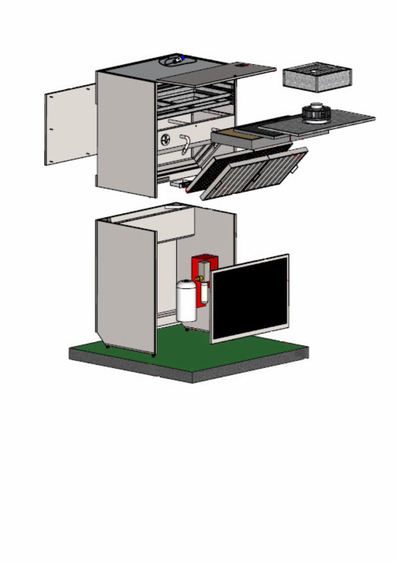
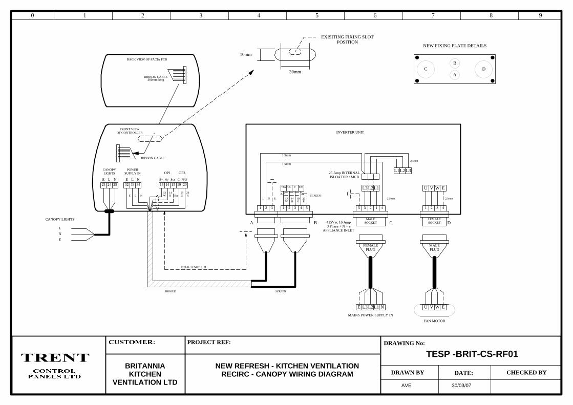
0 1 2 3 4 5 6 7 8 9
PROJECT REF:
DRAWN BY
DRAWING No:
DATE: CHECKED BYNEW REFRESH - KITCHEN VENTILATION
RECIRC - CANOPY WIRING DIAGRAMBRITANNIAKITCHEN
VENTILATION LTD
TESP -BRIT-CS-RF01
AVE 30/03/07
L1L2L3
L1 L2 L3
U V W E
U V W E
415Vac 16 Amp3 Phase + N + e
APPLIANCE INLET
25 Amp INTERNALISLOATOR / MCB
FEMALESOCKET
MALEPLUG
FEMALEPLUG
MALESOCKET
FAN MOTOR
L
N
E
343332E L N
POWERSUPPLY IN
13 14 15 19 20
S+ 0v Scr C N/O
OP1 OP3
252423E L N
CANOPYLIGHTS
NL1L2L3E
BACK VIEW OF FACIA PCB
RIBBON CABLE
RIBBON CABLE
FRONT VIEWOF CONTROLLER
MAINS POWER SUPPLY IN
1 2 3 1 2 3 4 5 123 45 1 2 3 4
G RBW ScrE L N
VIA CC F P24
13 14 19 20EL N
CANOPY LIGHTS
INVERTER UNIT
13 14 19 20
SCREENSHROUD
TOTAL LENGTH 1M
10mm
30mm
EXISITING FIXING SLOTPOSITION
A B C D
C DA
B
NEW FIXING PLATE DETAILS
1.5mm
1.5mm
SCREEN
BW G R2.5mm 2.5mm
2.5mm
300mm long