refrigerator rmdx installation instructionsl-1 of symbols!! a i note you can find details on the...
TRANSCRIPT
Absorber refrigeratorInstallation ManualEN
RMDX21, RMDX25

RMDX21, RMDX25
2
622 mm525 mm
1245
mm
550 mm
1264
mm
BA1
2 3
4
1
2

RMDX21, RMDX25
3
≥ 12
50
< 12
50
13
10 - 40>40 >40
4
RMDX21, RMDX25
4
≥ 14
00
10 - 40
1
5
≥ 3001 2
6

RMDX21, RMDX25
5
≥ 40 mm
8
1
7
3
2
1
9
0 a

RMDX21, RMDX25
6
1.
2.3.
b
1
2
c d
e f

RMDX21, RMDX25
7
10
1
97
8
66
4
5
3
2
g
1.
2.
h
min. 15 mm
1.
2.
3.
i
RMDX21, RMDX25
8
j
12
k
l 507,5
907,
4
≤ 1,7
≤ 1,7
≤ 1,7
507,5
99,5
300
36
99,5
507,5
300
36
A B
RMDX21, RMDX25
9
1.
2.
3.
4.
m

RMDX21, RMDX25
10
4. 3.2.
1.
n
RMDX21, RMDX25
11
1.
2.
3.
o

RMDX21, RMDX25
12
3.
1.
2.
p
q

RMDX21, RMDX25
13
2.
3.
1.
r
s
RMDX21, RMDX25
14
INO
UT
LL
NN AC
TO G
V 12VDC
OU
T
TO FC
TOP
ABS
HE OUT 12 VDC HE IN
swrtbrbrbrwsws wsS+D+
D+
(+)vtsw
rt/vt
rt
(+)
(+) (+)
(+)(-)
(-)(-)
(-) (+) (-)
LNL
A
B C D E
G
F
12
6
5
4
8
7
9
16
10
3
12
1311
N
14
15
t
RMDX21, RMDX25
15
Item Description
1 Heating cartridge AC power
2 AC power connection cable
3 Earth AC power
4 Ionisation
5 Ignition
6 Burner
7 Heating cartridge DC power supply
8 Heating cartridge DC power
9 LED lighting
10 Electronics DC power supply
11 Gas inlet
12 Gas outlet
13 Gas valve
14 DC power outlet
15 Gas valve supply line
16 Switch-off fuse (overheating protection)
A Optional connections to DC power outlet
B Negative terminal (–) DC permanent supply for electronics
C Positive terminal (–) DC permanent supply for electronics
D Connection D+
E Heating element positive terminal (+) DC power
F Heating element earth terminal DC power
G Connection S+
br brown
rt red
sw black
ws white

RMDX21, RMDX25
16
u
+ - + -
House Battery
Anderson PlugAnderson cables must be therecommended size.
AESRefrigerator DC connections
D+ Control Element DCD C B E F
v
+ - + -
Vehicle Anderson plug mustbe controlled by ignition relay.
House Battery
Anderson PlugAnderson cables must be therecommended size.
AESRefrigerator DC connections
D+ Control Element DCD C B E F
w

RMDX21, RMDX25
17
+ - + -
FridgeSwitch
Vehicle Anderson plug mustbe controlled by ignition relay.
House Battery
Anderson PlugAnderson cables must be therecommended size.
AESRefrigerator DC connections
D+ Control Element DCD C B E F
x
+ - + -
FridgeSwitch
Vehicle Anderson plug mustbe controlled by ignition relay.
House Battery
Anderson PlugAnderson cables must be therecommended size.
AESRefrigerator DC connections
D+ Control Element DCD C B E F
y
+ - + -
Vehicle Anderson plug mustbe controlled by ignition relay.
House Battery
Anderson PlugAnderson cables must be therecommended size.
AESRefrigerator DC connections
D+ Control Element DCD C B E F
z

EN
Explanation of symbols RMDX21, RMDX25
18
Please read this instruction manual carefully before installation and first use, and store it in a safe place. If you pass on the product to another person, hand over this instruction manual along with it.
ITable of contents
1 Explanation of symbols . . . . . . . . . . . . . . . . . . . . . . . . . . . . . . . . . . 18
2 Safety instructions . . . . . . . . . . . . . . . . . . . . . . . . . . . . . . . . . . . . . . 19
3 Scope of delivery . . . . . . . . . . . . . . . . . . . . . . . . . . . . . . . . . . . . . . . 21
4 Accessories . . . . . . . . . . . . . . . . . . . . . . . . . . . . . . . . . . . . . . . . . . . 21
5 Intended use . . . . . . . . . . . . . . . . . . . . . . . . . . . . . . . . . . . . . . . . . . 21
6 Installing the refrigerator . . . . . . . . . . . . . . . . . . . . . . . . . . . . . . . . . 22
7 Connecting the refrigerator . . . . . . . . . . . . . . . . . . . . . . . . . . . . . . . 30
8 Technical data . . . . . . . . . . . . . . . . . . . . . . . . . . . . . . . . . . . . . . . . . 35
1 Explanation of symbols
!
!
A
I
NOTE You can find details on the operation in the operation manual.
WARNING! Safety instruction: Failure to observe this instruction can cause fatal or serious injury.
CAUTION! Safety instruction: Failure to observe this instruction can lead to injury.
NOTICE! Failure to observe this instruction can cause material damage and impair the function of the product.
NOTE Supplementary information for operating the product.

EN
RMDX21, RMDX25 Safety instructions
19
2 Safety instructionsThe manufacturer accepts no liability for damage in the following cases:z Faulty assembly or connectionz Damage to the product resulting from mechanical influences and excess
voltagez Alterations to the product without express permission from the manu-
facturerz Use for purposes other than those described in the operating manual
!WARNING! z Never open the absorber unit. It is under high pressure and can
cause injury if it is opened.z Ensure clean and residue-free handling if silicon sealant or
similar is used. There is a risk of fire if silicone filaments come into contact with hot parts or naked flames.
z Do not operate the refrigerator if it is visibly damaged.z If the AC power cable for this refrigerator is damaged, it must be
replaced by the manufacturer, customer service or a similarly qualified person in order to prevent safety hazards.
z Never use a naked flame to check the refrigerator for leaks.z This refrigerator may only be repaired by qualified personnel.
Inadequate repairs may cause serious hazards.z Only use universal LPG gas.z Only operate the refrigerator at the pressure shown on the
type plate. Only use pressure controllers with a fixed setting which comply with national regulations.
z Dismantle all refrigerator doors for the disposal of the old refrigerator and leave the shelves in the refrigerator to prevent accidental enclosure and suffocation.
!CAUTION! z Danger of crushing! Do not put your fingers into the hinge.z Before starting the device, ensure that the power supply line
and the plug are dry.

EN
Safety instructions RMDX21, RMDX25
20
ANOTICE! z Only hold the refrigerator at the body of the refrigerator during
transport. Never hold the refrigerator at the absorber unit, the cooling fins, the gas pipes, the door or the control panel.
z Make sure that the refrigerator circuit is not damaged during transportation. The refrigerant in the refrigerator circuit is highly flammable.In the event of any damage to the refrigerator circuit (smell of ammonia):– Switch off the refrigerator if applicable.– Avoid naked flames and sparks.– Air the room well.
z Do not install the refrigerator near naked flames or other heat sources (heaters, direct sunlight, gas ovens etc.).
z Danger of overheating!Always ensure sufficient ventilation so that the heat generated during operation can dissipate. Make sure that the refrigerator is sufficiently far away from walls and other objects so that the air can circulate.
z Check that the voltage specification on the type plate is the same as that of the power supply.
z Do not open the refrigerant circuit under any circumstances.z Only use the AC connection cable supplied to connect the
refrigerator to the AC mains.z Only use cables with a suitable size.z Never pull the plug out of the socket by the connection cable.z The refrigerator may not be exposed to rain.
EN
RMDX21, RMDX25 Scope of delivery
21
3 Scope of deliveryz Refrigeratorz Ice-cube trayz Operating manualz Installation manual
4 AccessoriesAvailable as accessories (not included in the scope of delivery):
All the accessories are available from specialist dealers. If you have any questions, please contact the dealer or your service partner directly.
5 Intended useThe refrigerators RMDX21 and RMDX25 are designed for installation in caravans or motorhomes. They are only suitable for cooling and storing food-stuffs. The refrigerators are not intended for the proper storage of medicine.
The refrigerators are designed to be operated on a DC power supply, AC mains power supply or universal LPG gas.
Description
LS300 ventilation grille
3776 gas exhaust vent

EN
Installing the refrigerator RMDX21, RMDX25
22
6 Installing the refrigerator
6.1 Preparing the installationWhen installing the refrigerator, note the following:z To enable the refrigerant to circulate properly, the refrigerator may not
exceed an angle of 3° from level.To achieve this, park the vehicle on a level firm surface. Ensure the refrigerator is level.
z The refrigerator must be installed so that it is easily accessible for service work, easy to de-install and install and can be easily removed from the vehicle.
z The refrigerator must be installed in a recess so that it stands secure when the vehicle is in motion. Note the following recess dimensions are (H x W x D in mm): – Recess without flange: 1249 x 527 x 572 (fig. 1 A, page 2)– Recess with flange: 1252 x 530 x 572 (fig. 1 B, page 2)
z The outer wall must be fitted with an air inlet vent (fig. 2 1, page 2) and an outlet vent (fig. 2 2, page 2) with ventilation grilles so that the heat generated can be easily released to the outside:– Lower air inlet vent LS300 must be installed as flush as possible to the
vehicle floor. Air inlet vent must have a minimum of 400 cm2 open area.
– Upper air outlet vent LS300 must be installed with the bottom of the vent no lower than equal to the top of the refrigerator cabinet, the bot-tom of the top vent can be higher than the cabinet.
z Fit a heat conduction plate (fig. 2 3, page 2) above the refrigerator so that the heat does not accumulate in the vehicle.
z If the lower ventilation grille of the air inlet vent cannot be installed flush to the floor, an additional inlet vent (fig. 2 4, page 2) must be provided in the floor for releasing any possible gas leakage.
z The distance between the refrigerator and the rear wall must be at least 10 mm.
z A distance of more than 40 mm between the refrigerator and rear wall leads to poor performance and increases the power consumption of the refrigerator. Reduce the space behind the refrigerator to create adequate air inlet and outlet ventilation corridor (fig. 4, page 3). Use a ventilation plate, for example, to do this.
EN
RMDX21, RMDX25 Installing the refrigerator
23
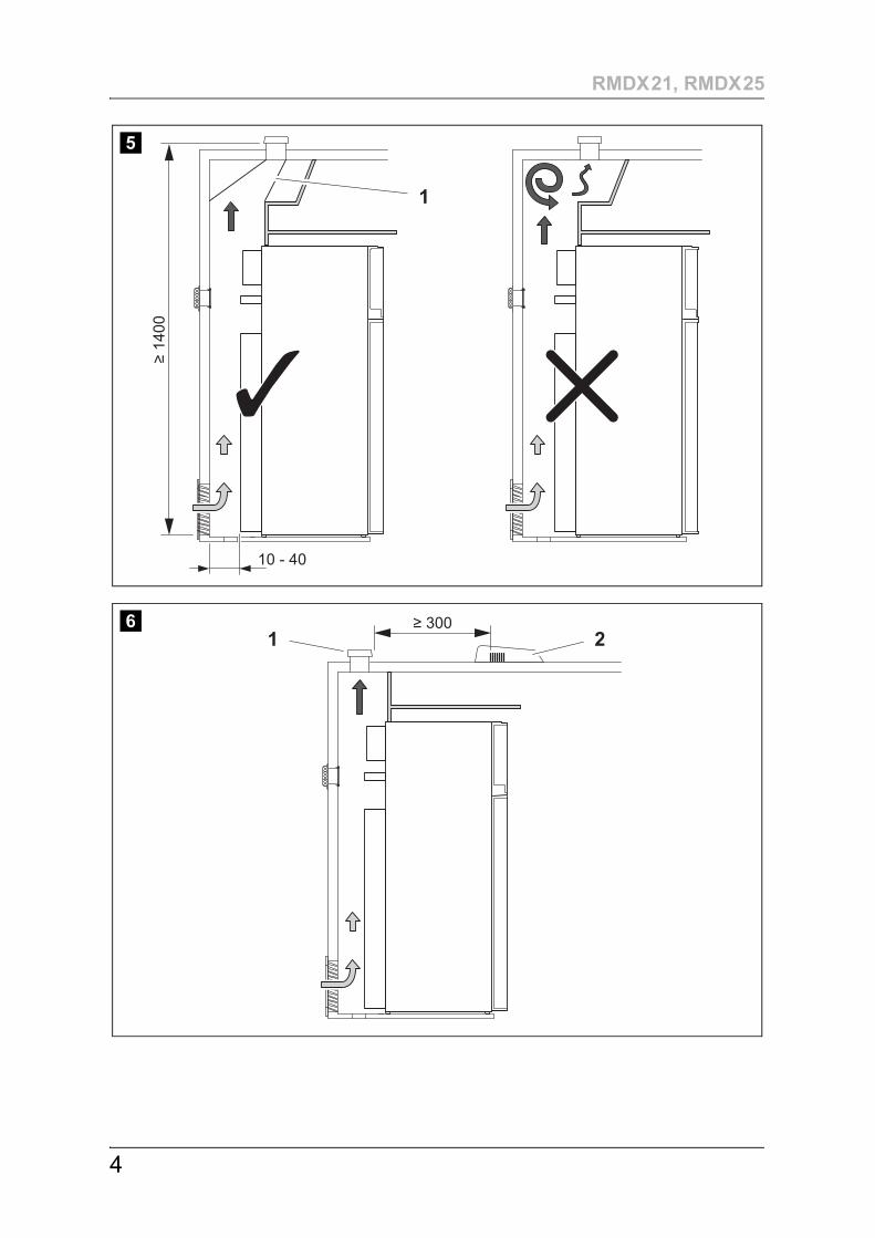
z If the minimum distance between the air inlet and outlet vents cannot be met, a roof vent must be installed instead of the air outlet vent.– The roof vent should be installed directly above the back of the
refrigerator as far as this is possible. Use an air duct (fig. 5 1, page 4) if you need to install the roof vent offset, otherwise heat will accumu-late there.
– The distance between the air inlet vent and the roof vent must be at least 1400 mm (fig. 5, page 4).
– If a roof air conditioner is provided, the distance between the roof vent (fig. 6 1, page 4) and the air outlet of the roof air conditioner (fig. 6 2, page 4) must be at least 300 mm.
z The refrigerator must not be installed at the side of the air inlet and outlet vents as this leads to poor performance and increases the power consumption of the refrigerator.
z The air inlet and outlet vents must not be covered by vehicle parts (such as an open door or by installing accessories such as bicycle racks) while operating.
z A separate flue duct must be installed under the air outlet vent, see chap-ter “Installing the flue duct” on page 27.
z Install the refrigerator so that it is protected from excessive heat, as this leads to poor performance and increases the power consumption of the refrigerator.
z The electrical installation must comply with national and local regulations.z The gas installation must comply with national and local regulations.
AS 5601.2 – Gas InstallationsNZ 5601 – Gas Appliance Safety
z The refrigerator must be installed in a draught-proof location, see chapter “Installing the refrigerator in a sealed location separate to the living space” on page 24.
EN
Installing the refrigerator RMDX21, RMDX25
24
6.2 Installing the refrigerator in a sealed location separate to the living space
Gas-powered refrigerators in caravans or motorhomes must be installed in a sealed location. This means that the combustion air can not be extracted from the interior and exhaust fumes are prevented from directly entering the living space.
A suitable seal must be provided and fitted between the rear wall of the refrigerator cabinet and the interior of the vehicle. The purpose is to provide a seal between the interior of the vehicle and the cooling unit and ventilation area behind the refrigerator.
!The manufacturer recommends using a flexible seal to ease removal and installation for maintenance purposes.
➤ Attach the sealing lips (fig. 7 1, page 5) to a stop rail behind the refrigerator, for example, by using an adhesive.
➤ When installing, push the refrigerator against the stop rails with the sealing lips. This then seals the space behind the refrigerator to the interior of the vehicle.
WARNING! Fire hazard!Do not use flammable materials such as silicone sealants, foam or similar for the draught-proof installation.
EN
RMDX21, RMDX25 Installing the refrigerator
25
6.3 Making air inlet and outlet vents
I➤ Make a cut out in the wall to fit an appropriate upper and lower vent
system, choose LS300 check the dimensions required for the vent. See chapter “Preparing the installation” on page 22.
If the lower ventilation grille cannot be installed flush with the floor, you will need to provide a vent hole though the floor. This hole must be at lest 40 mm diameter or larger:
➤ Make an air inlet vent in the floor (fig. 2 4, page 2) behind the refrigerator near the gas burner.
➤ Shield the end of the opening with a deflector to prevent sludge or dirt from getting inside while driving (fig. 8, page 5).
If you have to use a roof vent instead of an upper wall vent:
➤ Cut out a section in the roof. Refer to the roof vent instruction manual for the required dimensions. When doing so, observe the information, see chapter “Preparing the installation” on page 22.
NOTE At high ambient temperatures, the refrigerator can only provide its maximum cooling capacity if the optimum ventilation has been provided.
EN
Installing the refrigerator RMDX21, RMDX25
26
6.4 Installing the ventilation grille
➤ Ensure the installation frame is water resistant (fig. 0, page 5).
➤ Insert the installation frame and screw it down tightly (fig. a, page 5). Use all the fixing holes for this.
➤ Fit the ventilation grille (fig. b, page 6).
➤ Insert the slider and lock the ventilation grille with it (fig. b, page 6).
6.5 Install the roof vent
➤ Ensure the installation frame is water resistant (fig. d, page 6).
➤ Insert the installation frame and screw it down tightly (fig. e, page 6). Use all the fixing holes for this.
➤ Insert the hood and screw it down tightly (fig. f, page 6).
No. in fig. 9, page 5 Description
1 Slider
2 Ventilation grille
3 Installation frame
No. in fig. c, page 6 Description
1 Hood
2 Installation frame
EN
RMDX21, RMDX25 Installing the refrigerator
27
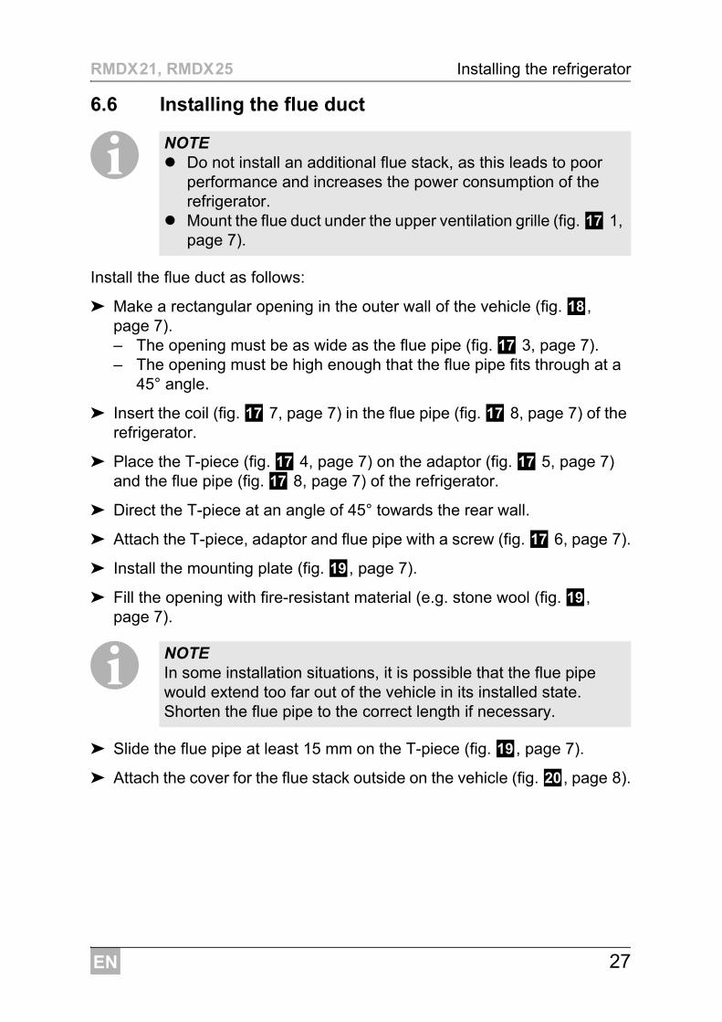
6.6 Installing the flue duct
I
Install the flue duct as follows:
➤ Make a rectangular opening in the outer wall of the vehicle (fig. h, page 7).– The opening must be as wide as the flue pipe (fig. g 3, page 7).– The opening must be high enough that the flue pipe fits through at a
45° angle.
➤ Insert the coil (fig. g 7, page 7) in the flue pipe (fig. g 8, page 7) of the refrigerator.
➤ Place the T-piece (fig. g 4, page 7) on the adaptor (fig. g 5, page 7) and the flue pipe (fig. g 8, page 7) of the refrigerator.
➤ Direct the T-piece at an angle of 45° towards the rear wall.
➤ Attach the T-piece, adaptor and flue pipe with a screw (fig. g 6, page 7).
➤ Install the mounting plate (fig. i, page 7).
➤ Fill the opening with fire-resistant material (e.g. stone wool (fig. i, page 7).
I➤ Slide the flue pipe at least 15 mm on the T-piece (fig. i, page 7).
➤ Attach the cover for the flue stack outside on the vehicle (fig. j, page 8).
NOTE z Do not install an additional flue stack, as this leads to poor
performance and increases the power consumption of the refrigerator.
z Mount the flue duct under the upper ventilation grille (fig. g 1, page 7).
NOTE In some installation situations, it is possible that the flue pipe would extend too far out of the vehicle in its installed state. Shorten the flue pipe to the correct length if necessary.

EN
Installing the refrigerator RMDX21, RMDX25
28
6.7 Securing the refrigerator
!
I➤ Move the refrigerator into its final location.
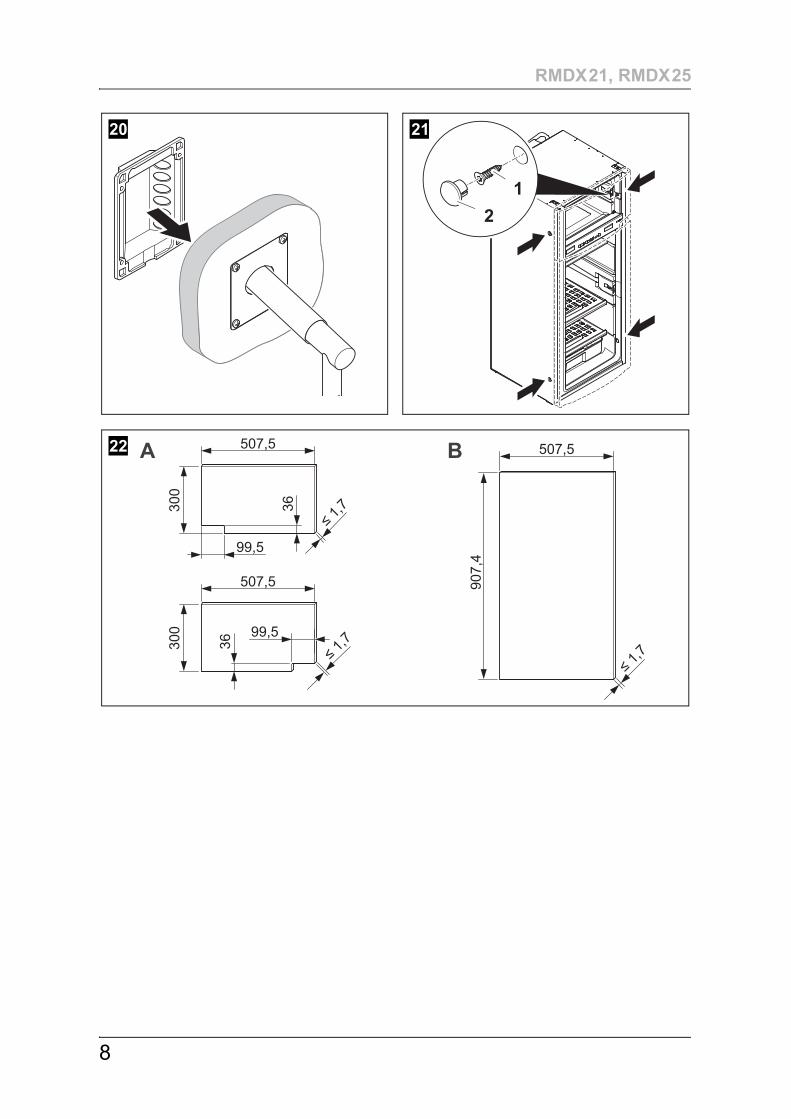
➤ Fasten the four screws (fig. k 1, page 8) through the four plastic washers in the sides of the refrigerator, and further into the wall.
➤ Put the caps (fig. k 2, page 8) onto the screw heads.
6.8 Replacing the door panel
AOnly decorative trim with frame: The door panel has the following dimensions (fig. l, page 8):z Freezer compartment door: Az Refrigerator door: B
Removing the door panel from framed door model
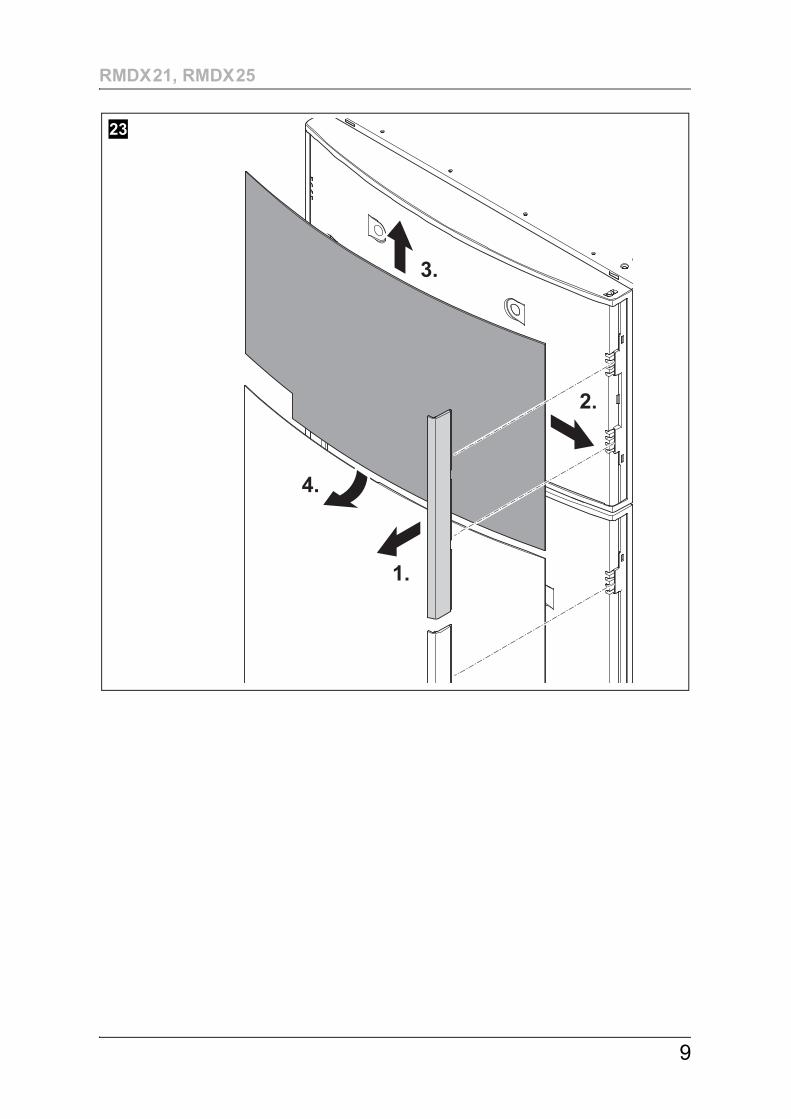
Proceed as follows (fig. m, page 9):
➤ Remove the door trim carefully. It is only clipped in and held in place by small hooks.
➤ Pull the old panel away from the door trim still installed.
➤ Push the old panel upwards as far as the stop.
➤ Pull the old panel out of the door.
CAUTION! Only screw through the receptacles provided, otherwise foamed components, including cables, can be damaged.
NOTE Attach the side walls or the attached strips so that the screws are tight, even when under increased loads (while driving).
NOTICE! Beware of damageThe door panel must not be replaced when the refrigerator is upright.
EN
RMDX21, RMDX25 Installing the refrigerator
29
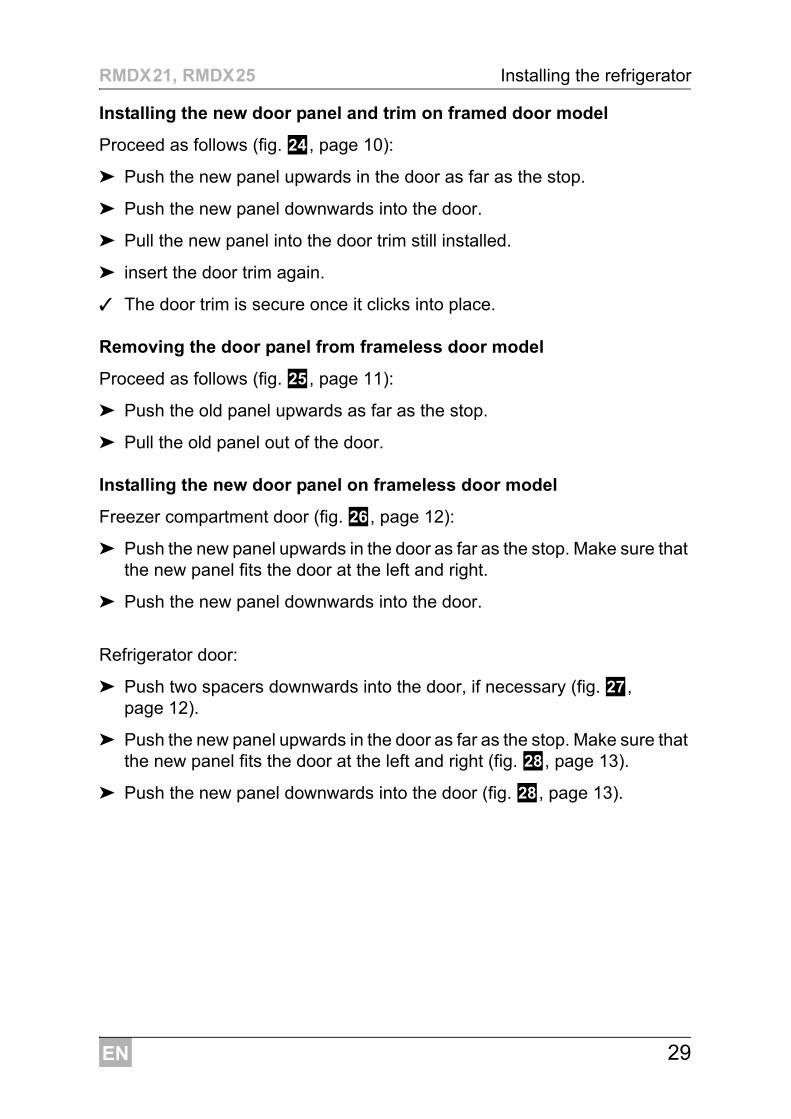
Installing the new door panel and trim on framed door model
Proceed as follows (fig. n, page 10):
➤ Push the new panel upwards in the door as far as the stop.
➤ Push the new panel downwards into the door.
➤ Pull the new panel into the door trim still installed.
➤ insert the door trim again.
✓ The door trim is secure once it clicks into place.
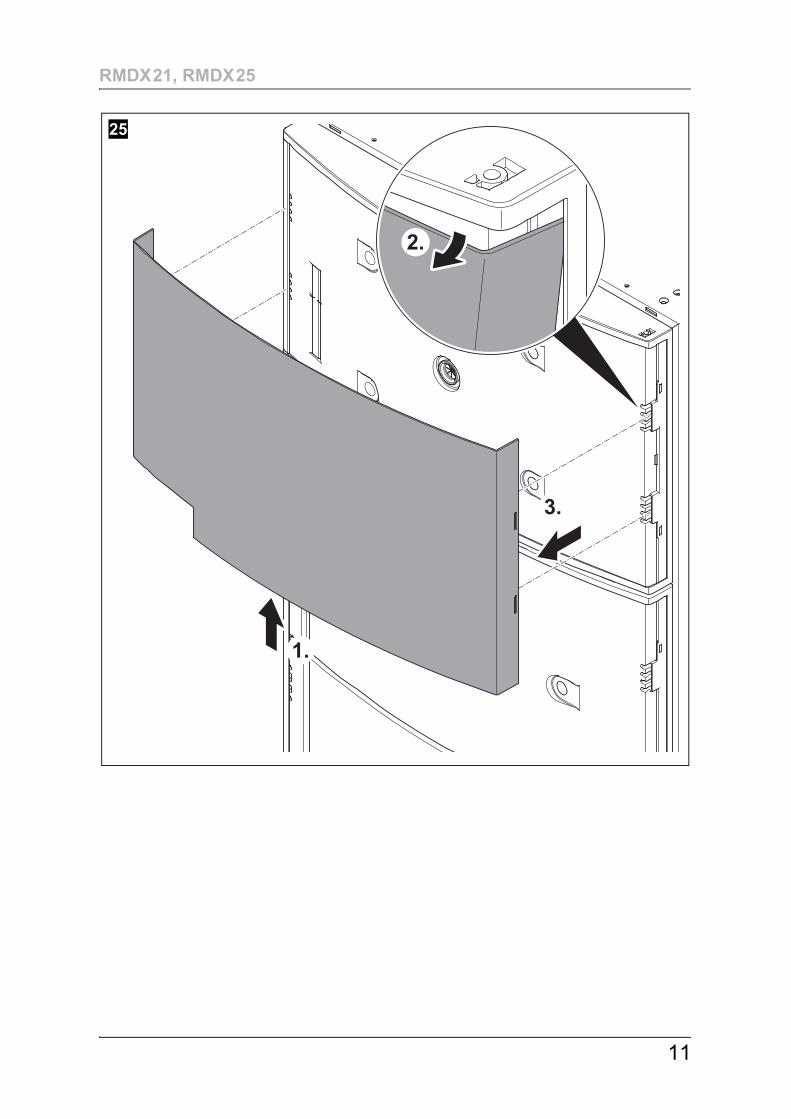
Removing the door panel from frameless door model
Proceed as follows (fig. o, page 11):
➤ Push the old panel upwards as far as the stop.
➤ Pull the old panel out of the door.
Installing the new door panel on frameless door model
Freezer compartment door (fig. p, page 12):
➤ Push the new panel upwards in the door as far as the stop. Make sure that the new panel fits the door at the left and right.
➤ Push the new panel downwards into the door.
Refrigerator door:
➤ Push two spacers downwards into the door, if necessary (fig. q, page 12).
➤ Push the new panel upwards in the door as far as the stop. Make sure that the new panel fits the door at the left and right (fig. r, page 13).
➤ Push the new panel downwards into the door (fig. r, page 13).
EN
Connecting the refrigerator RMDX21, RMDX25
30
7 Connecting the refrigerator
7.1 Connecting to the gas supply
A
IIt must be possible to shut off the refrigerator from the gas line separately by means of a shut-off device. The shut-off device must be easily accessible.
➤ Connect the refrigerator securely to the gas supply (fig. s, page 13).
➤ Have a leak test and a flame test performed by an authorised specialist after professional installation.Ensure you are issued with a certificate of inspection.
NOTICE! z This refrigerator may only be connected to the gas supply by
a specialist in accordance with the applicable guidelines and standards.
z Only use cylinders of universal LPG gas fitted with an approved gas pressure regulator. Compare the pressure infor-mation on the data plate with the pressure information on the pressure regulator on the gas cylinder.
z Only operate the refrigerator at the pressure shown on the data plate.
z Only operate the refrigerator with the type of gas shown on the data plate.
z Please note the pressures which are permitted in your country. Only use pressure controllers with a fixed setting which comply with the national regulations.
NOTE The refrigerator is equipped for a connection pressure of 2.75 kPa.

EN
RMDX21, RMDX25 Connecting the refrigerator
31
7.2 Connecting to DC and AC
A
I
NOTICE! z The electrical installation and repairs may only be performed
by a specialist in accordance with the applicable regulations and standards.
z The respective negative and positive cables of the DC connections for heating and controls may not be joined with one another in a caravan. This can cause electrical interference or damage to electrical components.
z DC connection to the heating element must be made to the vehicle engine battery, connection only while engine is running. See fig. u, page 16
NOTE z The mains socket must be easily accessible so that you can
unplug the power cord if required, thereby disconnecting the refrigerator from the power.
z The plug of the AC connection cable must not be cut off.z The connection cables must be laid so that they do not come
in contact with hot parts of the unit/burner or with sharp edges.z Changes to the internal electrical installation or the connection
of other electrical components (e.g. extra third party fans) to the internal wiring of the refrigerator will void any claims from the guarantee and product liability.

EN
Connecting the refrigerator RMDX21, RMDX25
32
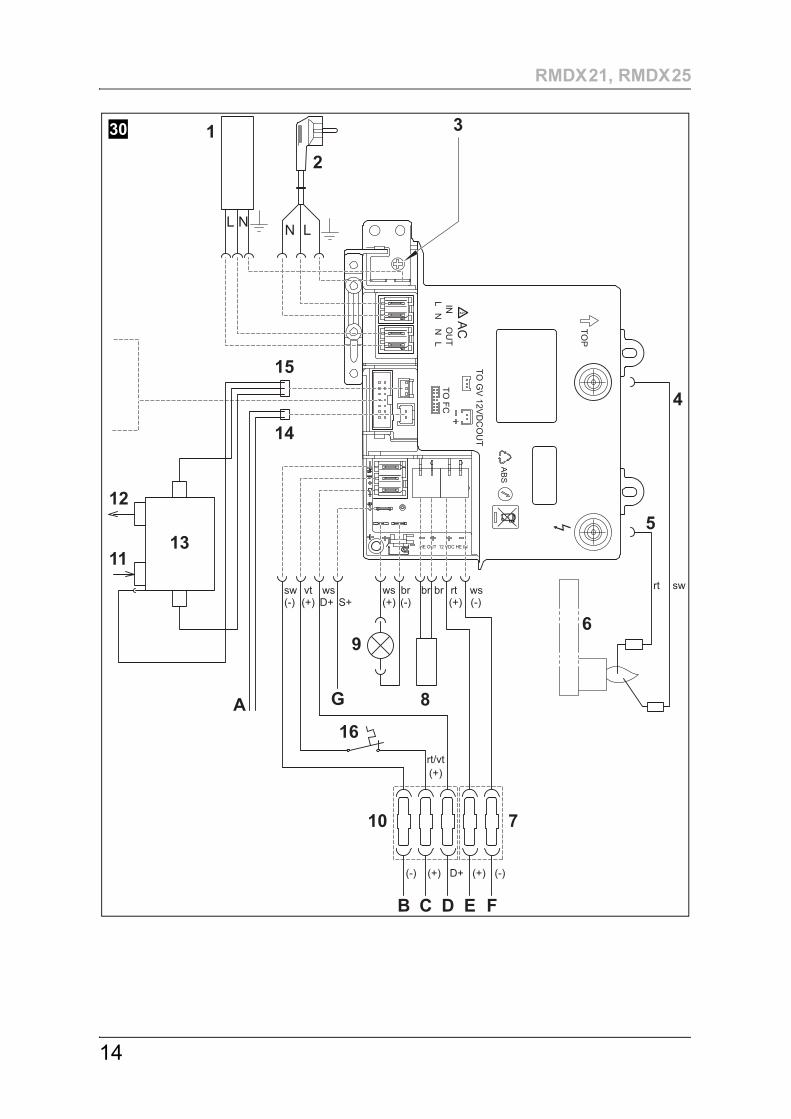
➤ Connect the refrigerator as follows (fig. t, page 14):
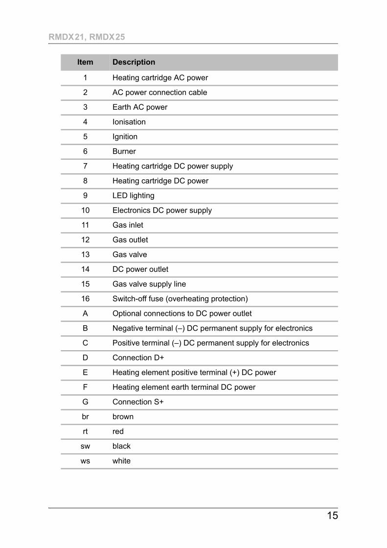
Item Description
1 Heating cartridge AC power
2 AC power connection cable
3 Earth AC power
4 Ionisation
5 Ignition
6 Burner
7 Heating cartridge DC power supply
8 Heating cartridge DC power
9 LED lighting
10 Electronics DC power supply
11 Gas inlet
12 Gas outlet
13 Gas valve
14 DC power outlet
15 Gas valve supply line
16 Switch-off fuse (overheating protection)
A Optional connections to DC power outlet
B Negative terminal (–) DC permanent supply for electronics
C Positive terminal (–) DC permanent supply for electronics
D Connection D+
E Heating element positive terminal (+) DC power
F Heating element earth terminal DC power
G Connection S+

EN
RMDX21, RMDX25 Connecting the refrigerator
33
AC power
➤ Connect the refrigerator with the mains plug to an AC socket.
DC power
Please note the following cable sizes:– < 6 m (interior): 6 mm2
– > 6 m (interior): 10 mm2
– Connections D+ and S+: 1 mm2
➤ Protect the DC power supply for heater with 20 A fuse and use a minimum of 6 mm low voltage cable.
➤ Protect the DC power supply for controls with 2 A fuse and use a minimum of 1 mm low voltage cable.
➤ Run cables to the heating element via a relay or suitable means controlled by an ignition switch to prevent battery from completely discharging, if the engine is switched off (fig. u, page 16).
➤ Connect DC positive heater cable to terminal (fig. t E, page 14).
➤ Connect DC negative heater cable to terminal (fig. t F, page 14).
➤ Connect continuous 12 Vg positive supply to terminal (fig. t C, page 14).
➤ Connect continuous 12 Vg negative supply to terminal (fig. t B, page 14).
D+ (RMDX25 only)
In automatic mode, the refrigerator selects the most favourable mode available. The refrigerator is only operated with direct current when the vehicle engine is running. The electronics of the refrigerator uses the signal D+ from the light system to detect the running engine.
➤ Connect the D+ connection to the controls (fig. t D, page 14) with the respective terminal of the vehicle.

EN
Connecting the refrigerator RMDX21, RMDX25
34
S+ (RMDX25 only)
In automatic mode, the refrigerator is first powered with DC power from the vehicle's own solar system. The refrigerator electronics uses the S+ signal of the solar charge controller to detect a solar system. The solar charge controller must have an AES output and produce sufficient current to run the refrigerator.
➤ Connect the S+ connection on the controller (fig. t G, page 14) to the respective terminal of the solar charge controller.
Suitable solar charge controllers are available from specialist dealers.The manufacturer recommends, for example:z Büttner MT 300-S
(www.buettner-elektronik.de)z Votronic MPP 240 Duo Digital
(www.votronic.de)
7.3 Connecting an AES refrigerator (optional)
See fig. v, page 16
Connection to suit motor home or caravan with the D+ wire connected to the vehicle alternator or ignition switch.
No house battery recharging from the vehicle.
The D+ connection is taken to the vehicle alternator.
See fig. w, page 16
Anderson plug controlled by vehicle relay to the ignition switch. Power can only be supplied if the engine is running.
No house battery recharging from the vehicle.
See fig. x, page 17
Using a fridge movement switch to add 12 Vg to the D+ connection wire, only when the vehicle is moving.
No house battery recharging from the vehicle.
The D+ is turned on and off via an optional fridge movement switch.

EN
RMDX21, RMDX25 Technical data
35
See fig. y, page 17
Using a fridge movement switch to add 12 Vg to the D+ connection wire, only when the vehicle is moving. The Anderson plug connection must keep the house battery fully charged.
House battery recharged by vehicle.
The D+ is turned on and off via an optional fridge movement switch.
See fig. z, page 17
Anderson plug recharging the house battery via a power diode. The D+ wire can only get a 12 V signal when the battery is being charged.
House battery recharged by vehicle.
The D+ is turned on and off by the vehicle starting and stopping.
8 Technical dataRMDX21, RMDX25
Voltage: 230 Vw / 50 Hz12 Vg
Capacity – total:Capacity – freezer compartment:
190 l30 l
Power consumption: 250 W (230 Vw)170 W (12 Vg)
Power consumption: 4.2 kWh/24 h (230 Vw)340 Ah/24 h (12 Vg)
Gas consumption: 420 g/24 h
Climatic class: T
Noise emission: 0 dB(A)
Dimensions H x W x Dwithout flange:with flange:
fig. 1 A, page 2fig. 1 B, page 2
Weight: 47 kg
Inspection/certification:
AUSTRIADometic Austria GmbHNeudorferstraße 108A-2353 Guntramsdorf +43 2236 908070� +43 2236 90807060Mail: [email protected]
BENELUXDometic Branch Office BelgiumZincstraat 3B-1500 Halle +32 2 3598040� +32 2 3598050Mail: [email protected]
BRAZILDometic DO Brasil LTDAAvenida Paulista 1754, conj. 111SP 01310-920 Sao Paulo +55 11 3251 3352� +55 11 3251 3362Mail: [email protected]
DENMARKDometic Denmark A/SNordensvej 15, TaulovDK-7000 Fredericia +45 75585966� +45 75586307Mail: [email protected]
FINLANDDometic Finland OYMestarintie 4FIN-01730 Vantaa +358 20 7413220� +358 9 7593700Mail: [email protected]
FRANCEDometic SASZA du Pré de la Dame JeanneB.P. 5F-60128 Plailly +33 3 44633525� +33 3 44633518Mail : [email protected]
GERMANYDometic WAECO International GmbHHollefeldstraße 63D-48282 Emsdetten +49 (0) 2572 879-195 � +49 (0) 2572 879-322Mail: [email protected]
HONG KONGDometic Group Asia PacificSuites 2207-11 · 22/F · Tower 1The Gateway · 25 Canton Road,Tsim Sha Tsui · Kowloon +852 2 4611386� +852 2 4665553Mail: [email protected]
HUNGARYDometic Zrt. Sales OfficeKerékgyártó u. 5.H-1147 Budapest +36 1 468 4400� +36 1 468 4401Mail: [email protected]
ITALYDometic Italy S.r.l.Via Virgilio, 3I-47122 Forlì (FC) +39 0543 754901� +39 0543 754983Mail: [email protected]
JAPANDometic KKMaekawa-Shibaura, Bldg. 22-13-9 Shibaura Minato-kuTokyo 108-0023 +81 3 5445 3333� +81 3 5445 3339Mail: [email protected]
MEXICODometic Mx, S. de R. L. de C. V.Circuito Médicos No. 6 Local 1Colonia Ciudad SatéliteCP 53100 Naucalpan de JuárezEstado de México +52 55 5374 4108� +52 55 5393 4683Mail: [email protected]
NETHERLANDSDometic Benelux B.V.Ecustraat 3NL-4879 NP Etten-Leur +31 76 5029000� +31 76 5029019Mail: [email protected]
NEW ZEALANDDometic New Zealand Ltd.Unite E, The Gate373 Neilson StreetPenrose 1, Auckland +64 9 622 1490� +64 9 622 1573Mail: [email protected]
NORWAYDometic Norway ASØsterøyveien 46N-3232 Sandefjord +47 33428450� +47 33428459Mail: [email protected]
POLANDDometic Poland Sp. z o.o.Ul. Puławska 435APL-02-801 Warszawa +48 22 414 3200� +48 22 414 3201Mail: [email protected]
PORTUGALDometic Spain, S.L.Branch Office em PortugalRot. de São Gonçalo nº 1 – Esc. 122775-399 Carcavelos +351 219 244 173� +351 219 243 206Mail: [email protected]
RUSSIADometic RUS LLCKomsomolskaya square 6-1RU-107140 Moscow +7 495 780 79 39� +7 495 916 56 53Mail: [email protected]
SINGAPOREDometic Pte Ltd18 Boon Lay Way 06–140 Trade Hub 21Singapore 609966 +65 6795 3177� +65 6862 6620Mail: [email protected]
SLOVAKIADometic Slovakia s.r.o. Sales Office BratislavaNádražná 34/A900 28 Ivanka pri Dunaji/� +421 2 45 529 680Mail: [email protected]
SOUTH AFRICADometic (Pty) Ltd.Regional OfficeSouth Africa & Sub-Saharan AfricaUnit 6-7 on Mastiff Linbro Park2008 Johannesburg +27 11 4504978� +27 11 4504976Mail: [email protected]
SPAINDometic Spain S.L.Avda. Sierra del Guadarrama, 16E-28691 Villanueva de la CañadaMadrid +34 902 111 042� +34 900 100 245Mail: [email protected]
SWEDENDometic Scandinavia ABGustaf Melins gata 7S-42131 Västra Frölunda +46 31 7341100� +46 31 7341101Mail: [email protected]
SWITZERLANDDometic Switzerland AGRiedackerstrasse 7aCH-8153 Rümlang +41 44 8187171� +41 44 8187191Mail: [email protected]
UNITED ARAB EMIRATESDometic Middle East FZCOP. O. Box 17860S-D 6, Jebel Ali FreezoneDubai +971 4 883 3858� +971 4 883 3868Mail: [email protected]
UNITED KINGDOMDometic UK Ltd.Dometic House, The BreweryBlandford St. MaryDorset DT11 9LS +44 344 626 0133� +44 344 626 0143Mail: [email protected]
USADometic RV Division1120 North Main StreetElkhart, IN 46515 +1 574-264-2131
AUSTRALIADometic Australia Pty. Ltd.1 John Duncan Court · Varsity Lakes QLD 4227 1800 212121 · �+61 7 55076001Mail: [email protected]
www.dometic.com.au
4445
1017
6128
9 04
58-1
409
/201
6