refrigeratori e pompe di calore aria acqua air to water ... and... · 6 caratteristiche •...
TRANSCRIPT
AERMEC S.P.A.
������������� ����������
C
ER T I F I E
D
QU
A
LIT Y S Y S TE
M
INRAPW0101
64264.19
Refrigeratori e pompe di calore aria acquaAir to water chillers and heat pumps
NRA NRA-HR22 - R407C
MANUALE
TECNIC
O E
D’INSTA
LLAZIO
NE
TECHNIC
AL
AND INSTA
LLATIO
N B
OO
KLE
T
Sostituisce il:Replace:
64264.17 / 9801


3
INDIC
E •
CO
NTENTSINFORMAZIONI GENERALI • GENERAL INFORMATION 5
CARATTERISTICHE GENERALI • FEATURESDescrizione dell’unità • Unit descriptionComponenti principali • Main components 6Descrizione dei componenti • Component description 7Organi di regolazione • Controls 8Organi di regolazione e di controllo • Safety and controls devicesAccessori • Accessories 11Tabella di compatibilità degli accessori • Accessories compatibility table 12Criteri di scelta • Selection 13Dati tecnici • Technical data 14Potenza frigorifera totale ed assorbimento elettrico totale • Cooling capacity and total input power 18Potenza termica totale ed assorbimento elettrico totale • Heating capacity and total input power 21Perdite di carico • Pressure drops 23Limiti di funzionamento • Operating limits 24Criteri di scelta per NRA D • Selection criteria for NRA DPotenza termica recuperata • Regenerated heating power 25Perdite di carico desurriscaldatori • Desuperheaters pressure drops 26Pressione e potenza sonora • Sound pressure and power level 27Tabelle di correzione • Correction tables 28Campo di taratura dei parametri di controllo • Control parameter setting rangeTaratura dispositivi di protezione • Protection device settings 29MISURE DI SICUREZZA • SAFETY MEASURESUsi impropri • Improper uses 30INSTALLAZIONE • INSTALLATIONCollegamenti elettrici • Wiring connectionsCircuito idraulico • Water circuit 32Prima della messa in funzione • Before start-upMessa in funzione dell’unità • Start-up of the unitCaricamento / scaricamento impianto • Charging / draining the installation 33CARATTERISTISCHE • FEATURESDimensioni • Dimensions 34Spazi tecnici minimi • Minimum technical spaceDati accessori • Accessories data 37Legenda per circuito frigorifero • Chiller circuit legendLay-out circuito frigorifero e dispositivi di controllo • Lay-out of chiller circuit and control devices 38Legenda per schemi elettrici • Wiring diagrams keyDati elettrici • Electrical data 43Schemi elettrici • Wiring diagrams 44

5
INFO
RM
AZIO
NI GENERALI
•GENERAL
INFO
RM
ATIO
NNRAmodello:
model:
numero di serie:serial number:
DICHIARAZIONE DI CONFORMITÀ
Noi, firmatari della presente, dichiariamo sotto la nostraesclusiva responsabilità, che la macchina in oggetto èconforme a quanto prescritto dalle seguenti Direttive:– Direttiva macchine 89/392 CEE e modifiche 91/368 CEE,
93/44/CEE e 93/68/CEE;– Direttiva bassa tensione 73/23 CEE;– Direttiva compatibilità elettromagnetica EMC 89/336 CEE.
DECLARATION OF CONFORMITY
We declare under our own responsability that the aboveequipment complies with provisions of the followingDirectives:– Equipment Standard 89/392 EEC and emendments
91/368 EEC, 93/44/EEC and 93/68/EEC– Low voltage Standard 73/23 EEC;– Electromagnetic compatibility Standard EMC 89/336 EEC.
OSSERVAZIONIConservare il manuale in luogo asciutto, per evitare ildeterioramento, per almeno 10 anni per eventuali riferimen-ti futuri.
Leggere attentamente e completamente tutte le informa-zioni contenute in questo manuale.Prestare particolarmente attenzione alle norme d’usoaccompagnate dalle scritte “PERICOLO” o “ATTENZIO-NE” in quanto, se non osservate, possono causare dannoalla macchina e/o a persone e cose.
Per anomalie non contemplate da questo manuale, interpel-lare tempestivamente il Servizio Assistenza di zona.
AERMEC S.p.A. declina ogni responsabilità per qualsiasidanno dovuto ad un uso improprio della macchina, ad unalettura parziale o superficiale delle informazioni contenutein questo manuale.
Il numero di pagine di questo manuale è: 64.
REMARKSStore the manual in a dry location to avoid deterioration, asthey must be kept for at least 10 years for any future reference.
All the information in this manual must be carefully readand understood.Pay particular attention to the operating standards with“DANGER” or “WARNING” signals as their disrespect cancause damage to the machine and/or persons or objects.
If any malfunctions are not included in this manual, contactthe local Aftersales Service immediately.
AERMEC S.p.A. declines all responsibility for any damagewhatsoever caused by improper use of the machine, and apartial or superficial acquaintance with the information con-tained in this manual.
This manual has 64 pages.
Bevilacqua, 1/1/2000 La Direzione Commerciale – Sales and Marketing DirectorAlessandro Maturo
AERMEC S.p.A.I-37040 Bevilacqua (VR) Italia – Via Roma, 44Tel. (+39) 0442 633111Telefax 0442 93730 – (+39) 0442 93566www.aermec.com - [email protected]
6
CARATTERIS
TIC
HE •
FEATURES
1
2
6
4
7
5
10
11
12
13
15
9
14
3
816
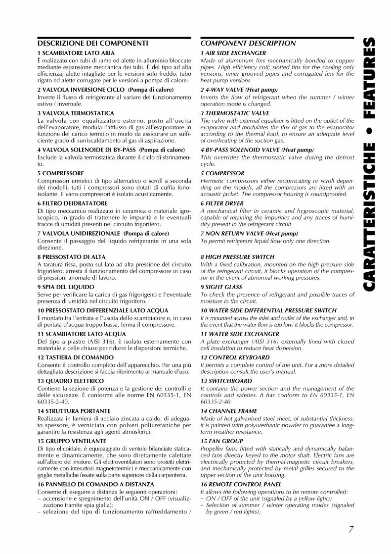
DESCRIZIONE DELL’UNITÀ
CARATTERISTICHE GENERALIIl refrigeratore è un’unità per la produzione di acqua freddae calda (pompe di calore NRA H) per impianti tecnologici.Le unità hanno grado di protezione IP 24.
VERSIONI DISPONIBILIGrandezze disponibili con gas R22 (bicompressore):NRA 202 - 252 - 302 - 352 - 402 - 502NRA 202 H - 252 H - 302 H - 352 H - 402 H - 502 H
Grandezze disponibili con gas R22 (monocompressore):NRA 201 - 251 - 301 - 211 H - 261 H - 311 H
Grandezze disponibili con gas R407C:NRA 2027 - 2527 - 3027 - 3527 - 4027 - 5027
Tali grandezze possono essere richieste con recuperatoreparziale di calore (aggiungere la lettera D alla sigla com-merciale):le unità sono equipaggiate di scambiatori che consentono direcuperare parte del calore di condensazione per soddisfarela contemporanea richiesta d’acqua refrigerata e calda. Le unità (D) sono già dotate dell’accessorio DCPX.
UNIT DESCRIPTION
MAIN DESCRIPTIONThe chiller is a unit for the production of cold and hot water(heat pump NRA H) for technical plants.Protection category is IP 24.
VERSIONS AVAILABLESizes available with gas R22 (bicompressor):NRA 202 - 252 - 302 - 352 - 402 - 502NRA 202 H - 252 H - 302 H - 352 H - 402 H - 502 H
Sizes available with gas R22 (monocompressor):NRA 201 - 251 - 301 - 211 H - 261 H - 311 H
Sizes available with gas R407C:NRA 2027 - 2527 - 3027 - 3527 - 4027 - 5027
These sizes can be ordered with partial heat recovery unit (add the letter D to the sales code): units are equipped with heat exchangers for partial recoveryof condensing heat, for simultaneous production of hot andchilled water.The (D) units are already fitted with the accessory DCPX.
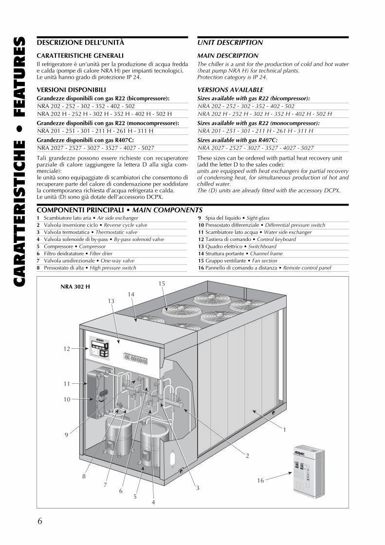
1 Scambiatore lato aria • Air side exchanger2 Valvola inversione ciclo • Reverse cycle valve3 Valvola termostatica • Thermostatic valve4 Valvola solenoide di by-pass • By-pass solenoid valve5 Compressore • Compressor6 Filtro deidratatore • Filter drier7 Valvola unidirezionale • One-way valve8 Pressostato di alta • High pressure switch
9 Spia del liquido • Sight-glass10 Pressostato differenziale • Differential pressure switch11 Scambiatore lato acqua • Water side exchanger12 Tastiera di comando • Control keyboard13 Quadro elettrico • Switchboard14 Struttura portante • Channel frame15 Gruppo ventilante • Fan section16 Pannello di comando a distanza • Remote control panel
COMPONENTI PRINCIPALI • MAIN COMPONENTS
NRA 302 H
7
CARATTERIS
TIC
HE •
FEATURESDESCRIZIONE DEI COMPONENTI
1 SCAMBIATORE LATO ARIA È realizzato con tubi di rame ed alette in alluminio bloccatemediante espansione meccanica dei tubi. È del tipo ad altaefficienza; alette intagliate per le versioni solo freddo, tuborigato ed alette corrugate per le versioni a pompa di calore.
2 VALVOLA INVERSIONE CICLO (Pompa di calore)Inverte il flusso di refrigerante al variare del funzionamentoestivo / invernale.
3 VALVOLA TERMOSTATICALa valvola con equalizzatore esterno, posto all’uscitadell’evaporatore, modula l’afflusso di gas all’evaporatore infunzione del carico termico in modo da assicurare un suffi-ciente grado di surriscaldamento al gas di aspirazione.
4 VALVOLA SOLENOIDE DI BY-PASS (Pompa di calore)Esclude la valvola termostatica durante il ciclo di sbrinamen-to.
5 COMPRESSORE Compressori ermetici di tipo alternativo o scroll a secondadei modelli, tutti i compressori sono dotati di cuffia fono-isolante. Il vano compressori è isolato acusticamente.
6 FILTRO DEIDRATATOREDi tipo meccanico realizzato in ceramica e materiale igro-scopico, in grado di trattenere le impurità e le eventualitracce di umidità presenti nel circuito frigorifero.
7 VALVOLA UNIDIREZIONALE (Pompa di calore)Consente il passaggio del liquido refrigerante in una soladirezione.
8 PRESSOSTATO DI ALTA A taratura fissa, posto sul lato ad alta pressione del circuitofrigorifero, arresta il funzionamento del compressore in casodi pressioni anomale di lavoro.
9 SPIA DEL LIQUIDOServe per verificare la carica di gas frigorigeno e l’eventualepresenza di umidità nel circuito frigorifero.
10 PRESSOSTATO DIFFERENZIALE LATO ACQUAÈ montato tra l’entrata e l’uscita dello scambiatore e, in casodi portata d’acqua troppo bassa, ferma il compressore.
11 SCAMBIATORE LATO ACQUADel tipo a piastre (AISI 316), è isolato esternamente conmateriale a celle chiuse per ridurre le dispersioni termiche.
12 TASTIERA DI COMANDOConsente il controllo completo dell’apparecchio. Per una piùdettagliata descrizione si faccia riferimento al manuale d’uso.
13 QUADRO ELETTRICOContiene la sezione di potenza e la gestione dei controlli edelle sicurezze. È conforme alle norme EN 60335-1, EN60335-2-40.
14 STRUTTURA PORTANTERealizzata in lamiera di acciaio zincata a caldo, di adegua-to spessore, è verniciata con polveri poliuretaniche pergarantire la resistenza agli agenti atmosferici.
15 GRUPPO VENTILANTEDi tipo elicoidale, è equipaggiato di ventole bilanciate statica-mente e dinamicamente, che sono direttamente calettatesull’albero del motore. Gli elettroventilatori sono protetti elettri-camente con interuttori magnetotermici e meccanicamente congriglie metalliche fissate sulla parte superiore della carpenteria.
16 PANNELLO DI COMANDO A DISTANZAConsente di eseguire a distanza le seguenti operazioni:– accensione e spegnimento dell’unità ON / OFF (visualiz-
zazione tramite spia gialla);– selezione del tipo di funzionamento raffreddamento /
COMPONENT DESCRIPTION1 AIR SIDE EXCHANGERMade of aluminium fins mechanically bonded to copperpipes. High efficiency coil; slotted fins for the cooling onlyversions, inner grooved pipes and corrugated fins for theheat pump versions.
2 4-WAY VALVE (Heat pump)Inverts the flow of refrigerant when the summer / winteroperation mode is changed.
3 THERMOSTATIC VALVEThe valve with external equaliser is fitted on the outlet of theevaporator and modulates the flux of gas to the evaporatoraccording to the thermal load, to ensure an adequate levelof overheating of the suction gas.
4 BY-PASS SOLENOID VALVE (Heat pump)This overrides the thermostatic valve during the defrostcycle.
5 COMPRESSORHermetic compressors either reciprocating or scroll depen-ding on the models, all the compressors are fitted with anacoustic jacket. The compressor housing is soundproofed.
6 FILTER DRYERA mechanical filter in ceramic and hygroscopic material,capable of retaining the impurities and any traces of humi-dity present in the refrigerant circuit.
7 NON RETURN VALVE (Heat pump)To permit refrigerant liquid flow only one direction.
8 HIGH PRESSURE SWITCHWith a fixed calibration, mounted on the high pressure sideof the refrigerant circuit, it blocks operation of the compres-sor in the event of abnormal working pressures.
9 SIGHT GLASSTo check the presence of refrigerant and possible traces ofmoisture in the circuit.
10 WATER SIDE DIFFERENTIAL PRESSURE SWITCHIt is mounted across the inlet and outlet of the exchanger and, inthe event that the water flow is too low, it blocks the compressor.
11 WATER SIDE EXCHANGERA plate exchanger (AISI 316) externally lined with closedcell insulation to reduce heat dispersion.
12 CONTROL KEYBOARDIt permits a complete control of the unit. For a more detaileddescription consult the user's manual.
13 SWITCHBOARDIt contains the power section and the management of thecontrols and safeties. It has conform to EN 60335-1, EN60335-2-40.
14 CHANNEL FRAMEMade of hot galvanised steel sheet, of substantial thickness,it is painted with polyurethanic powder to guarantee a long-term weather resistance.
15 FAN GROUPPropeller fans, fitted with statically and dynamically balan-ced fans directly keyed to the motor shaft. Electric fans areelectrically protected by thermal-magnetic circuit breakers,and mechanically protected by metal grilles secured to theupper section of the unit housing.
16 REMOTE CONTROL PANELIt allows the following operations to be remote controlled:– ON / OFF of the unit (signaled by a yellow light);– Selection of summer / winter operating modes (signaled
by green / red lights);
8
CARATTERIS
TIC
HE •
FEATURES riscaldamento (visualizzazione tramite spia verde / rossa);
– riassunto allarmi mediante accensione di una spia rossa.Nel caso di segnalazione di avvenuto allarme, è possibileeseguire un’azione di “reset”, dal pannello remoto, agendosull’interruttore ON / OFF. Il collegamento fra l’unità ed ilpannello viene eseguito mediante cavo a 6 poli di sezione:0,5 mm2 (max. 50 m), 1 mm2 (max. 100 m).
- DESURRISCALDATOREDel tipo a piastre (AISI 316), è isolato esternamente conmateriale a celle chiuse per ridurre le dispersioni termiche.
- RUBINETTO LIQUIDO (Solo freddo)Consente di intercettare il flusso di refrigerante in caso dimanutenzione straordinaria.
- PRESSOSTATO DI BASSA (Solo freddo)A taratura fissa, posto sul lato a bassa pressione del circuitofrigorifero, arresta il funzionamento del compressore in casodi pressioni anomale di lavoro. Presente unicamente nelleversioni solo freddo, in quanto nelle versioni a pompa dicalore tale funzione è svolta dal trasduttore di bassa pressio-ne fornito di serie.
- SILENZIATORE (Solo alcune versioni)Posto sulla mandata del compressore, serve ad attenuare lepulsazioni causate dal moto del gas.Non è presente se il compressore è di tipo Scroll.
- VALVOLA SOLENOIDEInterviene allo spegnimento del compressore interrompendola migrazione di gas frigorigeno liquido verso l’evaporatore.
ORGANI DI REGOLAZIONESCHEDA A MICROPROCESSOREComposta da scheda di gestione e controllo e da scheda divisualizzazione. Funzioni svolte:
• regolazione temperatura acqua ingresso evaporatorecon termostatazione a uno o due gradini.
• ritardo avviamento compressori.• funzionamento estivo o invernale in pompa di calore
con gestione sbrinamento.• rotazione sequenza compressori.• gestione dispositivo bassa temperatura (accessorio).• conteggio ore funzionamento compressori.• start/stop.• reset.• memoria permanente degli allarmi.• autostart dopo caduta di tensione.• messaggistica multilingue.• funzionamento con controllo locale o remoto.• visualizzazione stato macchina:
ON/OFF compressori;sbrinamento;riassunto allarmi.
• gestione allarmi:alta pressione;pressostato differenziale acqua.bassa pressione;antigelo;sovraccarico compressori;sovraccarico ventilatori.
• visualizzazione dei seguenti parametri:temperatura ingresso acqua;temperatura uscita acqua;delta T;temperatura refrigerante liquido (pompa di calore);alta pressione (accessorio per solo freddo);bassa pressione (accessorio per solo freddo);tempo attesa di riavvio.
• visualizzazione allarmi.• impostazioni set:
a) senza parola d'ordine:set caldo;
– Summation alarm through a red light.In the event of an alarm signal, the unit can be reset throughthe remote control by pressing the ON/OFF switch.The connection between the unit and the panel is made bymeans of a 6 pole cable with a section of: 0,5 mm2 (max. 50m), 1 mm2 (max. 100 m).
- DESUPERHEATERA plate exchanger (AISI 316) externally lined with closedcell insulation to reduce heat dispersion.
- LIQUID CUT-OFF VALVE (Cooling only)It permits the refrigerant flow to be cut-off during repairwork.
- LOW PRESSURE SWITCH (Cooling only)With fixed calibration, it is mounted on the low pressureside of the refrigerant circuit, it blocks the compressor in theevent of abnormal working pressures. It is only found on thecooling only versions, as in the heat pump versions thisfunction is performed by the low pressure transducer fittedas standard.
- MUFFLER (Selected versions only)Installed on compressor delivery line, the silencer dampenspulsations caused by gas movement.Not present on Scroll type compressors.
- SOLENOID VALVEValve closes when compressor is shut down, preventingrefrigerant gas flow to the evaporator.
CONTROLSMICROPROCESSOR CARDComposed of a management and control card and a displaycard. The functions it performs are:
• regulation of the evaporator inlet water temperaturewith one or two step thermostatic regulation.
• compressor timing delay.• summer operation or winter as a heat pump with defro-
st management.• compressor sequence rotation.• management of low temperature control (accessory).• compressor working hourmeter.• start/stop.• reset.• permanent memory of alarms.• autostart after power cuts.• multilingual messages.• operation with local or remote control.• machine status display:
compressor ON/OFF;defrost;summation alarm.
• alarm management:high pressure;water differential pressure switch.low pressure;antifreeze;compressor overload;fan overload.
• visualisation of the following parameters:water inlet temperature;water outlet temperature;delta T;refrigerant liquid temperature (heat pump);high pressure (accessory for cooling only);low pressure (accessory for cooling only);stand-by time for restart.
• alarm visualisation.• set points adjustment:
a) without password:heating set point;
9
CARATTERIS
TIC
HE •
FEATURESset freddo;
differenziale totale;differenziale gradino.
b) con parola d'ordine:set antigelo;tempo esclusione bassa pressione;pressione aspirazione inizio sbrinamento;temperatura refrigerante liquido fine sbrinamento;linguaggio display;codice di accesso.
Di seguito sono descritte in dettaglio le principali funzionigestite dalla scheda a microprocessore. Per ulteriori infor-mazioni , si veda il manuale utente.
– ACCENSIONE-SPEGNIMENTO COMPRESSORILa scheda gestisce l'accensione e lo spegnimento dei com-pressori in funzione della temperatura dell'acqua di ritornodall'impianto. La lettura delle temperature viene effettuatatramite sonda/e poste in ingresso allo scambiatore.
– TEMPORIZZAZIONE DEI COMPRESSORI E DEI VENTILATORIDi seguito sono elencati tutti i tempi di attesa tra un avvia-
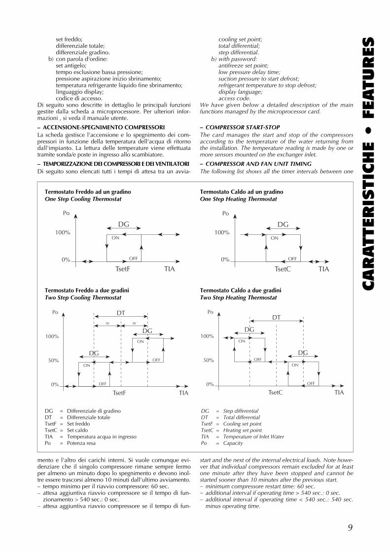
mento e l'altro dei carichi interni. Si vuole comunque evi-denziare che il singolo compressore rimane sempre fermoper almeno un minuto dopo lo spegnimento e devono inol-tre essere trascorsi almeno 10 minuti dall’ultimo avviamento.– tempo minimo per il riavvio compressore: 60 sec.– attesa aggiuntiva riavvio compressore se il tempo di fun-
zionamento > 540 sec.: 0 sec.– attesa aggiuntiva riavvio compressore se il tempo di fun-
cooling set point;total differential;step differential.
b) with password:antifreeze set point;low pressure delay time;suction pressure to start defrost;refrigerant temperature to stop defrost;display language;access code.
We have given below a detailed description of the mainfunctions managed by the microprocessor card.
– COMPRESSOR START-STOPThe card manages the start and stop of the compressorsaccording to the temperature of the water returning fromthe installation. The temperature reading is made by one ormore sensors mounted on the exchanger inlet.
– COMPRESSOR AND FAN UNIT TIMINGThe following list shows all the timer intervals between one
start and the next of the internal electrical loads. Note howe-ver that individual compressors remain excluded for at leastone minute after they have been stopped and cannot bestarted sooner than 10 minutes after the previous start.– minimum compressore restart time: 60 sec.– additional interval if operating time > 540 sec.: 0 sec.– additional interval if operating time < 540 sec.: 540 sec.
minus operating time.
TsetF TIA
DG
ON
OFF0%
100%
Po
TsetC TIA
DG
ON
OFF0%
100%
Po
TsetF TIA
DT
DG
DG
ON
ON
OFF
OFF
0%
50%
100%
Po
= =
TsetC TIA
DG
DG
DT
ON
ON
OFF
OFF
0%
50%
100%
Po
Termostato Freddo ad un gradinoOne Step Cooling Thermostat
Termostato Caldo ad un gradinoOne Step Heating Thermostat
Termostato Freddo a due gradiniTwo Step Cooling Thermostat
Termostato Caldo a due gradiniTwo Step Heating Thermostat
DG = Differenziale di gradinoDT = Differenziale totaleTsetF = Set freddoTsetC = Set caldoTIA = Temperatura acqua in ingressoPo = Potenza resa
DG = Step differentialDT = Total differentialTsetF = Cooling set pointTsetC = Heating set pointTIA = Temperature of Inlet WaterPo = Capacity
10
CARATTERIS
TIC
HE •
FEATURES zionam. < 540 sec.: 540sec. - tempo di funzion.
– ritardo tra compressori: 5 secondi.Alla richiesta d’avviamento del compressore, il microprocesso-re comanda la partenza dei ventilatori e l’apertura della valvolasolenoide del liquido del circuito interessato e successivamentevengono avviati i compressori. Questo consente di ridurre ilrapporto di compressione e quindi la corrente di spunto.
– AUTOSTARTRiavvia l’unità dopo mancanza di tensione. La scheda amicroprocessore è dotata di particolari memorie che per-mettono di memorizzare, permanentemente, le impostazio-ni di funzionamento dell’unità prima dell’interruzione ditensione.Al ritorno di tensione, se il parametro AUTOSTART è:
– 0 (Off): la macchina non riparte;– 1 (On): la macchina riparte anche se era in Stand-By;– 2 (Auto): la macchina si riconfigura come al momento
della mancanza di tensione.
– ROTAZIONE DEL FUNZIONAMENTO DEI COMPRESSORIIl microprocessore conteggia le ore di funzionamento deicompressori e con queste gestisce la rotazione dei compres-sori. È possibile azzerare questi parametri dal pannello abordo macchina (solo con il codice di accesso).
– GESTIONE DEGLI ALLARMILa scheda elettronica gestisce le anomalie di funzionamentoin pre-allarmi ed allarmi.I preallarmi sono intesi come segnalazioni di temporaneeanomalie di funzionamento provocate da elementi esterni;esse comportano il passaggio della macchina dallo stato difunzionamento allo stato di stand-by e vengono segnalatesul display pannello comandi. Quando la scheda rileva chetali anomalie sono state eliminate la macchina riparte auto-maticamente senza necessità di essere resettata.La scheda elettronica gestisce il passaggio in allarme da pre-allarme quando questo continua a persistere, bloccando ilfunzionamento del circuito interessato.La scheda a microprocessore segnala l’intervento di unallarme mediante l’accensione di un led rosso sia sul pan-nello a bordo macchina sia sul pannello comandi remoto.È inoltre a disposizione sulla scheda un contatto pulito indeviazione che viene attivato in caso d’allarme (morsettieraM1: V = 250V, Imax = 1 A).Il microprocessore memorizza in modo permanente gliallarmi intervenuti: ad esempio la mancanza di tensionesubito dopo l’intervento di un allarme non ne comporta lacancellazione, e, al momento del ritorno di tensione, lamacchina non riparte e continua a segnalare l’allarme inter-venuto.Se l'allarme interessa un solo circuito, viene fermato soloquesto, se è in comune vengono fermati entrambi i circuiti.Per riattivare la macchina o il circuito in allarme, dopo avereliminato la causa dell'intervento, è necessario premere iltasto reset sul pannello a bordo macchina.Per effettuare il “reset” dal pannello remoto si azioni unavolta in rapida successione il tasto ON / OFF; tale operazio-ne è effettuabile per non più di due volte in un’ora.Per un elenco completo degli allarmi, si consulti "Utilizzodel pannello", alla voce "Visualizzazione degli allarmi inter-venuti" nel manuale d’uso. Gli allarmi flussostato e altapressione sono delle sicurezze principali e agiscono diretta-mente sulle bobine dei carichi, indipendentemente dallascheda.
– ELETTROPOMPA DEL CIRCUITO DELL'ACQUA REFRIGERATAL'elettropompa viene attivata quando la macchina vieneaccesa e resta attiva per tutto il tempo in cui l’unità è accesaindipendentemente dal funzionamento dei compressori.Quando la macchina viene spenta, la scheda a micropro-cessore ferma pure l’elettropompa.Il comando pompa è disponibile ai morsetti 1 e 2 (MPO)della morsettiera M2 (V = 230V Imax = 0,5 A).
– delay from one compressor to the next: 5 secondi.When the compressor start signal is received, the micro-processor starts the fan units, opens the relevant liquidphase solenoid valve and then starts the compressors.These precautions serve to reduce the compression ratio,thereby restricting current absorption at start up.
– AUTO-STARTThis function restarts the appliance following power loss. Themicroprocessor card is equipped with special memory chipsthat enable the settings present before power loss to be retai-ned and reactivated when power is restored.When power returns, if the SELF-START parameter is set to:
– 0 (Off): the unit will not restart;– 1 (On): the unit restarts, even if it was in stand-by mode
at the time of power loss;– 2 (Auto): the unit assumes the same status that was acti-
ve at the time of power loss.
– COMPRESSOR RUN SEQUENCEThe microprocessor keeps a check on operating hours of thecompressors and uses this information as a basis for sequen-ce rotation. These parameters can be reset from the localmachine control panel (password needed).
– PRE-ALARMS AND ALARMSOperation failures are indicated by pre-alarms and alarmsadministrated by the electronic card.Prealarms are administrated by the electronic card in theform of signals regarding temporary functional anomalieswith external causes; alarms cause the unit to enter stand-bymode and they are shown on the control panel display.When the card detects that the various prealarms have beenremedied, it starts the unit automatically without requiring areset procedure.When the pre-alarm does not stop, the electronic card cau-ses the unit to pass from pre-alarm to alarm and stops thecooling circuit operation.The microprocessor control card informs the periphery ofthe alarm by switching on a red LED on the machine andremote control panels.The card is also equipped with a voltage-free contact that isactivated in the presence of alarms (terminal board M1: V =250V, Imax = 1 A).The microprocessor card stores alarms in a non-voltatilememory. This means, for example, that a power loss imme-diately following an alarm will not cancel the alarm. Instead,when power returns the alarm will reappear and the unitwill not restart until it has been eliminated.If the alarm is relative to just one circuit, then only the affec-ted circuit is disconnected. If the circuit in question is com-mon to both compressors then both circuits are disconnec-ted. To restart the unit or the affected circuit, remedy thecause of the alarm and then press the reset button on thelocal control panel.To perform a reset from the remote panel press ON / OFF inrapid succession; this reset procedure is possible no morethan twice in any one hour.For a complete list of alarms, refer to "Using the controlpanel", subheading "Alarm displays" in the user manual.Flow switch and high pressure alarms are safety-criticalevents and they trip the electrical feeding relays indepen-dently from the control card.
– CHILLED WATER PUMPThe chilled water pump is connected when the unit is swit-ched on and keeps running for as long as the unit is in ope-ration regardless of compressor status.When the unit is switched off the microprocessor controlcard also disconnects the pump.Terminals 1 and 2 (MPO) of terminal board M2 (V = 230V,Imax = 0,5 A) can activate the pump.
11
CARATTERIS
TIC
HE •
FEATURESSe il consenso pompa della scheda non viene utilizzato, è
obbligatorio che la pompa venga accesa prima della mac-china e lasciata sempre in funzione durante il funzionamen-to della macchina.
ORGANI DI REGOLAZIONE E DI CONTROLLO- sistema di interblocco porta.- magnetotermico protezione compressori.- magnetotermico protezione ventilatori.- magnetotermico protezione ausiliario.- resistenza carter compressori (escluso NRA 352 / 3527 /
201 / 251).- pressostati di bassa e alta pressione.- pressostato differenziale lato acqua.- trasduttori di pressione TP1 e TP2 (accessori).- resistenza elettrica evaporatori (accessorio).- pannello comandi remoto semplificato composto da:
commutatore ON/OFF/Reset;commutatore Estate/Inverno;
segnalazione riassunto allarmi.
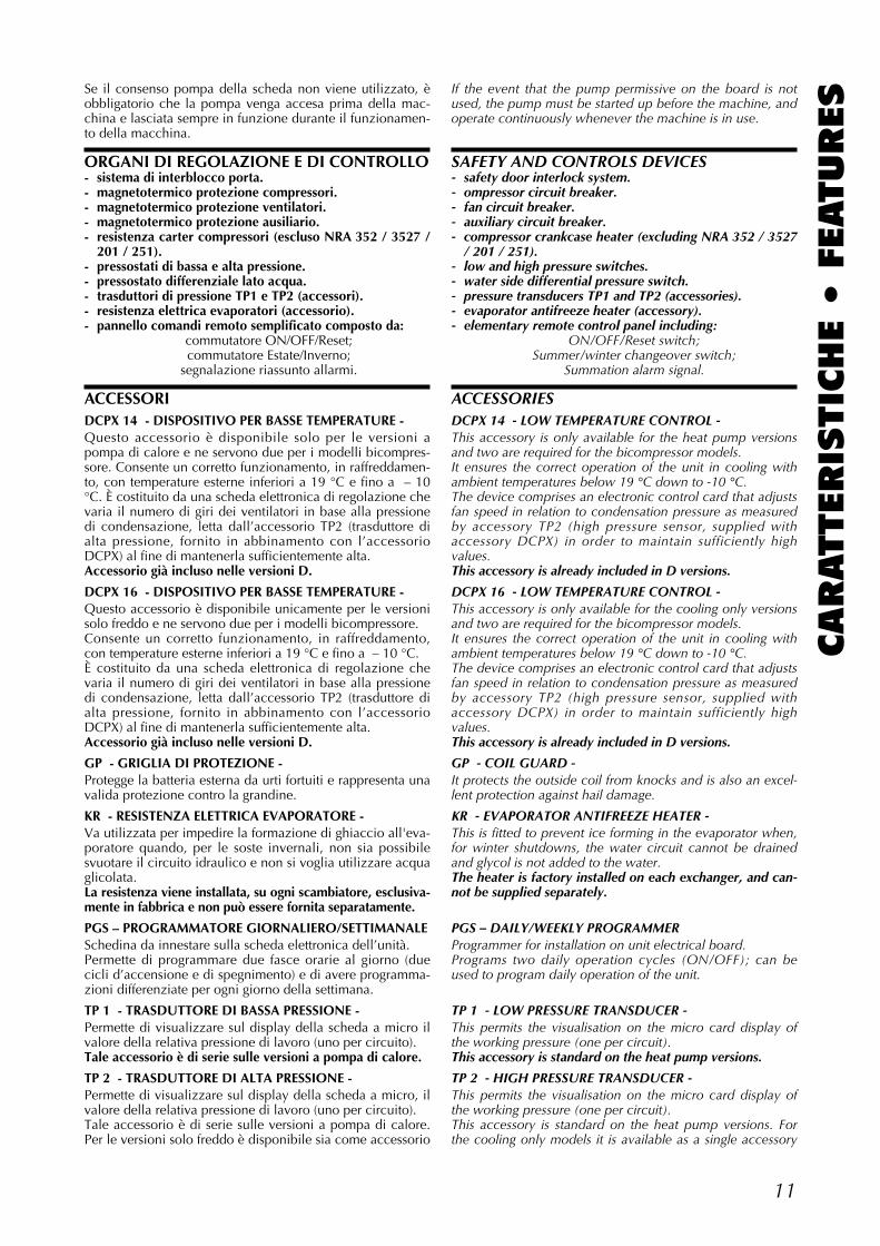
ACCESSORIDCPX 14 - DISPOSITIVO PER BASSE TEMPERATURE -Questo accessorio è disponibile solo per le versioni apompa di calore e ne servono due per i modelli bicompres-sore. Consente un corretto funzionamento, in raffreddamen-to, con temperature esterne inferiori a 19 °C e fino a – 10°C. È costituito da una scheda elettronica di regolazione chevaria il numero di giri dei ventilatori in base alla pressionedi condensazione, letta dall’accessorio TP2 (trasduttore dialta pressione, fornito in abbinamento con l’accessorioDCPX) al fine di mantenerla sufficientemente alta.Accessorio già incluso nelle versioni D.
DCPX 16 - DISPOSITIVO PER BASSE TEMPERATURE -Questo accessorio è disponibile unicamente per le versionisolo freddo e ne servono due per i modelli bicompressore.Consente un corretto funzionamento, in raffreddamento,con temperature esterne inferiori a 19 °C e fino a – 10 °C.È costituito da una scheda elettronica di regolazione chevaria il numero di giri dei ventilatori in base alla pressionedi condensazione, letta dall’accessorio TP2 (trasduttore dialta pressione, fornito in abbinamento con l’accessorioDCPX) al fine di mantenerla sufficientemente alta.Accessorio già incluso nelle versioni D.
GP - GRIGLIA DI PROTEZIONE -Protegge la batteria esterna da urti fortuiti e rappresenta unavalida protezione contro la grandine.
KR - RESISTENZA ELETTRICA EVAPORATORE -Va utilizzata per impedire la formazione di ghiaccio all'eva-poratore quando, per le soste invernali, non sia possibilesvuotare il circuito idraulico e non si voglia utilizzare acquaglicolata.La resistenza viene installata, su ogni scambiatore, esclusiva-mente in fabbrica e non può essere fornita separatamente.
PGS – PROGRAMMATORE GIORNALIERO/SETTIMANALESchedina da innestare sulla scheda elettronica dell’unità.Permette di programmare due fasce orarie al giorno (duecicli d’accensione e di spegnimento) e di avere programma-zioni differenziate per ogni giorno della settimana.
TP 1 - TRASDUTTORE DI BASSA PRESSIONE -Permette di visualizzare sul display della scheda a micro ilvalore della relativa pressione di lavoro (uno per circuito).Tale accessorio è di serie sulle versioni a pompa di calore.
TP 2 - TRASDUTTORE DI ALTA PRESSIONE -Permette di visualizzare sul display della scheda a micro, ilvalore della relativa pressione di lavoro (uno per circuito).Tale accessorio è di serie sulle versioni a pompa di calore.Per le versioni solo freddo è disponibile sia come accessorio
If the event that the pump permissive on the board is notused, the pump must be started up before the machine, andoperate continuously whenever the machine is in use.
SAFETY AND CONTROLS DEVICES- safety door interlock system.- ompressor circuit breaker.- fan circuit breaker.- auxiliary circuit breaker.- compressor crankcase heater (excluding NRA 352 / 3527
/ 201 / 251).- low and high pressure switches.- water side differential pressure switch.- pressure transducers TP1 and TP2 (accessories).- evaporator antifreeze heater (accessory).- elementary remote control panel including:
ON/OFF/Reset switch;Summer/winter changeover switch;
Summation alarm signal.
ACCESSORIESDCPX 14 - LOW TEMPERATURE CONTROL -This accessory is only available for the heat pump versionsand two are required for the bicompressor models.It ensures the correct operation of the unit in cooling withambient temperatures below 19 °C down to -10 °C.The device comprises an electronic control card that adjustsfan speed in relation to condensation pressure as measuredby accessory TP2 (high pressure sensor, supplied withaccessory DCPX) in order to maintain sufficiently highvalues.This accessory is already included in D versions.
DCPX 16 - LOW TEMPERATURE CONTROL -This accessory is only available for the cooling only versionsand two are required for the bicompressor models.It ensures the correct operation of the unit in cooling withambient temperatures below 19 °C down to -10 °C.The device comprises an electronic control card that adjustsfan speed in relation to condensation pressure as measuredby accessory TP2 (high pressure sensor, supplied withaccessory DCPX) in order to maintain sufficiently highvalues.This accessory is already included in D versions.
GP - COIL GUARD -It protects the outside coil from knocks and is also an excel-lent protection against hail damage.
KR - EVAPORATOR ANTIFREEZE HEATER -This is fitted to prevent ice forming in the evaporator when,for winter shutdowns, the water circuit cannot be drainedand glycol is not added to the water.The heater is factory installed on each exchanger, and can-not be supplied separately.
PGS – DAILY/WEEKLY PROGRAMMERProgrammer for installation on unit electrical board.Programs two daily operation cycles (ON/OFF); can beused to program daily operation of the unit.
TP 1 - LOW PRESSURE TRANSDUCER -This permits the visualisation on the micro card display ofthe working pressure (one per circuit).This accessory is standard on the heat pump versions.
TP 2 - HIGH PRESSURE TRANSDUCER -This permits the visualisation on the micro card display ofthe working pressure (one per circuit).This accessory is standard on the heat pump versions. Forthe cooling only models it is available as a single accessory
12
CARATTERIS
TIC
HE •
FEATURES
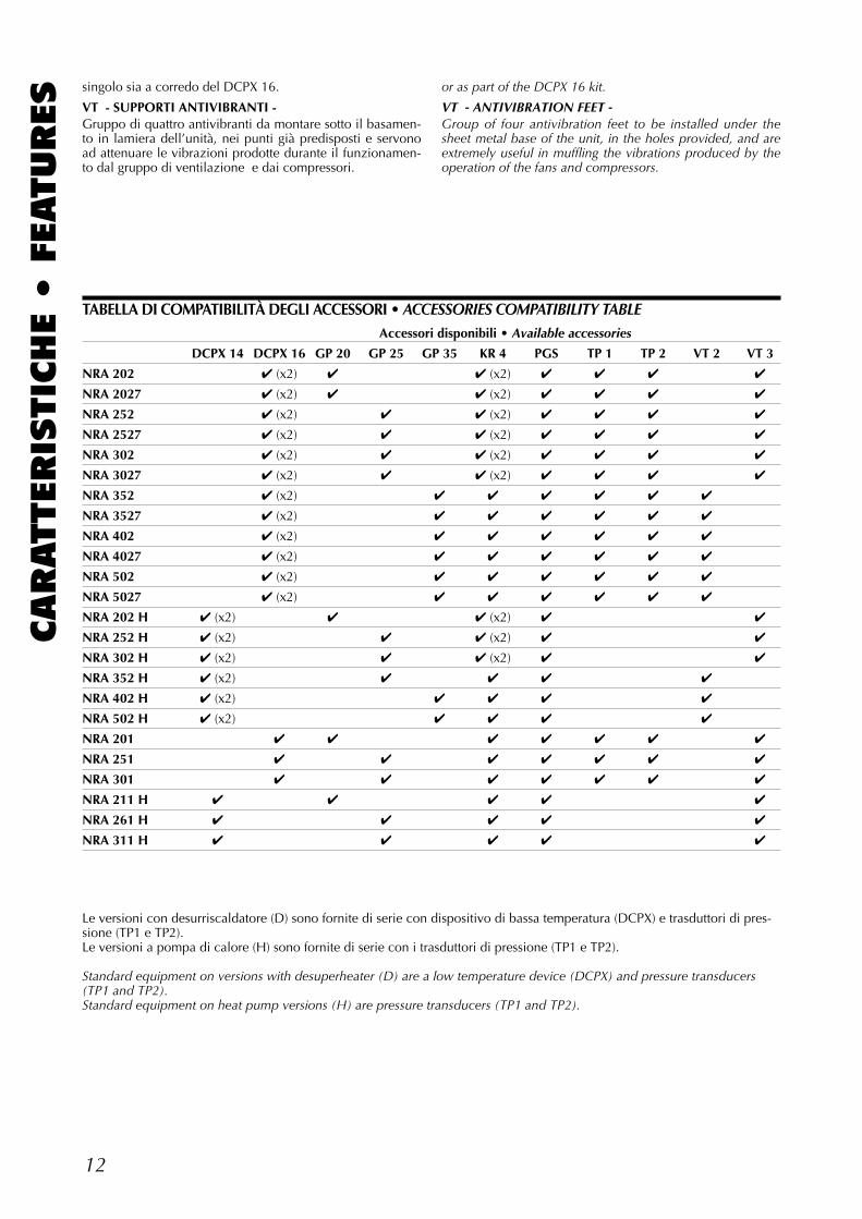
Accessori disponibili • Available accessories
DCPX 14 DCPX 16 GP 20 GP 25 GP 35 KR 4 PGS TP 1 TP 2 VT 2 VT 3
NRA 202 ✔ (x2) ✔ ✔ (x2) ✔ ✔ ✔ ✔
NRA 2027 ✔ (x2) ✔ ✔ (x2) ✔ ✔ ✔ ✔
NRA 252 ✔ (x2) ✔ ✔ (x2) ✔ ✔ ✔ ✔
NRA 2527 ✔ (x2) ✔ ✔ (x2) ✔ ✔ ✔ ✔
NRA 302 ✔ (x2) ✔ ✔ (x2) ✔ ✔ ✔ ✔
NRA 3027 ✔ (x2) ✔ ✔ (x2) ✔ ✔ ✔ ✔
NRA 352 ✔ (x2) ✔ ✔ ✔ ✔ ✔ ✔
NRA 3527 ✔ (x2) ✔ ✔ ✔ ✔ ✔ ✔
NRA 402 ✔ (x2) ✔ ✔ ✔ ✔ ✔ ✔
NRA 4027 ✔ (x2) ✔ ✔ ✔ ✔ ✔ ✔
NRA 502 ✔ (x2) ✔ ✔ ✔ ✔ ✔ ✔
NRA 5027 ✔ (x2) ✔ ✔ ✔ ✔ ✔ ✔
NRA 202 H ✔ (x2) ✔ ✔ (x2) ✔ ✔
NRA 252 H ✔ (x2) ✔ ✔ (x2) ✔ ✔
NRA 302 H ✔ (x2) ✔ ✔ (x2) ✔ ✔
NRA 352 H ✔ (x2) ✔ ✔ ✔ ✔
NRA 402 H ✔ (x2) ✔ ✔ ✔ ✔
NRA 502 H ✔ (x2) ✔ ✔ ✔ ✔
NRA 201 ✔ ✔ ✔ ✔ ✔ ✔ ✔
NRA 251 ✔ ✔ ✔ ✔ ✔ ✔ ✔
NRA 301 ✔ ✔ ✔ ✔ ✔ ✔ ✔
NRA 211 H ✔ ✔ ✔ ✔ ✔
NRA 261 H ✔ ✔ ✔ ✔ ✔
NRA 311 H ✔ ✔ ✔ ✔ ✔
TABELLA DI COMPATIBILITÀ DEGLI ACCESSORI • ACCESSORIES COMPATIBILITY TABLE
singolo sia a corredo del DCPX 16.
VT - SUPPORTI ANTIVIBRANTI -Gruppo di quattro antivibranti da montare sotto il basamen-to in lamiera dell’unità, nei punti già predisposti e servonoad attenuare le vibrazioni prodotte durante il funzionamen-to dal gruppo di ventilazione e dai compressori.
or as part of the DCPX 16 kit.
VT - ANTIVIBRATION FEET -Group of four antivibration feet to be installed under thesheet metal base of the unit, in the holes provided, and areextremely useful in muffling the vibrations produced by theoperation of the fans and compressors.
Le versioni con desurriscaldatore (D) sono fornite di serie con dispositivo di bassa temperatura (DCPX) e trasduttori di pres-sione (TP1 e TP2).Le versioni a pompa di calore (H) sono fornite di serie con i trasduttori di pressione (TP1 e TP2).
Standard equipment on versions with desuperheater (D) are a low temperature device (DCPX) and pressure transducers(TP1 and TP2). Standard equipment on heat pump versions (H) are pressure transducers (TP1 and TP2).
13
CARATTERIS
TIC
HE •
FEATURESCRITERI DI SCELTA
Le tabelle A, B, C, D riportano, per tutti i modelli, la poten-za frigorifera, termica e l’assorbimento elettrico totale infunzione della temperatura aria esterna e della temperaturadell’acqua in uscita (∆t = 5 °C). Sono consentite interpola-zioni, ma non estrapolazioni. La tabella G riporta, in funzio-ne del salto termico dell’acqua allo scambiatore, i coeffi-cienti correttivi da applicare ai valori ricavati.Le tavole 1 e 2 riportano il diagramma delle perdite di cari-co lato acqua degli scambiatori; le curve indicano il limiteconsentito, inferiore e superiore, del valore della portatad’acqua refrigerata al fine di garantire un corretto funziona-mento. I valori ricavati dalle tavole devono essere corretti infunzione della temperatura media dell’acqua come riportatonelle tabelle di seguito ai diagrammi.La tavola 6 riporta il diagramma delle perdite di carico delfiltro acqua.La tabella E riporta la pressione e la potenza sonora emessedagli apparecchi.La tabella F riporta, in caso di funzionamento con acquaglicolata, i coefficienti correttivi da applicare ai valori nomi-nali. La tabella H riporta, in funzione del fattore di sporca-mento, i fattori di correzione da applicare ai valori riportatinei diagrammi delle perdite di carico.Le tabelle I ed L riportano le tarature dei dispositivi di con-trollo e di protezione della macchina.Per i dati elettrici si faccia riferimento al capitolo “Schemielettrici”. Per informazioni riguardanti i circuiti frigoriferi siveda il capitolo “Schemi frigoriferi”.
ESEMPIO DI SCELTASi debbano condizionare degli ambienti per i quali sianodate le seguenti condizioni di progetto:- potenza frigorifera richiesta 45 kW con aria esterna a 40
°C e acqua prodotta 7 °C.Optando per un modello a due compressori, in tabella A,nella colonna relativa a NRA 252, in corrispondenza a Tae = 40 °C e a TWu = 7 °C, si leggono:Potenza frigorifera resa: 46,7 kW;Potenza elettrica assorbita: 20,5 kW.La portata d'acqua da inviare all'evaporatore, corrisponden-te ad un salto termico di 5 °C, è pari a 8.032 l/h. La perdita di carico all'evaporatore si legge sul diagramma atav. 1 ed è pari a 23 kPa.
SELECTIONTables A, B, C, D give all the models with the cooling andheating capacities, and the total absorbed power relative tothe ambient air temperature and the outlet water temperatu-re (∆t = 5 °C). Readings within the curve are allowed butnot extrapolations.Table G gives the correction factors to apply to the variousresults relative to the water temperature differential at theexchanger.Charts 1 and 2 show the water side pressure drop curves:they indicate the upper and lower limits of the chilled waterflow required to guarantee a correct operation of the unit.The results obtained from the charts must be correctedaccording to the average water temperature as shown in thetables following the graphs.Chart 6 shows the water filter pressure drop curve.Table E gives the sound pressure and power levels of eachunit.Table F gives the correction factors to apply to the nominalvalues if glycol is added to the water.Table H shows the correction factors of the pressure dropsregarding the fouling factors.Table I and L lists the settings of the protection and controldevices fitted on the unit.For all electrical data refer to the chapter "Wiring diagrams".For information about the refrigerant circuits consult thechapter “Refrigerant circuits”.
SELECTION EXAMPLEA location must be air-conditioned with the following designconditions:- cooling capacity required 45 kW with external air tempra-
ture at 40 °C and outlet water at 7 °C.Opting for the two compressor model, in table A, columnNRA 252, in correspondence to Tae = 40 °C and Twu = 7°C, we find:Cooling capacity: 46.7 kW;Absorbed power: 20.5 kW.The water flow to supply the evaporator, corresponding to a∆T of 5 °C, is equal to 8,032 lt/h. The pressure drop at theevaporator can be obtained from the curve at chart 1 andshould result as 23 kPa.
14
CARATTERIS
TIC
HE •
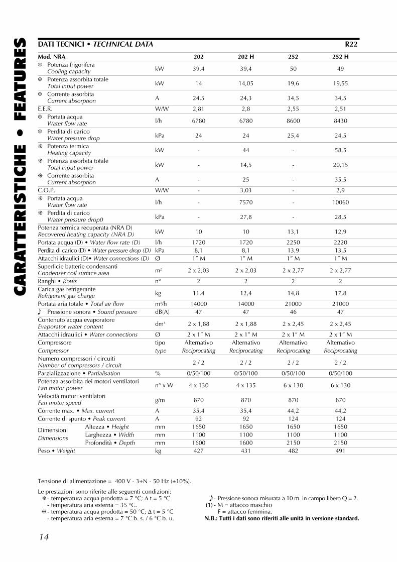
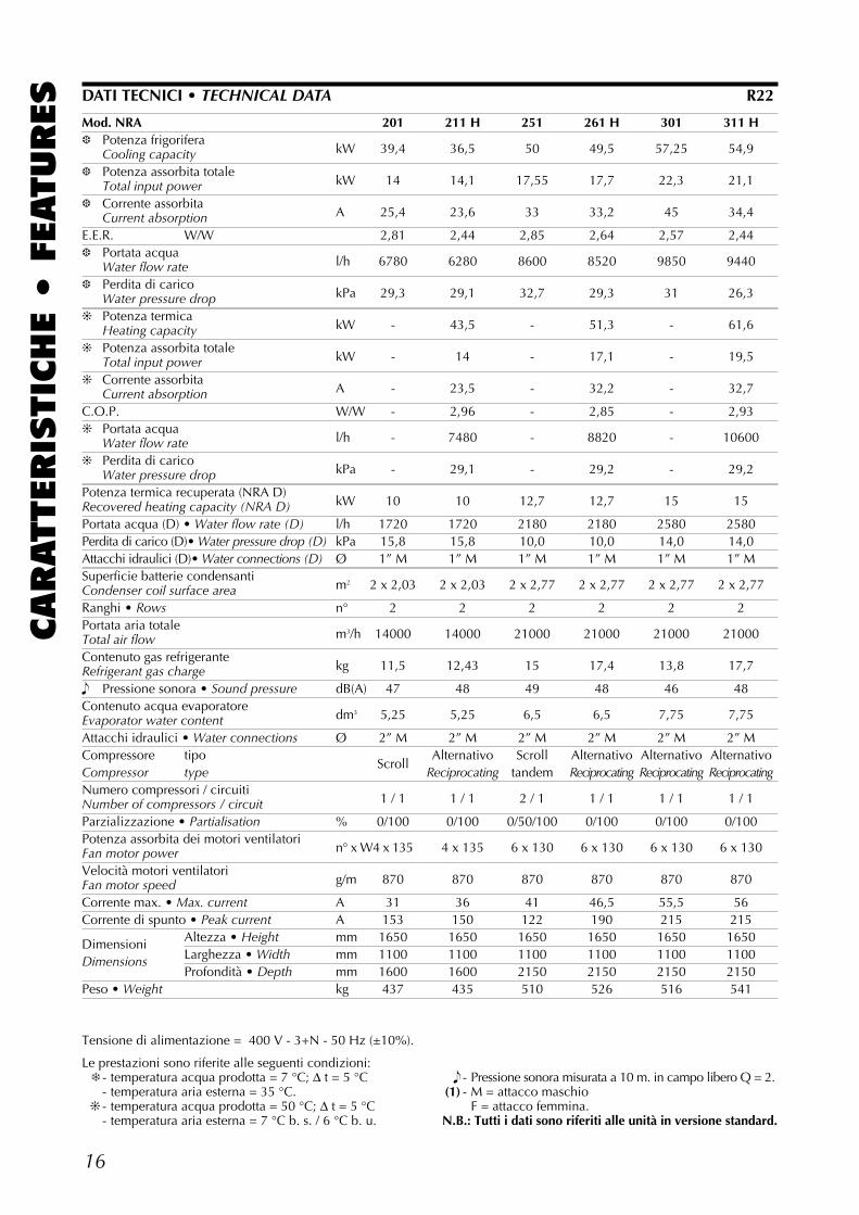
FEATURES DATI TECNICI • TECHNICAL DATA R22
Tensione di alimentazione = 400 V - 3+N - 50 Hz (±10%).
Le prestazioni sono riferite alle seguenti condizioni:❄ - temperatura acqua prodotta = 7 °C; ∆ t = 5 °C
- temperatura aria esterna = 35 °C.❊ - temperatura acqua prodotta = 50 °C; ∆ t = 5 °C
- temperatura aria esterna = 7 °C b. s. / 6 °C b. u.
� - Pressione sonora misurata a 10 m. in campo libero Q = 2.(1) - M = attacco maschio
F = attacco femmina.N.B.: Tutti i dati sono riferiti alle unità in versione standard.
Mod. NRA 202 202 H 252 252 H❆ Potenza frigorifera
kW 39,4 39,4 50 49Cooling capacity❆ Potenza assorbita totale
kW 14 14,05 19,6 19,55Total input power❆ Corrente assorbita
A 24,5 24,3 34,5 34,5Current absorptionE.E.R. W/W 2,81 2,8 2,55 2,51❆ Portata acqua
l/h 6780 6780 8600 8430Water flow rate❆ Perdita di carico
kPa 24 24 25,4 24,5Water pressure drop❊ Potenza termica
kW - 44 - 58,5Heating capacity❊ Potenza assorbita totale
kW - 14,5 - 20,15Total input power❊ Corrente assorbita
A - 25 - 35,5Current absorptionC.O.P. W/W - 3,03 - 2,9❊ Portata acqua
l/h - 7570 - 10060Water flow rate❊ Perdita di carico
kPa - 27,8 - 28,5Water pressure drop0Potenza termica recuperata (NRA D)
kW 10 10 13,1 12,9Recovered heating capacity (NRA D)Portata acqua (D) • Water flow rate (D) l/h 1720 1720 2250 2220Perdita di carico (D) • Water pressure drop (D) kPa 8,1 8,1 13,9 13,5Attacchi idraulici (D)• Water connections (D) Ø 1” M 1” M 1” M 1” MSuperficie batterie condensanti
m2 2 x 2,03 2 x 2,03 2 x 2,77 2 x 2,77Condenser coil surface areaRanghi • Rows n° 2 2 2 2Carica gas refrigerante
kg 11,4 12,4 14,8 17,8Refrigerant gas chargePortata aria totale • Total air flow m3/h 14000 14000 21000 21000� Pressione sonora • Sound pressure dB(A) 47 47 46 47Contenuto acqua evaporatore
dm3 2 x 1,88 2 x 1,88 2 x 2,45 2 x 2,45Evaporator water contentAttacchi idraulici • Water connections Ø 2 x 1” M 2 x 1” M 2 x 1” M 2 x 1” MCompressore tipo Alternativo Alternativo Alternativo AlternativoCompressor type Reciprocating Reciprocating Reciprocating ReciprocatingNumero compressori / circuiti
2 / 2 2 / 2 2 / 2 2 / 2Number of compressors / circuitParzializzazione • Partialisation % 0/50/100 0/50/100 0/50/100 0/50/100Potenza assorbita dei motori ventilatori
n° x W 4 x 130 4 x 135 6 x 130 6 x 130Fan motor powerVelocità motori ventilatori
g/m 870 870 870 870Fan motor speedCorrente max. • Max. current A 35,4 35,4 44,2 44,2Corrente di spunto • Peak current A 92 92 124 124
Dimensioni Altezza • Height mm 1650 1650 1650 1650
Dimensions Larghezza • Width mm 1100 1100 1100 1100Profondità • Depth mm 1600 1600 2150 2150
Peso • Weight kg 427 431 482 491
15
CARATTERIS
TIC
HE •
FEATURES
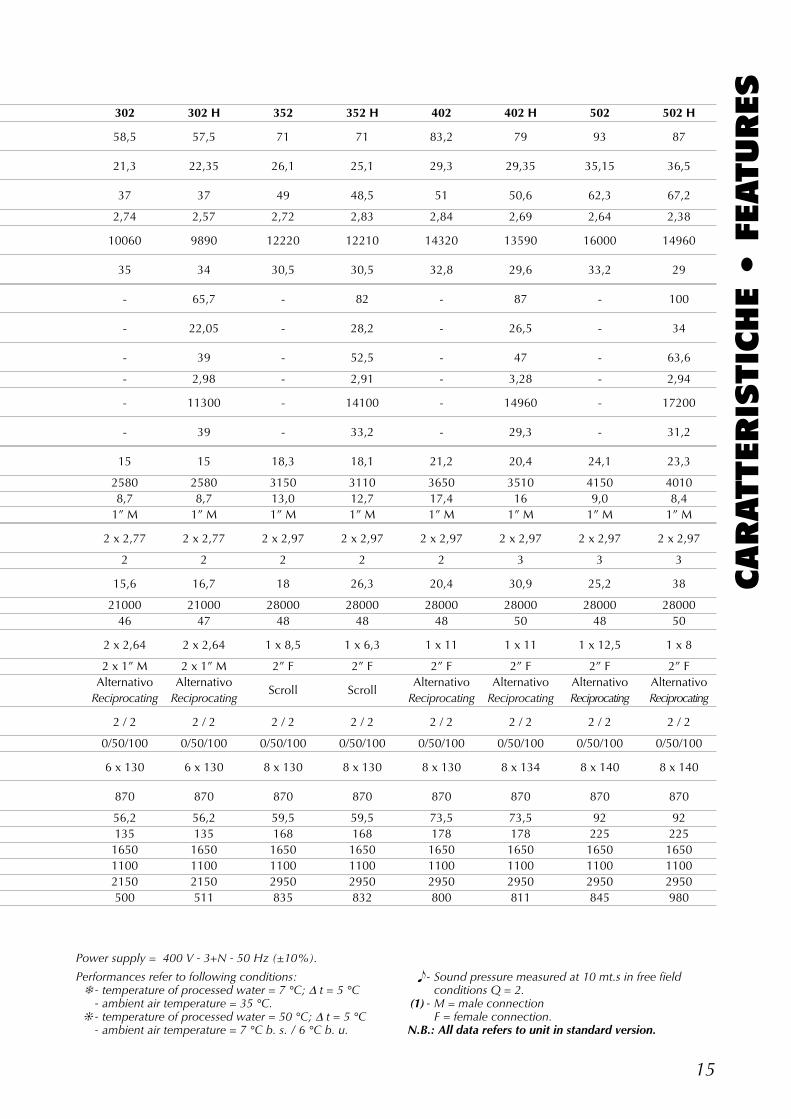
Performances refer to following conditions:❄ - temperature of processed water = 7 °C; ∆ t = 5 °C
- ambient air temperature = 35 °C.❊ - temperature of processed water = 50 °C; ∆ t = 5 °C
- ambient air temperature = 7 °C b. s. / 6 °C b. u.
� - Sound pressure measured at 10 mt.s in free field conditions Q = 2.
(1) - M = male connectionF = female connection.
N.B.: All data refers to unit in standard version.
Power supply = 400 V - 3+N - 50 Hz (±10%).
302 302 H 352 352 H 402 402 H 502 502 H
58,5 57,5 71 71 83,2 79 93 87
21,3 22,35 26,1 25,1 29,3 29,35 35,15 36,5
37 37 49 48,5 51 50,6 62,3 67,2
2,74 2,57 2,72 2,83 2,84 2,69 2,64 2,38
10060 9890 12220 12210 14320 13590 16000 14960
35 34 30,5 30,5 32,8 29,6 33,2 29
- 65,7 - 82 - 87 - 100
- 22,05 - 28,2 - 26,5 - 34
- 39 - 52,5 - 47 - 63,6
- 2,98 - 2,91 - 3,28 - 2,94
- 11300 - 14100 - 14960 - 17200
- 39 - 33,2 - 29,3 - 31,2
15 15 18,3 18,1 21,2 20,4 24,1 23,3
2580 2580 3150 3110 3650 3510 4150 40108,7 8,7 13,0 12,7 17,4 16 9,0 8,4
1” M 1” M 1” M 1” M 1” M 1” M 1” M 1” M
2 x 2,77 2 x 2,77 2 x 2,97 2 x 2,97 2 x 2,97 2 x 2,97 2 x 2,97 2 x 2,97
2 2 2 2 2 3 3 3
15,6 16,7 18 26,3 20,4 30,9 25,2 38
21000 21000 28000 28000 28000 28000 28000 2800046 47 48 48 48 50 48 50
2 x 2,64 2 x 2,64 1 x 8,5 1 x 6,3 1 x 11 1 x 11 1 x 12,5 1 x 8
2 x 1” M 2 x 1” M 2” F 2” F 2” F 2” F 2” F 2” FAlternativo Alternativo
Scroll ScrollAlternativo Alternativo Alternativo Alternativo
Reciprocating Reciprocating Reciprocating Reciprocating Reciprocating Reciprocating
2 / 2 2 / 2 2 / 2 2 / 2 2 / 2 2 / 2 2 / 2 2 / 2
0/50/100 0/50/100 0/50/100 0/50/100 0/50/100 0/50/100 0/50/100 0/50/100
6 x 130 6 x 130 8 x 130 8 x 130 8 x 130 8 x 134 8 x 140 8 x 140
870 870 870 870 870 870 870 870
56,2 56,2 59,5 59,5 73,5 73,5 92 92135 135 168 168 178 178 225 2251650 1650 1650 1650 1650 1650 1650 16501100 1100 1100 1100 1100 1100 1100 11002150 2150 2950 2950 2950 2950 2950 2950500 511 835 832 800 811 845 980
16
CARATTERIS
TIC
HE •
FEATURES
Mod. NRA 201 211 H 251 261 H 301 311 H❆ Potenza frigorifera
kW 39,4 36,5 50 49,5 57,25 54,9Cooling capacity❆ Potenza assorbita totale
kW 14 14,1 17,55 17,7 22,3 21,1Total input power❆ Corrente assorbita
A 25,4 23,6 33 33,2 45 34,4Current absorptionE.E.R. W/W 2,81 2,44 2,85 2,64 2,57 2,44❆ Portata acqua
l/h 6780 6280 8600 8520 9850 9440Water flow rate❆ Perdita di carico
kPa 29,3 29,1 32,7 29,3 31 26,3Water pressure drop❊ Potenza termica
kW - 43,5 - 51,3 - 61,6Heating capacity❊ Potenza assorbita totale
kW - 14 - 17,1 - 19,5Total input power❊ Corrente assorbita
A - 23,5 - 32,2 - 32,7Current absorptionC.O.P. W/W - 2,96 - 2,85 - 2,93❊ Portata acqua
l/h - 7480 - 8820 - 10600Water flow rate❊ Perdita di carico
kPa - 29,1 - 29,2 - 29,2Water pressure dropPotenza termica recuperata (NRA D)
kW 10 10 12,7 12,7 15 15Recovered heating capacity (NRA D)Portata acqua (D) • Water flow rate (D) l/h 1720 1720 2180 2180 2580 2580Perdita di carico (D)• Water pressure drop (D) kPa 15,8 15,8 10,0 10,0 14,0 14,0Attacchi idraulici (D)• Water connections (D) Ø 1” M 1” M 1” M 1” M 1” M 1” MSuperficie batterie condensanti
m2 2 x 2,03 2 x 2,03 2 x 2,77 2 x 2,77 2 x 2,77 2 x 2,77Condenser coil surface areaRanghi • Rows n° 2 2 2 2 2 2Portata aria totale
m3/h 14000 14000 21000 21000 21000 21000Total air flowContenuto gas refrigerante
kg 11,5 12,43 15 17,4 13,8 17,7Refrigerant gas charge� Pressione sonora • Sound pressure dB(A) 47 48 49 48 46 48Contenuto acqua evaporatore
dm3 5,25 5,25 6,5 6,5 7,75 7,75Evaporator water contentAttacchi idraulici • Water connections Ø 2” M 2” M 2” M 2” M 2” M 2” MCompressore tipo
ScrollAlternativo Scroll Alternativo Alternativo Alternativo
Compressor type Reciprocating tandem Reciprocating Reciprocating ReciprocatingNumero compressori / circuiti
1 / 1 1 / 1 2 / 1 1 / 1 1 / 1 1 / 1Number of compressors / circuitParzializzazione • Partialisation % 0/100 0/100 0/50/100 0/100 0/100 0/100Potenza assorbita dei motori ventilatori
n° x W4 x 135 4 x 135 6 x 130 6 x 130 6 x 130 6 x 130Fan motor powerVelocità motori ventilatori
g/m 870 870 870 870 870 870Fan motor speedCorrente max. • Max. current A 31 36 41 46,5 55,5 56Corrente di spunto • Peak current A 153 150 122 190 215 215
Dimensioni Altezza • Height mm 1650 1650 1650 1650 1650 1650
Dimensions Larghezza • Width mm 1100 1100 1100 1100 1100 1100Profondità • Depth mm 1600 1600 2150 2150 2150 2150
Peso • Weight kg 437 435 510 526 516 541
DATI TECNICI • TECHNICAL DATA R22
Tensione di alimentazione = 400 V - 3+N - 50 Hz (±10%).
Le prestazioni sono riferite alle seguenti condizioni:❄ - temperatura acqua prodotta = 7 °C; ∆ t = 5 °C
- temperatura aria esterna = 35 °C.❊ - temperatura acqua prodotta = 50 °C; ∆ t = 5 °C
- temperatura aria esterna = 7 °C b. s. / 6 °C b. u.
� - Pressione sonora misurata a 10 m. in campo libero Q = 2.(1) - M = attacco maschio
F = attacco femmina.N.B.: Tutti i dati sono riferiti alle unità in versione standard.
17
CARATTERIS
TIC
HE •
FEATURES
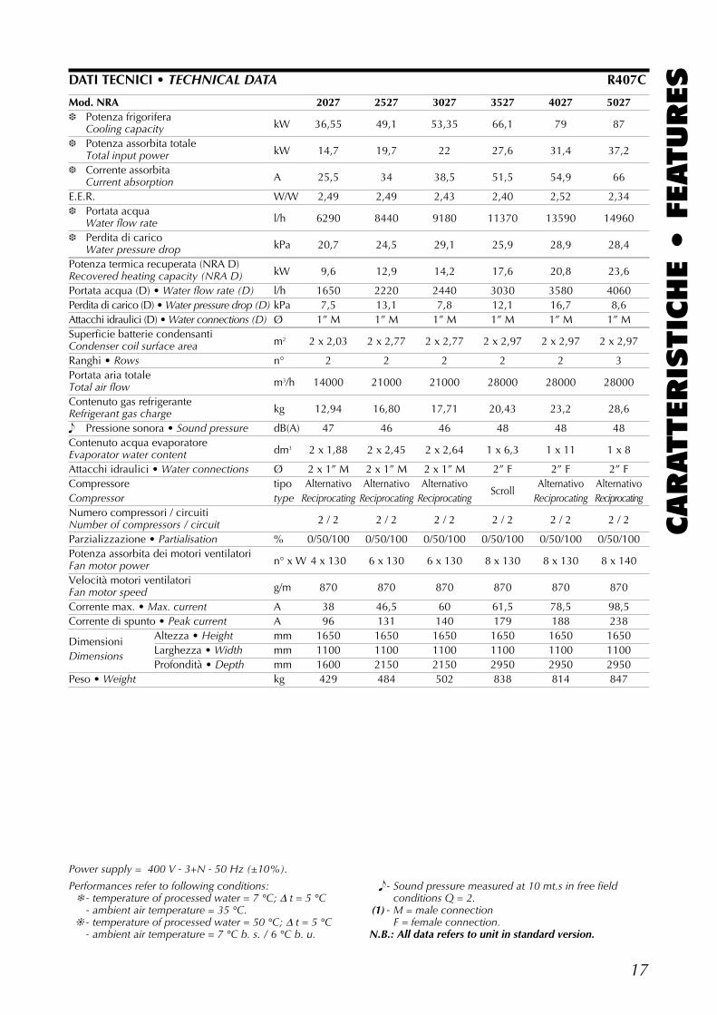
Mod. NRA 2027 2527 3027 3527 4027 5027❆ Potenza frigorifera
kW 36,55 49,1 53,35 66,1 79 87Cooling capacity❆ Potenza assorbita totale
kW 14,7 19,7 22 27,6 31,4 37,2Total input power❆ Corrente assorbita
A 25,5 34 38,5 51,5 54,9 66Current absorptionE.E.R. W/W 2,49 2,49 2,43 2,40 2,52 2,34❆ Portata acqua
l/h 6290 8440 9180 11370 13590 14960Water flow rate❆ Perdita di carico
kPa 20,7 24,5 29,1 25,9 28,9 28,4Water pressure dropPotenza termica recuperata (NRA D)
kW 9,6 12,9 14,2 17,6 20,8 23,6Recovered heating capacity (NRA D)Portata acqua (D) • Water flow rate (D) l/h 1650 2220 2440 3030 3580 4060Perdita di carico (D) • Water pressure drop (D) kPa 7,5 13,1 7,8 12,1 16,7 8,6Attacchi idraulici (D) • Water connections (D) Ø 1” M 1” M 1” M 1” M 1” M 1” MSuperficie batterie condensanti
m2 2 x 2,03 2 x 2,77 2 x 2,77 2 x 2,97 2 x 2,97 2 x 2,97Condenser coil surface areaRanghi • Rows n° 2 2 2 2 2 3Portata aria totale
m3/h 14000 21000 21000 28000 28000 28000Total air flowContenuto gas refrigerante
kg 12,94 16,80 17,71 20,43 23,2 28,6Refrigerant gas charge� Pressione sonora • Sound pressure dB(A) 47 46 46 48 48 48Contenuto acqua evaporatore
dm3 2 x 1,88 2 x 2,45 2 x 2,64 1 x 6,3 1 x 11 1 x 8Evaporator water contentAttacchi idraulici • Water connections Ø 2 x 1” M 2 x 1” M 2 x 1” M 2” F 2” F 2” FCompressore tipo Alternativo Alternativo Alternativo
ScrollAlternativo Alternativo
Compressor type Reciprocating Reciprocating Reciprocating Reciprocating ReciprocatingNumero compressori / circuiti
2 / 2 2 / 2 2 / 2 2 / 2 2 / 2 2 / 2Number of compressors / circuitParzializzazione • Partialisation % 0/50/100 0/50/100 0/50/100 0/50/100 0/50/100 0/50/100Potenza assorbita dei motori ventilatori
n° x W 4 x 130 6 x 130 6 x 130 8 x 130 8 x 130 8 x 140Fan motor powerVelocità motori ventilatori
g/m 870 870 870 870 870 870Fan motor speedCorrente max. • Max. current A 38 46,5 60 61,5 78,5 98,5Corrente di spunto • Peak current A 96 131 140 179 188 238
Dimensioni Altezza • Height mm 1650 1650 1650 1650 1650 1650
Dimensions Larghezza • Width mm 1100 1100 1100 1100 1100 1100Profondità • Depth mm 1600 2150 2150 2950 2950 2950
Peso • Weight kg 429 484 502 838 814 847
DATI TECNICI • TECHNICAL DATA R407C
Performances refer to following conditions:❄ - temperature of processed water = 7 °C; ∆ t = 5 °C
- ambient air temperature = 35 °C.❊ - temperature of processed water = 50 °C; ∆ t = 5 °C
- ambient air temperature = 7 °C b. s. / 6 °C b. u.
� - Sound pressure measured at 10 mt.s in free field conditions Q = 2.
(1) - M = male connectionF = female connection.
N.B.: All data refers to unit in standard version.
Power supply = 400 V - 3+N - 50 Hz (±10%).
18
CARATTERIS
TIC
HE •
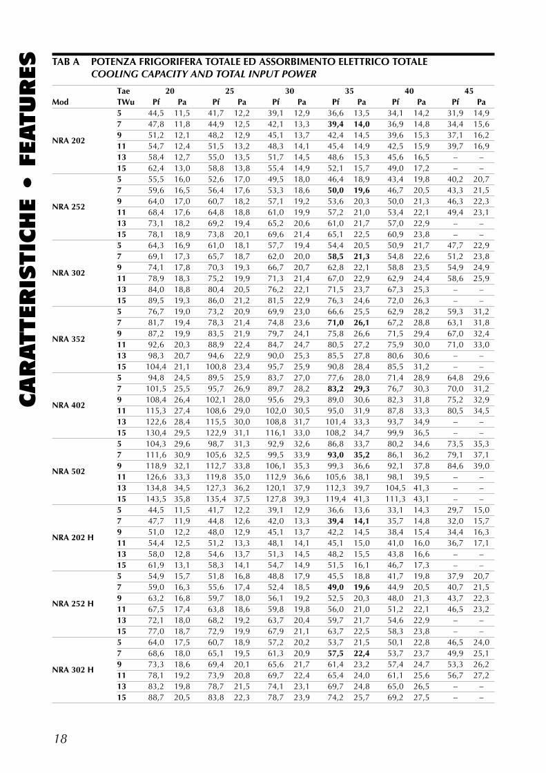
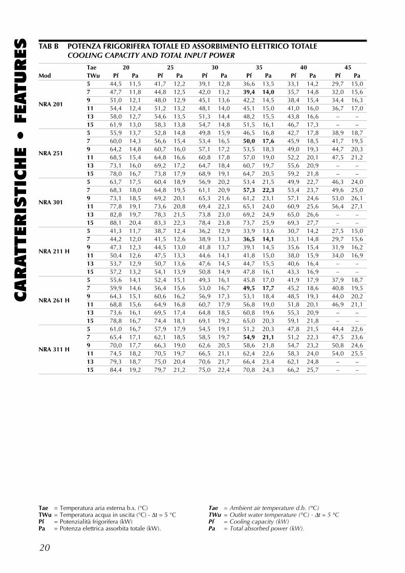
FEATURES TAB A POTENZA FRIGORIFERA TOTALE ED ASSORBIMENTO ELETTRICO TOTALE
COOLING CAPACITY AND TOTAL INPUT POWER
Tae 20 25 30 35 40 45Mod TWu Pf Pa Pf Pa Pf Pa Pf Pa Pf Pa Pf Pa
5 44,5 11,5 41,7 12,2 39,1 12,9 36,6 13,5 34,1 14,2 31,9 14,97 47,8 11,8 44,9 12,5 42,1 13,3 39,4 14,0 36,9 14,8 34,4 15,6
NRA 2029 51,2 12,1 48,2 12,9 45,1 13,7 42,4 14,5 39,6 15,3 37,1 16,211 54,7 12,4 51,5 13,2 48,3 14,1 45,4 14,9 42,5 15,9 39,7 16,913 58,4 12,7 55,0 13,5 51,7 14,5 48,6 15,3 45,6 16,5 – –15 62,4 13,0 58,8 13,8 55,4 14,9 52,1 15,7 49,0 17,2 – –5 55,5 16,0 52,6 17,0 49,5 18,0 46,4 18,9 43,4 19,8 40,2 20,77 59,6 16,5 56,4 17,6 53,3 18,6 50,0 19,6 46,7 20,5 43,3 21,5
NRA 2529 64,0 17,0 60,7 18,2 57,1 19,2 53,6 20,3 50,0 21,3 46,3 22,311 68,4 17,6 64,8 18,8 61,0 19,9 57,2 21,0 53,4 22,1 49,4 23,113 73,1 18,2 69,2 19,4 65,2 20,6 61,0 21,7 57,0 22,9 – –15 78,1 18,9 73,8 20,1 69,6 21,4 65,1 22,5 60,9 23,8 – –5 64,3 16,9 61,0 18,1 57,7 19,4 54,4 20,5 50,9 21,7 47,7 22,97 69,1 17,3 65,7 18,7 62,0 20,0 58,5 21,3 54,8 22,6 51,2 23,8
NRA 3029 74,1 17,8 70,3 19,3 66,7 20,7 62,8 22,1 58,8 23,5 54,9 24,911 78,9 18,3 75,2 19,9 71,3 21,4 67,0 22,9 62,9 24,4 58,6 25,913 84,0 18,8 80,4 20,5 76,2 22,1 71,5 23,7 67,3 25,3 – –15 89,5 19,3 86,0 21,2 81,5 22,9 76,3 24,6 72,0 26,3 – –5 76,7 19,0 73,2 20,9 69,9 23,0 66,6 25,5 62,9 28,2 59,3 31,27 81,7 19,4 78,3 21,4 74,8 23,6 71,0 26,1 67,2 28,8 63,1 31,8
NRA 3529 87,2 19,9 83,5 21,9 79,7 24,1 75,8 26,6 71,5 29,4 67,0 32,411 92,6 20,3 88,9 22,4 84,7 24,7 80,5 27,2 75,9 30,0 71,0 33,013 98,3 20,7 94,6 22,9 90,0 25,3 85,5 27,8 80,6 30,6 – –15 104,4 21,1 100,8 23,4 95,7 25,9 90,8 28,4 85,5 31,2 – –5 94,8 24,5 89,5 25,9 83,7 27,0 77,6 28,0 71,4 28,9 64,8 29,67 101,5 25,5 95,7 26,9 89,7 28,2 83,2 29,3 76,7 30,3 70,0 31,2
NRA 4029 108,4 26,4 102,1 28,0 95,6 29,3 89,0 30,6 82,3 31,8 75,2 32,911 115,3 27,4 108,6 29,0 102,0 30,5 95,0 31,9 87,8 33,3 80,5 34,513 122,6 28,4 115,5 30,0 108,8 31,7 101,4 33,3 93,7 34,9 – –15 130,4 29,5 122,9 31,1 116,1 33,0 108,2 34,7 99,9 36,5 – –5 104,3 29,6 98,7 31,3 92,9 32,6 86,8 33,7 80,2 34,6 73,5 35,37 111,6 30,9 105,6 32,5 99,5 33,9 93,0 35,2 86,1 36,2 79,1 37,1
NRA 5029 118,9 32,1 112,7 33,8 106,1 35,3 99,3 36,6 92,1 37,8 84,6 39,011 126,6 33,3 119,8 35,0 112,9 36,6 105,6 38,1 98,1 39,5 – –13 134,8 34,5 127,3 36,2 120,1 37,9 112,3 39,7 104,5 41,3 – –15 143,5 35,8 135,4 37,5 127,8 39,3 119,4 41,3 111,3 43,1 – –5 44,5 11,5 41,7 12,2 39,1 12,9 36,6 13,6 33,1 14,3 29,7 15,07 47,7 11,9 44,8 12,6 42,0 13,3 39,4 14,1 35,7 14,8 32,0 15,7
NRA 202 H9 51,0 12,2 48,0 12,9 45,1 13,7 42,2 14,5 38,4 15,4 34,4 16,311 54,4 12,5 51,2 13,3 48,1 14,1 45,1 15,0 41,0 16,0 36,7 17,113 58,0 12,8 54,6 13,7 51,3 14,5 48,2 15,5 43,8 16,6 – –15 61,9 13,1 58,3 14,1 54,7 14,9 51,5 16,1 46,7 17,3 – –5 54,9 15,7 51,8 16,8 48,8 17,9 45,5 18,8 41,7 19,8 37,9 20,77 59,0 16,3 55,6 17,4 52,4 18,5 49,0 19,6 44,9 20,5 40,7 21,5
NRA 252 H9 63,2 16,8 59,7 18,0 56,1 19,2 52,5 20,3 48,0 21,3 43,7 22,311 67,5 17,4 63,8 18,6 59,8 19,8 56,0 21,0 51,2 22,1 46,5 23,213 72,1 18,0 68,2 19,2 63,7 20,4 59,7 21,7 54,6 22,9 – –15 77,0 18,7 72,9 19,9 67,9 21,1 63,7 22,5 58,3 23,8 – –5 64,0 17,5 60,7 18,9 57,2 20,2 53,7 21,5 50,1 22,8 46,5 24,07 68,6 18,0 65,1 19,5 61,3 20,9 57,5 22,4 53,7 23,7 49,9 25,1
NRA 302 H9 73,3 18,6 69,4 20,1 65,6 21,7 61,4 23,2 57,4 24,7 53,3 26,211 78,1 19,2 73,9 20,8 69,7 22,4 65,4 24,0 61,1 25,6 56,7 27,213 83,2 19,8 78,7 21,5 74,1 23,1 69,7 24,8 65,0 26,5 – –15 88,7 20,5 83,8 22,3 78,7 23,9 74,2 25,7 69,2 27,5 – –
19
CARATTERIS
TIC
HE •
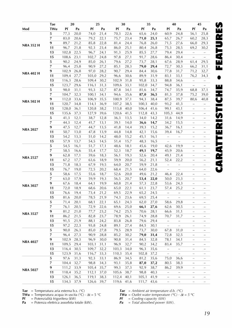
FEATURESTae 20 25 30 35 40 45
Mod TWu Pf Pa Pf Pa Pf Pa Pf Pa Pf Pa Pf Pa5 77,3 20,0 74,0 21,4 70,3 22,6 65,6 24,0 60,9 24,8 56,1 25,87 83,0 20,6 79,2 22,1 75,7 23,4 71,0 25,1 65,7 26,7 60,2 28,3
NRA 352 H9 89,7 21,2 85,8 22,8 81,4 24,4 76,8 26,0 71,5 27,6 66,0 29,311 96,7 21,8 92,3 23,4 86,0 25,1 80,4 26,8 75,3 28,5 69,2 30,213 102,8 22,5 96,7 24,1 91,3 25,9 85,5 27,7 79,4 29,4 – –15 108,6 23,1 102,7 24,8 97,8 27,1 91,7 28,6 86,4 30,4 – –5 90,2 24,9 85,0 26,1 79,6 27,2 73,7 28,1 67,6 28,9 61,4 29,57 96,4 25,8 90,9 27,2 85,1 28,3 79,0 29,4 72,7 30,3 66,2 31,1
NRA 402 H9 102,9 26,8 97,0 28,2 90,7 29,4 84,4 30,6 77,8 31,7 71,2 32,711 109,4 27,7 103,0 29,2 96,6 30,6 89,9 31,9 83,1 33,1 76,2 34,313 116,3 28,6 109,4 30,2 102,9 31,8 95,8 33,3 88,8 34,6 – –15 123,7 29,6 116,1 31,3 109,6 33,1 102,0 34,7 94,8 36,1 – –5 98,0 31,1 93,3 32,7 87,8 34,1 81,6 34,7 74,7 35,9 68,8 37,17 104,7 32,3 100,1 34,1 94,6 35,6 87,0 36,5 81,3 37,8 75,2 39,0
NRA 502 H9 112,0 33,6 106,9 35,5 100,9 37,1 94,3 38,4 87,5 39,7 80,6 40,811 120,7 34,8 114,1 36,9 107,2 38,5 100,3 40,0 93,2 41,3 – –13 128,0 36,1 120,8 38,2 113,8 40,0 106,4 41,6 99,1 43,1 – –15 135,6 37,3 127,9 39,6 120,6 41,5 112,8 43,3 105,3 44,9 – –5 41,3 12,1 38,7 12,8 36,3 13,5 34,0 14,2 31,6 14,9 – –7 44,3 12,4 41,7 13,1 39,1 14,0 36,6 14,7 34,2 15,5 – –
NRA 20279 47,5 12,7 44,7 13,5 41,8 14,4 39,3 15,2 36,7 16,1 – –11 50,7 13,0 47,8 13,9 44,8 14,8 42,1 15,6 39,4 16,7 – –13 54,2 13,3 51,0 14,2 48,0 15,2 45,1 16,1 – – – –15 57,9 13,7 54,5 14,5 51,4 15,7 48,3 16,5 – – – –5 54,5 16,1 51,7 17,1 48,6 18,1 45,6 19,0 42,6 19,9 – –7 58,5 16,6 55,4 17,7 52,3 18,7 49,1 19,7 45,9 20,6 – –
NRA 25279 62,8 17,1 59,6 18,3 56,1 19,3 52,6 20,4 49,1 21,4 – –11 67,2 17,7 63,6 18,9 59,9 20,0 56,2 21,1 52,4 22,2 – –13 71,8 18,3 67,9 19,5 64,0 20,7 59,9 21,8 – – – –15 76,7 19,0 72,5 20,2 68,4 21,5 64,0 22,6 – – – –5 58,6 17,5 55,6 18,7 52,6 20,0 49,6 21,2 46,4 22,4 – –7 63,0 17,9 59,9 19,3 56,5 20,7 53,4 22,0 50,0 23,3 – –
NRA 30279 67,6 18,4 64,1 19,9 60,8 21,4 57,3 22,8 53,6 24,3 – –11 72,0 18,9 68,6 20,6 65,0 22,1 61,1 23,7 57,4 25,2 – –13 76,6 19,4 73,4 21,2 69,5 22,9 65,2 24,5 – – – –15 81,6 20,0 78,5 21,9 74,3 23,6 69,5 25,4 – – – –5 71,4 20,1 68,1 22,1 65,1 24,3 62,0 27,0 58,6 29,8 – –7 76,1 20,5 72,9 22,6 69,6 25,0 66,1 27,6 62,6 30,5 – –
NRA 35279 81,2 21,0 77,7 23,2 74,2 25,5 70,6 28,1 66,6 31,1 – –11 86,2 21,5 82,8 23,7 78,9 26,1 74,9 28,8 70,7 31,7 – –13 91,5 21,9 88,1 24,2 83,8 26,8 79,6 29,4 – – – –15 97,2 22,3 93,8 24,8 89,1 27,4 84,5 30,1 – – – –5 90,0 26,3 85,0 27,8 79,5 28,9 73,7 30,0 67,8 31,0 – –7 96,4 27,3 90,9 28,8 85,2 30,2 79,0 31,4 72,8 32,5 – –
NRA 40279 102,9 28,3 96,9 30,0 90,8 31,4 84,5 32,8 78,1 34,1 – –11 109,5 29,4 103,1 31,1 96,9 32,7 90,2 34,2 83,4 35,7 – –13 116,4 30,5 109,7 32,2 103,3 34,0 96,3 35,6 – – – –15 123,9 31,6 116,7 33,3 110,3 35,4 102,8 37,2 – – – –5 97,6 31,3 92,3 33,1 86,9 34,5 81,2 35,6 75,0 36,6 – –7 104,4 32,7 98,8 34,3 93,1 35,8 87,0 37,2 80,5 38,3 – –
NRA 50279 111,2 33,9 105,4 35,7 99,3 37,3 92,9 38,7 86,2 39,9 – –11 118,4 35,2 112,1 37,0 105,6 38,7 98,8 40,3 – – – –13 126,1 36,5 119,1 38,3 112,4 40,1 105,1 41,9 – – – –15 134,3 37,9 126,6 39,7 119,6 41,6 111,7 43,6 – – – –
Tae = Temperatura aria esterna b.s. (°C)TWu = Temperatura acqua in uscita (°C) - ∆t = 5 °CPf = Potenzialità frigorifera (kW)Pa = Potenza elettrica assorbita totale (kW).
Tae = Ambient air temperature d.b. (°C)TWu = Outlet water temperature (°C) - ∆t = 5 °CPf = Cooling capacity (kW)Pa = Total absorbed power (kW).
20
CARATTERIS
TIC
HE •
FEATURES TAB B POTENZA FRIGORIFERA TOTALE ED ASSORBIMENTO ELETTRICO TOTALE
COOLING CAPACITY AND TOTAL INPUT POWER
Tae = Temperatura aria esterna b.s. (°C)TWu = Temperatura acqua in uscita (°C) - ∆t = 5 °CPf = Potenzialità frigorifera (kW)Pa = Potenza elettrica assorbita totale (kW).
Tae = Ambient air temperature d.b. (°C)TWu = Outlet water temperature (°C) - ∆t = 5 °CPf = Cooling capacity (kW)Pa = Total absorbed power (kW).
Tae 20 25 30 35 40 45Mod TWu Pf Pa Pf Pa Pf Pa Pf Pa Pf Pa Pf Pa
5 44,5 11,5 41,7 12,2 39,1 12,8 36,6 13,5 33,1 14,2 29,7 15,07 47,7 11,8 44,8 12,5 42,0 13,2 39,4 14,0 35,7 14,8 32,0 15,6
NRA 2019 51,0 12,1 48,0 12,9 45,1 13,6 42,2 14,5 38,4 15,4 34,4 16,311 54,4 12,4 51,2 13,2 48,1 14,0 45,1 15,0 41,0 16,0 36,7 17,013 58,0 12,7 54,6 13,5 51,3 14,4 48,2 15,5 43,8 16,6 – –15 61,9 13,0 58,3 13,8 54,7 14,8 51,5 16,1 46,7 17,3 – –5 55,9 13,7 52,8 14,8 49,8 15,9 46,5 16,8 42,7 17,8 38,9 18,77 60,0 14,3 56,6 15,4 53,4 16,5 50,0 17,6 45,9 18,5 41,7 19,5
NRA 2519 64,2 14,8 60,7 16,0 57,1 17,2 53,5 18,3 49,0 19,3 44,7 20,311 68,5 15,4 64,8 16,6 60,8 17,8 57,0 19,0 52,2 20,1 47,5 21,213 73,1 16,0 69,2 17,2 64,7 18,4 60,7 19,7 55,6 20,9 – –15 78,0 16,7 73,8 17,9 68,9 19,1 64,7 20,5 59,2 21,8 – –5 63,7 17,5 60,4 18,9 56,9 20,2 53,4 21,5 49,9 22,7 46,3 24,07 68,3 18,0 64,8 19,5 61,1 20,9 57,3 22,3 53,4 23,7 49,6 25,0
NRA 3019 73,1 18,5 69,2 20,1 65,3 21,6 61,2 23,1 57,1 24,6 53,0 26,111 77,8 19,1 73,6 20,8 69,4 22,3 65,1 24,0 60,9 25,6 56,4 27,113 82,8 19,7 78,3 21,5 73,8 23,0 69,2 24,9 65,0 26,6 – –15 88,1 20,4 83,3 22,3 78,4 23,8 73,7 25,9 69,3 27,7 – –5 41,3 11,7 38,7 12,4 36,2 12,9 33,9 13,6 30,7 14,2 27,5 15,07 44,2 12,0 41,5 12,6 38,9 13,3 36,5 14,1 33,1 14,8 29,7 15,6
NRA 211 H9 47,3 12,3 44,5 13,0 41,8 13,7 39,1 14,5 35,6 15,4 31,9 16,211 50,4 12,6 47,5 13,3 44,6 14,1 41,8 15,0 38,0 15,9 34,0 16,913 53,7 12,9 50,7 13,6 47,6 14,5 44,7 15,5 40,6 16,4 – –15 57,2 13,2 54,1 13,9 50,8 14,9 47,8 16,1 43,3 16,9 – –5 55,6 14,1 52,4 15,1 49,3 16,1 45,8 17,0 41,9 17,9 37,9 18,77 59,9 14,6 56,4 15,6 53,0 16,7 49,5 17,7 45,2 18,6 40,8 19,5
NRA 261 H9 64,3 15,1 60,6 16,2 56,9 17,3 53,1 18,4 48,5 19,3 44,0 20,211 68,8 15,6 64,9 16,8 60,7 17,9 56,8 19,0 51,8 20,1 46,9 21,113 73,6 16,1 69,5 17,4 64,8 18,5 60,8 19,6 55,3 20,9 – –15 78,8 16,7 74,4 18,1 69,1 19,2 65,0 20,3 59,1 21,8 – –5 61,0 16,7 57,9 17,9 54,5 19,1 51,2 20,3 47,8 21,5 44,4 22,67 65,4 17,1 62,1 18,5 58,5 19,7 54,9 21,1 51,2 22,3 47,5 23,6
NRA 311 H9 70,0 17,7 66,3 19,0 62,6 20,5 58,6 21,8 54,7 23,2 50,8 24,611 74,5 18,2 70,5 19,7 66,5 21,1 62,4 22,6 58,3 24,0 54,0 25,513 79,3 18,7 75,0 20,4 70,6 21,7 66,4 23,4 62,1 24,8 – –15 84,4 19,2 79,7 21,2 75,0 22,4 70,8 24,3 66,2 25,7 – –
21
CARATTERIS
TIC
HE •
FEATURES
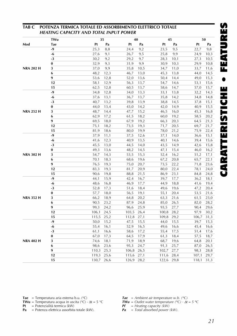
Tae = Temperatura aria esterna b.u. (°C)TWu = Temperatura acqua in uscita (°C) - ∆t = 5 °CPt = Potenzialità termica (kW)Pa = Potenza elettrica assorbita totale (kW).
Tae = Ambient air temperature w.b. (°C)TWu = Outlet water temperature (°C) - ∆t = 5 °CPf = Heating capacity (kW)Pa = Total absorbed power (kW).
TWu 35 40 45 50Mod Tae Pt Pa Pt Pa Pt Pa Pt Pa
-9 25,3 8,8 24,4 9,2 23,5 9,5 22,7 9,8-6 27,6 9,1 26,7 9,5 25,8 9,9 24,9 10,3-3 30,2 9,2 29,2 9,7 28,3 10,1 27,3 10,50 32,9 9,3 31,9 9,9 30,9 10,3 29,9 10,8
NRA 202 H 3 37,0 9,9 35,8 10,5 34,7 11,0 33,7 11,66 48,2 12,3 46,7 13,0 45,3 13,8 44,0 14,59 53,6 12,8 52,0 13,6 50,4 14,4 49,0 15,312 58,1 12,9 56,3 13,7 54,7 14,6 53,1 15,615 62,5 12,8 60,5 13,7 58,6 14,7 57,0 15,7-9 34,8 12,8 34,0 13,3 33,1 13,8 32,2 14,3-6 37,6 13,1 36,7 13,7 35,8 14,2 34,8 14,8-3 40,7 13,2 39,8 13,9 38,8 14,5 37,8 15,10 44,0 13,4 43,0 14,2 42,0 14,9 40,9 15,5
NRA 252 H 3 48,7 14,4 47,7 15,2 46,5 16,0 45,3 16,86 62,9 17,2 61,5 18,2 60,0 19,2 58,5 20,29 69,5 18,0 67,9 19,2 66,3 20,3 64,5 21,312 75,1 18,2 73,5 19,3 71,7 20,5 69,7 21,715 81,9 18,6 80,0 19,9 78,0 21,2 75,9 22,4-9 37,9 11,1 37,5 12,6 37,1 14,0 36,6 15,1-6 41,6 12,3 40,9 13,5 40,1 14,6 39,4 15,6-3 45,5 13,0 44,5 14,0 43,5 14,9 42,6 15,80 49,3 13,6 48,2 14,5 47,1 15,4 46,0 16,2
NRA 302 H 3 54,7 14,3 53,5 15,3 52,4 16,2 51,2 17,16 70,1 18,3 68,6 19,6 67,2 20,8 65,7 22,19 76,5 19,3 75,0 20,7 73,5 22,2 71,8 23,612 83,3 19,3 81,7 20,9 80,0 22,4 78,1 24,015 90,6 19,8 88,8 21,5 86,9 23,1 84,8 24,8-9 44,1 15,9 42,4 16,7 39,7 17,7 36,2 18,1-6 48,6 16,8 46,9 17,7 44,9 18,8 41,6 19,4-3 52,8 17,3 51,6 18,4 49,6 19,6 47,2 20,40 57,7 18,0 56,5 19,1 55,1 20,4 53,5 21,6
NRA 352 H 3 66,2 18,9 64,8 20,2 63,3 21,6 61,5 23,06 90,5 23,2 87,9 24,8 85,0 26,5 82,0 28,29 99,3 24,2 96,6 25,9 93,5 27,7 90,4 29,612 106,1 24,5 103,5 26,4 100,8 28,2 97,9 30,215 115,5 25,2 112,8 27,1 109,8 29,2 106,7 31,3-9 50,0 15,2 47,5 15,5 44,0 15,5 39,7 15,3-6 55,4 16,1 52,9 16,5 49,6 16,6 45,4 16,6-3 61,1 16,6 58,6 17,2 55,4 17,5 51,4 17,60 67,0 17,3 64,5 17,9 61,3 18,4 57,5 18,7
NRA 402 H 3 74,6 18,1 71,9 18,9 68,7 19,6 64,8 20,16 98,6 23,6 95,3 24,7 91,3 25,7 87,0 26,59 110,3 25,3 106,8 26,5 102,7 27,7 98,3 28,812 119,3 25,6 115,6 27,1 111,6 28,4 107,1 29,715 130,7 26,6 126,9 28,2 122,6 29,8 118,1 31,3
TAB C POTENZA TERMICA TOTALE ED ASSORBIMENTO ELETTRICO TOTALEHEATING CAPACITY AND TOTAL INPUT POWER
22
CARATTERIS
TIC
HE •
FEATURES
TWu 35 40 45 50Mod Tae Pt Pa Pt Pa Pt Pa Pt Pa
-9 58,7 20,9 56,2 21,4 53,1 21,7 46,8 21,9-6 65,1 22,0 62,6 22,7 58,4 23,1 53,0 23,5-3 71,1 22,3 67,6 23,1 64,0 23,7 59,4 24,10 77,0 22,6 72,6 23,5 69,3 24,3 66,0 24,8
NRA 502 H 3 85,9 24,3 81,0 25,4 77,7 26,3 74,0 27,16 112,2 30,2 108,6 31,6 104,5 32,9 100,0 34,09 124,3 32,0 120,5 33,5 116,2 35,0 111,6 36,412 135,5 32,9 131,4 34,7 127,0 36,3 122,2 37,915 148,6 34,3 144,3 36,2 139,6 38,1 134,5 39,9-9 25,0 8,4 24,1 8,8 23,2 9,1 22,5 9,4-6 27,3 8,7 26,4 9,1 25,5 9,5 24,6 9,9-3 29,9 8,8 28,9 9,3 28,0 9,7 27,0 10,10 32,5 8,9 31,5 9,5 30,6 9,9 29,6 10,4
NRA 211 H 3 36,6 9,5 35,4 10,1 34,3 10,6 33,3 11,26 47,7 11,9 46,2 12,5 44,8 13,3 43,5 14,09 53,0 12,3 51,4 13,1 49,8 13,9 48,5 14,812 57,5 12,4 55,7 13,2 54,1 14,1 52,5 15,115 61,8 12,3 59,8 13,2 58,0 14,2 56,4 15,2-9 29,2 9,8 28,5 10,3 27,6 10,8 26,8 11,3-6 31,8 10,1 31,0 10,7 30,1 11,2 29,2 11,8-3 34,7 10,2 33,9 10,9 32,9 11,5 32,0 12,10 37,8 10,4 36,9 11,2 35,9 11,9 34,9 12,5
NRA 261 H 3 42,2 11,4 41,2 12,2 40,1 13,0 39,0 13,76 55,4 14,1 54,1 15,1 52,7 16,1 51,3 17,19 61,6 14,9 60,1 16,1 58,6 17,2 56,9 18,112 66,8 15,1 65,3 16,2 63,6 17,4 61,8 18,515 73,1 15,5 71,4 16,8 69,5 18,0 67,5 19,2-9 34,9 9,7 34,5 11,1 34,1 12,3 33,6 13,3-6 38,4 10,8 37,7 11,9 37,0 12,8 36,3 13,7-3 42,2 11,5 41,2 12,4 40,3 13,2 39,4 13,90 45,8 11,9 44,8 12,8 43,7 13,5 42,7 14,3
NRA 311 H 3 51,0 12,6 49,9 13,5 48,8 14,3 47,7 15,16 65,9 16,2 64,4 17,3 63,1 18,4 61,6 19,59 72,0 17,1 70,6 18,3 69,1 19,6 67,5 20,912 78,6 17,1 77,0 18,4 75,4 19,8 73,6 21,215 85,6 17,5 83,9 19,0 82,0 20,5 80,0 21,9
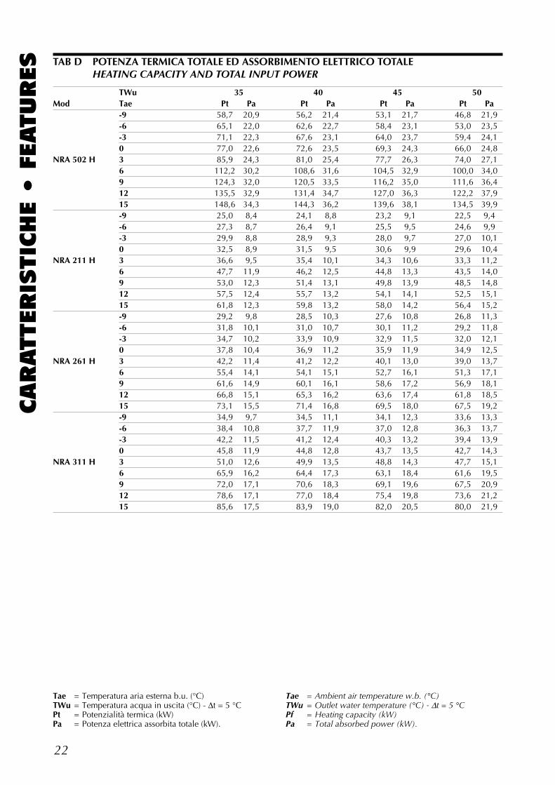
Tae = Temperatura aria esterna b.u. (°C)TWu = Temperatura acqua in uscita (°C) - ∆t = 5 °CPt = Potenzialità termica (kW)Pa = Potenza elettrica assorbita totale (kW).
Tae = Ambient air temperature w.b. (°C)TWu = Outlet water temperature (°C) - ∆t = 5 °CPf = Heating capacity (kW)Pa = Total absorbed power (kW).
TAB D POTENZA TERMICA TOTALE ED ASSORBIMENTO ELETTRICO TOTALEHEATING CAPACITY AND TOTAL INPUT POWER
23
CARATTERIS
TIC
HE •
FEATURES
0 2 4 6 8 10 12 14 m3/h0
10
20
30
40
50
60
kPa 70
A B
C
0
10
20
30
40
50
60
70
80
90
100
kPa 110
0 5 10 15 20 25 m3/h
AB
CD E
Portata acqua • Water flow
Portata acqua • Water flow
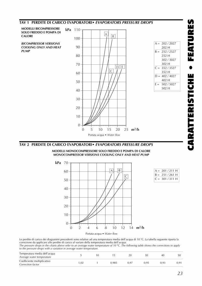
Le perdite di carico dei diagrammi precedenti sono relative ad una temperatura media dell’acqua di 10 °C. La tabella seguente riporta lacorrezione da applicare alle perdite di carico al variare della temperatura media dell’acqua.The pressure drops in the charts above refer to an average water temperature of 10 °C. The following table shows the corrections to applyto the pressure drops with a variation in average water temperature.
Temperatura media dell’acqua5 10 15 20 30 40 50
Average water temperature
Coefficiente moltiplicativo1,02 1 0,985 0,97 0,95 0,93 0,91
Correction factor
A = 202 / 2027202 H
B = 252 / 2527252 H302 / 3027302 H
C = 352 / 3527352 H
D = 402 / 4027402 H
E = 502 / 5027502 H
A = 201 / 211 HB = 251 / 261 HC = 301 / 311 H
MODELLI BICOMPRESSORESOLO FREDDO E POMPA DICALORE
BICOMPRESSOR VERSIONSCOOLING ONLY AND HEATPUMP
MODELLI MONOCOMPRESSORE SOLO FREDDO E POMPA DI CALOREMONOCOMPRESSOR VERSIONS COOLING ONLY AND HEAT PUMP
TAV 1 PERDITE DI CARICO EVAPORATORI• EVAPORATORS PRESSURE DROPS
TAV 2 PERDITE DI CARICO EVAPORATORI• EVAPORATORS PRESSURE DROPS
24
CARATTERIS
TIC
HE •
FEATURES
-10
-5
15
20
25
30
35
40
45
50
-6 -5 2 3 4 5 6 7 8 9 10
NRA 502
15
20
25
30
35
40
45
50
55
60
-15 -10 -5 0 5 10 15 20 25
SOLO FREDDO R22R22 COOLING ONLY
SOLO FREDDO R407CR407C COOLING ONLY
POMPA DI CALORE R22R22 HEAT PUMP MODELS
Temperatura acqua prodotta °C • Processed water temperatur °C
Tem
p. a
ria
este
rna
b.s.
°C
A
mbi
ent a
ir te
mp.
d.b
. °C
Temp. aria esterna b.s. °C • Ambient air temp. d.b. °C
Tem
pera
tura
acq
ua p
rodo
tta °
C
Proc
esse
d w
ater
tem
pera
tur
°C
Funzionamento con DCPXOperation with DCPX
Funzionamento standardStandard operation
Funzionamento conacqua glicolataOperation with gly-cole mix Funzionamento standard
Standard operation
Acqua glicolata +DCPXGlycole mix +DCPX
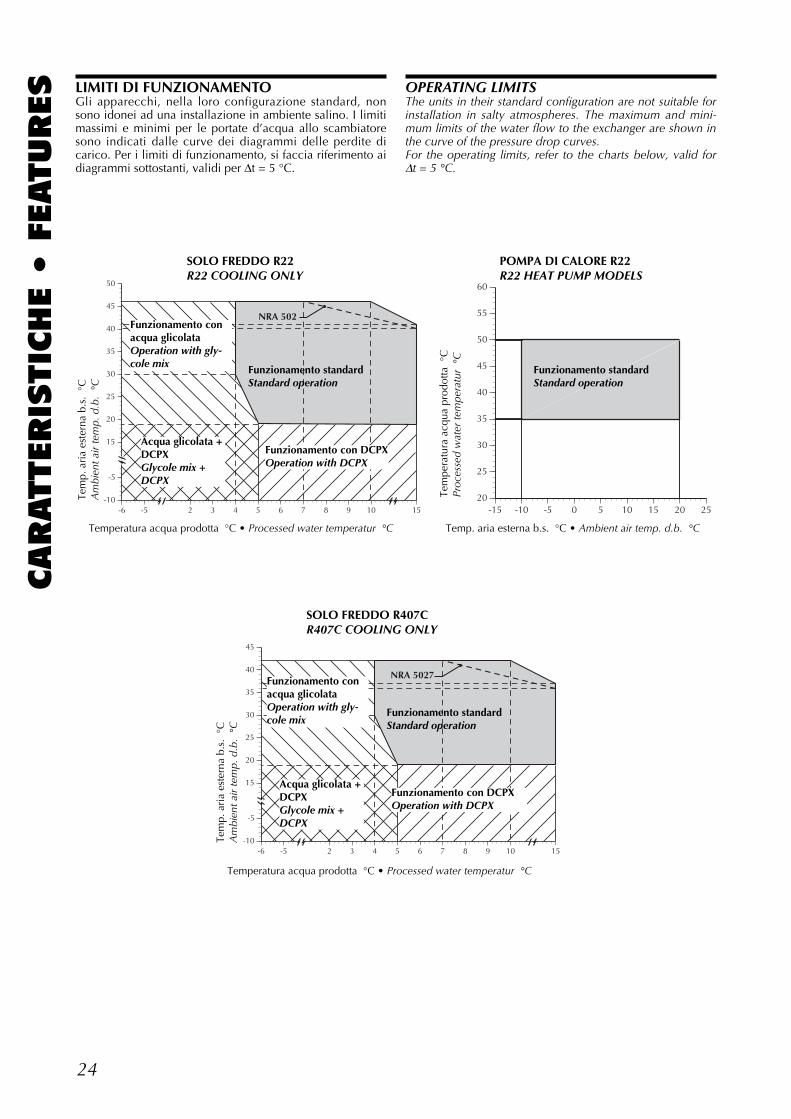
LIMITI DI FUNZIONAMENTOGli apparecchi, nella loro configurazione standard, nonsono idonei ad una installazione in ambiente salino. I limitimassimi e minimi per le portate d’acqua allo scambiatoresono indicati dalle curve dei diagrammi delle perdite dicarico. Per i limiti di funzionamento, si faccia riferimento aidiagrammi sottostanti, validi per ∆t = 5 °C.
OPERATING LIMITSThe units in their standard configuration are not suitable forinstallation in salty atmospheres. The maximum and mini-mum limits of the water flow to the exchanger are shown inthe curve of the pressure drop curves.For the operating limits, refer to the charts below, valid for∆t = 5 °C.
-10
-5
15
20
25
30
35
40
45
-6 -5 2 3 4 5 6 7 8 9 10
NRA 5027
15
Temperatura acqua prodotta °C • Processed water temperatur °C
Tem
p. a
ria
este
rna
b.s.
°C
A
mbi
ent a
ir te
mp.
d.b
. °C
Funzionamento con DCPXOperation with DCPX
Funzionamento standardStandard operation
Funzionamento conacqua glicolataOperation with gly-cole mix
Acqua glicolata +DCPXGlycole mix +DCPX
25
CARATTERIS
TIC
HE •
FEATURESCRITERI DI SCELTA PER NRA D
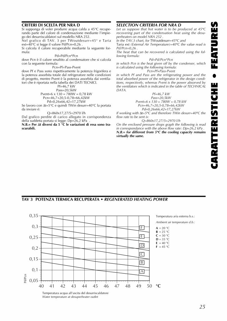
Si supponga di voler produrre acqua calda a 45°C recupe-rando parte del calore di condensazione mediante l’impie-go dei desurriscaldatori sul modello NRA 252.Nel grafico di TAV. 3 per TWoutdesurr=45° e Tariaext=40°C si legge il valore Pd/Pcn=0,26 .Si calcola il calore recuperabile mediante la seguente for-mula:
Pd=Pd/Pcn*Pcndove Pcn è il calore smaltito al condensatore che si calcolacon la seguente formula:
Pcn=Pf+Pass-Pventdove Pf e Pass sono rispettivamente la potenza frigorifera ela potenza assorbita totale dal refrigeratore nelle condizionidi progetto, mentre Pvent è la potenza assorbita dai ventila-tori che è riportata nella tabella dei DATI TECNICI.
Pf=46,7 kWPass=20,5kW
Pvent=6 x 130 = 780W = 0,78 kWPcn=46,7+20,5-0,78=66,42kW
Pd=0,26x66,42=17,27kWSe lavoro con ∆t=5°C e quindi TWin desurr=40°C la portatada inviare é:
Q=860x17,27/5=2970 l/hDal grafico perdite di carico allegato in corrispondenzadella suddetta portata si legge: Dp=26,2 kPa .N.B.= Per ∆∆t diversi da 5 °C le variazioni di resa sono tra-scurabili.
SELECTION CRITERIA FOR NRA DLet us suppose that hot water is to be produced at 45°Crecovering part of the condensation heat using the desu-perheaters on model NRA 252 . In the TAV.3 chart, for TWoutdesurr=45°C and Taria ext (External Air Temperature)=40°C the value read isPd/Pcn=0,26 .The heat that can be recovered is calculated using the fol-lowing formula:
Pd=Pd/Pcn*Pcnin which Pcn is the heat given off by the condenser, whichis calculated using the following formula:
Pcn=Pf+Pass-Pventin which Pf and Pass are the refrigerating power and thetotal absorbed power of the refrigerator in the design condi-tions, respectively, whereas Pvent is the power absorved bythe ventilators which is indicated in the table of TECHNICALDATA.
Pf=46,7 kWPass=20,5kW
Pvent=6 x 130 = 780W = 0,78 kWPcn=46,7+20,5-0,78=66,42kW
Pd=0,26x66,42=17,27kWIf working with ∆t=5°C and therefore TWin desurr=40°C theflow rate to be sent is:
Q=860x17,27/5=2970 l/hOn the enclosed pressure drops graph the following is readin correspondance with the above flow rate: Dp=26,2 kPa .N.B.= for different from 5°C the cooling capacity remainsvirtually the same.
TAV 3 POTENZA TERMICA RECUPERATA • REGENERATED HEATING POWER
0,05
0,1
0,15
0,2
0,25
0,3
0,35
40 41 42 43 44 45 46 47 48 49 50 °C
A
B
C
D
E
F
Temperatura acqua all’uscita del desurriscaldatoreWater temperature at desuperheater outlet
Temperatura aria esterna b.s.:
Ambient air temperature d.b.:
A = 20 °CB = 25 °CC = 30 °CD = 35 °CE = 40 °CF = 45 °C
Pd/P
cn
26
CARATTERIS
TIC
HE •
FEATURES
0
10
20
30
40
50
60
kPa 70
0 5 10 15 20 25 30 35 60 m3/h
B
40 45 50 55
A
Portata acqua • Water flow
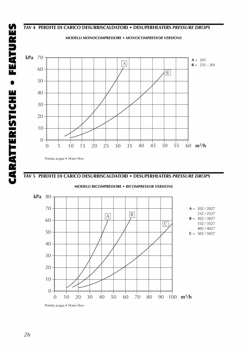
A = 201B = 251 - 301
MODELLI MONOCOMPRESSORE • MONOCOMPRESSOR VERSIONS
TAV 4 PERDITE DI CARICO DESURRISCALDATORI • DESUPERHEATERS PRESSURE DROPS
0
10
20
30
40
50
60
70
kPa 80
0 10 20 30 40 50 60 70 80 90 100 m3/h
C
A B
Portata acqua • Water flow
A = 202 / 2027252 / 2527
B = 302 / 3027352 / 3527402 / 4027
C = 502 / 5027
MODELLI BICOMPRESSORE • BICOMPRESSOR VERSIONS
TAV 5 PERDITE DI CARICO DESURRISCALDATORI • DESUPERHEATERS PRESSURE DROPS
27
CARATTERIS
TIC
HE •
FEATURES
0
10
20
30
40
50
60
70
80
90
kPa 100
0 5 10 15 20 25 30 35 40 45 l/h x 1000
2" 1/22"
Portata acqua • Water flow
Perd
ite d
i car
ico
• P
ress
ure
drop
s
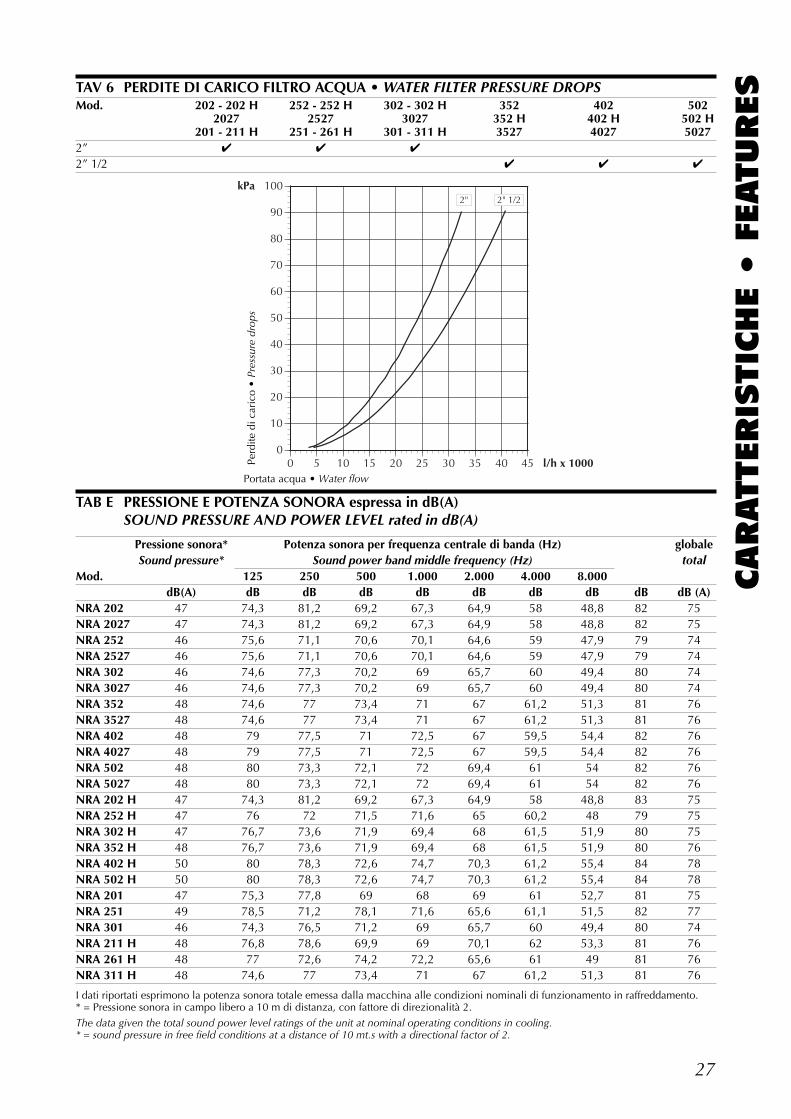
TAV 6 PERDITE DI CARICO FILTRO ACQUA • WATER FILTER PRESSURE DROPSMod. 202 - 202 H 252 - 252 H 302 - 302 H 352 402 502
2027 2527 3027 352 H 402 H 502 H201 - 211 H 251 - 261 H 301 - 311 H 3527 4027 5027
2” ✔ ✔ ✔
2” 1/2 ✔ ✔ ✔
TAB E PRESSIONE E POTENZA SONORA espressa in dB(A)SOUND PRESSURE AND POWER LEVEL rated in dB(A)
Pressione sonora* Potenza sonora per frequenza centrale di banda (Hz) globaleSound pressure* Sound power band middle frequency (Hz) total
Mod. 125 250 500 1.000 2.000 4.000 8.000dB(A) dB dB dB dB dB dB dB dB dB (A)
NRA 202 47 74,3 81,2 69,2 67,3 64,9 58 48,8 82 75NRA 2027 47 74,3 81,2 69,2 67,3 64,9 58 48,8 82 75NRA 252 46 75,6 71,1 70,6 70,1 64,6 59 47,9 79 74NRA 2527 46 75,6 71,1 70,6 70,1 64,6 59 47,9 79 74NRA 302 46 74,6 77,3 70,2 69 65,7 60 49,4 80 74NRA 3027 46 74,6 77,3 70,2 69 65,7 60 49,4 80 74NRA 352 48 74,6 77 73,4 71 67 61,2 51,3 81 76NRA 3527 48 74,6 77 73,4 71 67 61,2 51,3 81 76NRA 402 48 79 77,5 71 72,5 67 59,5 54,4 82 76NRA 4027 48 79 77,5 71 72,5 67 59,5 54,4 82 76NRA 502 48 80 73,3 72,1 72 69,4 61 54 82 76NRA 5027 48 80 73,3 72,1 72 69,4 61 54 82 76NRA 202 H 47 74,3 81,2 69,2 67,3 64,9 58 48,8 83 75NRA 252 H 47 76 72 71,5 71,6 65 60,2 48 79 75NRA 302 H 47 76,7 73,6 71,9 69,4 68 61,5 51,9 80 75NRA 352 H 48 76,7 73,6 71,9 69,4 68 61,5 51,9 80 76NRA 402 H 50 80 78,3 72,6 74,7 70,3 61,2 55,4 84 78NRA 502 H 50 80 78,3 72,6 74,7 70,3 61,2 55,4 84 78NRA 201 47 75,3 77,8 69 68 69 61 52,7 81 75NRA 251 49 78,5 71,2 78,1 71,6 65,6 61,1 51,5 82 77NRA 301 46 74,3 76,5 71,2 69 65,7 60 49,4 80 74NRA 211 H 48 76,8 78,6 69,9 69 70,1 62 53,3 81 76NRA 261 H 48 77 72,6 74,2 72,2 65,6 61 49 81 76NRA 311 H 48 74,6 77 73,4 71 67 61,2 51,3 81 76
I dati riportati esprimono la potenza sonora totale emessa dalla macchina alle condizioni nominali di funzionamento in raffreddamento.* = Pressione sonora in campo libero a 10 m di distanza, con fattore di direzionalità 2.The data given the total sound power level ratings of the unit at nominal operating conditions in cooling.* = sound pressure in free field conditions at a distance of 10 mt.s with a directional factor of 2.
28
CARATTERIS
TIC
HE •
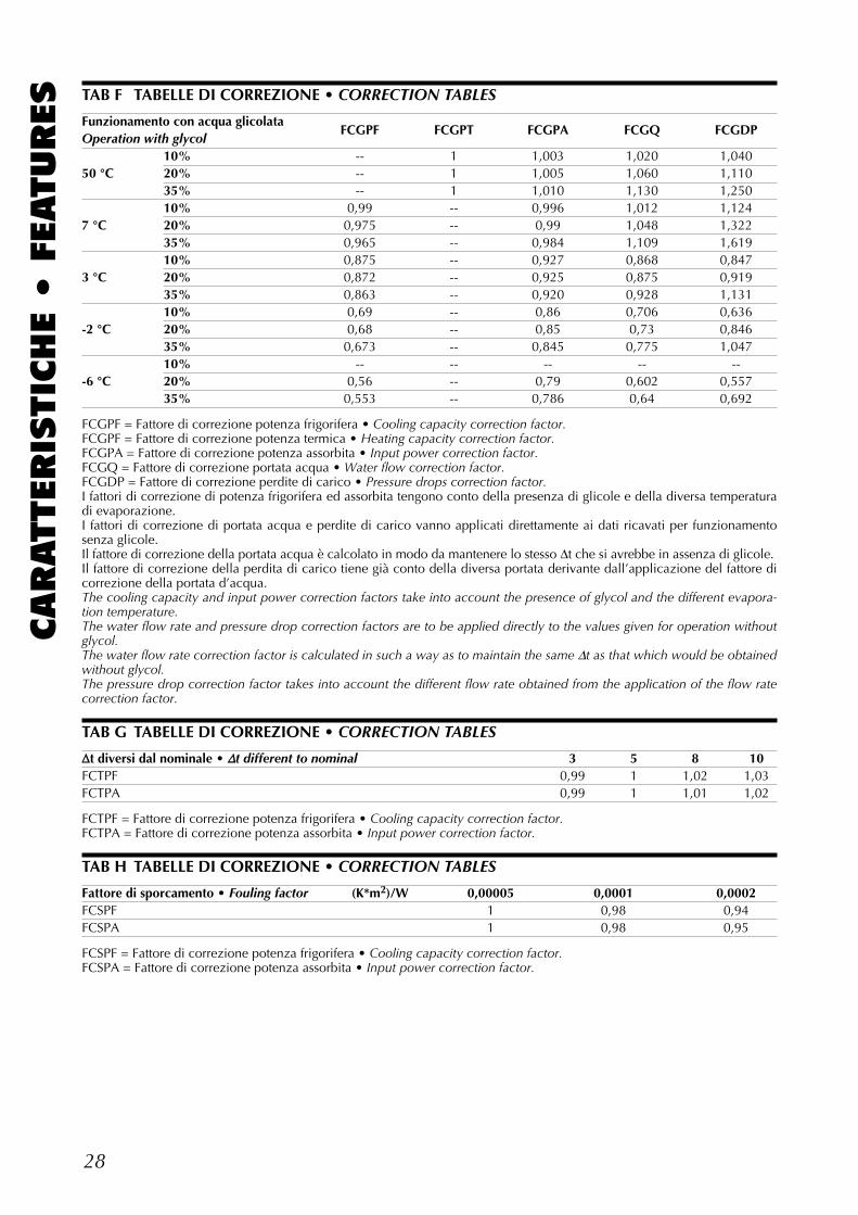
FEATURES TAB F TABELLE DI CORREZIONE • CORRECTION TABLES
Funzionamento con acqua glicolataFCGPF FCGPT FCGPA FCGQ FCGDP
Operation with glycol10% -- 1 1,003 1,020 1,040
50 °C 20% -- 1 1,005 1,060 1,11035% -- 1 1,010 1,130 1,25010% 0,99 -- 0,996 1,012 1,124
7 °C 20% 0,975 -- 0,99 1,048 1,32235% 0,965 -- 0,984 1,109 1,61910% 0,875 -- 0,927 0,868 0,847
3 °C 20% 0,872 -- 0,925 0,875 0,91935% 0,863 -- 0,920 0,928 1,13110% 0,69 -- 0,86 0,706 0,636
-2 °C 20% 0,68 -- 0,85 0,73 0,84635% 0,673 -- 0,845 0,775 1,04710% -- -- -- -- --
-6 °C 20% 0,56 -- 0,79 0,602 0,55735% 0,553 -- 0,786 0,64 0,692
FCGPF = Fattore di correzione potenza frigorifera • Cooling capacity correction factor.FCGPF = Fattore di correzione potenza termica • Heating capacity correction factor.FCGPA = Fattore di correzione potenza assorbita • Input power correction factor.FCGQ = Fattore di correzione portata acqua • Water flow correction factor.FCGDP = Fattore di correzione perdite di carico • Pressure drops correction factor.I fattori di correzione di potenza frigorifera ed assorbita tengono conto della presenza di glicole e della diversa temperaturadi evaporazione.I fattori di correzione di portata acqua e perdite di carico vanno applicati direttamente ai dati ricavati per funzionamentosenza glicole.Il fattore di correzione della portata acqua è calcolato in modo da mantenere lo stesso ∆t che si avrebbe in assenza di glicole.Il fattore di correzione della perdita di carico tiene già conto della diversa portata derivante dall’applicazione del fattore dicorrezione della portata d’acqua.The cooling capacity and input power correction factors take into account the presence of glycol and the different evapora-tion temperature.The water flow rate and pressure drop correction factors are to be applied directly to the values given for operation withoutglycol.The water flow rate correction factor is calculated in such a way as to maintain the same ∆t as that which would be obtainedwithout glycol.The pressure drop correction factor takes into account the different flow rate obtained from the application of the flow ratecorrection factor.
TAB G TABELLE DI CORREZIONE • CORRECTION TABLES
∆∆t diversi dal nominale • ∆∆t different to nominal 3 5 8 10FCTPF 0,99 1 1,02 1,03FCTPA 0,99 1 1,01 1,02
FCTPF = Fattore di correzione potenza frigorifera • Cooling capacity correction factor.FCTPA = Fattore di correzione potenza assorbita • Input power correction factor.
TAB H TABELLE DI CORREZIONE • CORRECTION TABLES
Fattore di sporcamento • Fouling factor (K*m2)/W 0,00005 0,0001 0,0002FCSPF 1 0,98 0,94FCSPA 1 0,98 0,95
FCSPF = Fattore di correzione potenza frigorifera • Cooling capacity correction factor.FCSPA = Fattore di correzione potenza assorbita • Input power correction factor.
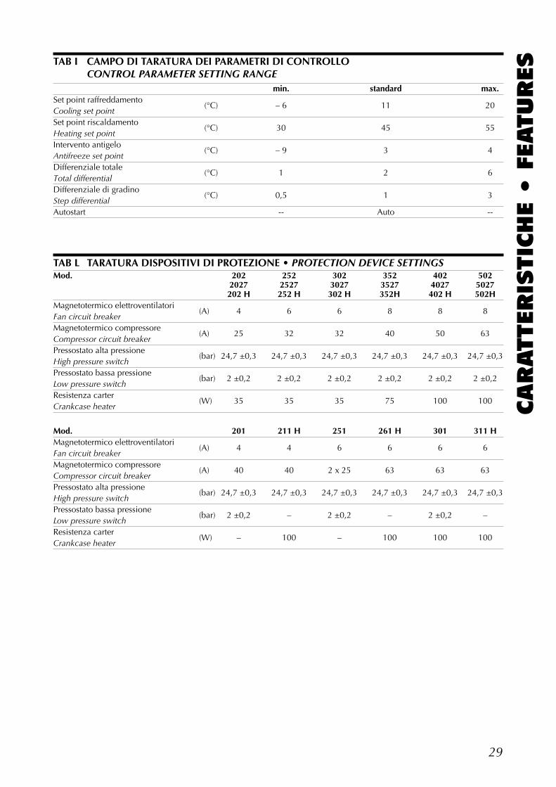
29
CARATTERIS
TIC
HE •
FEATURESTAB I CAMPO DI TARATURA DEI PARAMETRI DI CONTROLLO
CONTROL PARAMETER SETTING RANGEmin. standard max.
Set point raffreddamento(°C) – 6 11 20
Cooling set pointSet point riscaldamento
(°C) 30 45 55Heating set pointIntervento antigelo
(°C) – 9 3 4Antifreeze set pointDifferenziale totale
(°C) 1 2 6Total differentialDifferenziale di gradino
(°C) 0,5 1 3Step differentialAutostart -- Auto --
TAB L TARATURA DISPOSITIVI DI PROTEZIONE • PROTECTION DEVICE SETTINGSMod. 202 252 302 352 402 502
2027 2527 3027 3527 4027 5027202 H 252 H 302 H 352H 402 H 502H
Magnetotermico elettroventilatori(A) 4 6 6 8 8 8
Fan circuit breakerMagnetotermico compressore
(A) 25 32 32 40 50 63Compressor circuit breakerPressostato alta pressione
(bar) 24,7 ±0,3 24,7 ±0,3 24,7 ±0,3 24,7 ±0,3 24,7 ±0,3 24,7 ±0,3High pressure switchPressostato bassa pressione
(bar) 2 ±0,2 2 ±0,2 2 ±0,2 2 ±0,2 2 ±0,2 2 ±0,2Low pressure switchResistenza carter
(W) 35 35 35 75 100 100Crankcase heater
Mod. 201 211 H 251 261 H 301 311 HMagnetotermico elettroventilatori
(A) 4 4 6 6 6 6Fan circuit breakerMagnetotermico compressore
(A) 40 40 2 x 25 63 63 63Compressor circuit breakerPressostato alta pressione
(bar) 24,7 ±0,3 24,7 ±0,3 24,7 ±0,3 24,7 ±0,3 24,7 ±0,3 24,7 ±0,3High pressure switchPressostato bassa pressione
(bar) 2 ±0,2 – 2 ±0,2 – 2 ±0,2 –Low pressure switchResistenza carter
(W) – 100 – 100 100 100Crankcase heater
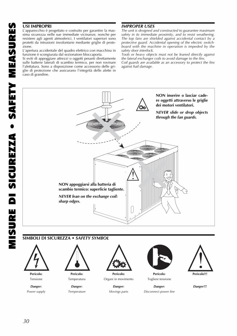
30
MIS
URE D
I SIC
UREZZA •
SAFE
TY M
EASURES
Pericolo: Pericolo: Pericolo: Pericolo: Pericolo!!!
Tensione Temperatura Organi in movimento Togliere tensione
Danger: Danger: Danger: Danger: Danger!!!
Power supply Temperature Movings parts Disconnect power line
SIMBOLI DI SICUREZZA • SAFETY SYMBOL
NON inserire o lasciar cade-re oggetti attraverso le grigliedei motori ventilatori.
NEVER slide or drop objectsthrough the fan guards.
NON appoggiarsi alla batteria discambio termico: superficie tagliente.
NEVER lean on the exchange coil:sharp edges.
USI IMPROPRIL'apparecchio è progettato e costruito per garantire la mas-sima sicurezza nelle sue immediate vicinanze, nonche perresistere agli agenti atmosferici. I ventilatori superiori sonoprotetti da intrusioni involontarie mediante griglie di prote-zione.L’apertura accidentale del quadro elettrico con macchina infunzione è scongiurata dal sezionatore bloccaporta.Si eviti di appoggiare attrezzi o oggetti pesanti direttamentesulle batterie laterali di scambio termico, per non rovinarel'alettatura. Sono a disposizione come accessorio delle gri-glie di protezione che assicurano l'integrità delle alette incaso di grandine.
IMPROPER USESThe unit is designed and constructed to guarantee maximumsafety in its immediate proximity, and to resist weathering.The top fans are shielded against accidental contact by aprotective guard. Accidental opening of the electric switch-board with the machine in operation is impeded by thesafety door interlock.Tools or heavy objects must not be leaned directly againstthe lateral exchanger coils to avoid damage to the fins.Coil guards are available as an accessory to protect the finsagainst hail damage.
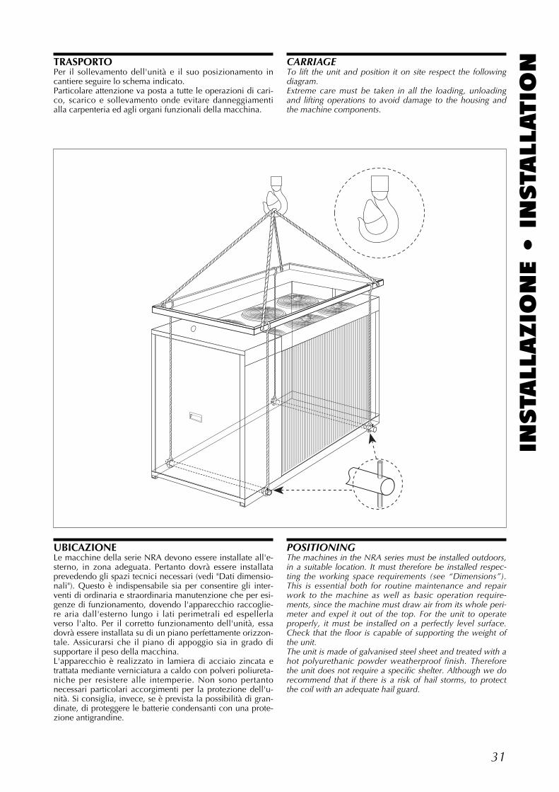
31
INSTA
LLAZIO
NE •
INSTA
LLATIO
NTRASPORTOPer il sollevamento dell'unità e il suo posizionamento incantiere seguire lo schema indicato.Particolare attenzione va posta a tutte le operazioni di cari-co, scarico e sollevamento onde evitare danneggiamentialla carpenteria ed agli organi funzionali della macchina.
CARRIAGETo lift the unit and position it on site respect the followingdiagram.Extreme care must be taken in all the loading, unloadingand lifting operations to avoid damage to the housing andthe machine components.
UBICAZIONELe macchine della serie NRA devono essere installate all'e-sterno, in zona adeguata. Pertanto dovrà essere installataprevedendo gli spazi tecnici necessari (vedi "Dati dimensio-nali"). Questo è indispensabile sia per consentire gli inter-venti di ordinaria e straordinaria manutenzione che per esi-genze di funzionamento, dovendo l'apparecchio raccoglie-re aria dall'esterno lungo i lati perimetrali ed espellerlaverso l'alto. Per il corretto funzionamento dell'unità, essadovrà essere installata su di un piano perfettamente orizzon-tale. Assicurarsi che il piano di appoggio sia in grado disupportare il peso della macchina.L'apparecchio è realizzato in lamiera di acciaio zincata etrattata mediante verniciatura a caldo con polveri poliureta-niche per resistere alle intemperie. Non sono pertantonecessari particolari accorgimenti per la protezione dell'u-nità. Si consiglia, invece, se è prevista la possibilità di gran-dinate, di proteggere le batterie condensanti con una prote-zione antigrandine.
POSITIONINGThe machines in the NRA series must be installed outdoors,in a suitable location. It must therefore be installed respec-ting the working space requirements (see “Dimensions”).This is essential both for routine maintenance and repairwork to the machine as well as basic operation require-ments, since the machine must draw air from its whole peri-meter and expel it out of the top. For the unit to operateproperly, it must be installed on a perfectly level surface.Check that the floor is capable of supporting the weight ofthe unit.The unit is made of galvanised steel sheet and treated with ahot polyurethanic powder weatherproof finish. Thereforethe unit does not require a specific shelter. Although we dorecommend that if there is a risk of hail storms, to protectthe coil with an adequate hail guard.
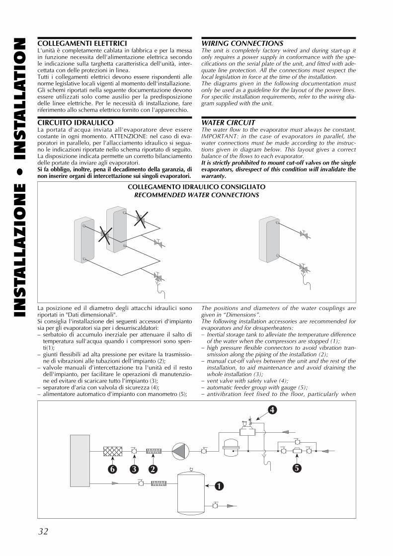
32
INSTA
LLAZIO
NE •
INSTA
LLATIO
N WIRING CONNECTIONSThe unit is completely factory wired and during start-up itonly requires a power supply in conformance with the spe-cifications on the serial plate of the unit, and fitted with ade-quate line protection. All the connections must respect thelocal legislation in force at the time of the installation.The diagrams given in the following documentation mustonly be used as a guideline for the layout of the power lines.For specific installation requirements, refer to the wiring dia-gram supplied with the unit.
WATER CIRCUITThe water flow to the evaporator must always be constant.IMPORTANT: in the case of evaporators in parallel, thewater connections must be made according to the instruc-tions given in diagram below. This layout gives a correctbalance of the flows to each evaporator.It is strictly prohibited to mount cut-off valves on the singleevaporators, disrespect of this condition will invalidate thewarranty.
The positions and diameters of the water couplings aregiven in “Dimensions”.The following installation accessories are recommended forevaporators and for desuperheaters:– Inertial storage tank to alleviate the temperature difference
of the water when the compressors are stopped (1);– high pressure flexible connectors to avoid vibration tran-
smission along the piping of the installation (2);– manual cut-off valves between the unit and the rest of the
installation, to aid maintenance and avoid draining thewhole installation (3);
– vent valve with safety valve (4);– automatic feeder group with gauge (5);– antivibration feet fixed to the floor, particularly when
COLLEGAMENTI ELETTRICIL'unità è completamente cablata in fabbrica e per la messain funzione necessita dell'alimentazione elettrica secondole indicazione sulla targhetta caratteristica dell'unità, inter-cettata con delle protezioni in linea.Tutti i collegamenti elettrici devono essere rispondenti allenorme legislative locali vigenti al momento dell'installazione.Gli schemi riportati nella seguente documentazione devonoessere utilizzati solo come ausilio per la predisposizionedelle linee elettriche. Per le necessità di installazione, fareriferimento allo schema elettrico fornito con l'apparecchio.
CIRCUITO IDRAULICOLa portata d'acqua inviata all'evaporatore deve esserecostante in ogni momento. ATTENZIONE: nel caso di eva-poratori in parallelo, per l’allacciamento idraulico si segua-no le indicazioni riportate nello schema riportato di seguito.La disposizione indicata permette un corretto bilanciamentodelle portate da inviare agli evaporatori.Si fa obbligo, inoltre, pena il decadimento della garanzia, dinon inserire organi di intercettazione sui singoli evaporatori.
La posizione ed il diametro degli attacchi idraulici sonoriportati in "Dati dimensionali".Si consiglia l'installazione dei seguenti accessori d'impiantosia per gli evaporatori sia per i desurriscaldatori:– serbatoio di accumulo inerziale per attenuare il salto di
temperatura sull'acqua quando i compressori sono spen-ti(1);
– giunti flessibili ad alta pressione per evitare la trasmissio-ne di vibrazioni alle tubazioni dell’impianto (2);
– valvole manuali d’intercettazione tra l'unità ed il restodell'impianto, per facilitare le operazioni di manutenzio-ne ed evitare di scaricare tutto l’impianto (3);
– separatore d’aria con valvola di sicurezza (4);– alimentatore automatico d’impianto con manometro (5);
COLLEGAMENTO IDRAULICO CONSIGLIATORECOMMENDED WATER CONNECTIONS
23
1
6
4
5
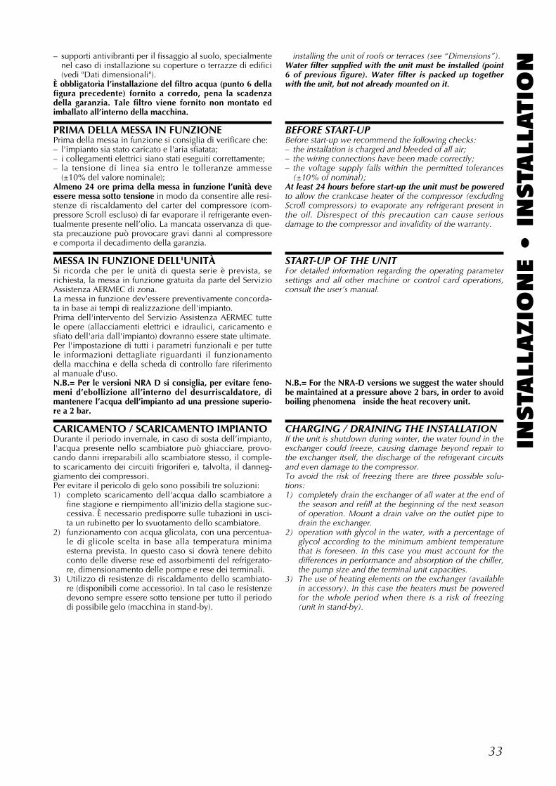
33
INSTA
LLAZIO
NE •
INSTA
LLATIO
N– supporti antivibranti per il fissaggio al suolo, specialmentenel caso di installazione su coperture o terrazze di edifici(vedi "Dati dimensionali").
È obbligatoria l’installazione del filtro acqua (punto 6 dellafigura precedente) fornito a corredo, pena la scadenzadella garanzia. Tale filtro viene fornito non montato edimballato all’interno della macchina.
PRIMA DELLA MESSA IN FUNZIONEPrima della messa in funzione si consiglia di verificare che:– l'impianto sia stato caricato e l'aria sfiatata;– i collegamenti elettrici siano stati eseguiti correttamente;– la tensione di linea sia entro le tolleranze ammesse
(±10% del valore nominale);Almeno 24 ore prima della messa in funzione l’unità deveessere messa sotto tensione in modo da consentire alle resi-stenze di riscaldamento del carter del compressore (com-pressore Scroll escluso) di far evaporare il refrigerante even-tualmente presente nell’olio. La mancata osservanza di que-sta precauzione può provocare gravi danni al compressoree comporta il decadimento della garanzia.
MESSA IN FUNZIONE DELL'UNITÀSi ricorda che per le unità di questa serie è prevista, serichiesta, la messa in funzione gratuita da parte del ServizioAssistenza AERMEC di zona.La messa in funzione dev'essere preventivamente concorda-ta in base ai tempi di realizzazione dell'impianto.Prima dell'intervento del Servizio Assistenza AERMEC tuttele opere (allacciamenti elettrici e idraulici, caricamento esfiato dell'aria dall'impianto) dovranno essere state ultimate.Per l'impostazione di tutti i parametri funzionali e per tuttele informazioni dettagliate riguardanti il funzionamentodella macchina e della scheda di controllo fare riferimentoal manuale d'uso.N.B.= Per le versioni NRA D si consiglia, per evitare feno-meni d’ebollizione all’interno del desurriscaldatore, dimantenere l’acqua dell’impianto ad una pressione superio-re a 2 bar.
CARICAMENTO / SCARICAMENTO IMPIANTODurante il periodo invernale, in caso di sosta dell’impianto,l'acqua presente nello scambiatore può ghiacciare, provo-cando danni irreparabili allo scambiatore stesso, il comple-to scaricamento dei circuiti frigoriferi e, talvolta, il danneg-giamento dei compressori.Per evitare il pericolo di gelo sono possibili tre soluzioni:1) completo scaricamento dell'acqua dallo scambiatore a
fine stagione e riempimento all'inizio della stagione suc-cessiva. È necessario predisporre sulle tubazioni in usci-ta un rubinetto per lo svuotamento dello scambiatore.
2) funzionamento con acqua glicolata, con una percentua-le di glicole scelta in base alla temperatura minimaesterna prevista. In questo caso si dovrà tenere debitoconto delle diverse rese ed assorbimenti del refrigerato-re, dimensionamento delle pompe e rese dei terminali.
3) Utilizzo di resistenze di riscaldamento dello scambiato-re (disponibili come accessorio). In tal caso le resistenzedevono sempre essere sotto tensione per tutto il periododi possibile gelo (macchina in stand-by).
installing the unit of roofs or terraces (see “Dimensions”).Water filter supplied with the unit must be installed (point6 of previous figure). Water filter is packed up togetherwith the unit, but not already mounted on it.
BEFORE START-UPBefore start-up we recommend the following checks:– the installation is charged and bleeded of all air;– the wiring connections have been made correctly;– the voltage supply falls within the permitted tolerances
(±10% of nominal);At least 24 hours before start-up the unit must be poweredto allow the crankcase heater of the compressor (excludingScroll compressors) to evaporate any refrigerant present inthe oil. Disrespect of this precaution can cause seriousdamage to the compressor and invalidity of the warranty.
START-UP OF THE UNITFor detailed information regarding the operating parametersettings and all other machine or control card operations,consult the user’s manual.
N.B.= For the NRA-D versions we suggest the water shouldbe maintained at a pressure above 2 bars, in order to avoidboiling phenomena inside the heat recovery unit.
CHARGING / DRAINING THE INSTALLATIONIf the unit is shutdown during winter, the water found in theexchanger could freeze, causing damage beyond repair tothe exchanger itself, the discharge of the refrigerant circuitsand even damage to the compressor.To avoid the risk of freezing there are three possible solu-tions:1) completely drain the exchanger of all water at the end of
the season and refill at the beginning of the next seasonof operation. Mount a drain valve on the outlet pipe todrain the exchanger.
2) operation with glycol in the water, with a percentage ofglycol according to the minimum ambient temperaturethat is foreseen. In this case you must account for thedifferences in performance and absorption of the chiller,the pump size and the terminal unit capacities.
3) The use of heating elements on the exchanger (availablein accessory). In this case the heaters must be poweredfor the whole period when there is a risk of freezing(unit in stand-by).
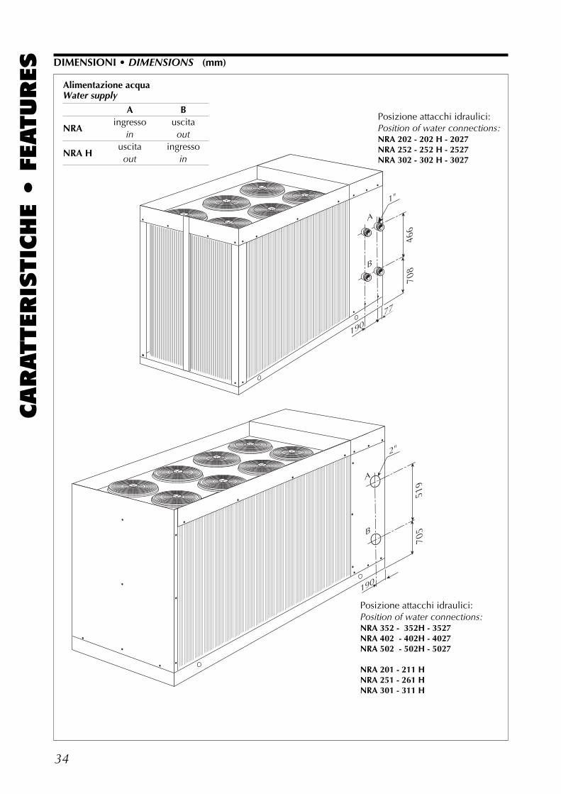
34
CARATTERIS
TIC
HE •
FEATURES DIMENSIONI • DIMENSIONS (mm)
77
190
466
708
519
705
190
1"
2"
A
B
A
B
Posizione attacchi idraulici:Position of water connections:NRA 202 - 202 H - 2027NRA 252 - 252 H - 2527NRA 302 - 302 H - 3027
Alimentazione acquaWater supply
A B
NRAingresso uscita
in out
NRA Huscita ingressoout in
Posizione attacchi idraulici:Position of water connections:NRA 352 - 352H - 3527NRA 402 - 402H - 4027NRA 502 - 502H - 5027
NRA 201 - 211 HNRA 251 - 261 HNRA 301 - 311 H
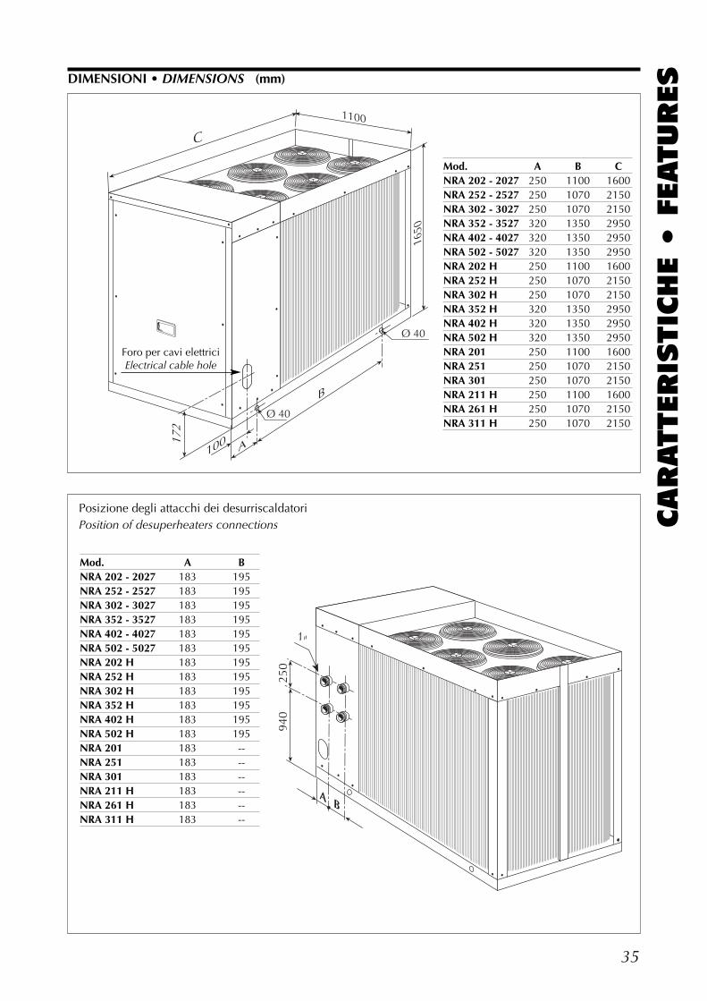
940
250
1"
AB
35
CARATTERIS
TIC
HE •
FEATURES
1100
1650
C
100172
A
B
Ø 40
Ø 40
Mod. A B CNRA 202 - 2027 250 1100 1600NRA 252 - 2527 250 1070 2150NRA 302 - 3027 250 1070 2150NRA 352 - 3527 320 1350 2950NRA 402 - 4027 320 1350 2950NRA 502 - 5027 320 1350 2950NRA 202 H 250 1100 1600NRA 252 H 250 1070 2150NRA 302 H 250 1070 2150NRA 352 H 320 1350 2950NRA 402 H 320 1350 2950NRA 502 H 320 1350 2950NRA 201 250 1100 1600NRA 251 250 1070 2150NRA 301 250 1070 2150NRA 211 H 250 1100 1600NRA 261 H 250 1070 2150NRA 311 H 250 1070 2150
Posizione degli attacchi dei desurriscaldatori Position of desuperheaters connections
Foro per cavi elettriciElectrical cable hole
DIMENSIONI • DIMENSIONS (mm)
Mod. A BNRA 202 - 2027 183 195NRA 252 - 2527 183 195NRA 302 - 3027 183 195NRA 352 - 3527 183 195NRA 402 - 4027 183 195NRA 502 - 5027 183 195NRA 202 H 183 195NRA 252 H 183 195NRA 302 H 183 195NRA 352 H 183 195NRA 402 H 183 195NRA 502 H 183 195NRA 201 183 --NRA 251 183 --NRA 301 183 --NRA 211 H 183 --NRA 261 H 183 --NRA 311 H 183 --
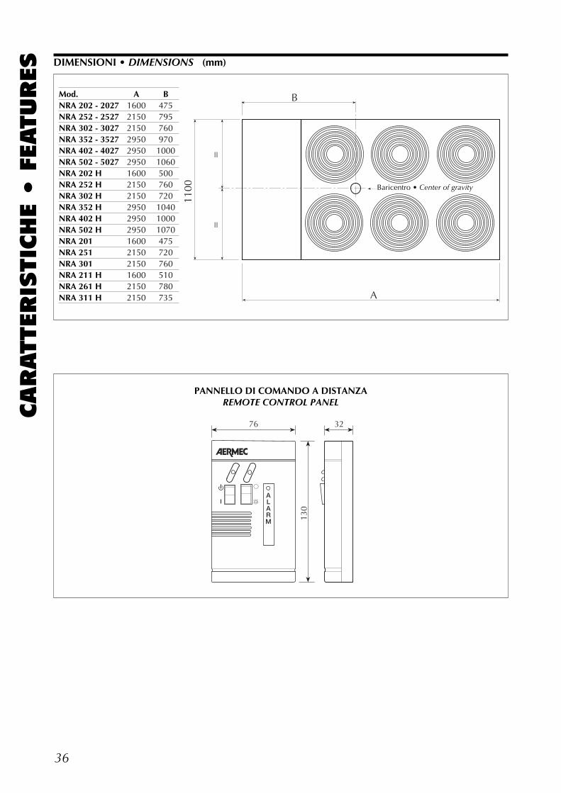
36
CARATTERIS
TIC
HE •
FEATURES DIMENSIONI • DIMENSIONS (mm)
32
130
76
PANNELLO DI COMANDO A DISTANZAREMOTE CONTROL PANEL
1100
B
A
==
Mod. A BNRA 202 - 2027 1600 475NRA 252 - 2527 2150 795NRA 302 - 3027 2150 760NRA 352 - 3527 2950 970NRA 402 - 4027 2950 1000NRA 502 - 5027 2950 1060NRA 202 H 1600 500NRA 252 H 2150 760NRA 302 H 2150 720NRA 352 H 2950 1040NRA 402 H 2950 1000NRA 502 H 2950 1070NRA 201 1600 475NRA 251 2150 720NRA 301 2150 760NRA 211 H 1600 510NRA 261 H 2150 780NRA 311 H 2150 735
Baricentro • Center of gravity
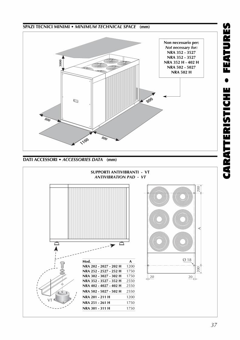
37
CARATTERIS
TIC
HE •
FEATURESSPAZI TECNICI MINIMI • MINIMUM TECHNICAL SPACE (mm)
DATI ACCESSORI • ACCESSORIES DATA (mm)
3000
800
8001100
800
Non necessario per:Not necessary for:NRA 352 - 3527NRA 352 - 3527
NRA 352 H - 402 HNRA 502 - 5027
NRA 502 H
20
Ø 18
A20
020
0
VT
20
SUPPORTI ANTIVIBRANTI - VTANTIVIBRATION PAD - VT
Mod. ANRA 202 - 2027 - 202 H 1200NRA 252 - 2527 - 252 H 1750NRA 302 - 3027 - 302 H 1750NRA 352 - 3527 - 352 H 2550NRA 402 - 4027 - 402 H 2550
NRA 502 - 5027 - 502 H 2550
NRA 201 - 211 H 1200
NRA 251 - 261 H 1750
NRA 301 - 311 H 1750
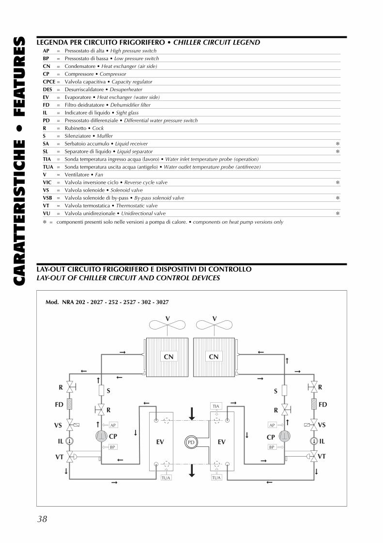
38
CARATTERIS
TIC
HE •
FEATURES LEGENDA PER CIRCUITO FRIGORIFERO • CHILLER CIRCUIT LEGEND
AP = Pressostato di alta • High pressure switch
BP = Pressostato di bassa • Low pressure switch
CN = Condensatore • Heat exchanger (air side)
CP = Compressore • Compressor
CPCE = Valvola capacitiva • Capacity regulator
DES = Desurriscaldatore • Desuperheater
EV = Evaporatore • Heat exchanger (water side)
FD = Filtro deidratatore • Dehumidifier filter
IL = Indicatore di liquido • Sight glass
PD = Pressostato differenziale • Differential water pressure switch
R = Rubinetto • Cock
S = Silenziatore • Muffler
SA = Serbatoio accumulo • Liquid receiver ❄
SL = Separatore di liquido • Liquid separator ❄
TIA = Sonda temperatura ingresso acqua (lavoro) • Water inlet temperature probe (operation)
TUA = Sonda temperatura uscita acqua (antigelo) • Water outlet temperature probe (antifreeze)
V = Ventilatore • Fan
VIC = Valvola inversione ciclo • Reverse cycle valve ❄
VS = Valvola solenoide • Solenoid valve
VSB = Valvola solenoide di by-pass • By-pass solenoid valve ❄
VT = Valvola termostatica • Thermostatic valve
VU = Valvola unidirezionale • Unidirectional valve ❄
❄ = componenti presenti solo nelle versioni a pompa di calore. • components on heat pump versions only
V
FD
IL
VS
VT
S
CP
R R
S
CP
R
FD
IL
VS
VT
PD
CN
R
AP
BP
TUA TUA
TIA
BP
AP
EVEV
CN
V
Mod. NRA 202 - 2027 - 252 - 2527 - 302 - 3027
LAY-OUT CIRCUITO FRIGORIFERO E DISPOSITIVI DI CONTROLLOLAY-OUT OF CHILLER CIRCUIT AND CONTROL DEVICES
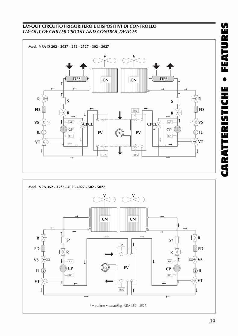
39
CARATTERIS
TIC
HE •
FEATURES
R
FD
IL
VS
VT
S*
CP
R R
S*
CP
R
FD
IL
VS
VTBP
AP
TIA
AP
BP
PD EV
V
CN CN
V
TUA
Mod. NRA 352 - 3527 - 402 - 4027 - 502 - 5027
* = escluso • excluding NRA 352 - 3527
LAY-OUT CIRCUITO FRIGORIFERO E DISPOSITIVI DI CONTROLLOLAY-OUT OF CHILLER CIRCUIT AND CONTROL DEVICES
V
FD
IL
VS
VT
S
CP
R R
S
CP
R
FD
IL
VS
VT
PD
CN
R
AP
BP
TUA TUA
TIA
BP
AP
EVEV
CN
V
DES DES
CPCE CPCE
Mod. NRA-D 202 - 2027 - 252 - 2527 - 302 - 3027
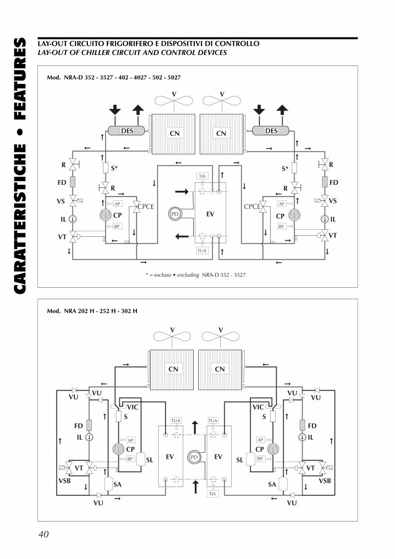
40
CARATTERIS
TIC
HE •
FEATURES
R
FD
IL
VS
VT
S*
CP
R R
S*
CP
R
FD
IL
VS
VTBP
AP
TIA
AP
BP
PD EV
V
CN CN
V
TUA
DES DES
CPCE CPCE
V
FD
IL
VT
S
CPPD
CN
AP
BP
TUA TUA
TIA
EVEV
CN
V
SL
SAVSB
VIC
FD
IL
VT
S
CPAP
BPSL
SA VSB
VIC
VU
VUVU
VU
VUVU
Mod. NRA-D 352 - 3527 - 402 - 4027 - 502 - 5027
Mod. NRA 202 H - 252 H - 302 H
* = escluso • excluding NRA-D 352 - 3527
LAY-OUT CIRCUITO FRIGORIFERO E DISPOSITIVI DI CONTROLLOLAY-OUT OF CHILLER CIRCUIT AND CONTROL DEVICES
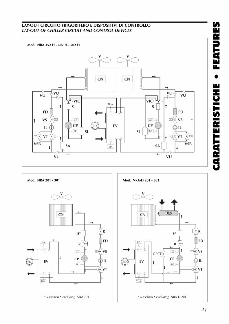
41
CARATTERIS
TIC
HE •
FEATURES
R
S*
CP
R
FD
IL
VS
VT
PD
TUA
TIA
BP
AP
EV
CN
V
* = escluso • excluding NRA 201
V
FD
IL
VS
VT
S
CP
CN
AP
BP
CN
V
SL
SAVSB
VIC
FD
IL
VS
VT
S
CPAP
BPSL
SA VSB
VIC
PD EV
VUVU
VU VU
VU VU
TIA
TUA
Mod. NRA 352 H - 402 H - 502 H
LAY-OUT CIRCUITO FRIGORIFERO E DISPOSITIVI DI CONTROLLOLAY-OUT OF CHILLER CIRCUIT AND CONTROL DEVICES
Mod. NRA 201 - 301
R
S*
CP
R
FD
IL
VS
VT
PD
TUA
TIA
BP
AP
EV
CN
V
DES
CPCE
* = escluso • excluding NRA-D 201
Mod. NRA-D 201 - 301
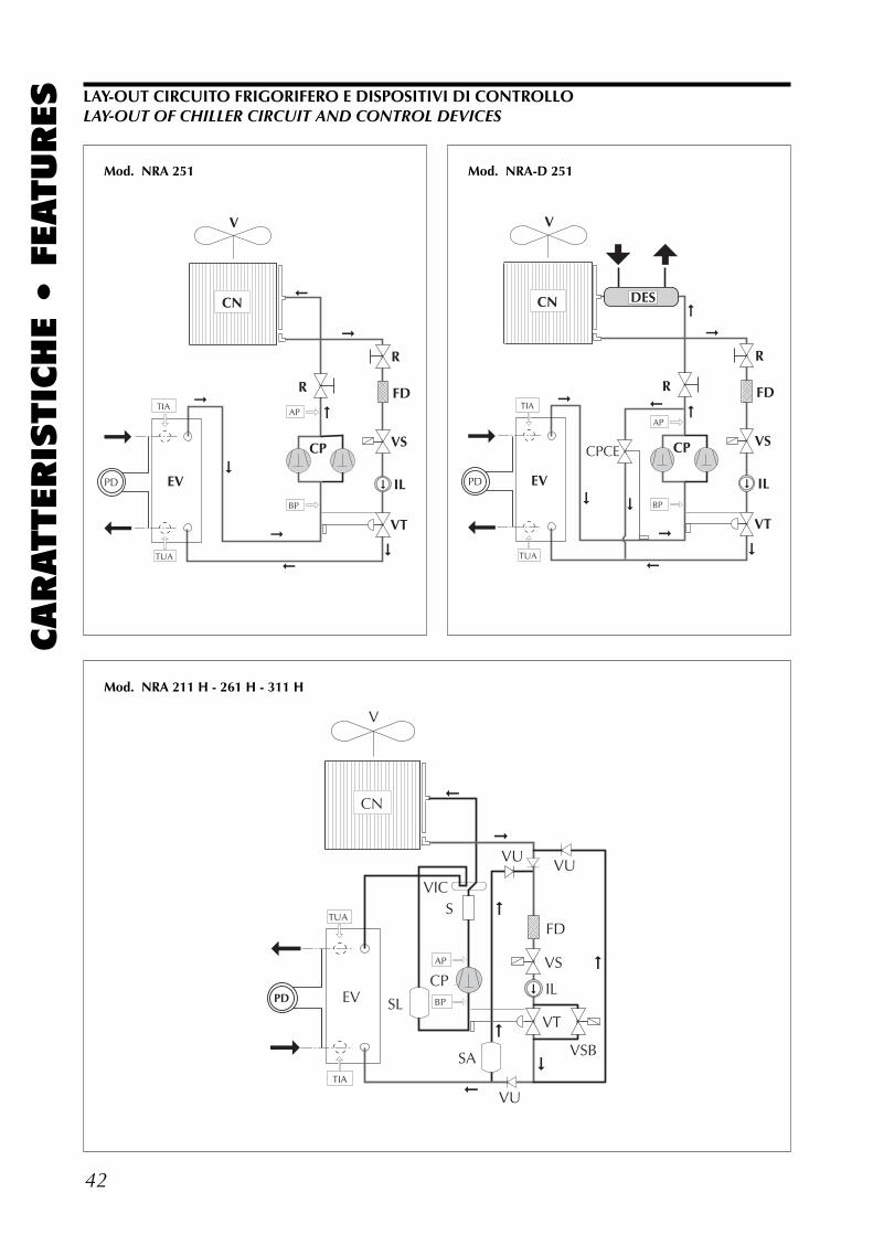
42
CARATTERIS
TIC
HE •
FEATURES
R
CP
R
FD
IL
VS
VT
PD
TUA
TIA
BP
AP
EV
CN
V
PD
TUA
TIA
EV
CN
V
FD
IL
VS
VT
S
CPAP
BPSL
SA VSB
VIC
VU
VUVU
Mod. NRA 251
R
CP
R
FD
IL
VS
VT
PD
TUA
TIA
BP
AP
EV
CN
V
DES
CPCE
Mod. NRA-D 251
Mod. NRA 211 H - 261 H - 311 H
LAY-OUT CIRCUITO FRIGORIFERO E DISPOSITIVI DI CONTROLLOLAY-OUT OF CHILLER CIRCUIT AND CONTROL DEVICES
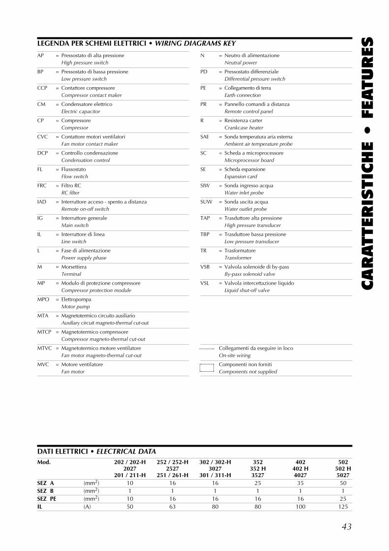
43
CARATTERIS
TIC
HE •
FEATURESLEGENDA PER SCHEMI ELETTRICI • WIRING DIAGRAMS KEY
AP = Pressostato di alta pressioneHigh pressure switch
BP = Pressostato di bassa pressioneLow pressure switch
CCP = Contattore compressoreCompressor contact maker
CM = Condensatore elettricoElectric capacitor
CP = CompressoreCompressor
CVC = Contattore motori ventilatoriFan motor contact maker
DCP = Controllo condensazioneCondensation control
FL = FlussostatoFlow switch
FRC = Filtro RCRC filter
IAD = Interruttore acceso - spento a distanzaRemote on-off switch
IG = Interruttore generaleMain switch
IL = Interruttore di lineaLine switch
L = Fase di alimentazionePower supply phase
M = MorsettieraTerminal
MP = Modulo di protezione compressoreCompressor protection module
MPO = ElettropompaMotor pump
MTA = Magnetotermico circuito ausiliarioAuxiliary circuit magneto-thermal cut-out
MTCP = Magnetotermico compressoreCompressor magneto-thermal cut-out
MTVC = Magnetotermico motore ventilatoreFan motor magneto-thermal cut-out
MVC = Motore ventilatoreFan motor
N = Neutro di alimentazioneNeutral power
PD = Pressostato differenzialeDifferential pressure switch
PE = Collegamento di terraEarth connection
PR = Pannello comandi a distanzaRemote control panel
R = Resistenza carterCrankcase heater
SAE = Sonda temperatura aria esternaAmbient air temperature probe
SC = Scheda a microprocessoreMicroprocessor board
SE = Scheda espansioneExpansion card
SIW = Sonda ingresso acquaWater inlet probe
SUW = Sonda uscita acquaWater outlet probe
TAP = Trasduttore alta pressioneHigh pressure transducer
TBP = Trasduttore bassa pressioneLow pressure transducer
TR = TrasformatoreTransformer
VSB = Valvola solenoide di by-passBy-pass solenoid valve
VSL = Valvola intercettazione liquidoLiquid shut-off valve
Collegamenti da eseguire in locoOn-site wiring
Componenti non fornitiComponents not supplied
DATI ELETTRICI • ELECTRICAL DATAMod. 202 / 202-H 252 / 252-H 302 / 302-H 352 402 502
2027 2527 3027 352 H 402 H 502 H201 / 211-H 251 / 261-H 301 / 311-H 3527 4027 5027
SEZ A (mm2) 10 16 16 25 35 50SEZ B (mm2) 1 1 1 1 1 1SEZ PE (mm2) 10 16 16 16 16 25IL (A) 50 63 80 80 100 125
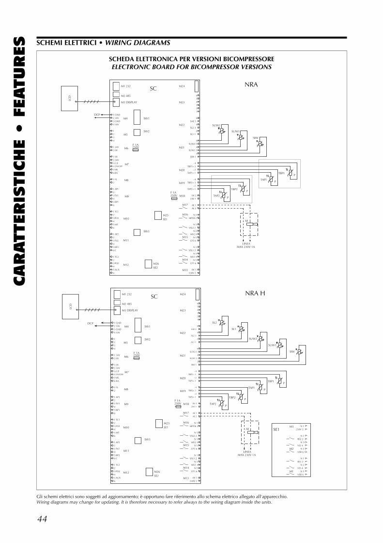
44
CARATTERIS
TIC
HE •
FEATURES SCHEMI ELETTRICI • WIRING DIAGRAMS
Gli schemi elettrici sono soggetti ad aggiornamento; è opportuno fare riferimento allo schema elettrico allegato all'apparecchio.Wiring diagrams may change for updating. It is therefore necessary to refer always to the wiring diagram inside the units.
���
��� ������������� ���
��
�� ���
���� ������ �������
��������
����
���������� ������
���������� �����
�������� �������
�������� ������
����
�� ��
����������
��
��
��
��
��
���
��
�
��
� �
�
� �
��
���!
���!�
�
��
�
��
�
���
���
���
���
���
��
���
�� ��
���!��
����
�����
��� ��
�� ���
�� ��
"� ����#��
"�����#��
"� ���#��
"����#��
�� ���
�!���!�
������!�
����������
��� ���
����
�����������
���� ���
�����
������
���!����������
�
�
������
������
�!
����
�� �
����
��
��
�
�
���
���
SCHEDA ELETTRONICA PER VERSIONI BICOMPRESSOREELECTRONIC BOARD FOR BICOMPRESSOR VERSIONS
LCD
1 GND2 10V3 GND4 10V
1234
1 24V2 0V
1 0V2 24V3 C/F4 ON/OFF
5 VR6 RA
1 FL2
1 AP123 TV145 BP16
1 TC123 PO145 MT6
1 AP223 TV245 BP26 C
1 TC223 PO245 AUX6
M1 232
M2 485
M3 DISPLAY
M5
M6
M8
M9
M10
M11
M12
M4
M7
SW1
SW2
SW3
SC
M26SE2
M25SE1
M24
M23
M22
M21
M20
M19
M18
M17
M16
M15
M14
M13
6
5
4
3
2
1
6
SAE 5
4
SL2 3
2
SL1 1
6
SUW2 5
4
SUW1 3
2
SIW 1
- 4
TBP1+ 3
- 2
TAP1+ 1
- 4
TBP2+ 3
- 2
TAP2+ 1
0V 2
24V 1
AE 1
AE 2
N 1MPOE 2
N 1VSL2 2
N 3MV2 4
N 5CP2 6
N 1VSL1 2
N 3MV1 4
N 5CP1 6
0V 1230V 2
P
P
LINEAMAX 230V 1A
P
SE1
P
M3
M2
M1
N 1230V 2
N 1RS2 2
N 3VI2 4
N 5VSB 6
N 1RS1 2
N 3VI1 4
N 5VSB 6
F 1A250V
F 1A250V
SL2
TAP2
SL1
TBP2
AE
SUW2
TAP1
SUW1
TBP1
SIW
DCP
NRA
NRA H
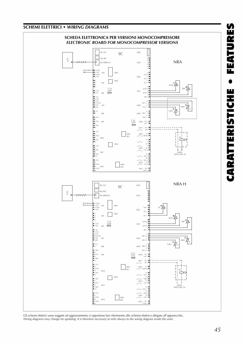
45
CARATTERIS
TIC
HE •
FEATURESSCHEMI ELETTRICI • WIRING DIAGRAMS
Gli schemi elettrici sono soggetti ad aggiornamento; è opportuno fare riferimento allo schema elettrico allegato all'apparecchio.Wiring diagrams may change for updating. It is therefore necessary to refer always to the wiring diagram inside the units.
���
��� ������������� ���
��
�� ���
���� ������ �������
��������
����
���������� ������
���������� �����
�������� �������
�������� ������
����
�� ��
����������
��
��
��
��
��
���
��
�
��
� �
�
� �
��
���!
���!�
�
��
�
��
�
���
���
���
���
���
��
���
�� ��
���!��
����
�����
��� ��
�� ���
�� ��
"� ����#��
"�����#��
"� ���#��
"����#��
�� ���
�!���!�
������!�
������
�������
�����������
���� ���
�����
������
�
���!����������
�
������
������
��
����
�!
��
����
SCHEDA ELETTRONICA PER VERSIONI MONOCOMPRESSOREELECTRONIC BOARD FOR MONOCOMPRESSOR VERSIONS
LCD
DCP 1 GND2 10V3 GND4 10V
1234
1 24V2 0V
1 0V2 24V3 C/F4 ON/OFF
5 VR6 RA
1 FL2
1 AP123 TV145 BP16
1 TC123 PO145 MT6
1 AP223 TV245 BP26 C
1 TC223 PO245 AUX6
M1 232
M2 485
M3 DISPLAY
M5
M6
M8
M9
M10
M11
M12
M4
M7
SW1
SW2
SW3
SC
M26SE2
M25SE1
M24
M23
M22
M21
M20
M19
M18
M17
M16
M15
M14
M13
654321
6SAE 5
4SL2 3
2SL1 1
6SUW2 5
4SUW1 3
2SIW 1
- 4TBP1+ 3
- 2TAP1+ 1
- 4TBP2+ 3
- 2TAP2+ 1
0V 224V 1
AE 1AE 2
N 1MPOE 2
N 1VIC 2
N 3VSB 4
N 5CP2 6
N 1VSL1 2
N 3MV1 4
N 5CP1 6
0V 1230V 2
P
LINEAMAX 230V 1A
P
F 1A250V
F 1A250V
SL
SUW
TAP1
AE
SIW
TBP1
NRA
NRA H
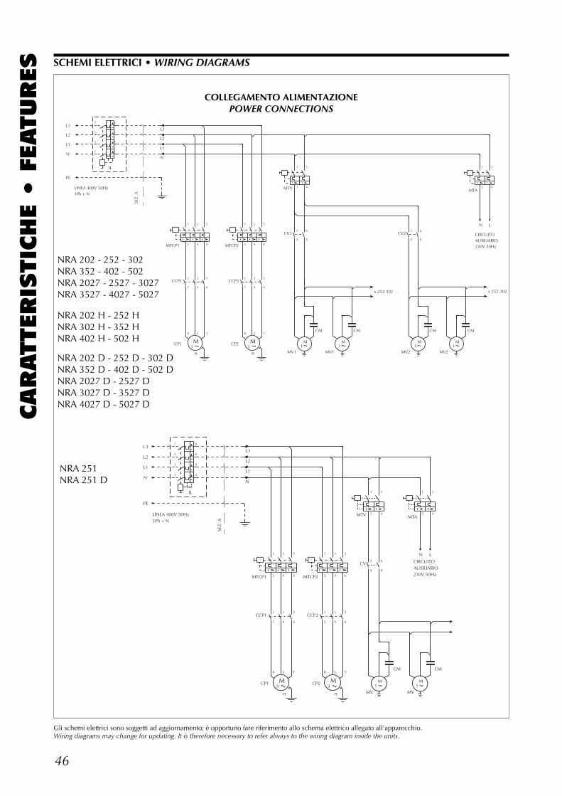
46
CARATTERIS
TIC
HE •
FEATURES SCHEMI ELETTRICI • WIRING DIAGRAMS
Gli schemi elettrici sono soggetti ad aggiornamento; è opportuno fare riferimento allo schema elettrico allegato all'apparecchio.Wiring diagrams may change for updating. It is therefore necessary to refer always to the wiring diagram inside the units.
NRA 202-30267936.00
1
7
L3
L2
L1
N
M3
M3
L3
L2
L1
N’
PE
LINEA 400V 50Hz3Ph + N
SEZ
. A
M1
M1
x 252-302
M1
M1
CIRCUITOAUSILIARIO230V 50Hz
N L
IL
MTCP1
CCP1
CP1
MTCP2
CCP2
CP2
MTV
CV1
MV1
CM
MV1
CM
CV2
MV2
CM
MV2
CM
MTA
7
5
3
1
8
6
4
2
1
2
3
4
5
6
1
2
R S
PE
T
3
4
5
6
1
2
3
4
5
6
1
2
R S
PE
T
3
4
5
6
1
2
3
4
2
4
6
8
2
4
6
8
1
2
3
4
x 252-302
NRA 202 - 252 - 302NRA 352 - 402 - 502NRA 2027 - 2527 - 3027NRA 3527 - 4027 - 5027
COLLEGAMENTO ALIMENTAZIONEPOWER CONNECTIONS
NRA 202 D - 252 D - 302 DNRA 352 D - 402 D - 502 DNRA 2027 D - 2527 DNRA 3027 D - 3527 DNRA 4027 D - 5027 D
NRA 202 H - 252 HNRA 302 H - 352 HNRA 402 H - 502 H
L3
L2
L1
N
M3
M3
L3
L2
L1
N’
PE
LINEA 400V 50Hz3Ph + N
SEZ
. A
M1
CIRCUITOAUSILIARIO230V 50Hz
M1
N L
IL
MTCP1
CCP1
CP1
MTCP2
CCP2
CP2
MTV
CV
MV
CM
MV
MTA
CM
7
5
3
1
8
6
4
2
1
2
3
4
5
6
1
2
R S
PE
T
3
4
5
6
1
2
3
4
5
6
1
2
R S
PE
T
3
4
5
6
1
2
3
4
2
4
6
8
1
2
3
4
NRA 251NRA 251 D
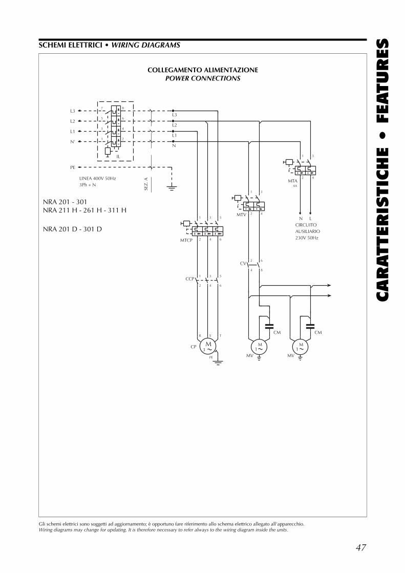
47
CARATTERIS
TIC
HE •
FEATURESSCHEMI ELETTRICI • WIRING DIAGRAMS
Gli schemi elettrici sono soggetti ad aggiornamento; è opportuno fare riferimento allo schema elettrico allegato all'apparecchio.Wiring diagrams may change for updating. It is therefore necessary to refer always to the wiring diagram inside the units.
L3
L2
L1
N
M3
4A
L3
L2
L1
N’
PE
LINEA 400V 50Hz3Ph + N
SEZ
. A
M1
CIRCUITOAUSILIARIO230V 50Hz
M1
N L
IL
MTCP
CCP
CP
MTV
CV
MV
CM
MV
MTA
CM
7
5
3
1
8
6
4
2
1
2
3
4
5
6
1
2
R S
PE
T
3
4
5
6
1
2
3
4
2
4
6
8
1
2
3
4
COLLEGAMENTO ALIMENTAZIONEPOWER CONNECTIONS
NRA 201 - 301NRA 211 H - 261 H - 311 H
NRA 201 D - 301 D
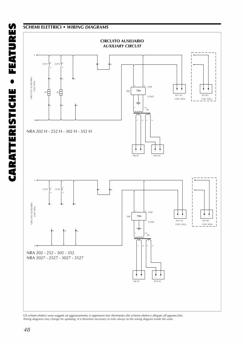
48
CARATTERIS
TIC
HE •
FEATURES
CIR
CU
ITO
AU
SILI
AR
IO23
0V 5
0Hz
L
N
2 1
LINE
LOAD
2 1
M13 SC
230V 50Hz
1 2
230V 50Hz
1 2
1
2
3
4
5
6
7 8
M6 SC M18 SC
M3 SE1
CCP1
R1
CCP2
R2 FRC
TR
21
22
21
22
L1 L2
0
0 24
230
0 24
SCHEMI ELETTRICI • WIRING DIAGRAMS
Gli schemi elettrici sono soggetti ad aggiornamento; è opportuno fare riferimento allo schema elettrico allegato all'apparecchio.Wiring diagrams may change for updating. It is therefore necessary to refer always to the wiring diagram inside the units.
CIRCUITO AUSILIARIOAUXILIARY CIRCUIT
NRA 202 H - 252 H - 302 H - 352 H
CIR
CU
ITO
AU
SILI
AR
IO23
0V 5
0Hz
L
N
2 1
LINE
LOAD
2 1
M13 SC
230V 50Hz
1 2
230V 50Hz
1 2
1
2
3
4
5
6
7 8
M6 SC M18 SC
M3 SE1
CCP1 CCP2
FRC
TR
21
22
21
22
L1 L2
0
0 24
230
0 24
NRA 202 - 252 - 302 - 352NRA 2027 - 2527 - 3027 - 3527
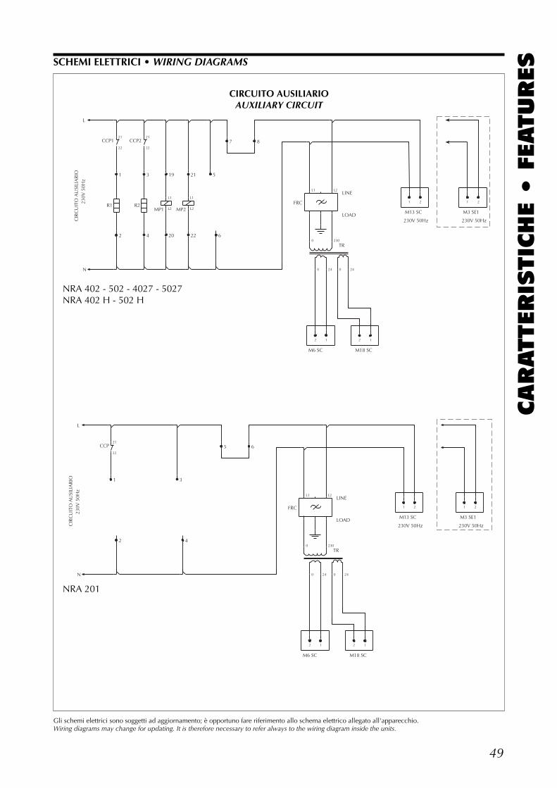
49
CARATTERIS
TIC
HE •
FEATURESSCHEMI ELETTRICI • WIRING DIAGRAMS
Gli schemi elettrici sono soggetti ad aggiornamento; è opportuno fare riferimento allo schema elettrico allegato all'apparecchio.Wiring diagrams may change for updating. It is therefore necessary to refer always to the wiring diagram inside the units.
CIR
CU
ITO
AU
SILI
AR
IO23
0V 5
0Hz
L
N
2 1
LINE
LOAD
2 1
M13 SC
230V 50Hz
1 2
M3 SE1
230V 50Hz
1 2
1
2
3
4
19
20
21
22
5
6
7 8
M6 SC M18 SC
CCP1
R1
CCP2
R2MP1 MP2
FRC
TR
21
22
21
22
L1
L2
L1
L2
L1 L2
0
0 24
230
0 24
NRA 402 - 502 - 4027 - 5027NRA 402 H - 502 H
CIRCUITO AUSILIARIOAUXILIARY CIRCUIT
CIR
CU
ITO
AU
SILI
AR
IO23
0V 5
0Hz
L
N
2 1
LINE
LOAD
2 1
M13 SC
230V 50Hz
1 2
230V 50Hz
1 2
1
2
3
4
5 6
M6 SC M18 SC
M3 SE1
CCP
FRC
TR
21
22
L1 L2
0
0 24
230
0 24
NRA 201
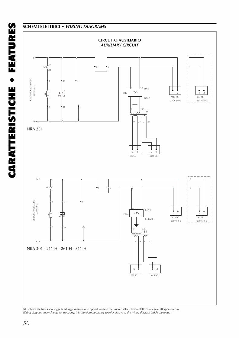
50
CARATTERIS
TIC
HE •
FEATURES SCHEMI ELETTRICI • WIRING DIAGRAMS
Gli schemi elettrici sono soggetti ad aggiornamento; è opportuno fare riferimento allo schema elettrico allegato all'apparecchio.Wiring diagrams may change for updating. It is therefore necessary to refer always to the wiring diagram inside the units.
CIR
CU
ITO
AU
SILI
AR
IO
230V
50H
z
L
N
2 1
LINE
LOAD
2 1
M13 SC
230V 50Hz
1 2
230V 50Hz
1 2
1
2
15
16
3
4
5 6
M6 SC M18 SC
M3 SE1
CCP
RMP
FRC
TR
21
22
L1
L2
L1 L2
0
0 24
230
0 24
NRA 251
CIRCUITO AUSILIARIOAUXILIARY CIRCUIT
CIR
CU
ITO
AU
SILI
AR
IO23
0V 5
0Hz
�
N
3
LINE
LOADM13 SC
230V 50Hz
1 2
230V 50Hz
1 2
1
2
15
16
3
4
5 6
M6 SC M18 SC
M3 SE1
CCP
RMP
FRC
TR
21
22
L1
L2
L1 L2
0
0 24
230
0 24
NRA 301 - 211 H - 261 H - 311 H
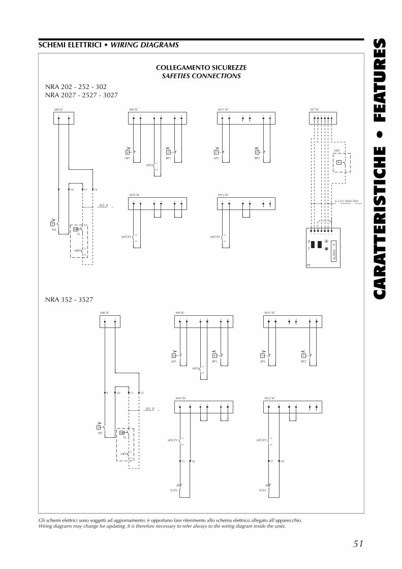
51
CARATTERIS
TIC
HE •
FEATURESSCHEMI ELETTRICI • WIRING DIAGRAMS
Gli schemi elettrici sono soggetti ad aggiornamento; è opportuno fare riferimento allo schema elettrico allegato all'apparecchio.Wiring diagrams may change for updating. It is therefore necessary to refer always to the wiring diagram inside the units.
M8 SC
1
P
2
10 11
SEZ. B
1
P
1
2
2
3
3
4
4
5
P
5
6
6
M11 SC
M12 SC
1
P
1
2
2
3
3
4
4
5
P
5
6
6
PR
0
1
M7 SC
6 x 0,5 MAX 50m
7
6
6
5
5
4
4
3
3
2
2
1
1
IAD
ALA
RM
PDFL
MPO
AP1
MTCP1
MTV
BP1 AP2
MTCP2
BP2
13
14
12
M9 SC
M10 SC
13
14
13
14
13
14
67936.0047
NRA 202 - 252 - 302NRA 2027 - 2527 - 3027
COLLEGAMENTO SICUREZZESAFETIES CONNECTIONS
M8 SC
1
9
P
2
10 11
SEZ. B
1
P
1
15
2
2
16
3
3
4
4
5
P
5
6
6
M11 SC
M12 SC
1
P
1
17
2
2
18
3
3
4
4
5
P
5
6
6
PDFL
MPO
AP1
MTCP1
TCP1
MTV
BP1 AP2
MTCP2
TCP2
BP2
13
14
12
M9 SC
M10 SC
13
14
13
14
13
14
NRA 352 - 3527
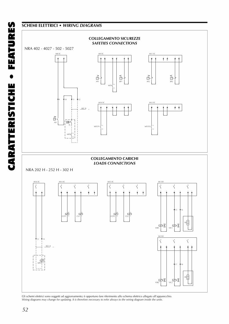
52
CARATTERIS
TIC
HE •
FEATURES SCHEMI ELETTRICI • WIRING DIAGRAMS
Gli schemi elettrici sono soggetti ad aggiornamento; è opportuno fare riferimento allo schema elettrico allegato all'apparecchio.Wiring diagrams may change for updating. It is therefore necessary to refer always to the wiring diagram inside the units.
M8 SC
1
9
P
2
10 11
SEZ. B
1
P
1
2
2
3
3
4
4
5
P
5
6
6
M11 SC
M12 SC
1
P
1
2
2
3
3
4
4
5
P
5
6
6
PDFL
MPO
AP1
MTCP1
MTV
BP1 AP2
MTCP2
BP2
13
14
12
M9 SC
M10 SC
13
14
13
14
13
14
COLLEGAMENTO SICUREZZESAFETIES CONNECTIONS
M16 SC
2
13
SEZ. B
1
14
6 5 4 3 2 1
M15 SC
6 5 4 3 2 1
M1 SE1
M2 SE1
6
6
5
5
4
15
4
17
3
16
3
18
2
2
1
1
MPO
CCP1 CV1 CCP2 CV2
VSB1
VSB2
VIC1
VIC2
RS
RS
A2
A1
M14 SC
A2
A1
0
1
A2
A1
0
1
NRA 202 H - 252 H - 302 H
NRA 402 - 4027 - 502 - 5027
COLLEGAMENTO CARICHILOADS CONNECTIONS
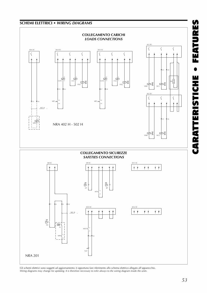
53
CARATTERIS
TIC
HE •
FEATURES
M16 SC
2
13
SEZ. B
1
14
6
15
5
16
4 3 2 1
M15 SC
6
17
5
18
4 3 2 1
M1 SE1
M2 SE1
6
6
5
5
4
23
4
25
3
24
3
26
2
2
1
1
MPO
MP1
CCP1 CV1
VSL1
MP2
CCP2 CV2
VSL2VSB1
VSB2
VIC1
VIC2
RS
A2
A1
M14 SC
M1
M2
A2
A1
0
1
M1
M2
A2
A1
0
1
SCHEMI ELETTRICI • WIRING DIAGRAMS
Gli schemi elettrici sono soggetti ad aggiornamento; è opportuno fare riferimento allo schema elettrico allegato all'apparecchio.Wiring diagrams may change for updating. It is therefore necessary to refer always to the wiring diagram inside the units.
M8 SC
1
7
P
2
8 9
SEZ. B
1
P
1
2
2
14
3
3
4
4
5
P
5
6
6
M11 SC
M12 SC
1
1
2
2
3
3
4
4
5
5
6
6
PDFL
MPO
AP
MTCP
TCP
MTV
BP
13
14
10
M9 SC
M10 SC
13
14
13
13
14
NRA 201
NRA 402 H - 502 H
COLLEGAMENTO CARICHILOADS CONNECTIONS
COLLEGAMENTO SICUREZZESAFETIES CONNECTIONS
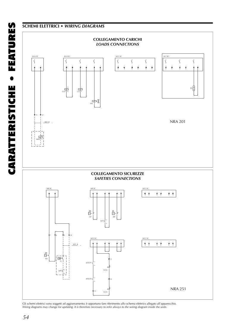
54
CARATTERIS
TIC
HE •
FEATURES
M16 SC
2
11
SEZ. B
1
12
6 5 4 3 2 1
M15 SC
6 5 4 3 2 1
M1 SE1
6 5 4 3 2 1
MPO
CCP CV
VSL
RS
A2
A1
M14 SC
A1
A2
1
0
M8 SC
1
7
P
2
8 9
SEZ. B
1
P
1
13
2
2
3
3
4
4
15
14
5
P
5
6
6
M11 SC
M12 SC
1
1
2
2
3
3
4
4
5
5
6
6
PDFL
MPO
AP
MTCP1
MTCP2
MTV
TCP2
TCP1
BP
13
14
10
M9 SC
M10 SC
13
14
13
14
13
14
NRA 201
SCHEMI ELETTRICI • WIRING DIAGRAMS
Gli schemi elettrici sono soggetti ad aggiornamento; è opportuno fare riferimento allo schema elettrico allegato all'apparecchio.Wiring diagrams may change for updating. It is therefore necessary to refer always to the wiring diagram inside the units.
NRA 251
COLLEGAMENTO SICUREZZESAFETIES CONNECTIONS
COLLEGAMENTO CARICHILOADS CONNECTIONS
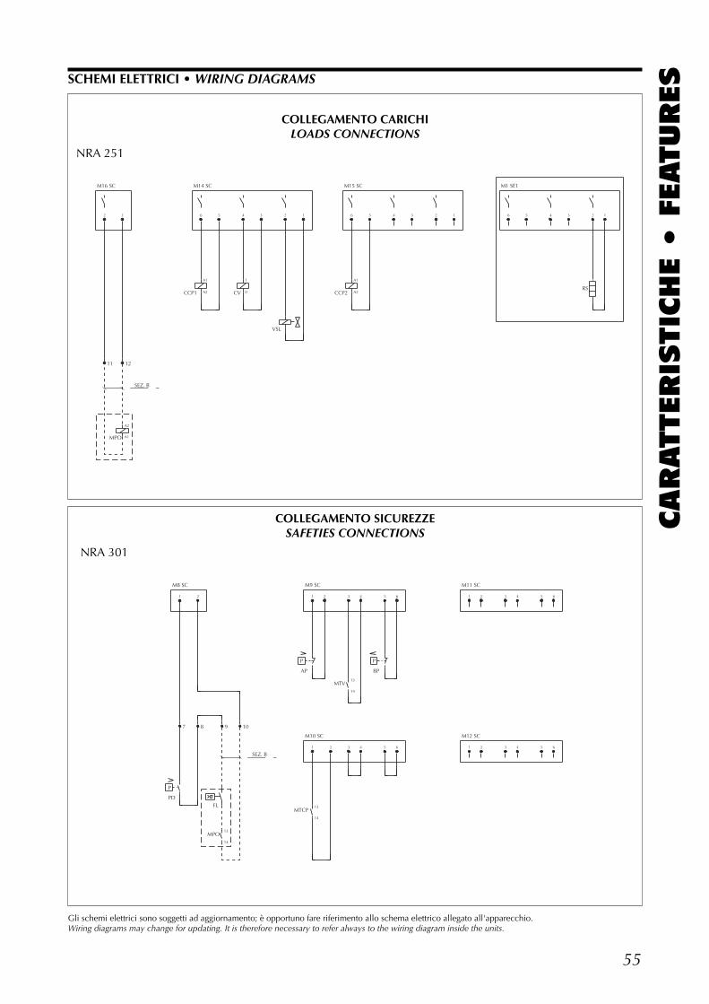
55
CARATTERIS
TIC
HE •
FEATURESSCHEMI ELETTRICI • WIRING DIAGRAMS
Gli schemi elettrici sono soggetti ad aggiornamento; è opportuno fare riferimento allo schema elettrico allegato all'apparecchio.Wiring diagrams may change for updating. It is therefore necessary to refer always to the wiring diagram inside the units.
M16 SC
2
11
SEZ. B
1
12
6 5 4 3 2 1
M15 SC
6 5 4 3 2 1
M1 SE1
6 5 4 3 2 1
MPO
CCP1 CV
VSL
CCP2RS
A2
A1
M14 SC
A1
A2
1
0
A1
A2
NRA 251
M8 SC
1
7
P
2
8 9
SEZ. B
1
P
1
2
2
3
3
4
4
5
P
5
6
6
M11 SC
M12 SC
1
1
2
2
3
3
4
4
5
5
6
6
PDFL
MPO
AP
MTCP
MTV
BP
13
14
10
M9 SC
M10 SC
13
14
13
14
NRA 301
COLLEGAMENTO CARICHILOADS CONNECTIONS
COLLEGAMENTO SICUREZZESAFETIES CONNECTIONS
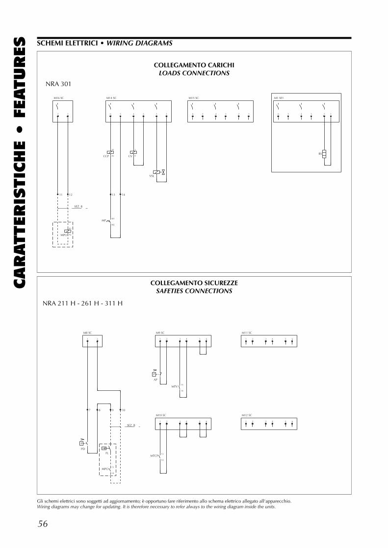
56
CARATTERIS
TIC
HE •
FEATURES SCHEMI ELETTRICI • WIRING DIAGRAMS
Gli schemi elettrici sono soggetti ad aggiornamento; è opportuno fare riferimento allo schema elettrico allegato all'apparecchio.Wiring diagrams may change for updating. It is therefore necessary to refer always to the wiring diagram inside the units.
M16 SC
2
11
SEZ. B
1
12
6 5
14
4 3 2 1
M15 SC
6 5 4 3 2 1
M1 SE1
6 5 4 3 2 1
MPO
CCP
MP
CV
VSL
RS
A1
A2
M14 SC
A1
A2
13
M1
M2
1
0
NRA 301
COLLEGAMENTO CARICHILOADS CONNECTIONS
M8 SC
1
7
P
2
8 9
SEZ. B
1
P
1
2
2
3
3
4
4
5
5
6
6
M11 SC
M12 SC
1
1
2
2
3
3
4
4
5
5
6
6
PDFL
MPO
AP
MTCP
MTV
13
14
10
M9 SC
M10 SC
13
14
13
14
NRA 211 H - 261 H - 311 H
COLLEGAMENTO SICUREZZESAFETIES CONNECTIONS
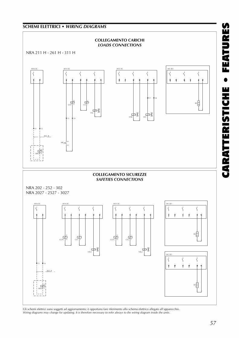
57
CARATTERIS
TIC
HE •
FEATURES
M16 SC
2
11
SEZ. B
1
12
6
13
5
14
4 3 2 1
M15 SC
6 5 4 3 2
17
1
18
M1 SE1
6 5 4 3 2 1
MPO
MP
CCP CV
VSL
VSB VIC
RS
A1
A2
M14 SC
M1
M2
A2
A1
0
1
M16 SC
2
13
SEZ. B
1
14
6 5 4 3 2 1
M15 SC
6 5 4 3 2 1
M1 SE1
M2 SE1
6
6
5
5
4
4
3
3
2
1
2
2
1
1
MPO
CCP1 CV1
VSL1
CCP2 CV2
VSL2
RS
RSA2
A1
M14 SC
A1
A2
1
0
A1
A2
1
0
NRA 202 - 252 - 302NRA 2027 - 2527 - 3027
COLLEGAMENTO SICUREZZESAFETIES CONNECTIONS
SCHEMI ELETTRICI • WIRING DIAGRAMS
Gli schemi elettrici sono soggetti ad aggiornamento; è opportuno fare riferimento allo schema elettrico allegato all'apparecchio.Wiring diagrams may change for updating. It is therefore necessary to refer always to the wiring diagram inside the units.
NRA 211 H - 261 H - 311 H
COLLEGAMENTO CARICHILOADS CONNECTIONS
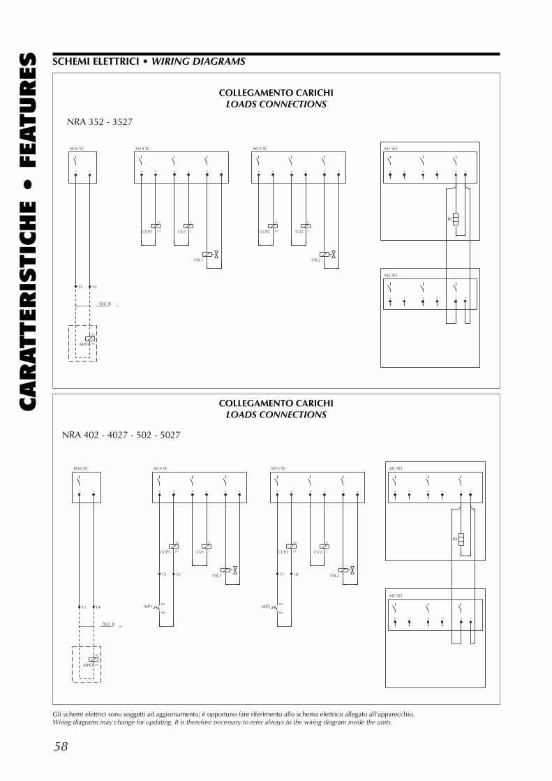
58
CARATTERIS
TIC
HE •
FEATURES SCHEMI ELETTRICI • WIRING DIAGRAMS
Gli schemi elettrici sono soggetti ad aggiornamento; è opportuno fare riferimento allo schema elettrico allegato all'apparecchio.Wiring diagrams may change for updating. It is therefore necessary to refer always to the wiring diagram inside the units.
M16 SC
2
13
SEZ. B
1
14
6 5 4 3 2 1
M15 SC
6 5 4 3 2 1
M1 SE1
M2 SE1
6
6
5
5
4
4
3
3
2
2
1
1
MPO
CCP1 CV1
VSL1
CCP2 CV2
VSL2
RS
A2
A1
M14 SC
A2
A1
0
1
A2
A1
0
1
M16 SC
2
13
SEZ. B
1
14
6
15
5
16
4 3 2 1
M15 SC
6
17
5
18
4 3 2 1
M1 SE1
M2 SE1
6
6
5
5
4
4
3
3
2
2
1
1
MPO
MP1
CCP1 CV1
VSL1
MP2
CCP2 CV2
VSL2
RS
A2
A1
M14 SC
M1
M2
A2
A1
0
1
M1
M2
A2
A1
0
1
NRA 352 - 3527
NRA 402 - 4027 - 502 - 5027
COLLEGAMENTO CARICHILOADS CONNECTIONS
COLLEGAMENTO CARICHILOADS CONNECTIONS
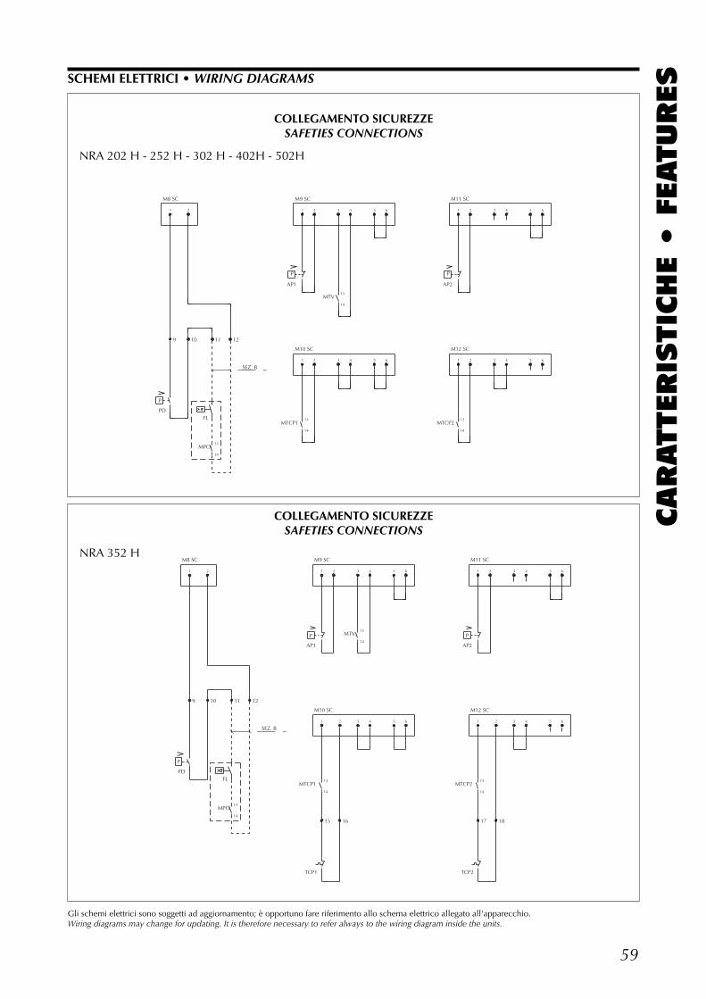
59
CARATTERIS
TIC
HE •
FEATURES
M8 SC
1
9
P
2
10 11
SEZ. B
1
P
1
15
2
2
16
3
3
4
4
5
5
6
6
M11 SC
M12 SC
1
P
1
17
2
2
18
3
3
4
4
5
5
6
6
PDFL
MPO
AP1
MTCP1
TCP1
MTV
AP2
MTCP2
TCP2
13
14
12
M9 SC
M10 SC
13
14
13
14
13
14
NRA 352 H
COLLEGAMENTO SICUREZZESAFETIES CONNECTIONS
SCHEMI ELETTRICI • WIRING DIAGRAMS
Gli schemi elettrici sono soggetti ad aggiornamento; è opportuno fare riferimento allo schema elettrico allegato all'apparecchio.Wiring diagrams may change for updating. It is therefore necessary to refer always to the wiring diagram inside the units.
M8 SC
1
9
P
2
10 11
SEZ. B
1
P
1
2
2
3
3
4
4
5
5
6
6
M11 SC
M12 SC
1
P
1
2
2
3
3
4
4
5
5
6
6
PDFL
MPO
AP1
MTCP1
MTV
AP2
MTCP2
13
14
12
M9 SC
M10 SC
13
14
13
14
13
14
COLLEGAMENTO SICUREZZESAFETIES CONNECTIONS
NRA 202 H - 252 H - 302 H - 402H - 502H
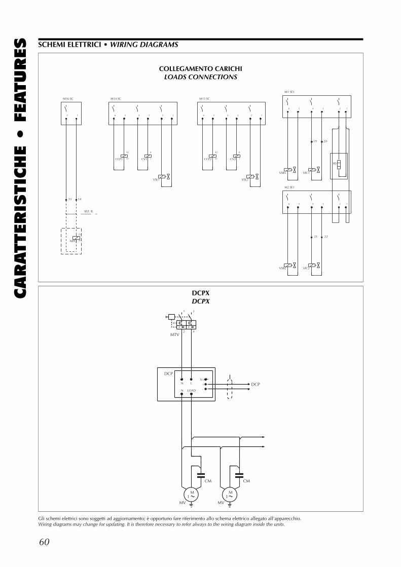
60
CARATTERIS
TIC
HE •
FEATURES
M16 SC
2
13
SEZ. B
1
14
6 5 4 3 2 1
M15 SC
6 5 4 3 2 1
M1 SE1
M2 SE1
6
6
5
5
4
19
4
21
3
20
3
22
2
2
1
1
MPO
CCP1 CV1
VSL1
CCP2 CV2
VSL2
VSB1
VSB2
VIC1
VIC2
RS
A2
A1
M14 SC
A2
A1
0
1
A2
A1
0
1
SCHEMI ELETTRICI • WIRING DIAGRAMS
Gli schemi elettrici sono soggetti ad aggiornamento; è opportuno fare riferimento allo schema elettrico allegato all'apparecchio.Wiring diagrams may change for updating. It is therefore necessary to refer always to the wiring diagram inside the units.
COLLEGAMENTO CARICHILOADS CONNECTIONS
DCP
N
N
M1
L
LOAD
V+
+
-
M1
DCP
MTV
MV
CM
MV
CM
1
2
3
4
DCPXDCPX


I dati tecnici riportati nella presente documentazione non sono impe-gnativi.L’Aermec S.p.A. si riserva la facoltà di apportare in qualsiasi momentotutte le modifiche ritenute necessarie per il miglioramento del prodotto.
Technical data shown in this booklet are not binding.Aermec S.p.A. shall have the right to introduce at any time whatevermodifications deemed necessary to the improvement of the product.
carta riciclatarecycled paperpapier recyclérecycled Papier
Aermec partecipa al Programma diCertificazione EUROVENT.
I prodotti interessati figurano nella GuidaEUROVENT dei Prodotti Certificati.
Aermec is partecipating in the EUROVENTCertification Programme.
Products are as listed in the EUROVENTDirectory of Certified Products.
AERMEC S.p.A.I-37040 Bevilacqua (VR) Italia – Via Roma, 44Tel. (+39) 0442 633111Telefax 0442 93730 – (+39) 0442 93566www.aermec.com - [email protected]