regulation on electric power installations · this energy and its conversion into ... these are...
TRANSCRIPT

REGULATION ON
ELECTRIC POWER INSTALLATIONS
This regulation has been published in the Official Gazette No. 24246 dated 30 November 2000

Regulation On Electric Power Installations
2
CONTENTS
REGULATION ON ELECTRIC POWER INSTALLATIONS
CHAPTER ONE
Purpose, Scope, Legal basis, Application and Definitions
CHAPTER TWO
General Provisions
CHAPTER THREE
Earthings, Protection Methods, Fuses, Miniature Circuit Breakers and Breakers
CHAPTER FOUR
Electric Power Devices
CHAPTER FIVE
Electrical Installations
CHAPTER SIX
Electrical Lines
CHAPTER SEVEN
Provisions Relating to Operational Safety
CHAPTER EIGHT
Provisions Relating to Effectivity

Regulation On Electric Power Installations
3
REGULATION ON ELECTRICAL ELECTRIC POWER INSTALLATIONS
CHAPTER ONE
Purpose, Scope, Reference, Application and Definitions
Purpose and scope
Article 1- This regulation covers the provisions related with the establishment, operation and
maintenance of the electric power installations with safety in terms of human life and material safety.
The following installations are not included within the scope of this regulation:
- Installations included within the scope of Regulation on Internal Electrical Installations,
- Supply and traction lines related with electrically operated vehicles,
- Electrical installations in mining facilities.
However, unless there is a contradictory provision in other regulations related with electricity,
the provisions of this Regulation must be applied.
The relevant Turkish standards constitute the complementary annexes of this regulation. For the
provisions not included in the regulation, standards such as EN, HD, IEC, and VDE must be taken into
consideration. In case of contradiction, priority must be given to the order of listing.
In case of an uncertainty relating to whether any installation will be included within the scope of
this Regulation or not, the decision to be taken about this issue by the Ministry of Energy and Natural
Resources must apply.
Reference
Article 2- This regulation has been prepared in accordance with Article No. 28 of the Law on
the Organization and Duties of the Ministry of Energy and Natural Resources, Law No. 3154.
Application
Article 3- This regulation must be applied on installations to be newly established and to the
parts that are to be modified in the installations have been already established.
In case the execution of any article of this regulation causes difficulties due to local
circumstances or conditions that will prevent technical development, upon the application with
justification to be made to the Ministry of Energy and Natural Resources, the Ministry may permit the
exemption of the application of that article only for that case.
Definitions
Article 4- The definitions have been divided into four as follows; general definitions,
definitions relating to overvoltages in electrical installations, definitions relating to overhead lines and
definitions relating to cable networks.
a) General definitions:
1) The electrical power installations are the installations that may be dangerous in some cases
(approaching, touching etc.) for people, other living creatures and materials and that ensure the
production of electrical energy, changing its characteristics, storage, transmission and distribution of
this energy and its conversion into mechanical energy, light, chemical energy etc.

Regulation On Electric Power Installations
4
2) Low voltage: This is the phase-to-phase voltage having an effective value of 1000 volts or
less than 1000 volts.
3) High Voltage: This is the phase-to-phase voltage having an effective value over 1000 volts.
4) Dangerous voltage: The voltage having an effective value which is higher than 50 volts in
low voltage and of which the value changes depending on the duration of the fault in high voltage.
5) Operation components: These are the devices such as generators, motors, breakers,
disconnectors, switching (connection) cubicles etc. constituting the electrical energy installations.
6) Power plant: The installations where the electrical energy is generated.
7) Grid (Interconnected) network: The mesh network providing the connection of power plants
to one another.
8) Transmission network: The cables and/or overhead line networks that transmits the energy,
produced at certain locations due to the local conditions and collected at the highest level with the
interconnected network, near to the consumer.
9) Distribution network: The network delivering the energy, which is brought to the region of
consumption by transmission, to the consumers.
10) Main Step-down Substations: The transformer substations transfer the energy received from
the interconnected network to lower level transmission networks and also the energy carried to the
distribution region by transmission to the distribution voltage level.
11) Intermediate Step-down Substations: The transformer substations transfer the energy from
one high voltage level to another in networks where two or more high voltage levels are used.
12) Distribution transformer Substations: Those are the transformer substations transfer the high
voltage electrical energy to low voltage electrical energy.
b) Definitions relating to overvoltages in electrical installations:
1) Overvoltage: This is a voltage that occurs generally for short periods of time between the
conductors or between the conductor and the earth that exceeds the highest continuous value permitted
for the operational voltage but not at the operational frequency.
2) Internal overvoltage: This is an overvoltage occurring due to desired or undesired
connection events such as earth contact and short circuits or due to resonance effects.
3) External overvoltage: An overvoltage occurring due to the effect of weather conditions with
lightning.
4) Overvoltage occurring with the effect of other networks: This is the voltage occurring as a
result of the effect of other networks on the subject network.
c) Definitions relating to overhead lines:
1) Overhead line: It is the whole of an installation providing the power transmission consisting
of support points, poles and their foundations, the conductors strung, conductor hardware, insulators,
insulator accessories and earthings.
2) Conductors: Regardless of being live or not, those are the bare or isolated stranded or single
wires between the support points of an overhead line.
3) Aerial insulated cables: Aerial insulated cables are the cables consisting of insulated phase
conductors and insulated or non-insulated neutral conductors which are formed as a single-wire cable
by wrapping on each other or on a messenger or as a multi-wire cable rounded by stranding or cables
consisting of braided conductors.
4) Conductor bundles: The arrangement in which two or more conductors are used instead of a
single phase conductor and the distance between the conductors is approximately the same along the
line.

Regulation On Electric Power Installations
5
5) Nominal section: The section value of the conductors indicated in the standards.
6) Real section: The net section values of the braided conductors without taking into account
the construction tolerances.
7) Conductor failure load: 95% of the theoretical breaking value of the conductors found by
calculation or the value indicated as “failure load” in catalogs.
8) Maximum tensile stress: The maximum horizontal component of the conductor tensile stress
occurring under the additional load base for calculation at -500C or under no load at minimum
environmental temperature or under wind load at +500C.
9) Annual average tensile stress (EDS: Every day stress): The horizontal component of the
conductor tensile stress, which occurs at annual average temperature (generally at +150C) under no
wind condition.
10) Sag: The maximum horizontal distance between the conductor and the line connecting two
suspension points of the conductor.
11) Conductor hardware: The parts that are in direct connection with the conductor and used for
the connection, tensioning and bearing the conductors.
12) Insulator accessories: These are the parts used for connecting the insulators to support points
and to the conductor hardware and for connecting the insulator components to one another.
13) Useful top force of the pole: The permitted horizontal component of other forces referred to
the top, except the wind load on the pole.
14) Span: The horizontal distance between two adjacent poles.
15) Wind span: The arithmetical mean of the ranges on both sides of the pole.
16) Weight span: The horizontal range between the horizontal tangent points of the conductors
on both sides of the pole.
17) Overhead line types:
i) Small span lines: The line of which the distance between two consecutive poles is not
greater than 50 m for bare conductors and 60 m for insulated conductors.
Note: Spans greater than 50 m in small span lines: The greatest span in the small span lines,
which is 50 m, can be increased due to unavoidable reasons. In case a span greater than 50 m is
necessary in small span lines due to topographic reasons, this part must be treated as large span lines.
ii) Large span lines: These are the lines of which the distance between two consecutive poles
exceeds 50 m for bare conductors and 60 m for isolated conductors.
d) Definitions related with cable networks:
1) Energy cables: These are insulated conductors used for the transmission and distribution of
electrical energy that can be laid under the ground when required.
2) Ring cable networks: These are cable networks that end at the other busbar of a step down
substation and mostly operated open at one point.
3) Cable networks supplied from both sides: These are the cable networks of a step down
substation that are terminated at another step down substation and that are generally operated open at a
point.

Regulation On Electric Power Installations
6
CHAPTER TWO
General Provisions
Safety of electric power installations
Article 5- The electric power installations must be constructed so as not to cause any damage to
or constitute a danger on the human life and property under any kind of operation conditions.
It must be impossible to touch the parts of the electric power installations that are under voltage
(active parts) at a distance that may be approached by anybody even if with lack of care and the safety
distances and protection precautions indicated in the following chapters must be provided.
Consideration of facilities which are sensitive to electromagnetic fields
Article 6- The electrical installations must be constructed so that their effects on the facilities
around them, which are sensitive against electromagnetic fields, must be within the permissible limits.
The disturbing electrical and magnetic fields formed by the energy installations must be
attenuated so as to remain within the permitted limits and must be cleaned from high level harmonics.
Protection of nature
Article 7- In the design and construction of the electric power installations, in case there are a
few solutions close to one another from the technical and economic points of view, the one that causes
the least damage on the nature must be chosen.
CHAPTER THREE
Earthings, Protection Methods, Fuses, Miniature Breakers and Breakers
Earthings and protection methods
Article 8-a) The earthings and other methods of protection against indirect touch:
In earthing the electrical power installations, the provisions of the Electrical Installations
Earthing Regulation must be applied. For other protection methods and network type limitations that
may be applied in accordance with the types of networks against indirect contact, the relevant
provisions indicated in the Regulation on Internal Electrical Installations must be taken into
consideration.
b) Precautions to be taken in order to prevent the formation of overvoltages or to attenuate them:
1) In case of internal overvoltage:
1.1) The precautions to be taken against the overvoltages that may occur as a result of earth
contact: For small capacitive earth contact currents less than 3 amperes, the arc disappears by itself
without taking any special precaution. For higher values of the earth contact current, the star point of
the network must be earthed as indicated hereunder.
i) Earthing over the arc suppression coil: Using a reactance coil having an appropriate value,
the current at the point of contact must be lowered to the permanent current value and the arc must be
extinguished. In large networks, in case the permanent current is so high that the arc will not
extinguish, extinguishing must provided by dividing the network.
ii) Earthing directly or over a small ohmic or reactive resistance: In this case, the arc can be
extinguished with automatic re-closing. This method is used for overhead lines. In cable networks, re-
closing relay is not used and re-closing must not be performed.

Regulation On Electric Power Installations
7
1.2) Precautions to be taken against overvoltages that may occur as the result of energizing
events:
i) The following precautions can be taken in relation with the energizing technique about
this issue:
- De-energizing of the transformers, operating with no load, on both sides must be prevented.
- As in the case for transformers and reactance coils, the serially connected inductive resistances
must not either be switched off all together, other than a short circuit condition, and must be switched
off one by one.
ii) The most appropriate precaution to decrease the overvoltages that may occur as a result of
energizing is earthing the star points of the transformers directly or through small ohmic resistances.
iii) The overvoltages that occur as a result of intentional or automatic trip-close operations
can also be decreased with constructive precautions that will be taken at the breakers, disconnectors
and fuses. The overvoltages can be decreased for example by cutting the currents at the moment of
passing through zero, prevention of re-arcing between the contacts or by connecting appropriate
resistances while opening and closing the circuit.
1.3) The precautions to be taken against the overvoltages that occur as a result of resonance:
i) Resonance does not occur in the networks where the star point is earthed directly.
ii) The overvoltages occurring due to the resonance occurring as a result of conductor
breaking are prevented by supplying the breaking point from both sides through the network (such as
dual lines or closed ring lines).
iii) For underground cable networks, the use of surge arrestors is recommended against
internal overvoltages where applicable and use of spark gaps at the locations where no damage will
occur due to arcs.
2) External overvoltages due to the effect of weather conditions:
2.1) Constructive precautions that prevent or limit the occurrence of over voltages:
i) For lines and transformer substations, suitable locations must be chosen where the weather
conditions are good and lightning danger is low. Lines must be routed through brows of hill and
valleys in order to make use of the natural protective characteristics of the locations they will pass.
ii) Conductors of the overhead lines must be protected with sufficient number of earth
conductors on them when required and necessary precautions must be taken in order to prevent the
striking of lightning on the equipment in the operation current circuit. Earth conductor may not be
used in overhead lines up to 36 kV except for locations where the lightning density is high.
2.2) Protective devices such as lightning arresters, spark gaps etc. must be used to provide
protection of the electrical installations and devices against lightning. The use of spark gap is
particularly recommended for installations up to 400 kVA,
3) For overvoltages occurring due to the effect of other networks:
3.1) The precautions to be taken for the overvoltages that occur due to electrostatic or
electromagnetic effects:
i) The distance between the current circuits that may affect one another must be kept as long
as possible. In order to cancel the electromagnetic effect, the current circuits must be transposed.
ii) The voltage to be induced on cable lines that will affect one another may be decreased by
using special metal shields and by dividing the circuits into short parts using isolation transformers.
Note: Isolation transformer is a transformer used for energy transmission between systems
having different potentials, the primary and secondary windings of which are separated from each
other.

Regulation On Electric Power Installations
8
3.2) Precautions to be taken in order to prevent direct passage of voltage from one network to
the other: For this purpose, only the following constructive precautions must be taken:
i) Provision of sufficient level of insulation at the approaching areas and between two
networks.
ii) Compliance with requirements relating to the approaching lines and their intersection.
For the distances to provide sufficient insulation, the voltage arc distances and overhead system
insulation distances must be in compliance with the provisions indicated in the relevant Turkish
Standards (TS 855, TS 4238, TS 8800 and other relevant Turkish Standards).
4) The value of the pulse earthing resistance must be examined in terms of compliance with
the value calculated with the method indicated in the Electrical Installations Earthing Regulation.
c) Precautions to be taken against overcurrent effects:
All parts of the installations, whatever the operation conditions are, must be arranged and
dimensioned so as to prevent the occurrence of any danger for the people, occurrence of fire or
occurrence any damage to the installations with the effect of the highest short circuit current, including
the moment of short circuit current clearance.
Each protection device must ensure the protection of the operation component in the front zone
of it and must be adjusted in accordance with the nominal values of such equipment and, if necessary,
must be able to perform back-up protection duty for the operation components in the subsequent zone.
Total clearance times of the zones of the protection relays must be adjusted on nominal short
circuit current withstand periods that are proven with type tests of the operation components being
used.
Continuous value of the short circuit current must be taken into consideration for heating and the
highest transient pulse value must be taken into consideration for electrodynamics effects.
The current for operating the overcurrent protection relays must be adjusted in accordance with
the minimum fault current that may occur. In installations where earth fault current is smaller than the
load current, the relays must be equipped with measuring circuits that will discriminate those two
currents or the earthing resistance of the installation must be installed in such a way that the minimum
fault current should be higher than the load current.
Fuses, miniature breakers and breakers:
Article 9- As a general rule, protection of the electrical equipment at the installations against
overcurrents shall be provided with fuses or breakers. Fuses, miniature breakers and breakers must be
chosen at a capacity to securely clear the highest short circuit current where they are located. Fuses
that are bridged or patched by winding a wire must not be used.
The protection arrangement against over currents must be placed so as to ensure the clearance of
the currents of all the conductors exposed to danger in case of failure. On the other hand, in earthed
systems, the earthing installations must not be disconnected from the system during the operation of
the protection device against overcurrents and the earthing system resistance must not be increased.
For this type of equipment, all type test reports obtained from recognized independent
(accredited) laboratories must be present.

Regulation On Electric Power Installations
9
CHAPTER FOUR
Power System Electrical Devices
Protection of devices against arcs and sparks
Article 10- Power system electrical devices must be constructed or arranged so that the arcs and
sparks that may occur during their use or operation will not be dangerous for the people and for the
property. This condition must be verified with type tests indicated in the current Turkish Standard (TS)
for each device used (in case there are no such TS, in EN, HD, IEC, VDE, respectively).
In order to minimize the fire hazard that may be created with arcs that may occur in the fused
disconnectors at the locations having fire hazard, crushed stone must be laid or lean concrete of 10 cm
thickness must be applied on a region having a radius of 3 meters.
Heating of devices under continuous load
Article 11- Power system electrical devices and their connection components must be
constructed and arranged so that when they are continuously loaded with the nominal current, they
will not exceed the maximum temperature increases indicated in the temperature increase tests
included in the relevant standards.
The devices having high temperatures which may not be harmful for themselves but may be
dangerous when passed to other devices must be constructed and arranged so that fire hazard will not
be present for the flammable instruments around them.
Insulation of the parts of live devices
Article 12- The live parts of the power system electrical devices must be isolated from the earth
and among themselves in a reliable and continuous manner taking into account the local conditions
and the operation voltage.
Protective enclosures of devices
Article 13- The enclosures constructed in order to prevent random contact with the live parts of
the electrical devices must be resistant against the mechanical stresses that may come from the interior
and exterior and must be so as to make a maneuver even if an arc occurs in the device.
These protective enclosures must have a protection class appropriate for the conditions of the
location where the device is located. The definition of the protection class is as indicated in the
relevant standard.
Arrangement of devices
Article 14- The devices on which maneuvers will be made during operation and the
measurement devices will be read must be placed at the locations that can be easily accessed without
any danger and must be easy to use.
Control lever handles of fuses, disconnectors and breakers to be used in the energizing
installations that are controlled with hand or with insulated pliers or similar instruments must be
placed at an appropriate height. However, this height must be minimum 50 cm. maximum 170 cm
over the ground where operators stand during the maneuver.
This height may be increased as necessary at outdoors installations.
Regulation On Electric Power Installations
10
Control arrangements of devices
Article 15- The control arrangements of the electrical devices must withstand the external forces
that may be formed during use and the internal forces that may occur in case of a fault without harmful
deformation. Those must also be arranged so as not to contact with the live parts in case of a failure.
Arms, wire ropes and strings related with the carrying organs must be arranged and protected so
as not to contact with the live parts of the installation in case of breaking.
Locations of breakers, disconnectors and load disconnectors
Article 16- The breakers and the disconnectors must disconnect the circuit completely and
securely under any kind of weather conditions. Here, it is not compulsory to see the locations of the
main contacts.
The open and closed positions of those devices must be distinguished with safely arranged
position indicators.
Especially the ultimate positions must be marked so as not to allow any mistake.
Protection of auxiliary current circuits against overcurrents
Article 17- As a general rule, fuses must not be installed on the current circuits of auxiliary
devices such as electro-magnets, relays etc. which operate main automatic devices with an auxiliary
current. In case their use is necessary in terms of operation technique, those circuits and fuses must be
capable of carrying a few times the auxiliary current continuously.
Connection of devices to the protection earthing
Article 18- There must be the means of connecting the metal-body and protective enclosures of
the electrical devices to the earthing conductor.
Inscriptions on the devices
Article 19- There must be indelible, undeformable, easily seen writings or markings on all
electric power devices, measurement transformers, measuring equipment and fuses as well as all
circuit breaker devices, showing all marking information indicated in the relevant standards.
CHAPTER FIVE
Electrical Installations
Arrangement of installations
Article 20- Installations must be arranged in an open manner so as to be monitored in a fast and
reliable way within a short period of time for operation as well as repair and maintenance. All
important installation parts and devices must easily be accessible; it must be possible to install them
without any difficulty or to take them out. In case there are different voltage and current types within
the same installation, the installation parts related with them must be collected in the form of separate
groups and must be separated from each other in terms of location.
Installations must be arranged in sections so that the operation can be continued without
interruption as much as possible in case various parts are switched off due to failure, repair and
maintenance reasons. It must be possible to make the switched off installation parts or instruments free
of voltage with appropriate and easily seen disconnection devices.
While the installations are being constructed, it must be taken into account the operation will
continue during the future expansions and construction works.

Regulation On Electric Power Installations
11
Warning plates
Article 21- Indelible writings, marks and schematics must be placed at various locations and
installation parts in order to allow the personnel clearly understand what the machines, devices and
conductors are used for.
Furthermore, the following signs must be placed at appropriate locations in the electrical
installations:
1) Instructions related with first aid to be made in case of accidents caused by electric current,
2) Connection diagram of the installation,
3) Short instructions related with special precautions that must be taken during the operation of
the installation.
Flammable tools
Article 22- Flammable tools may be used by arranging them so as not to cause any fire and
smoke hazard or by covering them with a non-flammable cover. No wooden tools may be used within
the electrical installations except in sections adjacent to the installation such as dwellings etc.
In dwellings and structures used for other purposes, especially the sections where oil transformer
is located must be separated from other structure sections so as to be fire-resistant and to prevent the
spread of a possible fire. All doors must be opened outwards and must be made of sheet steel and
protection arrangements that act rapidly against the internal failures of the transformers must be used.
Illumination
Article 23- All installation parts must be well illuminated with daylight as much as possible.
Furthermore, sufficient and evenly distributed electrical illumination facilities must be constructed in
those parts. In cases where the electrical illumination facility is not usable, special illumination
facilities must be established in order to perform the necessary works and to walk around the
supervision and maneuver locations without any danger.
The installed illumination installation must provide minimum 250 Lux level in HV cubicles and
LV switchbord rooms and minimum 150 Lux illumination level in transformer rooms. Sufficient
number of battery powered emergency lamps (at least one) must be provided at transformer
substations at each location, or battery powered illumination lamps must be provided if sufficient
battery capacity exists. Those lamps must be arranged so as to switch on automatically in case of
power failures at continuously manned locations. At other locations, lamps must be turned on
manually with an appropriate precaution.
Flooring
Article 24- The flooring near the moving machine parts and the live installation parts must be
made so as to prevent the sliding and stumbling of people. In case this is not possible, additional
protective precautions must be taken so as to prevent contact with the live or moving installation parts.
The surface coating must be made of materials that will not cause dusting. Covers of the high voltage
conduits in the flooring must be installed so as not to pop up from their places due to internal pressure
occurring during any failure.
Using the places of high voltage installations for different purposes
Article 25- The places reserved for high voltage installations and being operated can not be used
for storing things (except maneuver handles, insulation gloves and similar) or for any other purposes.
Operation and maintenance devices
Article 26- All instruments used in operation (maneuver handles, fuse pliers, insulated gloves,
insulated tables etc.) must be checked at the periods indicated in their standards, or if there is no such
standard, at the periods envisaged by their manufacturers and kept under maintenance and repair.
These checking operations must be recorded permanently.

Regulation On Electric Power Installations
12
In case different levels of voltages are present within an installation section, the tools in that
section must withstand the highest voltage to prevent any possible harm as a result of wrong usage of
the tools.
Maintenance and repair
Article 27- The maintenance and repair of the installations and instruments must be performed
at the intervals indicated in their technical documents. The maintenance and repairs performed must be
recorded permanently.
Placement and protection of electrical operation devices
Article 28- The electrical operation devices must be placed so that their operation, maintenance
and repair can be performed without any danger. The places occupied by the operational personnel and
the passages should always be left empty.
The operation tools and their protection arrangements should be constructed in such a way that
possible random contacts should be impossible at the sections in which a voltage of 250 V and above
is present.
Starting and spreading of fire in the electrical operation devices must be prevented as much as
possible with suitable arrangements.
Low voltage parts in insulated high-voltage operation devices
Article 29- The low voltage circuits in contact with high voltage machinery and tools insulated
against earth must be treated as high voltage installation parts in terms of their arrangement and the
work performed by them.
This article is especially applied to the direct current serial machines, rectifiers, capacitors etc.
While working near the machinery insulated against earth, care must be paid for the manual use of
especially portable hand lamps, flexible cables, crane strings etc.
Ventilation of batteries and their rooms
Article 30- When the use of batteries is necessary, they must be maintenance-free or dry type
batteries. Capacities of the batteries must be sufficient for the period necessary for the consumers
supplied by them for the period as required by the operation.
At locations where dry type batteries are used, it is not necessary to take any additional
precautions for ventilation and no separate battery room is necessary. When the life of the existing
lead acid batteries is over, they must be replaced with maintenance-free or dry type batteries.
Characteristics of the lead – acid battery rooms
Article 31 – Lead-acid battery rooms must have dry air, they must be cool and free from
vibration. They must not be subject to temperature variations. Batteries must be protected against very
high and very low environmental temperatures.
Lead – acid battery rooms must be free from freezing danger as much as possible and heating
must not be necessary. Lead acid battery rooms must never be heated with open fire or heater wires.
The temperatures of the lead acid battery units must not be different from one another. The
windows of the battery rooms that are easily accessible from outside such as close to pedestrian
pavements, for example, must be protected with dense wire cage or wired glass.
In lead acid battery rooms, the doors and windows must be opened outwards. Doors, window
frames, walls, ceilings, floors and the floors on which batteries are placed must be resistant against
electrolytic effect. When necessary, protective paints must be used against this effect.
Conductors, cables and electrical operation tools suitable for humid and similar locations must
be used for the electrical installations in lead – acid battery rooms. At these locations, incandescent
lamps and waterproof type armatures must be used and fans having collectors that may cause arcs
must not be used.

Regulation On Electric Power Installations
13
The electrical tools that produce sparks such as switches, sockets etc., which may cause flaming
must be placed out of the battery rooms.
Harmful gases such as ammonia must not be present in lead – acid battery rooms.
An adjacent section must be provided to keep the tools necessary for the lead – acid batteries
and a wash basin must be installed there.
The locations where the batteries are placed must preferably be constructed so that natural
ventilation will be sufficient.
In case the air necessary for ventilation can not be provided through windows, doors, etc., non-
sparking fans, ventilation pipes or ducts and similar artificial ventilation devices must be used. These
pipes and ducts must be resistant against the electrolyte effect and must not be open to smoke
chimneys or fire (furnace, etc.) places.
Replacing the batteries
Article 32- The batteries must be placed so as to be easily accessed and checked. The
ventilation condition must be taken into consideration for placing the batteries.
In case the batteries are placed on one or more shelved racks, appropriate distances must be left
between them for the performance of the necessary works.
Each battery unit must be insulated against the floor and the earth. The insulating supports, to
which the lead – acid batteries are fixed must be resistant against electrolytes.
Lead – acid batteries may be placed as follows:
- On the floors made of stone, brick or concrete, or on insulators resistant against electrolytes
which are placed on smooth surfaces,
- On shelves. In this case, the shelves must be resistant against the electrolyte effects. The
locations under the shelves must be cleanable. In the battery installations, the passage widths must
have the size explained in Article 35 – b/1. The ceiling height of these passages must not be less than 2
m.
Battery connection conductors
Article 33- The connections between separate sets in lead – acid battery rooms or between the
panel and the room must be made with insulated conductors or cables resistant against electrolytic
effects.
The voltage at the DC side of battery installations must be disconnected by removing the
connections at both of the poles.
Protection of personnel
Article 34- It must be ensured that the people in charge are careful against the danger of the
existing lead – acid battery operation and the following precautions must be taken in order to protect
those people against hazards:
1) No fires must light including matches and lighters,
2) Tools that may cause sparks must not be used,
3) Mobile phones must be turned off,
4) When acid and/or acidic water is contacted, the contacted organs must immediately be
washed with clean water,
5) In case of presence of accumulated gas inside, the location must immediately be left,
6) The recommendations related with general and specific security of work must be complied
with.
Regulation On Electric Power Installations
14
Construction of installations inside the building
Article 35- a) Minimum air clearances:
1) The minimum clearances to be used in the switching installations, for which the insulation
capability tests are performed within the building, are shown in Table 1.
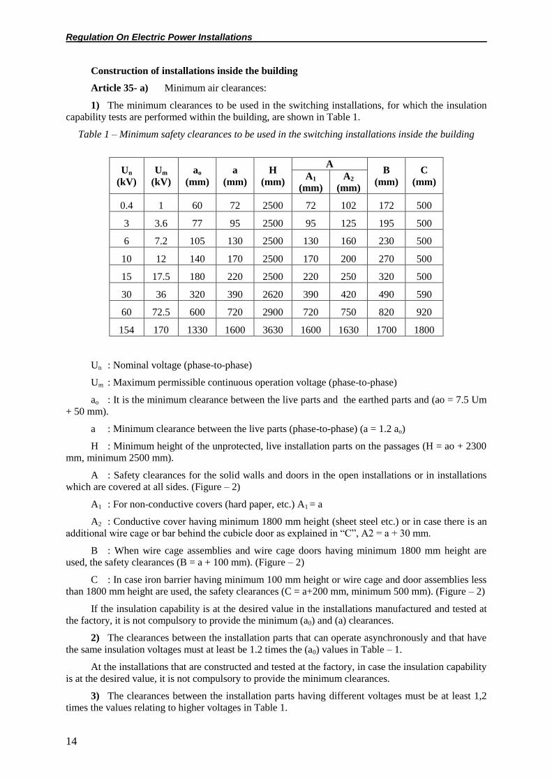
Table 1 – Minimum safety clearances to be used in the switching installations inside the building
Un
(kV)
Um
(kV)
ao
(mm)
a
(mm)
H
(mm)
A B
(mm)
C
(mm) A1
(mm)
A2
(mm)
0.4 1 60 72 2500 72 102 172 500
3 3.6 77 95 2500 95 125 195 500
6 7.2 105 130 2500 130 160 230 500
10 12 140 170 2500 170 200 270 500
15 17.5 180 220 2500 220 250 320 500
30 36 320 390 2620 390 420 490 590
60 72.5 600 720 2900 720 750 820 920
154 170 1330 1600 3630 1600 1630 1700 1800
Un : Nominal voltage (phase-to-phase)
Um : Maximum permissible continuous operation voltage (phase-to-phase)
ao : It is the minimum clearance between the live parts and the earthed parts and (ao = 7.5 Um
+ 50 mm).
a : Minimum clearance between the live parts (phase-to-phase) (a = 1.2 ao)
H : Minimum height of the unprotected, live installation parts on the passages (H = ao + 2300
mm, minimum 2500 mm).
A : Safety clearances for the solid walls and doors in the open installations or in installations
which are covered at all sides. (Figure – 2)
A1 : For non-conductive covers (hard paper, etc.) A1 = a
A2 : Conductive cover having minimum 1800 mm height (sheet steel etc.) or in case there is an
additional wire cage or bar behind the cubicle door as explained in “C”, A2 = a + 30 mm.
B : When wire cage assemblies and wire cage doors having minimum 1800 mm height are
used, the safety clearances (B = a + 100 mm). (Figure – 2)
C : In case iron barrier having minimum 100 mm height or wire cage and door assemblies less
than 1800 mm height are used, the safety clearances (C = a+200 mm, minimum 500 mm). (Figure – 2)
If the insulation capability is at the desired value in the installations manufactured and tested at
the factory, it is not compulsory to provide the minimum (a0) and (a) clearances.
2) The clearances between the installation parts that can operate asynchronously and that have
the same insulation voltages must at least be 1.2 times the (a0) values in Table – 1.
At the installations that are constructed and tested at the factory, in case the insulation capability
is at the desired value, it is not compulsory to provide the minimum clearances.
3) The clearances between the installation parts having different voltages must be at least 1,2
times the values relating to higher voltages in Table 1.

Regulation On Electric Power Installations
15
4) In case the clearances of the connection points of the devices or insulators to the earth are
shorter than the (a0) clearances given in Table 1, the provisions in (i and ii) below must be applied.
i) The devices and insulators dimensioned in accordance with the test voltage must be
connected to the tested connection points in accordance with the relevant assembly instructions.
ii) When the insulation abilities are verified, for example with the model test, smaller
clearances may be used, especially on the insulator intermediate parts and isolated conductors.
b) Passages and doors
1) Width of the passages:
The width of the passages and entrances must be sufficient for moving easily and for carrying
the devices. Passage widths must not be less than the values given in Table 2 and the control systems,
projecting parts such as withdrawable connection facilities at the separation points must not narrow the
passages.
For the installations having a voltage up to 250 V against earth, the values given in Table 2 may
be decreased by 20 cm.
For large installations, wide passages are recommended.
In fully closed installations, the clearance of the assembly locations with the behind wall must
be minimum 60 cm.
Fully closed systems that are operated from the front may fully be leaned to the wall if pressure
discharge arrangements are provided.
2) Height of the passages:
i) At the locked electrical operation locations, the height of the bare, unprotected live parts
from the floor must be as high as (H) given in Table 1.
ii) If there is no protection device at the electrical operation locations of locked door type, the
upper edge of the earthed insulator base iron must have a height of minimum 2300 mm from the floor
(Figure 3).
3) Exits and doors of locked electrical operation locations:
i) Exits and doors must be arranged so that the length of the route inside the installation
providing exit to outside in emergency conditions will not exceed 20 m and exit doors must be
constructed on both sides of the corridors.
Fixed ladders and slides may be used. For the installations inside the building having voltages of
60 kV or higher, exit routes must be constructed to provide exit in emergency conditions not
exceeding 40 m in length.
ii) Door locks must be assembled so as to prevent the entrance of unauthorized persons, but not
to prevent the people within the installation from exiting.
This condition is considered to be complied with only in case the building entrance doors and
the doors providing exit in emergency conditions can be opened from the outside only by using a safe
key (not slot).
It must be possible to open these doors with a latch or similar simple device without using a key
from the inside even if they are locked from outside.
iii) In case the area in front of the door is open for general traffic, the doors must be made of
flame-resistant or nonflammable materials.
iv) Free height of the doors must be minimum 200 cm and their free width must be minimum
70 cm.
v) Ventilation holes must be constructed so as to prevent contact with the live parts and to
prevent the ingress of foreign materials.

Regulation On Electric Power Installations
16
Table 2 – Minimum widths in the installations within the structure (F) (See Figure 1)
Purpose of use of the passages or
entrances
Passage width
One side of the passage is live
(mm)
Both sides of the passage are live
(mm)
Control F1= 1000 F2= 1200
Manual operation (maneuver) F3 = 1200 F4= 1400
Figure 1: Passage widths when the cubicle faces are wire cage door and solid wall
c) Cubicles, connection cabinets, switchboards, etc.
In the switching cabinets, switchboards, etc. all passage and entrance electrical conductors must
be connected in a very clear and understandable way and easily disconnected. It must be possible to
check the connection ends easily.
The upper parts of the cubicles, connection cabinets and connection frames which are closed on
all sides and having a height less than 220 cm must be closed.
d) Protection against contact and random contact:
1) Installations inside the structures must be constructed with locks to prevent the entry of
unauthorized persons.
2) The clearances (A), (B) or (C) indicated in Table – 1 must be left between the protection
installations and bare live installation sections (Figure – 1)
3) For the protection of the people working during operation in the installation sections, the
installations must be constructed so that the protection can be applied.
In case of using insulating plates for the protection indicated above, then those plates must be
fixed so that their condition will not change in a dangerous way in case of wrong operations (such as
striking). The plates must not directly be in contact with the live parts.
Regulation On Electric Power Installations
17
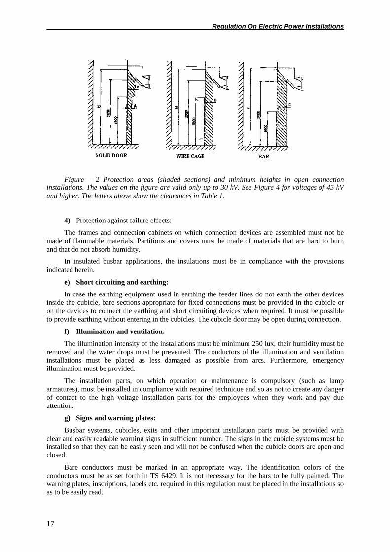
Figure – 2 Protection areas (shaded sections) and minimum heights in open connection
installations. The values on the figure are valid only up to 30 kV. See Figure 4 for voltages of 45 kV
and higher. The letters above show the clearances in Table 1.
4) Protection against failure effects:
The frames and connection cabinets on which connection devices are assembled must not be
made of flammable materials. Partitions and covers must be made of materials that are hard to burn
and that do not absorb humidity.
In insulated busbar applications, the insulations must be in compliance with the provisions
indicated herein.
e) Short circuiting and earthing:
In case the earthing equipment used in earthing the feeder lines do not earth the other devices
inside the cubicle, bare sections appropriate for fixed connections must be provided in the cubicle or
on the devices to connect the earthing and short circuiting devices when required. It must be possible
to provide earthing without entering in the cubicles. The cubicle door may be open during connection.
f) Illumination and ventilation:
The illumination intensity of the installations must be minimum 250 lux, their humidity must be
removed and the water drops must be prevented. The conductors of the illumination and ventilation
installations must be placed as less damaged as possible from arcs. Furthermore, emergency
illumination must be provided.
The installation parts, on which operation or maintenance is compulsory (such as lamp
armatures), must be installed in compliance with required technique and so as not to create any danger
of contact to the high voltage installation parts for the employees when they work and pay due
attention.
g) Signs and warning plates:
Busbar systems, cubicles, exits and other important installation parts must be provided with
clear and easily readable warning signs in sufficient number. The signs in the cubicle systems must be
installed so that they can be easily seen and will not be confused when the cubicle doors are open and
closed.
Bare conductors must be marked in an appropriate way. The identification colors of the
conductors must be as set forth in TS 6429. It is not necessary for the bars to be fully painted. The
warning plates, inscriptions, labels etc. required in this regulation must be placed in the installations so
as to be easily read.
Regulation On Electric Power Installations
18
Insulated bars and clips, voltage checking instruments, earthing and short circuit assemblies
must be kept at a dry location that can be entered easily.
h) To prevent reverse supply during the maneuvers and to provide safety, it is recommended to
use loop interlock devices in accordance with the maneuver order.
i) Metal enclosed type cubicles/switching and control installations, type tested according to the
related standards, shall be used in the high voltage installations that will be newly constructed up to a
maximum operation voltage of 36 kV (36 kV included), following a transition period of two years
starting from the date of effectiveness of this regulation.
Construction of outdoor type installations
Article 36-a) Minimum air distances:
1) The minimum distances to be used for the outdoors installations are shown in Table 3.
2) The distances between the installation sections that can work asynchronously and that have
the same insulation voltages must be minimum 1,2 times the (a0) values given in Table 3.
Meanings of the letters used in Table 3:
Un : Nominal Voltage (phase-to-phase),
Um : Maximum permitted continuous operation voltage (phase-to-phase),
ao : Minimum distance between the earthed sections and the live parts (a0= 7,5.Um + 50 mm,
but minimum 100 mm).
a : Minimum distance between the live parts (phase-to-phase) (a = 1,2a0 mm, but minimum
100 mm).
H1 : Minimum height of the live sections from the floor (H1= a0 + 2400 mm, but minimum 2500
mm),
H2 : Minimum height of the live sections from floor in the sites, streets etc. (H2 values shall be
taken from Table 8),
A : Minimum safety distance between the external wire fences and the devices (A= a0 + 1800
mm). In this distance, live sections may not be placed at a height less than 6 m,
B, C : Minimum distance between tall devices placed directly on the earth and the protection
devices (obstructions) around such devices (Figure – 4).
In case protection devices having a minimum height of 1800 mm are used, B= a0 + 100 mm, but
must be minimum 600 mm. In case protection devices having a minimum height of 1000 mm are used,
C = a0+ 1250 mm.
Regulation On Electric Power Installations
19
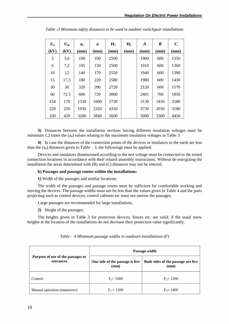
Table -3 Minimum safety distances to be used in outdoor switchgear installations
Un
(kV)
Um
(kV)
ao
(mm)
a
(mm)
H1
(mm)
H2
(mm)
A
(mm)
B
(mm)
C
(mm)
3
6
10
15
30
60
154
220
330
3,6
7,2
12
17,5
36
72.5
170
250
420
100
105
140
180
320
600
1330
1930
3200
100
130
170
220
390
720
1600
2320
3840
2500
2500
2550
2580
2720
3000
3730
4330
5600
1900
1910
1940
1980
2120
2401
3130
3730
5000
600
600
600
600
600
700
1430
2030
3300
1350
1360
1390
1430
1570
1850
2580
3180
4450
3) Distances between the installation sections having different insulation voltages must be
minimum 1,2 times the (a0) values relating to the maximum insulation voltages in Table 3.
4) In case the distances of the connection points of the devices or insulators to the earth are less
than the (a0) distances given in Table – 3, the followings must be applied:
Devices and insulators dimensioned according to the test voltage must be connected to the tested
connection locations in accordance with their related assembly instructions. Without de-energizing the
installation the areas determined with (B) and (C) distances may not be entered.
b) Passages and passage routes within the installations:
1) Width of the passages and similar locations:
The width of the passages and passage routes must be sufficient for comfortable working and
moving the devices. The passage widths must not be less than the values given in Table 4 and the parts
projecting such as control devices, control cabinets etc must not narrow the passages.
Large passages are recommended for large installations.
2) Height of the passages:
The heights given in Table 3 for protection devices, fences etc. are valid, if the usual snow
heights at the location of the installations do not decrease their protection value significantly.
Table – 4 Minimum passage widths in outdoors installations (F)
Purpose of use of the passages or
entrances
Passage width
One side of the passage is live
(mm)
Both sides of the passage are live
(mm)
Control F1= 1000 F2= 1200
Manual operation (maneuver) F3 = 1200 F4= 1400

Regulation On Electric Power Installations
20
i) The minimum height of the unprotected, bare live sections on the surfaces used for walking
must be as (H1) in Table 3 if they are not surrounded with fences (Figure – 3).
ii) The minimum (a0) clearances in Table 3 must be provided between the live parts and the
highest point of the device for transportation of devices in the installations, but this clearance must not
be less than 500 mm.
iii) The upper edge of the earthed steel base of an insulator of a device not surrounded with a
protection device must be at a minimum height of 2300 mm from the ground at all voltages (Figure –
3).
Figure – 3: The heights of the conductors on the surfaces for walking, not surrounded with fence
in the installation (in accordance with Table 3).
c) Protection against contact or random contact:
1) Outdoors installations must be constructed with locks to prevent the entry of unauthorized
persons.
2) The protection arrangements in installations surrounded with fences: Solid walls and wire
cages must have a minimum height of 1800 mm.
3) The protection area in the installations (Figure 4): Safety distances (B) and (C) of Table 3
must be left between the protection arrangements (meshed wire, barrier etc.) around the devices and
the devices in the installation.
Figure 4- Protection area and minimum height (H1) in the installation
4) Outer fence and protection area of the outdoor installations (Figure 5, 6, 7)
i) The circumference of the outdoor installations must be surrounded with fence having a
minimum height of 1800 mm and a warning plate against high voltage installations on it.

Regulation On Electric Power Installations
21
Figure-5 Protection area of the
devices on support
Figure-6 Protection area of the
devices placed on earth and
having normal fence without
passage
Figure-7 Protection area of
the devices placed on earth
having normal fence with
passage.
ii) On the entrance doors of the outdoor installations, locks that can be opened with bit key or
safety key and warning plates must be installed.
iii) A protection area having safety clearances given in Table 3 must be left inside the outer
fence in the outdoor installations (The shaded areas in Figures 5, 6, 7).
The distance to the outer fence of the devices that are placed directly on the earth can not be less
than the (C) values given in Table 3 (Figure 6). But the shaded areas can not be entered before de-
energizing the installation.
iv) In case there is a passage between the outer fence and the device near it, a distance of (B1 +
F) or (C2 + F) must be left between the device and the outer fence (Figure-7).
5) No fence is necessary for installations and operation devices which are closed at all sides.
d) Short circuiting and earthing:
In case the earthing equipment used for earthing the feeder lines do not earth the other devices in
the cubicle, bare sections appropriate for fixed connections must be provided in the cubicle or on the
devices to connect the earthing and short circuiting devices when required.
e) Supports, conductor fittings, insulators:
The load calculation of the supports and portals and the dimensioning of the conductor
equipment, insulators and insulator connection parts of the outdoor installations are performed in
compliance with the principles applied to the overhead lines.
f) Illumination:
The illumination level of the installations must be minimum 60 lux. The conductors of the
illumination installation must be laid so as not to be endangered because of arcs as much as possible.
The installation parts, on which operation or maintenance is compulsory (such as lamp
armatures), must be installed in compliance with the technique and so as not to create any danger of
contact to the high voltage installation parts for the employees when they work and pay due attention.
g) Signs, warning plates:
Busbar systems, outlets, transformers and other important installation sections must be marked
with easily readable signs as indicated in TS 6429.

Regulation On Electric Power Installations
22
The warning plates, warning signs, labels etc required in this regulation must be placed in easily
readable locations in the installations.
Transformer substations
Article 37- a) Ventilation of distribution transformers:
1) Necessary precautions must be taken for the ventilation of the transformers. A sample
figure, other than the special conditions for the ventilation of distribution transformers (compact
transformer substations, etc), is given below.
At locations where this solution can not be applied (under special conditions) forced or special
natural ventilation must be provided.
The air input may also be provided by other means (e.g. providing the ventilation using the
waste oil reservoir at the bottom of the transformer).
2) A sample calculation method for the shutter dimensions necessary for natural ventilation is
given below.
H : Height difference (m) between the horizontal axis of the transformer tank and horizontal
axis of air outlet shutter
P : Total loss of transformer (kW)
AL : Area of air outlet shutters (m2):
AL is calculated as AL = 0.188P/√H. But it is recommended to have the area of the exit shutter
to be 10% higher than the calculated (AL) value.
3) At locations where forced ventilation is made, thermostat control is necessary. The
environmental temperature of the transformer room must not exceed 400C.
5) The shutter wire cages must consist of meshes of maximum 0.5 x 0.5 cm2 in order to prevent
the entrance of foreign materials and living creatures.
b) Transformer waste oil reservoir:
a- Cable
b- Grating with gravel on top
c- Air outlet shutter (wire caged)
d- Platform
e- Air inlet shutter (wire caged)

Regulation On Electric Power Installations
23
Sample Figure: A sample Distribution Transformer Cubicle (the given shape is not compulsory
and is included only for information).
For the oil transformers having an oil volume up to 1500 l, an oil collection chamber may be
constructed with a volume sufficient to contain all the oil or the earth having a threshold at an
appropriate height and impermeable to oil may be used for this purpose. For the oil transformers
having an oil volume exceeding 1500 l, waste oil reservoir shall be constructed under or out of the
transformer section (as shown in the sample figure). The volume of the part of that reservoir, where oil
is collected under the galvanized steel grating must be same as the oil volume and gravel with 5 cm
thickness must be provided on the oil grating.
Connection of the waste oil reservoirs in or out of the building to the sewage network, earth,
streams, rivers, lakes or sea is strictly prohibited.
c) Transformer rooms:
1) The transformers must be placed at a minimum distance of 60 cm to the walls.
In case there are doors (covers) in equal width to that of transformer and opening in two sides,
that distance may be reduced to 30 cm (for providing air circulation). The distance between the top
point of transformers and the ceiling must be minimum 60 cm, up to 36 kV.
For compact transformer substations, this paragraph (c.1) does not apply. The arrangement is
done according to the conditions indicated in the relevant specifications and related standards.
2) Steps in the flooring in transformer rooms are prohibited. The internal surfaces of the room
must be coated with a material that will not create dust. Paint shall not be applied on the ceilings.
d) The electrical connections of the transformers must be made so as not to be contacted by
accident.
e) The insulation of the electrical connections of the high voltage bushings of the transformers
used in the building must be provided with proper material for the applied voltage or with modular
type.
f) The transformers may be installed under the ground, in basements or on top floors of multi
storey buildings. Precautions against humidity, ventilation and flood must be taken for the
transformers installed underground and in the basements.
In the case of placement and, when necessary, replacement of the transformers, their weight and
largest dimensions must be taken into consideration and the necessary precautions must be taken.
g) The transformers in the main building, of all the structures in which densely populated people
are present and also the basements, high-storey buildings, hospitals, theaters, shopping centers,
schools and similar buildings which are supplied independently, must be of dry type for safety
reasons.
h) Following the expiry of the two-year transition period of this regulation, the largest external
dimensions of the transformers having primary voltage up to 36 kV (including the not separable
hardware constituting the whole), with A (cm) being the length of the transformer, B (cm) being the
width of the transformer, C (cm) being the height of the transformer, must not exceed the following
values for transformers having a capacity up to 630 kVA: A= 170 cm, B= 135 cm, C = 195 cm; for
transformers having power up to 1600 kVA: A = 210 cm, B = 185 cm, C= 245 cm, for transformers
having power up to 2500 kVA: A= 230 cm, B = 215 cm, C= 265 cm.
i) Earthquake loads:
The horizontal earthquake loads must be taken into consideration in the construction of the
transformer substations. The earthquake loads that may occur in the earthquake regions must be
calculated with the formula F= C.W, where,
F: force acting on the center of gravity of each member (kg – force),

Regulation On Electric Power Installations
24
W: mass of the steel part or electrical equipment (kg – mass),
C: 0,5 g (g= 9,81 m/sn2, which is the gravitational acceleration).
The steel part and the electrical equipment in the transformer substations must be based on the
forces to be calculated with the formula given above. Especially the insulators and their connection
points must be examined.
Switching arrangement of distribution transformers
Article 38- A main circuit breaker which shall break the circuit sensing both the thermal and
magnetic effect of the current must be placed at the low voltage output of each distribution
transformer. But the companies performing the electricity generation-transmission services may
choose not to place the main breakers at the low voltage side, provided that (unconditional, if a circuit
breaker is used on the primary side) the overcurrent relay to be placed at the secondary side excites the
load breaker at the primary side later than the breaking period of the fuse in case of a short circuit.
Protective devices, at least, a device capable of performing opening-closing operations under
load must be placed at the low voltage output feeders.
Electrical separation of the power transformers from the networks at the high and low
voltage sides
Article 39-Each power transformer* must be equipped with circuit breakers on their primary
and secondary sides. Necessary arrangements must be made for separating that breaker from voltage
when needed.
The breaking power and mechanical strength of the breakers on the secondary side must be
dimensioned in accordance with the short circuit power of the low voltage busbar to which the
transformer is connected. Relays and protection circuits of breakers must be chosen in compliance
with the fault and overload currents of the transformer.
It must be possible to earth all the line feeders entering the bus bars at the transformer
substations. That earthing arrangement must have independently working earthing isolators in the
systems operating with open and closed ring networks. Those earthing isolators must include electrical
and/or mechanical locking devices that will prevent earth contact when the line is energized. In case
such devices can not be provided, the earthing isolators must be closed after ensuring that the line is
not live.
Interlocking devices must be provided between the breakers and their disconnectors and when
the breakers are in closed position it must be impossible to open or close the breakers. Those
interlocking arrangements may be of mechanical, electrical or mechanical-electrical type.
The breaker, isolator, current transformer on the primary and secondary sides must be chosen
taking the short circuit current of the busbar into account. The same devices used at the secondary side
must be chosen taking into account the short circuit current of the low voltage busbar, to which the
transformer is connected. In both cases, they must withstand the dynamic forces of the breaking
current.
*The power transformer is the HV / HV transformer used in energy transmission between step-
up and step-down substations.
Protection against over load and short circuit currents
Article 40-a) The distribution transformers having a nominal power up to 400 kVA (including
400 kVA) must be protected by the fused isolators at the primary side. If possible, an interlocking
must be provided between the fused load breaker and the main circuit breaker on the secondary side.
The distribution transformers of which the nominal power is greater than 400 kVA can be
protected against short circuits and overload on the supply side by a circuit breaker controlled by a
relay at all poles; for the distribution transformers having a nominal power up to 1600 kVA (including
1600 kVA) the combined devices such as fused load breakers equipped with fuses with appropriate
short circuit breaking power may also be used.

Regulation On Electric Power Installations
25
At locations where no protection is provided against short circuit currents but only the load
current is broken and made, the load breakers having appropriate nominal current and short period
withstanding current characteristics may be used.
b) At the transformer substations up to a level of 36 kV, the voltage transformers must be
connected to the busbar through a fused isolator.
The classes of the instrument transformers must be 0.5 for current transformers, 1 for voltage
transformers for energy measurements and 3 for both types for protection. For the measuring devices
other than the ones used for energy measurement, the instrument transformers must be of class 1. The
rules of the relevant electricity companies must also be complied with about that issue.
For voltages over 24 kV, in 36 kV systems, the voltage transformers must be connected between
phase and earth.
c) The low and high voltage lines going out of a transformer substation must be separately
protected against overcurrent.
Provisions for the test locations and laboratories
Article 41- The test locations and laboratories must be separated from other sections as facilities
and only the people having special permission can enter to those sections.
Protection of the personnel must be ensured with written plates and other specific methods.
The electrical machine tests at the assembly and construction locations may be performed only if
all protective procedures used provisionally during the tests are sufficient and approaching those
locations by accident is prevented.
CHAPTER SIX
Electric Lines
Overhead Lines
Article 42- The following provisions apply for all outdoors overhead electric lines within the
scope of the regulation.
Conductors and insulators
Article 43- a) Bare conductors:
1) Characteristics and use of the conductors:
i) The conductors must be made of copper, solid aluminum, steel stranded aluminum or other
alloys which are equivalent to those in terms of strength and chemical durability. Conductors must
comply with the relevant standards.
ii) Single wire (solid) or braided steel conductors may only be used if they are coated with a
metal cover so as to endure the corrosion effects that may occur at their place of use continuously.
iii) Aluminum conductors, whatever their cross section and type, and copper conductors having
cross sections greater than 16 mm2 (including 16 mm
2) used in overhead lines must be braided.
iv) Single wire conductors may be used for the connection between the output of a substation
and the first pole which is the first support point and for bridging on top of the towers and for jumping.
v) Only braided conductors are used on high voltage overhead lines.
vi) The breaking force of the conductors must be minimum 350 kg for low voltage lines and 550
kg for high voltage lines.

Regulation On Electric Power Installations
26
vii) Cross-sections of the bare braided conductors used in overhead lines may not be less than
the following values.
LV HV
Copper
Solid aluminum
Steel / aluminum
Steel
Bronze
10 mm2
21 mm2
--
16 mm2
16 mm2
16 mm2
--
21/4 mm2
16 mm2
16 mm2
Single wire or braided copper conductors with 10 mm2 cross sections or other conductors
equivalent in terms of conductivity may be used on low voltage lines at short distances.
2) Conductor joints:
Joints between two poles must be avoided as much as possible. Leftover wires may not be used
jointing. If it is inevitable, only one joint may be made for each conductor between two poles.
Joints must not be made by soldering and welding. Joints must provide good conductivity and
continuous strength. Aluminum conductors can not be jointed by braiding.
The conductor joints must withstand against the smaller 2,5 times the highest tensile force and
90% of the conductor breaking force. The joining accessories must be in compliance with the relevant
standards.
3) Branching of the line conductors:
When a branch is separated from the line conductors, a significant tensile force should not act on
the connection point due to the branch and the connection point must not weaken the strength of the
conductors at significant level.
If the materials of the main line and branch conductors are different, necessary precautions must
be taken at the joint to prevent corrosion.
4) Conductor tie:
Tie must continuously protect the position of the conductor on the insulator and must be made in
accordance with the following assumptions:
i) Carrier tie: The tie must bear the conductor and the wind load or ice load acting on the
conductor.
ii) Stopper and end ties: The tie must be loaded with the smaller of the 90% of the breaking load
of the conductor and 2,5 times the maximum tensile force of the conductor.
5) Conductor hardware:
i) Since current will pass through the conductor hardware, for the continuous maximum current
to be permitted on such hardware, a temperature higher than the conductor’s temperature must not
occur and it must withstand possible short circuit stresses.
ii) The hardware used for the connection of the conductors to the pin insulators must be
dimensioned so as to carry the external loads. These must also keep the conductors in a reliable way
against the resultant tensile forces in the operation.
iii) The cross-arms on the corner poles of the overhead lines must be in the direction of the
combined force.
iv) The suspension clamps used for connecting the conductors to the string insulators that under
tensile stress must bear to the smaller of the 90% of the breaking load of the conductor and 2,5 times
the maximum tensile force of the conductor.

Regulation On Electric Power Installations
27
v) The carrier clamps used on the string insulators must be dimensioned so as to bear the
external loads with a safety coefficient of minimum 2,5 regarding the breaking forces. Furthermore,
those clamps must bear the resultant tensile forces of the conductors reliably.
vi) The conductor hardware made of steel, temper or cast steel must be of the type that is
protected against rusting.
b) Insulated overhead line cables:
1) The carrying function of those cables, is performed either with the help of a messenger wire
or directly by its neutral conductor. But when the neutral conductor is used as a messenger wire, it
must be verified that it provides the necessary strength from the mechanical point of view. In this case,
it is not compulsory to have the neutral conductor insulated.
2) The sheath providing the insulation of those cables must be so as to withstand the effects that
may occur at the locations of their use that may decrease or deteriorate electrical and mechanical
strength.
3) Insulated overhead line cables carried by the messenger wire or by itself, must be assumed to
be a single conductor regarding with mechanical stresses. The mechanical loading caused by the cable
structure must be evenly distributed along the conductor.
4) In order to distinguish the insulated phase conductors of the cables at any point from one
another, the insulator coatings must have differences that can be differentiated visually or by touching.
5) Joints of the insulated overhead line cables may only be made on anchor poles.
6) The insulated overhead line cables must be used with insulators.
7) The insulated overhead line cables must be as indicated in the relevant standards.
8-i) The mechanical strength of the insulators and insulator connection parts of the cables that
do not have a separate messenger wire must be as in the bare conductors.
ii) For cables having a separate messenger wire:
(1) The insulator breaking force must be chosen so as to be the greater of minimum 1,75 times
the forces acting on the insulator and 0,70 of the breaking power of the conductor,
(2) The insulator connection parts and the parts used for fixing the insulator must be chosen as
the greater of minimum 2 times the forces acting on the insulator and maximum 0,80 of the breaking
force of the conductor.
9) For insulated overhead line cables, the calculation diameter is dt= 2df + dn; where;
dt= Calculation diameter of the cable
df= External diameter of the phase conductor
dn= External diameter of the neutral conductor.
c) Insulators:
Insulators must be capable of withstanding the electrical, mechanical and electrodynamical
forces that may occur during operation and the weather effects and they must be dimensioned as
follows.
1) Electrical dimensioning:
The insulators must be in compliance with the relevant Turkish Standards.
2) Mechanical dimensioning:
i) Pin (support) insulators: The breaking force of the pin insulators must be chosen as the
greater of 2,5 times the forces acting on the insulators and 90% of the breaking force of the conductor.

Regulation On Electric Power Installations
28
ii) String insulators: The string insulators must be chosen so as to be the greater of minimum
2,5 times the forces acting on the insulators and 90% of the conductor breaking force.
In string insulators having more than one parallel row, the permitted load of the string with (n)
parallel rows must be equal to (n) times the permitted load of one row of the string.
iii) Other types of insulators: These are the bar insulators, solid-core pin insulators and double-
head (motor) insulators and the safety conditions mentioned above must be complied with for these,
too.
3) Insulator filling material and connection parts:
i) The filling materials and connection parts to be used for fixing the insulators to their irons and
to combine various insulators sections must not create excessive stress on these insulators due to
expansion or any similar event. These must be resistant against possible short circuit stresses.
ii) The connection parts used for fixing the pin insulators must be resistant against the greater
of minimum 2,5 times the forces acting on the insulator and 90% of the breaking force of the
conductor.
iii) The connection parts of the string insulators must bear the external loads with the minimum
safety coefficients indicated below depending on the material used for their manufacture,
- For steel connection parts 2,5
- For mixed – alloy parts 2,5
- For tempered cast and cast steel parts 3
- For cast alloy parts 4
If a string of a string insulator having more than one parallel line breaks, the remaining
connection parts that are under tensile stress must not be stresses more than 50% of the device.
Clearances
Article 44- a) The minimum clearances to be taken between the conductors on overhead lines
must be calculated as follows:
1) The minimum clearance (D) between the conductors on the same or different horizontal
planes having the same materials, section, sags and nominal voltages must be calculated in accordance
with the following formula:
D = k. (Fmax + 1)1/2
+ (U/150)
Where;
D: Distance between the conductors on the pole (m)
k: A coefficient to be taken as 0,35 for low voltage and 0,50 for high voltage.
Fmax: Maximum sag (m) related with the maximum span
l: Length of the carrier string insulator (m) (l = 0 for pin insulator)
U: Nominal phase-to-phase voltage (kV)
2) If there is more than one system on a pole and if those have different materials, sections,
sags and nominal voltages the minimum “D” clearance to be taken between these conductors must be
equal to the greater of the values to be found by using the sag and voltage of each circuit in the
formula given in article 44-a/1.
b) Cross-arm lengths and the distances between them must be calculated as indicated in article
44-a/1 or a/2 and furthermore, it must be verified that the distance between the live conductors is not
less than (U/150) m in accordance with the conductor oscillation diagrams (See Figure 8) to be drawn
as indicated below. That distance may not be less than 0,20 m.

Regulation On Electric Power Installations
29
Those oscillation diagrams must be drawn at +50C with 70% wind load and at the highest
temperature of the region with 42% wind load.
Necessary verifications must be performed in conductor oscillation control by assuming that the
greatest deviation angle (α) is α/4 up to 50 degrees, a constant of 12 degrees 30 minutes between 50
degrees and 62 degrees 30 minutes and an angular shift up to α/5 for deviation angles exceeding 62
degrees 30 minutes.
This article is applied only for the high voltage lines having long spans.
c) The console and traverse lengths calculated above and the distances must be verified
performing a separate physical check.
Sudden fall of the ice load on the lower one of the conductors placed in a vertical plane will
create a jump upward in the vertical axis; therefore the clearance of the lower conductor to the upper
conductor after such jump must not be less than (U/150). This distance can not be less than 0,20 m.
This article is applied only for long distance high voltage lines having long spans.
d) The vertical distance between the high and low voltage conductor connection points on the
same pole shall be minimum 1,5 m.
e) The distance between the conductors for low voltage lines with small clearances must not be
less than 0,40 m.
Those distances may be decreased for the following cases:
- The same phase conductors having equal voltages,
- The lines where necessary safety precautions are taken to prevent the contact of conductors to
one another.
f) The clearance between earthed metal parts and line conductors must be minimum (U/150 +
0,05) m. That clearance may not be less than 0,20 m on high voltage overhead lines and 0,05 m on low
voltage overhead lines.
U: Nominal phase-to-phase voltage (kV).
g) The clearance between the earth conductor and the phase conductor must be calculated so that
the earth conductor will protect the phase conductors against lightning under an angle of 300.
h) The minimum vertical distances of the conductors to the locations and objects over which
they pass calculated in accordance with article 46 with maximum sag are given in Table 8.
i) The horizontal distances given in Table 5 must exist between the overhead line conductors
and the most projected sections of the buildings, near which they pass, with maximum oscillation.
Table 5- Minimum horizontal distances of the overhead line conductors to the structures with
maximum oscillation
Permitted Highest continuous operation voltage of the line
kV
Horizontal distance
m
0 – 1 (1 included) 1
1 – 36 (36 included) 2
36 – 72,5 (72.5 included) 3
72,5 – 170 (170 included) 4
170 – 420 (420 included) 5
k) High voltage lines may be fixed on electrical operation structures provided that the
precautions that will prevent random touch to the lines are taken.

Regulation On Electric Power Installations
30
l) Low voltage lines passing near structures or fixed on them must be installed so as not to be
touched randomly without using any device.
m) The minimum clearances to other installations near electrical power system installations are
given in Table 6.
n) All trees violating conductor stringing and line safety must be trimmed or cut. Cutting the
fruit trees must be avoided as much as possible.
Minimum horizontal distances of the line conductors to trees in maximum oscillation condition
are given in Table – 7.
CONDUCTOR OSCILLATION DIAGRAM
1: oscillation angle of the conductor at +50C with 70% wind conditions
k: oscillation angle of the protection wire at +50C with 70% wind conditions
D1 U/150
U: Nominal phase-to-phase voltage (kV)
D1: Minimum distance to 4 of the points between 3 – 4 (m)
M0, M1, M2, M3: Center of oscillation curve circles.
Note: This diagram is an example drawn for i/4
Figure – 8: Conductor oscillation diagram

Regulation On Electric Power Installations
31
Table 7- Minimum horizontal distances of overhead line conductors to trees
Permitted highest operational voltage of the line
kV
Horizontal distance
m
0 – 1 (1 included) 1
1 – 170 (170 excluded) 2,5
170 3,0
170 – 420 (420 included) 4,5
o) On the low and high voltage steel poles a climbing obstruction must be installed at a height of
minimum 4 m from the earth that will not allow approaching the live section more than 3 m.
Furthermore, provisions of day warning signs for lines of which height exceed 50 m, and day
and night warning signs for lines of which height exceed 80 m are compulsory.
p) A death hazard sign must be installed on each type of high voltage pole at a minimum height
of 2,5 m from the earth that will not be removed easily. Embossed or indelible oil painted death hazard
signs may be fixed only on concrete poles.
r) At locations having a distance up to 5 km from the center point of an airport runway and at
the locations of air navigation devices, the rules of the aviation organizations must be complied with
exactly.
The assumptions to be used in the mechanical calculation of overhead lines
Article 45- The regions where the assumptions to be considered in the mechanical calculations
of the overhead lines and the related ice loads, the highest and lowest environmental temperatures are
shown in Table – 9. The map showing these regions is attached at the end of this regulation.
Higher coefficients are used at the locations where the ice loads are higher than the ones
indicated in the table are known or expected to occur due to special conditions. Ice density must be
taken as 0,6 kg/dm3.
Table 9- Regional ice loads and environmental temperatures
Region
No
Ice load
coefficient k
Ice load
kg/m
Environmental temperature (0C)
Lowest Highest
1
2
3
4
5
0
0,2
0,3
0,5
1,2
0
0,2√d
0,3√d
0,5√d
1,2√d
-10
-15
-25
-30
-30
50
45
40
40
40
Conductors
Article 46-a) The highest stresses of the conductors:
1) The highest tensile stresses of the conductors to be used in overhead lines shall not exceed
45% of the breaking strength of the conductor.
2) The tensile stress of the conductors to be used in overhead lines at +150C and under no wind
shall not exceed 15% of the breaking strength of the conductor. However, this value may be increased
up to 22% when precautions are taken to attenuate the vibration.
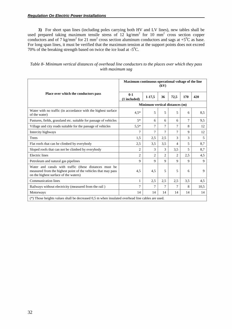
Regulation On Electric Power Installations
32
3) For short span lines (including poles carrying both HV and LV lines), new tables shall be
used prepared taking maximum tensile stress of 12 kg/mm2 for 10 mm
2 cross section copper
conductors and of 7 kg/mm2 for 21 mm
2 cross section aluminum conductors and sags at +5
0C as base.
For long span lines, it must be verified that the maximum tension at the support points does not exceed
70% of the breaking strength based on twice the ice load at -50C.
Table 8- Minimum vertical distances of overhead line conductors to the places over which they pass
with maximum sag
Place over which the conductors pass
Maximum continuous operational voltage of the line
(kV)
0-1
(1 included) 1-17,5 36 72,5 170 420
Minimum vertical distances (m)
Water with no traffic (in accordance with the highest surface of the water)
4,5* 5 5 5 6 8,5
Pastures, fields, grassland etc. suitable for passage of vehicles 5* 6 6 6 7 9,5
Village and city roads suitable for the passage of vehicles 5,5* 7 7 7 8 12
Intercity highways 7 7 7 7 9 12
Trees 1,5 2,5 2,5 3 3 5
Flat roofs that can be climbed by everybody 2,5 3,5 3,5 4 5 8,7
Sloped roofs that can not be climbed by everybody 2 3 3 3,5 5 8,7
Electric lines 2 2 2 2 2,5 4,5
Petroleum and natural gas pipelines 9 9 9 9 9 9
Water and canals with traffic (these distances must be
measured from the highest point of the vehicles that may pass
on the highest surface of the waters)
4,5 4,5 5 5 6 9
Communication lines 1 2,5 2,5 2,5 3,5 4,5
Railways without electricity (measured from the rail ) 7 7 7 7 8 10,5
Motorways 14 14 14 14 14 14
(*) Those heights values shall be decreased 0,5 m when insulated overhead line cables are used.

Regulation On Electric Power Installations
33
Table – 6 Minimum clearances (m) to installations around electrical power system installations
Type of
installati
on
With underearth cables With energy transmission lines
With
earthing
systems
Clearances
when being
side by side
or parallel
(m)
Clearances
for
Intersection
(m)
Clearances when being
side by side or parallel
(maximum oscillation
projection of the external
conductor and the pipe
axis)
Clearances
(to the pole foot)
for intersection
(m)
Clearances
to pole or
other
electrical
earthing
(m)
0 – 170 kV 0 – 170
kV
0 – 72 kV 72 – 420 kV 0 – 72 kV 72 – 420 kV 0 – 420 kV
(72 kV included) (72 kV included)
Natural
gas and petroleum
pipe line
(LNG,
LPG
included)
0,6* 0,4* 4 (10***) 10 (30***) 3 10 2**
* In necessary cases due to the regional and special conditions, these clearances may be reduced down to the
half of the clearances indicated above with some precautions to be taken. Insulated PVC or PE materials must be
placed between the underground cable and gas and petroleum pipeline. The dimensions of such materials must
be as follows, provided that the wall thickness is minimum 5 mm:
a) In case of intersection, a width of 2 times the gas or petroleum pipeline diameter and a length of twice the
intersection projections,
b) In case of parallel laying, a width of 2 times the petroleum or gas pipeline diameter and a length of normal
parallel clearance.
** If earthing of the electrical installations and the gas or petroleum pipe line installations or their earthings
intersect or if the clearance between them is less than 2 meters, then both sides of the earthing conductor must be
insulated for 2 meters from the intersection point on both sides on the gas or petroleum pipe, or such insulation
must be made so that the contact voltage of the pipeline will be less than 50 volts.
*** These are the minimum approach clearances to the accessible equipment of the pipeline sections such as
pressure step-up (pump – compressor), pressure step down and distribution stations etc. on the earth.
NOTE: The closest horizontal clearance of overhead line poles to railways and highways must be equal to the
greater of the following; either 2 meters higher than the full length of the pole over the earth in meters or out of
the expropriation border of the highway or railway. The clearance of GSM base station towers to the electrical
power system installations must be 2 meters higher than the length of the tower over the earth. Furthermore, the
provisions of “The Regulation on the Place of Installation of the Base Stations belonging to Mobile
Telecommunication Networks, their Measurements, Operation and Control” must be complied with.
b) The following assumptions must be made in order to calculate the tensile stress of the
conductors in long span lines and the maximum sag relating to such stresses:
1) Conductor is free of wind and ice at the following temperatures
In the 1st region -10
0C
In the 2nd
region -150C
In the 3rd
region -250C
In the 4th and 5
th regions -30
0C
2) The ice loads indicated in Table 9 act on the conductor at a temperature of -50C.

Regulation On Electric Power Installations
34
3) In the 1st region 50
0C
In the 2nd
region 450C
In the 3rd
, 4th and 5
th regions, 40
0C; it must be assumed that at those temperatures there
is no wind.
4) It must be assumed that wind blows on the conductors at -50C temperature in the horizontal
and even in the vertical direction. The wind force must be calculated as indicated in Article 48-b/1.
c) Special circumstances:
1) If the line passes through more than one region, the line section in each region must be
calculated with the values relating to that region.
2) If material and cross-section differences exist on the poles, the pole span must be
determined in accordance with the conductor giving the smallest one.
3) The calculation of the lines in the 1st region at an altitude of above 600 m must be made in
accordance with the conditions of the 2nd
region, the calculation of the lines in the 2nd
region at an
altitude of above 900 m must be made in accordance with the conditions in the 3rd
region and the
calculation of the lines in the 3rd
region at an altitude of above 1600 m must be made in accordance
with the conditions in the 4th region. In this case, 46-c/1 must be taken into consideration. On small
span low voltage lines, the land altitude differences must not be taken into account.
Poles
Article 47-a) Classification:
The poles must be classified as follows.
1) Support poles:
These are the poles, the duty of which is only to support the conductors, which are used only in
linear routes or at corners where conductors are connected with support tie.
2) Anchor poles:
These are the poles, the duty of which is to carry the line conductors and fix them with anchor
tie, that are used in the linear routes or at corners.
3) Termination poles:
These are the poles used at the beginning and end of the line.
4) Branch (distribution) poles:
These are the poles used at the lines where one or more lines branch.
Loads to be considered in pole calculations
Article 48-a) Vertical loads:
Vertical loads consist of the pole and traverse weights and insulator, conductor equipment and
the additional loads indicated below. For single-wire or braided conductors, k d kg/m ice load is
assumed. Here, d is the conductor diameter in (mm), (k) is a coefficient changing with regions. These
(k) coefficients are given in Table 9. It is assumed that there is no ice load on the poles and traverses.
Assembly load is taken as 100 kg at the points where the conductor is connected to the bracket
or traverse.
In dimensioning the members of the poles which make an angle up to 30 degrees with the
horizontal, it must be assumed that a 100 kg assembly load may act in the middle of these members
without considering any other load.
b) Horizontal Loads:
1) Wind Load:

Regulation On Electric Power Installations
35
i) In the calculation of the wind load acting on the phase and earth conductors, for wind spans up
to 200 m,
the equation W = c.p.d.aw (kg) must be used
and for the wind spans greater than 200 m
W= c.p.d.(80+0,6 aw) (kg) must be used.
Note: Unless the land conditions make it necessary, care must be taken not to have the pole
distances very much different from one another.
Where;
c: is the dynamic wind pressure coefficient depending on the shape, size and horizontal
characteristics of the member under the effect of wind (see Table 10)
p= v2 / 16: Dynamic wind pressure (kg/m
2) (see Table 11)
v: Wind speed (m/s),
aw: assumed wind clearance (m),
d: Braided or single-wire conductor diameter (m).
In the calculation of the string insulator oscillation angle, 70% of the wind load found herein
above must be assumed.
Table- 10 Dynamic wind pressure coefficients (c)
No Members under the effect of wind C
1 Single face cages made of profile steel 1,6
2 Square or rectangular section cage poles made of profile steel 2,8
3 Single face cages made of pipes 1,2
4 Square or rectangular section cage poles made of pipes 2,1
5 Circular – section wood, steel pipe and concrete poles 0,7
6 Hexagonal and octagonal sectioned steel pipes and concrete poles 1,0
7 Conductors up to a diameter of 12,5 mm 1,2
8 Conductors having a diameter between 12,5 and 15,8 mm 1,1
9 Conductors having a diameter more than 15,8 mm 1,0
ii) Towers with square or rectangular section, only one of the two parallel faces affected by the
wind must be taken into consideration.
For towers with square or rectangular section whose height to the top of the upper surface of the
traverse is greater than 60 m, it must be assumed that the wind comes under an angle of 450 with
respect to the line direction. This wind load can be calculated by separating the dynamic pressure to
the components parallel and perpendicular to the lateral faces of the pole. The projections of the
surfaces affected by these components on the vertical plane must be taken as the surface affected by
the wind.

Regulation On Electric Power Installations
36
Table- 11 Dynamic wind pressure (p)
Height over land (m) Dynamic wind pressure kg/m
2
Poles, traverses and insulators Conductors
0-15 55 44 (*)
15-40 70 53
40-100 90 68
100 – 150 115 86
150 – 200 125 95
(*) This value must be taken as 53 kg/m2 for long span lines.
2) Conductor tensile force:
The conductor tensile forces must be taken in accordance with various loading assumptions
given in article 49.
Loading assumptions for pole calculations
Article 49- In the calculation of each pole, each of the assumptions given hereunder for that
type of pole must be taken into consideration. For the poles that are under the effect of torsion moment
in normal operation condition due to the arrangement of the lines, that moment must also be taken into
consideration.
a) Support poles:
1) Normal support poles:
1st Assumption: The wind load and vertical loads without ice acting on the pole, insulators,
conductors and earth conductors in a direction perpendicular to the line direction.
2nd
Assumption: Wind load acting on the pole and the insulators in the direction of line and
single sided tensile force equal to 2% of the maximum tensile forces of the conductors and earth
conductors and vertical loads without ice.
3rd
Assumption: On overhead lines with string insulator, in case of breaking of a conductor (for
bundled conductors, all of the conductors forming the bundle) or an earthing conductor that will cause
the maximum stress, 1/3 of the maximum tensile force (1/5 in overhead lines with support insulator)
and vertical loads with ice.
For lines with more than six phase conductors, it must be assumed that the conductors of the two
phases are broken.
4th Assumption: (only for 380 kV and higher voltage overhead lines) On normal ice load relating
to each region, dynamic wind pressure of 20 kg/m2 to the conductors and the earthing conductor and
30 kg/m2 and vertical loads with ice to the insulators in perpendicular direction to the line direction.
In the application of this assumption, the surface of the pole under the effect of wind must be
increased by 50% due to ice.
5th Assumption: On the energy transmission lines of 380 kV and higher, provided that half of the
weight span is on one side of the pole and the other half on the other side, in ice conditions, the
difference force in the line direction when the condition of 100% of the normal ice weight on the
conductors and earth conductors on one side of the pole and 50% of the normal ice weight on the

Regulation On Electric Power Installations
37
conductors and earth conductors on the other side of the pole constitutes when the average span used
in the project is taken as basis and vertical loads with ice (insulator deviation must be considered).
2) Support poles at the corner:
1st Assumption: A force equal to the resultant of the maximum tensile forces of the conductors
and earth conductors, and vertical loads with ice.
2nd
Assumption: Wind load on the pole and the insulator in perpendicular to the bisector of the
line and single sided tensile force equal to 2% of the maximum tensile force of the earth conductors
and vertical loads without ice.
3rd
Assumption: Same as the third assumption of the normal support poles.
4th assumption: (only for 380 kV and higher voltage overhead lines) Over the normal ice load
relating to each region, 20 kg/m2 on the conductors and earth conductors in line with the bisector of
the line and in the resultant direction, with 30 kg/m2 dynamic wind pressure on the poles and
insulators and vertical loads with ice.
In the application of this assumption, the surface of the pole under the effect of the wind must be
increased by 50% due to ice.
5th Assumption: On 380 kV and higher voltage transmission lines, provided that half of the
weight span is on one side of the pole and the other half on the other side, loads perpendicular and
parallel to the bisector of the line formed by the condition of 100% of the normal ice weight on the
conductors and earth conductors on one side of the pole and 50% of the normal ice weight on the
conductors and earth conductors on the other side of the pole and vertical loads with ice.
6th Assumption: Resultant of tensile forces of the conductors and earth conductors at +5
0C and
the wind load acting on the pole, insulators, conductors and earth conductors in the direction of this
resultant (its bisector) and vertical loads without ice.
b) Anchor poles:
1) Normal anchor poles:
1st Assumption: The resultant force to be found by assuming that the maximum tensile forces of
the conductors is 100% on one side and assuming an attenuation in compliance with Table 12 on the
other side and vertical loads with ice.
2nd
Assumption: In case of breaking of one conductor in three-conductor lines and two
conductors in lines with more than three conductors so as to create maximum stress on the pole, 75%
of the maximum tensile force and vertical loads with ice. When bundled conductors are used, a bundle
must be assumed to be a single conductor.
3rd
Assumption: In case of breaking of a earth conductor so as to create maximum stress on the
pole, 75% of the maximum tensile force and vertical loads with ice.
4th Assumption: Wind load acting on the pole, insulators, conductors and earth conductors in a
direction perpendicular to the line direction and all vertical loads without ice.
Table 12 –Tensile force attenuation percentages to be used in pole calculations
Total number of conductors (except the earth
conductor)
Single-sided attenuation
percentages %
2 100
3 75
4 60

Regulation On Electric Power Installations
38
5 50
6 and more 40
5th Assumption: (only 380 kV and for higher voltage overhead lines) On the ice load relating to
each region, the dynamic wind pressure of 20 kg/m2 in a direction perpendicular to the line direction
on the conductors and earth conductors, and of 30 kg /m2 on the poles and insulators and vertical loads
with ice.
In the application of this assumption, the surface of the pole under the effect of the wind must be
increased by 50% due to ice.
2) Anchor poles at the corner
1st Assumption: The resultant force to be found by assuming that the maximum tensile forces of
the conductors is 100% on one side and assuming attenuation compliant with Table 12 on the other
side and vertical loads with ice.
2nd
Assumption: In case of breaking of one conductor in three-conductor lines and two
conductors on the same side in lines with more than three conductors so as to create maximum stress
on the pole, 75% of the maximum tensile force and vertical loads with ice. When bundled conductors
are used, a bundle must be assumed to be a single conductor.
3rd
Assumption: In case of breaking of an earthing conductor so as to create maximum stress on
the pole, 75% of the highest tensile force and vertical loads with ice.
4th Assumption: The resultant of the tensile forces of the conductors and earth conductors under
wind conditions at +50C and the wind load acting on the pole, insulators, conductors and earth
conductors in the direction of this resultant (bisector).
5th Assumption: A force equal to the resultant of the highest tensile forces of the conductors and
earth conductors and vertical loads with ice.
6th Assumption: (only for 380 kV and higher voltage overhead lines) Assuming that a wind of 20
kg/m2 blows over the normal ice load relating to each region at -5
0C, the resultant of the tensile forces
of the conductors and earth conductors and a wind pressure of 20 kg/m2 on the conductors and earth
conductors with ice and 30 kg/m2 on the insulators in the direction of this resultant (bisector) and
vertical loads with ice.
In the application of this assumption, the surface of the pole under the effect of the wind must be
increased by 50% due to ice.
c) Termination poles:
1st Assumption: A single sided load equal to the maximum tensile forces of the conductors and
earth conductors and vertical loads with ice. Furthermore, in case there is a torsion moment in
accordance with the way of fixing the conductors, this moment.
2nd
Assumption: In case of breaking of one conductor in three-conductor lines and two
conductors on the same side in lines with more than three conductors so as to create maximum stress
on the pole, 100% of the maximum tensile force and vertical loads with ice. (When bundled
conductors are used, a bundle must be assumed to be a single conductor.)
3rd
Assumption: In case of breaking of an earthing conductor so as to create maximum stress on
the pole, 100% of the highest tensile force and vertical loads with ice.
4th Assumption: Wind load acting on the pole, insulators, conductors and earth conductors in
perpendicular direction to the line direction and tensile forces in the line direction in wind condition
and vertical loads.
5th Assumption: (only for 380 kV and higher voltage overhead lines) Over the normal ice load
relating to each region, 20 kg/m2 dynamic wind pressure on the conductors and earth conductors in

Regulation On Electric Power Installations
39
perpendicular direction to the line direction and 30 kg/m2 on the insulators in the line direction and
strain forces in line direction in this condition.
In the application of this assumption, the surface of the pole under the effect of the wind must be
taken increased by 50% due to ice.
On lines with voltages lower than 380 kV, depending on the condition of the land and the
meteorological conditions, the assumption that wind blows on ice may be applied by justified
application to the Ministry of Energy and Natural Resources or the relevant organizations authorized
by the Ministry.
d) Branch poles:
1st Assumption: A load equal to the resultant of the maximum tensile forces of the conductors
and earth conductors on the main line and the branches and vertical loads with ice.
2nd
Assumption: The resultant load to be found by taking into account attenuation in compliance
with Table 12 on the main line or on one of the branches so as to give the maximum resultant stress
and vertical loads with ice.
On long span lines, maximum 20 m branches may be separated with loosely drawn conductors
from the poles connected with support ties. Otherwise, the main line must be connected with anchor
tie. In this case, attenuation must be considered on the main lines.
3rd
Assumption: The resultant of the tensile forces with wind of the conductors and earth
conductors on the main line and the branches at +50C and the main line load in the direction of this
resultant, and vertical loads without ice.
4th Assumption: On long span lines, in case of breaking of a conductor so as to create maximum
stress, by taking each conductor separately, maximum tensile force and vertical loads with ice.
General Provisions relating to the pole assumptions
Article 50- a) Bending moments, if any, that may occur due to the vertical weights must be
calculated for each loading condition given in the assumptions relating to the pole.
b) Earth conductor towers, traverses and brackets must be checked for lifting up, if any, and for
turning moments that may occur on both sides of the pole due to different weight spans.
c) For poles with square or rectangular shaped sections having a height more than 60 m up to the
upper surface of the top traverse, in addition to the pole loading assumptions indicated above, the wind
must be assumed to come under an angle of 450 to the pole, conductors, earth conductors and
insulators in accordance with the line direction.
d) Only for the anchor and termination poles, the calculation of the earth conductor towers,
traverses, brackets and insulator irons must be performed taking into account the greatest loads in the
pole loading assumptions.
e) In the pole calculations to be performed for the first region, separate wind loads must not be
considered for the following assumptions:
- 3rd
Assumption related with the support poles,
- 1st, 2
nd and 3
rd Assumptions for the anchor poles
- 1st and 2
nd Assumptions related with the anchor poles at the corner,
- 2nd
and 3rd
Assumptions related with the termination poles
- 2nd
and 4th Assumptions related with the branch poles.
f) It must be taken into consideration that the highest conductor tension in the First Region may
occur at +50C and in windy condition or at the minimum temperature.
Steel poles

Regulation On Electric Power Installations
40
Article 51- Dimensioning the pole members and maximum tensions assumed for the pole
components:
The safety coefficient of all members of the steel poles that are under pressure, tensile or
bending stress with respect to flow tension must not be less than 1,5.
a) For various tensions in the calculation of the steel poles, the cross-sections given in Table 13
must be used.
In dimensioning the pole members (prepared in accordance with a safety coefficient of 1,5), the
values given in Table 14 must be taken as basis.
Types of steel other than the ones indicated in Table 14 may be used only if they comply with
the quality regulation and construction standards applicable for them and if the values relating to these
materials are equivalent to the values of St 37 as a minimum.
b) The tensile and bending tension accepted for another type of steel permitted for use, may be
found by multiplying the tension given in the first row of Table 13 for St 37 with σF/2400 kg/cm2 or by
dividing the flow tension by the safety coefficient. Here, σF is the minimum flow limit of the steel in
kg/m2 as guaranteed in the quality regulation.
c) The bars of the steel towers under pressure and therefore forced to twist must be dimensioned
as indicated below in terms of torsion strength:
σem = S. ω / F
Here;
S: Bar pressure force
ω: Torsion coefficient,
F: Cross-section of the solid member (not attenuated cross-section of the member)
σem: Pressure safety tension. This value is 1600 kg/cm2 for St 37 and 2400 kg/cm
2 for St 52 for
1,5 safety.
Torsion coefficients (λ) prepared for various slenderness values (ω) of bars made of St 37 and St
52 steel are given in Table 16 and Table 17.
1) Material thickness of the angles that will be used in dimensioning the steel cage poles must
be minimum 5 mm for poles and 4 mm for other load-bearing members and 3 mm for zero members
and must not be less than the following.
- For zero members, L 35x35x3 (TS 908/1 – FE37)
- For load bearing members (other than struts) 40x40x4
- For poles L 50x50x5 (TS 908/1 – FE37)
If the distance between the point where the internal radius of curvature of the angle ends and the
edge of the section is (b) and the angle thickness is (t), then b/t ratio must not exceed 16.
2) Upper limits of slenderness values:
i) For struts and main pressure members (bracket and pole): 120
ii) Other pressure members (cross and similar): 200
iii) For zero members (members not bearing load according to calculation): 250
iv) For bracket members subject to weight only: 300
v) For other members subject to weight only: 500
3) For type A poles, the torsion length must be taken as 65% of the length of the pole over the
earth.
4) Other methods to be applied for the calculation of pressure members:
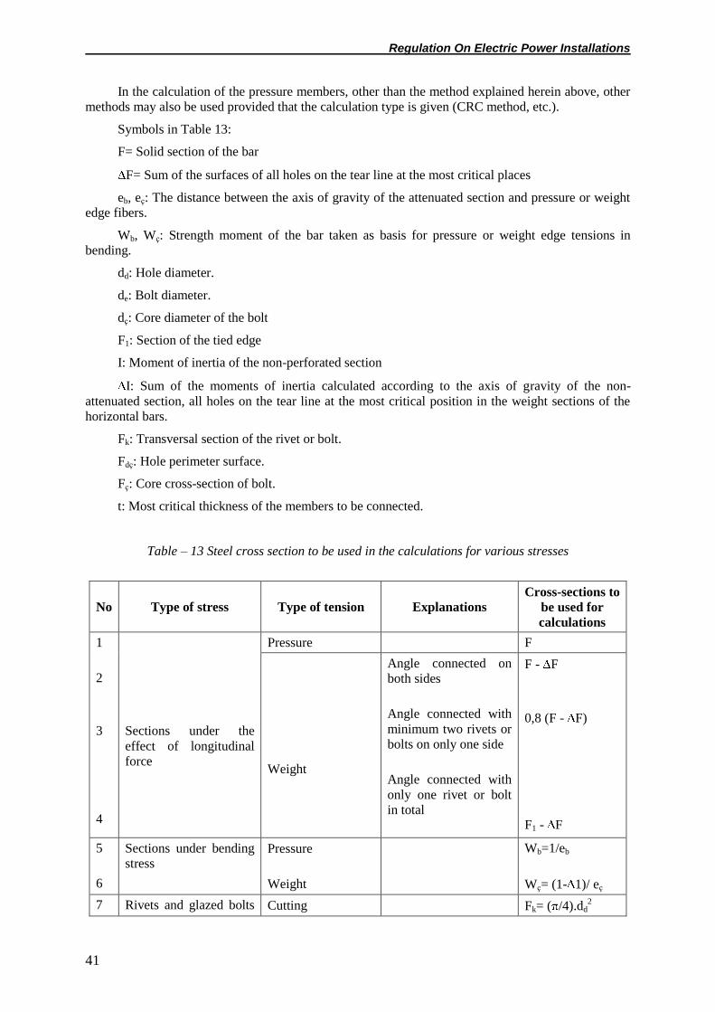
Regulation On Electric Power Installations
41
In the calculation of the pressure members, other than the method explained herein above, other
methods may also be used provided that the calculation type is given (CRC method, etc.).
Symbols in Table 13:
F= Solid section of the bar
F= Sum of the surfaces of all holes on the tear line at the most critical places
eb, eç: The distance between the axis of gravity of the attenuated section and pressure or weight
edge fibers.
Wb, Wç: Strength moment of the bar taken as basis for pressure or weight edge tensions in
bending.
dd: Hole diameter.
de: Bolt diameter.
dç: Core diameter of the bolt
F1: Section of the tied edge
I: Moment of inertia of the non-perforated section
I: Sum of the moments of inertia calculated according to the axis of gravity of the non-
attenuated section, all holes on the tear line at the most critical position in the weight sections of the
horizontal bars.
Fk: Transversal section of the rivet or bolt.
Fdç: Hole perimeter surface.
Fç: Core cross-section of bolt.
t: Most critical thickness of the members to be connected.
Table – 13 Steel cross section to be used in the calculations for various stresses
No Type of stress Type of tension Explanations
Cross-sections to
be used for
calculations
1
2
3
4
Sections under the
effect of longitudinal
force
Pressure F
Weight
Angle connected on
both sides
Angle connected with
minimum two rivets or
bolts on only one side
Angle connected with
only one rivet or bolt
in total
F - F
0,8 (F - F)
F1 - F
5
6
Sections under bending
stress Pressure
Weight
Wb=1/eb
Wç= (1- 1)/ eç
7 Rivets and glazed bolts Cutting Fk= ( /4).dd2
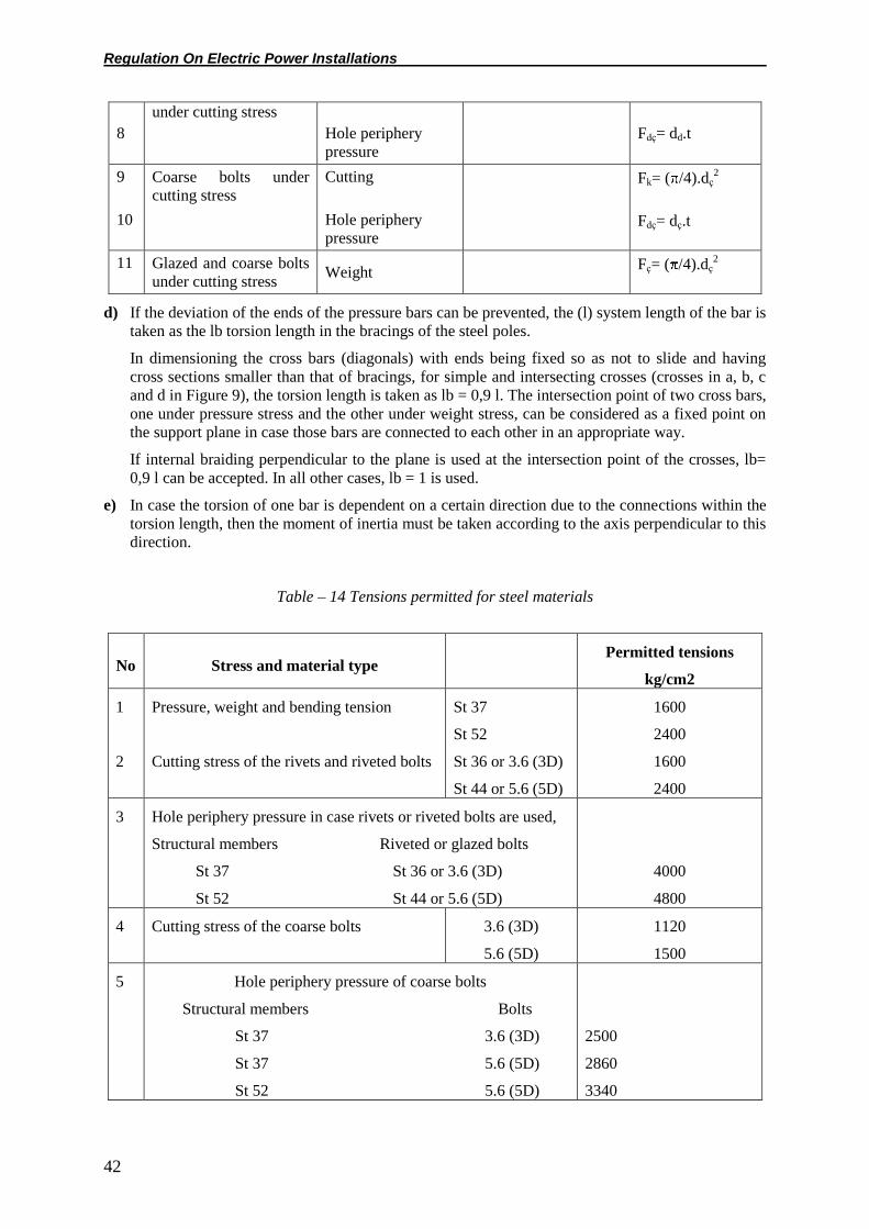
Regulation On Electric Power Installations
42
8
under cutting stress
Hole periphery
pressure
Fdç= dd.t
9
10
Coarse bolts under
cutting stress
Cutting
Hole periphery
pressure
Fk= ( /4).dç2
Fdç= dç.t
11 Glazed and coarse bolts
under cutting stress Weight
Fç= ( /4).dç2
d) If the deviation of the ends of the pressure bars can be prevented, the (l) system length of the bar is
taken as the lb torsion length in the bracings of the steel poles.
In dimensioning the cross bars (diagonals) with ends being fixed so as not to slide and having
cross sections smaller than that of bracings, for simple and intersecting crosses (crosses in a, b, c
and d in Figure 9), the torsion length is taken as lb = 0,9 l. The intersection point of two cross bars,
one under pressure stress and the other under weight stress, can be considered as a fixed point on
the support plane in case those bars are connected to each other in an appropriate way.
If internal braiding perpendicular to the plane is used at the intersection point of the crosses, lb=
0,9 l can be accepted. In all other cases, lb = 1 is used.
e) In case the torsion of one bar is dependent on a certain direction due to the connections within the
torsion length, then the moment of inertia must be taken according to the axis perpendicular to this
direction.
Table – 14 Tensions permitted for steel materials
No Stress and material type Permitted tensions
kg/cm2
1
2
Pressure, weight and bending tension
Cutting stress of the rivets and riveted bolts
St 37
St 52
St 36 or 3.6 (3D)
St 44 or 5.6 (5D)
1600
2400
1600
2400
3 Hole periphery pressure in case rivets or riveted bolts are used,
Structural members Riveted or glazed bolts
St 37 St 36 or 3.6 (3D)
St 52 St 44 or 5.6 (5D)
4000
4800
4 Cutting stress of the coarse bolts 3.6 (3D)
5.6 (5D)
1120
1500
5 Hole periphery pressure of coarse bolts
Structural members Bolts
St 37 3.6 (3D)
St 37 5.6 (5D)
St 52 5.6 (5D)
2500
2860
3340

Regulation On Electric Power Installations
43
6 Weight stress of the coarse bolts and riveted
bolts
3.6 (3D)
5.6 (5D)
1120
1500
Note: 3.6 (3D) and 5.6 (5D) are the old and new quality signs of the rivet or bolt materials
indicated in DIN norm no 267.
If the struts are made of equal edge angles in a steel pole and if the crosses are arranged as
shown in Figure 9 a and b, Ix moment of inertia is used in the calculation of the struts. For calculations
where the crosses are arranged as in c and d in Figure 9, the minimum moment of inertia, In, is used.
Figure 9 – Open view of steel pole
Bolts
Article 52- Minimum distances that must be provided on the ends of the angles, at their edges
and between the bolt centers in accordance with the diameters of the bolts under mechanical stress
force are shown in Table 15.
The holes in angles and plates used in steel poles must be opened so as not to cause any tears,
cracks, crushes and burrs that decrease the strength of the materials and can be seen with naked eye.
Opening the holes with a punch on the members under continuous tensile stress on steel poles’
brackets and traverses is not permitted.
Bolts having diameters less than 12 mm must not be used on steel poles and the necessary
precautions must be taken to prevent loosening of the nuts.
Table 15 – Minimum distances of the bolt hole centers to the ends, edges and one another
Bolt diameter (mm) 12 14 16 20 22 24 27 30
Distance of the hole center to the
end in the direction of force (mm) 20 23 25 30 35 40 45 50
Distance of hole centers to the
edge at the joints and traverse
weight members (mm)
25 30 35 40 45 50 55 65
Distance of the hole center to the
edge in a direction perpendicular
to the force direction (mm)
16 18 20 25 27 30 34 38
Distance between the bolt centers
(mm) 35 40 44 54 59 64 70 80
Minimum angle edge (mm) 35 40 45 60 65 70 75 80
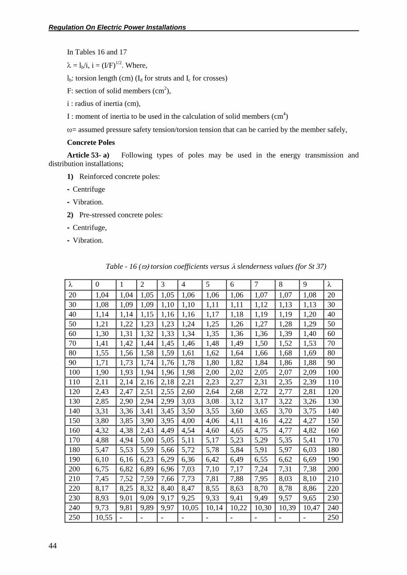
Regulation On Electric Power Installations
44
In Tables 16 and 17
= lb/i, i = (I/F)1/2
. Where,
lb: torsion length (cm) (Id for struts and Ic for crosses)
F: section of solid members (cm2),
i : radius of inertia (cm),
I : moment of inertia to be used in the calculation of solid members (cm4)
= assumed pressure safety tension/torsion tension that can be carried by the member safely,
Concrete Poles
Article 53- a) Following types of poles may be used in the energy transmission and
distribution installations;
1) Reinforced concrete poles:
- Centrifuge
- Vibration.
2) Pre-stressed concrete poles:
- Centrifuge,
- Vibration.
Table - 16 ( torsion coefficients versus slenderness values (for St 37)
λ 0 1 2 3 4 5 6 7 8 9 λ
20 1,04 1,04 1,05 1,05 1,06 1,06 1,06 1,07 1,07 1,08 20
30 1,08 1,09 1,09 1,10 1,10 1,11 1,11 1,12 1,13 1,13 30
40 1,14 1,14 1,15 1,16 1,16 1,17 1,18 1,19 1,19 1,20 40
50 1,21 1,22 1,23 1,23 1,24 1,25 1,26 1,27 1,28 1,29 50
60 1,30 1,31 1,32 1,33 1,34 1,35 1,36 1,36 1,39 1,40 60
70 1,41 1,42 1,44 1,45 1,46 1,48 1,49 1,50 1,52 1,53 70
80 1,55 1,56 1,58 1,59 1,61 1,62 1,64 1,66 1,68 1,69 80
90 1,71 1,73 1,74 1,76 1,78 1,80 1,82 1,84 1,86 1,88 90
100 1,90 1,93 1,94 1,96 1,98 2,00 2,02 2,05 2,07 2,09 100
110 2,11 2,14 2,16 2,18 2,21 2,23 2,27 2,31 2,35 2,39 110
120 2,43 2,47 2,51 2,55 2,60 2,64 2,68 2,72 2,77 2,81 120
130 2,85 2,90 2,94 2,99 3,03 3,08 3,12 3,17 3,22 3,26 130
140 3,31 3,36 3,41 3,45 3,50 3,55 3,60 3,65 3,70 3,75 140
150 3,80 3,85 3,90 3,95 4,00 4,06 4,11 4,16 4,22 4,27 150
160 4,32 4,38 2,43 4,49 4,54 4,60 4,65 4,75 4,77 4,82 160
170 4,88 4,94 5,00 5,05 5,11 5,17 5,23 5,29 5,35 5,41 170
180 5,47 5,53 5,59 5,66 5,72 5,78 5,84 5,91 5,97 6,03 180
190 6,10 6,16 6,23 6,29 6,36 6,42 6,49 6,55 6,62 6,69 190
200 6,75 6,82 6,89 6,96 7,03 7,10 7,17 7,24 7,31 7,38 200
210 7,45 7,52 7,59 7,66 7,73 7,81 7,88 7,95 8,03 8,10 210
220 8,17 8,25 8,32 8,40 8,47 8,55 8,63 8,70 8,78 8,86 220
230 8,93 9,01 9,09 9,17 9,25 9,33 9,41 9,49 9,57 9,65 230
240 9,73 9,81 9,89 9,97 10,05 10,14 10,22 10,30 10,39 10,47 240
250 10,55 - - - - - - - - - 250

Regulation On Electric Power Installations
45
b) In the calculation of the concrete poles, the safety coefficient must not be less than 1,5 with
respect to flow tension of the steel and the breaking safety coefficient must not be less than 2 in
breaking test.
In the calculation and construction of the concrete poles and traverses, the current Turkish
Standards must be applied. If there are issues not covered in those Standards, the relevant international
standards must be complied with. In that case, the employer must indicate in the technical
specifications the standard to be complied with.
Note: The safety coefficients of the composite poles must be same as the concrete poles.
Wooden Poles
Article 54-a) All the entire body of the wooden poles to be used for a period of more than three
years must be protected against decaying effectively (impregnation etc.).
b) Top of the wooden poles must be protected effectively against the decaying effect of rain.
For double and A type poles, the connections must be made so as to prevent the accumulation of rain.
c) The stresses given for wooden pole materials are shown in Table 18.
d) For A Type poles, at the center of the torsion length, the moment of inertia must be
minimum:
I = n.5.P.l2 (cm4).
Only for hard wood, I = n.3.P.l2 (cm
4) can be accepted. Where;
P: Pressure force (tons), l: Torsion length (m)
n: torsion safety coefficient and n = 4.
Table – 17 ( torsion coefficients versus slenderness values (for St 52).
λ 0 1 2 3 4 5 6 7 8 9 λ
20 1,06 1,06 1,07 1,07 1,08 1,08 1,09 1,09 1,10 1,11 20
30 1,11 1,12 1,12 1,13 1,14 1,15 1,15 1,16 1,17 1,18 30
40 1,19 1,19 1,20 1,21 1,22 1,23 1,24 1,25 1,26 1,27 40
50 1,28 1,30 1,31 1,32 1,33 1,35 1,36 1,37 1,39 1,40 50
60 1,41 1,43 1,44 1,46 1,48 1,49 1,51 1,53 1,54 1,56 60
70 1,58 1,60 1,62 1,64 1,66 1,68 1,70 1,72 1,74 1,77 70
80 1,79 1,81 1,83 1,86 1,88 1,91 1,93 1,95 1,98 2,01 80
90 2,05 2,10 2,14 2,19 2,24 2,29 2,33 2,38 2,43 2,48 90
100 2,53 2,58 2,64 2,69 2,74 2,79 2,85 2,90 2,95 3,01 100
110 3,06 3,12 3,18 3,23 3,29 3,35 3,41 3,47 3,53 3,59 110
120 3,65 3,71 3,77 3,83 3,89 3,96 4,02 4,09 4,15 4,22 120
130 4,28 4,35 4,45 4,48 4,55 4,62 4,69 4,75 4,82 4,89 130
140 4,96 5,04 5,11 5,18 5,25 5,33 5,40 5,47 5,55 5,62 140
150 5,70 5,78 5,86 5,93 6,01 6,09 6,16 6,24 6,32 6,40 150
160 6,48 6,57 6,65 6,73 6,81 6,90 6,98 7,06 7,15 7,23 160
170 7,32 7,41 7,49 7,58 7,67 7,76 7,85 7,94 8,03 8,12 170
180 8,21 8,30 8,39 8,48 8,58 8,67 8,76 8,86 8,95 9,05 180
190 9,14 9,24 9,34 9,44 9,53 9,63 9,73 9,83 9,93 10,03 190
200 10,13 10,23 10,34 10,44 10,54 10,65 10,75 10,85 10,96 11,06 200
210 11,17 11,28 11,38 11,49 11,60 11,71 11,82 11,93 12,04 12,15 210

Regulation On Electric Power Installations
46
220 12,26 12,37 12,48 12,60 12,71 12,82 12,94 13,05 13,17 13,28 220
230 13,40 13,52 13,63 13,75 13,87 13,99 14,11 14,28 14,35 14,47 230
240 14,59 14,71 14,83 14,96 15,08 15,20 15,33 15,45 15,58 15,71 240
250 15,83 - - - - - - - - - 250
Table – 18 Stresses permitted for wooden materials
Type of wood Bending stress
kg/cm2
Weight stress
kg/cm2
Pressure stress
kg/cm2
Cutting stress
kg/cm2
Pines
1. In fiber direction
2. In direction
perpendicular to fiber
145
-
145
-
110
35
18
30
Hard woods
1. In fiber direction
2. In direction
perpendicular to fiber
190
-
190
-
120
50
20
40
Note: Here, the breaking strength is assumed to be 500 kg/cm2 for pines and 800 kg/cm
2 for hard
wood. When poles other than pines and hard wood are desired to be used, the safety coefficient for
weight stress must be 4.
The torsion length for the poles buried in soil is the distance from the wedge or stud in the
middle of the pole to the half of the burying depth.
e) Double poles must be tied to each other in an appropriate way. Double poles to be connected
to each other with a wedge must be equipped with minimum 4-6 wedges along their length and must
be screwed with bolts.
f) No wooden poles must be used in the forest areas unless absolutely necessary.
Pole guy wires
Article 55-a) Hot galvanized steel ropes not containing any fiber sections must be used as the
guy wire.
b) Theoretical breaking safety of the steel guy wire must not be less than 2,5. However,
regardless of the result of the calculation, the cross-section of the guy wire on the earth must not be
less than 25 mm2 and the cross-section of the part in the earth must not be less than 50 mm
2. The part
entering the earth may be made of round steel with minimum 10 mm diameter.
c) For guy wire connection parts, effective breaking or sliding load may not be less than 2,25
times the maximum load that will act on the guy wire.
d) Guy wire ropes must be equipped with devices that will ensure re- tensioning. These devices
must be at a height that can be reached from the earth.
e) Connection parts must be secured against loosening.
f) Guy wires must be used at locations where they will not be damaged and will not hinder the
traffic.
g) Guy wires must be insulated with insulators that have a minimum dry arc voltage equal to
twice the nominal phase-to-phase voltage of the conductors on the poles they are connected to and a
minimum wet arc voltage equal to such nominal voltage. Mechanical strength of the insulators must be

Regulation On Electric Power Installations
47
as much as the strength of the guy wire as a minimum. The place where the insulator is fixed must be
away from the horizontal projection of the conductors passing over it. The height of the insulator from
the earth must be minimum 2,40 m.
Guy wires may not be insulated if they are connected at least 50 cm below the lowest conductors
of the low voltage lines with earthed or wooden poles.
Foundations
Article 56-a) Dimensioning of foundations:
Poles must be calculated according to the heaviest conditions in the loading assumptions
indicated in Article 49 regarding safety against falling down. In the foundation calculations, a safety
must be provided that is higher than the safety values foundation used for pole design. In the
calculation of pole foundations, the values in Table 19 must be used for various soils.
b) Protection of the parts of the poles inside the foundation:
1) Necessary precautions against corrosion and decaying must be taken in steel poles in order to
protect the parts remaining inside the earth. For steel poles with concrete foundation, no precautions
are necessary for the protection of the parts inside the concrete.
2) The part of the wooden poles that will remain in soil must have the following minimum
lengths. For poles up to a height of 8 m from the earth, 130 cm; for each meter over 8 meters, 10 cm
must be added to this length. Wooden poles must be fixed with stones surrounding them, taking into
account the local conditions.
Table – 19 Soil characteristics to be used in the calculation of pole foundations
Type of soil
Soil safety tension
at 1,5 m depth
kg/cm2
Soil density
kg/m3
Internal friction
angle
Degrees
Soil slope angle
Degrees
Filled soil, naturally
wet 0,6 1600 32 30
Soil that is not sticky:
fine and medium size
sand
1 1800 30 30
Coarse sand, particle
soil (1-3mm) - 1900 34 28
Sand with 1/3 gravel 1,6 1800 30 30
Round gravel 2 1900 30 30
Sharp edged ballast 2 1800 36 27
Sticky soil, mud, clay 1 2000 25 32
Necessary precautions must be taken in order to prevent the decay of the part of the wooden
poles remaining in the foundation and the part of approximately 30 cm above the earth due to the
effect of the water in the soil. These precautions must be so as to ensure the strength of the upper side
of the pole as a minimum in the mentioned parts. The wooden poles may not be directly embedded in
concrete.
3) For the values given in Table 19 to be valid, it is assumed that the foundation pits are
perfectly filled and compacted.

Regulation On Electric Power Installations
48
4) In case water is encountered in the foundation, the weakening in the bearing strength of the
foundation must be considered taking the worst foundation water level into account.
5) In the foundation calculations, the density of the concrete without iron must be maximum
2200 kg/m3 and the density of the concrete with iron must be taken as 2400 kg/m
3.
Earthing of overhead lines
Article 57- The provisions of the Electrical Installations Earthing Regulation must be applied in
earthing the overhead lines.
If the poles are earthed one by one on the high voltage overhead lines, in case the earth
resistance indicated in this regulation can not be obtained, necessary precautions for the earth
resistance to be at this value must be taken.
Cables
Article 58- For installations within the scope of this regulation, cables compliant with Turkish
Standards must be used. When those can not be found, cables compliant with standards indicated in
Article 1 must be used.
a) Cable selection:
In addition to other conditions that must be complied with in cable selection, the following must
also be considered:
1. Nominal voltage:
Two nominal voltage values are used for the cables:
U: Phase-to-phase voltage,
U0: Voltage between the conductor and the metal shield or earth.
2. Load current:
Depending on the load current, cable cross-sections must be determined in accordance with
various cable types, flooring conditions and environmental conditions or the loading conditions
indicated by the manufacturers.
Some of the conditions to be taken into consideration in the determination of the cable cross-
section are given hereunder:
- Future load increases
- Permitted conductor temperature (conductor temperature in continuous use must not be
greater than the indicated values for the chosen cable type).
- Environmental conditions that are effective in dissipating the heat created in the cable
(thermal resistance of the soil, etc.).
- Whether the cable is single-core or multi-core
- Whether the cable is laid overhead or underground
- Method used for laying the cable
- Specific thermal resistance
In the performance of these calculations, the tables related with the cables included in the
relevant standards must be used.
3. Short circuit strength
The cables must withstand the short circuit currents that may occur in the networks where they
are used. The short circuit strength of the cables must be shown with calculation. The cable conductor
temperature as the result of the short circuit must be maximum 1600C for PVC isolated cables and
2500C for XLPE isolated cables.

Regulation On Electric Power Installations
49
Especially for the single-core cables, the cable fixing parts must be chosen in dimensions that
will bear the forces to be caused by the short circuit and a sufficient distance must be provided
between them.
4. Voltage drop:
While calculating the voltage drop of the cables, inductive impedance as well as the ohmic
resistance must be taken into account.
The voltage drop must not exceed 7% in high voltage distribution networks starting from the
secondary of the step-down transformer substations. But for ring networks, for supplying the ring
unilaterally in cases of failure, the voltage drop examinations must be performed. In this case, voltage
drop must not exceed 10%.
The voltage drop in low voltage installations must not exceed 5%. For installations having their
own transformers, the total voltage drop from the most critical point starting from the LV output of the
transformers to the consumer must not exceed 6,5% for illumination loads and 8% for motor loads. In
case of ring, the explanations given above must apply without change for high voltage.
5. Effective power loss:
Cable cross-section must be chosen according to the maximum cross-section that will be
calculated in accordance with the methods indicated in Article 58 – a/2, 3 and 4. However, cables with
larger cross-sections (economic section) may be used, taking the line losses into account. On important
cable lines, economic calculation must be performed taking into account the cable cost, line losses,
annual use period, energy price, real interest, depreciation period. In this case, the use of economic
section is recommended.
6. Dielectric loss:
Especially when high voltage and long cables are used, cables with low dielectric losses (such as
XLPE) must be chosen, except in special conditions.
7. Mechanical conditions:
Cable must be chosen taking into account the mechanical conditions at the place of use. At
locations where mechanical stress exists, cable types that are strong against this must be chosen. For
example, cables under weight stress must be shielded and they must be fixed with clamps bearing the
weight stress at the sloped locations and near the joint boxes.
For cables directly buried in the earth, steel sheath are recommended. It is recommended to use
cables without steel sheath underground in concrete channels, concrete pipes or PVC pipes taken into
concrete enclosures.
8. Chemical effects and external effects:
Cables must be chosen of a type to withstand chemical effects, water, humidity and air
conditions and other environmental effects at the locations where they are laid.
9. Cables must be chosen of a type appropriate for the operational conditions.
10. Location:
Cables must be chosen appropriately for the characteristics of the locations where they will be
laid. In all structures such as high-storey buildings, hospitals, tunnels, theaters, schools, shopping
centers etc. where people are present in large numbers and where panic may occur, halogen-free
cables that emit small amount of smoke must be used.
b) Laying the cables:
1. Locations, where the underground cables are laid must be as far as possible from the
mechanical, chemical and thermal effects or must be protected against them.

Regulation On Electric Power Installations
50
2. In order to protect the cable and its surrounding against the danger of fire and in order to
prevent the spread of fire, cables must not be laid on flammable materials. The jute layers of the cables
must be peeled off, if any.
3. At building entrances, cables must be taken in pipes and the space between the cable and the
pipe must be filled with plastic silicon or similar material. For this purpose, cement will not be used.
Steel pipes must be used where mechanical shocks may occur. Wherever the steel pipes are used, the
three phases must be passed through the same pipe. In case of single-core, antimagnetic material must
be used.
4. HV cables must be equipped with cable glands indoor and outdoor. The cable glands must
be so as to prevent the entrance of water, humidity inside the cable. If precautions are taken to prevent
the ingress of water in LV cables, it is possible not to use the cable glands.
5. Cable joints must be made always with their special joint accessories or within joint boxes.
Joints must be mechanically reliable, the leakage of water and humidity inside them must be prevented
and a good electrical conductivity must be provided. Joints must be chosen of a type appropriate for
the place of installation.
6. Protective shields or insulators of the cables must not under stress at the locations where
they exist and must not be damaged. Cables must be taken in protective concrete pipes or pipes
whenever necessary.
7. Members used in fixing the single core cables must not form magnetic rings.
8. For the supply arrangements consisting of single-core systems, in single row placement
order, the cores must be in the following arrangement:
L1 L2 L3 L3 L2 L1 L1 L2 L3 L3 L2 L1
and for multi-layer placements, there must be a distance of minimum 20 cm between the layers
and the arrangement must be as follows:
1st layer 2
nd layer
L1 L2L3 L3 L2 L1
L1 L2 L3 L3 L2 L1
L1 L2 L3 L3 L2 L1
In these supply arrangements, the same phase must never be installed side by side; in other
words, the arrangement must not be as L1L1L1, L2L2L2, L3L3L3. There must be a minimum
distance of one cable diameter between the systems. Furthermore, the length of all systems must be
approximately equal.
9. Minimum bending radius of the cables must be as given in Table 20, D being the external
diameter of the cable.
Table 20 – Minimum bending radius in cables
Number of cores of the cable Cable Bending Radius (R)
XLPE and PVC
Insulated LV
XLPE and PVC
Insulated HV Armored Cables
Three-core 12 x D 15 x D 15 x D
Single-core 15 x D 15 x D 15 x D

Regulation On Electric Power Installations
51
10. During laying, all conductors must be brought together and tied to each other with pulling
clips for laying the cable. The highest laying tension must be 5 kg/mm2 for copper conductors and
3kg/mm2 for aluminum conductors.
11. Cables to be laid underground must be buried at a minimum depth of 80 cm in the streets
and avenues. This depth must be minimum 60 cm at other locations. This depth may be decreased by
20 cm taking special protective precautions in necessary cases.
12. Cables laid outdoors must be protected from the effects of sun ray as much as possible.
13. Cables, depending on relevant conditions must be laid underground, on perforated trays or
ladder shelves fixed on the cable ducts or the walls. It is not recommended to lay the cables using trays
without perforation. Approximately 10 cm thick sieved sand layer must be provided under and over it
for the cables laid underground. On the sand laid on the cable, and between the HV and LV cables laid
in the same duct, protective components made of solid brick or minimum 6 cm thick concrete plate or
plastic material must be placed. This way, the cable must be protected against the shocks caused by
the workers opening the pit and it must be understood beforehand that there is a cable at that location.
Polyethylene warning band of minimum 10 cm wide must be placed approximately 30 cm above that
protector.
14. The minimum distance between an energy cable and another one or a control cable must be
as much as the cable diameter but not less than 7cm. No distance is necessary between the control
cables.
15. In case an energy cable and telecommunication, railway, highway etc. – related cables
approach to or intersect each other, the distance between them must be minimum 30 cm. If this
distance is smaller, the cables must be protected with plates, half-concrete pipes or pipes made of non-
flammable materials.
16. Cables to be passed under railways, water canals and the roads carrying vehicle traffic must
be laid within HDPE or PVC pipes with concrete enclosure or concrete cable channels. Upper edges of
those pipes and ducts must be minimum 1 m below the lower sides of the rails and the surface of the
road.
c) Protection of cables:
Cables may be protected against over voltages with lightning arresters that will be placed at their
opposite ends.
d) Earthing the cables:
The provisions of Electrical Installations Earthing Regulation must be applied.
e) Marking the cable routes:
Organizations having cable installations must exactly mark their locations and must submit the
plans showing the passage routes of these cables to the relevant municipalities within municipal
borders and surrounding regions, and to the relevant property administration directorates at other
locations. Underground cable routes must be indicated with marked concrete piles at uncoated
locations and with carved marks at coated locations. Cables whose routes are not seen (for example
those inside pits) must be marked so that the cable route and characteristics will be understood.
Within this framework, straight routes must be marked once every 100 meters, and joints,
branch locations, turning points etc. must be marked so as to prevent misleading. Those marks must be
made carving in concrete piles, brass or cast plates or sidewalk pavement as appropriate.
f) Cable color codes shall be in compliance with TS 6429 Standard.

Regulation On Electric Power Installations
52
CHAPTER SEVEN
Provisions Related with Operational Safety
Entering electric power installations
Article 59- Entrance of people, who are not members of the profession, into the electric power
installations and touching these installations without special tools are not permitted. Furthermore,
work safety materials necessary for the operation personnel must always be kept ready at the entrance
of the installations.
In case the entrance of public to these installations is permitted for any reason, precautions must
be taken in order to prevent damage to the ones who are not members of the profession.
In case entrance to the electric power installations will be dangerous for visitors, such visits
must be permitted only in the form of small groups supervised by a person who is specially tasked by
the enterprise and who knows the installations well.
Working at electric power installations
Article 60- At all high voltage electric power installations, electrical engineers responsible for
technical issues must be assigned. At 154 kV and higher electric power installations (except remote
controlled substations) minimum 1 electrical engineer responsible for operation must be assigned. The
responsibility of that engineer regarding occupational safety and security must be determining the
work safety methods that must be complied with, determining the rules to be complied with for a safe
operation and determining the necessary instruments and tools and performing checks for compliance
with these rules. In case of accidents that may be caused by the personal faults of the personnel
performing the work during construction, maintenance and operation in electric power installations, no
legal responsibility may be placed on that engineer.
No works may be performed under high voltage without taking sufficient safety precautions and
using special tools.
At electric power installations and under high voltage, only the electricity-related technical
professionals who have completed the training courses opened by the institutions and organizations
authorized by the Ministry of Energy and Natural Resources for such purpose and received
“Certificate of Approval for Working Under High Voltage at Electric Power Installations” or other
personnel under the responsibility and supervision of an engineer may perform work. In case people
not having sufficient knowledge will be employed for providing assistance, the necessary instructions
prepared by the relevant organizations must be given to them beforehand and the necessary
explanations must be made.
When works will be performed at low voltage parts on poles carrying both HV and LV lines, the
voltage of the high voltage line must be absolutely turned off.
When works will be performed on the installation sections that are not live, necessary
precautions must be taken in order to prevent any danger on the employees due to other live sections.
The following precautions may be taken as well as the ones indicated in Article 61:
- Switching off the live sections of the installation or covering them with an insulating cover,
- Continuous supervision during work,
- Surrounding the place of work with an obstruction. But in this case, it must be able to move
freely with the devices without any danger.
Precautions to be taken for ensuring the safety of the employees
Article 61- The personnel responsible from operation must in general submit written
instructions to the people tasked with the works to be performed relating to the place, type, period and
importance of the work.

Regulation On Electric Power Installations
53
Instructions may not be given in the following conditions:
1) If the persons tasked with the performance of the work have sufficient technical information
and experience and if they are able to take the necessary safety precautions for themselves and their
assistants under their responsibility,
2) If the personnel responsible for the operation performs all circuit switch - on/off functions
himself or has them performed under his supervision and supervises the performed works.
The orders given verbally or via telephone to a person shall be repeated.
The watches of all the relevant personnel must be adjusted accurately and sufficient time must
be left for switching off the voltage before starting the work and application of it after the completion
of the work, as an additional security precaution.
The precautions that must be absolutely taken in terms of protecting the lives of the employees
during the maintenance and repair works to be performed at the electric power installations are
explained below:
a) Switching off the voltage:
All breakers providing energy to the location of maintenance and repair must be opened and the
separation operation must be secured by their disconnecting switches.
b) Prevention of re-switching on the voltage
Necessary precautions must be taken in order to prevent accidental closing of the breakers and
disconnecting switches that are opened for switching off the voltage by another person. For this
purpose, it must be possible to lock the excitation and control locking systems of these devices and
signs such as “closing forbidden” “work on line” must be hung on the devices.
These precautions may be provided more securely if the authorized personnel preserves the key
of the locking mechanism.
If a working location is supplied from more than one point, the precautions indicated in
paragraphs (a) and (b) must be applied for each supply point.
c) Checking if there is voltage at the place of work or not:
If it is necessary to switch off the voltage to perform works at a section of the installations, it is
not sufficient to notify that circuit closing and opening operations will be performed at a certain time.
Although all breakers supplying the place of work are opened, whether this installation section is live
or not must be checked with necessary measurement or indicator devices and after the checking person
determines that there is no voltage, the work must be commenced. In determining whether the part of
the installation to be worked on is live or not, indications such as the pointing of the indicators of the
measurement devices, turning off of the lamps whose switches are closed or cutting the transformer
noises must not be relied on. After the completion of the work, the installations must be placed under
voltage only when it is absolutely believed that the employees will not encounter any danger.
d) If there are other sections which must be live during the operation near the place of work,
precautions must be taken that will prevent contact with the live parts in these sections. For example,
while work is performed on a switching cubicle, there may be voltage on the busbars although the
breaker is opened, since operation is continuing at other parts of the installation. In partitioned
cubicles, this protection precaution must be taken with a separation plate inserted in the cubicle when
the cubicle door is closed. In case no such precaution is taken, the voltages of the busbars must be
switched off.
That additional precaution is not necessary in a cubicle whose busbar section is partitioned.
e) Short circuiting and earthing:
If works will be performed on high voltage installations whose voltage is switched off, the part
on which the work will be performed must be short circuited over a device that has been previously
earthed. Responsible personnel of the enterprises must ensure that no circuit closing operation will be

Regulation On Electric Power Installations
54
performed during which the employees may be endangered. Short circuiting and earthing may be
removed only after the works are completed and after it is absolutely established that all persons
performing those works are informed.
When works are performed within a connection cubicle, if those cubicles are equipped with
cable output or busbar earthing switches, the requested condition may be provided by closing those
devices.
In case the earthing equipment used in earthing the output lines can not earth other devices
within the cubicle, bare parts must be left in the cubicle or on the devices for fixed connections in
order to make the short-circuiting.
It must be possible to connect the earthing devices to the earthing systems without entering the
cubicles. The cubicle door may be open during the connection operation, but in this case, in order to
be able to open the door, it must be ensured that the breaker is open using the necessary interlocking.
Earthing and short-circuiting work must be near the place of performance of the work and, if
possible, between that location and the current sources. The earthing and short circuiting devices must
be installed so that it will not be possible to remove them during the work.
In an electrical energy installation, no maintenance and repair work must be performed before
taking the precautions indicated above. In case it is impossible to switch off the voltage of the
installation during the works to be performed, minimum two people must be assigned, one of them
will be responsible for the work.
Equipment and instructions to be given to the assigned personnel
Article 62- Information must be given to the personnel working at electric power installations
about the work to be performed by them and about their obligations and necessary explanations must
be made by the organization or enterprise in which they are employed. Instructions must be given to
those persons who work provisionally or under control in works that are not dangerous about the
works they will perform.
If the work that will be performed is dangerous for heath and life, the persons having the work
performed has to equip the employees with the necessary protective materials. At appropriate points of
the installation, the first aid materials and the rescue devices that will be necessary in case of an
accident must be kept ready in a reliably useable condition.
Agreement with the owners of other installations about the work
Article 63- If the owner of an installation has to perform works that may cause damage to the
installations of others or that may endanger them, or in case his personnel will encounter danger due to
other installations, the owners of the other installations must be informed beforehand. In this case, the
precautions necessary to prevent any kind of failure and danger must be taken with mutual agreement.
In such agreements, the provisions of Article 61 must be complied with.
Communication connections between important installation centers
Article 64- Important electrical generation and distribution installations must be connected to
one another continuously through general or specific telephone communication facilities.
Notification for placing the overhead lines under voltage
Article 65- At least three days before the first voltage application on the lines whose installation
is completed, notices containing the following information must be issued in compliance with the local
requirements and opportunities.
- Location of the overhead line,
- Voltage of the overhead line,
- Dangers that may occur,
- Issues the persons around the line need to beware of.
Regulation On Electric Power Installations
55
Other provisions of the Regulation on Acceptance of Electrical Installations must also be
complied with about this issue.
Changes to be made in overhead line conductors
Article 66- In cases the cross-section of the conductors is increased or new conductors are
added to an overhead line, the sufficiency of the actual strengths of the poles and the foundations at
that time must be verified according to the increased load.
Inspection and safety of electric power installations
Article 67- a) Inspection of overhead lines:
The enterprise must inspect and check the overhead lines and poles, including the earthing, in
certain periods. The results of the inspection and maintenance must be recorded regularly.
b) Electric power installations other than overhead lines:
The period of the inspection and check performed by the enterprise must never exceed 2 years,
taking into account the characteristics of the installation. The results of the inspection and maintenance
performed must be regularly recorded.
Switched off lines
Article 68- Switched off lines that will not be used must be earthed. Overhead lines that will be
left out of operation for a long period of time must either be completely dismantled or regular
maintenance must be applied to them as the lines in operation.
CHAPTER EIGHT
Provisions Related with Effectiveness
Annulled regulation
Article 69- The Regulation on Electrical Power Installations issued in Official Gazette No.
16466 dated November 21st 1978 has been annulled.
Effectivity
Article 70- This regulation becomes effective on the date of issue.
Execution
Article 71- The provisions of this regulation are executed by the Minister of Energy and Natural
Resources.
ANNEX: Ice Load Map.

Regulation On Electric Power Installations
56