regulator sizing - steam · pdf fileplanning main valve installation a. planning the...
TRANSCRIPT
REGULATORSIZING
- 107 -

DEFINITIONS RELATING TO REGULATOR CAPACITYThe capacities contained in this bulletin are based on a specificlevel of performance by the regulator. The measure of perform-ance is accuracy of regulation, also known as offset or deviation.Each table is appended with a footnote indicating the accuracyof regulation obtainable at the rated capacities listed.
Pertinent terms involved in the determination of accuracy ofregulation and rated capacity are defined as follows:
* REGULATED VARIABLE is the controlled condition of thefluid either (1) flowing through a regulator or (2) in a processserved by a regulator. Reduced pressure, back pressure anddifferential pressure are the typical regulated variables to bedealt with in this instance. Other cases, such as vapor pressureproduced by a steam-heated vapor generator, will be found.
* MINIMUM CONTROLLED FLOW is the lowest flow at whicha steady condition of fluid pressure can be maintained. Anyfurther reduction of flow produces a noticeable deviation of theregulated pressure toward dead-end shut off. For convenience,
minimum controlled flow is often considered as being at 5% ofrated capacity.
* SET POINT is the value of the regulated pressure at minimumcontrolled flow.
* RATED CAPACITY of a pressure regulator pertains to specifiedinlet and outlet conditions and is the rate of flow through theregulator, guaranteed by the manufacturer, when the regulatedpressure deviates no more than a specified number of psi fromthe set pressure at minimum controlled flow.
* ACCURACY OF REGULATION is the amount by which theregulated pressure deviates from set point at minimumcontrolled flow as the flow through the regulator is graduallyincreased from minimum to rated capacity.
* LOCK-UP is the increase from set value due to dead end shut-off.
* Adapted from “Definitions of Regulator Capacities”, StandardNo. FCI 58-1, published by Fluid Controls Institute, Inc.
50
40
30
20
10
00 10 20 30 40 50 60 70 80 90 100 110
FLOW - PERCENT
RED
UC
ED P
RES
SUR
E -
psi
TYPICAL REGULATION CURVESPENCE TYPE ED
INLET PRESSURE 100 psi
NOTES ON USE OF TABLES
The lowest reduced pressures are approximate critical pressures.No appreciable increase in flow can be obtained at lower pressures.
Downstream pipe size should be enlarged at regulator outlet toapproximately equalize pipe velocities before and after thereduction. The Steam Capacity Tables are useful for determiningsteam pipe sizes and regulator size at any desired lower velocitylevel.
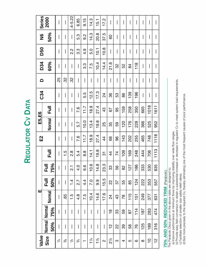
Reduced Seats—Spence Regulators are available with a choiceof seat sizes called Full and Normal Ports. There is a capacitytable for each port with standard plugs. The Cv Valve Coefficientsshown on the back page, indicate where 75% and 50%parabolic plugs are available. For a given pressure drop, ratedflows with various ports and plugs in the same size body may becompared. Thus, valve and port size may be selected to limitvelocities entering and leaving the regulator. Lower velocitiesmean a greater proportion of the pressure drop occurs at thevalve seat, where it belongs, rather than in the body outlet andconnected piping.
Capacity ratings apply to Spence Regulators with Type D, N andQ Pilots which are spring loaded and have 31/2 inch diaphragms.Other pilots having greater or lesser sensitivity will provideproportionally greater or less accuracy of regulation.
TYPICAL REGULATION CURVE
The performance characteristic of a Spence Pressure Regulatoris shown above. Using this curve to illustrate several terms ofreference, the following facts are evident:
REGULATED VARIABLE REDUCED PRESSUREMinimum Controlled Flow…………………………4%
Set Point …………………………………………25.0
Reduced Pressure at Rated (100%) Flow …22.5 psi
Accuracy of Regulation, psi …………………2.5 psi
Accuracy of Regulation, % of set pressure ……10%
The slight slope of the curve establishes a definite relationshipbetween flow and regulated pressure. Note that 1 psi accuracyof regulation is obtainable at 95% of rated flow.
For back pressure regulation, or differential where the regulatoropens on increasing differential, the characteristic curve would lieopposite to that shown. It would slope upward with flow increasebecause a positive deviation is required to cancel valve opening.
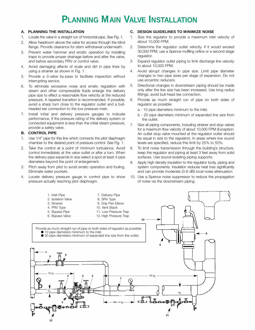
PLANNING MAIN VALVE INSTALLATIONA. PLANNING THE INSTALLATION1. Locate the valve in a straight run of horizontal pipe. See Fig. 1.2. Allow headroom above the valve for access through the blind
flange. Provide clearance for stem withdrawal underneath.3. Prevent water hammer and erratic operation by installing
traps to provide proper drainage before and after the valve,and before secondary PRV or control valve.
4. Avoid damaging affects of scale and dirt in pipe lines byusing a strainer as shown in Fig. 1 .
5. Provide a 3-valve by-pass to facilitate inspection withoutinterrupting service.
6. To eliminate excessive noise and erratic regulation withsteam and other compressible fluids enlarge the deliverypipe size to effect a reasonable flow velocity at the reducedpressure. A tapered transition is recommended. If possible,avoid a sharp turn close to the regulator outlet and a bull-headed tee connection to the low pressure main.
7. Install initial and delivery pressure gauges to indicateperformance. If the pressure rating of the delivery system orconnected equipment is less than the initial steam pressure,provide a safety valve.
B. CONTROL PIPE1. Use 1/4” pipe for this line which connects the pilot diaphragm
chamber to the desired point of pressure control. See Fig. 1.2. Take the control at a point of minimum turbulence. Avoid
control immediately at the valve outlet or after a turn. Whenthe delivery pipe expands in size select a spot at least 4 pipediameters beyond the point of enlargement.
3. Pitch away from pilot to avoid erratic operation and fouling.Eliminate water pockets.
4. Locate delivery pressure gauge in control pipe to showpressure actually reaching pilot diaphragm.
C. DESIGN GUIDELINES TO MINIMIZE NOISE1. Size the regulator to provide a maximum inlet velocity of
about 10,000 FPM.2. Determine the regulator outlet velocity. if it would exceed
30,000 FPM, use a Spence muffling orifice or a second stageregulator.
3 Expand regulator outlet piping to limit discharge line velocityto about 10,000 FPM.
4. Avoid abrupt changes in pipe size. Limit pipe diameterchanges to two pipe sizes per stage of expansion. Do notuse eccentric reducers.
5. Directional changes in downstream piping should be madeonly after the line size has been increased. Use long radiusfittings; avoid bull-head tee connection.
6. Provide as much straight run of pipe on both sides ofregulator as possible:a - 10 pipe diameters minimum to the inlet.b - 20 pipe diameters minimum of expanded line size from
the outlet.7. Size all piping components, including strainer and stop valves
for a maximum flow velocity of about 10,000 FPM (Exception:An outlet stop valve mounted at the regulator outlet shouldbe equal in size to the regulator). In areas where low soundlevels are specified, reduce this limit by 25% to 50%.
8. To limit noise transmission through the building’s structure.keep the regulator and piping at least 3 feet away from solidsurfaces. Use sound-isolating piping supports.
9. Apply high density insulation to the regulator body, piping andsystem components. Insulation reduces heat loss significantlyand can provide moderate (3-6 dB) local noise attenuation.
10. Use a Spence noise suppressor to reduce the propagationof noise via the downstream piping.
1. Inlet Pipe2. Isolation Valve3. Strainer4. PRV Type5. Bypass Pipe6. Bypass Valve
7. Delivery Pipe8. SRV Type9. Drip Pan Elbow
10. Vent Stack11. Low Pressure Trap12. High Pressure Trap
1
2 4 2
12
11
9
3
5 6
10
7
8
d1 d2
10 d120 d2
Min. 4 d2
Provide as much straight run of pipe on both sides of regulator as possible:● 10 pipe diameters minimum to the inlet.● 20 pipe diameters minimum of expanded line size from the outlet.
RULES FOR MAIN VALVE SELECTION
RULES FOR MAIN VALVE SELECTION–STEAM SERVICE
RULES FOR MAIN VALVE SELECTION–AIR SERVICE
RULES FOR MAIN VALVE SELECTION–WATER SERVICE
When you select a Main Valve, your sizing can be based onone of three methods. They are:
ECONOMICAL MAIN VALVE
Economical Main Valve Selection is choosing a regulator thathas the line size and rough capacity to handle the load. Noconsideration is given to velocities or noise. If you areinterested in an economical selection, select a regulator typefor your application, then go to the Capacity Tables and selectthe size that will provide you with the capacity needed.
ENGINEERED MAIN VALVE
Engineered Main Valve Selection takes into consideration theinlet and outlet velocities of the regulator, It will limit thesevelocities to acceptable standards. See Pressure ReducingStation Design Guidelines on the following pages for details. Ifyou are interested in an engineered selection, select a regulator
type for your application, and then to the Capacity Tables andselect the size that will provide you with the capacity needed.Verify that the velocities fall within the guidelines by consultingthe Velocity Charts in this Section.
ENGINEERED MAIN VALVE WITH NOISE SUPPRESSION
Engineered Main Valve Selection with Noise Suppressionconsiders both velocity and noise suppression in the selectionof the regulator. For this selection, it is recommended that youcontact your local Spence Technical Sales Representative whocan provide you with a computer generated solution.
SELECTING A REGULATOR TYPE
The following rules should be used to help you to determinethe type of regulator that you should use. You should consultthe Product Pages, Velocity Tables and Capacity Tables foradditional information on your selection.
EITHER DEAD-END OR CONTINUOUS FLOW SERVICE
RULE 1. For Initial Pressures exceeding 15 psi:(a) TYPE E – Select when the Delivery Pressure is less than
75% of Initial Pressure. For Differential Pressures of 15-50psi, specify optional LP Spring (10 psi minimum Differ-ential Pressure is attainable by adding optional fittings).
(b) TYPE E5 – Select when the Delivery Pressure is 75%to 96%of Initial Pressure.
RULE 2. For Initial Pressures less than 15 psi:(a) TYPE E2 – Select when Initial Pressure is less than 15 psi.
Together with the following rules, reference should be made to the Main Valve Specification Table or individual Product Pages formaximum initial pressures and temperatures and “minimum differentials”for the several types of Main Valve. For pressure reductionwhere fast response time is important, but capacity and accuracy are not critical, select D50 DIRECT OPERATED REGULATOR.
Together with the following rules, reference should be made to the Main Valve Specification Table or individual Product Pages formaximum initial pressures and temperatures and “minimum differentials”for the several types of Main Valve.For pressure reductionwhere fast response time is important, but capacity and accuracy are not critical, select D50 DIRECT OPERATED REGULATOR.
EITHER DEAD-END OR CONTINUOUS FLOW SERVICE
RULE 1. For Initial Pressures exceeding 15 psi:(a) TYPE E – Select when the Delivery Pressure is less than
75% of Initial Pressure. For Differential Pressures of 15-50psi, specify optional LP Spring (10 psi minimum Differ-ential Pressure is attainable by adding optional fittings).
(b) TYPE E6 – Select when the Delivery Pressure is 75%to 93%of Initial Pressure.
(c) TYPE E5 – Select when the Delivery Pressure is 93%to 96%of Initial Pressure.
RULE 2. For Initial Pressures less than 15 psi:(a) TYPE E2 – Select when Initial Pressure is less than 15 psi.
Pilot Operated Regulators are not uniformly successful in liquid pressure reducing service unless the delivery system has unusualcushioning such as afforded by an elevated tank or large air chamber.
WATER PRESSURE REDUCING VALVES
The TYPE D34 DIRECT OPERATED VALVE was developedfor application on rapidly changing and intermittent flow to aninflexible system.RULE 1. Select TYPE D34 DIRECT OPERATED VALVE for
pressure reducing service.
FOR PILOT OPERATED WATER REGULATORSWhen a pilot operated regulator is required the following rules
for the selection of a main valve govern:
RULE 2. When pressure drop across valve exceeds 10 psi:(a) TYPE C34 -Select for all normal requirements.
(b) TYPE E6 with Dashpot-Select where high lift is desiredor special flow requirements encountered.
RULE 3. When pressure drop across valve is between 5 and10 psi:(a) TYPE E5 - Select for pressure drops not less than 5 psi.(b) TYPE E6 with Dashpot-Select if auxiliary operation is
possible.
Together with the above rules, reference should be made tothe Main Valve Specification Table for maximum initial pres-sures and temperatures and “minimum differentials” for theseveral types of Main Valves.

VALVE SIZING BY COMPUTATIONFORMULA KEY
A = Area of Pipe in (inches)2
Cv = Valve CoefficientEDR = Equivalent Direct Radiation (Sq. Ft.)
F = Pipe Area Factor (see Pipe Factors Table) q = Liquid Flow Rate, U.S. gpmft = Feet Q = Flow Rate, SCFHG = Specific Gravity T = Absolute T (T + 460)°R
∆P = Pressure Drop,P1 – P2 psi TSH = Steam Superheat (°F) = P1 = Inlet Pressure, psia (psi + 14.7) Total Steam Temp. – Saturated Steam Temp.
P2 = Reduced Pressure, psia (psi + 14.7) v = Specific Volume FT3/#
Pc = Pressure at Thermodynamic Critical Point, V = Velocity, FPMpsia (water = 3206 psia) W = Steam Flow, #/Hr.
Pv = Vapor Pressure, psia Ws = Flow, #/Hr. Superheated Steam
LOADS
GPMWATER W = 2 X Temp. Rise (°F)
GPMFUEL OIL W = 4 X Temp. Rise (°F)
CFMAIR W = 900 X Temp. Rise (°F)
f2EDRRADIATION W = 4
ABSORPTION W = 16-20 #/Hr./Ton-Hr.
STM. ATOM W = 0.1 #/Hr./#Oil
VELOCITY
STEAM V = 2.4 WvA
To avoid interpolation or solve problems beyond the scope of the table, valve sizes may be determined by calculation as follows:
P2 > .58 P1
W Cv=2.1 √∆P (P1 + P2)
P2 > .55 P1
Cv= W (1 + .0007TSH)2.1 √∆P (P1 + P2)
P2 > .5 P1
Q GT Cv= 963 √∆P (P1 + P2)
P2 > P1 – .85 ∆PS
GCv= q √∆P
SATURATEDSTEAM:
SUPERHEATEDSTEAM:
GAS:
LIQUID:
P2 < .58 P1
W Cv=1.71 P1
P2 < .55 P1
W (1 + .0007TSH)Cv=1.75 P1
P2 < .5 P1
Q √GTCv=834 P1
P2 < P1 – .85 ∆PS
G Cv= .93q √∆PS
∆PS = P1 – Pv when P2 > Pv
= P1 – (.96 – .28 Pv ) Pv when P2 < Pv∆PS √PC
SUBCRITICAL CRITICAL
SIZE
1/8
1/4
3/8
1/2
3/4
111/4
11/2
221/2
3
FACTOR
.551.01.82.95.18.31420324671
SIZE
31/2
4568101214161820
FACTOR
9512219227848175810761301169921512673
PIPE FACTORSFOR STANDARD
(SCHEDULE 40) PIPE
FLOW
STEAM W = .0433 x V x Fv
AIR & GASES Q = .0259 x V x F x P1T
LIQUIDS q = .0054 x V x F
Cv
PRESSURE REDUCING STATION DESIGN GUIDELINES
PRESSURE REDUCING STATION GENERAL SPECIFICATION
I. SINGLE STAGE PRESSURE REGULATOR
1. When to use single stage regulator:
A. When load turndown requirement is generally no greaterthan 10:1.
B. When ratio of specific volume of steam, outlet to inlet, isno greater than 3 to 1.
C. When only one reduced steam pressure level isrequired.
II. PARALLEL PRESSURE REGULATORS
1. When to use parallel pressure regulator stations:
A. When maximum specified capacity requires selection ofa pressure regulator greater than 12 inch pipe size. (Itmay be more economical to install two smaller valvesthan one very large one.)
B. When normal conditions require operation at 10% orless of specified maximum capacity for sustainedperiods.
C. When there are two distinct load requirements; i.e.,summer/winter operation.
2. When to use a pneumatically operated parallel pressureregulator station:
A. When the combined accuracy of regulation ofmechanically operated controls is unacceptable.
For Spence mechanically operated regulators normalsizing/selection results in accuracy of regulation ofapproximately 5% of set pressure. Combined accuracyof regulation of mechanically operated parallel installedregulators is approximately 10% of set pressure.
Pneumatically operated regulators equipped with resetmaintain set point within 1% for all sustained flows.
III. TWO STAGE PRESSURE REGULATORS†
1. When to use two stage pressure regulator stations:
A. When intermediate steam pressure is required.
B. When concerned with PRV generated noise, use twostage station when specific volume ratio, outlet to inlet, isgreater than 3 to 1, unless manufacturer offersassurance or other means of meeting noise specification.
C. When complying with Power Piping Code ANSI B31.1-1986, which reads, in part, “in district heating and steamdistribution systems where the steam pressure does notexceed 400 psi (2758 kPa) and where the use of reliefvalves and vent piping are not feasible, two or morepressure reducing valves may be installed in series, eachset at or below the safe working pressure of equipmentserved and no relief valve is required.”
IV. TWO STAGEPARALLEL PRESSURE REGULATORS†
1. Whenever any condition from II and any condition from IIIapplies.
SPACE CONSIDERATIONS FOR REDUCING STATIONS
1. Following are rules of thumb for approximating spacerequirements for installing reducing stations:
A. Single stage (with or without noise suppressors)
Inlet side: ten (10) diameters of PRV pipe size
Outlet side: twenty (20) diameters of final pipe size, wherefinal pipe size is determined on the basis of 10,000 fpmline velocity.
B. Two stage
Inlet side of primary: ten (10) diameters of PRV pipe size.
Intermediate: twenty (20) diameters of secondary PRV pipesize.
Outlet side: twenty (20) diameters of final pipe size, wherefinal pipe size is determined on the basis of 10,000 fpmline velocity.
C. Two stage with muffling orifice; same as A above.
A.Pressure Reducing Station shall consist of:
- pressure regulator- inlet strainer- inlet and outlet stop valves (gate type)- by-pass valve (globe type)- trap at inlet to pressure regulator- pressure gauges on inlet and outlet of station- pressure relief valve downstream of regulator
B.Stop valves and strainer shall be at least pressure regulator size
C.Expand pressure regulator outlet pipe size to obtaindischarge line velocity which will not exceed:
Up to and including 2” 15,000 FPM2 1/2” up to 8” 10,000 FPMAbove 8” 8,000 FPM
Regulator outlet velocity shall be limited to:
Up to and including 2” 45,000 FPM2 1/ 2” up to 8” 30,000 FPMAbove 8” 24,000 FPM
D.Unions shall be used on either side of screwed end by-pass valve and pressure regulator to facilitate removal.
E.Pressure regulators 2-1/2” and larger shall have flangedends and be suitable for pressure and temperaturespecified.
F. Limit pressure regulator inlet velocity to:
Up to and including 2” 15,000 FPM2 1/2” thru 8” 10,000 FPMAbove 8” 8,000 FPM
G.Regulator sound pressure level while operating at specifiedmaximum capacity shall not exceed 90 dbA as measuredat a point three feet downstream and three feet fromuninsulated pipe surface.
H.Pressure regulator capacity shall not be greater than 120 ofspecified maximum capacity.
I. For details of safety valve sizing and installation, pleaserefer to the latest National Board Inspection Code andANSI B31.1 Code.
† Primary PRV requires optional base bypass and 1/8" bleedport.
Valv
eE
E2
E5,
E6
C34
DD
34D
50N
6Se
ries
Siz
eNo
rmal
Norm
alNo
rmal
Full
Full
Full
Norm
alFu
ll20
0050
%75
%50
%75
%60
%50
%
1 /4—
——
——
——
——
—.2
5—
——
—3 /8
——
.65
——
1.5
——
——
.32
——
——
1 /2—
—1.
51.
42.
12.
8—
——
—.3
2—
2.2
—.4
-5.2
23 /4
——
4.8
2.7
4.0
5.4
7.6
5.7
7.6
——
—3.
35.
36.
85
1—
—7.
54.
46.
68.
811
.710
.011
.75.
5—
3.3
4.9
9.2
9.15
11 /4—
—10
.47.
010
.614
.118
.913
.418
.912
.5—
7.5
5.0
14.3
14.3
11 /2—
—14
.69.
914
.819
.827
.419
.827
.417
.3—
10.4
10.1
20.8
15.1
2—
—17
.615
.523
.331
4425
4324
—14
.410
.837
.517
.2
21 /212
1824
2233
4468
3567
36—
21.6
—60
—
322
3343
3756
7496
5995
53—
32—
——
439
5978
5582
109
143
120
159
86—
52—
——
558
8711
585
127
169
202
176
258
139
—84
——
—
676
114
151
124
186
248
255
228
350
196
—11
8—
——
812
518
724
922
233
344
446
536
666
5—
——
——
—
1018
928
337
735
353
070
674
852
510
18—
——
——
—
1231
647
463
155
783
511
1311
1895
216
11—
——
——
—
REG
ULA
TOR
CV
DAT
A
75%
AN
D 5
0% R
ED
UC
ED
TR
IM (P
arab
olic
)Th
e P
arab
olic
Dis
cs g
iven
in t
he a
bove
tab
le a
re d
esig
ned
to:
a)Im
prov
e pe
rform
ance
at
min
imum
flow
s by
impr
ovin
g st
abilit
y ov
er w
ide
flow
ran
ges.
b)P
rovi
de e
asy
field
con
vers
ion
to o
btai
n a
subs
tant
ial i
ncre
ase
or d
ecre
ase
in r
egul
ator
Cv
to m
eet
syst
em lo
ad r
equi
rem
ents
.c)
Faci
litat
e se
lect
ion
of s
mal
ler
size
saf
ety
relie
f val
ves.
d)S
ize
mor
e pr
ecis
ely
to t
he r
equi
red
Cv,
the
reby
elim
inat
ing
one
of t
he m
ost
frequ
ent
caus
es o
f poo
r pe
rform
ance
.

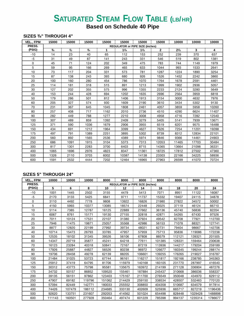
SATURATED STEAM FLOW TABLE (LB/HR)Based on Schedule 40 Pipe
VEL., FPM 45000 45000 45000 45000 45000 45000 45000 45000PRESS.(PSIG) 1/4 3/8 1/2 3/4 1 11/4 11/2 2
-10 23 43 68 120 195 337 458 755-5 51 93 148 260 422 730 994 16380 73 134 213 373 605 1046 1424 23485 97 178 284 498 807 1396 1900 313210 120 220 350 613 994 1720 2342 386015 142 260 415 728 1179 2041 2778 457920 164 301 479 841 1363 2359 3210 529225 186 341 543 953 1545 2673 3639 599830 208 381 607 1065 1726 2987 4065 670040 251 460 732 1285 2083 3605 4906 808750 293 538 857 1504 2437 4217 5740 946160 336 616 981 1721 2789 4827 6570 1082970 377 692 1102 1934 3134 5424 7383 1217080 420 770 1225 2150 3485 6031 8209 1353190 461 846 1347 2364 3831 6630 9024 14874100 503 922 1468 2577 4176 7228 9838 16216125 607 1113 1771 3108 5037 8718 11866 19558150 710 1302 2072 3636 5893 10198 13881 22879175 813 1491 2374 4166 6752 11685 15905 26216200 916 1680 2675 4694 7608 13166 17921 29539250 1121 2057 3274 5746 9313 16118 21938 36160300 1336 2452 3902 6848 11099 19209 26145 43094
REGULATOR or PIPE SIZE (inches)
SIZES 1/4" THROUGH 2"
SIZES 21/2" THROUGH 12"VEL., FPM 30000 30000 30000 30000 30000 30000 24000 24000
PRESS.(PSIG) 21/2 3 4 5 6 8 10 12
-10 718 1109 1910 3002 4335 7507 9466 13437-5 1558 2405 4142 6509 9399 16276 20524 291340 2233 3448 5938 9331 13475 23334 29424 417675 2979 4600 7922 12449 17978 31131 39256 5572310 3671 5669 9762 15341 22154 38362 48374 6866615 4356 6725 11581 18200 26283 45512 57390 8146420 5033 7772 13383 21032 30372 52594 66320 9413925 5705 8809 15170 23839 34426 59613 75171 10670330 6373 9841 16947 26632 38459 66596 83977 11920340 7692 11878 20454 32143 46418 80378 101355 14387150 9000 13896 23929 37605 54305 94036 118578 16831860 10301 15905 27389 43042 62156 107631 135722 19265370 11576 17874 30779 48370 69851 120955 152523 21650280 12870 19873 34221 53779 77662 134481 169579 24071390 14148 21846 37619 59119 85373 147834 186417 264614100 15424 23817 41012 64452 93074 161169 203233 288484125 18603 28725 49465 77735 112256 194385 245117 347938150 21763 33603 57865 90936 131319 227395 286743 407024175 24936 38503 66303 104197 150470 260557 328560 466382200 28097 43384 74708 117405 169544 293586 370208 525501250 34395 53108 91453 143720 207545 359389 453186 643286300 40991 63293 108992 171283 247348 428313 540098 766655
REGULATOR or PIPE SIZE (inches)
SATURATED STEAM FLOW TABLE (LB/HR)Based on Schedule 40 Pipe
VEL., FPM 15000 15000 15000 15000 15000 15000 15000 10000 10000 10000PRESS.(PSIG) 3/8 1/2 3/4 1 11/4 11/2 2 21/2 3 4
-10 14 23 40 65 112 153 252 239 370 637-5 31 49 87 141 243 331 546 519 802 13810 45 71 124 202 349 475 783 744 1149 19795 59 95 166 269 465 633 1044 993 1533 264110 73 117 204 331 573 781 1287 1224 1890 325415 87 138 243 393 680 926 1526 1452 2242 386020 100 160 280 454 786 1070 1764 1678 2591 446125 114 181 318 515 891 1213 1999 1902 2936 505730 127 202 355 575 996 1355 2233 2124 3280 564940 153 244 428 694 1202 1635 2696 2564 3959 681850 179 286 501 812 1406 1913 3154 3000 4632 797660 205 327 574 930 1609 2190 3610 3434 5302 913070 231 367 645 1045 1808 2461 4057 3859 5958 1026080 257 408 717 1162 2010 2736 4510 4290 6624 1140790 282 449 788 1277 2210 3008 4958 4716 7282 12540100 307 489 859 1392 2409 3279 5405 5141 7939 13671125 371 590 1036 1679 2906 3955 6519 6201 9575 16488150 434 691 1212 1964 3399 4627 7626 7254 11201 19288175 497 791 1389 2251 3895 5302 8739 8312 12834 22101200 560 892 1565 2536 4389 5974 9846 9366 14461 24903250 686 1091 1915 3104 5373 7313 12053 11465 17703 30484300 817 1301 2283 3700 6403 8715 14365 13664 21098 36331400 1065 1696 2976 4823 8347 11361 18725 17812 27502 47360500 1326 2110 3703 6002 10387 14138 23303 22166 34225 58936600 1591 2532 4444 7202 12464 16965 27963 26599 41070 70724
REGULATOR or PIPE SIZE (inches)
VEL., FPM 10000 10000 10000 8000 8000 8000 8000 8000 8000 8000PRESS.(PSIG) 5 6 8 10 12 14 16 18 20 24
-10 1001 1445 2502 3155 4479 5413 7071 8951 11122 16087-5 2170 3133 5425 6841 9711 11737 15332 19407 24115 348780 3110 4492 7778 9808 13922 16826 21980 27822 34572 500025 4150 5993 10377 13085 18574 22448 29325 37119 46124 6671010 5114 7385 12787 16125 22889 27662 36136 45740 56836 8220415 6067 8761 15171 19130 27155 32818 42871 54265 67430 9752620 7011 10124 17531 22107 31380 37924 49542 62708 77921 11270025 7946 11475 19871 25057 35568 42986 56153 71078 88321 12774130 8877 12820 22199 27992 39734 48021 62731 79404 98667 14270640 10714 15473 26793 33785 47957 57959 75713 95836 119086 17223850 12535 18102 31345 39526 56106 67808 88579 112121 139321 20150560 14347 20719 35877 45241 64218 77611 101385 128331 159464 23063870 16123 23284 40318 50841 72167 87219 113936 144217 179204 25918980 17926 25887 44827 56526 80238 96972 126677 160345 199244 28817490 19706 28458 49278 62139 88205 106601 139255 176265 219027 316787100 21484 31025 53723 67744 96161 116217 151817 192166 238785 345363125 25912 37419 64795 81706 115979 140168 183105 231770 287997 416540150 30312 43773 75798 95581 135675 163972 214199 271128 336904 487276175 34732 50157 86852 109520 155461 187884 245437 310668 386036 558337200 39135 56151 97862 123403 175167 211700 276549 350048 434970 629112250 47907 69182 119796 151062 214429 259150 338534 428507 532463 770120300 57094 82449 142771 180033 255552 308850 404358 510687 634579 917814400 74426 107479 186112 234685 333130 402609 525936 665717 827219 1196436500 92620 133751 231607 292053 414562 501024 654498 828448 1029428 1488898600 111143 160501 277928 350464 497474 601229 785398 994137 1235314 1786677
REGULATOR or PIPE SIZE (inches)
SIZES 3/8" THROUGH 4"
SIZES 5" THROUGH 24"
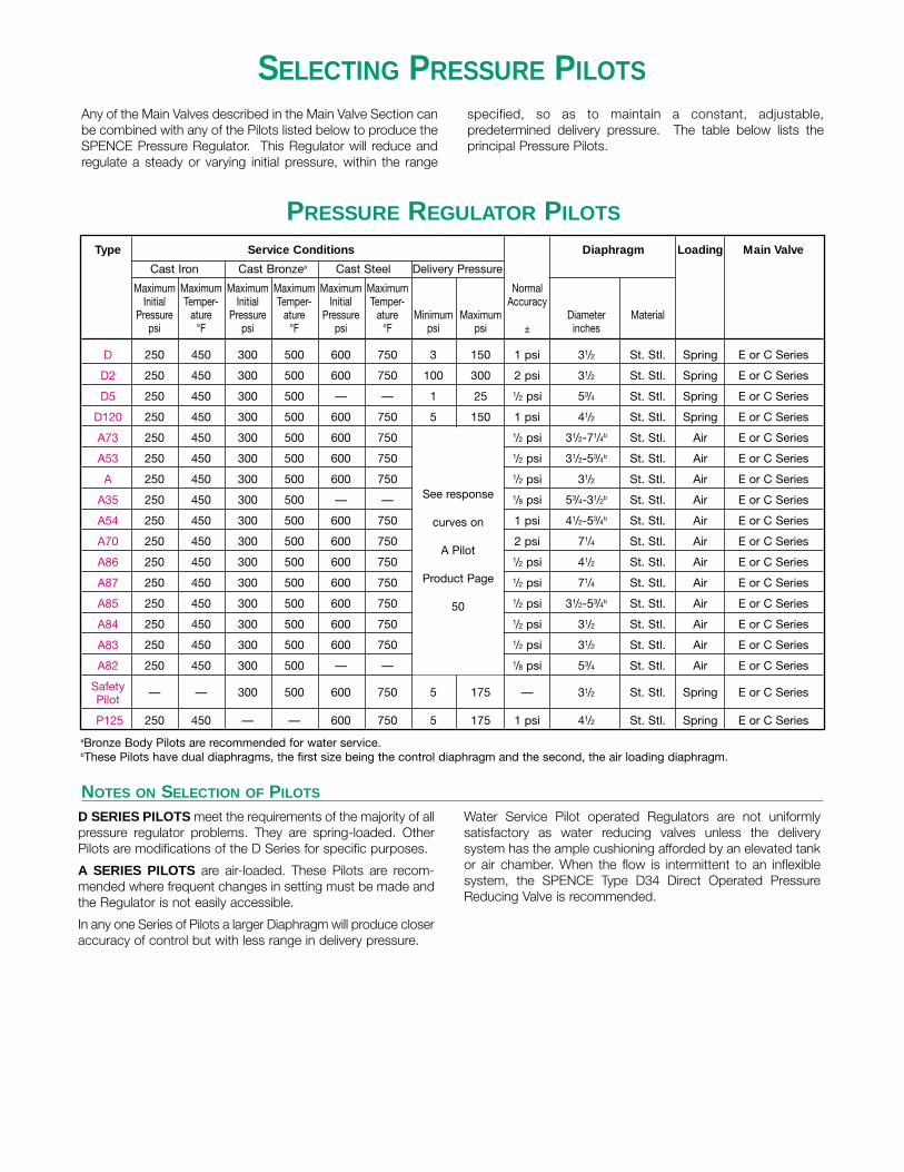
SELECTING PRESSURE PILOTSAny of the Main Valves described in the Main Valve Section canbe combined with any of the Pilots listed below to produce theSPENCE Pressure Regulator. This Regulator will reduce andregulate a steady or varying initial pressure, within the range
specified, so as to maintain a constant, adjustable,predetermined delivery pressure. The table below lists theprincipal Pressure Pilots.
D SERIES PILOTS meet the requirements of the majority of allpressure regulator problems. They are spring-loaded. OtherPilots are modifications of the D Series for specific purposes.
A SERIES PILOTS are air-loaded. These Pilots are recom-mended where frequent changes in setting must be made andthe Regulator is not easily accessible.
In any one Series of Pilots a larger Diaphragm will produce closeraccuracy of control but with less range in delivery pressure.
Water Service Pilot operated Regulators are not uniformlysatisfactory as water reducing valves unless the deliverysystem has the ample cushioning afforded by an elevated tankor air chamber. When the flow is intermittent to an inflexiblesystem, the SPENCE Type D34 Direct Operated PressureReducing Valve is recommended.
Type Service Conditions Diaphragm Loading Main Valve
Cast Iron Cast Bronzea Cast Steel Delivery Pressure
Maximum Maximum Maximum Maximum Maximum Maximum NormalInitial Temper- Initial Temper- Initial Temper- Accuracy
Pressure ature Pressure ature Pressure ature Minimum Maximum Diameter Materialpsi °F psi °F psi °F psi psi ± inches
D 250 450 300 500 600 750 3 150 1 psi 31/2 St. Stl. Spring E or C Series
D2 250 450 300 500 600 750 100 300 2 psi 31/2 St. Stl. Spring E or C Series
D5 250 450 300 500 — — 1 25 1/2 psi 53/4 St. Stl. Spring E or C Series
D120 250 450 300 500 600 750 5 150 1 psi 41/2 St. Stl. Spring E or C Series
A73 250 450 300 500 600 750 1/2 psi 31/2-71/4b St. Stl. Air E or C Series
A53 250 450 300 500 600 750 1/2 psi 31/2-53/4b St. Stl. Air E or C Series
A 250 450 300 500 600 750 1/2 psi 31/2 St. Stl. Air E or C Series
A35 250 450 300 500 — — 1/8 psi 53/4-31/2b St. Stl. Air E or C Series
A54 250 450 300 500 600 750 1 psi 41/2-53/4b St. Stl. Air E or C Series
A70 250 450 300 500 600 750 2 psi 71/4 St. Stl. Air E or C Series
A86 250 450 300 500 600 750 1/2 psi 41/2 St. Stl. Air E or C Series
A87 250 450 300 500 600 750 1/2 psi 71/4 St. Stl. Air E or C Series
A85 250 450 300 500 600 750 1/2 psi 31/2-53/4b St. Stl. Air E or C Series
A84 250 450 300 500 600 750 1/2 psi 31/2 St. Stl. Air E or C Series
A83 250 450 300 500 600 750 1/2 psi 31/2 St. Stl. Air E or C Series
A82 250 450 300 500 — — 1/8 psi 53/4 St. Stl. Air E or C Series
SafetyPilot
— — 300 500 600 750 5 175 — 31/2 St. Stl. Spring E or C Series
P125 250 450 — — 600 750 5 175 1 psi 41/2 St. Stl. Spring E or C Series
aBronze Body Pilots are recommended for water service.bThese Pilots have dual diaphragms, the first size being the control diaphragm and the second, the air loading diaphragm.
See response
curves on
A Pilot
Product Page
50
PRESSURE REGULATOR PILOTS
NOTES ON SELECTION OF PILOTS

SIZING PRESSURE REGULATORS
DATA REQUIRED FOR ORDERING
1. SERVICE Fluid flowing though Regulator.
2. INITIAL (INLET) PRESSURE
(a) Maximum/Minimum.
(b) Superheat, Gravity, etc.
(1) Steam Service–Total Temperature or DegreesSuperheat, if any.
(2) Air, Gases, Water and Liquids–Temperature andSpecific Gravity.
3. DELIVERY (OUTLET) PRESSURE Maximum/Minimum.
4. CAPACITY Maximum required flow through Regulator.
5. END CONNECTIONS Screwed or Flanged. (If flanged,state drilling.)
SELECTION OF TYPE AND SIZE OF REGULATOR
MAIN VALVE
A. TYPE —See Selection Criteriafor Steam, Air, Gases or Waterand Liquids in beginning of thisSection.
B. SIZE—See applicable ValveCapacity Tables in this Section.
C. MATERIAL— See Main ValveSelection Chart in TechnicalReference Section or individualProduct Pages.
D. ACCESSORIES—See Accessories in Other ProductsSection.
EXAMPLESelect size and type Regulator to pass 14,600 lb. steam perhour reducing from 175/150 psi saturated to 40/20 psi. Endsto be flanged, pilot spring loaded and pressure controlledwithin 2 psi.
1. Steam
2.
(a) 175/150 psi
(b) None (saturated, 378°F total temperature)
3. 40/20 psi
4. 14,600 lb. per hour5. Flanged, if 21/2" size or larger
SELECTION OF TYPE AND SIZE OF REGULATOR
MAIN VALVE
A. Since maximum DeliveryPressure is less than 75%of minimum Initial Pressureand the least pressure dropexceeds required “minimaldifferential”.SELECT TYPE E
B. For 14,600 lb. per hour and 150 psi minimum Initial Pressure Economical:SELECT 3" FULL PORTEngineered: SELECT 4"NORMAL PORT
C. For 175 psi, 378°F:SELECT CAST IRON,FLANGED 250 LB.
D. None required in this case.
ECONOMICAL SOLUTION: 3" FULL PORT SPENCE TYPE ED, CAST IRON BODY, 250 LB. FLANGED ENDSENGINEERED SOLUTION: 4" NORMAL PORT SPENCE TYPE ED, CAST IRON BODY, 250 LB. FLANGED ENDS.
NOTE:Pressure Regulators should always be protected by properly designed Strainers.
PILOT
See Selection Criteriaand Selection Chartsopposite.
See Pilot SelectionChart opposite or indi-vidual Product Pages.
PILOT
Since maximum InitialPressure 175 psi, TotalTemperature 378°F maxi-mum Delivery Pressure 40psi, Pilot spring loaded andrequired accuracy 2 psi:SELECT TYPE D
For 175 psi, 378°F:SELECT CAST IRON
None required in this case.
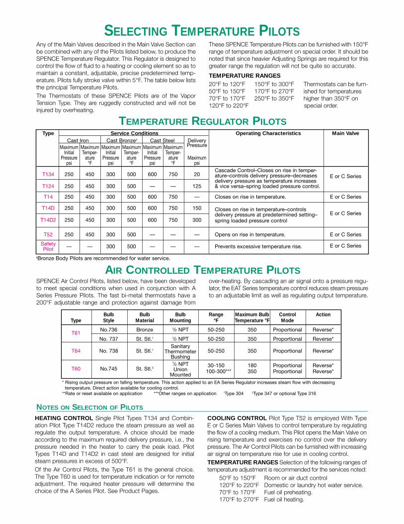
SELECTING TEMPERATURE PILOTSAny of the Main Valves described in the Main Valve Section canbe combined with any of the Pilots listed below, to produce theSPENCE Temperature Regulator. This Regulator is designed tocontrol the flow of fluid to a heating or cooling element so as tomaintain a constant, adjustable, precise predetermined temp-erature. Pilots fully stroke valve within 5°F. The table below liststhe principal Temperature Pilots.The Thermostats of these SPENCE Pilots are of the VaporTension Type. They are ruggedly constructed and will not beinjured by overheating.
These SPENCE Temperature Pilots can be furnished with 150°Frange of temperature adjustment on special order. It should benoted that since heavier Adjusting Springs are required for thisgreater range the regulation will not be quite so accurate.
TEMPERATURE RANGES20°F to 120°F 150°F to 300°F Thermostats can be furn-50°F to 150°F 170°F to 270°F ished for temperatures 70°F to 170°F 250°F to 350°F higher than 350°F on 120°F to 220°F special order.
HEATING CONTROL Single Pilot Types T134 and Combin-ation Pilot Type T14D2 reduce the steam pressure as well asregulate the output temperature. A choice should be madeaccording to the maximum required delivery pressure, i.e., thepressure needed in the heater to carry the peak load. PilotTypes T14D and T14D2 in cast steel are designed for initialsteam pressures in excess of 500°F.Of the Air Control Pilots, the Type T61 is the general choice.The Type T60 is used for temperature indication or for remoteadjustment. The required heater pressure will determine thechoice of the A Series Pilot. See Product Pages.
COOLING CONTROL Pilot Type T52 is employed With TypeE or C Series Main Valves to control temperature by regulatingthe flow of a cooling medium. This Pilot opens the Main Valve onrising temperature and exercises no control over the deliverypressure. The Air Control Pilots can be furnished with increasingair signal on temperature rise for use in cooling control.TEMPERATURE RANGES Selection of the following ranges oftemperature adjustment is recommended for the services noted:
50°F to 150°F Room or air duct control120°F to 220°F Domestic or laundry hot water service.70°F to 170°F Fuel oil preheating.170°F to 270°F Fuel oil heating.
Type Service Conditions Operating Characteristics Main ValveCast Iron Cast Bronzea Cast Steel Delivery
Maximum Maximum Maximum Maximum Maximum Maximum PressureInitial Temper- Initial Temper- Initial Temper-
Pressure ature Pressure ature Pressure ature Maximumpsi °F psi °F psi °F psi
T134 250 450 300 500 600 750 20Cascade Control–Closes on rise in temper-ature–controls delivery pressure–decreases E or C Series
T124 250 450 300 500 — — 125delivery pressure as temperature increases & vice versa–spring loaded pressure control.
T14 250 450 300 500 600 750 — Closes on rise in temperature. E or C Series
T14D 250 450 300 500 600 750 150 Closes on rise in temperature–controlsdelivery pressure at predetermined setting– E or C Series
T14D2 250 450 300 500 600 750 300 spring loaded pressure control
T52 250 450 300 500 — — — Opens on rise in temperature. E or C Series
SafetyPilot — — 300 500 — — — Prevents excessive temperature rise. E or C Series
aBronze Body Pilots are recommended for water service.
* Rising output pressure on falling temperature. This action applied to an EA Series Regulator increases steam flow with decreasingtemperature. Direct action available for cooling control.
**Rate or reset available on application ***Other ranges on application 1Type 304 2Type 347 or optional Type 316
TEMPERATURE REGULATOR PILOTS
AIR CONTROLLED TEMPERATURE PILOTS
NOTES ON SELECTION OF PILOTS
SPENCE Air Control Pilots, listed below, have been developedto meet special conditions when used in conjunction with ASeries Pressure Pilots. The fast bi-metal thermostats have a200°F adjustable range and protection against damage from
over-heating. By cascading an air signal onto a pressure regu-lator, the EAT Series temperature control reduces steam pressureto an adjustable limit as well as regulating output temperature.
Bulb Bulb Bulb Range Maximum Bulb Control ActionType Style Material Mounting °F Temperature °F Mode
No.736 Bronze 1/2 NPT 50-250 350 Proportional Reverse*T61
No. 737 St. Stl.1 1/2 NPT 50-250 350 Proportional Reverse*Sanitary
T64 No. 738 St. Stl.1 Thermometer 50-250 350 Proportional Reverse*Bushing1/2 NPT 30-150 180 Proportional Reverse*
T60 No.745 St. Stl.2 Union 100-300*** 350 Proportional Reverse*Mounted
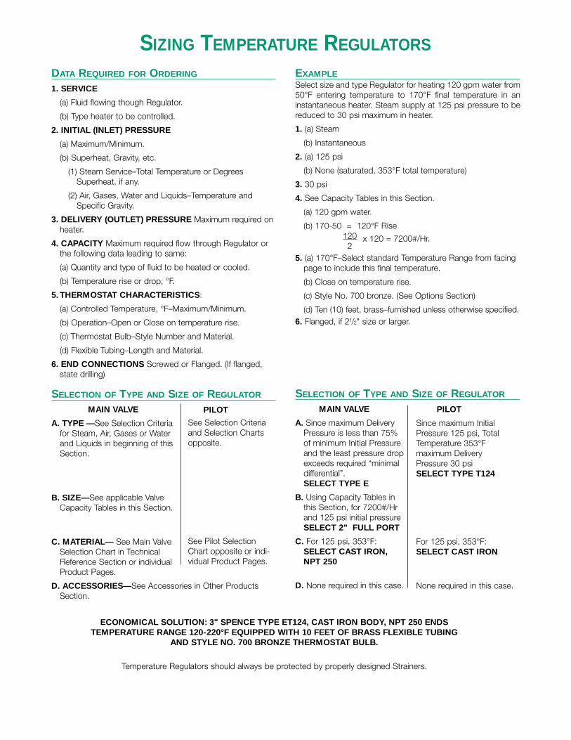
SIZING TEMPERATURE REGULATORS
DATA REQUIRED FOR ORDERING
1. SERVICE
(a) Fluid flowing though Regulator.
(b) Type heater to be controlled.
2. INITIAL (INLET) PRESSURE
(a) Maximum/Minimum.
(b) Superheat, Gravity, etc.
(1) Steam Service–Total Temperature or DegreesSuperheat, if any.
(2) Air, Gases, Water and Liquids–Temperature andSpecific Gravity.
3. DELIVERY (OUTLET) PRESSURE Maximum required onheater.
4. CAPACITY Maximum required flow through Regulator orthe following data leading to same:
(a) Quantity and type of fluid to be heated or cooled.
(b) Temperature rise or drop, °F.
5. THERMOSTAT CHARACTERISTICS:
(a) Controlled Temperature, °F–Maximum/Minimum.
(b) Operation–Open or Close on temperature rise.
(c) Thermostat Bulb–Style Number and Material.
(d) Flexible Tubing–Length and Material.
6. END CONNECTIONS Screwed or Flanged. (If flanged,state drilling)
SELECTION OF TYPE AND SIZE OF REGULATOR
MAIN VALVE
A. TYPE —See Selection Criteriafor Steam, Air, Gases or Waterand Liquids in beginning of thisSection.
B. SIZE—See applicable ValveCapacity Tables in this Section.
C. MATERIAL— See Main ValveSelection Chart in TechnicalReference Section or individualProduct Pages.
D. ACCESSORIES—See Accessories in Other ProductsSection.
EXAMPLESelect size and type Regulator for heating 120 gpm water from50°F entering temperature to 170°F final temperature in aninstantaneous heater. Steam supply at 125 psi pressure to bereduced to 30 psi maximum in heater.
1. (a) Steam
(b) Instantaneous
2. (a) 125 psi
(b) None (saturated, 353°F total temperature)
3. 30 psi
4. See Capacity Tables in this Section.
(a) 120 gpm water.
(b) 170-50 = 120°F Rise120 x 120 = 7200#/Hr.2
5. (a) 170°F–Select standard Temperature Range from facingpage to include this final temperature.
(b) Close on temperature rise.
(c) Style No. 700 bronze. (See Options Section)
(d) Ten (10) feet, brass–furnished unless otherwise specified.6. Flanged, if 21/2" size or larger.
SELECTION OF TYPE AND SIZE OF REGULATOR
MAIN VALVE
A. Since maximum DeliveryPressure is less than 75%of minimum Initial Pressureand the least pressure dropexceeds required “minimaldifferential”.SELECT TYPE E
B. Using Capacity Tables in this Section, for 7200#/Hr and 125 psi initial pressureSELECT 2" FULL PORT
C. For 125 psi, 353°F:SELECT CAST IRON,NPT 250
D. None required in this case.
PILOT
Since maximum InitialPressure 125 psi, TotalTemperature 353°F maximum Delivery Pressure 30 psi SELECT TYPE T124
For 125 psi, 353°F:SELECT CAST IRON
None required in this case.
PILOT
See Selection Criteriaand Selection Chartsopposite.
See Pilot SelectionChart opposite or indi-vidual Product Pages.
ECONOMICAL SOLUTION: 3" SPENCE TYPE ET124, CAST IRON BODY, NPT 250 ENDSTEMPERATURE RANGE 120-220°F EQUIPPED WITH 10 FEET OF BRASS FLEXIBLE TUBING
AND STYLE NO. 700 BRONZE THERMOSTAT BULB.
Temperature Regulators should always be protected by properly designed Strainers.

NOTES ON SELECTION OF PILOTS
DIFFERENTIAL PRESSURE REGULATOR PILOTS
SELECTING DIFFERENTIAL PRESSURE PILOTSSPENCE Differential Pressure Regulators may usually be classi-fied in one or the other of the following groups:
1. Control of the delivery pressure at a constant, adjustable, pre-determined differential above another source of fluid pressure.This case is illustrated by the use of the SPENCE Type ENDifferential Pressure Regulator on a boiler feedwater make-upline to control the delivery pressure of the feedwater at a con-stant differential above the boiler steam pressure. Anotherexample is the use of the Type EN to control the steam pres-
sure on a steam atomizing oil burner at a constant differentialabove the oil pressure at the nozzle.
2. Control of the differential pressure or pressure drop acrossthe Pressure Regulator itself. This case is illustrated by the useof the SPENCE Type EN24 Differential Pressure Regulatorinstalled in parallel with a heat exchanger to maintain a con-stant differential across it, thereby limiting the flow rate offluid through the heater.
The table below lists the principal Differential Pilots.
TYPE N AND N33 PILOTS require that the delivery pressure(pressure of fluid discharged from the Regulator) be controlledat a given differential above some separate source of loadingpressure.
TYPE N meets the requirements of most boiler feedwatermake-up and steam atomizing oil burner differential controlproblems as described in the first group in the above table.
TYPE N33 is a version of the Type N in which two separateddiaphragms are employed to preclude the possibility of contactbetween the two fluids applied to the pilot.
TYPE N20 is a differential relief pilot which causes the MainValve to open when its initial pressure exceeds the loadingpressure by a set differential.
Type Service Conditions Diaphragm Operating Main
Cast Iron Cast Bronzea Cast Steel Differential Characteristics Valve
Max. Max. Max. Max. Max. Max. Max. Max. Max. Pressure Normal LoadingInitial Temper- Diaph. Initial Temper- Diaph. Initial Temper- Diaph. Accuracy
Pressure ature Pressure Pressure ature Pressure Pressure ature Pressure Min. Max. Diameter Materialpsi °F psi psi °F psi psi °F psi psi psi ± inches
N 250 450 240 300 500 290 600 750 300 3 150 1 psi 31/2 St. Stl. SpringCloses on increase in differential E or CDelivery pressure controlled at set Series
N33 250 450 240 300 500 290 600 750 300 3 150 1 psi 31/2 St. Stl. Springdifferential above loading pressure E or CLoading Pressure may be any fluid SeriesOpens on increase in differential
N20 250 366 250 300 366 300 300 366 300 3 150 1 psi 31/2 St. Stl. SpringInitial pressure controlled at set E or Cdifferential above loading pressure SeriesLoading pressure may be any fluid
aBronze Body Pilots are recommended for water service.

SIZING DIFFERENTIAL PRESSURE REGULATORS
DATA REQUIRED FOR ORDERING
1. SERVICE Fluid flowing though Regulator.
2. INITIAL (INLET) PRESSURE
(a) Maximum/Minimum.
(b) Superheat, Gravity, etc.
(1) Steam Service–Total Temperature or DegreesSuperheat, if any.
(2) Air, Gases, Water and Liquids–Temperature andSpecific Gravity.
3. LOADING PRESSURE
(a) Maximum/Minimum.
(b) Fluid
4. CONTROLLED PRESSURE
(a) Maximum/Minimum.
(b) Fluid
5. DELIVERY PRESSURE Maximum/Minimum.
6. CAPACITY Maximum required flow through Regulator.
7. END CONNECTIONS Screwed or Flanged. (If flanged,state drilling.)
SELECTION OF TYPE AND SIZE OF REGULATOR
MAIN VALVE
A. TYPE —See Selection Criteriafor Steam, Air, Gases or Waterand Liquids in beginning of thisSection.
B. SIZE—See applicable ValveCapacity Tables in this Section.
C. MATERIAL— See Main ValveSelection Chart in TechnicalReference Section or individualProduct Pages.
D. ACCESSORIES—See Accessories in Other ProductsSection.
EXAMPLESelect size and type Regulator to control the flow of water froma Motor-Driven Centrifugal Boiler Feed Pump maintaining anExcess or Differential pressure of 50 psi between the boilerfeedwater and the boiler steam pressure. The feedwatertemperature is 240°F. The boiler steam pressure is 150 psi.Flow 90 gpm at 220 psi pump discharge pressure.
1. Water
2. (a) 220 psi
(b) 240°F
3. (a) 150 psi Boiler Pressure
(b) Steam
4. (a) 200 psi (Loading plus Excess Pressure)
(b) Water
5. Identical with Controlled Pressure, Item 4
6. 90 gpm
7. Flanged, if 21/2" size or larger
SELECTION OF TYPE AND SIZE OF REGULATOR
MAIN VALVE
A. Since pressure drop acrossvalve (Initial Pressure minusDelivery Pressure) is greaterthan 10 psi:SELECT TYPE E
B. For 90 gpm: SELECT 3"
C. For 220 psi, 240°F:SELECT CAST IRON,FLANGED 250 LB.
D. For Water Service:Dashpot required.
PILOT
Since Initial Pressure 220 psi,240°F, Differential (Excess)Pressure 50 psi and theDelivery and ControlledPressures are the same:SELECT TYPE N
For 220 psi, 240°F:SELECT BRONZE
None required in this case.
ANSWER: 3" SPENCE TYPE EN, CAST IRON BODY, 250 LB FLANGED ENDS,EQUIPPED WITH BRONZE DASHPOT AND BRONZE PILOT BODY.
NOTE: Differential Regulators should always be protected by properly designed Strainers.
PILOT
See Selection Criteriaand Selection Chartsopposite.
See Pilot SelectionChart opposite or indi-vidual Product Pages.
WATER CAPACITY TABLE–FLOW IN GALLONS PER MINUTEThese flow rates provide a simple method for sizing regulators or water pipes with inlet velocities in therange of 240 to 600 fpm. Spence Regulators have variable seat sizes. The factory will select the properseat for particular flow and pressure drop. Additional capacity data is available on request.
VALVE OR PIPE SIZE1/4 3/8 1/2 3/4 1 11/4 11/2 2 21/2 3 4 5 6 8 10 12
Velocity, fpm247 251 255 262 270 277 285 300 315 330 360 390 420 480 540 600
1.3 2.5 4.0 7.3 12 22 30 52 78 127 238 405 630 1250 2210 3490
Velocity, fpm

Type Service Conditions Diaphragm Main Valve
Cast Iron Cast Bronzea Cast Steel Delivery Pressure
Maximum Maximum Maximum Maximum Maximum Maximum NormalInitial Temper- Initial Temper- Initial Temper- Accuracy
Pressure ature Pressure ature Pressure ature Minimum Maximum Diameter Materialpsi °F psi °F psi °F psi psi ± inches
Q 150 366 150 366 150 366 3 150 1 psi 31/2 St. Stl. E or C Series
Q2 250 450 300 500 600 750 100 400 2 psi 31/2 St. Stl. E or C Series
Q73b 150 366 150 366 150 366 3 150 1/2 psi 31/2-71/4c St. Stl. E or C Series
F14 250 450 300 500 600 750 3 150 1 psi 41⁄2 St. Stl. E or C Series
F13 250 450 300 500 600 750 100 300 2 psi 31⁄2 St. Stl. E or C Series
F15 250 450 300 500 600 750 2 25 1/2 psi 53⁄4 St. Stl. E or C Series
F32 250 450 300 500 600 750 200 2000 10 psi 7⁄8 piston St. Stl. E or C Series
aBronze Body Pilots are recommended for water service. bType Q73 is air adjusted, all others are spring loaded.cThese Pilots have dual diaphragms, the first size being the control diaphragm and the second, the air loading diaphragm.
than that flowing through the regulator. Type F Series Pilots arealso recommended for usual back pressure service in the eventthat long control pipes are unavoidable.
In either series of back pressure pilots, a larger Diaphragm willproduce closer accuracy of control but with less range in backpressure.
TYPE Q SERIES meet the requirements of the majority of allback pressure problems. They are packless and spring or air loaded.The Type Q Pilot can be furnished for service on refrigerants onspecial order.
TYPE F SERIES have bellows stem seals and separate dia-phragm chambers. They are designed for applications where aregulator is required to open on rise in pressure of a fluid other
NOTES ON SELECTION OF PILOTS
SELECTING BACK PRESSURE PILOTSAny of the Main Valves described in the Main Valve Section canbe combined with any of the Pilots listed below to produce theSPENCE Back Pressure Regulator. Provided the delivery (dis-charge) pressure is sufficiently below the desired back pressureto operate the Regulator, it will maintain a steady back pressureregardless of fluctuations in the load. The Pilot is guaranteed toshut tight when the back pressure falls below a predetermined
setting. The table below lists the principal Back Pressure Pilots.THE SPENCE BACK PRESSURE REGULATOR IS NOT ASAFETY VALVE AND SHOULD NEVER BE USED AS SUCH. The discharge pressure must always be low enough in relationto the back pressure to provide the required minimum differ-ential listed in the Main Valve Selection Chart in the TechnicalReference Section.
BACK PRESSURE REGULATOR PILOTS
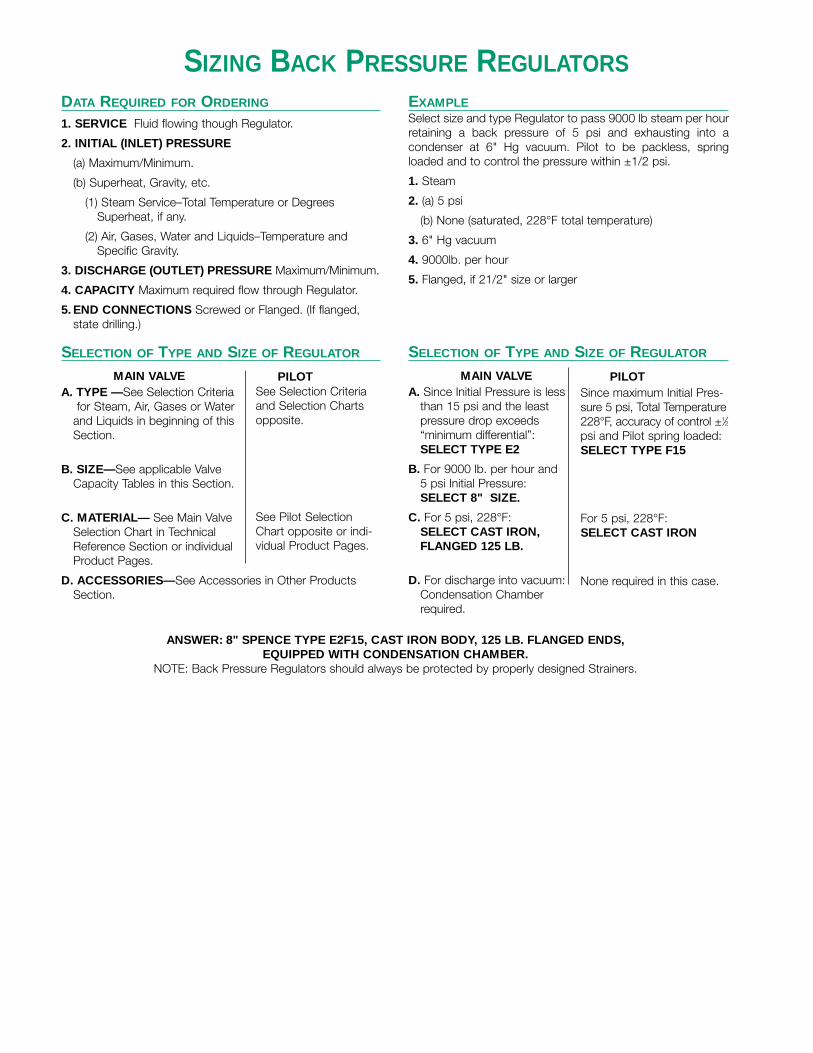
DATA REQUIRED FOR ORDERING
1. SERVICE Fluid flowing though Regulator.
2. INITIAL (INLET) PRESSURE
(a) Maximum/Minimum.
(b) Superheat, Gravity, etc.
(1) Steam Service–Total Temperature or DegreesSuperheat, if any.
(2) Air, Gases, Water and Liquids–Temperature andSpecific Gravity.
3. DISCHARGE (OUTLET) PRESSURE Maximum/Minimum.
4. CAPACITY Maximum required flow through Regulator.
5. END CONNECTIONS Screwed or Flanged. (If flanged,state drilling.)
SELECTION OF TYPE AND SIZE OF REGULATOR
MAIN VALVEA. TYPE —See Selection Criteria
for Steam, Air, Gases or Waterand Liquids in beginning of thisSection.
B. SIZE—See applicable ValveCapacity Tables in this Section.
C. MATERIAL— See Main ValveSelection Chart in TechnicalReference Section or individualProduct Pages.
D. ACCESSORIES—See Accessories in Other ProductsSection.
EXAMPLESelect size and type Regulator to pass 9000 lb steam per hourretaining a back pressure of 5 psi and exhausting into acondenser at 6" Hg vacuum. Pilot to be packless, springloaded and to control the pressure within ±1/2 psi.
1. Steam
2. (a) 5 psi
(b) None (saturated, 228°F total temperature)
3. 6" Hg vacuum
4. 9000lb. per hour
5. Flanged, if 21/2" size or larger
SELECTION OF TYPE AND SIZE OF REGULATOR
MAIN VALVEA. Since Initial Pressure is less
than 15 psi and the leastpressure drop exceeds“minimum differential”:SELECT TYPE E2
B. For 9000 lb. per hour and 5 psi Initial Pressure: SELECT 8" SIZE.
C. For 5 psi, 228°F:SELECT CAST IRON,FLANGED 125 LB.
D. For discharge into vacuum:Condensation Chamberrequired.
PILOTSince maximum Initial Pres-sure 5 psi, Total Temperature228°F, accuracy of control ±1⁄2psi and Pilot spring loaded:SELECT TYPE F15
For 5 psi, 228°F:SELECT CAST IRON
None required in this case.
PILOTSee Selection Criteriaand Selection Chartsopposite.
See Pilot SelectionChart opposite or indi-vidual Product Pages.
SIZING BACK PRESSURE REGULATORS
ANSWER: 8" SPENCE TYPE E2F15, CAST IRON BODY, 125 LB. FLANGED ENDS,EQUIPPED WITH CONDENSATION CHAMBER.
NOTE: Back Pressure Regulators should always be protected by properly designed Strainers.

SELECTING PUMP GOVERNOR PILOTSSPENCE Pump Governors are classified in four groups as follows:
1. Constant Pressure Pump Governor which is illustrated bythe SPENCE Type EP14 Pump Governor. This Regulatorgoverns the steam supply to a pump, either reciprocating orturbine-driven, and maintains a constant, adjustable pumpdischarge pressure.
2. Excess Pressure Pump Governor which is illustrated by theSPENCE Type EN Differential Pressure Regulator. Althoughthis Regulator is not a Pump Governor, it is recommended togovern the steam supply to boiler feed pump where it isdesired to maintain the pump discharge pressure at a con-stant, adjustable differential pressure in excess of the boilersteam pressure.
3. Vacuum Pump Governor which is illustrated by the SPENCEType EF46 Pump Governor. This Regulator governs thesteam supply to a vacuum pump and maintains a constant,adjustable vacuum on the pump suction.
4.Differential Control for electric motor-driven centrifugal pumpswhich is illustrated by the SPENCE Type EN DifferentialPressure Regulator. Although this Regulator is not a PumpGovernor, it is recommended to maintain a constant, adjust-able differential between the feedwater pressure and the boilersteam pressure; i.e., a constant pressure drop across thefeedwater regulator.
The table below lists the principal Pump Governor Pilots.
P SERIES PILOTS are used for constant pressure control. Inthis Series a larger Diaphragm will produce closer accuracy ofcontrol but with less range in pump discharge pressure.
TYPE F46 is a vacuum pump governor Pilot.
TYPE N is a differential pressure Pilot which is applied to thedischarge of a constant speed centrifugal pump to effect
excess pressure control. The design of the Pilot requires thatthe delivery pressure (pressure of fluid discharged from Regu-lator) be controlled at a given differential above some separatesource of loading pressure. In typical service, boiler feedwaterflows through the Regulator and is delivered at constant excesspressure above the boiler steam pressure.
Type Service Conditions Diaphragm Main Valve Type of Control
Cast Iron Cast Bronzea Cast Steel Pump Discharge
Maximum Maximum Maximum Maximum Maximum Maximum PressureInitial Temper- Initial Temper- Initial Temper-
Pressure ature Pressure ature Pressure ature Minimum Maximum Diameter Materialpsi °F psi °F psi °F psi psi inches
P13 250 450 300 500 600 750 100 300 31/2 St. Stl. E or C Series Constant Pressure
P14 250 450 300 500 600 750 5 150 41/2 St. Stl. E or C Series Constant Pressure
P15 250 450 300 500 600 750 3 25 53/4 St. Stl. E or C Series Constant Pressure
P32 250 450 300 500 600 750 200 20007/8 St. Stl. E or C Series Constant Pressure
Piston
F46 250 450 300 500 600 750 0 30” 41/2 St. Stl. E or C Series VacuumHg vac
N 250 450 300 500 600 500 3b 300b 31/2 St. Stl. E or C Series Differentialc
aBronze Body Pilots are recommended for water service. bRegulator discharge pressure cFor electric motor driven centrifugal pump applications only, differential pressure range 3 to 150 psi
PUMP GOVERNOR PILOTS
NOTES ON SELECTION OF PILOTS
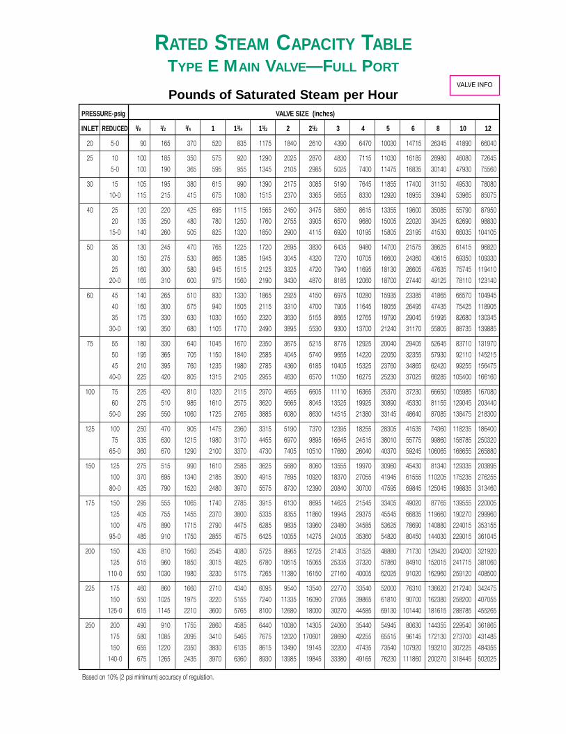
RATED STEAM CAPACITY TABLETYPE E MAIN VALVE—FULL PORT
Pounds of Saturated Steam per HourPRESSURE-psig VALVE SIZE (inches)
INLET REDUCED 3/8 1/2 3/4 1 11/4 11/2 2 21/2 3 4 5 6 8 10 12
20 5-0 90 165 370 520 835 1175 1840 2610 4390 6470 10030 14715 26345 41890 66040
25 10 100 185 350 575 920 1290 2025 2870 4830 7115 11030 16185 28980 46080 72645
5-0 100 190 365 595 955 1345 2105 2985 5025 7400 11475 16835 30140 47930 75560
30 15 105 195 380 615 990 1390 2175 3085 5190 7645 11855 17400 31150 49530 78080
10-0 115 215 415 675 1080 1515 2370 3365 5655 8330 12920 18955 33940 53965 85075
40 25 120 220 425 695 1115 1565 2450 3475 5850 8615 13355 19600 35085 55790 87950
20 135 250 480 780 1250 1760 2755 3905 6570 9680 15005 22020 39425 62690 98830
15-0 140 260 505 825 1320 1850 2900 4115 6920 10195 15805 23195 41530 66035 104105
50 35 130 245 470 765 1225 1720 2695 3830 6435 9480 14700 21575 38625 61415 96820
30 150 275 530 865 1385 1945 3045 4320 7270 10705 16600 24360 43615 69350 109330
25 160 300 580 945 1515 2125 3325 4720 7940 11695 18130 26605 47635 75745 119410
20-0 165 310 600 975 1560 2190 3430 4870 8185 12060 18700 27440 49125 78110 123140
60 45 140 265 510 830 1330 1865 2925 4150 6975 10280 15935 23385 41865 66570 104945
40 160 300 575 940 1505 2115 3310 4700 7905 11645 18055 26495 47435 75425 118905
35 175 330 630 1030 1650 2320 3630 5155 8665 12765 19790 29045 51995 82680 130345
30-0 190 350 680 1105 1770 2490 3895 5530 9300 13700 21240 31170 55805 88735 139885
75 55 180 330 640 1045 1670 2350 3675 5215 8775 12925 20040 29405 52645 83710 131970
50 195 365 705 1150 1840 2585 4045 5740 9655 14220 22050 32355 57930 92110 145215
45 210 395 760 1235 1980 2785 4360 6185 10405 15325 23760 34865 62420 99255 156475
40-0 225 420 805 1315 2105 2955 4630 6570 11050 16275 25230 37025 66285 105400 166160
100 75 225 420 810 1320 2115 2970 4655 6605 11110 16365 25370 37230 66650 105985 167080
60 275 510 985 1610 2575 3620 5665 8045 13525 19925 30890 45330 81155 129045 203440
50-0 295 550 1060 1725 2765 3885 6080 8630 14515 21380 33145 48640 87085 138475 218300
125 100 250 470 905 1475 2360 3315 5190 7370 12395 18255 28305 41535 74360 118235 186400
75 335 630 1215 1980 3170 4455 6970 9895 16645 24515 38010 55775 99860 158785 250320
65-0 360 670 1290 2100 3370 4730 7405 10510 17680 26040 40370 59245 106065 168655 265880
150 125 275 515 990 1610 2585 3625 5680 8060 13555 19970 30960 45430 81340 129335 203895
100 370 695 1340 2185 3500 4915 7695 10920 18370 27055 41945 61555 110205 175235 276255
80-0 425 790 1520 2480 3970 5575 8730 12390 20840 30700 47595 69845 125045 198835 313460
175 150 295 555 1065 1740 2785 3915 6130 8695 14625 21545 33405 49020 87765 139555 220005
125 405 755 1455 2370 3800 5335 8355 11860 19945 29375 45545 66835 119660 190270 299960
100 475 890 1715 2790 4475 6285 9835 13960 23480 34585 53625 78690 140880 224015 353155
95-0 485 910 1750 2855 4575 6425 10055 14275 24005 35360 54820 80450 144030 229015 361045
200 150 435 810 1560 2545 4080 5725 8965 12725 21405 31525 48880 71730 128420 204200 321920
125 515 960 1850 3015 4825 6780 10615 15065 25335 37320 57860 84910 152015 241715 381060
110-0 550 1030 1980 3230 5175 7265 11380 16150 27160 40005 62025 91020 162960 259120 408500
225 175 460 860 1660 2710 4340 6095 9540 13540 22770 33540 52000 76310 136620 217240 342475
150 550 1025 1975 3220 5155 7240 11335 16090 27065 39865 61810 90700 162380 258200 407055
125-0 615 1145 2210 3600 5765 8100 12680 18000 30270 44585 69130 101440 181615 288785 455265
250 200 490 910 1755 2860 4585 6440 10080 14305 24060 35440 54945 80630 144355 229540 361865
175 580 1085 2095 3410 5465 7675 12020 170601 28690 42255 65515 96145 172130 273700 431485
150 655 1220 2350 3830 6135 8615 13490 19145 32200 47435 73540 107920 193210 307225 484355
140-0 675 1265 2435 3970 6360 8930 13985 19845 33380 49165 76230 111860 200270 318445 502025
Based on 10% (2 psi minimum) accuracy of regulation.
VALVE INFO
Based on 10% (2 psi minimum) accuracy of regulation.
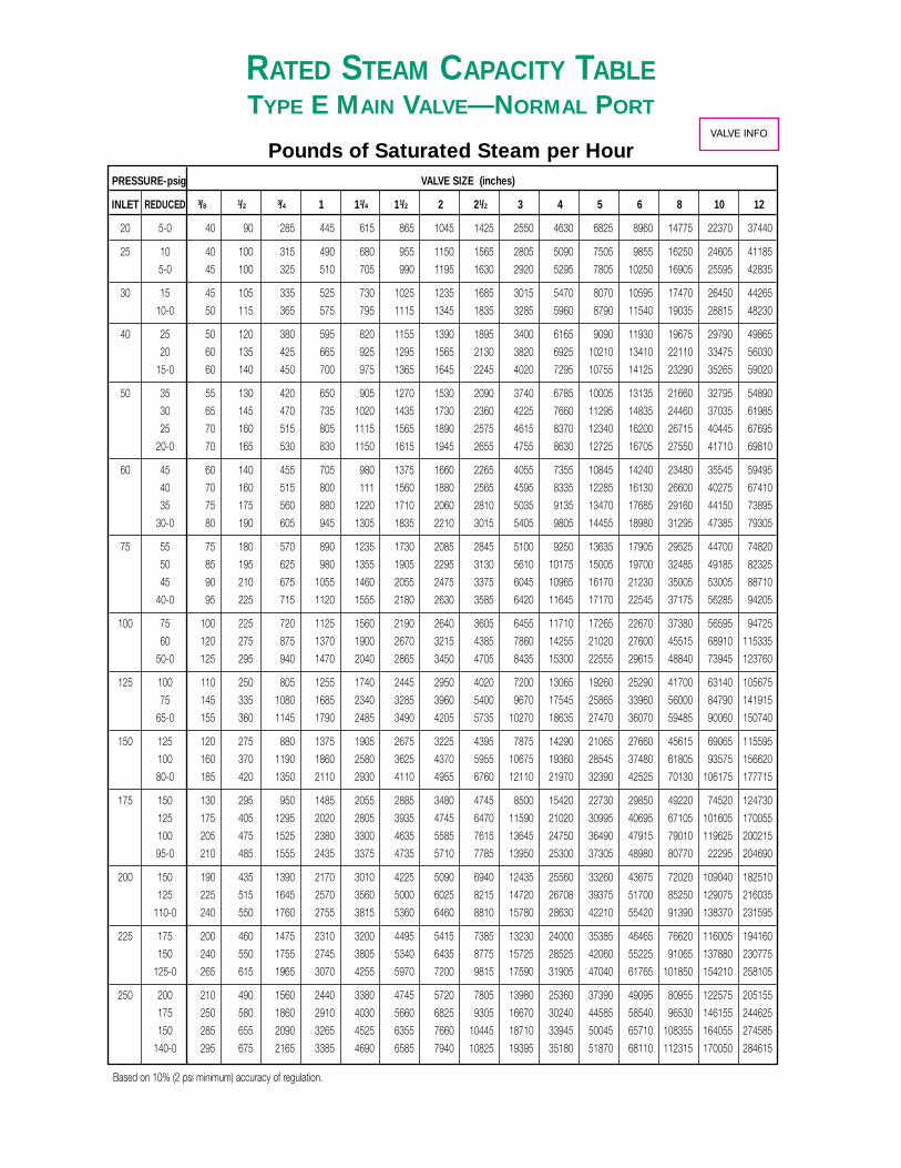
RATED STEAM CAPACITY TABLETYPE E MAIN VALVE—NORMAL PORT
Pounds of Saturated Steam per HourPRESSURE-psig VALVE SIZE (inches)
INLET REDUCED 3/8 1/2 3/4 1 11/4 11/2 2 21/2 3 4 5 6 8 10 12
20 5-0 40 90 285 445 615 865 1045 1425 2550 4630 6825 8960 14775 22370 37440
25 10 40 100 315 490 680 955 1150 1565 2805 5090 7505 9855 16250 24605 41185
5-0 45 100 325 510 705 990 1195 1630 2920 5295 7805 10250 16905 25595 42835
30 15 45 105 335 525 730 1025 1235 1685 3015 5470 8070 10595 17470 26450 44265
10-0 50 115 365 575 795 1115 1345 1835 3285 5960 8790 11540 19035 28815 48230
40 25 50 120 380 595 820 1155 1390 1895 3400 6165 9090 11930 19675 29790 49865
20 60 135 425 665 925 1295 1565 2130 3820 6925 10210 13410 22110 33475 56030
15-0 60 140 450 700 975 1365 1645 2245 4020 7295 10755 14125 23290 35265 59020
50 35 55 130 420 650 905 1270 1530 2090 3740 6785 10005 13135 21660 32795 54890
30 65 145 470 735 1020 1435 1730 2360 4225 7660 11295 14835 24460 37035 61985
25 70 160 515 805 1115 1565 1890 2575 4615 8370 12340 16200 26715 40445 67695
20-0 70 165 530 830 1150 1615 1945 2655 4755 8630 12725 16705 27550 41710 69810
60 45 60 140 455 705 980 1375 1660 2265 4055 7355 10845 14240 23480 35545 59495
40 70 160 515 800 111 1560 1880 2565 4595 8335 12285 16130 26600 40275 67410
35 75 175 560 880 1220 1710 2060 2810 5035 9135 13470 17685 29160 44150 73895
30-0 80 190 605 945 1305 1835 2210 3015 5405 9805 14455 18980 31295 47385 79305
75 55 75 180 570 890 1235 1730 2085 2845 5100 9250 13635 17905 29525 44700 74820
50 85 195 625 980 1355 1905 2295 3130 5610 10175 15005 19700 32485 49185 82325
45 90 210 675 1055 1460 2055 2475 3375 6045 10965 16170 21230 35005 53005 88710
40-0 95 225 715 1120 1555 2180 2630 3585 6420 11645 17170 22545 37175 56285 94205
100 75 100 225 720 1125 1560 2190 2640 3605 6455 11710 17265 22670 37380 56595 94725
60 120 275 875 1370 1900 2670 3215 4385 7860 14255 21020 27600 45515 68910 115335
50-0 125 295 940 1470 2040 2865 3450 4705 8435 15300 22555 29615 48840 73945 123760
125 100 110 250 805 1255 1740 2445 2950 4020 7200 13065 19260 25290 41700 63140 105675
75 145 335 1080 1685 2340 3285 3960 5400 9670 17545 25865 33960 56000 84790 141915
65-0 155 360 1145 1790 2485 3490 4205 5735 10270 18635 27470 36070 59485 90060 150740
150 125 120 275 880 1375 1905 2675 3225 4395 7875 14290 21065 27660 45615 69065 115595
100 160 370 1190 1860 2580 3625 4370 5955 10675 19360 28545 37480 61805 93575 156620
80-0 185 420 1350 2110 2930 4110 4955 6760 12110 21970 32390 42525 70130 106175 177715
175 150 130 295 950 1485 2055 2885 3480 4745 8500 15420 22730 29850 49220 74520 124730
125 175 405 1295 2020 2805 3935 4745 6470 11590 21020 30995 40695 67105 101605 170055
100 205 475 1525 2380 3300 4635 5585 7615 13645 24750 36490 47915 79010 119625 200215
95-0 210 485 1555 2435 3375 4735 5710 7785 13950 25300 37305 48980 80770 22295 204690
200 150 190 435 1390 2170 3010 4225 5090 6940 12435 25560 33260 43675 72020 109040 182510
125 225 515 1645 2570 3560 5000 6025 8215 14720 26708 39375 51700 85250 129075 216035
110-0 240 550 1760 2755 3815 5360 6460 8810 15780 28630 42210 55420 91390 138370 231595
225 175 200 460 1475 2310 3200 4495 5415 7385 13230 24000 35385 46465 76620 116005 194160
150 240 550 1755 2745 3805 5340 6435 8775 15725 28525 42060 55225 91065 137880 230775
125-0 265 615 1965 3070 4255 5970 7200 9815 17590 31905 47040 61765 101850 154210 258105
250 200 210 490 1560 2440 3380 4745 5720 7805 13980 25360 37390 49095 80955 122575 205155
175 250 580 1860 2910 4030 5660 6825 9305 16670 30240 44585 58540 96530 146155 244625
150 285 655 2090 3265 4525 6355 7660 10445 18710 33945 50045 65710 108355 164055 274585
140-0 295 675 2165 3385 4690 6585 7940 10825 19395 35180 51870 68110 112315 170050 284615
VALVE INFO

Based on 1 psi accuracy of regulation.
K-Factor is included in the above tabulations.
RATED STEAM CAPACITY TABLETYPE E2 MAIN VALVE
Pounds of Saturated Steam per HourPRESSURE-psig VALVE SIZE (inches)
INLET REDUCED 3/4 1 11/4 11/2 2 21/2 3 4 5 6 8 10 12
15 12 150 230 375 545 875 1350 1905 2840 4010 5060 9230 14850 22195
10 245 375 605 880 1415 2185 3085 4595 6490 8195 14945 24040 35930
8 295 455 735 1070 1715 2650 3740 5570 7870 9935 18120 29145 43560
5 345 530 860 1245 2000 3085 4360 6495 9170 11580 21110 33960 50760
2.5 375 575 930 1345 2160 3340 4715 7025 9925 12530 22850 36755 54935
12 9 145 220 355 515 825 1275 1800 2680 3785 4780 8715 14020 20955
7 230 355 570 830 1330 2060 2910 4330 6115 7720 14080 22650 33855
5 280 430 690 1005 1610 2490 3515 5235 7395 9340 17030 27390 40940
2 325 495 805 1165 1870 2890 4080 6075 8585 10835 19760 31785 47510
10 7 135 210 340 490 790 1220 1725 2570 3630 4580 8355 13440 20090
5 220 340 550 795 1275 1970 2780 4145 5855 7390 13475 21670 32395
2 280 435 705 1020 1635 2525 3565 5315 7505 9475 17280 27795 41545
1 “ HG VAC 310 480 775 1125 1805 2795 3945 5875 8295 10475 19095 30720 45915
9 6 135 205 330 480 775 1195 1685 2510 3550 4480 8170 13140 19645
4 215 330 535 775 1245 1925 2715 4045 5715 7215 13160 21165 31640
2 260 400 645 935 1500 2320 3275 4880 6890 8700 15865 25515 38140
2” HG VAC 300 460 745 1080 1730 2675 3780 5625 7950 10035 18300 29435 43995
8 5 130 200 325 470 755 1165 1645 2455 3465 4375 7980 12835 19185
3 210 325 520 755 1215 1875 2650 3950 5575 7040 12835 20650 30865
3.1“ HG VAC 285 440 710 1035 1660 2565 3620 5390 7615 9610 17530 28195 42145
7 4 125 195 315 460 735 1140 1605 2395 3380 4270 7785 12520 18715
2 205 315 510 735 1185 1830 2580 3845 5435 6860 12505 20120 30070
4.3’” HG VAC 275 420 680 985 1585 2450 3460 5150 7275 9185 16750 26945 40275
6 3 125 190 310 445 720 1110 1565 2330 3295 4160 7585 12200 18235
1 200 305 495 715 1150 1780 2510 3740 5285 6675 12170 19575 29255
5.5” HG VAC 260 405 650 945 1515 2340 3305 4925 6955 8780 16010 25755 38495
5 2 120 185 300 435 700 1080 1525 2270 3205 4045 7380 11870 17740
0 195 295 480 695 1120 1730 2440 3635 5135 6480 11820 19010 28415
6.7” HG VAC 250 380 615 895 1435 2215 3130 4660 6485 8310 15155 24380 36440
Size E2 Cv ∆P K
Valve Coefficient Nominal Factor3/4 7.6
1 11.7
11/4 18.9 3 0.635
11/2 27.4 4 0.785
2 44 5 0.855
21/2 68 6 0.895
3 96 7 0.915
4 143 8 0.928
5 202 9 0.935
6 255 10 0.937
8 465 11 0.938
10 748 12 0.940
12 1118 15 0.940
TYPE E2 MAIN VALVE ONLYUsed at such low pressure drops, a 1 psi deviation of reducedpressure at rated capacity is a significant portion of the totaldrop. It must be accounted for in calculations dealing with asubcritical flow condition.Also, because E2 valve opening, for 1 psi accuracy ofregulation, varies with the pressure drop, a regulation factor Kis inserted in the formula.
Cv= W
2.1 K √ ∆P’(P1 +P’2)
Where K = Factor from accompanying tableCv = Valve coefficientW = Flow, #/Hr. (saturated steam)∆P’ = ∆P nominal plus 1 psiP1 = Inlet pressure, psia (psi + 14.7)P2 = Reduced pressure, psia (psi + 14.7)P’2 = P2 nominal (set point value) minus 1 psi∆P = Pressure drop, psi
NOTE: When computing W for safety valve sizing, use K = 1.0
VALVE INFO

Based on 10% (2 psi minimum) accuracy of regulation.
RATED STEAM CAPACITY TABLETYPE E5 MAIN VALVE—FULL PORT
Pounds of Saturated Steam per HourPRESSURE-psig VALVE SIZE (inches)
INLET REDUCED 3/4 1 11/4 11/2 2 21/2 3 4 5 6 8 10 12
20 15 286 441 712 1033 1620 2525 3580 5992 9722 13189 25059 38361 6070810 389 599 967 1402 2201 3429 4862 8138 13205 17914 34036 52103 824535.4 451 694 1121 1626 2551 3976 5637 9435 15309 20768 39459 60405 95592
25 20 308 474 766 1110 1742 2714 3848 6440 10450 14176 26935 41232 6525115 420 647 1046 1516 2379 3707 5256 8796 14273 19363 36789 56318 8912410 496 764 1234 1788 2807 4373 6201 10378 16839 22844 43404 66444 1051498.3 516 794 1283 1860 2919 4548 6449 10794 17515 23760 45145 69109 109366
30 25 328 505 815 1182 1855 2890 4098 6859 11130 15099 28688 43916 6949820 450 692 1118 1621 2544 3965 5622 9409 15267 20711 39351 60239 9532915 533 821 1326 1922 3017 4700 6665 11154 18100 24554 46652 71417 113018
11.2 581 894 1445 2094 3287 5121 7262 12153 19721 26753 50831 77813 123140
40 35 365 561 907 1315 2063 3215 4558 7629 12379 16793 31906 48843 7729530 503 775 1251 1814 2847 4436 6290 10527 17082 23173 44029 67400 10666225 601 925 1494 2165 3398 5295 7507 12565 20388 27658 52550 80445 12730517 711 1094 1768 2563 4022 6267 8886 14872 24133 32738 62202 95221 150688
50 45 398 613 990 1435 2252 3509 4976 8327 13512 18331 34829 53317 8437440 551 849 1371 1988 3120 4862 6894 11538 18722 25397 48255 73870 11690135 661 1018 1644 2384 3741 5828 8264 13832 22444 30447 57849 88558 140144
22.8 841 1294 2091 3031 4757 7413 10511 17591 28544 38723 73574 112628 178236
75 70 471 726 1172 1699 2667 4155 5891 9860 15999 21704 41238 63128 9990265 657 1011 1634 2368 3717 5791 8211 13743 22300 30251 57477 87988 13924260 793 1220 1971 2857 4484 6987 9907 16581 26905 36499 69349 106161 168001
37.3 1166 1795 2899 4203 6596 10277 14572 24389 39574 53685 102002 156148 247106
100 95 535 823 1329 1927 3025 4713 6683 11184 18148 24620 46778 71608 11332190 748 1151 1859 2695 4230 6590 9345 15640 25378 34428 65412 100135 15846585 905 1393 2251 3263 5121 7979 11314 18935 30725 41682 79195 121234 191855
51.8 1491 2295 3707 5374 8434 13141 18633 31186 50603 68648 130431 199667 315977
125 120 591 910 1470 2131 3345 5212 7390 12368 20069 27225 51727 79185 125312115 828 1275 2060 2987 4687 7303 10355 17331 28121 38149 72484 110960 175596110 1005 1547 2500 3624 5687 8861 12564 21028 34120 46287 87946 134630 21305590 1476 2272 3671 5322 8352 13013 18451 30882 50110 67979 129159 197720 312896
66.3 1816 1751 191 7874 12019 19297 27890 43660 67921 96226 160923 261002 354004
150 145 643 990 1598 2317 3637 5667 8035 13448 21820 29601 56243 86098 136251140 902 1389 2243 3252 5103 7952 11275 18871 30620 41539 78924 120819 191198135 1096 1687 2726 3951 6201 9662 13700 22930 37207 50475 95902 146809 232328110 1717 2644 4270 6191 9716 15138 21465 35925 58293 79080 150252 230010 36399480.8 2140 2075 191 8545 13051 20965 30308 47454 73834 104610 174955 283770 384891
175 170 691 1063 1717 2490 3907 6088 8632 14447 23442 31801 60422 92495 146375165 970 1493 2412 3497 5488 8552 12125 20294 32930 44672 84877 129932 205619160 1180 1817 2934 4254 6676 10402 14750 24686 40057 54340 103247 158053 250121125 2048 3153 5094 7384 11589 18057 25603 42851 69532 94327 179221 274356 43417295.3 2465 2400 191 9165 14007 22508 32545 50966 79306 112368 187941 304841 413476
200 195 735 1132 1828 2651 4160 6481 9190 15381 24958 33858 64330 98478 155843185 1258 1937 3129 4537 7119 11093 15729 26325 42716 57949 110102 168548 266729150 2198 3384 5467 7925 12437 19379 27477 45989 74623 101233 192342 294443 465960
109.8 2790 4296 6939 10060 15787 24598 34878 58375 94721 128498 244146 373745 591458
250 245 817 1258 2032 2946 4624 7205 10215 17098 27743 37636 71508 109467 173233235 1402 2158 3486 5054 7932 12359 17524 29330 47592 64563 122670 187786 297174200 2471 3804 6145 8908 13980 21784 30887 51695 83883 113795 216210 330979 523780
138.8 3440 5296 8555 12402 19463 30327 43001 71969 116780 158423 301004 460784 729198
VALVE INFO
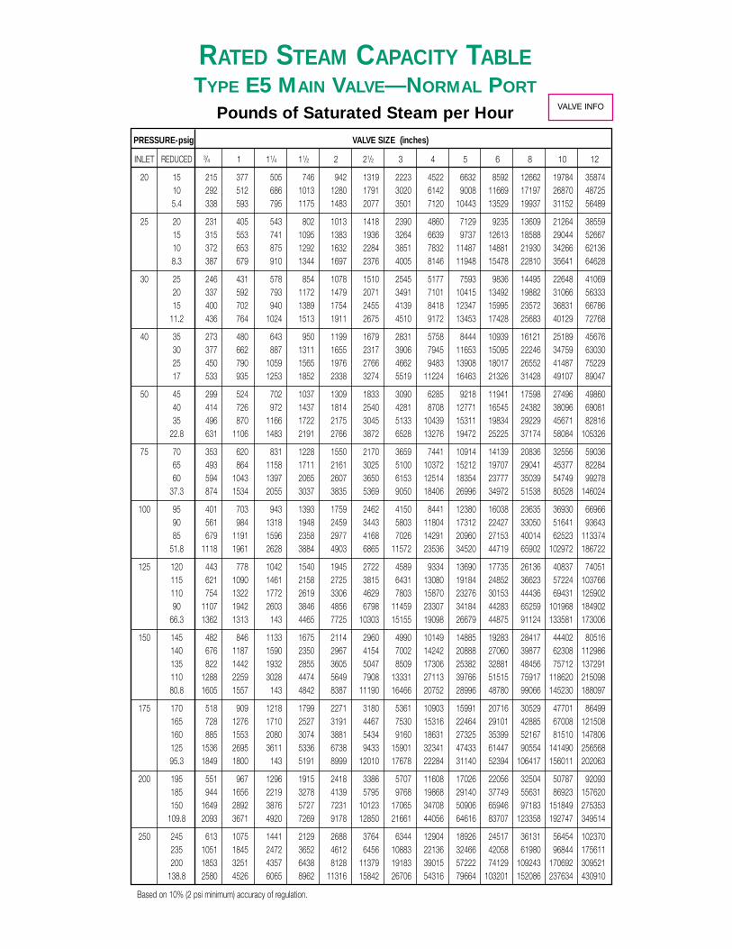
Based on 10% (2 psi minimum) accuracy of regulation.
RATED STEAM CAPACITY TABLETYPE E5 MAIN VALVE—NORMAL PORT
Pounds of Saturated Steam per HourPRESSURE-psig VALVE SIZE (inches)
INLET REDUCED 3/4 1 11/4 11/2 2 21/2 3 4 5 6 8 10 12
20 15 215 377 505 746 942 1319 2223 4522 6632 8592 12662 19784 3587410 292 512 686 1013 1280 1791 3020 6142 9008 11669 17197 26870 487255.4 338 593 795 1175 1483 2077 3501 7120 10443 13529 19937 31152 56489
25 20 231 405 543 802 1013 1418 2390 4860 7129 9235 13609 21264 3855915 315 553 741 1095 1383 1936 3264 6639 9737 12613 18588 29044 5266710 372 653 875 1292 1632 2284 3851 7832 11487 14881 21930 34266 621368.3 387 679 910 1344 1697 2376 4005 8146 11948 15478 22810 35641 64628
30 25 246 431 578 854 1078 1510 2545 5177 7593 9836 14495 22648 4106920 337 592 793 1172 1479 2071 3491 7101 10415 13492 19882 31066 5633315 400 702 940 1389 1754 2455 4139 8418 12347 15995 23572 36831 66786
11.2 436 764 1024 1513 1911 2675 4510 9172 13453 17428 25683 40129 72768
40 35 273 480 643 950 1199 1679 2831 5758 8444 10939 16121 25189 4567630 377 662 887 1311 1655 2317 3906 7945 11653 15095 22246 34759 6303025 450 790 1059 1565 1976 2766 4662 9483 13908 18017 26552 41487 7522917 533 935 1253 1852 2338 3274 5519 11224 16463 21326 31428 49107 89047
50 45 299 524 702 1037 1309 1833 3090 6285 9218 11941 17598 27496 4986040 414 726 972 1437 1814 2540 4281 8708 12771 16545 24382 38096 6908135 496 870 1166 1722 2175 3045 5133 10439 15311 19834 29229 45671 82816
22.8 631 1106 1483 2191 2766 3872 6528 13276 19472 25225 37174 58084 105326
75 70 353 620 831 1228 1550 2170 3659 7441 10914 14139 20836 32556 5903665 493 864 1158 1711 2161 3025 5100 10372 15212 19707 29041 45377 8228460 594 1043 1397 2065 2607 3650 6153 12514 18354 23777 35039 54749 99278
37.3 874 1534 2055 3037 3835 5369 9050 18406 26996 34972 51538 80528 146024
100 95 401 703 943 1393 1759 2462 4150 8441 12380 16038 23635 36930 6696690 561 984 1318 1948 2459 3443 5803 11804 17312 22427 33050 51641 9364385 679 1191 1596 2358 2977 4168 7026 14291 20960 27153 40014 62523 113374
51.8 1118 1961 2628 3884 4903 6865 11572 23536 34520 44719 65902 102972 186722
125 120 443 778 1042 1540 1945 2722 4589 9334 13690 17735 26136 40837 74051115 621 1090 1461 2158 2725 3815 6431 13080 19184 24852 36623 57224 103766110 754 1322 1772 2619 3306 4629 7803 15870 23276 30153 44436 69431 12590290 1107 1942 2603 3846 4856 6798 11459 23307 34184 44283 65259 101968 184902
66.3 1362 1313 143 4465 7725 10303 15155 19098 26679 44875 91124 133581 173006
150 145 482 846 1133 1675 2114 2960 4990 10149 14885 19283 28417 44402 80516140 676 1187 1590 2350 2967 4154 7002 14242 20888 27060 39877 62308 112986135 822 1442 1932 2855 3605 5047 8509 17306 25382 32881 48456 75712 137291110 1288 2259 3028 4474 5649 7908 13331 27113 39766 51515 75917 118620 21509880.8 1605 1557 143 4842 8387 11190 16466 20752 28996 48780 99066 145230 188097
175 170 518 909 1218 1799 2271 3180 5361 10903 15991 20716 30529 47701 86499165 728 1276 1710 2527 3191 4467 7530 15316 22464 29101 42885 67008 121508160 885 1553 2080 3074 3881 5434 9160 18631 27325 35399 52167 81510 147806125 1536 2695 3611 5336 6738 9433 15901 32341 47433 61447 90554 141490 25656895.3 1849 1800 143 5191 8999 12010 17678 22284 31140 52394 106417 156011 202063
200 195 551 967 1296 1915 2418 3386 5707 11608 17026 22056 32504 50787 92093185 944 1656 2219 3278 4139 5795 9768 19868 29140 37749 55631 86923 157620150 1649 2892 3876 5727 7231 10123 17065 34708 50906 65946 97183 151849 275353
109.8 2093 3671 4920 7269 9178 12850 21661 44056 64616 83707 123358 192747 349514
250 245 613 1075 1441 2129 2688 3764 6344 12904 18926 24517 36131 56454 102370235 1051 1845 2472 3652 4612 6456 10883 22136 32466 42058 61980 96844 175611200 1853 3251 4357 6438 8128 11379 19183 39015 57222 74129 109243 170692 309521
138.8 2580 4526 6065 8962 11316 15842 26706 54316 79664 103201 152086 237634 430910
VALVE INFO
Based on 10% (2 psi minimum) accuracy of regulation.
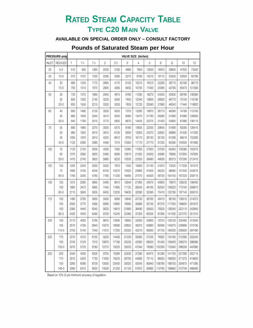
RATED STEAM CAPACITY TABLETYPE C20 MAIN VALVE
AVAILABLE ON SPECIAL ORDER ONLY – CONSULT FACTORY
Pounds of Saturated Steam per HourPRESSURE-psig VALVE SIZE (inches)
INLET REDUCED 1 11/4 11/2 2 21/2 3 4 5 6 8 10 12
25 5-0 510 950 1360 2035 3190 4685 7805 12625 16970 29600 47520 73520
30 10-0 575 1070 1530 2295 3595 5275 8790 14215 19110 33325 53505 82780
40 20 665 1245 1775 2665 4175 6125 10210 16515 22200 38715 62160 96170
15-0 700 1310 1870 2805 4395 6455 10755 17400 23385 40780 65475 101300
50 30 735 1375 1965 2945 4615 6780 11295 18270 24555 42830 68760 106385
25 805 1500 2145 3220 5040 7405 12340 19955 26820 46775 75100 116190
20-0 830 1550 2215 3320 5200 7635 12725 20580 27660 48240 77445 119820
60 40 800 1495 2135 3205 5020 7370 12285 19870 26710 46580 74780 115700
35 880 1640 2340 3515 5505 8080 13470 21785 29280 51060 81980 126830
30-0 945 1760 2515 3770 5905 8670 14455 23375 31420 54800 87980 136115
75 55 890 1660 2370 3555 5575 8180 13635 22055 29645 51695 83000 128410
50 980 1825 2610 3915 6130 9000 15005 24270 32620 56885 91330 141300
45 1055 1970 2810 4220 6610 9700 16170 26150 35150 61295 98415 152260
40-0 1120 2090 2985 4480 7015 10300 17170 27770 37325 65090 104505 161685
100 75 1125 2100 3000 4505 7055 10360 17265 27920 37530 65450 105080 162575
60 1370 2560 3655 5485 8590 12610 21020 34000 45695 79695 127950 197955
50-0 1470 2745 3925 5885 9220 13535 22555 36480 49035 85515 137295 212415
125 100 1255 2345 3350 5025 7870 1555 19260 31150 41870 73020 117230 181375
75 1685 3150 4500 6745 10570 15520 25865 41835 56225 98060 157435 243575
65-0 1790 3345 4780 7165 11230 16485 27470 44435 59720 104155 167220 258715
150 125 1375 2565 3665 5495 8610 12640 21065 34075 45800 79875 128235 198400
100 1860 3475 4965 7445 11665 17125 28545 46165 62050 108220 173745 268810
80-0 2110 3945 5635 8450 13235 19435 32390 52385 70410 122795 197145 305015
175 150 1485 2765 3955 5930 9290 13640 22730 36765 49415 86185 138310 214075
125 2020 3775 5390 8085 12665 18595 30995 50130 67375 117505 188655 291875
100 2380 4440 6345 9520 14915 21895 36490 59020 79325 138345 222110 343640
95-0 2435 4540 6490 9730 15245 22385 37305 60335 81095 141435 227070 351310
200 150 2170 4050 5785 8675 13595 19955 33260 53800 72310 126105 202465 313245
125 2570 4795 6845 10270 16090 23625 39375 63680 85595 149275 239660 370790
110-0 2755 5140 7340 11010 17250 25325 42210 68265 91755 160025 256920 397490
225 175 2310 4310 6155 9230 14460 21230 35385 57235 76925 134160 215395 333245
150 2745 5120 7315 10970 17190 25235 42060 68025 91430 159455 256010 396080
125-0 3070 5725 8180 12270 19225 28225 47040 76080 102260 178340 286330 442995
250 200 2440 4550 6505 9755 15280 22435 37390 60475 81280 141755 227590 352115
175 2910 5425 7755 11630 18220 26750 44585 72110 96920 169025 271375 419855
150 3265 6090 8705 13055 20455 30025 50045 80940 108790 189730 304615 471280
140-0 3385 6315 9020 13530 21200 31125 51870 83895 112765 196660 315740 488495
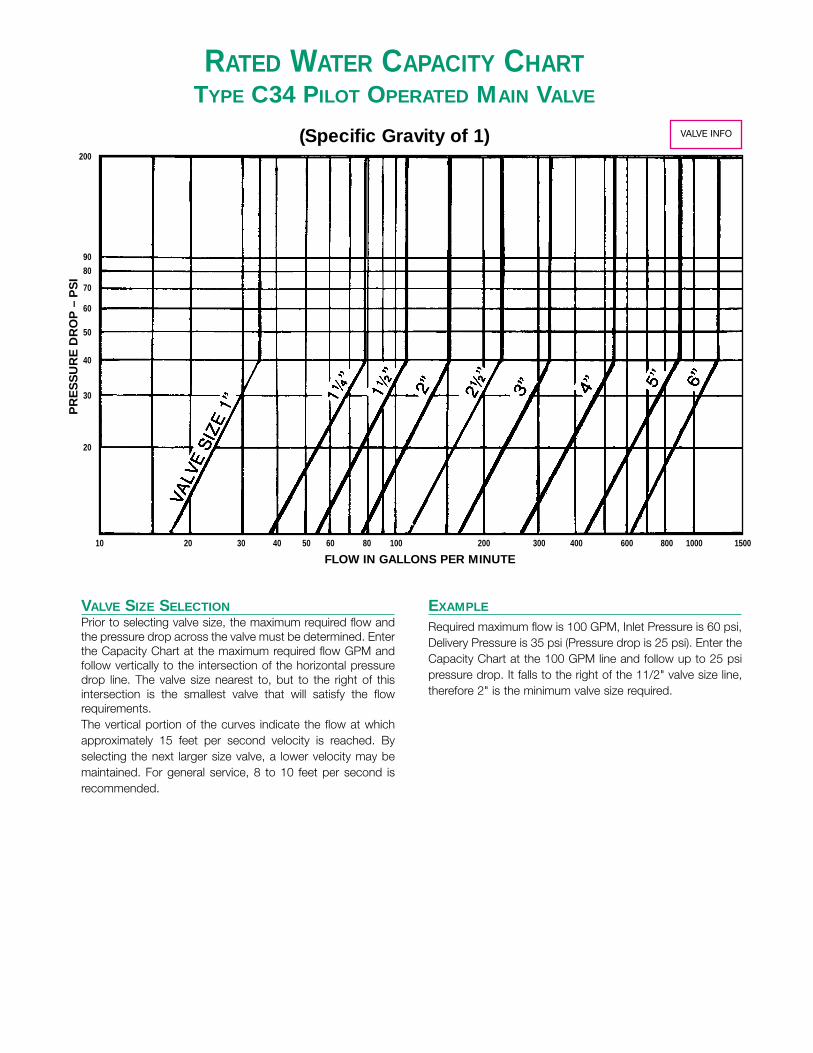
RATED WATER CAPACITY CHARTTYPE C34 PILOT OPERATED MAIN VALVE
(Specific Gravity of 1)
EXAMPLE
Required maximum flow is 100 GPM, Inlet Pressure is 60 psi,Delivery Pressure is 35 psi (Pressure drop is 25 psi). Enter theCapacity Chart at the 100 GPM line and follow up to 25 psipressure drop. It falls to the right of the 11/2" valve size line,therefore 2" is the minimum valve size required.
VALVE SIZE SELECTIONPrior to selecting valve size, the maximum required flow andthe pressure drop across the valve must be determined. Enterthe Capacity Chart at the maximum required flow GPM andfollow vertically to the intersection of the horizontal pressuredrop line. The valve size nearest to, but to the right of thisintersection is the smallest valve that will satisfy the flowrequirements.The vertical portion of the curves indicate the flow at whichapproximately 15 feet per second velocity is reached. Byselecting the next larger size valve, a lower velocity may bemaintained. For general service, 8 to 10 feet per second isrecommended.
10
20
30
40
50
60
70
80
90
200
20 30 40 50 60 80 100 200 300 400 600 800 1000 1500
FLOW IN GALLONS PER MINUTE
PR
ES
SU
RE
DR
OP
– P
SI
VALVE INFO

RATED WATER CAPACITY CHARTTYPE N6 DIFFERENTIAL PRESSURE VALVE
(Specific Gravity of 1)
RATED WATER CAPACITY TABLETYPE D34 VALVE
Water in GPMPRESSURE VALVE SIZE (inches)
DROP–psig 1 11/4 11/2 2 21/2 3 4 5 6
5 7.4 17 23 32 48 71 116 188 263
10 10 24 33 45 68 101 164 266 373
15 13 29 40 55 84 124 201 325 457
20 15 33 47 64 97 143 233 376 528
30 18 41 51 79 118 175 285 460 646
50 23 53 74 102 153 226 368 594 834
75 29 65 90 125 187 277 450 727 1022
100 33 75 104 144 216 320 520 840 1180
125 37 84 116 161 241 358 581 939 1320
150 40 92 127 176 265 392 637 1029 1445
175 44 100 138 190 285 423 688 1111 1560
500400300250200150100908070605040302015
10
20
30
40
50
60
70
80
90
1003/4" 1" 11/4" 11/2" 2"
21/2"
FLOW IN GALLONS PER MINUTE
PR
ES
SU
RE
DR
OP
– P
SI
VALVE INFO
VALVE INFO

5 10 15 20 25
SIZING D36 WATER PRESSURE REDUCING VALVE
EXAMPLE
SPECIFIED CONDITIONSInitial Pressure = 100 PSIG
Reduced No Flow Pressure = 50 PSIG (lock-up pressure)Capacity Required = 30 GPM
Allowable Droop = 10-15 PSIG
1. Enter Capacities vs. Droop Chart, below, at 30 GPM. Moveup until you intersect a curve line (possibly more than onecurve). e.g. points (a), (b)…etc.
The lowest point indicates the minimum size valve required(3/4") at a droop of approximately 16 psi.
2. Enter Flow vs. Velocity Chart (left) at 30 GPM and move upuntil you reach the 3/4" pipe size curve. Move downward andnote that the velocity is approximately 18.5 ft./sec., which isunacceptably high.
At the point of intersection of 30 GPM with the next valvecurve (1"), the velocity will be approximately 11 ft./sec.,which is closer to the recommended value.
Referring back to the Capacities vs. Droop Chart, you willfind that the droop for a 1" valve is only 11 psig, which is alsomore acceptable.
SELECT A 1" TYPE D36
NOTE: The capacities shown in the Capacities vs. DroopChart are based on a difference of 50 psig or more betweenthe initial pressure and the regulator lock-up pressure.Where this difference is less than 50 psig, deduct 20% fromthe capacity obtained.
GENERAL CONSIDERATIONSWhen sizing a water valve, the following points should beconsidered:
(a) The recommended velocity in the pipe (8-10 ft./sec.)
(b) The droop which is the fall-off pressure below the no flowpressure setting.
a
10
20
15
10
5
0
20 30 40 50 60 70 80 90 100 110 120 130 140 150 160 170
b
CAPACITIES VS. DROOP CHART
FLOW VS. VELOCITY CHART(Specific Gravity of 1)
GALLONS PER MINUTE
VELOCITY FT./SEC.
DR
OO
P P
SIG
3/4" 11/4" 11/2" 2"1"1/2"
0
2
4
6
810
20
40
60
80100
200
400500
2"
11/2"
11/4"
1"
3/4"
1/2"
SCHEDULE 40 PIPE SIZE
FLO
W I
N G
ALL
ON
S P
ER
MIN
UT
E
VALVE INFO

VALVE SIZE 1/2" 3/4" 1" 11/4" 11/2" 2”
PSI CV 2.2 3.3 4.9 5.0 10.1 10.8
IN OUT S A W S A W S A W S A W S A W S A W
10 5 41 14 3 59 20 4.2 80 27 5.7 91 30 6.5 105 35 7.4 120 40 8.5
20 10 68 23 4.2 97 33 6.0 130 44 3.1 150 50 9.2 170 57 10 230 77 14
30 10 100 35 5.9 145 50 8.5 195 67 11 220 76 13 250 87 15 290 100 17
40 87 29 4.2 125 42 6.0 170 57 8.1 190 64 9 250 85 12 265 89 13
50 130 43 5.9 185 63 8.5 250 84 11 285 95 13 375 125 17 395 130 18
75 200 72 8.8 290 105 13 390 140 17 440 160 19 580 210 25 610 220 27
100 255 98 11 370 140 16 495 190 21 565 215 24 740 285 32 780 295 33
125 30 315 105 13 450 175 19 605 240 25 690 270 28 900 355 37 950 375 39
150 370 145 15 530 210 21 715 285 28 810 325 32 1065 425 42 1120 445 44
175 425 170 16 615 245 23 825 330 31 935 375 35 1230 495 46 1290 520 48
200 480 195 17 695 280 25 930 375 33 1060 430 38 1390 560 50 1460 590 52
250 595 240 20 855 350 28 1150 470 38 1305 535 43 1710 700 56 1800 735 60
60 115 38 4.6 165 55 6.6 250 85 10 260 87 10 355 120 14 395 130 16
75 190 63 7.2 275 92 10 420 140 16 430 145 17 585 195 23 655 220 25
85 230 77 8.5 335 110 12 510 170 19 525 175 20 715 240 27 800 270 30
100 280 96 10 410 140 15 625 215 23 645 220 23 875 300 32 1000 335 35
125 50 340 125 12 500 185 18 760 280 28 785 290 29 1070 390 39 1190 435 43
150 405 155 14 590 225 21 895 340 32 925 350 33 1260 480 45 1400 535 50
175 465 180 16 675 265 23 1030 400 36 1065 415 37 1450 565 50 1620 630 56
200 525 205 18 765 305 26 1170 460 39 1205 475 40 1640 650 55 1830 720 61
250 650 260 20 945 380 30 1440 580 45 1485 595 47 2020 815 65 2260 905 71
85 130 44 4.6 190 64 6.6 290 98 10 300 100 10 410 140 14 455 155 16
100 215 72 7.2 315 105 10 480 160 16 495 165 17 675 225 23 750 250 25
125 325 110 10 470 160 15 720 240 23 740 250 23 1010 340 32 1130 380 35
150 75 405 140 12 590 205 18 895 310 28 925 320 29 1260 440 39 1400 485 43
175 465 170 14 675 245 21 1030 375 32 1065 390 33 1450 530 45 1620 590 50
200 525 200 16 765 290 23 1170 440 36 1205 455 37 1640 620 50 1830 685 56
225 585 225 18 855 330 26 1300 500 39 1345 515 40 1830 705 55 2040 785 61
250 650 250 19 945 370 28 1440 560 42 1485 580 44 2020 790 60 2250 880 66
110 190 65 6 310 105 9 380 125 12 400 135 12 465 155 14 515 170 16
125 310 105 9 500 170 15 620 210 19 655 220 20 755 255 23 840 280 25
150 460 155 13 745 250 21 920 310 26 970 325 28 1120 375 32 1250 415 35
200 100 675 235 19 1095 385 30 1350 475 37 1430 500 39 1650 575 45 1830 640 50
225 755 275 21 1220 445 34 1510 550 41 1590 580 44 1840 665 50 2040 740 56
250 830 310 23 1350 505 37 1670 620 45 1760 655 48 2030 760 55 2250 840 61
135 210 70 5.9 340 115 9.5 420 140 12 440 150 12
150 340 115 9.3 550 185 15 680 225 19 715 240 20
175 500 165 13 810 270 21 995 335 26 1050 350 28
200 125 635 210 16 1030 345 26 1270 425 32 1340 450 34
225 755 255 19 1230 410 30 1510 505 37 1500 535 39
250 830 295 21 1350 475 34 1670 585 41 1760 615 44
160 315 105 8.3 510 170 13 630 210 17 665 225 17
175 425 145 11 690 230 18 855 285 22 900 300 23
200 140 580 195 14 940 315 23 1160 390 29 1220 410 30
225 710 240 17 1150 385 28 1420 475 34 1500 505 36
250 835 280 19 1350 455 31 1670 560 39 1760 590 41
S — Steam (#/hr.)A — Air (SCFM)W — Water (GPM)
RATED STEAM, AIR AND WATER CAPACITY TABLETYPE D50 DIRECT ACTING PRESSURE REGULATOR VALVE INFO
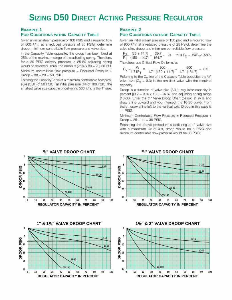
SIZING D50 DIRECT ACTING PRESSURE REGULATOR
EXAMPLE 2FOR CONDITIONS OUTSIDE CAPACITY TABLE
Given an initial steam pressure of 150 psig and a required flowof 900 #/hr. at a reduced pressure of 25 PSIG, determine thevalve size, droop and minimum controllable flow pressure.
P2= (25 + 14.7) = 39.7 = .24 thus P2 = .24P1< .58P1P1 (150 + 14.7) 164.7Therefore, use Critical Flow Cv formula:
Cv = W = 900 = 900 = 3.21.71P1 1.71 (150 + 14.7) 1.71 (164.7)
Referring to the Cv line of the Capacity Table opposite, the 3/4"valve size (Cv = 3.3) is the smallest valve with the requiredcapacity.Droop is a function of valve size (3/4"), regulator capacity inpercent [(3.2 ÷ 3.3) x 100 = 97%] and adjusting spring range(10-30). Enter the 3/4" Valve Droop Chart (below) at 97% anddraw a line upward until you intersect the 10-30 curve. Fromthere , draw a line left to the vertical axis. Droop in this case is11 PSIG.Minimum Controllable Flow Pressure = Reduced Pressure +Droop = 25 + 11 = 36 PSIGRepeating the above procedure substituting a 1" valve sizewith a maximum Cv of 4.9, droop would be 8 PSIG andminimum controllable flow pressure would be 33 PSIG.
EXAMPLE 1FOR CONDITIONS WITHIN CAPACITY TABLE
Given an initial steam pressure of 100 PSIG and a required flowof 500 #/hr. at a reduced pressure of 30 PSIG, determinedroop, minimum controllable flow pressure and valve size.In the Capacity Table opposite, the droop has been fixed at25% of the maximum range of the adjusting spring. Therefore,for a 30 PSIG delivery pressure, a 25-80 adjusting springwould be selected. Thus, the droop is (25% x 80 = 20) 20 PSI.Minimum controllable flow pressure = Reduced Pressure +Droop = 30 + 20 = 50 PSIGEntering the Capacity Table at a minimum controllable flow pres-sure (OUT) of 50 PSIG, an initial pressure (IN) of 100 PSIG, thesmallest valve size capable of delivering 500 #/hr. is the 1" size.
1/2" VALVE DROOP CHART
35
25
15
10
5
0
DR
OO
P, P
SIG
REGULATOR CAPACITY IN PERCENT0 10 20 30 40 50 60 70 80 90 100
75-140
25-80
10-30
3-15
1" & 11/4" VALVE DROOP CHART
35
25
15
10
5
0
DR
OO
P, P
SIG
REGULATOR CAPACITY IN PERCENT0 10 20 30 40 50 60 70 80 90 100
75-140
25-80
10-30
3-15
3/4" VALVE DROOP CHART
35
25
15
10
5
0
DR
OO
P, P
SIG
REGULATOR CAPACITY IN PERCENT0 10 20 30 40 50 60 70 80 90 100
75-140
25-80
10-30
3-15
11/2" & 2" VALVE DROOP CHART
35
25
15
10
5
0
DR
OO
P, P
SIG
REGULATOR CAPACITY IN PERCENT0 10 20 30 40 50 60 70 80 90 100
30-100
10-40
3-15