rehabilitating high-temperature aeration piping at a...
TRANSCRIPT

Paper B-4-02 - 1
North American Society for Trenchless Technology (NASTT) No-Dig Show 2012
______________________________________________________
Nashville, TN March 11-15, 2012
Paper B-4-02
Rehabilitating High-Temperature Aeration Piping at a Wastewater Treatment Plant – Challenges Faced and Lessons Learned Duane Larson, P.E1, Jennifer Glynn, P.E.2, and Patricia Butler, P.E.3
1 General Services Director, Encina Wastewater Authority, Carlsbad, CA 2 Senior Project Manager, RMC Water and Environment, Walnut Creek, CA 3 Senior Project Manager, RMC Water and Environment, Irvine, CA ABSTRACT: The Encina Wastewater Authority (EWA) is a Joint Powers Authority serving the cities of Carlsbad, Vista, and Encinitas, as well as Vallecitos Water District, Buena Sanitation District, and Leucadia Wastewater District. EWA provides wastewater treatment to 300,000 residents in northwestern San Diego County. The EWA treatment plant is equipped with blowers to provide air for process aeration and channel mixing. The air is conveyed from the blowers to these processes via a 1979 vintage 42-inch mortar coated, epoxy lined carbon steel pipe with cloth reinforced neoprene gaskets. Due to the temperature rise of the blowers during compression, the process air reaches a peak operating temperature of 250 degrees F and cools as it is travels through the 500 feet of delivery pipe. The aeration pipe was corroded and leaking. Limited inspection of the pipe was performed in the past because of difficulties in taking the pipe out of service. However, significant air bubbling had been seen at the paved surface during rain events. Loss of air through this pipe has resulted in energy inefficiency. There was also a concern that corrosion of this pipe may cause pipe collapse and/or impact the volume of air delivered to the aeration basins; thereby affecting future wastewater effluent quality. A preliminary evaluation was completed in 2006 and recommended that the buried 42-inch aeration piping be replaced with aboveground pipe. The estimated cost was $3.7M. Because of the recommended project’s high cost, difficult pipe construction, and impact on plant operations; trenchless rehabilitation was identified as an alternative approach. This paper is a case study discussing the options evaluated and the challenges associated with rehabilitation design of a large diameter high temperature aeration pipe as well as lessons learned during construction of this project. 1. BACKGROUND The EWA treatment plant provides wastewater treatment of approximately 40 Million Gallons per Day (MGD).
The facility is equipped with two sets of three blowers each to provide air for process and mixing/agitation
purposes. The aeration system is used for the following:
• Aeration system process air supply
• Aerated grit chambers

Paper B-4-02 - 2
Figure 1. Air bubbles escaping from the pipe
The agitation air system is used in the following channels to maintain solids in suspension:
• bar screen influent channels
• primary influent channels at primary sedimentation basins
• primary effluent channels at aeration basins
• mixed liquor channels
Air Piping
The aeration piping from the blowers to the point of service was corroded and leaking. Loss of air through this piping was resulting in energy inefficiency. There was also concern that corrosion would impact the air piping to the point that it would become inadequate to deliver the process air required at the aeration basins.
The existing aeration piping system is a 42-inch diameter concrete mortar coated and epoxy lined carbon steel pipe, some sections with cloth reinforced neoprene gaskets and other with cloth reinforced neoprene gaskets. Ancillary system piping includes reaches of 18-, 30-, and 36-inch diameter steel piping. The purpose of the 42-inch pipeline is to convey air from a series of aeration blowers in the facility’s blower room to four aeration basins approximately 500 feet downstream. Due to the temperature rise of the blowers, the air conveyed is a much higher temperature than ambient and cools as it is conveyed through the pipe. Approximately 235 feet downstream from the blower building, the 42-inch pipe transitions from below ground to above ground and makes a 40 foot (horizontal length) aerial crossing of a flood control channel. It then transitions back to a buried system for an additional 120 feet until it terminates at the aeration basins.
The piping from the blower building to the flood control bridge was installed in 1980. The piping between the flood control channel bridge and the aeration basins was installed in 1979. Since the system was installed, indications of air leakage, evidenced in the form of air bubbles on the pavement during rain events, have been observed as shown in Figure 1.
In 2004, the 42-inch tee, 42-inch by 30-inch reducer and 30-inch header at the southern end of the alignment and closest to the aeration basins were excavated and partially exposed to allow for a corrosion engineering evaluation of the pipe. The corrosion study concluded that extensive pitting was present on all exposed pipe. The cathodic protection wires at the tee were discovered to be broken. As a result of this investigation, the 42-inch tee was rehabilitated with Belzona, a polymeric repair and maintenance product. A buried section of pipe was replaced with an elbow up to a new above ground stainless steel main header to Aeration Basin Nos. 1 and 2. Buried stainless steel piping to Aeration Basin Nos. 3 and 4 was installed and encased in 1989. The stainless steel components were assumed to be in good condition and were out of the scope of the project.
A preliminary evaluation completed by others in 2006 recommended that the buried 42-inch aeration piping from the Blower building to the original 42-inch by 30-inch tee adjacent to the aeration basins be replaced with an aboveground pipe. The planning level cost estimate for this approach was approximately $2.7M. Location of the aboveground piping would have included several overhead bridges and would have been difficult to locate and maneuver around on the congested plant site. Because of the high cost as well as the difficulties associated with the pipe’s construction and its impact on plant operations; rehabilitation, partial replacement, or a combination of techniques has been identified as an alternative approach to the 2006 recommendation. This paper summarizes that revised approach, subsequent findings, and lessons learned during construction of this project.

Paper B-4-02 - 3
2. REHABILITATION DESIGN CRITERIA
Existing Condition of the Aeration Piping
Evidence of air leakage from the existing aeration piping has been present for over fifteen years. The interior of the pipe was inspected approximately ten years ago using a remote operated video camera. The images captured did not reveal obvious damage to the interior. Over time, EWA has excavated to expose limited stretches of the pipeline exterior in conjunction with replacement of portions of the piping system or for the purpose of inspection. Exposed exterior piping has been characterized by significant corrosion and in some locations pitting. More extensive inspection of the pipeline has been limited to avoid disturbing the existing piping and impeding air flow to secondary treatment. Based on the significant corrosion observed in the piping, it is assumed that the structural integrity of the existing pipe is reduced. Therefore, this project will require a rehabilitation method that will provide a structural integrity to carry pipeline and traffic loads.
Air Temperature
The aeration blowers discharge air to the 42-inch pipeline at elevated temperatures as shown in Table 1.
Table 1. Blower Discharge Temperatures
Blower Designation Temperature, degrees F.
Ambient (1)
Temp Rise (2)
Blower Discharge
Agitation Air Blower #1 B4009 60-100 79 – 83 139-183
Agitation Air Blower #2 B4010 60-100 79 – 83 139-183
Agitation Air Blower #3 B4011 60-100 106 – 120 166-220
Aeration Air Blower #1 B4006 60-100 132 – 160 192-260
Aeration Air Blower #2 B4007 60-100 113 – 125 173-225
Aeration Air Blower #3 B4008 60-100 113 – 125 173-225
(1) Historical ambient air temperature range in Carlsbad, CA, 60 deg F to 100 deg F (2) Temperature rise increases as blowers age and when blower is operated at reduced output. (Source: Tim
Rizor, McKenna Engineering, Inc, representing Roots, and Gardner Denver/Lamson, requested the information from blower manufacturing facilities.)
The design temperature of the aeration air piping system is determined by the estimated blower discharge temperature. Factors determining the actual temperature in the rehabilitated portion of the piping include the ambient temperature at the time of operation, the temperature rise of the blower, the discharge temperature of other blowers operating in parallel, and the amount of cooling taking place in the pipeline as air is conveyed away from the blowers. As shown in Table 1, the maximum discharge temperature of all blowers except for the oldest blower (B4006) is below 225 degrees F. Taking into account a factor of safety, all rehabilitation methods identified in this memo are suitable for temperatures of 250 degrees F and below. It is important to note that, under many operational modes including winter time operation and operation in parallel with other lower discharge temperature blower systems, plus with consideration of air cooling in the pipeline, actual air temperature would most likely be below the 250 degree F design criteria.
Air Pressure
The maximum pressure in this pipeline is 8 psi. Lining rehabilitation alternatives identified in this memo are appropriate for system design pressures of 10 psi and above.
Air Flow Volume
The maximum existing air piping air flow requirement is 36,000 cfm, which includes all aeration and agitation air for the system. RMC developed a model of the existing air system to determine the impact of reducing the air piping diameter from 42-inch to 36-inch which is the smallest inside diameter of the rehabilitation alternatives considered. The difference in head loss through the aeration system at 36,000 cfm is 0.2 psi more for the existing system with 42-inch piping reduced to 36-inch piping. However, the overall system pressure at the 36,000 cfm through the aeration air system to the aeration basins approaches 9.6 psi for the current system and 9.8 psi for the system modified to 36-inch. This approaches the maximum discharge pressure capabilities of the existing blowers, and will result in lower air flows. However, this change in air flow and pressure was found to be acceptable to EWA.
Paper B-4-02 - 4
Figure 5. Truck Loading Station
Figure 2. Pellet Loading Station
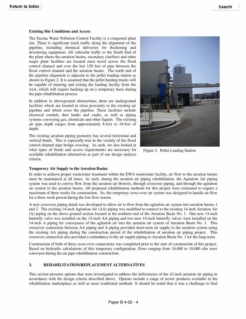
Existing Site Conditions and Access
The Encina Water Pollution Control Facility is a congested plant site. There is significant truck traffic along the alignment of the pipeline, including chemical deliveries for thickening and dewatering equipment. All vehicular traffic to the South End of the plant where the aeration basins, secondary clarifiers and other major plant facilities are located must travel across the flood control channel and over the last 120 feet of pipe between the flood control channel and the aeration basins. The north end of the pipeline alignment is adjacent to the pellet loading station as shown in Figure 2. It is assumed that the pellet hauling trucks will be capable of entering and exiting the loading facility from the west, which will require backing up on a temporary basis during the pipe rehabilitation process.
In addition to aboveground obstructions, there are underground facilities which are located in close proximity to the existing air pipeline and which cross the pipeline. These facilities include electrical conduit, duct banks and vaults, as well as piping systems conveying gas, chemicals and other liquids. The existing air pipe depth ranges from approximately 8-feet to 18-feet of depth.
The existing aeration piping geometry has several horizontal and vertical bends. This is especially true in the vicinity of the flood control channel pipe bridge crossing. As such, we also looked at what types of bends and access requirements are necessary for available rehabilitation alternatives as part of our design analysis criteria.
Temporary Air Supply to the Aeration Basins
In order to achieve proper wastewater treatment within the EWA wastewater facility, air flow to the aeration basins must be maintained at all times. As such, during the aeration air piping rehabilitation, the Agitation Air piping system was used to convey flow from the aeration air blowers, through crossover piping, and through the agitation air system to the aeration basins. All proposed rehabilitation methods for this project were estimated to require a maximum of three weeks for construction. So, the temporary cross-over air system was designed to handle air flow for a three week period during the low flow season.
A new crossover piping detail was developed to allow air to flow from the agitation air system into aeration basins 1 and 2. The existing 14-inch Agitation Air (AA) piping was modified to connect to the existing 14-inch Aeration Air (A) piping on the above ground section located at the northern end of the Aeration Basin No. 1. One new 14-inch butterfly valve was installed on the 14-inch AA piping and two new 14-inch butterfly valves were installed on the 14-inch A piping for conveyance of the agitation air into the aeration air system of Aeration Basin No. 1. This crossover connection between AA piping and A piping provided short-term air supply to the aeration system using the existing AA piping during the construction period of the rehabilitation of aeration air piping project. This crossover connection also provided a redundancy to the air supply piping to Aeration Basin No. 1 for the long-term.
Construction of both of these cross-over connections was completed prior to the start of construction of this project. Based on hydraulic calculations of this temporary configuration, flows ranging from 16,000 to 18,000 cfm were conveyed during the air pipe rehabilitation construction.
3. REHABILITATION/REPLACEMENT ALTERNATIVES
This section presents options that were investigated to address the deficiencies of the 42-inch aeration air piping in accordance with the design criteria described above. Options include a range of newer products available in the rehabilitation marketplace as well as more traditional methods. It should be noted that it was a challenge to find

Paper B-4-02 - 5
Figure 3. Large Diameter Sliplining
products in the trenchless rehabilitation marketplace that could meet the 250 degree F requirement. The following is a summary of alternatives that met the design criteria established.
Segmental Sliplining
Segmental sliplining is one of the most commonly used rehabilitation technologies and has been in the marketplace for over 50 years. It involves the installation of a smaller “carrier pipe” into the host pipe by discrete segments. The annular space between the carrier and host pipe is then grouted and the ends sealed. If designed as such, sliplining rehabilitation is a fully structural solution. Segmental sliplining pipe can be pushed into the host pipe relatively easily with equipment that is readily available and already in use by many contractors. Therefore, there are many contractors in the marketplace who have the equipment and ability to perform this work. Because of this, the installation costs of this technique are relatively lower than other alternatives. However, unique carrier pipe requirements which require special fabrication can add to the cost of this alternative. These requirements are discussed further in subsequent sections of this paper.
Access pits are required for insertion of the sliplined carrier pipe into the host pipe. Pits are typically positioned at bends and angle points in the existing pipe. This is because sliplining cannot be performed through horizontal and/or vertical bends greater than 2 degrees. For a pipe this size, traditional access pits would be approximately 9-ft by 25-ft. However, because of the tight site constraints, a portion of the sliplining process can be designed as short segment sliplining which would require smaller access pits.
At the other end of the sliplining process, the contractor usually establishes a reception pit. However, again because of the unique characteristics of this project and the tight site constraints, the project could be designed such that only a small excavation would be required at the reception location for connection of the new sliplined pipe into the existing aeration piping system. In total, set up area for equipment would require an area of approximately 25-ft by 50-ft.
Because of the temperature requirements associated with this project, carrier pipe materials are limited to materials suitable for high temperature air service. After extensive research, we determined that there are two pipe materials that would be appropriate for sliplining rehabilitation: stainless steel and industrial use fiberglass composite (Ameron Bondstrand). Each of these sliplining pipe systems would be designed as fully structural. This means that they would be able to withstand both static and dynamic earth loading as well as traffic loads. The jointing systems for each of these pipes would be air tight and able to withstand the 10 psi pressure requirements of this system. In addition, the annular space between the host pipe and the carrier pipe would be filled with grout. This would increase the structural integrity of the pipe and joint system. However, the carrier pipe would be air tested to ensure structural integrity of the joints prior to the installation of the grout. A temporary air supply to the aeration basins would be required during the rehabilitation process
The following is a summary of the characteristics for each of the pipe materials that are appropriate for the sliplining application:
Stainless Steel
Material Requirements: ASTM A240 annealed and pickled sheets and plates, Type 316, in accordance with ASTM A778 or ASTM A409 HT-0.
Inside Diameter: 36 inches
Pressure Rating: 50 psi
Wall Thickness for Structural Solution: Estimated at 3/16 inch plate, 0.188 inch wall thickness (Full design calculations are necessary to confirm this number.)
Joint Type: Welded or Arched-Band Type

Paper B-4-02 - 6
Maximum Temperature Tolerance: 400 degrees F
Pipe Segment Length: Fabricated as needed.
Precedent: Stainless steel pipe is commonly used in high temperature applications. However, it is usually provided in aboveground installation applications. Despite this fact, it can easily be fabricated for use in a slip lining application.
Ameron Bondstrand LD:
Material Requirements: Type “C” glass monofilament surfacing mat with silane finish and styrene soluble binder, chopped strand glass fiber reinforcement with a Type “E” glass continuous roving reinforcement, and thermosetting polyester or vinyl ester resin system. (See Figure 4.) Filament wound pipe is made by winding continuous fibrous glass strand roving onto the outside of a mandrel. The fiberglass reinforcement roving is saturated with either a liquid resin or a liquid resin / filler matrix. Winding is continued at predetermined angles and tension on the roving to achieve specific mechanical properties. The strength of the pipe is determined by the amount and orientation of the material wrapped on the mandrel.
Inside Diameter: 36 inches
Pressure Rating: 50 psi
Wall Thickness for Structural Solution: Estimated at 0.33 inches (Full design calculations are necessary to confirm this number.)
Joint Type: Double-O-Ring Gasketed Push-On Joint
Maximum Temperature Tolerance: 250 degrees F
Standard Pipe Segment Length: 20 feet
Precedent: This product is commonly used in industrial high temperature applications.
As illustrated in Figure 4, the Ameron Bondstrand LD is a composite fiberglass pipe. The corrosion liner (C) consists of a chopped glass strand applied by chopper gun or helically wound chopped glass strand mat cured with high temperature resin. The ratio of Resin to Glass is 70/30. The structural wall (S) consists of a computer controlled helically wound fiberglass rovings and resin. The ratio of Resin to Glass in this layer is 30/70. The outer surface (R) is a protective layer of high temperature resin. Total wall thickness (T) equals the combined thickness of the corrosion liner, structural wall, and resin-rich coating.
QuakeWrapTM
FRP and Carbon Fiber Fabric Lining
QuakeWrapTM FRP and Carbon Fiber Fabric Liners are high-strength glass or carbon fiber fabric that is impregnated in the field using a proprietary resin (V-Wrap 700 resin by VSL) with a high glass transition temperature of 300 degrees F. VSL has been using this resin in all of their FRP applications over the last three to four years. When cured, the fabric and resin combination form either a glass fiber reinforced polymer (GFRP) or carbon fiber reinforced polymer (CFRP) used to increase load capacity on structural elements such as pipe, tanks, columns,
Figure 4. Typical Wall Laminate Cross Section
Ameron

Paper B-4-02 - 7
beams, and slabs. Both fabrics are strong and lightweight. Therefore they are ideal for use in confined spaces. Both are non-corrosive and able to stand up to high temperatures environments. Both also far exceed the 10 psi system pressure requirements of Encina’s aeration piping.
For the Encina carbon steel application, a single glass layer closest to the steel host pipe followed by seven layers of carbon fiber layers was deemed most appropriate for the existing structural condition and loading of the host pipe.
Quakewrap FRP is applied by man-entry methods in the following steps:
1. Surface preparation of the pipe including removal of dust, laitance, grease, curing compounds, disintegrated
materials and other bond inhibiting materials from the surface. For application to an epoxy lined surface such as the 42-inch aeration pipeline, the contractor was required to thoroughly clean the liner and then roughen the surface to improve bonding capabilities.
2. Apply resin onto the substrate with a trowel to a nominal thickness of 40 mil.
3. Cut FRP fabric to the appropriate length for the application.
4. Saturate FRP fabric with resin.
5. Apply saturated fabric to the substrate surface.
6. Remove entrapped air bubbles under the fabric.
7. Repeat depending on how many layers is required to provide strength required for loading requirements.
8. Feather the edges of the applied fabric with resin.
9. Allow 24 hours for cure time.
Because it is installed via man-entry methods, this rehabilitation alternative can be applied to any angle bend. In addition, access pits are not required if there is sufficient means for a contractor to enter the pipe. Man-entry could be accomplished through an opening in the pipe created by the removal of one of the aboveground 90 degree bends. Access for airflow and safety would be provided at the other end of the alignment. Temporary air supply to the aeration basins would be required.
There is precedent for the V-Wrap 700 resin as manufactured by VSL for high temperature applications. In addition, there is precedent for the FRP Fabric Lining for large diameter structural pipeline repair. However, we were unable to locate precedent for the use of these two products together for high temperature application.
Mortar and Epoxy Composite Lining System
AP/M Permaform Corporation has developed a two-part cast in place sealing and reinforcing system using high strength, centrifugally cast specialty mortar then coated with a solids structural epoxy. The mortar material is an ultra high strength, high build, corrosion resistant mortar based on Portland cement fortified with micro silica. When mixed with the appropriate amount of water, a paste-like material will develop when sprayed onto the interior surface of the pipe. This mortar will harden quickly at ambient temperatures (240 minutes at 70 degrees F). The resulting material composition has excellent thin-section toughness, high modulus of elasticity, and is self-bonding. Polypropylene fibers are added
to the mortar mixture before it is applied to the interior of the pipe as an aid to casting, for increased cohesion, and to enhance flexural strength. When designed as such, the mortar lining provides full structural integrity to an existing pipeline.
The mortar lining is then coated with two-component 100 percent solids structural epoxy. It is applied from the same centrifugal cast applicator as the mortar for uniform distribution of the entire interior surface. It cures rapidly and forms a strong bond to freshly applied mortars (as mentioned above), which are formulated to prevent calcium
Figure 5. Quakewrap FRP Application
Figure 6. Mortar and Epoxy Composite Lining
Quakewrap
AP/M Permaform

Paper B-4-02 - 8
powders during hydration. The epoxy coating provides a smooth and homogenous protective layer that is impervious to corrosion and can withstand temperatures up to 300 degrees F.
Equipment associated with this rehabilitation alternative can be inserted into the existing pipe via openings at the 90 degree vertical angles for the aboveground portion of this system. As such, no additional access pits would be required, but access on each end is recommended and could be configured for future access to facilitate video camera inspection or entry. As with the other alternatives, temporary air supply to the aeration basins would be required.
High Strength Mortar:
Modulus of Elasticity (ASTM C-469): 28 day = 3,560,000 psi
Flexural Strength (ASTM C-293): 24 hours = min. 600 psi
28 day = > 1,080 psi
Compressive Strength (ASTM C-109): 24 hours = 3,000 psi
28 day = 8,000 psi
Tensile Strength: 682 psi
Shrinkage: None
Average liner thickness under heavy traffic loading and 16 foot hydrostatic head = 2 inches
(Note: Actual liner thickness would need to be calculated based on measured site conditions during final design.)
Structural Epoxy Coating:
Immersion temperature: 250 degrees F
Spike temperature (3 hour): 350 degrees F
Recommended force cure temperature: 200 degrees F for 6 hours
Total cure time: 12 hours for each application
VOCs = none
Minimum thickness: 0.375”
The mortar and structural epoxy coating systems have been around for many years and have been used in many projects as separate entities. However, existing projects using these technologies together could not be identified.
Open Cut
The open cut approach involves trench excavation, removal of existing piping, and placement of a new piping system. There are non-monetary considerations associated with this method including potential for damage, outages, and project delays associated with underground facilities crossing and in close proximity to the existing aeration system. Open cut replacement is further complicated by the depth of the pipeline in this location which would translate to a deep trench with costly sheeting and shoring. Therefore, unit costs associated with open cut cost estimating are assumed to be restrictively high. Because of high capital costs, longer staged installation time and other factors, open cut was not included in further considerations.
4. PROJECT DESIGN AND BID
Based upon the information provided above, the project was designed as both a sliplining project (where the Contractor could choose either stainless steel or Ameron Bondstrand) and a FRP fabric lining project. Two sets of plans were prepared and bid against one another in order to open up the project to the highest number of bidders, create a competitive bidding environment, and capture the lowest possible bid price. The lowest competent bidder proposed a combination of both sliplining with Bondstrand Pipe and Quakewrap FRP fabric lining. After careful consideration from the design team, it was determined that the Contractors requested solution was acceptable and
Figure 7. Structural Epoxy Coating
AP/M Permaform Corp.

Paper B-4-02 - 9
the design plans were altered to incorporate the rehabilitation alternative combination approach prior to the start of construction. At this time, the aboveground portion of the pipeline spanning the flood control channel was also redesigned for replacement with Ameron Bondstrand instead of Stainless Steel as the price of Stainless Steel piping at the time of bidding was exorbitantly high. 5. ISSUES DURING CONSTRUCTION
Existing Pipe Condition THE CHALLENGE: Because the 42-inch diameter air pipe was such a critical component to EWA’s secondary treatment process, it was impossible to take the pipeline out of service for inspection prior to the start of construction. When the cross connection was completed and the air pipe was finally decommissioned, access pits were dug and the pipe was exposed for inspection. At that time, it was determined that the steel pipe was in
the early stages of failure. The pipe was out of round by approximately
10% smaller than its original diameter in the vertical direction and now appeared to be an oval. Unfortunately, the sliplining pipe had already been ordered and had arrived on site. Because time was of the essence, the sliplining pipe had been pre-ordered so that it was available on site at the beginning of the 5 week shut-down period. EWA did not wish to rely on the cross connection piping set-up for longer than the 5 weeks. As such, the contractor was now faced with the problem of jacking a pipe whose bell OD was nearly the same size at the host pipe in the vertical direction.
THE SOLUTION: After consulting with the design team and the pipe manufacturer, the following steps were taken in order to ensure a successful sliplining project:
• Jacks were placed intermittently within the pipe so as to tack the crown of the pipe up until sliplining operations commenced. This was to prevent any further collapse of the pipe crown.
• Protrusions were ground down at the existing pipe joints.
• Grinding was completed along the existing steel spiral weld to provide as smooth of an internal surface as possible.
• Pipe lubricant was introduced in order to reduce any friction along the sliplining pipe surface as it was jacked into the host pipe.
• An alternate annular space grout mix was proposed and accepted. The alternate grout mix was designed as a thinner mix with better flow capabilities in order to successfully migrate through the tighter annular space.
Despite a tight fit and some initial difficulties during installation, the pipe went in relatively smoothly and was grouted successfully in place. Existing Utilities
THE CHALLENGE:
• Results of potholing during construction showed that the air pipe alignment, fittings, and appurtenance locations in field differed from those shown on plant records.
• Several utilities/facilities were found to be crossing air piping and were not shown on plant records.
Figure 8. The host pipe was out of round.
Figure 9. The host pipe was corroded.
Paper B-4-02 - 10
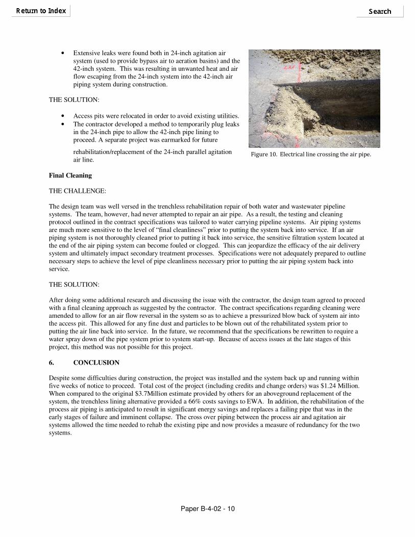
• Extensive leaks were found both in 24-inch agitation air system (used to provide bypass air to aeration basins) and the 42-inch system. This was resulting in unwanted heat and air flow escaping from the 24-inch system into the 42-inch air piping system during construction.
THE SOLUTION:
• Access pits were relocated in order to avoid existing utilities.
• The contractor developed a method to temporarily plug leaks in the 24-inch pipe to allow the 42-inch pipe lining to proceed. A separate project was earmarked for future
rehabilitation/replacement of the 24-inch parallel agitation air line.
Final Cleaning
THE CHALLENGE: The design team was well versed in the trenchless rehabilitation repair of both water and wastewater pipeline systems. The team, however, had never attempted to repair an air pipe. As a result, the testing and cleaning protocol outlined in the contract specifications was tailored to water carrying pipeline systems. Air piping systems are much more sensitive to the level of “final cleanliness” prior to putting the system back into service. If an air piping system is not thoroughly cleaned prior to putting it back into service, the sensitive filtration system located at the end of the air piping system can become fouled or clogged. This can jeopardize the efficacy of the air delivery system and ultimately impact secondary treatment processes. Specifications were not adequately prepared to outline necessary steps to achieve the level of pipe cleanliness necessary prior to putting the air piping system back into service. THE SOLUTION: After doing some additional research and discussing the issue with the contractor, the design team agreed to proceed with a final cleaning approach as suggested by the contractor. The contract specifications regarding cleaning were amended to allow for an air flow reversal in the system so as to achieve a pressurized blow back of system air into the access pit. This allowed for any fine dust and particles to be blown out of the rehabilitated system prior to putting the air line back into service. In the future, we recommend that the specifications be rewritten to require a water spray down of the pipe system prior to system start-up. Because of access issues at the late stages of this project, this method was not possible for this project. 6. CONCLUSION
Despite some difficulties during construction, the project was installed and the system back up and running within five weeks of notice to proceed. Total cost of the project (including credits and change orders) was $1.24 Million. When compared to the original $3.7Million estimate provided by others for an aboveground replacement of the system, the trenchless lining alternative provided a 66% costs savings to EWA. In addition, the rehabilitation of the process air piping is anticipated to result in significant energy savings and replaces a failing pipe that was in the early stages of failure and imminent collapse. The cross over piping between the process air and agitation air systems allowed the time needed to rehab the existing pipe and now provides a measure of redundancy for the two systems.
Figure 10. Electrical line crossing the air pipe.