relating the automation of functions in multi-agent
TRANSCRIPT

Relating the automation of functions in multi-agent control systems to a system engineering representation1 M. D. HARRISON, P. D. JOHNSON AND P.C. WRIGHT
Department of Computer Science, University of York, Heslington, York, YO10 5DD. UK.
Abstract
Engineers of safety critical systems are beginning to recognise that human issues are critical to their safe automation, and that appropriate techniques for taking account of the people in the system should be integrated into the design process. This chapter gives a brief introduction to a two-step decision procedure that can be used to help decide how to automate an interactive system. The procedure is intended for use early in the development of systems in larger scale collaborative settings with the aim of improving their safety and performance. Two issues are particularly important. The first concerns the appropriate choice of automation so that the tasks designed for the different roles satisfy criteria that have significance from a cognitive perspective. The second is to understand the mapping from concepts of function allocation to notations that are meaningful and usable by system engineers. The method has received preliminary evaluation in aviation and naval contexts.
Introduction
As the automation of complex processes becomes more achievable the need for system engineering procedures that help decide how to automate becomes more important to the safety and flexibility of automation use. Work systems are often complex interactive systems involving many people and many technology components. The work that is involved must be 1 In press, Handbook of Cognitive Task Design ed. E. Hollnagel.
implemented in a way that is most compatible with roles that are designed for the people involved. The implementation must satisfy general criteria such as minimising workload, maximising awareness of what is going on and reducing the number of errors. The basic problem therefore is to reduce the cognitive demands of the tasks being performed by the people involved in the system while maintaining fully their ability to function within their given roles. This chapter is concerned with these procedures, collected together in a process known as function allocation. It is also concerned with how these procedures can be integrated effectively with methods and representations that are used by system engineers. While many function allocation methods have been designed to be used by human factors experts, relatively little attention has been paid to the linkage of these methods to system engineering.
Allocation of function has evolved since the early 1950s. Methods that have been developed are problematic for a number of reasons.
• Context: They fail to take proper account of the context in which the
functions are to be automated. Functions are often considered in isolation using general capability lists describing what people are better at and machines are better at (Fitts, 1951). If context is to be considered it is presumed to be done implicitly by the appliers of the method. The cognitive task is therefore considered in isolation from the environment in which it is to be performed.
• Comprehension: They fail to be comprehensible and applicable by engineers. They depend on a firm understanding of human factors. For example the KOMPASS method (Grote et al., 2000) describes criteria for complementary system analysis and design: process transparency, dynamic coupling, decision authority and flexibility. These criteria are difficult to interpret. Methods do not use design representations that are familiar to system engineers. Allocation decisions are usually binary and, as a result, functions are identified as to be automated or not. This means that they must be described at a low level of granularity.
• Collaboration: They fail to recognise that the system is more than a single human and a single device. They do not take into account the broader collaborative system, the roles defined therein or the design of cognitive tasks that bridge across roles. They offer no guidance about how dynamic allocation of function should be implemented. This problem becomes more relevant as the possibility of automating a system dynamically, when necessary or appropriate, becomes more realistic.
Recent methods of function allocation have been developed to overcome some of these problems. In particular, one developed at the Institute of Work Psychology, University of Sheffield (Older et al., 1997) aims to overcome context problems while taking account of collaborative aspects of the organisation. Another method developed at the Department of Computer Science, University of York (Dearden et al., 2000) makes the decision procedures more explicit while also having a strong emphasis on context. This method also provides a clear representation for implementations of functions that automate some parts but not all of the functions (hereafter called partially automated functions).
Another approach which, although relatively weak at supporting the decision process or representing the context in which the functions are performed, has a strong representation of the output of the method in terms of a classification of levels of automation. These methods of automation classification, particularly (Parasuraman et al., 2000), are useful for introducing the important automation categories for different phases of the function. They work well in aiding the production of an output format. However, they are relatively difficult to convert into implementation for any given situation.
This chapter proposes a modest extension to the method described in (Dearden et al., 2000) aimed at addressing some of the concerns about collaboration and also ties more effectively to a format that can be understood by system engineers. In this method, roles can be assigned to parts of a function thereby defining some of the collaborative characteristics required in performing the function. In order to link with the requirements of system engineers, the system and modelling language UML (Unified Modelling Language) is used to represent elements required in the process of function allocation.
UML is a notation for describing different views of a system using different kinds of diagrams (Rumbaugh et al. 1999). It presumes an object-orientated design approach but, within this approach, provides a range of techniques for modelling important features of the design in a standardised notation. UML is of considerable interest in industry, particularly to those companies that are attempting to satisfy external requirements for human factors integration such as military organisations. The representations of UML can be used to describe the inputs and outputs to the method. If function allocation is to be made an explicit step in the system engineering development process then it must offer solutions to problems faced by engineers in the design of highly automated control systems. In practice function allocation is not often performed as an explicit step because results are perceived to be imprecise and benefit is unclear. Engineers recognise
that human operators are a source of error and attempt to solve this problem by minimising their role. The assumption is that doing this will have the effect of reducing these risks. Inevitably, situations arise that the automation cannot handle. In these circumstances the operators are expected to step in and resolve the situation. Because operators have been “out of the loop” their ability is impaired. The view of allocation of function is to keep operators in the loop in relation to their roles and to view automation as assisting them – it is therefore a problem of cognitive task design. The cognitive task design goal is to take advantage of the benefits offered by automation, but to do so in a way that does not impede the operators’ abilities to perform their roles. The achievement of this goal is difficult because it requires the combination of two disciplines, system engineering and human factors engineering, neither of which alone can provide the solution.
The chapter describes the proposed method in two passes. The first pass (next two sections) describes the essentials of the method while the second pass describes how the method provides support for the system engineering process. The next section gives a brief description of the method and describes in more detail what is required as input and what is produced as a result. This is followed by a more detailed description of the method, in particular the decision steps that are taken. The link between the allocation of function method and UML is then considered. The final section contains a brief description of possible further extensions to the method. It is possible to get an appreciation of how the method works without getting into the detail of UML. The process is fully described without reading the UML sections.
The ingredients of the method
Introduction
The problem is to take a set of functions, describing the work that the system is to do in the contexts in which the work is to be carried out, and to decide how to automate them. The procedure for automating functions involves two decision steps. Firstly, functions are matched to defined roles that capture high-level functions of the agents. In practice, it is often difficult to be clear about these roles at the outset. Initial definitions will be refined iteratively therefore through successive applications of the method. The aim is to decide how closely these functions fit the roles in a set of given scenarios. Functions that are entirely subsumed within a role are

proposed to be “totally manual within the role” – to automate would in effect remove part of the agent’s role. Functions that can be separated entirely from any of the roles and for which it is possible to automate are designated as “to be automated”. In practice few functions fit either of these categories. The functions that are left are therefore considered in more detail to decide what aspects of them should be automated. By this means automation can be designed in order to support specified roles most effectively. The effect therefore is to design cognitive tasks for the different roles specified and to render them in a form that can be employed by a system engineer.
In the following sub-sections we describe function, role and scenario in more detail. Other inputs to the method, for example: description of the technology baseline, mandatory constraints and evaluation criteria are also required as inputs. We leave a discussion of some of these issues until the section in which we consider UML aspects in more detail and others we ignore in order to maintain a clear description of the method. Function, role and scenario are the minimum needed to get a reasonable understanding of the method. The output of the method is a set of functions that can either be described as manual or totally automated and a set of partially automated functions. The format for partially automated functions is indicative of how they should be implemented.
Role
The aim is to consider the match between function and role as well as whether functions contain aspects that are most appropriate for humans or for machines. The machine or technology part of the system will be described generically as a device in what follows. In practice the design of roles, whether human or device, takes account of human considerations such as capability and training as well as the overall balance of the work design. Often, whether or not a function should be automated and how much it should be automated, depends on the context in which the function is performed. It makes more sense to be specific about how compatible the tasks are with the various roles specified for the various personnel in the particular contexts than to ask the question: “would it be sensible for a human to do this?” in isolation.
In practice role is difficult to define. It is an activity that can be performed either by a human or a device. Normally it is not necessary to produce a statement for a device’s role but there are circumstances where doing so is helpful in providing scope for the definition of a technology component. For example the envelope protection provided in a fly-by-wire aircraft (in other words the boundaries beyond which pilot manoeuvres are

judged to jeopardise the safety of the aircraft) could be clarified through an explicit role statement. Doing so would help to ensure that functions are not allocated in a way that prevents the device from being able to keep the plane within the safety envelope.
An example of a role statement for the captain of a civil transport aircraft might be:
The captain is the final authority for the operation of the airplane. The captain must prioritise tasks according to the following hierarchy: safety, passenger comfort and flight efficiency.
In the context of a single seat military aircraft an example role
statement for the pilot might be:
The pilot is the final authority for the use of offensive weapons and for evasive manoeuvres. The pilot is responsible for mission planning, tactical and strategic decision making and co-ordination with other aircraft. The pilot is responsible for the management of systems to maximise the probability of successful mission completion.
These roles may be taken as a starting position subject to refinement as
the allocation process unfolds. Ambiguities may be removed, assumptions may be seen as inappropriate, incoherence between roles may be resolved, role definitions changed to establish function integrity and vice versa.
Functions
A function or unit of work (an activity that the system - people and devices - is required to be capable of performing in order to achieve some result in the domain) might include “finding the current position of the vehicle”, “withdrawing cash” or “detecting a fire”. Although in practice, identifying and determining a function is a matter of expert judgement, some characteristics are important to prevent premature commitment to a means of automation. A function does not contain any indication of who or what performs it (Cook & Corbridge, 1997). For example, “key in way point” is not a function because it implies that the operator enters the way point manually, whereas “set way point” does not. Functions are related to, and can be derived from, the functional requirements used in system engineering. The assumption made in this process of function allocation is that, unlike typical practice, indications about who or what should perform the function are removed at the requirements stage.
Functions can be defined at a variety of levels of granularity and can be arranged hierarchically. In the same way as task analysis, a top down

hierarchical approach can be a useful aid to function elicitation and is also helpful in deciding what level of granularity of function can be used most effectively in the decision process. Descending the hierarchy reveals both a decrease in the complexity of the function and in the size of the sub-system required to perform it. At the top of the hierarchy, functions may be performed by a team or department, while at the bottom by a single operator with the aid of automation.
Scenarios
Function allocation methods such as the “Men are better at, Machines are better at” approach presume that the suitability of a function for automation is based on an individual function. They use capability lists usually based on the so-called Fitts’ List described in Table 1 (Fitts, 1951). Using this approach, functions are matched against the lists and, on the basis of the match, a decision is made whether to automate the function or not.
Men are better at… Machines are better at … Detecting small amounts of visual, auditory or chemical energy
Responding quickly to control signals
Perceiving patterns of light or sound
Applying great force smoothly and precisely
Improving and using flexible procedures
Storing information briefly, erasing it completely
Storing information for long periods of time and recalling appropriate parts
Reasoning deductively
Reasoning inductively Doing many complex operations at once
Exercising judgement
Table 1: Fitts’ List As has been noted already, these capability lists ignore the complex interactions and dependencies between activities of work. To overcome this the method described here considers groups of functions structured in the context of a scenario. This allows the designer to appreciate the interactions between the functions and therefore to understand more effectively those contextual factors that might influence the design of the cognitive tasks entailed by function allocation decisions. Scenarios focus upon situations

relevant to the decision criteria that are used to decide what level of automation is appropriate Examples of such criteria include workload and situation awareness. Scenarios aim to represent the functions under consideration in a range of contexts. For example, in the field of civil aviation where workload has been identified as a decision criterion, take-off and landing may be chosen as important as a basis for scenarios (among others such as emergency conditions) because these periods are recognised as producing high workload.
The method only considers those functions used within the current scenario and therefore the analyst must ensure that every function occurs in one scenario and ideally several. It is important to ensure that a variety of scenarios are used covering the range of activities that the functions will engage in. In order to achieve this, scenarios should be selected that cover all the normal operating conditions of the system. There is a wide range of sources for possible candidate scenarios, for example:
• The experience of practitioners in previous systems • Incident and accident reports for previous systems • Scenarios developed during the business modelling stage of the system
life cycle • Use cases and scenarios in the previous systems development
documentation or training manuals.
Scenarios often entail a detailed account of what happened in a set of circumstances. They are therefore concrete in terms of the actions that are described. If the scenario is describing some current possibility with the baseline architecture, these events will be expressed in implementation dependent terms. Once a scenario is elicited therefore, the description must be re-expressed neutrally in terms of functions (using the initial list of functions) rather than the baseline actions. The format for representing scenarios is based on a modified version of the scenario template for THEA (Pocock et al., 2001), and employs the UML format for scenarios described in (Cockburn, 2001), see Table 2.
This scenario description is then transformed. The events and event extensions headings are changed to functions and function extensions. The account of what happens in the scenario is re-expressed using the set of functions rather than the event descriptions. This process can be a useful check that the functions are expressed at an appropriate level and whether they incorporate too much implementation bias. The functional scenarios are then used as the basis for the two decision procedures.

The nature of the output
Function allocation methods typically consider functions at a very low level and provide two allocation options H (human) or M (machine). In many cases the designer’s interest lies with those higher-level functions that require some form of collaboration between operators and the devices in the system. The process is therefore concerned with how to implement these higher level functions in terms of how the collaboration or automation boundaries work. By this means, the cognitive tasks that are relevant to the potentially various human roles may be understood. Rather than working with numerous low-level functions to determine this boundary it is easier to work with the parent functions and to declare them as partially automated. Of course there are many ways in which the operators and devices can interact to execute a function and there is a need for the designer to specify how the collaboration will be achieved. UC# The name of the use-case Scenario 1 - Each use-case can have a number of scenarios Environment A description of the environment within which the
system is operating when the scenario occurs. Situation A description of the state of the system at the start of
the scenario. Are all the operators on duty, are there any known or unknown faults in the system etc.? Step Event 1 The main sequence of events that take place
during the scenario. This includes events that happen in the environment, events that cause changes to the system and the actions that the system must perform.
Sequence of events
… Step Event 1 Variations upon the main sequence of events are
recorded as event extensions.
Event extensions
… Scenario 2
Table 2: Scenario input template One possible approach is to use a classification that defines levels of automation with the aim that engineers recognise how to implement the

particular level. The allocation of function method then provides advice about appropriate automation in terms of level. A number of such classification schemes have been suggested. For example, (Sheridan & Verplanck, 1978) suggest a classification of levels in which decisions and control pass progressively from the human to the device. Later authors have produced alternatives. Kaber and Endsley provide ten levels of automation (Kaber & Endsley, 1997). Billings suggests seven levels of management automation (Billings, 1991). For each function that the designer defines as being partially automated there would be an indication of what the level of automation would be. (Parasuraman et al, 2000) goes further and suggests guiding the decomposition of functions into four broad classes: information acquisition, information analysis, decision and action selection, and action implementation. These functions are then automated according to Sheridan and Verplanck’s scale. In summary, all these approaches have in common the difficulties that: 1. They assume a spectrum of levels of automation between human and
device. In practice a number of different roles may carry out different functions.
2. They provide solutions that are not sufficiently clear to form a basis for engineering implementation of the functions.
Information Decision Action
Collect Propose Integrate Evaluate Configure Modify
Planning the response
Initiate response
Select
Approve
Supervise ongoing execution
Monitor progress
Identify exceptions
Revoke authority
Supervise termination
Determine output content
Identify completion
Stop process
Action Execute actions
Table 3: The IDA-S template

The approach used here, called IDA-S, (Dearden, 2001), provides more hooks for thinking about partial automation. It is based on Malinkowski et al.’s (1992) framework for adaptive systems and is capable of expressing all types of automation provided by the various classifications, splitting into four components that have common features with (Parasuraman et al. 2000). The top level components are Information, Decision, Action and Supervision (hence IDA-S). Each component is further split into a number of elements, each describing a particular aspect of the function. The designer specifies which role is responsible for performing that aspect of the function. If the element is not applicable within the context of the function then it is marked not applicable (n/a).
Function F1 Plan route Solution Sol6 Plot way-points
Design solution
The navigator plots a number of way-points describing the destination and the route required. The electronic chart evaluates the proposed route based upon its knowledge of navigation and sailing, proposing any changes or conflicts it identifies. The navigator can modify the route as required and approve the route. The electronic chart then calculates the distances and bearing between the points. The navigation officer supervises the entire process.
Information Decision Action Collect N Propose NIntegrate N Evaluate EConfigure N Modify N
Planning the response
Initiate response
N Select N
Approve
Supervise ongoing execution
Monitor progress
C Identify exceptions
C Revoke authority
C
Supervise termination
Determine output content
E Identify completion
N Stop process C
Action Execute actions
N
Table 4: Solution to plan route

The elements in the Information component cover issues such as which role integrates the information required to carry out the function, and which role is responsible for initiating a response. The Decision component covers such issues as which role proposes what plan/action to take, evaluates it, modifies it and selects one if there is more than one possibility. The Action component covers which role carries out the action. The Supervision component covers such issues as which role monitors the performance of the action, identifies exceptions and revokes the action if necessary. It allows the designer to express precisely how the function is implemented in terms of the various roles that are responsible for these aspects of the function. The given solution is indicated by placing the role identifiers in appropriate cells of the template.
Consider, for example, the automation of a function used in scenarios related to ship navigation, for example “plan route”. One solution is described in Table 4 in the format required by the method. This function allocation assumes the roles: Navigator (N), Electronic Chart (E) and the Navigation Officer or Command and Control (C).
The IDA-S definition clarifies how to develop an implementation that satisfies the requirements. The informal description, under the heading “Design solution” in Table 4, states in English which roles are responsible for what aspects of the function. The IDA-S representation invites the analyst to consider how to decompose the function and to consider which role should be responsible for what aspect of the function.
The method: two decision steps and consolidation
The approach contains two decisions. The first decision provides a first cut at how much automation to provide and hence prevents the system from being under- or over-automated. The second decision refines the situations where some level of automation is appropriate for a function. This step makes it easier for the analyst to work towards tasks that optimise performance, workload or situation awareness for example in the context of the different scenarios. The procedures aid the process of deciding what tasks are to be designed for what roles.
Can it be matched entirely to role?
Once roles, functions and scenarios have been defined the first decision step concerns which functions can be totally allocated to one of the roles (these roles may be device or human). Each scenario is considered in turn.
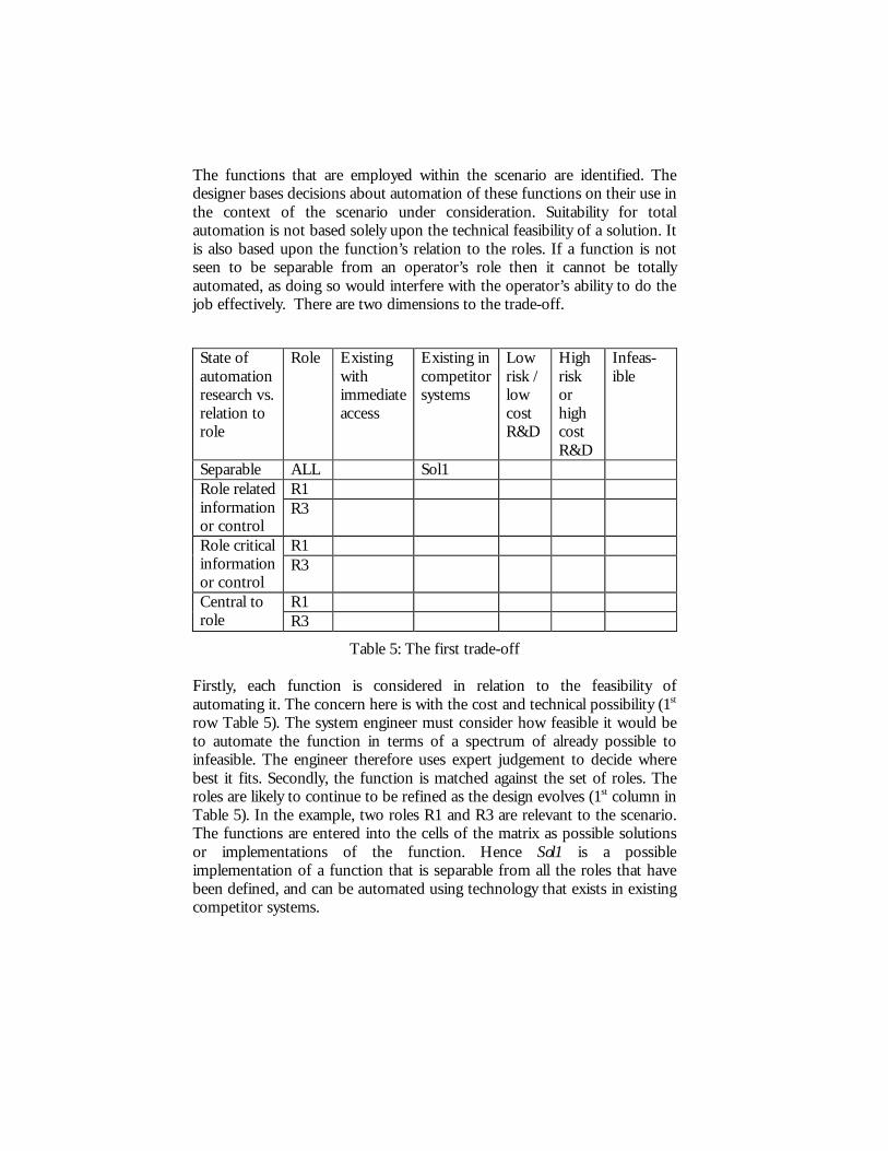
The functions that are employed within the scenario are identified. The designer bases decisions about automation of these functions on their use in the context of the scenario under consideration. Suitability for total automation is not based solely upon the technical feasibility of a solution. It is also based upon the function’s relation to the roles. If a function is not seen to be separable from an operator’s role then it cannot be totally automated, as doing so would interfere with the operator’s ability to do the job effectively. There are two dimensions to the trade-off. State of automation research vs. relation to role
Role Existing with immediate access
Existing in competitor systems
Low risk / low cost R&D
High risk or high cost R&D
Infeas-ible
Separable ALL Sol1 R1 Role related
information or control
R3
R1 Role critical information or control
R3
R1 Central to role R3
Table 5: The first trade-off Firstly, each function is considered in relation to the feasibility of automating it. The concern here is with the cost and technical possibility (1st row Table 5). The system engineer must consider how feasible it would be to automate the function in terms of a spectrum of already possible to infeasible. The engineer therefore uses expert judgement to decide where best it fits. Secondly, the function is matched against the set of roles. The roles are likely to continue to be refined as the design evolves (1st column in Table 5). In the example, two roles R1 and R3 are relevant to the scenario. The functions are entered into the cells of the matrix as possible solutions or implementations of the function. Hence Sol1 is a possible implementation of a function that is separable from all the roles that have been defined, and can be automated using technology that exists in existing competitor systems.

Two classes of functions can be distinguished using this trade-off. If a function can be separated from all the defined roles and is feasible (for example cost effective) to automate then it makes sense to totally automate it. On the other hand if the function is totally subsumed within one of the human roles, whether or not it can be automated feasibly, it makes sense to consider it as totally manual within the role. These functions can be identified by finding the functions that are “central to role” (rows 3 & 4 in Table 5) and appear in one of the high risk or infeasible columns (columns 6 & 7 in Table 5). However it is also likely that other functions that are central to one role may also be considered to be “manual” because it is important to that role’s activity that they perform the function manually however easy it is to automate. The class of functions that contains both the “wholly separable” and “entirely within role” types is not considered further in the method. If the function is to be automated then the means of automation is dealt with in some other component of the general development process. The interface to this functionality is of no concern here. Notice that a function may appear in more than one row because it relates to several roles but may only appear in one column because feasibility to automate is invariant. This leaves functions that are to be “partially automated”. There are usually a number of ways in which partial automation may be achieved. Choosing the most appropriate is the subject of the second trade-off that will be considered next.
The function “plan route” discussed earlier is critical to the role “navigator” (N) and related to the role “navigation officer” (C). In addition it might be reasonable to assume, depending on system engineering judgement, that the automation can be achieved through low risk / low cost research and development. Hence a potential solution to this function fits into the “partially automated” category and must be considered further. On the other hand, in the context of the definition of the “pilot” role defined earlier for a military aircraft, a function such as “fire missile” is central to role and, although it is technically feasible to automate, would be defined as manual even if there were no mandatory requirement to ensure that this should happen.
Candidates for the second step
The second decision procedure is concerned with comparing alternative IDA-S solutions defining partial automation possibilities with a “baseline” solution. The aim is to obtain, in the first instance, a set of most favoured IDA-S representations for each scenario in the sense that these function implementations have the most beneficial effect under criteria such as workload or situation awareness in the context of the scenarios. When this

has been done for each scenario, the choices are consolidated into a set of choices for the system as a whole. The result of this analysis will be to produce an implementation reflecting the function allocation decisions. Hence implementations will be produced that support most effectively the roles that are engaged in the scenario. Tasks will, in effect, be designed so that function implementations gather information, support decisions and support the most appropriate mechanisms for action and supervision optimally in the context of a set of criteria. In each scenario, comparison is made with the baseline design. Often the baseline is the existing design that is currently the subject of modification but there are circumstances where a new concept is being designed, where the most conservative of the design alternatives may be considered.
The rating process
Having constructed a number of alternative possibilities for each function listed from the scenario, these candidates are rated using a second matrix. An example of possible alternatives in the case of “calculate point to point information” would be for example: the navigation system might propose alternative routes from which the navigator selects the most appropriate; or no such choice being provided. The reason for choosing particular representations may be random or based on some assumptions about the abilities of the off-the-shelf technologies available to the project. The options for all these functions are then rated in relation to a criterion such as workload or performance in comparison with the “baseline” design.
In practice a collection of criteria will most likely be relevant to the current scenario, for example it may be appropriate to consider workload but not to the detriment of situation awareness. It is possible that the relation between the criteria will be uncertain, so for example improving workload may have a negative effect on situation awareness. The second decision is therefore made in relation to a “primary concern” (the most important criterion) in the context of the potential parallel effect on the other relevant criteria.
This decision step, therefore, takes all the options that have been produced for all the functions relevant to the scenario, and the primary concern identified, and enters them into a second matrix (see Table 6). The design options used in the baseline should also be included in the cell that is labelled “no significant improvement in primary concern”. The alternative solutions are then placed in the table. Two criteria decide where the solution should fit. The first depends again on the feasibility of the particular solution, how easy will it be to implement with achievable technology. The second requires a judgement about the effect of the solution in terms of the
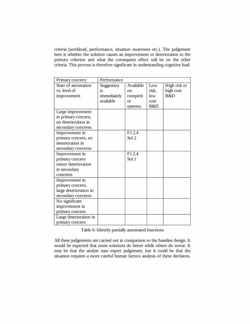
criteria (workload, performance, situation awareness etc.). The judgement here is whether the solution causes an improvement or deterioration to the primary criterion and what the consequent effect will be on the other criteria. This process is therefore significant in understanding cognitive load. Primary concern: Performance State of automation vs. level of improvement
Suggestion is immediately available
Available on competitor systems
Low risk, low cost R&D
High risk or high cost R&D
Large improvement in primary concern, no deterioration in secondary concerns
Improvement in primary concern, no deterioration in secondary concerns
F1.2.4 Sol 2
Improvement in primary concern minor deterioration in secondary concerns
F1.2.4 Sol 1
Improvement in primary concern, large deterioration in secondary concerns
No significant improvement in primary concern
Large deterioration in primary concern
Table 6: Identify partially automated functions All these judgements are carried out in comparison to the baseline design. It would be expected that some solutions do better while others do worse. It may be that the analyst uses expert judgement, but it could be that the situation requires a more careful human factors analysis of these decisions.

In this case it may make sense for a team to be involved and for the workload analyses or situation awareness calculations to be performed by appropriate experts.
In the case of the function “calculate point to point information”, if workload were the primary criterion and situation awareness the secondary criterion, the process might be as follows. If the baseline assumption was to be that the function was performed entirely manually, then solution 1 in which optional routes are presented to the navigator, would improve workload with no deterioration to situation awareness (because alternative route information is judged to be key to situation awareness by human factors experts). Solution 2, in which no options are presented, would also improve workload but would in the judgement of human factors experts cause minor deterioration to situation awareness.
Choosing the best candidates
Each potential solution is placed in the matrix. At the end of the process it will be possible to derive a set of best candidates, solutions that are most favourable in relation to the criteria and are technically feasible. By this means tasks will be designed in the scenario contexts. This process is achieved by searching from the top left of the matrix, selecting new design options. If a design option for a function is selected, then all other options for that function are deleted from the table. If a design option is selected from the ‘high risk research and development’ column, then an alternative, low risk solution should also be considered as a ‘fall-back’ position. In Table 6 two options are provided for a function F.1.2.4. Both are implementable because they are available on competitor systems. However the second solution is preferable because, while it results in an improvement in performance compared with the baseline solution, it has no negative effect on any of the secondary concerns such as workload.
After a number of options for functions have been selected, the designers should re-evaluate the scenario and consider whether or not the primary concern should be changed as a result of the decisions made so far. For instance, consider a scenario in which high workload is the primary concern. If new partially automated solutions are selected that significantly reduce the expected workload, then a different concern such as performance or situation awareness may now be more significant. If the primary concern is changed, then options for the remaining functions are re-arranged in a new matrix reflecting the changed priorities. Option selection then proceeds as before, starting with the options that provide the
greatest improvement for the new primary concern. This procedure iterates until one design option has been selected for every function.
One possible outcome of the procedure is that some functions cannot be successfully allocated without making use of options from the ‘high risk research and development’ column, or from a row involving a ‘large deterioration’ with respect to a secondary concern within the scenario. If this occurs frequently, and cannot be solved by generating alternative design options, this may indicate a need to review the system requirements, or to review assumptions about the number and role of human operators in the system.
Emerging functions
When a design option for each function has been selected, the scenario is re-analysed using the proposed allocations as the set of baseline designs. The purpose of this re-analysis is to identify any new functions that may be an emergent consequence of the new design. Such functions could include for example a requirement to co-ordinate two separate functions that control the same system resources (for example, in one domain we considered, we recognised that both ‘terrain following’ and ‘missile evasion’ had similar IDA-S characterisations and could be combined as variants of the same function). Design proposals for the partial automation of these functions are made. Hence the task is redesigned in the light of the analysis.
If new functions are identified, then designers must consider whether their impact upon criteria such as performance, workload or situation awareness is acceptable. If the emergent functions do create an unacceptable situation, then the selection matrix is revisited to consider any options that might improve outcomes for the emergent functions. This may result in changing the level of automation, or may result in changed selections for the original functions. Hence, if emergent functions are identified then steps of the process dealing with these are repeated, that is feasible design options are suggested for partially automating the emergent functions and the optimum choice is selected. These new functions may have unexpected effects on the work and therefore the whole process of function allocation must be considered again using these new functions. In situations where these functions might be particularly critical it may be necessary to find new scenarios in which combinations of features may be considered.
Consolidation
Once functions within each scenario have been allocated, any contradictions of allocation across scenarios are resolved. This is done either by changing one of the allocation decisions so as to resolve the conflict or by allowing automation levels to change across scenarios. Components of IDA-S allocations can be transferred from one role to another during the activity supported by the system. This redistribution typically occurs in response to a change in the environment or a change in the state of one of the agents. The designer must decide how the allocation of function changes and the extent to which the operator is involved in this process. In practice the change-over can be seen as another function that can be refined in the same way as any other function that emerges during the process.
The following section describes in more detail how the method is integrated with UML. A reader only interested in the method may skip to the final section (Extension and Conclusions).
Integration with UML
Two further developments of the method make it more accessible to system engineers. The first reformulates the representations that are input and output for the method into UML (Rumbaugh et al., 1999). The second produces a representation of the mapping between the roles and system components. The aim of the first step is that the method can be more easily assimilated into existing system engineering practice and of the second that the implementation of roles may be more easily visualised. In other words an additional dimension is introduced, that of recognising how a role is implemented either as a human or a device within the system. In earlier sections issues of feasibility of automation were discussed without considering the architecture of the system.
Integration of input
The previous discussion of scenarios and functions has already indicated that they can be represented using UML’s use-case model. The advantage of this approach is that system engineers may use a UML supported design process (or profile) to develop the system’s design model based upon the use-case model. Function allocation can therefore be inserted into the development process at the point during which the use-case model (a representation of requirements) is transformed into the design model.
A UML use-case describes a collection of scenarios related to an actor’s goal (Jacobson, 1995). The use-case is the general goal and scenarios are a sample set of means by which the goal can be achieved. This has a strong similarity with the goals, sub-goals, actions and plans of Hierarchical Task Analysis (Kirwan & Ainsworth, 1992). Each scenario contains a different description of who does what in order to fulfil the goal. At least one scenario must describe the normal set of steps taken to fulfil the goal successfully. The other scenarios can describe alternative ways of fulfilling the goal or ways in which the goal may fail to be fulfilled. Failure may occur because of operator error or mechanically induced faults or unexpected events in the environment. It must be made clear that any erroneous steps are not the required functionality of the system. Use-cases also describe what guarantees the system provides for the other stakeholders. Together the use-cases form a model of the system’s behaviour known as the use-case model.
Use-case template
Cockburn suggests a more detailed description of use-cases than proposed in the standard (Rumbaugh et al, 1999). He proposes that the sequential description of a use-case should consist of a sequence of steps each taking the form ‘Subject…verb…direct object… prepositional phrase’ (Cockburn, 2001). The description can also include statements that control the flow, for example REPEAT <x1 - xx> UNTIL <condition> or STEPS <x1 - xx> ANY ORDER. Since a specific instance of behaviour in scenarios is being described, conditional branches such as the IF statement can be avoided.
The scenario should describe the functions to be allocated but should not pre-empt allocation, therefore the system element (to be discussed in more detail below) responsible for performing the function should be unspecified unless it has already been formally decided. The scenarios associated with allocation of function are therefore grouped according to goal as defined by the use-case. The set of scenarios covering all the use-cases should cover all the functions that are candidates for function allocation.
An example of a use-case scenario is shown below. The example is based upon a ship navigating from open sea along a familiar channel into harbour. Only the main success scenario is shown. The description has three columns: step number; the role or roles that carry out the functions; the functions themselves in the order that they are to be performed. As the allocation of function is completed then the roles responsible for providing

each function, extracted from IDA-S descriptions, can be inserted into the middle column, see Table 7. Step Role(s) Function Description 1 Captain orders the ship into harbour 2 Navigator/ Electronic chart plans the route into harbour 3 GPS subsystem obtains the ship’s current fix 4 Electronic chart plots the ship’s current fix 5 Navigator/ Electronic chart calculates direction, time and
appropriate speed to next checkpoint
6 Navigator sends calculated information to helmsman as required
7 Repeat steps 3 to 6 until ship is docked
Table 7: A use case with roles In one of the preferred UML design processes, the so called Rational Unified Process (Rumbaugh et al., 1999a), the use-case model is created during the ‘Requirements’ workflow and is realised as an analysis model during the ‘Analysis and design’ workflow. The analysis model is a design model that ignores any specific implementation issues and may be used to implement an object oriented software analysis design using any object oriented language. The diagrammatic notations available to the analysis and design models can be used to produce views of the allocation of function.
These tables provide the developer with a fuller description of the distribution of functionality than is possible using the use-cases. Table 8, 9 and 10 give a full representation of the scenario in this format. Table 8 provides the “characteristic information”, that is information about the general circumstances in which the scenario takes place. Table 9 provides the main success scenario, similar to that described in Table 7. Table 10 describes related information that is valuable in understanding the circumstances in which the scenario takes place.
Characteristic Information The characteristic information (Table 8) includes a description of the overall goal to which the scenario relates, the pre- and post-conditions that govern the specific circumstances of the scenario and the actors that are involved.

It also describes what a successful end condition would be as well as possible failure situations. Some of the information contained here may be used in formulating the extent to which different criteria are relevant to the scenario during the process of deciding the effect of alternative IDA-S solutions in terms of the criteria within the scenario. Human factors experts may use this part of the scenario to place their assumptions about the situation.
Goal In Context: The goal is to navigate the ship from the open sea
into and along a channel so that it safely comes into harbour.
Scope: System Level: I User goal Pre-Condition: 1. Ship is in open sea close to harbour (less than 1
hour away) Rationale for scenario:
Approaching harbour is recognised as a high workload period for the navigation system. It is also a period during which the fixes and projected fixes must be highly accurate.
Success End Condition:
1. The ship is stationary 2. It is alongside the correct point on the quay 3. It has not hit anything
Failed End Condition:
1. The ship hits an object
Minimal guarantees: 1. The ship will not be navigated into an obstruction
Primary Role: Captain Stakeholder roles: 1. Crew – safety
2. Helmsman - requires navigation information to steer the ship.
Trigger Event: The order is given to sail into harbour
Table 8: Characteristic Information
Main Success Scenario Table 9 describes the main success scenario. This is the central scenario that will form the basis for function allocation in normal circumstances. There may be other scenarios that describe extreme or exceptional behaviour that may also be taken into account, and these may be used to consider

circumstances where dynamic function allocation may be appropriate. Such decisions will mean that these scenarios will require modification to include functions that are concerned with the decision about which function to perform.
In this particular example it is imagined that the function allocation process is in progress. The first step, that is the decision about whether functions should be totally manual or totally automated has been completed and the function in step 1 is entirely manual, performed by the captain role. The remaining steps involve functions for which appropriate IDA-S representations must be selected.
Situation and environment:
This scenario assumes that the ship is arriving at a familiar harbour for which an up to date chart is available. The approach takes place during daytime and in good weather. The ship is not obstructed by any other vessels and there are no technical or human failures.
Step Role(s) Function Description 1 Captain orders the ship into harbour 2 <N/A> plans the route into harbour 3 <N/A> obtains the ship’s current fix 4 <N/A> plot the ship’s current fix 5 <N/A> calculates direction, time and
appropriate speed to next checkpoint
6 <N/A> sends the calculated information to the helmsman as required
7 Repeat steps 3 to 6 until ship is docked
Table 9: Main Success Scenario
Related Information Related information that may be used by both system engineers and analysts in the allocation of function process provide the last element in the scenario description (Table 10). This information includes version and project schedule information as well as information about the frequency of the scenario, the roles that are involved and issues of accountability.

Schedule: <Date/build the use case can be tested>
Priority: Must Performance Target: <If applicable, how fast should this
use case proceed> Frequency: Twice a month Super Use Case: Navigate Sub Use Case(s): Channel To Primary Role: Navigation officer accountable for
navigation Secondary Role(s): <List the secondary roles, these are
the roles the system kicks to get something done. Note, the primary role kicks the system to get something done>
Channel(s) To Secondary Role(s): <How do we get to the secondary roles>
Table 10: Related role information
Integration of output
The output from the allocation of function method is not easily translated into UML. Two types of information have to be expressed. The first is the representation of the partially automated functions (the IDA-S representations defined in UML terms). The second issue has not yet been dealt with in the description of the method. A set of representations is required that describes how the roles are implemented in terms of the elements of the system. The IDA-S representations are expressed as UML activity diagrams. An activity diagram can be divided into a number of columns (called swim-lanes in UML) each of which is assigned a particular role. Any activities that lie within a column are the responsibility of that role. A partially automated function is expressed by creating a column for each role involved and by representing each element of the IDA-S as an activity placed in the appropriate columns (see Figure 1). This representation of partially automated functions requires a little more design commitment than the IDA-S matrix representation. In particular it requires the analyst not only to suggest partially automated solutions, in which the different roles perform different parts of the function, but also to decide the order in which these function components are performed. In practice, it

appears that in order to understand which role performs what part of the function some idea of order is required. This extra detail provides important information that can be used in the assessment of workload or situation awareness.
Figure 1: Representation of a partial function using an activity diagram. Hence in Figure 1 it is stated that collection, integration, configuration
and proposing will be done in sequence by the device for the function set/adjust aimpoint. Evaluation, however, which is done next will be shared between the human and the device. The pilot will modify the information and select and authorise in the context of execution.
Apart from brief mention of baseline architectures, little has been said about the system architecture in terms of which the function allocation is conceived. What aspects of the system will be feasible to automate or not for example? An important aspect of this description is to find a means of representing roles in terms of system components. The UML proposal provides tags or stereotypes for describing the system elements. These are the basic ingredients that engineers use UML to represent. Because UML is
S t a r t P o in t
M a c h in e - S e t / A d ju s t a im p o in t
C o l le c tI n f o r m a t io n
P i lo t - S e t / A d ju s t a im p o in t
I n t e g r a t e
C o n f ig u r e
P r o p o s e
E v a lu a t eE v a lu a te
M o d i f y
S e le c t
A u t h o r is e
A b a n d o n
A b a n d o n
A d ju s t
O k
A d ju s tO k
I n i t ia t eR e s p o n s eE n d P o in t
K e y

intended to be used generically, it provides a notion of profile as a means of supporting a particular development process directly. Profiles therefore involve a method and a collection of defined elements (described by stereotypes) in order to support a particular development process. Two standard profiles are relevant to the process that surrounds allocation of function, the profile for software development and the profile for business modelling. These profiles contain some of the elements that are required to support the method envisaged here but other components that have been described in the chapter are not included. More detail on the UML extension mechanisms is contained in the ‘UML Toolkit’ (Eriksson & Penker, 1997) or ‘OMG Unified Modeling Language Specification’ available at the OMG web site (OMG, 1999).
Stereotypes FA model element Meta-element Profile for
Software Develpmnt
Profile for Business Modelling
Customised UML profile for Function Allocation
Function Op Function Role C Role
Component
P Subsystem
Human C Worker
System element class
Device C Device Component
O Subsystem
Human O Worker
System element
Device O Device
Table 11: Mapping Function Allocation to UML (Op=operation, C=class, P=package, O=object)
The first distinction required in describing architectures is between system element classes and system element instantiations. A class, “naval rating” for example, will have as instantiation a particular naval rating. System element classes required by the allocation of function method must distinguish between human and device as well as describe groupings of such elements, teams for example. A team may consist of human and device components. In addition neither of the profiles that are presumed in this method include

stereotypes associated with function or role. For this reason stereotypes <<Function>> and <<Role>> are included.
Therefore, in addition to the stereotypes required by the software development and business modelling profiles, further stereotypes are included as part of the allocation of function profile to support the allocation of function method. These stereotypes are: <<Subsystem>>, <<Worker>>, <<Device>>. It is assumed therefore that system engineers are already fluent with UML software development and business process profiles and therefore little additional overhead is involved in using these additional tags. Table 11 describes the new customised profile for function allocation along with the stereotypes used from business modelling and software development. Note that underlining the stereotype implies instantiating the class.
Hence the function allocation method uses two existing stereotypes concerned with software development and business modelling and adds to them the extra stereotypes defined. The aim is that the process subsumed within the UML software development and business modelling profiles will form the basis of the function allocation approach described in earlier sections of this chapter.
Figure 2: Role participation diagram
The final representations for use by system engineers indicate (1) how roles participate in scenarios, and the nature of the participation (Figure 2), (2) which functions relate to which roles (Table 11) and (3) how the roles are implemented in terms of system elements (Figure 3). The role participation
<<Role>>Fixing
(from Roles)
<<Role>>Navigator(from Roles)
<<Role>>Navigation Officer
(from Roles)
<<Role>>Plotting
(from Roles)
<<realization>>Navigate into harbour
<<participant>>
<<participant>> <<participant>>
<<participant>>
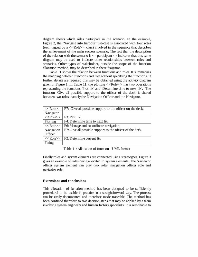
diagram shows which roles participate in the scenario. In the example, Figure 2, the ‘Navigate into harbour’ use-case is associated with four roles (each tagged by a <<Role>> class) involved in the sequence that describes the achievement of the main success scenario. The fact that the description of the relation with the scenario is <<participant>> indicates that this same diagram may be used to indicate other relationships between roles and scenarios. Other types of stakeholder, outside the scope of the function allocation method, may be described in these diagrams.
Table 11 shows the relation between functions and roles. It summarises the mapping between functions and role without specifying the functions. If further details are required this may be obtained using the activity diagram given in Figure 1. In Table 11, the plotting <<Role>> has two operations representing the functions ‘Plot fix’ and ‘Determine time to next fix’. The function ‘Give all possible support to the officer of the deck’ is shared between two roles, namely the Navigation Officer and the Navigator.
<<Role>> Navigator
F7: Give all possible support to the officer on the deck.
<<Role>> Plotting
F3: Plot fix F4: Determine time to next fix.
<<Role>> Navigation Officer
F6: Manage and co-ordinate navigation. F7: Give all possible support to the officer of the deck.
<<Role>> Fixing
F2: Determine current fix
Table 11: Allocation of function - UML format Finally roles and system elements are connected using stereotypes. Figure 3 gives an example of roles being allocated to system elements. The Navigator officer system element can play two roles: navigation officer role and navigator role.
Extensions and conclusions
This allocation of function method has been designed to be sufficiently procedural to be usable in practice in a straightforward way. The process can be easily documented and therefore made traceable. The method has been confined therefore to two decision steps that may be applied by a team involving system engineers and human factors specialists. It is reasonable to

expect that the process could be performed by system engineers if they subcontract the process of assessing the criteria related questions in the decision step to human factors experts. The UML representations have been introduced to provide formulations of inputs and outputs that are directly usable by system engineers and have indicated proposed extensions to standard UML profiles.
Figure 3: Allocation of roles to system elements - UML format The method has been used in a realistic case study within QinetiQ (formerly the UK Defence Evaluation Research Agency - DERA) based on a ship-based fire emergency system. Information about whether the proposed function allocations influenced the design of the system are not available.
The application of the method was reviewed by practitioners (system engineers, human factors experts and domain experts) in the context of a two day workshop at QinetiQ. During the workshop, results from the case study were presented and participants were invited to consider a specific scenario, to apply the decision procedures and produce the appropriate representations. The participants were divided into teams involving one naval officer, system engineers and human factors experts. Useful
<<Worker>>Navigator
(from System elements)
F7: Give all possible support to theofficer of the deck()
<<Role>>Navigator
<<Worker>>Navigation officer
(from System elements)
<<Machine>>GPS
(from GPS)
<<Machine>>Electronic chart
(from Electronic chart)
F6: Manage and co-ordinate navigation()F7: Give all possible support to the officer ofthe deck()
<<Role>>Navigation Officer
F2: Determine current fix()
<<Role>>Fixing
F3: Plot fix()F4: Determine time to next fix()
<<Role>>Plotting
<<Plays>>
<<Plays>>
<<Plays>> <<Plays>>
information about the method came out of the review. It was felt that the IDA-S template was too complicated. The purpose behind its design was that it provided a representation that would help engineers produce solutions based on proposals made by human factors experts. It was aimed at helping human factors experts to consider key aspects of the automation of the interface as it relates to user tasks. The problem with it was associated with seeing how all the elements specified in the IDA-S template related to a particular function. As a result of this feedback, alternatives to IDA-S are being considered. In particular we are concerned with attributes of a solution that are simpler to understand by all participants in the allocation of function process. The second problem concerned the initial proposal for mapping roles to system architectures. It was felt that the connection between roles and system elements was too complicated and as a result the method presented in this chapter is a simplification. This continues to be an issue that is under exploration.
A further area where the method is perhaps too simplistic and untried is that of adaptive automation. A simplifying presumption is that automation adapts by function substitution and that in all cases the result is the same. In practice both assumptions may be false. As noted by (Sperandio 1978), in discussions of air traffic control, different strategies are adopted depending on the number of aircraft in the air space. Sequences of functions making up procedures rather than individual functions are substituted. It may also be appropriate that dynamic mechanisms should be prepared to shed certain less critical functions in the face of hard deadlines. Both these issues are discussed in more detail in (Hildebrandt & Harrison 2001).
Acknowledgements:
We would like to acknowledge the contributions of Andrew Dearden, Colin Corbridge and Kate Cook to this work. It has been funded successively by two companies BAE SYSTEMS and QinetiQ (DERA CHS).
References
Billings, C.E. (1991). Human-Centered Aircraft Automation. Technical report number 103885. NASA AMES Research Center. USA.
Cockburn, A. (2001). Writing effective use cases. Addison-Wesley. Cook, C.A. and Corbridge, C. (1997). Tasks or functions: what are we
allocating? In E. Fallon, L. Bannon & J. McCarthy (Eds.) ALLFN’97 Revisiting the Allocation of Function Issue: New Perspectives, pp. 115-124. Louisville KY: IEA Press.
Dearden, A., Harrison, M.D. and Wright, P.C. (2000). Allocation of function: scenarios, context and the economics of effort. International Journal of Human-Computer Studies, 52, 289-318.
Dearden, A.M. (2001). IDA-S: a conceptual framework for partial automation. In A. Blandford, J. Vanderdonckt and P. Gray (Eds.) People and Computers XV – Interaction without Frontiers. Proceedings of IHM-HCI 2001. Springer. Berlin. pp. 213-228.
Eriksson, H. and Penker, M. (1997). UML Toolkit. John Wiley & Sons. Fitts, P.M. (1951). Human engineering for an effective air navigation and air
traffic control system. In D. Beevis,, P. Essens, and H. Schuffel (Eds.) Improving function allocation for integrated systems design. CSERIAC SOAR 96-01. Wright Patterson Air Force Base. OH. USA.
Grote, G., Ryser, C., Wafler, T., Windischer, A. & Weik, S. (2000). KOMPASS: a method for complementary function allocation in automated work systems. International Journal of Human Computer-Studies. 52 267-288.
Hildebrandt, M. & Harrison, M.D. (2002). The temporal dimension of dynamic function allocation. Paper to be presented at Eleventh European Conference on Cognitive Ergonomics. Catania, Italy, 8-11 September.
Jacobson, I. (1995). Use cases and scenarios. In J.M. Carroll (Ed) Scenario-based design: envisioning work and technology. John Wiley & Sons.
Johnson, P.D., Harrison, M.D. & Wright, P.C. (2001). An evaluation of two methods of function allocation. People in Control IEE Press. Conference Publication No. 481, 178-183.
Kaber, D.B. & Endsley, M.R. (1997). The combined effect of level of automation and adaptive automation on human performance with complex, dynamic control systems. In Proceedings of the Human Factors and Ergonomics Society 41st Annual Meeting. pp 205-209. Santa Monica CA.: Human Factors and Ergonomics Society.
Kirwan, B. and Ainsworth, L.K. (1992). A guide to task analysis. Taylor and Francis.

Malinkowski, U., Kuhme, D.H. and Schneider-Hufschmidt, M. (1992). A taxonomy of adaptive user interfaces. In A. Monk, D. Diaper and M.D. Harrison (Eds.) People and Computers VII, Proceedings of HCI’92. Cambridge University Press. pp 391-414.
Older, M.T., Waterson, P.E. & Clegg, C.W. (1997). A critical assessment of task allocation methods and their applicability. Ergonomics, 40, 151-171.
Object Management Group (1999) ‘OMG Unified Modeling Language Specification’, ver 1.3, http://www.omg.org
Parasuraman, R. & Mouloua, M. (Eds). (1996). Automation and human performance: theory and applications. Lawrence Erlbaum Associates.
Parasuraman, R., Sheridan, T.B. and Wickens, C.D. (2000). A model for types and levels of human interaction with automation. IEEE Transactions on Systems, man and cybernetics- part A: systems and humans. 30, 286-296.
Pocock, S., Harrison, M.D., Wright, P.C. and Johnson, P.D. (2001). THEA: a technique for human error assessment early in design. In M. Hirose (Ed.) IFIP TC 13 International Conference on Human-Computer Interaction. IOS Press. Ohmsha. pp. 247-254.
Rumbaugh, J., Jacobson, I. and Booch, G. (1999). The unified modelling language reference manual. Addison Wesley.
Rumbaugh, J., Jacobson, I. and Booch, G. (1999a). The unified software development process. Addison Wesley.
Sheridan, T.B. and Verplanck (1978). W.L. Human and computer control of undersea teleoperators. Technical report. Man-machine systems lab, Dept of Mechanical Engineering, MIT, Cambridge, MA.
Sperandio, J.-C. (1978). The regulation of working methods as a function of workload among air traffic controllers. Ergonomics. 21,195-202.
Acronyms: UML (Unified Modelling Language), IDA-S (template for partially automated functions based on Information, Decision, Supervision and Action).
Keywords: allocation of function, automation, system engineering, unified modelling language (UML), scenarios, use-cases