relation between hydrogeological setting and swelling ... · the lining or uplift of the entire...
TRANSCRIPT

NOTICE: this is the author’s version of a work that was accepted for publication in Engineering Geology. Changes resulting from the publishing process, such as peer review, editing, corrections, structural formatting, and other quality control mechanisms may not be reflected in this document. Changes may have been made to this work since it was submitted for publication. A definitive version was subsequently published in ENGINEERING GEOLOGY 122 (3-4), 204-214, (2001), DOI: 10.1016/j.enggeo.2011.05.009
1
Relation between hydrogeological setting and swelling potential of
clay-sulfate rocks in tunneling
Christoph Butscher1, Peter Huggenberger
2, Eric Zechner
2, Herbert H. Einstein
1
1
Massachusetts Institute of Technology, Department of Civil and Environmental Engineering, 77
Massachusetts Avenue, Cambridge, MA 02139, USA 2
University of Basel, Institute of Geology and Paleontology, Applied and Environmental
Geology, Bernoullistrasse 32, 4056 Basel, Switzerland
Corresponding author: Christoph Butscher, e-mail: [email protected], phone: +1 617 715 4766,
fax: +1 617 253 6044
Abstract
In this study, an approach to estimate the swelling potential of clay-sulfate rocks in tunneling is
presented. Swelling of clay-sulfate rocks leads to damage in tunnels that is difficult and costly to
repair. Swelling is caused by the transformation of the sulfate mineral anhydrite into gypsum,
which involves an increase in rock volume in a system open to water flow. Knowledge of the
hydrogeological situation and the groundwater flow systems at the tunnel is essential to better
understand the swelling processes. The present study was conducted for the Chienberg tunnel in
Switzerland. It investigates the hydrogeological situation of four zones in this tunnel crossing the
Triassic Gipskeuper formation. In two of them, heavy swelling occurred after tunnel excavation,
while in the other two no swelling occurred. In addition, the groundwater flow systems before and
after tunnel excavation are investigated based on numerical flow modeling. The findings suggest
that in certain situations after tunnel excavation, depending on geological and changing hydraulic
conditions, the excavation damaged zone around the tunnel provides a “hydraulic short circuit”
between the weathered Gipskeuper and the anhydrite-bearing strata of the unweathered
Gipskeuper. As a result, water from the weathered Gipskeuper gets in contact with anhydrite,
triggering its transformation into gypsum and, thus, rock swelling. The results of the study may
also contribute to improved swelling experiments in the laboratory and a more reliable planning of
restoration measures in tunnels that are damaged by rock swelling.
Keywords: tunnel engineering; swelling; clay-sulfate rocks; groundwater flow
1. Introduction In mountainous regions, as well as in urban areas and in landscapes that deserve to be protected,
transportation strongly relies on tunnels. Also, in view of increasing demand for fast and efficient
transportation, the importance of tunnels is likely to increase in the future. The EU Member states
and the EU, for example, are investing approx. EUR 23 billion in the current “Trans-European
Network” (TEN) program, which aims at upgrading European railway networks, including many
new tunnel sections. In southern Germany, northern Switzerland and eastern France, the
geological strata of the “Germanic Trias” are widely spread, and many tunnels in these regions
have to cross the Triassic Gipskeuper formation. The Gipskeuper (“Gypsum Keuper”) is feared in
tunneling, because this formation contains clay-sulfate rocks that are subject to heavy swelling
(Einstein, 1996; Anagnostou et al., 2010). Examples of major swelling problems in existing
tunnels include tunnels in the Jura Mountains of France and Switzerland and tunnels around the
Stuttgart metropolitan area in Germany (Steiner, 1993). In Stuttgart, the major railway project
“Stuttgart 21” is currently starting, which will include 16 new tunnels with an estimated length of
~15 km crossing the Gipskeuper. There are more tunnel kilometers to be built in this formation
than the total length of all Gipskeuper sections in existing tunnels. In addition to these railroad
tunnels, new road tunnels are being constructed in these regions.

NOTICE: this is the author’s version of a work that was accepted for publication in Engineering Geology. Changes resulting from the publishing process, such as peer review, editing, corrections, structural formatting, and other quality control mechanisms may not be reflected in this document. Changes may have been made to this work since it was submitted for publication. A definitive version was subsequently published in ENGINEERING GEOLOGY 122 (3-4), 204-214, (2001), DOI: 10.1016/j.enggeo.2011.05.009
2
[Figure 1 near here]
The swelling of clay-sulfate rocks results in a heave of the tunnel invert (Figure 1), destruction of
the lining or uplift of the entire tunnel section (Anagnostou, 1992). It produces major difficulties
and high additional costs during tunnel construction and upkeep. Engineering strategies to counter
the swelling problems either aim at opposing swelling deformation by implementing a mechanical
resistance (rock anchors, reinforced lining, etc.), or at preventing the development of swelling
pressure by allowing deformation (Pierau and Kiehl, 1996). Kovári and Chiaverio (2007)
combined both strategies and showed how swelling pressures can be controlled by allowing
limited deformation in a deformable zone under the tunnel (Figure 2). A problem with finding the
appropriate strategy is that reliable predictions of swelling heaves and pressures at a particular site
are not possible, because the relation between swelling heave and pressure is only known to a
limited extent for clay-sulfate rocks. Field and laboratory measurements often give contradictory
indications (Nüesch et al., 1995), and thermodynamical calculations of crystallization pressures
(Ping and Beaudoin, 1992) are not supported by experimental data (Flückiger et al., 1994). Major
problems in swelling experiments arise from the fact that such experiments last extremely long
(Pimentel 2007). Some of them have been run for more than 20 years without reaching final
(equilibrium) conditions. For these reasons, a broadly accepted strategy to meet the swelling
problem is still missing.
[Figure 2 near here]
Swelling mechanisms in clay-sulfate rocks include mechanical swelling, osmotic water uptake and
hydration of clay minerals, and the transformation of the sulfate mineral anhydrite into gypsum.
All these mechanisms interact in the swelling process of clay-sulfate rocks. The behavior and
underlying mechanisms as well as consequences on analysis and design are still open to many
questions (Einstein, 1996). However, all of these mechanisms rely on water access to the clay and
sulfate minerals. Clay-sulfate rock samples develop considerably higher swelling pressures in
swelling experiments than pure clay rocks (Madsen and Nüesch, 1991), suggesting a vital role of
the transformation of anhydrite into gypsum in the swelling process of clay-sulfate rocks. This
transformation is triggered by water uptake of the dehydrated (water-free) anhydrite to form the
hydrated (water containing) gypsum (CaSO4 + 2H2O = CaSO4•2H2O) (e.g., Blount and Dickson,
1973). In an “open system” (i.e., water access from outside the system is provided), the volume of
gypsum is ~60% greater than the volume of anhydrite. In a “closed system” (i.e., no water access
from outside the system), the volume of gypsum, however, is ~10% less than that of their educts
anhydrite plus water. From this it follows that water inflow from outside is a prerequisite for an
increase in volume of the rock. In a system open to water inflow, the water volume in fissures and
pores does not change significantly, while the volume of the solids increases when anhydrite
transforms into gypsum. In other words, the swelling of clay-sulfate rocks is a result of the volume
increase of the sulfate minerals and concurrent water inflow in an open system.
Despite the importance of water inflow for the swelling process, hydrogeological aspects have
attracted little attention in the investigation of these processes so far (Hauber et al., 2005).
Butscher et al. (2011) investigated the effects of tunnel excavation on regional groundwater flow
depending on the hydrogeological setting. The results of their study indicated several effects on
groundwater flow caused by tunneling, which may favor anhydrite dissolution and gypsum
precipitation and potentially trigger rock swelling. These effects include an increase of flow rates,
a change in origin of the groundwater, water access from faults due to the drainage effect of the
tunnel, and a change in geochemical equilibrium conditions because of decreased pore water

NOTICE: this is the author’s version of a work that was accepted for publication in Engineering Geology. Changes resulting from the publishing process, such as peer review, editing, corrections, structural formatting, and other quality control mechanisms may not be reflected in this document. Changes may have been made to this work since it was submitted for publication. A definitive version was subsequently published in ENGINEERING GEOLOGY 122 (3-4), 204-214, (2001), DOI: 10.1016/j.enggeo.2011.05.009
3
pressures. However, these investigations were only conducted at a regional scale. They pointed at
the need to downscale the findings to the local scale of a tunnel section and its immediate
surroundings, where swelling actually occurs.
The present study was carried out at the Chienberg road tunnel (Figure 3), one of the Swiss Jura
tunnels where major swelling problems occurred in the Gipskeuper. In this study, a new approach
to make predictions about the swelling potential of clay-sulfate rocks is proposed. The approach
relies on the assumption that changes in the groundwater flow systems caused by tunneling are
responsible for swelling. Because rock swelling does not occur every time a tunnel crosses clay-
sulfate rocks, it is suggested that these flow changes lead to rock swelling only under certain
hydrogeological conditions. Accepting this suggestion, a better understanding of the swelling
phenomena can be achieved by comparing the hydrogeological conditions of swelling zones with
those in zones that lack observable swelling. The Chienberg tunnel is an ideal test site for this
purpose, because there are only two well-defined tunnel sections within the Gipskeuper that are
subject to swelling (Figure 3). In other sections that also cross the Gipskeuper, no swelling
phenomena are observed until today. The hydrogeological conditions in the swelling zones and in
two other, geologically similar, zones without swelling are investigated by analyzing (1) the
geometrical configuration of the tunnel and the geological setting, and (2) the local groundwater
flow systems and how these are changed by the tunnel excavation, using numerical models. The
results are interpreted in terms of critical hydrogeological conditions that favor the swelling of
clay-sulfate rocks in tunneling. The overall aim is to provide a scientific basis for new strategies
meeting the swelling problem.
[Figure 3 near here]
2. Methodology
2.1 Study site and geological setting
This study was carried out at the Chienberg road tunnel, which bypasses the small town of Sissach
in Switzerland (Figure 3). The study site is located in the Swiss Tabular Jura, a low mountain
range built up from Mesozoic sedimentary rocks covering a pre-Mesozoic basement. The strata of
the Tabular Jura are almost horizontal and have experienced an extensional deformation, resulting
in horst and graben structures.
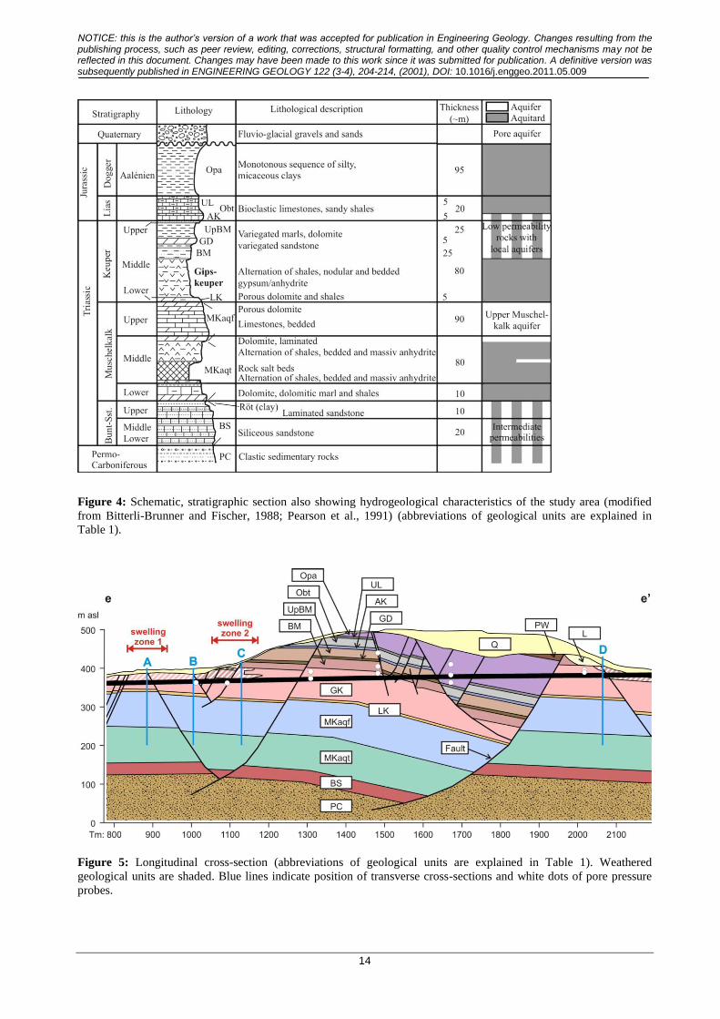
The Chienberg tunnel crosses, besides Quaternary sediments near the surface, Triassic and
Jurassic bedrock with a stratigraphic extent from the Opalinus Clay (top) to the Gipskeuper
(bottom). Below these strata, the Lettenkeuper and the Muschelkalk follow. Figure 4 shows a
schematic, stratigraphic and hydrogeological profile of the study area. The strata consist of
alternating shales and carbonate rocks with various hydraulic permeabilities. Large parts of the
tunnel are located within the Gipskeuper. This formation consists of a dark grey marlstone with
interbedded clay and dolomite layers. The Gipskeuper contains the calcium-sulfate minerals
anhydrite (CaSO4) and gypsum (CaSO4•2H2O), which appear as veins (gypsum only), lenses and
nodules, as well as dispersed in the rock matrix and as massive beds. In the upper parts of the
Gipskeuper strata, the sulfate minerals are present in the form of gypsum, and in the lower parts,
as anhydrite. An anhydrite level can thus be defined, separating the gypsum-bearing Gipskeuper
strata above the anhydrite level from the anhydrite-bearing Gipskeuper strata below the anhydrite
level.
[Figure 4 near here]
The Gipskeuper is weathered if it occurs close to the surface below Quaternary colluvium. The

NOTICE: this is the author’s version of a work that was accepted for publication in Engineering Geology. Changes resulting from the publishing process, such as peer review, editing, corrections, structural formatting, and other quality control mechanisms may not be reflected in this document. Changes may have been made to this work since it was submitted for publication. A definitive version was subsequently published in ENGINEERING GEOLOGY 122 (3-4), 204-214, (2001), DOI: 10.1016/j.enggeo.2011.05.009
4
weathered zone of the Gipskeuper is characterized by a leaching of the sulfate minerals (i.e.,
sulfate is dissolved) accompanied by rock softening, resulting in soil-like geotechnical properties
with low rock stability and a “crumbly” appearance. A gypsum karst may have developed in the
weathered Gipskeuper, providing preferential pathways for groundwater flow. During tunnel
excavation, water inflow from the weathered Gipskeuper into the tunnel has often been observed,
with flow rates up to 60 l/min at some places. The water present in the weathered Gipskeuper is
impounded by the underlying unweathered Gipskeuper, which acts as an aquitard. The weathered
Gipskeuper is commonly covered by Quaternary colluvium. In some cases, weathered marlstones
of the Bunte Mergel occur between the weathered Gipskeuper and the Quaternary. The rocks of
the Bunte Mergel are very similar to those of the Gipskeuper when weathered, and both units are
hardly distinguishable from each other in drill cuttings.
At the base of the Gipskeuper, the ~5 m thick Lettenkeuper, consisting of marl and dolomite, and
the ~90 m thick carbonate rock series of the Upper and Middle Muschelkalk (“Muschelkalk
aquifer” in Figure 4) follow. The latter is a regional karst aquifer, underlain by the marlstones of
the Middle Muschelkalk (“Muschelkalk aquitard” in Figure 4).
During construction and operation of the Chienberg tunnel, major problems occurred with
swelling clay-sulfate rocks of the Gipskeuper. There are two zones near the western tunnel
entrance subject to swelling (Figures 3 and 5): swelling zone 1 extends from tunnel meter (tm)
835 to tm 940, and swelling zone 2 from tm 1060 to tm 1170. Core samples taken after tunnel
excavation in swelling zone 2 showed recent growth of gypsum needles in fissures in the
immediate surroundings of the tunnel, while such features were typically lacking away from the
tunnel. This observation provides evidence for the transformation of anhydrite into gypsum being
a major swelling mechanism in the swelling zones of the test site. Already during construction, a
heave of about 1.5 m of the open floor was observed in swelling zone 2 after a three month lasting
interruption of the excavation (Figure 1). After the installation of the lining, heaves at the tunnel
invert totaling 128 mm in swelling zone 1 and 81 mm in swelling zone 2 have been measured,
before a deformable zone under the driving surface was successfully implemented to prevent
further heave of the road (Kovári and Chiaverio, 2007). Yet, the swelling process in the
deformable zone continues to date with heaves up to 575 mm measured within about two years. In
spite of a geologically similar situation, no swelling is observed between the swelling zones and
near the eastern tunnel entrance (c.f., Figure 5).
[Figure 5 and Table 1 near here]
2.2 Geological cross-sections
A longitudinal cross-section parallel to the tunnel axis was produced by the engineering
companies in charge of planning and conducting the construction. It is based on exploration
boreholes and geological evidence during excavation. It covers the part of the tunnel that was
mined underground from tm 458 to tm 2312 (E–E’ in Figure 3) and reaches from the ground
surface to the tunnel level. This cross-section was slightly modified for the present study to
account for borehole data added after completion of the tunnel. It was also extended to a depth of -
500 m above sea level (asl) in order to include groundwater circulation systems below the tunnel
in the modeling (see next section). A detail of the modified and extended longitudinal cross-
section (cross-section e in Figure 3) is shown in Figure 5.
In addition, four transverse cross-sections (Figure 6) were established perpendicular to the tunnel
axis. They extend 100 m to each side of the tunnel axis and reach to a depth of 200 m asl. They
were constructed using the same data that were used to construct the longitudinal cross section,

NOTICE: this is the author’s version of a work that was accepted for publication in Engineering Geology. Changes resulting from the publishing process, such as peer review, editing, corrections, structural formatting, and other quality control mechanisms may not be reflected in this document. Changes may have been made to this work since it was submitted for publication. A definitive version was subsequently published in ENGINEERING GEOLOGY 122 (3-4), 204-214, (2001), DOI: 10.1016/j.enggeo.2011.05.009
5
and using data from geological mapping (NAGRA/SGK, 1984). Cross-sections A and C show the
geological situation of swelling zones 1 and 2, respectively. They are located at tm 885 and tm
1130, where maximum swelling heaves have been measured. Cross-sections B and D (tm 1005
and tm 2065) show the geological situation of the zones with similar geological configuration as
in the swelling zones, but without observable swelling. The anhydrite level was determined at
cross-sections A to D based on geochemical analyses of samples taken from drill cores. This
anhydrite level is shown in Figure 6 as a horizontal line extending 10 m to each side of the tunnel
axis.
[Figure 6 near here]
2.3 Numerical groundwater models
Based on the longitudinal (Figure 5) and the transverse cross-sections (Figure 6), two-dimensional
finite-element groundwater models were developed. Figure 7 shows exemplarily the setup of the
groundwater model of transverse cross-section A. At the upper model boundary (ground surface),
the hydraulic head was specified as follows: In the longitudinal cross-section, contour lines of the
hydraulic head, measured with pore water pressure probes in some of the exploration boreholes
(c.f., Figure 5), were constructed. From these contour lines, the hydraulic head was extrapolated to
all nodes of the finite-element mesh at the ground surface. In the transverse cross-sections, the
head at the upper model boundary (ground surface) above the tunnel was taken from the
longitudinal cross-section and then interpolated to the nodes of the finite-element mesh at this
boundary, assuming a constant depth to water table (i.e., the difference between the elevation and
the hydraulic head of the upper model boundary is constant). All other model boundaries were
implemented as constant flux boundaries. The flux values were deduced from regional scale
groundwater models that were developed earlier (for information concerning the setup of these
regional scale groundwater models, please refer to Butscher et al. (2011)). This “downscaling of
boundary conditions” was accomplished to account for regional scale flow systems (Zijl, 1999).
[Figure 7 near here]
The tunnel is implemented in the groundwater models by a constant head boundary with the
hydraulic head corresponding to the elevation of the tunnel invert (longitudinal cross-section,
Figure 8) and of the tunnel perimeter (transverse cross-sections, Figures 9 to 12). This
specification is based on the assumption that tunnel excavation leads to atmospheric pressure at
the tunnel walls. An excavation damaged zone (EDZ) is expected to occur around tunnels (Tsang
et al., 2005). This zone is characterized by enhanced fracturing, induced by the excavation and
stress redistribution. The induced fractures may lead to a considerable increase in rock
permeability and provide the possibility for preferential flow. In the longitudinal profile, the EDZ
was implemented by increasing the hydraulic conductivity of the tunnel area. The hydraulic
conductivity was assumed to be 100 times the surrounding rock in zones within hard unweathered
rock where the tunnel was excavated by blasting, and 10 times in zones within weathered rock
where blasting was applied only occasionally for loosening (c.f., Table 1). In the transverse cross-
sections, the same assumptions regarding the increase in the hydraulic conductivity were made.
However, the EDZ was located in a zone around the tunnel being a few m thick, while the tunnel
boundary itself was assumed to be impermeable (no water flow within the tunnel, approximated
by a hydraulic conductivity of 1E-16 m/s in the tunnel zone). In the longitudinal cross-section, the
tunnel cannot be implemented as impermeable, because in the two-dimensional setup of the model
this would decouple the groundwater flow systems above the tunnel from those below.
Faults may contain highly fractured zones that provide preferential pathways for groundwater

NOTICE: this is the author’s version of a work that was accepted for publication in Engineering Geology. Changes resulting from the publishing process, such as peer review, editing, corrections, structural formatting, and other quality control mechanisms may not be reflected in this document. Changes may have been made to this work since it was submitted for publication. A definitive version was subsequently published in ENGINEERING GEOLOGY 122 (3-4), 204-214, (2001), DOI: 10.1016/j.enggeo.2011.05.009
6
flow (Caine et al., 1996). Evidence for preferential groundwater pathways in fault zones of the test
site is given by losses of drilling liquid in fault zones and lugeon tests conducted in exploration
bore holes. In the models of this study, the simplifying assumption was made that faults can be
represented by discrete features with a cross-sectional area of 1 m2 having an increased hydraulic
conductivity (1.0e-5 m/s) parallel to the faults’ orientation. Geological units containing alternating
beds with high and low hydraulic conductivity were assigned an anisotropy factor of 0.1, i.e., the
hydraulic conductivity is 10 times less in vertical than in horizontal direction (c.f., Table 1). For
Quaternary colluvium, an anisotropy factor of 0.2 was assumed.
The model of the longitudinal cross-section was calibrated by fitting the calculated hydraulic head
to the head measured with 12 pore water pressure probes in exploration boreholes before the
tunnel excavation (c.f., Figure 5). The calibration was conducted by varying the hydraulic
conductivity of the geological units, using the parameter estimation algorithm provided by the
code implemented in PEST (Doherty, 2005). The parameter estimation revealed plausible values
(c.f., Table 1) for the geological units (e.g. Delleur, 1999). However, the differences in estimated
hydraulic conductivity between the individual geological units are unexpectedly low. To cross-
check the plausibility of the calibration, the flux into the model area via the ground surface was
calculated. This flux corresponds to a groundwater recharge of 620 mm/a, which is in good
agreement to the value of ~600 mm/a given by the Hydrological Atlas of Switzerland (FOEN,
2010). The hydraulic conductivities estimated in the longitudinal cross-section model were
adopted in the transverse cross-section models.
The steady-state groundwater models calculate the distribution of the hydraulic head according to
the equations for confined, saturated groundwater flow provided by the software package
FEFLOW (Diersch, 2005). To assess the hydraulic changes induced by the tunneling, the
hydraulic head was calculated for each of the transverse cross-sections with and without tunnel.
The models without tunnel have no boundary conditions set at the tunnel, and no EDZ is
implemented in these models, i.e., the area of the tunnel has the same hydraulic properties as the
surrounding rock.
Particle tracking was conducted for each transverse cross-section with and without tunnel. The
line representing the anhydrite level in the transverse cross-sections has been chosen as starting
line for the particle tracking. 200 particles, evenly distributed on this line, were tracked backward
according to the hydraulic head field calculated with the models to show flowpaths towards the
anhydrite level. The basic idea behind this approach is to visualize the capture zone of the
anhydrite level at the investigated locations, before and after tunneling. It is based on the
assumption that swelling of the clay sulfate rocks is triggered if the hydraulic changes induced by
the tunneling lead to water access to the anhydrite-bearing strata of the Gipskeuper. Therefore, the
origin of water reaching the anhydrite level was of major interest in this study.
3. Results and Interpretation
In this section, the results of the numerical simulations are presented. The main part of this section
concentrates on the hydrogeological conditions at the position of the transverse cross-sections A to
D. The description of these conditions is accomplished (1) in terms of the geometrical relation
between the tunnel and the geological setting (i.e., the position of the tunnel relative to the
boundary weathered/unweathered Gipskeuper, the anhydrite level and the Quaternary cover), and
(2) in terms of flowpaths towards the anhydrite level before and after tunneling. The description of
the flowpaths includes the hydrogeological units that are passed by the groundwater flowing
towards the anhydrite level. At the end of this section, an interpretation of the results is given.

NOTICE: this is the author’s version of a work that was accepted for publication in Engineering Geology. Changes resulting from the publishing process, such as peer review, editing, corrections, structural formatting, and other quality control mechanisms may not be reflected in this document. Changes may have been made to this work since it was submitted for publication. A definitive version was subsequently published in ENGINEERING GEOLOGY 122 (3-4), 204-214, (2001), DOI: 10.1016/j.enggeo.2011.05.009
7
3.1 Longitudinal cross-section
Figure 8 shows the distribution of the hydraulic head calculated with the calibrated model of the
longitudinal cross-section before tunneling. This model was developed to estimate hydraulic
conductivities of the geological units by inverse calibration. The longitudinal cross-section model
was not used to assess the influence of tunneling on groundwater flow systems, because the
implementation of the tunnel as a constant head boundary, crossing the entire model domain,
would lead to a hydraulic decoupling of the area above from the area below the tunnel. The ability
of the 2D model to account for flow crossing the tunnel area in a realistic way would thus be
limited, and the validity of model results would be unreliable.
[Figure 8 near here]
3.2 Cross-section A (swelling zone 1)
In cross-section A (Figure 6, top left), the weathered Gipskeuper is covered by Quaternary
colluvium. The boundary layer weathered/unweathered Gipskeuper is located at the tunnel crown,
and the anhydrite level is situated ~2.0 m above the tunnel invert. In a geometrical sense, the
tunnel forms a “connection” between the weathered Gipskeuper and the anhydrite-bearing
Gipskeuper.
Flow towards the anhydrite level approaches from below before the tunnel excavation (Figure 9,
left). The capture zone includes the Muschelkalk aquifer, the Lettenkeuper and lower parts of the
Gipskeuper. Flowpaths are partly concentrated along a fault, which cuts through the strata close to
the tunnel. After tunnel excavation, groundwater flow towards the anhydrite level generally is
downward directed (Figure 9, right). The capture zone includes the weathered Gipskeuper and the
Quaternary cover. A concentration of flowpaths can be observed along the normal fault mentioned
above. Flowpaths are also concentrated in a narrow zone around the tunnel. This zone corresponds
to the EDZ with higher hydraulic conductivities in the model. Immediately next to the tunnel, the
anhydrite level receives groundwater from the weathered Gipskeuper at the crown of the tunnel.
[Figure 9 near here]
3.2 Cross-section B (between swelling zone 1 and 2, no observable swelling)
Also in cross-section B (Figure 6, top right), the weathered Gipskeuper is covered by Quaternary
colluvium. The boundary layer weathered/unweathered Gipskeuper is located ~4.3 m below the
tunnel crown. The anhydrite level is situated ~1.4 m below the tunnel invert. In this cross-section,
the anhydrite level is not “connected” to the weathered Gipskeuper by the tunnel.
Both before and after the tunnel excavation groundwater approaches the anhydrite level from
below (Figure 10). The capture zone includes the Muschelkalk aquifer, the Lettenkeuper and the
unweathered Gipskeuper. Just as in cross-section A, a concentration of flowpaths by faults can be
observed. Also after the tunnel excavation, there is no groundwater flow from the weathered
Gipskeuper or the Quaternary cover towards the anhydrite level.
[Figure 10 near here]
3.3 Cross-section C (swelling zone 2)
In cross-section C (Figure 6, bottom left), the weathered Gipskeuper is covered by weathered
Bunte Mergel and Quaternary colluvium (Note: During tunnel construction, a cave-in occurred.
The cave-in area above the tunnel is filled with loose material consisting of Gipskeuper, Bunte
Mergel and Quaternary rocks. The gallery left of the tunnel (c.f., Figures 6 and 11) was excavated

NOTICE: this is the author’s version of a work that was accepted for publication in Engineering Geology. Changes resulting from the publishing process, such as peer review, editing, corrections, structural formatting, and other quality control mechanisms may not be reflected in this document. Changes may have been made to this work since it was submitted for publication. A definitive version was subsequently published in ENGINEERING GEOLOGY 122 (3-4), 204-214, (2001), DOI: 10.1016/j.enggeo.2011.05.009
8
after the cave-in to explore and secure the cave-in area. It was then re-filled with material from the
tunnel excavation. Both zones were assigned the hydraulic properties of the Quaternary cover in
the models). The boundary layer weathered/unweathered Gipskeuper is located at the level of the
tunnel crown. The anhydrite level is situated ~5.5 m above the tunnel invert. Just as in cross-
section A, the weathered Gipskeuper is “connected” to the anhydrite level by the tunnel.
Flow towards the anhydrite level approaches from below before the tunnel excavation (Figure 11,
left). The capture zone includes, just as in cross-sections A and B, the Muschelkalk aquifer, the
Lettenkeuper and lower parts of the Gipskeuper. After the tunnel excavation, flow reaches the
anhydrite level from above (Figure 11, right), with groundwater originating from Quaternary
colluvium, the Bunte Mergel and the weathered Gipskeuper, partly crossing the cave-in area
above the tunnel. Flow paths are concentrated by faults and within the EDZ around the tunnel.
Just as in cross-section A, water from the weathered Gipskeuper at the tunnel crown is directed
around the tunnel in the EDZ towards the anhydrite level.
[Figure 11 near here]
3.4 Cross-section D (near the eastern tunnel entrance, no observable swelling)
In cross-section D (Figure 6, bottom right), the weathered Gipskeuper is covered by Quaternary
colluvium and landslide sediments. The boundary layer weathered/unweathered Gipskeuper is
located ~4.5 m above the tunnel crown. A second zone of weathered Gipskeuper, branching from
the weathered Gipskeuper to the east, intersects with the lower part of the tunnel (see also Figure
5). The anhydrite level is situated ~3.1 m below the tunnel invert. In this situation, the weathered
Gipskeuper is not “connected” to the anhydrite level by the tunnel.
Groundwater approaches the anhydrite level from below both before and after the tunnel
excavation (Figure 12). The capture zone includes the Muschelkalk aquifer, the Lettenkeuper and
the unweathered Gipskeuper. Also after the tunnel excavation, there is no groundwater flow from
the weathered Gipskeuper or Quaternary colluvium towards the anhydrite level. This situation
corresponds to the situation found in cross-section B.
[Figure 12 near here]
3.5 Interpretation
Before the tunnel excavation, the capture zones of the anhydrite level are situated in strata with
low hydraulic permeability close to the tunnel area. These strata prevent major water access to the
anhydrite level, and thus the transformation of anhydrite into gypsum. No swelling of the clay-
sulfate rocks is to be expected before the tunnel excavation.
After the tunnel excavation, the hydraulic situation in the subsurface has changed. The changes
lead in certain hydrogeological situations to water inflow at the anhydrite level from the
weathered Gipskeuper. The tunnel and the surrounding EDZ provide a “hydraulic short circuit”,
which connects the water reservoir that may be present in the weathered Gipskeuper with the
anhydrite level. This can be observed in cross-sections A and C, which are located in the swelling
zones. In contrast, no “hydraulic short circuit” between the weathered Gipskeuper and the
anhydrite level occurs at cross-sections B and D (the zones without observable swelling). The
hydraulic changes induced by the tunneling do not lead to a shift in flow directions towards the
anhydrite level, and the capture zones of the anhydrite level are still situated below the anhydrite
level. Hence, no water access to the anhydrite level is generated by the tunneling, and no swelling
is to be expected.

NOTICE: this is the author’s version of a work that was accepted for publication in Engineering Geology. Changes resulting from the publishing process, such as peer review, editing, corrections, structural formatting, and other quality control mechanisms may not be reflected in this document. Changes may have been made to this work since it was submitted for publication. A definitive version was subsequently published in ENGINEERING GEOLOGY 122 (3-4), 204-214, (2001), DOI: 10.1016/j.enggeo.2011.05.009
9
5. Discussion
In this study, the position of the boundary layer weathered/unweathered Gipskeuper and of the
anhydrite level relative to the position of the tunnel was determined. In addition, the hydraulic
changes in the subsurface induced by the tunneling was investigated using numerical groundwater
models. This was mainly accomplished by analyzing the capture zone of the anhydrite level, i.e.,
the flow paths towards the anhydrite level before and after the tunnel excavation.
The results suggest that the tunnel and the surrounding EDZ generate a “hydraulic short circuit” in
certain hydrogeological situations, connecting the water reservoir present in the weathered
Gipskeuper with the anhydrite level. The presence of water in the weathered Gipskeuper was often
observed during tunnel excavation (water inflow into the open tunnel during excavation). Before
tunneling, the unweathered Gipskeuper prevents the access of this water to the anhydrite level.
After tunnel excavation, the protective function of the low permeable Gipskeuper is damaged by
the tunnel and the EDZ, allowing water access to the anhydrite-bearing layers of the Gipskeuper.
The tunnel/EDZ is active as a “hydraulic short circuit” only in hydrogeological situations where
groundwater flow is downward directed (from the weathered Gipskeuper towards the anhydrite
level) after the tunneling.
There are several uncertainties concerning the model results. First of all, it is difficult to estimate
adequate boundary conditions. In this study, boundary conditions were deduced from regional
scale models (Butscher et al., 2011). At the regional scale, boundary conditions can be estimated
based on conceptual considerations. For example, it is reasonable to assume no flow conditions at
regional groundwater divides formed by major receiving streams (e.g., Hubbert, 1940; Freeze and
Witherspoon, 1967). At the local scale of the tunnel, in contrast, hydraulic data to estimate
boundary conditions are lacking. Another uncertainty concerns the hydraulic properties of the
geological units. These were estimated by inverse calibration of the longitudinal cross-section
model in this study. However, hydraulic data from the test site is limited, which is rather common
for tunneling projects. There were data from only 12 pressure probes available for this study, with
only three of them being close to the investigated sections. The change in hydraulic head as
calculated by the models was not documented by measurements, because the hydraulic head was
only measured before the tunnel excavation. Measuring the hydraulic head before and after
tunneling at different levels, also below the tunnel level, would be a major aid in assessing the
hydraulic changes induced by the tunnel. The problem of data scarcity also concerns other
hydraulic parameters, such as the hydraulic conductivities of the geological units and the EDZ.
Nevertheless, the modeling of the flow field before and after tunneling reveals possible processes
that can explain the observed swelling phenomena.
The findings of this study emphasize the role of the EDZ for the swelling process. The importance
of this zone is also suggested by field evidence: Rock swelling in the Chienberg tunnel started
immediately after the excavation. This means that water access to the clay-sulfate rocks must have
occurred rapidly. Given that groundwater flow is usually very slow in clay-sulfate rocks because
of their very low hydraulic conductivities, the increased permeability of this zone is a prerequisite
to provide the possibility for fast groundwater flow. There is little known about the actual
properties of the EDZ at the test site. Tsang et al. (2005) reported an increase in hydraulic
conductivities of up to 6 orders of magnitude and an extent of one drift radius for that zone within
indurated clays. These estimates are based on tests in Mont Terri (Switzerland) and Tournemire
(France) underground laboratories. However, the properties of the EDZ will depend on many
conditions, among others on the initial stress field, the material properties (e.g., material
anisotropy), the existence of natural fracture zones or local inhomogeneities of the rock mass and

NOTICE: this is the author’s version of a work that was accepted for publication in Engineering Geology. Changes resulting from the publishing process, such as peer review, editing, corrections, structural formatting, and other quality control mechanisms may not be reflected in this document. Changes may have been made to this work since it was submitted for publication. A definitive version was subsequently published in ENGINEERING GEOLOGY 122 (3-4), 204-214, (2001), DOI: 10.1016/j.enggeo.2011.05.009
10
the geometry of the tunnel (Blümling et al., 2007). Also the excavation method (e.g., blasting,
tunnel boring machine) plays an important role (Sato et al., 2000). If predictions are to be made
about the swelling risk at a certain location, the extent and hydraulic effectiveness of the EDZ
must be known. This information is essential to judge whether the EDZ may provide a hydraulic
connection between the weathered Gipskeuper (or other aquifers) and the anhydrite level, or not,
when these levels are in a certain distance of the tunnel and the EDZ.
A problem when planning engineering measures to prevent swelling is the unknown relation
between swelling heave and pressure for clay-sulfate rocks. Field and laboratory measurements
often give contradictory indications of the magnitude of swelling heave and pressure (Madsen and
Nüesch, 1991; Nüesch et al., 1995; Pimentel, 2007). A possible reason for this is that hydraulic
field conditions may not be adequately transferred to the laboratory. The simulations conducted in
this study may help to reveal relevant boundary conditions for swelling experiments and, by this,
can improve the investigation of mechanical and chemical processes involved in swelling in the
laboratory. In addition, the knowledge of the hydrogeological conditions at a certain site is an
essential prerequisite for the planning of remedial measures. For example, drainage galleries or
drainage boreholes may be a suitable measure to prevent water access to clay-sulfate rocks.
Predictions of the effectiveness of drainage devices, as well as the optimization of drainage
measures (e.g., optimal position of drainage elements with respect to the tunnel or swelling zone)
would be strongly supported by the presented approach.
There are some questions that remain open. For example, different orientations or three
dimensional (3D) models are required to account for the 3D nature of groundwater flow.
However, this would require a 3D exploration of the tunnel area, involving exploration boreholes
supported by geophysical exploration (e.g., seismics) not only at the position of the tunnel, but
also in its wider vicinity. The exploration efforts would thereby increase, but likely be
compensated by better adapted engineering strategies to counter the swelling problem.
In the swelling zones, water flow to the anhydrite level after tunnel excavation originates from the
weathered Gipskeuper in this study. However, rapid water access to the anhydrite level can also be
generated differently. For example, preferential flow along faults could bring water from the
underlying Muschelkalk aquifer to the anhydrite level. The hydraulic changes induced by the
tunneling may activate such preferential pathways for groundwater flow after the tunneling. Such
faults may be minor and not detectable from exploration boreholes before tunnel construction.
Therefore, it cannot be concluded from the present study if there are hydrogeological conditions
favoring rock swelling other than those identified in this study.
5. Conclusions
The aim of this study was to present an approach to estimate the swelling potential of clay-sulfate
rocks in tunnel engineering. The combined analysis of hydrogeological conditions and of
hydraulic changes induced by the tunneling suggests that the tunnel and the surrounding EDZ
provide a “hydraulic short circuit” that connects the water reservoir present in the weathered
Gipskeuper with the anhydrite level. The findings indicate a process that favors the transformation
of anhydrite into gypsum, and therefore is suited to trigger the swelling of clay-sulfate rocks in
tunnel engineering. The study also reveals the importance of a sound hydraulic data set to reduce
model uncertainties and to better judge the hydraulic effectiveness of the EDZ. The results of the
study may also contribute to improved swelling experiments in the laboratory and a more reliable
planning of remedial measures in tunnels that are damaged by rock swelling. The overall aim is to
improve the scientific basis for decisions made during planning, budgeting and execution of
tunnel projects in clay-sulfate rocks.

NOTICE: this is the author’s version of a work that was accepted for publication in Engineering Geology. Changes resulting from the publishing process, such as peer review, editing, corrections, structural formatting, and other quality control mechanisms may not be reflected in this document. Changes may have been made to this work since it was submitted for publication. A definitive version was subsequently published in ENGINEERING GEOLOGY 122 (3-4), 204-214, (2001), DOI: 10.1016/j.enggeo.2011.05.009
11
Acknowledgements
The authors thank the Tiefbauamt Basel-Landschaft (Cantonal Civil Engineering Office) for the
provision of geological, hydrological and geotechnical data and the three reviewers for their
helpful comments. This research was funded by the Swiss Federal Roads Office ASTRA (project
FGU 2008/5) and by a grant to C. Butscher from the Swiss National Science Foundation (SNF
grant no. PBBSP2-130955).
References
Anagnostou, G., 1992. Untersuchungen zur Statik des Tunnelbaus in quellfähigem Gebirge. PhD
thesis, ETH Zurich.
Anagnostou, G., Pimentel, E., Serafeimidis, K., 2010. Swelling of sulphatic claystones – some
fundamental questions and their practical relevance. Geomechanics and Tunnelling 3 (5),
567–572.
Bitterli-Brunner, P., Fischer, H., 1988. Explanations to geological map Blatt Arlesheim 1067 (in
German). Geological Atlas of Switzerland, Bern.
Blount, C.W., Dickson, F.W., 1973. Gypsum-anhydrite equilibria in the system CaSO4-H2O and
CaSO4-NaCI-H2O. American Mineralogist 58, 323–331.
Blümling, P., Bernier, F., Lebon, P., Martin, C.D., 2007. The excavation damaged zone in clay
formations – time-dependent behaviour and influence on performance assessment. Physics
and Chemistry of the Earth 32, 588–599.
Butscher, C., Huggenberger, P., Zechner, E., (2011): Impact of tunneling on regional groundwater
flow and implications for swelling of clay-sulfate rocks. Engineering Geology 117 (3-4),
198–206.
Caine, J.S., Evans, J.P., Forster, C.B., 1996. Fault zone architecture and permeability structure.
Geology 24 (11), 1025–1028.
Delleur, J.W. (Ed.), 1999. The handbook of groundwater engineering. CRC Press, Boca Raton
(FL), Springer, Heidelberg.
Diersch, H.-J.G. (Ed.), 2005. FEFLOW Finte Element Subsurface Flow and Transport Simulation
System – Reference manual. WASY Institute for Water Resources Planning and Systems
Research, Berlin.
Doherty, J., 2005. PEST – Model-Independent Parameter Estimation, User Manual: 5th Edition.
Watermark Numerical Computing, Brisbane.
Einstein, H.H., 1996. Tunnelling in difficult ground – Swelling behaviour and identification of
swelling rocks. Rock mechanics and rock engineering 29 (3), 113–124.
Flückiger, A., Nüesch, R., Madsen, F., 1994. Anhydritquellung. Berichte der Deutschen Ton- und
Tonmineralgruppe DTTG: Beiträge zur Jahrestagung 13–14 September 1994, Regensburg,
146–153.
FOEN (Ed.), 2010. Hydrological Atlas of Switzerland. Swiss Federal Office for the Environment
(FOEN), Bern.
Freeze, R.A., Witherspoon, P.A., 1967. Theroretical analysis of regional froundwater flow. 2.
Effect of water-table configuration and subsurface permeability variation. Water
Resources Research 3 (2), 623–634.
Hauber, L., Jordan, P., Madsen, F., Nüesch, R., Vögtli, B., 2005. Clay minerals and sulfates as
source of swelling of sediments. Reasons and effects of swelling. Final report of research
projects 55/92 and 52/96. Swiss Federal Roads Office (ASTRA), Bern.
Hubbert, M.K., 1940. The theory of ground-water motion. Journal of Geology 48 (8), 785–944.
Kovári, K., Chiaverio, F., 2007. Modular yielding support for tunnels in heavily swelling rock.
Preprint STUVA Conference 07, 26–29 November 2007, Köln.
Madsen, F.T., Nüesch R., 1991. The swelling behaviour of clay-sulphate rocks. 7th Internat.
Congress on Rock Mechanics, September 1991, Aachen, 263–267.

NOTICE: this is the author’s version of a work that was accepted for publication in Engineering Geology. Changes resulting from the publishing process, such as peer review, editing, corrections, structural formatting, and other quality control mechanisms may not be reflected in this document. Changes may have been made to this work since it was submitted for publication. A definitive version was subsequently published in ENGINEERING GEOLOGY 122 (3-4), 204-214, (2001), DOI: 10.1016/j.enggeo.2011.05.009
12
NAGRA/SGK (Eds.), 1984. Geologische Karte der zentralen Nordschweiz 1:100'000 mit
angrenzenden Gebieten von Baden-Württtemberg. Nationale Genossenschaft für die
Lagerung radioaktiver Abfälle (NAGRA), Wettingen, and Schweizerische Geologische
Kommission (SGK), Bern.
Nüesch, R., Steiner, W., Madsen, F.T., 1995. Long time swelling of anhydritic rocks:
mineralogical and microstructural evaluation. 8th Internat. Congress on Rock Mechanics,
25–30 September 1995, Tokyo, 285–288.
Pearson, F.J., Balderer, W., Loosli, H.H., Lehmann, B.E., Matter, A., Peters, T., Schmassmann,
H., Gautschi, A., 1991. Applied Isotope Hydrogeology – a case study in northern
Switzerland. Elsevier, Amsterdam.
Pierau, B., Kiehl, J.R., 1996. Widerstands- und Ausweichprinzip: Vergleich zweier
Entwurfsmethoden für Tunnelbauten in quellfähigem Gebirge. Taschenbuch für den
Tunnelbau 1996, Verlag Glückauf GmbH, Essen.
Pimentel, E., 2007. A laboratory testing technique and a model for the swelling behavior of
anhydritic rock. 11th Congress of the International Society for Rock Mechanics, 9–13 July
2007, Lisbon, 143–146.
Ping, X., Beaudoin, J., 1992. Mechanism of sulphate expansion. Cement and concrete research 22,
631–640.
Sato, T., Kikuchi, T., Sugihara, K., 2000. In-situ experiments on an excavation disturbed zone
induced by mechanical excavation in Neogene sedimentary rock at Tono mine, central
Japan. Engineering Geology 56, 97–108.
Steiner, W., 1993. Swelling rock in tunnels: Characterization, effect of horizontal stresses and
Construction Procedures. International Journal of Rock Mechanics & Mining Sciences &
Geomechanical Abstracts 30 (4), 361–380.
Tsang, C.F., Bernier, F., Davies, C., 2005. Geohydromechanical processes in the Excavation
Damaged Zone in crystalline rock, rock salt, and indurated and plastic clays - in the
context of radioactive waste disposal. International Journal of Rock Mechanics & Mining
Sciences 42 (1), 109–125.
Zijl, W., 1999. Scale aspects of groundwater flow and transport systems. Hydrogeology Journal 7
(1), 139–150.
Figures
Figure 1: Floor heave in the Chienberg road tunnel during construction. During an interruption of the excavation
works, the floor of the top heading experienced a heave of about 1.5 m within three months. Photo courtesy of
Aegerter & Bosshardt AG, Basel.

NOTICE: this is the author’s version of a work that was accepted for publication in Engineering Geology. Changes resulting from the publishing process, such as peer review, editing, corrections, structural formatting, and other quality control mechanisms may not be reflected in this document. Changes may have been made to this work since it was submitted for publication. A definitive version was subsequently published in ENGINEERING GEOLOGY 122 (3-4), 204-214, (2001), DOI: 10.1016/j.enggeo.2011.05.009
13
Figure 2: Scetch of deformable zone in the Chienberg tunnel to prevent heave of road surface (from: Kovári and
Chiaverio, 2007).
Figure 3: Location of study site and cross-sections.
NOTICE: this is the author’s version of a work that was accepted for publication in Engineering Geology. Changes resulting from the publishing process, such as peer review, editing, corrections, structural formatting, and other quality control mechanisms may not be reflected in this document. Changes may have been made to this work since it was submitted for publication. A definitive version was subsequently published in ENGINEERING GEOLOGY 122 (3-4), 204-214, (2001), DOI: 10.1016/j.enggeo.2011.05.009
14
Figure 4: Schematic, stratigraphic section also showing hydrogeological characteristics of the study area (modified
from Bitterli-Brunner and Fischer, 1988; Pearson et al., 1991) (abbreviations of geological units are explained in
Table 1).
Figure 5: Longitudinal cross-section (abbreviations of geological units are explained in Table 1). Weathered
geological units are shaded. Blue lines indicate position of transverse cross-sections and white dots of pore pressure
probes.

NOTICE: this is the author’s version of a work that was accepted for publication in Engineering Geology. Changes resulting from the publishing process, such as peer review, editing, corrections, structural formatting, and other quality control mechanisms may not be reflected in this document. Changes may have been made to this work since it was submitted for publication. A definitive version was subsequently published in ENGINEERING GEOLOGY 122 (3-4), 204-214, (2001), DOI: 10.1016/j.enggeo.2011.05.009
15
Figure 6: Transverse cross-sections (abbreviations of geological units are explained in Table 1). Black lines indicate
exploration drill holes. Dots indicate sulfate analysis samples (green: sulfate present as gypsum, red: sulfate present as
anhydrite, orange: sulfate present as gypsum and anhydrite). Red line indicates anhydrite level. Dotted area in section
C represents a cave-in area. Question marks indicate the uncertain position of the boundary layer
weathered/unweathered Gipskeuper away from tunnel.

NOTICE: this is the author’s version of a work that was accepted for publication in Engineering Geology. Changes resulting from the publishing process, such as peer review, editing, corrections, structural formatting, and other quality control mechanisms may not be reflected in this document. Changes may have been made to this work since it was submitted for publication. A definitive version was subsequently published in ENGINEERING GEOLOGY 122 (3-4), 204-214, (2001), DOI: 10.1016/j.enggeo.2011.05.009
16
Figure 7: Setup of groundwater model of transverse cross-section A (abbreviations of geological units and their
hydraulic properties are explained in Table 1).
Figure 8: Modeled hydraulic head in longitudinal cross-section before tunneling (abbreviations of geological units are
explained in Table 1). Note: The high gradients occurring in the upper left part of the model are due to the constant
flux (2nd
kind) boundary condition in combination with the very low permeability of the Opalinus Clay formation. The
effects of the high gradients on the flow field outside the Opalinus Clay formation at this boundary are minor.

NOTICE: this is the author’s version of a work that was accepted for publication in Engineering Geology. Changes resulting from the publishing process, such as peer review, editing, corrections, structural formatting, and other quality control mechanisms may not be reflected in this document. Changes may have been made to this work since it was submitted for publication. A definitive version was subsequently published in ENGINEERING GEOLOGY 122 (3-4), 204-214, (2001), DOI: 10.1016/j.enggeo.2011.05.009
17
Figure 9: Modeled hydraulic head and flow paths towards anhydrite level in cross-section A before (left) and after
tunneling (right). The weathered Gipskeuper is indicated in grey with a dotted signature, other weathered bedrock and
Quaternary colluvium in white with a dotted signature. After tunnel excavation, the anhydrite level is hydraulically
connected to the weathered Gipskeuper by the tunnel and the surrounding EDZ.
Figure 10: Modeled hydraulic head and flow paths towards anhydrite level in cross-section B before (left) and after
tunneling (right). The weathered Gipskeuper is indicated in grey with a dotted signature, other weathered bedrock and
Quaternary colluvium in white with a dotted signature. Groundwater flow approaches the anhydrite level from below
both before and after tunneling.

NOTICE: this is the author’s version of a work that was accepted for publication in Engineering Geology. Changes resulting from the publishing process, such as peer review, editing, corrections, structural formatting, and other quality control mechanisms may not be reflected in this document. Changes may have been made to this work since it was submitted for publication. A definitive version was subsequently published in ENGINEERING GEOLOGY 122 (3-4), 204-214, (2001), DOI: 10.1016/j.enggeo.2011.05.009
18
Figure 11: Modeled hydraulic head and flow paths towards anhydrite level in cross-section C before (left) and after
tunneling (right). The weathered Gipskeuper is indicated in grey with a dotted signature, other weathered bedrock and
Quaternary colluvium in white with a dotted signature. After tunnel excavation, the anhydrite level is hydraulically
connected to the weathered Gipskeuper by the tunnel and the surrounding EDZ.
Figure 12: Modeled hydraulic head and flow paths towards anhydrite level in cross-section D before (left) and after
tunneling (right). The weathered Gipskeuper is indicated in grey with a dotted signature, other weathered bedrock and
Quaternary colluvium in white with a dotted signature. Groundwater flow approaches the anhydrite level from below
both before and after tunneling.

NOTICE: this is the author’s version of a work that was accepted for publication in Engineering Geology. Changes resulting from the publishing process, such as peer review, editing, corrections, structural formatting, and other quality control mechanisms may not be reflected in this document. Changes may have been made to this work since it was submitted for publication. A definitive version was subsequently published in ENGINEERING GEOLOGY 122 (3-4), 204-214, (2001), DOI: 10.1016/j.enggeo.2011.05.009
19
Tables
Table 1: Hydraulic model properties of geological units and structures.
Geolological unit
Symbol
Thickness
(m) Hydraulic conductivity
(m/s) Anisotropy
(k-vert./k-horiz.)
Quaternary
Landslide sediments
Passwang Formation
Opalinus Clay
Upper Lias
Obtusus Clay
Arietenkalk
Upper Bunte Mergel
Upper Bunte Mergel, weathered
Gansinger Dolomite
Gansinger Dolomite, weathered
Bunte Mergel
Bunte Mergel, weathered
Gipskeuper
Gipskeuper, weathered
Lettenkeuper
Muschelkalk aquifer
Muschelkalk aquitard
Buntsandstein
Permo-Carboniferous
Fault
Tunnel (longitudinal cross-section)
Tunnel (transverse cross-sections)
EDZ (no blasting)
EDZ (loosening blasting)
EDZ (excavation blasting)
Q
L
PW
Opa
UL
Obt
AK
UpBM
UpBMw
GD
GDw
BM
BMw
GK
GKw
LK
MKaqf
MKaqt
BS
PC
-
-
-
-
-
-
-
-
80
95
5
20
5
25
-
5
-
25
-
80
-
5
90
90
30
-
1
-
-
-
-
-
5.00E-07
5.00E-07
1.00E-06
1.00E-09
1.00E-06
1.00E-07
1.00E-06
1.00E-07
1.00E-07
1.00E-06
1.00E-07
1.00E-07
1.00E-07
1.00E-07
1.00E-07
1.00E-06
1.00E-06
1.00E-07
1.00E-06
1.00E-07
1.00E-05
as geol. unit
1.00E-16
as geol. unit
geol. unit x10
geol. unit x100
0.2
0.2
0.1
1
0.1
1
1
1
1
0.1
1
1
1
1
1
0.1
1
1
0.1
1
(fault parallel)
1
1
1
1
1