relay based traffic control system using infrared …ethesis.nitrkl.ac.in/3836/2/final_doc.pdf ·...
TRANSCRIPT

RELAY BASED TRAFFIC CONTROL SYSTEM USING
INFRARED PAIR DETECTORS
A PROJECT REPORT SUBMITTED IN THE PARTIAL FULFILLMENT
OF THE REQUIREMENT FOR THE DEGREE OF
Bachelor of Technology
in
Electronics & Communication Engineering
by
SAMBIT DASH -- 108EI003
MUKESH KUMAR – 108EC022
Department of Electronics & Communication Engineering
National Institute of Technology
Rourkela
2011-2012

RELAY BASED TRAFFIC CONTROL SYSTEM USING
INFRARED PAIR DETECTORS
A PROJECT REPORT SUBMITTED IN THE PARTIAL FULFILLMENT
OF THE REQUIREMENT FOR THE DEGREE OF
Bachelor of Technology
in
Electronics & Communication Engineering
by
SAMBIT DASH – 108EI003
MUKESH KUMAR – 108EC022
Under the Guidance of
Prof S.K.Das
Department of Electronics & Communication Engineering
National Institute of Technology
Rourkela
2011-2012

i
National Institute of Technology, Rourkela
CERTIFICATE
This is to certify that the thesis entitled “RELAY BASED TRAFFIC CONTOL
SYSTEM USING INFRARED PAIR DETECTORS” submitted by Sambit Dash &
Mukesh Kumar in the partial fulfilment of the requirement for the award of BACHELOR
OF TECHNOLOGY Degree in Electronics & Communication Engineering at the National
Institute of Technology, Rourkela (Deemed University) is an authentic work carried out by
them under my supervision and guidance.
To the best of my knowledge, the matter embodied in the thesis has not been submitted to any
other University/ Institute for the award of any degree or diploma.
Prof S.K.Das
Date: 5th May, 2012 Department of Electronics & Communication Engineering
National Institute of Technology
Rourkela - 769008

ii
ACKNOWLEDGEMENT
I avail this opportunity to express my indebtedness to my guide Prof. S.K.Das, Electronics &
Communication Engineering Department, National Institute of Technology, Rourkela, for his
valuable guidance, constant encouragement and kind help at various stages for the execution
this dissertation work. An erudite teacher, a magnificent person and a strict disciplinarian, I
consider myself fortunate to have worked under his supervision.
I also express my sincere gratitude to Prof. S.Meher, Head of The Department, Prof.
K.K.Mohapatra & Prof S.K.Patra, Department of Electronics & Communication
Engineering at NIT Rourkela for providing valuable department facilities.
I am also highly indebted to my friends Gigyanshu,Amit and Deepankar for helping us in
achieving of the targets of the project.
Submitted By:
Sambit Dash -108EI003
Mukesh Kumar – 108EC022
Department of Electronics & Communication Engineering-----+
National Institute Of Technology, Rourkela
Rourkela-769008

iii
ABSTRACT
A relay is usually an electromechanical device that is actuated by an electrical current. The
current flowing in one circuit causes the opening or closing of another circuit. The IR sensor
pair typically consists of an IR transmitter and receiver pair. The IR transmitter is an led that
emits light in the infrared region of light spectrum. The IR receiver is a diode constructed in
such a way that when the diode is reverse biased ,their light falling on the depleted region
causes creation of electron-hole pair and thus this generated pair constitutes current. In our
project traffic control system is a simple adaptive controller which will adapt according to
amount of traffic in one direction. The system consists of 2 8 channel relay boards whose
switching will be controlled by the instructions embedded in the Atmega32 controller. In
every direction the road will consist of an IR transmitter-receiver pair at a certain distance
from traffic lights. When the traffic will be heavy in one particular direction during
emergency situations it will increase the time duration for that particular road.
Keywords: Traffic Control, Adaptive System, Relay Switching Principle, IR Sensor

iv
CONTENTS
Certificate I
Acknowledgement II
Abstract III
Contents IV
List of Figures VI
Chapter-1 Introduction 1
1.1 Introduction 2
1.2 Problem Definition 2
1.3 Objective 2
1.4 Project Scope 2
1.5 Thesis Outline 3
Chapter-2 Literature Review 4
2.1
Basics Of Traffic Control System
5
2.2 Relay 5
2.2.1 Types Of Relay 6
v
2.3 Relay Board 8
2.3.1 Specifications 10
2.4 IR Sensor 12
2.5 Atmega32 16
Chapter 3
System Hardware & Code
22
3.1 Introduction 23
3.2 Traffic Light Model 23
3.3 Code 24
Chapter 4 Results & Discussions 20
4.1
Prototype
31
4.2 Project Operation 31
4.3 Emergency Status ON 33
4.4 Advantages 35
Chapter 5
Conclusion & References
36
5.1
Conclusion
37
5.2 Recommendations 37
5.3 References 38

vi
LIST OF FIGURES
Fig2.1 Simple Relay Circuit 6
Fig2.2 Electromechanical Relay 7 Fig2.3 Solid State Relay 7
Fig2.4 Solid State Relay Circuit 8
Fig2.5 8-channel Relay Board 9
Fig2.6 Circuit Description of 8-channel Relay Board 10
Fig2.7 Schematic Of Relay Board 11 Fig2.8 Typical Tx/Rx 12
Fig2.9 Typical Transmitter Circuit 13
Fig2.10 Tx-Rx Pair Circuit 14
Fig2.11 PIN Configuration of LM324 15
Fig2.12 Atmega32 Development Board 17 Fig2.13 Atmega32 PIN Configuration 18

1
Chapter – 01
INTRODUCTION
2
1.1 INTRODUCTION:-
A traffic light is a collection of two or more coloured lights found at some junctions and
pedestrian crossings which indicates whether it is safe and/or legal to continue across the path
of other road users.
The operation of standard traffic lights which are currently deployed in many junctions, are
based on predetermined timing schemes, which are fixed during the installation and remain
until further resetting. The timing is no more than a default setup to control what may be
considered as normal traffic. Although every road junction by necessity requires different
traffic light timing setup, many existing systems operate with an over-simplified sequence.
This has instigated various ideas and scenarios to solve the traffic problem.
To design an intelligent and efficient traffic control system, a number of parameters that
represent the status of the road conditions must be identified and taken into consideration.
1.2 Problem Definition
The aim of this project is to design traffic control system that could minimize the waiting
time of the vehicles at intersections, when the traffic volume is significantly high.
1.3 Objectives of Project
1. To understand the relay working principle
2. To understand how to make the interfacing between relay board and microcontroller
3. To design a program that works together with a model of four- junction traffic light and
sensors.
4. To build the model of four-junctions of simple adaptive traffic light that can overcome the
problems of traffic light congestion.
1.4 Project Scope
1. Construct a model of four way junction of a traffic light model.
2. Programme the microcontroller to control the traffic light.
3. Combine the software part and the hardware part to simulate a traffic light system.

3
1.5 Thesis Outline
Chapter 1 is the introduction to traffic light systems. This chapter also explains about project
objectives and scopes and discuss about problem statement.
Chapter 2 will describe all techniques, the theory of different components required for our
project.
Chapter 3 focuses on the system hardware & software implementation of traffic light control
system.
Chapter 4 deals with results and discussions regarding the project.
Chapter 5 with the conclusions and future recommendations about the project.

4
Chapter – 02
LITERATURE REVIEW

5
Traffic signals are the most convenient method of controlling traffic in a busy junction. But,
we can see that these signals fail to control the traffic effectively when a particular lane has
got more traffic than the other lanes. This situation makes that particular lane more crowded
with the vehicles than the other lanes. If the traffic signals can allot different time slots to
different lanes according to the traffic present in each lane, then, this problem can be solved
easily.
2.1 The Basics of Traffic lights
The most basic traffic light consists of three bulbs with different coloured lenses, which from
top to bottom are red, yellow and green.
1. Red— this indicates that traffic must stop behind the line. It is compulsory for all road users
to do so. Some traffic lights even have cameras to catch drivers breaking this law.
2. Yellow— this combination of bulbs indicates that the lights are about to change to green, and
gives drivers time to release their handbrake and prepare to drive off as soon as they are
allowed to do so.
3. Green— this indicates that traffic may pass through the junction, provided that it is safe to do
so and the way is clear.
2.2 RELAY:-
A relay is an electromechanical device that is actuated by an electrical current.
The current flowing in one circuit causes the opening or closing of another
circuit. Highly sophisticated relays are utilized to protect electric power
systems against trouble and power blackouts as well as to regulate and control
the generation and distribution of power. In the home, relays are used in
different appliances like refrigerators, washing machines and dishwashers, and
heating and air-conditioning controls. Every relay contains a sensing unit, the
electric coil, which is powered by AC or DC current. When the applied current
or voltage exceeds a threshold value, the coil activates the armature, which
operates either to close the open contacts or to open the closed contacts. When
a power is supplied to the coil, it generates a magnetic force that actuates the
6
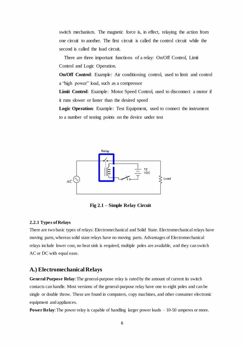
switch mechanism. The magnetic force is, in effect, relaying the action from
one circuit to another. The first circuit is called the control circuit while the
second is called the load circuit.
There are three important functions of a relay: On/Off Control, Limit
Control and Logic Operation.
On/Off Control: Example: Air conditioning control, used to limit and control
a “high power” load, such as a compressor
Limit Control: Example: Motor Speed Control, used to disconnect a motor if
it runs slower or faster than the desired speed
Logic Operation: Example: Test Equipment, used to connect the instrument
to a number of testing points on the device under test
Fig 2.1 – Simple Relay Circuit
2.2.1 Types of Relays
There are two basic types of relays: Electromechanical and Solid State. Electromechanical relays have
moving parts, whereas solid state relays have no moving parts. Advantages of Electromechanical
relays include lower cost, no heat sink is required, multiple poles are available, and they can switch
AC or DC with equal ease.
A.) Electromechanical Relays
General Purpose Relay: The general-purpose relay is rated by the amount of current its switch
contacts can handle. Most versions of the general-purpose relay have one to eight poles and can be
single or double throw. These are found in computers, copy machines, and other consumer electronic
equipment and appliances.
Power Relay: The power relay is capable of handling larger power loads – 10-50 amperes or more.

7
They are usually single-pole or double-pole units.
Contractor: A special type of high power relay, it’s used mainly to control high voltages and currents
in industrial electrical applications. Because of these high power requirements, contactors always
have double-make contacts.
Time-Delay Relay: The contacts might not open or close until sometime interval after the coil has
been energized. This is called delay-on-operate. Delay-on-release means that the contacts will remain
in their actuated position until some interval after the power has been removed from the coil. A third
delay is called interval timing. Contacts revert to their alternate position at a specific interval of time
after the coil has been energized. The timing of these actions may be a fixed parameter of the relay, or
adjusted by a knob on the relay itself, or remotely adjusted through an external circuit.
Fig 2.2:- Electromechanical Relay
B.) Solid State Relays:-
These active semiconductor devices use light instead of magnetism to actuate a switch. The light
comes from an LED, or light emitting diode. When control power is applied to the device’s
output, the light General Purpose Relay is turned on and shines across an open space. On the load side
of this space, a part of the device senses the presence of the light, and triggers a solid state switch that
either opens or closes the circuit under control. Often, solid state relays are used where the circuit
under control must be protected
Fig 2.3:- Solid State Relay

8
Fig 2.4:- Solid state Relay Circuit
Contact Information
The contacts are the most important parts of a relay. Their characteristics are significantly
affected by factors such as the material of the contacts, voltage and current values applied to
them (especially, the voltage and current waveforms when energizing and de-energizing the
contacts), the type of load, operating frequency, and bounce. If any of these factors fail to
satisfy a predetermined value, problems such as metal degradation between contacts, contact
welding, wear, or a rapid increase in the contact resistance may occur. The quantity of
electrical current that flows through the contacts directly influences the contacts’
characteristics. For example, when the relay is used to control an inductive load, such as a
motor of a lamp. The contacts will wear faster and metal decomposition between the mating
contacts will occur more often as the inrush current to the contacts increases.
2.3 RELAY BOARD: - The relay board is what powers the switching mechanics on your
electronic devices. It contains a power supply circuit, regulatory circuitry and of course the
relays that you need to turn parts or all of your device (or devices) on and off – or to switch
them between states. Normally speaking, the relays on your relay board will be solid state,
unlike the mechanical relays that you may see in larger electrical applications (like, for
example, the switch you throw to turn off a phased power relay, or the breakers in your
home’s circuitry). Solid state relays are reliable over a longer term than electro mechanical
relays thanks to the simple fact that they have no moving parts (hence the name solid state),
which means of course that nothing can seize up or break off and prevent successful operation.
The SSR on your relay board will contain a transistor or a number of transistors, through
which the switch of state is made.
Early solid state relays suffered a drop in voltage across their transistors, but modern SSRs

9
are capable of carrying switching loads with much higher currents. The terminology with
which one’s relay board will be described and/or discussed in manuals, advice and literature is
the same terminology that you will find for the discussion of any electronic or electric
switches. The basic function of the relays on your relay board is to flick between one or
several poles. This is done by throwing contacts between them (“pole” and “throw” are the
electrical switching terms we’re interested in here). Most of the terminology describing the
state of the contacts in your relay board is compressed into acronymic form: NO (Normally
Open); NC (Normally Closed); and Change Over or Double Throw (referred to either as CO
or DT, both of which mean the same thing).
A Normally Open contact is one that is usually disconnected – so in its resting or inactive
state the contact is open. A Normally Closed contact has the opposite characteristic: in its
resting state the circuit is connected and active because the relay has closed on the contact. A
Change Over or Double Throw contact connects two linked circuits – one Normally Open and
the other Normally Closed. The switch on your relay board throws the pole between the
Normally Open and the Normally Closed circuit when the switch is activated. The functions of
the switches on your relay board depend (naturally) on your application. In general terms they
are commonly used to increase power where there is a weak power source (amplification,
usually of a signal); to isolate a controlled and controlling circuit from each other; to switch to
a standby power state; to implement a time delay; or to control logic within your electronic
circuitry. A series of Normally Open contacts on a relay board is equal to AND; a parallel
connection of Normally Open contacts becomes OR.
Fig 2.5:- 8-Channel Relay Board
10
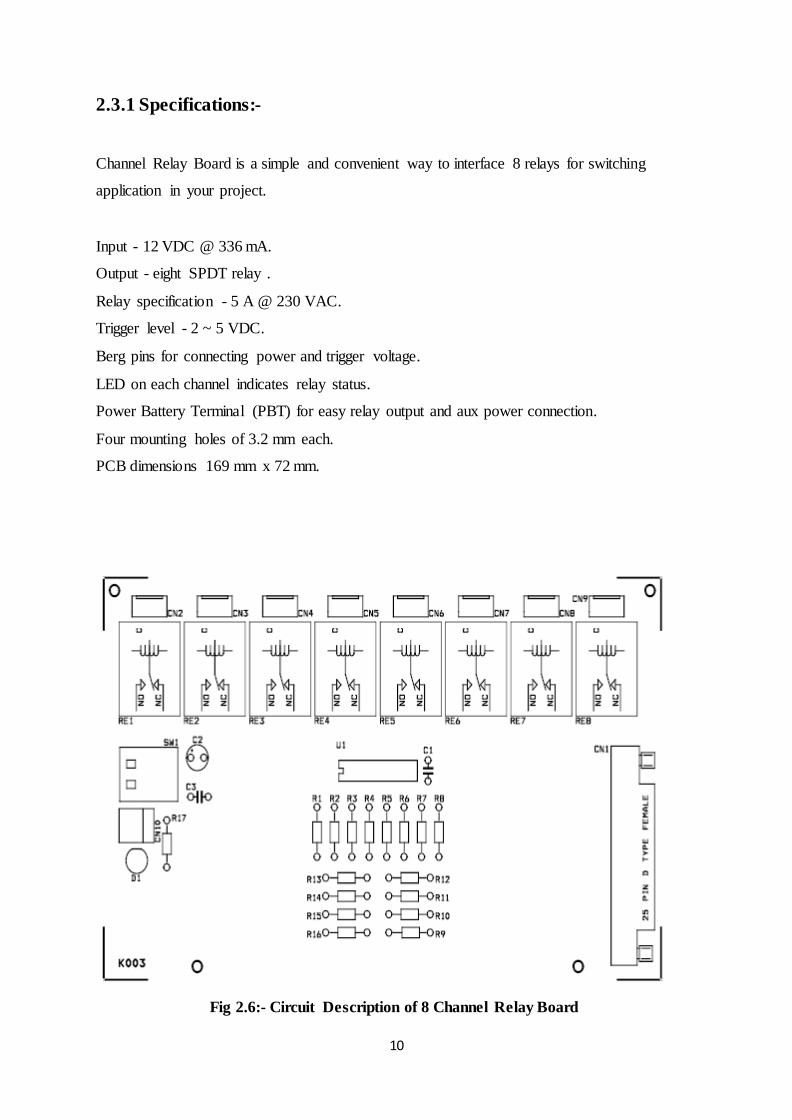
2.3.1 Specifications:-
Channel Relay Board is a simple and convenient way to interface 8 relays for switching
application in your project.
Input - 12 VDC @ 336 mA.
Output - eight SPDT relay .
Relay specification - 5 A @ 230 VAC.
Trigger level - 2 ~ 5 VDC.
Berg pins for connecting power and trigger voltage.
LED on each channel indicates relay status.
Power Battery Terminal (PBT) for easy relay output and aux power connection.
Four mounting holes of 3.2 mm each.
PCB dimensions 169 mm x 72 mm.
Fig 2.6:- Circuit Description of 8 Channel Relay Board

11
Fig 2.7 Schematic Of Relay Board

12
2.4 IR SENSOR :-
Infrared sensors are in the form of diodes with 2 terminals. One can
buy a pair of such diode (one transmitter and one receiver) at a very low cost of about 5 -
7 rupees only. Tx refers to a transmitter and Rx refers to a receiver diode.
Fig 2.8:- Typical Tx/Rx
Upon careful observation, one will notice that amongst the two ‘legs’,
one has a much wider base within the diode. This is normally the cathode (negative) whereas
the leg having a smaller base would be the anode (positive terminal).
Operation:
When the Tx is forward biased, it begins emitting infrared. Since it’s not in visible spectrum,
you will not be able to see it through naked eyes but you will be able to view it through an
ordinary cell phone camera.
13
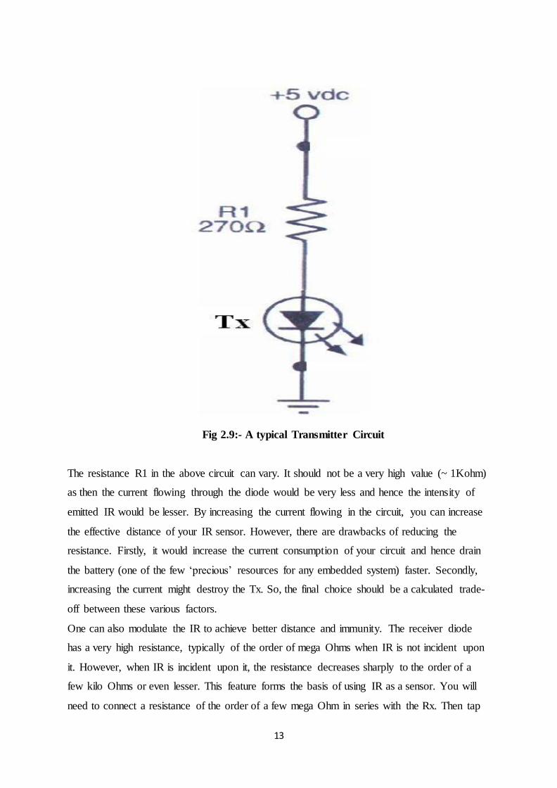
Fig 2.9:- A typical Transmitter Circuit
The resistance R1 in the above circuit can vary. It should not be a very high value (~ 1Kohm)
as then the current flowing through the diode would be very less and hence the intensity of
emitted IR would be lesser. By increasing the current flowing in the circuit, you can increase
the effective distance of your IR sensor. However, there are drawbacks of reducing the
resistance. Firstly, it would increase the current consumption of your circuit and hence drain
the battery (one of the few ‘precious’ resources for any embedded system) faster. Secondly,
increasing the current might destroy the Tx. So, the final choice should be a calculated trade-
off between these various factors.
One can also modulate the IR to achieve better distance and immunity. The receiver diode
has a very high resistance, typically of the order of mega Ohms when IR is not incident upon
it. However, when IR is incident upon it, the resistance decreases sharply to the order of a
few kilo Ohms or even lesser. This feature forms the basis of using IR as a sensor. You will
need to connect a resistance of the order of a few mega Ohm in series with the Rx. Then tap

14
the output voltage at the point of connectivity of these two resistors. A complete Tx-Rx
circuit is given below.
Fig 2.10:- Tx-Rx Pair Circuitry
The output voltage is in the form of analog voltage. One needs to convert it into digital
format so that whenever IR is incident upon the Rx, the final conditioned output voltage is a
logic high (binary 1) and whenever IR is not incident upon the Rx, the conditioned output
voltage should be a logic low (binary 0).
One can use a comparator IC to serve this purpose. A comparator IC compares 2 input
voltages using an op-amp and gives logic high or a logic low as the final output. LM324 is
one such comparator.
Case1: when IR is not incident upon the Rx.
When the IR Tx is above a black line, the black line will absorb all the IR and will not reflect
an appreciable amount of IR for the Rx to receive. If you are making an obstacle avoiding
robot, then when there is no obstacle in front of the IR Tx, Rx will not receive back the
15
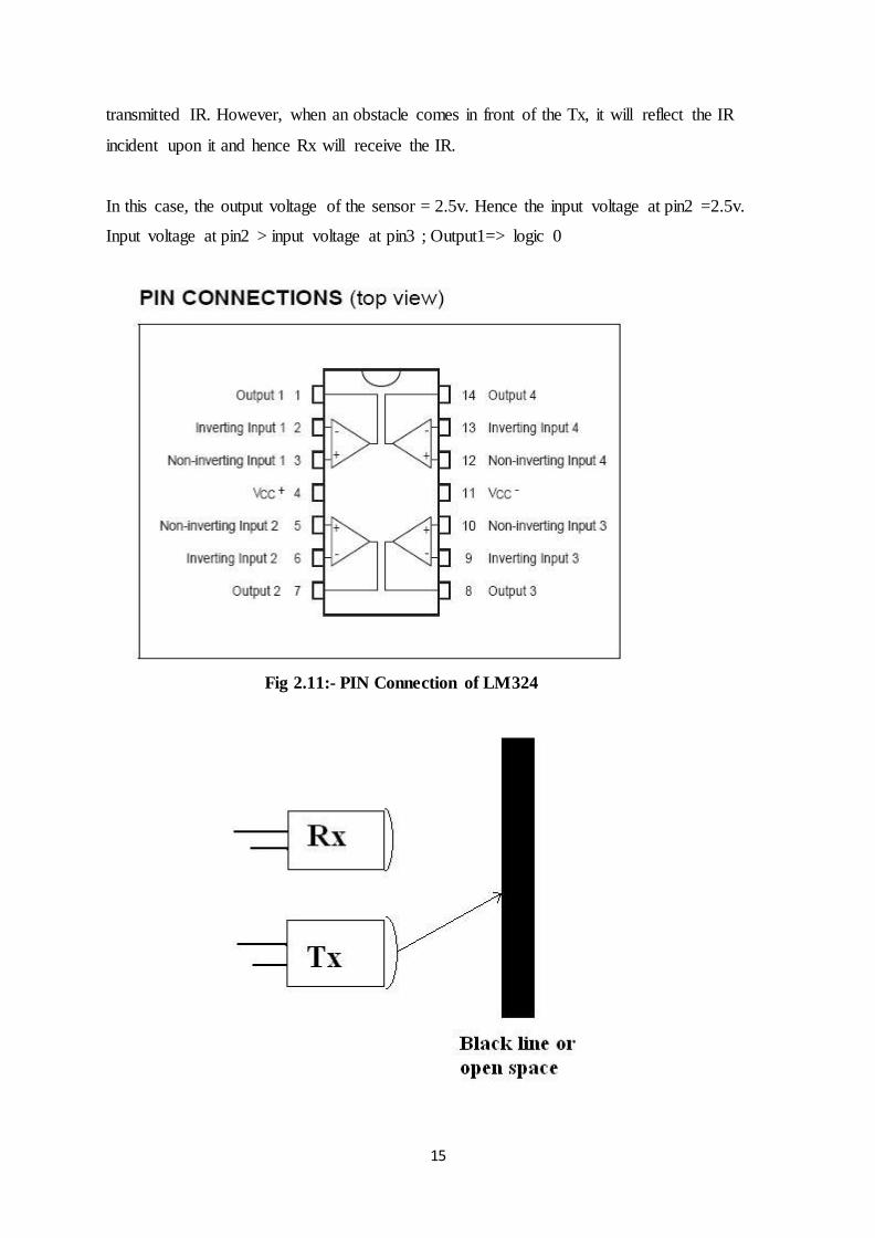
transmitted IR. However, when an obstacle comes in front of the Tx, it will reflect the IR
incident upon it and hence Rx will receive the IR.
In this case, the output voltage of the sensor = 2.5v. Hence the input voltage at pin2 =2.5v.
Input voltage at pin2 > input voltage at pin3 ; Output1=> logic 0
Fig 2.11:- PIN Connection of LM324

16
Case2: when IR is incident upon the Rx, the output voltage of the sensor = 1.8v. Hence the
input voltage at pin2 =1.8v.
Input voltage at pin2 logic 1
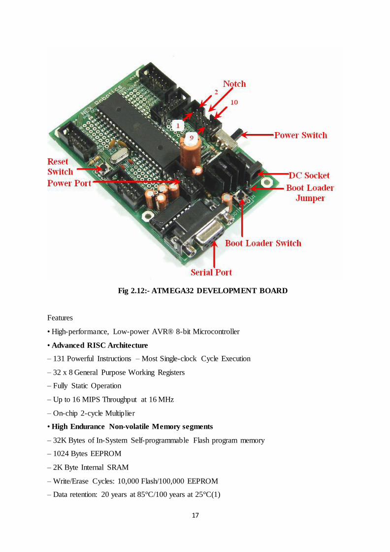
2.5 ATMEGA32 MICROCONTROLLER:-
ATMEGA 32 Development Board is made from double sided PTH PCB board to provide
extra strength to the connector joints for increased reliability. Board can work on 7 to 15V
AC or DC supply. It has built-in reverse polarity protection. 7805 voltage regulator has heat
sink for heat dissipation so that it can supply 1Amp current continuously without getting over
heated. It has switches for boot loading, reset and power. It also has RS232 interface with
DB9 female connector based on MAX232. All the ports are connected to standard 10 pin
FRC connectors. Open pads for connecting microcontroller’s pins to external devices are also
provided.
17
Fig 2.12:- ATMEGA32 DEVELOPMENT BOARD
Features
• High-performance, Low-power AVR® 8-bit Microcontroller
• Advanced RISC Architecture
– 131 Powerful Instructions – Most Single-clock Cycle Execution
– 32 x 8 General Purpose Working Registers
– Fully Static Operation
– Up to 16 MIPS Throughput at 16 MHz
– On-chip 2-cycle Multiplier
• High Endurance Non-volatile Memory segments
– 32K Bytes of In-System Self-programmable Flash program memory
– 1024 Bytes EEPROM
– 2K Byte Internal SRAM
– Write/Erase Cycles: 10,000 Flash/100,000 EEPROM
– Data retention: 20 years at 85°C/100 years at 25°C(1)

18
– Optional Boot Code Section with Independent Lock Bits In-System Programming by
On-chip Boot Program
--True Read-While-Write Operation
– Programming Lock for Software Security
• JTAG (IEEE std. 1149.1 Compliant) Interface
– Boundary-scan Capabilities According to the JTAG Standard
– Extensive On-chip Debug Support
– Programming of Flash, EEPROM, Fuses, and Lock Bits through the JTAG Interface
• Peripheral Features
– Two 8-bit Timer/Counters with Separate Prescalers and Compare Modes
– One 16-bit Timer/Counter with Separate Prescaler, Compare Mode, and Capture Mode
– Real Time Counter with Separate Oscillator
– Four PWM Channels
– 8-channel, 10-bit ADC 8 Single-ended Channels.7 Differential Channels in TQFP Package
Only2 Differential Channels with Programmable Gain at 1x, 10x, or 200x
– Byte-oriented Two-wire Serial Interface
– Programmable Serial USART
– Master/Slave SPI Serial Interface
– Programmable Watchdog Timer with Separate On-chip Oscillator
– On-chip Analog Comparator
• Special Microcontroller Features
– Power-on Reset and Programmable Brown-out Detection
– Internal Calibrated RC Oscillator
– External and Internal Interrupt Sources
– Six Sleep Modes: Idle, ADC Noise Reduction, Power-save, Power-down, Standby and
Extended Standby
• I/O and Packages
– 32 Programmable I/O Lines
– 40-pin PDIP, 44-lead TQFP, and 44-pad QFN/MLF
• Operating Voltages
– 2.7 - 5.5V for ATmega32L
– 4.5 - 5.5V for ATmega32
• Speed Grades
– 0 - 8 MHz for ATmega32L
19
– 0 - 16 MHz for ATmega32
• Power Consumption at 1 MHz, 3V, 25°C for ATmega32L
– Active: 1.1 mA
– Idle Mode: 0.35 mA
– Power-down Mode: < 1 μA
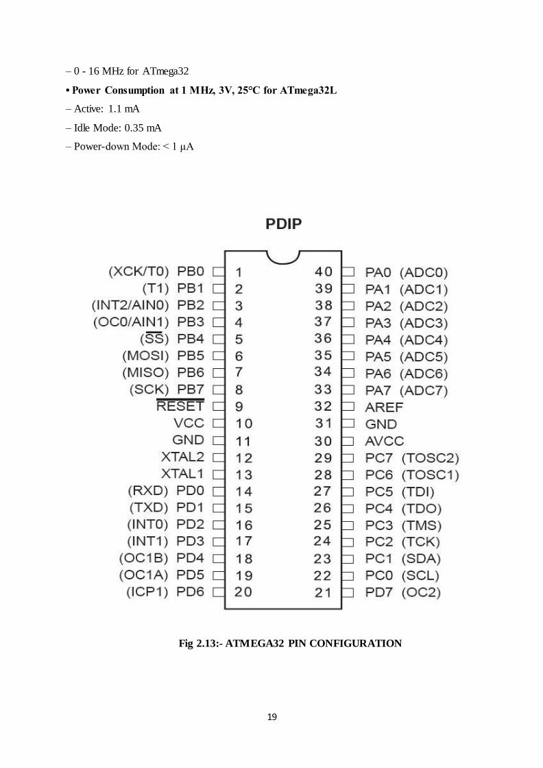
Fig 2.13:- ATMEGA32 PIN CONFIGURATION
20
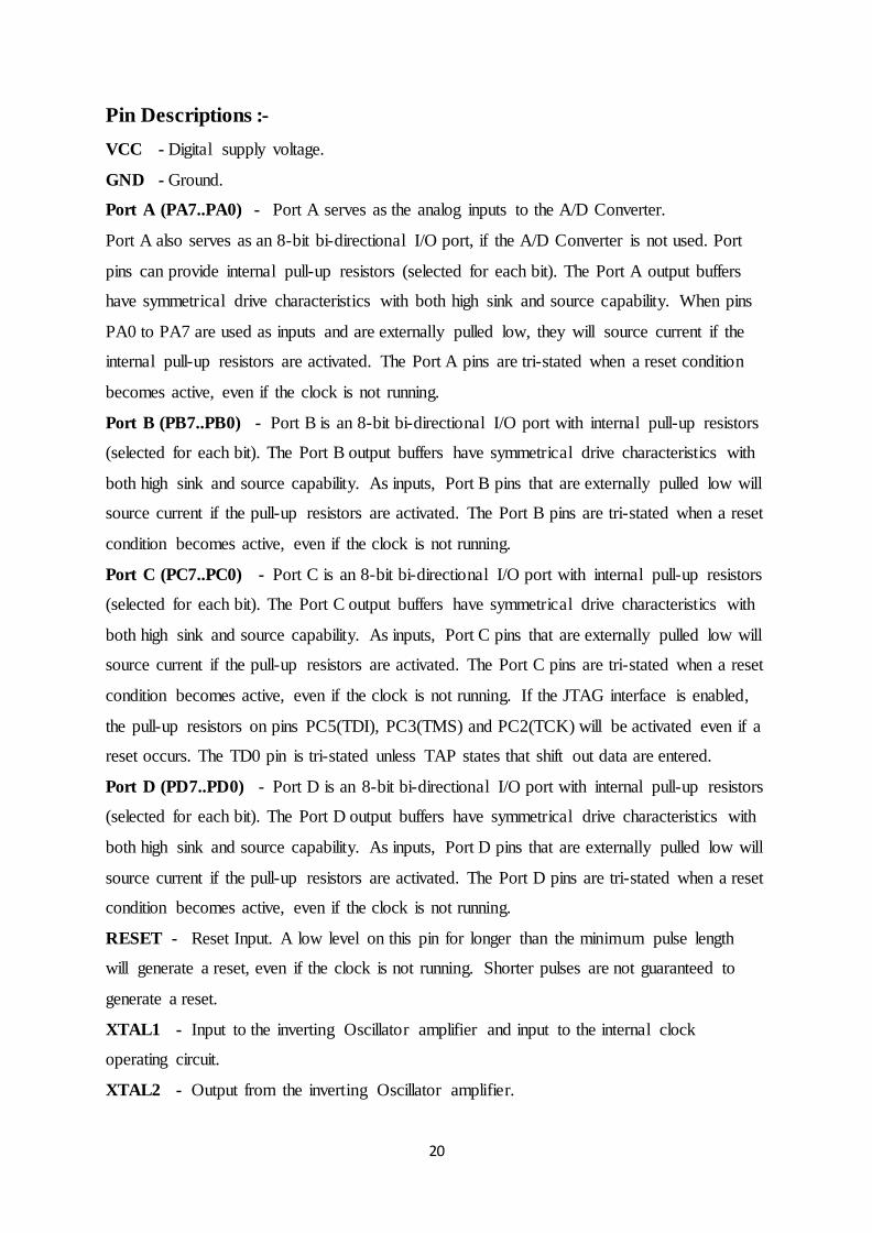
Pin Descriptions :-
VCC - Digital supply voltage.
GND - Ground.
Port A (PA7..PA0) - Port A serves as the analog inputs to the A/D Converter.
Port A also serves as an 8-bit bi-directional I/O port, if the A/D Converter is not used. Port
pins can provide internal pull-up resistors (selected for each bit). The Port A output buffers
have symmetrical drive characteristics with both high sink and source capability. When pins
PA0 to PA7 are used as inputs and are externally pulled low, they will source current if the
internal pull-up resistors are activated. The Port A pins are tri-stated when a reset condition
becomes active, even if the clock is not running.
Port B (PB7..PB0) - Port B is an 8-bit bi-directional I/O port with internal pull-up resistors
(selected for each bit). The Port B output buffers have symmetrical drive characteristics with
both high sink and source capability. As inputs, Port B pins that are externally pulled low will
source current if the pull-up resistors are activated. The Port B pins are tri-stated when a reset
condition becomes active, even if the clock is not running.
Port C (PC7..PC0) - Port C is an 8-bit bi-directional I/O port with internal pull-up resistors
(selected for each bit). The Port C output buffers have symmetrical drive characteristics with
both high sink and source capability. As inputs, Port C pins that are externally pulled low will
source current if the pull-up resistors are activated. The Port C pins are tri-stated when a reset
condition becomes active, even if the clock is not running. If the JTAG interface is enabled,
the pull-up resistors on pins PC5(TDI), PC3(TMS) and PC2(TCK) will be activated even if a
reset occurs. The TD0 pin is tri-stated unless TAP states that shift out data are entered.
Port D (PD7..PD0) - Port D is an 8-bit bi-directional I/O port with internal pull-up resistors
(selected for each bit). The Port D output buffers have symmetrical drive characteristics with
both high sink and source capability. As inputs, Port D pins that are externally pulled low will
source current if the pull-up resistors are activated. The Port D pins are tri-stated when a reset
condition becomes active, even if the clock is not running.
RESET - Reset Input. A low level on this pin for longer than the minimum pulse length
will generate a reset, even if the clock is not running. Shorter pulses are not guaranteed to
generate a reset.
XTAL1 - Input to the inverting Oscillator amplifier and input to the internal clock
operating circuit.
XTAL2 - Output from the inverting Oscillator amplifier.

21
AVCC - AVCC is the supply voltage pin for Port A and the A/D Converter. It should be
externally connected to VCC, even if the ADC is not used. If the ADC is used, it should be
connected to VCC through a low-pass filter.
AREF - AREF is the analog reference pin for the A/D Converter

22
Chapter – 03
SYSTEM HARDWARE &
AVR PROGRAM FOR
TRAFFIC CONTROL
SYSTEM
23
3.1 Introduction
The hardware part of this project is Programmable logic controller (PLC), Power Pack, a
traffic light model and pairs of Infra-Red Sensors.. The four ways traffic light model was
constructed to display how this traffic light control system is running. This traffic light model
has a complete set of traffic light signal which are red, yellow and green. Each lane also has
one limit switches represent as a sensor on the road. The sensors are placed on each lane to
detect the presence of a car at the junction.
3.2 Traffic light model
The four ways junction is developed using Woods, Screws, Light Emitting Diodes, Resistors
and 12V light bulbs. his traffic light model will be four lane based traffic system. In order to
display the simulation of the traffic light control system, each traffic light lane has a set of
traffic light signal “Red, Yellow, and Green” which changes from red to yellow and then
yellow to green and then yellow after that back to yellow and then finally red signal. In this
duration, all other lanes have red light glowing to allow the vehicles from the lane having
green signal to pass through that lane .As soon as the red light get switched on, the yellow
light of next lane in order switches on and then its traffic lights changes in the same sequence.
Each lane also has IR sensor on sideway of the road.
The sensor used for the design of these traffic light system is an infra-red detector which as
an infra-red diode and transistor as a pair. The sensors are placed on each lane to detect and
count the number of cars through that lane. Four infra-red sensors (detectors) are placed on 4
lanes coming to a junction, one per lane. The sensor is placed at a distance away from the
junction so that it doesn’t get disturbed by the vehicles stopping at the signal. These sensors
are connected to the PLC, which counts the pulses coming from the sensors.From this
combination of sensor, we will know the expected time for green signal on when each lane
change to the green signal

24
3.3 CODE FOR TRAFFIC CONTROL SYSTEM
#include<avr/io.h>
#include<util/delay.h>
int i,status1=0,status2=0,status3=0,status4=0;
int main()
{
DDRA=0x00;
DDRB=0xFF;
DDRD=0xFF;
PORTA=0xFF;
PORTB=0x00;
PORTD=0x00;
int en,first,street;
int emergency1,emergency2,emergency3,emergency4;
int count1,count2,count3,count4;
en=1;
first=1;
street=1;
count1=0;count2=0;count3=0;count4=0;
emergency1=0;emergency2=0;emergency3=0;emergency4=0;
while(en)
{
if((PINA & 0b00001000) == 0b00001000) //enable = 1 then system is on
{
if(first == 1)
{

25
PORTB|=0b10010000; // red lights on for 1 n 2
PORTD|=0b10010000; // red lights on for 3 n 4
_delay_ms(1000);
first=0;
}
else
;
}
else
break;
switch(street)
{
case 1: PORTB&=0b01111111; //set red light off
PORTB|=0b01000000; //set orange light on
_delay_ms(1000);
PORTB&=0b10111111; //set orange light off
PORTB|=0b00100000; //set green light on
for(int i=0;i<1;i++)
_delay_ms(1000); //green light on for atleast 10 seconds
status1=1;
while(status1)
{
if((PINA & 0b01000000) == 0b01000000) //check if second street sensor activates
{ _delay_ms(1000);
count1=count1+1;}
else
{
emergency1=1;
}

26
if(emergency1 || (count1 >= 4))
{
count1=0;
emergency1=0;
status1=0;
PORTB&=0b11011111; //green light goes off
PORTB|=0b01000000; //yellow light goes on
_delay_ms(1000);
PORTB&=0b10111111; //yellow light goes off
PORTB|=0b10000000; //red light goes on
}
}
break;
case 2: PORTB&=0b11101111; //set red light off
PORTB|=0b00001000; //set orange light on
_delay_ms(1000);
PORTB&=0b11110111; //set orange light off
PORTB|=0b00000100; //set green light on
for(i=0;i<1;i++)
_delay_ms(1000); //green light on for atleast 10 seconds
status2=1;
while(status2)
{
if((PINA & 0b00100000) == 0b00100000) //check if third street sensor activates
{_delay_ms(1000);
count2=count2+1; }

27
else
{emergency2=1;
}
if(emergency2 || (count2 >= 4))
{
count2=0;
emergency2=0;
status2=0;
PORTB&=0b11111011; //green light goes off
PORTB|=0b00001000; //yellow light goes on
_delay_ms(1000);
PORTB&=0b11110111; //yellow light goes off
PORTB|=0b00010000; //red light goes on
}
}
break;
case 3: PORTD&=0b01111111; //set red light off
PORTD|=0b01000000; //set orange light on
_delay_ms(1000);
PORTD&=0b10111111; //set orange light off
PORTD|=0b00100000; //set green light on
for(i=0;i<1;i++)
_delay_ms(1000); //green light on for atleast 10 seconds
status3=1;
while(status3)
{

28
if((PINA & 0b00010000) == 0b00010000) //check if fourth street sensor activates
{ _delay_ms(1000);
count3=count3+1;}
else
{
emergency3=3;
}
if(emergency3 || (count3 >= 4))
{
count3=0;
emergency3=0;
status3=0;
PORTD&=0b11011111; //green light goes off
PORTD|=0b01000000; //yellow light goes on
_delay_ms(1000);
PORTD&=0b10111111; //yellow light goes off
PORTD|=0b10000000; //red light goes on
}
}
break;
case 4: PORTD&=0b11101111; //set red light off
PORTD|=0b00001000; //set orange light on
_delay_ms(1000);
PORTD&=0b11110111; //set orange light off
PORTD|=0b00000100; //set green light on
for(i=0;i<1;i++)
_delay_ms(1000); //green light on for atleast 10 seconds
status4=1;
while(status4)

29
{
if((PINA & 0b10000000) == 0b10000000) //check if first street sensor activates
{ _delay_ms(1000);
count4=count4+1;}
else
{
emergency4=1;
}
if(emergency4 || (count4 >= 4))
{
count4=0;
emergency4=0;
status4=0;
PORTD&=0b11111011; //green light goes off
PORTD|=0b00001000; //yellow light goes on
_delay_ms(1000);
PORTD&=0b11110111; //yellow light goes off
PORTD|=0b00010000; //red light goes on
}
}
break;
default:
PORTB|=0b11111111;
PORTD|=0b11111111;
break;
}
street=street+1;
if(street==5)
street=1;
}
return 0;
30
Chapter – 04
RESULTS AND
DISCUSSIONS

31
All the system of the desired project was implemented and the results of the systems
illustrated in this Chapter.
4.1 The Prototype
The prototype was mainly built by combining the wood design and the electrical designs. The
12V power supply needed for the operation of microcontroller and relay board is supplied
using 12V DC power adapter.
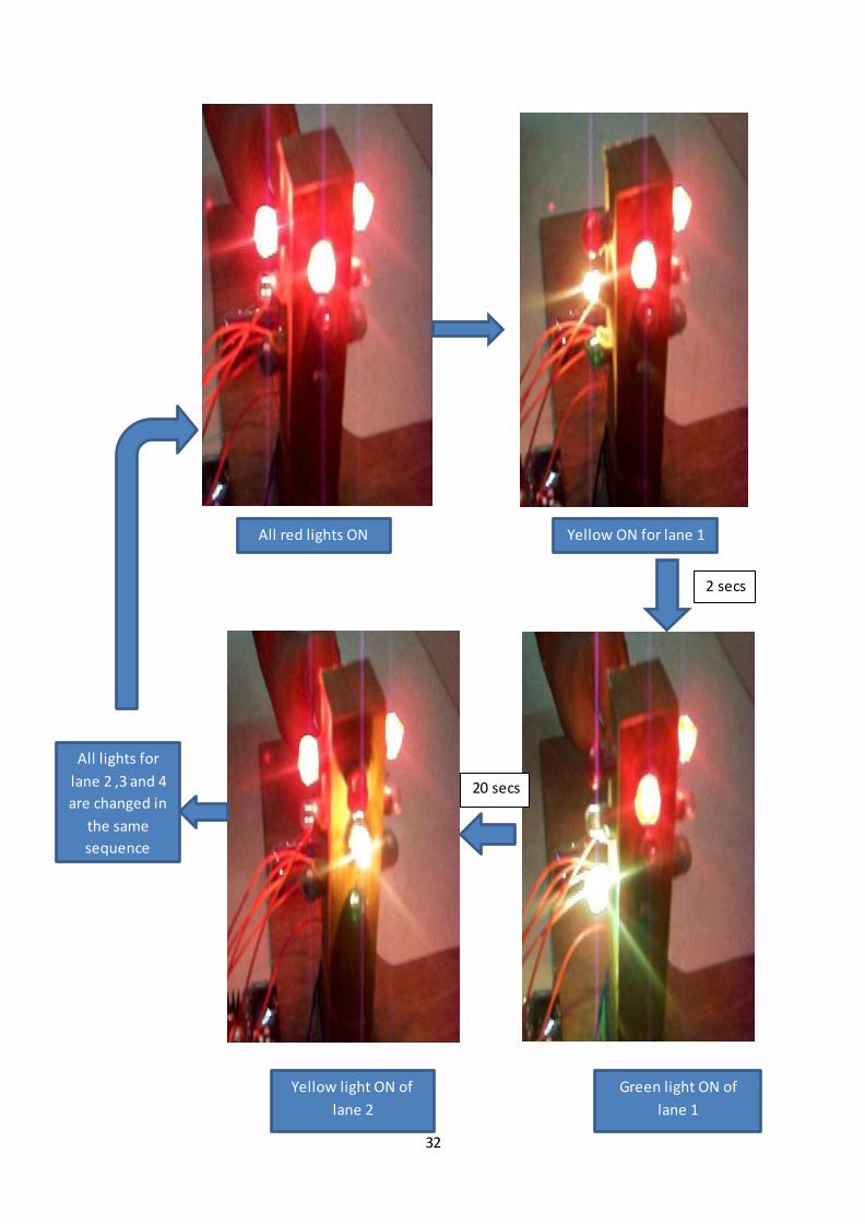
4.2 Project Operation
The program is downloaded into Atmega 32 microcontroller and 12V power is supplied to
both microcontroller and relay board. The traffic signal operation will start by the traffic
lights illuminating in first red for all the lanes. Then the yellow light of one lane is
illuminated for 2 seconds keeping the red light on for all the directions. Then green light of
that lane is illuminated for 15 seconds and then again yellow light is illuminated for 2
seconds. As soon as the yellow light goes off, the red light of next lane in clockwise sequence
changes to yellow and red light gets on of previous lane. The process is repeated for every
lane and for the same duration until the emergency status is activated.
NORMAL TRAFFIC ( emergency status off)
32
All red lights ON Yellow ON for lane 1
for 2
Green light ON of
lane 1
Yellow light ON of
lane 2
20 secs
2 secs
All lights for
lane 2 ,3 and 4
are changed in
the same
sequence
33
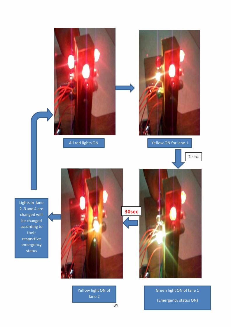
4.3 EMERGENCY STATUS ON
The IR sensor is attached at some distance from traffic signal along each lane.These sensor
keep track of amount of traffic along each road.When traffic signal is changing in normal
traffic in one lane,the IR sensor of next lane keeps checking on the amount of traffic in that
lane.When traffic becomes too high in that lane,the IR receiver detects the light reflected
back from the vehicle and the emergency status of that lane becomes ON and the time
duration of green signal of that lane is increased upto 30 secs to get rid off from the heavy
traffic.Same process is carried on for the all the lanes.
34
All red lights ON Yellow ON for lane 1
for 2
Green light ON of lane 1
(Emergency status ON)
Yellow light ON of
lane 2
30sec
2 secs
Lights in lane
2 ,3 and 4 are
changed will
be changed
according to
their
respective
emergency
status

35
4.4 Advantages
The traffic light system that had been developed presents several advantages. Since the
waiting time of the vehicles for the lights to change is optimal, the emission of carbon
monoxide from the vehicles is reduced. This will give a positive effect to the greenhouse
effect towards the environment.
The traffic light system will also save the motorists’ time and reduce their frustration while
waiting for the lights to change since it helps in reducing congestion at the traffic
intersections.

36
Chapter – 05
CONCLUSION

37
CONCLUSIONS AND RECOMMENDATIONS
5.1 Conclusion
A traffic light system had successfully been designed and developed with proper integration
of both the hardware and the software.. The infra-red sensors were interfaced with the
Atmega 32 Microcontroller. This interface is synchronized with the whole process of the
traffic system. It could be seen from the objectives of this project, that knowledge and skills
were combined together in order to complete this task. For this project, the knowledge of
sequential systems, electrical and electronics applications had been proven. The skill
involved in this project is the programming skills which makes you to think more as a
student. The system will encounter problems without proper integration of both the hardware
and software related to this project. Besides, this project, gave a challenge of having to learn
some other craft related work like painting, drilling, cutting of metals and woodwork.
Automatically, this project could be programmed in any way to control the traffic light model
and will be useful for planning road system.
5.2 Recommendation
The efficient operation can be achieved when there are enough Input/output cards for the
entire component used in this system. A more sophisticated and flexible PLC with enough
input/output cards should be used to provide enough functionality for the traffic light system.
The traffic light system should be programmed and necessary circuitry added to operate in
three modes namely: Day, Emergency and Night modes. A wider area board should be used
in order to achieve this.
This prototype can easily be implemented in real life situations. Increasing the number of
sensors to detect the presence of vehicles can further enhance the design of the traffic light
system. Another room for improvement is to have the infrared sensors replaced with an
imaging system/camera system so that it has a wide range of detection capabilities, which can
be enhanced and ventured into a perfect traffic system. Different sensors should be used on
each lane, to test communication strength with the microcontroller.
38
REFERENCES
REFERENCES
[1] Huang Q. and Miller R., 2003. The Design of Reliable Protocols for Wireless Traffic
Signal System, McGraw-Hill Publishes, Burr Ridge. pp 10-21. Accessed 05-05-2012
[2] Douglas Lewin& David Protheroe (1992), Design of Logic Systems, 2nd Edition,
Chapman and Hall, London. pp 128-132; 212-220. Accessed 05-05-2012.
[3] Pallas-Areny, R., Webster, J., 2001, “Sensors and Signal Conditioning”,John Wiley &
Sons. pp 50-56. Accessed 07-05-2012.
[4] A. Albagul et al, 2006.Design and Development of Sensor Based Traffic Light
System, American Journal of Applied Sciences 3 (3): 1745-1749, ISSN 1546-9239.
Accessed 07-05-2012.
[5] PC in control http://www.pc-control.co.uk/relays.htm Accessed 07-05-2012
[6] http://www.ezinearticles.com Computers and Technology › Hardware 13/05/07
[7] http://www.electronics- labs.com Electronics Labs Accessed 13/05/2012
[8] http://www.dnatechindia.com/Tutorial/8051-Tutorial/Interfacing-Relay-to-
Microcontroller.html DNA Technology India Accessed 13/05/2012
[9] http://www.robosense.in/index.php/tutorials/electronics/70-infra-red-ir-sensor-
designing-basic.html Robosense India Accessed 13/05/2012